1
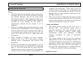
User Instructions
Cyrus III
Cyrus III Amplifier
1
English
INTRODUCTION
Cyrus III Amplifier
Congratulations
on
the
purchase
of
your
Cyrus III Amplifier. This piece of equipment is a precision
manufactured state-of-art product, constructed to the
highest standards and specifications. This manual contains
installation and operating instructions to enable the user to
connect up and operate the amplifier correctly, thus
ensuring the greatest satisfaction and long term use. This
instruction manual is divided into eight sections.
• Cautions
• Installation
• Operation
• Remote Control
• Additional Information
• Trouble Shooting
• Specifications
• Guarantee
To enable you to make full use of the comprehensive
facilities of the amplifier we suggest that you read these
sections which will explain the fundamental operations of
the unit.
English
2
CAUTION
POLARISED CONNECTOR (115V PRODUCTS ONLY)
To prevent electrical shock, match wide blade of plug to wide
slot and fully insert
Attention: Pour éviter les chocs électriques, introduire la lame la
plus large de la fiche dans la borne correspondante de la prise et
pousser jusqu'au fond.
Cyrus III Amplifier
CAUTIONS
Your Cyrus III Amplifier is factory set to operate from a
fixed mains supply voltage, which is marked on a label at
the rear of the unit. Before connecting, check that this
voltage is the same as your mains supply, i.e.
230V Products
115V Products
Voltage Range 220V-240V
Voltage Range 110V-120V
UNPACKING
RE-LOCATING
Always follow the instruction handbook and retain it in a
safe place for future reference.
Before proceeding with installing the Cyrus III Amplifier,
ensure that the following items are included in the
accessory box:
•
•
•
•
•
Instruction Manual
Power Cable
Remote Handset
4 Loudspeaker Plugs
Guarantee Card
The Cyrus III Amplifier is supplied ready for use in your
location. Care has been taken to ensure that the power
supply requirements are correctly set. Consult your
Mission distributor to arrange for conversion of your
Cyrus III should you move to another area with a different
mains voltage supply.
PRECAUTIONS REGARDING INSTALLATION
After removing these items, please retain the packing for
future use.
LOCATION
Install the amplifier in a well ventilated location where it
will not be exposed to high temperature or humidity.
3
Avoid installing the Cyrus III Amplifier in a location
which is exposed to direct rays of the sun, or near to hot
appliances or radiators. Placing and using the amplifier for
long periods on heat-generating sources will affect
performance and may damage the cabinet. Installation in a
damp or dusty environment may result in malfunction or
accident.
English
It is important not to allow any liquid or foreign object fall
into this unit. When routing the power cord avoid running
it over or near sharp objects.
If the amplifier is not to be used for a long period of time,
unplug the unit from the mains power supply.
This unit contains no user serviceable parts, therefore
never remove any panels from the unit or attempt to
service the unit. In the unlikely event of failure, please
refer to qualified service personnel.
INSTALLATION
1.
2.
3.
4.
5.
6.
7.
8.
Cyrus III Amplifier
Right Speaker Output
Left Speaker Output
Pre-Amplifier Output
Tape Recorder Output
Tape Input
Aux Input
CD Input
Phono Input
English
Fig.1 Amplifier (rear view)
4
9.
10.
11.
12.
13.
14.
15.
16.
Tuner Input
Video Input
MC-BUS System Connection
PSX-R Connection
Turntable Ground
Power Inlet
Mains Fuse
Power Switch
Cyrus III Amplifier
INSTALLATION
POSITIONING THE UNIT
IMPORTANT
The Cyrus III may be positioned as a free standing unit or
alongside another piece of audio equipment. Never stand
the Cyrus III under another unit. This may adversely affect
the efficient cooling of the Cyrus III. Never place the
Cyrus III on a carpet or similar material which may
hamper normal ventilation.
CONNECTING THE UNIT
NOTE TO USERS OF PSX-R WITH CYRUS III
In order to use a PSX-R regulated power supply with the
Cyrus III Amplifier, certain internal adjustments must be
made to the Cyrus III which can only be carried out by
an authorised Mission distributor or his agent.
Connection of the PSX-R to a Cyrus III which is not
correctly adjusted will result in fault condition display
on the Cyrus III. The Cyrus III fault indication system is
fully described in the Cyrus III handbook.
The Mains Supply
Connecting a PSX-R Power Supply (Optional)
The moulded IEC connector of the mains lead supplied
should be plugged in to the power inlet 14 on the rear of
the unit.
If a PSX-R is to be used with the Cyrus III, proceed to
connect the umbilical cord of the PSX-R to the 5-pin
Cannon input socket of the Cyrus III. When correctly
fitted, the connector will latch into place in the socket.
Note that when a PSX-R is in use, both the PSX-R power
supply and the Cyrus III will require mains power.
The mains fuse 15 is located on the rear panel next to the
power switch. It must only be replaced with the following
types:
U.K. / Europe - 230V
N. America / Far East - 115V
T1A/20mm
T2A/20mm
In the U.K., the Cyrus III comes with the mains plug
fitted. In the unlikely event that the plug fuse should need
replacing ensure that it is only replaced with a 3 Amp
Fuse.
5
English
Note:
For more details on the PSX-R, please refer to the Cyrus
PSX-R Instruction Manual.
INSTALLATION
Cyrus III Amplifier
Connecting a Turntable
Connect the phono cable from the turntable to the phono
input - PH 8 . Be sure to follow colour coding of the
plugs to keep left and right channels correctly ordered. If
the turntable has a ground wire fitted, connect this to the
Turntable ground connection 13 of the amplifier.
Note that the phono pre-amplifier of the Cyrus III is
suitable for use with a pick-up cartridge of either moving
magnet or high output moving coil design. A low output
moving coil cartridge will require a step-up transformer or
pre-amplifier to be used externally. Your dealer can advise
if this is necessary.
Connecting other Inputs
Connect a phono cable between each system component
and the rear panel sockets as marked on the rear panel
diagram. At all times observe the colour coding of the
phono cable for left and right channel identification. The
Cyrus III provides for connection of a CD Player -CD 7 ,
a tuner - TU 9 , a video recorder or video disc player - VI
10 and an auxiliary input - AU 6 .
,
The AU input can be used for connection of a wide variety
of products such as a second CD player, tuner or VCR, an
electronic keyboard, an organ or a second tape deck if
only replay is necessary. Always check the technical
English
6
specification of these products before connecting to your
Cyrus III. Consult your dealer if in doubt.
Connecting a Tape Recorder
Two phono cables are necessary for connection of a tape
recorder when used. Firstly, connect a phono cable from
the Output or Playback sockets of the tape recorder to the
Tape Input - TP IN 5 of the Cyrus III. Then connect a
second phono cable from the Input or Record sockets of
the tape recorder to the Tape Record Output - TP OUT 4
sockets of the Cyrus III.
Connecting Loudspeakers
The left and right loudspeakers are connected to the rear
panel sockets 1 and 2 of the Cyrus III respectively
using the plugs provided. First, fit the plugs to the
loudspeaker cables. Carefully note that the cable carries
marking or colours for polarity, (+ and -) may also be
marked for direction with an arrow. For correct operation,
it is essential that the (+ and - ) terminals of the amplifier
are
connected
to
the
corresponding
(+ and -) terminals of the loudspeakers. When fitting the
plugs to the cables be sure to line up (+ and -) at each end.
The loudspeaker plugs can now be fitted to the amplifier
sockets.
Cyrus III Amplifier
1.
2.
3.
4.
5.
6.
OPERATION
Standby Switch
Standby Light
Balance
Remote Eye
Volume Level
Tape
7.
8.
9.
10.
11.
12.
Fig. 2 Amplifier (front view)
7
English
Auxiliary
Video
Tuner
CD
Phono
Mute
OPERATION
Cyrus III Amplifier
RECORDING AND PLAYBACK
POWER
The mains power switch 16 is located on the rear panel of
the amplifier (refer to the rear panel drawing on page 4).
This switch should be left on for normal operation, except
when left unattended for a long period. In this case the
mains power should then be switched off or the product
disconnected from the AC supply.
Refer now to figure 2, front panel drawing on page 7.
When the amplifier is in regular use and power is
permanently applied, the STANDBY key 1 can be used
for power control. The Standby light 2 will show red
when the amplifier is off and green when operating. The
Cyrus III will also switch on when an input source 7 - 11
is selected.
If the tape recorder connections are made according to the
previous instruction in this manual, then you should be
able to listen to a recording by selecting the Tape Monitor
key - TP 6 . The indicator above the TP key will now
light in addition to the selected source. To cancel this,
press the TP key again. Should your tape deck have a
three-head facility, then you can use the TP key to monitor
the recording quality directly from the third head, whilst
recording.
You can record from a source by pressing the relevant
Key 7 - 11 and following the recording instructions in
your tape deck manual.
VOLUME AND BALANCE CONTROL
SELECTING AN INPUT FOR LISTENING
The five input keys switch between selected input sources.
These can be a turntable - PH, a CD player - CD, a tuner TU, a video recorder or video disc player - VI and a spare
auxiliary input - AU. When an input key is selected, the
red indicator above the key will turn on.
English
8
The rotary knob of the Cyrus III has a dual function of
volume and balance control. The control is applied in
precision steps of 1dB with 0.2dB channel balance
accuracy throughout the volume range. The light ring
around the knob performs different functions in each
mode of operation.
Cyrus III Amplifier
Remote Control Handset
as supplied with Cyrus III only
OPERATION
Volume Control
In normal mode the
rotary knob of the Cyrus
III controls the volume in 1dB steps from its maximum
level down to the minimum. The light ring around the
knob is calibrated to give the correct loudness scale to the
changes in the volume level. When the volume is set to the
minimum level the first L.E.D. indicator on the light ring
will be RED. The currently set volume is preserved when
the unit is put into standby mode. Should the level be set
abnormally high when standby is selected, this will be
automatically adjusted down to a safer level on switch-on.
Balance Control
Your Cyrus III is equipped with a Balance control key 3
which is used to change the operation mode of the rotary
knob to that of Left - Right Balance. When selected, the
light ring will change function to work in "reverse video" format with the unlit section indicating the position
of L-R balance.
Normal Listening Level
- Mute
9
Channel Balance
Normal
English
When in this mode, you can control the L-R balance by up
to +/-4dB as well as switching one channel off completely
when the control is turned to an extreme. The balance
mode is automatically reset after 5 seconds of inactivity of
the rotary knob. It can also be reset by pressing the
balance key again.
Mute
Pressing the Mute Key 12 will fade out the volume to
minimum level without disturbing the existing setting.
When muted the minimum level indicator light, RED will
light as well as the existing GREEN light to show that the
output is muted. Changing the volume knob or pressing
the Mute key will reset the mute, fading in the original
volume setting.
Channel Balance
R - CH + 2dB
Channel Balance
L - Ch Only
REMOTE CONTROL
Cyrus III Amplifier
Controls for Cyrus III Amplifier
Controls for Cyrus FM7 Tuner
Power Off Control for
Cyrus III and Cyrus FM7
1.
2.
3.
4.
5.
6.
7.
8.
English
Power Off
Numeric Keypad
Mono
Mute
Tape Monitor
Balance
CD Select
Tuner Select
9.
10.
11.
12.
13.
14.
15.
10
Video Select
Aux Select
Volume Control
Seek Down
Seek Up
Store
Display
Cyrus III Amplifier
REMOTE CONTROL
Auto Tuning
REMOTE OPERATION
Power
Your Cyrus III may be turned on by selecting any Input
Select Key 7 - 10 on the Cyrus amp - tuner handset. If
an FM7 is used, then pressing the Tuner Select Key - TUN
8 will also switch the tuner on. To switch the power off
from the remote position, press the "Cyrus System Off"
RED Key on the handset.
Cyrus III Controls
The remote control handset of the Cyrus III serves a dual
purpose of controlling your amplifier as well as the Cyrus
FM7 Tuner should you own one. The top three rows of
keys on the handset replicate the front panel of the
Cyrus III making it possible to have full control of the
amplifier from a remote position.
FM7 Controls
Your FM7's functionality is greatly enhanced when using
it with your Cyrus amp - tuner handset. The following
paragraphs describe the FM7 remote control functions in
detail. Read the subsequent paragraphs if you own a Cyrus
FM7.
11
English
In addition to the normal SEEK UP tuning facility
available on the FM7 front panel, the remote control
handset provides the possibility of scanning down the
broadcast band providing additional flexibility.
Preset Storage
Building onto the seven presets available on the front
panel, the remote control handset gives access to 29 preset
locations in total. To store a preset, select a station using
AUTO or MANUAL tuning and press the STORE key 14 .
The preset digits on the display will flash prompting you
to enter a two-digit preset location number. For location
numbers under 9 the digit must be preceded by a zero.
Preset Selection
The numeric keypad of the handset enables direct entry of
the preset location number. To select a preset enter a twodigit number up to 29. Exceptions to this are location
numbers 3 to 9 which can be accessed by a single digit
entry.
REMOTE CONTROL
Cyrus III Amplifier
Mono Operation
The tuner may be forced into mono operation using the
MONO key 3 on the handset. This is useful in cutting
the background noise substantially when tuned to weak
transmissions. This function may also be beneficial in
improving quality of centre-image broadcasts such as
news, sports, etc.
Should you wish to permanently receive a particular in
MONO proceed as follows. Tune to the desired station
and press the MONO key 3 . The mono symbol ' ' will
be displayed on the front panel in place of the stereo
symbol ' '. Press the STORE key 14 and dial in the
preset location number as required.
Display Control
The DISPLAY key 15 on the handset can be used to
switch the display of the FM7 off should this be preferred.
Pressing this key again restores the display to its normal
mode. Switching the display off reduces the power
consumption of the unit and eliminates the digital traffic
related to the display update function. This can improve
the overall quality of reception without adversely affecting
the normal functions of your FM7.
English
12
Cyrus III Amplifier
ADDITIONAL INFORMATION
KNOW YOUR CYRUS III
Power
•
When first powered up from the mains switch on the
rear panel, the Cyrus III will run a self-test, checking
the internal functions and all the front panel
indicators in sequence. After completion of this cycle
the amplifier will revert to Standby mode. When first
switched on from standby the CD input is
automatically selected and the volume is set to
minimum.
•
When set to Standby the front panel settings for input
selection and Volume/Balance will be retained until
next used. If the unit is put in standby mode while set
to abnormally high volume levels, the Cyrus III will
power on at the safe level of -15dB when next
switched on.
•
When switched to Standby, the power amplifier
section of the Cyrus III is shut down to ensure
minimal power consumption and reduced heat
generation.
•
If other Cyrus products are used with the Cyrus III,
they can be connected via the MC-BUS as shown on
page 15. This will ensure that the power ON/OFF
will function in unison between all Cyrus products,
locally as well as via the remote control handset. For
13
English
•
example, if the tuner input - TUN of the Cyrus III is
selected, them the FM7 tuner will automatically turn
on. Conversely if the Standby key on the Cyrus III is
pressed, then all Cyrus products connected via the
MC-BUS will turn off.
The Cyrus III runs at a high quiescent current setting
to ensure deep operation into class AB. This naturally
results in the enclosure to be warm to the touch and
therefore should not be a cause for concern.
Volume and Balance
•
The volume control system of your Cyrus III is a
precision 1dB - step attenuator design which is
musically transparent. One major advantage of this
design is its absolute accuracy, which unlike
conventional volume pots maintains +/-0.1dB
tolerance throughout 63 steps of attenuation
available.
•
The volume setting of your Cyrus III is achieved
independently for the Left and Right channels. The
L-R channel balance can therefore be controlled by
applying an offset to the attenuation of one channel
with respect to the other with the same degree of
precision. The channel balance is maintained within
+/- 0.2dB across the full volume control range.
Signal Processors
ADDITIONAL INFORMATION
•
A multitude of signal/sound processing components
such as Dolby Pro-Logic sound processors may be
used with the Cyrus III by connection inside the
"Tape Loop" of the amplifier. In this case the tape
recorder is normally connected to the processor
instead. For detailed connectivity refer to the relevant
component's manual.
Cyrus III Amplifier
•
Bi-amping / Tri-amping
•
The buffered pre-amplifier output of the Cyrus III
may be used in conjunction with added power
amplifier blocks to upgrade your loudspeaker system
through Bi-amping or Tri-amping. In this case you
should check that the sensitivity of the power
amplifier modules are compatible with the output
level of the Cyrus III.
External Regulated Power Supply - PSX-R
•
Addition of a PSX-R which is a highly regulated DC
power supply will upgrade the sonic performance of
your Cyrus III as well as enhancing its current drive
ability into difficult loudspeaker loads. Should you
decide to add this optional extra to your system, be
sure to have your Cyrus III converted by your dealer
or an authorised Cyrus Service Organisation.
When Cyrus III / PSX-R combination is installed all
analogue and signal related sections of the Cyrus III
are powered from this clean and highly stable power
source, while the remaining power requirements are
supplied internally. This technique ensures complete
isolation of the sensitive analogue sections from the
control side as well as the AC mains-borne noise and
power supply ripple which of course, enhances the
delicacy and transparency of the reproduced music
programme.
MC-BUS System Connection
•
This is an optional connection via the MC-Bus
sockets 11 (see rear panel drawing on page 4), which
can provide unified power control of a complete
Cyrus system from your Cyrus III. The MC-Bus
connections should be wired as a 'loop' using single
RCA phono interconnects. The diagram on the next
page shows a typical Cyrus system of Cyrus DAD7,
Cyrus FM7, Cyrus III and Cyrus Power with such an
MC-Bus loop connected. Referring to this diagram,
connect the first cable between the MC-Bus output of
the Cyrus III and the MC-Bus input of the next Cyrus
component. Continue to wire each product MC-Bus
output to the next input, finally returning to the
Cyrus III input to complete the loop.
Operating a system with MC-Bus connected
English
14
Cyrus III Amplifier
ADDITIONAL INFORMATION
which ensures consistency and quality levels hitherto
impossible to achieve in an audio product of this
price range.
AMPLIFIER MAINTENANCE
•
•
15
There are no user serviceable parts in the Cyrus III so
there is no reason to remove any of the panels. After
disconnecting the mains power supply, the cabinet may be
cleaned using a chamois leather, slightly moistened with
water. DO NOT use cleaning agents containing alcohol,
spirits, ammonia or abrasives.
When the above connections have been made it will
now be possible to control the power function of the
entire system from the Cyrus III, either from the front
panel or by remote control. Selecting 'CD' from the
Cyrus III front panel will then switch on the Cyrus
III, the Cyrus Power and the Cyrus DAD7 CD player.
When the Cyrus III is set to Standby, all system
components will also switch off.
Another important function of the MC-Bus system is
to enable Micro-processor controlled testing and
calibration to be applied during the production phase
of the Cyrus range of products. Using the MC-Bus all
possible tests relating to the correct operation of the
system are performed in a relatively short period of
time. Such rigorous tests are only possible with the
aid of this proprietary communication bus system
English
THE MISSION/CYRUS GROUP MANUFACTURE
•
•
•
•
•
•
•
•
•
•
Loudspeakers
Loudspeaker Stands
Loudspeaker Cables
Compact Disc Players
D-to-A Converters
Amplifiers
Tuners
Home Theatre Processors
Regulated Audio Power Supplies
Isoplat (Vibration Isolation Platform)
TROUBLESHOOTING
Cyrus III Amplifier
No Sound from one Speaker
TROUBLESHOOTING GUIDE
If you suspect that your Cyrus III is not operating to
specification please read through this section before
returning the amplifier to your local dealer.
No Sound from either Speaker
•
Check the Balance Control is not set to left or right
limits.
•
If your loudspeakers are fitted with protection fuses,
check that the fuse is intact.
•
Check the interconnect cable integrity on the rear
panel and at source. If possible use another
interconnect cable.
Check the speaker cable connection integrity of the
missing channel.
•
Check that the amplifier is on. Green power light
should be "ON".
•
Check that the amplifier responds to different front
panel commands.
•
•
Check that the MUTE light on the volume control
light ring is "OFF".
If the problem persists proceed as follows:
•
Check that the relevant programme source is selected
and is working. For example the CD Player is
playing.
•
Check that the Tape Monitor is not selected
inadvertently, RED light above the TP key is "OFF".
•
Check that the loudspeakers are not inadvertently
disconnected.
•
Check that the installation is correct according to the
installation guide in this booklet.
•
Check that there is not fault indication on your Cyrus
III front panel. If so refer to the next section.
English
16
•
Change the programme source using the suspected
interconnect cable and check that the problem still
exists. If the fault is removed by doing this then the
original source is at fault.
•
Interchange the left and right connection of the
interconnect cable at SOURCE. If the missing
channel switches over then there is a problem in one
channel of the source or the interconnect. If the
sound disappears totally then there may be two
problems present in your system.
•
Change over the left and right channels of your
loudspeaker on the Cyrus III rear panel. If the
problem stays in the same channel, then there is a
Cyrus III Amplifier
fault in the
Now switch
the problem
otherwise it
defective.
TROUBLESHOOTING
loudspeaker cable or the loudspeaker.
the cable at the loudspeaker end and if
switches then the loudspeaker is faulty,
is the loudspeaker cable which may be
Note:
Be sure to restore the system to its original configuration
after completion of the above series of tests.
Spurious Sounds from the Loudspeakers
If you experience strange or unnatural noises from your
system proceed as follows:
•
Select another source to ensure that this is not a
common problem. If the problem remains switch the
Cyrus III off at the rear panel and turn it on again
after a few seconds.
•
If the problem is limited to a single source, check the
integrity of the interconnection to the source and in
the case of a phono turntable, check that the phono
ground wire is secured at the rear panel of the Cyrus
III.
17
English
TROUBLESHOOTING
Cyrus III Amplifier
FAULT INDICATION SYSTEM
FAULT INDICATION WHEN IN USE
The Cyrus III has a unique fault indication system, built in
to help you to diagnose the possible cause of a problem.
All fault indications are presented by the Standby light on
the front panel of your Cyrus III.
Flashing GREEN / YELLOW
•
FAULT INDICATION AT FIRST INSTALLATION
Flashing RED
•
This indicates that the Cyrus III has been adjusted for
use with a PSX-R power supply, but a PSX-R has not
been connected correctly. In this case, check that the
PSX-R umbilical cord is connected to the rear panel
PSX-R socket and that the mains power is connected
securely to both products. If the connections are in
order and the indication persists, return the unit(s) to
your Mission distributor.
Flashing RED
•
Flashing GREEN
•
This indicates that a PSX-R power supply has been
connected to a Cyrus III without the correct
preparation for PSX-R use. In this case, remove the
PSX-R
cable
and
re-test
the
Cyrus III. If the Cyrus III functions correctly, return
the amplifier to a Mission distributor for
PSX-R adjustment.
English
18
This indicates an overload condition in at least one
channel. If the problem is of a temporary nature (for
example excessive volume setting), normal operation
will resume after four seconds. If the fault indication
persists, there may be a problem with the
loudspeakers or their connections. In this case,
switch off the power at the rear of the Cyrus III and
disconnect the speaker cables from the rear panel. If
the fault indication has now cleared, check the
loudspeakers, cables and plugs carefully for loose
strands of wire which may cause a short circuit.
This indicates an internal problem with the Cyrus III
or PSX-R (where used). If the problem does not clear
when the amplifier power is reset, return the unit(s)
to your Mission distributor for checking.
Flashing GREEN
•
This indicates a fault reported from the PSX-R. In this
case, switch off the power to both the Cyrus III and
the PSX-R and switch on again. If the problem does
not clear, return both units to your Mission
distributor for checking.
Cyrus III Amplifier
SPECIFICATIONS
AUDIO PERFORMANCE
Input Sensitivity ..................... Line.........................200mV
(50W/8Ω) ............................... Phono.....................2.75mV
Input Impedance..................... Line............................22kΩ
Phono.........................47kΩ
+50pF
THD+N (AMP)
(both channels driven) ........... 8 Ohms .....................0.02%
(1kHz half power).................. 4 Ohm.......................0.03%
POWER SUPPLY
Voltage
See the plate attached to the rear of unit
Volume Control Accuracy ................................... +/-0.1dB
0dB to - 63dB
Power Consumption
Channel Balance .................................................. +/-0.2dB
0dB to -63dB
Standby .....................................................................(12W)
ON (No Load)...........................................................(23W)
ON (2 x 50W/Ch) ...................................................(185W)
Frequency Response (-3dB)... Line................. 2Hz, 80kHz
RIAA accuracy....................... Phono................... +/-0.2dB
Safety Requirements................................................IEC 65
Signal to Noise Ratio ............. Line......................... 98dBA
(A-WTD) ................................ Phono...................... 80dBA
Power Output ......................... 8 Ohms ....................... 50W
(both channels driven) ........... 4 Ohms .......................70W
ENCLOSURE
Dimensions (WxHxD).........................215 x 75 x 365 mm
Weight....................................................................... 4.6Kg
THD+N (PRE - AMP) ........... Line........................ 0.004%
1kHz ....................................... Phono....................... 0.03%
Material................................................... Magnesium alloy
and Aluminium alloy
The company reserves the right to change this specification without prior notice.
Part No. AM-MANUL/Iss.02-9511 File:7AEN5B11.WIM
19
English
GUARANTEE
Cyrus III Amplifier
This guarantee only becomes effective if the guarantee
card enclosed is completed by the Dealer and the
purchaser and returned to MISSION or Distributor within
8 days of purchase.
This guarantee excludes:
i)
ii)
All damage caused through accident, misuse, wear
and tear, neglect or through incorrect installation,
adjustment or repair by unauthorised personnel.
Liability for damage or loss occurring in transit to or
from the purchaser.
Claims under this guarantee must, whenever possible, be
made through the Dealer from whom the equipment was
purchased or if that is not convenient, through another
authorised MISSION/CYRUS dealer.
MISSION shall not be liable for any consequential
damage, loss or injury whatsoever, arising from or in
conjunction with this equipment.
English
20
The cost of carriage (to or from the Dealer) shall be borne
by the purchaser.
This guarantee is personal to the original Purchaser and is
not transferable.
If equipment is found on examination to comply with the
published specification, MISSION reserves the right to
make a charge for examination and for return carriage.
No Dealer or Distributor has any authority to vary the
terms of this guarantee.
Any unauthorised servicing will result in loss of
guarantee.
We strongly recommend that you retain the sales receipt
for your CYRUS equipment in case of any warranty claim.
The above conditions do not affect your statutory rights as
a consumer.
NOTES
English
Cyrus III Amplifier
21