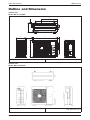
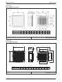
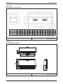
1
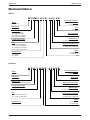
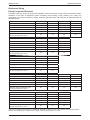
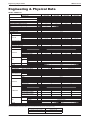
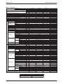
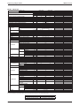
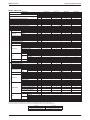
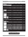
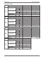
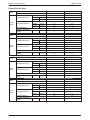
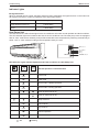
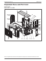
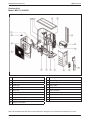
Catalog TM - M5LCY - I - 2011 Supercedes: M5LCY-I-2010 Inverter-Y Single Split Series I Models: M5LCY 10DR M5LCY 15DR M5LCY 20CR M5LCY 25CR Table of Contents TM-M5LCY-I-2011 Table of Contents Nomenclature......................................................................................................................1 Indoor ............................................................................................................................1 Outdoor..........................................................................................................................1 Product Line-Up.............................................................................................................3 Application Information .....................................................................................................6 Operating Range ...........................................................................................................6 Refrigerant Circuit Diagram ...........................................................................................6 Installation Guideline .....................................................................................................7 Engineering & Physical Data .............................................................................................9 Safety Devices Data ....................................................................................................14 Outline and Dimension ....................................................................................................17 Wiring Diagram .................................................................................................................21 Service and Maintenance.................................................................................................30 Troubleshooting ...............................................................................................................32 Exploded View and Part List ...........................................................................................41 “McQuay” is a registered trademark of McQuay International. All rights reserved. © 2011 McQuay International. All rights reserved throughout the world. Bulletin illustrations cover the general appearance of McQuay International products at the time of publication. We reserve the right to change design and construction specifications at any time without notice. Nomenclature TM-M5LCY-I-2011 Nomenclature Indoor M 5 WM Y 10 J R – A C L A D Product Specification Variation D: Fourth Issue Brand M: McQuay Refrigerant 5: R410A Grille A: Grille A Product Type WM: Wall Mounted CK: Ceiling Cassette CC: Ceiling Concealed CM: Ceiling Convertible Type of Air Filter L: Saranet Market Region C: Export with CE Marking Inverter System Type Y: Y Series Size 10 : 8,872~10,236 Btu/h 15 : 11,942~12,966 Btu/h 20 : 18,600~19,176 Btu/h 25 : 21,200~21,837 Btu/h Electrical Characteristics A : 50Hz / 1Ph / 220-240V F : 50Hz / 3Ph / 380-415V Model “ ”: Cooling Only R: Heat Pump Product series J: J Series C: C Series E: E Series Outdoor M 5 LC Y 10 D R – A C O U B Brand M: McQuay Product Specification Variation B: Second Issue Refrigerant 5: R410A Compressor U: Panasonic Product Type LC: Single Split Condensing Unit Inverter System Type Y: Y Series Size 10 : 8,872~10,236 Btu/h 15 : 11,942~12,966 Btu/h Product series D: D Series 1 Specifications Variation O: Standard Unit Market Region C: Export with CE Marking Electrical Characteristics A : 50Hz / 1Ph / 220-240V F : 50Hz / 3Ph / 380-415V Model “ ”: Cooling Only R: Heat Pump TM-M5LCY-I-2011 Nomenclature M 5 LC Y 20 C R – A C D O A Brand M: McQuay Product Specification Variation A: First Issue Refrigerant 5: R410A Compressor D: Daikin Product Type LC: Single Split Condensing Unit Inverter System Type Y: Y Series Size 20 : 18,600~19,176 Btu/h 25 : 21,200~21,837 Btu/h Product series C: C Series Specifications Variation O: Standard Unit Market Region C: Export with CE Marking Electrical Characteristics A : 50Hz / 1Ph / 220-240V F : 50Hz / 3Ph / 380-415V Model “ ”: Cooling Only R: Heat Pump 2 3 10CR ACOB X X X 15CR ACOB X X X 20CR ACOB X X X PLCKY-CR NGS01 X X Nano Technology Air Filtration Negative Ionizer Saranet Filter M5CKY X Others Marking Air Purification PCB Handset Nomenclature W_2_03A Saranet Filter CE Auto Restart 10JR ACLAD X X X X X 15JR ACLAD X X X X X 20JR ACLTC X X X X X 25JR ACLTC X X X X X Others Marking Air Purification PCB Handset Nomenclature Nano Technology Air Filtration Negative Ionizer APGS01 HEATPUMP M5WMY C_2_01A_M Auto Restart APGS01 CE HEATPUMP Nomenclature TM-M5LCY-I-2011 Product Line-Up Indoor Unit M5WMY-J Series Classification Indoor Unit M5CKY-C Series Classification C_2_01A_M Saranet Filter CE Auto Restart M5CCY 10CR ACPA X X X X X 15CR ACPA X X X X X 20CR ACPA X X X X X 25CR ACPA X X X X X Nano Technology Air Filtration Auto Restart X X X 25ER ACOB X X X PLCKY-ER NGS01 X Others Marking ACOB Others Marking Air Purification PCB Handset Nomenclature Nano Technology Air Filtration Negative Ionizer Saranet Filter C_2_01A_M CE APGS01 20ER X Air Purification PCB Handset Nomenclature HEATPUMP M5CKY Negative Ionizer Netware 3C HEATPUMP TM-M5LCY-I-2011 Nomenclature Indoor Unit M5CKY-E Series Classification X Indoor Unit M5CCY-C Series Classification 4 HEATPUMP 5 OYL CONTROLLER CE DC Inverter Swing Compressor DC Inverter Single Rotary LP HP Contactor Bare Fin Blue Coated Gold Coated EXV C_2_01A_M Saranet Filter CE Auto Restart ACAA X X X X X 20ER ACAA X X X X X 25ER ACAA X X X X X 10DR ACOUB X X X X X 15DR ACOUB X X X X X 20CR ACDOA X X X X X 25CR ACDOA X X X X X Others Marking Air Purification PCB Handset Nomenclature Nano Technology Air Filtration Negative Ionizer APGS01 15ER Others Marking Compressor Safety Devices FIN Refrigerant Control PCB M5CMY Cap Tube M5LCY Nomenclature HEATPUMP Nomenclature TM-M5LCY-I-2011 Indoor Unit M5CMY-E Series Classification Outdoor Unit M5LCY Classification TM-M5LCY-I-2011 Application Information Application Information Operating Range Ensure the operating temperature is in allowable range. Heatpump Heating Cooling Standard point Outdoor temp. (°CDB) Outdoor temp. (°CWB) 18 10 STD 6 -15 46 43 STD 35 -10 15 20 21 27 Indoor temp. (°CDB) 14 19 23 Indoor temp. (°CWB) Caution : The use of your air conditioner outside the range of working temperature and humidity can result in serious failure. Refrigerant Circuit Diagram Model: M5LCY 10DR - M5WMY 10JR / M5CKY 10CR / M5CCY 10CR M5LCY 15DR - M5WMY 15JR / M5CKY 15CR / M5CCY 15CR / M5CMY 15ER M5LCY 20CR - M5WMY 20JR / M5CKY 20C/ER / M5CCY 20CR / M5CMY 20ER M5LCY 25CR - M5WMY 25JR / M5CKY 25ER / M5CCY 25CR / M5CMY 25ER 70034106462 6 Application Information TM-M5LCY-I-2011 Installation Guideline Outdoor Unit Installation • Where a wall or other obstacle is in the path of outdoor unit’s intake or exhaust airflow, follow the installation guidelines below. Wall facing one side Walls facing two sides More than 50 More than 100 More than 100 More than 150 More than 50 More than 50 Top view Side view Walls facing three sides More than 150 More than 300 More than 50 Top view Unit: mm Electrical Wiring Connection IMPORTANT : * The figures shown in the table are for information purpose only. They should be checked and selected to comply with the local/national codes of regulations. This is also subject to the type of installation and conductors used. ** The appropriate voltage range should be checked with label data on the unit. Indoor Unit Terminal Block Outdoor Unit Terminal Block 1 1 2 2 SIG SIG N Power Supply Cable ! 7 10/15 Voltage range 220V-240V/ 1Ph/ 50Hz + Power supply cable size* Number of core mm2 1.5 3 Power supply cable size* Number of core mm2 1.5 4 Recommended time delay fuse L • • • • Model A 15 * If the length of the cable is more than 2m, use cable with bigger size. There must be a double pole switch with a minimum 3mm contact gap and fuse/circuit breaker as recommended in the fixed installation circuit. All wires must be firmly connected. All wires must not touch the refrigerant piping, compressor or any moving parts of the fan motor. The connecting wires between the indoor unit and the outdoor unit must be clamped on the wire clamps. The power supply cord must be equivalent to H07RN-F (245IEC57) which is the minimum requirement. TM-M5LCY-I-2011 Application Information Refrigerant Piping Piping Length and Elevation If the pipe is too long, both the capacity and reliability of the unit will drop. As the number of bends increases, resistance to the flow of refrigerant system increases, thus lowering cooling capacity. As a result, the compressor may become defective. Always choose the shortest path and follow the recommendations as tabulated below: Outdoor M5LCY10DR M5LCY15DR M5LCY20CR M5LCY25CR Indoor M5WMY10JR M5WMY15JR M5WMY20JR M5WMY25JR Max. allowable length, m 15 15 30 30 Max. allowable elevation, m 10 10 10 10 Liquid pipe, mm O.D. 6.4 O.D. 6.4 O.D. 6.4 O.D. 6.4 Gas pipe, mm O.D. 9.5 O.D. 12.7 O.D. 12.7 O.D. 15.9 20 20 20 20 Additional charge of refrigerant, g/m (for piping length above 7.5m) Outdoor M5LCY10DR M5LCY15DR M5LCY20CR Indoor M5CKY10CR M5CKY15CR M5CKY20CR 15 15 30 Max. allowable length, m 10 10 10 Liquid pipe, mm Max. allowable elevation, m O.D. 6.4 O.D. 6.4 O.D. 6.4 Gas pipe, mm O.D. 9.5 O.D. 12.7 O.D. 12.7 20 20 20 Additional charge of refrigerant, g/m (for piping length above 7.5m) Outdoor M5LCY20CR M5LCY25CR Indoor M5CKY20ER M5CKY25ER 30 30 Max. allowable length, m Max. allowable elevation, m 10 10 Liquid pipe, mm O.D. 6.4 O.D. 6.4 Gas pipe, mm O.D. 12.7 O.D. 15.9 20 20 Additional charge of refrigerant, g/m (for piping length above 7.5m) Outdoor M5LCY10DR M5LCY15DR M5LCY20CR M5LCY25CR Indoor M5CCY10CR M5CCY15CR M5CCY20CR M5CCY25CR 15 15 30 30 Max. allowable length, m Max. allowable elevation, m 10 10 10 10 Liquid pipe, mm O.D. 6.4 O.D. 6.4 O.D. 6.4 O.D. 6.4 Gas pipe, mm O.D. 9.5 O.D. 12.7 O.D. 12.7 O.D. 15.9 20 20 20 20 Additional charge of refrigerant, g/m (for piping length above 7.5m) Outdoor M5LCY15DR M5LCY20CR M5LCY25CR Indoor M5CMY15ER M5CMY20ER M5CMY25ER 15 30 30 Max. allowable length, m 10 10 10 Liquid pipe, mm Max. allowable elevation, m O.D. 6.4 O.D. 6.4 O.D. 6.4 Gas pipe, mm O.D. 12.7 O.D. 12.7 O.D. 15.9 20 20 20 Additional charge of refrigerant, g/m (for piping length above 7.5m) * Be sure to add the proper amount of additional refrigerant. Failure to do so may result in reduced performance. Remark: The refrigerant pre-charged in the outdoor unit is for piping length up to 7.5m. 8 Engineering & Physical Data TM-M5LCY-I-2011 Engineering & Physical Data MODEL: M5WMY-LR MODEL INDOOR UNIT OUTDOOR UNIT NOMINAL COOLING CAPACITY NOMINAL HEATING CAPACITY kg V/Ph/Hz l/s / CFM l/s / CFM l/s / CFM l/s / CFM l/s / CFM dBA mm mm kg mm OUTDOOR UNIT INDOOR UNIT NOMINAL TOTAL INPUT POWER (COOLING) NOMINAL TOTAL INPUT POWER (HEATING) NOMINAL RUNNING CURRENT (COOLING) NOMINAL RUNNING CURRENT (HEATING) EER COP REFRIGERANT CONTROL (EXPANSION DEVICE) REFRIGERANT CHARGE POWER SOURCE REFRIGERANT TYPE AIR DISCHARGE CONTROL OPERATION TURBO HIGH AIR FLOW MEDIUM LOW QUIET SOUND PRESSURE LEVEL (SH/H/M/L/SL) UNIT DIMENSION HEIGHT X WIDTH X DEPTH PACKING DIMENSION HEIGHT X WIDTH X DEPTH UNIT WEIGHT CONDENSATE DRAIN SIZE TYPE FAN DRIVE TYPE INDEX OF PROTECTION (IP) INSULATION GRADE FAN MOTOR RATED INPUT POWER RATED RUNNING CURRENT MOTOR OUTPUT POLES MATERIAL TUBE DIAMETER COIL MATERIAL FIN FACE AREA ROW TYPE AIR QUALITY FILTER QUANTITY CASING AIR FLOW SOUND PRESSURE LEVEL UNIT DIMENSION HEIGHT X WIDTH X DEPTH PACKING DIMENSION HEIGHT X WIDTH X DEPTH UNIT WEIGHT TYPE PIPE CONNECTION LIQUID SIZE GAS TYPE FAN DRIVE TYPE INDEX OF PROTECTION (IP) INSULATION GRADE FAN MOTOR RATED INPUT POWER RATED RUNNING CURRENT MOTOR OUTPUT POLES TYPE OIL TYPE OIL AMOUNT RATED INPUT POWER (COOLING) RATED INPUT POWER (HEATING) COMPRESSOR RATED RUNNING CURRENT (COOLING) Btu/h W Btu/h W W W A A W/W W/W M5WMY10JR M5LCY10DR 8872 (3754 - 11260) 2600 (1100 - 3300) 10236 (3412 - 13990) 3000 (1000 - 4100) 760 828 4.10 4.00 3.42 3.62 COIL CASING DRAWING NUMBER RATED RUNNING CURRENT (HEATING) LOCKED ROTOR AMP. MATERIAL TUBE DIAMETER MATERIAL FIN FACE AREA ROW W A W mm m2 pc COLOUR l/s / CFM dBA mm mm kg mm mm W A W cm3 W W M5WMY15JR M5WMY20JR M5WMY25JR M5LCY15DR M5LCY20CR M5LCY25CR 11942 (4436 - 13307) 18600 (6415 - 21155) 21200 (6824 - 22178) 3500 (1300 - 3900) 5450 (1880 - 6200) 6210 (2000 - 6500) 12966 (3412 - 15696) 19176 (4504 - 22520) 21837 (5323 - 24226) 3800 (1000 - 4600) 5620 (1320 - 6600) 6400 (1560 - 7100) 1050 1460 1880 1050 1500 1710 5.00 6.53 8.45 4.90 6.72 7.63 3.33 3.73 3.30 3.62 3.75 3.74 OUTDOOR EXV 0.75 1.10 1.45 1.50 220~240 /1/ 50 R410A AUTO LOUVER (UP & DOWN) & GRILLE (LEFT & RIGHT) WIRELESS MICROCOMPUTER REMOTE CONTROL 178 / 378 185 / 392 273 / 578 332 / 703 153 / 324 160 / 337 250 / 529 309 / 654 119 / 252 124 / 262 222 / 471 276 / 585 93 / 197 101 / 213 197 / 418 239 / 507 86 / 182 177 / 374 206 / 437 41 / 40 / 34 / 29 / 25 42 / 41 / 34 / 30 / 28 44 / 42 / 39 / 36 / 33 46 / 44 / 41 / 37 / 34 288 X 800 X 206 310 X 1065 X 224 351 X 894 X 280 386 X 1136 X 285 9 6.3 16 19.1 CROSS FLOW FAN DIRECT INDUCTION IP44 IP20 CLASS E 34 42 37 63 0.19 0.21 0.32 0.56 18 40 4 8 SEAMLESS INNER GROOVE COPPER 7.00 ALUMINIUM (HYDROPHILIC FIN) 0.18 0.29 2 WASHABLE SARANET FILTER 2 WHITE 521 / 1100 473 / 1000 869 / 1842 48 49 51 550 X 765 X 285 753 X 855 X 328 610 X 895 X 360 793 X 990 X 415 31 33 49 FLARE VALVE 6.4 6.4 6.4 6.4 9.5 12.7 12.7 15.9 PROPELLER DIRECT INDUCTION IP24 IP34 CLASS E CLASS F 66 67 120 0.31 0.52 26 66 6 ROTARY ROTARY SWING RB68A or FREOL ALPHA68M ETHER 320 N/A 660 941 1296 1690 728 941 1334 1518 A 3.6 4.48 5.66 7.25 A 3.5 4.38 5.84 6.52 A mm m2 0.42 1 COLOUR 000452103D10 SEAMLESS INNER GROOVE COPPER 7.00 ALUMINIUM (CORR.) 0.4 2 LIGHT GREY 000452103D15 000452103E20 ALL SPECIFICATIONS ARE SUBJECTED TO CHANGE BY THE MANUFACTURER WITHOUT PRIOR NOTICE. ALL UNITS ARE BEING TESTED AND COMPLY TO ISO 5151 (NON-DUCTED UNIT) OR ISO 13253 (DUCTED UNIT). 9 COOLING HEATING INDOOR: 27°C DB / 19°C WB INDOOR: 20°C DB OUTDOOR: 35°C DB / 24°C WB OUTDOOR: 8°C DB / 6°C WB 0.62 000452103E25 TM-M5LCY-I-2011 Engineering & Physical Data MODEL: M5CKY-CR MODEL INDOOR UNIT OUTDOOR UNIT NOMINAL COOLING CAPACITY NOMINAL HEATING CAPACITY kg V/Ph/Hz l/s / CFM l/s / CFM l/s / CFM dBA mm mm mm mm kg mm OUTDOOR UNIT INDOOR UNIT NOMINAL TOTAL INPUT POWER (COOLING) NOMINAL TOTAL INPUT POWER (HEATING) NOMINAL RUNNING CURRENT (COOLING) NOMINAL RUNNING CURRENT (HEATING) EER COP REFRIGERANT CONTROL (EXPANSION DEVICE) REFRIGERANT CHARGE POWER SOURCE REFRIGERANT TYPE AIR DISCHARGE CONTROL OPERATION HIGH AIR FLOW MEDIUM LOW SOUND PRESSURE LEVEL (H/M/L) UNIT DIMENSION HEIGHT X WIDTH X DEPTH WITH PANEL HEIGHT X WIDTH X DEPTH PACKING DIMENSION HEIGHT X WIDTH X DEPTH PANEL HEIGHT X WIDTH X DEPTH UNIT WEIGHT (UNIT + PANEL) CONDENSATE DRAIN SIZE TYPE FAN DRIVE TYPE INDEX OF PROTECTION (IP) INSULATION GRADE FAN MOTOR RATED INPUT POWER RATED RUNNING CURRENT MOTOR OUTPUT POLES MATERIAL TUBE DIAMETER COIL MATERIAL FIN FACE AREA ROW TYPE AIR QUALITY FILTER QUANTITY CASING AIR FLOW SOUND PRESSURE LEVEL UNIT DIMENSION HEIGHT X WIDTH X DEPTH PACKING DIMENSION HEIGHT X WIDTH X DEPTH UNIT WEIGHT TYPE PIPE CONNECTION LIQUID SIZE GAS TYPE FAN DRIVE TYPE INDEX OF PROTECTION (IP) INSULATION GRADE FAN MOTOR RATED INPUT POWER RATED RUNNING CURRENT MOTOR OUTPUT POLES TYPE OIL TYPE OIL AMOUNT RATED INPUT POWER (COOLING) RATED INPUT POWER (HEATING) COMPRESSOR RATED RUNNING CURRENT (COOLING) Btu/h W Btu/h W W W A A W/W W/W M5CKY10CR M5LCY10DR 9792 (4026 - 11942) 2870 (1180 - 3500) 10884 (3753 - 13989) 3190 (1100 - 4100) 780 792 4.26 4.01 3.68 4.03 COIL CASING DRAWING NUMBER RATED RUNNING CURRENT (HEATING) LOCKED ROTOR AMP. MATERIAL TUBE DIAMETER MATERIAL FIN FACE AREA ROW W A W mm m2 pc COLOUR l/s / CFM dBA mm mm kg mm mm W A W cm3 W W M5CKY15CR M5CKY20CR M5LCY15DR M5LCY20CR 12385 (5254 - 13306) 18118 (6346 - 20643) 3630 (1540 - 3900) 5310 (1860 - 6050) 13239 (3650 - 15865) 19039 (5050 - 19517) 3880 (1070 - 4650) 5580 (1480 - 5720) 1006 1654 1024 1701 4.70 7.26 4.90 7.78 3.61 3.21 3.79 3.28 OUTDOOR EXV 0.75 1.10 1.45 220~240 /1/ 50 R410A 4 WAY AUTOMATIC LOUVER (UP & DOWN) WIRELESS OR WIRED MICROCOMPUTER REMOTE CONTROL 193 / 410 212 / 450 184 / 390 203 / 430 170 / 360 193 / 410 44 / 43 / 42 44 / 42 / 41 47 / 46 / 44 250 X 570 X 570 295 X 640 X 640 317 X 630 X 630 127 X 700 X 700 22 + 2 23 + 2 19.1 TURBO DIRECT INDUCTION IP20 CLASS B 152 176 221 0.67 0.79 0.97 50 60 100 6 SEAMLESS INNER GROOVE COPPER 7.00 ALUMINIUM (HYDROPHILIC FIN) 0.25 2 WASHABLE SARANET FILTER 1 GREY 521 / 1100 473 / 1000 869 / 1842 48 49 51 550 X 765 X 285 753 X 855 X 328 610 X 895 X 360 793 X 990 X 415 31 33 49 FLARE VALVE 6.4 6.4 6.4 9.5 12.7 12.7 PROPELLER DIRECT INDUCTION IP24 IP34 CLASS E CLASS F 66 67 120 0.31 0.52 26 66 6 ROTARY ROTARY SWING RB68A or FREOL ALPHA68M ETHER 320 N/A 660 941 1296 728 941 1334 A 3.6 4.48 5.66 A 3.5 4.38 5.84 A mm m2 COLOUR SEAMLESS INNER GROOVE COPPER 7.00 ALUMINIUM (CORR.) 0.42 0.4 0.62 1 2 LIGHT GREY 000452103G10 000452103G15 000452103H20 ALL SPECIFICATIONS ARE SUBJECTED TO CHANGE BY THE MANUFACTURER WITHOUT PRIOR NOTICE. ALL UNITS ARE BEING TESTED AND COMPLY TO ISO 5151 (NON-DUCTED UNIT) OR ISO 13253 (DUCTED UNIT). COOLING HEATING INDOOR: 27°C DB / 19°C WB INDOOR: 20°C DB OUTDOOR: 35°C DB / 24°C WB OUTDOOR: 8°C DB / 6°C WB 10 Engineering & Physical Data TM-M5LCY-I-2011 MODEL: M5CKY-ER MODEL INDOOR UNIT OUTDOOR UNIT Btu/h W Btu/h W W W A A W/W W/W NOMINAL COOLING CAPACITY NOMINAL HEATING CAPACITY NOMINAL TOTAL INPUT POWER (COOLING) NOMINAL TOTAL INPUT POWER (HEATING) NOMINAL RUNNING CURRENT (COOLING) NOMINAL RUNNING CURRENT (HEATING) EER COP REFRIGERANT CONTROL (EXPANSION DEVICE) REFRIGERANT CHARGE POWER SOURCE REFRIGERANT TYPE AIR DISCHARGE CONTROL OPERATION kg V/Ph/Hz HIGH MEDIUM LOW SOUND PRESSURE LEVEL (H/M/L) UNIT DIMENSION HEIGHT X WIDTH X DEPTH WITH PANEL HEIGHT X WIDTH X DEPTH PACKING DIMENSION HEIGHT X WIDTH X DEPTH PANEL HEIGHT X WIDTH X DEPTH UNIT WEIGHT (UNIT + PANEL) CONDENSATE DRAIN SIZE TYPE FAN DRIVE TYPE INDEX OF PROTECTION (IP) INSULATION GRADE FAN MOTOR RATED INPUT POWER RATED RUNNING CURRENT MOTOR OUTPUT POLES MATERIAL TUBE DIAMETER COIL MATERIAL FIN FACE AREA ROW TYPE AIR QUALITY FILTER QUANTITY CASING AIR FLOW SOUND PRESSURE LEVEL UNIT DIMENSION HEIGHT X WIDTH X DEPTH PACKING DIMENSION HEIGHT X WIDTH X DEPTH UNIT WEIGHT TYPE PIPE CONNECTION LIQUID SIZE GAS TYPE FAN DRIVE TYPE INDEX OF PROTECTION (IP) INSULATION GRADE FAN MOTOR RATED INPUT POWER RATED RUNNING CURRENT MOTOR OUTPUT POLES TYPE OIL TYPE OIL AMOUNT RATED INPUT POWER (COOLING) RATED INPUT POWER (HEATING) COMPRESSOR RATED RUNNING CURRENT (COOLING) OUTDOOR UNIT INDOOR UNIT AIR FLOW COIL CASING DRAWING NUMBER RATED RUNNING CURRENT (HEATING) LOCKED ROTOR AMP. MATERIAL TUBE DIAMETER MATERIAL FIN FACE AREA ROW l/s / CFM l/s / CFM l/s / CFM dBA mm mm mm mm kg mm W A W mm m2 pc COLOUR l/s / CFM dBA mm mm kg mm mm W A W cm3 W W M5CKY20ER M5CKY25ER M5LCY20CR M5LCY25CR 18459 (5220 - 20608) 21564 (2081 - 21564) 5410 (1530 - 6040) 6320 (610 - 6320) 18868 (5323 - 20574) 22212 (5357 - 24873) 5530 (1560 - 6030) 6510 (1570 - 7290) 1587 1945 1495 1632 7.37 8.89 6.96 7.53 3.41 3.25 3.70 3.99 OUTDOOR EXV 1.45 1.50 220~240 /1/ 50 R410A 4 WAY AUTOMATIC LOUVER (UP & DOWN) WIRELESS OR WIRED MICROCOMPUTER REMOTE CONTROL 283 / 600 486 / 1030 250 / 530 406 / 860 203 / 430 349 / 740 34 / 31 / 28 44 / 41 / 38 265 X 820 X 820 340 X 990 X 990 335 X 900 X 900 410 X 1070 X 1070 29 + 6 19.1 TURBO DIRECT INDUCTION IP20 CLASS B 89 103 0.40 0.45 20 30 6 SEAMLESS INNER GROOVE COPPER 7.00 ALUMINIUM (HYDROPHILIC FIN) 0.39 2 WASHABLE SARANET FILTER 1 GREY 869 / 1842 51 753 X 922 X 392 793 X 990 X 415 49 FLARE VALVE 6.4 6.4 12.7 15.9 PROPELLER DIRECT INDUCTION IP34 CLASS F 120 0.52 66 6 ROTARY SWING ETHER N/A 1296 1690 1334 1518 A 5.66 7.25 A 5.84 6.52 A mm m2 COLOUR SEAMLESS INNER GROOVE COPPER 7.00 ALUMINIUM (CORR.) 0.62 2 LIGHT GREY 000452103N20 000452103N25 ALL SPECIFICATIONS ARE SUBJECTED TO CHANGE BY THE MANUFACTURER WITHOUT PRIOR NOTICE. ALL UNITS ARE BEING TESTED AND COMPLY TO ISO 5151 (NON-DUCTED UNIT) OR ISO 13253 (DUCTED UNIT). 11 COOLING HEATING INDOOR: 27°C DB / 19°C WB INDOOR: 20°C DB OUTDOOR: 35°C DB / 24°C WB OUTDOOR: 8°C DB / 6°C WB TM-M5LCY-I-2011 Engineering & Physical Data MODEL: M5CCY-CR MODEL INDOOR UNIT OUTDOOR UNIT NOMINAL COOLING CAPACITY NOMINAL HEATING CAPACITY kg V/Ph/Hz l/s / CFM l/s / CFM l/s / CFM Pa dBA mm mm kg mm OUTDOOR UNIT INDOOR UNIT NOMINAL TOTAL INPUT POWER (COOLING) NOMINAL TOTAL INPUT POWER (HEATING) NOMINAL RUNNING CURRENT (COOLING) NOMINAL RUNNING CURRENT (HEATING) EER COP REFRIGERANT CONTROL (EXPANSION DEVICE) REFRIGERANT CHARGE POWER SOURCE REFRIGERANT TYPE AIR DISCHARGE CONTROL OPERATION HIGH AIR FLOW MEDIUM LOW EXTERNAL STATIC PRESSURE (H/M/L) SOUND PRESSURE LEVEL (H/M/L) UNIT DIMENSION HEIGHT X WIDTH X DEPTH PACKING DIMENSION HEIGHT X WIDTH X DEPTH UNIT WEIGHT (UNIT + PANEL) CONDENSATE DRAIN SIZE TYPE FAN DRIVE TYPE INDEX OF PROTECTION (IP) INSULATION GRADE FAN MOTOR RATED INPUT POWER RATED RUNNING CURRENT MOTOR OUTPUT POLES MATERIAL TUBE DIAMETER COIL MATERIAL FIN FACE AREA ROW TYPE AIR QUALITY FILTER QUANTITY CASING AIR FLOW SOUND PRESSURE LEVEL UNIT DIMENSION HEIGHT X WIDTH X DEPTH PACKING DIMENSION HEIGHT X WIDTH X DEPTH UNIT WEIGHT TYPE PIPE CONNECTION LIQUID SIZE GAS TYPE FAN DRIVE TYPE INDEX OF PROTECTION (IP) INSULATION GRADE FAN MOTOR RATED INPUT POWER RATED RUNNING CURRENT MOTOR OUTPUT POLES TYPE OIL TYPE OIL AMOUNT RATED INPUT POWER (COOLING) RATED INPUT POWER (HEATING) COMPRESSOR RATED RUNNING CURRENT (COOLING) Btu/h W Btu/h W W W A A W/W W/W COIL CASING DRAWING NUMBER RATED RUNNING CURRENT (HEATING) LOCKED ROTOR AMP. MATERIAL TUBE DIAMETER MATERIAL FIN FACE AREA ROW M5CCY10CR M5LCY10DR 8769 (4504 - 11361) 2570 (1320 - 3330) 9451 (2389 - 12897) 2770 (700 - 3780) 791 812 4.43 4.29 3.25 3.41 W A W mm m2 pc COLOUR l/s / CFM dBA mm mm kg mm mm W A W cm3 W W M5CCY15CR M5CCY20CR M5CCY25CR M5LCY15DR M5LCY20CR M5LCY25CR 12522 (5050 - 12829) 17742 (6892 - 20472) 20643 (6346 - 20643) 3670 (1480 - 3760) 5200 (2020 - 6000) 6050 (1860 - 6050) 12624 (3719 - 14671) 19687 (5391 - 22895) 21873 (5357 - 22758) 3700 (1090 - 4300) 5770 (1580 - 6710) 6400 (1570 - 6670) 1089 1604 1917 1066 1694 1775 4.91 7.34 8.90 4.80 7.74 8.11 3.37 3.24 3.21 3.47 3.41 3.66 OUTDOOR EXV 0.75 1.10 1.45 1.50 220~240 /1/ 50 R410A DUCTED WIRED MICROCOMPUTER REMOTE CONTROL 172 / 365 194 / 410 269 / 570 326 / 690 160 / 340 175 / 370 255 / 540 302 / 640 137 / 290 118 / 250 213 / 450 245 / 520 29 / 25 / 19 29 / 20 / 10 35 / 32 / 26 37 / 34 / 29 38 / 36 / 34 40 / 39 / 36 261 X 765 X 411 261 X 1065 X 411 261 X 1200 X 411 376 X 1091 X 541 376 X 1251 X 541 376 X 1386 X 541 9.5 11.3 19.1 SIROCCO DIRECT INDUCTION N/A CLASS B CLASS E CLASS B 89 100 133 164 0.39 0.42 0.61 0.74 40 50 80 100 4 SEAMLESS INNER GROOVE COPPER 7.00 ALUMINIUM (HYDROPHILIC FIN) 0.13 0.16 0.19 3 WASHABLE SARANET FILTER 1 WITHOUT POWDER PAINT 521 / 1100 473 / 1000 869 / 1842 48 49 51 550 X 765 X 285 753 X 855 X 328 610 X 895 X 360 793 X 990 X 415 31 33 49 FLARE VALVE 6.4 6.4 6.4 6.4 9.5 12.7 12.7 15.9 PROPELLER DIRECT INDUCTION IP24 IP34 CLASS E CLASS F 66 67 120 0.31 0.52 26 66 6 ROTARY ROTARY SWING RB68A or FREOL ALPHA68M ETHER 320 N/A 660 941 1296 1690 728 941 1334 1518 A 3.6 4.48 5.66 7.25 A 3.5 4.38 5.84 6.52 A mm m2 0.42 1 COLOUR 000452113J10 SEAMLESS INNER GROOVE COPPER 7.00 ALUMINIUM (CORR.) 0.4 2 LIGHT GREY 000452113J15 000452113K20 0.62 000452113K25 ALL SPECIFICATIONS ARE SUBJECTED TO CHANGE BY THE MANUFACTURER WITHOUT PRIOR NOTICE. ALL UNITS ARE BEING TESTED AND COMPLY TO ISO 5151 (NON-DUCTED UNIT) OR ISO 13253 (DUCTED UNIT). COOLING HEATING INDOOR: 27°C DB / 19°C WB INDOOR: 20°C DB OUTDOOR: 35°C DB / 24°C WB OUTDOOR: 8°C DB / 6°C WB 12 Engineering & Physical Data TM-M5LCY-I-2011 MODEL: M5CMY-ER MODEL INDOOR UNIT OUTDOOR UNIT Btu/h W Btu/h W W W A A W/W W/W NOMINAL COOLING CAPACITY NOMINAL HEATING CAPACITY NOMINAL TOTAL INPUT POWER (COOLING) NOMINAL TOTAL INPUT POWER (HEATING) NOMINAL RUNNING CURRENT (COOLING) NOMINAL RUNNING CURRENT (HEATING) EER COP REFRIGERANT CONTROL (EXPANSION DEVICE) REFRIGERANT CHARGE POWER SOURCE REFRIGERANT TYPE AIR DISCHARGE CONTROL OPERATION HIGH AIR FLOW MEDIUM LOW SOUND PRESSURE LEVEL (H/M/L) UNIT DIMENSION HEIGHT X WIDTH X DEPTH PACKING DIMENSION HEIGHT X WIDTH X DEPTH UNIT WEIGHT (UNIT + PANEL) CONDENSATE DRAIN SIZE TYPE FAN DRIVE TYPE INDEX OF PROTECTION (IP) INSULATION GRADE FAN MOTOR RATED INPUT POWER RATED RUNNING CURRENT MOTOR OUTPUT POLES MATERIAL TUBE DIAMETER COIL MATERIAL FIN FACE AREA ROW TYPE AIR QUALITY FILTER QUANTITY CASING AIR FLOW SOUND PRESSURE LEVEL UNIT DIMENSION HEIGHT X WIDTH X DEPTH PACKING DIMENSION HEIGHT X WIDTH X DEPTH UNIT WEIGHT TYPE LIQUID PIPE CONNECTION SIZE GAS TYPE FAN DRIVE TYPE INDEX OF PROTECTION (IP) INSULATION GRADE FAN MOTOR RATED INPUT POWER RATED RUNNING CURRENT MOTOR OUTPUT POLES TYPE kg V/Ph/Hz l/s / CFM l/s / CFM l/s / CFM dBA mm mm kg mm INDOOR UNIT OUTDOOR UNIT M5CMY15ER M5LCY15DR 12249 (5936 - 14671) 3590 (1740 - 4300) 13170 (3650 - 16991) 3860 (1070 - 4980) 928 972 4.55 4.68 3.87 3.97 W A W mm m2 pc COLOUR l/s / CFM dBA mm mm kg mm mm W A W OIL TYPE COMPRESSOR COIL CASING DRAWING NUMBER OIL AMOUNT RATED INPUT POWER (COOLING) RATED INPUT POWER (HEATING) RATED RUNNING CURRENT (COOLING) RATED RUNNING CURRENT (HEATING) LOCKED ROTOR AMP. MATERIAL TUBE DIAMETER MATERIAL FIN FACE AREA ROW cm3 W W M5CMY20ER M5CMY25ER M5LCY20CR M5LCY25CR 18322 (5527 - 20199) 20608 (5323 - 21291) 5370 (1620 - 5920) 6040 (1560 - 6240) 19039 (5220 - 20199) 21086 (5596 - 21700) 5580 (1530 - 5920) 6180 (164 - 6360) 1683 2007 1617 1873 7.75 9.23 7.45 8.52 3.19 3.01 3.45 3.30 OUTDOOR EXV 1.10 1.45 1.50 220~240 /1/ 50 R410A AUTOMATIC LOUVER (UP & DOWN) WIRELESS OR WIRED MICROCOMPUTER REMOTE CONTROL 240 / 508 245 / 520 274 / 580 182 / 386 217 / 460 250 / 530 165 / 350 192 / 406 231 / 490 48 / 43 / 41 50 / 43 / 41 53 / 51 / 49 218 X 1080 X 630 297 X 1197 X 740 25 27 19.1 SIROCCO DIRECT INDUCTION N/A IP20 CLASS B 84 101 109 0.37 0.46 0.49 40 50 65 4 SEAMLESS INNER GROOVE COPPER 7.00 ALUMINIUM (HYDROPHILIC FIN) 0.27 2 3 WASHABLE SARANET FILTER 2 LIGHT GREY 473 / 1000 869 / 1842 49 51 550 X 765 X 285 753 X 855 X 328 610 X 895 X 360 793 X 990 X 415 33 49 FLARE VALVE 6.4 6.4 6.4 12.7 12.7 15.9 PROPELLER DIRECT INDUCTION IP24 IP34 CLASS E CLASS F 67 120 0.31 0.52 26 66 6 ROTARY ROTARY SWING RB68A or FREOL ETHER ALPHA68M 320 N/A 941 1296 1690 941 1334 1518 A 4.48 5.66 7.25 A 4.38 5.84 6.52 A mm m2 COLOUR SEAMLESS INNER GROOVE COPPER 7.00 ALUMINIUM (CORR.) 0.4 0.62 2 LIGHT GREY 000452103L15 000452103M20 000452103M25 ALL SPECIFICATIONS ARE SUBJECTED TO CHANGE BY THE MANUFACTURER WITHOUT PRIOR NOTICE. ALL UNITS ARE BEING TESTED AND COMPLY TO ISO 5151 (NON-DUCTED UNIT) OR ISO 13253 (DUCTED UNIT). 13 COOLING HEATING INDOOR: 27°C DB / 19°C WB INDOOR: 20°C DB OUTDOOR: 35°C DB / 24°C WB OUTDOOR: 8°C DB / 6°C WB TM-M5LCY-I-2011 Engineering & Physical Data Safety Devices Data OUTDOOR UNIT M5LCY 10DR M5LCY 15DR M5WMY 10JR M5WMY 15JR N/A N/A MODEL INDOOR UNIT TYPE HIGH PRESSURE SWITCH OPEN kPa / psi N/A N/A CLOSE kPa / psi N/A N/A TYPE SAFETY DEVICE LOW PRESSURE SWITCH N/A N/A OPEN kPa / psi N/A N/A CLOSE kPa / psi N/A N/A N/A N/A N/A N/A PHASE SEQUENCER DISCHARGE THERMOSTAT SETTING °C / °F OUTDOOR UNIT M5LCY 20CR M5LCY 25CR INDOOR UNIT M5WMY 20JR M5WMY 25JR MODEL TYPE HIGH PRESSURE SWITCH N/A N/A OPEN kPa / psi N/A N/A CLOSE kPa / psi N/A N/A N/A N/A TYPE SAFETY DEVICE LOW PRESSURE SWITCH OPEN kPa / psi N/A N/A CLOSE kPa / psi N/A N/A N/A N/A N/A N/A OUTDOOR UNIT M5LCY 10DR M5LCY 15DR INDOOR UNIT M5CKY 10CR M5CKY 15CR PHASE SEQUENCER DISCHARGE THERMOSTAT SETTING °C / °F MODEL TYPE HIGH PRESSURE SWITCH N/A N/A OPEN kPa / psi N/A N/A CLOSE kPa / psi N/A N/A N/A N/A TYPE SAFETY DEVICE LOW PRESSURE SWITCH OPEN kPa / psi N/A N/A CLOSE kPa / psi N/A N/A N/A N/A N/A N/A PHASE SEQUENCER DISCHARGE THERMOSTAT SETTING °C / °F OUTDOOR UNIT M5LCY 20CR MODEL INDOOR UNIT M5CKY 20CR TYPE HIGH PRESSURE SWITCH N/A OPEN kPa / psi N/A CLOSE kPa / psi N/A TYPE SAFETY DEVICE LOW PRESSURE SWITCH N/A OPEN kPa / psi N/A CLOSE kPa / psi N/A PHASE SEQUENCER DISCHARGE THERMOSTAT SETTING N/A °C / °F N/A 1) ALL SPECIFICATIONS ARE SUBJECTED TO CHANGE BY THE MANUFACTURER WITHOUT PRIOR NOTICE. 14 Engineering & Physical Data TM-M5LCY-I-2011 Safety Devices Data OUTDOOR UNIT M5LCY 20CR M5LCY 25CR M5CKY 20ER M5CKY 25ER N/A N/A MODEL INDOOR UNIT TYPE HIGH PRESSURE SWITCH OPEN kPa / psi N/A N/A CLOSE kPa / psi N/A N/A TYPE SAFETY DEVICE LOW PRESSURE SWITCH N/A N/A OPEN kPa / psi N/A N/A CLOSE kPa / psi N/A N/A N/A N/A N/A N/A PHASE SEQUENCER DISCHARGE THERMOSTAT SETTING °C / °F OUTDOOR UNIT M5LCY 10DR M5LCY 15DR INDOOR UNIT M5CCY 10CR M5CCY 15CR MODEL TYPE HIGH PRESSURE SWITCH N/A N/A OPEN kPa / psi N/A N/A CLOSE kPa / psi N/A N/A N/A N/A TYPE SAFETY DEVICE LOW PRESSURE SWITCH OPEN kPa / psi N/A N/A CLOSE kPa / psi N/A N/A N/A N/A N/A N/A OUTDOOR UNIT M5LCY 20CR M5LCY 25CR INDOOR UNIT M5CCY 20CR M5CCY 25CR PHASE SEQUENCER DISCHARGE THERMOSTAT SETTING °C / °F MODEL TYPE HIGH PRESSURE SWITCH N/A N/A OPEN kPa / psi N/A N/A CLOSE kPa / psi N/A N/A N/A N/A TYPE SAFETY DEVICE LOW PRESSURE SWITCH OPEN kPa / psi N/A N/A CLOSE kPa / psi N/A N/A N/A N/A N/A N/A M5LCY 15DR M5LCY 20CR M5CMY 15ER M5CMY 20ER N/A N/A PHASE SEQUENCER DISCHARGE THERMOSTAT SETTING °C / °F OUTDOOR UNIT MODEL INDOOR UNIT TYPE HIGH PRESSURE SWITCH OPEN kPa / psi N/A N/A CLOSE kPa / psi N/A N/A TYPE SAFETY DEVICE LOW PRESSURE SWITCH N/A N/A OPEN kPa / psi N/A N/A CLOSE kPa / psi N/A N/A N/A N/A N/A N/A PHASE SEQUENCER DISCHARGE THERMOSTAT SETTING °C / °F 1) ALL SPECIFICATIONS ARE SUBJECTED TO CHANGE BY THE MANUFACTURER WITHOUT PRIOR NOTICE. 15 TM-M5LCY-I-2011 Engineering & Physical Data Safety Devices Data OUTDOOR UNIT M5LCY 25CR MODEL INDOOR UNIT M5CMY 25ER TYPE HIGH PRESSURE SWITCH N/A OPEN kPa / psi N/A CLOSE kPa / psi N/A TYPE SAFETY DEVICE LOW PRESSURE SWITCH N/A OPEN kPa / psi N/A CLOSE kPa / psi N/A PHASE SEQUENCER DISCHARGE THERMOSTAT SETTING N/A °C / °F N/A 1) ALL SPECIFICATIONS ARE SUBJECTED TO CHANGE BY THE MANUFACTURER WITHOUT PRIOR NOTICE. 16 Outline and Dimension TM-M5LCY-I-2011 Outline and Dimension Outdoor Unit Model: M5LCY 10/15DR 490 311 8 12 765 63 550 285 105.5 29.5 13 574 Note: Dimension in mm Outdoor Unit Model: M5LCY 20/25CR Note: Dimension in mm 17 TM-M5LCY-I-2011 Outline and Dimension Indoor Unit Model: M5WMY 10/15JR 800 288 288 206 Note: Dimension in mm Indoor Unit Model: M5WMY 20/25JR 1065 310 310 224 Note: Dimension in mm 18 Outline and Dimension TM-M5LCY-I-2011 A Indoor Unit Model: M5CKY 10/15/20CR MODEL M5CKY 10/15/20CR A B C D E F G H I J K 570 570 295 275 20 640 640 408 408 364 364 Note: Dimension in mm Indoor Unit Model: M5CKY 20/25ER F C D E J I A H G B K MODEL M5CKY 20/25ER A B C D E F G H I J K 820 820 350 290 60 990 990 627 627 607 607 Note: Dimension in mm 19 TM-M5LCY-I-2011 Outline and Dimension Indoor Unit Model: M5CCY 10/15/20/25CR MODEL A B C D E M5CCY 10/15CR 31 M5CCY 20CR 31 M5CCY 25CR 31 1176 F G H I J K L M N O 881 842 802 1041 1002 962 10 905 72 261 411 351 225 211 232 212.8 114 10 1065 72 261 411 351 225 211 232 212.8 1137 1097 114 10 1200 72 261 411 351 225 211 232 212.8 114 Note: Dimension in mm Indoor Unit Model: M5CMY 15/20/25ER Note: Dimension in mm 20 Wiring Diagram TM-M5LCY-I-2011 Wiring Diagram Heat Pump Outdoor Unit Model: M5LCY 10/15DR Indoor Unit Model: M5WMY 10/15JR 70034106463 21 TM-M5LCY-I-2011 Outdoor Unit Model: M5LCY 20/25CR Wiring Diagram Indoor Unit Model: M5WMY 20/25JR 22 Wiring Diagram TM-M5LCY-I-2011 Heat Pump Outdoor Unit Model: M5LCY 10/15DR Indoor Unit Model: M5CKY 10/15CR 70034108590 23 TM-M5LCY-I-2011 Wiring Diagram Heat Pump Outdoor Unit Model: M5LCY 20CR Indoor Unit Model: M5CKY 20CR 24 Wiring Diagram TM-M5LCY-I-2011 Heat Pump Outdoor Unit Model: M5LCY 20/25CR Indoor Unit Model: M5CKY 20/25ER 70034110364 25 TM-M5LCY-I-2011 Wiring Diagram Heat Pump Outdoor Unit Model: M5LCY 10/15DR Indoor Unit Model: M5CCY 10/15CR 70034108589 26 Wiring Diagram TM-M5LCY-I-2011 Heat Pump Outdoor Unit Model: M5LCY 20/25CR Indoor Unit Model: M5CCY 20/25CR 70034110366 27 TM-M5LCY-I-2011 Wiring Diagram Heat Pump Outdoor Unit Model: M5LCY 15DR Indoor Unit Model: M5CMY 15ER 70034108591 28 Wiring Diagram TM-M5LCY-I-2011 Heat Pump Outdoor Unit Model: M5LCY 20/25CR Indoor Unit Model: M5CMY 20/25ER 70034110365 29 TM-M5LCY-I-2011 Service and Maintenance Service and Maintenance Warning • Disconnect from main supply before servicing the air conditioner. • The unit is designed to give long life operation with minimum maintenance required. However, it should be regularly checked and the following items should be given due attention. Components Maintenance Procedures Period Air Filter (Indoor Unit) 1. Remove any dust adhering to the filter by using a vacuum cleaner or wash in lukewarm water (below 40˚C) with a neutral cleaning detergent. 2. Rinse the filter well and dry before placing it back onto the unit. 3. Note: Never use gasoline, volatile substances or chemicals to clean the filter. At least once every 2 weeks. More frequently if necessary. Indoor Unit 1. Clean any dirt or dust on the grille or panel by wiping it with a soft cloth soaked in lukewarm water (below 40˚C) and a neutral detergent solution. 2. Note: Never use gasoline, volatile substances or chemicals to clean the indoor unit. At least once every 2 weeks. More frequently if necessary. Condense Drain Pan & Pipe 1. Check the cleanliness and clean it if necessary. 2. Check the condensate water flow. Every 3 months. Indoor Fan Check if there is any abnormal noise. If necessary. Indoor / Outdoor Coil 1. Check and remove the dirt between the fins. Every month. 2. Check and remove any obstacles which hinder air flow through the indoor or outdoor. 3. Note: Avoid direct contact of any coil treatment material on the plastic part. This may cause plastic part to deform as a result of chemical reaction. Power Supply 1. Check the running current and voltage for indoor and outdoor Every 2 months. unit. 2. Check the electrical wiring and tighten the wire onto the terminal Every year. block if necessary. Compressor No maintenance needed if refrigerant circuit remains sealed. However, check for refrigerant leak at joint and fitting. Indoor Models Every 6 months. Recess on main unit 1. Open the front panel • Hold the panel at the recesses on the main unit (2 recesses on right and left sides) and lift it until it stops. 2. Remove the front panel • While lifting the front panel further, slide it to the right and pull it to the front side. The left rotating shaft is detached. Slide the right rotating shaft to the left and pull it to the front side to remove it. Rotating shaft 3. Attach the front panel • Align the right and left rotating shafts of the front panel with the grooves and push them all the way in. • Gently close the front panel. (Push both ends and the center on the front panel.) 30 Service and Maintenance TM-M5LCY-I-2011 Air Filter 1. Open the front panel. • Hold the panel at the recesses on the main unit (2 recesses on right and left sides) and lift it until it stops. Recess on main unit 2. Pull out the air filters. • Push a little upwards the tab at the center of each air filter, then pull it down. 3. Clean or replace each filter. • When shaking off remaining water, do not wring the filter. 4. Set the air filter and close the front panel. • Insert claws of the filters into slots of the front panel. Close the front panel slowly and push the panel at the 3 points. (1 on each side and 1 in the middle.) • The air filter have a symmetrical form in the horizontal direction. FRONT Caution • • • • Don’t touch the metal parts of the indoor unit. It may cause an injury. When removing or attaching the front panel, use a robust and stable stool and watch your steps carefully. When removing or attaching the front panel, support the panel securely with hand to prevent from it falling. For cleansing, do no use hot water above 40°C, benzene, gasoline, thinner, nor other volatile oils, polishing compound, scrubbing brushes, nor other hand stuff. • After cleaning, make sure that the front panel is securely fixed. Pre Start Up Maintenance (After Extended Shutdown) • • • • • • • Inspect thoroughly and clean indoor and outdoor units. Clean or replace air filters. Clean condensates drain line. Clean clogged indoor and outdoor coils. Check fan imbalance before operation. Tighten all wiring connections and panels. Check for refrigerant leakage. Outdoor Models The design of the M5LCY outdoor series allows servicing to be carried out easily. The removal of the top, front and side panels makes almost every part accessible. Under normal circumstances, these outdoor units only require a check and cleaning of air intake coil surface once every 3 months. However, if a unit is installed in areas subjected to much oil mist and dust, the coils must be regularly cleaned by qualified Air Conditioner Service Technicians to ensure sufficient heat exchange and proper operation. Otherwise, the systems life span may be shortened. Caution • Do not charge OXYGEN, ACETYLENE OR OTHER FLAMMABLE and poisonous gases into the unit when performing a leakage test or an airtight test. These gases could cause severe explosion and damage if exposed to high temperature and pressure. • It is recommended that only nitrogen or refrigerant be charged when performing the leakage or airtight test. 31 TM-M5LCY-I-2011 Troubleshooting Troubleshooting Fault Condition When a malfunction of the air conditioner unit is detected, immediately switch off the main power supply before proceeding with the following troubleshooting procedures. The following are common fault conditions and simple troubleshooting tips. If any other fault conditions which are not listed occur, contact your nearest local dealer. DO NOT attempt to troubleshoot the unit by yourself. No Fault conditions Possible causes / corrective actions 1 The air conditioner unit will not resume after power failure. • The auto restart function is not functioning. Please turn on the unit with the wireless / wired controller. 2 The airflow is too slow or room cannot be cooled sufficiently. • The air filter is dirty. • The doors and windows are opened. • The air suction and discharge of both indoor and outdoor units are clogged or blocked. • The regulated temperature or temperature setting is not low enough. 3 Discharge airflow has bad odor. • Cigarettes, smoke particles, perfume and others, which might have adhered onto the coil, may cause odor. • Contact your nearest dealer. 4 Condensation on the front air grille of the indoor • This is caused by air humidity after an unit. extended period of operation. • The set temperature is too low. Increase the temperature setting and operate the unit at high fan speed. 5 Water flowing out from the air conditioner. • Switch off the unit and contact your nearest dealer. This might be due to tilted installation. 6 Hissing airflow sound from the air conditioner unit during operation. • Liquid refrigerant flowing into the evaporator coil. 7 The wireless controller display is dim. • The batteries are discharged. • The batteries are not correctly inserted. • The assembly is not good. 8 Compressor operates continuously. • Dirty air filter. Clean the air filter. • Temperature setting too low (cooling). Use higher temperature setting. • Temperature setting too high (heating), Use lower temperature setting. 9 No cool air comes out during cooling cycle, or no hot air comes out during heating cycle. • Temperature setting too high (cooling). Use lower temperature setting. • Temperature setting too low (heating). Use higher temperature setting. 10 On heating cycle, warm air does not come out. • Unit is in defrost mode. Heating operation will resume after defrost cycle ends. 32 Troubleshooting TM-M5LCY-I-2011 Indicator Lights IR Signal Receiver When an infrared remote control operating signal has been transmitted, the signal receiver on the indoor unit will respond as below to confirm acceptance of the signal transmission. ON to OFF 1 Long Beep OFF to ON Pump down/Cool force on 2 Short Beep Others 1 Short Beep Heat Pump Unit The table shows the LED indicator lights for the air conditioner unit under normal operation and fault conditions. The LED indicator lights are located at the side of the air conditioner unit.The heat pump units are equipped with an “auto” mode sensor whereby it will provide reasonable room temperature by switching automatically to either “cool” or “heat” mode according to the temperature set by the user. IR Receiver Cool / Heat Timer Sleep ON/OFF IR Receiver LED Indicator Lights: Normal Operation and Fault Conditions for Heat Pump Unit SLEEP (RED) 1 COOL/HEAT (GREEN/RED) TIMER (YELLOW) Normal Operation / Fault Indication Cool mode Green Heat mode Red Auto mode in Heating operation Red Auto mode in Cooling operation Green Time off (when unit is on) Time on (when unit is off) Sleep mode on Fan mode on Green Dry mode on Green Defrost operation Red Error indication Green ON 33 Blinking ON/OFF switch TM-M5LCY-I-2011 Troubleshooting Error Code Diagnosis by Wireless Handset GS01 TURBO QUIET SLEEP MODE TIMER ON ON TIMER CANCEL CANCEL OFF CLOCK CANCEL OFF TIMER CANCEL Diagnosis Step 1. Hold down ON TIMER CANCEL button or OFF TIMER CANCEL button for 5 seconds, a “ flashes on the temperature display section. ” indication 2. Press ON TIMER CANCEL or OFF TIMER CANCEL repeatedly until indoor buzzer produces a long beep. This indicates the error code, refers to Error Codes table and is displayed on the temperature display section. 3. A short beep or two consecutive beeps indicate non-corresponding error codes. 4. To cancel the error code display, hold down ON TIMER CANCEL or OFF TIMER CANCEL button for 5 seconds. Alternatively, the code display will cancel itself if the button is not pressed for 1 minute. Error Code Diagnosis by Unit Last State Memory Using Wireless Handset 1. Remove battery from wireless handset. 2. Wait for the display to finally go off (as this handset uses very small amount of power, hence it takes longer for the memory to reset). 3. Replace battery again and immediately (before display comes back on the LCD screen), press on Mode and ON/OFF buttons together until you see “00” is being displayed. 4. Press Mode button to 5:00. 5. Press ON/OFF button once. 6. After that, remove battery from wireless handset and wait until the display has gone off. Then, replace battery again into the handset. 7. Finally, repeat the fault diagnosis steps by wireless handset GS01 above. 34 Troubleshooting TM-M5LCY-I-2011 Error Code Diagnosis by Wired Handset Netware 3C Error code flashes e.g. A1 Error display using normal running Error Code Diagnosis by Unit Last State Memory Using Wired Handset 1. Press SLEEP and TIMER ACTIVE buttons together until error code starts flashing on the fan speed indicator area. Error code flashes e.g. A1 &S Error display using unit last state memory 35 TM-M5LCY-I-2011 Troubleshooting Error Codes Error Codes 0 Error Description Action Normal No action. 1. Check sensor connection. 2. Check stop valve. U0 Insufficient gas 3. Check for gas leak. 4. Check the EXV. 5. Check H8. 1. Check the supply voltage. U2 DC voltage out of range 2. Check the outdoor fan by rotating with hand. 3. Restart the system. 4. Check power supply waveform. 1. Check the indoor unit - outdoor unit connection wires. U4 Communication error 2. Check the voltage of the signal terminal. 3. Check the indoor fan by rotating with hand. 4. Check the power supply waveform. 1. Restart the system. U7 Signal transmission error (on outdoor unit PCB) 2. Replace outdoor PCB. 3. Long term monitor on external factor. UA Installation error UF Communication Error (indoor and outdoor) piping and wiring 1. Check the indoor and outdoor unit model name. 2. Check the part code on the indoor and outdoor PCB. 1. Check the wiring and piping between indoor and outdoor units. 2. Check refrigerant level. 3. Check refrigerant line on blockage. 1. Check which indoor having error A5. UH Anti-freeze function in other room 2. Check the supply voltage. 3. Check the indoor and outdoor model name. A1 Indoor PCB error 1. Check connector connection. 2. Replace indoor PCB. 1. Check for short circuit. 2. Check connection on drain pump. A3 Water pump error 3. Restart the system. 4. Check the drain water level. 5. Check float switch connection. 1. Check the air passage. 2. Check the intake air filter. 3. Check dust accumulation on indoor coil. A5 Antifreeze 4. Check wiring and piping. 5. Check the EXV. 6. Check indoor coil sensor resistance value. 7. Check refrigerant level. 8. Check room sensor resistance value. 1. Check the indoor fan by rotating with hand. 2. Replace indoor fan motor if not rotating smoothly. A6 Indoor fan motor abnormal 3. Check fan motor voltage. 4. Replace indoor PCB if not at the rated voltage. 5. Check fan capacitor's conductivity (AC Motor). 6. Replace fan capacitor if there's conductivity. C4 Indoor heat exchanger thermistor short / open C9 Indoor room thermistor short / open 1. Check the connector connection. 2. Check the sensor resistance value. 1. Restart the system. E1 Outdoor PCB error 2. Replace outdoor PCB. 3. Check to see that the unit is grounded. 4. Check power supply waveform. 36 Troubleshooting Error Codes Error Description TM-M5LCY-I-2011 Action 1. Check installation conditions. 2. Check stop valve. E3 High pressure protection 3. Check HPS connection. 4. Check pressure level by pressure gauge. 5. Wait for 10 minutes then restart the system. 6. Check if H3 is displayed. 1. Check stop valve. 2. Check low pressure sensor connection. E4 Low pressure protection 3. Check low side pressure and voltage. 4. Check outdoor coil sensor connection. 5. Check sensor resistance value. 6. Check refrigerant level. 1. Check connection on discharge pipe sensor. E5 Compressor motor lock/overload 2. Check discharge pipe sensor resistance value. 3. Check the EXV. 4. Check the refrigerant line on blockage or shortage. E6 Compressor lock/start-up error E7 Outdoor DC fan motor lock 1. Check with inverter checker. 2. Check the EXV. 1. Check the fan motor connection. 2. Check if foreign matters exist around or in the fan. 1. Measure the input current. 2. Check the main circuit electrolytic capacitor. E8 Ac input over current 3. Check with inverter checker. 4. Check discharge pressure. 5. Check the installation condition. 1. Restart the system. E9 EXV error 2. Check the EXV connection. 3. Check EXV coil resistance. 4. Check sensors resistance value. 1. Check 4WV coil connection. 2. Check the continuity of the 4WV coil and harness. EA 4-way valve error 3. Check the 4WV switching output. 4. Check sensor connection. 5. Check sensor resistance value. 6. Check the refrigerant line on blockage or shortage. 1. Check the discharge pipe sensor. F3 Discharge pipe overheat 2. Check the EXV. 3. Check the refrigerant line on blockage or shortage. 1. Check the installation space. F6 Heat exchanger overheat 2. Check the outdoor fan. 3. Check the EXV. 4. Check the coil sensor. 1. Check the reactor connection. H0 Compressor sensor system abnormality 2. Check the compressor connection. 3. Measure the resistance value between the reactor terminals. 4. Measure the resistance value between the compressor terminals. H3 High pressure switch error 1. Check pressure sensor connection. 2. Check HPS continuity. 1. Check for short circuit. H6 Position sensor abnormality 2. Check the electrolytic capacitor voltage. 3. Check compressor harness wire. 4. Check with inverter checker. 37 TM-M5LCY-I-2011 Error Codes Error Description Troubleshooting Action 1. Restart the system. 2. Check capacitor voltage. H8 AC current sensor error 3. Measure the rectifier input voltage. 4. Check compressor harness wire. 5. Check with inverter checker. 1. Check the sensor connection. H9 Outdoor air thermistor short / open J1 Pressure sensor error J3 Compressor discharge pipe thermistor short / open / misplaced J5 Suction pipe thermistor short / open Same as H9. J6 Outdoor heat exchanger Same as H9. J7 Subcooling heat exchanger thermistor short / open Same as H9. J8 Liquid pipe thermistor short / open Same as H9. J9 Gas pipe thermistor abnormality Same as H9. LC Communication Error (control PCB and inverter PCB) 1. Check fan motor connection. 2. Check the sensor resistance value. 1. Check pressure sensor connection. 2. Check pressure and voltage level. 1. Check the sensor connection. 2. Check the sensor resistance value. 3. Check indoor coil sensor resistance value. 2. Check if LED blinking normally at outdoor PCB. 1. Check the range of power supply. L1 Outdoor PCB error 2. Check connection between compressor and PCB. 3. Check fan motor resistance. 4. Check the power supply waveform. 1. Restart the system. 2. Check sensor resistance value. L3 Electrical box temperature rise 3. Check heat sink temperature and conditions. 4. Check outdoor fan. 5. Check the installation condition. 1. Restart the system. 2. Check the silicon grease condition on heat sink. L4 Heat sink overheat 3. Check sensor resistance value. 4. Check heat sink temperature and conditions. 5. Check outdoor fan. 6. Check the installation condition. 1. Check stop valve. 2. Check with inverter checker. 3. Check the power transistor. L5 IPM error / IGBT error 4. Check the supply voltage. 5. Check the compressor phase. 6. Check the discharge pressure. 7. Check the installation condition. L8 Electrical thermal switch Contact dealers for assistance. 1. Check installation conditions. 2. Check stop valve. L9 Stall prevention 3. Check difference between high and low pressure side. 4. Check continuity on the power transistor. 5. Check the output voltage. 1. Check LED on outdoor PCB. P1 Open phase or voltage unbalance 2. Check open phase of power supply voltage. P4 Heat sink thermistor short / open Same as H9. PJ Capacity setting error 1. Check the connection between capacitor and Outdoor PCB. 3. Check voltage balance between phases. 38 Troubleshooting TM-M5LCY-I-2011 Unit Running Parameter Parameter Number 39 Parameter Description Unit/ range 00 Compressor Actual Rotation r/s 01 Compressor Target Rotation r/s 02 DC Bus Voltage 03 Total Current (÷10) A 04 Outdoor Air Temperature °C VDC 05 Outdoor Heat Exchanger Temperature °C 06 Compressor Discharge Temperature °C 07 Outdoor Heatsink Temperature °C 08 Indoor Air Temperature °C 09 Indoor Heat exchanger Temperature °C 10 EXV Opening 11 Outdoor fan speed W0 ~ W6 Pulse 12 Horse power 15: 1.5hp 13 Software version (Production) 14 Software version (Development) 15 3 minutes count up stop timer 16 Communication stage 17 Indoor On/Off 18 Delta D 19 Running mode 20 Startup up timer 0~3 0- Off, 1-ON 0-Fan, 1- Heat, 2-Cool 21 Comp initial control flag ok 22 Fuzzy control Delta H 23 Comp freq set pointer 24 Comp stop pointer 25 Comp limit pointer 26 Comp limit speed 27 Discharge high temp zone 0-Normal, Other-Active 28 High pressure zone 0-Normal, Other-Active 29 Current control zone 0-Normal, Other-Active 30 Oil return status 0-Normal, Other-Active 31 De-ice setting 0-Normal, Other-Active 32 Dew drop setting 0-Normal, Other-Active 33 Heatsink protection zone 0-Normal, Other-Active 34 Turbo setting 0-Normal, Other-Active 35 Silent setting 0-Normal, Other-Active 36 Low ambient zone 0-Normal, Other-Active 37 Defrost status 0-Normal, Other-Active 38 Pump down status 39 O/D capacity flag 40 O/D output capacity 41 Target discharge temp 42 EXV control status 43 Indoor fan tap Max r/s 0-Normal, Other-Active 0- Comp off, 1- Comp On In % 0-Initial , 1- Feedback TM-M5LCY-I-2011 Troubleshooting Parameter Number Parameter Description Unit/ range 44 O/D error code 45 I/D error code 46 Low voltage control zone 47 Gas leak detection 0-Normal, Other-Active 48 Discharge sensor disconnected 0-Normal, Other-Active 49 Official test setting 0-Normal, Other-Active 50 Skip frequency flag 0-Normal, Other-Active 51 Last O/D error code 52 2nd last O/D error code 53 3rd last O/D error code 0-Normal, Other-Active 40 Exploded View and Part List TM-M5LCY-I-2011 Exploded View and Part List Outdoor Unit Model: M5LCY 10/15DR 14 2 16 28 20 7 19 4 21 3 6 23 22 27 15 11 9 22 17 8 18 25 29 5 26 30 13 1 10 12 24 Note: All exploded view and part list are subjected to change by the manufacturer without prior notice 41 TM-M5LCY-I-2011 Exploded View and Part List Outdoor Unit Model: M5LCY 10/15DR No Description No Description 1 Assy. Botttom Frame 16 Assy. Control Box 2 Top Plate 17 EXV Solenoid Coil 3 Right Side Plate 18 Assy. 4WV Coil 4 Left Side Plate 19 Reactor 5 Front Panel 20 Assy. Reactor Wire 6 Sealing Material 21 Thermistor Holder 7 Assy. Coil 22 Assy. Propeller Fan 8 Assy. 4WV 23 Assy. Panel Partition 9 Valve, Rev 4 Way 24 Stop Valve Mounting Plate 10 Valve, 3 Way 1/2” 25 Assy. Stop Valve Cover 11 26 Ins. Comp. Sound Assy. EXV w/o Service Valve 12 Valve, 2 Way 1/4” 27 Releasable Tie 13 Compressor 28 Handle 14 Assy. Fan Motor 29 Front Grille 15 Motor 30 Drain Joint Note: All exploded view and part list are subjected to change by the manufacturer without prior notice 42 Exploded View and Part List TM-M5LCY-I-2011 Outdoor Unit Model: M5LCY 20/25CR No Description No Description 1 Assy. Base Fan 11 Panel, Right Back 2 Panel, Service 12 Assy. Valve Bracket 3 Panel, Top 13 Assy. 4WV 4 Panel, Front/Left 14 Assy. EXV 5 Assy. Coil 15 Assy. Partition 6 Assy. Propeller Fan 16 Nut M8, with flange 7 Assy. Control Box 17 Bracket, Motor 8 Assy. Valve Cover 18 Plastic, Handle 9 Compressor 19 Motor 10 Plastic, Front Grille Note: All exploded view and part list are subjected to change by the manufacturer without prior notice 43 TM-M5LCY-I-2011 Exploded View and Part List Indoor Unit Model: M5WMY 10/15JR 16 15 8 14 13 11 12 18 10 4 9 3 17 1 7 20 5 6 2 19 No Description No Description 1 Assy. Front Grille 11 2 Panel, McQuay 12 Assy. Installation Plate 3 Disch. Grille Hor.Blade Assy. 13 Right Side Panel 4 Assy. Bottom Frame 14 Cover, Drip Proof 5 Assy. Control Box 15 Clip, Coil Sensor 6 Assy. Service Cover 16 Assy. Heat Exchanger 7 Assy. Piping Fixture 17 Assy. Drain Hose 8 Motor 18 Fan Bearing Vibration Absorber 9 Motor Mounting Plate (1) 19 Air Filter 10 Motor Mounting Plate (2) Blower 20 Assy. Control Module Note: All exploded view and part list are subjected to change by the manufacturer without prior notice 44 Exploded View and Part List TM-M5LCY-I-2011 Indoor Unit Model: M5WMY 20/25JR No Description No Description 1 Assy. Chasis 10 Assy. Control Box 2 Motor 11 3 Blower 12 Cover, Control Box 4 Fan Bush 13 Cover, Service 5 Cover, Motor 14 Assy. Mounting Plate 6 Assy. Heat Exchanger 15 Assy. Front Cover 7 Assy. Air Discharge Housing 16 Cover, Front 8 Assy. Louver 17 Intake Grille 9 Hose 18 Filter Assy. Control Module Note: All exploded view and part list are subjected to change by the manufacturer without prior notice 45 TM-M5LCY-I-2011 Exploded View and Part List Indoor Unit Model: PLCKY-CR No Description No Description 1 Frame 11 2 Assy. Intake Grille B 12 Assy. Bracket Receiver (LED/SLM) 3 Filter 13 Assy. Motor 4 Lock, Grille 14 Crank, Connector 5 Discharge, Foam 15 Louver, Holder 6 Discharge, Foam LED 16 Cross, Crank 7 Discharge, Foam Short 17 Ins. Long 8 Louver 18 Ins. Short 9 Louver, LED 19 Ins. Corner Lingkage, Motor Cover 10 Lingkage, Cover Note: All exploded view and part list are subjected to change by the manufacturer without prior notice 46 Exploded View and Part List TM-M5LCY-I-2011 Indoor Unit Model: M5CKY 10/15/20CR Note: All exploded view and part list are subjected to change by the manufacturer without prior notice 47 TM-M5LCY-I-2011 Exploded View and Part List Indoor Unit Model: M5CKY 10/15/20CR No Description No Description 1 Assy. Base 14 Bush, Pump 2 Assy. Casing 15 Assy. Drain Pump Support Bracket 3 Assy. Heat Exchanger 16 Assy. End Plate Support 4 Cover, Fan 17 Clip, Coil Sensor 5 Blower 18 Support, Heat Exchanger 6 Plate, Wire 19 Cover, Terminal 7 Motor 20 Assy. Cover Wire 8 Bush, Motor 21 Connector, Drain 9 Bush, Motor Ring 22 Hose, Drain 10 Assy. Control Box 23 Assy. Cover Valve 11 24 Assy. Drain Pan Pump, Water 12 Switch, Water Level 25 Bush, Wire 13 Bush, Wire 26 Cover, Wire Bracket Note: All exploded view and part list are subjected to change by the manufacturer without prior notice 48 Exploded View and Part List TM-M5LCY-I-2011 Indoor Unit Model: PLCKY-ER No Description No Description 1 Front, Frame 8 Crank Connector 2 Assy. Intake Grille 9 Assy. LED 3 Assy. Air Discharge Main 10 Wire, Guide 4 Assy. Air Discharge Main Right 11 5 Assy. Air Discharge Main Left 12 Assy. Cover Corner A 6 Air Filter, CK-A/AR 13 Assy. Cover Corner B 7 Assy. Air Swing Motor 14 Mounting Plate Cover, Cross Connector Note: All exploded view and part list are subjected to change by the manufacturer without prior notice 49 TM-M5LCY-I-2011 Exploded View and Part List Indoor Unit Model: M5CKY 20/25ER No Description No Description 1 Assy. Base Pan 16 Cover, Wire B 2 Assy. Coil 17 Bracket, Hanger A 3 Assy. Coil Bracket 18 Bracket, Hanger B 4 Assy. Drain Pump Mounting 19 Bracket, Hanger C 5 Assy. Panel Side Back 20 Fresh Air Adaptor 6 Assy. Side Panel Front 21 Assembly, Valve Plate 7 Assy. Motor & Rubber 22 Assy. Air Guide 8 Blower, Turbo Fan DIA462 X 171.5 3P085496-1 23 Assy. Partition Holder 9 Assy. Drain Pan 24 Cover, Wire 10 Assy. Fan Cover 25 Switch Water Level 1A - CK Drain Pump 11 Assy. Cover Control Box 26 Pump, Water PC-04226-OYOB YCK 12 Assy. Control Box 27 Hose, Drain PE 18.3 X 0.5 X 315.0 13 Assy. Cover Terminal 28 Connector, Drain 14 Support, Coil 29 Ins., Drain Connector 15 Cover, Wire A Note: All exploded view and part list are subjected to change by the manufacturer without prior notice 50 Exploded View and Part List TM-M5LCY-I-2011 Indoor Unit Model: M5CCY 10/15/20/25CR No Description No Description 1 Cabinet 9 2 Assy. Fan Deck 10 Motor 3 Assy. Heat Exchanger Parts Not in Diagram 4 Assy. Drain Pan Handset, Wired 5 Assy. Secondary Drain Pan Air Filter 6 Hanger Holder, Thermistor 7 Control Module Clip, Coil Sensor 8 Assy. Blower Right Assy. Blower Left Note: All exploded view and part list are subjected to change by the manufacturer without prior notice 51 TM-M5LCY-I-2011 Exploded View and Part List Indoor Unit Model: M5CMY 15/20/25ER Note: All exploded view and part list are subjected to change by the manufacturer without prior notice 52 Exploded View and Part List TM-M5LCY-I-2011 Indoor Unit Model: M5CMY 15/20/25ER No Description No Description 1 Assy. Top Panel 12 Assy. Panel Bottom 2 Assy. Heat Exchanger 13 Cover, Hanger L1 (C) 3 Assy. Vane 14 Cover, Hanger L2 (D) 4 Assy. Drain Pan 15 Cover, Hanger R1 (A) 5 Assy. Control Box 16 Cover, Hanger R2 (B) 6 Terminal Box Cover 17 Bracket, Mounting 7 Motor 18 Control Box Cover 8 Bracket, Motor Parts Not in Diagram 9 Blower Handset, Wireless 10 Housing, Blower Control Module 11 Intake Grille Motor, Louver Note: All exploded view and part list are subjected to change by the manufacturer without prior notice 53