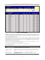
1
D-Link ™ DGS-3324SR
High-Density Layer 3 Stackable Gigabit Ethernet Switch
User’s Guide
D-Link DGS-3324SR Stackable Gigabit Ethernet Switch
____________________
Information in this document is subject to change without notice.
© 2004 D-Link Corporation. All rights reserved.
Reproduction in any manner whatsoever without the written permission of D-Link
Corporation is strictly forbidden.
Trademarks used in this text: D-Link, the D-LINK logo are trademarks of D-Link Computer Corporation; Microsoft and Windows are
registered trademarks of Microsoft Corporation.
Other trademarks and trade names may be used in this document to refer to either the entities claiming the marks and names or their products.
D-Link Computer Corporation disclaims any proprietary interest in trademarks and trade names other than its own.
February 2004 P/N 651GS3324025
ii
CONTENTS
D-Link ™ DGS-3324SR............................................................................................................ i
Intended Readers................................................................................................................................. ix
Typographical Conventions ................................................................................................................ ix
Notes, Notices, and Cautions ................................................................................................... x
Safety Instructions.................................................................................................................... x
Safety Cautions ................................................................................................................................................x
General Precautions for Rack-Mountable Products ...................................................................................... xii
Protecting Against Electrostatic Discharge .................................................................................................. xiii
Introduction .............................................................................................................................. 1
Switch Description............................................................................................................................... 1
Features ............................................................................................................................................................1
Front-Panel Components ..................................................................................................................... 2
LED Indicators .................................................................................................................................................2
Rear Panel Description ........................................................................................................................ 2
RPS Connector .................................................................................................................................................3
Management Options........................................................................................................................... 3
Web-based Management Interface ...................................................................................................................3
Command Line Console Interface Through the Serial Port or Telnet..............................................................3
SNMP-Based Management ..............................................................................................................................3
Installation ................................................................................................................................ 3
Package Contents................................................................................................................................. 3
Switch Installation ............................................................................................................................... 4
Installing the Switch Without the Rack............................................................................................................4
Installing the Switch in a Rack.........................................................................................................................4
Connecting Stacked Switch Groups..................................................................................................... 5
Configuring a Switch Group for Stacking........................................................................................................7
Unit ID Display for Switches in a Switch Stack ..............................................................................................8
Gigabit Combo Ports ........................................................................................................................... 8
External Redundant Power System...................................................................................................... 9
Connecting the Console Port ............................................................................................................. 10
Password Protection........................................................................................................................... 11
SNMP Settings................................................................................................................................... 12
Traps ............................................................................................................................................................................12
MIBs ............................................................................................................................................................................12
IP Address Assignment...................................................................................................................... 13
Connecting Devices to the Switch ..................................................................................................... 14
Introduction to Switch Management.................................................................................... 15
Introduction........................................................................................................................................ 15
Login to Web Manager ...................................................................................................................... 15
Web-based User Interface.................................................................................................................. 16
Areas of the User Interface.............................................................................................................................16
Web Pages......................................................................................................................................................17
Basic Setup ........................................................................................................................................ 18
Switch Information.........................................................................................................................................18
Switch IP Settings ..........................................................................................................................................18
Security IP Management Stations Configuration ...........................................................................................21
User Accounts Management ..........................................................................................................................21
Admin and User Privileges...........................................................................................................................................22
Saving Changes..............................................................................................................................................22
Factory Reset..................................................................................................................................................23
Restart System................................................................................................................................................24
Switch Information ............................................................................................................................ 24
Advanced Settings ............................................................................................................................. 25
Configuration.......................................................................................................................... 28
Configuring Box Information ............................................................................................................ 28
Configuring Ports............................................................................................................................... 29
Configuring Port Mirroring ............................................................................................................... 30
Configuring Link Aggregation .......................................................................................................... 31
Understanding Port Trunk Groups .................................................................................................................31
LACP Port Setting ............................................................................................................................. 34
Configuring IGMP............................................................................................................................. 36
IGMP Snooping .............................................................................................................................................36
Static Router Ports..........................................................................................................................................37
Configuring The Spanning Tree ........................................................................................................ 39
802.1w Rapid Spanning Tree .........................................................................................................................39
Port Transition States ...................................................................................................................................................39
802.1d/802.1w Compatibility.......................................................................................................................................40
STP Switch Settings .......................................................................................................................................40
STP Port Settings ...........................................................................................................................................41
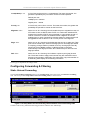
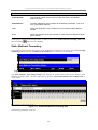
Configuring Forwarding & Filtering ................................................................................................. 43
Static Unicast Forwarding..............................................................................................................................43
Static Multicast Forwarding ...........................................................................................................................44
Configuring VLANs .......................................................................................................................... 45
Understanding IEEE 802.1p Priority..............................................................................................................45
VLANs ...........................................................................................................................................................46
Notes About VLANs on the DGS-3324SR ..................................................................................................................46
IEEE 802.1Q VLANs.....................................................................................................................................46
802.1Q VLAN Packet Forwarding...............................................................................................................................47
802.1Q VLAN Tags .....................................................................................................................................................47
Port VLAN ID..............................................................................................................................................................49
Tagging and Untagging................................................................................................................................................49
Ingress Filtering ...........................................................................................................................................................50
Default VLANs ............................................................................................................................................................50
Port-based VLANs .........................................................................................................................................50
VLAN Segmentation....................................................................................................................................................51
VLAN and Trunk Groups.............................................................................................................................................51
Configuring Static VLANs.............................................................................................................................51
GVRP Settings ...............................................................................................................................................53
Configuring Traffic Control (Broadcast/Multicast Storm Control) ................................................... 55
Configuring Port Security .................................................................................................................. 56
Configuring QoS................................................................................................................................ 58
Understanding QoS ........................................................................................................................................58
Setting Bandwidth Control.............................................................................................................................58
QoS Scheduling Mechanism Table ................................................................................................................60
QoS Output Scheduling..................................................................................................................................60
802.1p Default Priority...................................................................................................................................61
802.1p User Priority .......................................................................................................................................62
Configuring Traffic Segmentation .................................................................................................................63
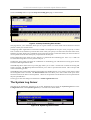
The System Log Server...................................................................................................................... 64
Configuring SNTP Settings ............................................................................................................... 66
Time Settings .................................................................................................................................................66
Time Zone and DST.......................................................................................................................................68
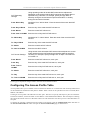
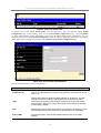
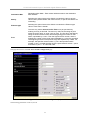
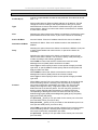
Configuring The Access Profile Table .............................................................................................. 69
Configuring The Port Access Entity .................................................................................................. 77
802.1X Port-based Network Access Control..................................................................................................77
Configure Authenticator.................................................................................................................................79
Configuring Local Users ................................................................................................................................82
PAE System Control ......................................................................................................................................82
Port Capability Settings................................................................................................................................................82
Initializing Ports ...........................................................................................................................................................84
Reauthenticate Port(s) ..................................................................................................................................................85
RADIUS Server .............................................................................................................................................86
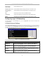
Configuring Layer 3 IP Networking .................................................................................................. 87
L3 Global Advanced Settings.........................................................................................................................87
Setting Up IP Interfaces .................................................................................................................................88
MD5 Key........................................................................................................................................................90
Route Redistribution Settings.........................................................................................................................90
Static/Default Route .......................................................................................................................................92
Static ARP Table............................................................................................................................................93
Routing Information Protocol (RIP)...............................................................................................................94
RIP Version 1 Message Format....................................................................................................................................95
RIP 1 Message..............................................................................................................................................................96
RIP 1 Route Interpretation ...........................................................................................................................................96
RIP Version 2 Extensions.............................................................................................................................................96
RIP2 Message Format ..................................................................................................................................................96
Setting Up RIP .............................................................................................................................................................97
Configuring OSPF..........................................................................................................................................99
General OSPF Settings...............................................................................................................................................112
OSPF Area Setting .....................................................................................................................................................113
OSPF Interface Configuration....................................................................................................................................114
OSPF Virtual Interface Settings .................................................................................................................................116
Area Aggregation Configuration................................................................................................................................118
OSPF Host Route Settings .........................................................................................................................................119
DHCP/BOOTP Relay...................................................................................................................................120
DHCP/BOOTP Relay Information.............................................................................................................................120
DHCP/BOOTP Relay Settings ...................................................................................................................................121
DNS Relay ...................................................................................................................................................121
Configuring DNS Relay Information .........................................................................................................................122
DNS Relay Static Table .............................................................................................................................................123
IP Multicasting .............................................................................................................................................123
IGMP Interface Configuration ...................................................................................................................................123
DVMRP Interface Configuration ...............................................................................................................................125
PIM_DM Interface Configuration..............................................................................................................................126
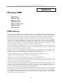
Managing SNMP .................................................................................................................. 129
SNMP Settings................................................................................................................................. 129
Traps ..........................................................................................................................................................................130
MIBs ..........................................................................................................................................................................130
SNMP User Table............................................................................................................................ 130
SNMP View Table........................................................................................................................... 132
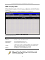
SNMP Group Table ......................................................................................................................... 134
SNMP Community Table Configuration ......................................................................................... 136
SNMP Host Table............................................................................................................................ 137
SNMP Engine ID ............................................................................................................................. 138
Monitoring ............................................................................................................................ 139
Port Utilization................................................................................................................................. 139
Packets ............................................................................................................................................. 140
Received(RX)...............................................................................................................................................141
UMB_cast(RX) ............................................................................................................................................143
Transmitted (TX) .........................................................................................................................................145
Errors ............................................................................................................................................... 147
Received (RX)..............................................................................................................................................147
Transmitted (TX) .........................................................................................................................................149
Size .................................................................................................................................................. 151
Stacking Information ....................................................................................................................... 153
Device Status ................................................................................................................................... 154
MAC Address .................................................................................................................................. 155
Switch History Log.......................................................................................................................... 156
IGMP Snooping Table ..................................................................................................................... 158
Browse Router Port.......................................................................................................................... 159
Port Access Control ......................................................................................................................... 159
Authenticator Statistics ................................................................................................................................159
Authenticator Session Statistics ...................................................................................................................161
Authenticator Diagnostics ............................................................................................................................162
Radius Authentication ..................................................................................................................................164
Radius Accounting .......................................................................................................................................166
Monitoring Layer 3 Features ........................................................................................................... 167
Browse IP Address .......................................................................................................................................167
Browse Routing Table..................................................................................................................................168
Browse ARP Table.......................................................................................................................................169
Browse IP Multicast Forwarding Table .......................................................................................................169
Browse IGMP Group Table .........................................................................................................................170
OSPF Monitoring .........................................................................................................................................170
OSPF LSDB Table .....................................................................................................................................................170
OSPF Neighbor Table ................................................................................................................................................171
OSPF Virtual Neighbor..............................................................................................................................................172
DVMRP Monitoring ....................................................................................................................................172
DVMRP Routing Table..............................................................................................................................................172
DVMRP Neighbor Address Table..............................................................................................................................173
DVMRP Routing Next Hop Table .............................................................................................................................173
PIM Monitoring ...........................................................................................................................................174
PIM Neighbor Address Table.....................................................................................................................................174
Switch Maintenance ............................................................................................................. 175
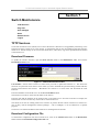
TFTP Services.................................................................................................................................. 175
Download Firmware.....................................................................................................................................175
Download Configuration File.......................................................................................................................175
Upload Configuration...................................................................................................................................176
Upload Log...................................................................................................................................................176
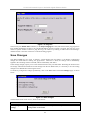
Ping Test .......................................................................................................................................... 176
Save Changes................................................................................................................................... 177
Reset ................................................................................................................................................ 178
Reboot Device.................................................................................................................................. 179
Logout.............................................................................................................................................. 179
Technical Specifications....................................................................................................... 180
Glossary................................................................................................................................. 182
D-Link DGS-3324SR Layer 3 Stackable Gigabit Ethernet Switch
Intended Readers
The DGS-3324SR User Guide contains information for setup and management of the DGS-3324SR Switch. This
guide is intended for network managers familiar with network management concepts and terminology.
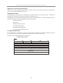
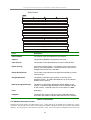
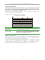
Typographical Conventions
Convention
Description
[]
In a command line, square brackets indicate an optional entry. For
example: [copy filename] means that optionally you can type copy
followed by the name of the file. Do not type the brackets.
Bold font
Indicates a button, a toolbar icon, menu, or menu item. For example:
Open the File menu and choose Cancel. Used for emphasis. May
also indicate system messages or prompts appearing on your
screen. For example: You have mail. Bold font is also used to
represent filenames, program names and commands. For example:
use the copy command.
Boldface Typewriter
Font
Indicates commands and responses to prompts that must be typed
exactly as printed in the manual.
Initial capital letter
Indicates a window name. Names of keys on the keyboard have
initial capitals. For example: Click Enter.
Italics
Indicates a window name or a field. Also can indicate a variables or
parameter that is replaced with an appropriate word or string. For
example: type filename means that you should type the actual
filename instead of the word shown in italic.
Menu Name > Menu Option
Menu Name > Menu Option
Indicates the menu structure.
Device > Port > Port Properties means the Port Properties menu
option under the Port menu option that is located under the Device
menu.
ix
D-Link DGS-3324SR Layer 3 Stackable Gigabit Ethernet Switch
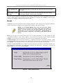
Notes, Notices, and Cautions
NOTE: A NOTE indicates important information that helps you make
better use of your device.
NOTICE: A NOTICE indicates either potential damage to hardware or loss
of data and tells you how to avoid the problem.
CAUTION: A CAUTION indicates a potential for property damage,
personal injury, or death.
Safety Instructions
Use the following safety guidelines to ensure your own personal safety and to help protect your system from
potential damage. Throughout this safety section, the caution icon (
) is used to indicate cautions and
precautions that you need to review and follow.
Safety Cautions
To reduce the risk of bodily injury, electrical shock, fire, and damage to the equipment, observe the following
precautions.
Observe and follow service markings. Do not service any product except as explained in your system
documentation. Opening or removing covers that are marked with the triangular symbol with a lightning bolt
may expose you to electrical shock. Components inside these compartments should be serviced only by a trained
service technician.
If any of the following conditions occur, unplug the product from the electrical outlet and replace the part or
contact your trained service provider:
– The power cable, extension cable, or plug is damaged.
– An object has fallen into the product.
– The product has been exposed to water.
– The product has been dropped or damaged.
– The product does not operate correctly when you follow the operating instructions.
•
Keep your system away from radiators and heat sources. Also, do not block cooling vents.
•
Do not spill food or liquids on your system components, and never operate the product in a wet
environment. If the system gets wet, see the appropriate section in your troubleshooting guide or contact
your trained service provider.
x
D-Link DGS-3324SR Layer 3 Stackable Gigabit Ethernet Switch
•
Do not push any objects into the openings of your system. Doing so can cause fire or electric shock by
shorting out interior components.
•
Use the product only with approved equipment.
•
Allow the product to cool before removing covers or touching internal components.
•
Operate the product only from the type of external power source indicated on the electrical ratings label.
If you are not sure of the type of power source required, consult your service provider or local power
company.
•
To help avoid damaging your system, be sure the voltage selection switch (if provided) on the power
supply is set to match the power available at your location:
– 115 volts (V)/60 hertz (Hz) in most of North and South America and some Far Eastern countries such
as South Korea and Taiwan
– 100 V/50 Hz in eastern Japan and 100 V/60 Hz in western Japan
– 230 V/50 Hz in most of Europe, the Middle East, and the Far East
•
Also be sure that attached devices are electrically rated to operate with the power available in your
location.
•
Use only approved power cable(s). If you have not been provided with a power cable for your system or
for any AC-powered option intended for your system, purchase a power cable that is approved for use in
your country. The power cable must be rated for the product and for the voltage and current marked on
the product's electrical ratings label. The voltage and current rating of the cable should be greater than
the ratings marked on the product.
•
To help prevent electric shock, plug the system and peripheral power cables into properly grounded
electrical outlets. These cables are equipped with three-prong plugs to help ensure proper grounding. Do
not use adapter plugs or remove the grounding prong from a cable. If you must use an extension cable,
use a 3-wire cable with properly grounded plugs.
•
Observe extension cable and power strip ratings. Make sure that the total ampere rating of all products
plugged into the extension cable or power strip does not exceed 80 percent of the ampere ratings limit
for the extension cable or power strip.
•
To help protect your system from sudden, transient increases and decreases in electrical power, use a
surge suppressor, line conditioner, or uninterruptible power supply (UPS).
•
Position system cables and power cables carefully; route cables so that they cannot be stepped on or
tripped over. Be sure that nothing rests on any cables.
•
Do not modify power cables or plugs. Consult a licensed electrician or your power company for site
modifications. Always follow your local/national wiring rules.
•
When connecting or disconnecting power to hot-pluggable power supplies, if offered with your system,
observe the following guidelines:
– Install the power supply before connecting the power cable to the power supply.
– Unplug the power cable before removing the power supply.
– If the system has multiple sources of power, disconnect power from the system by
unplugging all power cables from the power supplies.
•
Move products with care; ensure that all casters and/or stabilizers are firmly connected to the system.
Avoid sudden stops and uneven surfaces.
xi
D-Link DGS-3324SR Layer 3 Stackable Gigabit Ethernet Switch
General Precautions for Rack-Mountable Products
Observe the following precautions for rack stability and safety. Also refer to the rack installation documentation
accompanying the system and the rack for specific caution statements and procedures.
Systems are considered to be components in a rack. Thus, "component" refers to any system as well as to various
peripherals or supporting hardware.
CAUTION: Installing systems in a rack without the front and side stabilizers
installed could cause the rack to tip over, potentially resulting in bodily injury under
certain circumstances. Therefore, always install the stabilizers before installing
components in the rack.
After installing system/components in a rack, never pull more than one component
out of the rack on its slide assemblies at one time. The weight of more than one
extended component could cause the rack to tip over and may result in serious
injury.
•
Before working on the rack, make sure that the stabilizers are secured to the rack, extended to the floor,
and that the full weight of the rack rests on the floor. Install front and side stabilizers on a single rack or
front stabilizers for joined multiple racks before working on the rack.
Safety Instructions (continued)
Always load the rack from the bottom up, and load the heaviest item in the rack first.
Make sure that the rack is level and stable before extending a component from the rack.
Use caution when pressing the component rail release latches and sliding a component into or out of a rack; the
slide rails can pinch your fingers.
After a component is inserted into the rack, carefully extend the rail into a locking position, and then slide the
component into the rack.
Do not overload the AC supply branch circuit that provides power to the rack. The total rack load should not
exceed 80 percent of the branch circuit rating.
Ensure that proper airflow is provided to components in the rack.
Do not step on or stand on any component when servicing other components in a rack.
NOTE: A qualified electrician must perform all connections to DC power and to
safety grounds. All electrical wiring must comply with applicable local or national
codes and practices.
CAUTION: Never defeat the ground conductor or operate the equipment in the
absence of a suitably installed ground conductor. Contact the appropriate electrical
inspection authority or an electrician if you are uncertain that suitable grounding is
available.
xii
D-Link DGS-3324SR Layer 3 Stackable Gigabit Ethernet Switch
CAUTION: The system chassis must be positively grounded to the rack cabinet
frame. Do not attempt to connect power to the system until grounding cables are
connected. Completed power and safety ground wiring must be inspected by a
qualified electrical inspector. An energy hazard will exist if the safety ground cable
is omitted or disconnected.
Protecting Against Electrostatic Discharge
Static electricity can harm delicate components inside your system. To prevent static damage, discharge static
electricity from your body before you touch any of the electronic components, such as the microprocessor. You
can do so by periodically touching an unpainted metal surface on the chassis.
You can also take the following steps to prevent damage from electrostatic discharge (ESD):
1. When unpacking a static-sensitive component from its shipping carton, do not remove the component
from the antistatic packing material until you are ready to install the component in your system. Just
before unwrapping the antistatic packaging, be sure to discharge static electricity from your body.
2. When transporting a sensitive component, first place it in an antistatic container or packaging.
3. Handle all sensitive components in a static-safe area. If possible, use antistatic floor pads and
workbench pads and an antistatic grounding strap.
xiii
D-Link DGS-3324SR Layer 3 Stackable Gigabit Ethernet Switch
Section 1
Introduction
Switch Description
Features
Front-Panel Components
Back Panel Description
Plug-in Module Descriptions
Management Options
Switch Description
The DGS-3324SR is a modular Gigabit Ethernet backbone switch designed for adaptability and scalability. The
Switch provides a management platform and uplink to backbone for a stacked group of twelve DGS-3324SR
Layer 3 switches in a ring or chain topology arrangement. Alternatively, the Switch can utilize up to twenty-four
Gigabit Ethernet ports to function as a central distribution hub for other switches or switch groups, or routers.
The four built-in combination Gigabit ports have the option of being used as either 1000BASE-T or SFP Gigabit
connections.
Features
•
4 built-in combination 1000BASE-T/SFP ports
•
Ring or chain topology switch stacking configuration for up to 12 additional DGS-3324SR switches
•
88 Gbps switching fabric capacity
•
Supports 802.1D STP and 802.1w Rapid Spanning Tree for redundant back up bridge paths
•
Supports 802.1Q VLAN, IGMP snooping, 802.1p Priority Queues, port trunking, port mirroring
•
Multi-layer Access Control (based on MAC address, IP address, VLAN, Protocol, 802.1p, DSCP)
•
Supports Layer 3 functions including multiple IP Interfaces, MD5 Key Configuration, Route
Redistribution, Static and Default Route settings, Static ARP settings, RIP, OSPF, DNS Relay and IP
Multicast Routing Protocol.
•
Quality of Service (QoS) customized control
•
802.1x (port-based) access control and RADIUS Client support
•
Administrator-definable port security
•
Per-port bandwidth control
•
IEEE 802.3z and IEEE 802.3x compliant Flow Control for all Gigabit ports
•
SNMP v.1, v.2, v.3 network management, RMON support
•
Support optional external Redundant Power Supply
•
Supports Web-based management.
•
CLI management support
•
DHCP and BOOTP Client support.
•
Fully configurable either in-band or out-of-band control via RS-232 console serial connection.
•
Telnet remote control console
1
D-Link DGS-3324SR Layer 3 Stackable Gigabit Ethernet Switch
•
TFTP upgrade
•
Traffic Segmentation
•
SysLog support
•
Simple Network Time Protocol
•
Web GUI Traffic Monitoring
Front-Panel Components
The front panel of the Switch consists of LED indicators, an RS-232 communication port, and four SFP (MiniGBIC) combo ports.
Figure 1 - 1. Front Panel View of the switch
Comprehensive LED indicators display the status of the Switch and the network.
An RS-232 DCE console port for setting up and managing the Switch via a connection to a console terminal or
PC using a terminal emulation program.
LED Indicators
The LED indicators of the Switch include Power, Master, Console, RPS (Redundant Power Supply), 1000
Link/Act, Stack ID and SIO. A bank of 24 LEDs (2 for each port) indicates link, activity status and connection
speed for each port
Power
It will light green approximately 2 seconds after the switch is powered on to indicate
the ready state of the device.
Master
Lights steady green when the Switch is configured as the Master Switch in a stack.
Console
This indicator on the front panel should be lit during the Power-On Self Test (POST).
Lights green when the switch is being managed via out-of-band/local console
management through the RS-232 console port using a straight-through serial cable.
RPS
This indicator will light steady amber when an external power supply is supplying
power. This indicates the internal power supply has failed.
1000
Link/Act
Each on-board Gigabit Ethernet port has a corresponding indicator. This will light
steady green for a valid link and blink whenever there is reception or transmission
(i.e. Activity--Act) of data occurring at a port.
Stack ID
The switch includes a 7-segment LED (labeled STACK ID) to indicate the switch
status in a stacked switch group.
SIO
Indicates which stacking port, if any, is in use.
Rear Panel Description
The rear panel of the Switch contains an AC power connector, a connector for the Redundant Power Supply
(RPS) and two stacking ports.
2
D-Link DGS-3324SR Layer 3 Stackable Gigabit Ethernet Switch
Figure 1-2. Rear panel view of the Switch
The AC power connector is a standard three-pronged connector that supports the power cord. Plug the female
connector of the provided power cord into this socket, and the male side of the cord into a power outlet. The
Switch automatically adjusts its power setting to any supply voltage in the range from 100 ~ 240 VAC at 50 ~ 60
Hz.
RPS Connector
Connect the optional external redundant power supply to the RPS connector. If the Switch’s internal power unit
fails, the redundant power system automatically supplies power to the switch for uninterrupted operation.
The switch supports the D-Link RPS-500 redundant power supply units.
Management Options
The system may be managed out-of-band through the console port on the front panel or in-band using Telnet or a
web browser.
Web-based Management Interface
After you have successfully installed the Switch, you can configure the Switch, monitor the LED panel, and
display statistics graphically using a web browser, such as Netscape Navigator (version 6.2 and higher) or
Microsoft® Internet Explorer (version 5.0).
NOTE: To access the Switch through a web browser, the computer
running the web browser must have IP-based network access to the
switch.
Command Line Console Interface Through the Serial Port or Telnet
You can also connect a computer or terminal to the serial console port or use Telnet to access the Switch. The
command-line-driven interface provides complete access to all switch management features. For a full list of
commands, see the Command Line Interface Reference Manual, which is included on the documentation CD.
SNMP-Based Management
You can manage the Switch with an SNMP-compatible console program. The Switch is supports SNMP version
1.0, version 2.0 and version 3.0. The SNMP agent decodes the incoming SNMP messages and responds to
requests with MIB objects stored in the database. The SNMP agent updates the MIB objects to generate statistics
and counters.
The Switch supports a comprehensive set of MIB extensions:
•
RFC1213 MIB II
•
RFC1493 Bridge
•
RFC1643 Ether-like MIB
•
RFC1724 RIP 2
•
RFC1757 RMON
•
RFC1850 OSPF Version 2
3
D-Link DGS-3324SR Layer 3 Stackable Gigabit Ethernet Switch
•
RFC1907 (SNMPv2-MIB)
•
RFC2021 (RMON2)
•
RFC2096 IP Forwarding
•
RFC2233 Interface MIB
•
RFC2571 (SNMP Frameworks)
•
RFC2572 (Message Processing for SNMP)
•
RFC2573 (SNMP Applications)
•
RFC2574 (USM for SNMP)
•
RFC2575 (VACM for SNMP)
•
RFC2576 (Coexistence between SNMPs)
•
RFC2618 (Radius-Auth-Client-MIB)
•
RFC2620 (Radius-Acc-Client-MIB)
•
RFC2932 IPv4 Multicast Routing
•
RFC2933 IGMP
•
RFC2934 PIM
•
DVMRP MIB
•
D-Link Enterprise MIB
•
802.1p RFC2674
•
IEEE8021-PAE-MIB
•
RSTP-MIB
2
D-Link DGS-3324SR Layer 3 Stackable Gigabit Ethernet Switch
Section 2
Installation
Package Contents
Before You Connect to the Network
Switch Installation
Connecting Stacked Switch Groups
Gigabit Combo Ports
External Redundant Power System
Connecting the Console Port
Password Protection
SNMP Settings
IP Address Assignment
Connecting Devices to the Switch
Package Contents
Before you begin installing the Switch, confirm that your package contains the following items:
•
One DGS-3324SR Layer 3 Gigabit Switch
•
Mounting kit: 2 mounting brackets and screws
•
Four rubber feet with adhesive backing
•
One AC power cord
•
This User’s Guide with Registration Card
•
CLI Reference
•
CD-ROM with User’s Guide and CLI Reference
Before You Connect to the Network
NOTICE: Do not connect the Switch to the network until you have established the
correct IP settings.
Before you connect to the network, you must install the Switch on a flat surface or in a rack, set up a terminal
emulation program, plug in the power cord, and then set up a password and IP address.
The Switch is supplied with rubber feet for stationing it on a flat surface and mounting brackets and screws for
mounting the Switch in a rack.
NOTICE: Do not connect the stacked switch group to the network until you have
properly configured all switches for switch stacking. An improperly configured
switch stack can cause a broadcast storm.
3
D-Link DGS-3324SR Layer 3 Stackable Gigabit Ethernet Switch
Switch Installation
Installing the Switch Without the Rack
1.
Install the Switch on a level surface that can safely support the weight of the Switch and its attached
cables. The Switch must have adequate space for ventilation and for accessing cable connectors.
2.
Set the Switch on a flat surface and check for proper ventilation. Allow at least 5 cm (2 inches) on each
side of the Switch and 15 cm (6 inches) at the back for the power cable.
3.
Attach the rubber feet on the marked locations on the bottom of the chassis.
4.
The rubber feet, although optional, are recommended to keep the unit from slipping.
Figure 2-1. Install rubber feet for installations with or without a rack
Installing the Switch in a Rack
You can install the Switch in most standard 19-inch (48.3-cm) racks. Refer to the illustrations below.
1.
Use the supplied screws to attach a mounting bracket to each side of the Switch.
2.
Align the holes in the mounting bracket with the holes in the rack.
3.
Insert and tighten two screws through each of the mounting brackets.
Figure 2-2. Attach mounting brackets
4
D-Link DGS-3324SR Layer 3 Stackable Gigabit Ethernet Switch
Figure 2-3. Install switch in equipment rack
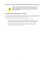
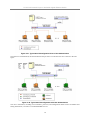
Connecting Stacked Switch Groups
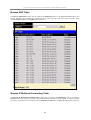
Up to 12 switches can be stacked together for Ring mode or Chain mode to a Master Unit or in tandem with a
second master unit via the second 10Gig stacking port. Users can add unit to reach maximum 288 GbE ports per
Ring stack or 168 GbE ports per Star stack. Switches are stacked together through a high-speed stack cables that
provide high speed of multiple Gigabit connections, allowing the entire stack to perform as a single IP entity.
User can see the number of switches stacked together from 7-segment display on front panel. Please refer to the
diagram below.
5
D-Link DGS-3324SR Layer 3 Stackable Gigabit Ethernet Switch
Figure 2-4. Ring (Bus) Topology
Please note that the DGS-3324SRi is needed to connect a group of Switches in the Star topology, as shown
below.
6
D-Link DGS-3324SR Layer 3 Stackable Gigabit Ethernet Switch
Figure 2-5. Star Topology Stacked Switch Group
The stacking ports are designated 1 and 2, and the stacking port being used will have its matching LED (on the
front panel) light a steady green when in use. Connection can be made from any stacking port to any other
stacking port. That is, stacking port 1 may connect to 1 or 2, and stacking port 2 may connect to 2 or 1
Configuring a Switch Group for Stacking
Follow the instructions below to configure the DGS-3324SR as the designated Master, and then to configure the
slave units.
To configure the DGS-3324SR to function in a stacked group as a master, do the following:
1. At the CLI login prompt, enter config box_priority current_box_id 1 priority 1
and press the Enter key. (Where the lowest priority number in a stack is always the Master, i.e. 2 would
have a higher priority than 5.)
2. Successful configuration will be verified by a Success message. It takes a few seconds for the change to
take effect. See the example below for the DGS-3324SR.
3. Be sure to save the configuration change using the CLI command save.
4. Reboot the Switch.
7
D-Link DGS-3324SR Layer 3 Stackable Gigabit Ethernet Switch
DGS-3324SR:4#config box_priority current_box_id 1 priority 1
Command: config box_priority current_box_id 1 priority 1
Success.
DGS-3324SR:4#............
DGS-3324SR:4#
To configure the same DGS-3324SR to function in a stacked group as the Slave, do the following:
1. At the CLI login prompt, enter config box_priority current_box_id 1 priority 2
and press the Enter key.
2. Successful configuration will be verified by a Success message. It takes a few seconds for the change to
take effect. See the example below for the DGS-3324SR.
3. Be sure to save the configuration change using the CLI command save.
DGS-3324SR:4#config box_priority current_box_id 1 priority 2
Command: config config box_priority current_box_id 1 priority 2
Success.
DGS-3324SR:4#...................................................................
NOTE: Make sure that each box has a different ID. No two boxes can
have the same ID.
Unit ID Display for Switches in a Switch Stack
The Stack ID. 7-segment LED (as shown below) on the front panel displays the Stack ID of the Switch. Please
also note that the Master LED is lit, indicating that this Switch is the Master unit in the stack.
Gigabit Combo Ports
In addition to the 24 10/100/1000 Mbps ports, the Switch features four Mini-GBIC Combo ports. These four
ports are 10/100/1000BASE-T copper ports (built-in) and Mini-GBIC ports (optional). Please note that the MiniGBIC ports are used instead of the built-in 10/100/1000BASE-T ports. The Mini-GBIC ports will not work
8
D-Link DGS-3324SR Layer 3 Stackable Gigabit Ethernet Switch
simultaneously with its corresponding 10/100/1000BASE-T port. For example, if port 24x is used on the Mini
GBIC module, port 24 is not available for the 10/100/1000BASE-T built-in port, and vice versa.
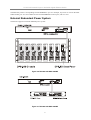
External Redundant Power System
The Switch supports an external redundant power system.
Figure 2-6. DPS-900 with DGS-3324SR
Figure 2-7. DPS-800 with DGS-3324SR
9
D-Link DGS-3324SR Layer 3 Stackable Gigabit Ethernet Switch
NOTE: See the DPS-900 documentation for more information.
CAUTION: Do not use the Switch with any redundant power system other
than the DPS-900.
Connecting the Console Port
The Switch provides an RS-232 serial port that enables a connection to a computer or terminal for monitoring
and configuring the switch. This port is a DB-9 connector, implemented as a DCE connection.
To use the console port, you need the following equipment:
•
A terminal or a computer with both a serial port and the ability to emulate a terminal
•
A RS-232 cable with a female DB-9 connector for the console port on the switch
To connect a terminal to the console port:
1. Connect the RS-232 cable directly to the console port on the Switch, and tighten the captive retaining
screws.
2. Connect the other end of the cable to a terminal or to the serial connector of a computer running
terminal emulation software. Set the terminal emulation software as follows:
1.
Select the appropriate serial port (COM port 1 or COM port 2).
3.
Set the data rate to 115200 baud.
4.
Set the data format to 8 data bits, 1 stop bit, and no parity.
5.
Set flow control to none.
6.
Under Properties, select VT100 for Emulation mode.
7.
Select Terminal keys for Function, Arrow, and Ctrl keys. Ensure that you select Terminal
keys (not Windows keys).
NOTICE: When you use HyperTerminal with the Microsoft® Windows® 2000
operating system, ensure that you have Windows 2000 Service Pack 2 or later
installed. Windows 2000 Service Pack 2 allows you to use arrow keys in
HyperTerminal’s VT100 emulation. See www.microsoft.com for information on
Windows 2000 service packs.
8. After you have correctly set up the terminal, plug the power cable into the power receptacle on
the back of the Switch. The boot sequence appears in the terminal.
9. After the boot sequence completes, the console login screen displays.
10. If you have not logged into the command line interface (CLI) program, press the Enter key at
the User name and password prompts. There is no default user name and password for the
Switch, user names and passwords must first be created by the administrator. If you have
previously set up user accounts, log in and continue to configure the Switch.
11. Enter the commands to complete your desired tasks. Many commands require administratorlevel access privileges. Read the next section for more information on setting up user accounts.
See the Command Line Reference on the documentation CD for a list of all commands and
additional information on using the CLI.
10
D-Link DGS-3324SR Layer 3 Stackable Gigabit Ethernet Switch
12. When you have completed your tasks, exit the session with the logout command or close the
emulator program.
Password Protection
The DGS-3324SR does not have a default user name and password. One of the first tasks when settings up the
Switch is to create user accounts. If you log in using a predefined administrator-level user name you have
privileged access to the Switch’s management software.
After your initial login, define new passwords for both default user names to prevent unauthorized access to the
Switch, and record the passwords for future reference.
To create an administrator-level account for the Switch, do the following:
1.
At the CLI login prompt, enter create account admin followed by the <user name> and press
the Enter key.
2.
You will be asked to provide a password. Type the <password> used for the administrator
account being created and press the Enter key.
3.
You will be prompted to enter the same password again to verify it. Type the same password
and press the Enter key.
4.
Successful creation of the new administrator account will be verified by a Success message.
User names and passwords can be up to 15 characters in length.
NOTE: Passwords
are case sensitive.
The sample below illustrates a successful creation of a new
administrator-level account with the user name “newmanager”.
DGS-3324SR:4#create account admin newmanager
Command: create account admin newmanager
Enter a case-sensitive new password:********
Enter the new password again for confirmation:********
Success.
DGS-3324SR:4#
NOTICE: CLI configuration commands only modify the running
configuration file and are not saved when the Switch is rebooted. To save
all your configuration changes in nonvolatile storage, you must use the
save command to copy the running configuration file to the startup
configuration.
11
D-Link DGS-3324SR Layer 3 Stackable Gigabit Ethernet Switch
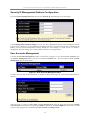
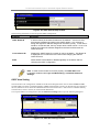
SNMP Settings
Simple Network Management Protocol (SNMP) is an OSI Layer 7 (Application Layer) function designed
specifically for managing and monitoring network devices. SNMP enables network management stations to read
and modify the settings of gateways, routers, switches, and other network devices. Use SNMP to configure
system features for proper operation, monitor performance and detect potential problems in the Switch, switch
group or network.
Managed devices that support SNMP include software (referred to as an agent), which runs locally on the device.
A defined set of variables (managed objects) is maintained by the SNMP agent and used to manage the device.
These objects are defined in a Management Information Base (MIB), which provides a standard presentation of
the information controlled by the on-board SNMP agent. SNMP defines both the format of the MIB
specifications and the protocol used to access this information over the network.
The DGS-3324SR supports the SNMP versions 1, 2c, and 3. You can specify which version of the SNMP you
want to use to monitor and control the Switch. The three versions of SNMP vary in the level of security
provided between the management station and the network device.
In SNMP v.1 and v.2, user authentication is accomplished using ‘community strings’, which function like
passwords. The remote user SNMP application and the switch SNMP must use the same community string.
SNMP packets from any station that has not been authenticated are ignored (dropped).
The default community strings for the Switch used for SNMP v.1 and v.2 management access are:
public - Allows authorized management stations to retrieve MIB objects.
private - Allows authorized management stations to retrieve and modify MIB objects.
SNMP v.3 uses a more sophisticated authentication process that is separated into two parts. The first part is to
maintain a list of users and their attributes that are allowed to act as SNMP managers. The second part describes
what each user on that list can do as an SNMP manager.
The Switch allows groups of users to be listed and configured with a shared set of privileges. The SNMP version
may also be set for a listed group of SNMP managers. Thus, you may create a group of SNMP managers that are
allowed to view read-only information or receive traps using SNMP v.1 while assigning a higher level of
security to another group, granting read/write privileges using SNMP v.3.
Using SNMP v.3 individual users or groups of SNMP managers can be allowed to perform or be restricted from
performing specific SNMP management functions. The functions allowed or restricted are defined using the
Object Identifier (OID) associated with a specific MIB. An additional layer of security is available for SNMP v.3
in that SNMP messages may be encrypted. To read more about how to configure SNMP v.3 settings for the
Switch read the next section.
Traps
Traps are messages that alert network personnel of events that occur on the Switch. The events can be as serious
as a reboot (someone accidentally turned OFF the Switch), or less serious like a port status change. The Switch
generates traps and sends them to the trap recipient (or network manager). Typical traps include trap messages
for Authentication Failure, Topology Change and Broadcast\Multicast Storm.
MIBs
Management and counter information are stored by the switch in the Management Information Base (MIB). The
Switch uses the standard MIB-II Management Information Base module. Consequently, values for MIB objects
can be retrieved from any SNMP-based network management software. In addition to the standard MIB-II, the
Switch also supports its own proprietary enterprise MIB as an extended Management Information Base. The
proprietary MIB may also be retrieved by specifying the MIB Object Identifier. MIB values can be either readonly or read-write.
12
D-Link DGS-3324SR Layer 3 Stackable Gigabit Ethernet Switch
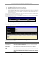
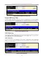
IP Address Assignment
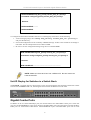
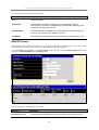
Each switch must be assigned its own IP Address, which is used for communication with an SNMP network
manager or other TCP/IP application (for example BOOTP, TFTP). The Switch’s default IP address is
10.90.90.90. You can change the default switch IP address to meet the specification of your networking address
scheme.
The Switch is also assigned a unique MAC address by the factory. This MAC address cannot be changed, and
can be found from the initial boot console screen – shown below.
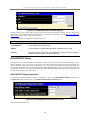
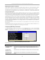
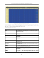
Figure 2 - 4. Boot Screen
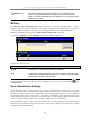
The Switch’s MAC address can also be found from the Web management program on the Switch Information
(Basic Settings) window on the Configuration menu.
The IP address for the Switch must be set before it can be managed with the Web-based manager. The Switch IP
address can be automatically set using BOOTP or DHCP protocols, in which case the actual address assigned to
the switch must be known.
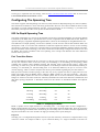
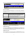
The IP address may be set using the Command Line Interface (CLI) over the console serial port as follows:
1.
Starting at the command line prompt, enter the commands config ipif System ipaddress
xxx.xxx.xxx.xxx/yyy.yyy.yyy.yyy. Where the x’s represent the IP address to be assigned to the IP
interface named System and the y’s represent the corresponding subnet mask.
2.
Alternatively, you can enter config ipif System ipaddress xxx.xxx.xxx.xxx/z. Where the x’s represent
the IP address to be assigned to the IP interface named System and the z represents the corresponding
number of subnets in CIDR notation.
The IP interface named System on the Switch can be assigned an IP address and subnet mask which can then be
used to connect a management station to the Switch’s Telnet or Web-based management agent.
Figure 2 - 5. Assigning the Switch an IP Address
In the above example, the Switch was assigned an IP address of 10.52.19.13 with a subnet mask of 255.0.0.0.
The system message Success indicates that the command was executed successfully. The Switch can now be
configured and managed via Telnet and the CLI or via the Web-based management.
13
D-Link DGS-3324SR Layer 3 Stackable Gigabit Ethernet Switch
Connecting Devices to the Switch
After assigning IP addresses to the Switch, you can connect devices to the Switch.
To connect a device to an SFP transceiver port:
1.
Use your cabling requirements to select an appropriate SFP transceiver type.
2.
Insert the SFP transceiver (sold separately) into the SFP transceiver slot.
3.
Use the appropriate network cabling to connect a device to the connectors on the SFP transceiver.
NOTICE: When the SFP transceiver acquires a link, the associated
integrated 10/100/1000BASE-T port is disabled.
14
D-Link DGS-3324SR Layer 3 Stackable Gigabit Ethernet Switch
Section 3
Introduction to Switch Management
Login to Web Manager
Web-based User Interface
Basic Setup
Switch Information
IP Address
User Accounts
Saving Changes
Factory Reset
Restart System
Introduction
All software functions of the DGS-3324SR can be managed, configured and monitored via the embedded webbased (HTML) interface. The switch can be managed from remote stations anywhere on the network through a
standard browser such as Netscape Navigator/Communicator or Microsoft Internet Explorer. The browser acts as
a universal access tool and can communicate directly with the Switch using the HTTP protocol.
The Web-based management module and the Console program (and Telnet) are different ways to access the same
internal switching software for configuration. Thus, all settings encountered in web-based management are the
same as those found in the console program.
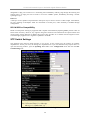
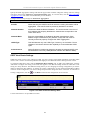
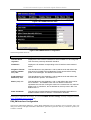
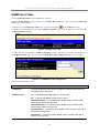
Login to Web Manager
To begin managing your Switch simply run the browser you have installed on your computer and point it to the
IP address you have defined for the device. The URL in the address bar should read something like:
http://123.123.123.123, where the numbers 123 represent the IP address of the switch.
NOTE: The Factory default IP address for the Switch is 10.90.90.90.
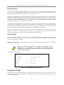
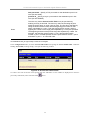
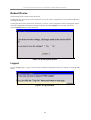
In the page that opens, click on the Login to make a setup button at the top of the window:
Figure 3- 1. Login Page
This opens the management module’s main page.
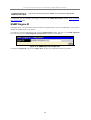
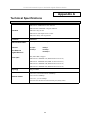
The switch management features available in the web-based manager are explained below.
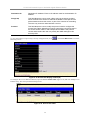
This opens the management module’s user authentication window, as seen below.
15
D-Link DGS-3324SR Layer 3 Stackable Gigabit Ethernet Switch
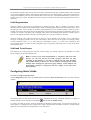
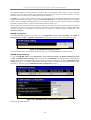
Figure 3- 2. Enter Network Password window
Leave both the User Name field and the Password field blank and click OK. This will open the Web-based user
interface. The Switch management features available in the web-based manager are explained below.
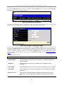
Web-based User Interface
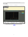
The user interface provides access to various switch configuration and management screens, allows you to view
performance statistics, and permits you to graphically monitor the system status.
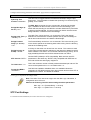
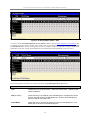
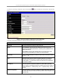
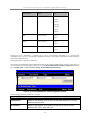
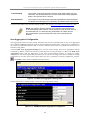
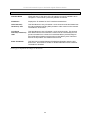
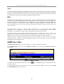
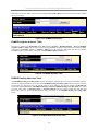
Areas of the User Interface
The figure below shows the user interface. The user interface is divided into 3 distinct areas as described in the
table.
Area 1
Area 3
Area 2
Figure 3- 3. Main Web-Manager Screen
16
D-Link DGS-3324SR Layer 3 Stackable Gigabit Ethernet Switch
Area
Function
1
Presents a graphical near real-time image of the front panel of the Switch. This area
displays the Switch’s ports and expansion modules, showing port activity, duplex
mode, or flow control, depending on the specified mode. To the right of the Switch’s
front panel is the current stacking configuration.
Various areas of the graphic can be selected for performing management functions,
including port configuration.
2
Select the menu or window to be displayed. The folder icons can be opened to
display the hyperlinked menu buttons and subfolders contained within them. Click
the D-Link logo to go to the D-Link website.
3
Presents switch information based on your selection and the entry of configuration
data.
NOTICE: Any changes made to the Switch configuration during the
current session must be saved in the Save Changes web menu
(explained below) or use the command line interface (CLI) command
save.
Web Pages
When you connect to the management mode of the Switch with a web browser, a login screen is displayed. Enter
a user name and password to access the Switch’s management mode.
Below is a list and description of the main folders available in the web interface:
Configuration folder: includes menus for port configuration, bandwidth control, link aggregation, port
mirroring, VLANs configuration, Spanning Tree Protocol setup, forwarding & filtering configuration, Quality of
Service, broadcast/multicast storm controls (Traffic Control), IGMP snooping, static router ports setup, SysLog
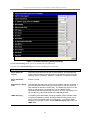
server setup, port security, SNTP settings and the access profile table. This also contains the Advanced Settings
menu which is used to configure miscellaneous settings such as for the serial port, MAC address aging time, and
to enable/disable the following: RMON, IGMP snooping, Telnet and web management access, traffic
segmentation, and 802.1x. The Switch Information page is used to enter system contact and physical location
information and lists basic information such as the switch’s MAC address, current firmware version and the
modules installed.
Security Management: contains 802.1x settings including RADIUS server information and PAE setup and
security management IP station setup.
SNMP Manager: contains menus for establishing the Switch IP settings, user accounts configuration and SNMP
setup including SNMP v.3 configuration.
Monitoring: includes menus for monitoring Switch performance monitors, MAC address table information,
router port information, IGMP Snooping information and 802.1x related information.
Maintenance: contains menus for upgrading firmware and saving configuration files (TFTP Services), saving
configuration changes, resetting and rebooting the Switch, Ping test and logging out of the web manager.
NOTE: Be sure to configure the user name and password in the User
Accounts menu before connecting the Switch to the greater network.
17
D-Link DGS-3324SR Layer 3 Stackable Gigabit Ethernet Switch
Basic Setup
The subsections below describe how to change some of the basic settings for the Switch such as changing IP
settings and assigning user names and passwords for management access privileges, as well as how to save the
changes and restart the Switch.
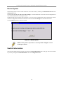
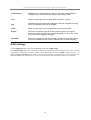
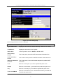
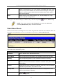
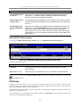
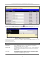
Switch Information
Click the Switch Information link in the Configuration menu.
Figure 3- 4. Switch Information – Basic Settings
The Switch Information window shows the Switch’s MAC Address (assigned by the factory and
unchangeable). In addition, the Boot PROM and Firmware Version numbers are shown. This information is
helpful to keep track of PROM and Firmware updates and to obtain the Switch’s MAC address for entry into
another network device’s address table – if necessary.
You may assign a System Name, System Location, and System Contact. If any changes or additions are made,
click Apply to implement them.
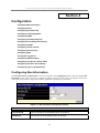
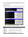
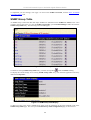
Switch IP Settings
Switch IP settings may initially be set using the console interface prior to connecting to it through the Ethernet. If
the Switch IP address has not yet been changed, read the Introduction of the CLI Reference or skip ahead to the
end of this section for a quick description of how to use the console port and CLI IP settings commands to
establish IP settings for the switch.
To change IP settings using the web manager you must access the IP Address menu located in the
Configuration folder.
To configure the Switch’s IP address:
Open the Configuration folder and click the IP Address link. The web manager will display the Switch IP
Settings menu below.
18
D-Link DGS-3324SR Layer 3 Stackable Gigabit Ethernet Switch
Figure 3- 5. Configure Switch IP Settings
NOTE: The Switch’s factory default IP address is 10.90.90.90 with a
subnet mask of 255.0.0.0 and a default gateway of 0.0.0.0.
To manually assign the Switch’s IP address, subnet mask, and default gateway address:
-Select Manual from the Get IP From drop-down menu.
-Enter the appropriate IP address and subnet mask.
-If you want to access the Switch from a different subnet from the one it is installed on, enter the IP address of
the gateway. If you will manage the Switch from the subnet on which it is installed, you can leave the default
address (0.0.0.0) in this field.
If no VLANs have been previously configured on the Switch, you can use the default VLAN Name “default”.
The default VLAN contains all of the Switch ports as members. If VLANs have been previously configured on
the Switch, you will need to enter the VLAN Name of the VLAN that contains the port connected to the
management station that will access the Switch. The Switch will allow management access from stations with the
same VLAN Name listed here.
To use the BOOTP or DHCP protocols to assign the switch an IP address, subnet mask, and default gateway
address:
Use the Get IP From: <Manual> pull-down menu to choose from BOOTP or DHCP. This selects how the
Switch will be assigned an IP address on the next reboot.
The Switch IP Settings options are:
Parameter
Description
BOOTP
The Switch will send out a BOOTP broadcast request when it is powered up.
The BOOTP protocol allows IP addresses, network masks, and default
gateways to be assigned by a central BOOTP server. If this option is set, the
Switch will first look for a BOOTP server to provide it with this information
before using the default or previously entered settings.
DHCP
The Switch will send out a DHCP broadcast request when it is powered up.
The DHCP protocol allows IP addresses, network masks, and default
gateways to be assigned by a DHCP server. If this option is set, the Switch
will first look for a DHCP server to provide it with this information before using
the default or previously entered settings.
Manual
Allows the entry of an IP address, Subnet Mask, and a Default Gateway for
the Switch. These fields should be of the form xxx.xxx.xxx.xxx, where each
xxx is a number (represented in decimal form) between 0 and 255. This
address should be a unique address on the network assigned for use by the
19
D-Link DGS-3324SR Layer 3 Stackable Gigabit Ethernet Switch
network administrator. The fields which require entries under this option are
as follows:
Subnet Mask
A Bitmask that determines the extent of the subnet that the Switch is on.
Should be of the form xxx.xxx.xxx.xxx, where each xxx is a number
(represented in decimal) between 0 and 255. The value should be 255.0.0.0
for a Class A network, 255.255.0.0 for a Class B network, and 255.255.255.0
for a Class C network, but custom subnet masks are allowed.
Default Gateway
IP address that determines where packets with a destination address outside
the current subnet should be sent. This is usually the address of a router or a
host acting as an IP gateway. If your network is not part of an intranet, or you
do not want the Switch to be accessible outside your local network, you can
leave this field unchanged.
VLAN Name
This allows the entry of a VLAN Name from which a management station will
be allowed to manage the switch using TCP/IP (in-band via web manager or
Telnet). Management stations that are on VLANs other than the one entered
in the VLAN Name field will not be able to manage the switch in-band unless
their IP addresses are entered in the Security IP Management menu. If
VLANs have not yet been configured for the switch, The default VLAN Name
contains all of the Switch’s ports. There are no entries in the Security IP
Management table, by default − so any management station that can connect
to the Switch can access the Switch until either a management VLAN is
specified or Management Station IP Addresses are assigned.
Setting the Switch’s IP Address using the Console Interface
Each Switch must be assigned its own IP Address, which is used for communication with an
SNMP network manager or other TCP/IP application (for example BOOTP, TFTP). The
Switch’s default IP address is 10.90.90.90. You can change the default Switch IP address to
meet the specification of your networking address scheme.
The IP address for the Switch must be set before it can be managed with the Web-based
manager. The Switch IP address can be automatically set using BOOTP or DHCP protocols, in
which case the actual address assigned to the Switch must be known.
The IP address may be set using the Command Line Interface (CLI) over the console serial port
as follows:
Starting at the command line prompt, enter the commands config ipif System ipaddress
xxx.xxx.xxx.xxx/yyy.yyy.yyy.yyy. Where the x’s represent the IP address to be assigned to the
IP interface named System and the y’s represent the corresponding subnet mask.
Alternatively, you can enter config ipif System ipaddress xxx.xxx.xxx.xxx/z. Where the x’s
represent the IP address to be assigned to the IP interface named System and the z represents
the corresponding number of subnets in CIDR notation.
The IP interface named System on the Switch can be assigned an IP address and subnet mask
which can then be used to connect a management station to the Switch’s Telnet or Web-based
management agent.
The system message Success indicates that the command was executed successfully. The
Switch can now be configured and managed via Telnet and the CLI or via the Web-based
management agent using the above IP address to connect to the Switch.
20
D-Link DGS-3324SR Layer 3 Stackable Gigabit Ethernet Switch
Security IP Management Stations Configuration
Go to the Security Management folder and click on Security IP; the following screen will appear.
Figure 3- 6. Security IP Management Setup
Use the Management Station IP Settings to select up to three management stations used to manage the Switch.
If you choose to define one or more designated management stations, only the chosen stations, as defined by IP
address, will be allowed management privilege through the web manager or Telnet session. To define a
management station IP setting, type in the IP address and click on the Apply button.
User Accounts Management
Use the User Accounts Management window to control user privileges. To view existing User Accounts, open
the Security Management folder and click on the User Accounts link. This will open the User Account
Management page, as shown below.
Figure 3- 7. User Accounts Management Table
To add a new user, click on the Add button. To modify or delete an existing user, click on the Modify button for
that user.
Figure 3- 8. Add User Accounts Modify Table
Add a new user by typing in a User Name, and New Password and retype the same password in the Confirm
New Password. Choose the level of privilege (Admin or User) from the Access Right drop-down menu. To add
a user account using the CLI commands use create account and config account.
21
D-Link DGS-3324SR Layer 3 Stackable Gigabit Ethernet Switch
Figure 3- 9. Modify User Accounts
Modify or delete an existing user account in the User Account Modify Table. To delete the user account, click
on the Delete button. To change the password, type in the New Password and retype it in the Confirm New
Password entry field. Choose the level of privilege (Admin or User) from the Access Right drop-down menu.
To delete a user account using CLI use the command delete account. To change an existing account use config
account.
Admin and User Privileges
There are two levels of user privileges: Admin and User. Some menu selections available to users with Admin
privileges may not be available to those with User privileges.
The following table summarizes the Admin and User privileges:
Management
Admin
User
Configuration
Yes
Read Only
Network Monitoring
Yes
Read Only
Community Strings and Trap Stations
Yes
Read Only
Update Firmware and Configuration Files
Yes
No
System Utilities
Yes
Ping Only
Factory Reset
Yes
No
Add/Update/Delete User Accounts
Yes
No
View User Accounts
Yes
No
User Account Management
Admin and User Privileges
After establishing a User Account with Admin-level privileges, be sure to save the changes (see below).
Saving Changes
Changes made to the Switch’s configuration must be saved in order to retain them. Access the Save
Configuration by clicking the Save Changes button located in the Maintenance folder.
22
D-Link DGS-3324SR Layer 3 Stackable Gigabit Ethernet Switch
Figure 3- 10. Save Configuration window
The Switch has two levels of memory, normal RAM and non-volatile or NV-RAM. To save all the changes
made in the current session to the Switch’s flash memory, click the Save Configuration button. Click the OK
button in the new dialog box that appears to continue. When this is done, the settings will be immediately applied
to the switching software in RAM, and will immediately take effect. Once the Switch configuration settings have
been saved to NV-RAM, they become the default settings for the Switch. These settings will be used every time
the Switch is rebooted.
Some settings, though, require you to restart the Switch before they will take effect. Restarting the Switch erases
all settings in RAM and reloads the stored settings from the NV-RAM. Thus, it is necessary to save all setting
changes to NV-RAM before rebooting the Switch.
To save settings using CLI the command is save.
Factory Reset
Click the Reset link in the Maintenance folder to bring up the reset menu.
Figure 3- 11. Factory Reset to Default Value window
Reset − returns all configuration settings except the Switch’s IP address, subnet mask, default gateway, log, user
account and stack information settings to the factory default settings.
Reset Config − returns all configuration settings except the stack information settings to the factory default
settings, but does not save the settings or reboot the Switch. If you select this option the switch configuration will
be returned to the factory default settings for the current session only. When the Switch is rebooted, it will return
to the last configuration saved to the switch’s NV-RAM using the Save Changes option.
Reset System − returns the switch configuration to the factory default settings and then saves the factory default
configuration to the Switch’s NV-RAM. The Switch will then reboot. When the Switch has rebooted, it will have
the same configuration as when it was delivered from the factory.
23
D-Link DGS-3324SR Layer 3 Stackable Gigabit Ethernet Switch
Restart System
The following menu is used to restart the Switch. Access this menu by clicking on the Reboot Device link in the
Maintenance folder.
Click the Yes after Do you want to save the settings? to instruct the Switch to save the current configuration to
non-volatile RAM before restarting the Switch.
Clicking the No option instructs the Switch not to save the current configuration before restarting the Switch.
All of the configuration information entered since the last time Save Changes was executed will be lost.
Click the Restart button to restart the Switch.
Figure 3- 12. Restart System
NOTE: Clicking Yes is equivalent to executing Save Changes and then
restarting the Switch.
Switch Information
The first page displayed upon logging in presents the System Information menu. This page can be accessed at
any time by clicking the Switch Information link in the Configuration folder.
24
D-Link DGS-3324SR Layer 3 Stackable Gigabit Ethernet Switch
Figure 3- 13. Switch Information
The System Information page displays general information about the Switch including its MAC Address,
Hardware Boot PROM and Firmware versions, and other optional information.
You can also enter or change a System Name, System Location, and the name and telephone number of the
responsible administrator in the System Contact. It is recommended that the person responsible for the
maintenance of the network system be listed here. Click on the Apply button to make the changes effective.
To view this information using Telnet use CLI command show switch.
Advanced Settings
The Advanced Settings window contains the main settings for all major functions for the Switch. To view the
Advanced Settings window, click its link in the Configuration folder. This will enable the following window to
be viewed and configured.
25
D-Link DGS-3324SR Layer 3 Stackable Gigabit Ethernet Switch
Figure 3- 14. Switch Information − Advanced Settings
The Advanced Settings menu options are summarized in the table below.
Variables in the Advanced Settings menu of the Web Manager are as follows:
Parameter
Description
Serial Port Auto
Logout
Select the logout time used for the console interface. This automatically
logs the user out after an idle period of time as defined. Choose from the
following options: 2 Minutes, 5 Minutes, 10 Minutes, 15 Minutes or Never.
Serial Port Baud
Rate
Fixed at 115200.
MAC Address Aging
Time
This field specifies the length of time a learned MAC Address will remain in
the forwarding table without being accessed (that is, how long a learned
MAC Address is allowed to remain idle). The default age-out time for the
Switch is 300 seconds. To change this, type in a different value
representing the MAC address age-out time in seconds. The Aging Time
can be set to any value between 10 and 1,000,000 seconds.
IGMP Snooping
To enable system-wide IGMP Snooping capability select Enabled. IGMP
snooping is Disabled by default. Enabling IGMP snooping allows you to
specify use of a multicast router only (see below). To configure IGMP
Snooping for individual VLANs, use the IGMP Snooping page under the
IGMP folder.
26
D-Link DGS-3324SR Layer 3 Stackable Gigabit Ethernet Switch
Multicast Router
Only
If this option is enabled and IGMP Snooping is also enabled, the Switch
forwards all multicast traffic to a multicast-enabled router only. Otherwise,
the Switch will forward all multicast traffic to any IP router.
GVRP Status
Use this pull-down menu to Enable or Disable GVRP on the Switch.
Telnet Status
Telnet configuration is Enabled by default. If you do not want to allow
configuration of the system through Telnet choose Disabled.
Web Status
Web-based management is Enabled by default. If you choose to disable
this by selecting Disabled, you will lose the ability to configure the system
through the web interface as soon as these settings are applied.
RMON Status
Remote monitoring (RMON) of the Switch is Enabled or Disabled here.
Link Aggregation
Algorithm
The algorithm that the Switch uses to balance the load across the ports
that make up the port trunk group is defined by this definition. Choose
MAC Source, MAC Destination, MAC Src & Dest, IP Source, IP
Destination or IP Src & Dest (See the Link Aggregation section of this
manual).
Switch 802.1x
Enables or disables 802.1x; default is Disabled.
Auth Protocol
The user may choose between Local and Radius Eap.
HOL Prevention
Enables or disables HOL (Head of Line) prevention; default is Enabled.
Jumbo Frame
Enables or disables Jumbo Frame acceptance; default is Disabled.
Syslog State
Enables or disables Syslog State; default is Disabled.
27
D-Link DGS-3324SR Layer 3 Stackable Gigabit Ethernet Switch
Section 4
Configuration
Configuring Box Information
Configuring Ports
Configuring Port Mirroring
Configuring Link Aggregation
Configuring IGMP
Configuring The Spanning Tree
Configuring Forwarding and Filtering
Configuring VLANs
Configuring Traffic Control
Configuring Port Security
Configuring QoS
The System Log Server
Configuring SNTP Settings
Configuring The Access Profile Table
Configuring The Port Access Entity
Configuring Layer 3 IP Networking
Configuring Box Information
The Box Information Configuration screen can be found in the Configuration folder under the heading Box
Information. This window is used to configure the Master switch of a switch stack. The Master switch is the
switch that will be used to configure the software applications regarding the switch stack.
Figure 4- 1. Box Information Configuration window
Parameter
Description
Current Box ID
The current Box ID of the Master switch in the stack.
New Box ID
The new box ID of the Master switch in the stack.
28
D-Link DGS-3324SR Layer 3 Stackable Gigabit Ethernet Switch
Box Type
The user may choose the model name of the Master switch in a stack to be
the main configuring switch of that stack.
Priority
Displays the priority ID of the Switch. The lower the number, the higher the
priority. The box (switch) with the lowest priority number in the stack is the
Master switch.
Information configured in this screen may be found in the Monitoring folder under Stack Information.
Configuring Ports
This section contains information for configuring various attributes and properties for individual physical ports,
including port speed and flow control. Clicking on Port Configurations in the Configuration menu will display
the following window for the user:
Figure 4- 2. Port Configuration menu
29
D-Link DGS-3324SR Layer 3 Stackable Gigabit Ethernet Switch
To configure switch ports:
1.
Choose the Unit from the pull-down menu.
2.
Choose the port or sequential range of ports using the From…To… port pull-down menus.
3.
Use the remaining pull-down menus to configure the parameters described below:
Parameter
Description
State <Enabled>
Toggle the State <Enabled> field to either enable or disable a given port or
group of ports.
Speed/Duplex
<Auto>
Toggle the Speed/Duplex <Auto> field to either select the speed and
duplex/half-duplex state of the port. Auto – auto-negotiation between 10 and
1000 Mbps devices, full- or half-duplex. The Auto setting allows the port to
automatically determine the fastest settings the device the port is connected
to can handle, and then to use those settings. The other options are Auto,
10M/Half, 10M/Full, 100M/Half, 100M/Full, 1000M/Full_M (master), and
1000M/Full_S (slave). There is no automatic adjustment of port settings with
any option other than Auto.
Flow Control
Displays the flow control scheme used for the various port configurations.
Ports configured for full-duplex use 802.3x flow control, half-duplex ports use
backpressure flow control, and Auto ports use an automatic selection of the
two. The default is Disabled.
Learning
Enable or disable MAC address learning for the selected ports. When
Enabled, destination and source MAC addresses are automatically listed in
the forwarding table. When learning is Disabled, MAC addresses must be
manually entered into the forwarding table. This is sometimes done for
reasons of security or efficiency. See the section on Forwarding/Filtering for
information on entering MAC addresses into the forwarding table.
Click Apply to implement the new settings on the Switch.
Configuring Port Mirroring
The Switch allows you to copy frames transmitted and received on a port and redirect the copies to another port.
You can attach a monitoring device to the mirrored port, such as a sniffer or an RMON probe, to view details
about the packets passing through the first port. This is useful for network monitoring and troubleshooting
purposes. To view the Setup Port Mirroring window, click Port Mirroring in the Configuration folder.
30
D-Link DGS-3324SR Layer 3 Stackable Gigabit Ethernet Switch
Figure 4- 3. Setup Port Mirroring window
To configure a mirror port:
1.
Select the Source Port from where you want to copy frames and the Target Port, which receives the
copies from the source port.
2.
Select the Source Direction, Ingress, Egress, or Both and change the Status drop-down menu to
Enabled.
3.
Click Apply to let the changes take effect.
NOTE: You cannot mirror a fast port onto a slower port. For example, if
you try to mirror the traffic from a 100 Mbps port onto a 10 Mbps port, this
can cause throughput problems. The port you are copying frames from
should always support an equal or lower speed than the port to which you
are sending the copies. Also, the target port for the mirroring cannot be a
member of a trunk group. Please note a target port and a source port
cannot be the same port.
Configuring Link Aggregation
Understanding Port Trunk Groups
Port trunk groups are used to combine a number of ports together to make a single high-bandwidth data pipeline.
The DGS-3324SR supports up to 32 port trunk groups with 2 to 8 ports in each group. A potential bit rate of
8000 Mbps can be achieved.
31
D-Link DGS-3324SR Layer 3 Stackable Gigabit Ethernet Switch
Figure 4- 4. Example of Port Trunk Group
The Switch treats all ports in a trunk group as a single port. Data transmitted to a specific host (destination
address) will always be transmitted over the same port in a trunk group. This allows packets in a data stream to
arrive in the same order they were sent.
Note: If any ports within the trunk group become disconnected, packets
intended for the disconnected port will be load shared among the other
uplinked ports of the link aggregation group.
Link aggregation allows several ports to be grouped together and to act as a single link. This gives a bandwidth
that is a multiple of a single link’s bandwidth.
Link aggregation is most commonly used to link a bandwidth intensive network device or devices, such as a
server, to the backbone of a network.
The Switch allows the creation of up to 32 link aggregation groups, each group consisting of 2 to 8 links (ports).
The aggregated links must be contiguous (they must have sequential port numbers) except the two (optional)
Gigabit ports, which can only belong to a single link aggregation group. All of the ports in the group must be
members of the same VLAN, and their STP status, static multicast, traffic control, traffic segmentation, 802.1p
default priority configurations must be identical. Port locking , port mirroring and 802.1X must not be enabled
on the trunk group. Further, the aggregated links must all be of the same speed and should be configured as fullduplex.
The Master Port of the group is to be configured by the user, and all configuration options, including the VLAN
configuration, that can be applied to the Master Port are applied to the entire link aggregation group.
Load balancing is automatically applied to the ports in the aggregated group, and a link failure within the group
causes the network traffic to be directed to the remaining links in the group.
The Spanning Tree Protocol will treat a link aggregation group as a single link, on the switch level. On the port
level, the STP will use the port parameters of the Master Port in the calculation of port cost and in determining
32
D-Link DGS-3324SR Layer 3 Stackable Gigabit Ethernet Switch
the state of the link aggregation group. If two redundant link aggregation groups are configured on the switch,
STP will block one entire group, in the same way STP will block a single port that has a redundant link.
To configure port trunking, click on the Link Aggregation hyperlink in the Configuration folder to bring up the
Current Link Aggregation Group Entries table:
Figure 4- 5. Current Link Aggregation Group Entries window
To configure port trunk groups, click the Add button to add a new trunk group and use the menu Link
Aggregation Group Configuration menu (see example below) to set up trunk groups. To modify a port trunk
group, double-click on it to bring up the Link Aggregation Group Configuration menu. To delete a port trunk
group, click the corresponding
table.
under the Delete heading in the Current Link Aggregation Group Entries
Figure 4- 6. Link Aggregation Group Configuration window – Add
33
D-Link DGS-3324SR Layer 3 Stackable Gigabit Ethernet Switch
Figure 4- 7. Link Aggregation Group Configuration window – Modify
The user-changeable parameters are as follows:
Parameter
Description
Group ID
Select an ID number for the group, between 1 and 32.
Type
This pull-down menu allows you to select between Static and LACP (Link
Aggregation Control Protocol.) LACP allows for the automatic detection of
links in a Port Trunking Group.
State
Trunk groups can be toggled between Enabled and Disabled. This is used
to turn a port trunking group on or off. This is useful for diagnostics, to
quickly isolate a bandwidth intensive network device or to have an absolute
backup aggregation group that is not under automatic control.
Master Port
Choose the Master port for the trunk group.
Unit
Choose the number representing the Switch in the stack for which you
would like to configure a Link Aggregation Group for.
Choose Member
Ports
Choose the members of a trunked group. Up to 8 ports per group can be
assigned to a group.
Flooding Port
A trunking group must designate one port to allow transmission of
broadcasts and unknown unicasts.
After setting the previous parameters, click Apply to allow your changes to be implemented. Successfully created
trunk groups will be show in the Current Link Aggregation Group Entries as seen in Figure 4-5.
LACP Port Setting
The LACP Port Setting window is used in conjunction with the Link Aggregation window to create port trunking
groups on the Switch. Using the following window, the user may set which ports will be active and passive in
processing and sending LACP control frames.
34
D-Link DGS-3324SR Layer 3 Stackable Gigabit Ethernet Switch
Figure 4- 8. LACP Port Setting and Information window
The user may set the following parameters:
Parameter
Description
Unit
Choose the number representing the Switch in the stack for which you
would like to change the LACP Port mode.
From/To
A consecutive group of ports may be configured starting with the selected
port.
Mode
Active – Active LACP ports are capable of processing and sending LACP
control frames. This allows LACP compliant devices to negotiate the
aggregated link so the group may be changed dynamically as needs require.
In order to utilize the ability to change an aggregated port group, that is, to
add or subtract ports from the group, at least one of the participating devices
must designate LACP ports as active. Both devices must support LACP.
Passive – LACP ports that are designated as passive cannot initially send
LACP control frames. In order to allow the linked port group to negotiate
adjustments and make changes dynamically, at one end of the connection
must have “active” LACP ports (see above).
35
D-Link DGS-3324SR Layer 3 Stackable Gigabit Ethernet Switch
After setting the previous parameters, click Apply to allow your changes to be implemented. The LACP Port
Information Table shows which ports are active and/or passive.
Configuring IGMP
Internet Group Management Protocol (IGMP) snooping allows the Switch to recognize IGMP queries and
reports sent between network stations or devices and an IGMP host. When enabled for IGMP snooping, the
Switch can open or close a port to a specific device based on IGMP messages passing through the Switch.
In order to use IGMP Snooping it must first be enabled for the entire Switch (see Advanced Settings). You may
then fine-tune the settings for each VLAN using the IGMP Snooping link in the Configuration folder. When
enabled for IGMP snooping, the Switch can open or close a port to a specific Multicast group member based on
IGMP messages sent from the device to the IGMP host or vice versa. The Switch monitors IGMP messages and
discontinues forwarding multicast packets when there are no longer hosts requesting that they continue.
IGMP Snooping
Use the Current IGMP Snooping Group Entries window to view IGMP Snooping settings. To modify the
settings, click the Modify button of the VLAN ID you want to change.
Figure 4- 9. Current IGMP Snooping Group Entries
Clicking the Modify button will bring up the IGMP Snooping Settings menu.
Figure 4- 10. IGMP Snooping Settings window
36
D-Link DGS-3324SR Layer 3 Stackable Gigabit Ethernet Switch
The following parameters may be viewed or modified:
Parameter
VLAN ID
Description
This is the VLAN ID that, along with the VLAN name, identifies the VLAN
which the user wishes to modify the IGMP Snooping Settings for.
VLAN Name
This is the VLAN Name that, along with the VLAN ID, identifies the
VLAN which the user wishes to modify the IGMP Snooping Settings for.
Query Interval
The Query Interval field is used to set the time (in seconds) between
transmitting IGMP queries. Entries between 1 and 9,999 seconds are
allowed. Default = 125.
Max Response Time
Robustness Variable
This determines the maximum amount of time in seconds allowed before
sending an IGMP response report. The Max Response Time field allows
an entry between 1 and 25 (seconds). Default = 10.
Adjust this variable according to expected packet loss. If packet loss on
the VLAN is expected to be high, the Robustness Variable should be
increased to accommodate increased packet loss. This entry field allows
an entry of 1 to 255. Default = 2.
Last Member Query
Interval
Specifies the maximum amount of time between group-specific query
messages, including those sent in response to leave group messages.
Default = 1.
Host Timeout
This is the maximum amount of time in seconds allowed for a host to
continue membership in a multicast group without the Switch receiving a
host membership report. Default = 260.
Route Timeout
This is the maximum amount of time in seconds a route is kept in the
forwarding table without receiving a membership report. Default = 260.
Leave Timer
This specifies the maximum amount of time in seconds between the
Switch receiving a leave group message from a host, and the Switch
issuing a group membership query. If no response to the membership
query is received before the Leave Timer expires, the (multicast)
forwarding entry for that host is deleted.
Querier State
Choose Enabled to enable transmitting IGMP Query packets or Disabled
to disable. The default value is Disabled.
State
Select Enabled to implement IGMP Snooping. This field is Disabled by
default.
Click Apply to implement the new settings, Click the Show All IGMP Group Entries link to return to the
Current IGMP Snooping Group Entries window.
Static Router Ports
A static router port is a port that has a multicast router attached to it. Generally, this router would have a
connection to a WAN or to the Internet. Establishing a router port will allow multicast packets coming from the
router to be propagated through the network, as well as allowing multicast messages (IGMP) coming from the
network to be propagated to the router.
37
D-Link DGS-3324SR Layer 3 Stackable Gigabit Ethernet Switch
A router port has the following behavior:
•
All IGMP Report packets will be forwarded to the router port.
•
IGMP queries (from the router port) will be flooded to all ports.
•
All UDP multicast packets will be forwarded to the router port. Because routers do not send IGMP
reports or implement IGMP snooping, a multicast router connected to the router port of the Layer 3
switch would not be able to receive UDP data streams unless the UDP multicast packets were all
forwarded to the router port.
A router port will be dynamically configured when IGMP query packets, RIPv2 multicast, DVMRP multicast,
PIM-DM multicast packets are detected flowing into a port.
Open the IGMP folder and the click on the Static Router Ports Entry link to open the Current Static Router
Ports Entries page, as shown below.
Figure 4- 11. Current Static Router Ports Entries window
The Current Static Router Ports Entries page (shown above) displays all of the current entries to the Switch’s
static router port table. To add or modify an entry, click the Modify button. This will open the Static Router
Ports Settings page, as shown below.
Figure 4- 12. Static Router Ports Settings window
The following parameters can be set:
Parameter
Description
VID (VLAN ID)
This is the VLAN ID that, along with the VLAN name, identifies the VLAN
where the multicast router is attached.
VLAN Name
This is the name of the VLAN where the multicast router is attached.
Unit
This is the Unit ID of the Switch in a switch stack for which you are creating
an entry into the Switch’s static router port table.
Member Ports
There are the ports on the switch that will have a multicast router attached
to them.
38
D-Link DGS-3324SR Layer 3 Stackable Gigabit Ethernet Switch
Click Apply to implement the new settings, Click the Show All Static Router Port Entries link to return to the
Current Static Router Port Entries window.
Configuring The Spanning Tree
The Switch supports 802.1d Spanning Tree Protocol (STP) and 802.1w Rapid Spanning Tree Protocol (RSTP).
802.1d STP will be familiar to most networking professionals. However since 802.1w RSTP has been recently
introduced to D-Link managed Ethernet switches, a brief introduction to the technology is provided below
followed by a description of how to set up 802.1 d STP and 802.1w RSTP.
802.1w Rapid Spanning Tree
The Switch implements two versions of the Spanning Tree Protocol, the Rapid Spanning Tree Protocol (RSTP)
as defined by the IEEE 802.1w specification and a version compatible with the IEEE 802.1d STP. RSTP can
operate with legacy equipment implementing IEEE 802.1d, however the advantages of using RSTP will be lost.
The IEEE 802.1w Rapid Spanning Tree Protocol (RSTP) evolved from the 802.1d STP standard. RSTP was
developed in order to overcome some limitations of STP that impede the function of some recent switching
innovations, in particular, certain Layer 3 function that are increasingly handled by Ethernet switches. The basic
function and much of the terminology is the same as STP. Most of the settings configured for STP are also used
for RSTP. This section introduces some new Spanning Tree concepts and illustrates the main differences
between the two protocols.
Port Transition States
An essential difference between the two protocols is in the way ports transition to a forwarding state and the in
the way this transition relates to the role of the port (forwarding or not forwarding) in the topology. RSTP
combines the transition states disabled, blocking and listening used in 802.1d and creates a single state
Discarding. In either case, ports do not forward packets; in the STP port transition states disabled, blocking or
listening or in the RSTP port state discarding there is no functional difference, the port is not active in the
network topology. Table 5-7 below compares how the two protocols differ regarding the port state transition.
Both protocols calculate a stable topology in the same way. Every segment will have a single path to the root
bridge. All bridges listen for BPDU packets. However, BPDU packets are sent more frequently – with every
Hello packet. BPDU packets are sent even if a BPDU packet was not received. Therefore, each link between
bridges are sensitive to the status of the link. Ultimately this difference results faster detection of failed links, and
thus faster topology adjustment. A drawback of 802.1d is this absence of immediate feedback from adjacent
bridges.
802.1d STP
802.1w RSTP
Forwarding?
Learning?
Disabled
Discarding
No
No
Blocking
Discarding
No
No
Listening
Discarding
No
No
Learning
Learning
No
Yes
Forwarding
Forwarding
Yes
Yes
Table 4- 1. Comparing Port States
RSTP is capable of more rapid transition to a forwarding state – it no longer relies on timer configurations –
RSTP compliant bridges are sensitive to feedback from other RSTP compliant bridge links. Ports do not need to
wait for the topology to stabilize before transitioning to a forwarding state. In order to allow this rapid transition,
the protocol introduces two new variables: the edge port and the point-to-point (P2P) port.
Edge Port
The edge port is a configurable designation used for a port that is directly connected to a segment where a loop
cannot be created. An example would be a port connected directly to a single workstation. Ports that are
39
D-Link DGS-3324SR Layer 3 Stackable Gigabit Ethernet Switch
designated as edge ports transition to a forwarding state immediately without going through the listening and
learning states. An edge port loses its status if it receives a BPDU packet, immediately becoming a normal
spanning tree port.
P2P Port
A P2P port is also capable of rapid transition. P2P ports may be used to connect to other bridges. Under RSTP,
all ports operating in full-duplex mode are considered to be P2P ports, unless manually overridden through
configuration.
802.1d/802.1w Compatibility
RSTP can interoperate with legacy equipment and is capable of automatically adjusting BPDU packets to 802.1d
format when necessary. However, any segment using 802.1 STP will not benefit from the rapid transition and
rapid topology change detection of RSTP. The protocol also provides for a variable used for migration in the
event that legacy equipment on a segment is updated to use RSTP.
STP Switch Settings
The Spanning Tree Protocol (STP) operates on two levels: on the switch level, the settings are globally
implemented. On the port level, the settings are implemented on a per user-defined Group of ports basis. To
open the following window, open the Spanning Tree folder in the Configuration menu and click the STP
Switch Settings link.
Figure 4- 13. STP Switch Settings
40
D-Link DGS-3324SR Layer 3 Stackable Gigabit Ethernet Switch
Configure the following parameters and click the Apply button to implement them:
Parameter
Description
Spanning Tree
Protocol <Disabled>
This field can be toggled between Enabled and Disabled using the pulldown menu. This will enable or disable the Spanning Tree Protocol (STP),
globally, for the switch.
Bridge Max Age: (6 40 sec) <20 >
The Max. Age can be set from 6 to 40 seconds. At the end of the Max.
Age, if a BPDU has still not been received from the Root Bridge, your
Switch will start sending its own BPDU to all other Switches for permission
to become the Root Bridge. If it turns out that your Switch has the lowest
Bridge Identifier, it will become the Root Bridge.
Bridge Hello Time: (1
- 10 sec) < 2 >
The Hello Time can be set from 1 to 10 seconds. This is the interval
between two transmissions of BPDU packets sent by the Root Bridge to
tell all other Switches that it is indeed the Root Bridge.
Bridge Forward
Delay: (4 - 30 sec)
<15 >
The Forward Delay can be from 4 to 30 seconds. This is the time any port
on the Switch spends in the listening state while moving from the blocking
state to the forwarding state.
Bridge Priority: (0 61440) <32768>
A Priority for the switch can be set from 0 to 61440. This number is used
in the voting process between switches on the network to determine which
switch will be the root switch. A low number indicates a high priority, and a
high probability that this switch will be elected as the root switch.
STP Version<RSTP >
Choose RSTP (default) or STP Compatibility. Both versions use STP
parameters in the same way. RSTP is fully compatible with IEEE 802.1d
STP and will function with legacy equipment.
Tx Hold Count <3 >
This is the maximum number of Hello packets transmitted per interval. The
count can be specified from 1 to 10. Default value = 3.
Forwarding BPDU
<Enabled >
This field can enabled or disabled. When it is enabled it allows the
forwarding of STP BPDU packets from other network devices when STP is
disabled on the switch. The default is enabled.
Click Apply to implement the changes made.
Note: The Hello Time cannot be longer than the Max. Age. Otherwise, a
configuration error will occur.
Observe the following formulas when setting the above parameters:
Max. Age ≤ 2 x (Forward Delay - 1 second)
Max. Age ≥ 2 x (Hello Time + 1 second)
STP Port Settings
For stacked switch installations, first select the Unit to be configured.
41
D-Link DGS-3324SR Layer 3 Stackable Gigabit Ethernet Switch
Figure 4- 14. STP Port Settings
In addition to setting Spanning Tree parameters for use on the switch level, the Switch allows for the
configuration of groups of ports, each port-group of which will have its own spanning tree, and will require some
of its own configuration settings. An STP Group will use the switch-level parameters entered above, with the
addition of Port Priority and Port Cost.
An STP Group spanning tree works in the same way as the switch-level spanning tree, but the root bridge
concept is replaced with a root port concept. A root port is a port of the group that is elected on the basis of port
priority and port cost, to be the connection to the network for the group. Redundant links will be blocked, just as
redundant links are blocked on the switch level.
The STP on the switch level blocks redundant links between switches (and similar network devices). The port
level STP will block redundant links within an STP Group.
It is advisable to define an STP Group to correspond to a VLAN group of ports.
The following fields can be set:
Parameter
Description
Unit
This is the Unit ID of a switch in a switch stack.
From/To < Port 1 >
A consecutive group of ports may be configured starting with the selected
port.
State < Disabled >
This drop-down menu allows you to Enable or Disable STP for the
selected group of ports.
42
D-Link DGS-3324SR Layer 3 Stackable Gigabit Ethernet Switch
Cost(0=Auto) < 0 >
A Port Cost can be set from 1 to 200000000. The lower the number, the
greater the probability the port will be chosen to forward packets.
Default port cost:
100Mbps port = 200000
Gigabit ports = 20000
Priority <0>
A Port Priority can be from 0 to 240. The lower the number, the greater the
probability the port will be chosen as the Root Port.
Migration <No>
Select Yes or No. Choosing Yes will enable the port to migrate from 802.1d
STP status to 802.1w RSTP status. RSTP can coexist with standard STP,
however the benefits of RSTP are not realized on a port where an 802.1d
network connects to an 802.1w enabled network. Migration should be
enabled (yes) on ports connected to network stations or segments that will
be upgraded to 802.1w RSTP on all or some portion of the segment.
Edge <No>
Select Yes or No. Choosing Yes designates the port as an edge port. Edge
ports cannot create loops, however an edge port can lose edge port status
if a topology change creates a potential for a loop. An edge port normally
should not receive BPDU packets. If a BPDU packet is received it
automatically loses edge port status. No indicates the port does not have
edge port status.
P2P <No>
Select Yes or No. Choosing Yes indicates a point-to-point (p2p) shared
link. These are similar to edge ports however they are restricted in that a
p2p port must operate in full duplex. Like edge ports, p2p ports transition to
a forwarding state rapidly thus benefiting from RSTP.
Click Apply to implement the changes made.
Configuring Forwarding & Filtering
Static Unicast Forwarding
Open the Forwarding & Filtering folder in the Configuration menu and click on the Unicast Forwarding
link. This will open the Setup Static Unicast Forwarding Table, as shown below:
Figure 4- 15. Setup Static Unicast Forwarding Table and Static Unicast Forwarding Table
To add or edit an entry, define the following parameters and then click Add/Modify:
43
D-Link DGS-3324SR Layer 3 Stackable Gigabit Ethernet Switch
Parameter
Description
VLAN ID (VID)
The VLAN ID number of the VLAN on which the above Unicast MAC
address resides.
MAC Address
The MAC address to which packets will be statically forwarded. This must
be a unicast MAC address.
Unit
Allows the designation of the module on which the above MAC address
resides.
Port
Allows the selection of the port number on which the MAC address entered
above resides.
Click Apply to implement the changes made. To delete an entry in the Static Unicast Forwarding Table, click
the corresponding
under the Delete heading.
Static Multicast Forwarding
The following figure and table describe how to set up Multicast forwarding on the switch. Open the Forwarding
& Filtering folder and click on the Multicast Forwarding link to see the entry screen below:
Figure 4- 16. Static Multicast Forwarding Settings and Current Multicast Forwarding Entries
The Static Multicast Forwarding Settings page displays all of the entries made into the Switch’s static
multicast forwarding table. Click the Add button to open the Setup Static Multicast Forwarding Table, as
shown below:
Figure 4- 17. Setup Static Multicast Forwarding Table
The following parameters can be set:
44
D-Link DGS-3324SR Layer 3 Stackable Gigabit Ethernet Switch
Parameter
Description
Unit
This is the Unit ID of a switch in a switch stack.
VID
The VLAN ID of the VLAN the corresponding MAC address belongs to.
Multicast MAC
Address
The MAC address of the static source of multicast packets. This must be a
multicast MAC address.
Allows the selection of ports that will be members of the static multicast
group and ports that are either forbidden from joining dynamically, or that
can join the multicast group dynamically, using GMRP.
Port Settings
The options are:
None – no restrictions on the port dynamically joining the multicast group.
When None is chosen, the port will not be a member of the Static Multicast
Group.
Egress – the port is a static member of the multicast group.
Click Apply to implement the changes made. To delete an entry in the Static Multicast Forwarding Table, click
the corresponding
under the Delete heading. Click the Show All Multicast Forwarding Entries link to return
to the Static Multicast Forwarding Settings window.
Configuring VLANs
Understanding IEEE 802.1p Priority
Priority tagging is a function defined by the IEEE 802.1p standard designed to provide a means of managing
traffic on a network where many different types of data may be transmitted simultaneously. It is intended to
alleviate problems associated with the delivery of time critical data over congested networks. The quality of
applications that are dependent on such time critical data, such as video conferencing, can be severely and
adversely affected by even very small delays in transmission.
Network devices that are in compliance with the IEEE 802.1p standard have the ability to recognize the priority
level of data packets. These devices can also assign a priority label or tag to packets. Compliant devices can also
strip priority tags from packets. This priority tag determines the packet’s degree of expeditiousness and
determines the queue to which it will be assigned.
Priority tags are given values from 0 to 7 with 0 being assigned to the lowest priority data and 7 assigned to the
highest. The highest priority tag 7 is generally only used for data associated with video or audio applications,
which are sensitive to even slight delays, or for data from specified end users whose data transmissions warrant
special consideration.
The Switch allows you to further tailor how priority tagged data packets are handled on your network. Using
queues to manage priority tagged data allows you to specify its relative priority to suit the needs of your network.
There may be circumstances where it would be advantageous to group two or more differently tagged packets
into the same queue. Generally, however, it is recommended that the highest priority queue, Queue 1, be
reserved for data packets with a priority value of 7. Packets that have not been given any priority value are
placed in Queue 0 and thus given the lowest priority for delivery.
A weighted round robin system is employed on the Switch to determine the rate at which the queues are emptied
of packets. The ratio used for clearing the queues is 4:1. This means that the highest priority queue, Queue 1, will
clear 4 packets for every 1 packet cleared from Queue 0.
45
D-Link DGS-3324SR Layer 3 Stackable Gigabit Ethernet Switch
Remember, the priority queue settings on the Switch are for all ports, and all devices connected to the Switch
will be affected. This priority queuing system will be especially beneficial if your network employs switches
with the capability of assigning priority tags.
VLANs
A Virtual Local Area Network (VLAN) is a network topology configured according to a logical scheme rather
than the physical layout. VLANs can be used to combine any collection of LAN segments into an autonomous
user group that appears as a single LAN. VLANs also logically segment the network into different broadcast
domains so that packets are forwarded only between ports within the VLAN. Typically, a VLAN corresponds to
a particular subnet, although not necessarily.
VLANs can enhance performance by conserving bandwidth, and improve security by limiting traffic to specific
domains.
A VLAN is a collection of end nodes grouped by logic instead of physical location. End nodes that frequently
communicate with each other are assigned to the same VLAN, regardless of where they are physically on the
network. Logically, a VLAN can be equated to a broadcast domain, because broadcast packets are forwarded to
only members of the VLAN on which the broadcast was initiated.
Notes About VLANs on the DGS-3324SR
No matter what basis is used to uniquely identify end nodes and assign these nodes VLAN membership, packets
cannot cross VLANs without a network device performing a routing function between the VLANs.
The DGS-3324SR supports IEEE 802.1Q VLANs and Port-Based VLANs. The port untagging function can be
used to remove the 802.1Q tag from packet headers to maintain compatibility with devices that are tag-unaware.
The Switch’s default is to assign all ports to a single 802.1Q VLAN named “default.”
The “default” VLAN has a VID = 1.
The member ports of Port-based VLANs may overlap, if desired.
IEEE 802.1Q VLANs
Some relevant terms:
Tagging – The act of putting 802.1Q VLAN information into the header of a packet.
Untagging – The act of stripping 802.1Q VLAN information out of the packet header.
Ingress port – A port on a switch where packets are flowing into the switch and VLAN decisions must be made.
Egress port – A port on a switch where packets are flowing out of the switch, either to another switch or to an
end station, and tagging decisions must be made.
IEEE 802.1Q (tagged) VLANs are implemented on the Switch. 802.1Q VLANs require tagging, which enables
them to span the entire network (assuming all switches on the network are IEEE 802.1Q-compliant).
VLANs allow a network to be segmented in order to reduce the size of broadcast domains. All packets entering a
VLAN will only be forwarded to the stations (over IEEE 802.1Q enabled switches) that are members of that
VLAN, and this includes broadcast, multicast and unicast packets from unknown sources.
VLANs can also provide a level of security to your network. IEEE 802.1Q VLANs will only deliver packets
between stations that are members of the VLAN.
46
D-Link DGS-3324SR Layer 3 Stackable Gigabit Ethernet Switch
Any port can be configured as either tagging or untagging. The untagging feature of IEEE 802.1Q VLANs
allows VLANs to work with legacy switches that don’t recognize VLAN tags in packet headers. The tagging
feature allows VLANs to span multiple 802.1Q-compliant switches through a single physical connection and
allows Spanning Tree to be enabled on all ports and work normally.
The IEEE 802.1Q standard restricts the forwarding of untagged packets to the VLAN the receiving port is a
member of.
The main characteristics of IEEE 802.1Q are as follows:
•
Assigns packets to VLANs by filtering.
•
Assumes the presence of a single global spanning tree.
•
Uses an explicit tagging scheme with one-level tagging.
802.1Q VLAN Packet Forwarding
Packet forwarding decisions are made based upon the following three types of rules:
•
Ingress rules – rules relevant to the classification of received frames belonging to a VLAN.
•
Forwarding rules between ports – decides whether to filter or forward the packet.
•
Egress rules – determines if the packet must be sent tagged or untagged.
Figure 4- 18. IEEE 802.1Q Packet Forwarding
802.1Q VLAN Tags
The figure below shows the 802.1Q VLAN tag. There are four additional octets inserted after the source MAC
address. Their presence is indicated by a value of 0x8100 in the EtherType field. When a packet’s EtherType
47
D-Link DGS-3324SR Layer 3 Stackable Gigabit Ethernet Switch
field is equal to 0x8100, the packet carries the IEEE 802.1Q/802.1p tag. The tag is contained in the following
two octets and consists of 3 bits of user priority, 1 bit of Canonical Format Identifier (CFI – used for
encapsulating Token Ring packets so they can be carried across Ethernet backbones), and 12 bits of VLAN ID
(VID). The 3 bits of user priority are used by 802.1p. The VID is the VLAN identifier and is used by the 802.1Q
standard. Because the VID is 12 bits long, 4094 unique VLANs can be identified.
The tag is inserted into the packet header making the entire packet longer by 4 octets. All of the information
originally contained in the packet is retained.
Figure 4- 19. IEEE 802.1Q Tag
The EtherType and VLAN ID are inserted after the MAC source address, but before the original
EtherType/Length or Logical Link Control. Because the packet is now a bit longer than it was originally, the
Cyclic Redundancy Check (CRC) must be recalculated.
Figure 4- 20. Adding an IEEE 802.1Q Tag
48
D-Link DGS-3324SR Layer 3 Stackable Gigabit Ethernet Switch
Port VLAN ID
Packets that are tagged (are carrying the 802.1Q VID information) can be transmitted from one 802.1Q
compliant network device to another with the VLAN information intact. This allows 802.1Q VLANs to span
network devices (and indeed, the entire network, if all network devices are 802.1Q compliant).
Unfortunately, not all network devices are 802.1Q compliant. These devices are referred to as tag-unaware.
802.1Q devices are referred to as tag-aware.
Prior to the adoption of 802.1Q VLANs, port-based and MAC-based VLANs were in common use. These
VLANs relied upon a Port VLAN ID (PVID) to forward packets. A packet received on a given port would be
assigned that port’s PVID and then be forwarded to the port that corresponded to the packet’s destination address
(found in the Switch’s forwarding table). If the PVID of the port that received the packet is different from the
PVID of the port that is to transmit the packet, the Switch will drop the packet.
Within the Switch, different PVIDs mean different VLANs (remember that two VLANs cannot communicate
without an external router). So, VLAN identification based upon the PVIDs cannot create VLANs that extend
outside a given switch (or switch stack).
Every physical port on a switch has a PVID. 802.1Q ports are also assigned a PVID, for use within the Switch. If
no VLANs are defined on the Switch, all ports are then assigned to a default VLAN with a PVID equal to 1.
Untagged packets are assigned the PVID of the port on which they were received. Forwarding decisions are
based upon this PVID, in so far as VLANs are concerned. Tagged packets are forwarded according to the VID
contained within the tag. Tagged packets are also assigned a PVID, but the PVID is not used to make packet
forwarding decisions, the VID is.
Tag-aware switches must keep a table to relate PVIDs within the Switch to VIDs on the network. The Switch
will compare the VID of a packet to be transmitted to the VID of the port that is to transmit the packet. If the two
VIDs are different, the switch will drop the packet. Because of the existence of the PVID for untagged packets
and the VID for tagged packets, tag-aware and tag-unaware network devices can coexist on the same network.
A switch port can have only one PVID, but can have as many VIDs as the Switch has memory in its VLAN table
to store them.
Because some devices on a network may be tag-unaware, a decision must be made at each port on a tag-aware
device before packets are transmitted – should the packet to be transmitted have a tag or not? If the transmitting
port is connected to a tag-unaware device, the packet should be untagged. If the transmitting port is connected to
a tag-aware device, the packet should be tagged.
Tagging and Untagging
Every port on an 802.1Q compliant switch can be configured as tagging or untagging.
Ports with tagging enabled will put the VID number, priority and other VLAN information into the header of all
packets that flow into and out of it. If a packet has previously been tagged, the port will not alter the packet, thus
keeping the VLAN information intact. The VLAN information in the tag can then be used by other 802.1Q
compliant devices on the network to make packet-forwarding decisions.
Ports with untagging enabled will strip the 802.1Q tag from all packets that flow into and out of those ports. If
the packet doesn’t have an 802.1Q VLAN tag, the port will not alter the packet. Thus, all packets received by
and forwarded by an untagging port will have no 802.1Q VLAN information. (Remember that the PVID is only
used internally within the switch). Untagging is used to send packets from an 802.1Q-compliant network device
to a non-compliant network device.
49
D-Link DGS-3324SR Layer 3 Stackable Gigabit Ethernet Switch
Ingress Filtering
A port on a switch where packets are flowing into the switch and VLAN decisions must be made is referred to as
an ingress port. If ingress filtering is enabled for a port, the switch will examine the VLAN information in the
packet header (if present) and decide whether or not to forward the packet.
If the packet is tagged with VLAN information, the ingress port will first determine if the ingress port itself is a
member of the tagged VLAN. If it is not, the packet will be dropped. If the ingress port is a member of the
802.1Q VLAN, the switch then determines if the destination port is a member of the 802.1Q VLAN. If it is not,
the packet is dropped. If the destination port is a member of the 802.1Q VLAN, the packet is forwarded and the
destination port transmits it to its attached network segment.
If the packet is not tagged with VLAN information, the ingress port will tag the packet with its own PVID as a
VID (if the port is a tagging port). The switch then determines if the destination port is a member of the same
VLAN (has the same VID) as the ingress port. If it does not, the packet is dropped. If it has the same VID, the
packet is forwarded and the destination port transmits it on its attached network segment.
This process is referred to as ingress filtering and is used to conserve bandwidth within the Switch by dropping
packets that are not on the same VLAN as the ingress port at the point of reception. This eliminates the
subsequent processing of packets that will just be dropped by the destination port.
Default VLANs
The Switch initially configures one VLAN, VID = 1, called “default.” The factory default setting assigns all
ports on the Switch to the “default.” As new VLANs are configured in Port-based mode, their respective member
ports are removed from the “default.”
Packets cannot cross VLANs. If a member of one VLAN wants to connect to another VLAN, the link must be
through an external router.
Note: If no VLANs are configured on the Switch, then all packets will be
forwarded to any destination port. Packets with unknown source
addresses will be flooded to all ports. Broadcast and multicast packets will
also be flooded to all ports.
An example is presented below:
VLAN Name
VID
Switch Ports
System (default)
1
5, 6, 7, 8, 21, 22, 23, 24
Engineering
2
9, 10, 11, 12
Marketing
3
13, 14, 15, 16
Finance
4
17, 18, 19, 20
Sales
5
1, 2, 3, 4
Table 4- 2. VLAN Example – Assigned Ports
Port-based VLANs
Port-based VLANs limit traffic that flows into and out of switch ports. Thus, all devices connected to a port are
members of the VLAN(s) the port belongs to, whether there is a single computer directly connected to a switch,
or an entire department.
50
D-Link DGS-3324SR Layer 3 Stackable Gigabit Ethernet Switch
On port-based VLANs, NICs do not need to be able to identify 802.1Q tags in packet headers. NICs send and
receive normal Ethernet packets. If the packet’s destination lies on the same segment, communications take place
using normal Ethernet protocols. Even though this is always the case, when the destination for a packet lies on
another switch port, VLAN considerations come into play to decide if the packet gets dropped by the switch or
delivered.
VLAN Segmentation
Take for example a packet that is transmitted by a machine on Port 1 that is a member of VLAN 2. If the
destination lies on another port (found through a normal forwarding table lookup), the switch then looks to see if
the other port (Port 10) is a member of VLAN 2 (and can therefore receive VLAN 2 packets). If Port 10 is not a
member of VLAN 2, then the packet will be dropped by the switch and will not reach its destination. If Port 10 is
a member of VLAN 2, the packet will go through. This selective forwarding feature based on VLAN criteria is
how VLANs segment networks. The key point being that Port 1 will only transmit on VLAN 2.
Network resources such as printers and servers however, can be shared across VLANs. This is achieved by
setting up overlapping VLANs. That is ports can belong to more than one VLAN group. For example, setting
VLAN 1 members to ports 1, 2, 3, and 4 and VLAN 2 members to ports 1, 5, 6, and 7. Port 1 belongs to two
VLAN groups. Ports 8, 9, and 10 are not configured to any VLAN group. This means ports 8, 9, and 10 are in the
same VLAN group.
VLAN and Trunk Groups
The members of a trunk group have the same VLAN setting. Any VLAN setting on the members of a trunk
group will apply to the other member ports.
Note: In order to use VLAN segmentation in conjunction with port trunk
groups, you can first set the port trunk group(s), and then you may
configure VLAN settings. If you wish to change the port trunk grouping
with VLANs already in place, you will not need to reconfigure the VLAN
settings after changing the port trunk group settings. VLAN settings will
automatically change in conjunction with the change of the port trunk
group settings.
Configuring Static VLANs
To create or modify an 802.1Q VLAN:
In the Configuration folder, open the VLAN folder and click the Static VLAN Entry link to open the following
window:
Figure 4- 21. Current 802.1Q Static VLANs Entries window
The 802.1Q Static VLANs menu lists all previously configured VLANs by VLAN ID and name. To delete an
existing 802.1Q VLAN, click the corresponding
button under the Delete heading.
To create a new 802.1Q VLAN, click the Add button in the Static VLANs menu. A new menu will appear, as
shown below, to configure the port settings and to assign a unique name and number to the new VLAN. See the
table below for a description of the parameters in the new menu.
51
D-Link DGS-3324SR Layer 3 Stackable Gigabit Ethernet Switch
Figure 4- 22. 802.1Q Static VLANs – Add
To return to the Current 802.1Q Static VLANs Entries window, click the Show All Static VLAN Entries link.
To change an existing 802.1Q VLAN entry, double-click on the selected entry in the Current 802.1Q Static
VLANs Entries menu. A new menu appears, use this to configure the port settings and to assign a unique name
and number to the new VLAN. See the table below for a description of the parameters in the new menu.
Figure 4- 23. 802.1Q Static VLANs Entry Settings – Modify
The following fields can then be set in either the Add or Modify 802.1Q Static VLANs menus:
Parameter
Description
Unit
Displays the Unit ID of the switch − within the switch stack − that the VLAN
will be created on.
VID (VLAN ID)
Allows the entry of a VLAN ID in the Add dialog box, or displays the VLAN
ID of an existing VLAN in the Edit dialog box. VLANs can be identified by
either the VID or the VLAN name.
VLAN Name
Allows the entry of a name for the new VLAN in the Add dialog box, or for
editing the VLAN name in the Edit dialog box.
52
D-Link DGS-3324SR Layer 3 Stackable Gigabit Ethernet Switch
Advertisement
Enabling this function will allow the switch to send out GVRP packets to
outside sources, notifying that they may join the existing VLAN.
Port
Allows an individual port to be specified as member of a VLAN.
Tag
Specifies the port as either 802.1Q tagging or 802.1Q untagged. Checking
the box will designate the port as Tagged.
None
Allows an individual port to be specified as a non-VLAN member.
Egress
Select this to specify the port as a static member of the VLAN. Egress
member ports are ports that will be transmitting traffic for the VLAN. These
ports can be either tagged or untagged.
Forbidden
Select this to specify the port as not being a member of the VLAN and that
the port is forbidden from becoming a member of the VLAN dynamically.
GVRP Settings
In the Configuration menu, open the VLANs folder and click GVRP Setting.
The GVRP Settings dialog box, shown below, allows you to determine whether the Switch will share its VLAN
configuration information with other GARP VLAN Registration Protocol (GVRP) enabled switches. In
addition, Ingress Checking can be used to limit traffic by filtering incoming packets whose PVID does not
match the PVID of the port. Results can be seen in the table under the configuration settings, as seen below.
53
D-Link DGS-3324SR Layer 3 Stackable Gigabit Ethernet Switch
Figure 4- 24. GVRP Settings and GVRP Table
The following fields can be set:
Parameter
Description
Unit
Displays the Unit ID of the switch − within the switch stack − that the VLAN
will be created on.
From/To
These two fields allow you to specify the range of ports that will be
included in the Port-based VLAN that you are creating using the 802.1Q
Port Settings page.
GVRP
The Group VLAN Registration Protocol (GVRP) enables the port to
dynamically become a member of a VLAN. GVRP is disabled by default.
54
D-Link DGS-3324SR Layer 3 Stackable Gigabit Ethernet Switch
Ingress Check
This field can be toggled using the space bar between Enabled and
Disabled. Enabled enables the port to compare the VID tag of an incoming
packet with the PVID number assigned to the port. If the two are different,
the port filters (drops) the packet. Disabled disables Ingress filtering.
Ingress Checking is disabled by default.
Acceptable Frame
Type
This field denotes the type of frame that will be accepted by the port. The
user may choose between Tagged Only, which means only VLAN tagged
frames will be accepted, and Admit_All, which means both tagged and
untagged frames will be accepted. Tagged Only is enabled by default.
The read only field in the GVRP Table shows the current PVID assignment
for each port. The Switch’s default is to assign all ports to the Default
VLAN with a VID of 1.
PVID
The PVID is used by the port to tag outgoing, untagged packets, and to
make filtering decisions about incoming packets. If the port is specified to
accept only tagged frames − as tagging, and an untagged packet is
forwarded to the port for transmission, the port will add an 802.1Q tag
using the PVID to write the VID in the tag. When the packet arrives at its
destination, the receiving device will use the PVID to make VLAN
forwarding decisions.
If a packet is received by the port, and Ingress filtering is enabled, the port
will compare the VID of the incoming packet to its PVID. If the two are
unequal, the port will drop the packet. If the two are equal, the port will
receive the packet.
Configuring Traffic Control (Broadcast/Multicast Storm
Control)
Use the Traffic Control menu to enable or disable storm control and adjust the threshold for multicast and
broadcast storms, as well as DLF (Destination Look Up Failure). Traffic control settings are applied to individual
Switch modules.
55
D-Link DGS-3324SR Layer 3 Stackable Gigabit Ethernet Switch
Figure 4- 25. Traffic Control Settings window
Traffic or storm control is used to stop broadcast, multicast or ARP request storms that may result when a loop is
created. The Destination Look Up Failure control is a method of shutting down a loop when a storm is formed
because a MAC address cannot be located in the Switch’s forwarding database and it must send a packet to all
ports or all ports on a VLAN.
To configure Traffic Control, select the Unit (Unit ID of a switch in a switch) you want to configure. Broadcast
Storm, Multicast Storm and Destination Unknown may be Enabled or Disabled. The Threshold value is the
upper threshold at which the specified traffic control is switched on. This is the number of Broadcast, Multicast
or DLF packets, in Kbps, received by the switch that will trigger the storm traffic control measures. The
Threshold value can be set from 0 to 255 packets. The Default setting is 128.
Configuring Port Security
A given port’s (or a range of ports’) dynamic MAC address learning can be locked such that the current source
MAC addresses entered into the MAC address forwarding table can not be changed once the port lock is enabled.
The port can be locked by using the Learn <Disabled> pull-down menu to Enabled, and clicking Apply.
This is a security feature that prevents unauthorized computers (with source MAC addresses unknown to the
Switch prior to locking the port (or ports) from connecting to the Switch’s locked ports and gaining access to the
network.
56
D-Link DGS-3324SR Layer 3 Stackable Gigabit Ethernet Switch
Figure 4- 26. Port Security Settings window
Click Apply to implement the changes on the Switch.
The following parameters can be set:
Parameter
Description
Unit
Allows you to specify a switch in a switch stack using that switch’s Unit ID.
From/To
A consecutive group of ports may be configured starting with the selected
port.
Admin State
This pull-down menu allows you to Enable or Disable Port Security
(locked MAC address table for the selected ports.)
57
D-Link DGS-3324SR Layer 3 Stackable Gigabit Ethernet Switch
Max.Addr(0-64)
The number of MAC addresses that will be in the MAC address forwarding
table for the selected switch and group of ports.
Mode
This pull-down menu allows you to select how the MAC address table
locking will be implemented on the Switch, for the selected group of ports.
The options are DeleteOnReset and DeleteOnTimeout.
Configuring QoS
Understanding QoS
The DGS-3324SR supports 802.1p priority queuing. The Switch has seven priority queues. These priority queues
are labeled as 6, the high queue to 0, the lowest queue. The eight priority tags, specified in IEEE 802.1p are
mapped to the Switch’s priority tags as follows:
•
Priority 0 is assigned to the Switch’s Q2 queue.
•
Priority 1 is assigned to the Switch’s Q0 queue.
•
Priority 2 is assigned to the Switch’s Q1 queue.
•
Priority 3 is assigned to the Switch’s Q3 queue.
•
Priority 4 is assigned to the Switch’s Q4 queue.
•
Priority 5 is assigned to the Switch’s Q5 queue.
•
Priority 6 is assigned to the Switch’s Q6 queue.
•
Priority 7 is assigned to the Switch’s Q6 queue.
For strict priority-based scheduling, any packets residing in the higher priority queues are transmitted first.
Multiple strict priority queues empty based on their priority tags. Only when these queues are empty, are packets
of lower priority transmitted.
For weighted round-robin queuing, the number of packets sent from each priority queue depends upon the
assigned weight. For a configuration of 8 CoS queues, A~H with their respective weight value: 8~1, the packets
are sent in the following sequence: A1, B1, C1, D1, E1, F1, G1, H1, A2, B2, C2, D2, E2, F2, G2, A3, B3, C3,
D3, E3, F3, A4, B4, C4, D4, E4, A5, B5, C5, D5, A6, B6, C6, A7, B7, A8, A1, B1, C1, D1, E1, F1, G1, H1.
For weighted round-robin queuing, if each CoS queue has the same weight value, then each CoS queue has an
equal opportunity to send packets just like round-robin queuing.
For weighted round-robin queuing, if the weight for a CoS is set to 0, then it will continue processing the packets
from this CoS until there are no more packets for this CoS. The other CoS queues that have been given a nonzero
value, and depending upon the weight, will follow a common weighted round-robin scheme.
Remember that the DGS-3324SR has 8 priority queues (and eight Classes of Service) for each port on the
Switch.
Setting Bandwidth Control
The bandwidth control settings are used to place a ceiling on the transmitting and receiving data rates for any
selected port. In the Configuration folder open the QoS folder and click Bandwidth Control, to view the screen
shown below.
58
D-Link DGS-3324SR Layer 3 Stackable Gigabit Ethernet Switch
Figure 4- 27. Bandwidth Settings window
The following parameters can be set or are displayed:
Parameter
Description
Unit
Allows you to specify a switch in a switch stack using that switch’s Unit ID.
From/To
A consecutive group of ports may be configured starting with the selected
port.
Type
This drop-down menu allows you to select between RX (receive,) TX
(transmit,) and Both. This setting will determine whether the bandwidth
ceiling is applied to receiving, transmitting, or both receiving and
transmitting packets.
no_limit
This drop-down menu allows you to specify that the selected port will have
no bandwidth limit. Enabled disables the limit.
59
D-Link DGS-3324SR Layer 3 Stackable Gigabit Ethernet Switch
Rate
This field allows you to enter the data rate, in kb/s, that will be the limit for
the selected port.
Click Apply to set the Bandwidth control for the selected ports. Results of the Bandwidth Settings will be
displayed directly below, in the Port Bandwidth Table.
QoS Scheduling Mechanism Table
This drop-down menu allows you to select between a Weight Fair and a Strict mechanism for emptying the
priority queues. In the Configuration folder open the QoS folder and click QoS Scheduling Mechanism, to
view the screen shown below.
Figure 4- 28. Scheduling Mechanism Configuration window
Click Apply to let your changes take effect.
The QoS Scheduling Mechanism has the following parameters.
Parameter
Description
Strict
The highest queue is the first to process traffic. That is, the highest queue
should be finished at first.
Weight fair
Use the weight fair algorithm to handle packets in an even distribution in
priority queues.
QoS Output Scheduling
QoS can be customized by changing the output scheduling used for the hardware queues in the Switch. As with
any changes to QoS implementation, careful consideration should be given to how network traffic in lower
priority queues is affected. Changes in scheduling may result in unacceptable levels of packet loss or significant
transmission delay. If you choose to customize this setting, it is important to monitor network performance,
especially during peak demand, as bottlenecks can quickly develop if the QoS settings are not suitable. In the
Configuration folder open the QoS folder and click QoS Output Scheduling, to view the screen shown below.
60
D-Link DGS-3324SR Layer 3 Stackable Gigabit Ethernet Switch
Figure 4- 29. QoS Output Scheduling Configuration window
Once you have assigned a priority to the port groups on the Switch, you can then assign this Class to each of the
7 levels of 802.1p priorities.
Note: The settings you assign to the queues, numbers 0-7, represent the
IEEE 802.1p priority tag number. Do not confuse these settings with port
numbers.
802.1p Default Priority
The Switch allows the assignment of a default 802.1p priority to each port on the switch. In the Configuration
folder open the QoS folder and click 802.1p Default Priority, to view the screen shown below.
61
D-Link DGS-3324SR Layer 3 Stackable Gigabit Ethernet Switch
Figure 4- 30. 802.1p Default Priority window
This page allows you to assign a default 802.1p priority to any given port on the Switch. The priority queues are
numbered from 0 − the lowest priority − to 7 − the highest priority. Click Apply to implement your settings.
802.1p User Priority
The DGS-3324SR allows the assignment of a User Priority to each of the 802.1p priorities. In the Configuration
folder open the QoS folder and click 802.1p User Priority, to view the screen shown below.
62
D-Link DGS-3324SR Layer 3 Stackable Gigabit Ethernet Switch
Figure 4- 31. User Priority Configuration window
Once you have assigned a priority to the port groups on the Switch, you can then assign this Class to each of the
8 levels of 802.1p priorities. Click Apply to set your changes.
Configuring Traffic Segmentation
Traffic segmentation is used to limit traffic flow from a single port to a group of ports on either a single switch
(in standalone mode) or a group of ports on another switch in a switch stack. This method of segmenting the flow
of traffic is similar to using VLANs to limit traffic, but is more restrictive. It provides a method of directing
traffic that does not increase the overhead of the Master switch CPU.
In the Configuration folder open the QoS folder and click Traffic Segmentation, to view the screen shown
below.
Figure 4- 32. Current Traffic Segmentation Table
63
D-Link DGS-3324SR Layer 3 Stackable Gigabit Ethernet Switch
Click on the Setup button to open the Setup Forwarding ports page, as shown below.
Figure 4- 33. Setup Forwarding Ports window
This page allows you to determine which port on a given switch in a switch stack will be allowed to forward
packets to other ports on that switch.
Configuring traffic segmentation on the DGS-3324SR is accomplished in two parts. First you specify a switch
from a switch stack, and then a port from that switch. Then you specify a second switch from the switch stack,
and then you select which ports (or different ports on the same switch,) on that switch that you want to be able to
receive packets from the switch and port you specified in the first part.
In the example above, the switch is Unit 1 and port 1 is selected as the transmitting port. Ports 1-3, 5-7 and 9-24
are selected as being able to receive packets from port 1.
Clicking the Apply button will enter the combination of transmitting port and allowed receiving ports into the
Switch’s Traffic Segmentation table.
The Unit drop-down menu at the top of the page allows you to select a switch from a switch stack using that
switch’s Unit ID. The Port drop-down menu allows you to select a port from that switch. This is the port that
will be transmitting packets.
The Unit drop-down menu under the Setup Forwarding ports heading allows you to select a switch from a switch
stack using that switch’s Unit ID. The Forward Port click boxes allow you to select which of the ports on the
selected switch will be able to forward packets. These are the ports that will be allowed to receive packets from
the port specified above.
Click Apply to enter the settings into the Switch’s Traffic Segmentation table.
The System Log Server
The Switch can send Syslog messages to up to four designated servers using the System Log Server. In the
Configuration folder click System Log Server, to view the screen shown below.
Figure 4- 34. System Log Server window
64
D-Link DGS-3324SR Layer 3 Stackable Gigabit Ethernet Switch
The parameters configured for adding and editing System Log Server settings are the same. See the table below
for a description.
Figure 4- 35. System Log Servers − Add
The following parameters can be set:
Parameter
Description
Index
Syslog server settings index (1-4).
Server IP
The IP address of the Syslog server.
Severity
This drop-down menu allows you to select the level of messages that will
be sent. The options are Warning, Informational, and All.
Some of the operating system daemons and processes have been
assigned Facility values. Processes and daemons that have not been
explicitly assigned a Facility may use any of the "local use" facilities or they
may use the "user-level" Facility. Those Facilities that have been
designated are shown in the following: Bold font means the facility values
that the switch currently now.
Numerical
Facility
Code
Facility
0
kernel messages
1
user-level messages
2
mail system
3
system daemons
4
security/authorization messages
5
messages generated internally by syslog line printer subsystem
7
network news subsystem
8
UUCP subsystem
9
clock daemon
10
security/authorization messages
11
FTP daemon
65
D-Link DGS-3324SR Layer 3 Stackable Gigabit Ethernet Switch
12
NTP subsystem
13
log audit
14
log alert
15
clock daemon
16
local use 0 (local0)
17
local use 1 (local1)
18
local use 2 (local2)
19
local use 3 (local3)
20
local use 4 (local4)
21
local use 5 (local5)
22
local use 6 (local6)
23
local use 7 (local7)
UDP Port (514 or
6000-65535)
Type the UDP port number used for sending Syslog messages. The
default is 514.
Status
Choose Enabled or Disabled to activate or deactivate.
To set the System Log Server configuration, click Apply. To delete an entry from the System Log Server
window, click the corresponding
under the Delete heading of the entry you wish to delete. To return to the
Current System Log Servers window, click the Show All System Log Servers link.
Configuring SNTP Settings
The Simple Network Time Protocol (SNTP) {an adaptation of the Network Time Protocol (NPT)} is
configured on the switch using the following pages.
Time Settings
To configure the time settings for the Switch, open the Configuration folder, then the SNTP folder and click on
the Time Setting link, revealing the following screen for the user to configure.
66
D-Link DGS-3324SR Layer 3 Stackable Gigabit Ethernet Switch
Figure 4- 36. Time Settings Page
The following parameters can set or are displayed:
Parameter
Description
System Boot Time
Displays the time when the Switch was initially started for this session.
Time Source
Displays the time source for the system.
SNTP State
Use this pull-down menu to Enable or Disable SNTP.
SNTP Primary
Server
This is the primary server the SNTP information will be taken from.
SNTP Secondary
Server
This is the secondary server the SNTP information will be taken from.
SNTP Poll Interval in
Seconds
This is the interval, in seconds, between requests for updated SNTP
information.
Year
Enter the current year, if you want to update the system clock.
Month
Enter the current month, if you would like to update the system clock.
Day
Enter the current day, if you would like to update the system clock.
Time in HH MM SS
Enter the current time in hours, minutes and seconds if you would like
to update the system clock.
67
D-Link DGS-3324SR Layer 3 Stackable Gigabit Ethernet Switch
Click Apply to implement your changes.
Time Zone and DST
The following are screens used to configure time zones and Daylight Savings time settings for SNTP. Open the
Configuration folder, then the SNTP folder and click on the Time Zone and DST link, revealing the following
screen.
Figure 4- 37. Time Zone and DST Settings Page
The following parameters can set:
Parameter
Description
Daylight Saving
Time State
Use this pull-down menu to Enable or Disable the DST Settings.
Daylight Saving
Time Offset in
Minutes
Use this pull-down menu to specify the amount of time that will
constitute your local DST offset − 30, 60, 90, or 120 minutes.
Time Zone Offset
from GMT in +/HH:MM
Use these pull-down menus to specify your local time zone’s offset
from Greenwich Mean Time (GMT.)
68
D-Link DGS-3324SR Layer 3 Stackable Gigabit Ethernet Switch
DST Repeating
Settings
Using repeating mode will enable DST seasonal time adjustment.
Repeating mode requires that the DST beginning and ending date be
specified using a formula. For example, specify to begin DST on
Saturday during the second week of April and end DST on Sunday
during the last week of October.
From: Which Day
Should be From: Which Week. Enter the week of the month that DST
will start.
From: Day of Week
Enter the day of the week that DST will start on.
From: Month
Enter the month DST will start on.
From: time in HH:MM
Enter the time of day that DST will start on.
To: Which Day
Should be be To: Which Week. Enter the week of the month the DST
will end.
To: Day of Week
Enter the day of the week that DST will end.
To: Month
Enter the month that DST will end.
To: time in HH:MM
Enter the time DST will end.
DST Annual Settings
Using annual mode will enable DST seasonal time adjustment. Annual
mode requires that the DST beginning and ending date be specified
consisely. For example, specify to begin DST on April 3 and end DST
on October 14.
From: Month
Enter the month DST will start on, each year.
From: Day
Enter the day of the week DST will start on, each year.
From: Time in
HH:MM
Enter the time of day DST will start on, each year.
To: Month
Enter the month DST will end on, each year.
To: Day
Enter the day of the week DST will end on, each year.
To: Time in HH:MM
Enter the time of day that DST will end on, each year.
Click Apply to implement changes made to the Time Zone and DST window.
Configuring The Access Profile Table
Access profiles allow you to establish criteria to determine whether or not the Switch will forward packets based
on the information contained in each packet’s header. These criteria can be specified on a basis of VLAN, MAC
address or IP address.
Creating an access profile is divided into two basic parts. The first is to specify which part or parts of a frame the
Switch will examine, such as the MAC source address or the IP destination address. The second part is entering
the criteria the Switch will use to determine what to do with the frame. The entire process is described below in
two parts.
To display the currently configured Access Profiles on the Switch, open the Configuration folder and click on
the Access Profile Table link. This will open the Access Profile Table page, as shown below.
69
D-Link DGS-3324SR Layer 3 Stackable Gigabit Ethernet Switch
Figure 4- 38. Access Profile Table
To add an entry to the Access Profile Table, click the Add button. This will open the Access Profile
Configuration page, as shown below. There are two Access Profile Configuration pages − one for Ethernet
(or MAC address-based) profile configuration, and one for IP address-based profile configuration. You can
switch between the two Access Profile Configuration pages by using the Type drop-down menu, and clicking
on the Apply button. The page shown below is the Ethernet Access Profile Configuration page.
Figure 4- 39. Access Profile Table (Ethernet)
The following parameters can be set, for Ethernet:
Parameter
Description
Profile ID (1-8)
Type in a unique identifier number for this profile set. This value can be set
from 1 – 8.
Type
Select profile based on Ethernet (MAC Address) or IP address. This will
change the menu according to the requirements for the type of profile.
Select Ethernet to instruct the Switch to examine the layer 2 part of each
packet header. Select IP to instruct the Switch to examine the IP address
in each frame’s header.
Vlan
Selecting this option instructs the Switch to examine the VLAN part of each
packet header and use this as the full or partial criterion for forwarding.
Source Mac
Source MAC Mask - Enter a MAC address mask for the source MAC
address.
70
D-Link DGS-3324SR Layer 3 Stackable Gigabit Ethernet Switch
Destination Mac
Destination MAC Mask - Enter a MAC address mask for the destination
MAC address.
802.1p
Selecting this option instructs the Switch to examine the 802.1p priority
value of each packet header and use this as the, or part of the criterion for
forwarding.
Ethernet type
Selecting this option instructs the Switch to examine the Ethernet type
value in each frame’s header.
Port
The user may set the Access Profile Table on a per-port basis by
entering an entry in this field. The user may select all, denoting all ports
within the switch stack, or enter a port or ports. The port list is specified by
listing the lowest switch number and the beginning port number on that
switch, separated by a colon. Then the highest switch number, and the
highest port number of the range (also separated by a colon) are specified.
The beginning and end of the port list range are separated by a dash. For
example, 1:3 specifies switch number 1, port 3. 2:4 specifies switch
number 2, port 4. 1:3-2:4 specifies all of the ports between switch 1, port 3
and switch 2, port 4 − in numerical order.
The page shown below is the IP Access Profile Configuration page.
Figure 4- 40. Access Profile Configuration (IP)
The following parameters can be set, for IP:
71
D-Link DGS-3324SR Layer 3 Stackable Gigabit Ethernet Switch
Parameter
Description
Profile ID(1-8)
Type in a unique identifier number for this profile set. This value can be set
from 1 – 8.
Type
Select profile based on Ethernet (MAC Address) or IP address. This will
change the menu according to the requirements for the type of profile.
Select Ethernet to instruct the Switch to examine the layer 2 part of each
packet header. Select IP to instruct the Switch to examine the IP address
in each frame’s header.
Vlan
Selecting this option instructs the Switch to examine the VLAN part of each
packet header and use this as the, or part of the criterion for forwarding.
Source IP Mask
Source IP Mask - Enter an IP address mask for the source IP address.
Destination IP Mask
Destination IP Mask - Enter an IP address mask for the destination IP
address.
Dscp
Selecting this option instructs the Switch to examine the DiffServ Code part
of each packet header and use this as the, or part of the criterion for
forwarding.
Selecting this option instructs the Switch to examine the protocol type
value in each frame’s header. You must then specify what protocol(s) to
include according to the following guidelines:
Select ICMP to instruct the Switch to examine the Internet Control
Message Protocol (ICMP) field in each frame’s header.
Select Type to further specify that the access profile will apply an ICMP
type value, or specify Code to further specify that the access profile will
apply an ICMP cod value.
Select IGMP to instruct the Switch to examine the Internet Group
Management Protocol (IGMP) field in each frame’s header.
Select Type to further specify that the access profile will apply an IGMP
type value
Protocol
Select TCP to use the TCP port number contained in an incoming packet
as the forwarding criterion. Selecting TCP requires that you specify a
source port mask and/or a destination port mask. The user may also
identify which flag bits to deny. Flag bits are parts of a packet that
determine what to do with the packet. The user may deny packets by
denying certain flag bits within the packets, by checking the boxes
corresponding to the flag bits of the TCP field. The user may choose
between urg (urgent), ack (acknowledgement), psh (push), rst (reset),
syn (synchronize), fin (finish).
src port mask − Specify a TCP port mask for the source port in hex form
(hex 0x0-0xffff), which you wish to deny.
dest port mask − Specify a TCP port mask for the destination port in hex
form (hex 0x0-0xffff) which you wish to deny.
Select UDP to use the UDP port number contained in an incoming packet
as the forwarding criterion. Selecting UDP requires that you specify a
source port mask and/or a destination port mask.
src port mask − Specify a TCP port mask for the source port in hex form
(hex 0x0-0xffff).
72
D-Link DGS-3324SR Layer 3 Stackable Gigabit Ethernet Switch
dest port mask − Specify a TCP port mask for the destination port in hex
form (hex 0x0-0xffff).
protocol id − Specify a Layer 4 port mask for the destination port in hex
form (hex 0x0-0xffffffff).
Port
The user may set the Access Profile Table on a per-port basis by
entering an entry in this field. The user may select all, denoting all ports
within the switch stack, or enter a port or ports. The port list is specified by
listing the lowest switch number and the beginning port number on that
switch, separated by a colon. Then the highest switch number, and the
highest port number of the range (also separated by a colon) are specified.
The beginning and end of the port list range are separated by a dash. For
example, 1:3 specifies switch number 1, port 3. 2:4 specifies switch
number 2, port 4. 1:3-2:4 specifies all of the ports between switch 1, port 3
and switch 2, port 4 − in numerical order.
To establish the rule for a previously created Access Profile:
In the Configuration folder, click the Access Profile Table link opening the Access Profile Table. Under the
heading Access Rule, clicking Modify, will open the following window.
Figure 4- 41. Access Rule Table window
To create a new rule set for the access profile click the Add button. A new window is displayed. To remove a
previously created rule, select it and click the
button.
73
D-Link DGS-3324SR Layer 3 Stackable Gigabit Ethernet Switch
Figure 4- 42. Access Rule Configuration window (IP)
Configure the following Access Rule Configuration settings:
Parameter
Description
Profile ID
This is the identifier number for this profile set.
Mode
Select Permit to specify that the packets that match the access profile are
forwarded by the Switch, according to any additional rule added (see
below).
Select Deny to specify that packets that do not match the access profile
are not forwarded by the Switch and will be filtered.
Access ID
Type
Type in a unique identifier number for this access. This value can be set
from 1 – 50.
Selected profile based on Ethernet (MAC Address) or IP address. Ethernet
instructs the Switch to examine the layer 2 part of each packet header. IP
instructs the Switch to examine the IP address in each frame’s header.
Priority (0-7)
Select this option to instruct the Switch to use the 802.1p priority value
entered in the adjacent field for packets that meet the criteria. A number
between 0 − lowest priority, and 7 − highest priority, can be entered.
Replace Dscp (0-63)
Select this option to instruct the Switch to replace the DSCP value (in a
packet that meets the selected criteria) with the value entered in the
adjacent field.
Vlan Name
Allows the entry of a name for a previously configured VLAN.
Source IP
Source IP Address - Enter an IP Address mask for the source IP address.
74
D-Link DGS-3324SR Layer 3 Stackable Gigabit Ethernet Switch
Destination IP
Destination IP Address- Enter an IP Address mask for the destination IP
address.
Dscp(0-63)
This field allows the user to enter a Dscp value in the space provided,
which will instruct the Switch to examine the DiffServ Code part of each
packet header and use this as the, or part of the criterion for forwarding.
The user may choose a value between 0 and 63.
Protocol
This field allows the user to modify the protocol used to configure the
Access Rule Table, depending on which protocol the user has chosen in
the Access Profile Table. In the example above IGMP is the protocol
chosen and therefore the user may modify the IGMP settings for this
access profile.
To view the settings of a previously correctly configured rule, click
following screen:
in the Access Rule Table to view the
Figure 4- 43. Access Rule Display window (IP)
To configure the Access Rule for Ethernet, open the Access Profile Table (figure 4-36) and click Modify for an
Ethernet entry. This will open the following screen:
Figure 4- 44. Access Rule Table
75
D-Link DGS-3324SR Layer 3 Stackable Gigabit Ethernet Switch
To remove a previously created rule, select it and click the
button:
button. To add a new Access Rule, click the Add
Figure 4- 45. Access Rule Configuration window (Ethernet).
To set the Access Rule for Ethernet, adjust the following parameters and click Apply.
Parameters
Description
Profile ID
This is the identifier number for this profile set.
Mode
Select Permit to specify that the packets that match the access
profile are forwarded by the Switch, according to any additional rule
added (see below).
Select Deny to specify that packets that do not match the access
profile are not forwarded by the Switch and will be filtered.
Access ID
Type in a unique identifier number for this access. This value can be
set from 1 – 50.
Type
Selected profile based on Ethernet (MAC Address) or IP address.
Ethernet instructs the Switch to examine the layer 2 part of each
packet header. IP instructs the Switch to examine the IP address in
each frame’s header.
Priority(0-7)
Select this option to instruct the Switch to use the 802.1p priority
value entered in the adjacent field for packets that meet the criteria. A
number between 0 − lowest priority, and 7 − highest priority, can be
entered.
Replace Dscp(0-63)
Select this option to instruct the Switch to replace the DSCP value (in
a packet that meets the selected criteria) with the value entered in the
adjacent field.
76
D-Link DGS-3324SR Layer 3 Stackable Gigabit Ethernet Switch
Vlan Name
Allows the entry of a name for a previously configured VLAN.
Source Mac
Source MAC Address - Enter a MAC Address for the source MAC
address.
Destination Mac
Destination MAC Address- Enter a MAC Address mask for the
destination MAC address.
802.1p(0-7)
Enter a value from 0-7 to specify that the access profile will apply only
to packets with this 802.1p priority value.
Ethernet Type
Specifies that the access profile will apply only to packets with this
hexadecimal 802.1Q Ethernet type value (hex 0x0-0xffff) in the
packet header. The Ethernet type value may be set in the form: hex
0x0-0xffff, which means the user may choose any combination of
letters and numbers ranging from a-f and from 0-9999.
To view the settings of a previously correctly configured rule, click
following screen:
in the Access Rule Table to view the
Figure 4- 46. Access Rule Display window (Ethernet)
Configuring The Port Access Entity
802.1X Port-based Network Access Control
The Switch is an implementation of the server side of IEEE 802.1X-Port Based Network Access Control.
Through this mechanism, users have to be authorized before being able to access the network. See the following
figure:
77
D-Link DGS-3324SR Layer 3 Stackable Gigabit Ethernet Switch
Figure 4- 47. Typical 802.1X Configuration Prior to User Authentication
Once the user is authenticated, the Switch unblocks the port that is connected to the user as shown in the next
figure.
Figure 4- 48. Typical 802.1X Configuration with User Authentication
The user’s information, including account number, password, and configuration details such as IP address and
billing information, is stored in a centralized RADIUS server.
78
D-Link DGS-3324SR Layer 3 Stackable Gigabit Ethernet Switch
Figure 4- 49. Typical Configuration with 802.1X Fully Implemented
State Machine Name
Port Timers state machine
Authenticator PAE state machine
The Authenticator Key Transmit state machine
Reauthentication Timer state machine
Backend Authentication state machine
Controlled Directions state machine
The Key Receive state machine
Table 4- 3. Conformance to IEEE 802.1X Standards
Configure Authenticator
To display the current 802.1X Authenticator Settings on the Switch, open the Configuration folder, and then
the Port Access Entity folder and finally click on the Configure Authenticator link. This will open the 802.1X
Authenticator Settings page, as shown below.
79
D-Link DGS-3324SR Layer 3 Stackable Gigabit Ethernet Switch
Figure 4- 50. 802.1x Authenticator Settings window
To configure the 802.1X Authenticator Settings for a given port, click on the blue port link under the Port
heading. This will open the 802.1X Authenticator Settings page, as shown below.
80
D-Link DGS-3324SR Layer 3 Stackable Gigabit Ethernet Switch
Figure 4- 51. 802.1x Authenticator Settings modify window
This window allows you to set the following features:
Parameter
Description
Unit
Allows you to select a switch from a switch stack using that switch’s Unit ID.
From [
] To [
]
Enter the port or ports to be set.
AdmDir
From the pull-down menu, select whether a controlled Port that is
unauthorized will exert control over communication in both (both) receiving
and transmitting directions, or just the receiving direction (in). The default is
both.
Port Control
Displays the administrative control over the port’s authorization status.
forceAuthorized forces the Authenticator of the port to become Authorized.
forceUnauthorized forces the port to become Unauthorized. Auto means the
port state reflects the outcome of the authentication exchange between
supplicant, authenticator, and authentication. The default is forceAuthorized.
TxPeriod
Select the time to wait for a response from a supplicant (user) to send EAP
Request/Identity packets. The default is 30 seconds.
Quiet Period
Select the time interval between authentication failure and the start of a new
authentication attempt. The default is 60 seconds.
SuppTimeout
Select the time to wait for a response from a supplicant (user) for all EAP
packets, except for the Request/Identity packets. The default is 30 seconds
Server Timeout
Select the length of time to wait for a response from a RADIUS server. The
default is 30 seconds.
81
D-Link DGS-3324SR Layer 3 Stackable Gigabit Ethernet Switch
Max Req
Select the maximum number of times to retry sending packets to the
supplicant. The default is 2.
ReAuthPeriod
Select the time interval between successive re-authentications. The default is
3600 seconds.
ReAuth
Enable or disable reauthentication. The default is Disabled.
Click Apply to implement your changes. Click the Show Authenticators Settings for Unit to return to the 802.1X
Authenticator Settings window.
Configuring Local Users
In the configuration folder, open the Port Access Entity folder and click Local users to open the 802.1x Local
User Table Configuration window. This window will allow the user to set different local users on the Switch.
Figure 4- 52. 802.1x Local User Table Configuration window
Enter a User Name, Password and confirmation of that password. Properly configured local users will be
displayed in the 802.1x Local User Table in the same window.
PAE System Control
Port Capability Settings
Existing 802.1x port settings are displayed and can be configured using the window below.
Click Port Capability Settings on the PAE Access Entity folder on the Configuration menu to open the
802.1X Capability Settings window:
82
D-Link DGS-3324SR Layer 3 Stackable Gigabit Ethernet Switch
Figure 4- 53. 802.1x Capability Settings and Table window
To set up the Switch’s 802.1x port-based authentication, select which ports are to be configured in the From and
To fields. Next, enable the ports by selecting Authenticator from the drop-down menu under Capability. Click
Apply to let your change take effect.
Configure the following 802.1x capability settings:
Parameter
Description
Unit
Allows you to select a switch from a switch stack using that switch’s Unit ID.
From and To
Ports being configured for 802.1x settings.
83
D-Link DGS-3324SR Layer 3 Stackable Gigabit Ethernet Switch
Two role choices can be selected:
Capability
Authenticator − A user must pass the authentication process to gain access
to the network.
None − The port is not controlled by the 802.1x functions.
Initializing Ports
Existing 802.1x port settings are displayed and can be configured using the window below.
Click Initialize Port(s) on the PAE Access Entity folder on the Configuration menu to open the 802.1x Port
Initial window:
Figure 4- 54. 802.1x Port Initial and Port Authentication state window
84
D-Link DGS-3324SR Layer 3 Stackable Gigabit Ethernet Switch
This window allows you to initialize a port or group of ports. The Initialize Port Table in the bottom half of the
window displays the current status of the port(s) once you have clicked Apply.
This window displays the following information:
Parameter
Description
Unit
Allows you to select a switch from a switch stack using that switch’s Unit ID.
From and To
Ports selected to be initialized.
Port
A read only field indicating a port on the switch.
Auth PAE State
The Authenticator PAE State will display one of the following: Initialize,
Disconnected, Connecting, Authenticating, Authenticated, Aborting, Held,
ForceAuth, ForceUnauth, and N/A.
Backend State
The Backend Authentication State will display one of the following: Request,
Response, Success, Fail, Timeout, Idle, Initialize, and N/A.
Port Status
The status of the controlled port can be authorized, unauthorized, or N/A.
Note: The user must first globally enable 802.1X in the Advanced
Settings window in the Configuration folder before initializing ports.
Information in the Initialize Ports Table cannot be viewed before enabling
802.1X.
Reauthenticate Port(s)
This window allows you to reauthenticate a port or group of ports by selecting the stacking Unit, choosing a port
or group of ports by using the pull down menus From and To and clicking Apply. The Reauthenticate Port
Table displays the current status of the reauthenticated port(s) once you have clicked Apply.
Click Reauthenticate Port(s) on the PAE Access Entity folder on the Configuration menu to open the
Reauthenticate Port(s) window:
Figure 4- 55. Reauthenticate Port and Reauthenticate Port Table window
85
D-Link DGS-3324SR Layer 3 Stackable Gigabit Ethernet Switch
This window displays the following information:
Parameter
Description
Port
The port number.
Auth State
The Authenticator State will display one of the following: Initialize,
Disconnected, Connecting, Authenticating, Authenticated, Aborting, Held,
ForceAuth, ForceUnauth, and N/A.
BackendState
The Backend State will display one of the following: Request, Response,
Success, Fail, Timeout, Idle, Initialize, and N/A.
PortStatus
The status of the controlled port can be authorized, unauthorized, or N/A.
RADIUS Server
The RADIUS feature of the Switch allows you to facilitate centralized user administration as well as providing
protection against a sniffing, active hacker. The Web Manager offers three windows.
Click the Radius Server folder on the Configuration menu, and then click the Authentic Radius Server link
to open the Authentic Radius Server Setting window:
Figure 4- 56. Authentic Radius Server Setting and Current Radius Server(s) Settings Table window
This window displays the following information:
Parameter
Succession <First>
Description
Choose the desired RADIUS server to configure: First, Second or Third.
86
D-Link DGS-3324SR Layer 3 Stackable Gigabit Ethernet Switch
Radius Server
<10.53.13.94>
Set the RADIUS server IP.
Authentic Port <1812>
Set the RADIUS authentic server(s) UDP port. The default is 1812.
Accounting Port
<1813>
Set the RADIUS account server(s) UDP port. The default is 1813.
Key
Set the key the same as that of the RADIUS server.
Confirm Key
Confirm the shared key is the same as that of the RADIUS server.
Status
This allows you to set the RADIUS Server as either Valid or Invalid.
Configuring Layer 3 IP Networking
To access the Layer 3 IP Networking links, open the Configuration folder and then the Layer 3 IP
Networking folder.
L3 Global Advanced Settings
The L3 Global Advanced Settings window allows the user to enable and disable Layer 3 settings and functions
from a single window. The full settings and descriptions for these functions will appear later in this section To
view this window, open the Configuration folder and then the Layer 3 IP Networking folder and click on the
L3 Global Advanced Settings link to access the following window.
Figure 4- 57. L3 Global Advanced Settings
The user may set the following:
Parameter
Description
DVMRP State
The user may globally enable or disable the Distance Vector Multicast
Routing Protocol (DVMRP) function by using the pull down menu.
PIM-DM State
The user may globally enable or disable the Protocol Independent
Multicast – Dense Mode (PIM-DM) function by using the pull down menu.
RIP State
The user may globally enable or disable the Routing Information Protocol
(RIP) function by using the pull down menu.
OSPF State
The user may globally enable or disable the Open Shortest Path first
(OSPF) function by using the pull down menu.
87
D-Link DGS-3324SR Layer 3 Stackable Gigabit Ethernet Switch
The user may globally set the maximum amount of time, in minutes, that an
Address Resolution Protocol (ARP) entry can remain in the Switch’s ARP
table, without being accessed, before it is dropped from the table. The value
may be set in the range of 0-65535 minutes with a default setting of 20
minutes.
ARP Aging Time
Setting Up IP Interfaces
Each VLAN must be configured prior to setting up the VLAN’s corresponding IP interface.
An example is presented below:
VLAN Name
VID
Switch Ports
System (default)
1
5, 6, 7, 8, 21, 22, 23, 24
Engineer
2
9, 10, 11, 12
Marketing
3
13, 14, 15, 16
Finance
4
17, 18, 19, 20
Sales
5
1, 2, 3, 4
Backbone
6
25, 26
Table 4- 4. VLAN Example – Assigned Ports
In this case, 6 IP interfaces are required, so a CIDR notation of 10.32.0.0/11 (or a 11-bit) addressing scheme will
work. This addressing scheme will give a subnet mask of 11111111.11100000.00000000.00000000 (binary) or
255.224.0.0 (decimal).
Using a 10.xxx.xxx.xxx IP address notation, the above example would give 6 network addresses and 6 subnets.
Any IP address from the allowed range of IP addresses for each subnet can be chosen as an IP address for an IP
interface on the switch.
For this example, we have chosen the next IP address above the network address for the IP interface’s IP
Address:
VLAN Name
VID
Network Number
IP Address
System (default)
1
10.32.0.0
10.32.0.1
Engineer
2
10.64.0.0
10.64.0.1
Marketing
3
10.96.0.0
10.96.0.1
Finance
4
10.128.0.0
10.128.0.1
Sales
5
10.160.0.0
10.160.0.1
Backbone
6
10.192.0.0
10.192.0.1
Table 4- 5. VLAN Example – Assigned IP Interfaces
The 6 IP interfaces, each with an IP address (listed in the table above), and a subnet mask of 255.224.0.0 can be
entered into the Setup IP Interface window.
To setup IP Interfaces on the switch:
88
D-Link DGS-3324SR Layer 3 Stackable Gigabit Ethernet Switch
Go to the Configuration folder, and click on the Layer 3 IP Networking folder, and then click on the Setup IP
Interfaces link to open the following dialog box:
Figure 4- 58. IP Interface Table window
To setup a new IP interface, click the Add button. To edit an existing IP Interface entry, click on an entry under
the Interface Name heading. Both actions will result in the same screen, as shown below.
Figure 4- 59. IP Interface Configuration window
Choose a name for the interface to be added and enter it in the Interface Name field (if you are editing an IP
Interface, the Interface Name will already be in the top field as seen in the window above). Enter the interface’s
IP address and subnet mask in the corresponding fields. Pull the Active pull-down menu to Yes and click Apply
to enter to make the IP interface effective. Use the Save Changes dialog box from the Basic Setup folder to
enter the changes into NV-RAM. To view entries in the IP Interface Table, click the Show All IP Interface
Entries hyperlink.
The following fields can be set:
Parameter
Description
Interface Name
This field displays the name for the IP interface. The default IP interface is
named “System”.
IP Address
This field allows the entry of an IP address to be assigned to this IP
interface.
Subnet Mask
This field allows the entry of a subnet mask to be applied to this IP interface.
VLAN Name
This field allows the entry of the VLAN Name for the VLAN the IP interface
belongs to.
State <Disabled>
This field may be altered between Enabled and Disabled using the pull
down menu. This entry determines whether the interface will be active or
not.
89
D-Link DGS-3324SR Layer 3 Stackable Gigabit Ethernet Switch
Link Status <Link
UP>
This read only field states the current status of the IP Interface on the
Switch. Link Up denotes that the IP interface is up and running on the
Switch. Link Down will denote that the IP interface is not currently set and/or
enabled on the Switch.
MD5 Key
The MD5 Key Table Configuration menu allows the entry of a 16-character Message Digest − version 5
(MD5) key that can be used to authenticate every packet exchanged between OSPF routers. It is used as a
security mechanism to limit the exchange of network topology information to the OSPF routing domain.
MD5 Keys created here can be used in the OSPF Interface Configuration menu below.
To configure an MD5 Key, click the MD5 Key link to open the following dialog box:
Figure 4- 60. MD5 Key Table Configuration window
The following fields can be set:
Parameter
Description
Key ID
A number from 1 to 255 used to identify the MD5 Key.
Key
A alphanumeric string of between 1 and 16 case-sensitive characters used
to generate the Message Digest which is in turn, used to authenticate OSPF
packets within the OSPF routing domain.
Click Add/Modify to enter the new Key ID settings. To delete a Key ID entry, click the corresponding
the Delete heading.
under
Route Redistribution Settings
Route redistribution allows routers on the network − that are running different routing protocols to exchange
routing information. This is accomplished by comparing the routes stored in the various routers routing tables
and assigning appropriate metrics. This information is then exchanged among the various routers according to
the individual routers current routing protocol. The Switch can redistribute routing information between the
OSPF and RIP routing protocols to all routers on the network that are running OSPF or RIP. Routing information
entered into the Static Routing Table on the local DGS-3324SR switch is also redistributed.
Routing information source − OSPF and the Static Route table - Routing information will be redistributed to
RIP. The following table lists the allowed values for the routing metrics and the types (or forms) of the routing
information that will be redistributed.
90
D-Link DGS-3324SR Layer 3 Stackable Gigabit Ethernet Switch
Route Source
Metric
Type
OSPF
0 to 16
All
Internal
External
ExtType1
ExtType2
Inter-E1
Inter-E2
RIP
0 to 16777214
Type 1
Type 2
Static
0 to 16777214
Type 1
Type 2
Local
0 to 16777214
Type 1
Type 2
Table 4- 6. Route Redistribution Source table
Entering the Type combination − internal type_1 type_2 is functionally equivalent to all. Entering the
combination type_1 type_2 is functionally equivalent to external. Entering the combination internal external is
functionally equivalent to all.
Entering the metric 0 specifies transparency.
This window will redistribute routing information between the OSPF and RIP routing protocols to all routers on
the network that are running OSPF or RIP. To access the Route Redistribution Table Configuration window,
go to Configuration > Layer 3 IP Networking > Route Redistribution Settings:
Figure 4- 61. Route Redistribution Table Configuration window
The following parameters may be set or viewed:
Parameter
Description
Dest Protocol
Allows for the selection of the protocol for the destination device. Choose
between RIP and OSPF.
Src Protocol
Allows for the selection of the protocol for the source device. Choose
between RIP, OSPF, Static and Local.
91
D-Link DGS-3324SR Layer 3 Stackable Gigabit Ethernet Switch
Type
Allows for the selection of one of six methods of calculating the metric value.
The user may choose between All, Internal, External, ExtType1, ExtType2,
Inter-E1, Inter-E2. See the table above for available metric value types for
each source protocol.
Metric
Allows the entry of an OSPF interface cost. This is analogous to a Hop
Count in the RIP routing protocol.
Click Apply to enter the new settings. To delete an entry, click the corresponding
under the Delete heading.
NOTE: The source protocol (Src Protocol) entry and the destination
protocol (Dest Protocol) entry cannot be the same.
Static/Default Route
Entries into the Switch’s forwarding table can be made using both MAC addresses and IP addresses. Static IP
forwarding is accomplished by the entry of an IP address into the Switch’s Static IP Routing Table.
Figure 4- 62. Static/Default Routes Settings window
This window shows the following values:
Parameter
Description
IP Address
The IP address of the Static/Default Route.
Subnet Mask
The corresponding Subnet Mask of the IP address entered into the table.
Gateway
The corresponding Gateway of the IP address entered into the table.
Hops
Represents the metric value of the IP interface entered into the table. This
field may read a number between 1-65535 for an OSPF setting, and 1-16 for
a RIP setting.
Protocol
Represents the protocol used for the Routing Table entry of the IP interface.
This field may read OSPF, RIP, Static or Local.
Backup State
Represents the Backup state that this IP interface is configured for. This
field may read Primary or Backup.
Delete
if you would like to delete this entry from the Static/Default
Click the
Route Settings table.
92
D-Link DGS-3324SR Layer 3 Stackable Gigabit Ethernet Switch
To enter an IP Interface into the Switch’s Static/Default Routes window, click the Add button, revealing the
following window to configure.
Figure 4- 63. Static/Default Routes Table – Add a New Entry
The following fields can be set:
Parameter
Description
IP Address <0.0.0.0>
Allows the entry of an IP address that will be a static entry into the Switch’s
Routing Table.
Subnet Mask
<0.0.0.0>
Allows the entry of a subnet mask corresponding to the IP address above.
Gateway IP <0.0.0.0>
Allows the entry of an IP address of a gateway for the IP address above.
Metric(1-65535) < 1 >
Allows the entry of a routing protocol metric representing the number of
routers between the Switch and the IP address above.
Backup State
<Primary>
The user may choose between Primary and Backup. If the Primary
Static/Default Route fails, the Backup Route will support the entry. Please
take note that the Primary and Backup entries cannot have the same
Gateway.
Click Apply to implement the settings. Click the Show All Static/Default Route Entries link to return to the
Static/Default Routes Settings window.
Static ARP Table
The Address Resolution Protocol (ARP) is a TCP/IP protocol that converts IP addresses into physical addresses.
This table allows network managers to view, define, modify and delete ARP information for specific devices.
Static entries can be defined in the ARP Table. When static entries are defined, a permanent entry is entered and
is used to translate IP address to MAC addresses.
To open the Static ARP Table open the Configuration folder, and then open the Layer 3 IP Networking folder
and click on the Static ARP Table link.
93
D-Link DGS-3324SR Layer 3 Stackable Gigabit Ethernet Switch
Figure 4- 64. Static ARP Settings window
To add a new entry, click Add, revealing the following screen to configure.
Figure 4- 65. Static ARP-Add a New Entry window
The following fields can be set:
Parameter
Description
IP Address
The IP address of the ARP entry.
MAC Address
The MAC address of the ARP entry.
After entering the IP Address and MAC Address of the Static ARP entry, click Apply to allow your changes to
take effect. To completely clear the Static ARP Settings, click the Clear All button. To return to the Static ARP
Table to view configured static ARP entries, click the Show All Static ARP Entries link.
Routing Information Protocol (RIP)
The Routing Information Protocol is a distance-vector routing protocol. There are two types of network devices
running RIP – active and passive. Active devices advertise their routes to others through RIP messages, while
passive devices listen to these messages. Both active and passive routers update their routing tables based upon
RIP messages that active routers exchange. Only routers can run RIP in the active mode.
Every 30 seconds, a router running RIP broadcasts a routing update containing a set of pairs of network
addresses and a distance (represented by the number of hops or routers between the advertising router and the
remote network). So, the vector is the network address and the distance is measured by the number of routers
between the local router and the remote network.
RIP measures distance by an integer count of the number of hops from one network to another. A router is one
hop from a directly connected network, two hops from a network that can be reached through a router, etc. The
more routers between a source and a destination, the greater the RIP distance (or hop count).
There are a few rules to the routing table update process that help to improve performance and stability. A router
will not replace a route with a newly learned one if the new route has the same hop count (sometimes referred to
as ‘cost’). So learned routes are retained until a new route with a lower hop count is learned.
When learned routes are entered into the routing table, a timer is started. This timer is restarted every time this
route is advertised. If the route is not advertised for a period of time (usually 180 seconds), the route is removed
from the routing table.
94
D-Link DGS-3324SR Layer 3 Stackable Gigabit Ethernet Switch
RIP does not have an explicit method to detect routing loops. Many RIP implementations include an
authorization mechanism (a password) to prevent a router from learning erroneous routes from unauthorized
routers.
To maximize stability, the hop count RIP uses to measure distance must have a low maximum value. Infinity
(that is, the network is unreachable) is defined as 16 hops. In other words, if a network is more than 16 routers
from the source, the local router will consider the network unreachable.
RIP can also be slow to converge (to remove inconsistent, unreachable or looped routes from the routing table)
because RIP messages propagate relatively slowly through a network.
Slow convergence can be solved by using split horizon update, where a router does not propagate information
about a route back to the interface on which it was received. This reduces the probability of forming transient
routing loops.
Hold down can be used to force a router to ignore new route updates for a period of time (usually 60 seconds)
after a new route update has been received. This allows all routers on the network to receive the message.
A router can ‘poison reverse’ a route by adding an infinite (16) hop count to a route’s advertisement. This is
usually used in conjunction with triggered updates, which force a router to send an immediate broadcast when an
update of an unreachable network is received.
RIP Version 1 Message Format
There are two types of RIP messages: routing information messages and information requests. Both types use
the same format.
The COMMAND field specifies an operation according the following table:
95
D-Link DGS-3324SR Layer 3 Stackable Gigabit Ethernet Switch
Command
Meaning
1
Request for partial or full routing information
2
Response containing network-distance pairs
from sender’s routing table
3
Turn on trace mode (obsolete)
4
Turn off trace mode (obsolete)
5
Reserved for Sun Microsystem’s internal use
9
Update Request
10
Update Response
11
Update Acknowledgement
Table 4- 7. RIP Command Codes
The field VERSION contains the protocol version number (1 in this case), and is used by the receiver to verify
which version of RIP the packet was sent.
RIP 1 Message
RIP is not limited to TCP/IP. Its address format can support up to 14 octets (when using IP, the remaining 10
octets must be zeros). Other network protocol suites can be specified in the Family of Source Network field (IP
has a value of 2). This will determine how the address field is interpreted.
RIP specifies that the IP address 0.0.0.0 denotes a default route.
The distances, measured in router hops are entered in the Distance to Source Network, and Distance to
Destination Network fields.
RIP 1 Route Interpretation
RIP was designed to be used with classed address schemes, and does not include an explicit subnet mask. An
extension to version 1 does allow routers to exchange subnetted addresses, but only if the subnet mask used by
the network is the same as the subnet mask used by the address. This means the RIP version 1 cannot be used to
propagate classless addresses.
Routers running RIP version 1 must send different update messages for each IP interface to which it is
connected. Interfaces that use the same subnet mask as the router’s network can contain subnetted routes, other
interfaces cannot. The router will then advertise only a single route to the network.
RIP Version 2 Extensions
RIP version 2 includes an explicit subnet mask entry, so RIP version 2 can be used to propagate variable length
subnet addresses or CIDR classless addresses. RIP version 2 also adds an explicit next hop entry, which speeds
convergence and helps prevent the formation of routing loops.
RIP2 Message Format
The message format used with RIP2 is an extension of the RIP1 format:
96
D-Link DGS-3324SR Layer 3 Stackable Gigabit Ethernet Switch
RIP version 2 also adds a 16-bit route tag that is retained and sent with router updates. It can be used to identify
the origin of the route.
Because the version number in RIP2 occupies the same octet as in RIP1, both versions of the protocols can be
used on a given router simultaneously without interference.
Setting Up RIP
To setup RIP for the IP interfaces configured on the Switch, the user must enable RIP and then configure RIP
settings for the individual IP interfaces. To globally enable RIP on the Switch, open the Configuration folder to
Layer 3 Networking and then open the RIP folder and click on the RIP Configuration link to access the
following screen:
Figure 4- 66. RIP Global Setting window
To enable RIP, simply use the pull down menu, select Enabled and click Apply.
RIP Interface Settings
RIP settings are configured for each IP interface on the Switch. Click the RIP Interface Settings link in the RIP
folder. The menu appears in table form listing settings for IP interfaces currently on the Switch. To configure
RIP settings for an individual interface, click on the hyperlinked Interface Name. Click the Next button to view
the next screen of configured RIP Interface Settings.
Figure 4- 67. RIP Interface Settings window
97
D-Link DGS-3324SR Layer 3 Stackable Gigabit Ethernet Switch
Click the name of the interface you want to setup for RIP to access the following menu:
Figure 4- 68. RIP Interface Settings – Edit window
Refer to the table below for a description of the available parameters for RIP interface settings.
The following RIP settings can be applied to each IP interface:
Parameter
Description
Interface Name
The name of the IP interface on which RIP is to be setup. This interface
must be previously configured on the Switch.
IP Address
The IP address corresponding to the Interface Name showing in the field
above.
TX Mode <Disabled>
Toggle among Disabled, v1 Only, v1 Compatible, and v2 Only. This entry
specifies which version of the RIP protocol will be used to transmit RIP
packets. Disabled prevents the transmission of RIP packets.
RX Mode <Disabled>
Toggle among Disabled, v1 Only, v2 Only, and v1 or v2. This entry
specifies which version of the RIP protocol will be used to interpret
received RIP packets. Disabled prevents the reception of RIP packets.
Authentication
<Disabled>
Toggle between Disabled and Enabled to specify that routers on the
network should us the Password above to authenticate router table
exchanges.
Password
A password to be used to authenticate communication between routers on
the network.
State
Toggle between Disabled and Enabled to disable or enable this RIP
interface on the switch.
Interface Metric
A read only field that denotes the Metric value of the current IP Interface
setting.
Click Apply to allow your changes to take effect. To return to the RIP Interface Settings window, click the
Show All RIP Interface Entries link.
98
D-Link DGS-3324SR Layer 3 Stackable Gigabit Ethernet Switch
Configuring OSPF
OSPF Authentication
OSPF packets can be authenticated as coming from trusted routers by the use of predefined passwords. The
default for routers is to use not authentication.
There are two other authentication methods − simple password authentication (key) and Message Digest
authentication (MD-5).
Message Digest Authentication (MD-5)
MD-5 authentication is a cryptographic method. A key and a key-ID are configured on each router. The router
then uses an algorithm to generate a mathematical “message digest” that is derived from the OSPF packet, the
key and the key-ID. This message digest (a number) is then appended to the packet. The key is not exchanged
over the wire and a non-decreasing sequence number is included to prevent replay attacks.
Simple Password Authentication
A password (or key) can be configured on a per-area basis. Routers in the same area that participate in the
routing domain must be configured with the same key. This method is possibly vulnerable to passive attacks
where a link analyzer is used to obtain the password.
The Backbone and Area 0
OSPF limits the number of link-state updates required between routers by defining areas within which a given
router operates. When more than one area is configured, one area is designated as area 0 − also called the
backbone.
The backbone is at the center of all other areas − all areas of the network have a physical (or virtual) connection
to the backbone through a router. OSPF allows routing information to be distributed by forwarding it into area 0,
from which the information can be forwarded to all other areas (and all other routers) on the network.
In situations where an area is required, but is not possible to provide a physical connection to the backbone, a
virtual link can be configured.
Virtual Links
Virtual links accomplish two purposes:
Linking an area that does not have a physical connection to the backbone.
Patching the backbone in case there is a discontinuity in area 0.
Areas Not Physically Connected to Area 0
All areas of an OSPF network should have a physical connection to the backbone, but is some cases it is not
possible to physically connect a remote area to the backbone. In these cases, a virtual link is configured to
connect the remote area to the backbone. A virtual path is a logical path between two border routers that have a
common area, with one border router connected to the backbone.
Partitioning the Backbone
OSPF also allows virtual links to be configured to connect the parts of the backbone that are discontinuous. This
is the equivalent to linking different area 0s together using a logical path between each area 0. Virtual links can
also be added for redundancy to protect against a router failure. A virtual link is configured between two border
routers that both have a connection to their respective area 0s.
Neighbors
Routers that are connected to the same area or segment become neighbors in that area. Neighbors are elected via
the Hello protocol. IP multicast is used to send out Hello packets to other routers on the segment. Routers
become neighbors when they see themselves listed in a Hello packet sent by another router on the same segment.
In this way, two-way communication is guaranteed to be possible between any two neighbor routers.
Any two routers must meet the following conditions before the become neighbors:
Area ID − two routers having a common segment − their interfaces have to belong to the same area on that
segment. Of course, the interfaces should belong to the same subnet and have the same subnet mask.
99
D-Link DGS-3324SR Layer 3 Stackable Gigabit Ethernet Switch
Authentication − OSPF allows for the configuration of a password for a specific area. Two routers on the
same segment and belonging to the same area must also have the same OSPF password before they can
become neighbors.
Hello and Dead Intervals − The Hello interval specifies the length of time, in seconds, between the hello
packets that a router sends on an OSPF interface. The dead interval is the number of seconds that a
router’s Hello packets have not been seen before its neighbors declare the OSPF router down. OSPF
routers exchange Hello packets on each segment in order to acknowledge each other’s existence on a
segment and to elect a Designated Router on multi-access segments. OSPF requires these intervals to be
exactly the same between any two neighbors. If any of these intervals are different, these routers will
not become neighbors on a particular segment.
Stub Area Flag − any two routers also have to have the same stub area flag in their Hello packets in order to
become neighbors.
Adjacencies
Adjacent routers go beyond the simple Hello exchange and participate in the link-state database exchange
process. OSPF elects one router as the Designated Router (DR) and a second router as the Backup Designated
Router (BDR) on each multi-access segment (the BDR is a backup in case of a DR failure). All other routers on
the segment will then contact the DR for link-state database updates and exchanges. This limits the bandwidth
required for link-state database updates.
Designated Router Election
The election of the DR and BDR is accomplished using the Hello protocol. The router with the highest OSPF
priority on a given multi-access segment will be com the DR for that segment. In case of a tie, the router with
the highest Router ID wins. The default OSPF priority is 1. A priority of zero indicates a router that can not be
elected as the DR.
Building Adjacency
Two routers undergo a multi-step process in building the adjacency relationship. The following is a simplified
description of the steps required:
Down − No information has been received from any router on the segment.
Attempt − On non-broadcast multi-access networks (such as Frame Relay or X.25), this state indicates that
no recent information has been received from the neighbor. An effort should be made to contact the
neighbor by sending Hello packets at the reduced rate set by the Poll Interval.
Init − The interface has detected a Hello packet coming from a neighbor but bi-directional communication
has not yet been established.
Two-way − Bi-directional communication with a neighbor has been established. The router has seen its
address in the Hello packets coming from a neighbor. At the end of this stage the DR and BDR election
would have been done. At the end of the Two-way stage, routers will decide whether to proceed in
building an adjacency or not. The decision is based on whether one of the routers is a DR or a BDR or
the link is a point-to-point or virtual link.
Exstart − (Exchange Start) Routers establish the initial sequence number that is going to be used in the
information exchange packets. The sequence number insures that routers always get the most recent
information. One router will become the primary and the other will become secondary. The primary
router will poll the secondary for information.
Exchange − Routers will describe their entire link-state database by sending database description packets.
Loading − The routers are finalizing the information exchange. Routers have link-state request list and a
link-state retransmission list. Any information that looks incomplete or outdated will be put on the
request list. Any update that is sent will be put on the retransmission list until it gets acknowledged.
Full − The adjacency is now complete. The neighboring routers are fully adjacent. Adjacent routers will
have the same link-state database.
100
D-Link DGS-3324SR Layer 3 Stackable Gigabit Ethernet Switch
Adjacencies on Point-to-Point Interfaces
OSPF Routers that are linked using point-to-point interfaces (such as serial links) will always form adjacencies.
The concepts of DR and BDR are unnecessary.
OSPF Packet Formats
All OSPF packet types begin with a standard 24 byte header and there are five packet types. The header is
described first, and each packet type is described in a subsequent section.
All OSPF packets (except for Hello packets) forward link-state advertisements. Link-State Update packets, for
example, flood advertisements throughout the OSPF routing domain.
OSPF packet header
Hello packet
Database Description packet
Link-State Request packet
The Link-State Update packet
Link-State Acknowledgment packet
The OSPF Packet Header
Every OSPF packet is preceded by a common 24-byte header. This header contains the information necessary
for a receiving router to determine if the packet should be accepted for further processing.
The format of the OSPP packet header is shown below:
OSPF Packet Header
Type
Version No.
Packet Length
Router ID
Area ID
Checksum
Authentication Type
Authentication
Authentication
101
D-Link DGS-3324SR Layer 3 Stackable Gigabit Ethernet Switch
Field
Description
Version No.
The OSPF version number
Type
The OSPF packet type. The OSPF packet types are as follows:
Type
Description
Hello
Database Description
Link-State Request
Link-State Update
Link-State Acknowledgment
Packet Length
The length of the packet in bytes. This length includes the 24 byte
header.
Router ID
The Router ID of the packet’s source.
Area ID
A 32-bit number identifying the area that this packet belongs to. All
OSPF packets are associated with a single area. Packets traversing a
virtual link are assigned the backbone Area ID of 0.0.0.0
Checksum
A standard IP checksum that includes all of the packet’s contents
except for the 64-bit authentication field.
Authentication Type
The type of authentication to be used for the packet.
Authentication
A 64-bit field used by the authentication scheme.
Table 4- 8. OSPF Packet Header
The Hello Packet
Hello packets are OSPF packet type 1. They are sent periodically on all interfaces, including virtual links, in
order to establish and maintain neighbor relationships. In addition, Hello Packets are multicast on those physical
networks having a multicast or broadcast capability, enabling dynamic discovery of neighboring routers.
All routers connected to a common network must agree on certain parameters such as the Network Mask, the
Hello Interval, and the Router Dead Interval. These parameters are included in hello packets, so that differences
can inhibit the forming of neighbor relationships. A detailed explanation of the receive processing for Hello
packets, so that differences can inhibit the forming of neighbor relationships.
The format of the Hello packet is shown below:
102
D-Link DGS-3324SR Layer 3 Stackable Gigabit Ethernet Switch
Hello Packet
Version No.
1
Packet Length
Router ID
Area ID
Checksum
Authentication Type
Authentication
Authentication
Network Mask
Hello Interval
Options
Router Priority
Router Dead Interval
Designated Router
Backup Designated Router
Neighbor
Field
Description
Network Mask
The network mask associated with this interface.
Options
The optional capabilities supported by the router.
Hello Interval
The number of seconds between this router’s Hello packets.
Router Priority
This router’s Router Priority. The Router Priority is used in the
election of the DR and BDR. If this field is set to 0, the router is
ineligible become the DR or the BDR.
Router Dead Interval
The number of seconds that must pass before declaring a silent
router as down.
Designated Router
The identity of the DR for this network, in the view of the
advertising router. The DR is identified here by its IP interface
address on the network.
Backup Designated Router
The identity of the Backup Designated Router (BDR) for this
network. The BDR is identified here by its IP interface address
on the network. This field is set to 0.0.0.0 if there is no BDR.
Field
Description
Neighbor
The Router Ids of each router from whom valid Hello packets
have been seen within the Router Dead Interval on the network.
Table 4- 9. Hello Packet
The Database Description Packet
Database Description packets are OSPF packet type 2. These packets are exchanged when an adjacency is being
initialized. They describe the contents of the topological database. Multiple packets may be used to describe the
database. For this purpose a poll-response procedure is used. One of the routers is designated to be master, the
103
D-Link DGS-3324SR Layer 3 Stackable Gigabit Ethernet Switch
other a slave. The master seconds Database Description packets (polls) which are acknowledged by Database
Description packets sent by the slave (responses). The responses are linked to the polls via the packets’ DD
sequence numbers.
Database Description Packet
2
Version No.
Packet Length
Router ID
Area ID
Checksum
Authentication Type
Authentication
Authentication
Reserved
I M MS
Reserved
Options
DD Sequence No.
Link-State Advertisement Header ...
Field
Description
Options
The optional capabilities supported by the router.
I – bit
The Initial bit. When set to 1, this packet is the first in the sequence
of Database Description packets.
M – bit
The More bit. When set to 1, this indicates that more Database
Description packets will follow.
MS – bit
The Master Slave bit. When set to 1, this indicates that the router is
the master during the Database Exchange process. A zero
indicates the opposite.
DD Sequence Number
User to sequence the collection of Database Description Packets.
The initial value (indicated by the Initial bit being set) should be
unique. The DD sequence number then increments until the
complete database description has been sent.
Table 4- 10. Database Description Packet
The rest of the packet consists of a list of the topological database’s pieces. Each link state advertisement in the
database is described by its link state advertisement header.
The Link-State Request Packet
Link-State Request packets are OSPF packet type 3. After exchanging Database Description packets with a
neighboring router, a router may find that parts of its topological database are out of date. The Link-State
Request packet is used to request the pieces of the neighbor’s database that are more up to date. Multiple LinkState Request packets may need to be used. The sending of Link-State Request packets is the last step in
bringing up an adjacency.
A router that sends a Link-State Request packet has in mind the precise instance of the database pieces it is
requesting, defined by LS sequence number, LS checksum, and LS age, although these fields are not specified in
the Link-State Request packet itself. The router may receive even more recent instances in response.
The format of the Link-State Request packet is shown below:
104
D-Link DGS-3324SR Layer 3 Stackable Gigabit Ethernet Switch
Link-State Request Packet
3
Version No.
Packet Length
Router ID
Area ID
Checksum
Authentication Type
Authentication
Authentication
Link-State Type
Link-State ID
Advertising Router
Each advertisement requested is specified by its Link-State Type, Link-State ID, and Advertising Router. This
uniquely identifies the advertisement, but not its instance. Link-State Request packets are understood to be
requests for the most recent instance.
The Link-State Update Packet
Link-State Update packets are OSPF packet type 4. These packets implement the flooding of link-state
advertisements. Each Link-State Update packet carries a collection of link-state advertisements one hop further
from its origin. Several link-state advertisements may be included in a single packet.
Link-State Update packets are multicast on those physical networks that support multicast/broadcast. In order to
make the flooding procedure reliable, flooded advertisements are acknowledged in Link-State Acknowledgment
packets. If retransmission of certain advertisements is necessary, the retransmitted advertisements are always
carried by unicast Link-State Update packets.
The format of the Link-State Update packet is shown below:
Link-State Update Packet
4
Version No.
Packet Length
Router ID
Area ID
Checksum
Authentication Type
Authentication
Authentication
Number of Advertisements
Link-State Advertisements ...
The body of the Link-State Update packet consists of a list of link-state advertisements. Each advertisement
begins with a common 20-byte header, the link-state advertisement header. Otherwise, the format of each of the
five types of link-state advertisements is different.
The Link-State Acknowledgment Packet
Link-State Acknowledgment packets are OSPF packet type 5. To make the folding of link-state advertisements
reliable, flooded advertisements are explicitly acknowledged. This acknowledgment is accomplished through
105
D-Link DGS-3324SR Layer 3 Stackable Gigabit Ethernet Switch
the sending and receiving of Link-State Acknowledgment packets. Multiple link-state advertisements can be
acknowledged in a single Link-State Acknowledgment packet.
Depending on the state of the sending interface and the source of the advertisements being acknowledged, a
Link-State Acknowledgment packet is sent either to the multicast address AllSPFRouters, to the multicast
address AllDRouters, or as a unicast packet.
The format of this packet is similar to that of the Data Description packet. The body of both packets is simply a
list of link-state advertisement headers.
The format of the Link-State Acknowledgment packet is shown below:
Link-State Acknowledgment Packet
Version No.
Packet Length
5
Router ID
Area ID
Checksum
Authentication Type
Authentication
Authentication
Link-State Advertisement Header ...
Each acknowledged link-state advertisement is described by its link-state advertisement header. It contains all
the information required to uniquely identify both the advertisement and the advertisement’s current instance.
Link-State Advertisement Formats
There are five distinct types of link-state advertisements. Each link-state advertisement begins with a standard
20-byte link-state advertisement header. Succeeding sections then diagram the separate link-state advertisement
types.
Each link-state advertisement describes a piece of the OSPF routing domain. Every router originates a router
links advertisement. In addition, whenever the router is elected as the Designated Router, it originates a network
links advertisement. Other types of link-state advertisements may also be originated. The flooding algorithm is
reliable, ensuring that all routers have the same collection of link-state advertisements. The collection of
advertisements is called the link-state (or topological) database.
From the link-state database, each router constructs a shortest path tree with itself as root. This yields a routing
table.
There are five types of link state advertisements, each using a common link state header. These are:
1. Router Links Advertisements
2. Network Links Advertisements
3. & 4. Summary Link Advertisements
5. Autonomous System Link Advertisements
The Link State Advertisement Header
All link state advertisements begin with a common 20-byte header. This header contains enough information to
uniquely identify the advertisements (Link State Type, Link State ID, and Advertising Router). Multiple
instances of the link state advertisement may exist in the routing domain at the same time. It is then necessary to
determine which instance is more recent. This is accomplished by examining the link state age, link state
sequence number and link state checksum fields that are also contained in the link state advertisement header.
The format of the Link State Advertisement Header is shown below:
106
D-Link DGS-3324SR Layer 3 Stackable Gigabit Ethernet Switch
Link-State Advertisement Header
Link-State Age
Options
Link-State Type
Link-State ID
Advertising Router
Link-State Sequence Number
Link-State Checksum
Length
Field
Description
Link State Age
The time is seconds since the link state advertisement was
originated.
Options
The optional capabilities supported by the described portion of
the routing domain.
The type of the link state advertisement. Each link state type has
a separate advertisement format. The link state type are as
follows:
Link State Type
Type
Description
1
Router Links
Network Links
Summary Link (IP Network)
Summary Link (ASBR)
AS External Link
Link State ID
This field identifies the portion of the internet environment that is
being described by the advertisement. The contents of this field
depend on the advertisement’s Link State Type.
Advertising Router
The Router ID of the router that originated the Link State
Advertisement. For example, in network links advertisements this
field is set to the Router ID of the network’s Designated Router.
Link State Sequence
Number
Detects old or duplicate link state advertisements. Successive
instances of a link state advertisement are given successive Link
State Sequence numbers.
Link State Checksum
The Fletcher checksum of the complete contents of the link state
advertisement, including the link state advertisement header by
excepting the Link State Age field.
Length
The length in bytes of the link state advertisement. This includes
the 20-byte link state advertisement header.
Table 4- 11. Link-State Advertisement Header
107
D-Link DGS-3324SR Layer 3 Stackable Gigabit Ethernet Switch
Router Links Advertisements
Router links advertisements are type 1 link state advertisements. Each router in an area originates a routers links
advertisement. The advertisement describes the state and cost of the router’s links to the area. All of the router’s
links to the area must be described in a single router links advertisement.
The format of the Router Links Advertisement is shown below:
Routers Links Advertisements
Link-State Age
Options
Link-State Type
Link-State ID
Advertising Router
Link-State Sequence Number
Link-State Checksum
V E B
Reserved
Length
Reserved
Number of Links
Link ID
Link Data
Type
No. Of TOS
TOS
TOS 0 Metric
0
Metric
...
TOS
0
Metric
...
Link ID
Link Data
In router links advertisements, the Link State ID field is set to the router’s OSPF Router ID. The T – bit is set in
the advertisement’s Option field if and only if the router is able to calculate a separate set of routes for each IP
Type of Service (TOS). Router links advertisements are flooded throughout a single area only.
Field
Description
V – bit
When set, the router is an endpoint of an active virtual link that is
using the described area as a Transit area (V is for Virtual link
endpoint).
E – bit
When set, the router is an Autonomous System (AS) boundary
router (E is for External).
B – bit
When set, the router is an area border router (B is for Border).
Number of Links
The number of router links described by this advertisement. This
must be the total collection of router links to the area.
Table 4- 12. Routers Links Advertisement
The following fields are used to describe each router link. Each router link is typed. The Type field indicates the
kind of link being described. It may be a link to a transit network, to another router or to a stub network. The
values of all the other fields describing a router link depend on the link’s Type. For example, each link has an
associated 32-bit data field. For links to stub networks this field specifies the network’s IP address mask. For
other link types the Link Data specifies the router’s associated IP interface address.
108
D-Link DGS-3324SR Layer 3 Stackable Gigabit Ethernet Switch
Field
Description
A quick classification of the router link. One of the following:
Type
Type
Description
Point-to-point connection to another router.
Connection to a transit network.
Connection to a stub network.
Virtual link.
Identifies the object that this router link connects to. Value
depends on the link’s Type. When connecting to an object that
also originates a link state advertisement (i.e. another router or a
transit network) the Link ID is equal to the neighboring
advertisement’s Link State ID. This provides the key for looking
up an advertisement in the link state database.
Link ID
Type
Link ID
Neighboring router’s Router ID.
IP address of Designated Router.
IP network/subnet number.
Neighboring router’s Router ID
Link Data
Contents again depend on the link’s Type field. For connections
to stub networks, it specifies the network’s IP address mask. For
unnumbered point-to-point connection, it specifies the interface’s
MIB-II ifIndex value. For other link types it specifies the router’s
associated IP interface address. This latter piece of information is
needed during the routing table build process, when calculating
the IP address of the next hop.
No. of TOS
The number of different Type of Service (TOS) metrics given for
this link, not counting the required metric for TOS 0. If no
additional TOS metrics are given, this field should be set to 0.
TOS 0 Metric
The cost of using this router link for TOS 0.
Table 4- 13. Routers Links Advertisements
For each link, separate metrics may be specified for each Type of Service (TOS). The metric for TOS 0 must
always be included, and was discussed above. Metrics for non-zero TOS are described below. Note that the cost
for non-zero TOS values that are not specified defaults to the TOS 0 cost. Metrics must be listed in order of
increasing TOS encoding. For example, the metric for TOS 16 must always follow the metric for TOS 8 when
both are specified.
Field
Description
TOS
IP Type of Service that this metric refers to.
Metric
The cost of using this outbound router link, for traffic of the
specified TOS.
Table 4- 14. Routers Links Advertisement − Continued
109
D-Link DGS-3324SR Layer 3 Stackable Gigabit Ethernet Switch
Network Links Advertisements
Network links advertisements are Type 2 link state advertisements. A network links advertisement is originated
for each transit network in the area. A transit network is a multi-access network that has more than one attached
router. The network links advertisement is originated by the network’s Designated router. The advertisement
describes all routers attached to the network, including the Designated Router itself. The advertisement’s Link
State ID field lists the IP interface address of the Designated Router.
The distance form the network to all attached routers is zero, for all TOS. This is why the TOS and metric fields
need not be specified in the network links advertisement.
The format of the Network Links Advertisement is shown below:
Network Link Advertisements
Link-State Age
2
Options
Link-State ID
Advertising Router
Link-State Sequence Number
Link-State Checksum
Length
Network Mask
Attached Router
Field
Description
Network Mask
The IP address mask for the network.
Attached Router
The Router Ids of each of the routers attached to the network. Only
those routers that are fully adjacent to the Designated Router (DR)
are listed. The DR includes itself in this list.
Table 4- 15. Network Link Advertisement
Summary Link Advertisements
Summary link advertisements are Type 3 and 4 link state advertisements. These advertisements are originated
by Area Border routers. A separate summary link advertisement is made for each destination known to the
router that belongs to the Autonomous System (AS), yet is outside the area.
Type 3 link state advertisements are used when the destination is an IP network. In this case the advertisement’s
Link State ID field is an IP network number. When the destination is an AS boundary router, a Type 4
advertisement is used, and the Link State ID field is the AS boundary router’s OSPF Router ID. Other that the
difference in the Link State ID field, the format of Type 3 and 4 link state advertisements is identical.
110
D-Link DGS-3324SR Layer 3 Stackable Gigabit Ethernet Switch
Summary Link Advertisements
Link-State Age
2
Options
Link-State ID
Advertising Router
Link-State Sequence Number
Link-State Checksum
Length
Network Mask
TOS
Metric
For stub area, Type 3 summary link advertisements can also be used to describe a default route on a per-area
basis. Default summary routes are used in stub area instead of flooding a complete set of external routes. When
describing a default summary route, the advertisement’s Link State ID is always set to the Default Destination −
0.0.0.0, and the Network Mask is set to 0.0.0.0.
Separate costs may be advertised for each IP Type of Service. Note that the cost for TOS 0 must be included,
and is always listed first. If the T-bit is reset in the advertisement’s Option field, only a route for TOS 0 is
described by the advertisement. Otherwise, routes for the other TOS values are also described. If a cost for a
certain TOS is not included, its cost defaults to that specified for TOS 0.
Field
Description
Network Mask
For Type 3 link state advertisements, this indicates the destination
network’s IP address mask. For example, when advertising the
location of a class A network the value 0xff000000
TOS
The Type of Service that the following cost is relevant to.
Metric
The cost of this route. Expressed in the same units as the
interface costs in the router links advertisements.
Table 4- 16. Summary Link Advertisement
Autonomous Systems External Link Advertisements
Autonomous Systems (AS) link advertisements are Type 5 link state advertisements. These advertisements are
originated by AS boundary routers. A separate advertisement is made for each destination known to the router,
that is external to the AS.
AS external link advertisements usually describe a particular external destination. For these advertisements the
Link State ID field specifies an IP network number. AS external link advertisements are also used to describe a
default route. Default routes are used when no specific route exists to the destination. When describing a default
route, the Link Stat ID is always set the Default Destination address (0.0.0.0) and the Network Mask is set to
0.0.0.0.
The format of the AS External Link Advertisement is shown below:
111
D-Link DGS-3324SR Layer 3 Stackable Gigabit Ethernet Switch
AS External Link Advertisements
Link-State Age
5
Options
Link-State ID
Advertising Router
Link-State Sequence Number
Link-State Checksum
Length
Network Mask
E
TOS
Metric
Forwarding Address
External Route Tag
Field
Description
Network Mask
The IP address mask for the advertised destination.
E – bit
The type of external metric. If the E – bit is set, the metric specified
is a Type 2 external metric. This means the metric is considered
larger than any link state path. If the E – bit is zero, the specified
metric is a Type 1 external metric. This means that is comparable
directly to the link state metric.
Forwarding Address
Data traffic for the advertised destination will be forwarded to this
address. If the Forwarding Address is set to 0.0.0.0, data traffic will
be forwarded instead to the advertisement’s originator.
TOS
The Type of Service that the following cost is relevant to.
Metric
The cost of this route. The interpretation of this metric depends on
the external type indication (the E – bit above).
External Route Tag
A 32-bit field attached to each external route. This is not used by
the OSPF protocol itself.
Table 4- 17. AS External System Advertisement
General OSPF Settings
The OSPF General Setting menu allows OSPF to be enabled or disabled on the Switch − without changing the
Switch’s OSPF configuration.
From the Layer 3 IP Networking folder, open the OSPF folder and click on the General link. To enable OSPF,
first supply an OSPF Route ID (see below), select Enabled from the State drop-down menu and click the Apply
button.
112
D-Link DGS-3324SR Layer 3 Stackable Gigabit Ethernet Switch
Figure 4- 69. OSPF General Setup window
The following parameters are used for general OSPF configuration:
Parameter
Description
OSPF Route ID
A 32-bit number (in the same format as an IP address − xxx.xxx.xxx.xxx)
that uniquely identifies the switch in the OSPF domain. It is common to
assign the highest IP address assigned to the switch (router). In this case, it
would be 10.255.255.255, but any unique 32-bit number will do. If 0.0.0.0 is
entered, the highest IP address assigned to the Switch will become the
OSPF Route ID.
Current Route ID
Displays the OSPF Route ID currently in use by the Switch. This Route ID
is displayed as a convenience to the user when changing the Switch’s
OSPF Route ID.
State
Allows OSPF to be enabled or disabled globally on the Switch without
changing the OSPF configuration.
Note: In order for this window to function properly, the OSPF State must
be globally enabled under Layer 3 IP Networking > L3 Global Advanced
Settings.
OSPF Area Setting
This menu allows the configuration of OSPF Area IDs and to designate these areas as either Normal or Stub.
Normal OSPF areas allow Link-State Database (LSDB) advertisements of routes to networks that are external to
the area, Stub areas do not allow the LSDB advertisement of external routes. Stub areas use a default summary
external route (0.0.0.0 or Area 0) to reach external destinations.
To set up an OSPF Area configuration click the OSPF Area Settings link to open the following dialog box:
Figure 4- 70. OSPF Area Settings window
113
D-Link DGS-3324SR Layer 3 Stackable Gigabit Ethernet Switch
To add an OSPF Area to the table, type a unique Area ID (see below) select the Type from the drop-down
menu. For a Stub type, choose Enabled or Disabled from the Stub Import Summary LSA drop-down menu and
determine the Stub Default Cost. Click the Add/Modify button to add the Area ID set to the table.
To remove an Area ID configuration set, simply click the
in the Delete column for the configuration.
To change an existing set in the list, type the Area ID of the set you want to change, make the changes and click
the Add/Modify button. The modified entry will appear in the OSPF Area ID Table.
Figure 4- 71. OSPF Area Setting Example window
See the parameter descriptions below for information on the OSPF Area ID Settings.
The Area ID Settings are as follows:
Parameter
Description
Area ID
A 32-bit number in the form of an IP address (xxx.xxx.xxx.xxx) that
uniquely identifies the OSPF area in the OSPF domain.
Type
This field can be toggled between Normal and Stub using the pull down
menu.
Stub Import
Summary LSA
Displays whether or not the selected Area will allow Summary Link-State
Advertisements (Summary LSAs) to be imported into the area from other
areas.
Stub Default Cost
Displays the default cost for the route to the stub of between 0 and 65,535.
The default is 0.
OSPF Interface Configuration
To set up OSPF interfaces, click the OSPF Interface Settings link to view OSPF settings for existing IP
interfaces. If there are no IP interfaces configured (besides the default System interface), only the System
interface settings will appear listed. To change settings for in IP interface, click on the hyperlinked name of the
interface to see the configuration menu for that interface.
Figure 4- 72. OSPF Interface Configuration
114
D-Link DGS-3324SR Layer 3 Stackable Gigabit Ethernet Switch
Figure 4- 73. Edit OSPF Interface Settings menu
Configure each IP interface individually using the OSPF Interface Settings – Edit menu. Click the Apply button
when you have entered the settings. The new configuration appears listed in the OSPF Interface Settings table.
To return to the OSPF Interface Settings table, click the Show All OSPF Interface Entries link.
Some OSPF interface settings require previously configured OSPF settings. Read the descriptions below for
OSPF interface setting details.
Parameter
Description
Interface Name
Displays the interface name of an IP interface previously configured on the
Switch.
IP Address
The IP address of the Interface Name, and its current status (Link Up or
Link Down).
Network Medium
Type
A read only field describing the type of network medium used. This field will
only read BROADCAST due to OSPF configurations permanently set in the
Switch.
Area ID
Allows the entry of an OSPF Area ID configured above.
Router Priority
Allows the entry of a number between 0 and 255 representing the OSPF
priority of the selected area. If a Router Priority of 0 is selected, the switch
cannot be elected as the Designated Router for the network.
115
D-Link DGS-3324SR Layer 3 Stackable Gigabit Ethernet Switch
Hello Interval
Allows the specification of the interval between the transmission of OSPF
Hello packets, in seconds. Between 5 and 65535 seconds can be specified.
The Hello Interval, Dead Interval, Authorization Type, and Authorization Key
should be the same for all routers on the same network.
Dead Interval
Allows the specification of the length of time between the receipt of Hello
packets from a neighbor router before the selected area declares that router
down. An interval between 5 and 65535 seconds can be specified. The
Dead Interval must be evenly divisible by the Hello Interval.
State
Allows the OSPF interface to be disabled for the selected area without
changing the configuration for that area.
Auth Type
This field can be toggled between None, Simple, and MD5 using the space
bar. This allows a choice of authorization schemes for OSPF packets that
may be exchanged over the OSPF routing domain. None specifies no
authorization. Simple uses a simple password to determine if the packets
are from an authorized OSPF router. When Simple is selected, the Auth
Key:[ ] field allows the entry of a 5 character password that must be the
same as a password configured on a neighbor OSPF router. MD5 uses a
cryptographic key entered in the MD5 Key Table Configuration menu.
When MD5 is selected, the Auth Key ID:[ ] field allows the specification of
the Key ID as defined in the MD5 configuration above. This must be the
same MD5 Key as used by the neighboring router.
Auth. Key ID
Enter a Key ID of up to 5 characters to set the Auth. Key ID for either the
Simple Auth Type or the MD5 Auth Type, as specified in the previous
parameter.
Metric
This field allows the entry of a number between 1 and 65,535 that is
representative of the OSPF cost of reaching the selected OSPF interface.
The default metric is 1.
DR State
A read only field describing the Designated Router state of the IP interface.
This field many read DR if the interface is the designated router, or BDR if
the interface is the Backup Designated Router. The highest IP address will
be the Designated Router and is determined by the OSPF Hello Protocol of
the Switch.
DR Address
The IP address of the aforementioned Designated Router.
BDR Address
The IP address of the aforementioned Backup Designated Router.
Transmit Delay
A read only field that denotes the estimated time to transmit a Link State
Update Packet over this interface, in seconds.
Retransmit Time
A read only field that denotes the time between LSA retransmissions over
this interface, in seconds.
OSPF Virtual Interface Settings
Click the OSPF Virtual Interface Settings link to view the current OSPF Virtual Interface Settings. There are
no virtual interface settings configured by default, so the first time this table is viewed there will be no interfaces
listed. To add a new OSPF virtual interface configuration set to the table, click the Add button. A new menu
appears (see below). To change an existing configuration, click on the hyperlinked Transit Area ID for the set
you want to change. The menu to modify an existing set is the same as the menu used to add a new one. To
eliminate an existing configuration, click the
in the Delete column.
116
D-Link DGS-3324SR Layer 3 Stackable Gigabit Ethernet Switch
Figure 4- 74. OSPF Virtual Interface Settings window
The status of the virtual interface appears (Up or Down) in the Status column.
Figure 4- 75. Add/Modify OSPF Virtual Link Setting – Add window
Configure the following parameters if you are adding or changing an OSPF Virtual Interface:
Parameter
Description
Transit Area ID
Allows the entry of an OSPF Area ID − previously defined on the Switch −
that allows a remote area to communicate with the backbone (area 0). A
Transit Area cannot be a Stub Area or a Backbone Area.
Neighbor Router
The OSPF router ID for the remote router. This is a 32-bit number in the
form of an IP address (xxx.xxx.xxx.xxx) that uniquely identifies the remote
area’s Area Border Router.
Hello Interval (165535)
Specify the interval between the transmission of OSPF Hello packets, in
seconds. Enter a value between 1 and 65535 seconds. The Hello
Interval, Dead Interval, Authorization Type, and Authorization Key should
have identical settings for all routers on the same network.
Dead Interval (165535)
Specify the length of time between (receiving) Hello packets from a
neighbor router before the selected area declares that router down. Again,
all routers on the network should use the same setting.
Auth Type
If using authorization for OSPF routers, select the type being used. MD5
key authorization must be set up in the MD5 Key Settings menu.
Password/Auth. Key
ID
Enter a case-sensitive password for simple authorization or enter the MD5
key you set in the MD5 Key settings menu.
117
D-Link DGS-3324SR Layer 3 Stackable Gigabit Ethernet Switch
Transmit Delay
The number of seconds required to transmit a link state update over this
virtual link. Transit delay takes into account transmission and propagation
delays. This field is fixed at 1 second.
RetransInterval
The number of seconds between link state advertisement retransmissions
for adjacencies belonging to this virtual link. This field is fixed at 5 seconds.
To return to the OSPF Virtual Interface Settings window, click the Show All OSPF Virtual Link Entries link.
NOTE: For OSPF to function properly some settings should be identical
on all participating OSPF devices. These settings include the Hello Interval
and Dead Interval. For networks using authorization for OSPF devices,
they Authorization Type and Password or Key used must likewise be
identical.
Area Aggregation Configuration
Area Aggregation allows all of the routing information that may be contained within an area to be aggregated
into a summary LSDB advertisement of just the network address and subnet mask. This allows for a reduction in
the volume of LSDB advertisement traffic as well as a reduction in the memory overhead in the Switch used to
maintain routing tables.
Click the OSPF Area Aggregation Settings link to view the current settings. There are no aggregation settings
configured by default, so there will not be any listed the first accessing the menu. To add a new OSPF Area
Aggregation setting, click the Add button. A new menu (pictured below) appears. To change an existing
configuration, click on the hyperlinked Area ID for the set you want to change. The menu to modify an existing
configuration is the same as the menu used to add a new one. To eliminate an existing configuration, click the
in the Delete column for the configuration being removed.
Figure 4- 76. OSPF Area Aggregation Settings table
Use the menu below to change settings or add a new Area Aggregation setting.
Figure 4- 77. Add/Modify OSPF Aggregation Configuration
118
D-Link DGS-3324SR Layer 3 Stackable Gigabit Ethernet Switch
Specify the OSPF Aggregation settings and click the Apply button to add or change the settings. The new settings
will appear listed in the OSPF Area Aggregation Settings table. To view the table, click the Show All OSPF
Aggregation Entries link which will return to the previous window.
Configure the following settings for OSPF Area Aggregation:
Parameter
Description
Area ID
Allows the entry the OSPF Area ID for which the routing information will be
aggregated. This Area ID must be previously defined on the switch.
Network Number
Sometimes called the Network Address. The 32-bit number in the form of
an IP address that uniquely identifies the network that corresponds to the
OSPF Area above.
Network Mask
Enter the subnet Mask of the Network Number entered above. Each
address range is defined as a pair (address, mask) and both must be
correctly entered to properly configure the OSPF Aggregation.
LSDB Type
This field denotes only one LSDB Type, Summary, on the Switch. Future
releases of this Switch will have the capability to choose alternate LSDB
types.
Advertisement
Select Enabled or Disabled to determine whether the selected OSPF Area
will advertise it’s summary LSDB (Network-Number and Network-Mask).
OSPF Host Route Settings
OSPF host routes work in a way analogous to RIP, only this is used to share OSPF information with other OSPF
routers. This is used to work around problems that might prevent OSPF information sharing between routers.
To configure OSPF host routes, click the OSPF Host Route Settings link. To add a new OSPF Route, click the
Add button. Configure the setting in the menu that appears. The Add and Modify menus for OSPF host route
setting are nearly identical. The difference being that if you are changing an existing configuration you will be
unable to change the Host Address. To change an existing configuration, click on the hyperlinked Host Address
in the list for the configuration you want to change and proceed to change the metric or area ID. To eliminate an
existing configuration, click the
in the Delete column for the configuration to be removed.
Figure 4- 78. OSPF Host Route Settings table
Use the menu below to set up OSPF host routes.
119
D-Link DGS-3324SR Layer 3 Stackable Gigabit Ethernet Switch
Figure 4- 79. Add/Modify OSPF Host Route Settings
Specify the host route settings and click the Apply button to add or change the settings. The new settings will
appear listed in the OSPF Host Route Settings list. To view the previous window, click the Show All OSPF Host
Route Entries link to return to the previous window.
The following fields are configured for OSPF host route:
Parameter
Description
Host Address
The IP address of the OSPF host.
Metric
A value between 1 and 65,535 that will be advertised for the route.
Area ID
A 32-bit number in the form of an IP address (xxx.xxx.xxx.xxx) that uniquely
identifies the OSPF area in the OSPF domain.
DHCP/BOOTP Relay
The BOOTP hops count limit allows the maximum number of hops (routers) that the BOOTP messages can be
relayed through to be set. If a packet’s hop count is more than the hop count limit, the packet is dropped. The
range is between 1 and 16 hops, with a default value of 4. The relay time threshold sets the minimum time (in
seconds) that the Switch will wait before forwarding a BOOTREQUEST packet. If the value in the seconds field
of the packet is less than the relay time threshold, the packet will be dropped. The range is between 0 and 65,536
seconds, with a default value of 0 seconds.
DHCP/BOOTP Relay Information
To enable and configure BOOTP or DHCP on the Switch, click on the DHCP/BOOTP Relay folder from the
Configuration folder and then click on the DHCP/BOOTP Relay Information link:
Figure 4- 80. BOOTP/DHCP Relay Information window
The following fields can be set:
120
D-Link DGS-3324SR Layer 3 Stackable Gigabit Ethernet Switch
Parameter
Description
BOOTP Relay Status
<Disabled>
This field can be toggled between Enabled and Disabled using the pulldown menu. It is used to enable or disable the BOOTP/DHCP Relay
service on the switch. The default is Disabled
BOOTP Hops Count
Limit(1-16) [4 ]
This field allows an entry between 1 and 16 to define the maximum number
of router hops BOOTP messages can be forwarded across. The default hop
count is 4.
BOOTP Relay Time
Threshold(0-65535)
[0 ]
Allows an entry between 0 and 65535 seconds, and defines the maximum
time limit for routing a DHCP/BOOTP packet. If a value of 0 is entered, the
Switch will not process the value in the seconds field of the BOOTP or
DHCP packet. If a non-zero value is entered, the Switch will use that value,
along with the hop count to determine whether to forward a given BOOTP or
DHCP packet.
DHCP/BOOTP Relay Settings
To configure the DHCP/BOOTP Relay Settings, click on the DHCP/BOOTP Relay Settings link:
Figure 4- 81. DHCP/BOOTP Relay Settings and BOOTP Relay Table
The following fields can be set:
Parameter
Description
Interface
The interface name of the IP interface on which the BOOTP or DHCP
servers reside.
Server IP <0.0.0.0>
Allows the entry of IP addresses for up to four BOOTP or DHCP servers.
Click Apply to set an entry into the BOOTP Relay Table. Entries may be deleted by clicking it’s corresponding
in the Delete column.
DNS Relay
Computer users usually prefer to use text names for computers they may want to open a connection with.
Computers themselves, require 32 bit IP addresses. Somewhere, a database of network devices’ text names and
their corresponding IP addresses must be maintained.
The Domain Name System (DNS) is used to map names to IP addresses throughout the Internet and has been
adapted for use within intranets.
For two DNS servers to communicate across different subnets, the DNS Relay of the Switch must be used. The
DNS servers are identified by IP addresses.
121
D-Link DGS-3324SR Layer 3 Stackable Gigabit Ethernet Switch
Mapping Domain Names to Addresses
Name-to-address translation is performed by a program called a Name server. The client program is called a
Name resolver. A Name resolver may need to contact several Name servers to translate a name to an address.
The Domain Name System (DNS) servers are organized in a somewhat hierarchical fashion. A single server
often holds names for a single network, which is connected to a root DNS server – usually maintained by an ISP.
Domain Name Resolution
The domain name system can be used by contacting the name servers one at a time, or by asking the domain
name system to do the complete name translation. The client makes a query containing the name, the type of
answer required, and a code specifying whether the domain name system should do the entire name translation,
or simply return the address of the next DNS server if the server receiving the query cannot resolve the name.
When a DNS server receives a query, it checks to see if the name is in its subdomain. If it is, the server translates
the name and appends the answer to the query, and sends it back to the client. If the DNS server cannot translate
the name, it determines what type of name resolution the client requested. A complete translation is called
recursive resolution and requires the server to contact other DNS servers until the name is resolved. Iterative
resolution specifies that if the DNS server cannot supply an answer, it returns the address of the next DNS server
the client should contact.
Each client must be able to contact at least one DNS server, and each DNS server must be able to contact at least
one root server.
The address of the machine that supplies domain name service is often supplied by a DHCP or BOOTP server, or
can be entered manually and configured into the operating system at startup.
Configuring DNS Relay Information
To configure the DNS relay function on the Switch, open the Configuration folder to Layer 3 IP Networking,
and click the DNS Relay folder. In this folder, click the DNS Relay Information link to open the following
window.
Figure 4- 82. DNS Relay Information window
The following fields can be set:
Parameter
Description
DNS Relay Status
<Disabled>
This field can be toggled between Disabled and Enabled using the pulldown menu, and is used to enable or disable the DNS Relay service on the
switch.
Primary Name
Server <0.0.0.0>
Allows the entry of the IP address of a primary domain name server (DNS).
Secondary Name
Server <0.0.0.0>
Allows the entry of the IP address of a secondary domain name server
(DNS).
122
D-Link DGS-3324SR Layer 3 Stackable Gigabit Ethernet Switch
DNSR Cache Status
<Disabled>
This can be toggled between Disabled and Enabled. This determines if a
DNS cache will be enabled on the switch.
DNS Static Table
Status <Disabled>
This field can be toggled using the pull-down menu between Disabled and
Enabled. This determines if the static DNS table will be used or not.
Click Apply to implement the new settings.
DNS Relay Static Table
To view the DNS Relay Static Table, open the DNS Relay folder in the Configuration folder to Layer 3 IP
Networking, and click the DNS Relay Static Table link, which will open the following window.
Figure 4- 83. DNS Relay Static Table
To add an entry into the DNS Relay Static Table, simply enter a Domain Name with its corresponding IP
address and click Add. A successful entry will be presented in the table below, as shown in the example above.
To erase an entry from the table, click the
corresponding to the entry you wish to delete.
IP Multicasting
The functions supporting IP multicasting are added under the IP Multicast Routing Protocol folder, from the
Layer 3 IP Networking folder.
IGMP Snooping, DVMRP, and PIM-DM can be enabled or disabled on the Switch without changing the
individual protocol’s configuration.
IGMP Interface Configuration
The Internet Group Multicasting Protocol (IGMP) can be configured on the Switch on a per-IP interface basis.
To view the IGMP Interface Table, open the IP Multicast Routing Protocol folder under Configuration and
click IGMP Interface Settings. Each IP interface configured on the Switch is displayed in the below IGMP
Interface Table dialog box. To configure IGMP for a particular interface, click the corresponding hyperlink for
that IP interface. This will open another IGMP Interface Configuration window:
123
D-Link DGS-3324SR Layer 3 Stackable Gigabit Ethernet Switch
Figure 4- 84. IGMP Interface Configuration Table
Figure 4- 85. IGMP Interface Configuration window
This window allows the configuration of IGMP for each IP interface configured on the Switch. IGMP can be
configured as Version 1 or 2 by toggling the Version field using the pull-down menu. The length of time
between queries can be varied by entering a value between 1 and 65,500 seconds in the Query Interval field.
The maximum length of time between the receipt of a query and the sending of an IGMP response report can be
varied by entering a value in the Max Response Time field.
The Robustness Variable field allows IGMP to be ‘tuned’ for sub-networks that are expected to lose a lot of
packets. A high value (max. 255) for the robustness variable will help compensate for ‘lossy’ sub-networks. A
low value (min. 2) should be used for less ‘lossy’ sub-networks.
The following fields can be set:
Parameter
Description
Interface Name
<System>
Displays the name of the IP interface that is to be configured for IGMP.
This must be a previously configured IP interface.
IP Address
Displays the IP address corresponding to the IP interface name above.
Version <2>
Enter the IGMP version (1 or 2) that will be used to interpret IGMP queries
on the interface.
Query Interval(165535) <125>
Allows the entry of a value between 1 and 65535 seconds, with a default of
125 seconds. This specifies the length of time between sending IGMP
queries.
Max Response
Time(1-25) <10>
Sets the maximum amount of time allowed before sending an IGMP
response report. A value between 1 and 25 seconds can be entered, with
a default of 10 seconds.
124
D-Link DGS-3324SR Layer 3 Stackable Gigabit Ethernet Switch
Robustness
Variable(1-255) <2>
A tuning variable to allow for subnetworks that are expected to lose a large
number of packets. A value between 1 and 255 can be entered, with larger
values being specified for subnetworks that are expected to lose larger
numbers of packets. Although a value of one (1) can be entered, this may
result in problems and is not recommended. The default setting is 2.
Last Member Query
Interval(1-25) <1>
Specifies the maximum amount of time between group-specific query
messages, including those sent in response to leave group messages. A
value between 1 and 25. The default is 1 second.
State <Disabled>
This field can be toggled between Enabled and Disabled and enables or
disables IGMP for the IP interface. The default is Disabled.
DVMRP Interface Configuration
The Distance Vector Multicast Routing Protocol (DVMRP) is a hop-based method of building multicast delivery
trees from multicast sources to all nodes of a network. Because the delivery trees are ‘pruned’ and ‘shortest
path’, DVMRP is relatively efficient. Because multicast group membership information is forwarded by a
distance-vector algorithm, propagation is slow. DVMRP is optimized for high delay (high latency) relatively
low bandwidth networks, and can be considered as a ‘best-effort’ multicasting protocol.
DVMRP resembles the Routing Information Protocol (RIP), but is extended for multicast delivery. It builds it’s
routing table resembling RIP hop counts to calculate ‘shortest paths’ back to the source of a multicast message,
but defines a ‘route cost’ to calculate which branches of a multicast delivery tree should be ‘pruned’ – once the
delivery tree is established.
When a sender initiates a multicast, DVMRP initially assumes that all users on the network will want to receive
the multicast message. When an adjacent router receives the message, it checks its unicast routing table to
determine the interface that gives the shortest path (lowest cost) back to the source. If the multicast was received
over the shortest path, then the adjacent router enters the information into its tables and forwards the message. If
the message is not received on the shortest path back to the source, the message is dropped.
Route cost is a relative number that is used by DVMRP to calculate which branches of a multicast delivery tree
should be ‘pruned’. The ‘cost’ is relative to other costs assigned to other DVMRP routes throughout the network.
The higher the route cost, the lower the probability that the current route will be chosen to be an active branch of
the multicast delivery tree (not ‘pruned’) – if there is an alternative route.
DVMRP Global Setting
To enable DVMRP globally on the Switch, click Configuration > Layer 3 IP Networking > IP Multicast
Routing Protocol > DVMRP Configuration. This will give the user access to the following screen:
Figure 4- 86. DVMRP Global Setting window
Use the pull down menu, choose Enabled, and click Apply to set the DVMRP function on the Switch.
DVMRP Interface Settings
To view the DVMRP Interface Table, click Configuration > Layer 3 IP Networking > IP Multicast Routing
Protocol > DVMRP Interface Settings. This menu allows the Distance-Vector Multicast Routing Protocol
(DVMRP) to be configured for each IP interface defined on the Switch. Each IP interface configured on the
Switch is displayed in the below DVMRP Interface Configuration dialog box. To configure DVMRP for a
particular interface, click the corresponding hyperlink for that IP interface. This will open the DVMRP
Interface Configuration window:
125
D-Link DGS-3324SR Layer 3 Stackable Gigabit Ethernet Switch
Figure 4- 87. DVMRP Interface Table
Figure 4- 88. DVMRP Interface Configuration
The following fields can be set:
Parameter
Description
Interface Name
<System>
Displays the name of the IP interface for which DVMRP is to be configured.
This must be a previously defined IP interface.
IP Address
Displays the IP address corresponding to the IP Interface name entered
above.
Neighbor Timeout
Interval (1-65535
sec) <35>
This field allows an entry between 1 and 65,535 seconds and defines the
time period for DVMRP will hold Neighbor Router reports before issuing
poison route messages. The default is 35 seconds.
Probe Interval (165535 sec) <10>
This field allows an entry between 1 and 65,535 seconds and defines the
interval between ‘probes’. The default is 10.
Metric (1-31) <1>
This field allows an entry between 1 and 31 and defines the route cost for
the IP interface. The DVMRP route cost is a relative number that
represents the real cost of using this route in the construction of a multicast
delivery tree. It is similar to, but not defined as, the hop count in RIP. The
default cost is 1.
State <Disabled>
This field can be toggled between Enabled and Disabled and enables or
disables DVMRP for the IP interface. The default is Disabled.
Click Apply to implement the settings. To view the DVMRP Interface Settings currently configured, click the
Show All DVMRP Interface Entries link.
PIM_DM Interface Configuration
The Protocol Independent Multicast – Dense Mode (PIM-DM) protocol should be used in networks with a low
delay (low latency) and high bandwidth as PIM-DM is optimized to guarantee delivery of multicast packets, not
to reduce overhead.
126
D-Link DGS-3324SR Layer 3 Stackable Gigabit Ethernet Switch
The PIM-DM multicast routing protocol is assumes that all downstream routers want to receive multicast
messages and relies upon explicit prune messages from downstream routers to remove branches from the
multicast delivery tree that do not contain multicast group members.
PIM-DM has no explicit ‘join’ messages. It relies upon periodic flooding of multicast messages to all interfaces
and then either waiting for a timer to expire (the Join/Prune Interval) or for the downstream routers to transmit
explicit ‘prune’ messages indicating that there are no multicast members on their respective branches. PIM-DM
then removes these branches (‘prunes’ them) from the multicast delivery tree.
Because a member of a pruned branch of a multicast delivery tree may want to join a multicast delivery group (at
some point in the future), the protocol periodically removes the ‘prune’ information from its database and floods
multicast messages to all interfaces on that branch. The interval for removing ‘prune’ information is the
Join/Prune Interval.
PIM-DM Configuration
To enable PIM-DM globally on the Switch, go to Configuration >Layer 3 IP Networking > IP Multicast
Routing Protocol > PIM > PIM-DM Configuration. This will give the user access to the following screen:
Figure 4- 89. PIM DM Global Setting window
Use the pull down menu, choose Enabled, and click Apply to set the PIM-DM function on the Switch.
PIM-DM Interface Settings
To view the PIM-DM Table, click Configuration >Layer 3 IP Networking > IP Multicast Routing Protocol
> PIM > PIM-DM Interface Settings. This window allows the PIM-DM to be configured for each IP interface
defined on the Switch. Each IP interface configured on the Switch is displayed in the below PIM-DM Interface
Settings dialog box. To configure PIM-DM for a particular interface, click the corresponding hyperlink for that
IP interface. This will open the PIM-DM Interface Configuration window:
Figure 4- 90. PIM-DM Interface Table
Figure 4- 91. PIM-DM Interface Configuration window
The following fields can be set:
127
D-Link DGS-3324SR Layer 3 Stackable Gigabit Ethernet Switch
Parameter
Description
Interface Name
Allows the entry of the name of the IP interface for which PIM-DM is to be
configured. This must be a previously defined IP interface.
IP Address
Displays the IP address for the IP interface named above.
Hello Interval(118724 sec) <30>
This field allows an entry of between 1 and 18724 seconds and determines
the interval between sending Hello packets to other routers on the network.
The default is 30 seconds.
Join/Prune
Interval(1-18724 sec)
<60>
This field allows an entry of between 1 and 18724 seconds. This interval
also determines the time interval the router uses to automatically remove
prune information from a branch of a multicast delivery tree and begin to
flood multicast messages to all branches of that delivery tree. These two
actions are equivalent. The default is 60 seconds.
State <Disabled>
This field can be toggled between Enabled and Disabled using the pulldown menu, and is used to enable or disable PIM-DM for the IP interface.
The default is Disabled.
Click Apply to implement the changes on the Switch.
128
D-Link DGS-3324SR Layer 3 Stackable Gigabit Ethernet Switch
Section 5
Managing SNMP
SNMP Settings
SNMP User Table
SNMP View Table
SNMP Group Table
SNMP Community Table
SNMP Host Table
SNMP Engine ID
SNMP Settings
Simple Network Management Protocol (SNMP) is an OSI Layer 7 (Application Layer) designed specifically for
managing and monitoring network devices. SNMP enables network management stations to read and modify the
settings of gateways, routers, switches, and other network devices. Use SNMP to configure system features for
proper operation, monitor performance and detect potential problems in the switch, switch group or network.
Managed devices that support SNMP include software (referred to as an agent), which runs locally on the device.
A defined set of variables (managed objects) is maintained by the SNMP agent and used to manage the device.
These objects are defined in a Management Information Base (MIB), which provides a standard presentation of
the information controlled by the on-board SNMP agent. SNMP defines both the format of the MIB
specifications and the protocol used to access this information over the network.
The DGS-3324SR supports the SNMP versions 1, 2c, and 3. You can specify which version of the SNMP you
want to use to monitor and control the switch. The three versions of SNMP vary in the level of security provided
between the management station and the network device.
In SNMP v.1 and v.2, user authentication is accomplished using ‘community strings’, which function like
passwords. The remote user SNMP application and the switch SNMP must use the same community string.
SNMP packets from any station that has not been authenticated are ignored (dropped).
The default community strings for the switch used for SNMP v.1 and v.2 management access are:
public - Allows authorized management stations to retrieve MIB objects.
private - Allows authorized management stations to retrieve and modify MIB objects.
SNMP v.3 uses a more sophisticated authentication process that is separated into two parts. The first part is to
maintain a list of users and their attributes that are allowed to act as SNMP managers. The second part describes
what each user on that list can do as an SNMP manager.
The Switch allows groups of users to be listed and configured with a shared set of privileges. The SNMP version
may also be set for a listed group of SNMP managers. Thus, you may create a group of SNMP managers that are
allowed to view read-only information or receive traps using SNMP v.1 while assigning a higher level of
security to another group, granting read/write privileges using SNMP v.3.
Using SNMP v.3 individual users or groups of SNMP managers can be allowed to perform or be restricted from
performing specific SNMP management functions. The functions allowed or restricted are defined using the
Object Identifier (OID) associated with a specific MIB. An additional layer of security is available for SNMP v.3
in that SNMP messages may be encrypted. To read more about how to configure SNMP v.3 settings for the
Switch read the next section, Management.
129
D-Link DGS-3324SR Layer 3 Stackable Gigabit Ethernet Switch
Traps
Traps are messages that alert network personnel of events that occur on the Switch. The events can be as serious
as a reboot (someone accidentally turned OFF the Switch), or less serious like a port status change. The Switch
generates traps and sends them to the trap recipient (or network manager). Typical traps include trap messages
for Authentication Failure, Topology Change and Broadcast\Multicast Storm.
MIBs
Management and counter information are stored by the switch in the Management Information Base (MIB). The
Switch uses the standard MIB-II Management Information Base module. Consequently, values for MIB objects
can be retrieved from any SNMP-based network management software. In addition to the standard MIB-II, the
Switch also supports its own proprietary enterprise MIB as an extended Management Information Base. The
proprietary MIB may also be retrieved by specifying the MIB Object Identifier. MIB values can be either readonly or read-write.
The DGS-3324SR incorporates a flexible SNMP management for the switching environment. SNMP
management can be customized to suit the needs of the networks and the preferences of the network
administrator. Use the SNMP V3 menus to select the SNMP version used for specific tasks.
The DGS-3324SR supports the Simple Network Management Protocol (SNMP) versions 1, 2c, and 3. The
administrator can specify the SNMP version used to monitor and control the switch. The three versions of
SNMP vary in the level of security provided between the management station and the network device.
SNMP settings are configured using the menus located on the SNMP V3 folder of the web manager.
Workstations on the network that are allowed SNMP privileged access to the switch can be restricted with the
Management Station IP Address menu.
SNMP User Table
The SNMP User Table displays all of the SNMP User’s currently configured on the Switch.
In the SNMP Manager folder, click on the SNMP User Table link. This will open the SNMP User Table, as
shown below.
Figure 5- 1. SNMP User Table
To delete an existing SNMP User Table entry, click the
you wish to delete.
below the Delete heading corresponding to the entry
To display the detailed entry for a given user, click on the hyperlinked User Name. This will open the SNMP
User Table Display page, as shown below.
130
D-Link DGS-3324SR Layer 3 Stackable Gigabit Ethernet Switch
Figure 5- 2. SNMP User Table Display
The following parameters are displayed:
Parameter
Description
User Name
An alphanumeric string of up to 32 characters. This is used to identify the
SNMP users.
Group Name
This name is used to specify the SNMP group created can request SNMP
messages.
V1 – Indicates that SNMP version 1 will be used.
SNMP Version
V2 – Indicates that SNMP version 2 will be used.
V3 – Indicates that SNMP version 3 will be used.
None − Indicates that no authorization protocol is in use.
Auth-Protocol
MD5 − Indicates that the HMAC-MD5-96 authentication level will be used.
SHA − Indicates that the HMAC-SHA authentication protocol will be used.
None − Indicates that no authorization protocol is in use.
Priv-Protocol
DES − Indicates that DES 56-bit encryption is in use based on the CBCDES (DES-56) standard.
To return to the SNMP User Table, click the Show All SNMP User Table Entries link.
To add a new entry to the SNMP User Table Configuration, click on the Add button on the SNMP User Table
page. This will open the SNMP User Table Configuration page, as shown below.
131
D-Link DGS-3324SR Layer 3 Stackable Gigabit Ethernet Switch
Figure 5- 3. SNMP User Table Configuration
The following parameters can set:
Parameter
Description
User Name
An alphanumeric string of up to 32 characters. This is used to identify the
SNMP users.
Group Name
This name is used to specify the SNMP group created can request SNMP
messages.
V1 – Specifies that SNMP version 1 will be used.
SNMP Version
V2 – Specifies that SNMP version 2 will be used.
V3 – Specifies that SNMP version 3 will be used.
None − Specifies that no authorization protocol is in use.
Auth-Protocol
MD5 − Specifies that the HMAC-MD5-96 authentication level will be used.
SHA − Specifies that the HMAC-SHA authentication protocol will be used.
None − Specifies that no authorization protocol is in use.
Priv-Protocol
encrypted
DES − Specifies that DES 56-bit encryption is in use, based on the CBCDES (DES-56) standard.
Checking the corresponding box will enable encryption for SNMP V3 and is
only operable in SNMP V3 mode.
To implement the changes, click Apply. To return to the SNMP User Table, click the Show All SNMP User
Table Entries link.
SNMP View Table
The SNMP View Table is used to assign views to community strings that define which MIB objects can be
accessed by a remote SNMP manager. To view the SNMP View Table, open the SNMP Manager folder and
click the SNMP View Table entry. The following screen should appear:
132
D-Link DGS-3324SR Layer 3 Stackable Gigabit Ethernet Switch
Figure 5- 4. SNMP View Table
To delete an existing SNMP View Table entry, click the
in the Delete column corresponding to the entry
you wish to delete. To create a new entry, click the Add button, a separate menu will appear.
Figure 5- 5. SNMP View Table Configuration
The SNMP Group created with this table maps SNMP users (identified in the SNMP User Table) to the views
created in the previous menu.
The following parameters can set:
Parameter
Description
View Name
Type an alphanumeric string of up to 32 characters. This is used to
identify the new SNMP view being created.
Subtree OID
Type the Object Identifier (OID) Subtree for the view. The OID identifies an
object tree (MIB tree) that will be included or excluded from access by an
SNMP manager.
View Type
Select Included to include this object in the list of objects that an SNMP
manager can access. Select Excluded to exclude this object from the list
of objects that an SNMP manager can access.
133
D-Link DGS-3324SR Layer 3 Stackable Gigabit Ethernet Switch
To implement your new settings, click Apply. To return to the SNMP View Table, click the Show All SNMP
View Table Entries link.
SNMP Group Table
An SNMP Group created with this table maps SNMP users (identified in the SNMP User Table) to the views
created in the previous menu. To view the SNMP Group Table, open the SNMP Manager folder and click the
SNMP Group Table entry. The following screen should appear:
Figure 5- 6. SNMP Group Table
To delete an existing SNMP Group Table entry, click the corresponding
under the Delete heading.
To display the current settings for an existing SNMP Group Table entry, click the blue hyperlink for the entry
under the Group Name.
Figure 5- 7. SNMP Group Table Display
To add a new entry to the switch’s SNMP Group Table, click the Add button in the upper left-hand corner of the
SNMP Group Table page. This will open the SNMP Group Table Configuration page, as shown below.
134
D-Link DGS-3324SR Layer 3 Stackable Gigabit Ethernet Switch
Figure 5- 8. SNMP Group Table Configuration
The following parameters can set:
Parameter
Description
Group Name
Type an alphanumeric string of up to 32 characters. This is used to
identify the new SNMP group of SNMP users.
Read View Name
This name is used to specify the SNMP group created can request SNMP
messages.
Write View Name
Specify a SNMP group name for users that are allowed SNMP write
privileges to the Switch’s SNMP agent.
Notify View Name
Specify a SNMP group name for users that can receive SNMP trap
messages generated by the Switch’s SNMP agent.
Security Model
SNMPv1 – Specifies that SNMP version 1 will be used.
SNMPv2 – Specifies that SNMP version 2c will be used. The SNMPv2
supports both centralized and distributed network management strategies.
It includes improvements in the Structure of Management Information
(SMI) and adds some security features.
SNMPv3 – Specifies that the SNMP version 3 will be used. SNMPv3
provides secure access to devices through a combination of authentication
and encrypting packets over the network.
Security Level
The Security Level settings only apply to SNMPv3.
NoAuthNoPriv − Specifies that there will be no authorization and no
encryption of packets sent between the Switch and a remote SNMP
manager.
AuthNoPriv − Specifies that authorization will be required, but there will be
no encryption of packets sent between the Switch and a remote SNMP
manager.
AuthPriv − Specifies that authorization will be required, and that packets
sent between the Switch and a remote SNMP manger will be encrypted.
To implement your new settings, click Apply. To return to the SNMP Group Table, click the Show All SNMP
Group Table Entries link.
135
D-Link DGS-3324SR Layer 3 Stackable Gigabit Ethernet Switch
SNMP Community Table Configuration
Use this table to create an SNMP community string to define the relationship between the SNMP manager and
an agent. The community string acts like a password to permit access to the agent on the Switch. One or more of
the following characteristics can be associated with the community string:
An Access List of IP addresses of SNMP managers that are permitted to use the community string to gain access
to the Switch’s SNMP agent.
Any MIB view that defines the subset of all MIB objects will be accessible to the SNMP community.
Read/write or read-only level permission for the MIB objects accessible to the SNMP community.
To configure SNMP Community entries, open the SNMP Manager folder and click the SNMP Community
Table link, which will open the following screen:
Figure 5- 9. SNMP Community Table Configuration and Table
The following parameters can set:
Parameter
Description
Community Name
Type an alphanumeric string of up to 33 characters that is used to identify
members of an SNMP community. This string is used like a password to
give remote SNMP managers access to MIB objects in the switch’s
SNMP agent.
View Name
Type an alphanumeric string of up to 32 characters that is used to identify
the group of MIB objects that a remote SNMP manager is allowed to
access on the switch. The view name must exist in the SNMP View Table.
Access Right
read_only − Specifies that SNMP community members using the
community string created with this command can only read the contents
of the MIBs on the switch.
read_write − Specifies that SNMP community members using the
community string created with this command can read from and write to
the contents of the MIBs on the switch.
To implement the new settings, click Apply. To delete an entry from the SNMP Community Table, click the
under the Delete heading, corresponding to the entry you wish to delete.
136
D-Link DGS-3324SR Layer 3 Stackable Gigabit Ethernet Switch
SNMP Host Table
Use the SNMP Host Table to set up SNMP trap recipients.
Open the SNMP Manager folder, and click on the SNMP Host Table link. This will open the SNMP Host
Table page, as shown below.
To delete an existing SNMP Host Table entry, click the corresponding
under the Delete heading.
To display the current settings for an existing SNMP Group Table entry, click the blue link for the entry under
the Host IP Address heading.
Figure 5- 10. SNMP Host Table
To add a new entry to the Switch’s SNMP Group Table, click the Add button in the upper left-hand corner of
the SNMP Host Table page. This will open the SNMP Host Table Configuration page, as shown below.
Figure 5- 11. SNMP Host Table Configuration
The following parameters can set:
Parameter
Description
IP Address
Type the IP address of the remote management station that will serve as
the SNMP host for the switch.
SNMP Version
V1 – To specifies that SNMP version 1 will be used.
V2 – To specify that SNMP version 2 will be used.
V3-NoAuth-NoPriv – To specify that the SNMP version 3 will be used,
with a NoAuth-NoPriv security level.
V3-NoAuth-NoPriv – To specify that the SNMP version 3 will be used,
with a NoAuth-NoPriv security level.
V3-Auth-NoPriv – To specify that the SNMP version 3 will be used, with a
Auth-NoPriv security level.
V3-Auth-Priv – To specify that the SNMP version 3 will be used, with a
Auth-Priv security level.
137
D-Link DGS-3324SR Layer 3 Stackable Gigabit Ethernet Switch
Community String or
SNMP V3 User Name
Type in the community string or SNMP V3 user name as appropriate.
To implement your new settings, click Apply. To return to the SNMP Host Table, click the Show All SNMP
Host Table Entries link.
SNMP Engine ID
The Engine ID is a unique identifier used for SNMP V3 implementations. This is an alphanumeric string used to
identify the SNMP engine on the Switch.
To display the Switch’s SNMP Engine ID, open the SNMP Manager folder, and click on the SNMP Engine ID
link. This will open the SNMP Engine ID Configuration window, as shown below.
Figure 5- 12. SNMP Engine ID Configuration
To change the Engine ID, type the new Engine ID in the space provided and click the Apply button.
138
D-Link DGS-3324SR Layer 3 Stackable Gigabit Ethernet Switch
Section 6
Monitoring
Port Utilization
Packets
Errors
Size
Stacking Information
Device Status
MAC Address
Switch History Log
IGMP Snooping
Browse Router Port
Port Access Control
Layer 3 Feature
Port Utilization
The Port Utilization page displays the percentage of the total available bandwidth being used on the port. Port
utilization statistics may be viewed using a line graph or table format.
To view the port utilization, click on the Monitoring folder and then the Port Utilization link:
139
D-Link DGS-3324SR Layer 3 Stackable Gigabit Ethernet Switch
Figure 6- 1. Port Utilization window
The following field can be set or viewed:
Parameter
Description
Unit
Allows you to specify a switch in a switch stack using that switch’s Unit ID.
15 indicates a switch in standalone mode.
Port
Allows you to specify a port to monitor − from the switch selected above.
Click Apply to view the Utilization for the selected port.
Time Interval
Select the desired setting between 1s and 60s, where “s” stands for
seconds. The default value is one second.
Record Number
Select number of times the Switch will be polled between 20 and 200. The
default value is 200.
Packets
The Web Manager allows various packet statistics to be viewed as either a line graph or a table. Six windows are
offered.
140
D-Link DGS-3324SR Layer 3 Stackable Gigabit Ethernet Switch
Received(RX)
Click the Received(RX) link in the Packets folder of the Monitoring menu to view the following graph of
packets received on the Switch.
Figure 6- 2. Rx Packets Analysis window (line graph for Bytes and Packets)
To view the Received Packets Table, click the link View Table, which will show the following table:
141
D-Link DGS-3324SR Layer 3 Stackable Gigabit Ethernet Switch
Figure 6- 3. Rx Packets Analysis window (table for Bytes and Packets)
The following fields may be set or viewed:
Parameter
Description
Time Interval [1s ]
Select the desired setting between 1s and 60s, where “s” stands for
seconds. The default value is one second.
Record Number
[200]
Select number of times the Switch will be polled between 20 and 200. The
default value is 20.
Bytes
Counts the number of bytes received on the port.
Packets
Counts the number of packets received on the port.
Show/Hide
Check whether to display Bytes and Packets.
Clear
Clicking this button clears all statistics counters on this window.
View Table
Clicking this button instructs the Switch to display a table rather than a line
graph.
View Line Chart
Clicking this button instructs the Switch to display a line graph rather than a
table.
142
D-Link DGS-3324SR Layer 3 Stackable Gigabit Ethernet Switch
UMB_cast(RX)
Click the UMB_cast(RX) link in the Packets folder of the Monitoring menu to view the following graph of
UMB cast packets received on the Switch.
Figure 6- 4. Rx Packets Analysis window (line graph for Unicast, Multicast, and Broadcast Packets)
To view the UMB_cast Table, click the View Table link, which will show the following table:
143
D-Link DGS-3324SR Layer 3 Stackable Gigabit Ethernet Switch
Figure 6- 5. Rx Packets Analysis window (table for Unicast, Multicast, and Broadcast Packets)
The following fields may be set or viewed:
Parameter
Description
Time Interval [1s ]
Select the desired setting between 1s and 60s, where “s” stands for
seconds. The default value is one second.
Record Number
[200]
Select number of times the Switch will be polled between 20 and 200. The
default value is 20.
Unicast
Counts the total number of good packets that were received by a unicast
address.
Multicast
Counts the total number of good packets that were received by a multicast
address.
Broadcast
Counts the total number of good packets that were received by a broadcast
address.
Show/Hide
Check whether or not to display Multicast, Broadcast, and Unicast Packets.
Clear
Clicking this button clears all statistics counters on this window.
View Table
Clicking this button instructs the Switch to display a table rather than a line
graph.
View Line Chart
Clicking this button instructs the Switch to display a line graph rather than a
table.
144
D-Link DGS-3324SR Layer 3 Stackable Gigabit Ethernet Switch
Transmitted (TX)
Click the Transmitted (TX)) link in the Packets folder of the Monitoring menu to view the following graph of
packets transmitted from the switch.
Figure 6- 6. Tx Packets Analysis window (line graph for Bytes and Packets)
To view the UMB_cast Table, click the link View Table, which will show the following table:
145
D-Link DGS-3324SR Layer 3 Stackable Gigabit Ethernet Switch
Figure 6- 7. Tx Packets Analysis window (table for Bytes and Packets)
The following fields may be set or viewed:
Parameter
Description
Time Interval [1s ]
Select the desired setting between 1s and 60s, where “s” stands for
seconds. The default value is one second.
Record Number
[200]
Select number of times the Switch will be polled between 20 and 200. The
default value is 20.
Bytes
Counts the number of bytes successfully sent from the port.
Packets
Counts the number of packets successfully sent on the port.
Show/Hide
Check whether or not to display Bytes and Packets.
Clear
Clicking this button clears all statistics counters on this window.
View Table
Clicking this button instructs the Switch to display a table rather than a line
graph.
View Line Chart
Clicking this button instructs the Switch to display a line graph rather than a
table.
146
D-Link DGS-3324SR Layer 3 Stackable Gigabit Ethernet Switch
Errors
The Web Manager allows port error statistics compiled by the Switch’s management agent to be viewed as either
a line graph or a table. Four windows are offered.
Received (RX)
Click the Received(RX) link in the Error folder of the Monitoring menu to view the following graph of error
packets received on the Switch.
Figure 6- 8. Rx Error Analysis window (line graph)
To view the Received Error Packets Table, click the link View Table, which will show the following table:
147
D-Link DGS-3324SR Layer 3 Stackable Gigabit Ethernet Switch
Figure 6- 9. Rx Error Analysis window (table)
The following fields can be set:
Parameter
Description
Time Interval [1s ]
Select the desired setting between 1s and 60s, where “s” stands for
seconds. The default value is one second.
Record Number
[200]
Select number of times the Switch will be polled between 20 and 200. The
default value is 20.
CrcError
Counts otherwise valid frames that did not end on a byte (octet) boundary.
UnderSize
The number of frames detected that are less than the minimum permitted
frame size of 64 bytes and have a good CRC. Undersize frames usually
indicate collision fragments, a normal network occurrence.
OverSize
Counts packets received that were longer than 1518 octets, or if a VLAN
frame 1522 octets, and less than the MAX_PKT_LEN. Internally,
MAX_PKT_LEN is equal to 1522.
Fragment
The number of packets less than 64 bytes with either bad framing or an
invalid CRC. These are normally the result of collisions.
Jabber
The number of frames with lengths more than the MAX_PKT_LEN bytes.
Internally, MAX_PKT_LEN is equal to 1522.
Drop
The number of frames that are dropped by this port since the last Switch
reboot.
Show/Hide
Check whether or not to display CrcError, UnderSize, OverSize,
Fragment, Jabber, and Drop errors.
148
D-Link DGS-3324SR Layer 3 Stackable Gigabit Ethernet Switch
Clear
Clicking this button clears all statistics counters on this window.
View Table
Clicking this button instructs the Switch to display a table rather than a line
graph.
View Line Chart
Clicking this button instructs the Switch to display a line graph rather than a
table.
Transmitted (TX)
Click the Transmitted (TX) link in the Error folder of the Monitoring menu to view the following graph of
error packets received on the Switch.
Figure 6- 10. Tx Error Analysis window (line graph)
To view the Transmitted Error Packets Table, click the link View Table, which will show the following table:
149
D-Link DGS-3324SR Layer 3 Stackable Gigabit Ethernet Switch
Figure 6- 11. Tx Error Analysis window (table)
The following fields may be set or viewed:
Parameter
Description
Time Interval [1s ]
Select the desired setting between 1s and 60s, where “s” stands for
seconds. The default value is one second.
Record Number
[200]
Select number of times the Switch will be polled between 20 and 200. The
default value is 20.
ExDefer
Counts the number of frames for which the first transmission attempt on a
particular interface was delayed because the medium was busy.
LateColl
Counts the number of times that a collision is detected later than 512 bittimes into the transmission of a packet.
ExColl
Excessive Collisions. The number of frames for which transmission failed
due to excessive collisions.
SingColl
Single Collision Frames. The number of successfully transmitted frames for
which transmission is inhibited by more than one collision.
Coll
An estimate of the total number of collisions on this network segment.
Show/Hide
Check whether or not to display ExDefer, LateColl, ExColl, SingColl, and
Coll errors.
Clear
Clicking this button clears all statistics counters on this window.
View Table
Clicking this button instructs the Switch to display a table rather than a line
graph.
150
D-Link DGS-3324SR Layer 3 Stackable Gigabit Ethernet Switch
View Line Chart
Clicking this button instructs the Switch to display a line graph rather than a
table.
Size
The Web Manager allows packets received by the Switch, arranged in six groups and classed by size, to be
viewed as either a line graph or a table. Two windows are offered.
Figure 6- 12. Rx Size Analysis window (line graph)
To view the Packet Size Analysis Table, click the link View Table, which will show the following table:
151
D-Link DGS-3324SR Layer 3 Stackable Gigabit Ethernet Switch
Figure 6- 13. Rx Size Analysis window (table)
The following fields can be set:
Parameter
Description
Time Interval [1s ]
Select the desired setting between 1s and 60s, where “s” stands for
seconds. The default value is one second.
Record Number
[200]
Select number of times the Switch will be polled between 20 and 200. The
default value is 20.
64
The total number of packets (including bad packets) received that were 64
octets in length (excluding framing bits but including FCS octets).
65-127
The total number of packets (including bad packets) received that were
between 65 and 127 octets in length inclusive (excluding framing bits but
including FCS octets).
128-255
The total number of packets (including bad packets) received that were
between 128 and 255 octets in length inclusive (excluding framing bits but
including FCS octets).
256-511
The total number of packets (including bad packets) received that were
between 256 and 511 octets in length inclusive (excluding framing bits but
including FCS octets).
512-1023
The total number of packets (including bad packets) received that were
between 512 and 1023 octets in length inclusive (excluding framing bits but
including FCS octets).
1024-1518
The total number of packets (including bad packets) received that were
between 1024 and 1518 octets in length inclusive (excluding framing bits
but including FCS octets).
152
D-Link DGS-3324SR Layer 3 Stackable Gigabit Ethernet Switch
Show/Hide
Check whether or not to display 64, 65-127, 128-255, 256-511, 512-1023,
and 1024-1518 packets received.
Clear
Clicking this button clears all statistics counters on this window.
View Table
Clicking this button instructs the switch to display a table rather than a line
graph.
View Line Chart
Clicking this button instructs the Switch to display a line graph rather than a
table.
Stacking Information
To change a switch’s default stacking configuration (for example, the order in the stack), see Box Information
in the Configuration folder.
The number of switches in the switch stack (up to 12 − total) are displayed in the upper right-hand corner of your
web-browser. The icons are in the same order as their respective Unit numbers, with the Unit 1 switch
corresponding to the icon in the upper left-most corner of the icon group.
When the switches are properly interconnected through their optional Stacking Modules, information about the
resulting switch stack is displayed under the Stack Information link.
To view the stacking information, click on the Stacking Information link from the Monitoring folder:
Figure 6- 14. Stacking Information window
The following parameters may be viewed or set:
Parameters
Box ID
Description
Displays the switch’s order in the stack.
153
D-Link DGS-3324SR Layer 3 Stackable Gigabit Ethernet Switch
User Set
Box ID can be assigned automatically (Auto), or can be assigned statically.
Default is Auto.
Type
Displays the model name of the corresponding switch in a stack.
Exist
Denotes whether a switch does or does not exist in a stack.
Start Port
The Start Port refers to the first port of a switch within a switch stack and
denotes the consecutive port count of the switch stack.
Priority
Displays the priority ID of the Switch. The lower the number, the higher the
priority. The box (switch) with the lowest priority number in the stack is the
Master switch.
Prom Version
Shows the PROM in use for the Switch. This may be different from the
values shown in the illustration.
Runtime Version
Shows the firmware version in use for the Switch. This may be different from
the values shown in the illustrations.
H/W Version
Shows the hardware version in use for the Switch. This may be different
from the values shown in the illustration.
Device Status
The Device Status window can be found in the Monitoring menu by clicking the Device Status link. This
window shows the status of the physical attributes of the switch, including power sources and fans.
Figure 6- 15. Device Status window
The following fields may be viewed in this window:
Parameter
Description
ID
The Box ID of the switch in the switch stack.
Internal Power
A read only field denoting the current status of the internal power supply.
Active will suggest the mechanism is functioning correctly while Fail will
show the mechanism is not functioning correctly.
External Power
A read only field denoting the current status of the external power supply.
Active will suggest the mechanism is functioning correctly while Fail will
show the mechanism is not functioning correctly.
Side Fan
A read only field denoting if the side fan of the switch is functioning properly
or not.
Back Fan
A read only field denoting if the back fan of the switch is functioning properly
or not.
154
D-Link DGS-3324SR Layer 3 Stackable Gigabit Ethernet Switch
MAC Address
This allows the Switch’s dynamic MAC address forwarding table to be viewed. When the Switch learns an
association between a MAC address and a port number, it makes an entry into its forwarding table. These entries
are then used to forward packets through the switch.
To view the MAC Address forwarding table, from the Monitoring menu, click the MAC Address link:
Figure 6- 16. MAC Address Table
The following fields can be viewed or set:
Parameter
Description
VLAN ID
Enter a VLAN ID for the forwarding table to be browsed by.
MAC Address
Enter a MAC address for the forwarding table to be browsed by.
Unit - Port
Enter a port number and Unit number (stack no.) for the forwarding table to
be browsed by.
155
D-Link DGS-3324SR Layer 3 Stackable Gigabit Ethernet Switch
Find
Allows the user to move to a sector of the database corresponding to a user
defined port, VLAN, or MAC address.
VID
The VLAN ID of the VLAN the port is a member of.
MAC Address
The MAC address entered into the address table.
Unit
The stacking number of the Switch in the stacked group.
Port
The port that the MAC address above corresponds to.
Type
How the switch discovered the MAC address. The possible entries are
Dynamic, Self, and Static.
Next
Click this button to view the next page of the address table.
Switch History Log
The Web manager allows the Switch’s history log, as compiled by the Switch’s management agent, to be
viewed.
156
D-Link DGS-3324SR Layer 3 Stackable Gigabit Ethernet Switch
Figure 6- 17. Switch History Log window
The following fields may be viewed:
Field
Description
Sequence
Displays the sequence of events of the switch, in numerical order.
Time
Displays the time of the event on the switch.
Log Text
Describes an event that previously occurred on the switch.
Next
Click this button to see the next page of the Switch History Log Table.
Clear
Click this button to clear the Switch History Log Table.
157
D-Link DGS-3324SR Layer 3 Stackable Gigabit Ethernet Switch
IGMP Snooping Table
IGMP Snooping allows the Switch to read the Multicast Group IP address and the corresponding MAC address
from IGMP packets that pass through the Switch. The number of IGMP reports that were snooped is displayed in
the Reports field.
To view the IGMP Snooping table, click IGMP Snooping Group on the Monitoring menu:
Figure 6- 18. IGMP Snooping Table
The following field can be viewed:
Parameter
Description
VLAN ID
The VLAN ID (VID) of the multicast group.
Multicast Group
The IP address of the multicast group.
MAC Address
The MAC address of the multicast group.
Queries
A read only field showing the status of the Querier State. Disabled implies
that the Switch is not transmitting IGMP Snooping Query packets, while
Enabled means those packets are being transmitted.
Reports
The total number of reports received for this group.
Note: To configure IGMP snooping for the DGS-3324SR, go to the
Configuration folder and select IGMP. Configuration and other
information concerning IGMP snooping may be found in Section 4 of this
manual under Configuring IGMP.
158
D-Link DGS-3324SR Layer 3 Stackable Gigabit Ethernet Switch
Browse Router Port
This displays which of the Switch’s ports are currently configured as router ports. A router port configured by a
user (using the console or Web-based management interfaces) is displayed as a static router port, designated by
S. A router port that is dynamically configured by the Switch is designated by D.
Figure 6- 19. Browse Router Port
Port Access Control
The following screens are used to monitor 802.1x statistics of the Switch, on a per port basis. To view the Port
Access Control screens, open the monitoring folder and click the Port Access Control folder. There are five
screens to monitor.
Authenticator Statistics
This table contains the statistics objects for the Authenticator PAE associated with each port. An entry appears
in this table for each port that supports the Authenticator function. To view the Authenticator Statistics, click
Monitoring > Port Access Control > Authenticator Statistics.
159
D-Link DGS-3324SR Layer 3 Stackable Gigabit Ethernet Switch
Figure 6- 20. Authenticator Statistics window
The user can specify a switch in a switch stack using that switch’s Unit ID by using the pull down menu in the
top left hand corner. The user may also select the desired time interval to update the statistics, between 1s and
60s, where “s” stands for seconds. The default value is one second.
The following fields can be viewed:
Parameter
Description
Port
The identification number assigned to the Port by the System in
which the Port resides.
Frames Rx
The number of valid EAPOL frames that have been received by this
Authenticator.
Frames Tx
The number of EAPOL frames that have been transmitted by this
Authenticator.
Rx Start
The number of EAPOL Start frames that have been received by this
Authenticator.
TxReqId
The number of EAP Req/Id frames that have been transmitted by
this Authenticator.
RxLogOff
The number of EAPOL Logoff frames that have been received by
this Authenticator.
Tx Req
The number of EAP Request frames (other than Rq/Id frames) that
have been transmitted by this Authenticator.
Rx RespId
The number of EAP Resp/Id frames that have been received by this
Authenticator.
Rx Resp
The number of valid EAP Response frames (other than Resp/Id
frames) that have been received by this Authenticator.
160
D-Link DGS-3324SR Layer 3 Stackable Gigabit Ethernet Switch
Rx Invalid
The number of EAPOL frames that have been received by this
Authenticator in which the frame type is not recognized.
Rx Error
The number of EAPOL frames that have been received by this
Authenticator in which the Packet Body Length field is invalid.
Last Version
The protocol version number carried in the most recently received
EAPOL frame.
Last Source
The source MAC address carried in the most recently received
EAPOL frame.
Authenticator Session Statistics
This table contains the session statistics objects for the Authenticator PAE associated with each port. An entry
appears in this table for each port that supports the Authenticator function. To view the Authenticator Session
Statistics, click Monitoring > Port Access Control > Authenticator Session Statistics.
Figure 6- 21. Authentication Session Statistics window
The user can specify a switch in a switch stack using that switch’s Unit ID by using the pull down menu in the
top left hand corner. The user may also select the desired time interval to update the statistics, between 1s and
60s, where “s” stands for seconds. The default value is one second.
The following fields can be viewed:
Parameter
Description
Port
The identification number assigned to the Port by the System in
which the Port resides.
Octets Rx
The number of octets received in user data frames on this port
during the session.
Octets Tx
The number of octets transmitted in user data frames on this port
during the session.
161
D-Link DGS-3324SR Layer 3 Stackable Gigabit Ethernet Switch
Frames Rx
The number of user data frames received on this port during the
session.
Frames Tx
The number of user data frames transmitted on this port during the
session.
ID
A unique identifier for the session, in the form of a printable ASCII
string of at least three characters.
Authentic Method
The authentication method used to establish the session. Valid
Authentic Methods include:
(1) Remote Authentic Server - The Authentication Server is external
to the Authenticator’s System.
(2) Local Authentic Server - The Authentication Server is located
within the Authenticator’s System.
Time
The duration of the session in seconds.
Terminate Cause
The reason for the session termination. There are eight possible
reasons for termination.
1) Supplicant Logoff
2) Port Failure
3) Supplicant Restart
4) Reauthentication Failure
5) AuthControlledPortControl set to ForceUnauthorized
6) Port re-initialization
7) Port Administratively Disabled
8) Not Terminated Yet
UserName
The User-Name representing the identity of the Supplicant PAE.
Authenticator Diagnostics
This table contains the diagnostic information regarding the operation of the Authenticator associated with each
port. An entry appears in this table for each port that supports the Authenticator function. To view the
Authenticator Diagnostics, click Monitoring > Port Access Control > Authenticator Diagnostics.
Figure 6- 22. Authenticator Diagnostics window
162
D-Link DGS-3324SR Layer 3 Stackable Gigabit Ethernet Switch
The user can specify a switch in a switch stack using that switch’s Unit ID by using the pull down menu in the
top left hand corner. The user may also select the desired time interval to update the statistics, between 1s and
60s, where “s” stands for seconds. The default value is one second.
The following fields can be viewed:
Parameter
Description
Port
The identification number assigned to the Port by the System in
which the Port resides.
Connect Enter
Counts the number of times that the state machine transitions to the
CONNECTING state from any other state.
Connect LogOff
Counts the number of times that the state machine transitions from
CONNECTING to DISCONNECTED as a result of receiving an
EAPOL-Logoff message.
Auth Enter
Counts the number of times that the state machine transitions from
CONNECTING to AUTHENTICATING, as a result of an EAPResponse/Identity message being received from the Supplicant.
Auth Success
Counts the number of times that the state machine transitions from
AUTHENTICATING to AUTHENTICATED, as a result of the
Backend Authentication state machine indicating successful
authentication of the Supplicant (authSuccess = TRUE).
Auth Timeout
Counts the number of times that the state machine transitions from
AUTHENTICATING to ABORTING, as a result of the Backend
Authentication state machine indicating authentication timeout
(authTimeout = TRUE).
Auth Fail
Counts the number of times that the state machine transitions from
AUTHENTICATING to HELD, as a result of the Backend
Authentication state machine indicating authentication failure
(authFail = TRUE).
Auth Reauth
Counts the number of times that the state machine transitions from
AUTHENTICATING to ABORTING, as a result of a reauthentication
request (reAuthenticate = TRUE).
Auth Start
Counts the number of times that the state machine transitions from
AUTHENTICATING to ABORTING, as a result of an EAPOL-Start
message being received from the Supplicant.
Auth LogOff
Counts the number of times that the state machine transitions from
AUTHENTICATING to ABORTING, as a result of an EAPOL-Logoff
message being received from the Supplicant.
Authed Reauth
Counts the number of times that the state machine transitions from
AUTHENTICATED to CONNECTING, as a result of a
reauthentication request (reAuthenticate = TRUE).
Authed Start
Counts the number of times that the state machine transitions from
AUTHENTICATED to CONNECTING, as a result of an EAPOL-Start
message being received from the Supplicant.
163
D-Link DGS-3324SR Layer 3 Stackable Gigabit Ethernet Switch
Authed LogOff
Counts the number of times that the state machine transitions from
AUTHENTICATED to DISCONNECTED, as a result of an EAPOLLogoff message being received from the Supplicant.
Responses
Counts the number of times that the state machine sends an initial
Access-Request packet to the Authentication server (i.e., executes
sendRespToServer on entry to the RESPONSE state). Indicates
that the Authenticator attempted communication with the
Authentication Server.
AccessChallenges
Counts the number of times that the state machine receives an initial
Access-Challenge packet from the Authentication server (i.e., aReq
becomes TRUE, causing exit from the RESPONSE state). Indicates
that the Authentication Server has communication with the
Authenticator.
OtherReqToSupp
Counts the number of times that the state machine sends an EAPRequest packet (other than an Identity, Notification, Failure, or
Success message) to the Supplicant (i.e., executes txReq on entry
to the REQUEST state). Indicates that the Authenticator chose an
EAP-method.
NonNakRespFromSup
Counts the number of times that the state machine receives a
response from the Supplicant to an initial EAP-Request, and the
response is something other than EAP-NAK (i.e., rxResp becomes
TRUE, causing the state machine to transition from REQUEST to
RESPONSE, and the response is not an EAP-NAK). Indicates that
the Supplicant can respond to the Authenticator.s chosen EAPmethod.
Bac Auth Success
Counts the number of times that the state machine receives an
Accept message from the Authentication Server (i.e., aSuccess
becomes TRUE, causing a transition from RESPONSE to
SUCCESS). Indicates that the Supplicant has successfully
authenticated to the Authentication Server.
Bac Auth Fail
Counts the number of times that the state machine receives a Reject
message from the Authentication Server (i.e., aFail becomes TRUE,
causing a transition from RESPONSE to FAIL). Indicates that the
Supplicant has not authenticated to the Authentication Server.
Radius Authentication
This table contains information concerning the activity of the RADIUS authentication client on the client side of
the RADIUS authentication protocol. It has one row for each RADIUS authentication server that the client shares
a secret with. To view the Radius Authentication, click Monitoring > Port Access Control > Radius
Authentication.
Figure 6- 23. Radius Authentication window
164
D-Link DGS-3324SR Layer 3 Stackable Gigabit Ethernet Switch
The user may also select the desired time interval to update the statistics, between 1s and 60s, where “s” stands
for seconds. The default value is one second. To clear the current statistics shown, click the Clear button in the
top left hand corner.
The following fields can be viewed:
Parameter
Description
ServerIndex
The identification number assigned to each RADIUS Authentication
server that the client shares a secret with.
InvalidServerAddr
The number of RADIUS Access-Response packets received from
unknown addresses.
Identifier
The NAS-Identifier of the RADIUS authentication client. (This is not
necessarily the same as sysName in MIB II.)
AuthServerAddr
The (conceptual) table listing the RADIUS
servers with which the client shares a secret.
ServerPortNumber
The UDP port the client is using to send requests to this server.
RoundTripTime
The time interval (in hundredths of a second) between the most
recent Access-Reply/Access-Challenge and the Access-Request
that matched it from this RADIUS authentication server.
AccessRequests
The number of RADIUS Access-Request packets sent to this server.
This does not include retransmissions.
AccessRetrans
The number of RADIUS Access-Request packets retransmitted to
this RADIUS authentication server.
AccessAccepts
The number of RADIUS Access-Accept packets (valid or invalid)
received from this server.
AccessRejects
The number of RADIUS Access-Reject packets (valid or invalid)
received from this server.
AccessChallenges
The number of RADIUS Access-Challenge packets (valid or invalid)
received from this server.
AccessResponses
The number of malformed RADIUS Access-Response packets
received from this server. Malformed packets include packets with
an invalid length. Bad authenticators or Signature attributes or
known types are not included as malformed access responses.
BadAuthenticators
The number of RADIUS Access-Response packets containing
invalid authenticators or Signature attributes received from this
server.
PendingRequests
The number of RADIUS Access-Request packets destined for this
server that have not yet timed out or received a response. This
variable is incremented when an Access-Request is sent and
decremented due to receipt of an Acess-Accept, Access-Reject or
Access-Challenge, a timeout or retransmission.
165
authentication
D-Link DGS-3324SR Layer 3 Stackable Gigabit Ethernet Switch
Timeouts
The number of authentication timeouts to this server. After a timeout
the client may retry to the same server, send to a different server, or
give up. A retry to the same server is counted as a retransmit as well
as a timeout. A send to a different server is counted as a Request as
well as a timeout.
UnknownTypes
The number of RADIUS packets of unknown type which were
received from this server on the authentication port
PacketsDropped
The number of RADIUS packets of which were received from this
server on the authentication port and dropped for some other
reason.
Radius Accounting
This window shows managed objects used for managing RADIUS accounting clients, and the current statistics
associated with them. It has one row for each RADIUS authentication server that the client shares a secret with.
To view the Radius Accounting, click Monitoring > Port Access Control > Radius Accounting.
Figure 6- 24. Radius Accounting window
The user may also select the desired time interval to update the statistics, between 1s and 60s, where “s” stands
for seconds. The default value is one second. To clear the current statistics shown, click the Clear button in the
top left hand corner.
The following fields can be viewed:
Parameter
Description
ServerIndex
The identification number assigned to each RADIUS Accounting
server that the client shares a secret with.
InvalidServerAddr
The number of RADIUS Accounting-Response packets received
from unknown addresses.
Identifier
The NAS-Identifier of the RADIUS accounting client. (This is not
necessarily the same as sysName in MIB II.)
ServerAddress
The (conceptual) table listing the RADIUS accounting servers with
which the client shares a secret.
ServerPortNumber
The UDP port the client is using to send requests to this server.
RoundTripTime
The time interval between the most recent Accounting-Response
and the Accounting-Request that matched it from this RADIUS
accounting server.
Requests
The number of RADIUS Accounting-Request packets sent. This
does not include retransmissions.
166
D-Link DGS-3324SR Layer 3 Stackable Gigabit Ethernet Switch
Retransmissions
The number of RADIUS Accounting-Request packets retransmitted
to this RADIUS accounting server. Retransmissions include retries
where the Identifier and Acct-Delay have been updated, as well as
those in which they remain the same.
Responses
The number of RADIUS packets received on the accounting port
from this server.
MalformedResponses
The number of malformed RADIUS Accounting-Response packets
received from this server. Malformed packets include packets with
an invalid length. Bad authenticators and unknown types are not
included as malformed accounting responses.
BadAuthenticators
The number of RADIUS Accounting-Response packets, which
contained invalid authenticators, received from this server.
PendingRequests
The number of RADIUS Accounting-Request packets sent to this
server that have not yet timed out or received a response. This
variable is incremented when an Accounting-Request is sent and
decremented due to receipt of an Accounting-Response, a timeout
or a retransmission.
Timeouts
The number of accounting timeouts to this server. After a timeout
the client may retry to the same server, send to a different server, or
give up. A retry to the same server is counted as a retransmit as
well as a timeout. A send to a different server is counted as an
Accounting-Request as well as a timeout.
UnknownTypes
The number of RADIUS packets of unknown type which were
received from this server on the accounting port.
PacketsDropped
The number of RADIUS packets, which were received from this
server on the accounting port and dropped for some other reason.
Note: To configure 802.1x features for the DGS-3324SR, go to the
Configuration folder and select Port Access Entity in Layer 3 IP
Networking. Configuration and other information concerning 802.1x may
be found in Section 4 of this manual under Port Access Entity.
Monitoring Layer 3 Features
This folder in the Monitoring section will display information concerning settings configured in Layer 3 IP
Networking of the Configuring folder. These settings and parameters have been previously described in
Section 4 of this manual, under Layer 3 IP Networking.
Browse IP Address
The Browse IP Address window may be found in the Monitoring menu in the Layer 3 Feature folder. The
Browse IP Address window is a read only screen where the user may view IP addresses discovered by the
Switch. To search a specific IP address, enter it into the field labeled IP Address at the top of the screen and
click Find to begin your search. Click Next to go to the next screen of results.
167
D-Link DGS-3324SR Layer 3 Stackable Gigabit Ethernet Switch
Figure 6- 25. Browse IP Address window.
Browse Routing Table
The Browse Routing Table window may be found in the Monitoring menu in the Layer 3 Feature folder. This
screen shows the current IP routing table of the Switch. To find a specific IP route, enter an IP address into the
Destination Address field along with a proper subnet mask into the Mask field, and click Find.
Figure 6- 26. Browse Routing Table window
168
D-Link DGS-3324SR Layer 3 Stackable Gigabit Ethernet Switch
Browse ARP Table
The Browse ARP Table window may be found in the Monitoring menu in the Layer 3 Feature folder. This
window will show current ARP entries on the Switch. To search a specific ARP entry, enter an interface name
into the Interface Name or an IP address and click Find.
Figure 6- 27. Browse ARP Table
Browse IP Multicast Forwarding Table
The Browse IP Multicast Forwarding Table window may be found in the Monitoring menu in the Layer 3
Feature folder. This window will show current IP multicasting information on the Switch. To search a specific
entry, enter an multicast group IP address into the Multicast Group field or a Source IP address and click Find.
169
D-Link DGS-3324SR Layer 3 Stackable Gigabit Ethernet Switch
Figure 6- 28. Browse IP Multicast Forwarding Table
Browse IGMP Group Table
The Browse IGMP Group Table window may be found in the Monitoring menu in the Layer 3 Feature
folder. This window will show current IGMP group entries on the Switch. To search a specific IGMP group
entry, enter an interface name into the Interface Name field or a Multicast Group IP address and click Find.
Figure 6- 29. Browse IGMP Group Table
OSPF Monitoring
This section offers windows regarding OSPF (Open Shortest Path First) information on the Switch, including the
OSPF LSDB Table, OSPF Neighbor Table and the OSPF Virtual Neighbor Table. To view these Tables,
open the Monitoring folder and click OSPF Monitoring.
OSPF LSDB Table
This table can be found by clicking Monitoring > Layer 3 Feature > OSPF Monitor > Browse OSPF LSDB
Table. The Link-State Database table displays the current link-state database in use by the OSPF routing
protocol on a per-OSPF area basis.
Figure 6- 30. OSPF LSDB Table
170
D-Link DGS-3324SR Layer 3 Stackable Gigabit Ethernet Switch
The user may search for a specific entry by entering the following information into the fields at the top of the
screen:
To browse the OSPF LSDB Table, you first must select which browse method you want to use. The choices are
Area ID, Adv. Router ID, and LSDB Type.
If Area ID is selected as the browse method, you must enter the IP address in the Area ID field, and then click
Find.
If Adv. Router ID is selected, you must enter the IP address in the Advertisement Router ID field, and then
click Find.
If LSDB Type is selected, you must select the type of link state (RtrLink, NETLink, Summary, ASSummary, and
ASExtLink) in the LSDB Type field, and then click Find.
The following fields are displayed:
Parameter
Description
Area ID
Allows the entry of an OSPF Area ID. This Area ID will then be used to search
the table, and display an entry − if there is one.
LSDB Type
Displays which one of eight types of link advertisements by which the current
link was discovered by the Switch: Router link (RTRLink), Network link
(NETLink), Summary link (Summary), Autonomous System link (ASSummary),
and Autonomous System external link (ASExtLink).
Adv. Router ID
Displays the Advertising Router’s ID.
Link State ID
This field identifies the portion of the Internet environment that is being
described by the advertisement. The contents of this field depend on the
advertisement's LS type.
LS Type
Link State ID
____________________________________________
1
The originating router's Router ID.
2
The IP interface address of the network's Designated Router.
3
The destination network's IP address.
4
The Router ID of the described AS boundary router.
Cost
Displays the cost of the table entry.
Sequence
Displays a sequence number corresponding to number of times the current link
has been advertised as changed.
OSPF Neighbor Table
This table can be found by clicking Monitoring > Layer 3 Feature > OSPF Monitor > Browse OSPF Virtual
Neighbor link. Routers that are connected to the same area or segment become neighbors in that area.
Neighbors are elected via the Hello protocol. IP multicast is used to send out Hello packets to other routers on
the segment. Routers become neighbors when they see themselves listed in a Hello packet sent by another router
on the same segment. In this way, two-way communication is guaranteed to be possible between any two
neighbor routers. This table displays OSPF neighbors of the Switch.
171
D-Link DGS-3324SR Layer 3 Stackable Gigabit Ethernet Switch
Figure 6- 31. OSPF Neighbor Table
OSPF Virtual Neighbor
This table can be found in the OSPF Monitoring folder by clicking Layer 3 Feature > OSPF Monitor >
Browse OSPF Virtual Neighbor link. This table displays a list of Virtual OSPF neighbors of the Switch. The
user may choose specifically search a virtual neighbor by using one of the two search options at the top of the
screen, which are:
Parameter
Description
Transit Area ID
Allows the entry of an OSPF Area ID − previously defined on the switch −
that allows a remote area to communicate with the backbone (area 0). A
Transit Area cannot be a Stub Area or a Backbone Area.
Neighbor ID
The OSPF router ID for the remote router. This IP address uniquely
identifies the remote area’s Area Border Router.
Figure 6- 32. OSPF Virtual Neighbor window
DVMRP Monitoring
This menu allows the DVMRP (Distance-Vector Multicast Routing Protocol) to be monitored for each IP
interface defined on the switch. This folder, found in the Monitoring folder under Layer 3 Feature, offers 3
screens for monitoring; Browse DVMRP Routing Table, Browse DVMRP Neighbor Address Table and
Browse DVMRP Routing Next Hop Table. Information on DVMRP and its features in relation to the DGS3324SR can be found in Section 4, under Layer 3 IP Networking.
DVMRP Routing Table
Multicast routing information is gathered and stored by DVMRP in the DVMRP Routing Table, which may be
found in the Monitoring folder under DVMRP Monitoring, contains one row for each route (source subnet)
entry. Each routing entry contains multicast routing information used by DVMRP in place of the unicast routing
172
D-Link DGS-3324SR Layer 3 Stackable Gigabit Ethernet Switch
information. You may define your search by entering a Source IP Address and its subnet mask into the fields at
the top of the page.
Figure 6- 33. DVMRP Routing Table
DVMRP Neighbor Address Table
This table is found in the Monitoring menu under Layer 3 Feature > DVMRP Monitor > Browse DVMRP
Neighbor Address Table and contains information about DVMRP neighbors of the Switch. To search this table,
enter either an Interface Name or Neighbor Address into the respective field and click the Find button.
DVMRP neighbors of that entry will appear in the DVMRP Neighbor Table below.
Figure 6- 34. DVMRP Neighbor Table
DVMRP Routing Next Hop Table
The DVMRP Routing Next Hop Table contains information regarding the next-hop for forwarding multicast
packets on outgoing interfaces. Each entry in the DVMRP Routing Next Hop Table refers to an entry in the list
of next hops of a specific source to a specific multicast group address. This table is found in the Monitoring
menu under Layer 3 Feature > DVMRP Monitoring > Browse DVMRP Routing Next Hop Table. To search
this table, enter either an Interface Name or Neighbor Address into the respective field and click the Find
button. The next hop of that DVMRP Routing entry will appear in the DVMRP Routing Next Hop Table
below.
Figure 6- 35. DVMRP Routing Next Hop Table
173
D-Link DGS-3324SR Layer 3 Stackable Gigabit Ethernet Switch
PIM Monitoring
Multicast routers use Protocol Independent Multicast (PIM) to determine which other multicast routers should
receive multicast packets. To find out more information concerning PIM and its configuration on the Switch, see
the IP Multicasting chapter of Section 4, Configuration.
PIM Neighbor Address Table
The PIM Neighbor Address Table contains information regarding each of a router’s PIM neighbors. This
screen may be found in the Monitoring folder by clicking Layer 3 Feature > PIM Monitor > PIM Neighbor
Address Table. To search this table, enter either an Interface Name or Neighbor Address into the respective
field and click the Find button. PIM neighbors of that entry will appear in the PIM Neighbor Table below.
Figure 6- 36. PIM Neighbor Address Table
174
D-Link DGS-3324SR Layer 3 Stackable Gigabit Ethernet Switch
Section 7
Switch Maintenance
TFTP Services
Ping Test
Save Changes
Reset
Reboot Device
Logout
TFTP Services
Trivial File Transfer Protocol (TFTP) services allow the Switch’s firmware to be upgraded by transferring a new
firmware file from a TFTP server to the Switch. A configuration file can also be loaded into the Switch from a
TFTP server. Switch settings can be saved to the TFTP server, and a history log can be uploaded from the Switch
to the TFTP server.
Download Firmware
To update the switch’s firmware, open the TFTP Services folder in the Maintenance folder and click the
Download Firmware link:
Figure 7- 1. Download Firmware window
Unit Number − Select which switch of a switch stack you want to update the firmware on. This allows the
selection of a particular switch from a switch stack if you have installed the optional stacking module and have
properly interconnected the switches. All indicates all switches in a switch stack will download the same
firmware.
Enter the IP address of the TFTP server in the Server IP Address field.
The TFTP server must be on the same IP subnet as the Switch.
Enter the path and the filename to the firmware file on the TFTP server. Note that in the above example, the
firmware file is in the root directory of the D drive of the TFTP server.
The TFTP server must be running TFTP server software to perform the file transfer. TFTP server software is a
part of many network management software packages – such as NetSight, or can be obtained as a separate
program.
Click Start to record the IP address of the TFTP server and begin the file transfer.
Download Configuration File
To download a configuration file from a TFTP server, click on the TFTP Service folder in the Maintenance
folder and then the Download Configuration File link:
175
D-Link DGS-3324SR Layer 3 Stackable Gigabit Ethernet Switch
Figure 7- 2. Download Configuration
Enter the IP address of the TFTP server and specify the location of the switch configuration file on the TFTP
server.
Click Start to record the IP address of the TFTP server and to initiate the file transfer.
Upload Configuration
To upload the switch settings to a TFTP server, click on the TFTP Service folder in the Maintenance folder and
then click the Save Settings link:
Figure 7- 3. Upload Configuration window
Enter the IP address of the TFTP server and the path and filename for the history log on the TFTP server.
Click Start to record the IP address of the TFTP server and to initiate the file transfer.
Upload Log
To upload the switch history log file to a TFTP server, open the TFTP Service folder in the Maintenance folder
and then click the Upload Log link:
Figure 7- 4. Upload History Log window
Enter the IP address of the TFTP server and the path and filename for the history log on the TFTP server.
Click Start to record the IP address of the TFTP server and to initiate the file transfer.
Ping Test
Ping is a small program that sends ICMP Echo packets to the IP address you specify. The destination node then
responds to or echoes the packets sent from the Switch. This is very useful to verify connectivity between the
Switch and other nodes on the network.
176
D-Link DGS-3324SR Layer 3 Stackable Gigabit Ethernet Switch
Figure 7- 5. Ping Test
The user may use Infinite times checkbox, in the Repeat Pinging for: field, which will tell the ping program to
keep sending ICMP Echo packets to the specified IP address until the program is stopped. The user may opt to
choose a specific number of times to ping the Target IP Address by clicking its radio button and entering a
number between 1 and 255. Click Start to initiate the Ping program.
Save Changes
The DGS-3324SR has two levels of memory; normal RAM and non-volatile or NV-RAM. Configuration
changes are made effective clicking the Apply button. When this is done, the settings will be immediately
applied to the switching software in RAM, and will immediately take effect.
Some settings, though, require you to restart the Switch before they will take effect. Restarting the Switch erases
all settings in RAM and reloads the stored settings from the NV-RAM. Thus, it is necessary to save all setting
changes to NV-RAM before rebooting the switch.
To retain any configuration changes permanently, click on the Save button in the Save Changes page, as shown
below.
Figure 7- 6. Save Changes
The Switch has three levels of save, which are as follows:
Parameter
Save (Only save
config)
Description
Clicking the radio button for this entry will save only the current switch
configuration to NV-RAM.
177
D-Link DGS-3324SR Layer 3 Stackable Gigabit Ethernet Switch
Save Log(Only save
log)
Clicking the radio button for this entry will save only the current log file to
NV- RAM.
Save All(Save config
and log)
Clicking the radio button for this entry will save both the current switch
configuration and the current log file to NV-RAM.
Once the Switch configuration settings have been saved to NV-RAM, they become the default settings for the
Switch. These settings will be used every time the Switch is rebooted. See the Reset section for more
information on changing configurations saved to NV-Ram.
Reset
The Reset function has several options when resetting the Switch. Some of the current configuration parameters
can be retained while resetting all other configuration parameters to their factory defaults.
NOTE: Only the Reset System option will enter the factory default
parameters into the switch’s non-volatile RAM, and then restart the
Switch. All other options enter the factory defaults into the current
configuration, but do not save this configuration. Reset System will
return the Switch’s configuration to the state it was when it left the
factory
Reset gives the option of retaining the Switch’s User Accounts and History Log while resetting all other
configuration parameters to their factory defaults. If the Switch is reset with this option enabled, and Save
Changes is not executed, the Switch will return to the last saved configuration when rebooted.
The Reset Config option will reset all of the Switch’s configuration parameters to their factory defaults, without
saving these default values to the Switch’s non-volatile RAM. If the Switch is reset with this option enabled, and
Save Changes is not executed, the Switch will return to the last saved configuration when rebooted.
In addition, the Reset System option is added to reset all configuration parameters to their factory defaults, save
these parameters to the Switch’s non-volatile RAM, and then restart the Switch. This option is equivalent to
Reset Config (above) followed by Save Changes.
Figure 7- 7. Factory Reset window
178
D-Link DGS-3324SR Layer 3 Stackable Gigabit Ethernet Switch
Reboot Device
The following menu is used to restart the Switch.
Clicking the Yes click-box will instruct the Switch to save the current configuration to non-volatile RAM before
restarting the Switch.
Clicking the No click-box instructs the Switch not to save the current configuration before restarting the Switch.
All of the configuration information entered from the last time Save Changes was executed, will be lost.
Click the Restart button to restart the Switch.
Figure 7- 8. Restart System window
Logout
Use the Logout page to logout of the Switch’s Web-based management agent by clicking on the Log Out
button.
Figure 7- 9. Logout window
179
D-Link DGS-3324SR Layer 3 Stackable Gigabit Ethernet Switch
Appendix A
Technical Specifications
General
IEEE 802.3u 100BASE-TX Fast Ethernet
IEEE 802.3ab 1000BASE-T Gigabit Ethernet
Standard
IEEE 802.1 P/Q VLAN
IEEE 802.3x Full-duplex Flow Control
IEEE 802.3 Nway auto-negotiation
Protocols
CSMA/CD
Half-duplex
Full-duplex
Ethernet
10 Mbps
20Mbps
Fast Ethernet
100Mbps
200Mbps
Data Transfer Rates:
2000Mbps
Gigabit Ethernet
Fiber Optic
SFP (Mini GBIC) Support
IEEE 802.3z 1000BASE-LX (DEM-310GT transceiver)
IEEE 802.3z 1000BASE-SX (DEM-311GT transceiver)
IEEE 802.3z 1000BASE-LH (DEM-314GT transceiver)
IEEE 802.3z 1000BASE-ZX (DEM-315GT transceiver)
Topology
Ring or Chain
UTP Cat.5, Cat.5 Enhanced for 1000Mbps
Network Cables
UTP Cat.5 for 100Mbps
UTP Cat.3, 4, 5 for 10Mbps
EIA/TIA-568 100-ohm screened twisted-pair (STP)(100m)
180
D-Link DGS-3324SR Layer 3 Stackable Gigabit Ethernet Switch
Physical & Environmental
AC inputs & External
Redundant Power
Supply
100 - 240 VAC, 50/60 Hz (internal universal power supply)
Power Consumption:
90 watts maximum
DC fans:
2 built-in 40 x 40 x10 mm fans ; 1 built-in 60 x 60 x18 mm fan
Operating Temperature:
0 to 40 degrees Celsius
Storage Temperature:
-25 to 55 degrees Celsius
Humidity:
Operating: 5% to 95% RH non-condensing
Storage: 0% to 95% RH non-condensing
Dimensions:
441 mm x 207 mm x 44 mm (1U), 19 inch rack-mount width
Weight:
3.15 kg
EMC:
Safety:
FCC Part 15 Class A/ ICES-003 Class (Canada)
EN55022 Class A / EN55024
CSA International
Performance
Transmission Method:
Store-and-forward
RAM Buffer:
2 MB per device
Filtering Address
Table:
16 K MAC address per device
Full-wire speed for all connections.
Packet Filtering/
Forwarding Rate:
148,810 pps per port (for 100Mbps)
1,488,100 pps per port (for 1000Mbps)
MAC Address
Learning:
Forwarding Table Age
Time:
Automatic update.
Max age: 10 - 1000000 seconds.
Default = 300.
181
D-Link DGS-3324SR Layer 3 Stackable Gigabit Ethernet Switch
Glossary
100BASE-FX 100Mbps Ethernet implementation over fiber.
100BASE-TX 100Mbps Ethernet implementation over Category 5 and Type 1 Twisted Pair cabling.
10BASE-T The IEEE 802.3 specification for Ethernet over Unshielded Twisted Pair (UTP) cabling.
ageing The automatic removal of dynamic entries from the Switch Database which have timed-out and are
no longer valid.
ATM Asynchronous Transfer Mode. A connection oriented transmission protocol based on fixed length
cells (packets). ATM is designed to carry a complete range of user traffic, including voice, data and video
signals.
auto-negotiation A feature on a port which allows it to advertise its capabilities for speed, duplex and flow
control. When connected to an end station that also supports auto-negotiation, the link can self-detect its
optimum operating setup.
backbone port A port which does not learn device addresses, and which receives all frames with an unknown
address. Backbone ports are normally used to connect the Switch to the backbone of your network. Note that
backbone ports were formerly known as designated downlink ports.
backbone The part of a network used as the primary path for transporting traffic
Backbone The part of a network used as the primary path for transporting traffic between network
segments.
bandwidth Information capacity, measured in bits per second, that a channel can transmit. The bandwidth
of Ethernet is 10Mbps, the bandwidth of Fast Ethernet is 100Mbps.
baud rate The switching speed of a line. Also known as line speed.
between network segments.
BOOTP The BOOTP protocol allows you to automatically map an IP address to a given MAC address each
time a device is started. In addition, the protocol can assign the subnet mask and default gateway to a device.
bridge A device that interconnects local or remote networks no matter what higher level protocols are
involved. Bridges form a single logical network, centralizing network administration.
broadcast A message sent to all destination devices on the network.
broadcast storm Multiple simultaneous broadcasts that typically absorb available network bandwidth and
can cause network failure.
console port The port on the Switch accepting a terminal or modem connector. It changes the parallel
arrangement of data within computers to the serial form used on data transmission links. This port is most
often used for dedicated local management.
CSMA/CD Channel access method used by Ethernet and IEEE 802.3 standards in which devices transmit
only after finding the data channel clear for some period of time. When two devices transmit simultaneously,
a collision occurs and the colliding devices delay their retransmissions for a random amount of time.
data center switching The point of aggregation within a corporate network where a switch provides highperformance access to server farms, a high-speed backbone connection and a control point for network
management and security.
edge port
Ethernet A LAN specification developed jointly by Xerox, Intel and Digital Equipment Corporation.
Ethernet networks operate at 10Mbps using CSMA/CD to run over cabling.
Fast Ethernet 100Mbps technology based on the Ethernet/CD network access method.
Flow Control (IEEE 802.3z) A means of holding packets back at the transmit port of the connected end
station. Prevents packet loss at a congested switch port.
182
D-Link DGS-3324SR Layer 3 Stackable Gigabit Ethernet Switch
forwarding The process of sending a packet toward its destination by an internetworking device.
full duplex A system that allows packets to be transmitted and received at the same time and, in effect,
doubles the potential throughput of a link.
half duplex A system that allows packets to be transmitted and received, but not at the same time. Contrast
with full duplex.
IP address Internet Protocol address. A unique identifier for a device attached to a network using TCP/IP.
The address is written as four octets separated with full-stops (periods), and is made up of a network section,
an optional subnet section and a host section.
IPX Internetwork Packet Exchange. A protocol allowing communication in a NetWare network.
LAN Local Area Network. A network of connected computing resources (such as PCs, printers, servers)
covering a relatively small geographic area (usually not larger than a floor or building). Characterized by
high data rates and low error rates.
latency The delay between the time a device receives a packet and the time the packet is forwarded out of
the destination port.
line speed See baud rate.
main port The port in a resilient link that carries data traffic in normal operating conditions.
MDI Medium Dependent Interface. An Ethernet port connection where the transmitter of one device is
connected to the receiver of another device.
MDI-X Medium Dependent Interface Cross-over. An Ethernet port connection where the internal transmit
and receive lines are crossed.
MIB Management Information Base. Stores a device’s management characteristics and parameters. MIBs
are used by the Simple Network Management Protocol (SNMP) to contain attributes of their managed
systems. The Switch contains its own internal MIB.
multicast Single packets copied to a specific subset of network addresses. These addresses are specified in
the destination-address field of the packet.
protocol A set of rules for communication between devices on a network. The rules dictate format, timing,
sequencing and error control.
resilient link A pair of ports that can be configured so that one will take over data transmission should the
other fail. See also main port and standby port.
RJ-45 Standard 8-wire connectors for IEEE 802.3 10BASE-T networks.
RMON Remote Monitoring. Subset of SNMP MIB II which allows monitoring and management
capabilities by addressing up to ten different groups of information.
RPS Redundant Power System. A device that provides a backup source of power when connected to the
Switch.
server farm A cluster of servers in a centralized location serving a large user population.
SLIP Serial Line Internet Protocol. A protocol which allows IP to run over a serial line connection.
SNMP Simple Network Management Protocol. A protocol originally designed to be used in managing
TCP/IP internets. SNMP is presently implemented on a wide range of computers and networking equipment
and may be used to manage many aspects of network and end station operation.
Spanning Tree Protocol (STP) A bridge-based system for providing fault tolerance on networks. STP
works by allowing you to implement parallel paths for network traffic, and ensure that redundant paths are
disabled when the main paths are operational and enabled if the main paths fail.
stack A group of network devices that are integrated to form a single logical device.
standby port The port in a resilient link that will take over data transmission if the main port in the link
fails.
183
D-Link DGS-3324SR Layer 3 Stackable Gigabit Ethernet Switch
switch A device which filters, forwards and floods packets based on the packet’s destination address. The
switch learns the addresses associated with each switch port and builds tables based on this information to
be used for the switching decision.
TCP/IP A layered set of communications protocols providing Telnet terminal emulation, FTP file transfer,
and other services for communication among a wide range of computer equipment.
Telnet A TCP/IP application protocol that provides virtual terminal service, letting a user log in to another
computer system and access a host as if the user were connected directly to the host.
TFTP Trivial File Transfer Protocol. Allows you to transfer files (such as software upgrades) from a remote
device using your switch’s local management capabilities.
UDP User Datagram Protocol. An Internet standard protocol that allows an application program on one
device to send a datagram to an application program on another device.
VLAN Virtual LAN. A group of location- and topology-independent devices that communicate as if they
are on a common physical LAN.
VLT Virtual LAN Trunk. A Switch-to-Switch link which carries traffic for all the VLANs on each Switch.
VT100 A type of terminal which uses ASCII characters. VT100 screens have a text-based appearance.
184
Offices
Australia
D-Link Australasia
1 Giffnock Avenue, North Ryde, NSW 2113, Sydney, Australia
TEL: 61-2-8899-1800 FAX: 61-2-8899-1868
TOLL FREE (Australia): 1300 766 868
TOLL FREE (New Zealand): 0800-900900
URL: www.dlink.com.au
E-MAIL: [email protected] & [email protected]
Brazil
D-Link Brasil Ltda.
Rua Tavares Cabral 102 - Conj. 31 e 33
05423-030 Pinheiros, Sao Paulo, Brasil
TEL: (5511) 3094 2910 to 2920 FAX: (5511) 3094 2921
URL: www.dlink.com.br
Canada
D-Link Canada
2180 Winston Park Drive, Oakville,
Ontario, L6H 5W1 Canada
TEL: 1-905-829-5033 FAX: 1-905-829-5223
BBS: 1-965-279-8732 FTP: ftp.dlinknet.com
TOLL FREE: 1-800-354-6522
URL: www.dlink.ca E-MAIL: [email protected]
Chile
D-Link South America (Sudamérica)
Isidora Goyenechea 2934
Oficina 702, Las Condes, Santiago, Chile
TEL: 56-2-232-3185 FAX: 56-2-232-0923
URL: www.dlink.com.cl
China
D-Link Beijing
Level 5,Tower W1,The Tower,Oriental Plaza
No.1,East Chang An Ave., Dong Cheng District
Beijing,100738,China
TEL: (8610) 85182529/30/31/32/33
FAX: (8610) 85182250
URL: www.dlink.com.cn E-MAIL: [email protected]
Denmark
D-Link Denmark
Naverland 2, DK-2600 Glostrup, Copenhagen, Denmark
TEL: 45-43-969040 FAX: 45-43-424347
URL: www.dlink.dk E-MAIL: [email protected]
Egypt
D-Link Middle East
7 Assem Ebn Sabet Street, Heliopolis, Cairo, Egypt
TEL: 202-624-4615 FAX: 202-624-583
URL: www.dlink-me.com
E-MAIL: [email protected] & [email protected]
Finland
D-Link Finland
Pakkalankuja 7A,
01510 Vantaa, Finland
TEL: 358-9-2707-5080 FAX: 358-9-2707-5081
URL: www.dlink-fi.com
France
D-Link France
Le Florilege, No. 2, Allée de la Fresnerie,
78330 Fontenay-le-Fleury, France
TEL: 33-1-3023-8688 FAX: 33-1-3023-8689
URL: www.dlink-france.fr
E-MAIL: [email protected]
Germany
D-Link Central Europe (D-Link Deutschland GmbH)
Schwalbacher Strasse 74, D-65760 Eschborn, Germany
TEL: 49-6196-77990 FAX: 49-6196-7799300
BBS: 49-(0) 6192-971199 (analog) & BBS: 49-(0) 6192-971198 (ISDN)
INFO: 00800-7250-0000 (toll free) & HELP: 00800-7250-4000 (toll free)
REPAIR: 00800-7250-8000 & HELP: support.dlink.de
URL: www.dlink.de & E-MAIL: [email protected]
India
D-Link India
Plot No.5, Kurla -Bandra Complex Rd., Off Cst Rd.,
Santacruz (East), Mumbai, 400 098 India
TEL: 91-022-2652-6696/6788/6623
FAX: 91-022-2652-8914/8476
URL: www.dlink.co.in
E-MAIL: [email protected] & [email protected]
Italy
D-Link Mediterraneo Srl/D-Link Italia
Via Nino Bonnet n. 6/B, 20154, Milano, Italy
TEL: 39-02-2900-0676 FAX: 39-02-2900-1723
URL: www.dlink.it E-MAIL: [email protected]
Japan
D-Link Japan
10F, 8-8-15 Nishi-Gotanda, Shinagawa-ku, Tokyo 141, Japan
TEL: 81-3-5434-9678 FAX: 81-3-5434-9868
URL: www.d-link.co.jp E-MAIL: [email protected]
Netherlands D-Link Benelux
Lichtenauerlaan 102-120, 3062 ME Rotterdam, Netherlands
TEL: +31-10-2045740 FAX: +31-10-2045880
URL: www.d-link-benelux.nl & www.dlink-benelux.be
E-MAIL: [email protected]
Norway
D-Link Norway
Karihaugveien 89, 1086 Oslo
TEL: 47-22-309075 FAX: 47-22-309085
SUPPORT: 800-10-610 & 800-10-240 (DI-xxx)
URL: www.dlink.no
Russia
D-Link Russia
129626 Russia, Moscow, Graphskiy per., 14, floor 6
TEL/FAX: +7 (095) 744-00-99
URL: www.dlink.ru E-MAIL: [email protected]
Singapore
D-Link International
1 International Business Park, #03-12 The Synergy,
Singapore 609917
TEL: 65-6774-6233 FAX: 65-6774-6322
E-MAIL: [email protected] URL: www.dlink-intl.com
South Africa D-Link South Africa
Einstein Park II, Block B
102-106 Witch-Hazel Avenue
Highveld Technopark
Centurion, Gauteng, Republic of South Africa
TEL: +27-12-665-2165 FAX: +27-12-665-2186
URL: www.d-link.co.za E-MAIL: [email protected]
Spain
D-Link Iberia S.L.
Sabino de Arana, 56 bajos, 08028 Barcelona, Spain
TEL: 34 93 409 0770 FAX: 34 93 491 0795
URL: www.dlink.es E-MAIL: [email protected]
Sweden
D-Link Sweden
P. O. Box 15036, S-167 15 Bromma, Sweden
TEL: 46-8-564-61900 FAX: 46-8-564-61901
URL: www.dlink.se E-MAIL: [email protected]
Taiwan
D-Link Taiwan
2F, No. 119, Pao-chung Road, Hsin-tien, Taipei, Taiwan
TEL: 886-2-2910-2626 FAX: 886-2-2910-1515
URL: www.dlinktw.com.tw E-MAIL: [email protected]
Turkey
D-Link Turkiye
Beybi Giz Plaza, Ayazaga Mah. Meydan Sok. No. 28
Maslak 34396, Istanbul-Turkiye
TEL: 90-212-335-2553 (direct) & 90-212-335-2525 (pbx)
FAX: 90-212-335-2500 E-MAIL: [email protected]
E-MAIL: [email protected]
U.A.E.
D-Link Middle East FZCO
P.O. Box18224 R/8, Warehouse UB-5
Jebel Ali Free Zone, Dubai – United Arab Emirates
TEL: (Jebel Ali): 971-4-883-4234
FAX: (Jebel Ali): 971-4-883-4394 & (Dubai): 971-4-335-2464
E-MAIL: [email protected] & [email protected]
U.K.
D-Link Europe (United Kingdom) Ltd
4th Floor, Merit House, Edgware Road, Colindale, London
NW9 5AB United Kingdom
TEL: 44-020-8731-5555 SALES: 44-020-8731-5550
FAX: 44-020-8731-5511 SALES: 44-020-8731-5551
BBS: 44 (0) 181-235-5511
URL: www.dlink.co.uk E-MAIL: [email protected]
U.S.A.
D-Link U.S.A.
17595 Mt. Herrmann, Fountain Valley, CA 92708-4160, USA
TEL: 1-714-885-6000 FAX: 866-743-4905
INFO: 1-800-326-1688 URL: www.dlink.com
E-MAIL: [email protected] & [email protected]
Warranty and Registration for all Countries and Regions
Except USA
Wichtige Sicherheitshinweise
1.
Bitte lesen Sie sich diese Hinweise sorgfältig durch.
2.
Heben Sie diese Anleitung für den spätern Gebrauch auf.
3.
Vor jedem Reinigen ist das Gerät vom Stromnetz zu trennen.
angefeuchtetes Tuch zur Reinigung.
4.
Um eine Beschädigung des Gerätes zu vermeiden sollten Sie nur Zubehörteile verwenden, die vom Hersteller zugelassen sind.
5.
Das Gerät is vor Feuchtigkeit zu schützen.
6.
Bei der Aufstellung des Gerätes ist auf sichern Stand zu achten. Ein Kippen oder Fallen könnte Verletzungen hervorrufen. Verwenden Sie nur
sichere Standorte und beachten Sie die Aufstellhinweise des Herstellers.
7.
Die Belüftungsöffnungen dienen zur Luftzirkulation die das Gerät vor Überhitzung schützt.
abgedeckt werden.
8.
Beachten Sie beim Anschluß an das Stromnetz die Anschlußwerte.
9.
Die Netzanschlußsteckdose muß aus Gründen der elektrischen Sicherheit einen Schutzleiterkontakt haben.
Vervenden Sie keine Flüssig- oder Aerosolreiniger.
Am besten dient ein
Sorgen Sie dafür, daß diese Öffnungen nicht
10. Verlegen Sie die Netzanschlußleitung so, daß niemand darüber fallen kann. Es sollete auch nichts auf der Leitung abgestellt werden.
11. Alle Hinweise und Warnungen die sich am Geräten befinden sind zu beachten.
12. Wird das Gerät über einen längeren Zeitraum nicht benutzt, sollten Sie es vom Stromnetz trennen.
eine Beschädigung vermieden.
Somit wird im Falle einer Überspannung
13. Durch die Lüftungsöffnungen dürfen niemals Gegenstände oder Flüssigkeiten in das Gerät gelangen.
Elektrischen Schlag auslösen.
14. Öffnen Sie niemals das Gerät.
werden.
Dies könnte einen Brand bzw.
Das Gerät darf aus Gründen der elektrischen Sicherheit nur von authorisiertem Servicepersonal geöffnet
15. Wenn folgende Situationen auftreten ist das Gerät vom Stromnetz zu trennen und von einer qualifizierten Servicestelle zu überprüfen:
a.
Netzkabel oder Netzstecker sint beschädigt.
b.
Flüssigkeit ist in das Gerät eingedrungen.
c.
Das Gerät war Feuchtigkeit ausgesetzt.
d.
Wenn das Gerät nicht der Bedienungsanleitung ensprechend funktioniert oder Sie mit Hilfe dieser Anleitung keine
Verbesserung erzielen.
e.
Das Gerät ist gefallen und/oder das Gehäuse ist beschädigt.
f.
Wenn das Gerät deutliche Anzeichen eines Defektes aufweist.
16. Bei Reparaturen dürfen nur Orginalersatzteile bzw. den Orginalteilen entsprechende Teile verwendet werden. Der Einsatz von ungeeigneten
Ersatzteilen kann eine weitere Beschädigung hervorrufen.
17. Wenden Sie sich mit allen Fragen die Service und Repartur betreffen an Ihren Servicepartner. Somit stellen Sie die Betriebssicherheit des
Gerätes sicher.
18. Zum Netzanschluß dieses Gerätes ist eine geprüfte Leitung zu verwenden, Für einen Nennstrom bis 6A und einem Gerätegewicht grőßer 3kg ist
eine Leitung nicht leichter als H05VV-F, 3G, 0.75mm2 einzusetzen.
WARRANTIES EXCLUSIVE
IF THE D-LINK PRODUCT DOES NOT OPERATE AS WARRANTED ABOVE, THE CUSTOMER'S SOLE REMEDY SHALL BE, AT D-LINK'S OPTION,
REPAIR OR REPLACEMENT. THE FOREGOING WARRANTIES AND REMEDIES ARE EXCLUSIVE AND ARE IN LIEU OF ALL OTHER WARRANTIES,
EXPRESSED OR IMPLIED, EITHER IN FACT OR BY OPERATION OF LAW, STATUTORY OR OTHERWISE, INCLUDING WARRANTIES OF
MERCHANTABILITY AND FITNESS FOR A PARTICULAR PURPOSE. D-LINK NEITHER ASSUMES NOR AUTHORIZES ANY OTHER PERSON TO
ASSUME FOR IT ANY OTHER LIABILITY IN CONNECTION WITH THE SALE, INSTALLATION MAINTENANCE OR USE OF D-LINK'S PRODUCTS.
D-LINK SHALL NOT BE LIABLE UNDER THIS WARRANTY IF ITS TESTING AND EXAMINATION DISCLOSE THAT THE ALLEGED DEFECT IN THE
PRODUCT DOES NOT EXIST OR WAS CAUSED BY THE CUSTOMER'S OR ANY THIRD PERSON'S MISUSE, NEGLECT, IMPROPER INSTALLATION
OR TESTING, UNAUTHORIZED ATTEMPTS TO REPAIR, OR ANY OTHER CAUSE BEYOND THE RANGE OF THE INTENDED USE, OR BY ACCIDENT,
FIRE, LIGHTNING OR OTHER HAZARD.
LIMITATION OF LIABILITY
IN NO EVENT WILL D-LINK BE LIABLE FOR ANY DAMAGES, INCLUDING LOSS OF DATA, LOSS OF PROFITS, COST OF COVER OR OTHER
INCIDENTAL, CONSEQUENTIAL OR INDIRECT DAMAGES ARISING OUT THE INSTALLATION, MAINTENANCE, USE, PERFORMANCE, FAILURE OR
INTERRUPTION OF A D- LINK PRODUCT, HOWEVER CAUSED AND ON ANY THEORY OF LIABILITY. THIS LIMITATION WILL APPLY EVEN IF DLINK HAS BEEN ADVISED OF THE POSSIBILITY OF SUCH DAMAGE.
IF YOU PURCHASED A D-LINK PRODUCT IN THE UNITED STATES, SOME STATES DO NOT ALLOW THE LIMITATION OR EXCLUSION OF
LIABILITY FOR INCIDENTAL OR CONSEQUENTIAL DAMAGES, SO THE ABOVE LIMITATION MAY NOT APPLY TO YOU.
Limited Warranty
Hardware:
D-Link warrants each of its hardware products to be free from defects in workmanship and materials under normal use and service for a period
commencing on the date of purchase from D-Link or its Authorized Reseller and extending for the length of time stipulated by the Authorized Reseller
or D-Link Branch Office nearest to the place of purchase.
This Warranty applies on the condition that the product Registration Card is filled out and returned to a D-Link office within ninety (90) days of
purchase. A list of D-Link offices is provided at the back of this manual, together with a copy of the Registration Card.
If the product proves defective within the applicable warranty period, D-Link will provide repair or replacement of the product. D-Link shall have the
sole discretion whether to repair or replace, and replacement product may be new or reconditioned. Replacement product shall be of equivalent or
better specifications, relative to the defective product, but need not be identical. Any product or part repaired by D-Link pursuant to this warranty
shall have a warranty period of not less than 90 days, from date of such repair, irrespective of any earlier expiration of original warranty period.
When D-Link provides replacement, then the defective product becomes the property of D-Link.
Warranty service may be obtained by contacting a D-Link office within the applicable warranty period, and requesting a Return Material
Authorization (RMA) number. If a Registration Card for the product in question has not been returned to D-Link, then a proof of purchase (such as a
copy of the dated purchase invoice) must be provided. If Purchaser's circumstances require special handling of warranty correction, then at the time
of requesting RMA number, Purchaser may also propose special procedure as may be suitable to the case.
After an RMA number is issued, the defective product must be packaged securely in the original or other suitable shipping package to ensure that it
will not be damaged in transit, and the RMA number must be prominently marked on the outside of the package. The package must be mailed or
otherwise shipped to D-Link with all costs of mailing/shipping/insurance prepaid. D-Link shall never be responsible for any software, firmware,
information, or memory data of Purchaser contained in, stored on, or integrated with any product returned to D-Link pursuant to this warranty.
Any package returned to D-Link without an RMA number will be rejected and shipped back to Purchaser at Purchaser's expense, and D-Link
reserves the right in such a case to levy a reasonable handling charge in addition mailing or shipping costs.
Software:
Warranty service for software products may be obtained by contacting a D-Link office within the applicable warranty period. A list of D-Link offices
is provided at the back of this manual, together with a copy of the Registration Card. If a Registration Card for the product in question has not been
returned to a D-Link office, then a proof of purchase (such as a copy of the dated purchase invoice) must be provided when requesting warranty
service. The term "purchase" in this software warranty refers to the purchase transaction and resulting license to use such software.
D-Link warrants that its software products will perform in substantial conformance with the applicable product documentation provided by D-Link
with such software product, for a period of ninety (90) days from the date of purchase from D-Link or its Authorized Reseller. D-Link warrants the
magnetic media, on which D-Link provides its software product, against failure during the same warranty period. This warranty applies to
purchased software, and to replacement software provided by D-Link pursuant to this warranty, but shall not apply to any update or replacement
which may be provided for download via the Internet, or to any update which may otherwise be provided free of charge.
D-Link's sole obligation under this software warranty shall be to replace any defective software product with product which substantially conforms to
D-Link's applicable product documentation. Purchaser assumes responsibility for the selection of appropriate application and system/platform
software and associated reference materials. D-Link makes no warranty that its software products will work in combination with any hardware, or
any application or system/platform software product provided by any third party, excepting only such products as are expressly represented, in
D-Link's applicable product documentation as being compatible. D-Link's obligation under this warranty shall be a reasonable effort to provide
compatibility, but D-Link shall have no obligation to provide compatibility when there is fault in the third-party hardware or software. D-Link makes
no warranty that operation of its software products will be uninterrupted or absolutely error-free, and no warranty that all defects in the software
product, within or without the scope of D-Link's applicable product documentation, will be corrected.
Warranty and Registration Information for USA Only
Subject to the terms and conditions set forth herein, D-Link Systems, Inc. (“D-Link”) provides this Limited warranty for its product only to the person
or entity that originally purchased the product from:
D-Link or its authorized reseller or distributor and
Products purchased and delivered within the fifty states of the United States, the District of Columbia, U.S. Possessions or Protectorates,
and U.S. Military Installations, addresses with an APO or FPO.
Limited Warranty: D-Link warrants that the hardware portion of the D-Link products described below will be free from material defects in
workmanship and materials from the date of original retail purchase of the product, for the period set forth below applicable to the product type
(“Warranty Period”), except as otherwise stated herein.
5-Year Limited Warranty for the Product(s) is defined as follows:
Hardware (excluding power supplies and fans) Five (5) Years
Power Supplies and Fans Three (3) Year
Spare parts and spare kits Ninety (90) days
D-Link’s sole obligation shall be to repair or replace the defective Hardware during the Warranty Period at no charge to the original owner or to
refund at D-Link’s sole discretion. Such repair or replacement will be rendered by D-Link at an Authorized D-Link Service Office. The replacement
Hardware need not be new or have an identical make, model or part. D-Link may in its sole discretion replace the defective Hardware (or any part
thereof) with any reconditioned product that D-Link reasonably determines is substantially equivalent (or superior) in all material respects to the
defective Hardware. Repaired or replacement Hardware will be warranted for the remainder of the original Warranty Period from the date of original
retail purchase. If a material defect is incapable of correction, or if D-Link determines in its sole discretion that it is not practical to repair or replace
the defective Hardware, the price paid by the original purchaser for the defective Hardware will be refunded by D-Link upon return to D-Link of the
defective Hardware. All Hardware (or part thereof) that is replaced by D-Link, or for which the purchase price is refunded, shall become the property
of D-Link upon replacement or refund.
Limited Software Warranty: D-Link warrants that the software portion of the product (“Software”) will substantially conform to D-Link’s then
current functional specifications for the Software, as set forth in the applicable documentation, from the date of original retail purchase of the
Software for a period of ninety (90) days (“Warranty Period”), provided that the Software is properly installed on approved hardware and operated as
contemplated in its documentation. D-Link further warrants that, during the Warranty Period, the magnetic media on which D-Link delivers the
Software will be free of physical defects. D-Link’s sole obligation shall be to replace the non-conforming Software (or defective media) with software
that substantially conforms to D-Link’s functional specifications for the Software or to refund at D-Link’s sole discretion. Except as otherwise agreed
by D-Link in writing, the replacement Software is provided only to the original licensee, and is subject to the terms and conditions of the license
granted by D-Link for the Software. Software will be warranted for the remainder of the original Warranty Period from the date or original retail
purchase. If a material non-conformance is incapable of correction, or if D-Link determines in its sole discretion that it is not practical to replace the
non-conforming Software, the price paid by the original licensee for the non-conforming Software will be refunded by D-Link; provided that the nonconforming Software (and all copies thereof) is first returned to D-Link. The license granted respecting any Software for which a refund is given
automatically terminates.
Non-Applicability of Warranty: The Limited Warranty provided hereunder for hardware and software of D-Link's products, will not be applied to
and does not cover any product purchased through the inventory clearance or liquidation sale or other sales in which D-Link, the sellers, or the
liquidators expressly disclaim their warranty obligation pertaining to the product and in that case, the product is being sold "As-Is" without any
warranty whatsoever including, without limitation, the Limited Warranty as described herein, notwithstanding anything stated herein to the
contrary.
Submitting A Claim: Any claim under this limited warranty must be submitted in writing before the end of the Warranty Period to an Authorized DLink Service Office.
The customer must submit as part of the claim a written description of the Hardware defect or Software nonconformance in sufficient
detail to allow D-Link to confirm the same.
The original product owner must obtain a Return Material Authorization (“RMA”) number from the Authorized D-Link Service Office and, if
requested, provide written proof of purchase of the product (such as a copy of the dated purchase invoice for the product) before the
warranty service is provided.
After an RMA number is issued, the defective product must be packaged securely in the original or other suitable shipping package to
ensure that it will not be damaged in transit, and the RMA number must be prominently marked on the outside of the package. Do not
include any manuals or accessories in the shipping package. D-Link will only replace the defective portion of the Product and will not ship
back any accessories.
The customer is responsible for all shipping charges to D-Link. No Charge on Delivery (“COD”) is allowed. Products sent COD will either
be rejected by D-Link or become the property of D-Link. Products should be fully insured by the customer and shipped to D-Link
Systems, Inc., 53 Discovery Drive, Irvine, CA 92618. D-Link will not be held responsible for any packages that are lost in transit to DLink. The repaired or replaced packages will be shipped via UPS Ground or any common carrier selected by D-Link, with shipping charges
prepaid. Expedited shipping is available if shipping charges are prepaid by the customer.
D-Link may reject or return any product that is not packaged and shipped in strict compliance with the foregoing requirements, or for which an RMA
number is not visible from the outside of the package. The product owner agrees to pay D-Link’s reasonable handling and return shipping charges
for any product that is not packaged and shipped in accordance with the foregoing requirements, or that is determined by D-Link not to be defective
or non-conforming.
What Is Not Covered: This limited warranty provided by D-Link does not cover: Products, if in D-Link’s judgment, have been subjected to abuse,
accident, alteration, modification, tampering, negligence, misuse, faulty installation, lack of reasonable care, repair or service in any way that is not
contemplated in the documentation for the product, or if the model or serial number has been altered, tampered with, defaced or removed; Initial
installation, installation and removal of the product for repair, and shipping costs; Operational adjustments covered in the operating manual for the
product, and normal maintenance; Damage that occurs in shipment, due to act of God, failures due to power surge, and cosmetic damage; Any
hardware, software, firmware or other products or services provided by anyone other than D-Link; Products that have been purchased from
inventory clearance or liquidation sales or other sales in which D-Link, the sellers, or the liquidators expressly disclaim their warranty obligation
pertaining to the product. Repair by anyone other than D-Link or an Authorized D-Link Service Office will void this Warranty.
Disclaimer of Other Warranties: EXCEPT FOR THE LIMITED WARRANTY SPECIFIED HEREIN, THE PRODUCT IS PROVIDED “AS-IS” WITHOUT
ANY WARRANTY OF ANY KIND WHATSOEVER INCLUDING, WITHOUT LIMITATION, ANY WARRANTY OF MERCHANTABILITY, FITNESS FOR A
PARTICULAR PURPOSE AND NON-INFRINGEMENT. IF ANY IMPLIED WARRANTY CANNOT BE DISCLAIMED IN ANY TERRITORY WHERE A
PRODUCT IS SOLD, THE DURATION OF SUCH IMPLIED WARRANTY SHALL BE LIMITED TO NINETY (90) DAYS. EXCEPT AS EXPRESSLY
COVERED UNDER THE LIMITED WARRANTY PROVIDED HEREIN, THE ENTIRE RISK AS TO THE QUALITY, SELECTION AND PERFORMANCE OF
THE PRODUCT IS WITH THE PURCHASER OF THE PRODUCT.
Limitation of Liability: TO THE MAXIMUM EXTENT PERMITTED BY LAW, D-LINK IS NOT LIABLE UNDER ANY CONTRACT, NEGLIGENCE,
STRICT LIABILITY OR OTHER LEGAL OR EQUITABLE THEORY FOR ANY LOSS OF USE OF THE PRODUCT, INCONVENIENCE OR DAMAGES OF
ANY CHARACTER, WHETHER DIRECT, SPECIAL, INCIDENTAL OR CONSEQUENTIAL (INCLUDING, BUT NOT LIMITED TO, DAMAGES FOR LOSS
OF GOODWILL, LOSS OF REVENUE OR PROFIT, WORK STOPPAGE, COMPUTER FAILURE OR MALFUNCTION, FAILURE OF OTHER EQUIPMENT
OR COMPUTER PROGRAMS TO WHICH D-LINK’S PRODUCT IS CONNECTED WITH, LOSS OF INFORMATION OR DATA CONTAINED IN, STORED
ON, OR INTEGRATED WITH ANY PRODUCT RETURNED TO D-LINK FOR WARRANTY SERVICE) RESULTING FROM THE USE OF THE PRODUCT,
RELATING TO WARRANTY SERVICE, OR ARISING OUT OF ANY BREACH OF THIS LIMITED WARRANTY, EVEN IF D-LINK HAS BEEN ADVISED OF
THE POSSIBILITY OF SUCH DAMAGES. THE SOLE REMEDY FOR A BREACH OF THE FOREGOING LIMITED WARRANTY IS REPAIR,
REPLACEMENT OR REFUND OF THE DEFECTIVE OR NON-CONFORMING PRODUCT. THE MAXIMUM LIABILITY OF D-LINK UNDER THIS
WARRANTY IS LIMITED TO THE PURCHASE PRICE OF THE PRODUCT COVERED BY THE WARRANTY. THE FOREGOING EXPRESS WRITTEN
WARRANTIES AND REMEDIES ARE EXCLUSIVE AND ARE IN LIEU OF ANY OTHER WARRANTIES OR REMEDIES, EXPRESS, IMPLIED OR
STATUTORY.
Governing Law: This Limited Warranty shall be governed by the laws of the state of California. Some states do not allow exclusion or limitation of
incidental or consequential damages, or limitations on how long an implied warranty lasts, so the foregoing limitations and exclusions may not
apply. This limited warranty provides specific legal rights and the product owner may also have other rights which vary from state to state.
FCC Warning:
This equipment has been tested and found to comply with the limits for a Class A digital device, pursuant to part 15
of the FCC Rules. These limits are designed to provide reasonable protection against harmful interference when the
equipment is operated in a commercial environment. This equipment generates, uses, and can radiate radio
frequency energy and, if not installed and used in accordance with the instruction manual, may cause harmful
interference to radio communications. Operation of this equipment in a residential area is likely to cause harmful
interference in which case the user will be required to correct the interference at his own expense.
ICES-003 Warning:
The Class A digital apparatus meets all requirements of the Canadian Interference-Causing Equipment Regulation.
CE Warning:
This is a class A product. In a domestic environment this product may cause radio interference in which case the
user may be required to take adequate measures.