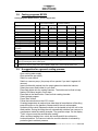
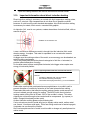
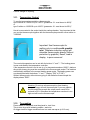
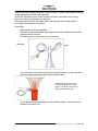
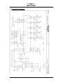
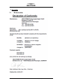
1
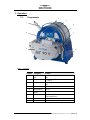
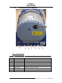
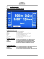
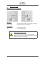
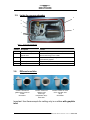
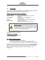
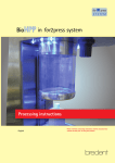
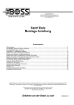
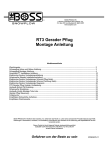
Instruction Manual for
Bench Top Casting Unit
MC20V
Contents
1.
Introduction........................................................................................................ 3
1.1. General description of the MC20V................................................................. 3
1.2. Machine components .................................................................................... 4
1.3. Technical Data .............................................................................................. 5
1.4. General information ....................................................................................... 6
2.
Putting into operation......................................................................................... 9
2.1. Set-up directions............................................................................................ 9
2.2. Mains supply ................................................................................................. 9
2.3. Cooling water ................................................................................................ 9
2.4. Protective Gas ............................................................................................. 10
2.5. Vacuum Pump............................................................................................. 10
3.
Operation......................................................................................................... 11
3.1. Components ................................................................................................ 11
3.2. Connections on the backside ...................................................................... 12
3.3. Operation elements ..................................................................................... 13
3.4. Operating buttons ........................................................................................ 17
3.5. Inside the vacuum chamber ........................................................................ 18
3.6. Different crucibles........................................................................................ 18
3.7. Test running ................................................................................................ 19
3.8. Casting programs MC20V ........................................................................... 20
3.9. A suggestion for a general casting process:................................................ 20
3.10.
Important information about direct induction heating................................ 21
3.11.
Temperature Control ................................................................................ 22
3.12.
Tree making ............................................................................................. 22
3.13.
To find out the weight of the metal .......................................................... 24
3.14.
About casting metal:................................................................................. 25
3.15.
Hints for castings in difficulty-to-cast metals............................................. 25
3.16.
Casting temperatures ............................................................................... 27
3.17.
Mixing instructions for flasks in Investing process .................................... 28
3.18.
Determining volumes of investment powder and water for Investment . 29
3.19.
Burnout cycles of flasks............................................................................ 30
3.20.
After casting: ............................................................................................ 33
4.
Service............................................................................................................. 34
4.1. Trouble shooting.......................................................................................... 34
4.2. Maintenance................................................................................................ 34
5.
Collection of Spoiled Castings ......................................................................... 35
6.
Connection diagram......................................................................................... 41
7.
Appendix.......................................................................................................... 42
7.1. CE-declaration............................................................................................. 42
7.2. Consumables .............................................................................................. 43
7.3. Error and Warning Codes............................................................................ 45
OPERATING_MANUAL_MC20V.DOC 18.03.11 KS
Seite 2
1. Introduction
1.1.
General description of the MC20V
The INDUTHERM mini casting machine MC20V is suitable to cast all kind of metals
into moulds or into investment flasks. Except dental alloys and very reactive alloys
like Magnesium. The melting charge is heated up by induction. The special
advantage of strong inductive heating is that the melting temperature is reached
rapidly, because the heat is directly generated in the metal or will transported to the
metal by a crucible with graphite insert. During the melting process, the metal is
thoroughly mixed by means of a magnetic field, ensuring a homogenous mixing even
when using mixtures of pure metals.
Crucibles with graphite inlet are used for metals up to 1300°C,
Ceramic crucibles for steel or Platinum up to 2000°C
Vacuum-Pressure mode in only one chamber
The casting mode is based on this new method: during the melting process the metal
and the flask are under full vacuum. The metal is poured into the flask by tilting the
whole chamber. Inside flask is also a vacuum which guarantees pouring without air
counter pressure. Now the vacuum will be replaced by gas overpressure rapidly: The
pressure impulse (inside of the flask is still under vacuum!) ensures excellent form
filling. The effect of vacuum in the flask and outside overpressure lasts for some
time, long enough until metal is already solid.
The most important fact of this system is quickly creating of vacuum and very fast
pressure built-up in the system. To the evacuate chamber it needs a strong vac
pump with 8 m³/h minimum, releasing vacuum + creating over pressure it needs a
gas bottle with PRESSURE regulator (NEVER a flow regulator !!!). Short connection
pipes make rapid pressure supply even better.
All functions are linked with the turning of the chamber: immediately after pouring
metal into the flask, over pressure comes automatically.
As mentioned before, a pressure impulse on top of liquid metal, while inside
there is still a vacuum, makes the good form-filling of this system. This means,
the flask by itself is a reservoir of the vacuum. As smaller the flask, as less
reservoir is there and pressure equalisation is quicker. In case of doubt (very
delicate items) or form filling problems take one size bigger for the flask than
necessary from aspect of dimensions
OPERATING_MANUAL_MC20V.DOC 18.03.11 KS
Seite 3
1.2.
Machine components
The machine consists of separate units built in a housing:
Inside the housing, the following components are installed:
-
microprocessor controlled induction generator DM-type
medium frequency transformer
oscillation circuit capacities
The front side:
-operating panel for control of melting cycles
The rear side
-on rear side, under a black plastic cover: interface RS232 for service
The casting chamber consists of:
-inductor, crucible, insulation parts, thermocouple
OPERATING_MANUAL_MC20V.DOC 18.03.11 KS
Seite 4
1.3.
Technical Data
MC20V
Crucible temperature
15 cm 3 (ceramic crucible)
10 cm³ (with grafite inlay)
max. 2000 °C
Melting performance
3.5 kW
Mains supply
230 V / 16 A, 50 or 60 Hz
Cooling water supply
2.5 - 5 bar / min. 1,5 ltr./minute
Cooling water recoil
Pressureless
Cooling water entry temperature
10 - 20 °C
Protective Gas
Argon oder Nitrogen, 8 bar
Vacuum
min. 8m³/h, 0,1 mbar abs.
Ambient temperature
10 - 35 °C
Relative atmospheric humidity
20 - 80 % Weight
Crucible volume
ca. 27 kg
Dimensions (width x depth x height)
400 x 400 x 450 mm
OPERATING_MANUAL_MC20V.DOC 18.03.11 KS
Seite 5
1.4.
General information
Safety information
In order to ensure a constant, ideal performance of the machine and to ensure safe
working conditions, the user is to observe the following safety measures:
The complete electrical wiring is to be performed only by qualified and specially
trained personnel.
Check the machine and the supply devices regularly on possible damages.
Keep your fingers away from moving parts
Before you use unknown material for your process, you must fulfil a risk analysis
If you use process material that develop toxic gases, the machine outlet "Gas
out" must not be release into the enviroment.
It is not allowed to melt flammable material or material which develops under
thermal influence gas, which creates an explosive atmosphere.
Before you melt material like used medical implants a risk analysis must be
performed. Additional the user must operate with personal safety equipment like
rubber gloves and face mask.
The cover of the inductor housing must be in horizontal possition all the time
The mains at the house must be easy accessible.
When opening cabinet/housings or when removing parts (exception: when this is
possible by hand), certain parts under electric power can cause danger. If
opening up the machine is necessary (before maintenance, change of machine
settings, repair or exchange of parts) the machine must be cut off the mains
voltage. If working on the opened machine is inevitable, only qualified trained
personnel aware of the danger caused hereby and aware of the relevant
regulations may be instructed to do this work.
Capacitors in the machine can still be charged even when the machine’s mains
supply is switched off.
When it seems that the machine can no longer be worked safely it has to be
taken out of production and secured against further unintentional use. The
following incidents indicate that safe working is no longer possible:
- the machine is visibly damaged
- the machine does not function
- uncommonly heavy wear from transportation
OPERATING_MANUAL_MC20V.DOC 18.03.11 KS
Seite 6
The safety valves placed inside the machine housing may not be removed,
closed or altered in any way.
As melted metal is processed with this machine (= temperatures up to 2000 °C),
the utmost care and attention has to be applied when working with the Machine.
The following necessary safety clothing is principally to be worn:
- fireproof clothes
- fireproof closed shoes
- fireproof gloves
- safety goggles
Special caution is essential when working with graphite crucibles and graphite
dies because these are only visibly hot at temperatures above 500°C!
In commercial enterprises the regulations for the prevention of accidents of the
relevant authority for electrical machinery are to be followed.
People with pacemakers must not be near the machine while it is running.
A trained responsible personnel is to supervise work with this machine.
Before you start using the machine, the manual of the MC20V must be read and
comprehended.
OPERATING_MANUAL_MC20V.DOC 18.03.11 KS
Seite 7
Use as determined/liability
This casting machine is designed and manufactured to comply with the latest
technical knowledge and according to approved safety regulations. When not putting
into operation correctly or not using the machine as determined, however, danger
and damages may occur. Therefore we suggest reading carefully and completely this
manual before putting the machine into operation and to follow the instructions given
there:
This machine is only to be used for melting, casting of precious metals normally
used for the production of jewellery.
This machine may only be connected as mentioned in this manual. The mains
supply as well as in- and outgoing pressures are to be provided as stated on the
machine label.
This machine was designed for use in closed spaces (indoors) and may only be
used for the above-mentioned purpose.
Only original INDUTHERM consumable and spare parts are to be used.
The machine may not be modified in any way. Technical changes may only be
effected with INDUTHERM GmbH’s prior written permission.
Damages caused by disregard or false interpretation of the contents of this
instruction manual result in an immediate expiration of the machine guarantee.
This instruction manual is conform to the latest technical condition of the machine
when printed. Technical changes and fittings subject to change.
INDUTHERM GmbH cannot and will not take responsibility for any damages
resulting of the above mentioned.
This instruction manual may not even partially be reproduced (photocopy, micro
film, computer processing etc.) without prior written permission of INDUTHERM
GmbH.
OPERATING_MANUAL_MC20V.DOC 18.03.11 KS
Seite 8
2. Putting into operation
On delivery, immediately check if the machine is complete and if there are any
transportation damages. In the case of damages, please contact at once supplier or
forwarding agent.
2.1.
Set-up directions
The machine should be placed on clean and dry ground. The ground should be even,
solid and level. The rear side of the machine must remain freely accessible to ensure
sufficient circulation of cooling air. The cooling air temperature must not exceed 35°C
and must not be contaminated. Only after all supply and connecting systems have
been connected, the machine may be put into operation.
2.2.
Mains supply
Only trained personnel may connect the machine. Please pay attention to the
nominal voltage and frequency stated on the machine label. The 1-phase current
may differ +/- 10% (maximum) from the nominal value. The mains supply must at
least be furnished with 20 A delay-action fuses (at 1* 230 V AC). The machine is
equipped with a 16 A- -connector when leaving INDUTHERM. All 3 lines (L1, N, PE)
must be connected correctly. Please take notice, that MC20V needs its own power
line from breaker. Do not connect other machines on this power line.
.
2.3.
Cooling water
Use two hoses with an outer ø of 6 mm for the cooling water. The water entry
pressure must be at least 2.5 bar and must not be more than 5 bar. The water
drainage must be without pressure. The water entry temperature must be above
10°C and must not exceed 25°C. The concentration of lime in the water must not be
more than 60 mg CaO/l. The cooling water must not be contaminated.
Caution: As long as the crucible temperature is above 100°C, the cooling water
supply must be open; otherwise the inductor insulation could be destroyed. In case
the cooling water supply stops while there is still a hot crucible inside the machine,
the crucible must be removed immediately.
OPERATING_MANUAL_MC20V.DOC 18.03.11 KS
Seite 9
2.4.
Protective Gas
The connection of inert gas supply is done by a hose with outside diameter 8 mm.
Primary pressure should be 6-8 bars. Regulator on the gas bottle is a pressure
regulator (NEVER use a flow regulator !!!) This armature must be purchased at a
serious dealer for gas bottles. Ask him! To purchase this armature at Indutherm:
difficulty because all countries have different standards in gas bottles.
If only platinum or other non-reactive metals has to be casted: it is in general possible
to use pressurized air.
For standard applications you can use nitrogen gas
For application in Pd 950-alloy it is a must to use good quality argon gas!
This gauge must show bar/PSI
but NOT Liters / Minute
2.5.
Vacuum Pump
The vacuum pump should be connected with the supplied tube with an outer
ø of 8 mm. Keep the vacuum tube as short as possible to avoid pressure loss.
Before starting unit: let vacuum pump run for 10-15 minutes to heat-up oil (Inlet
closed). Same after finishing casting: let it run for 10 minutes more (inlet closed).
This is specially important if vacuum pump is running also for Investment Unit!
Water steam/moisture makes a mixture with oil (emulsion) which makes the oil
disable.
OPERATING_MANUAL_MC20V.DOC 18.03.11 KS
Seite 10
3. Operation
3.1.
Components
4
5
1
6
7
2
3
Abb. 1:
8
front view
Position
1
2
3
Description
function
tilting handle with due to movement to the right the machine will
lock
cast
allows temperature measurements above
pyrometer
1300°C
inductor housing the melting and casting process takes place
here
4
LCD screen
see 3.3
5
control buttons
see 3.4
6
top plate with
handle
locks the inductor housin
7
lock
locks the system for safety reasons and to
allow overpressure
8
main switch
machine will be turned on and off here
OPERATING_MANUAL_MC20V.DOC 18.03.11 KS
Seite 11
3.2.
Connections on the backside
8
7
Abb. 2:
Position
6
5
4
3
2
1
Backside of machine
Description
function
1
label
label with serial number and technical data
2
air out
exit for overpressure
3
protective gas
input for protective gas
4
vacuum
connection for external vacuum pump
5
water in
input for cooling water
6
water out
output for cooling water
7
mains cable
electrical connection for machine
8
RS232 connection
connection for PC or modem for service
OPERATING_MANUAL_MC20V.DOC 18.03.11 KS
Seite 12
3.3.
Operation elements
MC20V screen when starting the machine
or "Temp. Edit"
On the middle section shown:
100°C
== actual temperature
1530°C
== set temperature
0.00 bar
== actual crucible pressure (-1 to 2 bars)
0.0 kW
== actual heating power in kW
3.5
== maximum heating power
13 Program
== active program with name "18ct yello"
Manual
== operation mode
On the left side shown:
Temp Temp +
Power Edit
== lower the set temperature even within a program
== rise the set temperature even within a program
== changes display to achieve temperature or power
controlling (will change to temperature controlling )
On the right side shown:
Program == go the the next program one place below (program 12)
Program +
== go the the next program one place higher
Program setup
== level to modify the selected program (here program 14)
OPERATING_MANUAL_MC20V.DOC 18.03.11 KS
Seite 13
MC20V modify program screen
On the top level shown:
0013 program
== selected program to modify
1530°C Temperature
== set temperature inside the crucible
115% Pyrometer correction
== allows you to adjust displayed temperature (if
necessary)
100% Heating power
== allows you to adjust displayed temperature (if
necessary)
0000 Washing before heating
== washing cycles before heating (starts with
vacuum, then backfill to 0.0 bar with protective gas).
Number display the cycles that will be done.
Recommend for Paladium alloys (very reactive
alloys)
0001 Washing while heating
== washing cycles during the machine heats
-0.90 bar Melting pressure
== melting pressure set value in bell
00.5sec Casting pressure start
== tilting angle to
2.00 bar casting pressure
== casting pressure set value
0030 s Vibration
== vibration time
OPERATING_MANUAL_MC20V.DOC 18.03.11 KS
Seite 14
On the left side shown:
Arrow up
Arrow down
== active parameter (highlighted with white background)
changes to the parameter one level above
== active parameter changes to the parameter one level
below ( here Pyrometer correction)
On the right side shown:
+
== changes set temperature to 1001
== changes set temperature to 0999
Main page
== display moves back
MC20V modify system parameter
If you start from the start page and you press“ Program setup“ for 5 seconds you get
access to the system paramter.
On the top level shown:
000:00015
== selected parameter == 000
value of parameter 00015: equals seven == pyrometer
If you press “Arrow up” you get access to the parameter 001 and higher.
By pressing “+” you change the value of parameter 000 to 1
OPERATING_MANUAL_MC20V.DOC 18.03.11 KS
Seite 15
MC20V modify program screen second page
If you press now „Service“ button you see the software ID, machine number and
generator number.
If you press now „Service“ button again you see the water flow and machine stat
OPERATING_MANUAL_MC20V.DOC 18.03.11 KS
Seite 16
3.4.
Operating buttons
MC20V buttons left and right side
Manual area:
Generator
Vacuum pump
== starts and stops heating ( if not operating in program )
== switches vacuum pump on and off
Automatic area:
Stop
Start
== stops active program
== starts selected program
Special function of "Start" button:
If you are operating within a program cycle and melting
pressure ist active, you can release and reactivate the melting
pressure by pressing the start button.
OPERATING_MANUAL_MC20V.DOC 18.03.11 KS
Seite 17
3.5. Inside the vacuum chamber
4
3
2
5
1
Abb. 3:
Position
shown with graphite inlet
Description
Function
1
thermoelement type N
allows a temperature measurement up to 1300°C
2
3
ceramic crucible with
graphite inlet
ceramic shield
in this crucible the graphite contains the heat and
transfers the energy to the metall
protects the thermocouple against contamination with
liquid metall or graphite
4
flask adapter
adapter for variuos flasks and mould sizes
5
flask
flask (here without investment)
3.6.
Different crucibles
Ceramic crucible with
grafite inlet for precious
metals
#12279021
Ceramic crucible for
Platinum And
others high
temperature alloys
#12279011
Ceramic crucible for CrNi,
CrCo und other steel
alloys
#12279020
Important: Use thermocouple for melting only in crucibles with graphite
inlet.
OPERATING_MANUAL_MC20V.DOC 18.03.11 KS
Seite 18
3.7.
Test running
After setting-up MC20V according to our instruction manual, you should
make a final countercheck before you start casting:
Please check once more connection:
Electrical Supply:
Cooling water:
Vacuum:
Protective Gas:
.
Voltage supply according to label on machine?
Plugged-in?
Water tap is connected to Water In?
Water tap open?
Vac-Pump installed, plugged-in and switched on?
Valve on bottle opened
Reduction Valve on bottles shows 6-8 bars?
After main switch on: If you start the first heating cycle, the
MC20V does a self-test. The routine is checking vacuum and
inert gas pressure. If vacuum is missing or system is leaking,
error message E081 appears. If inert gas pressure is missing
or too low, error message E083 appears.
Everything is OK? If not contact us!
Insertion of Crucible
Crucible has no damages or cracks?
Wool in glass shield?
Insertion of thermocouple
Thermocouple’s protection tube is mantled?
In crucibles with graphite inlet: Tip of thermocouple touches graphite?
If no thermocouple is used: do not forget to connect DUMMY-plug 13400022
Important: Use thermocouple for melting only in crucibles with graphite
inlet. Otherwise induction energy will stimulate thermocouple directly
(without protection by graphite). Result, read in display, is pure
nonsense!
OPERATING_MANUAL_MC20V.DOC 18.03.11 KS
Seite 19
3.8. Casting programs MC20V
Casting programs MC20V Version _02 since August 2011
Preprograms_MC20V_02
Graphite crucible with
thermocouple reading
Silver
Yellow
935/Cu
gold 18k
Material
Program
No.
Temperature*
°C
Pyrometer correction
%
Heating power
%
Washing before heating
Washing while heating
Melting pressure**
bar
Casting pressure start (in ° or °
seconds)
Casting pressure
bar
Vibration
sec
Label
*
**
***
Ceramic crucible with holder and
pyrometer reading
950Pt
CrCo
950Pd
stainl. steel
10
11
12
13
14
1000
0100
0050
0000
0000
-1.00
60°
1080
0100
0050
0000
0000
-1.00
60°
2000
0100
0100
0000
0000
-1.00
60°
2000
0115
0100
0000
0001
-0.90
60°
2000
0100
0100
0002
0000
-1.00
60°
2.00
0030
935/Ag
2.00
0030
750/YG
3.00
0030
950Pt
2.00
0030
CrCo
3.00
0030
950Pd
Temperature: Please see the alloys data sheet for recommended casting temperature.
Melting pressure: When the display shows “Melting”, the melting pressure can be applied at any
time by pressing the “Start” button again.
Casting should be as fast as possible. The temperature controlling takes too long. The casting
needs to be done by vision. Once the material is liquid wait 5-10 seconds and then cast!
3.9. A suggestion for a general casting process:
Open cooling water supply
Open protective gas supply
Switch on main switch
Switch on vacuum pump ( the pump will no operate if you start it against full
vacuum)
Insert crucible with material into the quartz glass tube inside the inductor.
Select the correct flask holder for your flask
Place flask holder into the casting chamber. The holder can be fixed to keep
flasks of 50-80mm length in 5mm steps.
Place flask in the flask holder. Close and lock casting chamber.
Select desired program.
Press "Start" button
Follow the instructions on the LCD screen
If casting temperature is reached (see data sheet of manufacturer of the alloy)
press the button on the handle to release and tilt the unit uninterrupted
clockwise till the catch. Release the button on the handle to lock the unit in the
tilted position. During the tilting the unit automatically switches from vacuum to
overpressure inside the casting chamber. The generator stops. On the display
"Time" a timer counts the seconds after casting.
After a sufficient waiting time, unlock the handle and tilt the unit back to
horizontal position. The vacuum inside the crucible chamber is released by
protective gas to ambient pressure.
OPERATING_MANUAL_MC20V.DOC 18.03.11 KS
Seite 20
Open the casting chamber and remove the flask and the flask holder.
3.10. Important information about direct induction heating
Direct induction melting is necessary on metals with high temperature melting points,
such as Pt, steel etc. High temperatures do not allow use of graphite crucibles
because of quick burning under standard atmosphere. Also direct induction melting
is necessary on metals, which reacts unwanted with graphite.
An Induction Coil, used in our systems, creates streamlines of electrical field, with an
specific direction.
Fieldlines on an induction coil
If now a conductive material like metal is brought into this induction field, metal
absorbs energy, it couples. This metal is separated in an unconductive ceramic
crucible in between.
As bigger now the working surface of the metal, as more energy can be absorbed, as
quicker melting can happen.
This is why metal parts should be placed rectangular to field line = horizontal, to
provide optimal absorption of energy.
So it makes sense to place metal plates horizontal, also bigger wires couple more
energy in horizontal position.
This is a typical application what does not work with a MC15.
Here are 20g of small thin Platinum sheets.
Miscues:
- 20 grams of Platinum melt only as one piece
- the material is standing vertical (IIII).
Much better would lying horizontal (==) to cross fieldlines!
Please take care that this metal parts have enough distance to crucible’s wall to
prevent disruption of crucible by extension of the metal pieces before melting.
Please also take notice, that induction melting systems need a certain amount of
volume to absorb enough energy for melting. The MC20V with direct induction
heating needs a filling level of at least 20% of the crucible’s volume. Thin wires,
chipping do not have enough volume and should be compressed (by a press) or
better, charged into already molten metal.
At direct induction melting please notice following hint:
If a too voluminous piece of metal will given to already molten metal, molten metal
can „freeze“, it becomes solid again. If this form-fitting metal now is heated-up again,
it expands can can disrupt the crucible.
Hint: load complete amount of metal in cold crucible or charge only small pieces into
molten metal
OPERATING_MANUAL_MC20V.DOC 18.03.11 KS
Seite 21
Caution: danger of squirting.
3.11. Temperature Control
To use the temperature controller a thermocouple
type N article no 13400010 up to 1300°C (parameter -01- must be set to 0002) *
or
type S article no 13000030 up to 1600°C (parameter -01- must be set to 0001) *
Has to be connected to the socket inside the casting chamber. Very important is that
you use the thermocouple together with the thermocouple protection cover article no
13200045.
Important: Use thermocouple for
melting only in crucibles with graphite
inlet. Otherwise induction energy will
stimulate thermocouple directly (without
protection by graphite). Result, read in
display, is pure nonsense!
The nominal temperature can be set with the buttons "+" and "-". The heating power
is now controlled by the temperature controller.
If the temperature control is not in use (e.g. for temperatures above 1600°C, platinum
alloys) the dummy plug must be connected to the thermocouple socket. The machine
automatically switches to the manual heating power mode. The heating power can
now be adjusted with the buttons "+" and "-" (display "P00" to "P100").
Without thermocouple, without dummy plug or with defective thermocouple the
display shows "E041".
Attention: Do not use a thermocouple in direct heating
process! Energy will melt thermocouple! If you use graphite
crucible and thermocouple the output power needs to be
reduced to 50%. Otherwise the temperature overshoot is too
high and will burn the thermocouple.
3.12. Tree making
Pieces made of wax/plastic must be placed in „tree“ form.
This is done by a small soldering needle + wax wire.
On bigger trees for bigger machines there is a main wax sprue (ø 8-10 mm).
OPERATING_MANUAL_MC20V.DOC 18.03.11 KS
Seite 22
On this main sprue single pieces are fixed in a style of a spiral. This is best for cutting
off the casting pieces after casting process.
On MC20V this tree is more a bush, pieces are fixed on the button cone directly.
Only a short piece of main sprue is required.
This main sprue is fixed in the rubber base, the diameter of the rubber base is
according to the diameter of the flask.
Some hints:
Make sprues as short as possible
Diameter of sprues should be big enough to guarantee optimal feeding of the
castings with liquid metal.
Place wax pieces so that wax can flow out easily
Not good
good
The connection of the waxes to the sprue should be done in a hydro-dynamic
style, to prevent turbulences while pouring liquid metal.
Liquid metal is heavy in weight, it
can break away thin parts of the
gypsum. Create all connections in
hydro-dynamic proper style.
Do not place waxes/plastic parts to close to flask cylinder. There should be a
distance of at least 5 mm
OPERATING_MANUAL_MC20V.DOC 18.03.11 KS
Seite 23
3.13. To find out the weight of the metal
ALL rubber bases must be determined on a scale. Write exact weight on this rubber
bases by a felt pen.
After mounting the tree, take the total weight. Deduct the rubber base weight from the
total weight = net wax weight. To simplify matters we assume the specific weight of
wax as 1.
Metal weight is calculated by multiplying wax weight by the specific weight of the
metal:
Metal
Water, wax
Aluminium
Steel
Brass
Bronze
Silver
Nickel silver
Gold 333
Gold 585
Gold 750
Gold 900
Palladium 950
Platinum 950
Spec. weight g/cm³
1,00
2,70
8,50
8,40
8,80
10,50
8,40
10,50
13,70
15,20
17,40
12,00
20,70
Example:
Complete weight (wax + rubber base) 43,5g less weight of rubber base 38g = 5,5 g
wax
5,5 g wax means
Metal
Silber
Gold 750
Wax weight x Specific weight
5,5 g x 10,5
5,5 x 15,20
Metal weight
57,75 g
83,60
After the calculation: Place flask cylinder and fix it carefully on the rubber
base. Do not touch wax pieces.
OPERATING_MANUAL_MC20V.DOC 18.03.11 KS
Seite 24
3.14. About casting metal:
Because of high costs casters do not like to use every time fresh alloy. For some
alloys customers mix „second hand metal“ up to 50%, mainly Au, Ag based alloys.
Never use finished jewellery pieces. The alloy composition is not known,
solder in casting material will give no good casting result.
Never mix two alloys, even if they have the same contents of gold
All already cast metal should be very clean, sand blasting and pickling are
adequate methods. Caution: rest of glass beads, investment material or rests
of acid are unwanted. Clean in ultrasonic in distilled water.
Alloys with zinc content: give much more fresh metal to „old“ metal.
Alloys with high carat (Pt 950, Au 21/22/24 ct) can be re-used to 100%
Pd 950 is a very reactive metal. No chance to melt it twice. Use fresh metal!
Prevent oxidation by melting under vacuum and inert gas only.
Never use boric acid for melting!
3.15. Hints for castings in difficulty-to-cast metals
Brass, gold 8/9/10 ct, some alloys gold
14ct
These alloys have a high content of zinc.
Some of the zinc evaporates during the
heating phase. If vacuum is used in the
melting chamber, much more zinc would
evaporate. To prevent this problem there
is a small trick:
Put the metal in the cold crucible, set in
flask at the same time. Push button start
(heating) and start (vacuum) again
immediately. Now a vacuum is built up,
but the metal, still not liquid, cannot
evaporate zinc. After reaching full
vacuum, push another time start
(vacuum will be released by gas). After
reaching casting temperature, cast
immediately.
OPERATING_MANUAL_MC20V.DOC 18.03.11 KS
Seite 25
Palladium 950
Platinum
Palladium should be melted in the same
type of crucible like Platinum. Palladium
has a strong reaction with oxygen. That´s
why we recommend to „wash“ the
chamber atmosphere as follows: Set
„power“ to zero “P000”. Put in metal, set
in flask.
Push button start (want to heat, but set
point power is zero = no heating
possible). After then start again =
vacuum comes. After reaching vacuum,
another push on start: vacuum will be
released by ARGON gas. Make only
ONE washing cycle!
Change setting of power to power
P100(%). Wait until metal is molten
completely and cast immediately.
IMPORTANT: Use Argon gas for
palladium castings.
Set heating power to P100 (100%).
Use the special ceramic crucible for
Platinium. Put metal into the (cold)
crucible. Push “Start” once for heating,
set in flask and lock chamber. Push
“Start” second time to start the vacuum.
Full vacuum is reached inside the
gypsum in around 30 seconds (see
timer) After metal is molten totally, wait
for max. 8 seconds and cast. This will
prolongate the life time of the crucible!
Adjust your process in that way, that at
the moment for poring out the Pt and the
end of evacuation time (at least 30
seconds) of the flask are concurrently.
Important hint:
Pt, molten in a standard Pt-crucible, is
absorbing silicate out of the crucible
material. As more often you re-melt
same batch of metal, as more silicate
will be absorbed. This makes Pt brittle.
Help: Coating of the inside of the crucible
by use of liquid zircon oxide !
After casting: leave flask under set
parameters for approx. 240 seconds.
OPERATING_MANUAL_MC20V.DOC 18.03.11 KS
Seite 26
Cobalt-chromium,
steel alloys
Set heating power to P080 (80%).
Use the ceramic crucible for steel.
Put in crucible, set in flask. Push “Start”
twice to start heating and vacuum. If full
vacuum is there for at least 30 seconds
(see timer) increase heating power to
P100 (100%) and cast when metal is
ready.
One more problem of NiCr, CoCr and
steel alloys: some alloys tend to splash
in molten condition and under vacuum. In
this case it is useful to change setting of
parameter P060 = limitation of vacuum.
For standard application set of -21- is O.
Setting of -21- into 1 means max.
vacuum is –0.90bar,
P060 into 2 means max. vacuum is 0.80bar. Please change back after
casting to standard set!
3.16. Casting temperatures
The casting temperature depends on metal alloy and style of castings:
High melting point of metal needs high flask temperatures, thin and delicate pieces
with long flow ways too.
Low melting point of metal needs lower flask temperatures, heavier massive pieces
too.
Ask metal supplier about their recommendation.
List of Recommended Flask Temperatures
Metal
Aluminium
Silver 925
Y. gold 14 ct
Y. gold 18 ct
W. gold 18 ct
W.gold 18 ct Pd
Steel
Palladium
Platinum
Melting point
720°C
980°C
950°C
1050°C
1150°C
1300°C
Flask temperature in °C
Pieces
Pieces
Pieces
thin
medium
heavy
300
250
200
650
600
400-600
620
600
400-600
620
600
400-600
620
600
400-600
650
630
400-600
900
800
700
950
900
870
950
900
850
OPERATING_MANUAL_MC20V.DOC 18.03.11 KS
Seite 27
3.17. Mixing instructions for flasks in Investing process
Investment process means, that powder is mixed for a certain time with water in a
special ratio into a slurry and filled into a flask.
It is generally possible to do it by hand in an open rubber bowl. But during this
process you will mix in air which creates bubbles afterwards in the investment and on
top of the castings as well. Vacuum is required!
After mixing by hand you can put the investment slurry into a vacuum for a short
while to suck out air bubbles. After then fill slurry into a flask and place the filled flask
into vacuum again, if possible on a vibrator.
But this is a not really good way to make a proper investment:
To mix air into slurry and suck it out after by vacuum is making no sense:
prevent investment slurry against mixing in air = do whole mixing process
under vacuum.
Ratio of water/powder is given in instruction manual. Whenever slurry comes
under vacuum, the boiling point of water comes down from 100°C to room
temperature! Water steam comes out (you can see the bubbles in the slurry)
and the ratio of the water: powder mixture changes.
Mixing slurry, a working time is given for mixing and filling of flask. After then
slurry has to get a rest to become solid without moving or vibration in a quiet
place. If processing time takes too long, slurry already starts becoming solid
during this phase. This will cause problems.
The target is to mix slurry under vacuum, to fill slurry under vacuum into the flask
under vibration and to release vacuum as soon slurry is in the flask. This is only
possible in a system called investment mixing apparatus.
After filling the flask: give slurry 1 hour time to become totally solid. No moving of the
flask, place in on a quiet place without vibration.
Afterwards: remove rubber base.
Investment mixer for MC20V
OPERATING_MANUAL_MC20V.DOC 18.03.11 KS
Seite 28
3.18. Determining volumes of investment powder and water for
Investment
determining amount of powder per flask this formula is helpful:
Volume of flask in ccm x 1,4 = amount of powder in grams
For example flask ø 8 x 8 cm
r² x x h x 1,6 = amount of investment powder in g
4² x 3,14 x 8 x 1,4 = 570 g
Or on flasks ø 5 x 5,5 cm
2,5² x x 5,5 x 1,4 = 150 g
This is gross weight, volume of cone and wax pieces must be subtracted!
To find out proper the amount of water according to the instruction manual of
investment material:
Ratio, given by instructions: 100:40
100:40 = 570:x
40 x 643:100 = x = 228 g water
Please take notice:
More water makes investment material more permeable for gases = better form
filling. If the manufacturer gives a mixing ratio 37 .. 39 : 100, use for filigree items
39:100, on standard items use 37:100!
Make very precise measurement, use water with exact 20°C Too cold or too warm
water can strongly change properties of the investment material like mixing time etc.
Short cut:
For standard MC20V flasks there are some recommendations:
gypsum bonded investment powder like Goldstar XL, XXX, Kerr Satin Cast 20 etc.
100 : 40 powder : water
flask size
investment powder
in grams
water in ml
mixing time in
min:sec
Ø 30mm x 55 mm
Ø 50mm x 55 mm
Ø 65mm x 55 mm
Ø 80mm x 55 mm
Ø 50mm x 80 mm
Ø 65mm x 80 mm
Ø 80mm x 80 mm
60
150
270
390
220
370
560
24
60
108
156
88
148
224
4:00
4:00
4:00
4:00
4:00
4:00
4:00
phosphate bonded investment powder like Goldstar Platincast, H.T.
100:35
OPERATING_MANUAL_MC20V.DOC 18.03.11 KS
Seite 29
flask size
investment powder
in grams
water in ml
mixing time in
min:sec
Ø 30mm x 55 mm
Ø 50mm x 55 mm
Ø 65mm x 55 mm
Ø 80mm x 55 mm
Ø 50mm x 80 mm
Ø 65mm x 80 mm
Ø 80mm x 80 mm
60
150
270
390
220
370
560
21
52
95
136
77
130
196
3:00
3:00
3:00
3:00
3:00
3:00
3:00
3.19. Burnout cycles of flasks
After investment process the flasks have to undergo a firing process. For this
purpose the flasks have to be placed in the furnace with the button (opening) down to
ensure a complete flow-out of wax.
The firing cycle of gypsum bonded flasks has normally 3 phases:
Phase 1. Melting out of wax and steaming out remaining moisture of flasks
very slowly. This steaming out process should be done very gently to prevent
gypsum against cracks. In case of the flasks for MC20V (comparatively small)
we recommend to reach a temperature of 300°C (= ramp of 2,5°C/min) in 120
minutes. On bigger flasks we recommend to go to 150°C - 180°C in 120
minutes.
Investment powder is a good insulator, that’s why the heat takes time to reach
the core of the flask. To ensure that the flasks heat up homogeneous, let the
flasks have a rest at the hold temperature of 30 minutes on small flasks and
up for 60 minutes on bigger flasks.
Phase 2 burning process of flasks. This process is similar to a sintering
process: single particles bake together (bonding) and the investment material
becomes much stronger. Gypsum bonded investment materials need 730°C
for this bonding process. To reach this temperature starting at 300°C, ramp
should be 4°C/min = process takes around 2 hours. On bigger flasks (starting
at 150°C, we recommend to select ramp 5°C/min. Duration in the furnace: for
small flasks like MC20V around 1 hour, on bigger flasks up to 5 hours.
Phase 3 Bringing flasks to casting temperature. After reaching the casting
temperature in the furnace, please give flask a rest of 30 – 60 minutes
(depending on size) to ensure that set the temperature is also inside flask.
For phosphate bonded investment material you can go, after phase nos. 2,
directly to the final casting temperature for example 900°C. Give flask a rest at
this temperature of 30-60 minutes at least, depending on the size of the flask.
OPERATING_MANUAL_MC20V.DOC 18.03.11 KS
Seite 30
Temp.
730
Casting temperature
300
2
3
5
6
time
in h
Firing cycle for MC20V, gypsum bound
investment material
This „gentle“ firing cycle needs around 7 hours, so from wax to casting it will take only
one day. But it is also possible to push this cycle. Here a recommendation of a
RAPID firing cycle:
OPERATING_MANUAL_MC20V.DOC 18.03.11 KS
Seite 31
Temp.
730
Casting temperature
300
0,5
1
1,5
2
3
time
in h
RAPID firing cycle for flasks MC20
gypsum bonded investment material
Caution: In case of a „gentle“ firing cycle all amenities of the investment material are
prevented from damage. A rapid firing cycle doesn’t take care on this amenities.
Already aged investment powder or thus of lower quality can react because of gruff
handling with cracks.
In the dental field most people are using „SPEED“ investment material. The fresh
invested flask can be set into the HOT furnace directly. After 1 hour the flask is ready
for casting. Please ask a Dental Depot about this investment material.
OPERATING_MANUAL_MC20V.DOC 18.03.11 KS
Seite 32
3.20. After casting:
Most castings in gold- and silver alloys, palladium- and platinum alloys can be
quenched immediately after the 240 seconds cooling time in the machine.
Except: stone in place castings, they should cool down to room temperature.
However, some alloys need to cool for prolonged time, see datasheets of alloy suppliers.
Castings in CoCr, NiCr and steel alloys should cool down to room temperature before
removal of the flask.
For flasks with gypsum bounded Investment material:
Leave the flask 240 seconds after casting under over pressure. In this time you can
be sure that even inside of the casting metal is solid. After this 240 seconds: Quench
flask in water soon.
Caution:
For a stone-in-place-casting process: let cool down flask to room temperature!
Otherwise stones will crack!
For phosphate bonded investment material:
Wait until flask has reached room temperature. Break investment by a hammer or so.
Cleaning the tree
For removal of the remaining plaster and oxidation skin, a sand blasting cabinet is
very useful. Use of acid is dangerous and banned in most countries by government's
law.
Gypsum bonded investment: use of glass beads is good enough
For phosphate bonded investment: it is better to use corundum.
OPERATING_MANUAL_MC20V.DOC 18.03.11 KS
Seite 33
4. Service
4.1.
Trouble shooting
MC20V does not start: Is the plug plug in? Fuse of the electrical circuit tripped?
Otherwise MC20V will show information by an error code system in the display: Exxx
There are two graduations:
Warnings: will be displayed if something is wrong, but machine will not shut down.
Errors: will shut down machine immediately to prevent system against serious
damages.
This warnings/errors are in a special list included in a list attached to generator
documentation in the instruction manual. If an error message is not included this list
please contact us.
Attention: On our webside
http://www.indutherm.de/errors.html
you can find examples how to troubleshoot problems
If you contact INDUTHERM or your dealer always provide
serial no. or service no. of machine = This is necessary for us
to give assistance
4.2.
Maintenance
A routine check/regular cleaning of the following is necessary.
Caution: disconnect the machine first!
Daily (before casting):
Remove crucible and quartz glass tube, carefully clean inductor housing.
Before reinstalling the above parts, check those and replace if necessary.
Annually:
Depending on the water quality, the cooling system should be cleaned with 25% citric
acid. The cooling system should be treated with this acid for approx. 1 hour. Then
clean the system thoroughly with pure water and check on eventual leakages.
OPERATING_MANUAL_MC20V.DOC 18.03.11 KS
Seite 34
5. Collection of Spoiled Castings
Horizontal Flashing or Finning
Cause
Incorrect powder / water ratio (too much
water).
Work time of investment not used up.
Remedy
Using correct amount of water
(especially important with vacuum
investing machines).
Ensuring the work time is used up and
slurry temperature is 20 - 22ºC
Other Flashing Or Finning
Cause
Work cycle too long. Investment
beginning to set while still under vacuum.
Disturbing the flasks too soon
Heating too quickly during de-wax.
Moulds allowed to dry out before burn
out.
Remedy
Ensuring the work cycle is not too long
and slurry temperature is 20 - 22ºC.
Leave the flasks for at least one hour.
Do not exceed 150ºC during de-waxing.
If not burning out the same day, keep
moulds wet by covering with wet sacking
or plastic sheets.
OPERATING_MANUAL_MC20V.DOC 18.03.11 KS
Seite 35
Bubbles - Complete Spheres
Cause
Investment too thick. Too little water.
Vacuum pump/ tank faulty.
Work cycle too long. Investment
beginning to set while still under vacuum.
Remedy
Use correct powder / water ratio.
Ensure equipment is regularly serviced
and adequate for the task.
Ensuring the work cycle is not too long
and slurry temperature is 20 - 22ºC.
Bubbles-Incomplete Spheres
Cause
Static electricity on waxes.
Grease or dirt on waxes.
Remedy
Use a wax wash. NOTE: THE WAX MUST
BE COMPLETELY DRY BEFORE
INVESTING.
OPERATING_MANUAL_MC20V.DOC 18.03.11 KS
Seite 36
Water marking
Cause
Incorrect powder / water ratio (too much
water).
Work time of investment not used up.
Remedy
Using correct amount of water.
(Especially important with vacuum
investing machines).
Ensuring the work time is used up and
slurry temperature is 20 - 22ºC.
Gas porosity
Cause
Overheating the metal.
Inadequate burn out.
Flask overheated during burn out.
Impurities in the metal.
Remedy
Reduce metal casting temperature.
Increase the time at 730ºC.
Ensure maximum burn out temperature
does not exceed 730ºC.
Do not use more than 50% recycled alloy
and ensure it is clean
OPERATING_MANUAL_MC20V.DOC 18.03.11 KS
Seite 37
Rough Surfaces
Cause
Rough waxes.
De-wax temperature too hot.
Steam de-waxed for too long.
De-waxed too quickly.
Flasks overheated during burn out.
Metal too hot.
Remedy
Use less release agent on the rubbers.
Can be caused by excess talc.
Do not exceed 150ºC during de-wax.
Steam, de-wax for a maximum of 1 hour.
Steam will erode surface of the
investment.
Leave flask for at least 1 hour to achieve
maximum strength before de-waxing
Ensure maximum burn out temperature
does not exceed 730ºC.
Reduce casting temperature.
Inclusions
Cause
Improper sprues.
Crucible break down.
Dirty metal.
Flasks overheated during burn out.
Remedy
Eliminate sharp corners in sprue system.
Replace crucible. Do not used old,
disintegrating crucibles.
Do not use more than 50% recycled alloy
and ensure it is clean
Ensure maximum burn out temperature
does not exceed 730ºC.
OPERATING_MANUAL_MC20V.DOC 18.03.11 KS
Seite 38
Incomplete castings
Cause
Metal or flask too cold.
Improperly sprued.
Incomplete burn out.
Remedy
Increase casting temperatures. If the
metal or mould is too cold, the metal will
freeze before completely filling the
mould.
The sprue system should be designed to
allow the metal to enter easily and
without restriction.
Increase the burn out time at 730ºC. If
the flask is not properly burnt out it will
be impermeable and not allow gases to
escape when the metal enters the mould.
Shrinkage porosity
Cause
Incorrect sprue
Flask temperature too low and sprue is
incorrect.
Remedy
Sprues should be attached to the
heaviest piece of the casting. There
should be sufficient sprues to ensure the
casting is adequately fed.
The flask temperature should be just hot
enough to achieve complete fill,
according to the mass of casting
OPERATING_MANUAL_MC20V.DOC 18.03.11 KS
Seite 39
Blisters, Spalling
Cause
Flask being heated too rapidly during
de-wax.
Flasks overheated during burn out.
Flasks put in furnace too soon after
investing
Remedy
Do not exceed 150ºC during de-wax.
Wax will boil and erode investment
surface.
Ensure maximum burn out
temperature does not exceed 730ºC.
Leave flasks undisturbed for a
minimum of one hour before de-wax.
OPERATING_MANUAL_MC20V.DOC 18.03.11 KS
Seite 40
6. Connection diagram
OPERATING_MANUAL_MC20V.DOC 18.03.11 KS
Seite 41
7. Appendix
7.1.
CE-declaration
OPERATING_MANUAL_MC20V.DOC 18.03.11 KS
Seite 42
7.2.
Consumables
The spare part list for this machine starts on next page.
INDUTHERM is now using only machine specific spare parts lists, which contain all
the information for your machine.
The list is printed on the following pages.
The name of the stored list starts with a
1.)
G
2.)
The next 5 digits are the machine number.
3.)
Next is the specification for what application it is used for. (only at
multipurpose machines)
4.)
The version index. A new machine has the index _00.
One example is G10120_ 00. This is the list of the machine serial no 10120 and the
spare parts shown are for vacuum casting, index 00.
We are pleased to send you this data on request as a PDF file G10120_ 00.pdf. This
makes it easy for you to order the correct spare parts. If the list changes and the
index get one step higher to _01 please save the old file _00 into a section “old” or
delete it.
If spare parts are replaced by new parts, the index will be incremented. This ensures
that you always receive the latest version of consumables and spares. To be sure
that the data is correct, INDUTHERM and their sales partners or end customers must
work together.
Besides of the standard spare parts we have additional files to support you
accesory_parts_MC20V.pdf
you can select flask adapters
and ingots
optional_spare_parts_MC20V.pdf
shows consumables for different
materials
replacement_parts_MC20V.pdf
the replacement parts of the
machine
Original INDUTHERM parts are clearly marked with our 3D hologram.
For other spare or replacement parts please contact our sales partner for your
country or our order department at the telephone no.:
+49-7203-9218-40.
OPERATING_MANUAL_MC20V.DOC 18.03.11 KS
Seite 43
Bitte anstelle dieser Seite die aktuelle Verbrauchsteileliste
und die Bilderliste der Verbrauchsteile
einfügen !
/ Replace this side with actual spare parts list G xxxxx = Serial
number of machine
OPERATING_MANUAL_MC20V.DOC 18.03.11 KS
Seite 44
7.3.
Error and Warning Codes
The Error and Warning Codes for this machine start at next page.
Attention: On our webside
http://www.indutherm.de/errors.html
you can find examples how to troubleshoot errors.
Here you find PDF files with examples and pictures
Attention: Warnings will not shut down machine! You
can still operate machine, but inform us please.
The software documentation for this DM - generator system has 7 digits and starts
with 8000xxx.
xxx = is the software index.
Complete name "software_documentation_80000xx_customer.PDF"
OPERATING_MANUAL_MC20V.DOC 18.03.11 KS
Seite 45
History nicht mit Ausdrucken in PDF Somit nur
Seite 1-45 drucken
Date
01.09.11
User
KS
History
Kopiert aus MC15+ Stand Aug 2011