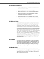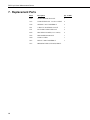
1
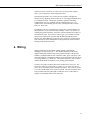
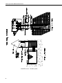
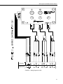
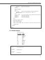
DB1 Liquid Level
Measurement Sensor
Revision: 12/07
C o p y r i g h t © 1 9 9 3 - 2 0 0 7
C a m p b e l l S c i e n t i f i c , I n c .
Warranty and Assistance
The DB1 LIQUID LEVEL MEASUREMENT SENSOR is warranted by
CAMPBELL SCIENTIFIC, INC. to be free from defects in materials and
workmanship under normal use and service for twelve (12) months from date
of shipment unless specified otherwise. Batteries have no warranty.
CAMPBELL SCIENTIFIC, INC.'s obligation under this warranty is limited to
repairing or replacing (at CAMPBELL SCIENTIFIC, INC.'s option) defective
products. The customer shall assume all costs of removing, reinstalling, and
shipping defective products to CAMPBELL SCIENTIFIC, INC. CAMPBELL
SCIENTIFIC, INC. will return such products by surface carrier prepaid. This
warranty shall not apply to any CAMPBELL SCIENTIFIC, INC. products
which have been subjected to modification, misuse, neglect, accidents of
nature, or shipping damage. This warranty is in lieu of all other warranties,
expressed or implied, including warranties of merchantability or fitness for a
particular purpose. CAMPBELL SCIENTIFIC, INC. is not liable for special,
indirect, incidental, or consequential damages.
Products may not be returned without prior authorization. The following
contact information is for US and International customers residing in countries
served by Campbell Scientific, Inc. directly. Affiliate companies handle
repairs for customers within their territories. Please visit
www.campbellsci.com to determine which Campbell Scientific company
serves your country. To obtain a Returned Materials Authorization (RMA),
contact CAMPBELL SCIENTIFIC, INC., phone (435) 753-2342. After an
applications engineer determines the nature of the problem, an RMA number
will be issued. Please write this number clearly on the outside of the shipping
container. CAMPBELL SCIENTIFIC's shipping address is:
CAMPBELL SCIENTIFIC, INC.
RMA#_____
815 West 1800 North
Logan, Utah 84321-1784
CAMPBELL SCIENTIFIC, INC. does not accept collect calls.
DB1 Table of Contents
PDF viewers note: These page numbers refer to the printed version of this document. Use
the Adobe Acrobat® bookmarks tab for links to specific sections.
1. Overview.......................................................................1
2. Specifications ..............................................................2
3. Installation....................................................................2
4. Wiring............................................................................3
5. Programming ...............................................................6
5.1 CR1000 Example......................................................................................6
5.2 CR10(X) Example ....................................................................................7
6. Maintenance ...............................................................10
6.1
6.2
6.3
6.4
Periodic Maintenance .............................................................................11
Solenoid Valve .......................................................................................11
Fittings ....................................................................................................11
Needle Valve ..........................................................................................11
7. Replacement Parts ....................................................12
Figures
1 and 2. The DB1 System ...............................................................................4
3. Wiring Diagram for DB1............................................................................5
This is a blank page.
i
This is a blank page.
DB1 Liquid Level Measurement Sensor
1. Overview
The double bubbler is a self-calibrating system for liquid level measurement.
This manual focuses on water level measurement in stilling wells or open
channels, but the information applies to other liquids as well. The system
detects water level by measuring the pressure required to force a nitrogen gas
bubble from a submerged tube. The nitrogen pressure in the tube is equal to
the hydrostatic pressure created by the exiting bubble. Before each stage
measurement, the pressure transducer is calibrated by measuring the
hydrostatic pressure difference between two tubes installed a fixed vertical
distance apart in the liquid to be measured. These values are used to calculate
the multiplier value for the liquid level measurement. This self-calibration
minimizes the effects of temperature and long-term drift on the pressure
transducer, allowing a single pressure transducer to achieve a much higher
measurement accuracy (±.05%). The self-calibration theory is discussed in
detail by Dedrick and Clemmens (1984, 1986).
A single pressure transducer is used to measure three pressure lines (h1, h2, or
offset). The line to be measured is controlled by the three 2-way solenoid
valves on the manifold. The "bubble rate" is controlled by the two needle
valves on the manifold assembly labeled #1 and #2. The needle valve labeled
#1 controls the bubble rate for the pressure line used to measure h1. The
needle valve labeled #2 controls the bubble rate for pressure line #2 used to
measure h2. The needle valve is turned clockwise to decrease and counterclockwise to increase the bubble rate. The suggested bubble rate is 1 to 3
bubbles/sec. The third solenoid valve is used to measure atmospheric pressure,
which will be used as the offset value.
The manifold assembly requires considerably more power compared to a
normal sensor. For this reason, an SP10 10-watt solar panel or AC power in
conjunction with a sealed rechargeable battery is recommended for the DB1
system.
References
Dedrick, A.R. and A.J. Clemmens, Double-bubblers coupled with pressure
transducers for water level sensing, Transactions of the ASAE, Vol. 27, No. 3,
pp. 779-783, 1984.
Dedrick, A.R. and A.J. Clemmens, Instrumentation for monitoring water
levels, Proc. of Agri- Mation Conference and Exposition, ASAE, March 3-5,
Chicago, IL, pp. 148-152, 1986.
1
DB1 Liquid Level Measurement Sensor
2. Specifications
Measurement Range:
Option - 5
Option - 15
Option - 30
(0 to 5 psi/0 to 11.5 ft.)
(0 to 15 psi/0 to 34.5 ft.)
(0 to 30 psi/0 to 69 ft.)
Maximum Overpressure Range:
Option - 5
Option - 10
Option - 15
20 psi
45 psi
60 psi
Transducer Accuracy:
± 0.05 % Full Scale
Temperature Range:
-25° to + 50°C
Supply Voltage:
12 Vdc
System Current Drain:
75 mA (Activated)
0.5 mA (Quiescent)
Valve Current Drain:
40 mA (Activated)
0 mA (Deactivated)
Maximum System Pressure:
100 psi
3. Installation
Mount the DB1 liquid level assembly to the enclosure back-plate using the
supplied plastic screw grommets and Phillips screws. Using the supplied
tubing cutter, cut sections of tubing for the nitrogen, h1, h2, and offset pressure
lines. Insert the h1 pressure line into the elbow fitting below the valve marked
#1. The line is installed correctly when it does not release without pressing the
red fitting into the valve assembly. Insert the h2 pressure line into the elbow
fitting below the valve marked #2. Insert the offset line into the elbow fitting
to the right of the valve marked #2. Insert the nitrogen supply line into the
elbow fitting on the right side of the manifold assembly.
Permanently install h1 and h2 a fixed vertical distance apart in the water (see
Figure 2, delta h). Maximize the fixed distance between h1 and h2, while
keeping h1 at least six inches below the surface of the lowest anticipated water
level. If the water level drops below h1 you will get irregular data readings.
The accuracy of the water level measurement is affected by the exactness of
the delta h measurement. To increase measurement accuracy, cut the end of
the submerged tubing at a 60 degree angle to decrease the gas bubble
deformation as it exits the tube.
The DB1 Liquid Level System requires a compressed gas supply. The most
common gas is a 225 ft3 nitrogen bottle with an appropriate "automatic
pressure relieved" pressure regulator. The pressure range set on the regulator
depends on the water level to be recorded. For example, if the DB1 system is
installed in a stilling well to measure stream level, and the stream level
2
DB1 Liquid Level Measurement Sensor
fluctuates between 5 and 15 ft (2.2 and 6.5 psi), set the pressure regulator
above 7 psi (read 10 psi) to ensure adequate pressure.
Open the nitrogen bottle valve, set the pressure regulator, and adjust the
nitrogen flow by adjusting the two needle valves. The suggested bubble rate is
1 to 3 bubbles/seconds. The nitrogen gas bottle, regulator, and tubing
(Campbell P/N 7567) are available from any welding supply store. Use
common sense when installing pressure lines, checking for leaks, moisture,
kinks, etc. in the lines.
The DB1 does not have a mechanism to stop the flow of gas through the two
submerged tubes so gas will be flowing constantly. This is very effective in
reducing the growth of biomass in the tubes, which could otherwise reduce or
block the flow of gas. If you wish to conserve gas, you can install a 12 Vdc
solenoid valve between the gas bottle and the DB1 manifold and use the
SW12V port on the datalogger to open the valve just prior to a measurement.
This will result in slower consumption of nitrogen but may result in biomass
build-up in the mouth of the tubes.
4. Wiring
Wiring connections for the CR800, CR850, CR1000, and CR10(X)
dataloggers are shown in Figure 3. The channel numbering in the wiring
diagram matches the channel usage in the program examples. The pressure
transducer within the DB1 has four conductors (white, green, red, black). The
white lead connects to the high side and the green lead connects the low side of
any analog channel (e.g. 1H and 1L). The red lead connects to any excitation
channel and the black lead connects to any analog ground channel.
The three relay cable assemblies have three conductors for each valve. The
green wires connect to control ports C1 (Valve #1), C2 (Valve #2), and C3
(Valve #3) as used in the program example that follow. The red wires connect
to 12 volts, and the black wires connect to ground. The cable assemblies have
been provided with extra lead length to enable the user to cut the cables to
length to accommodate different size enclosures.
3
DB1 Liquid Level Measurement Sensor
FIGURES 1 and 2. The DB1 System
4
DB1 Liquid Level Measurement Sensor
CR10(X)
CR1000, CR800,
CR850, 21X
FIGURE 3. Wiring Diagram for DB1
5
DB1 Liquid Level Measurement Sensor
5. Programming
Every 60 seconds, the following program examples calculate the pressure
transducer multiplier, measure the offset, and measure the liquid level. The
average liquid level is stored in final memory every 15 minutes.
5.1 CR1000 Example
'CRBasic code for CR1000, CR800, or CR850
Public WtrLvl
Public Batt_Volt
Dim i
Dim j
Dim mv
Dim Sum
Dim Mult
Dim Offset
Dim Valve(3)
Dim Delta_mV
Const Delta_H =
'Set Delta_H equal to the vertical difference between the
upper tube and lower tube.
'Unit of measurement of Delta_H will determine unit of measurement of final output.
'\\\\\\\\\\\\\\\\\\\\\\\\ OUTPUT SECTION ////////////////////////
DataTable(Table1,true,-1
DataInterval(0,5,Min,10)
Sample (1,WtrLvl,FP2)
EndTable
DataTable(Table2,true,-1)
DataInterval(0,1440,min,10)
Minimum(1,Batt_Volt,FP2,False,True)
EndTable
'\\\\\\\\\\\\\\\\\\\\\\\\\\\ PROGRAM ////////////////////////////
BeginProg
Scan(5,Min, 3, 0)
Battery(Batt_Volt)
For i = 1 To 3
Select Case i
Case 1
PortSet(1,1)
Case 2
PortSet(2,1)
6
'Open valve to lower tube
'Open valve to upper tube
DB1 Liquid Level Measurement Sensor
Case 3
PortSet(3,1)
EndSelect
'Open valve to atmosphere
Delay(0,150,MSEC)
Sum = 0
For j = 1 To 25
'Take 25 pressure readings for each tube and atmosphere
BrFull(mV, 1, mV25,4, VX1, 1, 2500, true, true, 0, _60Hz, 1, 0)
Sum = Sum + mV
Next j
Valve(i)= Sum/25
'Average the 25 readings from upper and lower tube and atmosphere
PortSet(1,0)
'Close valve to lower tube
PortSet(2,0)
'Close Valve to upper tube
PortSet(3,0)
'Close Valve to atmosphere
Next i
Delta_mV = Valve(2) - Valve(1)
Mult = Delta_H/Delta_mV
Offset = (Valve(3) * Mult)
WtrLvl = Valve(2)* Mult – Offset 'units of WtrLvl are same units as Delta_H (a constant)
CallTable Table1
NextScan
EndProg
5.2 CR10(X) Example
Input Location Usage:
LOCATION
LABEL
#1:
#4:
#5:
#6:
#7:
#8:
#9:
#10:
#11:
#12:
#13:
Liquid Level
Multiplier
Offset
mv/V
Sum
Avg. Level
mV/V#1
mV/V#2
mV/V#3
Delta V
Delta h
* Table 1 Programs
01: 60
Sec. Execution Interval
1: Do (P86)
1: 2
Call Subroutine 2
2: Do (P86)
1: 42
Set high Port 2
7
DB1 Liquid Level Measurement Sensor
3: Excitation with Delay (P22)
1: 1
EX Chan
2: 0
Delay w/EX (units=.01sec)
3: 150
Delay after EX (units=.01sec)
4: 0
mV Excitation
Subroutine 1 measures the pressure in the tubing connected to the second value:
4: Do (P86)
1: 1
Call Subroutine 1
5: Do (P86)
1: 52
Set low Port 2
The following instructions convert the mV readings to engineering units:
6: Z=X*Y (P36)
1: 8
2: 4
3: 1
X Loc AVG LEVEL
Y Loc MULT.
Z Loc [:LEVEL#1 ]
7: Z=X+Y (P33)
1: 1
2: 5
3: 1
X Loc LEVEL#1
Y Loc OFFSET
Z Loc [:LEVEL#1 ]
8: If time is (P92)
1: 0
minutes into a
2: 15
minute interval
3: 10
Set high Flag 0 (output)
9: Real Time (P77)
1: 110
Day,Hour-Minute
10: Average (P71)
1: 1
Rep
2: 1
Loc LEVEL#1
11: End Table 1
* Table 3 Subroutines
Pressure Transducer Measurement Routine:
1: Beginning of Subroutine (P85)
1: 1
Subroutine Number
8
DB1 Liquid Level Measurement Sensor
2: Z=F (P30)
1: 0
2: 0
3: 7
F
Exponent of 10
Z Loc [:SUM
]
3: Beginning of Loop (P87)
1: 0
Delay
2: 25
Loop Count
4: Full Bridge (P6)
1: 1
Rep
2: 23
25 mV 60 Hz rejection Range
3: 1
IN Chan
4: 1
Excite all reps w/EXchan 1
5: 2500
mV Excitation
6: 6
Loc [:mV/V ]
7: 1
Mult
8: 0
Offset
5: Z=X+Y (P33)
1: 7
2: 6
3: 7
X Loc SUM
Y Loc mV/V
Z Loc [:SUM
]
6: End (P95)
7: Z=X*F (P37)
1: 7
2: .04
3: 8
X Loc SUM
F
Z Loc [:AVG LEVEL]
08: End (P95)
Subroutine 2 activates values #1 - #3, measures h1, h2, and atmospheric pressure, and calculates
the multiplier and offset:
09: Beginning of Subroutine (P85)
1: 2
Subroutine Number
10: Beginning of Loop (P87)
1: 0
Delay
2: 3
Loop Count
11: Do (P86)
1: 41--
Set high Port 1
Note: The dashes (--) after 41 indicate at the next loop port 2 will be set high, then port 3.
12: Excitation with Delay (P22)
1: 3
EX Chan
2: 0
Delay w/EX (units=.01sec)
3: 150
Delay after EX (units=.01sec)
4: 0
mV Excitation
9
DB1 Liquid Level Measurement Sensor
13: Do (P86)
1: 1
Call Subroutine 1
14: Z=X (P31)
1: 8
2: 9--
X Loc AVG LEVEL
Z Loc [:mV/V #1 ]
15: Do (P86)
1: 51--
Set low Port 1
16: End (P95)
17: Z=X-Y (P35)
1: 10
X Loc mV/V #2
2: 9
Y Loc mV/V #1
3: 12
Z Loc [:DELTA V ]
Note: On the next command, enter the measured Delta h value for F, using the units (e.g. inches,
cm, etc.) you want the data to be in on your printout.
18: Z=F (P30)
1: 0
2: 0
3: 13
F
Exponent of 10
Z Loc [:DELTA H ]
19: Z=X/Y (P38)
1: 13
X Loc DELTA H
2: 12
Y Loc DELTA V
3: 4
Z Loc [:MULT. ]
20: Z=X*Y (P36)
1: 11
X Loc mV/V #3
2: 4
Y Loc MULT.
3: 5
Z Loc [:OFFSET ]
21: Z=X*F (P37)
1: 5
X Loc OFFSET
2: -1
F
3: 5
Z Loc [:OFFSET ]
22: End (P95)
23: End Table 3
6. Maintenance
The user should review the Installation and Maintenance section in the
appropriate datalogger manual. This section discusses maintenance required
for components specific to the DB1 sensor.
10
DB1 Liquid Level Measurement Sensor
6.1 Periodic Maintenance
•
Inspect submerged bubbler tubes for sediment or other debris. Remove
debris and clean tubes as required.
•
Replace submerged bubbler tubes if cracked or damaged.
•
Replace nitrogen bottle every 2 to 3 months depending on bubble rate.
•
Inspect valves for leaks every 2 to 3 months and tighten or replace as
required (refer to discussion on valves below).
•
Inspect fittings for leaks every 2 to 3 months and replace as required.
•
Inspect desiccant indicator cards and replace desiccant when card begins
to change color from blue to pink.
6.2 Solenoid Valve
Over time, the knurled ring on the solenoid valve may become loose due to
expansion and contraction. This problem is corrected by simply turning the
knurled ring clockwise until finger tight. Two other possible problems are
contamination or complete failure. In the case of contamination, the valve
would not open or close properly, resulting in deviant pressure measurements.
The solenoid valve can be disassembled to inspect for possible contamination
by removing the top half of the valve. Turn the knurled ring counter-clockwise
until the threads are disengaged and pull upward on the top half of the valve
assembly. There are two parts inside the valve, a very thin washer and a spring
plate. Be aware, the washer may stick to the top half of the valve during
disassembly. Clean any contamination from the valve or spring plate. Inspect
the rubber seal on the spring plate for cracks or damage (replace valve if seal is
damaged). Reassemble by placing the spring plate in the base (rubber seal
down) followed by the washer. Re-insert the top half and tighten the knurled
ring finger tight. If the spring plate is damaged the valve will need to be
replaced (see Section 7).
6.3 Fittings
The seals in the fittings may eventually become dry and cracked, resulting in
leaks and inaccurate pressure measurements. If this occurs, the fittings will
need to be removed and replaced (order P/N 7397: 1/4 inch tubing x 1/8 npt
90 degree elbow and P/N 5199: thread sealant). Apply a small amount of
thread sealant to the threads on the fitting and thread fitting in finger tight.
Using a torque wrench, tighten fitting between 5 to 6.5 ft-lbs.
6.4 Needle Valve
The needle valves should not require any maintenance. The seals should
perform properly for several years. A light film of vacuum grease was applied
to the seals and should prevent them from drying and cracking. If a valve is
damaged simply remove and replace the valve order P/N 7558 or return the
DB1 to Campbell Scientific for repair.
11
DB1 Liquid Level Measurement Sensor
7. Replacement Parts
12
Part #
Description
Qty. in DB1
5199
SWAK THREAD SEALANT
1
7397
TUBE FITTING ELL 1/4 O.D.x 1/8NPT
4
7558
NEEDLE VALVE ASSEMBLY
2
7561
2-WAY NC SOLENOID VALVE
3
7571
PLUG PIPE 1/8NPT TEFCOAT
2
6078
MOUNTING SCREW (6/32 x 2.00in)
4
7596
DB1 MANIFOLD BLOCK
1
7680
TUBE CUTTER
1
7667
RELAY CABLE ASSEMBLY
3
7567
PRESSURE LINE (YELLOW) PER FT
This is a blank page.
Campbell Scientific Companies
Campbell Scientific, Inc. (CSI)
815 West 1800 North
Logan, Utah 84321
UNITED STATES
www.campbellsci.com
[email protected]
Campbell Scientific Africa Pty. Ltd. (CSAf)
PO Box 2450
Somerset West 7129
SOUTH AFRICA
www.csafrica.co.za
[email protected]
Campbell Scientific Australia Pty. Ltd. (CSA)
PO Box 444
Thuringowa Central
QLD 4812 AUSTRALIA
www.campbellsci.com.au
[email protected]
Campbell Scientific do Brazil Ltda. (CSB)
Rua Luisa Crapsi Orsi, 15 Butantã
CEP: 005543-000 São Paulo SP BRAZIL
www.campbellsci.com.br
[email protected]
Campbell Scientific Canada Corp. (CSC)
11564 - 149th Street NW
Edmonton, Alberta T5M 1W7
CANADA
www.campbellsci.ca
[email protected]
Campbell Scientific Ltd. (CSL)
Campbell Park
80 Hathern Road
Shepshed, Loughborough LE12 9GX
UNITED KINGDOM
www.campbellsci.co.uk
[email protected]
Campbell Scientific Ltd. (France)
Miniparc du Verger - Bat. H
1, rue de Terre Neuve - Les Ulis
91967 COURTABOEUF CEDEX
FRANCE
www.campbellsci.fr
[email protected]
Campbell Scientific Spain, S. L.
Psg. Font 14, local 8
08013 Barcelona
SPAIN
www.campbellsci.es
[email protected]
Please visit www.campbellsci.com to obtain contact information for your local US or International representative.