1
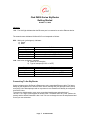
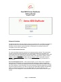
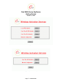
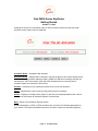
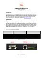
Ctek Z4200 Series SkyRouter
Getting Started
October 11, 2009
Introduction:
Ctek wants to thank you for selecting this Z4200 Series product. We realize that for many of you
this will be your first exposure to Ctek’s product line. Our goal with this document is exactly as the
title suggests, helping you get started. As a first read we believe that the information found here
will serve as a useful quick start and as a pointer to some of the more in depth documentation
found in the product’s User Manual which is available at www.ctekproducts.com.
Connections:
The green connector J1 supports four separate functions, power, relay contact closure detection,
relay driver output, and auxiliary serial port serial data. Contact closure pins 2 and 4 are shared
with the auxiliary serial port. To option remove the circuit board and locate 3-pin headers JP1 &
JP2 behind the green connector. Facing the end of the board containing the green connector JP1
and JP2 should have jumpers center to right to use the discrete I/O (Din, Dout), and JP1 and JP2
should have jumpers center to left to use the auxiliary serial port. Auxiliary serial port parameters
(baud, parity, etc.) are set using the RS232 screen. From the factory the unit ships with the
auxiliary serial port enabled.
.
The J1 pin out configuration is as follows:
Terminal Block Pin
JP1 & JP2 (internal) Center to Right
Pin 1
Pin 2
Pin 3
Pin 4
Pin 5
Pin 6
Din – Discrete Input (See Appendix A)
Din Src – Discrete Input Source
Dout Gnd – Discrete Output Ground
Dout – Discrete Output
Power supply Ground
Power supply +12VDC
Z4200S Connections
Figure 1
Page 1
© 2009 Ctek Inc
JP1 & JP2 (internal) Center to Left
RxD of auxiliary serial port
Ground of auxiliary serial port
TxD of auxiliary serial port
Power supply Ground
Power supply +12VDC
Ctek Z4200 Series SkyRouter
Getting Started
October 11, 2009
Z4200U Connections
Figure 2
Switches and Indicators:
Switches
Referring to Figure 2, there are two switches on the front of the Z Series router. S1 (Reset)
causes a hard reset of unit. S2 (DFLT) is used to completely restore the firmware settings that
were included when the product was shipped from the factory. To restore factory defaults, the unit
must be running. Press the Restore Defaults (inner) switch and hold it down for 10 seconds. After
10 seconds, you will see both the green and yellow lights go off. At that time you may either press
the reset (outer) switch or cycle power on the unit.
Figure 3
Page 2
© 2009 Ctek Inc
Ctek Z4200 Series SkyRouter
Getting Started
October 11, 2009
Indicators
LAN – The LAN light indicates that the Ethernet port is connected to an active Ethernet device.
The network status indicators LINK and SVC are interpreted as follows:
SVC – Multi-color (yellow/green). Indicates:
a) Power
b) RSSI
Display
Definition
Off
Yellow Blinking
Yellow Solid
Green Solid
No Power
Power On – No Signal (RSSI)
Power On – RSSI < -88
Power On – RSSI >= -88
Link - Multi-color (red/green). Indicates:
a) Status of IP connection
b) Type of transport (EV-DO or 1xRTT)
Display
Definition
Off
Green
Red
No Connection (IP address)
Connection established on 1xRTT
Connection established on EV-DO
Connecting To the SkyRouter
Connect a laptop to the SkyRouter’s Ethernet port using a standard Ethernet cable. The factory
default for the SkyRouter is to act as a DHCP server meaning that your laptop should be set up
as a DHCP client. Most laptops used on corporate or home networks will already be configured
as a DHCP client.
To access the Administration menu use a conventional web browser pointed at http://
192.168.1.10. A login screen appears as shown below. The default User ID is “ctek” (without the
quotes) and the default Password is also “ctek”. Be sure to change the user ID and password and
record your new selections.
Page 3
© 2009 Ctek Inc
Ctek Z4200 Series SkyRouter
Getting Started
October 11, 2009
Figure 4
Network Activation
The Wireless Activation Services interface serves two purposes. First, it provides a mechanism to
activate the router on the wireless networks utilizing a form of Over The Air (OTA) activation.
Secondly it may be used as a general interface to send specific commands, known as AT
commands, to the router’s radio module.
Over The Air Activation Overview
For Verizon and Sprint networks activation is as simple as pushing a button. The prerequisites
are that a network account be assigned to your units ESN and that the unit is located in an
environment where the SkyRouter can verify network stability. The network stability criteria is that
during the previous two minute sample period the RSSI is less that (smaller negative number) 99dBm, the SID has not changed, and the unit has access to 1xRTT connectivity. Once the
prerequisites are met the activation button is clicked and the progress may be observed in a
status window.
Over The Air Network Process – If the wireless module in your Z Series router is capable of
performing an OTA activation you will be presented with the option to select the appropriate
activation method. Currently this capability is limited to the OMA-DM method for Sprint-Nextel or
the OTAS method for Verizon Wireless. The Verizon Wireless OTAS also updates the unit’s PRL
and can be redone whenever a new PRL is required. Sprint OMA-DM is capable of downloading
a PRL over the air but the feature is not yet implemented in the network. Because of the
differences in PRL strategies the Verizon Activation Services screen is different than the Sprint
version.
Page 4
© 2009 Ctek Inc
Ctek Z4200 Series SkyRouter
Getting Started
October 11, 2009
Figure 5
Figure 6 (Verizon Wireless)
Page 5
© 2009 Ctek Inc
Ctek Z4200 Series SkyRouter
Getting Started
October 11, 2009
Selecting the Over The Air Activation option on either of these screens will cause the actual
activation screen (Figure 26) to be displayed.
Figure 7
Activation Status – Activated or Not Activated
Network Stability – Indicates OK For Activation if during the previous two minute sample period
the RSSI is less that (smaller negative number) -99dBm, the SID has not changed, and the unit
has access to 1xRTT connectivity. IOTA and OTAS activations do not currently work for
conditions where the connection is EV-DO only.
Activate – Causes the unit to contact the network for an over-the-air activation
Status – Refreshes the current screen so that progress can be monitored.
Details – Displays a scrolling screen (Figure 27) with low level messages between the unit and
the network. Useful when an activation problem is encountered.
Back – Return to the Activation Services screen.
Detailed information on IOTA or OTAS activations are covered in the TechNote appropriate for
your network. The Status and Details buttons can be used to monitor the activations progress.
Page 6
© 2009 Ctek Inc
Ctek Z4200 Series SkyRouter
Getting Started
October 11, 2009
Figure 8
For configuration information on the many features found in the Z4200 see the user manual,
TechNotes, Application Notes, and Technical Information Bulletins available at
www.ctekproducts.com.
Page 7
© 2009 Ctek Inc