1
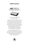
GTQ 360 new
7/17/98 10:44 AM
Page 1
GRAND TOURING SERIES
4/3/2 Channel
Automotive Power Amplifier
GT Q 3 6 0 , GT Q 2 4 0 O w n e r ’ s M a n u a l
GENUINE JBL
GTQ 360 new
7/17/98 10:44 AM
Page 2
1. Introduction . . . . . . . . . . . . . . . . . . . . . . . . . . . . . . . . . . . . . . . . . . . . . . . . . . . . . . . . .
3
1.1 Thanks . . . . . . . . . . . . . . . . . . . . . . . . . . . . . . . . . . . . . . . . . . . . . . . . . . . . . . . . . .
3
1.2 About Installation . . . . . . . . . . . . . . . . . . . . . . . . . . . . . . . . . . . . . . . . . . . . . . . . .
3
2. Installation and Use . . . . . . . . . . . . . . . . . . . . . . . . . . . . . . . . . . . . . . . . . . . . . . . . . . .
2.1
................................................................
3
3
2.2 Controls and Connectors . . . . . . . . . . . . . . . . . . . . . . . . . . . . . . . . . . . . . . . . . . .
4
3. System Design Using the GTQ360 and GTQ240 . . . . . . . . . . . . . . . . . . . . . . . . . . . .
4
3.1 Speaker Requirements . . . . . . . . . . . . . . . . . . . . . . . . . . . . . . . . . . . . . . . . . . . .
4
3.2 Signal Sources . . . . . . . . . . . . . . . . . . . . . . . . . . . . . . . . . . . . . . . . . . . . . . . . . . .
5
4. Wiring . . . . . . . . . . . . . . . . . . . . . . . . . . . . . . . . . . . . . . . . . . . . . . . . . . . . . . . . . . . . . .
5
4.1 Wiring . . . . . . . . . . . . . . . . . . . . . . . . . . . . . . . . . . . . . . . . . . . . . . . . . . . . . . . . . .
5
4.2 Ground Wire . . . . . . . . . . . . . . . . . . . . . . . . . . . . . . . . . . . . . . . . . . . . . . . . . . . . .
5
4.3 Remote-In/Out Connection . . . . . . . . . . . . . . . . . . . . . . . . . . . . . . . . . . . . . . . . . . 5
Owner’s Warranty Information
4.4 Mute Connection . . . . . . . . . . . . . . . . . . . . . . . . . . . . . . . . . . . . . . . . . . . . . . . . . . 7
4.5 Speaker-Level Input Harness . . . . . . . . . . . . . . . . . . . . . . . . . . . . . . . . . . . . . . . . 7
Model Number
5. Internal Adjustments . . . . . . . . . . . . . . . . . . . . . . . . . . . . . . . . . . . . . . . . . . . . . . . . . . 7
5.1 Speaker-Level Input Impedance Adjustments . . . . . . . . . . . . . . . . . . . . . . . . . . 7
5.2 Crossover Frequency Adjustments . . . . . . . . . . . . . . . . . . . . . . . . . . . . . . . . . . . 7
Serial Number
Dealer Name
5.3 Custom Chip Construction . . . . . . . . . . . . . . . . . . . . . . . . . . . . . . . . . . . . . . . . . . 7
6. Adjusting the Gain . . . . . . . . . . . . . . . . . . . . . . . . . . . . . . . . . . . . . . . . . . . . . . . . . . . . 8
City, State, Zip
7. Typical Applications . . . . . . . . . . . . . . . . . . . . . . . . . . . . . . . . . . . . . . . . . . . . . . . . . . . 8
8. In Case of Difficulty . . . . . . . . . . . . . . . . . . . . . . . . . . . . . . . . . . . . . . . . . . . . . . . . . . . 10
Sales Receipt Number
Specifications . . . . . . . . . . . . . . . . . . . . . . . . . . . . . . . . . . . . . . . . . . . . . . . . . . . . . . . . . . 11
Warranty Terms . . . . . . . . . . . . . . . . . . . . . . . . . . . . . . . . . . . . . . . . . . . . . . . . . . . . . . . . 12
2
Date of Purchase
GTQ 360 new
7/17/98 10:44 AM
Page 3
1. Introduction
1.1 Thanks for purchasing your new
GT series automotive multi-channel
amplifier. Your GT series amplifier will
easily connect to virtually any car audio
system, whether it is factory installed or
purchased separately. The GTQ360 and
GTQ240 include an abundance of unique
features which are described in this manual. The flexible design of their built-in
crossover circuitry allows elaborate systems to be built more simply than with
conventional components. For optimum
performance, the power amplifier circuitry is a fully-discrete design notable for its
low distortion and unusually clean and
clear sound quality.
In addition to conventional preamp-level
inputs, the GTQ360 and GTQ240 feature
JBL’s Universal Interface™ design, which
facilitates simple connection to factory
radios with the low distortion that is usually only associated with preamp level
connection. With the Universal Interface
on the GTQ360 and GTQ240, a factory
radio can either be used as the main
music source or simultaneously combined with a CD player or changer that
has volume-control capability. By providing this two-unit direct connection,
Universal Interface circuitry eliminates the
need for an FM modulator to interface a
CD player to factory radios, improving the
fidelity of digital playback.
In addition, when using a high-powered
(BTL) radio through the speaker-level
inputs, Common Sense turn-on circuitry
senses the common-mode voltage present on the radio’s speaker wires, turning
the amplifier on without an additional
remote wire.
2. Installation and Use
Also, the built-in active cross-over provides either full-range, high-pass or lowpass operation. This lets your GT series
amplifier power either subwoofer or component speakers in a bi-amplified system,
or conventional full-range speakers in
simpler systems.
The GTQ360 and GTQ240 also include
preamp-level outputs which can provide
either full-range, high-pass or low-pass
signal to drive additional amplifiers. This
lets you build systems of virtually any
design without requiring a separate electronic crossover.
1.2 About Installation
Although the GTQ360 and GTQ240 are
designed to make installation as easy as
possible, these are extremely sophisticated products that require proper installation and setup to realize their full performance potential. If you feel you do not
have the necessary knowledge and skills,
we strongly recommend that the installation be done by your authorized JBL dealer.
If you choose to install the GTQ amplifier
yourself, read all of the information in this
manual before you start the installation.
Pay particular attention to the safety precautions and notes.
2.1 Refer to the “Speaker-Level Input
Impedance Adjustments” and “Crossover
Frequency Adjustments” sections of this
manual (page 7) to see if you will need to
make alterations to the factory settings. If
you are not using the built-in crossover,
or the speaker-level inputs, you may skip
this step.
1. Disconnect the negative cable from the
battery. Note: If the vehicle’s radio features a code-type security system, make
certain you know the code before disconnecting the battery!
2. Run a power cable complete with a
fuse (not included) directly from the positive +12V battery terminal to the desired
amplifier location. Keep the fuse within 6"
of the battery terminal, and position it
before the wire runs through any metal
partition. A minimum of #10AWG is
required for the GTQ240 and #8AWG for
the GTQ360. The GTQ240 requires a 30A
fuse, the GTQ360 a 60A fuse.
Note: All wiring connections should be
made either by soldering with heatshrink
tubing insulation, by using commercially
available high-quality distribution blocks,
or with high-quality crimp-type insulated
connectors installed with a professionaltype, articulated crimping tool. Soldering
crimp-type terminals is recommended for
additional security. Never use wire nuts,
insulation-displacement connectors (i.e.,
ScotchLok type), or twist and tape connections. Do not use electrical tape; it will
loosen with age and extreme
temperatures.
3. Mount amplifier in the desired location
using the included screws.
4. Connect power wiring as shown in the
Wiring Diagram.
5. Connect the outputs from the head unit
to the appropriate inputs of the amplifier
according to the Wiring Diagram with
either (or both) high-quality low-level signal cables with RCA plugs, or the supplied
speaker-level input connector.
6. Connect the speakers to the amplifier
according to the Wiring Diagram.
7. Turn the gain controls to the
1/4-position for all groups.
8. Set the bass boost of each group to the
desired position.
9. Set the crossover switches for each
group as desired.
10. Set the Group 2 Input as desired.
11. Set the mode switches to Stereo,
Left + Right, or Left Input Only operation
for each group.
12. Double-check your switch settings.
Reconnect the negative battery cable.
Note: Incorrect switch settings can damage your speakers!
13. Turn on the signal source at a low volume level, and check for the correct output from each speaker.
14. Adjust the amplifier gain controls
using the procedure described in the
“Adjusting the Gain” section.
15. Read the rest of the manual to get
maximum use and enjoyment from your
amplifier.
3
GTQ 360 new
7/17/98 10:44 AM
LINE LEVEL
INPUT
GR2
GR1
GR1
PREAMP
OUTPUTS
GR2
Page 4
SPEAKER LEVEL INPUTS
R GR2 L
+ –
– +
L
+
SPEAKER OUTPUTS (BRIDGED: R+TOL–)
GR1
R
L
GR2
R
+
+
+
FUSE
30A
FUSE
30A
REM
IN/OUT
POWER
MUTE
BASS EQ
OFF ON
CROSSOVER
SPEAKER
PREAMP
H F
R ST L+R
–
1
2
3
2.2 Controls and Connectors
1. Preamp-Level Input Connector – Use
these connectors for line-level (preamp)
inputs to the amplifier.
2. Preamp-Level Output Connector – Use
these outputs to send signal to additional
amplifiers.
3. Speaker-Level Input Connector – Use
this connector for speaker-level input signals. A wire harness is supplied for use
with this connector. This input also
includes JBL’s Common Sense input circuitry which turns the amplifier on as
soon as the high-powered head unit connected to this input is turned on.
4. Speaker Output Connectors – Connect
speaker wiring to these connectors. See
wiring directions for more information.
5., 6., 7., 8. Power Connector –
Connection for power wires REM IN/OUT
and Mute. See wiring directions for information on proper connections.
9. Fuses – GTQ240: 30A ATC type.
GTQ360: 2 x 30A ATC type.
10. Gain Controls – Use these controls to
adjust the gain of the amplifier channel
group. See the “Adjusting the Gain” section for tips on proper setup.
–
–
4
9
BASS EQ
OFF ON
MODE
GND
5
6
7
8
11. Preamp Crossover Switches – These
switches control the built-in crossovers
that are directed to the preamp-output
connectors. Set the switch to F (flat) for
full-band operation for that group. Set the
switch to L (low) to activate the low-pass
filter on the pre-amp output group (for
subwoofer use or to use in conjunction
with a high-pass filtered input signal to
create a band-pass crossover for a
midrange or midbass driver). Set the
switch to High-Pass to activate the highpass filter for use with satellite speakers
or tweeters on the pre-amp output group.
12. Speaker Crossover Switches – These
switches control the built-in crossovers
that are connected to each group's power
amplifier circuitry. Set the switch to F
(flat) for full band operation on a group.
Set this switch to L (low) to activate the
low-pass filter on the selected amplifier
group for subwoofer use or to use in conjunction with a high-pass filtered input
signal to create a band-pass crossover
(for a midrange or midbass driver). Set
the switch to H (high) to activate the highpass filter for use with satellite speakers
or tweeters on an amplifier group.
GROUP 1
14
13
12
11
CROSSOVER
SPEAKER
PREAMP
F
R ST L+R
MIN MAX
GAIN
BATT(+)
–
INPUT
GR1 GR2
H
L
L
30A
30A
+ –
– +
R GR1 L
R
4
MODE
F
L
10
15
13. Mode Switches – These switches are
used to set the input mode for both preamp and speaker-level inputs. Set the
switch to ST(ereo) for normal operation
on the group using individual left and
right inputs. Set this switch to R to drive
both the left and right outputs with only a
single input on the right jack. Set the
switch to L+R to sum the left and right
inputs for a mono output on the group.
These switches do not affect the preamp
ouputs.
14. Bass EQ Switch – These switches activate a built-in Bass Boost circuit used to
increase low-bass output on the selected
group. These switches do not affect the
preamp outputs.
15. Group 2 Input Switch – This switch is
used to select which inputs will drive
Group 2 of the amplifier. Put the switch in
position “GR 1” to allow Group 2 to be
driven by the Group 1 inputs. Put the
switch in the “GR 2” position to drive
Group 2 with the Group 2 inputs.
Power Indicator LED (on amp chassis
top) – LED steadily illuminates for normal
operation. LED blinks when protection
circuitry or muting is engaged.
14
13
H F
H
L
L
CROSSOVER DESIGNATIONS
F = FLAT (BYPASS)
L = LOW PASS
H = HIGH PASS
GROUP 2
12
11
MIN MAX
GAIN
10
3. System Design Using
the GTQ360 and GTQ240
3.1 Speaker Requirements
When used in the non-bridged mode, a
group-channel of the GTQ360 or GTQ240
can easily drive two 2-ohm speaker loads.
When only one speaker is connected to
the left and right outputs of a group, virtually any conventional speaker may be
used. Although the amplifier will not be
damaged, load impedances lower than 2
ohms will eventually cause the amplifier
to overheat, activating the protection circuits and causing the unit to shut off until
it cools down sufficiently.
When a group is in bridged mode, the
combined impedance of the speaker (or
speakers) connected to the bridged channels should be at least 4 ohms. Sustained
operation of the unit in bridged mode
with less than 4 ohms will likely cause
overheating.
The GTQ360 or GTQ240 must not be used
with speakers that have either one of
their input terminals wired to the frame
of the speaker or to the chassis of the
vehicle.
GTQ 360 new
7/17/98 10:44 AM
Page 5
4.3 Remote-In/Out Connection
4. Wiring
4.1 Wiring
3.2 Signal Sources
Parallel Wiring
(+)
2 ohms
Nominal
Impedance
4 ohms
4 ohms
(–)
Series Wiring
(+)
4 ohms
8 ohms
Nominal
Impedance
(–)
4 ohms
The low-level preamp outputs of any
radio/tape deck, CD player, or preamp/
equalizer so equipped can drive the
GTQ360 or GTQ240. The gain controls of
the amplifier are used to match its input
sensitivity to the output voltage of the
source. This matching is important to
keep noise low and is explained in the
“Adjusting the Gain” section of this
manual.
Thanks to Universal Interface Circuitry,
the GTQ360 or GTQ240 can also be connected to power amplifiers, radios or
equalizers that are equipped with only
speaker outputs by connecting them
through the speaker-level input connector. Inside the GTQ360 and GTQ240, the
speaker-level and preamp-level inputs are
connected through a mixing circuit, which
allows them to be used simultaneously.
Therefore a low-level source, such as a
CD player equipped with a volume control, may be connected to the preamplevel inputs at the same time as a powered radio/tape unit is connected to the
speaker-level inputs. This provides a higher performance alternative to an FM modulator connection when you wish to add
CD capability to a factory cassette stereo.
Switching from one source to the other is
as simple as turning the desired source
on and turning the undesired one off —
no additional switches or relay connections are needed.
Proper wiring of the GTQ amplifiers and
the associated components is extremely
important for proper performance and
long-term reliability. Using the proper
type of wire is very important.
Route the wiring through the car carefully.
Do not allow wires to lay against sharp
sheet metal edges or any other surfaces
that might wear away or cut through the
insulation of the wire. Use insulated strain
reliefs, rubber grommets and plastic tubing to protect the wires whenever they are
run through sheet metal panels or are
placed where they might be pulled or
damaged.
4.2 Ground Wire
• Proper grounding is extremely important. Use a heat- and oil-resistant stranded
copper automotive wire equivalent to the
size used for the +12V connection. Crimp
or solder and insulate any wire-to-wire
connections. Keep the ground wire as
short as possible. A ground wire must be
solidly connected to a major sheet-metal
structure of the vehicle such as a panel
near the amp-mounting location. Scrape
all paint and primer off the sheet metal at
the grounding point to ensure a good
electrical connection. Attach the wire to
the grounding point with a nut, bolt and
star washer. The high current demanded
by high-powered amplifiers requires a
more secure ground than the typical
sheet-metal screw will provide. Coat the
connection with silicon sealant for better
long-term reliability.
• The remote power control system turns
the GTQ amplifier off when not in use to
prevent discharging of the vehicle’s battery. Because the JBL GTQ amplifiers
include Common Sense 2-way turn-on,
when using the speaker-level inputs with
a head unit that includes a BTL power
amp it is not necessary to connect the
remote wire. The amplifier will automatically activate whenever you turn on the
head unit. If you are using the line-level
inputs, or the speaker-level inputs with a
head unit that does not have a BTL power
amp, use the following remote wire connections.
• Using the REM-IN feature – When +12
volts is applied to the remote IN/OUT terminal the amplifier is turned on. A red
LED on the top panel of the amplifier will
illuminate to indicate the amplifier is on.
If the head unit has a +12 volt automatic
antenna or amplifier remote activation
wire, connect it to the REM-IN/OUT connector on the GTQ amplifier. When the
amplifier is turned on, there is a time
delay of several seconds (longer in cold
weather) before the amplifier will produce
sound. This eliminates the chance of
annoying noises produced by the radio or
signal processors being amplified and
passed to the speakers when the system
is first activated.
• Some head units have no automatic
antenna or power amp activation wire.
Others have automatic antenna wires that
are “on” only when the radio is used but
not when a tape is played. In such cases,
connect the remote-in turn-on terminal to
an unused accessory terminal in the fuse
block, or any other +12 volt source that is
turned on and off with the vehicle’s ignition switch. The remote on/off system
5
GTQ 360 new
7/17/98 10:44 AM
Page 6
Tweeter/Midrange Satellites
(High-Pass)
Left
C: 300µF capacitor
100V, non-polarized
Subwoofer Low-Pass
Crossover Frequency: 100Hz
Antenna Input
Power
Antenna
(+)
(–)
High-Pass Satellite
Crossover Frequency: 100Hz
CD Player
or Changer
Cassette/CD Tuner
Subwoofer (Low-Pass)
A. Satellite/Subwoofer
Cassette/CD Tuner
Speaker-Level Output Connection
(Use only when line-level output
is not available)
L:
CD Input
(+)
(–)
Right
(+)
L
C
(–)
C
6.2mH air core inductor
Amplifier
Speaker
Level
Inputs
Cassette/Receiver
Power Supply
Wires
GTQ360
Fuse
Fuse
Red - Main +12V
LINE LEVEL
INPUT
GR2
GR1
PREAMP
OUTPUTS
GR1
GR2
R
+
+ –
– +
R GR1 L
R
FUSE
30A
REM
FUSE IN/OUT
30A
POWER
MUTE
–
–
Speakers
High-Pass (Satellite Crossover):
Amplifier
Speaker
Output
Connection
Ignition Switch
+
+
–
Main +12V
–
–
BATT(+)
GND
30,000
Desired crossover Frequency in Hz = New Capacitor Value in µF
620
Low-Pass (Subwoofer Crossover): Desired crossover Frequency in Hz = New Inductor Value in mH
(Not Included)
Fuse
–
*You may change the subwoofer satellite crossover frequency by using the
Inductor and Capacitor values calculated with the following formulas:
+
Blue w/White Stripe - Remote On/Off
–
SPEAKER LEVEL INPUTS
SPEAKER OUTPUTS (BRIDGED: R+TOL–)
R GR2 L
L
GR1
R
L
GR2
+
+ –
– +
+
+
L
Yellow - Back Up Power
Remote On/Off
Remote Antenna
Black - Power Ground
Power
Supply
Blue (Blue/White)
Antenna
Motor
Amplifier
Speaker
Output
Connection
30A
Cassette/CD Preamp Output
Amplifier
Power
Connection
30A
Power
Antenna
Relay
Speakers
Center Channel
Bridged Speaker Connection*
B. Center Channel
+
Amplifier
Speaker
Output
Connection
Vehicle Battery
+
)–(
)+(
8 Ω Minimum
8 Ω L-Pad
(Optional but Recommended)
Power Ground
GTQ360
Chassis Ground
GR2
SPEAKER LEVEL INPUTS
SPEAKER OUTPUTS (BRIDGED: R+TOL–)
R GR2 L
L
GR1
R
L
GR2
+
+ –
– +
+
+
R
+
FUSE
30A
REM
FUSE IN/OUT
30A
30A
PREAMP
OUTPUTS
GR1
30A
LINE LEVEL
INPUT
GR2
GR1
POWER
MUTE
L
+ –
– +
R GR1 L
R
draws negligible current so a relatively
small (18 or 20 gauge) wire may be used.
• Using the REM-OUT feature – The REMIN/OUT terminal of the GTQ amplifier
may be used to turn on other amplifiers
when the GTQ amplifier is being turned
on by the Common Sense circuitry in the
speaker-level input. Simply connect the
6
head unit speaker-level outputs to the
GTQ amplifier speaker-level inputs and
connect the REM-IN/OUT terminal to the
remote-in terminal of other amplifiers or
signal processors. The GTQ amplifier will
turn on the other amps or processors
whenever the Common Sense circuitry
turns on the GTQ amplifier.
–
–
–
–
BATT(+)
* Center Channel Speaker Minimum 8 Ohms, Main
Speakers Minimum 4 Ohms When Used Simultaneously.
Stereo, Non-Bridged
Speaker Connection*
)+(
)–(
4Ω Minimum
)–(
)+(
4Ω Minimum
Simultaneous Stereo-Mono Connection Diagrams
GND
GTQ 360 new
7/17/98 10:44 AM
Page 7
5. Internal Adjustments
5.1 Speaker-Level Input
Impedance Adjustments
4.4 Mute Connection
The GTQ amplifier includes a mute input
terminal. This amplifier will mute when a
5V to 12V DC signal is applied to the
“mute” input and will be in normal operation mode with either a ground or nothing connected to the “mute” input. This
“mute” input is compatible with any
aftermarket noise gate that puts out a
control voltage of +5V to +12V DC.
4.5 Speaker-Level Input
Harness
Color Codes
Group 1 Left (+):
Group 1 Left (–):
Group 1 Right (+):
Group 1 Right (–):
Group 2 Left (+):
Group 2 Left (–):
JUMPER SELECTOR
SELECT 100K OR 15 OHMS
100K
15Ω
T
PU
NE
LI
T
BA
30
30
Group 2 Right (+):
Group 2 Right (–):
White
White with
Black Stripe
Gray
Gray with
Black Stripe
Green
Green with
Black Stripe
Purple
Purple with
Black Stripe
The speaker level inputs of the GTQ
amplifiers come factory-set with
100k ohm input impedance. This will provide the lowest distortion operation from
the speaker outputs of most modern head
units by reducing the power the amplifier
in the head unit must deliver to practically, nothing. On some older or lowerpriced head units this load will not facilitate proper fader operation. To allow for
this, we have provided the ability to
change the input impedance of the speaker-level inputs to 15 ohms. This is accomplished by moving the jumpers shown on
the diagram below. This input is also
capable of directly accepting signals,
when in the 100k ohm setting, from many
Balanced Line Drivers such as those
sometimes used in competition vehicles.
If the head unit has 4 channels of built-in
amplification and/or an electronic fader
control, you should leave the jumpers in
the factory-set position.
If the head unit has 2 channels of amplification, with a speaker-level fader, the
jumpers should be set to the 15-ohm
position. This will always be a rotary-type
control, not one controlled by electronic
pushbuttons.
D
GN
M
RE T
OU
IN
5.2 Crossover Frequency
Adjustments
The GTQ amplifiers include built-in
frequency selectable crossovers. One
crossover is connected in series with the
amplifier circuitry and the other crossover is connected to the preamp level output jacks. These crossovers can be set in
either the “F” (full bandwidth operation),
“L” (subwoofer operation), or “H” (satellite operation).
The crossover frequencies are set by
chips inside the amplifier. These chips are
simply a set of resistors, connected
across the pins and molded into a single
package. The crossover frequencies may
be changed to any value desired by
changing the resistor network. JBL has
chips available in the popular values listed in the table which follows. If none of
these suit your system, you may purchase
compatible resistor networks from a local
electronics store, or you may build your
own custom values from discrete resistors mounted on a 14-pin DIP Header
using the instructions which follow.
Frequency
Resistor
Value
JBL Part
Number
50Hz
80Hz
120Hz
200Hz
250Hz
375Hz
500Hz
650Hz
2.5kHz
5kHz
47k Ω
33k Ω
22k Ω
12k Ω
10k Ω
6.8k Ω
4.7k Ω
3.9k Ω
1k Ω
470 Ω
1-23-750
1-23-817
1-23-820
1-23-821
1-23-810
1-23-822
1-23-815
1-23-823
1-23-824
1-23-816
5.3 Custom Chip Construction
Regardless of whether you build or buy it,
the necessary resistor network has the
following configuration:
• Each resistor in the package has the
same value.
• If you know the crossover frequency you
want, you can calculate the resistor value
necessary by solving the following equation:
Resistor
Value =
in ohms
2,500,000
Frequency in Hz
• Use the following equation if you have a
resistor pack of a known value, and want
to find its crossover frequency:
2,500,000
Frequency
= Resistor Value in ohms
in Hz
• To build chips from discrete resistors,
solder the resistors to a standard 14-pin
“DIP Header” according to the diagram. If
a DIP Header is not available, you may
bend the leads of 1⁄4-watt resistors 90
degrees, trim them to 3mm-length, and
insert them directly into the chip sockets.
7
GTQ 360 new
7/17/98 10:44 AM
Page 8
BEST-Vertical Mounting
HIG
H
FR FILTEPASS
SE EQUE R
C1
LE
3
MO CT NCY
DU ION
LE
C1
0
DU ION Y
LE
LO
W
FR FILTEPASS
SE EQUE R
LE
MO CT NC
CR
OS
SO
VE
R
NO JB
RTH L
JB R INC.
PC L GTSIDGE,
00 60 C
REV1088 0 A
A 00
2. Select which resistor module, high
pass or low pass, that you wish to
change.
3. A chip puller, which can be obtained
from any electronics store, is recommended to remove the resistor chip. Pull
the resistor chip from the socket as
shown in the figure below.
4. Place the new module in the socket
making sure all pins are lined up with the
socket holes. Press the module firmly into
the socket.
5. Replace the bottom lid.
For further information on how to use the
speaker output and preamp output
crossovers for system building see the
“Typical Applications” and “Add-On and
Upgrade Steps” sections.
8
AIR FLOW
6. Adjusting the Gain
Before operating the GTQ amplifiers,
recheck all wiring connections to make
sure they are correct and secure. Be sure
that a fuse (not included) is installed in the
+12V line near the battery. Reconnect the
negative ground (–) terminal of the battery. Make sure that the mode switches,
crossover switches, Group 2 Input switches, and crossover frequency modules are
properly set.
• The setting of the gain controls on the
GTQ amplifiers is important to ensure
proper performance, low noise levels, and
maximum reliability in the system.
Using a high signal level from the source
and a low gain setting on the amplifier
will help keep background noise levels in
the system low.
• To adjust a system using a single GTQ
amplifier, start with both of the amplifier
gain controls fully counterclockwise. Set
all bass/treble or equalizer controls to
their centered or bypassed positions.
While listening carefully to the system
output, adjust the volume control of the
radio/tape deck to the point where you
first begin to hear audible distortion.
Use caution: excessive distortion can
damage loudspeakers. Reduce the level
just to the point where the distortion goes
away. If this setting does not provide adequate volume levels, gradually increase
(turn clockwise) the gain control for the
main (usually front) speaker groups on
the GTQ amplifier until the system plays
as loud as necessary or when the first
signs of distortion are heard.
7. Typical Applications
The following diagrams show the most
common basic system configurations of
the GTQ amps. One or more of these
building blocks may be combined to form
elaborate system designs.
The GTQ amps use the terminology
“Group 1” and “Group 2” to indicate the
two main signal paths within the amplifier. Each “group” may consist of a mono
bridged signal or a stereo pair of L+R
signals depending on the system
configuration.
GOOD-Horizontal Mounting
AIR FLOW
NEVER-Mount Upside Down
System 1
Active 3-way using outboard tweeter amplifier
GR 1
GR 2
Speaker Preamp Group
Output Output
2
Mode CrossoverCrossover Input X-over Frequency
Stereo Low
High
—
5k**
Stereo Low
High GR 2
80Hz**
Front
* A single (mono) subwoofer may be used by setting GR 2
mode to "L+R."
** The crossover frequencies listed are suggestions. Actual
crossover points should be determined from
loudspeaker requirements.
GR 1 GR 2 GR 2
Pre Out Input Pre Out
Input
LOW-POWER
STEREO AMP
GR 1
Input
GTQ AMP
GR 1
–
+
+
–
,,
,,
To change the crossover frequency
change the resistor network as follows:
1. Remove the screws from the bottom
panel as shown below.
R
L
Tweeters
–
+ –
L
R
Midbass
+
GR 2
+
– +
L
R
Subwoofers*
–
GTQ 360 new
7/17/98 10:44 AM
Page 9
L R
L R
Preamp or
Front Speaker-Level Rear
Input
L R
L R
Application 1
4-Channel Full-Range
GR 1
Input Mode
Group 2 Input
Speaker Crossover
Preamp Output Crossover
Group 1
ST
–
Flat
–
Group 2
ST
GR 2
Flat
–
4-Channel Bi-Amplified System with
Non-Fading Subwoofers
GR 2
Mode
Group 2 Input
Speaker Crossover
Preamp Crossover
GTQ
AMP
GR 2
GR 1
L–
L+
R–
–
+ –
L
L–
R+
L+
R–
Group 1
Stereo
–
High Pass
–
GR 1
Group 2
Stereo
GR 1+2
Low Pass
–
+
–
+ –
L
R
GR 1
L–
L+
L–
R–
–
+
+ –
L
R
GR 2
GTQ
AMP
R+
GR 2
L+
R–
R+
R+
+
–
+ –
L
R
+
R
Subwoofers
Front Speakers
Rear Speakers
Front Speakers
Application 4
Application 2
3-Channel Bi-Amplified System with
Non-Fading Mono Subwoofer
Mode
Group 2 Input
Speaker Crossover
Preamp Crossover
L R
L R
Preamp or
Front Speaker-Level Rear
L R Input L R
Application 3
Group 1
Stereo
–
High Pass
–
2-Channel Bridged
L R
L R
Preamp or
Front Speaker-Level Rear
Input
L R
L R
GR 1
Group 2
L+R
GR 1+2
Low Pass
–
GR 2
Input Mode
Group 2 Input
Speaker Crossover
Preamp Output Crossover
GTQ
AMP
GR 1
L–
R–
–
+ –
L
+
Group 2
R
GR 2
*
–
R+
R
GTQ
AMP
GR 1
L–
–
+
L R
R
GR 1
R+
R
Front Speakers
Satellite Speakers
Group 1
R
–
*
–
*Set to Low Pass for subwoofers, High Pass for satellites
or Flat for full range.
GR 2
L–
L+
Output
2-Channel Input
–
+
L
GR 2
GR 2
R+
L–
R+
–
+
R
Subwoofer
9
GTQ 360 new
7/17/98 10:44 AM
Page 10
8. In Case of Difficulty
Power-on light does not come on
• Head unit not on; turn the head unit on.
• Ground wire is disconnected or defective; check for continuity with an ohmmeter between the amplifier’s ground terminal and a known chassis ground point.
• Battery wire is disconnected or defective; check for approximately +12 volts
between the amplifier’s battery and
ground terminals.
• Blown fuse; check amplifier’s fuses
located on the end panel near the power
connector. If they are blown, replace them
with identical ones. If the new fuses blow
immediately, check all the wiring connections. If the source of the problem cannot
be determined, consult your JBL dealer.
• Remote-on wire between the head unit
and the amplifiers is disconnected or
defective; check for +12 volts between
amplifier's remote-on input terminal and
the ground wire with the head unit on.
Power light is on, but no sound is heard
from some or all of the speakers
• Incorrect switch settings; make sure that
all switches (mode, input and crossover)
are in their correct positions for your system configuration.
• Incorrectly connected or shorted speaker
wires; check for shorts in wiring.
• Defective or disconnected audio cables;
check for continuity and replace if
necessary.
• Incorrect gain adjustment; verify that the
amplifier gain controls are not turned
completely down. If they are, sound output level may be very low and may give
the impression that the system (or part of
the system) is dead.
10
Power light is on, but no sound is heard
from some or all of the speakers
• Defective head unit or signal processor;
check each component for proper wiring
and operation.
• Defective GTQ amplifier; if there is audio
signal present at the inputs of the amplifier and there is no output, the GTQ amplifier may be defective.
Alternator whine through the audio system with the engine running
• Ground loops; follow the wiring suggestions in the section called “Solving Noise
Problems.” Also, verify that the chassis
grounding point you have chosen is true
ground by checking for continuity
between the chassis ground point and
battery ground.
Bass output from speakers too low
• Speaker wired out of phase; check for
proper polarity on all speaker wiring (+
amp terminal to + speaker terminal and –
amp terminal to – speaker terminal).
Power light is blinking and no sound is
heard
• Incorrectly connected or shorted speaker
wires; check for shorts in wiring.
• Defective GTQ amplifier; if there is no
short on the speaker outputs, the GTQ
amplifier may be broken. Consult your
JBL dealer.
GTQ 360 new
7/17/98 10:44 AM
Page 11
Specifications
Power Output
(20Hz – 20kHz,
14.4V Battery Voltage)
GTQ360
GTQ240
60 Watts x 4 (4 Ohms, 0.05% THD)
90 Watts x 4 (2 Ohms, 0.08% THD)
180 Watts x 2 (Bridged 4 Ohms, 0.08% THD)
45 Watts x 4 (4 Ohms, 0.05% THD)
60 Watts x 4 (2 Ohms, 0.08% THD)
120 Watts x 2 (Bridged 4 Ohms, 0.08% THD)
Signal-to-Noise Ratio
100dBA
100dBA
Frequency Response
10Hz – 50kHz (+0, –1dB)
20Hz – 20kHz (+0, – 0.1dB)
10Hz – 50kHz (+0, –1dB)
20Hz – 20kHz (+0, – 0.1dB)
Damping Factor
> 200
> 200
Slew Factor
>5
>5
Line-Level Input Sensitivity
(For Rated Power)
100mV – 4V RMS
100mV – 4V RMS
Line-Level Input Impedance
10k Ohms
10k Ohms
Speaker-Level Input Impedance
15 Ohm or 100k Ohm
(Selectable by Internal Jumpers)
15 Ohm or 100k Ohm
(Selectable by Internal Jumpers)
Speaker-Level Input Sensitivity
200mV – 8V RMS
200mV – 8V RMS
Preamp Output Level
Preamp Input:
Speaker Input:
V out = V in
V out = 1/2 V in
V out = V in
V out = 1/2 V in
Minimum Speaker Impedance
Single-Ended (Non-Bridged):
Bridged:
2 Ohms
4 Ohms
2 Ohms
4 Ohms
18dB per Octave Low-Pass Filter,
Frequency Chips Available from 50Hz – 5kHz
Factory Setting: 80Hz
18dB per Octave High-Pass Filter,
Frequency Chips Available from 50Hz – 5kHz
Factory Setting: 80Hz
18dB per Octave Low-Pass Filter,
Frequency Chips Available from 50Hz – 5kHz
Factory Setting: 80Hz
18dB per Octave High-Pass Filter,
Frequency Chips Available from 50Hz – 5kHz
Factory Setting: 80Hz
Built-in Electronic
Crossover Frequency and Slope
Bass Boost Frequency and Magnitude
+4dB at 40Hz
+4dB at 40Hz
Mute Trigger Voltage
5V to 12V
5V to 12V
Power Requirement
11 to 16V DC Negative Ground
11 to 16V DC Negative Ground
Fuse Size
30 Amp ATC Type Fuse (2 per Amplifier)
40 Amp ATC Type Fuse
Size (HxWxL)
2 x 11-1/4 x 14"
(51 x 286 x 356mm)
2 x 11-1/4 x 12"
(51 x 286 x 305mm)
Weight
13.5 lbs (6.12 kg)
11.1 lbs (5.03 kg)
Speaker-Level Input
Molex Mini-Fit Jr
Molex Mini-Fit Jr
Mating Connector
#39-01-2080
Metal Pins: 39-00-0038
#39-01-2080
Metal Pins: 39-00-0038
11
GTQ 360 new
7/17/98 10:44 AM
Page 12
Declaration of Conformity
Warranty Terms:
1 Year Transferable Limited Warranty / 2 Year Extended Transferable Limited Warranty (USA Only)
We, JBL Europe A/S
Kongevejen 194B
DK-3460 Birkerød
DENMARK
This is an important document.
Attach your bill of sale to
this page and keep it in a safe
place. Your bill of sale is your
warranty.
Except as specified below, the JBL warranty
covers all defects in material and workmanship. The following are not covered:
Damage caused by accident, misuse, abuse,
product modification or neglect; damage
occurring during shipment; damage from
failure to follow instructions contained in
EN 50 082-1/3.1995
the instruction manual; damage resulting
from the performance of repairs by someone not authorized by JBL; damage caused
by installation of parts that do not conform
to JBL specifications; units used for commercial or business use; any claims based
on misrepresentations by the seller; products sold on an “as-is” or final sale basis; or
the cost of installing, removing, or reinstalling the unit. JBL’s liability is limited to
the repair or replacement, at our option, of
any defective product and shall not include
incidental or consequential damages. JBL
reserves the right to replace a discontinued
model with a comparable model. Any
replacement units or parts may be new
or rebuilt.
To Obtain Warranty Service
If you require warranty service, please
return the product to your dealer. If this is
not possible and you live in the United
States, please call 1-800-336-4JBL for
information on how to obtain service or
replacement. If purchased outside the
United States, contact your local dealer for
repair or replacement.
Do Not Return Products to
the JBL Factory without
Authorization. They will be
Returned Unopened.
Steen Michaelsen
JBL Europe A/S
Birkerød. DENMARK. 5/97
You are responsible for transporting your
product for repair or replacement. JBL will
pay reasonable return charges for delivery
to any location in the United States if the
repair or replacement is covered under
the warranty.
Correspondence with JBL should be
addressed to: JBL Customer Service, 80
Crossways Park West, Woodbury, NY 11797
or fax us at 516-496-0812. Outside the
United States, please contact your local
distributor.
This warranty gives you specific legal rights.
You may also have other rights which vary
from state to state. Some states do not
allow the exclusion or limitation of
incidental or consequential damages or limitations on how long an implied warranty
lasts, so the above may not apply to you.
JBL Consumer Products
80 Crossways Park West
Woodbury, NY 11797
8500 Balboa Blvd.
Northridge, CA 91329
800-336-4JBL (4525)
A Harman International Company
Part No. GTQ360/240OM
Made in USA
0
EB
RAT
I
NG
What is Covered by
this Warranty
EN 55 020 /6.1988
5
The JBL warranty protects the original
owner and all subsequent owners providing
that the JBL product was purchased from an
authorized dealer in the United States or
purchased by military personnel from an
authorized military outlet. A copy of the
original dated bill of sale must be presented
whenever warranty service is required.
standards:
S
Who is Protected by
this Warranty
in this owner’s manual are in compliance with technical
CEL
The JBL warranty remains in effect for one
year from the date of the first consumer
purchase unless installed by an authorized
JBL dealer. Installation by an authorized JBL
dealer will extend the warranty to a period
of two years.
declare in own responsibility, that the products described
YEAR