1
Instruction Manual
HAS60E-IM-HW
06/2007
Instruction Manual
Chemiluminescence Detector
CLD Analyzer Module (combined with NGA 2000 Platform,
MLT, CAT 200 or TFID Analyzer)
1st Edition 06/2007
www.EmersonProcess.com
CLD Chemiluminescence Detector
Instruction Manual
HAS60E-IM-HW
06/2007
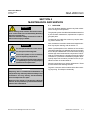
ESSENTIAL INSTRUCTIONS
READ THIS PAGE BEFORE PROCEEDING!
Emerson Process Management (Rosemount Analytical) designs, manufactures and tests
its products to meet many national and international standards. Because these instruments
are sophisticated technical products, you MUST properly install, use, and maintain
them to ensure they continue to operate within their normal specifications. The following
instructions MUST be adhered to and integrated into your safety program when installing,
using and maintaining Emerson Process Management (Rosemount Analytical) products.
Failure to follow the proper instructions may cause any one of the following situations to
occur: Loss of life; personal injury; property damage; damage to this instrument; and warranty
invalidation.
• Read all instructions prior to installing, operating, and servicing the product.
• If you do not understand any of the instructions, contact your Emerson Process
Management (Rosemount Analytical) representative for clarification.
• Follow all warnings, cautions, and instructions marked on and supplied with the product.
• Inform and educate your personnel in the proper installation, operation, and
maintenance of the product.
• Install your equipment as specified in the Installation Instructions of the appropriate
Instruction Manual and per applicable local and national codes. Connect all products
to the proper electrical and pressure sources.
• To ensure proper performance, use qualified personnel to install, operate, update, program,
and maintain the product.
• When replacement parts are required, ensure that qualified people use replacement parts
specified by Emerson Process Management (Rosemount Analytical). Unauthorized parts
and procedures can affect the product’s performance, place the safe operation of your
process at risk, and VOID YOUR WARRANTY. Look-alike substitutions may result in fire,
electrical hazards, or improper operation.
• Ensure that all equipment doors are closed and protective covers are in place, except
when maintenance is being performed by qualified persons, to prevent electrical
shock and personal injury.
The information contained in this document is subject to change without notice. Misprints
reserved.
©
1st Edition 06/2007
2007 by Emerson Process Management
Emerson Process Management
GmbH & Co. OHG
Industriestrasse 1
D-63594 Hasselroth
Germany
T +49 (0) 6055 884-0
F +49 (0) 6055 884-209
Internet: www.EmersonProcess.com
Instruction Manual
HAS60E-IM-HW
June 2007
NGA 2000 CLD
Table of Contents
PREFACE ........................................................................................................................... P - 1
DEFINITIONS ..................................................................................................................... P - 1
SAFETY INSTRUCTIONS WIRING AND INSTALLATION OF THIS APPARATUS ....... P - 2
OPERATING AND MAINTAINING THIS APPARATUS ....................................................... P - 3
SAFETY SUMMARY ........................................................................................................... P - 4
AUTHORIZED PERSONNEL .............................................................................................. P - 4
GASES AND GAS CONDITIONING (SAMPLE HANDLING) .............................................. P - 7
POWER SUPPLY ................................................................................................................ P - 7
ELECTROSTATIC DISCHARGE ......................................................................................... P - 8
GENERAL PRECAUTIONS FOR HANDLING AND STORING HIGH PRESSURE GAS
CYLINDERS ................................................................................................................... P - 9
DOCUMENTATION ........................................................................................................... P - 10
COMPLIANCES ................................................................................................................ P - 10
SUITABILITY TESTS ........................................................................................................P - 10
GLOSSARY OF TERMS ................................................................................................... P - 11
ANALYZER SYSTEM ARCHITECTURE ........................................................................... A - 1
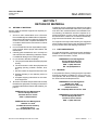
SECTION 1 DESCRIPTION AND SPECIFICATIONS ........................................................ 1 - 1
1-1 OVERVIEW ................................................................................................................ 1 - 1
1-2 TYPICAL APPLICATIONS .......................................................................................... 1 - 1
1-3 THEORY OF TECHNOLOGY ..................................................................................... 1 - 1
1-4 FEATURES ................................................................................................................. 1 - 1
1-5 SPECIFICATIONS ...................................................................................................... 1 - 5
a. General ................................................................................................................... 1 - 5
b. Physical .................................................................................................................. 1 - 5
c. Sample ................................................................................................................... 1 - 5
d. Gas Connections .................................................................................................... 1 - 5
Emerson Process Management GmbH & Co.OHG
Table of Contents
I
Instruction Manual
NGA 2000 CLD
HAS60E-IM-HW
June 2007
SECTION 2 INSTALLATION .............................................................................................. 2 - 1
2-1 UNPACKING ............................................................................................................... 2 - 1
2-2 ASSEMBLY ................................................................................................................. 2 - 1
2-3 LOCATION .................................................................................................................. 2 - 2
2-4 GASES ....................................................................................................................... 2 - 2
a. Gas Conditioning (Sample Handling) ..................................................................... 2 - 2
b. Connections ............................................................................................................ 2 - 3
c. Specifications ......................................................................................................... 2 - 3
Zero Gas ..............................................................................................................................2 - 3
Span Gas .............................................................................................................................2 - 3
Ozonator Source Gas ..........................................................................................................2 - 3
Sample Gas Pressure ..........................................................................................................2 - 3
Bypass Sample Gas Flow ....................................................................................................2 - 3
Leak Test ..............................................................................................................................2 - 4
Contaminants .......................................................................................................................2 - 4
2-5 ELECTRICAL CONNECTIONS .................................................................................. 2 - 4
SECTION 3 OPERATION .................................................................................................. 3 - 1
3-1 OVERVIEW ................................................................................................................ 3 - 1
3-2 STARTUP & INITIALIZATION ..................................................................................... 3 - 1
3-3 PREPARATIONS ........................................................................................................ 3 - 2
3-4 CALIBRATION PROCEDURE .................................................................................... 3 - 4
a. Calibration Setup .................................................................................................... 3 - 4
Calibration Gas List ..............................................................................................................3 - 4
Calibration Parameters ........................................................................................................3 - 5
b. Flow Balance Adjustment: ...................................................................................... 3 - 6
Zero Adjustment ...................................................................................................................3 - 6
Span Adjustment ..................................................................................................................3 - 6
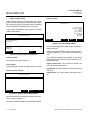
3-5 SYSTEM & NETWORK I/O MODULE CONTROLS (SETUP) - SYSTEM SIO .......... 3 - 8
a. Analog Output Setup .............................................................................................. 3 - 8
Output number: ....................................................................................................................3 - 8
Choose signal source module... ...........................................................................................3 - 8
Choose Signal... ...................................................................................................................3 - 8
Signal value for 0% (100%) output: .....................................................................................3 - 9
Output current: .....................................................................................................................3 - 9
Hold output during calibration: .............................................................................................3 - 9
b. Serial interface Setup ........................................................................................... 3 - 11
II
Table of Contents
Emerson Process Management GmbH & Co.OHG
Instruction Manual
HAS60E-IM-HW
June 2007
NGA 2000 CLD
c. Relay Outputs Setup ............................................................................................ 3 - 12
Output number: .................................................................................................................. 3 - 12
Invert signal: .......................................................................................................................3 - 12
Choose source module... ...................................................................................................3 - 12
Choose signal... .................................................................................................................3 - 12
3-6 CONVERTER TEMPERATURE ADJUSTMENT ...................................................... 3 - 13
3-7 MEASUREMENT OF CONVERTER EFFICIENCY .................................................. 3 - 14
a. Test Setup for Measurement of Conversion Efficiency ......................................... 3 - 14
b. Test Procedure ..................................................................................................... 3 - 14
c. Subnormal Conversion Efficiency ......................................................................... 3 - 15
d. Replacement of Converter .................................................................................... 3 - 16
e. Capillaries ............................................................................................................. 3 - 16
f. TEA Scrubber ....................................................................................................... 3 - 16
SECTION 4 MAINTENANCE AND SERVICE .................................................................... 4 - 1
4-1 OVERVIEW ................................................................................................................ 4 - 1
4-2 FUSES ........................................................................................................................ 4 - 2
4-3 FANS .......................................................................................................................... 4 - 2
4-4 OZONATOR ................................................................................................................ 4 - 2
4-5 PRINTED CIRCUIT BOARDS .................................................................................... 4 - 2
4-6 CONVERTER ............................................................................................................. 4 - 4
4-7 DETECTOR DISASSEMBLY ...................................................................................... 4 - 5
a. Reaction Chamber Removal .................................................................................. 4 - 5
b. Reaction Chamber Installation ............................................................................... 4 - 5
c. Photodiode Removal .............................................................................................. 4 - 5
d. Photodiode Installation ........................................................................................... 4 - 5
4-8 LEAKAGE TEST ......................................................................................................... 4 - 7
a) Required Tools ........................................................................................................ 4 - 7
b) Procedure ............................................................................................................... 4 - 7
SECTION 5 TROUBLESHOOTING ................................................................................... 5 - 1
5-1 OVERVIEW ................................................................................................................ 5 - 1
Emerson Process Management GmbH & Co.OHG
Table of Contents
III
Instruction Manual
NGA 2000 CLD
HAS60E-IM-HW
June 2007
SECTION 6 REPLACEMENT PARTS ............................................................................... 6 - 1
6-1 MATRIX ...................................................................................................................... 6 - 1
6-2 REPLACEMENT PARTS ............................................................................................ 6 - 2
SECTION 7 RETURN OF MATERIAL ............................................................................... 7 - 1
7-1 RETURN OF MATERIAL ............................................................................................ 7 - 1
7-2 CUSTOMER SERVICE ............................................................................................... 7 - 1
7-3 TRAINING ................................................................................................................... 7 - 1
LIST OF FIGURES AND TABLES ...................................................................................... L - 1
1
LIST OF FIGURES ..................................................................................................... L - 1
2
LIST OF TABLES ....................................................................................................... L - 2
IV
Table of Contents
Emerson Process Management GmbH & Co.OHG
Instruction Manual
HAS60E-IM-HW
June 2007
NGA 2000 CLD
PREFACE
The purpose of this manual is to provide information concerning the components, functions, installation and
maintenance of the NGA 2000 CLD and the System Accessories of the NGA 2000 System.
Some sections may describe equipment not used in your configuration. The user should become thoroughly
familiar with the operation of this module before operating it. Read this instruction manual completely.
DEFINITIONS
The following definitions apply to WARNINGS, CAUTIONS and NOTES found throughout this publication.
WARNING
Highlights on operation or maintenance procedure, practice, condition, statement, etc.
If not strictly observed, could result in injury, death, or long-term health hazards of personnel.
CAUTION
Highlights on operation or maintenance procedure, practice, condition, statement, etc.
If not strictly observed, could result in damage to or destruction of equipment, or loss of effectiveness.
NOTE
Highlights an essential operating procedure, condition or statement.
Emerson Process Management GmbH & Co.OHG
Preface
P-1
Instruction Manual
HAS60E-IM-HW
June 2007
NGA 2000 CLD
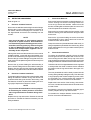
IMPORTANT
SAFETY INSTRUCTIONS
WIRING AND INSTALLATION OF THIS APPARATUS
The following safety instructions apply specifically to all EU member states. They should be strictly adhered to
in order to assure compliance with the Low Voltage Directive. Non-EU states should also comply with the
following unless superseded by local or National Standards.
1. Adequate earth connections should be made to all earthing points, internal and external, where provided.
2. After installation or troubleshooting, all safety covers and safety grounds must be replaced. The integrity
of all earth terminals must be maintained at all times.
3. To ensure safe operation of this equipment, connection to the mains supply should only be made through
a circuit breaker which will disconnect all circuits carrying conductors during a fault situation. The circuit
breaker may also include a mechanically operated isolating switch. Circuit breakers or switches must
comply with a recognized standard such as IEC947. All wiring must conform with any local standards.
4. Where equipment or covers are marked with the symbol to the right, hazardous voltages
are likely to be present beneath. These covers should only be removed when power is
removed from the equipment — and then by trained service personnel only.
5. Where equipment or covers are marked with the symbol to the right, there is a danger
from hot surfaces beneath. These covers should only be removed by trained service
personnel when power is removed from the equipment. Certain surfaces may remain
hot to the touch.
6. Where equipment or covers are marked with the symbol to the right, refer to the Instruction Manual for instructions.
7. Further graphical symbols used in this product:
Elektrostatic discharge (ESD)
Harmful (to Health)!
Explosion Hazard!
Toxic!
UV Source!
Disconnect from Mains!
All graphical symbols used in this product are from one or more of the following standards:
EN61010-1, IEC417, and ISO3864.
P-2
Preface
Emerson Process Management GmbH & Co.OHG
Instruction Manual
HAS60E-IM-HW
June 2007
NGA 2000 CLD
OPERATING AND MAINTAINING THIS APPARATUS
This instrument has left the factory in compliance with all applicable safety regulations.
To maintain this operating condition, the user must strictly follow the instructions and consider the warnings in
this manual or provided on the instrument.
Before switching on the instrument, verify that the electrical supply voltage matches the instrument´s operating voltage as set in the factory.
Any interruption in the instrument´s ground line, whether inside or outside the instrument, or removal or
interruption of its ground line connection, could result in hazardous operating conditions. Intentionally interrupting the instrument´s protective ground is strictly prohibited.
Opening cover panels could expose voltage-carrying components. Connectors may also be under voltage.
The instrument must be disconnected from all electrical supplies before attempting any calibrations, maintenance operations, repairs or component replacements requiring opening of the instrument. Any calibrations,
maintenance operations, or repairs that need the instrument to be opened while connected to electrical
supplies should be subject to qualified technicians familiar with the hazards involved only!
Use only fuses of the correct type and current ratings as replacements. Using repaired fuses and short
circuiting of fuse holders is prohibited.
Observe all applicable regulations when operating the instrument from an auto-transformer or variac.
Substances hazardous to health may emerge from the instrument‘s exhaust.
Please pay attention to the safety of your operation personnel. Protective measures must be taken, if required.
NOTE
Software compatibility is necessary for all NGA 2000 components in your system to work together.
The version of your Platform’s software must be equal to or greater than the version of any other
module(s) for successful compatibility.
You can locate the version of each NGA 2000 component as follows:
Platform Controller Board
Turn power ON. The display should show „Control Module V3. ...“. This is the software version.
Analyzer Module
See note on the name plate label located on the right side of the Analyzer Module case.
Emerson Process Management GmbH & Co.OHG
Preface
P-3
Instruction Manual
HAS60E-IM-HW
June 2007
NGA 2000 CLD
SAFETY SUMMARY
If this equipment is used in a manner not specified in these instructions, protective systems may be
impaired.
AUTHORIZED PERSONNEL
To avoid loss of life, personal injury and damage to this equipment and on-site property, do not
operate or service this instrument before reading and understanding this instruction manual and
receiving appropriate training. Save these instructions.
WARNING
ELECTRICAL SHOCK HAZARD !
Do not operate without covers secure. Do not open while energized. Installation and/or servicing
requires access to live parts which can cause death or serious injury.
Refer servicing to qualified personnel.
For safety and proper performace this instrument must be connected to a properly grounded threewire source of power.
WARNING
TOXIC AND OXIDIZING GAS
This module generates ozone which is toxic by inhalation and is a strong irritant to throat and
lungs. Ozone is also a strong oxidizing agent. Its presence is detected by a characteristic pungent
odor.
The module’s exhaust contains both ozone and nitrogen dioxide, both toxic by inhalation, and may
contain other constituents of the sample gas which may be toxic. Such gases include various
oxides of nitrogen, unburned hydrocarbons, carbon monoxide and other products of combustion
reactions. Carbon monoxide is highly toxic and can cause headache, nausea, loss of consciousness, and death.
Avoid inhalation of the ozone produced within the module, and avoid inhalation of the sample and
exhaust products transported within the module. Avoid inhalation of the combined exhaust products at the exhaust fitting.
Keep all tube fittings tight to avoid leaks. The user is responsible for leakage testing only at the inlet
and outlet fittings on the rear panel.
Connect rear exhaust outlet to outside vent with stainless steel or Teflon line. Check vent line and
connections for leakage.
P-4
Preface
Emerson Process Management GmbH & Co.OHG
Instruction Manual
HAS60E-IM-HW
June 2007
NGA 2000 CLD
WARNING
OVERBALANCE HAZARD
This analyzer module may tip instrument over if it is pulled out too far and the Platform is not
properly supported.
CAUTION
Tampering with or unauthorized substitution of components may adversely affect the safety of this
instrument. Use only factory documented/approved components for repair.
Because of the danger of introducing additional hazards, do not perform any unauthorized modification to this instrument!
WARNING
POSSIBLE EXPLOSION HAZARD
This equipment is not designed and should not be used in the analysis of flammable samples.
Use of this equipment in this way could result in explosion or death.
WARNING
POSSIBLE EXPLOSION HAZARD
Ensure that all gas connections are made as labeled and described within this manual and leak
free. Improper gas connections may cause explosion, serious injury or death.
CAUTION
HIGH TEMPERATURES !
While working at thermostated components inside the analyzer modules hot components may be
accessible!
CAUTION
Do not interchange gas inlets and outlet! All gases must be conditioned before supplying!
When supplying corrosive gases ensure that gas path components are not affected!
Exhaust lines must be installed in a descending way, need to be pressureless, frost-protected
and in compliance with applicable legislative requirements!
Emerson Process Management GmbH & Co.OHG
Preface
P-5
Instruction Manual
HAS60E-IM-HW
June 2007
NGA 2000 CLD
WARNING
Before opening gas paths they must be purged with ambient air or
neutral gas (N2) to avoid hazards caused by toxic, flammable, explosive
or harmful to health sample gas components!
WARNING
INTERNAL UV SOURCE !
Ultraviolet light from the ozone generator can cause permanent eye damage !
Do not look directly at the ultraviolet source !
Use of ultraviolet filtering glases is recommended.
WARNING
TOXIC CHEMICAL HAZARD!
The optional UV lamp contains mercury. Lamp breakage could result in mercury exposure !
Mercury is highly toxic if absorbed through the skin or ingested, or if vapors are inhaled.
Handle lamp assembly with extreme care. If the lamp is broken, avoid skin contact and inhalation in
the area of the lamp or the mercury spill.
Immediately clean up and dispose of the mercury spill and lamp residue as follows:
•
Wearing rubber gloves and goggles, collect all droplets of mercury by means of a suction
pump and aspirator bottle with a long capillary tube. (Alternately, a commercially available
mercury spill clean-up kit is recommended.)
•
Carefully sweep any remaining mercury and lamp debris into a dust pan. Carefully transfer all
mercury, lamp residue and debris into a platic bottle which cab be tightly capped.
•
Label and return to hazardous material reclamation center. Do not place in the trash, incinerate
or flush down the sewer.
•
Cover any fine droplets of mercury in non-accessible crevices with calcium polysulfide and
sulfur dust.
P-6
Preface
Emerson Process Management GmbH & Co.OHG
Instruction Manual
HAS60E-IM-HW
June 2007
NGA 2000 CLD
GASES AND GAS CONDITIONING (SAMPLE HANDLING)
WARNING
Take care of the safety instructions applicable for the gases
(sample gases, test gases and ozonator air)!
CAUTION
PRESSURIZED GAS
This module requires periodic use of pressurized gas. See General Precautions for Handling and
Storing High Pressure Gas Cylindes, page P-6.
CAUTION
EXTERNALLY RESTRICT SAMPLE FLOW TO LESS THAN 2,200 cc/min.
No restrictor is provided in the inlet of this module. For those users who cannot externally limit
sample flow, contact your local service or sales office.
POWER SUPPLY
CAUTION
Verify the power voltage at site of installation corresponds to the analyzer
module´s rated voltage as given on the nameplate label!
Verify the safety instruction given by power supply unit manufacturer !
CAUTION
The mains socket has to be nearby the power supply unit and easily accessible!
Disconnecting from power requires unplugging the power connector!
To comply with the CE mark requirements use only power supply units of type
SL10 or equivalent units. Equivalent units must provide SELV output voltages!
Verify proper polarity when connecting DC 24 V operated analyzer modules !
Emerson Process Management GmbH & Co.OHG
Preface
P-7
Instruction Manual
HAS60E-IM-HW
June 2007
NGA 2000 CLD
ELECTROSTATIC DISCHARGE
CAUTION
The electronic parts of the Analyzer Module can be irreparably damaged if
exposed to electrostatic discharge (ESD).
The instrument is ESD protected when the covers have been secured and safety
precautions observed. When the housing is open, the internal components are
not ESD protected anymore.
Although the electronic parts are reasonable safe to handle, you should be aware of the following considerations:
Best ESD example is when you walked across a carpet and then touched an electrical grounded metal
doorknob. The tiny spark which has jumped is the result of electrostatic discharge (ESD).
You prevent ESD by doing the following:
Remove the charge from your body before opening the housing and maintain during work with opened
housing, that no electrostatic charge can be built up.
Ideally you are opening the housing and working at an ESD - protecting workstation. Here you can wear a
wrist trap.
However, if you do not have such a workstation, be sure to do the following procedure exactly:
Discharge the electric charge from your body. Do this by touching a device that is grounded electrically
(any device that has a three - prong plug is grounded electrically when it is plugged into a power receptacle).
This should be done several times during the operation with opened housing (especially after leaving the
service site because the movement on a low conducting floors or in the air might cause additional ESDs).
P-8
Preface
Emerson Process Management GmbH & Co.OHG
Instruction Manual
HAS60E-IM-HW
June 2007
NGA 2000 CLD
GENERAL PRECAUTIONS FOR HANDLING AND STORING
HIGH PRESSURE GAS CYLINDERS
Edited from selected paragraphs of the Compressed Gas Association´s „Handbook of Compressed
Gases“ published in 1981.
Compressed Gas Association
1235 Jefferson Davis Highway
Arlington, Virginia 22202
Used by Permission
1. Never drop cylinders or permit them to strike each other violently.
2. Cylinders may be stored in the open, but in such cases, should be protected against extremes of weather
and, to prevent rusting, from the dampness of the ground. Cylinders should be stored in the shade when
located in areas where extreme temperatures are prevalent.
3. The valve protection cap should be left on each cylinder until it has been secured against a wall or bench,
or placed in a cylinder stand, and is ready to be used.
4. Avoid dragging, rolling, or sliding cylinders, even for a short distance; they should be moved by using a
suitable hand-truck.
5. Never tamper with safety devices in valves or cylinders.
6. Do not store full and empty cylinders together. Serious suckback can occur when an empty cylinder is
attached to a pressurized system.
7. No part of cylinder should be subjected to a temperature higher than 52 °C (125 °F). A flame should never
be permitted to come in contact with any part of a compressed gas cylinder.
8. Do not place cylinders where they may become part of an electric circuit. When electric arc welding,
precautions must be taken to prevent striking an arc against the cylinder.
Emerson Process Management GmbH & Co.OHG
Preface
P-9
Instruction Manual
HAS60E-IM-HW
June 2007
NGA 2000 CLD
DOCUMENTATION
The following CLD instruction materials are available. Contact Customer Service Center or the local representative to order.
HAS60E-IM-HW
Instruction Manual NGA 2000 CLD (this document)
HAS60E-IM-SW39
Software Manual NGA 2000 CLD
90002496
Instruction Manual NGA 2000 Platform
COMPLIANCES
This product may carry approvals from several certifying agencies, including the Canadian Standards Association (which
is also an OSHA accredited, Nationally Recognized Testing Laboratory), for use in non-hazardous, indoor locations.
Emerson Process Management has satisfied all obligations from the European Legislation to harmonize the product
requirements in Europe.
This product complies with the standard level of NAMUR EMC. Recommendation (May 1993).
NAMUR
This product satisfies all obligations of all relevant standards of the EMC framework in Australia and New Zealand.
N96
SUITABILITY TESTS
P - 10 Preface
Emerson Process Management GmbH & Co.OHG
Instruction Manual
HAS60E-IM-HW
June 2007
NGA 2000 CLD
GLOSSARY OF TERMS
Analyzer Module
The module that contains all sensor/detector components for development of a Primary Variable signal;
includes all signal conditioning and temperature control circuitry.
Backplane
The interconnect circuit board which the Controller Board, Power Supply, Analyzer Module power and network
cables, I/O Modules and Expansion Modules plug into.
Control Module
The Operator Interface plus the Controller Board.
Controller Board
The computer board that serves as the Network Manager and operate the Display and Keypad.
Distribution Assembly
The Backplane and the card cages that hold I/O and Expansion Modules.
I/O Module
A circuit board that plugs into the Backplane from the rear of the Platform. Has a connector terminal for
communication with external data acquisition devices and provides an input/output function.
Power Supply
Any of a variety of components that provides conditioned power to other NGA 2000 components, from the
Power Supply Board that plugs into the front of the Backplane in a stand-alone instrument to several larger
ones that can power larger collections of modules and components.
Emerson Process Management GmbH & Co.OHG
Preface P - 11
Instruction Manual
HAS60E-IM-HW
June 2007
NGA 2000 CLD
Primary Variable
The measured species concentration value from an Analyzer Module.
Secondary Variable
Data placed on the network by a module regarding current status, e.g., sample flow, temperature and pressure.
Softkeys
The five function softkeys located below the front panel display; they assume the function displayed directly
above each on the display, a function dictated by software.
System
Any collection of Analyzer Module(s), Platform(s) and I/O Module(s).
P - 12 Preface
Emerson Process Management GmbH & Co.OHG
Instruction Manual
HAS60E-IM-HW
June 2007
NGA 2000 CLD
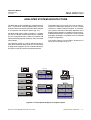
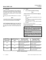
ANALYZER SYSTEM ARCHITECTURE
The platform/MLT´s front panel can act as operator interface for a stand-alone analyzer or as the a central
interface for multiple Analyzer Modules. In multi analyzer systems, this feature eliminates duplication of the
display/operator interface. In addition to the obvious operational benefits there are significant cost and system
packaging advantages not possible with conventional
analyser configurations.
The NGA 2000 CLD is available as a "stand-alone analyzer" or as a "blind" Analyzer Module (AM). The CLD
analyzer module can be part of the stand-alone analyzer
or a component of an analyzers system (Fig. A-1).
The NGA 2000 system made it possible, to configure
the CLD as a flexible "stand-alone analyzer" consisting
of a CLD "Analyzer Module", a Platform (complete with
front panel display/operator interface), and input/output
(I/O) modules.
This flexible network communication architecture is
shown in the schematic of Fig. A-2.
The “analyzer module” is a “blind” analysis unit but retains all the advanced design features. The AM variant
is designed for integration as part of a NGA 2000 analysis system or special customer developed networks.
½ 19" MLT
NGA Network
Analyzer
NGA 2000
NGA Network
ROSEMOUNT
Platform with MLT AM
or
19" MLT Analyzer
ROSEMOUNT
NGA 2000
ROSEMOUNT
NGA 2000
CLD
½ 19" MLT
Analyzer
ROSEMOUNT
FID
NGA 2000
NGA Network
PS
CLD
NGA 2000
Platform with MLT AM
or
19" MLT Analyzer
ROSEMOUNT
CLD
MLT
MLT
CLD
FID
NGA 2000
PS
NGA Network
ROSEMOUNT
NGA Network
FID
NGA Network
PMD
ROSEMOUNT
NGA 2000
PS
Figure A-1: From separate analyzers to analyzer system
Emerson Process Management GmbH & Co.OHG
Analyzer System Architecture
A-1
Instruction Manual
HAS60E-IM-HW
June 2007
NGA 2000 CLD
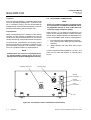
The modular configurable bi-directional network offers
the following options:
❏
❏
Stand-alone analyzers (Single devices)
• analyzer modules in a platform including
optional inputs and outputs (SIO/DIO).
Simple interconnection of analyzer modules to an
analyzer system based on one of the three structures - see below.
These structures can be distinguished by acting
of the host
• with platform as host including system inputs
and outputs (SIO/DIO)
• with MLT/TFID/CAT 200 analyzer as controller
including system inputs and outputs (SIO/DIO)
• with customer owned specific control units
(not described in this manual, consult factory)
For combination possibilities of NGA 2000 I/O´s see table
A-1.
Platform
Analyzer Module
Analyzer Module
AC
DC
Network Cable
Analyzer Module
Network Cable
Power supply
24VDC Cable
24VDC Cable
DC
AC
Figure A-2: Example of NGA cabling
A-2
Analyzer System Architecture
Emerson Process Management GmbH & Co.OHG
Instruction Manual
HAS60E-IM-HW
June 2007
NGA 2000 CLD
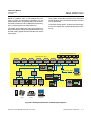
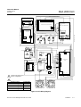
Based on a platform, MLT or TFID analyzer the schematic on Figure A-3 illustrates the simplicity of a networked system which incorporates AM’s, such as Chemiluminesence Detectors, MLT's (NDIR/UV/VIS plus Oxygen or TCD) and Flame Ionisation Detectors.
Other system functionality includes links to associated
sample handling (PLC) and Data Acquisition Systems
such as WinControl.
Local I/O are existing to MLT, TFID and CAT 200 analyzers only and support the corresponding analyzer module only.
The system I/O modules (SIO, DIO) of the platform (or
MLT/TFID analyzer) support all integrated analyzer modules with analog, digital and serial interfaces as well as
relay outputs.
Local I/Os via Internal System Bus
DIO
Analyzer Modules (AMs)
O2
PMD
HC
HFID
NO x
WCLD
NO/NO x
CLD
System I/Os via Internal System Bus
ppm O 2
TO2
HC
FID
HC
TFID
SIO
DIO
CO/NO/SO2 /
EO 2 - MLT
PO 2
MLT
Alternatively to Platform
or MLT/TFID Analyzer
19" Platform/
TFID Analyzer
Field PC
Workstation
ROSEMOUNT
8
Digital
Inputs
24
Digital
Outputs
3
Relay
Outputs
RS 232 /
RS 485
Printer
or PLC
NGA 2000
Alternatively
MLT 2
Analyzer
½ 19" MLT
Analyzer
ROSEMOUNT
Solenoid
Valves
SIO
NGA 2000
Alternatively
SIO
DIO
NGA
Network
19" MLT 3/4
Analyzer
ROSEMOUNT
DIO
SIO
ROSEMOUNT
NGA 2000
NGA 2000
Personal
Computer
Figure A-3: Example/Possibilities of NGA Analyzer Systems
Emerson Process Management GmbH & Co.OHG
Analyzer System Architecture
A-3
Instruction Manual
HAS60E-IM-HW
June 2007
NGA 2000 CLD
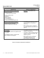
System unit
CLD/FID/HFID analyzer module (AM):
• without front panel,
i.e. without control unit (host)
•
•
No local CLD/FID/HFID I/O’s
•
1 SIO and up to 4 DIO's (or 5 DIO's)
can be installed in the platform
(CM I/O’s)
•
SIO and DIO’s can be configured
for all AM channels connected to the
platform
•
1 SIO and 4 DIO’s (or 5 DIO’s) can be
installed in the platform
•
1 SIO and 1 DIO (or 2 DIO’s) can be
installed in the MLT/TFID/CAT 200
analyzer (CM I/O)
•
SIO and DIO can be configured
for all AM’s connected to the
MLT/TFID/CAT 200 analyzer
can be combined with
a platform,
a MLT analyzer,
a TFID analyzer;
a CAT 200 analyzer or
a customer developed control unit
Platform (Control Module Software):
• Control unit with front panel
• Without measurement channels
CLD analyzer
• CLD analyzer module into a platform with
front panel
•
SIO/DIO-Configuration
CLD analyzer module combined with
MLT/TFID/CAT 200 analyzer
Table A-1: Possibilities of NGA 2000 I/O combinations
A-4
Analyzer System Architecture
Emerson Process Management GmbH & Co.OHG
Instruction Manual
HAS60E-IM-HW
June 2007
NGA 2000 CLD
SECTION 1
DESCRIPTION AND SPECIFICATIONS
1-1
OVERVIEW
The reactions involved are:
This manual describes the Chemiluminescence (CLD)
Analyzer Module of Emerson Process Mangement´s
NGA 2000 Series of gas analysis components (See Figure 1-2, Figure 1-3 and Figure 1-4).
The CLD Analyzer Module is designed to continously
determine the concentration of Nitric Oxide and oxides
of Nitrogen (NO plus Nitrogen Dioxide [NO2]) in a flowing gaseous mixture. The concentration is expressed in
parts-per-million.
The CLD Analyzer Module is designed as a slide-in
module (if configured in stand-alone instrument fashion),
removable from the front of the Platform, with gas connections made from the rear. All electronics relative to
sample detection and conditioning are included in this
module.
1-2
TYPICAL APPLICATIONS
The CLD Analyzer Module has specific applications in
the following areas:
•
•
•
•
1-3
Oxides of Nitrogen emissions from the combustion of fossil fuels in
Vehicle engine exhaust
Incinerators
Boilers
Gas appliances
Turbine exhaust
Nitric acid plant emissions
De-NOx control system
Nitric oxide emissions from decaying organic
material (e.g., landfills).
THEORY OF TECHNOLOGY
The CLD Analyzer Module uses the chemiluminescence
method of detection. This technology is based on the
reaction of NO with ozone (O3) to produce NO2 and oxygen (O2). Some of the NO2 molecules thus produced
are in an electronically excited state (NO2* - the "*“ refers
to the excitation). These revert immediately to the ground
state, with emission of photons (essentially, red light).
Emerson Process Management GmbH & Co.OHG
NO + O3
→ NO2* + O2
NO2* → NO2 + red light
As NO and O3 mix in the reaction chamber, the intensity
of the emitted red light is measured by a photodiode and
is proportional to the concentration of NO in the original
gas sample.
To measure NOx (NO + NO2), any NO2 in the sample is
reduced to NO (at < 95 % efficiency) by being continously
passed through a heated bed of vitreous carbon (this
occurs before the sample gas is presented to the ozone).
Any NO initially present in the sample passes through
this converter stage unchanged before being routed to
the reaction chamber.
The photodiode generates a DC current, which is then
amplified, conditioned and expressed on the network as
the Primary Variable.
Exhaust
NO Molecule
O 2 Molecule
NO
Ozone
O 3 Molecule
NO 2 Molecule
(excitated)
NO 2 Molecule
Figure 1-1: Function Principle of
CLD Measurement
1-4
FEATURES
Among the features included in the CLD Analyzer Module are:
•
•
1) ozonator air loss shutoff and
2) NO/NOx mode capability.
Description and Specifications
1-1
Instruction Manual
HAS60E-IM-HW
June 2007
NGA 2000 CLD
Air Restrictor
430 cc/min. @ 12 psig
658157
Connector
1/8T - 1/8NPT BRS
Bulkhead Reducer
1/4T-1/8T SS
Male Connector
1/8T - 3/8NPT BRS
Ozone Air
Cross
1/8T BRS
Male Connector
1/8T - 3/8NPT BRS
0.116 ID Viton BLK
Pressure Switch
655215
Connector Glass
Pressure Sensor
BLUE
30 psig Air
655254
Elbow
1/8T - 1/8MPT KYNAR
Flow Balance
Valve
903207
Tee Assembly
1/8T - 1/4MPT
(see Table 1-1)
Bulkhead Reducer
1/4T - 1/8T SS
Tee
1/4T-1/8FPT SS
Bulkhead
1/4T SS
Connector
1/4T SS
NOx to NO
Converter
655250
Top
Tee 1/8T
KYNAR
Bypass
Flow Sensor
902931
Back
Pressure
Regulator
Sample
Exhaust
Ozone Generator
657719
Elbow
1/8T - 1/8MPT
KYNAR
Cross
1/8T SS
Elbow
1/8T - 1/4MPT
SS
Vent Capillary
70 cc/min. 5 psig
634398
Elbow
1/8T SS
1/8 OD SS
Elbow
1/8T SS
Pump Capillary
Tee
1/8 OD TEFLON
1/8T
(see Table 1-1) KYNAR
1/8 OD SS
Reaction Chamber
Ozone
Exhaust
Sample
Tee 1/8T
KYNAR
Reducer
1/4T - 1/8T SS
Connector Glass
BLUE
Sample Pressure Sensor
15 psig
655253
Male Connector
1/8T - 3/8NPT SS
Reduction Union
1/8T - 1/16T SS
Sample Capillary
(see Table 1-1)
Elbow
1/8T - 1/4MPT SS
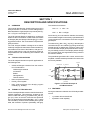
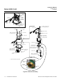
Figure 1-2: Flow Diagram - CLD Analyzer Module with Bypass Flow Sensor
Brief Description
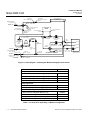
Part Number
Sample Capillaries
Sample Capillary 200 cc/min. @ 5 psig
659658
Sample Capillary 200 cc/min. @ 2 psig
660404
Sample Capillary 70 cc/min. @ 5 psig
659657
Sample Capillary 70 cc/min. @ 2 psig
660403
Pump Capillaries
Pump Capillary 200 cc/min. @ 5 psig
657473
Pump Capillary 200 cc/min. @ 2 psig
660405
Back Pressure Regulators
Back Pressure Regulator Brass 5 psig
655269
Back Pressure Regulator Stainless Steel 5 psig
659063
Back Pressure Regulator Brass 2 psig
660400
Back Pressure Regulator Stainless Steel 2 psig
660401
Table 1-1: Components depending on Module Configuration
1-2
Description and Specifications
Emerson Process Management GmbH & Co.OHG
Instruction Manual
HAS60E-IM-HW
June 2007
NGA 2000 CLD
Connector
1/8T - 1/8NPT BRS
Bulkhead Reducer
1/4T-1/8T SS
Air Restrictor
430 cc/min. @ 12 psig
658157
Ozone Generator
657719
Male Connector
1/8T - 3/8NPT BRS
Ozone Air
Cross
1/8T BRS
Male Connector
1/8T - 3/8NPT BRS
0.116 ID Viton BLK
Pressure Switch
655215
Connector Glass
Pressure Sensor
BLUE
30 psig Air
655254
NOx to NO
Converter
655250
Top
Tee 1/8T
KYNAR
Flow Balance
Valve
903207
Tee Assembly
1/8T - 1/4MPT
Vent Capillary
70 cc/min. 5 psig
634398
Tee
1/8T
KYNAR
Reaction Chamber
Union 1/8T SS
Ozone
Back
Pressure
Regulator
1/8 OD SS
Cross
1/8T SS
(see Table 1-1)
Elbow
1/8T - 1/4MPT
SS
Sample
Connector Glass
BLUE
Bulkhead Reducer
1/4T - 1/8T SS
Tee 1/8T
KYNAR
Exhaust
Bulkhead
1/4T SS
Union 1/8T SS
Pump Capillary
1/8 OD TEFLON
(see Table 1-1)
Exhaust
1/8 OD SS
Sample
Reduction Union
1/8T - 1/16T SS
Sample Pressure Sensor
15 psig
655253
Male Connector
1/8T - 3/8NPT SS
Sample Capillary
(see Table 1-1)
Tee 1/8T
KYNAR
Figure 1-3: Flow Diagram - CLD Analyzer Module without Bypass Flow Sensor
Emerson Process Management GmbH & Co.OHG
Description and Specifications
1-3
Instruction Manual
HAS60E-IM-HW
June 2007
NGA 2000 CLD
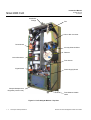
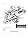
Inlet/Outlet
Fittings
Fan
NO2 to NO Converter
Driver Board
3/2-way Solenoid Valve
Detector
Ozone Generator
Flow Sensor
Signal Board
Power Supply Board
Sample Backpressure
Regulator (under Cover)
Flow Balance Needle
Valve
Figure 1-4: CLD Analyzer Module - Top View
1-4
Description and Specifications
Emerson Process Management GmbH & Co.OHG
Instruction Manual
HAS60E-IM-HW
June 2007
NGA 2000 CLD
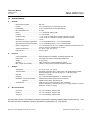
1-5
SPECIFICATIONS
a.
General
Measurement Species: ........................ NO, NOx
Ranges: .............................................. 0 to 5 ppm through 0 to 10,000 ppm NO, NOx
Repeatability: ...................................... ± 0.5 % of fullscale (at constant temperature)
Min. Detectable Level: ......................... 0.1 ppm
Noise: .................................................. < 1 % of fullscale, peak to peak
Linearity: ............................................. ± 1 % of fullscale
Response Time: .................................. < 1 sec. for 90 % of fullscale for ranges of 25 ppm or greater
< 3 sec. for 90 % of fullscale for ranges of less than 25 ppm
t90 Response ...................................... 1-2 sec.
Zero Drift: (at constant temperature) .... <± 1 % of fullscale/24 hours, <± 2 % of fullscale/week
Span Drift: (at constant temperature) ... <± 1 % of fullscale/24 hours, <± 3 % of fullscale/week
Effect of Temperature: ......................... < 2 % of fullscale (over any 10 °C ambient temperature variation interval for
a rate of change no greater than 10 °C/hour)
Ambient Temperature: ......................... 0 °C to 45 °C (32 °F to 113 °F)
Rated Power: ...................................... 24V DC 150W
b.
Physical
Case Classification: ............................. General purpose for installation in weather-protected area
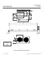
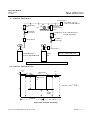
Dimensions: ........................................ See Figure 2-5: Outline and Mounting Dimensions
Weight: ................................................ 8.1 kg (18 lbs.)
Mounting: ............................................ Inside a Platform or custom-installed in a panel
Max. Length of LON Cable: ................. 1,600m (1 mile) between Analyzer Module and Platform
c.
Sample
Temperature: ....................................... 0 °C to 45 °C (32 °F to 131 °F)
Total Flow Rate: ................................... (Externally measured) 900 to 2,200 cc/min. with backpressure regulator
pressure adjusted to 1,344 hPa (5 psig) or to 1,138 hPa (2 psig)
Particles: ............................................. Filtered to < 2 microns
Dewpoint: ............................................ 5.5 °C below ambient temperature, no entrained liquid
Materials in contact with Sample: ........ Stainless steel, Teflon, glass, brass and neoprene
Optional: ............................ Stainless steel, Teflon, glass and Kynar
Ozonator Gas: ..................................... Clean, dry air or oxygen; flow rate: 1 l/min. maximum;
pressure: 689 hPa to 1,034 hPa-gauge (10 to 15 psig); maintain a constant
pressure ± 34 hPa (± 0.5 psig)
d.
Gas Connections
Ozone Air: ........................................... 1/4" O.D. tube fitting, stainless steel
Exhaust: .............................................. 1/4" O.D. tube fitting, stainless steel
Sample In: ........................................... 1/4" O.D. tube fitting, stainless steel
See the Preface section of the Platform manual for specifications regarding Platform-related components (e.g., case
dimensions) and the I/O Module manual for specifications regarding I/O (e.g., relay outputs).
Emerson Process Management GmbH & Co.OHG
Description and Specifications
1-5
Instruction Manual
NGA 2000 CLD
1-6
Description and Specifications
HAS60E-IM-HW
June 2007
Emerson Process Management GmbH & Co.OHG
Instruction Manual
HAS60E-IM-HW
June 2007
NGA 2000 CLD
SECTION 2
INSTALLATION
2-2
WARNING
Before starting to install this equipment, read the
"Essential instructions" on the inside cover and
the Safety Summary beginning on page P-2.
Failure to follow the safety instructions could result in serious injury or death.
2-1
If the CLD Analyzer Module requires assembly with other
components (e.g., the Platform and associated I/O Modules), do so at this time.
To install the CLD Analyzer Module into a Platform:
1.
2.
UNPACKING
If the Chemiluminescence (CLD) Analyzer Module is
received as a separate unit, carefully examine the shipping carton and contents for signs of damage. Immediately notify the shipping carrier if the carton or contents
is damaged. Retain the carton and packing material until all components associated with the CLD Analyzer
Module are operational.
ASSEMBLY
3.
4.
5.
6.
Loosen the six fastening screws for the front panel
of the Platform, hold the handles, and swing the
front panel to the farest right.
Following the guides on the bottom left and bottom center of the Platform, carefully slide the CLD
Analyzer Module halfway into place
Lift the spring-loaded pins on the front of the CLD
Analyzer Module, and carefully slide in the rest of
the distance.
If the module and Platform are difficult to assemble,
remove the module, ensure the top cover of the
module is firmly seated on the hold-down screws,
and repeat the assembly procedure.
Secure the module in position by releasing the pins,
which seat in the available holes in the bottom of
the case (see Figure 2-1, below).
Connect network cable and power cable to the
Analyzer Module (refer to Section 2-5 for electrical
connections).
After startup and calibration have been performed,
secure the front panel of the Platform with the six
screws provided.
Pin Seats
Analyzer Module Guides
Figure 2-1: Analyzer Module Installation into Instrument Platform (view without front panel)
Emerson Process Management GmbH & Co.OHG
Installation
2-1
Instruction Manual
HAS60E-IM-HW
June 2007
NGA 2000 CLD
2-4
GASES
Install the CLD Analyzer Module in a clean, weather-protected, vibration-free location free from extreme temperature variations and moisture. For best results, install the
instrument near the sample stream to minimize sample
transport time.
a.
Gas Conditioning (Sample Handling)
The analyzer should be installed within ±15° of horizontal.
The gases must be
dry
free of dust (filtered for particulates down to two
microns)
free of aggressive components affecting gas paths
materials (e.g. by corrosion)
free of Ammonia etc. in order to prevent crystallin
formation
before entering the Analyzer Module.
2-3
LOCATION
NOTE
Unrestricted air flow to the rear of the Analyzer Module is critical to its performance and reliablilty.
Operating ambient temperature is 0 °C to 45 °C (32 °F to
113 °F). Temperature change should not exceed 10 °C
(18 °F) per hour. The same temperature range restrictions apply to the location of the air and span gas cylinders.
NOTE
All gases must be conditioned before supplying!
The gases should have a dew point 5 °C (13 °F) below
coldest ambient temperature.
CAUTION
EXTERNALLY RESTRICT SAMPLE/CALIBRATION
GAS FLOW TO LESS THAN 2,200 cc/min.
Damage to internal components may occur if this
flow level is exceeded.
No restrictor is provided in the sample inlet of this
module. For those users who cannot externally
limit sample flow, contact your local service or
sales office.
MAXIMUM NOx
LEVEL IN PARTS
PER MILLION
GAS SUPPLIED TO
REAR PANEL AIR
INLET
800
Air
690 hPa (10 psig); provides flow
of approximately 500 cc/min. to
ozone generator
344 hPa (5 psig); provides flow
of approximately 200 cc/min. to
reaction chamber
2,500
Air
690 hPa (10 psig); provides flow
of approximately 1,000 cc/min. to
ozone generator.
344 hPa (5 psig); provides flow
of approximately 70 cc/min. to
reaction chamber.
10,000
Oxygen
1035 hPa (15 psig); provides flow
of approximately 1,000 cc/min to
ozone generator.
103 hPa (1.5 psig); procides
flow of approximately 20 cc/min.
to reaction chamber.
SETTING ON OZONE
PRESSURE GAUGE
(pressure values: gauge)
SETTING ON SAMPLE
PRESSURE GAUGE
(pressure values: gauge)
Table 2-1: Gas Specifications
2-2
Installation
Emerson Process Management GmbH & Co.OHG
Instruction Manual
HAS60E-IM-HW
June 2007
NGA 2000 CLD
Exhaust
Exhaust Fan
Sample IN
Ozonator Air
Intake Fan
Figure 2-2: CLD Rear Panel Connections
b.
Connections
Connect inlet and outlet lines for sample, ozonator air,
and exhaust to appropriately labeled fittings on the rear
panel (see Figure 2-2) , each of which is a 1/4-inch ferrule-type compression fitting.
Stainless steel or Teflon tubing is recommended for the
sample line. Exhaust tubing should be 1/4 inch (6.3 mm)
or larger, and made of stainless steel or Teflon.
Zero/span gases should be introduced at the SAMPLE
IN fitting at normal sample inlet flow rate/pressure.
c.
Specifications
Each gas should be supplied from a cylinder equipped
with a clean, non-corrosive, two-stage regulator. A shutoff valve is recommended.
Ozonator Source Gas
For analyzers with ranges less than 0 to 2,500 ppm NOx
free ambient air should be used for generation of the
ozone required for the chemiluminescence reaction. For
ranges higher than 0 to 2,500 ppm, NOx free oxygen is
required. See Table 2-1 for correct pressure settings.
When using ambient air an external air conditioning unit
(LAM) can optionally be used (contact your local service
or sales office).
CAUTION
At no time should ozonator gas pressure exceed
2,070 hPa-gauge (30 psig). Damage to internal components may occur if this pressure level is exceeded.
Zero Gas
Sample Gas Pressure
Nitrogen (N2) is recommended for use as zero gas.
Alternatively synthetic air or NOx free ambient air can be
used.
See Table 2-1 for correct pressure settings.
Calibration Gas
A mixture of NO in a background of nitrogen is recommended as span gas. For maximum accurancy, the concentration of NO in the span gas should be about 80 %
to 100 % of full scale range.
Emerson Process Management GmbH & Co.OHG
Bypass Sample Gas Flow
Bypass sample gas flow rate should be between 700
and 2,000 cc/min. with backpressure regulator pressure
(see Capillary Pressure in „Current Measurement Parameters“ menu, which can be viewed by selecting the
PARMS softkey in "Main Menu") adjusted to 344 hPa (5
psig).
Installation
2-3
Instruction Manual
HAS60E-IM-HW
June 2007
NGA 2000 CLD
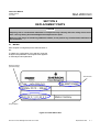
2-5
Leak Test
The CLD Analyzer Module is completely tested at the
factory for gas leakage (leakage rate - 7.5 hPa/min. with
He or - 2.5 hPa/min. with N2). The user is responsible for
leakage testing at the inlet and outlet fittings on the rear
panel minimum twice a year (see Section 4-8).
Contaminants
White crystal deposits on the windows of the reaction
chamber, and the clogging of capillaries and vent are
usually due to sample contaminates such as ammonia
reacting with the high ozone levels and NO components.
To eliminate the contaminates, the sampling system
should be reworked or a preventive maintenance program developed (if dropout is not excessive). Another
source of crystalline formation is contaminated air.
NOTE
Contamination is a result of a not properly working sample handling systrem and is not be covered by Emerson Process Management warranty.
Regulator Adjust Slot
ELECTRICAL CONNECTIONS
NOTE
Electrical installation must be in compliance with
the requirements of NAMUR and DIN VDE and/or
any applicable national or local codes (like local
electricity supply enterprises (ESE)).
Refer to figure 2-3. Two electrical connections are required on the Analyzer Module: POWER and NETWORK. On the Analyzer Module, two NETWORK connectors are available, either of which is appropriate for:
1.
2.
Interconnection with the Backplane of the Platform. (See Instruction Manual for the NGA 2000
Platform).
"Daisy-chaining" with other NGA 2000 components.
Connect Analyzer Module POWER to a 24 VDC, 10 A
power source, either the Platform or external power
source.
Metering Valve
FLOW
SAMPLE
BALANCE
LON
1
LON
2
Polarity
1+
24 V 2 3 GND
REGULATOR
Network
Connection “1”
Network
Connection “2”
Power
Connection
T 6A
~
250 V
Fuse
Figure 2-3: Front Panel Controls and Electrical Connections
2-4
Installation
Emerson Process Management GmbH & Co.OHG
Instruction Manual
HAS60E-IM-HW
June 2007
NGA 2000 CLD
HARNESS, EXPANSION I/O 655249
NC
POW ER SUPPLY BOARD-LON/POWER
MODULE ASSEMBLY 657510
1
J2
J1
LON/PWR MODULE
656761
1
J4
1
1
J5
J6
1
E3
E2
J5 3 2 1
E1
COMPUTER ANALYSIS BOARD 658350
J3
1
2
3
BLK
NC
1
1 2
WHT
POW ER SUPPLY
BOARD 657520
2
J1
J13 1 2 3 4 5 6 7 8 9
HARNESS, SIGNAL POWER 655252
WHT
BLK
GRN
SHLD*
BLU
YEL
ORN
WIRE*
BRN
8
2
J11
J3
J7 8 7 6
1 4 5 6 1 2 3 6
1
J2
BLK
WHT
GRN
RED
1
10
J11
J4
BLK
WHT
GRN
RED
FLOW
SENSOR
902931
RED
SAMPLE
PRESSURE
SENSOR
655254
CABLE, DIGITAL I/O 655246
2
3
SAMPLE
PRESSURE
SENSOR
655253
BLK
J2 1
3
12
PRESSURE
SWITCH (NO)
4-15 PSIG
655215
BLK
GRN
ORN
BLK
WHT
RED
10
1
*COAX CABLE
CABLE, FLOW SENSOR 655384
J1
9
J9
CABLE, INTERNAL NETWORK 903035-V1
J6
J13
7
1
SIGNAL BOARD 655580
5
4
3 J8
2
1
CABLE, ANALOG I/O 903033
J6
RED
J7
1
CABLE, CONTROLLER PWR 903034-V1
J5
J3
J2
BLK
GRN
ORN
GRN
RED
J1
J3
6
WHT BLK
BRN (NO)
12
1
YEL (COM)
7
HARNESS, DRIVER POW ER 655243
WHT
RED
4 3 1
NO/NOx
SOLENOID
655263
GRN
SHLD
WHT
WHT
CONVERTER HEATER JACKET 655228
CONVERTER TEMPERATURE
SENSOR 655282
JUMPER
657162
OZONATOR
POW ER
SUPPLY
657716
BLK 4
3
2
RED2
11
J2
BLK 4
33
2
RED 1
J1
WHT 2 1
WHT
J4
BRN 2 1
BRN
4
ORN 3
J9
2
ORN 1
J3
WHT
OZONATOR
657719
BLU
RED
YEL
CONVERTER
655250
SHIELD
1
J10
RED
THERMOSTAT
657298
CABLE, DIAGNOSTICS 903032-V1
WHT
RED
WHT
RED
2
THERMISTOR 655216
THERMOSTAT
DETECTOR
PHOTODIODE SOCKET ASSEMBLY 655218-V1
HEATERS
HEATER/THERMOSTAT ASSEMBLY 655235
TRANSISTOR
E
2SD1308
C
655264
B
1
2
3
4
5
6
7
8
B = YEL
C = RED
E = BLU
J8
5
4
3
2
1
4
3
BRN 2
1
YEL
DRIVER BOARD
655620
J5
J12
3
12
J11
1
10
1
2
J2 10 2
J6
24
Optional with Bypass Flow
Sensor Configuration
2
FAN 655245
Brief Description
FAN 655245
Part Number
Detector 200 cc/min. @ 5 psig
659754
Detector 200 cc/min. @ 2 psig
42716203
Detector 70 cc/min. @ 5 psig
42716204
Detector 70 cc/min. @ 2 psig
42716205
Figure 2-4: CLD Wiring Diagram
Emerson Process Management GmbH & Co.OHG
Installation
2-5
Instruction Manual
HAS60E-IM-HW
June 2007
NGA 2000 CLD
8.4
[213]
4.1
[104]
2.5
[64]
6.1
[155]
8.2
[208]
.4
[10]
.7
[18]
.8
[20]
1.5
[38]
4.3
[109]
2.8
[71]
1.1
[28]
6.0
[152]
17.5
[445]
.5
1.3
[33]
[13]
4.1
[104]
.9
[23]
.9
[23]
Dimensions:
1.3
[33]
INCHES
[MM]
Figure 2-5: Outline and Mounting Dimensions
2-6
Installation
Emerson Process Management GmbH & Co.OHG
Instruction Manual
HAS60E-IM-HW
June 2007
NGA 2000 CLD
SECTION 3
OPERATION
3-1
OVERVIEW
Once the CLD has been correctly assembled and installed, the analyzer is ready for operation.
Before operating the system, verify that the Leak Checks
have been performed in accordance with Section 2-4.
In this section, all operations for starting up the analyzer
are explained. For more detailed information about software screens see associated Software Manual.
For the remainder of this section, Analyzer Module interconnection with a Platform or some interfacing component is assumed. Display and Keypad information refers
to that which the user can expect to see and do with
regard to the Front Panel of the Platform.
Depending from the software version that is installed,
menu layout can change, whereas the principle of operation always stays the same.
This instruction manual is based on menus of software
version 3.7.1.
3-2
STARTUP & INITIALIZATION
the startup sequence will interrogate the network to locate and identify all components on the network. The
user will have to bind appropriate combinations of components after the startup sequence. See the Platform
manual for instructions on binding combinations of modules.
Pressing the F1 key during initializing will reset the CLD
brightness and contrast to factory settings. Pressing the
F3 softkey will abort the network initializing, aborting any
connection to other analyzers. In that case, only the
menus of the local analyzer will be available.
At the end of the initializing routine the "measure" screen
will display. This screen is the access to all other channels, menus and submenus. The actual display may differ from that shown depending on any custom configuration.
After the warm-up period (about one hour for the CLD
Analyzer Module), all modules are completely functional.
Establish that correct ozonator air pressure and sample
flow rate are within specifications (see Section 1-5). Calibrate and adjust converter efficiency, and begin operation as the following sections indicate.
Apply LON connection and power to the CLD Analyzer
Module. If it is associated with a Platform, do this by
plugging in the Platform to a power source. The Platform has no ON/OFF power button. Once power has
been supplied to the Platform, the CLD Analyzer Module
will be energized.
After switching on the CLD, the analyzer will begin its
booting procedure which is apparent on the CLD screen.
The first part of the initialization procedure is a self check
of the software and analyzer components. Various displays will show the status of the initialization including
revision notes, "Initializing network interface", "Searching for nodes", "Scanning Module 2: CLD, 12 % Complete", and "Calculating bindings".
If the user´s system contains only one Analyzer Module,
all system components, the Controller Board and the
network "self-install" (bind together) during initial startup.
If the system contains more than one Analyzer Module,
Emerson Process Management GmbH & Co.OHG
Operation
3-1
Instruction Manual
HAS60E-IM-HW
June 2007
NGA 2000 CLD
3-3
PREPARATIONS
After performing start-up and initialization that is described
in Section 3-2, operating variables must be adjusted, i.e.
the Analyzer Module is to be calibrated.
In the following, analyzer function control and calibration
procedure is described step-by-step.
CLD
7.50
ppm NO
0.00
Range 1
10.00
Sample Flow:
1300 ml/min 200
Sample press:
4.0 hPa 50.0
Ozonator: OFF-PRESS. SW.
Converter temp:
30.9 C 150.0
Display
Status...
Main...
Channel
BasicCal
0.000 ppm
0.7 hPa
4.0 hPa
OFF - PRES. SW.
Enabled
2 ml/min
320 C
51.5 C
1.1 C
51.5 C
199.9 ml/min
HISTORY
As long as operating temperatures are not yet
reached by the internal components of the analyzer, it is not ready for operation. Warm-up can
last up to one hour.
After warm-up or during warm-up procedure of the analyzer you can connect all gas supply lines to the back of
the analyzer.
Supply gases at the pressures given in the Test Data
Sheet and restrict flow by an external flow limiter to 1.3
through 1.5 l/min.
Internal sample gas and ozonator pressures:
You will find internal physical paramters in the Test
Data Sheet that you have received with the analyzer. Externally supply gases at the given pressures with an external adjustment.
Option Bypass Flow:
Main (Menu)...
Expert Controls and Setup...
Analyzer Module Setup...
Physical Measurements...
MORE
Block Temperature
Detector Temperature
Converter Temperature
NOTE:
Enter the diagnostics menu "Physical Measurements"
as follows, using the softkeys F1 through F5:
ESCAPE
•
•
•
500.0
To now check back physical parameters of the CLD Analyzer Module with the values defined in your Test Data
Sheet, that you received with the analyzer, you have to
select the "Physical Measurements"-Menu.
HOME
After warm up, check
with the operating values given by yout Test Data Sheet.
You will find an excerpt of a Test Data Sheet as an example on the next page in figure 3-3.
After starting up the Analyzer Module, the Measure Mode
Display is displayed as shown in figure 3-1.
Physical Measurements
Sample Capillary Pressure:
Ozone Supply Pressure:
Ozonator Status:
Ozonator Power:
Bypass Flow:
Converter temperature:
Ozonator temperature:
Sensor temperature:
Block temperature:
Capillary Flow Rate:
Pressure limits...
During warm-up time of the analyzer, you can observe
temperature values (sensor temperature, block temperature...) of internal components.
1500
490.0
Figure 3-1: Measure Mode Display
Line#1
The menu "Physical Measurements" lets you monitor
physical measurement parameters of the CLD analyzer.
Depending on measuring capillary, bypass flow
should by 900 - 2,000 cc/min. If no bypass is installed, restrict flow externally to 1.3 - 1.5 l/min.
INFO
Figure 3-2: Physical Measurements Display
3-2
Operation
Emerson Process Management GmbH & Co.OHG
Instruction Manual
HAS60E-IM-HW
June 2007
NGA 2000 CLD
Figure 3-3: Excerpt of a Test Data Sheet with values that are to be compaired with physical measurements.
Emerson Process Management GmbH & Co.OHG
Operation
3-3
Instruction Manual
HAS60E-IM-HW
June 2007
NGA 2000 CLD
3-4
MORE...
CALIBRATION PROCEDURE
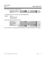
The CLD analyzer module may require periodic calibration with known zero and span gases in order to maintain a desire level of analytical accurancy. It is recommended, after initial startup, that the CLD Analyzer Module is calibrated at least once every eight hours.
This practice should continue until evidence indicates
that some other interval is more appropriate depending
on the analytical accurancy required.
Calibration is the process of flowing known zero or span
calibration gas into the analyzer for a specified period
(averaging time), after which the analyzer will automatically set its zero or span factors so that the concentration measurement equals the calibration gas value. A
limit can be set, beyond which any attempt by the analyzer to reset its concentration measurement will cause
a warning alarm. In this case, user intervention would be
required to reset the alarm and attempt another calibration.
a.
Calibration Setup
Calibration Gas List
This menu is used to set the concentration values of the
calibration gases for each range.
Main (Menu)...
Analyzer and I/O expert controls & setup...
Analyzer module setup...
Calibration gas list...
Line#1
0.000 ppm
Calibration Gas List
Zero gas - range 1:
NO Span gas - range 1:
NOx Span gas - range 1:
0.00 ppm
10.00 ppm
10.00 ppm
Zero gas - range 2:
NO Span gas - range 2:
NOx Span gas - range 2:
0.00 ppm
19.90 ppm
19.90 ppm
ESCAPE
MORE
Figure 3-4: Calibration Gas List
Channels 1 and 2
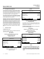
3-4
0.000 ppm
Calibration Gas List
Zero gas - range 3:
NO Span gas - range 3:
NOx Span gas - range 3:
0.00 ppm
101.0 ppm
101.0 ppm
Zero gas - range 4:
NO Span gas - range 4:
NOx Span gas - range 4:
0.00 ppm
250.0 ppm
250.0 ppm
Calibration...
HOME
ESCAPE
MORE
INFO
Figure 3-5: Calibration Gas List
Channels 3 and 4
If not yet done, put in the ozonator and zero gas concentrations that you supply to the analyzer. See gas cylinder
certification for exact values.
In case that measuring ranges differ from ordering code,
put in the measuring ranges:
Main (Menu)...
Analyzer and I/O, expert controls & setup...
Analyzer module setup...
Gas measurement parameters...
Range settings...
0.000 ppm
Line#1
Range Settings
Minimum Range:
Maximum Range:
Range 1 lower limit:
Range 1 upper limit:
Range 2 lower limit:
Range 2 upper limit:
Range 3 lower limit:
Range 3 upper limit:
Range 4 lower limit:
Range 4 upper limit:
Pressure limits...
HOME
9.9 ppm
999.0 ppm
0.0 ppm
10.2 ppm
0.0 ppm
24.9 ppm
0.0 ppm
100.0 ppm
0.0 ppm
500.0 ppm
ESCAPE
INFO
Figure 3-6: Range Settings Menu
NOTE
Calibration...
HOME
Line#1
Operation
INFO
In case that only one measuring range is in use,
we suggest to set all other measuring ranges to
the same value to prevent calibration failure. When
doing so, set also all test gas values to the same
value.
Emerson Process Management GmbH & Co.OHG
Instruction Manual
HAS60E-IM-HW
June 2007
NGA 2000 CLD
Calibration Parameters
Calibration time out:
This menu provides various parameter settings for all
calibration performed from Basic or Expert modes.
Sets how long the analyzer will wait for the signal to stabilize before issuing a Warning.
Main (Menu)...
Analyzer and I/O expert controls & setup...
Analyzer module setup...
Calibration parameters...
Disabled
9s
Yes
50 %
Used to select wether to calibrate ranges "TOGETHER"
or "SEPARATELY". If together, zeroing or spanning will
go through each range one by one. If the change required is too great, it will fail and send an alarm if warning alarms are enabled. In this case, Disable Calibration
Adjustment Limits and try again. First check that the calibration gases are correct. If non-zero gases are used, or
the changes are great, zero and span may have to be
repeated a few times.
59 s
SEPARATELY
SEPARATELY
In case that a system calibration is used, set all ranges
to "SEPARATELY".
0.000 ppm
Line#1
Calibration Parameters
Calibration adjustment limits:
Calibration averaging time:
Calibration failure alarm:
Cal failure error allowed:
Calibration time out:
Zero ranges:
Span ranges:
HOME
ESCAPE
CAL
NO/NOx
Zero (Span) ranges:
INFO
Figure 3-7: Calibration Parameters Display
Calibration adjustment limits:
Please note that Software will accept only span gas values that are a factor of 10-110% of the measuring range.
From that, it is possible, that not all of the four measuring
ranges can be calibrated altogether. In that case you will
have to set the option to "SEPARATELY".
In case that a calibration is not possible because the
difference of display to the true value is too great, switch
of the "CalCheck" option.
Set to "Disable" to recover from a calibration failure.
Calibration averaging time:
Set the time used by the analyzer to average its reading
during calibration. A longer time will give a better calibration.
When using a system calibration, take care that averaging time is long enough for the analyzer to reach a settled
reading. Otherwise, calibration may fail !
Calibration failure alarm:
When turned on ("yes"), issues a warning if the analyzer
has to change its calibration by more than the Cal Failure Error, if warning alarms are enabled.
Cal failure error allowed:
The percentage by which the calibration can change
before an alarm is triggered if the Calibration Failure
Alarm is enabled.
Emerson Process Management GmbH & Co.OHG
Operation
3-5
Instruction Manual
HAS60E-IM-HW
June 2007
NGA 2000 CLD
b.
Flow Balance Adjustment:
Span Adjustment
To adjust the Flow Balance Valve, select:
After that, do a Span adjust in the same measuring range.
Main (Menu)...
Analyzer basic controls (calibration) & setup...
Line#1
0.000 ppm
For that, push the F4 softkey in the Basic Controls menu,
so that the Analyzer Span menu turns up:
Line#1
0.000 ppm
Basic Controls
Analyzer Span
Measurement range number:
Range upper limit:
Automatic range change control:
Ranges with valid calibration:
Calibration status:
Span gas concentration:
Status:
Measurement Mode:
Ozonator status:
Ozonator power:
Pressure limits...
HOME
NO/NOx
1
24.9 ppm
Disabled
1&2
READY
10.0 ppm
NORMAL
NOx mode
OFF -PRES. SW.
Enabled
ZERO
SPAN
INFO
Are you sure ?
You must have span gas flowing through the analyzer.
Calibration time:
Measurement range number:
Span ranges:
Calibration status:
Error message for last span:
HOME
NO/NOx
24 s
1
SEPARATELY
READY
CAL OK
SPAN
INFO
Figure 3-8: Basic Controls Menu
Figure 3-10: Analyzer Span Menu
To adjust the flow balance, select the measuring range
that is really in use and do a Zero- / Span adjust in NO
mode.
Push the softkey F4 again to start the spanning sequence.
Be sure to have span gas flowing through your analyzer
and to have it purged before.
Zero Adjustment
When the spanning sequence is finished, the "Calibration status" will turn to "READY".
In the Basic Controls menu, push the F3 softkey and
enter the Analyzer Zero menu.
Line#1
0.000 ppm
Analyzer Zero
Are you sure ?
When having completed the zero- and span adjust in
NO mode, switch over to NOx mode by pressing the F2
softkey in the Basic Controls menu. Observe the measuring value after switching into NOx mode:
•
You must have zero gas flowing through the analyzer.
Calibration time:
Measurement range number:
Zero ranges:
Calibration status:
Error message for last zero:
.
HOME
ESCAPE
24 s
1
SEPARATELY
READY
CAL OK
ZERO
INFO
Figure 3-9: Analyzer Zero Menu
Push the F3 softkey again, to start the zeroing process.
Be sure to have zero gas flowing through your analyzer
and to have it purged it from sample gas before.
•
If the measuring value stays constant (maybe after a short peak immediately after switching into
NOx mode), your flow balance is perfectly adjusted
and your analyzer is ready for measurement.
If the measuring value changes after switching to
NOx mode, turn the flow balance valve carefully
until the difference between measuring values in
NO mode and NOx mode is minimized.
To make sure that your analyzer is correctly calibrated,
switch back to NO mode, if necessary, repeat zero- and
span adjustment and check for an existing difference
between measurement in NO mode and in NOx mode.
When the zeroing process is finished, "Calibration status" will turn to "READY".
3-6
Operation
Emerson Process Management GmbH & Co.OHG
Instruction Manual
HAS60E-IM-HW
June 2007
NGA 2000 CLD
NOTE:
If you are using a span gas that has different
concentrations of NO and NOx, measuring value
changes when switching between measuring
modes NO and NOx, obey the following laws:
•
Measuring value in NO mode:
Concentration of NO in span gas
•
Measuring value in NOx mode:
Concentrations of (NO+NO2) in span gas
Emerson Process Management GmbH & Co.OHG
Operation
3-7
Instruction Manual
HAS60E-IM-HW
June 2007
NGA 2000 CLD
3-5
SYSTEM & NETWORK I/O MODULE
CONTROLS (SETUP) - SYSTEM SIO
Output number:
Choose the desired analog output (1-8) to set the parameters. The number of outputs depends on the analyzer configuration as 2, 4, 6 or 8.
To adjust SIO functions, select
Main (Menu)...
Analyzer and I/O, expert controls & setup...
System & network I/O module controls...
System SIO module...
Line#1
Choose signal source module...
0.000 ppm
-- System SIO Module --
Select the "Analyzer Modules" submenu by selecting the
"Choose signal source module..." line and pressing the
Return (↵) softkey.
Select the tag of the desired reference channel with the
↑ or ↓ softkeys and then press the ↵ or → softkey. The
display will return to the previous menu automatically and
the selected reference channel will be displayed in the
"Source module:" line.
Analog output setup...
Serial interface setup...
Relay outputs setup...
Module installed...
YES
.
MEASURE
The available selections may be different depending on
the installed modules.
Line#1
Back...
0.000 ppm
-- Analyzer Modules -1
Control Module: 0.0
1000723 Line#1: 1.0
CLD: 1.0
MLT/CH3
Figure 3-11: System SIO Module Menu
System SIO module menu allows you to adjust different
SIO functions, like analog outputs and serial interfaces.
a.
Analog Output Setup
In the System SIO Module menu (Figure 3-11) select
"Analog output setup..."
0.000 ppm
Line#1
-- Analog Output Setup --
Operation
ZERO
SPAN
INFO
Figure 3-13: Analyzer Modules Menu
Choose Signal...
0.00
100.00
0...20 mA
No
????
-10.00
Line#1
Back...
More...
Figure 3-12: Analog Output Setup Menu
3-8
NO/NOx
1
Output number:
Choose signal source module...
Choose signal...
Signal value for 0% output:
Signal value for 100% output:
Output current:
Hold output during calibration:
Signal name:
Current signal value:
Source module:
Measure
HOME
Select the "Signals" submenu by selecting the "Choose
Signal..." line and pressing the ↵ softkey. (The list of signals will depend on the module chosen.)
Press the F5 softkey to go to additional menus to choose
the Primary Variable signal for the analog output. The
Primary Variable is the actual NO or NOx concentration.
See Section 5.2.1.1 of CLD Software Manual for complete list of signals.
The signal chosen here will be applied to the analog output (1-8) chosen above.
Emerson Process Management GmbH & Co.OHG
Instruction Manual
HAS60E-IM-HW
June 2007
NGA 2000 CLD
-- Signals --
Sample flow:
Sample press.:
Ozonator:
Converter temp.:
Block temp.:
Detector temp.:
NO/NOx:
Noise level:
Measure
<<<
Back...
>>>
>>>
0.000 ppm
Line#1
-- Signals --
t90 time:
Output delay time:
Calibration status
Linearizer:
Measurement mode:
Operational state:
Health:
Interference:
Measure
<<<
Back...
>>>
Figure 3-14: Signals Menu
Signal value for 0% (100%) output:
It is possible to set the signal value for 0 % output and for
100% output so as to output only a portion of the entire
range.
Example:
•
•
•
•
NOTE
0.000 ppm
Line#1
Range from 0 to 1,000 ppm
0% value to be 400 ppm,
100% value to be 700 ppm.
Analog output normally:
0 V = 0 ppm, 10 V = 1,000 ppm
After changing the output scaling:
0 V = 400 ppm, 10 V = 700 ppm.
If the measurement range is changed, the settings
done in this menu will revert back to the standard
values of the range. The output values can be
changed permanently in the menu "Range Settings."
NOTE
The signal range of the analog output should be
less than the smallest range of the channel. Otherwise the analog output may exhibit excessive
noise.
Output current:
Select the desired output range in the "Output current
range:" line. The options are 0...20 mA or 4...20 mA.
Hold output during calibration:
Enable this option to hold the analog output to the last
value during calibration.
Pressing the F5 (More...) softkey changes the to the
submenus "Output Signal if Assigned Module Fails" and
"Fine Adjustment."
Line#1
0.000 ppm
-- Output Signal If Assigned Module Fails --
Output(s) value on analyzer failure:
BeginOfRange - 10%
-- Fine Adjustment -Output number:
Operation mode:
Fine adjustment for 0% output:
Fine adjustment for 100% output:
Measure
1
Normal
4096
819
Back...
More...
Figure 3-15: Output Signal If Assigned Module
Fails Menu
Move the cursor to the "Signal value for 0 % output:" line
and adjust the value to 400. Then change to the "Signal
value for 100 % output:" line and adjust the value to 700.
Emerson Process Management GmbH & Co.OHG
Operation
3-9
Instruction Manual
HAS60E-IM-HW
June 2007
NGA 2000 CLD
Output(s) value on analyzer failure:
Choose the desired signal level to cause a failure condition. The choices are:
•
•
•
•
•
Acutal
BeginOfRange
EndOfRange
BeginOfRange-10%
BeginOfRange+10%
Output number:
Choose the output number (1-8) for setting the fine adjustment.
Operation mode:
Source module: The name of the module chosen in
the "Choose signal source module" menu.
Pressing the F5 (More...) softkey changes to the
submenu "Special Scaling for Concentration Signal"
Line#1
0.000 ppm
-- Special Scaling for Concentration Signal -(Scaling is the same as range limits)
Yes
Yes
Yes
Yes
Yes
Yes
Yes
Yes
Output #1:
Output #2:
Output #3:
Output #4:
Output #5:
Output #6:
Output #7:
Output #8:
Measure
Back...
More...
Normal: The absolute measurement signal will be sent
to the analog output.
Figure 3-16: Special Scaling for Concentration
Signal Menu
Adjust 0V: Used to set the display equal to the analog
output for 0 V and 0 mA. Life zero signals (4 - 20 mA and
2 - 10 V) are set automatically and cannot be adjusted.
This menu allows for the setting of each of the 8 outputs
to be the same as the range limits "Yes" or as to set on
the previous menus.
Adjust 10V: Used to set the display equal to the analog
output for 10V und 20mA.
Pressing the F5 (More...) softkey changes to the
submenu "Analog Output Updates per Second."
Select the "Fine adjustment for 0% output" and/or "Fine
adjustment for 100 % output" lines with the ↵ or → softkey.
Adjust to the desired value with the ↑ or ↓ softkey and
confirm with the ↵ softkey.
The range of values are:
•
•
3,000 to 6,000 for 0 % (default 4096)
600 to 1,000 for 100 % (default 819)
The last three lines of the "Analog Output Setup" menu
are displayed only for configuration values of the analog
output.
Signal name: The name of the signal chosen the
"Choose signal" menu.
Current signal value: The current value of the variable.
3 - 10
Operation
0.000 ppm
Line#1
-- Analog Output Updates Per Second --
1
0
0
0
0
0
0
0
0
Output #1:
Output #2:
Output #3:
Output #4:
Output #5:
Output #6:
Output #7:
Output #8:
Measure
Back...
Figure 3-17: Analog Output Updates per
Second Menu.
This menu allows for the setting of the update rate for
each of the 8 outputs.
Emerson Process Management GmbH & Co.OHG
Instruction Manual
HAS60E-IM-HW
June 2007
b.
NGA 2000 CLD
Serial interface Setup
0.000 ppm
Line#1
The submenu "Serial interface Setup" is used to set the
parameters for data transfer between the analyzer and
external devices. The choices in this menu depend on
the configuration of the analyzer. The full specification of
the serial interface is described in its own manual.
-- AK Protocol Deifinitions -Device address (RS-485 only):
1
In the System SIO Module menu (Figure 3-11) select
"Serial interface setup..."
0.000 ppm
Line#1
-- Serial Interface Setup --
19200
8
1
None
Disabled
Xon/Xoff
0
RS232
AK
Baud rate:
Data bits:
Stop bits:
Parity:
Echo mode:
Handshake:
Transmission delay:
Type of installed serial interface:
Communication protocol:
Special protocol definitions...
Pressure limits...
Measure
Measure
Back...
More...
Figure 3-19: AK Protocol Definitions Menu
The value can range from 1 to 50.
Back...
Figure 3-18: Serial Interface Setup Menu
Options:
•
•
•
•
•
•
•
Baud rate:
300, 1200, 2400, 4800, 9600, 19200
Data bits: 7, 8
Stop bits: 1, 2
Parity: None, Even, Odd
Echo mode: Enabled, Disabled
Handshake: None, Xon, Xoff
Transmission delay: 0...100.
Type of installed serial interface: RS232, RS485/2w,
RS485/4w, RS485/4w bus, None.
Communication protocol: AK, MODBUS RTU, None (not
applicable to CLD)
NOTE
The "special protocol definitions..." line accesses
a submenu for setting the parameters of the AK
and MODBUS RTU (not available yet) communication protocols.
Emerson Process Management GmbH & Co.OHG
Operation
3 - 11
Instruction Manual
HAS60E-IM-HW
June 2007
NGA 2000 CLD
c.
Choose signal...
Relay Outputs Setup
There are three relays on the SIO board. The contact
logic can be set with a jumper on the SIO board to select
NO (normally open) or NC (normally closed). Full details
of the SIO board are contained in its own manual.
Line#1
0.000 ppm
-- Choose Signal -1
Function control
Maintenance request
Failure
Cal. In progress
Zero in progress
Span in progress
Zero failed
Span failed
In the System SIO Module menu (Figure 3-11) select
"Relay outputs setup..."
0.000 ppm
Line#1
-- Relay Outputs Setup -Output number:
Invert signal:
Choose source module...
Choose signal...
1
Disabled
Pressure limits...
Measure
<<<
Back...
>>>
Figure 3-22: Choose Signal Menu
Signal comes from:
Signal name:
Actual status:
????
????
Off
Measure
Choose desired signal for the relay output number (1-3)
being configured.
The list of signals will depend on the chosen module. If
available, press the >>> (F5) softkey for additional signals.
Back...
Figure 3-20: Relay Outputs Setup Menu
The three lines displayed at the bottom of the "Relay
Outputs Setup" menu show the current status of the selected relay output.
Output number:
Corresponds to the relay number 1-3.
Invert signal:
"Disabled" signal is normal, "Enabled" signal is inverted.
Choose source module...
0.000 ppm
Line#1
-- Choose Source Module --
Signal comes from: The module chosenfrom the
"Choose Source Module" menu.
Signal name: The signal chosen from the "Choose Signal" menu.
Actual status: The current status of the signal; Off or
On.
Control Module: 0.0
1000723 Line#1: 1.0
Measure
<<<
Back...
>>>
Figure 3-21: Choose Source Module Menu
Choose desired source module for the relay output number (1-3) being configured.
The list of modules will depend on the installed modules.
3 - 12
Operation
Emerson Process Management GmbH & Co.OHG
Instruction Manual
HAS60E-IM-HW
June 2007
3-6
CONVERTER TEMPERATURE ADJUSTMENT
The vitreous carbon converter used in this analyzer module must be checked periodically to assure that it is working at peak efficiency. The efficiency of the converter is
typically 95 % to 98 %, that is, 95 % to 98 % of the nitrogen dioxide introduced to the module is reduced to nitric
oxide. That is well above the 90 % minimum required by
several Environmental Protection Agency.
Two conditions reduce the efficiency of the converter:
•
•
The converter is operating at too low a temperature and the efficiency drops or
The converter is operating at too high a temperature and the nitrogen dioxide is reduced to nitrogen, which is not detectable by the chemiluminescence reaction.
Initially, an interval of one week between converter efficiency checks is recommended because high temperature operation changes conditions inside the converter.
The active surface area of the vitreous carbon increases
through use. Initially, when the surface area is low, the
temperature at which converter efficiency peaks is relatively high. This peak temperature moves downscale as
surface area increases, and less external energy is required to cause adequate conversion.
The nominal range of converter operational temperature is 300 °C to 400 °C (572 °F to 752 °F). The current
converter temperature can be viewed in the "Physical
measurement" menu. To access the converter temperature adjustment:
Main (Menu)...
Analyzer and I/O expert controls & setup...
Analyzer module setup...
Physical measurements parameters...
Emerson Process Management GmbH & Co.OHG
NGA 2000 CLD
Follow this procedure to optimize the operating temperature of the converter:
1.
Power up the module and allow it to stabilize at
operating temperature (about one hour).
2.
Check the Converter Temperature on the Physical Measurements menu (see Section 3-3).
Note the value for future reference.
3.
Introduce a calibration gas of known (NO2) concentration into the analyzer and note concentration value determined when the full response has
been achieved.
4.
Change Converter Setpoint in the "Temperature
Control" menu to 300 °C. Allow module 15 minutes to stabilize, recheck the concentration value
and note the value for later use.
5.
Increase the Converter Setpoint value by 20 °C,
wait 15 minutes, and note the concentration value.
Repeat this step until either a converter efficiency
of between 95 % and 98 % is obtained or the final
20 °C increment produces an efficiency increase
of less than one percent.
6.
Decrease the Converter Setpoint value by 5 °C,
which places the converter at a temperature suitable for low ammonia interference and efficient NO2
conversion.
7.
Recheck the Converter Temperature value in the
"Physical Measurements" menu, and compare it
to the initially recorded value.
NOTE
Converter temperature is not a direct measure of
converter efficiency. Temperature measurement is
for reference purposes only.
Operation
3 - 13
Instruction Manual
HAS60E-IM-HW
June 2007
NGA 2000 CLD
3-7
MEASUREMENT OF CONVERTER
EFFICIENCY
It is the responsibility of the user to measure efficiency of
the NO2-to-NO converter during initial startup and thereafter at intervals appropriate to the application (normally
once a month).
The reactant material used in the converter provides the
optimum combination of high conversion efficiency and
low ammonia interference. Unlike most competitive analyzers, the NGA 2000 CLD Analyzer Module utilizes a
reactant material that gradually becomes more efficient
at a given temperature. Thus, after a period of use, operation at a lower temperature setpoint than initially required is possible.
a.
Test Setup for Measurement of Conversion
Efficiency
b.
1.
Measure converter temperature in the sub-menu
structure.
Note present reading as a reference for comparison with subsequent readings.
2.
Lower converter temperature to 300 °C by setting
control parameters, and wait 15 minutes for temperature equilibration.
3.
Connect a Converter Efficiency Tester (e.g. Model
958) to the CLD Module (see figure 3-23), and follow Steps 4 through 17 below:
4.
Attach the NO/N2 supply to C2, the air supply to
C1, and the CLD Module inlet fitting to C3.
5.
With the variable transformer off, switch the CLD
Module to NO mode, and close valve MV1.
6.
Open valve MV2 until the CLD Module SAMPLE
Pressure Gauge reaches operating pressure and
the BYPASS flowmeter indicates some bypass
flow. Wait until stable readings are obtained by the
CLD Module.
7.
Zero and span the Analyzer output to indicate the
value of the NO concentration being used. This
value should be about 80 % of full-scale.
Record this concentration.
8.
Open valve MV1 (air supply metering valve) and
adjust to blend enough air to lower the NO concentration (as noted above) about 10 %.
Record this concentration.
9.
Power up the ozonator, and increase its supply
voltage until NO concentration noted in Step 8 is
reduced to about 20 percent of the concentration
noted in Step 7. Wait for stabilization. NO2 is now
being formed from the NO+O3 reaction. There
must always be at least 10 percent un-reacted NO
at this point. Record this concentration.
A typical setup for measurement of conversion efficiency
is shown in figure 3-23. The test setup includes:
A cylinder on nitric oxide standard gas consisting of NO
in N2.
The concentration on NO in the standard gas should be
about the full-scale value of the range under test. The
test sample supplied to the analyzer should contain a
concentration of NO comparable to that in the samples
that are to be analyzed. Alternatively, a higher concentration NO standard may be used if the test setup includes provision for diluting it appropriately with zero air.
Suitable standard gases are available from various suppliers. Stainless steel cylinders are commonly used, but
specially treated aluminium is preferred for low partsper-million NO samples.
An ozone generator utilizing an ultraviolet lamp, not a
corona discharge.
A corona discharge ozone generator is undesirable because it may produce oxygen atoms, which can then
combine with atmospheric nitrogen to form NO. The result can erroneuosly high value for the measured conversion efficiency.
Test Procedure
10. Switch the CLD Module to NOx mode. Total NOx
concentration is now output to the network for display. Record this concentration.
11. Turn off the ozonator, and allow the Analyzer reading to stabilize. Total NOx concentration of the dilute NO span gas initially used is displayed. Record
this concentration.
3 - 14
Operation
Emerson Process Management GmbH & Co.OHG
Instruction Manual
HAS60E-IM-HW
June 2007
NGA 2000 CLD
12. Close valve MV1. The NO concentration should
be equal to or greater than the reading in Step 7.
This indicates whether the NO contains any NO2.
13. Calculate the efficiency of the NO converter by substituting the concentrations obtained during the test
in the equation below:
%efficiency = 1 +
(b-a)
(c-d)
x 100
Where:
a = recorded concentration in Step 10
b = recorded concentration in Step 11
c = recorded concentration in Step 8
d = recorded concentration in Step 9
In the example in figure 3-23 the following calculations would apply:
%efficiency = 1 +
(80-85)
(80-20)
x 100 = 92%
Efficiency checks should be made on each analyzer range, using an NO span gas concentration
appropriate to the instrument range.
NOTE
In the initial measurement, after lowering the temperature setpoint in Step 2, the efficiency will normally be less than 92 %
14. Reset converter temperature setpoint 20 °C higher,
wait 15 minutes for temperature equilibration, and
measure conversion efficiency by repeating Steps
3 through 13.
Conversion efficiency should be improved.
16. Reset converter temperature setpoint 5 °C lower.
Converter temperature is now set to the front edge
of the plateau on the efficiency-vs.-temperature
curve (see figure 3-23). This setting should provide the optimum combination of high conversion
efficiency and low ammonia interference.
17. Wait 15 minutes for temperature equilibration, and
check converter temperature. Compare present
temperature with original value. Normally, converter
temperature should be in the range of 300 °C
to 400 °C (572 °F to 752 °F).
c.
Subnormal Conversion Efficiency
If measured conversion efficiency of between 95 % and
98 % is unobtainable within the normal temperature
range, the most probable cause is depletion of the catalytic material within the converter.
However, before concluding that the converter is defective, ensure that the conversion efficiency measurement
is accurate. Though the measured efficiency is less than
the 95 % to 98 % range, the actual efficiency may be
somewhat higher.
An apparent subnormal efficiency can be due to a problem external to the Analyzer Module, perhaps located
either within the test setup or between it and the Analyzer Module. Check the following:
1.
Leakage
2.
Loss of NO2 between test setup and Analyzer
Module. Such loss can occur by reaction with a
rubber diaphragm in a pressure reagulator or flow
controller. Stainless steel diaphragms are preferred. Loss can also occur during passage through
filter media.
15. Repeat Step 14 until:
a) 95 % to 98 % efficiency is attained or
b) the final 20 °C converter temperature adjustment yields an increase in efficiency of less than
1 %.
Emerson Process Management GmbH & Co.OHG
Operation
3 - 15
Instruction Manual
HAS60E-IM-HW
June 2007
NGA 2000 CLD
d.
Replacement of Converter
If the subnormal conversion efficiency is real, and not
due to measurement error introduced by the test setup,
the converter must be replaced. See section 4-6.
The usual case of converter failure is destruction of a
large part of the catalytic material be excessive heat.
This is due either to an excessively high temperature
setpoint or failure of the converter temperature control
circuitry.
3 - 16
Operation
e.
Capillaries
Replacement vent and pump capillaries should be installed finger-tight.
Use of a wrench can constrict capillariesm, thus changing flow rate. Sample capillary is metal; use a wrench for
tightening.
f.
TEA Scrubber
The presence on NO2 in the NO cylinders can cause
inaccurate converter efficiency values. The TEA Scrubber accessory can be used to remove residual NO2 from
the NO cylinders. Use of this accessory allows a NO2free NO calibration gas.
Emerson Process Management GmbH & Co.OHG
Instruction Manual
HAS60E-IM-HW
June 2007
NGA 2000 CLD
A. TYPICAL TEST SETUP
CONNECTOR C3
FLOWMETER
FM2
OFF
VAC
ON
T
1
OZONATOR
UTILIZING
ULTRAVIOLET
LAMP
VARIABLE
TRANSFORMER
METERING
VALVE MV2
FLOWMETER
FM1
TO SAMPLE INLET OF
CLD ANALYZER MODULE
FLOW APPROXIMATELY
3 LITERS PER MINUTE
METERING
VALVE MV1
CONNECTOR C2
CONNECTOR C1
STANDARD GAS:
NO IN N2 BACKGROUND
CAUTION: Externally limit sample
flow rate to less than 2200 cc/min.
ZERO
AIR
ALL LINES AND FITTINGS STAINLESS STEEL OR TEFLON
B. TYPICAL TEST RESULTS
85
90
NO in
N2
80
a-b
OZONATOR
OFF
AIR
ADDED
OZONATOR
ON
c
c-d
a
b
% Efficiency = 100
(1+
a-b
c-d
)
20
d
TO NOX
MODE
0
NO Mode
NOX Mode
Figure 3-23: Converter Test Setup
Emerson Process Management GmbH & Co.OHG
Operation
3 - 17
Instruction Manual
HAS60E-IM-HW
June 2007
NGA 2000 CLD
About 97 %
Final 2 degree
higher adj ustment
Final 1 degree
lower adjustment
Converter
Efficiency
Converter Temperature
Figure 3-24: Converter Temperature Adjustment
3 - 18
Operation
Emerson Process Management GmbH & Co.OHG
Instruction Manual
HAS60E-IM-HW
June 2007
NGA 2000 CLD
SECTION 4
MAINTENANCE AND SERVICE
4-1
WARNING
OVERVIEW
The CLD Analyzer Module requires very little maintenance during normal operation.
Before starting work, read the "Essential instructions" on the inside cover and the Safety Summary
beginning on page P-2.
Failure to follow the safety instructions could result in serious injury or death.
The gas path system should be leak tested at least twice
a year and after maintenance, replacement or repair of
gas path parts.
WARNING
Also, the detector´s reaction chamber and sapphire window may require cleaning, refer to section 4-7.
Do not operate without covers secure.
Do not open while energized.
Disconnect power to the module(s)
prior to replacing components.
This equipment should not be adjusted
or repaired by anyone except properly
qualified service personnel.
CAUTION
Occasionally, the intake fan screen may require cleaning, refer to section 4-3.
White crystal deposits on the windows of the reaction
chamber and plugging of capillaries and vent are usually
due to sample contaminates such as ammonia reacting
with the high ozone levels and NO components. To eliminate the contaminates, the sampling system should be
reworked or a preventive maintenance program developed (if dropout is excessive). Another source of crystalline formation is contaminated air.
Several components may require replacement. These
are discussed in the following sections.
Tag each connector and its location before disconnecting any wiring. This helps in reassembly.
Tampering with or unauthorized substitution of
components may adversely affect the safety of this
instrument. Use only factory documented/approved components for repair.
Because of the danger of introducing additional
hazards, do not perform any unauthorized modification to this instrument!
Emerson Process Management GmbH & Co.OHG
Maintenance and Service
4-1
Instruction Manual
HAS60E-IM-HW
June 2007
NGA 2000 CLD
4-2
4-5
FUSES
PRINTED CIRCUIT BOARDS
The main power fuse may require replacement.
NOTE
Before replacing the fuse, remove power to the
Analyzer Module.
See figure 2-3 for the location of the main power fuse
[T 6A 250 V (6x32 mm)], which protects 24 VDC input to
the module.
NOTE
Use only fuses of the correct type and current ratings as replacements. Using repaired fuses and
short circuiting of fuse holders is prohibited.
4-3
FANS
Refer to figure 4-1. To replace either rear panel fan, remove the cover of the Analyzer Module and then the
rear panel. Disconnect connectors and remove screws.
Assemble in reverse order.
4-4
CAUTION
The electronic parts of the Analyzer Module can
be irreparably damaged if exposed to electrostatic
discharge (ESD).
The instrument is ESD protected when the covers
have been secured and safety precautions observed. When the housing is open, the internal
components are not ESD protected anymore.
All four printed circuit boards can be replaced, if necessary. Refer to figure 4-1 for location of the Driver, Power
Supply, Signal and Computer Boards.
To remove any PCB (except the Computer Board), disassemble the enclosure side first. Ribbon and other
cables are long enough to allow the entire side to be
folded out from the remainder of the components. This
makes PCB removal much simpler.
OZONATOR
Refer to figure 4-1. To replace the ozonator, remove the
two large straps and all tie-wraps, and disconnect the
one electrical connection. Reassemble in reverse order.
4-2
Maintenance and Service
Emerson Process Management GmbH & Co.OHG
Instruction Manual
HAS60E-IM-HW
June 2007
NGA 2000 CLD
NO/NOx Solenoid Valv e
659477
Ozonator
657719
Thermostat
657298
Conv erter Assembly 655250
See Figure 4-2
-
Transistor
655264
4
Flow Sensor
902931
Driv er
Board
655620
PCB Insulators
1
Fan Guard
Glass Tube
Connectors
Pressure Switch 655215
EMI Shield
Ozonator Power Sup ply
657716
Fan Guard
Signal
Board
655580
Sample
Pressure
Sensor
655253
3
Ozone
Pressure
Sensor
655254
Fan 2
655245
Detector Assembly, see Figure 4-3
(PN dependin g on configuration)
Insulator
5
Computer Analy sis
Board 658350
Detector Case Insulator
Power Supply Board
657520
Flow Balance
Metering Valv e
903207
Sample
Regulator
(depending on
configuration,
see Table 1-1)
Fuse, Power
903347
LON/Power
Module
5
Brief Description
Part Number
Detector 200 cc/min. @ 5 psig
659754
Detector 200 cc/min. @ 2 psig
42716203
Detector 70 cc/min. @ 5 psig
42716204
Detector 70 cc/min. @ 2 psig
42716205
Detector assembly without capillary
659754X
4
Optional Bypass Flow Sensor
3
Ground wires from ozonator shown
2
Flow direction of intake fan (shown) is into case. Flow direction of exhaust fan is out of case.
1
Fan guard between fan and EMI filter in on the intake fan only (shown).
Figure 4-1: CLD Module Assembly
Emerson Process Management GmbH & Co.OHG
Maintenance and Service
4-3
Instruction Manual
HAS60E-IM-HW
June 2007
NGA 2000 CLD
4-6
CONVERTER
CAUTION
HIGH TEMPERATURES !
While working at thermostated components inside
the Analyzer Modules hot components may be
accessible!
Refer to figure 4-1 and figure 4-2. To replace the converter or temperature sensor, disconnect the two pneumatic tubes and two electrical connections. Unlace the
heater blanket, and remove the converter. Reassemble
in reverse order, ensuring that the converter is oriented
with the glass cloth at the bottom and the sensor is oriented correctly inside the heater jacket.
Converter complete
(655250)
Heater Jacket
(655228-R1)
Temperature Sensor
(655282-R1)
Wrap with
Aluminium Foil
Converter Tube
(655227)
Connectors
(632784)
Figure 4-2: Converter Assembly
4-4
Maintenance and Service
Emerson Process Management GmbH & Co.OHG
Instruction Manual
HAS60E-IM-HW
June 2007
4-7
NGA 2000 CLD
DETECTOR DISASSEMBLY
Refer to figure 4-3.
a.
Reaction Chamber Removal
Disconnect the stainless steel tubing lines at the fittings.
Remove the (4) nuts holding the Detector Assembly to
the chassis. Disconnect the plug from connector J1 on
the Signal Board and remove the assembly from the
chassis.
NOTE
Care should be taken to avoid getting heatsink
compound on optical surfaces. If this substance
is removed during the disassembly process, a zincoxide-filled, silicone grease (e.g. Dow Corning 340
or EG & G Wakefield Engineering´s Series 120
Thermal Joint Compound) be reapplied in the reassembly of this component.
Although the heater and thermostat can be removed to
facilitate handling, contact with the white heatsink compound can be minimized by leaving these items in place.
Remove the (2) screws holding the top plate of the Detector, and move the plate along the wires and away from
the Detector.
c.
Photodiode Removal
Remove the Detector Assembly as described above. Invert the housing to access the mounting bracket. Remove the (3) screws and shoulder washers from the
bracket, insulating disk and bottom plate as a unit to minimize the spread of the heatsink compound.
Remove the (2) screws holding the lower section of the
Detector Housing, then slide the section along the cable
and remove.
Remove the (2) screws holding the socket, thermistor
and photodiode in place, being careful not to lose the
washers that are used as shims.
Grasp the socket and photodiode base while slowly rotating to separate the photodiode from the housing. Some
friction will be felt as an O-ring is used around the photodiode as a seal.
d.
Photodiode Installation
To replace the photodiode, carefully remove the diode
from the green socket, and replace with a new one. Before mounting the new diode, the top cap of the enclosure should be temporarily removed and the (2) screws
holding the Reaction Chamber loosened about two turns.
Remove the (2) screws holding the tube assembly in
place. Hold the tubing with one hand while inverting the
Detector Housing with the other, allowing the Reaction
Chamber O-ring and window to be removed from below.
This allows air which is trapped between the O-ring seals
to escape when the diode is inserted. It also maintains
the position of the O-ring and window in the upper compartment.
b.
The new photodiode should be slowly inserted into the
housing while gradually rotating the body. This allows the
O-ring to properly seat. Continue replacing screws, washers, thermistors, etc., with the thicker shim (washer) on
the opposite side of the socket from the thermistor.
Reaction Chamber Installation
To reinstall, hold the housing in the inverted position while
sliding the Reaction Chamber O-ring and window into
position and the tubing into the slot in the housing. Hold
the Reaction Chamber in place while rotating the housing upright. Replace the hold-down screws.
NOTE
The procedure described above is for the purpose
of maintaining the relative positions of windows
and O-ring to the Reaction Chamber during installation.
Replace the lower section of the housing, then the bottom cover, insulator and bracket with the shoulder washers and screws.
Re-tighten the screws in the Reaction Chamber (upper
section). Replace the top cap and its screws.
To reinstall in the Analyzer Module, reverse the procedure for removal as indicated above.
Replace the top cap and screws. Reverse the removal
procedure to reinstall the Detector Assembly into the
Analyzer Module.
Emerson Process Management GmbH & Co.OHG
Maintenance and Service
4-5
Instruction Manual
HAS60E-IM-HW
June 2007
NGA 2000 CLD
Sapphire
Window
Reaction
Chamber
Photodiode
Thermistor
Assembly
Sample
Ozone
Exhaust
Photodiode Socke
Assembly
Detector Mounting
Bracket
M3X0. 5 x 25mm Screw (2)
3mm Spring W asher (2)
Detector Header
Heater
*
Heater *
Retainer Gasket
M3X0.5 x 16mm Screw (2)
3mm Spring W asher (2)
Thermostat *
Reaction Chamber
O- Ring 854540
Tubing Cov er
Sapphire Window
Cushioning Gask et
O- Ring 876478
Photodi ode
Cable
Lower Cov er
Photodi ode Ass embly
(see detail below)
M3X0.5 x 20mm Screw (2)
(see detail below)
3mm Spring W asher (2)
Insul ator
(between Lower Cov er
and Mounting Br acket)
Nylon Shoulder
Washers ( 3)
M3X0.5 x 16mm
Screw (3)
Photodi ode Cas e
Ground
Detector Cover
M3X0.5 x 16mm Screw (2)
3mm Spring W asher (2)
Photodiode
Socket Assembly
*
Heater/T hermostat Ass embly 655235.
Thermistor
655216
Ground
Photodiode
655258
Filterboard
Figure 4-3: Detector Assembly
4-6
Maintenance and Service
Emerson Process Management GmbH & Co.OHG
Instruction Manual
HAS60E-IM-HW
June 2007
4-8
NGA 2000 CLD
LEAKAGE TEST
b)
The gas path system should be leak tested at least twice
a year and after maintenance, replacement or repair of
gas path parts.
a)
•
•
•
Required Tools
Test Medium
external Manometer
Swagelok® Blind Unions (2)
Procedure
To perform aleakage testing, proceed as follows (see
figure 4-4):
1.
2.
3.
4.
5.
6.
7.
Close sample and ozonator air supply
Disconnect the gas connections
Close sample inlet and ozonator inlet with blind
unions
Connect a pressure meter to the exhaust fitting
Connect test medium supply (N2 or He) to the pressure meter
Supply Analyzer Module with the test medium with
a pressure of approx. 2,000 hPa (15 psig) and close
supply
.
Since CLD internal it comes to equalization of pressure, supply is to open and to close repeatedly
until manometer doesn’t show pressure changes.
Watch the manometer.
Over a period of about 15 minutes the pressure
drop may not be higher than 7.5 hPa/min. using
Helium (He) or 2.5 hPa/min. using Nitrogen (N2)
If the specifications (see table 4-1) were adhered to, then
the test is finished.
External Manometer:
15 psig = 1,000 hPa
Gas source with
test medium
N2
or
He
Ozonator Air
Closed Gas Connections
P
Sample
CLD Analyzer Module
Exhaust
Figure 4-4: Principle Leakage Test Assembly
Test Medium
Test Pressure
Test Time
permissible
Drop in Pressure
Nitrogen (N2)
15 psig / 2,000 hPa / 1 bar
15 min
Helium (He)
15 psig / 2,000 hPa / 1 bar
15 min
2.5 hPa / min
7.5 hPa / min
Table 4-1: Leakage Test Specifications
Emerson Process Management GmbH & Co.OHG
Maintenance and Service
4-7
Instruction Manual
NGA 2000 CLD
HAS60E-IM-HW
June 2007
If there is a leakage, then proceed as follows:
a) Using Helium (He) for test medium
• Supply Analyzer Module with the test medium
with a pressure of approx. 2,000 hPa (15 psig).
• Look for the leak with a helium leak detector.
b) Using Nitrogen (N2) for test medium
• Supply Analyzer Module with the test medium
with a pressure of approx. 2,000 hPa (15 psig).
• Liberally cover all fittings, seals, and other possible sources of leakage with a suitable leak
test liquid such as SNOOP. Bubbling or foaming indicates leakage.
•
•
Remove the source of leak.
Perform a leakage test once more as decribed
obove.
.
4-8
Maintenance and Service
Emerson Process Management GmbH & Co.OHG
Instruction Manual
HAS60E-IM-HW
June 2007
NGA 2000 CLD
SECTION 5
TROUBLESHOOTING
5-1
OVERVIEW
Liberally cover all fittings, seals, and other possible
sources of leakage with a suitable leak test liquid such
as SNOOP. Bubbling or foaming indicates leakage.
Checking for bubbles will locate most leaks but could
miss some, as some areas are inaccessible to the application of SNOOP. For positive assurance that system is
leak free, perform one of the tests above.
Emerson Process Management GmbH & Co.OHG
Troubleshooting
5-1
Instruction Manual
NGA 2000 CLD
5-2
Troubleshooting
HAS60E-IM-HW
June 2007
Emerson Process Management GmbH & Co.OHG
Instruction Manual
HAS60E-IM-HW
June 2007
NGA 2000 CLD
SECTION 6
REPLACEMENT PARTS
CAUTION
Tampering with or unauthorized substitution of components may adversely affect the safety of this instrument. Use only factory documented/approved components for repair.
Because of the danger of introducing additional hazards, do not perform any unauthorized modification to
this instrument!
6-1
MATRIX
Each analyzer is configured per the customer sales order.
To identify the configuration of an analyzer, locate the
analyzer name plate label. The analyzer matrix appears
on the analyzer name plate label.
Measuring Range
(Fullsclae Range)
Serial Number
Analyzer Matrix
Figure 6-1: Name Plate Label
Emerson Process Management GmbH & Co.OHG
Replacement Parts
6-1
Instruction Manual
HAS60E-IM-HW
June 2007
NGA 2000 CLD
6-2
REPLACEMENT PARTS
658157
655269
Air Restrictor, 430 cc/min. @ 12 psig
Back pressure regulator,
Brass/Neoprene, 5 psig
659063
Back pressure regulator,
Stainless steel/Viton, 5 psig
660400
Back pressure regulator,
Brass/Neoprene, 2 psig
660401
Back pressure regulator,
Stainless steel/Viton, 2 psig
655246
Cable, 24-pin Flat ribbon,
Comp Bd.--Driver Bd.
903032-V1 Cable, 10-pin Flat ribbon,
Comp Bd.--Power Supply Bd--Driver Bd
903033
Cable, 24-pin Flat ribbon,
Comp Bd.--Signal Bd.
655249
Cable, 30-pin Flat ribbon,
Comp Bd.--Signal Bd.
903034-V1 Cable, 8-pin Flat ribbon,
Comp Bd.--Power Supply Bd.
634398
Capillary, Vent, 70 cc/min @ 5 psig
657473
Capillary, Pump, 200 cc/min. @ 5 psig
660405
Capillary, Pump, 200 cc/min. @ 2 psig
659658
Capillary, Sample, 200 cc/min. @ 5 psig
660404
Capillary, Sample, 200 cc/min. @ 2 psig
659657
Capillary, Sample, 70 cc/min. @ 5 psig
660403
Capillary, Sample, 70 cc/min. @ 2 psig
658350
Computer Board PCB
655250
Converter, complete
659754
Detector, compl., 200 cc/min. @ 5 psig
42716203 Detector, compl., 200 cc/min. @ 2 psig
42716205 Detector, compl., 70 cc/min. @ 5 psig
42716206 Detector, compl., 70 cc/min. @ 2 psig
655620
Driver Board PCB
655245
Fan 24 VDC (Exhaust and Intake)
846761
Fan Guard
655512
Filter, EMI, Fan
902931
Flow sensor, 400 cc/min. - 2,000 cc/min.
903347
Fuse, Main Power T 6A 250V
656761
LON/PWR Board PCB
903207
Needle valve, 1/8", Flow Balance
659494
Ozon Generator (Spiral lamp only)
6-2
Replacement Parts
657719
657716
657720
655253
655254
655215
659287
659287-R1
659895-R1
659895-R2
659895-R3
659895-R4
659895-R5
659895-R6
659895-R7
659895-R8
659895-R9
659895-R10
655580
659477
NOx
657298
655264
Ozon Generator
Power Supply Ozon Generator
Power Supply PCB
Pressure sensor, 0-15 psig (Sample)
Pressure sensor, 0-30 psig (Ozone)
Pressure switch, Pressure 500 hPa
PROM SW-Version 2.2.1
PROM SW-Version 2.3
PROM SW-Version 3.3.0
PROM SW-Version 3.3.1
PROM SW-Version 3.3.3
PROM SW-Version 3.3.4
PROM SW-Version 3.6
PROM SW-Version 3.7.0
PROM SW-Version 3.7.1
PROM SW-Version 3.7.2
PROM SW-Version 3.9.3
PROM SW-Version 3.9.4
Signal Board PCB
Solenoid valve assembly, 24 VDC, NO/
Thermostat assembly Converter 80 °C
Transistor assembly, NPN
655250
Converter Replacement Parts
655227
Glas tube, filled and conditioned
655228-R1 Heater Jacket
655282-R1 Temperature Sensor, Platinum
Detector Replacement Parts
655218-V1
659754X
655235
854540
876478
655258
655216
Cable Photodiode
Detector assembly (without Capillary)
Heater/Thermostat Assembly
O-Ring, Viton 0.739 ID 0.87 OD
O-Ring, Viton 0.737 ID 0.94 OD
Photodiode
Temperature Sensor
Emerson Process Management GmbH & Co.OHG
Instruction Manual
HAS60E-IM-HW
June 2007
NGA 2000 CLD
SECTION 7
RETURN OF MATERIAL
7-1
RETURN OF MATERIAL
If factory repair of defective equipment is required, proceed as follows:
1.
2.
3.
4.
5.
Secure a return authorization from a Emerson
Processs Management Sales Office or Representative before returning the equipment. Equipment
must be returned with complete identification in
accordance with Emerson instructions or it will not
be accepted.
In no event will Emerson be responsible for equipment returned without proper authorization and
identification.
Carefully pack the defective unit in a sturdy box
with sufficient shock absorbing material to ensure
no additional damage occurs during shipping.
In a cover letter, describe completely:
a. The symptoms that determined the equipment
is faulty.
b. The environment in which the equipment was
operating (housing, weather, vibration, dust,
etc.).
c. Site from where the equipment was removed.
d. Whether warranty or non-warranty service is
expected.
e. Complete shipping instructions for the return
of the equipment.
Enclose a cover letter and purchase order and ship
the defective equipment according to instructions
provided in the Emerson Return Authorization, prepaid, to:
EMERSON Process Management
Process Analytic Division
Customer Service Center
USA: +1 (800) 433-6076
If warranty service is expected, the defective unit will be
carefully inspected and tested at the factory. If the failure
was due to the conditions listed in the standard Emerson warranty, the defective unit will be repaired or replaced at Emerson´s option, and an operating unit will
be returned to the customer in accordance with the shipping instructions furnished in the cover letter.
For equipment no longer under warranty, the equipment
will be repaired at the factory and returned as directed
by the purchase order and shipping instructions.
7-2
CUSTOMER SERVICE
For order administration, replacement parts, application
assistance, on-site or factory repair, service or maintenance contract information, contact:
EMERSON Process Management
Process Analytic Division
Customer Service Center
USA: +1 (800) 433-6076
EU: +49 (6055) 884-470
7-3
TRAINING
A comprehensive Factory Training Program of operator
and service classes is available. For a copy of the Current Operator and Service Training Schedule, contact
the Technical Services Department at:
EMERSON Process Management
GmbH & Co. OHG
D-63594 Hasselroth, Germany
Industriestrasse 1
EU: +49 (6055) 884-470/-472 Fax: -469
EMERSON Process Management
Process Analytic Division
Customer Service Center
USA: +1 (800) 433-6076
EMERSON Process Management
GmbH & Co. OHG
D-63594 Hasselroth, Germany
Industriestrasse 1
EU: +49 (6055) 884-0 Fax: -209
Emerson Process Management GmbH & Co.OHG
Return of Material
7-1
Instruction Manual
NGA 2000 CLD
7-2
Return of Materials
HAS60E-IM-HW
June 2007
Emerson Process Management GmbH & Co.OHG
Instruction Manual
HAS60E-IM-HW
June 2007
NGA 2000 CLD
LIST OF FIGURES AND TABLES
1
LIST OF FIGURES
Figure A-1: From separate analyzers to analyzer system ............................................................... A - 1
Figure A-2: Example of NGA cabling .............................................................................................. A - 2
Figure A-3: Example/Possibilities of NGA Analyzer System ........................................................... A - 3
Figure
Figure
Figure
Figure
1-1:
1-2:
1-3:
1-4:
Function Principle of CLD Measurement .......................................................................1 - 1
Flow Diagram - CLD Analyzer Module with Bypass Flow Sensor .................................1 - 2
Flow Diagram - CLD Analyzer Module without Bypass Flow Sensor ............................1 - 3
CLD Analyzer Module - Top View ..................................................................................1 - 4
Figure
Figure
Figure
Figure
Figure
2-1:
2-2:
2-3:
2-4:
2-5:
Analyzer Module Installation into Instrument Platform (view without front panel) .........2 - 1
CLD Rear Panel Connections........................................................................................2 - 3
Front Panel Controls and Electrical Connections ..........................................................2 - 4
CLD Wiring Diagram .....................................................................................................2 - 5
Outline and Mounting Dimensions .................................................................................2 - 6
Figure 3-1: Measure Mode Display ..................................................................................................3 - 2
Figure 3-2: Physical Measurements Display ....................................................................................3 - 2
Figure 3-3: Excerpt of a Test Data Sheet with values that are to be compaired with .............................
physical measurements. ................................................................................................3 - 3
Figure 3-4: Calibration Gas List Channels 1 and 2 ..........................................................................3 - 4
Figure 3-5: Calibration Gas List Channels 3 and 4 ..........................................................................3 - 4
Figure 3-6: Range Settings Menu ....................................................................................................3 - 4
Figure 3-7: Calibration Parameters Display .....................................................................................3 - 5
Figure 3-8: Basic Controls Menu ......................................................................................................3 - 6
Figure 3-9: Analyzer Zero Menu ......................................................................................................3 - 6
Figure 3-10: Analyzer Span Menu .....................................................................................................3 - 6
Figure 3-11: System SIO Module Menu .............................................................................................3 - 8
Figure 3-12: Analog Output Setup Menu ...........................................................................................3 - 8
Figure 3-13: Analyzer Modules Menu ................................................................................................3 - 8
Figure 3-14: Signals Menu .................................................................................................................3 - 9
Figure 3-15: Output Signal If Assigned Module Fails Menu ...............................................................3 - 9
Figure 3-16: Special Scaling for Concentration Signal Menu ..........................................................3 - 10
Figure 3-17: Analog Output Updates per Second Menu. .................................................................3 - 10
Figure 3-18: Serial Interface Setup Menu ........................................................................................ 3 - 11
Figure 3-19: AK Protocol Definitions Menu ...................................................................................... 3 - 11
Figure 3-20: Relay Outputs Setup Menu .........................................................................................3 - 12
Figure 3-21: Choose Source Module Menu ..................................................................................... 3 - 12
Figure 3-22: Choose Signal Menu ...................................................................................................3 - 12
Emerson Process Management GmbH & Co.OHG
List of Figures and Tables
L-1
Instruction Manual
NGA 2000 CLD
HAS60E-IM-HW
June 2007
Figure 3-23: Converter Test Setup ...................................................................................................3 - 17
Figure 3-24: Converter Temperature Adjustment ............................................................................3 - 18
Figure
Figure
Figure
Figure
4-1:
4-2:
4-3:
4-4:
CLD Module Assembly ..................................................................................................4 - 3
Converter Assembly ......................................................................................................4 - 4
Detector Assembly ........................................................................................................4 - 6
Principle Leakage Test Assembly ..................................................................................4 - 7
Figure 6-1: Name Plate Label ..........................................................................................................6 - 1
2
LIST OF TABLES
Table A-1:
Possibilities of NGA 2000 I/O combinations ................................................................. A - 4
Table 1-1:
Components depending on Module Configuration ........................................................1 - 2
Table 2-1:
Gas Specifications .........................................................................................................2 - 2
Table 4-1:
Leakage Test Specifications ..........................................................................................4 - 7
L-2
List of Figures and Tables
Emerson Process Management GmbH & Co.OHG
Instruction Manual
HAS60E-IM-HW
June 2007
Emerson Process Management GmbH & Co.OHG
NGA 2000 CLD
Instruction Manual
NGA 2000 CLD Hardware
WORLD HEADQUARTERS
ROSEMOUNT ANALYTICAL EUROPE
Emerson Process Management
GmbH & Co. OHG
Industriestrasse 1
63594 Hasselroth
Germany
T 49 6055 884 0
F 49 6055 884209
Emerson Process Management
Rosemount Analytical Inc.
6565 P Davis Industrial Parkway
Solon, OH 44139 USA
T 440.914.1261
Toll Free in US and Canada 800.433.6076
F 440.914.1271
e-mail: [email protected]
www.raihome.com
GAS CHROMATOGRAPHY CENTER
AND LATIN AMERICA
Emerson Process Management
Rosemount Analytical Inc.
11100 Brittmoore Park Drive
Houston, TX 77041
T 713 467 6000
F 713 827 3329
EUROPE, MIDDLE EAST AND AFRICA
Emerson Process Management
Shared Services Limited
Heath Place
Bognor Regis
West Sussex PO22 9SH
England
T 44 1243 863121
F 44 1243 845354
ASIA-PACIFIC
Emerson Process Management
Asia Pacific Private Limited
1 Pandan Crescent
Singapore 128461
Republic of Singapore
T 65 6 777 8211
F 65 6 777 0947
e-mail: [email protected]
© Emerson Process Management GmbH & Co. OHG 2007
HAS60E-IM-HW
06/2007