1
Operator's Manual
MS-250 Mixed Signal
Oscilloscope Option
MS-250 Mixed Signal
Oscilloscope Option
Operator's Manual
November 2014
MS-250 Mixed Signal Oscilloscope Option Operator's Manual
© 2014 Teledyne LeCroy, Inc. All rights reserved.
Unauthorized duplication of Teledyne LeCroy documentation materials other than for internal
sales and distribution purposes is strictly prohibited. However, clients are encouraged to
distribute and duplicate Teledyne LeCroy documentation for their own internal educational
purposes.
MS-250 and Teledyne LeCroy are trademarks of Teledyne LeCroy, Inc. Other product or brand
names are trademarks or requested trademarks of their respective holders. Information in this
publication supersedes all earlier versions. Specifications are subject to change without notice.
924976-00
November 2014
Operator's Manual
Contents
Welcome
ii
Safety
Operating Environment
Specifications
1
2
2
Introduction
Technical Overview
Standard Hardware
Accessories
3
3
5
7
Connecting the Mixed Signal Option
Connecting to the Oscilloscope
Digital Connections
9
9
12
Digital Setup
Digital Logic Setup
Digital Group Setup
Displaying Digital Traces
Renaming Digital Lines
13
13
15
16
17
Digital Triggering
Setting Up Digital Triggers
Pattern Trigger
Edge Trigger
Width Trigger
Glitch Trigger
Interval Trigger
Dropout Trigger
Qualified Trigger
18
18
18
21
22
23
24
25
26
Maintenance
Cleaning
Calibration
Firmware Updates
Technical Support
Returning a Product for Service
27
27
27
27
27
28
Reference
Certifications
Warranty
29
29
31
Contact Us
32
i
MS-250 Mixed Signal Oscilloscope Option
Welcome
Thank you for purchasing a Teledyne LeCroy MS-250 Mixed Signal Oscilloscope Option.
The MS-250 is a powerful solution for the challenge of measuring multiple, mixed signals in
a single oscilloscope. An enhancement to the Teledyne LeCroy oscilloscopes, the MS-250
extends their testing range by adding 18 digital channels for display or triggering.
This MS-250 manual assumes that you have a basic understanding of discrete electronics,
logic analyzers, and Teledyne LeCroy oscilloscopes, specifically the model you will use with
the MS-250. When necessary, details on specific oscilloscope features are included in this
manual.
Contact your nearest Teledyne LeCroy customer service center or national distributor if
anything is missing or damaged. We can only be responsible for replacement if you contact
us immediately.
Sincerely,
David C. Graef
Vice President and Chief Technology Officer
ii
Operator's Manual
Safety
Observe these instructions to keep the product operating in a correct and safe condition.
You are required to follow generally accepted safety procedures in addition to the
precautions specified in this section. The overall safety of any system incorporating this
product is the responsibility of the assembler of the system.
Symbols
These symbols appear on the product or in its documentation to alert you to important
safety considerations.
CAUTION of potential damage to product, or WARNING of potential bodily
injury. Attend to the accompanying information to protect against injury or
damage. Do not proceed until conditions are fully understood and met.
ELECTROSTATIC DISCHARGE (ESD) HAZARD. Susceptible to damage if antistatic measures are not taken.
DOUBLE INSULATION
GROUND
Precautions
Use only as intended. The product is intended to be used only with the compatible
Teledyne LeCroy instruments. Use of the product and/or the equipment it is connected to
in a manner other than specified may impair the protection mechanisms.
Do not apply a voltage to any input that exceeds the maximum rating of that input. Refer to
the body of the oscilloscope and the product page at teledynelecroy.com for detailed
information.
Comply with voltage derating curve. When measuring higher frequency signals, comply
with the Voltage vs. Frequency Derating Curve shown in this manual.
Connect and disconnect properly. Avoid damage through excessive bending of cables and
other equipment.
Use indoors only. The accessory is intended for indoor use and should be operated in a
clean, dry, environment.Do not use in wet/damp or explosive atmospheres.
Keep product surfaces clean and dry. See Cleaning for instructions.
Do not operate with suspected failures. Do not use the product if any part is damaged. All
maintenance should be referred to qualified service personnel.
1
MS-250 Mixed Signal Oscilloscope Option
Operating Environment
Temperature:
Humidity:
Altitude:
5 to 40 °C
Maximum relative humidity 80% (non-condensing) for temperatures up
to 31° C, decreasing linearly to 50% relative humidity at 40° C
Up to 2,000 m
Specifications
Detailed specifications are listed on the product datasheet at teledynelecroy.com.
NOTE: Specifications are subject to change without notice.
2
Operator's Manual
Introduction
The MS-250 Mixed Signal Oscilloscope Option is a complete system that adds digital
acquisition and triggering capabilities to a Teledyne LeCroy oscilloscope.
Once properly connected to the oscilloscope and the device under test, you will be able to
use the oscilloscope user interface for the following:
l
l
l
l
Digital Logic Control: Set the logic threshold and hysteresis for each lead bank,
choosing from standard logic families or entering a custom setting.
Digital Group Management: Combine individual digital lines into bus groups to be
managed together. Give lines descriptive logical names, regardless of the physical
lead number.
Digital Analysis: Display digital signals as single line traces or collapsed bus traces.
Many of the same tools available for analyzing analog signals may be applied to
digital signals.
Digital and Combined Triggering: Choose to set an acquisition trigger on a digital
signal pattern or a combination of conditions using both analog and digital signals.
The MS-250 is ideally suited for embedded controller testing where there is a proliferation
of analog signals coincident with digital signals. You can easily debug signals using
standard oscilloscope tools such as cursors, measurement parameters, and zooming.
Oscilloscopes compatible with the MS-250 feature large, bright color displays to facilitate
signal viewing, plus all the connectivity and documentation capabilities needed to quickly
record and distribute information.
Technical Overview
The MS-250 is an external device that digitally samples waveform data at up to 1 GS/s
(for 250 MHz digital signals). Unlike a logic analyzer, it operates only in a Timing Analysis
mode, so it requires 4x oversampling to determine the correct digital edge position, and
does not require the user to input a clock.
While in SINGLE, NORMAL, or AUTO trigger mode, the MS-250 repeatedly samples each
digital channel’s voltage level. If the voltage is greater than the threshold voltage, the MS250 stores a 1 in internal memory. Otherwise, a 0 is stored.
3
MS-250 Mixed Signal Oscilloscope Option
The minimum high voltage level may be defined by the user (using the hysteresis controls)
up to 1.4 V above the threshold. The maximum low voltage level may be defined to 1.4 V
below the threshold. The minimum signal swing is 100 mV. The indeterminate range of 50
mV around the threshold voltage level is the level below which the MS-250 will not operate.
However, the MS-250 can support a signal as low as 100 mV only if the input signal’s
quality is adequate.
The MS-250 keeps sampling its inputs until the oscilloscope is put into STOP trigger mode.
Data is stored in a 50 Mpt internal memory that is periodically transferred to the
oscilloscope via the USB2.0 cable. If the oscilloscope is triggering in SINGLE or NORMAL
trigger mode, data is acquired and transferred only when the trigger condition is satisfied.
The captured data is then displayed on the oscilloscope grid in a time-aligned fashion.
In any trigger mode (AUTO, NORMAL, SINGLE), pressing STOP trigger cancels the
acquisition, which leaves the previously acquired data unchanged.
The MS-250 both samples incoming data and searches for trigger conditions.
The USB2.0 cable provides downloading of trigger conditions from the oscilloscope to the
MS-250 and uploading of digital data from the MS-250 to the oscilloscope.
4
Operator's Manual
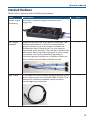
Standard Hardware
The MS-250 is delivered with the following hardware:
Part
Description
QTY
Mixed Signal
Accessory
Provides 18-channel digital acquisition and
triggering.
1
16" Digital
Leadset
Interfaces the MS-250 to the device under test. The
lead set terminates in a 25 mil pin socket. Microgripper probes of various sizes are available as
accessories from Teledyne LeCroy, and may be
connected to the lead set. The lead set is divided into
two banks. Each lead within the bank is color-coded
(to resistor color-coding standard) and has an
individual ground connection. In addition, there are
two common ground leads available for use.
1
Bus Cable
1.3m cable to connect Mixed Signal Accessory to the
main oscilloscope unit, includes USB2.0 cable. This
connection provides timebase synchronization,
cross-triggering and power.
1
5
MS-250 Mixed Signal Oscilloscope Option
Part
Description
QTY
3" Flexible
Ground Lead
Lead for grounding individual digital inputs
5
Ground
Extender
Connect to ground port of any digital input and make
a simple signal and ground connection to a 0.1”
square pin header.
20
Carrying
Case
1
Operator's
Manual
1
Quick
Reference
Guide
1
6
Operator's Manual
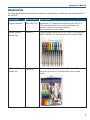
Accessories
You may purchase these optional accessories separately to enhance the performance of
an MS-250:
Accessory
Part Number
Description
Digital Leadset
MSO-DLS-18
Additional 16" leadset for inputting lines D0-D17.
This can be useful if you have more than one
device under test and don't wish to
disconnect/reconnect leads.
Large Gripper
Probe Set
PK400-1
Large gripper probe set for 0.10 inch (2.54 mm) pin
pitch. Includes 10 probes with color-coded leads.
Medium Gripper
Probe Set
PK400-2
Medium gripper probe set for 0.04 inch (1.00 mm)
pin pitch. Includes 10 probes with color-coded
leads.
7
MS-250 Mixed Signal Oscilloscope Option
Accessory
Part Number
Description
Small Gripper
Probe Set
PK400-3
Small gripper probe set for 0.008 inch (0.2 mm) pin
pitch. Includes 10 probes with color-coded leads.
Mictor Cable
MSOMICTOR
Mictor Connection cable, 16" (40.64 cm), 36
channel connector
Interconnect
Cable
MSO-3M
Interconnect cable, 16" (40.64 cm), mates with 3M
connectors 2520-6002 and 2520-5002.
8
Operator's Manual
Connecting the Mixed Signal Option
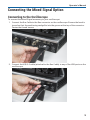
Connecting to the Oscilloscope
To connect the Mixed Signal accessory to your oscilloscope:
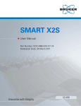
1. Connect the Bus Cable to the Bus connector on the oscilloscope. Be sure the head is
turned so that the positioning wedge fits into the groove at the top of the connector.
Fasten the thumb screws.
2. Connect the USB 2.0 cable (attached to the Bus Cable) to any of the USB ports on the
oscilloscope.
9
MS-250 Mixed Signal Oscilloscope Option
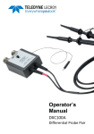
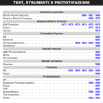
3. Connect the other end of the Bus Cable to the MS-250. Again, be sure to align the
wedge and the groove. Fasten the thumb screws.
4. Connect the other end of the USB 2.0 Cable to the MS-250.
10
Operator's Manual
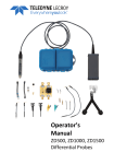
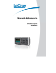
5. Connect the Digital Leadset to the Digital Inputs D0 – D17 connector on the opposite
end of the MS-250 and fasten the thumb screws.
NOTE: Each digital line has a ground connection for optimal performance. Two
additional ground leads common to the whole leadset are also available.
11
MS-250 Mixed Signal Oscilloscope Option
Digital Connections
Connect the Digital Leads to the digital lines you wish to observe (using accessory microgrippers, if desired).
Digital Banks
Each 18-channel lead set is divided into two physical banks of 9 leads, and each bank is
bundled with a plastic separator.
When connecting the leads, note that each bank (D0-D7, D8-D15, etc.) will share the same
Logic Family (or custom logic Threshold), regardless of how the individual lines are
assigned to digital bus groups.
Connector Colors
The leads in each bank use 9 repeating colors. The color sequence corresponds to the
resistor color code, making it easier to know the digital line number without having to look
at the label.
Standard Output Connection
The standard terminations on the digital leadset can be pushed directly onto 25-mil pins.
MicroGrippers or NanoGrippers may also be used to probe the test circuit’s pins. Teledyne
LeCroy provides a selection of small, medium, and large grippers for various pitch sizes. A
more complete selection of adapter probes is available for most chips from Emulation
Technology Inc., Yamaichi Inc., and other manufacturers.
12
Operator's Manual
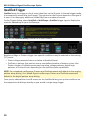
Digital Setup
Digital Logic Setup
Each lead bank requires a Logic Setup to determine the assignment of a 1 or 0, depending
on the measured voltage relative to the Threshold.
Threshold Level
The threshold level determines how the input signal is interpreted. Input voltages less than
the threshold are converted to 0, while input voltages greater than the threshold are
converted to 1.
To set Threshold:
1. Go to Vertical > Digital 1 Setup to Display the Digital Setup dialog. Open the Logic
Setup tab.
2. For each available lead bank, Touch Logic Family and either chose one of the
standard families or User Defined.
TTL circuits use a threshold voltage level of 1.58 V. ECL circuits use a threshold
voltage level of -1.39 V.
3. If you chose User Defined, enter a custom Threshold and Hysteresis.
Custom threshold levels can be set between –10.0 V and +10.0 V.
13
MS-250 Mixed Signal Oscilloscope Option
Minimum Voltage Swing (Hysteresis)
You can define the minimum high voltage and maximum low voltage levels using the
Hysteresis controls.
l
Minimum high voltage may be set up to 1.4 V above the threshold.
l
Maximum low voltage may be set up to 1.4 V below the threshold.
The minimum signal swing is 100 mV. The indeterminate range of 50 mV around the
threshold voltage level is the level below which the MS-500 will not operate. However, the
MS-250 can support a signal as low as 100 mV only if the input signal’s quality is
adequate.
14
Operator's Manual
Digital Group Setup
This procedure organizes the digital lines into groups, which correspond to buses. The
lines within a single group can be displayed individually, or collapsed into a Bus trace.
You can set up a total of two, distinct groups: Digital1 and Digital2 . Each group is
designated by its own Digital setup dialog.
Any lines from any lead bank can be combined into a single group, and individual lines
can be assigned to as many groups as you wish.
NOTE: While lines can be combined in any way, each lead bank can only have a single
logic setup, so be aware of that when choosing lines.
1. Go to Vertical > Digital 1 Setup to Display the Digital Setup dialog.
2. Open the dialog for the group you wish to configure (e.g., Digital1).
3. Check the box for each line to be added to the group. If a line is in a bank other than
the one displayed, touch the left or right arrow buttons until that bank is shown on
the dialog.
TIP: Use the All Lines Off and All Lines On buttons to quickly deselect/select lines.
NOTE: Along the bottom of the dialog is an indicator for each line in all the lead banks. As
add lines to the group, the indicator is checked, so you can always see all the lines
currently in the group. You can also use these checkboxes to select lines.
15
MS-250 Mixed Signal Oscilloscope Option
Displaying Digital Traces
The Trace On checkbox is selected by default, so if you are connected to a live input, you
should see digital traces appear as you add lines to the group.
To turn off the trace display, clear Trace On.
CAUTION. Do not use the All Lines Off or All Lines On buttons to control the display.
Doing so will erase your digital group set up. Use the Trace On checkbox to show or
hide the traces.
Position Traces
In Position, enter the number of divisions (positive or negative) relative to the zero line of
the grid where the display begins.The top of the first trace appears at this position.
In Line Height, enter the total number of grid divisions each line should occupy. The
selected traces (Line or Bus) will appear in this much space.
Individual traces are resized to fit the total number of divisions available. In the example
below, each trace takes up one division.
To move the entire group of traces to another grid, touch the Next Grid button at the bottom
right of the dialog.
NOTE: This button will only appear if your oscilloscope has this capability.
Change Trace Style
When Trace On is enabled, digital Line traces show the state of each line relative to the
threshold. You can also view a digital Bus trace that collapses all the lines in a group into
their Hex values. At the far right of the dialog, choose to either:
l
l
Expand the group into individual line traces. The size and placement of the lines
depend on the number of lines, the Vertical Position and Line Height settings.
Collapse the group into a single bus trace.
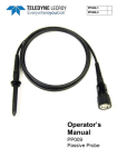
Digital line traces 1 division high starting at position 4 (top of grid).
16
Operator's Manual
Digital bus trace 1 division high starting at position 4.
Store Display
To store the entire group and display setup to an internal memory, touch the Store button
at the far right of the dialog. You can recall this setup to the grid in the future by choosing
Math > Memory Setup and selecting Trace On for the respective memory.
Renaming Digital Lines
You can give each line a user-defined name to make the interface more intuitive.
1. Touch the Dx button immediately below the Dx selection checkbox (the words
"Change Line Name" appear at the far left of the row).
2. Use the virtual keyboard that appears on the touch screen to enter a new name. When
finished, click OK.
The new line name now appears on the Dx button, instead of the original line number.
The number remains over the checkbox.
NOTE: The number of letters that appear will depend on the resolution of your oscilloscope
display. Keep names short so lines are easily identifiable.
17
MS-250 Mixed Signal Oscilloscope Option
Digital Triggering
Setting Up Digital Triggers
To access the Trigger setup dialogs, do one of the following:
l
Choose Trigger > Trigger Setup from the menu bar
l
Press the front panel Trigger Setup button
l
Touch the Trigger descriptor box
The main Trigger dialog contains the trigger type selections.
Other controls will appear depending on the trigger type selection (e.g., Slope for Edge
triggers). These are described in the set up procedures for each trigger.
The trigger condition is summarized in a preview window at the far right of the Trigger
dialog. Refer to this to confirm your selections are producing the trigger you want.
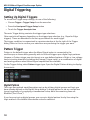
Pattern Trigger
Pattern is the default trigger when the Mixed Signal option is connected to the
oscilloscope, as these users generally wish to find and trigger upon digital logic patterns.
However, a Pattern trigger can also be set on a user-defined pattern of High or Low voltage
levels in analog channels (including the External Trigger input), or a combination of digital
and analog patterns when Mixed Signal capabilities are available.
On the Trigger dialog, select Pattern trigger type. Open the Digital Pattern dialog to display
the controls.
Digital Pattern
The Logic Bus method simplifies pattern set up by utilizing digital groups and logic you
have already defined on the Digital Setup dialogs. A digital pattern is set on a single bus
(group) manually or by applying a hexadecimal value, while the remaining lines are
disabled ("Don't Care").
If you have not set up digital groups, you can set a digital pattern line by line using the
Logic method. All available lines remain active for selection.
18
Operator's Manual
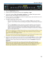
1. Open the Digital Pattern dialog.
2. At the far right of the dialog, choose either Logic Bus or Logic.
3. Optionally, deselect Filter Out Unstable Conditions. This default filter ignores short
glitches in logic state triggers that last less than 3.5 ns.
4. If using Logic Bus, touch Source and select the digital group. Any lines that are not in
this group will now be disabled.
5. To apply a digital logic pattern, either:
l
l
Enter the hexadecimal value of the pattern (in Hex or Value). Lines will take a
logical 1, 0, or X ("Don't Care") according to the pattern. Disabled lines will remain
X.
Touch the Dx button for each active line, and select whether it must be High or
Low compared to the logic threshold. Depending on your selection, a logical 1
(High) or 0 (Low) now appears on the dialog. Leave X selected for any line you
wish to exclude from the pattern. Use the Left and Right Arrow buttons to display
lines in other digital banks.
NOTE: As an alternative to a digital logic pattern, you may set edge conditions on any
line. Touch the Dx button and choose the edge. Edge conditions always assume a
logical OR in the overall trigger criteria.
TIP: As you work, the checkboxes along the bottom of the dialog will change to show
the pattern. You can also use these checkboxes to make selections.
6. If you have not already set a logic threshold, open the Levels dialog and select a Logic
Family for each digital bank from which you've selected lines. To set a custom logic
threshold, choose Logic Family User Defined, then enter the Threshold voltage and
Hysteresis.
NOTE: Digital lines inherit the Logic Setup made when defining digital groups.
However, you can change the logic threshold on the Levels dialog, as well. The two
settings are linked; they will always reflect whatever was last selected on either
dialog. Logic thresholds can only be set per lead bank, not individual line.
19
MS-250 Mixed Signal Oscilloscope Option
Analog Pattern
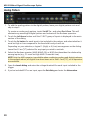
1. To add the analog pattern to the digital pattern, leave your digital pattern as is and
skip to step 2.
To create an analog-only pattern, touch Set All To... and select Don't Care. This will
eliminate any meaningful digital pattern and activate all the Boolean operators.
2. Touch the Left Arrow button until the C1-EXT group of inputs is displayed in the main
section of the dialog.
3. Touch the Cx button for each input to be included in the pattern, and select whether it
must be High or Low compared to the threshold Level you will set.
Depending on your selection, a logical 1 (High) or 0 (Low) now appears on the dialog.
Leave Don't Care ("X") selected for any input you wish to exclude.
4. Select the Boolean operator (AND, NAND, OR, or NOR) that describes the relationship
among inputs (e.g., C1 must be High AND C2 must be Low).
NOTE:Only the AND operator is available when combining analog and digital patterns.
In the example above, all digital lines have been set to Don't Care ("X"), so all operators
are available.
5. Open the Levels dialog and enter the voltage threshold for each input included in the
trigger.
6. If you've included EXT as an input, open the Ext dialog and enter the Attenuation.
20
Operator's Manual
Edge Trigger
Edge triggers upon a achieving a certain voltage level in the positive or negative slope of
the waveform. It is the default trigger selection on standard oscilloscopes.
On the Trigger dialog, select Edge trigger type to display the controls.
1. Choose the Source digital line.
2. Choose the Slope (edge) upon which to trigger.
3. Choose the Logic Family that marks the High-Low logic threshold. To enter a custom
threshold, choose Logic Family User Defined and enter the voltage Level .
NOTE: The Logic Family will default to any Logic Setup associated with that line in a
previous digital group setup.
21
MS-250 Mixed Signal Oscilloscope Option
Width Trigger
Width triggers upon finding a positive- or negative-going pulse width when measured at the
specified voltage level.
On the Trigger dialog, select Width trigger type to display the controls.
1. Choose the Source input line.
2. Choose the line Polarity on which to trigger.
3. Choose the Logic Family that marks the High-Low logic threshold. To enter a custom
threshold, choose Logic Family User Defined and enter the voltage Level .
NOTE: The Logic Family will default to any Logic Setup associated with that line in a
previous digital group setup.
4. Use Width Condition is settings to create an expression describing the triggering pulse
width. This may be:
l
Any width Less Than an Upper Value.
l
Any width Greater Than a Lower Value.
l
22
Any width In Range or Out Range of values. You may describe the range using
either:
l
Limits, an absolute Upper Value and Lower Value.
l
Delta, any Nominal width plus or minus a Delta width.
Operator's Manual
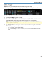
Glitch Trigger
Glitch triggers upon finding a fixed pulse-width time or time range.
On the Trigger dialog, select Smart trigger type, then Glitch to display the controls.
1. Choose the Source input line.
2. Choose the Polarity on which to trigger.
3. Choose the Logic Family that marks the High-Low logic threshold. To enter a custom
threshold, choose Logic Family User Defined and enter the voltage Level .
NOTE: The Logic Family will default to any Logic Setup associated with that line in a
previous digital group setup.
4. Use Glitch Condition is settings to create an expression describing the glitch width.
This may be:
l
l
Any width Less Than an Upper Value.
Any width In Range of values marked by the specified Upper Value and Lower
Value.
23
MS-250 Mixed Signal Oscilloscope Option
Interval Trigger
Interval triggers upon finding a specific interval, the time (period) between two
consecutive edges of the same polarity: positive to positive or negative to negative. Use the
interval trigger to capture intervals that fall short of, or exceed, a specified range.
On the Trigger dialog, select Smart trigger type, then Interval to display the controls.
1. Choose the Source input line.
2. Choose the Slope (edge) from which to measure.
3. Choose the Logic Family that marks the High-Low logic threshold. To enter a custom
threshold, choose Logic Family User Defined and enter the voltage Level .
NOTE: The Logic Family will default to any Logic Setup associated with that line in a
previous digital group setup.
4. Use Interval Condition is settings to create an expression describing the triggering
interval. This may be:
l
Any width Less Than an Upper Value.
l
Any width Greater Than a Lower Value.
l
24
Any width In Range or Out Range of values. You may describe the range using
either:
l
Limits, an absolute Upper Value and Lower Value.
l
Delta, any Nominal width plus or minus a Delta width.
Operator's Manual
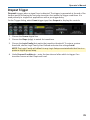
Dropout Trigger
Dropout triggers when a signal loss is detected. The trigger is generated at the end of the
timeout period following the last edge transition that meets the trigger conditions. It is
used primarily in single-shot applications with a pre-trigger delay.
On the Trigger dialog, select Smart trigger type, then Dropout to display the controls.
1. Choose the Source digital line.
2. Choose the Slope (edge) to watch for transitions.
3. Choose the Logic Family that marks the transition threshold. To enter a custom
threshold, choose Logic Family User Defined and enter the voltage Level .
NOTE: The Logic Family will default to any Logic Setup associated with that line in a
previous digital group setup.
4. Under Dropout Condition is..., enter the time interval after which to trigger if no
transition occurs at that Slope and Level.
25
MS-250 Mixed Signal Oscilloscope Option
Qualified Trigger
Qualified arms the trigger on the A event, then fires on the B event. In Normal trigger mode,
it automatically resets after the B event. The options for the B event depend on the type of
A event. You may apply additional Holdoff by time or number of events.
On the Trigger dialog, select Qualified or MultiStage > Qualified trigger type to display the
controls, depending on your oscilloscope.
Then, on the Qualified dialog choose the A and B events.
Besides an Edge or Pattern trigger, two special conditions may be selected as the arming
("A") event:
l
l
State, voltage measured above or below a threshold Level.
PatState, a pattern that persists over a user-defined number of events or time. Like
Pattern triggers, PatState events may be analog voltage patterns, digital logic
patterns, or a mix of both, depending on the oscilloscope's capabilities.
NOTE: On a standard oscilloscope, Pattern and PatState events will default to the analog
pattern setup dialog. On a Mixed-Signal oscilloscope, Pattern and PatState events will
default to the digital pattern setup dialog.
Once you've selected the A and B events on the Qualified dialog, set up the conditions on
the respective sub-dialogs exactly as you would a single-stage trigger.
26
Operator's Manual
Maintenance
Cleaning
Clean only the exterior of the product using a soft cloth moistened with water or an
alcohol solution. Do not use harsh chemicals or abrasive elements. Under no
circumstances submerge the device or allow moisture to penetrate it.
CAUTION. Do not attempt to clean internal parts. Refer to qualified service
personnel.
Calibration
Your MS-250 hardware does not need periodic calibration.
However, we do recommend that the oscilloscope used with the MS-250 be returned for
annual factory calibration. See Returning a Product for Service.
Firmware Updates
Teledyne LeCroy offers state-of-the-art performance by continually improving our
oscilloscope capabilities. We release frequent oscilloscope firmware updates that include
accessory support.
Download free firmware updates for your oscilloscope platform from:
teledynelecroy.com/support/softwaredownload
Because our software is continually changing, and accessories often may be used with
several different oscilloscopes, the dialogs you see in this manual may not exactly match
what is seen on your oscilloscope. Rest assured, however, that the functionality is the
same. Where relevant, we will note platform-specific information in the instructions.
Technical Support
Phone
Registered users can contact their local Teledyne LeCroy service center at the number
listed in this manual to make Technical Support requests by phone or email.
Web
You can also submit Technical Support requests via the website at:
teledynelecroy.com/support/techhelp.
Teledyne LeCroy publishes a free Technical Library on its website. Manuals, tutorials,
application notes, white papers, and videos are available to help you get the most out of
your Teledyne LeCroy products.
27
MS-250 Mixed Signal Oscilloscope Option
The Datasheet published on the product page contains the detailed product specifications.
You can also download Oscilloscope System Recovery Tools and Procedures, which
contains instructions for using Acronis® True Image® Home included with the
oscilloscope.
Returning a Product for Service
Contact your local Teledyne LeCroy service center for calibration or other service. If the
product cannot be serviced on location, the service center will give you a Return Material
Authorization (RMA) code and instruct you where to ship the product. All products returned
to the factory must have an RMA.
Return shipments must be prepaid. Teledyne LeCroy cannot accept COD or Collect
shipments. We recommend air-freighting. Insure the item you’re returning for at least the
replacement cost.
1. Remove all accessories from the device. Do not include the manual.
2. Pack the product in its case, surrounded by the original packing material (or
equivalent).
3. Label the case with a tag containing:
l
The RMA
l
Name and address of the owner
l
Product model and serial number
l
Description of failure or requisite service
4. Pack the product case in a cardboard shipping box with adequate padding to avoid
damage in transit.
5. Mark the outside of the box with the shipping address given to you by Teledyne
LeCroy; be sure to add the following:
l
ATTN: <RMA code assigned by Teledyne LeCroy>
l
FRAGILE
6. If returning a product to a different country:
l
l
l
Mark the shipment as a "Return of US manufactured goods for warranty
repair/recalibration."
If there is a cost for the service, list the cost in the Value column and the original
purchase price "For insurance purposes only."
Be very specific about the reason for shipment. Duties may have to be paid on the
value of the service.
Extended warranty, calibration, and upgrade plans are available for purchase. Contact your
Teledyne LeCroy sales representative to purchase a service plan.
28
Operator's Manual
Reference
Certifications
EMC Compliance
EC DECLARATION OF CONFORMITY - EMC
The product meets the intent of EC Directive 2004/108/EC for Electromagnetic
Compatibility. Compliance was demonstrated to the following specifications as listed in
the Official Journal of the European Communities:
EN 61326-1:2:2013, EN 61326-2-1:2013 EMC requirements for electrical equipment for
measurement, control, and laboratory use.
Electromagnetic Emissions:
EN 55011/A1:2010, Radiated and Conducted Emissions Group 1, Class A 1, 2
Electromagnetic Immunity:
EN 61000-4-2:2009 Electrostatic Discharge, 4 kV contact, 8 kV air, 4 kV vertical/horizontal
coupling planes
EN 61000-4-3/A2:2010 RF Radiated Electromagnetic Field, 3 V/m, 80-1000 MHz; 3 V/m,
1400 MHz - 2 GHz; 1 V/m, 2 GHz - 2.7 GHz
1 Emissions which exceed the levels required by this standard may occur when the
product is connected to a test object.
2 This product is intended for use in nonresidential areas only. Use in residential areas
may cause electromagnetic interference.
European Contact:
Teledyne LeCroy Europe GmbH
Waldhofer Str 104
D-69123 Heidelberg
Germany
Tel: (49) 6221 82700
AUSTRALIA & NEW ZEALAND DECLARATION OF CONFORMITY—EMC
The product complies with the EMC provision of the Radio Communications Act per the
following standards, in accordance with requirements imposed by Australian
Communication and Media Authority (ACMA):
E55011/A1:2010 Radiated and Conducted Emissions, Group 1, Class A, in accordance
with EN61326-1:2013 and EN61326-2-1:2013.
Australia / New Zealand Contacts:
Vicom Australia Ltd.
1064 Centre Road
Oakleigh, South Victoria 3167
Australia
Vicom New Zealand Ltd.
60 Grafton Road
Auckland
New Zealand
29
MS-250 Mixed Signal Oscilloscope Option
Safety Compliance
EC DECLARATION OF CONFORMITY - LOW-VOLTAGE
The product meets the intent of EC Directive 2006/95/EC for Product Safety. Compliance
was demonstrated to the following specifications as listed in the Official Journal of the
European Communities:
EN 61010-031:2002/A1:2008 Safety requirements for electrical equipment for
measurement, control, and laboratory use – Part 031: Safety requirements for hand-held
probe assemblies for electrical measurement and test.
Environmental Compliance
END-OF-LIFE HANDLING
The product is marked with this symbol to indicate that it complies with the
applicable European Union requirements to Directives 2002/96/EC and
2006/66/EC on Waste Electrical and Electronic Equipment (WEEE) and
Batteries.
The product is subject to disposal and recycling regulations that vary by
country and region. Many countries prohibit the disposal of waste electronic
equipment in standard waste receptacles. For more information about proper
disposal and recycling of your Teledyne LeCroy product, please visit
teledynelecroy.com/recycle.
RESTRICTION OF HAZARDOUS SUBSTANCES (ROHS)
The product and its accessories conform to the 2011/65/EU RoHS2 Directive, as they have
been classified as Industrial Monitoring and Control Equipment (per Article 3, Paragraph
24) and are exempt from RoHS compliance until 22 July 2017 (per Article 4, Paragraph 3).
30
Operator's Manual
Warranty
THE WARRANTY BELOW REPLACES ALL OTHER WARRANTIES, EXPRESSED OR IMPLIED,
INCLUDING BUT NOT LIMITED TO ANY IMPLIED WARRANTY OF MERCHANTABILITY,
FITNESS, OR ADEQUACY FOR ANY PARTICULAR PURPOSE OR USE. TELEDYNE LECROY
SHALL NOT BE LIABLE FOR ANY SPECIAL, INCIDENTAL, OR CONSEQUENTIAL DAMAGES,
WHETHER IN CONTRACT OR OTHERWISE. THE CUSTOMER IS RESPONSIBLE FOR THE
TRANSPORTATION AND INSURANCE CHARGES FOR THE RETURN OF PRODUCTS TO
THE SERVICE FACILITY. TELEDYNE LECROY WILL RETURN ALL PRODUCTS UNDER
WARRANTY WITH TRANSPORT PREPAID.
The product is warranted for normal use and operation, within specifications, for a period
of three years from shipment. Teledyne LeCroy will either repair or, at our option, replace
any product returned to one of our authorized service centers within this period. However,
in order to do this we must first examine the product and find that it is defective due to
workmanship or materials and not due to misuse, neglect, accident, or abnormal
conditions or operation.
Teledyne LeCroy shall not be responsible for any defect, damage, or failure caused by any
of the following: a) attempted repairs or installations by personnel other than Teledyne
LeCroy representatives or b) improper connection to incompatible equipment, or c) for any
damage or malfunction caused by the use of non-Teledyne LeCroy supplies. Furthermore,
Teledyne LeCroy shall not be obligated to service a product that has been modified or
integrated where the modification or integration increases the task duration or difficulty of
servicing the oscilloscope. Spare and replacement parts, and repairs, all have a 90-day
warranty.
Products not made by Teledyne LeCroy are covered solely by the warranty of the original
equipment manufacturer.
31
MS-250 Mixed Signal Oscilloscope Option
Contact Us
United States and Canada World Wide Corporate Office
Teledyne LeCroy Corporation
700 Chestnut Ridge Road
Chestnut Ridge, NY, 10977-6499, USA
Ph: 800-553-2769 / 845-425-2000
FAX: 845-578-5985
teledynelecroy.com
[email protected]
[email protected]
United States - Protocol Solutions Group
Teledyne LeCroy Corporation
3385 Scott Boulevard
Santa Clara, CA, 95054, USA
FAX: 408-727-0800
teledynelecroy.com
Sales and Service:
Ph: 800-909-7211 / 408-727-6600
[email protected]
Support: 800-909-7112 / 408-653-1260
[email protected]
European Headquarters
Teledyne LeCroy SA
4, Rue Moïse Marcinhes
Case postale 341
1217 Meyrin 1
Geneva, Switzerland
Ph: + 41 22 719 2228 / 2323 / 2277
FAX: +41 22 719 2233
[email protected]
[email protected]
teledynelecroy.com/europe
Protocol Analyzers:
Ph: +44 12 765 03971
Singapore, Oscilloscopes
Teledyne LeCroy Singapore Pte Ltd.
Blk 750C Chai Chee Road #02-08
Technopark @ Chai Chee
Singapore 469003
Ph: ++ 65 64424880
FAX: ++ 65 64427811
32
Singapore, Protocol Analyzers
Genetron Singapore Pte Ltd.
37 Kallang Pudding Road, #08-08
Tong Lee Building Block B
Singapore 349315
Ph: ++ 65 9760-4682
China
Teledyne LeCroy Corporation Beijing
Rm. 2001
Unit A, Horizon Plaza
No. 6, Zhichun Road, Haidian District
Beijing 100088, China
Ph: ++86 10 8280 0318 / 0319 / 0320
FAX:++86 10 8280 0316
Service: Rm. 2002
Ph: ++86 10 8280 0245
Taiwan
LeColn Technology Co Ltd.
Far East Century Park, C3, 9F
No. 2, Chien-8th Road,
Chung-Ho Dist., New Taipei City, Taiwan
Ph: ++ 886 2 8226 1366
FAX: ++ 886 2 8226 1368
Korea
Teledyne LeCroy Korea
10th fl.Ildong Bldg.
968-5 Daechi-dong, Gangnam-gu
Seoul 135-280, Korea
Ph: ++ 82 2 3452 0400
FAX: ++ 82 2 3452 0490
Japan
Teledyne LeCroy Japan
Hobunsya Funchu Bldg, 3F
3-11-5, Midori-cho, Fuchu-Shi
Tokyo 183-0006, Japan
Ph: ++ 81 4 2402 9400
FAX: ++ 81 4 2402 9586
teledynelecroy.com/japan
924976-00
924976-00
November, 2014