1
MLDV
Direct Vent Gas Fireplace
Model: MLDV500
Installation & Operating
Instructions
WARNING
If the information in these instructions is not
followed exactly, a fire or explosion may
result causing property damage, personal
injury or loss of life.
– Do not store or use gasoline or other flammable
vapors and liquids in the vicinity of this or any other
appliance.
– WHAT TO DO IF YOU SMELL GAS
• Do not try to light any appliance.
• Do not touch any electrical switch; do not use any
phone in your building.
• Immediately call your gas supplier from a neighbor's
phone. Follow the gas supplier's instructions.
• If you cannot reach your gas supplier, call the fire
department.
– Installation and service must be performed
by a qualified installer, service agency or the
gas supplier.
WARNING: Improper installation, adjustment, alteration,
services or maintenance can cause injury or property
damage. Refer to this manual. For assistance or additional
information consult a qualified installer, service agency
or the gas supplier.
This appliance may be installed in an aftermarket*,
permanently located, manufactured home (USA only) or
mobile home, where not prohibited by local codes.
This appliance is only for use with the type of gas
indicated on the rating plate. This appliance is not
convertible for use with other gases, unless a certified
kit is used.
* Aftermarket: Completion of sale, not for purpose of resale, from the
manufacturer.
75d0004
MLDV cover
DUE TO HIGH TEMPERATURES, THE APPLIANCE
SHOULD BE LOCATED OUT OF TRAFFIC AND
AWAY FROM FURNITURE AND DRAPERIES.
CHILDREN AND ADULTS SHOULD BE ALERTED
TO THE HAZARDS OF HIGH SURFACE
TEMPERATURE AND SHOULD STAY AWAY TO
AVOID BURNS OR CLOTHING IGNITION.
YOUNG CHILDREN SHOULD BE SUPERVISED
WHEN THEY ARE IN THE SAME ROOM AS THE
APPLIANCE.
CLOTHING OR OTHER FLAMMABLE MATERIAL
SHOULD NOT BE PLACED ON OR NEAR THE
APPLIANCE.
Keep the room area clear and free
from combustible materials, gasoline,
and other flammable vapors and
liquids.
INSTALLER: Leave this manual with the appliance.
CONSUMER: Retain this manual for future reference.
75D0004 3/13 Rev. 15
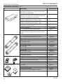
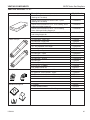
CONTENTS
MLDV Series Gas Fireplace
Thank you and congratulations on your purchase of a
Vermont Castings Group Fireplace.
PLEASE READ THE INSTALLATION AND OPERATION INSTRUCTIONS BEFORE USING THE APPLIANCE!
IMPORTANT: Read all instructions and warnings carefully before starting installation.
Failure to follow these instructions may result in a possible fire hazard and will void the warranty.
Important Safety Information...................................... 3
Checking Gas Pressure - SCS ................................. 36
Code Approval.............................................................. 4
Electrical Wiring - SCS . ............................................ 36
Junction Box Wiring............................................... 37
Command Center Wall Installation......................... 37
Wall Switch Installation.......................................... 37
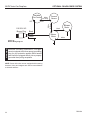
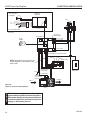
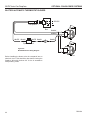
Signature Command Wiring Diagram.................... 38
Product Specifications................................................ 5
High Elevations........................................................ 5
Gas Pressures......................................................... 5
Gas Specifications & Orifice Size............................ 5
Fireplace & Framing Dimensions .............................. 6
Pre-Installation Information......................................... 7
Before You Start....................................................... 7
Items Required for Installation................................. 7
Firebox Framing....................................................... 7
Fireplace Location.................................................... 7
Clearances.................................................................... 8
Secure Fireplace to Floor or Framing........................ 9
Finishing Material..................................................... 9
Venting Installation..................................................... 10
Installation Precautions.......................................... 10
Optional Top Vent Application................................ 11
Vent Pipe Clearances............................................ 12
Installation Planning............................................... 13
Horizontal & Vertical Terminations......................... 13
Termination Location.............................................. 14
Termination Clearances......................................... 15
How to Use the Vent Graph................................... 15
Rear Wall Vent Installation..................................... 16
Horizontal w/Vertical Rise Termination Config....... 17
Below Grade Installations...................................... 20
Vertical Through-the-Roof Applications.................. 21
Installation for Vertical Termination........................ 22
Flat Ceiling Installation........................................... 22
Flex Vent Installation.............................................. 24
Fireplace Installation.................................................. 27
Check Gas Type.................................................... 27
Gas Line Installation.............................................. 27
Check Gas Pressure - Millivolt ................................. 29
Electrical Installation - Millivolt................................. 29
Remote Wall Mounted Switch................................ 30
Optional Fan/Blower - BLOTBLDV)....................... 30
Operating Instructions - Millivolt.............................. 33
For Your Safety...................................................... 33
Lighting Pilot for the First Time.............................. 33
Lighting Pilot.......................................................... 34
Lighting Burner....................................................... 35
Optional Fan/Blower System - SCS.......................... 39
BLOTSDVSC......................................................... 39
BLOTSDV.............................................................. 40
Operating Instructions - SCS.................................... 41
For Your Safety...................................................... 41
Operating Instructions............................................ 42
To Turn Off Gas To Appliance................................ 42
Signature Command System Operation.................. 43
Final Installation......................................................... 46
Glass Frame Removal........................................... 46
Brick Installation..................................................... 46
Optional Eyebrow/Canopy Installation................... 46
Rockwool Placement............................................. 47
Log Placement....................................................... 47
Cleaning and Maintenance........................................ 50
Burner, Pilot and Control Compartment................. 50
Pilot Flame............................................................. 50
Burner Flame......................................................... 50
Vent System........................................................... 51
Glass Door............................................................. 51
Logs....................................................................... 51
Rock Wool . ........................................................... 51
Troubleshooting......................................................... 52
Standing Pilot Ignition............................................ 52
Signature Command System................................. 54
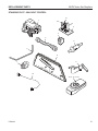
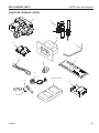
Replacement Parts..................................................... 55
Firebox Components.............................................. 55
Logs....................................................................... 56
Standing Pilot Millivolt Control .............................. 57
Signature Command System................................. 59
Venting Components.............................................. 61
Massachusetts Residents Only................................ 66
Warranty...................................................................... 67
Efficiencies................................................................. 68
75D0004
IMPORTANT SAFETY INFORMATION
MLDV Series Gas Fireplace
OWNER
Please leave these instructions with the appliance.
Please retain these instructions for future reference.
WARNING
INSTALLER
• Read this owner’s manual carefully and completely before trying to assemble,
operate, or service this fireplace.
• Any change to this fireplace or its controls can be dangerous.
• Improper installation or use of this fireplace can cause serious injury or
death from fire, burns, explosions, electrical shock and carbon monoxide
poisoning.
This fireplace is a vented product. This fireplace must be
properly installed by a qualified service person. The glass
door must be properly seated and sealed. If this unit is not
properly installed by a qualified service person with glass
door properly seated and sealed, combustion leakage
can occur.
CARBON MONOXIDE POISONING: Early signs of carbon
monoxide poisoning are similar to the flu with headaches,
dizziness and/or nausea. If you have these signs, the fireplace may not have been installed properly. Get fresh air
at once! Have the fireplace inspected and serviced by a
qualified service person. Some people are more affected
by carbon monoxide than others. These include pregnant
women, people with heart or lung disease or anemia,
those under the influence of alcohol, and those at high
altitudes.
Propane/LP gas and natural gas are both odorless. An
odor-making agent is added to each of these gases. The
odor helps you detect a gas leak. However, the odor added
to these gases can fade. Gas may be present even though
no odor exists.
Make certain you read and understand all warnings. Keep
this manual for reference. It is your guide to safe and proper
operation of this fireplace.
1. This appliance is only for use with the type of gas
indicated on the rating plate. This appliance is not
convertible for use with other gases unless a certified
kit is used.
2. For propane/LP fireplace, do not place propane/LP
supply tank(s) inside any structure. Locate propane/
LP supply tank(s) outdoors. To prevent performance
problems, do not use propane/LP fuel tank of less than
100 lbs. capacity.
3. If you smell gas
• shut off gas supply.
• do not try to light any appliance.
• do not touch any electrical switch; do not use any
phone in your building .
• immediately call your gas supplier from a neighbor’s
phone. Follow the gas supplier’s instructions.
75D0004
4.
Never install the fireplace
• in a recreational vehicle
• where curtains, furniture, clothing, or other flam-
mable objects are less than 42" from the front, top,
or sides of the fireplace
• in high traffic areas
• in windy or drafty areas
5. This fireplace reaches high temperatures. Keep children and adults away from hot surfaces to avoid burns
or clothing ignition. Fireplace will remain hot for a time
after shutdown. Allow surfaces to cool before touching.
6. Young children should be carefully supervised when
they are in the same room as the appliance. Toddlers,
young children and others may be susceptible to
accidental contact burns. A physical barrier is recommended if there are at risk individuals in the house. To
restrict access to a fireplace or stove, install an adjustable safety gate to keep toddlers, young children and
other at risk individuals out of the room and away from
hot surfaces.
7. Do not modify fireplace under any circumstances. Any
parts removed for servicing must be replaced prior to
operating fireplace.
8. Turn fireplace off and let cool before servicing, installing, or repairing. Only a qualified service person should
install, service, or repair the fireplace. Have burner
system inspected annually by a qualified service
person.
9. You must keep control compartments, burners, and
circulating air passages clean. More frequent cleaning may be needed due to excessive lint and dust.
Turn off the gas valve and pilot light before cleaning
fireplace.
10. Have venting system inspected annually by a qualified service person. If needed, have venting system
cleaned or repaired. See Cleaning and Maintenance,
Page 50.
11. Keep the area around your fireplace clear of combustible materials, gasoline, and other flammable vapor
and liquids. Do not run fireplace where these are used
or stored. Do not place items such as clothing or decorations on or around fireplace.
IMPORTANT SAFETY INFORMATION
MLDV Series Gas Fireplace
IMPORTANT:
PLEASE READ THE FOLLOWING
CAREFULLY
It is normal for fireplaces fabricated of steel to give off
some expansion and/or contraction noises during the
start up or cool down cycle. Similar noises are found with
your furnace heat exchanger or car engine.
IMPORTANT:
PLEASE READ THE FOLLOWING
CAREFULLY
It is not unusual for gas fireplaces to give off some odor
the first time it is burned. This is due to the manufacturing
process.
Please ensure that your room is well ventilated
during burn off — open all windows.
It is recommended that you burn your fireplace for at
least ten (10) hours the first time you use it. Place the
fan switch in the “OFF” position during this time.
WARNING
12. Do not use this fireplace to cook food or burn paper or
other objects.
13. Never place anything on top of fireplace.
14. Do not use any solid fuels (wood, coal, paper, cardboard, etc.) in this fireplace. Use only the gas type
indicated on rating plate.
15. This appliance, when installed, must be electrically
grounded in accordance with local codes or in the
absence of local codes, with the National Electrical
Code, ANSI/NFPA 70, or the Canadian Electrical Code,
CSA C22.1.
16. Do not obstruct the flow of combustion and ventilation
air in any way. Provide adequate clearances around
air openings into the combustion chamber along with
adequate accessibility clearance for servicing and
proper operation.
17. When the appliance is installed directly on carpeting,
tile or other combustible material other than wood
flooring, you must set appliance on a metal or wood
panel or hearth pad extending the full width and depth
of the appliance.
18. Do not use fireplace if any part has been exposed to
or has been under water. Immediately call a qualified
service technician to inspect the appliance and replace
any part of the control system and any gas control
which as been submerged in water.
19. Do not operate fireplace if any log is broken.
20. Do not use a blower insert, heat exchanger insert, or
any other accessory not approved for use with this
fireplace.
21. Do not operate the fireplace with glass door removed,
cracked, or broken.
Never connect unit to private (nonutility) gas wells. This gas is commonly
known as wellhead gas.
Code Approval
Direct Vent type appliances draw all combustion air from
outside of the dwelling through the vent pipe.
These appliances have been tested by CSA and found to
comply with the established standards for DIRECT VENT
GAS FIREPLACE HEATERS in the USA and Canada as
follows:
LISTED VENTED GAS FIREPLACE HEATER
TESTED TO:
ANSI Z21.88-2009 / CSA 2.33-2009 STANDARDS
A manufactured home (USA only) or mobile home OEM
installation must conform with the Manufactured Home
Construction and Safety Standard, Title 24 CFR, Part
3280, or when such a standard is not applicable, the
Standard for Manufactured Home Installations, ANSI/
NCSBCS A225.1, or Standard for Gas Equipped Recreational Vehicles and Mobile Housing, CSA Z240.4.
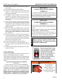
!
WARNING
HOT GLASS WILL
Nous recommandons
que nos
CAUSE BURNS.
appareils de chauffage au gaz
DO NOT TOUCH GLASS
soient installés et entretenus par
UNTIL COOLED.
des professionnels qui ont été
NEVER ALLOW CHILDREN
accrédités
aux È.U. par le National
TO TOUCH GLASS.
Fireplace Institute
® (NFI) comme
étant des spécialistes du NFI en
matièred’appareils de chauffage
au gaz.
75D0004
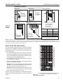
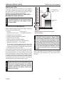
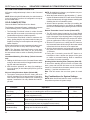
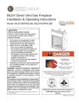
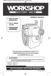
product features
MLDV Series Gas Fireplace
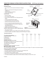
product SPECIFICATIONS
• This appliance has been certified for use with
•
•
•
•
•
•
Insulation Board
either natural or propane gas. See appropriate
data plates.
This appliance is not for use with solid fuels.
The appliance is approved for bedroom or bedsitting room installations.
The appliance must be installed in accordance
with local codes if any. If none exist use the current installation code. ANSI Z223.1/NFPA 54 in
the USA, CSA B149 in Canada.
This appliance is mobile home appr-oved.
The appliance must be properly connected to a
venting system.
The appliance is not approved for closet or
recessed installations.
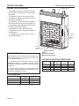
5/8" Nailing
Flange
1/2" Nailing
Flange
Ignitor
On/Off/RS
Switch
HIGH ELEVATIONS
Input ratings are shown in BTU per hour and are certified without deration for elevations up to 4,500 feet
(1,370 m) above sea level.
For elevations above 4,500 feet (1,370 m) in USA,
installation must be in accordance with the current
ANSI Z223.1/NFPA 54 and/or local codes having
jurisdiction.
In Canada, please consult provincial and/or local
authorities having jurisdiction for installation at elevations above 4,500 feet (1,370 m).
Hi/Lo Knob
FP1984
Off/Pilot/On Knob
Figure 1 MLDV Series Fireplace
(Millivolt Control shown)
FP1984
MLDV components
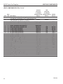
Gas Specifications & ORIFICE SIZE
Model
Fuel
MLDV500NV Nat.
MLDV500PV
LP
MLDV500NSC Nat.
MLDV500PSC LP
Max.Input Min. Input
BTU/h
BTU/h
34,00022,000
34,00027,000
34,00022,000
34,00027,000
Orifice
Size
#33
1.8 mm
#33
1.8 mm
GAS pressures
Inlet Minimum
Inlet Maximum
Manifold Pressure
75D0004
Natural Propane (LP)
4.5” w.c.
11.0” w.c.
10.5” w.c.
13.0” w.c.
3.5” w.c.
10.0” w.c.
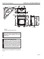
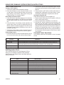
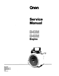
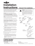
FIREPLACE and FRAMING DIMENSIONS
MLDV Series Gas Fireplace
2256M”
(565 mm)
2256M”
(565 mm)
(9 36
21 56M
m ”
m
)
m
m
)
1/2” or 5/8”
91
Min. Rough Opening Width
(4256O” 91080 mm)
17
56O
” (
72
5256M” (1327 mm)
5256M” (1327 mm)
30(6” (784 mm)
206”
(524 mm)
Min. Rough
Opening Depth
Min. Rough
Opening
Height
6”
(152 mm)
9556QE”
(246 mm)
50(6”
(1292 mm)
506M”
(1289 mm)
33” (838 mm)
276QE”
(694 mm)
34”
(864 mm)
356”
(79 mm)
256O"
(64 mm)
36” (914 mm)
41” (1041 mm)
76”
(187 mm)
1”
(25 mm)
156O”
(38 mm)
386M”
(984 mm)
446”
(1133 mm)
466”
(1184 mm)
1456O”
(368 mm)
2”
(51 mm)
WARNING
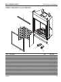
Figure 2 Fireplace and Framing Dimensions
750005
Do not fill spaces around firebox
with
DVML MLDV dims
insulation or other materials. This could
cause a fire.
NOTE
COLD CLIMATE INSULATION
If you live in a cold climate, seal all cracks
around your appliance, and wherever cold air
could enter the room, with noncombustible
material. It is especially important to insulate
the outside chase cavity between the studs
and under the floor on which the appliance
rests, if the floor is above ground level.
NOTE: Refer to cold climate pilot information on Page 44
for more information on standing pilot vs. intermittent pilot
options.
75D0004
installation information
MLDV Series Gas Fireplace
Before You Start
Fireplace Location
Read this homeowner manual thoroughly and follow all
instructions carefully. Inspect all contents for shipping
damage and immediately inform your dealer if any damage
is found. Do not install any unit with damaged, incomplete,
or substitute parts. Check your packing list to verify that
all listed parts have been received. You should have the
following:
• Fireplace (Firebox and Burner System)
• Log Set
• Rock Wool
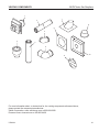
ITEMS REQUIRED FOR INSTALLATION
Tools and Building Materials
• Phillips Screwdriver • Framing Materials
• Hammer
• Wall Finishing Materials
• Saw and/or saber saw • Level
• Measuring Tape
• Pliers
• Electric Drill and Bits • Square
• Pipe Wrench
• Tee Joint
• Caulking Material (noncombustible)
• Fireplace Surround Material (noncombustible)
• Piping Complying with Local Codes
• Pipe Sealant Approved for use with Propane/LPG
Plan for the installation of your appliance. This includes
determining where the unit is to be installed, the vent configuration to be used, framing and finishing details, and
whether any optional accessories (i.e. blower, wall switch,
or remote control) are desired. Consult your local building
code agency to ensure compliance with local codes, including permits and inspections.
The following factors should be taken into consideration:
• Clearance to side-wall, ceiling, woodwork, and windows.
•
•
•
•
•
•
(Resistant to sulfur compounds)
firebox framing
Firebox framing can be built before or after the appliance
is set in place. Construct firebox framing following Figure 2
for firebox and framing dimensions. The framing headers
may rest on the top of the firebox standoffs. Do not bring
headers below top of standoffs. NOTE: When planning your
framing and installation, keep in mind that your gas line will
come in on the right side of the box (as you are facing it)
and your electricity will come in on the left side.
The firebox may be installed directly on a combustible floor
or raised on a platform of an appropriate height. When
the firebox is installed directly on carpeting, tile, or other
combustible material, other than wood flooring, the firebox
shall be installed on a metal or wood panel extending the
full width and depth of the enclosure.
•
Minimum clearances to combustibles must be maintained.
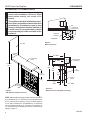
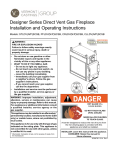
This fireplace may be installed along a wall, across a
corner, or use an exterior chase. Refer to Figure 3 for
suggested locations.
Location should be out of high traffic areas and away
from furniture and draperies due to heat from appliance.
Never obstruct the front opening of the fireplace.
Do not install in the vicinity where gasoline or other
flammable liquids may be stored.
Vent pipe routing. See Venting section found in this
manual for allowable venting configurations.
These units can be installed in a bedroom. See National
Fuel Gas Code ANSI Z233.1/NFPA 54 — (current
edition), the Uniform Mechanical Code — (current edition), and Local Building Codes for specific installation
requirements.
These units can be installed in a bathroom.
Y
E
A
X
C
Y
D
F
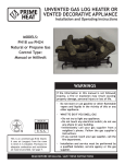
Figure 3 Locate Gas Fireplace
75D0004
B
A
B
C
D
E
F
Y
Flat on Wall
Cross Corner
Island**
Room Divider*
Flat on Wall Corner*
Chase Installation
6" Minimum
** Island (C) and room divider (D) installation is possible as long as the
horizontal portion of vent system (X) does not exceed 20'. See Install
Horizontal Termination Configuration on Pages 18 and 19.
* When you install your fireplace in (D) room divider or (E) flat on wall
corner positions (Y), a minimum of 6" clearance must be maintained
from perpendicular wall and front of fireplace.
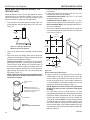
clearances
MLDV Series Gas Fireplace
WARNING
Clearances to combustibles
Follow these instructions carefully to
ensure safe installation. Failure to follow
instructions exactly can create a fire
hazard.
The appliance cannot be installed on a carpet,
tile or other combustible material other than
wood flooring. If installed on carpet or vinyl
flooring, the appliance shall be installed on
a metal, wood or noncombustible material
panel extending full width and depth of the
appliance.
Wall
Combustible
Material Area
1"
Fireplace
Opening
156O"
256O"
356O"
456O"
45°
3"
5"
6"
Top View
Figure 5 Mantel clearances.
Side Wall
FP1949
mantel clearances
12” Max.
Depth
12” Max.
Combustible
Mantel
Combustible
Breastplate
8” Max.
71” Minimum
Ceiling
14”
Min.
10”
Min.
3/4"
Marble
756O”
Min.
14” Min.
From Opening
Eyebrow
Canopy
6” Min.
to Opening
Figure 4 Side Wall and Ceiling Clearances
156O”
Max.
256M” Max.
Figure 5a Mantel Clearance with Eyebrow Canopy
FP2916
Mantel Clearance
NOTE: When eyebrow canopy is used, minimum clearance
to combustibles is 2Z\v" maximum out from fireplace front
at 7Z\x" minimum from opening. Figure 5a. When eyebrow
is not used, clearances
to combustibles is 8" maximum
FP1987
out from fireplaceclearances
front at 10" minimum from opening or
12" maximum out from fireplace front at 14" minimum from
opening. Figure 5
75D0004
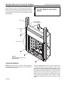
SECURe FIREPLACE to floor or framing
NOTE
The fireplace must be secured to the floor and/or to framing
studs as shown in Figure 6. Use two (2) wood screws or
masonry/ concrete screws to secure fireplace to the floor.
Use four (4) screws to attach fireplace to framing. The side
nailing flanges are 1/2" or 5/8" to accommodate different
wall thickness.
MLDV Series Gas Fireplace
DO NOT REMOVE INSULATION
BOARD
Framing
Insulation Board
DO NOT REMOVE
Screws
Nailing Flange
Figure 6 Secure Fireplace to Floor and
Framing Studs
fp1989
Finishing Material
NOTE: Any remote wiring (i.e. remote control, wall switch,
and optional fan) must be done prior to final finishing to
avoid costly reconstruction.
75D0004
Only noncombustible materials (i.e. brick, tile, slate, steel,
or other materials with a UL fire rating of Zero) may be
FP1989
used to cover the black painted face of the appliance. It is
install
fireplace
permissible
to bring combustible wall board to the top and
side edges of the black painted face. A 300°F minimum
adhesive may be used to attach facing materials to the
black surface. If joints between the finished wall and the
fireplace surround are sealed, a 300°F minimum sealant
material (General Electric RTV103 or equivalent) must be
used.
VENTING INSTALLATION
MLDV Series Gas Fireplace
NOTICE
WARNING
Venting installation
Read all instructions completely and
thoroughly before attempting installation.
Failure to do so could result in serious injury,
property damage or loss of life. Operation
of improperly installed and maintained
venting system could result in serious injury,
property damage or loss of life.
installation precautions
Consult local building codes before beginning the
installation. The installer must make sure to select the
proper vent system for installation. Before installing vent
kit, the installer must read this fireplace manual and vent
kit instructions.
Only a qualified installer/service person should install venting system. The installer must follow these safety rules:
• Wear gloves and safety glasses for protection.
• Use extreme caution when using ladders or when on
rooftops.
Failure to follow these instructions
will void the warranty.
• Be aware of electrical wiring locations in walls and
ceilings.
The following actions will void the warranty on your venting system:
• Installation of any damaged venting component.
• Unauthorized modification of the venting system.
• Installation of any component part not manufactured
or approved by Vermont Castings Group.
• Installation other than permitted by these instructions.
10
75D0004
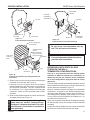
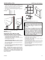
Venting installation
MLDV Series Gas Fireplace
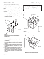
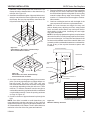
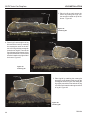
The appliance is shipped as a rear vent unit. If the installation layout requires the unit to be a top vent configuration,
the appliance can be converted by following the steps
below.
When removing and refitting the plates and adapter, be
sure the associated gaskets are undamaged and refitted
as required.
WARNING
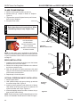
OPTIONAL TOP VENT APPLICATION
After conversion to top vent configuration,
the 5" (127 mm) flue pipe should be
concentric with the 8" (203 mm) outer collar
within 1/4".
1. Remove the eight (8) screws securing the flue pipe
adapter to the fireplace body. Figure 7
2. Set the flue pipe adapter aside, complete with the
gasket. Do not damage the gaskets as the adapter and
gasket must be refitted.
Flue Cover
Screws
Screws
Flue Pipe
Cover
Flue Pipe
Figure 8 Remove Flue Pipe
Flue Pipe
Adapter
FP1992
FP1991
Figure 7 Remove 16 screws from Flue Pipe Adapter and
Flue Pipe Cover
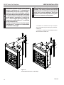
3. Remove the eight (8) screws securing the flue pipe cover
to the top of the intake box and remove the cover and
gasket. Figure
7
FP1991
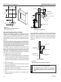
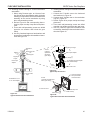
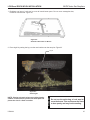
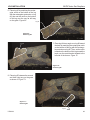
4. Remove six
(6) screws
remove
screwssecuring the flue pipe to the
back of the intake box and remove the pipe and gasket.
Figure 8
5. Replace the flue pipe to top of firebox. Ensure the gasket
is in place and undamaged. Secure with six (6) screws.
Figure 9
6. Place the flue pipe cover and gasket removed in Step
3 over the flue opening in bottom of the intake box.
7. Refit the flue pipe adapter and gasket to the top of fireplace. Secure the adapter with six (6) screws removed
in Step 1.
Flue Pipe
Screws
FP1992
remove flue pipe
FP1993
Figure 9 Attach Flue Pipe to Top Vent Configuration
11
75D0004
FP1993
replace flue pipe
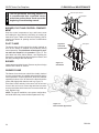
Venting installation
Horizontal sections of this vent system
require a minimum of 3” clearances to
combustibles at the top of the flue and 1”
clearance at the sides and bottom until the
flue penetrates the outside wall. A minimum
1” clearance all around the flue is acceptable
at this point of penetration. If vertical rise
is 7Z\x” feet or higher when top venting, the
clearance to combustibles is 1” on all sides
of the horizontal run.
WARNING
WARNING
MLDV Series Gas Fireplace
Vertical sections of this vent system require
a minimum of 1” clearance to combustibles
on all sides of the pipe.
This fireplace must be vented to the
outside. The venting system must NEVER
be attached to a chimney serving a separate
solid fuel burning appliance. Each gas
appliance must use a separate vent system.
Do not use common vent systems.
* A minimum of 3" clearance to the top is required
along horizontal length until flue pipe penetrates
outside wall.
** A minimum 1" clearance to combustibles permitted
all around flue at outside wall
*3”
**1”
**1”
*3”
**1”
**1”
FP1990
Figure 10 Combustible Clearances for Vent Pipe
fP1990
vent pipe clearances
12
75D0004
WARNING
Venting installation
Read all instructions completely and
thoroughly before attempting installation.
Failure to do so could result in serious injury,
property damage or loss of life. Operation
of improperly installed and maintained
venting system could result in serious injury,
property damage or loss of life.
INSTALLATION PLANNING
There are two basic types of direct-vent installation:
• Horizontal Termination
• Vertical Termination
It is important to select the proper length of vent pipe for
the type of termination you choose. It is also important to
note the wall thickness.
MLDV Series Gas Fireplace
For two-story applications, firestops are required at each
floor level. If an offset is needed in the attic, additional pipe
and elbows will be required.
You may use a chase with a vent termination with exposed
pipe on the exterior of the house. Refer to Installing Vent
System in a Chase below. If pipe is enclosed in chase, it
is not exposed.
It is very important that the venting system maintain its balance between the combustion air intake and the flue gas
exhaust. Certain limitations apply to vent configurations
and must be strictly followed.
Installing a vent system in an
outside chase
A chase is a vertical boxlike structure built to enclose
venting that runs along the outside of a building. A chase
is required for such venting.
Select the amount of vertical rise desired. All horizontal run
of venting must have 1/4" rise for every 12" of run towards
the termination below 71/2 feet of vertical rise. With 71/2 feet
or more vertical rise off top of fireplace, the horizontal run
may run level. NEVER run vent piping downward.
You may use up to three 90° elbows in this vent configuration. Refer to Horizontal Termination Configurations on
Pages 17 and 18.
NOTICE
for horizontal termination
For vertical termination
WARNING
WARNING
NOTE: You may use two 45° elbows in place of a 90° elbow.
You must follow rise to run ratios when using 45° elbows.
The appliance is approved for use with three 90° elbows
maximum or a combination of 90° and 45° elbows up to a
maximum of 270°.
Never run the vent pipe down. This may
cause excessive temperatures which could
cause a fire.
WARNING
Measure the distance from the fireplace floor to the ceiling. Add the ceiling thickness, the vertical rise in an attic
or second story, and allow for sufficient vent height above
the roof line.
When installing in a chase, you should
insulate the chase as you would the outside
walls of your home. This is especially
important in cold climates. Insulation should
be considered a combustible material.
Maintain proper clearances to all combustible
materials.
Always maintain minimum clearances
around vent systems. The minimum
clearance to combustibles for horizontal
vent pipe are 3” at the top and 1” at the
sides and bottom of the vent system until
the pipe penetrates the nearest vertical
wall (1” required). A 1” minimum clearance
all around the pipe must be maintained at
outside wall and on vertical runs. Do not
pack the open air spaces with insulation
or other materials. This could cause high
temperatures and may present a fire
hazard.
*Unless the vertical run is 7Z\x feet or higher
(top vent units only), the clearances for the
horizontal run is 1” at the top.
Treatment of firestops and construction of
the chase may vary from building type to
building type. These instructions are not
substitutes for the requirements of local
building codes. You must follow all local
building codes.
75D0004
13
venting installation
MLDV Series Gas Fireplace
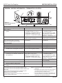
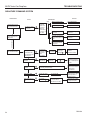
General Venting Information - Termination Location
INSIDE CORNER DETAIL G V H A D L V E C V B F Figure 11 Horizontal Vent Termination Locations
B Fixed
Closed
Ope
rable
V B V B Operable
B B J X
X AIR SUPPLY INLET V K X AREA WHERE TERMINAL IS NOT PERMITTED Canadian Installations1
CFM145a DV Termin Location 5/01/01 Rev. 12/05/01 sta M I A CFM145a V VENT TERMINATION V V Fixed
Closed
US Installations2
A = Clearance above grade, veranda, porch, 12” (30 cm)
12” (30 cm)
deck, or balcony
B = Clearance to window or door that may be 6” (15 cm) for appliances 6” (15 cm) for appliances
opened
< 10,000BTU/h (3kW), 12” (30 cm) < 10,000 BTU/h (3kW), 9”
for appliances > 10,000 Btuh (3kW) and
(23 cm) for appliances > 10,000
< 100,000 BTU/h (30kW), 36” (91 cm)
Btuh (3kW) and < 50,000 BTU/h
for appliances > 100,000 BTU/h (30kW)
(15kW), 12” (30 cm) for
appliances > 50,000 BTU/h(15kW)
C = Clearance to permanently closed window
12” (305 mm) recommended to
12” (305 mm) recommended to prevent window condensation
prevent window condensation
D = Vertical clearance to ventilated soffit located
above the terminal within a horizontal 18” (458 mm)
18” (458 mm)
distance of 2’ (610mm) from the center
line of the terminal
E = Clearance to unventilated soffit
12” (305 mm)
12” (305 mm)
F = Clearance to outside corner see next page
see next page
G =Clearance to inside corner (see next page) see next page
see next page
H = Clearance to each inside of center line
3’ (91 cm) within a height of 15’ (5 m) 3’ (91 cm) within a height of 15’
extended above meter/regulator assembly
above the meter/regulator assembly
(5 m) above the meter/regulator
assy
I = Clearance to service regulator vent outlet
3’ (91 cm)
3’ (91 cm)
J = Clearance to nonmechanical air supply inlet 6” (15 cm) for appliances < 10,000
6” (15 cm) for appliances
to building or the combustion air inlet to any BTU/h (3kW), 12” (30 cm) for
< 10,000 BTU/h (3kW), 9”
other appliances
appliances > 10,000 BTU/h (3kW) and (23 cm) for appliances > 10,000
< 100,000 Btuh (30kW), 36” (91 cm)
BTU/h (3kW) and < 50,000 BTU/h
for appliances > 100,000 BTU/h (30kW)
(15kW), 12” (30 cm) for appliances > 50,000 BTU/h(15kW)
K = Clearance to a mechanical air supply inlet
6’ (1.83 m)
3’ (91 cm) above if within 10'
(3 m) horizontally
L = Clearance above paved sidewalk or paved 7’ (2.13 m)† 7’ (2.13 m)†
driveway located on public property
M =Clearance under veranda, porch, deck or
12” (30 cm) 12” (30cm)
balcony
1 In accordance with the current CSA-B149 Installation Codes
2 In accordance with the current ANSI Z223.1/NFPA 54 National Fuel
Gas Codes
† A vent shall not terminate directly above a sidewalk or paved
driveway which is located between two single family dwellings and serves both dwellings
only permitted if veranda, porch, deck or balcony is fully open on a
minimum 2 sides beneath the floor:
14
NOTE: 1. Local codes or regulations may require different clearances.
2. The special venting system used on Direct Vent Fireplaces are certified as part of the appliance, with clearances tested and approved by the listing agency.
3. Vermont Castings Group assumes no responsibility for the improper performance of the appliance when the venting system does not meet these requirements.
75D0004
venting installation
MLDV Series Gas Fireplace
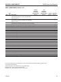
Termination Clearances
Termination clearances for buildings with combustible and noncombustible exteriors.
Alcove Applications*
Inside Corner
Outside Corner
G=
Combustible
6" (152 mm)
G
Noncombustible
2" (51 mm)
V
F=
Combustible
6" (152 mm)
Noncombustible
2" (51 mm)
V
C
V
E
O
F
Balcony with perpendicular side wall
Balcony with no side wall
D
C
E = Min. 2” (51 mm) for
non-vinyl sidewalls
Min. 12” (305 mm) for
vinyl sidewalls
O = 8’ (2.4 m) Min.
Figure 12 Allowable
Venting
M
M
V
No.
of Caps DMin. CMax.
1
3’ (914 mm)2 x DActual
2
6’ (1.8 m)
1 x DActual
3
9’ (2.7 m)2/3 x DActual
4
12’ (3.7 m) 1/2 x DActual
V
P
M=
Combustible &
Noncombustible
12" (305 mm)
Combustible &
Noncombustible
M = 12" (305 mm)
P = 6” (152 mm)
584-15
DMin. = # of Termination caps x 3
CMax. = (2 / # termination caps) x DActual
*NOTE: Termination in an alcove space (spaces open only on one side and with an overhang) is permitted with the dimensions specified for vinyl or
non-vinyl siding and soffits. 1. There must be a 3’ (914 mm) minimum between termination caps. 2. All mechanical air intakes within 10’ (1 m) of a
termination cap must be a minimum of 3’ (914 mm) below the termination cap. 3. All gravity air intakes within 3’ (914 mm) of a termination cap must
be a minimum of 1’ (305 mm) below the termination cap.
How To Use The Vent Graph
1. Determine the height of the center of the horizontal vent
pipe exiting through the outer wall. Using this dimension on the Sidewall Vent Graph below, locate the point
intersecting with the slanted graph line.
2. From the point of this intersection, draw a vertical line
to the bottom of the graph.
3. Select the indicated dimension, and position the fireplace in accordance with same.
Example: If the vertical dimension from the floor of the
fireplace is 11' (3.4 m) the horizontal run to the face of
the outer wall must not exceed 14' (4.3 m).
Example: If the vertical dimension from the floor of the
unit is 7’ (2.14 m), the horizontal run to the face of the
outer wall must not exceed 7' (2.1 m).
Sidewall Vent Graph showing the relationship between
vertical and horizontal dimensions for a Direct Vent flue
system.
75D0004
Vertical Dimension From the Floor of Unit to the
Center of the Horizontal Vent Pipe
The Vent Graph should be read in conjunction with the
following vent installation instructions to determine the
relationship between the vertical and horizontal dimensions
of the vent system.
40
38
36
34
32
30
28
26
24
22
20
18
16
14
12
10
8
6
4
2
Dimensions in
Feet
eg: A
2 4 6 8 10 12 14 16 18 20
Horizontal dimension from the finished outside wall
to the center of the pipe on the fireplace
Figure 13 Rear Wall Venting Graph
FP1952
sidewall vent graph
15
MLDV Series Gas Fireplace
REAR WALL VENT INSTALLATION (5" x 8"
VENTING ONLY)
When installed as a rear vent unit, this appliance may be
vented directly to a termination located on the rear wall
behind the appliance. Only an Vermont Castings Group
brand termination is allowed for this application.
• The maximum horizontal distance between the rear
of the appliance and the termination is 20" (508 mm).
Figure 14
Maximum
20"
venting installation
2. Refer to venting and termination instructions for further
instructions.
3. Locate and cut the vent opening in the wall. For combustible walls first frame in opening.
Combustible Interior Walls: Cut a 121/2" x 101/2" hole
through the interior wall.
Combustible Exterior Walls: Cut a 101/2" x 101/2"
square hole through the exterior wall frame. Figure 16
Noncombustible Walls: Hole opening should be 81/2"
(216 mm) in diameter.
4. The center of the hole should align with the center line
of the horizontal rigid vent pipe end. Allow 1/4" minimum
rise per foot. Figure 16
101/2"
(267 mm)
Top View Flat Installation
Figure 14 - Rear Vent Application,
Maximum
Horizontal Distance
DVR584-600
101/2"
(267 mm)
vent no elbows
• Only one 45Rear
degree elbow is allowed in these installa2/99 djt
tions.
1. Rigid vent pipes and fittings have special twist-lock
connections. Assemble the desired combination of pipe
and elbows to the appliance adapter.
Twist-Lock Procedure: The female ends of the pipes
and fittings have three (3) locking lugs (indentations).
These lugs will slide straight into matching slots on
the male end of adjacent pipes and fittings. Push the
pipe sections together and twist one section clockwise
approximately one-quarter turn until the sections are
fully locked. Figure 15
NOTE: Sealant is not required to assemble fireplace
venting. Do not use silicone sealant at the inner flue
exhaust connections.
Female Locking
Lugs
NOTE: Horizontal runs of
vent must be supported every
three feet (914 mm). Use wall
straps for this purpose.
Male Slots
Figure 15 Rigid Vent Pipe Connections
16
Combustible Wall
81/2"
(216 mm)
Noncombustible
Wall
FP1954
Figure 16 - FP1954
framing
Exterior Wallwall
Framing
Dimensions
5. Apply a bead of non-hardening mastic around the
outside edge of vent cap. Position the vent cap in the
center of hole on the exterior wall with the word "UP"
on the vent cap facing up. Insure proper clearance of
1" to combustibles is maintained. Attach the vent cap
with four (4) wood screws supplied. Figure 17
NOTE: Replace the wood screws with appropriate
fasteners for stucco, brick, concrete or other types
of siding.
For vinyl siding, stucco or wood exterior, use vinyl
siding standoffs between vent cap and exterior wall for
Duravent or Selkirk Terminations only. The vinyl siding
standoff prevents excessive heat from melting the
vinyl siding material. NOTE: Vermont Castings Group
Termination does not require standoff. Bolt the vent
cap to the standoff or wall. Apply non-hardening mastic
around outside edge of the standoff instead of the vent
cap assembly. Use wood screws provided to attach the
standoff. Figure 18
75D0004
venting installation
MLDV Series Gas Fireplace
Inerior Wall
Surface
Vent Cap
(Horizontal
Termination)
Vent Cap
Firestop
T
HO
Apply Mastic to all
Four Sides
FP1957
Wood Screw
Screw
Figure 17 Install Horizontal Termination
T
HO
FP1956
Nut
Bolt
Wood Screw
Figure 18 Install Duravent/Selkirk Vinyl Siding Standoff and
Termination
notice
6. Slide the stop
over the vent pipe before connecting the
FP1956
horizontal run to the vent cap. Figure 19
vinyl siding
7. Carefully move the fireplace with vent assembly
attached toward the wall and insert the vent pipe into
the horizontal termination. The pipe overlap should
be a minimum of 11/4". Apply silicone to the outer pipe
connection. Fasten all vent connections with screws
provided.
8. Slide the wall thimble against the interior wall surface
and attach with screws. Figure 19
All rear vent through-the-wall applications must use Vermont Castings Groupdesigned 5 x 8 square termination. No other
manufacturer's termination is permitted in
this application.
75D0004
NOTICE
Apply Mastic
to all Four
Sides
Standoff #1250 or
5DT-VS
(Not required for
Vermont Castings
Group termination)
Termination
WARNING
Figure 19 Install Firestop on Horizontal Vent Pipe
Cut Vinyl Siding Away
to Fit Standoff
FP1955
horizontal vent cap
Horizontal
Vent Pipe
FP1957
vent cap w hor pipe
Do not recess vent termination into any
wall. This will cause a fire hazard.
For more information, follow instructions
provided with terminations.
HORIZONTAL WITH VERTICAL RISE
(THROUGH-THE-WALL)
TERMINATION CONFIGURATIONS
Since it is very important that the venting system
maintain its balance between the combustion air
intake and the flue gas exhaust, certain limitations
as to vent configurations apply and must be strictly
adhered to.
The Vent Graph, showing the relationship between vertical
and horizontal side wall venting, will help to determine the
various dimensions allowable. Figure 13
Minimum clearance between vent pipes and combustible
materials is 3" on top and 1" from bottom and sides unless
otherwise noted (Exception: Outside wall with firestop: 1"
all around pipes are allowed). If the vertical run is 71/2 feet
or more, off the top of the fireplace, the clearance is 1" on
all sides of the horizontal run.
When vent termination exits through foundations less than
20" below siding outcrop, the vent pipe must be flush with
the siding.
It is best to locate the fireplace in such a way that minimizes
the number of offsets and horizontal vent length.
17
venting installation
MLDV Series Gas Fireplace
The horizontal vent run refers to the total length of vent
pipe from the flue collar of the fireplace (or the top of the
Transition Elbow) to the face of the finished outside wall
or the mounting flange of the termination.
• The maximum number of 90° elbows per side wall
installation is three (3). Figure 20
• If a 90° elbow is fitted directly on the top of the fireplace,
the maximum horizontal vent run before the termination
or a vertical rise is 36” (914 mm). Figure 21
3 x 90°
Elbows
• If a 90° elbow is used in the horizontal vent run (level
height maintained) the horizontal vent length is reduced
by 36". Figure 23. This does not apply if the 90° elbows
are used to increase or redirect a vertical rise. Figure
22
Example: According to the vent graph (Page 17) the
maximum horizontal vent length in a system with a 7.5'
vertical rise is 20’ (6 m) and if a 90° elbow is required in the
horizontal vent it must be reduced to 17' (5.2 m).
In Figures 22 and 23 dimension A plus B must not be
greater than 17' (5.2 m).
90°
A
B
3 x 90°
Elbows
Figure 20 Maximum Three (3) 90° Elbows
Per Installation
7'6"
FP1176
36"
(914FP1176
mm)
Max.
FP1958
36"
(914 mm)
Max.
max 90 bends
Figure 22 Horizontal Run Reduction
A
10'
FP1958
Horizontal run reduction
FP1177
7'
B
WARNING
Figure 21 Maximum Horizontal Run with No Rise
When installing the appliance as a rear
vent unit, the 90° or 45° transition elbow
attached directly to the rear of the unit is
NOT INCLUDED in the following criteria
and calculations and, unless specifically
mentioned, should be ignored when
calculating venting layouts.
Horizontal 90° Elbow = 3' Reduction
7'6"
A + B = 17' Maximum
Figure 23 Maximum Vent Run with Elbows
Max 20"
18
FP1959
75D0004
venting installation
MLDV Series Gas Fireplace
• For each 45° elbow installed in the horizontal run, the
length of the horizontal run MUST be reduced by 18"
(457 mm). This does not apply if the 45° elbows are
installed on the vertical part of the vent system.
• The maximum number of elbow degrees in a system is
270°. Figure 24
Example:
Elbow 1 = 90°
Elbow 2 = 45°
Elbow 3 = 45°
Elbow 4 = 90°
Total Angular Variation = 270°
101/2"
(267 mm)
101/2"
(267 mm)
Combustible
Wall
81/2"
(216 mm)
1
Noncombustible
Wall
1
2
Figure 25 FP1954Dimensions for 5" x 8"
Exterior Wall Framing
wall framing
2
3
3
4
FP1180
Figure 24 Maximum Elbow Usage
Horizontal with vertical rise
(through-the-wall) applications
1. Locate and cut the vent opening in the wall. For
combustible walls first frame in opening.
Combustible Interior Walls: Cut a 12Z\x"H x 10Z\x" W
hole through the interior wall.
Combustible Exterior Walls: Cut a 10Z\x"H x 10Z\x"W
square hole through the exterior wall frame. Figure 25
Noncombustible Walls: Hole opening should be 8Z\x"
(216 mm) in diameter.
2. The center of the hole should line up with the center line
of the horizontal rigid vent pipe end. Allow 1/4" minimum
rise per foot. Figure 25
WARNING
4
1 + 2 + 3 + 4 = 270°
FP1954
You may use a reducer from 5" x 8" to 4" x
6B\," or 4" x 7" for horizontal with vertical rise
applications. ONLY use framing instructions
below when using 4" x 6B\," or 4" x 7"
venting.
If the reducer is installed at the rear of the
unit, you must immediately follow with a 90
elbow for a vertical rise before continuing
with any horizontal run. There is a minimum
total height of 7 feet from the fireplace floor
to the last section of pipe before horizontal
run. Refer to graph on Page 17.
1. Locate and cut the vent opening in the wall. For combustible walls first frame in opening.
Combustible Interior Walls: Cut a 11Z\x"H x 9Z\x" W
hole through the interior wall.
Combustible Exterior Walls: Cut a 9Z\x"H x 9Z\x"W
square hole through the exterior wall frame. Figure 26
Noncombustible Walls: Hole opening should be 7Z\x"
(190 mm) in diameter.
2. The center of the hole should line up with the center line
of the horizontal rigid vent pipe end. Allow 1/4" minimum
rise per foot. Figure 26
NOTE: #1222DA reducer must be used when 4x6B\,"
venting is preferred. The 7TDVP58 reducer must be
used when 4" x 7" venting is preferred. Reducer must
be installed directly onto unit at the fireplace collar
before vertical rise.
75D0004
19
venting installation
MLDV Series Gas Fireplace
91/2"
(241 mm)
Screws
Firestop
Minimum
4" Clearance
Ground
91/2"
(241 mm)
Window Well
12"
Minimum
Combustible
Wall
Gravel
Drain
71/2"
(190 mm)
Noncombustible
Wall
Foundation Wall
FP1954
Figure 26 FP1954 Dimensions
Exterior Wall Framing
for 4" x 65/8" orwall
4" framing
x 7"
Below Grade Installations
When it is not possible to meet the required vent terminal
clearances of 12" above grade level, a snorkel kit is recommended. It allows installation depth down to 7" (178 mm)
below grade level. The 7" (178 mm) is measured from the
center of the horizontal vent pipe as it penetrates through
the wall.
FP1965
Figure 27 Below Grade Installation
FP1965
below
grade install
If the foundation
is recessed,
use recess brackets (not
supplied) for securing lower portion of the snorkel. Fasten
brackets to wall first, then secure to snorkel with self drilling #8 x 1/2 sheet metal screws. It will be necessary to
extend vent pipes out as far as the protruding wall face.
Figure 28
Ensure that sidewall venting clearances are observed.
If venting system is installed below ground, we recommend a window well with adequate and proper drainage
to be installed around the termination area.
Snorkel
If installing a snorkel, a minimum 24" vertical rise is necessary. The maximum horizontal run with the 24” vertical
pipe is 36". This measurement is taken from the collar of
the fireplace (or transition elbow) to the face of the exterior
wall. Refer to the Sidewall Venting Graph for extended
horizontal run if the vertical exceeds 24".
20
Wall Screws
Watertight Seal
Around Pipe
Sheet Metal
Screws
FP1966
Figure 28 Snorkel Installation, Recessed Foundation
WARNING
1. Establish vent hole through the wall.
2. Remove soil to a depth of approximately 16" below base
of snorkel. Install drain pipe. Install window well (not
supplied). Refill hole with 12" of coarse gravel leaving
a clearance of approximately 4" below snorkel. Figure
27
3. Install vent system.
4. Ensure a watertight seal is made around the vent pipe
coming through the wall.
5. Apply high temperature sealant caulking (supplied)
around the 5" and 8" snorkel collars.
6. Slide the snorkel into the vent pipes and secure to the
wall.
7. Level the soil so as to maintain a 4" clearance below
snorkel. Figure 27
Foundation
Recess
FP1966
snorkel
• Do not back fill around snorkel.
• A clearance of at least 4” must be
maintained between the snorkel and the
soil.
75D0004
venting installation
MLDV Series Gas Fireplace
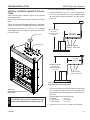
VERTICAL THROUGH-THE-ROOF APPLICATIONS
Install restrictor disc as shown in Figure 29 for vertically
vented applications.
Up to two (2) restrictor discs may be needed for 40' installation.
This Gas Fireplace has been approved for,
• Vertical installations up to 40' (12 m) in height. Up to
a 10' (3 m) horizontal vent run can be installed within
the vent system using a maximum of two 90° elbows.
Figure 30
The two (2) restrictor discs suppled will work for most installations. If a third disc is needed order Part No. 56D3027.
You may use a reducer to 4" x 6B\," or 4" x 7" in vertically
vented applications. If a reducer is used, only one restrictor may be used.
Restrictor Disc
Maximum Height
40' (12 m)
Minimum Height
8' (2 m)
Fireplace Collar
10' (3 m)
Maximum
Support Straps
Every 3' (914 mm)
10' (3 m)
Maximum
Maximum Height
40' (12 m)
Minimum Height
8' (2 m)
FP1183
max height
Support Straps
Every 3' (914 mm)
FP1183
Figure 30 Support Straps for Horizontal Runs
NOTICE
Figure 29 Install Restrictor Disc into Fireplace Collar
• Up to two 45° elbows may be used within the horizontal
FP1183 FP1967
max height
A restrictor disc must be installed on any
vertical termination that is higher than 12'.
FP1967
restrictor disc
75D0004
run. For each 45° elbow used on the horizontal plane,
the maximum horizontal length must be reduced by 18"
(450 mm).
Example: Maximum horizontal length
No elbows = 10’ (3 m)
1 x 45° elbows = 8.5’ (2.6 m)
2 x 45° elbows = 7’ (2.1 m)
• A minimum of an 8' (2.5 m) vertical rise is required.
21
venting installation
MLDV Series Gas Fireplace
• Two sets of 45°elbows offsets may be used within the
vertical sections. From 0 to a maximum of 8' (2.5 m) of
vent pipe can be used between elbows. Figure 31
• Determine the roof pitch and use the appropriate starter
kit for offset installation.
• The maximum angular variation allowed in the system
is 270°. Figure 31
• For the minimum height of the vent above the highest
point of penetration through the roof refer to Page 25,
Figure 35.
1
INSTALLATION FOR VERTICAL
TERMINATION
1. Determine the route your vertical venting will take. If
ceiling joist, roof rafters or other framing will obstruct
the venting system, consider an offset. Refer to Figure
32 to avoid cutting load bearing members.
NOTE: Pay special attention to these installation instructions
for required clearances (air space) to combustibles when
passing through ceilings, walls, roofs, enclosures, attic
rafters, etc. Do not pack air spaces with insulation. Also
note maximum vertical rise of the venting system and any
maximum horizontal offset limitations. Offsets must fall
within the parameters shown on Page 17, Figure 13.
2
3
Roof
Flashing
4
Wall Strap
1
2
Example:
Elbow 1 = 90°
Elbow 2 = 45°
Elbow 3 = 45°
Elbow 4 = 90°
Total Angular Variation = 270°
45° Elbows
3
4
FP1669
Ceiling Firstop
Figure 31 Maximum Elbow Usage
FP1179
max bends
FP1179
Figure 32 Offset with Wall Strap and 45° Elbows
FP1969location. Drop a plumb line down
2. Set fireplace in desired
wallstrap
from the ceilingoffset
to thew/
position
of the flue exit. Mark the
center point where the vent will penetrate the ceiling.
Drill a small locating hole at this point.
Drop a plumb line from the inside of the roof to the locating hole in the ceiling. Mark the center point where the
vent will penetrate the roof. Drill a small locating hole
at this point.
flat ceiling installation
1. Cut a 10Z\x" (267 mm) square hole in the ceiling using
the locating hole as a center point The opening should
be framed to 10Z\x" x 10Z\x" (267 x 267 mm) inside
dimensions as shown in Figure 33 using framing lumber
the same size as the ceiling joist. If the area above the
ceiling is an insulated ceiling or a room, nail firestop
from the top side. This prevents loose insulation from
falling into the required clearance space. Figure 34.
22
75D0004
venting installation
MLDV Series Gas Fireplace
Otherwise, install firestop below the framed hole. The
firestop should be installed with no less than three (3)
nails per side. Figure 34.
2. Assemble the desired lengths of pipe and elbows necessary to reach from the burner system flue up through
the firestop. Be sure pipe and elbow connections are
fully twist-locked. Page 18, Figure 15.
10
/"
1 2
101
/2"
FP1970
Nails
Firestop
Figure 33 If Area Above is Not a Room, Install Firestop
above Framed Hole as Shown
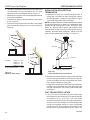
5. Place the flashing over the pipe section(s) extending
through the roof. Secure the base of the flashing to
the roof and framing with roofing nails. Be sure roofing
material overlaps the top edge of the flashing. There
must be a 1" clearance from the vent pipe to combustible materials.
6. Continue to add pipe sections until the height of the
vent cap meets the minimum requirements below.
NOTE: You must increase vent height for steep roof
pitches. Nearby trees, adjoining roof lines, steep pitched
roofs, and other similar factors may cause poor draft or
down-drafting in high winds. Increasing the vent height
may solve this problem.
NOTE: If the vent pipe passes through any occupied areas
above the first floor, including storage spaces and closets,
you must enclose pipe. You may frame and sheetrock the
enclosure with standard construction material. Make sure
to meet the minimum allowable clearances to combustibles.
Do not fill any of the required clearance spaces with
insulation. Horizontal Overhang
Nails
2 ft.
Min.
FP1970
firestop no room
Vertical Wall
2 ft. Min.
Lowest
Discharge
Opening
Termination
Vent
H*
12
X
Storm Collar
Firestop
FP1969
Figure 34 If Area Above is a Room, Install Firestop
above Framed Hole as Shown
3. Cut a hole in the roof using the locating hole as a center
point. (Cover any exposed open vent pipes before cutting hole in roof).
The 10Z\x" x 10Z\x" (267 x 267 mm)
FP1969
hole must be measured on the horizontal. Actual length
firestop w room above
may be larger depending on the pitch of the roof. There
must be a 1" minimum clearance from the vent pipe to
combustible materials. (Insulation should be considered
a combustible material). Frame the opening as shown
on Page 18, Figure 16.
4. Connect a section of pipe and extend up through the
hole.
NOTE: If an offset is needed to avoid obstructions, you
must support the vent pipe every three (3) feet. Use wall
straps for this purpose. Figure 32. Whenever possible, use
45° elbows instead of 90° elbows. The 45° elbow offers less
restriction to the flow of the flue gases and intake air.
75D0004
FP1971
Flashing
1" Minimum Clearance to
Combustibles
Concentric
Vent Pipe
Roof Pitch
H (feet)
Flat to 6/12
1.0
Over 6/12 to 7/12
1.25
Over 7/12 to 8/12
1.5
Over 8/12 to 9/122.0
FP1971
Overclearance
9/12 to 10/122.5
Min chimney
Over 10/12 to 11/12
3.25
Over 11/12 to 12/12
4.0
*H - Minimum height from roof to
lowest discharge opening of vent
Figure 35 Minimum Chimney Clearance
23
Flex vent installation
MLDV Series Gas Fireplace
1. Flexible UL1777 listed venting may be used in any
venting application where rigid direct vent components
can be used. All restrictions, clearances and allowances that pertain to the rigid piping apply to the
flexible venting. Flex kits may not be modified. Flex
kits may be added to the end of a vent run made of rigid
vent sections using pipe manufacturer's approved flex
to pipe adapters. This may occur only if doing so does
not violate any of the venting length, height, routing,
horizontal to vertical ratio requirements or clearance
considerations detailed in this manual.
5" x 8" Flex Vent Pipe
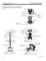
2. The flex adapter starter kit (DVFF8A/8) is used to attach
flex venting to the appliance starting collar. It includes
5" inner and 8" outer adapter rings. Figure 36
• The inner and outer adapter rings are required to
start all flex runs.
• Never install damaged or torn flexible venting.
• Over tightening clamps may rip, tear, or otherwise
damage flexible venting.
• The adapter kit does not include individual pipe sections which may be purchased separately. (UL1777
listed type venting only.)
3. Start the flexible vent as follows:
A. Installing the inner flex adapter and pipe. Figure 36
UL1777
Flex Vent
1C\v" Flexible
Pipe and Adapter
Outer
Pipe
Clamps
DVFF8A/8
Inner Adapter
Outer Adapter
Screws
(3 places,
equidistant just
above gear
clamp)
Appliance
Starting Collar
FP1972
NOTE
Figure 36 Typical Appliance Connection
24
F l e x v eFP1972
nt pipe spacers: Refer to
manufacturer’s
specifications
appliance
connection for correct
positioning of the spacer springs to
maintain proper distance between inside
and outside pipe.
1. Insert the long side of the 5" inner ring into
exhaust pipe, gently tap to seat into place, and
secure with screws.
2. Slide the small gear clamp over the inner flexible
vent pipe, and push out of the way.
3. Pull and extend the inner flexible vent.
4. Slide the inner vent onto the adapter collar, for a
minimum 1C\v" overlap.
5. Locate the clamp at approximately 3/4" from the
flex end and tighten.
6. Secure the clamped inner section with three selftapping screws, drilled equidistant, just above the
clamp perimeter.
B. Installing the outer flex pipe. Figure 36
1. Firmly insert the 8" outer adapter ring into the
outer appliance starting collar and secure with
screws.
2. Slide the large gear clamp over the outer flexible
vent pipe, and push out of the way.
3. Pull and extend the outer flexible vent.
4. Slide the outer vent onto the appliance collar outer
adapter for a minimum 1C\v" overlap.
5. Locate the clamp at approximately 3/4" from the
flex end and tighten.
6. Secure the clamped outer section with three selftapping screws, drilled equidistant, just above the
clamp perimeter.
C.Routing UL1777 flex pipe.
1. Always maintain the required clearance when
routing the flex vent assembly.
2. Install firestop spacers, Figure 38, when penetrating ceiling, attic spaces, or walls.
3. Do not allow the flexible vent to bend in radius
tighter than 5" (127 mm). Figure 37
4. Horizontal runs UL1777
of flexible vent Flex Vent
shall be supported at maximum 2 foot
intervals; vertical runs, five
5° Radius
feet intervals.
Metal strapFP1973
ping, properly
secured, is an Figure 37 a c c e p t a b l e Minimum Radius for Flex
means to sup- Vent Section
FP1973
port the flexible
flex pipe bend
vent.
5. Flexible vent spacers are to be installed at intervals prescribed by the flexible vent manufacturer;
and in such a way as to maintain concentric inner
and outer vent spacing.
75D0004
flex vent installation
MLDV Series Gas Fireplace
D.Attaching flexible venting to vertical termination
assemblies.
1. When using Duravent pipe, an Vermont Castings Group flex-to-pipe adapter and/or rigid pipe
section(s) is required to connect the flexible vent
assembly to the vertical termination by using
three self-penetrating screws.
2. Review Figure 39 and corresponding instructions for proper overlap, clamp and screw placement.
3. Three each self-penetrating screws are drilled
opposite one another and below the gear
clamp.
4. Use only listed and approved terminations and
accessories, installed per the installation instructions and Figure 38.
Termination
Cap
Flashing
Storm Collar
Roof Support
Rigid Pipe
Length
E. Installing flexible venting to horizontal termination
assemblies.
1. Connect the 5" flexible vent to the horizontal
termination as in Figure 40.
2. Connect the 8" flexible vent to the termination
ring as in Figure 40.
3. Review Figure 40 for proper overlap and clamp
placement.
4. Three each self-penetrating screws are drilled
opposite one another and below the gear lamp.
5. Use only listed an approved terminations and
accessories, installed per the termination instructions and Figure 40.
Rigid Pipe Length
Screws
(3 Places
equidistant
just above
gear clamp)
Flex to Pipe Adapter
Gear Clamp
1C\v" Flexible Pipe and Adapter
Outer Collar Overlap
Flex to Pipe
Adapter
Gear
Clamp
Firestop
UL1777 Flex Vent
Figure 39 FP1975
Typical Pipe Connection
pipe connection
UL1777 Flex
PIpe
Screws
(3 Places equidistant just
above gear clamp)
DVFF8A/8 5" x 8" to
5" x 8" Flex Adapter
UL1777 Flex Vent
FP1974
Figure 38 Typical Vertical Flex Vent Installation
75D0004
Gear Clamp
Vermont Castings
Group Horizontal
Vent Termination
1C\v" Flexible Pipe and
Collar Overlap
Figure 40 Typical Horizontal Flex Vent Installation
FP1976
horizontal flex
25
FLEX vent installation
MLDV Series Gas Fireplace
4" x 7" Flex Pipe
If you prefer to use 4" x 7" flex pipe, you must install model
7TDVP58 reducer (5" x 8" to 4" x 7") onto the fireplace
collar. Then follow the assembly guidelines for 5" x 8" flex
venting.
UL1777
Flex Vent
1C\v" Flexible Pipe and
Adapter Outer
5" x 8" to 4" x 7"
Adapter (7TDVP58)
Gear Clamp
Screws
(3 places,
equidistant just
above gear
clamp)
Appliance
Starting Collar
Figure 41 Typical 4" x 7" Appliance Connection
FP1972a
FP1972
appliance connection
Termination
Cap
Flashing
Storm Collar
Roof Support
Rigid Pipe
Length
Screws
(3 Places
equidistant
just above
gear clamp)
Flex to Pipe Adapter
(DVFFA/8)
Gear Clamp
1C\v" Flexible Pipe and Adapter
Outer Collar Overlap
Flex to Pipe
Adapter
(DVFFA/8)
Firestop
4" x 7"
Rigid Pipe Length
Gear
Clamp
UL1777 Flex Vent
Figure 43 FP1975
Typical Pipe Connection
4 x 7 pipe connection
UL1777 Flex
PIpe
Screws
(3 Places equidistant just
above gear clamp)
7TDVP58 5" x 8" to
4" x 7" Reducer
UL1777 Flex Vent
FP1974
Figure 42 Typical Vertical Flex Vent Installation
26
Gear Clamp
Vermont Castings
Group Horizontal
Vent Termination
1C\v" Flexible Pipe and
Collar Overlap
Figure 44 Typical Horizontal Flex Vent Installation
FP1976
horizontal flex
75D0004
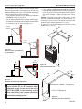
fireplace installation
MLDV Series Gas Fireplace
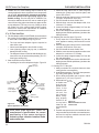
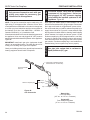
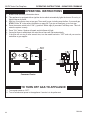
check gas type
Use proper gas type for the fireplace you are installing.
If you have conflicting gas type, do not install fireplace.
See dealer where you purchased the fireplace for proper
fireplace for your gas type or conversion kit.
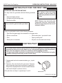
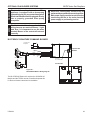
External
Regulator
100 gallon (min)
Propane/LP Supply
Tank
WARNING
Installing gas piping to fireplace /
burner system location
A qualified installer or service person must
connect appliance to gas supply. Follow
all local codes.
Vent Pointing
Down
INSTALLATION ITEMS NEEDED
•
•
•
•
•
•
•
Tee joint
• Pipe wrench
Equipment shutoff valve* • Test gauge connection*
Sediment trap (recommended)
External regulator (supplied by installer)
Piping (check local codes)
Sealant (resistant to propane/LP gas)
approved flexible gas line with gas connector (if
allowed by local codes — not provided)
* A CSA design-certified equipment shutoff valve with
1/8" NPT tap is an acceptable alternative to test gauge
connection. Purchase the CSA design-certified equipment shutoff valve from your dealer.
CAUTION
For propane/LP connections only, the installer must supply
an external regulator. The external regulator will reduce
incoming gas pressure. You must reduce incoming gas
pressure to between 11 and 13 inches of water. If you do
not reduce incoming gas pressure, burner system regulator damage could occur. Install external regulator with the
vent pointing down as shown in Figure 45. Pointing the
vent down protects it from freezing rain or sleet.
Figure 45 External Regulator with Vent Pointing Down
(Propane/LP Only)
FP1977
external regulator
CAUTION
Before installing fireplace and burner system, make sure
you have the items listed below.
Use only new black iron or steel pipe.
Internally tinned copper or copper tubing
can be used per National Fuel Code, Section
2.6.3, providing gas meets hydrogen sulfide
limits, and where permitted by local codes.
Gas piping system must be sized to provide
minimum inlet pressure (listed on data plate)
at the maximum flow rate (BTU/hr). Undue
pressure loss will occur if the pipe is too
small.
When using copper of flex connectors use only fittings
approved for gas connections. The gas control inlet is
3/8" NPT.
For propane/LP units, never connect
fireplace directly to the propane/LP supply.
This burner system requires an external
regulator (not supplied). Install the external
regulator between the burner system and
propane/LP supply.
75D0004
27
fireplace installation
Only persons licensed to work with gas
piping may make the necessary gas
connections to this appliance.
CAUTION
WARNING
MLDV Series Gas Fireplace
A manual shutoff valve must be installed
upstream of the appliance. Union tee
and plugged 1/8” NPT pressure tapping
point should be installed upstream of the
appliance. Figure 46
Apply pipe joint sealant lightly to male threads. This will
prevent excess sealant from going into pipe. Excess sealant in pipe could result in clogged burner system valves
NOTE : The gas line connection may be made using 1/2"
rigid tubing or an approved flex connector. Since some
municipalities have additional local codes it is always best
to consult your local authorities and the current edition of
the National Fuel Gas Code ANSI.Z223.1, NFPA54. In
Canada CSA-B149 (1 or 2) Installation Code.
We recommend that you install a sediment trap/drip leg in
supply line as shown in Figure 46. Locate sediment trap/
drip leg where it is within reach for cleaning. Install in piping
system between fuel supply and burner system. Locate
sediment trap/drip leg where trapped matter is not likely
to freeze. A sediment trap collects moisture and contaminants and keeps them from going into the burner system
gas controls. If sediment trap/drip leg is not installed or is
installed wrong, burner system may not run properly.
A listed manual shutoff valve must be installed upstream of
the appliance. Union tee and plugged 1/8" NPT pressure
tapping point should be installed upstream of the appliance.
Figure 46
CAUTION
IMPORTANT: Install main gas valve (equipment shutoff
valve) in an accessible location. The main gas valve is for
turning on or shutting off the gas to the fireplace.
Check your building codes for any special requirements for
locating equipment shutoff valve to fireplaces.
Use pipe joint sealant that is resistant to
liquid petroleum (LP) gas.
CSA Design-Certified Equipment
Shutoff Valve with 1/8" NPT Tap*
Approved Flexible
Gas Line
Tee Joint
Sediment Trap/Drip Leg
Pipe Nipple
Cap
Figure 46 Gas Connection
FP1978
gas connection
28
3"
Mi
nim
um
Natural Gas
From Gas Meter
(4.5" w.c. to 10.5" w.c. Pressure)
Propane/LP
From External Regulator
(11" w.c. to 13" w.c. Pressure)
75D0004
CHECK GAS PRESSURE and Electrical installation - MILLIVOLT
MLDV Series Gas Fireplace
This fireplace will work without any electrical supply. Electricity is only needed to operate blower.
WARNING
NOTE: If installed in mobile home, fireplace must be bolted
securely to floor.
Electrical connections should only
be performed by a qualified, licensed
electrician. Main power must be off when
connecting to main electrical power supply
or performing service. All wiring shall be
in compliance with all local, city and state
codes. The appliance, when installed, must
be electrically grounded in accordance with
local codes or in the absence of local codes,
with the National Electrical Code ANSI/NFPA
70 (latest edition) and Canadian Electrical
Code, CSA C22.1.
75D0004
WARNING
Electrical Wiring
Do not use open flame to check for
gas leaks.
CAUTION
1. Check gas type. The gas supply must be the same
as stated on the appliance’s rating decal. If the gas
supply is different from the fireplace, STOP! Do not
install the appliance. Contact your dealer immediately.
2. To ease installation, a 24" (610 mm) flex line with
manual shut-off valve has been provided with on
this appliance. Install and attach 1/2" gas line onto
shut-off valve.
3. After completing gas line connection, purge air from
Pressure
gas line and test all gas joints from the gas meter Test “IN”
to the fireplace for leaks. Use a solution of 50/50
water and soap solution or a gas sniffer.
Pressure
4. To adjust flame height, turn HI/LO knob to HI to get Test “OUT”
FP1979
maximum pressure to burner. Turn HI/LO knob to
HI/LO Knob
LO to get minimum pressure.
Pilot Adjustment Screw
5. To check gas pressures at valve, turn captured
screw counter clockwise 2 or 3 turns and then place
Figure 47 tubing to pressure gauge over test point. Turn unit
Gas Pressure Check at Gas Valve
to high. Figure 47 After taking pressure reading,
be sure and turn captured screw clockwise firmly
FP1979
to reseal. Do not over torque. Check test points for gas
leaks.
Millivolt gas valve
Label all wires before disconnecting when
servicing controls. Wiring errors can cause
improper and dangerous operation.
Verify proper operation after servicing.
29
REMOTE WALL SWITCH INSTALLATION
MLDV Series Gas Fireplace
A remote wall switch and up to fifteen (15) feet of 18 Ga.
wire may be used with this appliance. Attach the wall
switch in a junction box at the desired location on the
wall. Figure 48. Do not extend beyond the wall switch wire
length provided.
NOTE: Extended lengths of wire may cause the
fireplace not to function properly. Longer length of
wire is permitted if the wire is made out of larger gauge
(diameter) wire. Always check with local code.
WARNING
Remote Wall mounted Switch
Do not connect wall switch 110V circuit.
OPTIONAL REMOTE
WALL SWITCH
ON
HI
ON
OFF
PILOT
LO
TH
TP
TH/TP
ON
OFF
RS
OFF
OPTIONAL REMOTE
WALL SWITCH
Figure 48 Wiring Diagram for Wall Switch
ON
OFF
OPTIONAL FAN/BLOWER SYSTEM
(BLOTBLDV)
Installation Instructions
Wiring
FP1980
1. Before installing the blower, wire the receptacle
into an
120V AC
electrical circuit. This should be done before
framing
Dv wiring diagram
60Hz
the fireplace. Wire with minimum 60° C wire in accordance with prevailing codes.
Factory Supplied
2. Remove the external junction box cover by removing
Not Supplied
the screw from the left side of the outside firebox wall.
Junction Box
Figure 49 Junction box was installed at the factory.
Junction Box Wiring Diagram
3. The junction box cover has a factory installed “romex”
style strain relief connector. After connecting the wires,
route the wire leads through this connector. Refer to
Install the Blower
the wiring diagram in Figure 49.
FP1912
1. Remove the lower access panel by pulling up and
Before Installing the Blower
Junction
box wiring
away from
unit.
1. Always turn off the gas supply and allow the unit to
2. Remove8/08
glass frame by releasing the two (2) latches
cool down before proceeding.
(500 Model has three (3) latches) below the firebox
2. Clean the inside of the firebox (wall and floor), where
opening and lifting glass frame up and away from
the blower and wires will be installed. Make sure the
unit.
firebox wall and floor are clean and dry before mount3. Remove logs.
ing the blower.
4. Remove grate from engine by lifting up.
30
75D0004
OPTIONAL FAN/BLOWER SYSTEM
MLDV Series Gas Fireplace
5. Remove hearth brick and wall brick panels.
6. Disconnect the gas line to the valve.
7. Remove screws securing engine base to firebox floor
and lift engine up to remove.
8. Two (2) magnetic strips have been supplied to secure
each blower to the firebox floor. Place on bottom of
each blower before installing. Figure 50
9. The blowers are to be inserted flat through the engine
cutout in the firebox floor. Slide each blower over to the
sidewall location. Figure 51
Start Position
Installed
Position
Figure 52 Blower Installation Position
Magnet
KT505
clip until it snaps in place. Make sure the terminals
on the thermal sensor are perpendicular to the clip.
Figure 53
WARNING: It is important to arrange the blower wire harKT505
ness so the wires can not come in contact with blower
install blower
fan blades.
KT503
Figure 50 Magnet Installation
Clip
KT503
blower magnets
11/08
Thermal
Sensor
Figure 53 Thermal Sensor Installation
Figure 51 Blower Installation
FP1981
10.Turn blowers with discharge vent facing up. Slide the
discharge vent so that it is facing up. Slip discharge
vent flange under the flange
FP1981 bracket flush against the
blower
installover into side flange.
sidewall. Slide blower side
tabs
Figure 52. The blower is now locked in place.
11. Attach the speed control to the underside of the firebox using the supplied velcro, locating as far to the
right or left as possible.
12. The thermal sensor clip is located beneath the firebox
floor near the center. Slide the thermal sensor into the
75D0004
Figure 54 Location of White Dial on Speed Control
13. Connect wiring according to the wiring diagram Figure 55.
14. Replace engine in reverse order of removal.
15. Plug in the blower.
16. Re-install firebrick, grate, logs, and glass door in reverse order of removal.
17. To test blower operation, set the variable speed blower on the LOW setting. Turn the fireplace on high. The
blower should turn on within 10 minutes.
31
OPTIONAL FAN/BLOWER SYSTEM
MLDV Series Gas Fireplace
Variable
Fan Control
110/115V AC
Blower Plug
1
2
Thermal
Sensor
ON
White
(Hi Temp)
OFF
White
(Hi Temp)
Black
White
Green
Blower
Motor
Blower
Black
Motor
White
WARNING
Figure 55 Blower Wiring Diagram
Electrical Grounding Instructions: This appliance is equipped with a three-prong (grounding)
plug for your protection against shock hazard
and should be plugged directly into a properly
FP1910
grounded three prong receptacle.
SC blower wiring diagram
8/08
NOTE: Some older units are not equipped with mounting
brackets. Velcro and magnets are used to mount blowers
to sidewall and floor.
32
75D0004
OPERATING INSTRUCTIONS - MILLIVOLT
MLDV Series Gas Fireplace
WARNING
for your safety read before lighting
If you do not follow these instruction
exactly, a fire or explosion may result
causing property damage, personal injury
or loss of life.
A. This appliance is equipped with a pilot which must be lit with built-in piezo ignitor while following
these instructions exactly.
B. BEFORE OPERATING smell all around the appliance area for gas. Be sure to smell next to
the floor because some gas is heavier than air and will settle on the floor.
WHAT TO DO IF YOU SMELL GAS:
• Turn off all gas to the appliance.
• Open windows.
• Do not attempt to light any appliance.
• Do not touch any electric switch; do not use any phone in your building.
• Immediately call your gas supplier from a neighbor's phone. Follow the gas supplier's
instructions.
• If you cannot reach your gas supplier, call the fire department.
C. Use only your hand to push in, or turn the gas control knob. Never use tools. If the knob will
not push in or turn by hand, don't try to repair it. Call a qualified service technician. Force or
attempted repair may result in a fire or explosion.
D. Do not use this appliance if any part of it has been under water. Immediately call a qualified
service technician to inspect the appliance and to replace any part of the control system and
any gas control that has been under water.
Lighting pilot for the first time
WARNING
initial lighting
Never use an open flame to check for gas
Purge air from the supply line as follows:
leak.
• Open main shutoff valve.
• Unscrew main pressure test point.
• Leave inlet test screw open until gas comes
in.
• When gas is flowing, tighten inlet screw immediately.
leak testing
1. Follow the pipe from the gas supply line connection to the gas valve. Check connection for
leaks with soap and water mixture.
2. Next check for gas leaks at the burner with soap and water mixture.
3. Check the pilot for gas leaks with soap and water mixture.
75D0004
33
OPERATING INSTRUCTIONS - MILLIVOLT
MLDV Series Gas Fireplace
approved leak testing method
You may check for gas leaks with the following methods
only:
• Soap and water solution
WARNING
Lighting pilot for the first timE
If using a soap and water
solution to test for leaks, DO
NOT spray solution onto control
body.
• An approved leak testing spray
DANGER
• Electronic sniffer
NOTE: Remove any excessive pipe
compound from the connections.
Excessive pipe compound can set off
electronic sniffers.
Never check for gas leak with open flame!
Check for gas leaks in each of the following locations:
• Pipe from the gas supply line connection to the gas valve
• Burner connections • Field made joints / gas shutoff valve
• Pilot • Factory made joints
• Each joint or connection
• All joints on valve and control body
The control has an interlock device that does not allow the lighting of the fireplace up to the
moment the safety device of the flame has not interrupted the gas flow. After that period of
time (when the magnet is closed), it is possible to start the lighting operation.
The gas control knob is designed to be operated by hand. DO NOT use any tools during this
operation. Damaged knobs may result in serious injury.
to pilot
If the pilot does not stay lit, repeat steps 1 and 2.
ON
PILOT
2. Depress fully and hold pilot gas knob. Depress
piezo igniter as many times as needed to ignite pilot.
Keep knob fully depressed for a few seconds. Release
and check that pilot continues to burn.
F
1. Depress and turn knob counterclockwise
position.
OF
WARNING
Lighting pilot
PIL
Pilot Position
OT
Continued on next page
34
FP1935
control knob pilot
75D0004
OPERATING INSTRUCTIONS - MILLIVOLT
MLDV Series Gas Fireplace
Lighting burner
OFF
RS
The “ON/OFF/RS” switch for the main burner can be found behind
door of the fireplace. This switch allows you to turn on and to turn
off the main burner without using the gas valve knob. Make sure the
button is in the “ON” position to light the main burner.
ON
main burner switch
On/Off/RS Switch
Lighting the burner
Depress and turn the knob counterclockwise
to the “ON” position.
It will take less than four (4) seconds for the burner to ignite.
P
ILOT
Depress and turn knob to pilot position to keep burner off while maintaining the pilot light.
OFF
ON
Pilot position
PIL
On Position
OT
F
PILOT
ON
OF
PIL
OT
Pilot Position
Depress and turn knob clockwise
FP1937
control knob on
FP1935
to “OFF”
position.
control knob pilot
ON
OFF
PI L O
T
PIL
Off Position
75D0004
OT
35
CHECK
GAS
PRESSURE and Electrical installation - Signature Command
MLDV Series
Gas
Fireplace
1. Check gas type. The gas supply must be the same as
stated on the appliance’s rating decal. If the gas supply
is different from the fireplace, STOP! Do not install the
appliance. Contact your dealer immediately.
2. To ease installation, a 24" (610 mm) flex line with manual
shut-off valve has been provided with on this appliance.
Install and attach 1/2" gas line onto shut-off valve.
3. After completing gas line connection, purge air from
gas line and test all gas joints from the gas meter to the
fireplace for leaks. Use a solution of 50/50 water and
soap solution or a gas sniffer.
4. To check gas pressures at valve, turn captured screw
counter clockwise 2 or 3 turns and then place tubing
to pressure gauge over test point. Turn unit to high.
Figure 56. After taking pressure reading, be sure and
turn captured screw clockwise firmly to reseal. Do not
over torque. Check test points for gas leaks.
Pressure Inlet
FP1909a
Pressure Outlet
Pilot Adjustment
Screw
WARNING
Figure 56 Signature Command Valve
FP1909a
Do not use
open flame
to check for
gas
signature
command
valve
leaks.
alternate view
8/08
Electrical Wiring
WARNING
1. This fireplace is equipped with the Signature Control
valve which operates on 6 volts. The 6 volt DC adapter
plugs into the fireplace junction box A/C power supply.
Four (4) “AA” batteries are used for back up during
power outages.
2. The Signature Command System can also be operated
without A/C power. The system can run on four (4) “AA”
batteries for approximately six (6) months under normal
use.
3. A/C power must be used to power the A/C module,
blowers, lights and AUX accessories if used with this
fireplace.
Electrical connections should only
be performed by a qualified, licensed
electrician. Main power must be off when
connecting to main electrical power supply
or performing service. All wiring shall be
in compliance with all local, city and state
codes. The appliance, when installed, must
be electrically grounded in accordance with
local codes or in the absence of local codes,
with the National Electrical Code ANSI/NFPA
70 (latest edition) and Canadian Electrical
Code, CSA C22.1.
CAUTION
General
Label all wires before disconnecting when
servicing controls. Wiring errors can cause
improper and dangerous operation.
Optional Accessory Requirements
1. This fireplace may be used with a wall switch, wall
mounted thermostat and/or Signature Command wireless controls.
2. The command center control may be mounted on the
wall with the use of the SCSWEK 15ft. wall mount extension kit.
36
75D0004
ELECTRICAL INSTALLATION
MLDV Series Gas Fireplace
JUNCTION BOX WIRING
1. This should be done before framing the fireplace. Wire
the receptacle into an electrical circuit. Wire with minimum 60° C wire in accordance with prevailing codes.
2. Remove the external junction box cover by removing
the screw from the side of the outside firebox wall.
Junction box was installed at the factory.
3. The junction box cover has a factory installed “romex”
style strain relief connector. After connecting the wires,
route the wire leads through this connector. Refer to
the wiring diagram in Figure 57.
120V AC
60Hz
Factory Supplied
Not Supplied
Junction Box
Figure 57 Junction Box Wiring Diagram
The command center may be mounted on the wall with
the use of the SCSWEK Kit (15ft. cable, junction box, wall
cover).
Mount the junction box provided at the desired location
on the wall. Do not extend beyond the 15 ft. wire cable
provided. If a longer distance is required, the 15 ft. may be
extended up to 30 ft. maximum by using two (2) SCSWEK
cables plugged together.
Route the wire from junction box to lower control area at
bottom of fireplace. Unplug the 12" cable from the command center. Attach the connector to the pins from wire
by pushing in to connector making sure to follow the color
code on connector. Plug the 15 ft. extension cable into the
2 ft. cable. Remove command center from the fireplace
and plug the other end of the extension cable into the
command center. Snap on wall cover provided and screw
to junction box.
75D0004
FP1912
WALL SWITCH INSTALLATION
Junction box wiring
The wall switch wire connection is located off the 2 ft. wire
8/08
harness from the
control box to the command center. Fig-
ure 58. The connection is labeled “Wall Switch”. Unplug
the male and female connectors and connect the two (2)
low voltage wires provided. Run wire to desired location
on wall. Up to 50 ft. of 18 ga. wire may be used if necessary. Attach wires to wall switch. Mount the wall switch in
to junction box and screw on cover.
WARNING
COMMAND CENTER WALL INSTALLATION
Do not connect wall switch to 110 V
circuit.
37
ELECTRICAL INSTALLATION
MLDV Series Gas Fireplace
Optional
AC Module
To Junction Box
in Fireplace
Pilot
{
Plug in Connector
Optional
Blower
Optional
Light { White
Black
White
Black
Optional { White
Black
Aux.
Green
Connector Pin
To Control Board
Input 300 Watt Max. Each
Optional A/C Module Replaces 6V Adapter
When Used
RF Receiver
ON/OFF Button
Control Board
6V AC
Adapter
Black / Thermopile
Red / Thermopile
Sensor
Conversion
NG/LP
Ignitor / Sparker
Plug-in Connector
Control Board to Command Center
OFF/LO
NOTE: Wall switch wires must be connected together if a wall switch is not
being used.
Ground
Plug-in Connector
Stepper Motor to
Control Board
LED
ON/HI
Master Switch
Command Center
Optional
Wall Switch
DC Power/Green
Plug-in Connector
Control Board to
Solenoid
Gas Out
Gas In
CAUTION
Figure 58 Signature Command Wiring Diagram
38
Pilot Gas Tubing
Valve
Electrical connections should only be
performed by a qualified, licensed electrician.
Main power supply must be turned off before
connecting fans to the main electrical power
supply or performing service.
75D0004
OPTIONAL FAN BLOWER SYSTEMS
The black and white wires on the AC box
wiring harness are marked ‘Blower’, ‘Light’
and ‘Aux’. It is important to use the wires
marked ‘Blower’ or the control will not work
correctly.
WARNING
WARNING
Electrical Grounding Instructions: This
appliance is equipped with a three-prong
(grounding) plug for your protection against
shock hazard and should be plugged directly
into a properly grounded three-prong
receptacle.
NOTE
MLDV Series Gas Fireplace
Electrical connections should only be
performed by a qualified licensed electrician.
Main power supply must be turned off before
connecting the fan to the main electrical
power supply or performing service.
BLOTSDVSC SIGNATURE COMMAND BLOWER
To Junction Box
In Fireplace
Optional
Light
WHITE
BLACK
Blower (300w Max)
Optional
AUX
{
{
Optional AC
Module
WHITE
BLACK
BLACK
WHITE
GREEN
Connector
Pin To Contro l Box
Control Box
Blower (300w Max)
Figure 59 BLOTSDVSC Blower Wiring Diagram
The BLOTSDVSC Blower Kit requires the SCSACM A/C
Module and the TSFSC remote to install and operate this
kit. Refer to blower instructions for installation.
FP2103
FP2684
BLOTSDVSC fan wiring
75D0004
39
OPTIONAL FAN BLOWER SYSTEMS
MLDV Series Gas Fireplace
BLOTSDV AUTOMATIC THERMOSTAT BLOWER
120VAC
Receptacle Junction Box
BLACK
GREEN
WHITE
BLACK
WHITE BLACK
BLACK
Speed Control Figure 60 BLOTSDV Blower Wiring Diagram
Before installing the blower, wire the receptacle into an
electrical circuit. This should be done before framing the
fireplace. Wire with minimum 60° C wire in accordance
FP2685
with prevailing codes.
FP2685
BLOTSDV blower wiring
40
75D0004
OPERATING INSTRUCTIONS - SIGNATURE COMMAND
MLDV Series Gas Fireplace
WARNING
for your safety read before lighting
If you do not follow these instruction
exactly, a fire or explosion may result
causing property damage, personal
injury or loss of life.
A. This appliance is equipped with an ignition device which automatically lights the pilot. Refer
to the instructions.
B. BEFORE OPERATING smell all around the appliance area for gas. Be sure to smell next to
the floor because some gas is heavier than air and will settle on the floor.
WHAT TO DO IF YOU SMELL GAS:
• Do not attempt to light any appliance.
• Do not touch any electric switch; do not use any phone in your building.
• Immediately call your gas supplier from a neighbor's phone. Follow the gas supplier's
instructions.
• If you cannot reach your gas supplier, call the fire department.
C. Use only your finger to push in the master switch. Never use tools. If the switch will not function by hand, do not try to repair it. Call a qualified service technician. Force or attempted
repair may result in a fire or explosion.
D. Do not use this appliance if any part of it has been under water. Immediately call a qualified
service technician to inspect the appliance and to replace any part of the control system and
any gas control that has been under water.
75D0004
41
MLDV Series Gas Fireplace
OPERATING INSTRUCTIONS - SIGNATURE COMMAND
OPERATING INSTRUCTIONS
1. STOP! Read the safety information above.
2. This appliance is equipped with an ignition device which automatically lights the burner. Do not try to
light the burner by hand.
3. With five (5) minutes to clear out any gas. Then smell for gas, including near the floor. If you smell gas,
STOP! Follow "B" in the safety information on page 38. If you do not smell gas, go to next step.
4. Press the master switch to the "ON" (-) position. Within eight (8) seconds it will beep once. This indicates the system is ready.
5. Press "ON " button. Sparker will spark and pilot flame will light.
6. Once pilot flame is established, the main burner flame will light automatically.
7. If the pilot will not stay lit after several tries, turn the master switch to "OFF" and call your service
technician or gas supplier.
OFF
OFF
ON
Master
Switch
ON
Command Center
FP1913
FP1914
Switch box
Pilot w sparker
8/08
8/08
TO TURN OFF GAS TO APPLIANCE
1. Turn master switch to "OFF".
2. Turn off all electrical power to the appliance if service is to be performed.
42
75D0004
SIGNATURE COMMAND SYSTEM OPERATION INSTRUCTIONS
MLDV Series Gas Fireplace
FEATURES
To Thermopile
RF Receiver
ON/OFF
Command Center
To Sensor
• Easy Access Function Operation and System Configuration
• Operation Confirmation/Fault Diagnostic Indications
(LED/Buzzer)
• ON/OFF/HI/Med/Low Operation
• Optional Wall Mounting
Control Board
• Electronic Ignition
• Pilot Lockout safety feature
• Electric Power Regeneration from Thermopile to save
•
•
•
•
•
•
•
battery
6-hour Automatic Shut Down Option
Convenient NG/LP Gas Type Conversion
Standing Pilot/Intermittent pilot Conversion
Previous settings Restoration Ability (Memory Off)
Uninterrupted Operation During Power Outage (Automatic Battery Backup)
ON/OFF RF Remote Receiver
Optional Transmitter Learn Capability
AC Module Board (Optional, requires TSFSC Remote)
To Sparker
NG/LP
Conversion
Control Board
To Command Center
To Stepper Motor
6 V A/C
Adapter
To Valve
ON
LED
Master Switch
OFF
Command
Center
Battery Door
Figure 61 Signature Command System Components
• Easy Snap-on Design
• Embedded Compact 120 VAC Adapter with Auto Battery Back up Feature
• Remote Controlled 3-step Blower, Lighting, and On/Off Auxiliary AC Outputs
Transmitter (Optional)
TSFSC
Three Flame Height Settings
X
Low battery Indication for Transmitter X
Child Proof Lock-out
X
LCD Backlight
X
Security Codes 16
X
Countdown 6 hr Timer
X
Standard Thermostatic Control Mode
X
Smart Mode® Thermostat (Auto Flame & Blower Modulation)X
Three Brightness Settings for Lights X
Three Speed Control for Blower
X
On/Off Auxiliary
X
Programmable Timer to turn blower on and off
X
TSTSC
X
X
X
X
X
X
X
X
--
--
--
--
FP1917
Signature
components
TSMSC
RTSC
RMSC
X8/08
X
X
X
X
X
X
X
--
--
--
--
--
--
X
X
X
X
--
X
--
--
--
--
--
X
X
X
X
--------
BATTERY INSTALLATION
The Command Center uses four (4) "AA" batteries as back up for power outages. The system can operate for approximately six (6) months on battery power.
To Install Batteries (not included):
1. Press down the battery door tabs and pull out to remove battery door.
2. Install the batteries as indicated on Command Center.
3. Close battery door by snapping in place.
4. When the four (4) batteries are installed the system will operate without power.
5. The batteries should be replaced when the LED indicates low battery or at least once a year.
75D0004
43
MLDV Series Gas Fireplace
SIGNATURE COMMAND SYSTEM OPERATION INSTRUCTIONS
SYSTEM CONFIGURATION/SETUP
All System configuration/setup is done on the Command
Center.
NOTE: When using On/Off wall switch, the switch must be
in the ON position to perform all configuration set ups at
the command center.
COLD CLIMATE OPTION
Choose the Mode That Best Suits Your Needs
The Signature Command System is designed to operate
in either Standing Pilot or Intermittent Pilot mode.
• The Standing Pilot Mode is best for colder climates
when the pilot must remain on continuously to prevent
condensation and ensure reliable operation.
• The Intermittent Pilot Mode is ideal for maximum effi-
ciency, igniting the pilot only when needed to start your
fireplace, lowering fuel consumption and reducing your
carbon footprint.
Either mode benefits from the instantaneous battery backup, so you never have to worry about a power outage.
NOTE: The Signature Command System comes standard in the Intermittent Pilot mode, so you must follow
the instructions below to switch to Standing Pilot Mode if
needed.
Intermittent/Standing Pilot Setup (Default intermittent)
1. Holding the ON button on the Command Center while
turning on the master switch will toggle between standing pilot and intermittent pilot.
2. After the above operation, one beep (for standing pilot) or two beeps (for intermittent pilot) will be given as
confirmation.
Six-hour Safety Shutdown Option (Default ON)
1. The system comes preset from the factory with a six
(6) hour shutdown from its last command of operation.
This is done to prevent the fireplace from continuing to
operate if unattended. You may disable this feature if
you wish.
Function
Intermittent/Standing
Pilot Setup
Standing Pilot Temp.
Shutoff
RF Remote Receiver
On/Off
Learn Remote
Transmitter
6-hour safety shutdown setup
44
NOTE: By disabling this feature, your fireplace may continue to operate unattended.
2. When the master switch is in the ON position (“-”), pressing the ON button and the OFF button on the Command
Center simultaneously will toggle between enabling and
disabling the six-hour shutdown option.
3. After the above operation, one beep (for enabling the
six-hour shutdown option) or two beeps (for disabling
the six-hour shutdown option) will be given as confirmation.
Remote Transmitter Learn Function (Default OFF)
1. The RF receiver button located on the Control Board
must be in the on position before the learn function can
begin. Use paper clip to depress button. One beep for
RF receiver ON or two beeps for RF receiver OFF will be
given as confirmation. Refer to Figure 62 for location.
2. After the RF receiver is on, holding the OFF button on
the Command Center while turning on the master switch
will activate the learn function for the transmitter.
3. After the above operation, two beeps will be given and
the green LED on the Command Center will flash for
10 seconds.
4. During the 10 seconds, press the OFF button on a
transmitter to learn. Another two beeps will be given
to confirm a successful learning. Refer to transmitter
instructions for remote operations.
Shutting Off the Standing Pilot (Temporary Shut Off)
To shut off the standing pilot for service or summer shut
down, press and hold the ON button on the Command
Center for 3 seconds when the master switch is in the ON
position (“-”) and the main burner is off.
Note: Pilot will resume the next time system is turned
on.
Key Combinations for System Settings
NOTE: When On/Off wall switch is used, it must be in the
On position to perform all system setups.
Operation
Hold the ON ▲ button while turning on the master switch
(Beep once for standing pilot, twice for intermittent pilot)
Hold the ON ▲ button 3 seconds (when the master switch
on the main burner is off)
Push the RF receiver On/Off button on the control board
Beep once for ON and beep twice for OFF
Hold the OFF ▼ button while turning on the master switch
(Beep twice then press any handheld remote button)
Press the ON ▲ button and OFF ▼ button simultaneously
(Beep once for ON, twice for OFF)
Default Setting
Intermittent
Pilot
RF OFF
ON
75D0004
SIGNATURE COMMAND SYSTEM OPERATION INSTRUCTIONS
FUNCTIONS/OPERATION
Turning on the fireplace
1. Turn on the master switch and wait for a beep.
2. Press the ON button on the Command Center or turn
on wall switch. Pilot will light and burner will come on
High setting or last memory setting (See Turning Off
Fireplace below). For memory feature.
Pilot Safety Lockout Function
1. If the pilot doesn’t light after sparking for 30 seconds,
pilot trial lockout happens. The LED on the Command
Center flashes Green once every 2 seconds, until reset.
2. If the pilot flame is lost during normal operation, the
system will try three (3) times to relight after three (3)
failures, flame loss lockout happens. The LED on the
Command Center flashes Red-Green once every 2
seconds, until reset.
3. Turning the master switch on the Command Center to
the off position, then ON again will reset the system.
Flame Height Control
1. Press the ON button (on the Command Center) once to
turn on the main burner with maximum flame height.
Function
Power Up
Fireplace ON
Fireplace OFF
Flame Height Up
Flame Height Down
MLDV Series Gas Fireplace
2. Press the OFF button to decrease flame height. The first
two presses will decrease the flame height to medium
and low.
3. The third press on OFF will turn off the main burner. In
standing pilot configuration, the pilot will stay; in intermittent pilot configuration, the pilot will be shut off.
Turning the Fireplace Off
There are three ways to turn the fireplace off.
1. Flip the master switch to the off (“O”) position. (This will
turn the entire system OFF.)
2. Press the OFF button to Medium, Low, then Off.
3. Hold the OFF button anytime for three seconds or by
turning off the wall switch. These two commands of
OFF are (Memory Off) the system will remember all last
settings before turning off. The next time the fireplace is
turned on, all settings will resume. To reset, change to
the desired settings and shut off by using the Memory
Off commands and the system will be reset to those
new settings.
Command Center Operations:
The following functions are available on the Command
Center.
Operation
Flip the master switch to the ON ("_") position to power up the system
Press the ON ▲ button on the Command Center or turn on wall switch to turn the fireplace on
Flip the master switch to the OFF ("o") position OR press the OFF ▼ button 3 times OR for Memory Off, hold the OFF ▼ button 3 seconds, or turn off wall switch
Press the ON ▲ button once to turn on the fireplace with maximum flame height
Press the OFF ▼ button to lower the flame height to Medium and Low
Self Diagnostics Chart:
The Command Center has a self-diagnostic LED enabling you to troubleshoot problems and potentially
avoid a service call. Please refer to the charts below for
indicator reference.
75D0004
Fault
Conversion Cover Missing
Spark Fail
No Sensor Signal
Pilot Lockout - trial
Pilot Lockout - flame loss
Low Battery
No or Low Thermopile Power
Learning
AC Power On
Pressure Switch Failure
Power Vent Only
LED Indication
One RED (1 time)
Two RED (1 time)
Three RED (1 time)
One GREEN, every 2 sec. (until manual reset)
One RED-GREEN, every 2 sec. (until manual reset)
One RED, every 10s (continuously)
Two RED, every 10s (continuously)
GREEN Flashes, every 1 sec. (for 10 sec.)
GREEN solid
One RED every 2 sec. (until manual reset)
45
MLDV Series Gas Fireplace
glass removal and brick installation
Glass Frame Removal
CAUTION
1. Remove access panel by lifting up and out.
2. Release three (3) clamps on bottom of fireplace.
Figure 62
3. Tilt glass frame out and lift glass frame up until it clears
hook on top of fireplace.
4. Set glass frame aside.
Glass Frame
Each clamp has a quick spring force. When
reinstalling clamps, keep fingers clear.
!
WARNING
HOT GLASS WILL
CAUSE BURNS.
DO NOT TOUCH GLASS
UNTIL COOLED.
NEVER ALLOW CHILDREN
TO TOUCH GLASS.
Clamps
Figure 62 Remove Glass Frame
NOTE: A mesh glass cover is available for this fireplace.
This cover is recommended to reduce the severity of burns
in case of accidental contact. Refer to the Accessories list
on Page 57.
Facing
brick Installation
FP1982
FP1982
glass removal
Eyebrow/
Canopy
1. Install the rear brick panel by sliding it over the bracket
fastened to the rear of the firebox.
2. Remove the existing screws fastened to the sides of
the firebox toward the tops.
3. Slide the right panel into place and secure the panel
using one of the brackets provided with the kit and one
of the screws removed earlier.
4. Repeat step 2 for the left panel.
Tabs for
Screw
Groove
FP2915
OPTIONAL EYEBROW/CANOPY INSTALLATION
1. Remove glass frame.
2. Hold eyebrow/canopy with groove facing up and tabs
for screws facing down. Figure 63
3. Install by placing eyebrow under bottom lip of facing.
Hook bottom lip of facing into groove of eyebrow. Pull
eyebrow forward until it stops. Figure 63
4. Insert self-tapping screws into tabs on bottom of eyebrow and into sides of facing.
Eyebrow /
Canopy
Tab
Figure 63
NOTE: Eyebrow/canopy is optional depending upon clearances to combustible mantels and trim. Refer to Page 8.
46
FP2915
eyebrow
75D0004
logs and rock wool installation
MLDV Series Gas Fireplace
1. Distribute one layer of rock wool to cover all round burner ports. Do not cover rectangular slots,
located in front and rear. Figure 64
FP1983
Figure 64 Rock Wool Placement on Burner.
FP1983
MLDV rock wool place
2. Place log #1 by setting the log over the rear bracket over the two pins. Figure 65
Log #1
LG543
Figure 65 Install log #1
75D0004
WARNING
LG543
Note: Placing rock wool on burner provides glowing
MLDV
log
#1
embers. For best results, pull the rock wool
apart
into
pieces the size of a dime or smaller.
Do not use the entire bag of rock wool to
cover the burner. This could cause the flame
to burn poorly and may lead to sooting.
47
log installation
MLDV Series Gas Fireplace
3. Place log #2 at angle across the
burner by setting the logs over
the two pins located on top of the
burner. Figure 66
Log #2
Figure 66 Install Log #2
LG544
4. Place log #3 at an angle over log
#2 toward the back by matching
the rectangular notch on the bottom of this log with the rectangular
protrusion on log #2. Then set the
notch located on the bottom of this
LG544
log toward the back over the metal
MLDV log #2
bracket located to the right side of
the burner. Figure 67
Log #3
Figure 67 Install log #3
LG545
Log #4
5. Place log #4 by matching the rectangular
LG545 protrusion on the bottom of this log over the
notch on log #1, then swing the
MLDV logrectangular
3
log slightly toward the front and set the log
over the notch located on the upper surface
of log #3. Figure 68
LG546
48
LG546
MLDV log #4
Figure 68 Install log #4
75D0004
log installation
MLDV Series Gas Fireplace
6. Place log #5 by matching the rectangular notch on the bottom of the log
with the rectangular protrusion on log
#2, then set the notch on the bottom
of this log over the very far left tong
on the grate. Figure 69
Log #5
Figure 69 Install Log #5
LG547
7. Place log #6 at an angle over log #5 toward
LG547
the
back by matching the rectangular notch
MLDV
log #5of this log with the rectanguon
the bottom
lar protrusion on log #5. Then, set the notch
located on the bottom of this log toward the
back over the metal bracket located to the
left side of the burner. Figure 70
Log #6
LG548
Figure 70 Install Log #6
LG548
8. Place log #7 between
the second
MLDV
log 6
and third right tong on the grate
as shown in Figure 71.
Figure 71 Install log #7
LG549
Log #7
49
75D0004
LG549
MLDV log #7
WARNING
MLDV Series Gas Fireplace
cleaning and maintenance
Thermocouple Sensor
Turn off gas before servicing fireplace. It
is recommended that a qualified service
technician perform these check-ups at the
beginning of each heating season.
Thermopile
Burner, Pilot and Control Compartment
Keep the control compartment, logs, and burner areas
surrounding the logs clean by vacuuming or brushing at
least twice a year. Make sure the burner porting, pilot air
opening and burner air opening are free of obstructions
at all times.
Pilot Flame
The flames from the pilot should be visually checked as
soon as the heater is installed and periodically during
normal operation. The pilot flame must always be present when the fireplace is in operation. Figure 72. The
pilot flame has three distinct flames, one engulfing the
thermopile, one engulfing the thermocouple or sensor, and
the other reaching to the main burner.
burner
Inspect area around the injector. Remove any lint or foreign
material with a brush or vacuum.
FP1943
Sensor
Signature
Command
System Pilot
FP1943
pilot flame
Thermopile
Figure 72 Pilot Flame
FP2453
Burner Flame
The flames from the burner should be visually checked
as soon as the heater is installed and periodically during
normal operation. In normal operation, at full rate, and after
operating for about 15 to 30 minutes, the flame should be
yellow and slightly taller than the rear log. Figure 73
FP2453
hooded pilot flames
If the flame is blue and only in the center, turn off unit and
let cool. After unit is cool, remove logs and check to make
sure the back holes in the burner are not covered with rock
wool. Replace logs.
NOTE: The type of installation, vent system configuration,
and wind effects may cause the flame patterns to vary.
Figure 73 Burner Flame Appearance
50
LG550
75D0004
cleaning and maintenance
Venting SysteM
The fireplace and venting system should be inspected
before initial use and at least annually by a qualified field
service person. Inspect the external vent cap on a regular
basis to make sure that no debris is interfering with the
airflow. Inspect entire venting system to ensure proper
function.
Glass Door
Thoroughly clean the inside of the glass door after using
the fireplace for ten hours. Periodically clean the glass
door as necessary.
When cleaning the glass, remember:
• Do not remove the glass when hot. Allow glass to
•
•
•
•
•
•
cool before removal.
NEVER use abrasive materials.
Keep children and pets a safe distance away.
Never operate the fireplace without the glass door
properly secured.
Never operate the fireplace if the glass is broken.
Replace any glass that is chipped, cracked, or broken.
Replacement glass door assemblies MUST be supplied
by the fireplace manufacturer – No substitute materials may be used.
Handle glass door with care to avoid striking or scratching it on hard objects.
MLDV Series Gas Fireplace
Logs
Leave logs installed in the fireplace for cleaning. Vacuum
surface of the logs with a brush attachment. If logs must be
removed for cleaning, handle carefully by holding gently at
each end. Gloves are recommended to prevent skin irritation from ceramic fibers. If skin becomes irritated, wash
gently with soap and water. Vacuum surface of logs with
brush attachment or brush logs with a soft bristle brush
(i.e. clean, dry paintbrush). To place logs back in the fireplace, see “Log Placement” found in the Final Installation
section.
NOTE: Do not use fluids to clean ceramic fiber logs.
Rock wool
Replace or add rock wool as required following installation instructions in the Final Installation section of this
manual.
To clean glass door, follow “Glass Removal” procedure
outlined in the Final Installation section. Film deposit on the
inside of the glass should be cleaned off using a nontoxic,
non-corrosive, non-abrasive, mild-cleaning solution. Simply
apply an adequate amount to the glass and wipe off with
a damp cloth. After all maintenance has been completed,
re-install glass door.
75D0004
51
troubleshooting
MLDV Series Gas Fireplace
Standing Pilot Ignition MILLIVOLT SYSTEM
SYMPTOM
POSSIBLE CAUSE
ACTION
1. Spark ignitor will
not light pilot after
repeated triggering
of piezo.
A. Wire disconnected.
A. Open door and check to make sure wire is connected to
ignitor.
B.Check for spark at electrode and pilot. If no spark and
electrode wire is properly connected, replace pilot
assembly.
C. Check remote/manual shut off valve from fireplace. Low
pressure can be caused by bent lines, restricted lines,
low pressure line pressure. Consult with plumber or gas
supplier.
D. Check Propane/LPG tank. Refill tank.
B. Defective ignitor.
C. No gas or low gas pressure.
D. No Propane/LPG in tank
2. Pilot will not stay
lit after carefully
following lighting
instructions.
A. Defective thermocouple
B. Defective valve
3. Pilot burning, valve
knob turned to
“ON”, switch is
turned to “ON” or
“RS”, but burner will
not ignite.
A. Defective switch, wall
switch, remote control or
wire
B. Pilot flame too small
C. Defective or malfunctioning thermopile
D. Defective valve
52
A. Check that thermocouple flame impinges on thermocouple. Clean and/or adjust pilot for maximum flame
impingement. Ensure that the thermocouple connection
at the gas valve is fully inserted and tight.
Disconnect the thermocouple from the valve, place one
millivolt lead wire on the tip of the thermocouple and the
other meter lead wire on the thermocouple copper lead.
Start the pilot and hold the valve knob in. If the millivolt
reading is less than 15 mV, replace pilot assembly.
B.If thermocouple is producing more than 15 mV, replace
faulty valve.
A. Check switch and wire for proper connection. Place
jumper wires across terminals of switch. If burner comes
on, replace defective switch.If the switch is OK, repeat
the same procedure on remote control If burner comes
on, replace remote control.
Place jumper wire across wire at gas valves (terminals
marked TH and TP/TH). If burner comes on, wires are
faulty or connections are bad. Replace wire.
B.If pilot flame is not close enough to the thermopile, adjust
pilot flame.
C.Check thermopile wire connections to make sure all
are tight and that the thermopile is fully inserted into
pilot assembly. Check thermopile with a millivolt meter.
Connect leads to TP and TP/TH terminals on the control
valve. If meter reading is below 325 mV, replace pilot
assembly.
D.Turn valve knob to “On” and switch to “ON.” Take a reading at the thermopile leads (TP & TP/TH) on the valve.
If the meter reads greater than 175 mV and the burner
does not light, replace defective valve.
75D0004
troubleshooting
MLDV Series Gas Fireplace
Standing Pilot Ignition MILLIVOLT SYSTEM
SYMPTOM
POSSIBLE CAUSE
ACTION
4. Frequent pilot
outage problem.
A. Pilot flame may be too high A. Clean and adjust the pilot flame for maximum flame
or too low, causing pilot
impingement on thermocouple.
safety to drop out
5. The pilot and main
burner extinguish
while in operation
A. Inner vent pipe leaking
exhaust gases back into
system
B. Horizontal vent improperly
pitched
C. Improper vent cap installation
A. Check for flue product leak. Replace defective pipe section.
B. Check horizontal-venting piping is running upward 1/4"
per foot. Do not run the pipe level or downward.
C. Check for proper installation and freedom from debris
or blockage.
6. Glass Soots
A.Flame impingement on logs A. Install log set per the instructions
Inspect the injector and air intake area. Make sure
this area does not have any blockage from debris and
clean.
Check gas supply.
7. Flame burn blue
and lifts off burner
(ghosting)
A.Insufficient oxygen being
supplied
75D0004
A.Ensure that the vent cap is installed properly and free of
debris. Ensure that the vent system joints are tight and
have no leaks. Ensure that no debris has been blocking
the inner air intake at the bottom back of the combustion
chamber. Ensure that the glass is properly secure and
latch.
53
troubleshooting
MLDV Series Gas Fireplace
SIGNATURE COMMAND SYSTEM
OPERATION
Install batteries and/or
plug in the AC board
FAULT
No beep in about
8 seconds
A
Using
battery?
Make sure
Command
Center and
the control
board are
connected by
a 2 feet or 15
feet cable
After the beep
Flip the master switch
(rocker switch) to the
ON position
Press the ON button on
the Command Center
No beep
or
no sound from the
valve indicating pilot
solenoid open
B
No sparking on
the pilot
C
Sparking doesn’t
continue
D
Pilot doesn’t light
Main burner doesn’t
light
ACTION
DIAGNOSIS
E
F
Check NG/LP
conversion cap
and control
board
connections
Check pilot
connections
Battery polarity wrong?
Re-install batteries
Battery voltage low?
Change batteries
AC plug is plugged to
AC mains?
Plug the AC plug to
AC mains
The 5-pin connector on
the AC board broken or
bent?
Repair or replace the
AC Board
LED on the Command
Center does not show
solid green?
Replace the AC Board
Check valve
connections
Check
grounding
Check power
supply (go
through A )
Replace the Control
Board or
Command Center
Go through
B
Sparking is happening
elsewhere (under the
pilot), re-install/replace
the pilot
The Control Board is having interference from the
surrounding metal (Ground)
Check gas supply
Go through E
Go through C
The sensor on the pilot
is not in the flame
(pilot flame too small)?
Re-install the Control
Board, move it around
or change the
Control Board
Sparking is not in the
path of gas flow, adjust
sparker position or
replace the pilot
Adjust sensor position
or replace the pilot
FP1911
troubleshoot sc
8/08
54
75D0004
replacement parts
MLDV Series Gas Fireplace
firebox components and accessories
4
5
7
2
8
3
8
Item DescriptionQty.
MLDV500
Standard Features
1. Junction Box Assembly (not shown) 75D0004
126D2128K
2. Control Cover
1
74D0119
MLDV parts
3. Glass Frame Assembly
1
75D1016
4. Insulation Board
1
75D0008
Accessories/Field Installed Options
5. Eyebrow
120302777
6. Decorative Mesh Glass Cover (not shown)
1
MLDV500SD
7. Firebrick Walls - Cottage Clay
1
FBMLDV500CC
7. Firebrick Walls - Cottage Red
1
FBMLDV500CR
7. Firebrick Walls - Vintage Brown Herringbone (not shown)
1
FBMLDV500VB
8. T-stat Blower w/Speed Control (not shown)
1
BLOTBLDV
8. SCS Blower Kit w/Timer Delay
1
BLOTBLDVSC
9. Andiron Kit (not shown)
1
FAI135
75D0004
55
MLDV Series Gas Fireplace
replacement parts
LOGS
Item
1.
2.
3.
4.
5.
6.
7.
56
DescriptionQty.
Log #1
1
Log #2
1
Log #3
1
Log #4
1
Log #5
1
Log #6
1
Log #7
1
MLDV500
75D0536
75D0537
75D0538
75D0539
75D0540
75D0541
75D0542
75D0004
replacement parts
MLDV Series Gas Fireplace
STANDING PILOT - MILLIVOLT CONTROL
2I
1
2C
2T
2
5
4
6
3
8
9
7
10
11,12, 13, 14, 15
0004
MLDV control parts
75D0004
57
MLDV Series Gas Fireplace
replacement parts
Standing Pilot – Millivolt Control
Item DescriptionQty.
1. Gas Valve Assembly
1
2. Pilot Assembly
1
2C. Replacement Thermocouple
1
2I. Replacement Igniter and Wire
1
2T. Replacement Thermopile
1
3. Burner Tube
1
4. Flex Hose w/Shutoff Valve
1
5. Rocker Switch
1
6. Piezo Igniter
1
7. Injector
1
8. Burner Assembly
1
9. Venturi
1
10. Wire Assembly
1
10. Wire Assembly
1
Accessories
11. Thermostatic Remote Control
1
12. On/Off Remote Control
1
13. Full Function Remote Control
1
14. Wall Switch
1
15. Wired Thermostat Kit
1
MLDV500NV MLDV500PV
37D0117
37D0118
34D0018
37D0019
37D1067
37D1067
37D1069
37D1069
37D1068
37D1068
75D0550
75D0550
69D0030
69D0030
41D0048
41D0048
14D0503
14D0503
56D061320H3153
75D1008
75D1008
45D0600
45D0600
44D0500
44D0500
44D0501
44D0501
RCST/RCT/WWTD/RCSTEB/RCSITE
RCB/RCBE/RCMT/WMTD
RCSTEB/RCSITE
MVWS
WT
Fuel Conversion Kits - Millivolt Control
Natural Gas to LP
MLDV500
LP to Natural Gas
MLDV500
58
Kit #ML500CKP
Kit #ML500CKN
75D0004
replacement parts
MLDV Series Gas Fireplace
SIGNATURE COMMAND SYSTEM
1
2
4
3
5
6
8
7
12
13,14,15,16,17
9
19
0004
SG parts
8/08
75D0004
59
MLDV Series Gas Fireplace
replacement parts
SIGNATURE COMMAND SYSTEM
Ref.
1.
2.
3.
4.
DescriptionQty.
Gas Valve Assembly
1
Pilot Assembly
1
Control Box
1
Command Center
1
5. Burner Tube
1
6. Flexhose with Shutoff Valve
1
7. Injector
1
8. Burner Assembly
1
9. Venturi
1
10. Wire Valve/Control (not shown)
1
11. Wire Command Center Control Box 2 feet (not shown)
1
12. A/C Adapter (6 Volt)
1
Accessories
13. Hand Held Remote Control w/ HI/LO and Timer
14. Hand Held Remote Control w/ Hi/lo And Tstat
15. Touch Screen Remote w/Optional Light, Auxiliary and Blower Control
16. Touch Screen Remote Hi/Lo and Timer
17. Touch Screen Remote Hi/Lo and TStat
18. SCS Wall Mount Extension Kit (15' wire, rough-in box, wall cover) (not shown)
19. SCS AC Module (Opt. Blower, Light & Aux. Control)
MLDV500NS
80D0001
80D0006
80D0018
80D0005
MLDV500PS
80D0002
80D0007
80D0019
80D0005
75D0550
75D0550
69D0030
69D0030
56D061320H3153
75D1008
75D1008
45D0600
45D0600
80D0010
80D0010
80D0008
80D0008
80D0041
80D0041
RMSC
RTSC
Tsfsc
TSMSC
TSTSC
SCSWEK
SCSACM
NOTE: TSFSC must be used with SCS A/C Module to control
blower, lights and aux.
Fuel Conversion Kits - Signature Command System
Natural Gas to LP
MLDV500
LP to Natural Gas
MLDV500
60
Kit #ML500CKPS
Kit #ML500CKNS
75D0004
VENTING COMPONENTS
MLDV Series Gas Fireplace
1
7
4
8
9
HO
T
5
2
3
6
11
10
0004
MLDV vent parts
For more information about, or instructions for, the venting components referenced above,
please contact the component manufacturer:
Selkirk Corporation: www. selkirkcorp.com or 800-992-8368
Duravent: www. duravent.com or 800-835-4429
75D0004
61
MLDV Series Gas Fireplace
VENTING COMPONENTS
VENT COMPONENTS FOR 4" X 6B\,"
Current
Old
Duravent
Duravent
or Vermont or Vermont Qty./
Castings Group Castings Group Selkirk
Item Box Description
Part no.
Part no.
Part no.
1
1 Thru-roof Flexible Pipe Termination Kit with flex adapter TRFK
--
--
24" rigid pipe, roof support 4" x 65/8" and termination cap
1
1 Horizontal Square Termination Cap with built-in vinyl BHRTK
BHRTK
--
siding standoff, heat deflector and firestop
1
1 Square Horizontal Termination Cap
46DVA-HC
985
4DT-HC
1
1 Round Horizontal Termination Cap
46DVS-HRCS
--
- 1
1 Sconce Termination Cap (aluminum)
46DVA-HSC
--
-2
1 Low-Profile Vertical Termination Cap
46DVA-VC
980
4DT-VC
3
6 6" Pipe Length (galvanized)
46DVA-06
908
4DT-06
3
6 9" Pipe Length (galvanized)
46DVA-09
907
4DT-09
3
6 12" Pipe Length (galvanized)
46DVA-12
906
4DT-1
3
624" Pipe Length (galvanized)
46DVA-24
904
4DT-4
3
6 36" Pipe Length (galvanized)
46DVA-36
903
4DT-36
3
6 48" Pipe Length (galvanized)
46DVA-48
902
4DT-48
4
6 81/2" Pipe Extension (galvanized)
46DVA-08A
--
4DT-AJ
4
6 16" Pipe Extension (galvanized)
46DVA-16A
--
4DT-AJ14
5
6 45° Elbow (galvanized)
46DVA-E45
945
4DT-EL45
6
6 90° Elbow (galvanized)
46DVA-E90
990
4DT-EL90
7
6 Adjustable Roof Flashing 0/12 - 6/12
46DVA-F6
943
4DT-AF6
8
6 Storm Collar
46DVA-SC
953
4DT-SC
9
6 1" Firestop
46DVA-FS
963
4DT-FS
9
6 3" Firestop
FS3
--
- 10
1 Vinyl Siding Standoff
46DVA-VSS
950
4DT-VS
11
1 Restrictor Disk
45D0551
45D0551
-
1 Attic Insulation Shield
46DVA-IS
--
-
6 Steep Roof Flashing 7/12 - 12/12
46DVA-F12
943S
-
8 Horizontal Termination with 1" firestop
BHRT/8
--
-
8 Flex Adapter Starter
DVFFA/8
--
-
62
75D0004
VENTING COMPONENTS
MLDV Series Gas Fireplace
VENT COMPONENTS FOR 5" X 8"
Current
Old
Duravent
Duravent
or Vermont or Vermont Qty./
Castings Group Castings Group Selkirk Metal-Fab
Item Box Description
Part no.
Part no.
Part no. Part no.
1
1 Horizontal Termination Cap w/Built-In Vinyl Siding
BHR58TK9
--
Standoff Heat Deflector, Firestop and Adjustable Pipe 11" to 145/8"
1
1 Horizontal Termination Cap Built-In Vinyl Siding Standoff,
BHS58TK
--
Heat Deflector, Firestop, 90° Elbow and Adjustable Pipe 11" to 145/8"
1
1 Horizontal Termination Cap w/Built-In Vinyl Siding Standoff,
BHSF58TK
--
Heat Deflector, Firestop, Flexible Pipe 20" to 48", Adapter
1
8 Horizontal Termination w/ 1" Firestop
BHR58T/8
1
1 Horizontal High Wind Termination Cap
58DVA-HC
1285
5DT-HC
- 1
1 Horizontal Temination Cap
5DHT
2
1 Vertical Termination
58DVA-VC
1280
5DT-VC
5DVT
3
4 6" Pipe Length
58DVA-06
1208
5DT-06
5D6
3
4 9" Pipe Length
58DVA-09
1207
5DT-09
3
4 12" Pipe Length
58DVA-12
1206
5DT-12
5D12
3
424" Pipe Length
58DVA-24
1204
5DT-24
5D24
3
4 36" Pipe Length
58DVA-36
1203
5DT-36
5D36
3
4 48" Pipe Length
58DVA-48
1202
5DT-48
5D48
4
4 81/2" Pipe Extension
58DVA-08A
--
5DT-AJ
4
4 16" Pipe Extension
58DVA-16A
--
- 5
4 45° Elbow
58DVA-E45
1245
5DT-EL45 5D456
5
4 45° Swivel Elbow
--
--
5DT-EL45
6
4 90° Elbow
58DVA-E90
1290
5DT-EL90S 5D906
6
4 90° Swivel Elbow
--
1290G
5DT-EL90S
7
6 Flashing, 0/12 to 6/12 Roof Pitch
58DVA-F6
1243
5DT-AF6
5DF
7
Steep Roof Flashing
58DVA-F12
1243S
- 8
6 Storm Collar
58DVA-SC
1253
5DT-SC
5DSC
9
4 Firestop
58DVA-FS
1263
5DT-FS
5DFS
9
3" Firestop
FS38
FS38
- 10
1 Vinyl Siding Standoff
58DVA-VSS
1250
5DT-VS
5DVS
11
Attic Insulation Shield (not shown)
58DVA-IS
--
- 12
8 Flex Adapter Starter (not shown)
DVFF8A/8
--
- 13
1 Reducer - 5 x 8 to 4 x 65/8 (not shown)
1222DA
1222DA
--
For more information about, or instructions for, the venting components referenced above, please contact
the component manufacturer:
Selkirk Corporation: www. selkirkcorp.com or 800-992-8368
Duravent: www. duravent.com or 800-835-4429
Metal-Fab, Inc.: www.metal-fabinc.com or 316-943-2351
75D0004
63
VENTING COMPONENTS
MLDV Series Gas Fireplace
HORIZONTAL VENTING - 4" x 7"
Horizontal Vent Termination Kits
Description
Up and Out Side Wall Termination Kit w/ 10" to 16" 7TDVSCTK
Adjustable Termination Pipe, 90° Elbow, Firestop, and Cool Touch Termination w/ Siding Shield
Rear Vent Cool Touch Termination w/ Siding Shield for Straight-out Applications and Firestop - 8 pack
7TRVCT/8
Rear Vent Hot Touch Termination w/ Siding Shield for
Straight-out Applications and Firestop - 8 pack
7TRVHT/8
Termination Guard for 7" T.L. Rear Vent Hot Touch
Terminations 97TRVT/7TSVKT)
7TRVTG
Snorkel Termination
7TDVSNORK
7" T.L. DVRTSB Termination Screen Guard
7TBSG
584B
Vent components
s
Starter
Kit
nt
e
n
po 2/25/99 djt
Model Number
Rear Vent Hot Touch Termination Kit w/ 10" to 16" 7TBRHTK
Adjustable Termination Pipe, Firestop, and Hot Touch
Termination w/ Siding Shield
Up and Out Starter Kit w/ 40" Flex Pipe, Firestop, Cool
7FDVSCTK
Touch Termination w/ Siding Shield, and 2 ea. Clamp
Bands
m nt
g pe jt t lo
4E tin
8
5 en sco d wis k
V ele /99 9 t loc
T /25 0/9 T20/2 /10
1 /10
3
o eLock Pipe20"
CTwist
Termination Pipe - 8 pack
v
ck
7TDVP20/8
10" - 16" Adjustable Termination Pipe - 4 pack
7TDVPA/4
12" - 18" Adjustable Vent Length 7TDVP1218
35" - 64" Adjustable Vent Length
7TDVP3564
8" Vent Pipe - 4 pack
7TDVP8/4
12" Vent Pipe - 4 pack
7TDVP12/4
24" Vent Pipe - 4 pack
7TDVP24/4
36" Vent Pipe
7TDVP36
36" Vent Pipe - 30 pack
7TDVP36/30
po
48" Vent Pipe - 30 pack
m
o s
C
n
ck
4F ting ctio jt t lo5" x 8" to 4" x 7" Adapter
8
5 en se d is Flex Adapter Starter Kit
V pe 99 tw
Twist Lock ElbowsPi 25/ /99
45° Elbow for Vertical/Horizontal Offset
2/ /20
45° Elbow for Vertical Offsets - 8 pack
10
48" Vent Pipe
7TDVP48
90° Elbow for Vertical/Horizontal Offset
7TDV90
90° Elbow for Vertical/Horizontal Offset - 8 pack
7TDV90/8
Shields and Supports
1" Firestop
7DV1FS
ts
n
ne
3" Firestop
584D
1" Attic Insulation Shield
Vent
Components
584C
Combination Horizontal Offset/Roof Support
90
degree
elbow
Vent components
45 degree 2/25/99
elbow djt
10/20/99 twist lock
584G
7TDVP48/30
7TDVP58
DVFFA/8
7TDV45
7TDV45/8
7DV3FS
7DV1AIS
2/25/99
djt 584H
Venting Components Venting components
Firestop spacer twistlock
attic insulation shield
10/20/99
2/25/99 djt
64 2/25/99 djt
584I
vent components
offset support
2/25/99 djt
7DVCS
75D0004
VENTING COMPONENTS
MLDV Series Gas Fireplace
VERTICAL VENTING - 4" x 7"
Vertical Vent Termination Kits
Description
Vertical Vent Termination w/ Storm Collar (flashing NOT included)
7TDVSKV
Model Number
Vertical Vent Termination w/ Storm Collar - 8 pack
(flashing NOT included)
7TDVSKV/8
Vertical Vent Termination w/ 1/12 - 6/12 Flashing, Storm
Collar and Ceiling Support Kit
7TDVSKVA*
Vertical Vent Termination w/ 6/12 - 12/12 Flashing, Storm Collar and Ceiling Support Kit
7TDVSKVB*
Vertical Vent Termination w/ Flat Flashing, Storm Collar
and Ceiling Support Kit
7TDVSKVF*
Twist Lock Pipe20" Rigid Pipe - single pack
7TDVP20
30" Flex Pipe - single pack
7FDVP30
12" - 18" Adjustable Vent Length
7TDVP1218
35" - 64" Adjustable Vent Length
7TDVP3564
8" Vent Pipe - 4 pack
7TDVP8/4
584B
Vent components
Starter Kit
2/25/99 djt
ts
en12" Vent Pipe - 4 pack
n
po t
24"
Vent Pipe - 4 pack
m
n
o
e
ck Pipe E ng C e v jt 36" loVent
4
p
t
i
s
58 ent sco d 36"
wi Vent Pipe - 30 pack
s
t
9
t
e
V
l
9 n9
Te /25o/ ne0/9 48" Vent Pipe
2 p0/2
48" Vent Pipe - 30 pack
m1
o
s
C
n
5"ckx 8" to 4" x 7" Adapter
4F ting ctio jt t lo
8
5 en se d is Flex Adapter Starter Kit
V e 9 tw
Twist Lock ElbowsPip 5/9 /99
45° Elbow for Vertical/Horizontal Offset
/2 20
2
/
45° Elbow for Vertical Offsets - 8 pack
10
7TDVP12/4
90° Elbow for Vertical/Horizontal Offset
7TDV90
90° Elbow for Vertical/Horizontal Offset - 8 pack
7TDV90/8
Shields and Supports
1" Firestop
7DV1FS
584D
1" Attic Insulation Shield
Combination Horizontal Offset/Roof Support
Vent Components
584C
90 degree elbow
Vent components
45 degree 2/25/99
elbow djt
10/20/99 twist lock
7TDVP24/4
7TDVP36
7TDVP36/30
7TDVP48
7TDVP48/30
7TDVP58
DVFFA/8
7TDV45
7TDV45/8
7DV1AIS
7DVCS
2/25/99 djt
584G
10/20/99
twistlock
Venting Components
Firestop spacer
2/25/99
584I djt
584H
Venting components
attic insulation shield
vent components
2/25/99 djt
offset support
2/25/99 djt
75D0004
65
MLDV Series Gas Fireplace
Massachusetts Residents Only — Please read and follow these special requirements
NOTE REGARDING VENTED PRODUCTS
This product must be installed by a licensed plumber or gas fitter
when installed within the Commonwealth of Massachusetts.
Any residence with a direct vent product must have a CO
detector installed in the residence.
Installation of the fireplace or vented gas log in the State of
Massachusetts requires the damper to be permanently removed
or welded in the fully open position.
In addition, a naturally vented gas log may not be installed in a
bedroom or bathroom in the State of Massachusetts.
Flex line installation must not exceed 36 inches and must have
a T shutoff valve.
NOTE REGARDING VENT FREE PRODUCTS
This product must be installed by a licensed plumber or gas fitter
when installed within the Commonwealth of Massachusetts.
In addition, vent free products may not be installed in a
bedroom or bathroom regardless of size or type in the State of
Massachusetts.
Flex line installation must not exceed 36 inches and must have
a T shutoff valve.
CARBON MONOXIDE DETECTOR REQUIREMENTS
(2)Revise 10.8.3 by adding the following additional
requirements:
(a) For all side wall horizontally vented gas fueled
equipment installed in every dwelling, building or structure used
in whole or in part for residential purposes, including those
owned or operated by the Commonwealth and where the side
wall exhaust vent termination is less than seven (7) feet above
finished grade in the area of the venting, including but not
limited to decks and porches, the following requirements shall
be satisfied:
1. Installation of carbon monoxide detectors. At the time
of installation of the side wall horizontal vented gas fueled
equipment, the installing plumber or gas fitter shall observe
that a hard wired carbon monoxide detector with an alarm and
battery back-up is installed on the floor level where the gas
equipment is to be installed. In addition, the installing plumber
or gas fitter shall observe that a battery operated or hard wired
carbon monoxide detector with an alarm is installed on each
additional level of the dwelling, building or structure served by
the side wall horizontal vented gas fueled equipment. It shall be
the responsibility of the property owner to secure the services of
qualified licensed professionals for the installation of hard wired
carbon monoxide detectors
a. In the event that the side wall horizontally vented gas
fueled equipment is installed in a crawl space or an attic, the
hard wired carbon monoxide detector with alarm and battery
back-up may be installed on the next adjacent floor level.
b. In the event that the requirements of this subdivision
can not be met at the time of completion of installation, the
owner shall have a period of thirty (30) days to comply with the
above requirements; provided, however, that during said thirty
(30) day period, a battery operated carbon monoxide detector
with an alarm shall be installed.
66
2. Approved Carbon Monoxide Detectors. Each carbon
monoxide detector as required in accordance with the above
provisions shall comply with NFPA 720 and be ANSI/UL 2034
listed and IAS certified.
3. Signage. A metal or plastic identification plate shall be
permanently mounted to the exterior of the building at a
minimum height of eight (8) feet above grade directly in line
with the exhaust vent terminal for the horizontally vented
gas fueled heating appliance or equipment. The sign shall
read, in print size no less than one-half (1/2) inch in size,
“GAS VENT DIRECTLY BELOW. KEEP CLEAR OF ALL
OBSTRUCTIONS.”
4. Inspection. The state or local gas inspector of the side
wall horizontally vented gas fueled equipment shall not
approve the installation unless, upon inspection, the inspector
observes carbon monoxide detectors and signage installed
in accordance with the provisions of 248 CMR 5.08(2)(a)1
through 4.
(b) Exemptions: The following equipment is exempt from
248 CMR 5.08(2)(a)1 through 4:
1. The equipment listed in Chapter 10 entitled "Equipment
Not Required To Be Vented" in the most current edition of
NFPA 54 as adopted by the Board; and
2. Product Approved side wall horizontally vented gas fueled
equipment installed in a room or structure separate from the
dwelling, building or structure used in whole or in part for
residential purposes.
(c) Manufacturer requirements — Gas Equipment Venting
System Provided. When the manufacturer of Product
Approved side wall horizontally vented gas equipment provides
a venting system design or venting system components with
the equipment, the instructions provided by the manufacturer
for installation of the equipment and the venting system shall
include:
1. Detailed instructions for the installation of the venting
system design or the venting system components; and
2. A complete parts list for the venting system design or
venting system.
(d) Manufacturer requirements — Gas Equipment
Venting System Not Provided. When the manufacturer of
a Product Approved side wall horizontally vented gas fueled
equipment does not provide the parts for venting the flue
gases, but identifies “special venting systems,” the following
requirements shall be satisfied by the manufacturer:
1. The referenced "special venting system" instructions shall
be included with the appliance or equipment installation
instructions; and
2. The “special venting systems” shall be Product Approved
by the Board, and the instructions for that system shall include
a parts list and detailed installation instructions.
(e) A copy of all installation instructions for all Product
Approved side wall horizontally vented gas fueled equipment,
all venting instructions, all parts lists for venting instructions,
and/or all venting design
75D0004
MLDV Series Gas Fireplace
Limited lifetime warranty policy
Lifetime Warranty
The following components are warranted for life to the original owner, subject to proof of purchase: Firebox, Combustion Chamber, Heat Exchanger, Grate and Stainless Steel Burners.
Five Year Warranty
The following components are warranted five (5) years to the original owner, subject of proof
of purchase: Ceramic Fiber Logs.
Basic Warranty
Vermont Castings Group warrants the components and materials in your gas appliance to be
free from manufacturing and material defects for a period of two years from date of installation.
After installation, if any of the components manufactured by Vermont Castings Group in the
appliance are found to be defective in materials or workmanship, Vermont Castings Group will,
at its option, replace or repair the defective components at no charge to the original owner. Vermont Castings Group will also pay for reasonable labor costs incurred in replacing or repairing
such components for a period of two years from date of installation. Any products presented
for warranty repair must be accompanied by a dated proof of purchase.
This Limited Lifetime Warranty will be void if the appliance in not installed by a qualified installer in accordance with the installation instructions. The Limited Lifetime Warranty will also
be void if the appliance is not operated and maintained according to the operating instructions
supplied with the appliance, and does not extend to (1) firebox/burner assembly damage by
accident, neglect, misuse, abuse, alterations, negligence of others, including the installation
thereof by unqualified installers, (2) the costs of removal, reinstallation or transportation of
defective parts on the appliance, or (3) incidental or consequential damage. All service work
must be performed by an authorized service representative.
This warranty is expressly in lieu of other warranties, express or implied, including the warranty of
merchantability of fitness for purpose and of all other obligations or liabilities. Vermont Castings
Group does not assume for it any other obligations or liabilities in connection with sale or use
of the appliance. It states that do not allow limitations on how long an implied warranty lasts,
or do not allow exclusion of indirect damage, those limitations of exclusions may not apply to
you. You may also have additional rights not covered in the Limited Lifetime Warranty.
Vermont Castings Group reserves the right to investigate any and all the claims against the
Limited Lifetime Warranty and decide upon method of settlement.
IF WARRANTY SERVICE IS NEEDED...
1. Contact your supplier. Make sure you have your warranty, your sales receipt and
the model/serial number of your Vermont Castings Group product.
2. DO NOT ATTEMPT TO DO ANY SERVICE WORK YOURSELF.
75D0004
67
Based on CSA P.4.1-09
Efficiency Ratings
Model
MLDV500NV
MLDV500PV
EnerGuide Ratings
Fireplace Efficiency (%)
70.5
76.4
D.O.E.
(AFUE%)
67.1
67.3
Recherchez dans la brochure
les caractéristique de rendement
énergétique de foyer au gaz
Énerguide
Based on CSA P.4.1-09
Selon CSA P.4.1-09
Vermont Castings Group
149 Cleveland Drive • Paris, Kentucky 40361
www.vermontcastingsgroup.com