1
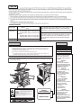
SERVICE MANUAL
CODE: 00ZARM455UA1E
DIGITAL MULTIFUNCTIONAL
SYSTEM
MODEL
AR-M351U/M451U
AR-M355U/M455U
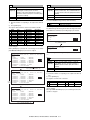
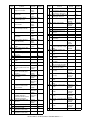
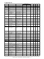
CONTENTS
[1] GENERAL. . . . . . . . . . . . . . . . . . . . . . . . . . . . . . . . . . . . . . . . . . . . 1-1
[2] CONFIGURATION . . . . . . . . . . . . . . . . . . . . . . . . . . . . . . . . . . . . . 2-1
[3] SPECIFICATIONS . . . . . . . . . . . . . . . . . . . . . . . . . . . . . . . . . . . . . 3-1
[4] CONSUMABLE PARTS . . . . . . . . . . . . . . . . . . . . . . . . . . . . . . . . . 4-1
[5] EXTERNAL VIEWS AND INTERNAL STRUCTURES . . . . . . . . . . 5-1
[6] UNPACKING AND INSTALLATION . . . . . . . . . . . . . . . . . . . . . . . . 6-1
[7] MAINTENANCE AND DETAILS OF EACH SECTION . . . . . . . . . . 7-1
[8] ADJUSTMENTS . . . . . . . . . . . . . . . . . . . . . . . . . . . . . . . . . . . . . . . 8-1
[9] SIMULATIONS . . . . . . . . . . . . . . . . . . . . . . . . . . . . . . . . . . . . . . . . 9-1
[10] MACHINE OPERATION . . . . . . . . . . . . . . . . . . . . . . . . . . . . . . . . 10-1
[11] TROUBLE CODES . . . . . . . . . . . . . . . . . . . . . . . . . . . . . . . . . . . . 11-1
[12] ROM VERSION-UP METHOD . . . . . . . . . . . . . . . . . . . . . . . . . . . 12-1
[13] ELECTRICAL SECTION. . . . . . . . . . . . . . . . . . . . . . . . . . . . . . . . 13-1
Parts marked with “ ” are important for maintaining the safety of the set. Be sure to replace these parts with
specified ones for maintaining the safety and performance of the set.
SHARP CORPORATION
This document has been published to be used
for after sales service only.
The contents are subject to change without notice.
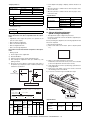
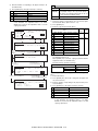
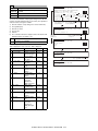
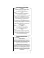
CAUTION
Cautions on laser
785 nm
Wave length
+10 nm
−15 nm
North America:
35 cpm model: (6.2 µs ± 6.2 ns)/7 mm
45 cpm model: (4.8 µs ± 4.8 ns)/7 mm
Europe:
35 cpm model: (6.2 µs ± 6.2 ns)/7 mm
45 cpm model: (4.8 µs ± 4.8 ns)/7 mm
Pulse times
Output power
0.2 mW - 0.4 mW
At the production line, the output power of the scanner unit
is adjusted to 0.4 MILLIWATT PLUS 8 % and is maintained
constant by the operation of the Automatic Power Control (APC).
Caution
This product contains a low power laser device. To ensure
safety do not remove any cover or attempt to gain access
to the inside of the product. Refer all servicing to qualified
personnel.
For North America:
For Europe:
CLASS 1 LASER PRODUCT
SAFETY PRECAUTIONS
This Digital Equipment is rated Class 1 and complies with 21 CFR 1040.10 and 1040.11 of the
CDRH standards. This means that the equipment does not produce hazardous laser radiation. For
your safety, observe the precautions below.
LASER KLASSE 1
LUOKAN 1 LASERLAITE
KLASS 1 LASERAPPARAT
●
Do not remove the cabinet, operation panel or any other covers.
●
The equipment's exterior covers contain several safety interlock switches. Do not bypass any
safety interlock by inserting wedges or other items into switch slots.
Caution
Use of controls or adjustments or performance of procedures other than those specified herein may result in
hazardous radiation exposure.
CAUTION
INVISIBLE LASER RADIATION
WHEN OPEN INTERLOCKS
DEFEATED. AVOID EXPOSURE
TO BEAM.
VORSICHT
UNSICHTBARE
LASERSTRAHLUNG WENN
ABDECKUNG GEÖFFNET UND
SICHERHEITSVERRIEGELUNG
ÜBERBRÜCKT. NICHT DEM
STRAHL AUSSETZEN.
ADVARSEL
USYNLIG LASERSTRÅLNING
VED ÅBNING, NÅR
SIKKERHEDSBRYDERE ER
UDE AF FUNKTION. UNDGÅ
UDSAETTELSE FOR
STRÅLNING.
VAROITUS!
LAITTEEN KÄYTTÄMINEN
MUULLA KUIN TÄSSÄ
KÄYTTÖOHJEESSA
MAINITULLA TAVALLA SAATTAA
ALTISTAA KÄYTTÄJÄN
TURVALLISUUSLUOKAN 1
YLITTÄVÄLLE
NÄKYMÄTTÖMÄLLE
LASERSÄTEILYLLE.
CAUTION
VORSICHT
ADVARSEL
ADVERSEL
VARNING
VARO!
INVISIBLE LASER RADIATION WHEN OPEN AND INTERLOCKS DEFEATED.
AVOID EXPOSURE TO BEAM.
Laserstrahl
UNSICHTBARE LASERSTRAHLUNG WENN ABDECKUNG GEÖFFNET UND
SICHERHEITSVERRIEGELUNG ÜBERERÜCKT. NICHT DEM STRAHL AUSSETZEN.
USYNLIG LASERSTRÅLING VED ÅBNING, NÅR SIKKERHEDSAFBRYDERE ER
UDE AF FUNKTION. UNDGÅ UDSAETTELSE FOR STRÅLNING.
CLASS 1
LASER PRODUCT
USYNLIG LASERSTRÅLING NÅR DEKSEL ÅPNES OG SIKKERHEDSLÅS BRYTES.
UNNGÅ EKSPONERING FOR STRÅLEN.
OSYNLIG LASERSTRÅLNING NÄR DENNA DEL ÄR ÖPPNAD OCH SPÄRRAR ÄR
URKOPPLADE. STRÅLEN ÄR FARLIG. BETRAKTA EJ STRÅLEN.
AVATTAESSA JA SUOJALUKITUS OHITETTAESSA OLET ALTTIINA NÄKYMÄTÖNTÄ
LASERSÄTEILYLLE. ÄLÄ KATSO SÄTEESEEN.
LASER KLASSE 1
VARNING
OM APPARATEN ANVÄNDS PÅ
ANNAT SÄTT ÄN I DENNA
BRUKSANVISNING
SPECIFICERATS, KAN
ANVÄNDAREN UTSÄTTAS FÖR
OSYNLIG LASERSTRÅLNING,
SOM ÖVERSKRIDER GRÄNSEN
FÖR LASERKLASS 1.
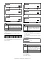
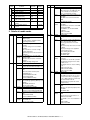
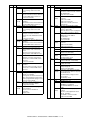
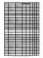
CONTENTS
[1]
GENERAL
[2]
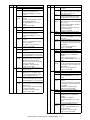
[5]
EXTERNAL VIEWS AND INTERNAL STRUCTURES
Note for servicing . . . . . . . . . . . . . . . . . . . . . . . . . . . .1-1
1.
A. Cautions for servicing . . . . . . . . . . . . . . . . . . . . . .1-1
2.
Interior . . . . . . . . . . . . . . . . . . . . . . . . . . . . . . . . . . . . 5-2
CONFIGURATION
3.
Operation panel. . . . . . . . . . . . . . . . . . . . . . . . . . . . . 5-3
1.
4.
Job status screen (common to print, copy, fax,
network scan and Internet fax) . . . . . . . . . . . . . . . . . 5-4
5.
Cross sectional view . . . . . . . . . . . . . . . . . . . . . . . . . 5-5
1.
System configuration . . . . . . . . . . . . . . . . . . . . . . . . .2-1
A. Basic system . . . . . . . . . . . . . . . . . . . . . . . . . . . . .2-1
B. Option lineup . . . . . . . . . . . . . . . . . . . . . . . . . . . . .2-2
Exterior . . . . . . . . . . . . . . . . . . . . . . . . . . . . . . . . . . . 5-1
A. Scanner unit . . . . . . . . . . . . . . . . . . . . . . . . . . . . . 5-5
C. List of combination of peripheral devices . . . . . . .2-4
B. Engine . . . . . . . . . . . . . . . . . . . . . . . . . . . . . . . . . 5-5
[3]
SPECIFICATIONS
1.
6.
Basic Specification . . . . . . . . . . . . . . . . . . . . . . . . . . .3-1
A. Scanner unit . . . . . . . . . . . . . . . . . . . . . . . . . . . . . 5-6
A. Base Engine . . . . . . . . . . . . . . . . . . . . . . . . . . . . .3-1
B. Engine . . . . . . . . . . . . . . . . . . . . . . . . . . . . . . . . . 5-6
B. Document Feeding Equipment . . . . . . . . . . . . . . .3-2
7.
C. Output Equipment . . . . . . . . . . . . . . . . . . . . . . . . .3-2
2.
B. Engine . . . . . . . . . . . . . . . . . . . . . . . . . . . . . . . . . 5-7
A. Printer Function . . . . . . . . . . . . . . . . . . . . . . . . . . .3-2
8.
B. Image send function . . . . . . . . . . . . . . . . . . . . . . .3-5
[4]
4.
Rack for Scanner . . . . . . . . . . . . . . . . . . . . . . . . . . . .3-9
CONSUMABLE PARTS
1.
Supply system table . . . . . . . . . . . . . . . . . . . . . . . . . .4-1
B. Engine . . . . . . . . . . . . . . . . . . . . . . . . . . . . . . . . . 5-8
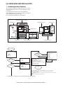
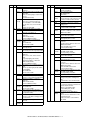
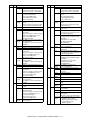
[6]
UNPACKING AND INSTALLATION
1.
Installing procedure flowchart . . . . . . . . . . . . . . . . . . 6-1
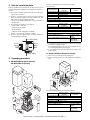
2.
Note for installation place . . . . . . . . . . . . . . . . . . . . . 6-2
3.
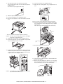
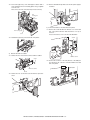
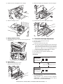
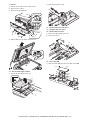
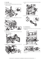
Unpacking procedure . . . . . . . . . . . . . . . . . . . . . . . . 6-2
A. European Subsidiary/East Europe/Russia/
Australia/New Zealand . . . . . . . . . . . . . . . . . . . . .4-1
A. AR-M355U/M455U (North America),
AR-M351U/M451U (Europe) . . . . . . . . . . . . . . . . 6-2
B. Taiwan (Aurora). . . . . . . . . . . . . . . . . . . . . . . . . . .4-1
C. Asia . . . . . . . . . . . . . . . . . . . . . . . . . . . . . . . . . . . .4-1
B. AR-M351U/M451U (Except for Europe) . . . . . . . 6-2
4.
Remove the locking tape
(AR-M355U/M455U (North America),
AR-M351U/M451U (Europe)) . . . . . . . . . . . . . . . . . . 6-3
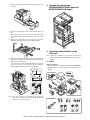
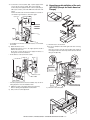
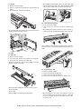
5.
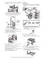
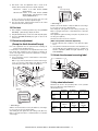
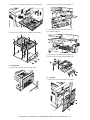
Unpacking and installation of the desk unit . . . . . . . . 6-3
D. Middle East/Africa/Israel/Philippines . . . . . . . . . . .4-1
E. Hong Kong . . . . . . . . . . . . . . . . . . . . . . . . . . . . . .4-1
F. China . . . . . . . . . . . . . . . . . . . . . . . . . . . . . . . . . . .4-1
2.
Maintenance parts list. . . . . . . . . . . . . . . . . . . . . . . . .4-2
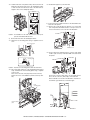
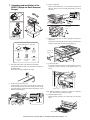
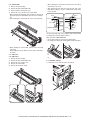
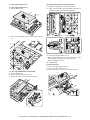
A. AR-D28 . . . . . . . . . . . . . . . . . . . . . . . . . . . . . . . . 6-3
A. Europe/Australia/New Zealand/Taiwan . . . . . . . . .4-2
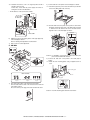
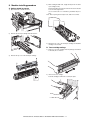
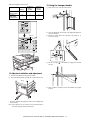
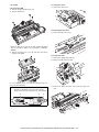
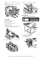
B. AR-D27 . . . . . . . . . . . . . . . . . . . . . . . . . . . . . . . . 6-5
B. Agency/Asia/Middle East/Africa/
Latin America . . . . . . . . . . . . . . . . . . . . . . . . . . . .4-2
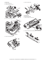
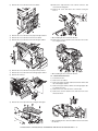
C. AR-MU2 . . . . . . . . . . . . . . . . . . . . . . . . . . . . . . . . 6-7
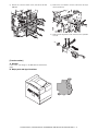
6.
Unpacking and installation of the rack (AR-RK2)
(Except for North America/Europe) . . . . . . . . . . . . . . 6-9
7.
Unpacking and installation of the AR-EF3
(Except for North America/Europe) . . . . . . . . . . . . . 6-10
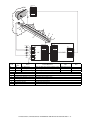
8.
Machine installing procedure. . . . . . . . . . . . . . . . . . 6-11
C. Hong Kong . . . . . . . . . . . . . . . . . . . . . . . . . . . . . .4-3
D. China . . . . . . . . . . . . . . . . . . . . . . . . . . . . . . . . . . .4-3
2.
Production number identification . . . . . . . . . . . . . . . .4-4
A. Drum cartridge. . . . . . . . . . . . . . . . . . . . . . . . . . . .4-4
A. Setting related to process . . . . . . . . . . . . . . . . . 6-11
B. Toner cartridge . . . . . . . . . . . . . . . . . . . . . . . . . . .4-4
B. Toner cartridge settings . . . . . . . . . . . . . . . . . . . 6-11
C. Developer cartridge . . . . . . . . . . . . . . . . . . . . . . . .4-4
3.
Motor, Clutch, Solenoid . . . . . . . . . . . . . . . . . . . . . . . 5-8
A. Scanner unit . . . . . . . . . . . . . . . . . . . . . . . . . . . . . 5-8
C. Copy function . . . . . . . . . . . . . . . . . . . . . . . . . . . .3-7
B/W Scanner Module (DSPF). . . . . . . . . . . . . . . . . . .3-8
PWB . . . . . . . . . . . . . . . . . . . . . . . . . . . . . . . . . . . . . 5-7
A. Scanner unit . . . . . . . . . . . . . . . . . . . . . . . . . . . . . 5-7
Specific Function . . . . . . . . . . . . . . . . . . . . . . . . . . . .3-2
3.
Switch, Sensor . . . . . . . . . . . . . . . . . . . . . . . . . . . . . 5-6
C. Setting related to fusing . . . . . . . . . . . . . . . . . . . 6-12
Environmental conditions . . . . . . . . . . . . . . . . . . . . . .4-4
D. Paper setting . . . . . . . . . . . . . . . . . . . . . . . . . . . 6-12
A. Operating conditions . . . . . . . . . . . . . . . . . . . . . . .4-4
B. Storage conditions. . . . . . . . . . . . . . . . . . . . . . . . .4-4
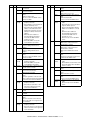
9.
Automatic developer adjustment . . . . . . . . . . . . . . . 6-12
10. Print test . . . . . . . . . . . . . . . . . . . . . . . . . . . . . . . . . 6-13
11. Distortion adjustment
(Except for North America/Europe) . . . . . . . . . . . . . 6-13
12. Attach the document scanning label . . . . . . . . . . . . 6-13
13. Key sheet attachment . . . . . . . . . . . . . . . . . . . . . . . 6-13
14. Adjuster installation and adjustment . . . . . . . . . . . . 6-14
15. Using the transport handle . . . . . . . . . . . . . . . . . . . 6-14
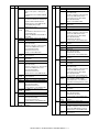
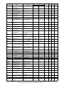
[7]
MAINTENANCE AND DETAILS OF EACH SECTION
[9]
SIMULATION
[Maintenance System Table] . . . . . . . . . . . . . . . . . . . . . . .7-1
1.
Outline and purpose . . . . . . . . . . . . . . . . . . . . . . . . . 9-1
1.
Engine section . . . . . . . . . . . . . . . . . . . . . . . . . . . . . .7-1
2.
Code-type simulation. . . . . . . . . . . . . . . . . . . . . . . . . 9-1
2.
Scanner / DSPF . . . . . . . . . . . . . . . . . . . . . . . . . . . . .7-2
A. Operating procedures and operations . . . . . . . . . 9-1
3.
Peripheral devices . . . . . . . . . . . . . . . . . . . . . . . . . . .7-3
B. Simulation list . . . . . . . . . . . . . . . . . . . . . . . . . . . . 9-3
C. Details . . . . . . . . . . . . . . . . . . . . . . . . . . . . . . . . . 9-7
[DETAILS OF EACH SECTION] . . . . . . . . . . . . . . . . . . . .7-4
1.
Process section . . . . . . . . . . . . . . . . . . . . . . . . . . . . .7-4
[OPC drum section] . . . . . . . . . . . . . . . . . . . . . . . . . .7-6
[Transfer section] . . . . . . . . . . . . . . . . . . . . . . . . . . .7-11
3.
[10] MACHINE OPERATION
1.
Acceptable originals . . . . . . . . . . . . . . . . . . . . . . . . 10-1
[Developing section] . . . . . . . . . . . . . . . . . . . . . . . . .7-16
A. Size and weight of acceptable originals . . . . . . . 10-1
2.
Fusing section. . . . . . . . . . . . . . . . . . . . . . . . . . . . . .7-21
3.
Paper feed section . . . . . . . . . . . . . . . . . . . . . . . . . .7-26
B. Total number of originals that can be set
in the document feeder tray . . . . . . . . . . . . . . . . 10-1
4.
Transport section/Paper exit reverse section . . . . . .7-33
2.
Standard original placement orientations . . . . . . . . 10-1
5.
Laser scanner section. . . . . . . . . . . . . . . . . . . . . . . .7-43
3.
6.
Scanner section . . . . . . . . . . . . . . . . . . . . . . . . . . . .7-46
Automatic copy image rotation rotation copying . . . . . . . . . . . . . . . . . . . . . . . . . . . . 10-1
7.
DSPF section . . . . . . . . . . . . . . . . . . . . . . . . . . . . . .7-54
4.
Specifications of paper trays . . . . . . . . . . . . . . . . . . 10-2
8.
Operation panel section . . . . . . . . . . . . . . . . . . . . . .7-62
9.
Filter . . . . . . . . . . . . . . . . . . . . . . . . . . . . . . . . . . . . .7-66
10. Drive section . . . . . . . . . . . . . . . . . . . . . . . . . . . . . . .7-67
A. Applicable plain paper . . . . . . . . . . . . . . . . . . . . 10-2
B. Applicable special paper . . . . . . . . . . . . . . . . . . 10-3
5.
12. PWB . . . . . . . . . . . . . . . . . . . . . . . . . . . . . . . . . . . . .7-72
13. Fan motor . . . . . . . . . . . . . . . . . . . . . . . . . . . . . . . . .7-74
ADJUSTMENTS
1.
Process section . . . . . . . . . . . . . . . . . . . . . . . . . . . . .8-1
A. Doctor gap adjustment . . . . . . . . . . . . . . . . . . . . .8-1
B. MG roller main pole position adjustment . . . . . . . .8-1
C. High voltage output adjustment. . . . . . . . . . . . . . .8-2
2.
Image check, adjustment . . . . . . . . . . . . . . . . . . . . . .8-3
A. Adjustments on the engine side . . . . . . . . . . . . . .8-3
[11] TROUBLE CODES
1.
General . . . . . . . . . . . . . . . . . . . . . . . . . . . . . . . . . . 11-1
2.
Trouble codes list . . . . . . . . . . . . . . . . . . . . . . . . . . 11-1
3.
Details of trouble codes . . . . . . . . . . . . . . . . . . . . . . 11-3
4.
Other related items . . . . . . . . . . . . . . . . . . . . . . . . 11-14
[12] ROM VERSION-UP METHOD
1.
General . . . . . . . . . . . . . . . . . . . . . . . . . . . . . . . . . . 12-1
2.
Cautions . . . . . . . . . . . . . . . . . . . . . . . . . . . . . . . . . 12-1
3.
Flash ROM update procedures . . . . . . . . . . . . . . . . 12-1
A. Preliminary arrangement . . . . . . . . . . . . . . . . . . 12-1
B. Adjustment on the scanner side . . . . . . . . . . . . . .8-6
3.
B. Update procedure 1 (Writing with each ROM
inserted to the specified slot) . . . . . . . . . . . . . . . 12-2
Scanner section . . . . . . . . . . . . . . . . . . . . . . . . . . . .8-10
A. OC scan distortion adjustment
(MB-B rail height adjustment) . . . . . . . . . . . . . . .8-10
C. Update procedures 2 (Writing to each ROM
by use of CN6 of the controller PWB) . . . . . . . . 12-2
B. Vertical image distortion balance
adjustment (Copy lamp unit installing
position adjustment) . . . . . . . . . . . . . . . . . . . . . .8-11
D. In case of “Result: NG” . . . . . . . . . . . . . . . . . . . 12-3
E. Turning off the power during update . . . . . . . . . 12-3
F. Update window display in normal booting . . . . . 12-3
C. Vertical image distortion balance adjustment
(No. 2/3 mirror base unit installing and
position adjustment) . . . . . . . . . . . . . . . . . . . . . .8-11
D. Vertical (sub scanning direction) distortion
adjustment [Winding pulley position
adjustment] . . . . . . . . . . . . . . . . . . . . . . . . . . . . .8-11
E. Height adjustment of original detection light
emitting unit . . . . . . . . . . . . . . . . . . . . . . . . . . . . .8-12
F. Original size detection photo sensor check . . . . .8-12
G. Original size detection photo sensor
adjustment. . . . . . . . . . . . . . . . . . . . . . . . . . . . . .8-12
H. Image density adjustment . . . . . . . . . . . . . . . . . .8-13
I. DSPF width detection adjustment . . . . . . . . . . . .8-17
Printing onto envelopes . . . . . . . . . . . . . . . . . . . . . . 10-3
A. Fusing unit pressure adjusting levers . . . . . . . . 10-3
11. Power section . . . . . . . . . . . . . . . . . . . . . . . . . . . . . .7-69
[8]
Other related items . . . . . . . . . . . . . . . . . . . . . . . . . 9-87
G. Update process flow . . . . . . . . . . . . . . . . . . . . . 12-3
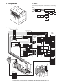
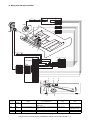
[13] ELECTRICAL SECTION
1.
Block diagram . . . . . . . . . . . . . . . . . . . . . . . . . . . . . 13-1
2.
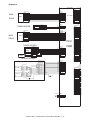
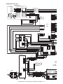
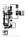
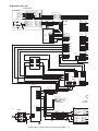
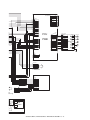
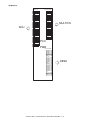
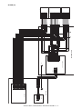
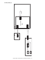
Actual wiring chart . . . . . . . . . . . . . . . . . . . . . . . . . . 13-2
3.
Signal name list . . . . . . . . . . . . . . . . . . . . . . . . . . . 13-19
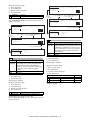
[1] GENERAL
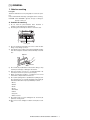
1. Note for servicing
Pictogram
This Service Manual uses some pictographs to assure safe operation.
Please understand the meanings of pictographs before servicing.
CAUTION: If this CAUTION is ignored, an injury or damage to
property could occur.
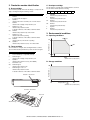
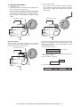
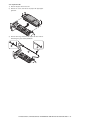
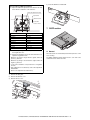
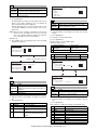
A. Cautions for servicing
1) Do not touch the photoconductive drum. Scratches or
smudges on the drum will cause dirty printouts.
2) The fusing unit is extremely hot. Exercise care in this area.
Fusing unit
3) Do not look directly at the light source of the scanner module.
Doing so may damage your eyes.
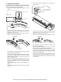
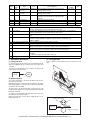
4) Five adjusters are provided on all optional stand/paper drawer
units. These adjusters should be lowered until they contact the
floor.
Adjuster
Lock
Release
5) Do not make any modifications to this machine. Doing so may
result in personal injury or damage to the machine.
6) Since this machine is heavy, it is recommended that it be
moved by more than one person to prevent injury.
7) When connecting this machine to a computer, be sure to first
turn both the computer and the machine off.
8) Do not print anything which is prohibited from printing by law.
The following items are normally prohibited from printing by
national law. Other items may be prohibited by local law.
• Money
• Stamps
• Bonds
• Stocks
• Bank drafts
• Checks
• Passports
• Driver's licenses
9) Do not throw toner or a toner cartridge into fire. Toner may be
spattered, causing a burn.
10) Store toner or toner cartridges in a hard-to-reach place for children.
AR-M351U/M451U, AR-M355U/M455U GENERAL 1 - 1
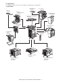
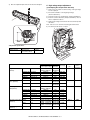
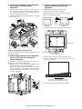
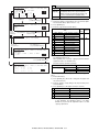
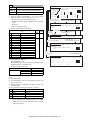
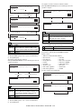
[2] CONFIGURATION
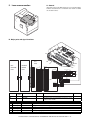
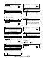
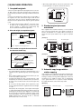
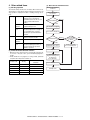
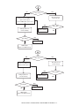
1. System configuration
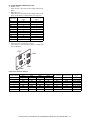
A. Basic system
AR-M351U/M451U
(Copier/Printer model)
AR-M355U/M455U
(Copier model)
Necessary options
• Any one of the stand/MPD & 2000 sheet paper drawer (AR-D28), the stand/3 x 500 sheet paper drawer (AR-D27), or the multi purpose
drawer (AR-MU2)*
• Any one of the upper exit tray extension (AR-TE4), the finisher (AR-FN6), the mail-bin stacker (AR-MS1), or the right upper exit tray
(AR-TE5)
• AR-EF3
• AR-RK2
* To install the AR-MU2, the exclusive-use desk is required.
AR-M351U/M451U, AR-M355U/M455U CONFIGURATION 2 - 1
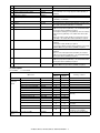
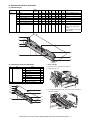
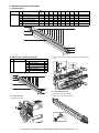
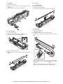
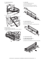
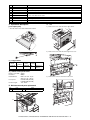
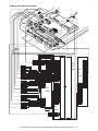
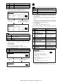
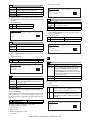
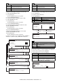
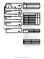
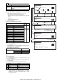
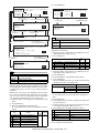
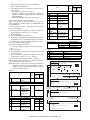
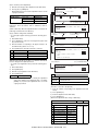
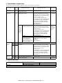
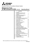
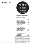
B. Option lineup
For combinations of options, refer to "C. List of combination of peripheral devices" described later.
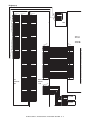
(1) Major options
5. Upper exit tray
(AR-TE4)
7. Exit tray
(AR-TE3)
11. Finisher
(AR-FN6)
8. Duplex
module/bypass tray
(AR-DU4)
6. Right upper exit
tray (AR-TE5)
1. Scanner module with DSPF
(AR-EF3)
9. Duplex module
(AR-DU3)
12. Mail-bin stacker
(AR-MS1)
10. Saddle stitch
finisher
(AR-FN7)
13. Fax expansion kit
(AR-FX12)
4. Multi purpose drawer
(AR-MU2)
2. Stand/MPD & 2000 sheet
paper drawer
(AR-D28)
3. Stand/3 x 500 sheet
paper drawer
(AR-D27)
AR-M351U/M451U, AR-M355U/M455U CONFIGURATION 2 - 2
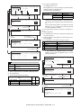
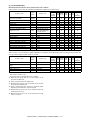
No.
Option item
Installing conditions
1
Scanner module with DSPF
AR-EF3
2
Stand/MPD & 2000 sheet paper drawer
AR-D28
3
Stand/3 x 500 sheet paper drawer
AR-D27
4
Multi purpose drawer
AR-MU2
5
Upper exit tray
AR-TE4
6
Right upper exit tray
AR-TE5
7
Exit tray
AR-TE3
• Required when the duplex module (AR-DU3) is installed and
the saddle stitch finisher (AR-FN7) is not installed.
• Any one of the multi purpose drawer (AR-MU2), the stand/3 x
500 sheet paper drawer (AR-D27), or the stand/MPD & 2000
sheet paper drawer (AR-D28) is required.
• The duplex module/bypass tray (AR-DU4) cannot be installed
with the exit tray (AR-TE3) or the saddle stitch finisher (ARFN7).
• When the duplex module (AR-DU3) is installed, the exit tray
(AR-TE3) or the saddle stitch finisher (AR-FN7) is required.
• Simultaneous installation with the large capacity paper feed
desk (AR-D28) or the 3-stage paper feed desk (AR-D27) is
inhibited.
• Required when the finisher (AR-FN6) or the mail-bin stacker
(AR-MS1) is not installed.
8
Duplex module/bypass tray
AR-DU4
9
Duplex module
AR-DU3
10
Saddle stitch finisher
AR-FN7
• Simultaneous installation with the finisher (AR-FN6) is
inhibited.
• The duplex module (AR-DU3) is required.
• The stand/3 x 500 sheet paper drawer (AR-D27) or the stand/
MPD & 2000 sheet paper drawer (AR-D28) is required.
11
Finisher
AR-FN6
• Simultaneous installation with the saddle finisher (AR-FN7) is
inhibited.
• Any one of the multi paper drawer (AR-MU2), the stand/3 x
500 sheet paper drawer (AR-D27), or the stand/MPD & 2000
sheet paper drawer (AR-D28) is required.
12
Mail-bin stacker
AR-MS1
• Any one of the multi paper drawer (AR-MU2), the stand/3 x
500 sheet paper drawer (AR-D27), or the stand/MPD & 2000
sheet paper drawer (AR-D28) is required.
13
Fax expansion kit
AR-FX12
• The stand/3 x 500 sheet paper drawer (AR-D27), or the stand/
MPD & 2000 sheet paper drawer (AR-D28) is required.
(2) Other options
❍: Installable
✕: Not available
Main unit
Option item
AR-M351U/
M451U
AR-M355U/
M455U
Installing conditions
For saddle stitch finisher (AR-FN7)
Paper exit unit
Punch unit
AR-PN1
❍
❍
Function
expansion
options
Printer expansion kit
AR-P20
✕
❍
Printer expansion kit (with HDD)
AR-P21
✕
❍
Printer server card
AR-NC7
❍
✕
Printer server card (with HDD)
AR-NC8
❍
✕
PS3 expansion kit
AR-PK6
❍
❍
Network scanner expansion kit
AR-NS3
❍
❍
Sharpdesk 1 license kit
AR-U11M
❍
❍
Sharpdesk 5 license kit
AR-U15M
❍
❍
Sharpdesk 50 license kit
AR-U1AM
❍
❍
Sharpdesk 100 license kit
AR-U1BM
❍
❍
Data security kit
AR-FR22/FR22U
❍
❍
Data security kit
AR-FR21/FR21U
❍
❍
Bar code font
AR-PF1
❍
❍
Flash ROM kit
AR-PF2
❍
❍
Cannot be installed together with
the AR-P21 or the AR-NC8.
Fax memory (8 MB)
AR-MM9
❍
❍
For fax expansion kit (AR-FX12)
FAX-related
option
AR-M351U/M451U, AR-M355U/M455U CONFIGURATION 2 - 3
For network scanner expansion kit
(AR-NS3)
When the AR-P21 or the AR-NC8
is installed.
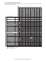
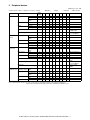
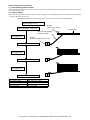
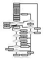
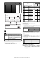
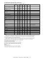
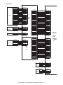
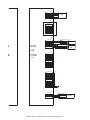
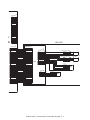
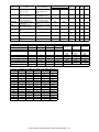
C. List of combination of peripheral devices
As shown in the table below, some other peripheral devices (B) may be needed for installation of a peripheral device (A) and some peripheral devices cannot be installed together.
Multi purpose drawer
AR-MU2
Stand/3 x 500 sheet
paper drawer
AR-D27
Stand/MPD & 2000 sheet
paper drawer
AR-D28
Duplex module/bypass tray
AR-DU4
*1
Duplex module
AR-DU3
*1
Scanner module with DSPF
AR-EF3
Output units
Saddle stitch finisher
A
*1
AR-FN7
AR-FN6
*1
Mail-bin stacker
AR-MS1
*1
Exit tray
AR-TE3
Upper exit tray
AR-TE4
Right upper exit tray
AR-TE5
Punch unit
AR-PN1
*1
*1
AR-P20
Printer expansion kit (with HDD) AR-P21
Print server card
AR-NC7
Print server card (with HDD)
AR-NC8
PS3 expansion kit
AR-PK6
*1
1
Network scanner expansion kit
AR-NS3
*
Facsimile expansion kit
AR-FX12
*1
Fax memory (8 MB)
AR-MM9
*1
Bar code font
AR-PF1
Flash ROM kit
AR-PF2
Data security kit
Data security kit
AR-FR22
AR-FR22U
Data security kit
AR-FR21
Data security kit
AR-FR21U
*1
= Must be installed together.
*1 = Any of the units must be installed together.
= Cannot be installed together.
AR-M351U/M451U, AR-M355U/M455U CONFIGURATION 2 - 4
Data security kit (AR-FR21U)
Data security kit (AR-FR21)
Data security kit (AR-FR22U)
Flash ROM kit
Data security kit (AR-FR22)
Bar code font
Fax memory (8 MB)
Network scanner expansion kit
Facsimile expansion kit
Print server card (with HDD)
PS3 expansion kit
Print server card
Printer expansion kit (with HDD)
Punch unit
Printer expansion kit
Right upper exit tray
Upper exit tray
Exit tray
Mail-bin stacker
Finisher
Saddle stitch finisher
Duplex module
Scanner module with DSPF
Duplex module/bypass tray
*1
Finisher
Related to extension of
functions and others
Printer expansion kit
Stand/MPD & 2000 sheet
Related to paper feed unit
Stand/3 x 500 sheet paper drawer
Multi purpose drawer
B
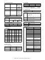
[3] SPECIFICATIONS
(in mm)
1. Basic Specification
A. Base Engine
(1) Form
Console type
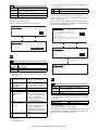
(2) Engine speed
AR-M351U/
AR-M451U/
M355U
M455U
A4, 8.5" x 11"
35ppm (31ppm*) 45ppm (40ppm*)
A4R, 8.5" x 11"R
25ppm
30ppm
A5R/5.5" x 8.5"R, Invoice-R
35ppm
45ppm
B5
35ppm
45ppm
B5R, Executive-R
25ppm
30ppm
B4/8.5" x 14"
20ppm
22ppm
A3/11" x 17"
17ppm
20ppm
8K
17ppm
20ppm
16K
35ppm
45ppm
Paper size
* Paper feed from Manual bypass tray
(3) Engine composition
Photoconductor type
Record method
Development method
Charge method
Transfer method
Cleaning method
Fusing method
OPC
(diameter of photoconductor : ø30mm)
Electro-photograph (laser)
Dry-type dual-component magnetic
brush development
Charged saw-tooth method
Transfer roller
Counter blade
Heat roller
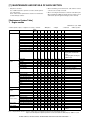
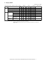
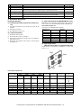
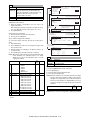
(4) Engine resolution
Resolution
A
297
257
210
182
148
100
279
216
216
216
184
140
105
162
98
110
176
B
420
364
297
257
210
148
432
356
330
279
267
216
241
229
191
220
250
C
4
4
4
4
4
4
4
4
4
4
4
4
4
4
4
4
4
D
289
242
202
168
140
92
271
208
208
208
183
132
97
154
90
102
168
E
4
4
4
4
4
4
4
4
4
4
4
4
4
4
4
4
4
(6) Warm-up
Warm-up time
Pre-heat requirement
Jam recovery time
less than 80 seconds
Required
Target: about 30 seconds
(Under standard condition of 60
seconds left after side cover opening,
polygon motor halt)
(7) Power source
Voltage
100V system
100-127V
50/60Hz
Inlet type
Frequency
Power cord
200V system
220-240V
(8) Power consumption
Read: 600dpi
Write: 600dpi
Write: 1200dpi equivalent
Write: 2 levels
Smoothing
Gradation
Paper size
A3
B4
A4
B5
A5
Japanese postcard
Ledger
Legal
Foolscap
Letter
Executive
Invoice
Com-10 (envelope)
C5 (envelope)
Monarch (envelope)
DL (envelope)
ISO B5 (envelope)
Max. Power
consumption
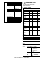
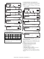
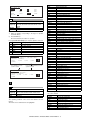
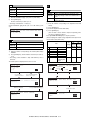
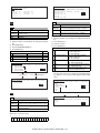
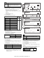
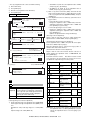
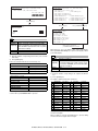
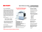
(5) Printable area
The print area of this product is shown below.
Except for Taiwan
Taiwan
200V
AR-M451U/
M455U
1440W
1550W
1850W
(9) Energy Star benchmark
E
C
AR-M351U/
M355U
1440W
1550W
1850W
Low power mode
Recovery time from
low power mode
Sleep mode
Transition time to
sleep mode
C
AR-M351U/M355U
184.75W
Max. 30 sec.
Less than 80W
60 min.
AR-M451U/M455U
223.25W
Max. 30 sec.
(Recommendation)
Less than 95W
60 min.
(10) Noise
B
At working
At waiting mode
less than 6.8dB
less than 5.0dB
∗ Showing noise benchmark in each model as a whole system.
(11) Dimensions
External dimensions
(W x D x H)
E
D
A
Paper size
Printable area
Occupied space
dimensions
(W x D)
Weight
37.9" x 26.2" x 44.4"
(963 mm x 665 mm x 1127 mm)
(including automatic document feeder)
37.9" x 26.2" (963 x 665 mm)
(Include automatic document feeder)
Engine: Approx. 85.8 lb (38.9 kg)
Desk: Approx. 72.6 lb (32.9 kg)
Rack: Approx. 16 lb (7.4 kg)
DSPF: Approx. 46 lb (21 kg)
If a printer driver for Windows or Macintosh is used for printing, the
printable area will be smaller. The actual printable area depends
on the printer driver to be used.
AR-M351U/M451U, AR-M355U/M455U SPECIFICATIONS 3 - 1
B. Document Feeding Equipment
(2) Support OS
(1) One-drawer tray (included in the base engine)
Custom PS
Paper feed method
Sizes to be fed
Paper capacity
Media available for
paper feeding
Paper type
Custom
PCL5e/6(XL)
Paper size switching
Dehumidification
heater
Balance detection
Default size setting
Mounting/demounting
of the tray
One-drawer tray
A4, B5, 8.5" x 11"
500 sheets (at 80g/m²)
Plain paper 60 - 105g/m², 16 - 28lbs
Plain, recycled, pre-printed, prepunched, color, letter head
To be switched by user
(paper size to be entered from the
operation panel).
Not provided
Provided (paper empty and 3 steps)
100V system
8.5" x 11"
Provided
C. Output Equipment
(1) Face-down Exit Tray (included in the base engine)
Output position/
method
Output paper capacity
Output paper size
Spec of media for
paper output
PPD
Face-down output at the upper side of
main unit
400 sheets (80g/m² sheet)
A3, B4, A4, A4R, B5, B5R, A5R
11 " x 17", 8.5" x 14", 8.5" x 13",
8.5" x 11", 8.5" x 11"R, 5.5" x 8.5"R
Executive, Japanese post card,
Monarch (98 x 191), 8K, 16K, 16KR
Com-10 (105 x 241), DL (110 x 220),
C5 (162 x 229), ISO B5 (176 x 250)
Tracing paper: 52 ~ 59g/m² / 14 ~ 15lbs
Plain paper: 60 ~ 128g/m² / 16 ~ 34lbs
Index paper: 176g/m² / 47lbs
Cover paper: 205g/m² / 54 ~ 55lbs
Transparency firm
Not provided
Remaining paper
detection
Exit tray full detection Provided
2. Specific Function
A. Printer Function
To enable the printer function of the AR-M355U/M455U, the
printer expansion kit must be installed.
(1) Platform
IBM PC/AT (Include compatible machine)
Macintosh
Windows 95/98/Me
Windows NT 4.0 (Service Pack5 or later)
Windows Server 2003
Windows 2000 Server
Windows 2000
Windows XP
Windows 95/98/Me
Windows NT 4.0 (Service Pack5 or later)
Windows Server 2003
Windows 2000 Server
Windows 2000
Windows XP
Windows 95/98/Me
Windows NT 4.0 (Service Pack5 or later)
Windows Server 2003
Windows 2000 Server
Windows 2000
Windows XP
MacOS 8.6 - 9.2.2, 10.1.5, 10.2 - 10.2.8
(except for Mac OS 10.2.2), 10.3-10.3.3
(3) PDL emulation
PCL6 compatible, PCL5e compatible, PostScript 3 compatible
(4) Windows driver function
a. General
Function
PCL5e
PCL6
Copies
Orientation
1-999
Portrait
Landscape
Duplex
1-sided
2-sided
(Left /top/ right
binding)
Booklet
Invoice on Letter
Letter on Ledger
A5 on A4
A4 on A3
B5 on B4
Letter on Letter
Ledger on Ledger
A4 on A4
A3 on A3
B4 on B4
Binding edge Left / top / right
N-up
2/4/6/8/9/16
N-up order
N-up border
Z / Reversed Z /
N / Reversed N
Yes / No
PS
PPD file *1
(for Windows XP)
Portrait
Landscape-A
Landscape-B
(*2)
1-sided
2-sided
(Long / short
binding)
(*2)
Yes
(2up booklet only)
(*2)
–
2 / 4 / 6 / 9 / 16
(*2)
Z (*2)
Always Yes (*2)
*1: For printing, PS driver bundled with the Windows is required.
*2: Since the function is of PS driver bundled with Windows, specification may vary according to the OS.
AR-M351U/M451U, AR-M355U/M455U SPECIFICATIONS 3 - 2
b. Paper Input
Function
Paper size
Paper type
Custom
paper type
Source
selection
d. Graphic
PCL5e
PCL6
PS
A3 / B4 / A4 / B5 /
A5 / Ledger /
Legal / Foolscap /
Letter / Executive
/Invoice/8k / 16k
/COM10/C5/
Monarch/DL
Plain
Letter Head
Pre-Print
Pre-Punch
Recycle
Color
Label
Heavy Paper
Transparency
Envelope
7 type
PPD file *1
(for Windows XP)
–
Automatic
Tray 1/2/3/4
Bypass-tray
Cover
Yes/No
User can select from
1-sided/2-sided/
No print
Insert page
Yes/No
User can select from
1-sided/2-sided/
No print
Transparency No
inserts
Yes (Blank)
Yes (Printed)
Function
PCL5e
Resolution
setting
Halftone
setting
600/300 dpi
Graphics
mode
Smoothing
Toner save
Photo
enhancement
Negative
image
Mirror image
Raster Raster
HP-GL2 Vector
Yes/No
Yes / No
–
Yes/No
–
Zoom
–
PCL6
Fit to page
600dpi
No
Screen frequency
8.0 to 360.0
in 0.1 steps
Screen angle
0.0 to 360.0
in 0.1 steps
–
–
–
–
–
–
Yes / No
–
–
–
–
Horizontal
Vertical
25-400%
(XY zoom)
Yes / No
Horizontal
(*2)
1-1000%
(*2)
–
*2: Since the function is of PS driver bundled with Windows, specification may vary according to the OS.
–
e. Font
Function
–
c. Paper Output
PCL5e
–
*1: For printing, PS driver bundled with the Windows is required.
Download
font
PCL5e
PCL6
Bitmap
TrueType
PS
Bitmap
Type1
TrueType
*1: For printing, PS driver bundled with the Windows is required.
Function
PPD file *1
(for Windows
XP)
600dpi
PS
PPD file *1
(for Windows XP)
Auto
Outline
Bitmap
Native TrueType
(*2)
*1: For printing, PS driver bundled with the Windows is required.
PCL6
Center tray
Finisher
• Top tray
• Offset tray
Saddle Stitch
Finisher
• Offset tray
Mailbin stacker
• Mailbin top tray
• Mailbin (1-7)
Duplex module
• Left tray
Staple
Finisher
• No staple
• 1 staple
• 2 staples
Saddle Stitch
Finisher
• No staple
• 1 staple
• 2 staples
Offset cancel Yes/No
PS
PPD file *1
(for Windows XP)
Output tray
selection
*2: Since the function is of PS driver bundled with Windows, specification may vary according to the OS.
f. Others
Function
Configuration
setting
Watermark
Saddle Stitch
Finisher
• No staple
• 1 staple
• 2 staples
Line width
setting
Form overlay
Print hold
Confidential print
Sample print
Print accounting
Quick sets
Auto
configuration
Job end
notification
Tandem print
*1: For printing, PS driver bundled with the Windows is required.
Carbon print
Multienlargement
XY zoom
PCL5e
PCL6
PS
PPD file *1
(for Windows XP)
Yes
Yes
Yes
(functionality is
limited)
–
Yes
Yes
Yes
Yes
Yes
Yes
Yes
–
–
–
–
–
–
–
Yes
–
Yes
(The AR-P20/P21 or the AR-NC7/NC8 is
required.)
Yes
–
–
–
AR-M351U/M451U, AR-M355U/M455U SPECIFICATIONS 3 - 3
Yes
–
Function
Cover insert +
pamphlet
Document filing
PCL5e
PCL6
PS
Yes
Yes
(The AR-P21 or the ARNC8 is required.)
PPD file *1
(for Windows XP)
–
–
c. Paper output
Function
Output tray
selection
*1: For printing, PS driver bundled with the Windows is required.
(5) Macintosh driver functions
a. General
Function
Copies
Orientation
Duplex
Booklet
N-up
N-up order
N-up border
Macintosh PPD file
(for Mac OS X ver10.2.8)
1-999
Portrait
Landscape-A
Landscape-B (*1)
1-sided
2-sided
Pamphlet
(Right /left /top binding)
Yes
2/4/6/9/16 (*1)
Z / reversed Z / N / reversed N (*1)
None / Single hairline / Single thin line /
Double hairline / Double thin line (*1)
*1: Since the function is of PS driver bundled with Macintosh,
specification may vary according to the OS.
b. Paper input
Function
Paper size
Paper type
Custom paper
type
Source selection
Different 1st
page
Cover / insert
page
Transparency
inserts
Macintosh PPD file
(for Mac OS X ver10.2.8)
A3 / B4 / A4 / B5 / A5 /
Japanese Postcard /
Ledger / Legal / Foolscap / Letter /
Executive / Invoice/ 8K / 16K/
COM10/C5/Monarch/DL
Plain / Letter Head / Pre-Print /
Pre-Punch / Recycle / Color /
Label / Heavy Paper / Transparency /
Envelope
7
Automatic
Tray 1/2/3/4
Bypass-tray
Yes / No (*1)
Staple
Offset
Macintosh PPD file
(for Mac OS X ver10.2.8)
Center tray
Finisher
• Top tray
• Offset tray
Saddle Stitch Finisher
• Offset tray
Mailbin stacker
• Mailbin top tray
• Mailbin (1-7)
Duplex module
• Left tray
Finisher
• No staple
• 1 staple
• 2 staples
Saddle Stitch Finisher
• No staple
• 1 staple
• 2 staples
Yes/No
d. Graphic
Macintosh PPD file
(for Mac OS X ver10.2.8)
Function
Resolution
setting
Halftone setting
Graphics mode
Smoothing
Toner save
Photo
enhancement
Negative image
Mirror image
Zoom
Fit to page
600dpi
–
–
Yes/No
Yes / No
Yes/No
–
–
1-100000 (*1)
–
*1: Since the function is of PS driver bundled with Macintosh,
specification may vary according to the OS.
e. Font
Macintosh PPD file
(for Mac OS X ver10.2.8)
Function
Download font
–
(Selectable only on MacOS9.x.x LaserWriter) (*1)
–
(On OS9, user can select from: No/First
Page/Last Page)
(*1)
No
Yes (Blank)
Yes (Printed)
*1: Since the function is of PS driver bundled with Macintosh,
specification may vary according to the OS.
AR-M351U/M451U, AR-M355U/M455U SPECIFICATIONS 3 - 4
B. Image send function
f. Others
Function
Configuration setting
Watermark
Form overlay
Print hold
Confidential print
Sample print
Print accounting
Quick sets
Auto configuration
Job end notification
Tandem print
Carbon print
Multi-enlargement
XY zoom
Cover insert + pamphlet
Document filing
Macintosh PPD file
(for Mac OS X ver10.2.8)
Yes
Yes
–
Yes
Yes
(PIN selection)
Yes
Yes
–
– (OS9: Yes)
–
Yes
(The AR-P20/P21 or the AR-NC7/
NC8 is required. (option))
–
–
–
–
Yes (*1)
(Only when the AR-P21 or the ARNC8 is installed. (option))
*1: Since the function is of PS driver bundled with Macintosh,
specification may vary according to the OS.
(6) Compatibility
PCL 5e
compatibility
PCL6
compatibility
PostScript
Compatibility
Target for PCL5e is to be compatible with HP
LaserJet 4050.
Small margin difference, rendering difference
by different font family, default and transfer
function difference is not to be included in the
compatibility.
All the PJL commands are not necessarily
included in the compatibility.
Target for PCL6 is to be compatible with HP
LaserJet 4050.
Small margin difference, rendering difference
by different font family, default and transfer
function difference is not to be included in the
compatibility.
All the PJL commands are not necessarily
included in the compatibility.
PostScript is targeted to be compatible with
Adobe PostScript as performed in HP LaserJet
4050.
Small margin difference, rendering difference
by different font family, default and transfer
function difference is not to be included in the
compatibility.
(1) Mode
Scanner (Scan to E-mail, Scan to Sharpdesk, Scan to FTP, Scan
to HDD *), FAX, Internet FAX *
*: The HDD (AR-P21 or AR-NC8) is required.
(2) Support system
Mode
Supported
server
Scanner
SMTP server
FTP server
Internet FAX
POP server
SMTP server
ESMTP server
FAX
–
(3) Support image
Mode
Scanner
Format
Compression
method
TIFF, PDF
Uncompressed,
G3 (1-dimension) *1,
G4 *3
*1 G3 (1-dimension) = MH
(Modified Huffman)
*3 G4 = MMR (Modified
MR)
Internet
FAX
TIFF-F,
TIFF-FX
MH, MMR
FAX
–
MH, MR,
MMR,
JBIG
(4) Image process
Mode
Half tone
reproduction
Exposure
adjustment
Quality
selection
Resolution
(Varies with
the file type/
transmission
method)
Scanner
Internet FAX
FAX
Equivalent to 256 levels
Auto + 5 steps
Half-tone ON/OFF (It's not effective for the
following resolution with *.)
200 x 200dpi * 200 x 100dpi * Normal (203.2 x
97.8dpi) *
300 x 300dpi 200 x 200dpi
Small letter
(203.2 x
195.6dpi)
400 x 400dpi 200 x 400dpi
Fine (203.2 x
391dpi)
600 x 600dpi 400 x 400dpi Extra fine (406.4
x 391dpi)
–
600 x 600dpi
–
(5) Specified destination
Mode
Scanner
Internet FAX
FAX
LDAP
Yes (Also can be stored in one-touch address.)
Specified
Specifying by one-touch or group, manual
destination
destination entry
Max. 500 (999 *1) destinations
One-touch
In this, FTP and Desktop are 100 (200 *1)
keys (Max.
destinations.
number of keys
to be stored.)
Group*
To be registered from one-touch and manual
destination entry 300 (500 *1)
Program
Yes (8 programs)
Manual
Soft Keyboard
Input via the
destination
numeric
entry
keys, # key and *
key.
Chain dialing
–
Up to 64-digit
(Manual
with pause
destination
key
entry)
Resend
This is used to recall the last destination.
Speed dialing This is used to recall address control number by
using numeric keys.
*1: When HDD is installed.
AR-M351U/M451U, AR-M355U/M455U SPECIFICATIONS 3 - 5
(6) Specified multiple destinations
Mode
Specified
destination
Max. number
of Manual
destination
entry*
Sequential
broadcasting
Simultaneous
FAX
transmission
Mode
Scanner
Internet FAX
FAX
Specifying by one-touch or group, manual
destination entry.
Total of 100 (5000 *1) destinations including
group and relay broadcast.
Yes (E-mail only. It is not
available for
FTP/Desktop.)
–
Receive
function
Yes
Yes
*1: When HDD is installed.
*
Manual destination entry: Entry other than One-touch, using
numeric keys or soft keyboard.
*
In the case of broadcast transmission including fax destination, the resolution level for fax mode is applied.
*
In the case of broadcast transmission with Internet FAX and
Scanner destinations, the resolution level of Internet FAX
mode is applied.
*
In the case of broadcast transmission, the compression format
set with the key operator programs is applied.
(7) Functions
Mode
Internet
FAX
Scanner
Transmit Memory transmit
function
–
FAX
Yes
Data is sent
by memory
transmit
when upper
limit is set.
On-hook
Quick online
transmit
Direct transmit
–
–
Yes
Yes
–
Auto reduction
transmit
–
At on-hook
only
Yes: A3 → B4,
A3 → A4,
B4 → A4
Rotation transmit
Scaling transmit
Re-call
mode
Error
Busy
Book original
transmit
Long length
original transmit
Specified pages
per file
Maximum number
of send data
Sender name
Special
function
Yes
Yes (Scaling from regular size to regular
size only.
Some functions does not allow rotation
transmit)
–
Yes
–
–
Yes
No. of times/interval is set via key operator
program.
Yes
Yes
Yes
Max. 800mm
Report/
List
function
Yes
–
Yes
Yes
–
Max.500 (999 *1) destinations
Internet
FAX
Scanner
Auto receive
Manual receive
Memory receive
Reduction receive
for standard size
Scaling receive for
specified size
Rotation receive
Divided receive
–
–
–
–
Duplex receive
–
2 in 1 receive
Address/Domainspecified reception
is enabled.
Address/Domainspecified reception
is disabled.
External phone
connection
Answering phone
connection
Transfer function
at output trouble
Auto startup mode
Time setting
Transmit request
Remote transmit
Cover function
Print at sender
Page division
Page combination
Confidential
(machine at the
other end)
Transmit
broadcast
direction
Transmit message
Edge erase
Center erase
2 in 1
Card shot
Transmit/receive
record
Transmit/receive
result
Address/phone
directory list
Group list
ID/Sender's
address list)
Sender list
Yes
Yes
Yes
Yes
–
–
–
Yes
Yes: To be defined by key
operator program
Yes: To be defined by key
operator program
–
–
Yes 50
address
–
–
Yes 50
address
–
Only the
specified
number
Yes
–
No
–
Yes
–
Yes
Yes
–
–
–
–
Yes (F code
method)
–
Yes (F code
method)
–
Yes
Yes
Yes
Yes
Yes
No
Yes
Yes
Yes
–
Print
administrator
address.
–
Transmit group list
–
Program list
Reserved transmit
list
Memory box list
PC-facsimile
transmission
–
–
*1: When HDD is installed.
Others
Yes
Yes
No
Yes
Yes
No
Confidential box
check list
Memory clear
notice list
FAX
No
Described in the key
operation list
Yes
(Integrated to
the memory
box list)
Yes
(Integrated to
the memory
box list)
Yes
–
–
Yes (FAX
mode only)
–
(It's possible that this is output in case of
errors.)
–
PC-iFAX
PC-FAX
AR-M351U/M451U, AR-M355U/M455U SPECIFICATIONS 3 - 6
(8) Transmission method
Mode
Transmission time
Scanner
Modem speed
Intercommunication
Communication line
ECM
(3) Job speed
Internet FAX
FAX
–
2 seconds (level:
Super G3/JBIG)
6 seconds (G3
ECM)
–
33.6kbps →
2.4kbps
automatic fallback
–
Super G3/G3
–
General
telephone line
(PSTN), Private
branch
exchange(PBX),
FAX line
–
Yes
(9) Record size
Mode
Max. record
width
Record size
Scanner
Internet FAX
293mm
FAX
–
A3-A5,
11" x 17"5.5" x 8.5"
A3-A5,
11" x 17"5.5" x 8.5"
*1
*2
*3
AR-M351U/M355U
33 cpm (94%)
32 cpm (91%)
32 cpm (91%)
AR-M451U/M455U
42 cpm (93%)
40 cpm (88%)
40 cpm (88%)
*1: S → S : A4 / 8.5" x 11" original 5 sheets
copy 5sets
copy 5sets
*2: S → D : A4 / 8.5" x 11" original 10 sheets
*3: D → D : A4 / 8.5" x 11" original 5 sheets (10 pages) copy 5sets
(4) Continuous copy
Max. multiple number
999 pages
(5) Copy Ratio
Copy ratio
AB series :
25%, 50%, 70%, 81%, 86%, 100%, 115%, 122%,
141%, 200%, 400%
Inch series :
25%, 50%, 64%, 77%, 100%, 121%, 129%, 200%,
400%
Zoom
25 - 400%
25 - 200% (Copy from DSPF)
Independent 4
scaling
(6) Exposure/Copy Quality Process
Exposure mode
(10) F code transmission
Mode
Sub address
Passcode
S→ S
S→ D
D→ D
Scanner
Internet FAX
FAX
Yes
Yes
–
–
Binary: Text(auto/manual), Text/photo, Photo
256 levels: Not provided
Manual steps
9 steps
Toner save mode Yes (Except for U.K.), Default: OFF
(7) Copy Function
C. Copy function
(1) Copy Speed
A4,
8.5" x 11"
A4R,
8.5" x 11"R
A5R,
5.5" x 8.5"R,
Invoice-R
B5
B5R,
Executive-R
B4,
8.5" x 14"
A3,
11" x 17"
Extra,
Envelope
AR-M351U/M355U
AR-M451U/M455U
Actual Reduction Enlargement Actual Reduction Enlargement
35
35
35
45
45
45
25
25
25
30
30
30
35
35
35
45
45
45
35
25
35
25
35
25
45
30
45
30
45
30
20
20
20
22
22
22
17
17
17
20
20
20
17
17
17
20
20
20
Function APS
Yes
AMS
Yes
XY zoom
Yes
Paper type select
Yes (By type setting)
Auto tray switching
Yes
Rotation copy
Yes
Electronic sort
Yes
Rotation sort
No
Reserved copy
Yes
Prior tray setting
No
Recall/register of program
Yes
Document filing
Yes
(The AR-P21 or the ARNC8 is required.)
Proof copy
No
Preheat function
Yes (To be set up by the
key operator program)
∗ Figures in reduction/enlargement are represented by those at
the ratio to show slowest speed
Auto power shut-off
function
Yes (To be set up by the
key operator program)
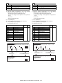
(2) First copy time
Account control
Yes 500 accounts
Conditions: A4 or 8.5"x11" from front tray of PPC, with polygon
motor running.
Process control
Yes
Tandem copy
Yes (via network)
(The AR-P20/P21 or the
AR-NC7/NC8 is required.)
Document glass *1
DSPF
*1: During OC mode
AR-M351U/M355U
Less than 4.9
seconds
Less than 6.0
seconds
AR-M451U/M455U
Less than 4.4
seconds
Less than 5.3
seconds
Tab copy
No
Book copy
Yes
Irregular original size input Yes
Irregular paper size input
AR-M351U/M451U, AR-M355U/M455U SPECIFICATIONS 3 - 7
Yes
Special
function
Margin shift
Yes
3. B/W Scanner Module (DSPF)
Edge erase/Center erase
Yes
(1) Form
Dual page copying
Yes
Covers/Inserts
Yes
Transparency insert
Yes
Centering
No
Multi shot (Nin1)
Yes (2 in 1 / 4 in 1)
(Centering: Yes)
Card shot
Yes
Pamphlet copy
Yes (Centering: Yes)
2-sided copy orientation
change
Yes
Job build
Yes (max.10000 sheets)
Negative image
Yes
Shading
No
Mirror image
Yes
Multi-page enlargement
No
Repeat
No
Date stamp
Yes
Stamp
Yes
Character stamp
Yes
Page stamp
Yes
Yes: Standard Function
No: Not provided
Scanner (Document glass) / DSPF standard
Operation panel integral type
(common hardware for all the destinations)
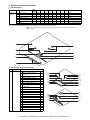
(2) Resolution / Gradation
Reading resolution (dpi)
Copy mode
Magnification
25 - 99
100
101 - 200
OC
600x600
600x600
600x600
OC
600x600
600x600
600x600
(High speed):
Text/Auto
OC
600x600
600x300
600x600
(High speed):
Others
DSPF/SPF
600x300
600x300
600x600
(standard)
DSPF/SPF
600x600
600x600
600x600
(high quality)
Input and transmitting resolution (dpi)
FAX transmit mode and scanner/fax multicasting mode
Selection
Standard
Fine
Super fine
mode
Input
600 x391.2 600x391.2 600x391.2
resolution: OC
Input
600x300
600x300
600x300
resolution:
DSPF
Transmitting
203.2x97.8 203.2x195.6 203.2x391
resolution
Internet-FAX
Transmitting
200x100
200x200
200x400
resolution
Scanner mode
Selection
Standard
Fine
Super fine
mode
Input
600x391.2 600x391.2 600x391.2
resolution: OC
Input
600x300
600x300
600x300
resolution:
DSPF
Transmitting
200x200
300x300
400x400
resolution
Reading level
256 tones
Exposure lamp
Electrodeless xenon lamp
Output level
Binary
201 - 400
600x600
600x600
–
–
–
600x600
–
-
–
-
–
Ultra fine
600x391.2
600dpi
sending
–
600x300
–
406.4x391
–
400x400
600x600
Ultra fine
–
600x600
–
600x300
–
600x600
–
(3) Document Glass
Reading area
Original
alignment
Original size
detection
Sizes to be
detected
297 x 431.8 (mm)
11.7" x 17"
Left edge / Rear corner alignment
Provided
(Standard size only)
Automatic (one detection unit to be used with
software modification by destination)
Inch-1
11" x 17", 8.5" x 14",
8.5" x 11", 8.5" x 11"R,
5.5" x 8.5"
Inch-2
11" x 17", 8.5" x 13",
8.5" x 11", 8.5" x 11"R,
5.5" x 8.5"
AB-1
A3, B4, A4, A4R, B5, B5R, A5
AB-2
A3, A4, A4R, A5, B5, B5R,
216 x 330 mm
AB-3
8K, A4, A4R, A5, B4, 16K,
16KR
AR-M351U/M451U, AR-M355U/M455U SPECIFICATIONS 3 - 8
OR guide
display
Rear left side
(Print display)
Left side OR
guide
(Print display)
Interior side OR
guide
(Print display)
Original reference position "
"
(From the Interior side)
5-1/2, A5R, B5R, A4R/A5,
8.5", B4R/B5, 11", A3R/A4
(From the left side)
5-1/2, A5, B5, A4/A5R, 8-1/2,
B5R, 11", A4R, 13", 14", B4R,
A3R, 17"
Interior side OR Book marks are at A4 and
guide
8-1/2 positions.
The position available to attach the staple
position guide label when the optional finisher
(desktop console type) is equipped.
(4) DSPF/SPF
Type
DSPF
One-scan-dual-side scanning
method DSPF with OC
integrated
45 opm
22.5 opm
Scan speed Standard mode
High quality mode
Original
Center alignment
alignment
Original size A3, B4, A4, A4R, B5, B5R, A5, A5R
11"x17", 8.5"x14", 8.5"x13", 8.5"x11", 8.5"x11"R,
5.5"x8.5", 5.5"x8.5"R, 8K, 16K, 16KR
(Long size original up to 800mm in FAX, e-mail and
iFAX mode)
Original
50~128g/m², 15~34lbs
paper
weight
Original
Max. 50 sheets
stack
(Max. 30 sheets for A3, B4,11" x 17",8.5" x 14")
capacity
(Max. 15 sheets for A3, B4, 11" x 17", 8.5" x 14"
over 105g/m²)
or, Total thickness less than
Max. 6.5mm (at 50 to 80g/m², 15 to 21lbs)
Max. 5.0mm (at 80 to 128g/m², 21 to 34lbs)
Not
Transparency film, secondary original paper,
transportable tracing paper, carbon paper, thermal paper,
original type original with crumple/crimp/rip,
original with attachment/clipping,
original with many punch holes
(with 2 or 3 holes acceptable),
original preprinted with ink-ribbon,
Documents with considerable curl.
Original size Provided
detection
Sizes to be Automatic (one detection unit to be used with
detected
software modification by destination)
Inch-1
11" x 17", 8.5" x 14",
8.5" x 11", 8.5" x 11"R,
5.5" x 8.5", A4, A3
Inch-2
11" x 17", 8.5" x 13",
8.5" x 11", 8.5" x 11"R,
5.5" x 8.5", A4, A3
AB-1
A3, B4, A4, A4R, B5, B5R,
A5, A3, 8.5" x 11", 11" x 17"
216 x 330 mm
AB-2
A3, B4, A4, A4R, B5, B5R,
A5, 8.5" x 11", 11" x 17",
216 x 330 mm
AB-3
8K, A4, A4R, B4, 16K, 16KR,
8.5" x 11", 216 x 330 mm
Original tray Center of the tray
guide
(inscribed symbol)
display
Original Guide
(inscribed symbol)
Original reference position
" " Original face-down
placement indication " "
(From Center)
B5R, A4R/A5, 8.5",
B4R/B5, 11", A3R/A4
The position available to attach the staple position
guide label when the optional finisher (desktop
console type) is equipped.
(5) Power Source
Supplied from the main unit
(6) Dimensions
External dimensions
(WxDxH)
Occupied space
dimensions (WxD)
Weight
32.4" x 23.9" x 7.48"
(824 x 606 x 190 mm)
37.2" x 24.4" (945 x 619 mm)
(When the tray is extended)
DSPF: Approx. 46.3 lbs (21.0 kg)
(7) Display device at scanner part
Type
Display dot number
LCD operating
dimension
LCD back-light
LCD brightness
adjustment
Dot map LCD, touch panel
640 x 240 dots (dot pitch 0.24x0.24 mm)
153.5 x 57.5 mm
Fluorescent tube method
Provided
(8) Key
Mode
Job status key
selection area Document filing key
(* online display LED/data in-memory display
LED)
Image send key
(busy display LED/data in-memory display LED)
Copy mode key
User definition key
Basic input
Start key
area
CA key
10-key
Clear key
∗ key
#/P key
* For printer
(9) Touch sense method
Resistive film method
(10) Used character in the LCD
Dot
Bold display
8 x 16 , 16 x 16 dots
O
4. Rack for Scanner
(1) Dimensions
Strength
Weight
60 kg
Approx. 16.3 (7.4 kg)
AR-M351U/M451U, AR-M355U/M455U SPECIFICATIONS 3 - 9
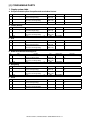
[4] CONSUMABLE PARTS
1. Supply system table
A. European Subsidiary/East Europe/Russia/Australia/New Zealand
No.
Item
Content
1 Toner Cartridge (Black) Toner CA with IC Chip
(Toner; Net Weight 750g)
2 Developer (Black)
Developer
(Developer; Net Weight 500g)
3 Drum
Drum
Life
350K
(35K x 10)
1,000K
(100K x 10)
200K
Model name
AR-455LT
Life
350k
(35k x 10)
1,000k
(100K x 10)
200k
Model name
AR-455ET
Life
350K
(35K x 10)
1,000K
(100K x 10)
200K
Model name
AR-455CT
Life
350K
(35K x 10)
1,000k
(100K x 10)
200k
Model name
AR-455ET
Model name
AR-455CT-C
x1
Life
350K
(35K x 10)
1,000K
(100K x 10)
200k
x1
Life
35k
Model name
AR-456ST-C
x1
100k
AR-455SD-C
x1
200k
AR-455DR-C
x 10
x 10
x1
Remarks
*Life: A4 size at Area Coverage
6%
AR-455LD
AR-455DM
B. Taiwan (Aurora)
No.
Item
Content
1 Toner Cartridge (Black) Toner CA with IC Chip
(Toner; Net Weight 750g)
2 Developer (Black)
Developer
(Developer; Net Weight 500g)
3 Drum
Drum
x 10
x 10
x1
Remarks
*Life : A4 size at Area Coverage
6%
AR-455LD
AR-455DM
C. Asia
No.
Item
Content
1 Toner Cartridge (Black) Toner CA with IC Chip
(Toner; Net Weight 750g)
2 Developer (Black)
Developer
(Developer; Net Weight 500g)
3 Drum
Drum
x 10
x 10
x1
Remarks
*Life: A4 size at Area Coverage
6%
AR-455CD
AR-455DR
D. Middle East/Africa/Israel/Philippines
No.
Item
Content
1 Toner Cartridge (Black) Toner CA with IC Chip
(Toner; Net Weight 750g)
2 Developer (Black)
Developer
(Developer; Net Weight 500g)
3 Drum
Drum
x 10
x 10
x1
Remarks
*Life : A4 size at Area Coverage
6%
AR-455CD
AR-455DR
E. Hong Kong
No.
Item
Content
1 Toner Cartridge (Black) Toner CA with IC Chip
(Toner; Net Weight 750g)
2 Developer (Black)
Developer
(Developer; Net Weight 500g)
3 Drum
Drum
x 10
x 10
Remarks
*Life : A4 size at Area Coverage
6%
AR-455CD-C
AR-455DR-C
F. China
No.
Item
Content
1 Toner Cartridge (Black) Toner CA with IC Chip
(Toner; Net Weight 750g)
2 Developer (Black)
Developer
(Developer; Net Weight 500g)
3 Drum
Drum
AR-M351U/M451U, AR-M355U/M455U CONSUMABLE PARTS 4 - 1
Remarks
*Life : A4 size at Area Coverage
6%
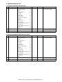
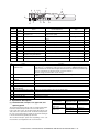
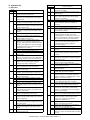
2. Maintenance parts list
A. Europe/Australia/New Zealand/Taiwan
No.
Item
1 200K PM kit
2
Staple cartridge
Content
Cleaner blade
Drum separation pawl
MC unit *1
Toner receiving seal
Side malt F
Side malt R
Transfer roller
Discharger plate
Paper dust removing unit
DV blade
DV side seal F
DV side seal R
Upper heat roller
Fusing separation pawl (Upper)
Lower heat roller
Fusing separation pawl (Lower)
Cleaning roller
Bearing
Staple cartridge
3
Staple cartridge
Staple cartridge
Life
200K
Model name
Remarks
AR-451KA *1: Screen grid, charging plate, MC
cleaner unit are included.
x1
x4
x1
x1
x1
x1
x1
x1
x1
x1
x1
x1
x1
x4
x1
x2
x1
x2
x3
3000 times x 3
AR-SC1
x3
5000 times x 3
AR-SC2
Cartridge for AR-FN4
Common with cartridge for AR-FN6
Common with cartridge for AR-FN7
Note: The other maintenance parts which are not listed above are registered as service parts.
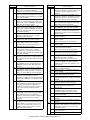
B. Agency/Asia/Middle East/Africa/Latin America
No.
Item
1 200K PM kit
2
Staple cartridge
Content
Cleaner blade
Drum separation pawl
MC unit *1
Toner receiving seal
Side malt F
Side malt R
Transfer roller
Discharger plate
Paper dust removing unit
DV blade
DV side seal F
DV side seal R
Upper heat roller
Fusing separation pawl (Upper)
Lower heat roller
Fusing separation pawl (Lower)
Cleaning roller
Bearing
Staple cartridge
3
Staple cartridge
Staple cartridge
Life
200K
Model name
Remarks
AR-451KA *1: Screen grid, charging plate, MC
cleaner unit are included.
x1
x4
x1
x1
x1
x1
x1
x1
x1
x1
x1
x1
x1
x4
x1
x2
x1
x2
x3
3000 times x 3
AR-SC1
x3
5000 times x 3
AR-SC2
Cartridge for AR-FN4
Common with cartridge for AR-FN6
Common with cartridge for AR-FN7
Note: The other maintenance parts which are not listed above are registered as service parts.
AR-M351U/M451U, AR-M355U/M455U CONSUMABLE PARTS 4 - 2
C. Hong Kong
No.
Item
1 200K PM kit
2
Staple cartridge
Content
Cleaner blade
Drum separation pawl
MC unit *1
Toner receiving seal
Side malt F
Side malt R
Transfer roller
Discharger plate
Paper dust removing unit
DV blade
DV side seal F
DV side seal R
Upper heat roller
Fusing separation pawl (Upper)
Lower heat roller
Fusing separation pawl (Lower)
Cleaning roller
Bearing
Staple cartridge
3
Staple cartridge
Staple cartridge
Life
Model name
Remarks
x1
200K
AR-451KA *1: Screen grid, charging plate, MC
cleaner unit are included.
x4
x1
x1
x1
x1
x1
x1
x1
x1
x1
x1
x1
x4
x1
x2
x1
x2
x 3 3000 times x 3
AR-SC1
Cartridge for AR-FN4
Common with cartridge for AR-FN6
x 3 5000 times x 3
AR-SC2
Common with cartridge for AR-FN7
Note: The other maintenance parts which are not listed above are registered as service parts.
D. China
No.
Item
1 200K PM kit
2
Staple cartridge
Content
Cleaner blade
Drum separation pawl
MC unit *1
Toner receiving seal
Side malt F
Side malt R
Transfer roller
Discharger plate
Paper dust removing unit
DV blade
DV side seal F
DV side seal R
Upper heat roller
Fusing separation pawl (Upper)
Lower heat roller
Fusing separation pawl (Lower)
Cleaning roller
Bearing
Staple cartridge
3
Staple cartridge
Staple cartridge
Life
Model name
Remarks
x1
200K
AR-451KA *1: Screen grid, charging plate, MC
cleaner unit are included.
x4
x1
x1
x1
x1
x1
x1
x1
x1
x1
x1
x1
x4
x1
x2
x1
x2
x 3 3000 times x 3
AR-SC1
Cartridge for AR-FN4
Common with cartridge for AR-FN6
x 3 5000 times x 3
AR-SC2
Common with cartridge for AR-FN7
Note: The other maintenance parts which are not listed above are registered as service parts.
AR-M351U/M451U, AR-M355U/M455U CONSUMABLE PARTS 4 - 3
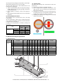
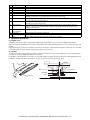
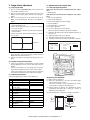
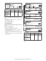
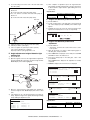
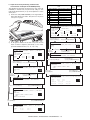
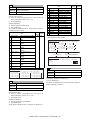
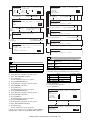
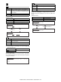
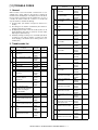
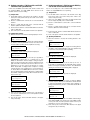
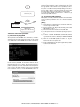
2. Production number identification
C. Developer cartridge
The lot number is of 8 digit, and each digit indicates as follows.
The lot number, printed on the front side flange, is composed of 10
digits, each digit showing the following content:
1
1
2
3
4
5/6
7
8/9
10
2
3
4
5
6
7
8
9
10
Number
For this model, this digit is 2.
Alphabet
Indicates the model conformity code. T for this model.
Number
Indicates the end digit of the production year.
Number or X, Y, Z
Indicates the production month.
X stands for October, Y November, and Z December.
Number
Indicates the production day on the month.
Number or X, Y, Z
Indicates the month of packing.
X stands for October, Y November, and Z December.
Number
Indicates the day of the month of packing.
Alphabet
Indicates the production factory. "A" for Nara Plant.
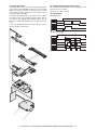
B. Toner cartridge
The lot number is of 7 digits, and each digit indicates as follows.
The lot number shall be printed in the position shown in the figure.
1
2
3
4
5
6
The lot number shall be printed on the bag.
1
2
1
3
4
5
6
7
8
Alphabet
Indicates the production factory.
Number
Indicates the production year.
Number
Indicates the production month.
Number
Indicates the production day.
Hyphen
Number
Indicates the production lot.
2
3/4
5/6
7
8
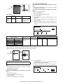
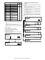
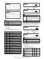
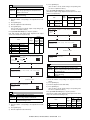
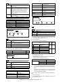
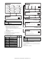
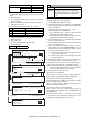
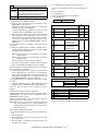
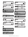
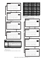
3. Environmental conditions
A. Operating conditions
30
85%
85
Humidity (%)
A. Drum cartridge
35
60%
7
20
3
4
5/6
7
Version number (A - sequentially revised)
Numeral figure
Indicates the end digit of the production year.
Alphabet
Indicates the production factory. (B for SOCC)
Destination code
Numeral figures
Indicates the production day.
Numeral figure or X, Y, Z
Indicates the production month.
X stands for October, Y November, and Z December.
Serial No. attachment
10
35
Temperature
(Without dew condensation)
B. Storage conditions
90
Humidity (%)
1
2
20
-10
Temperature
40
(Without dew condensation)
Serial No. attachment
Heat seal
Aluminum bag
AR-M351U/M451U, AR-M355U/M455U CONSUMABLE PARTS 4 - 4
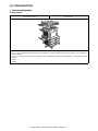
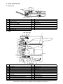
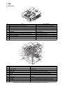
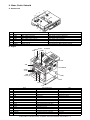
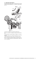
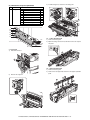
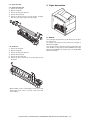
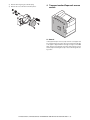
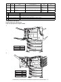
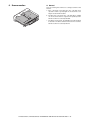
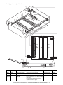
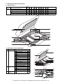
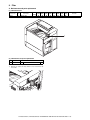
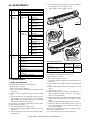
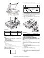
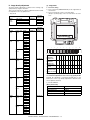
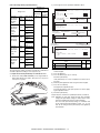
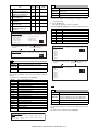
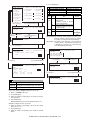
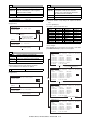
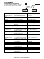
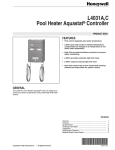
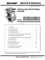
[5] EXTERNAL VIEWS AND INTERNAL STRUCTURES
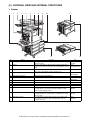
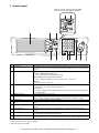
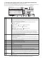
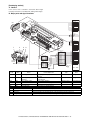
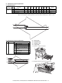
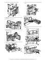
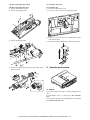
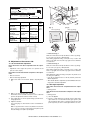
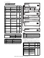
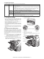
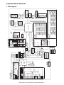
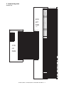
1. Exterior
1
2
3
4
5
6
7
8
9
10
12
13
11
No.
1
Name
2
Exit tray
3
Automatic document feeder
4
Duplex module
Function
This tray can also be used for special papers including
transparency film.
The tray is extendable to support large size paper. Extend the tray
when 11" x 17", 8-1/2" x 14", 8-1/2" x 13", A3 or B4 paper is being
used.
This automatically feeds and scans multiple sheet originals. Both
sides of two-sided originals can be scanned at once.
Module for two-sided printing
5
6
Upper paper output area
Upper exit tray extension
Finished sheets are deposited here.
Provides support for large size paper.
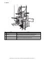
7
8
9
10
11
Operation panel
Front cover
Power switch
Paper tray 1
Stand/3 x 500 sheet paper drawer
12
Stand/MPD & 2000 sheet paper drawer
13
Multi purpose drawer
Bypass tray
–
Open to add toner.
Press to turn power on and off.
–
This paper feed unit contains an upper multi-purpose drawer and
two lower drawers each of which can hold a maximum of 500
sheets of 20 lbs. (80 g/m2) paper.
This paper feed unit contains an upper multi-purpose drawer and a
lower drawer which can hold a maximum of 2000 sheets of 20 lbs.
(80 g/m2) paper.
Up to 500 sheets of 20 lbs. (80 g/m2) paper can be loaded. Also
special papers such as envelopes (standard sizes only) and
postcards can be set.
Note
Option
(AR-DU4)
Option
(AR-DU4/AR-TE3)
–
Option
(AR-DU3/DU4)
–
Option
(AR-AR-TE4)
–
–
–
–
Option
(AR-D27)
Option
(AR-D28)
Option
(AR-MU2)
AR-M351U/M451U, AR-M355U/M455U EXTERNAL VIEWS AND INTERNAL STRUCTURES 5 - 1
2. Interior
1
2
4
3
5
No.
1
2
3
6
Name
Duplex module side cover
Side cover latch
Fusing unit
Function
Open when a misfeed has occurred in the duplex module.
Push up to open the side cover when a misfeed has occurred in the main unit.
Lift up to open the side cover when a misfeed has occurred in the main unit.
4
5
Toner cartridge (drum/toner cartridge)
Photoconductive drum
CAUTION: The fusing unit is hot. Take care in removing misfed paper.
The toner cartridge must be replaced when indicated on the operation panel.
Images are formed on the photoconductive drum.
6
Cartridge lock lever
NOTE: Do not touch or damage the photoconductive drum.
When replacing the drum, toner or developer cartridge, turn down this lever and pull it out.
AR-M351U/M451U, AR-M355U/M455U EXTERNAL VIEWS AND INTERNAL STRUCTURES 5 - 2
3. Operation panel
When the printer expansion kit (with HDD)
print server card (with HDD) is installed.
2
1
No.
1
2
Name
Touch panel
Mode select keys and indicators
2
3
4
5
6
3
7
8
9
10
11
Function
The machine status, messages and touch keys are displayed on the panel. The document filing,
copy, network scanner*2, and fax*3 functions are used by switching to the screen for the desired
function.
Use to change modes and the corresponding display on the touch panel.
[PRINT] key/[DOCUMENT FILING] key*1
Press to select the print/document filing*1 mode.
[IMAGE SEND] key/LINE indicator/DATA indicator
Press to change the display to network scanner mode*2 or fax mode*3.
3
PRINT mode indicators
[COPY] key
Press to select the copy mode.
READY indicator
Print data can be received when this indicator is lit.
DATA indicator
4
5
[JOB STATUS] key
[CUSTOM SETTINGS] key
6
7
Numeric keys
[ ] key ([ACC.#-C] key)
8
[#/P] key
9
[C] key (Clear key)
10
[START] key
11
[CA] key (Clear all key)
Lights up or blinks when print data is being received. Also lights up or blinks when printing is
being performed.
Press to display the current job status.
This is used to store, edit, and delete user names and folder names for the document filing
function*1, and to configure the key operator programs and printer configuration settings.
Use to enter numeric values for various settings.
This key is used in copy mode, document filing mode*1, network scanner mode*2, and fax
mode*3.
This is used as a program key when using the copy function, and to dial when using the fax
function*3.
This key is used in copy mode, document filing mode*1, network scanner mode*2, and fax
mode*3.
Use this key to start copying in copy mode, scan a document in network scanner mode*2, or
scan a document for transmission in fax mode*3.
This key is used in copy mode, document filing mode*1, network scanner mode*2, and fax
mode*3. Use the key to cancel settings and perform an operation from the initial machine state.
*1: When the printer expansion kit (with HDD)/print server card (with HDD) is installed.
*2: When the network scanner option is installed.
*3: When the fax option is installed.
AR-M351U/M451U, AR-M355U/M455U EXTERNAL VIEWS AND INTERNAL STRUCTURES 5 - 3
4. Job status screen (common to print, copy, fax, network scan and Internet fax)
This screen is displayed when the [JOB STATUS] key on the operation panel is pressed.
This screen can be used to display the "JOB QUEUE" (showing stored jobs and the current job) or the "COMPLETE" job list (showing finished jobs). This screen can be used to check jobs, interrupt a job in progress to perform another job, and cancel a job.
1
"JOB QUEUE" screen
JOB QUEUE
SETS / PROGRESS
1/1
020 / 001
COPYING
COPY
020 / 000
PAPER EMPTY
Suzuki
020 / 000
WAITING
066211221
002 / 000
WAITING
4
"COMPLETE"
job screen
JOB QUEUE
JOB QUEUE
COMPLETE
COMPLETE
DETAIL
DETAIL
PRIORITY
STOP/DELETE
5
CALL
INTERNET-FAX
INTERNET-FAX
FAX JOB
E-MAIL/FTP
3
2
STATUS
COPY
PRINT JOB
No.
Name
1 Job list
*1
6
7
8 9 10
11
Function
The displayed jobs in the job list are themselves operation keys. To cancel printing or to give a job the highest print
priority, touch the relevant job key to select the job and execute the desired operation using the keys described in 8
and 9.
This shows the current job and the jobs waiting to be run. The icons to the left of the jobs in the queue show the job
mode. The document filing reprint job icon is highlighted.
Note that the icon does not become highlighted during retransmission of a fax/image transmission job.
Print mode
Copy mode
E-MAIL/FTP mode
Scan to e-mail job
Fax mode
Fax send job
Internet Fax mode
i-Fax send job
Scan to FTP job
Fax reception job
i-Fax reception job
Scan to Sharpdesk job
PC-Fax send job
PC-Internet Fax send job
*1: "PAPER EMPTY" in the job status display
When a job status display indicates "PAPER EMPTY", the specified paper size for the job is not loaded in any of the
trays.
In this case, the job will be suspended until the required paper is loaded. Other stored jobs will be printed (if
possible) until the required paper is loaded. (Other jobs will not be printed if the paper runs out during printing.) If
you need to change the paper size because the specified paper size is not available, touch the current job key to
select it and then touch the [DETAIL] key described in 10.
2 Mode select key
This switches the job list display between "JOB QUEUE" and "COMPLETE".
"JOB QUEUE": Shows stored jobs and the job in progress.
"COMPLETE": Shows finished jobs.
Files saved using the "FILE" and "QUICK FILE" functions and finished broadcast transmission jobs appear as keys
in the finished job screen.
The "FILE" or "QUICK FILE" job keys in the finished job screen can be touched, followed by the [CALL] key, to call
up a finished job and print or transmit it. A finished broadcast transmission job key can be touched followed by the
[DETAIL] key to check the result of the transmission.
3 [PRINT JOB] key
This displays the print job list of print mode (copying, printing, fax reception, Internet fax reception, and self printing).
4 [E-MAIL/FTP] key
This displays the transmission status and finished jobs of scan mode (Scan to e-mail, Scan to FTP, and Scan to
SharpDesk) when the network scanner option is installed.
5 [FAX JOB] key
This displays the transmission/reception status and finished jobs of fax mode (fax and PC-Fax) when the fax option
is installed.
6 Display switching keys Use to switch the page of the displayed job list.
7 [INTERNET-FAX] key This displays the transmission/reception status and finished jobs of Internet fax mode and PC Internet fax mode
when the network scanner option is installed.
8 [STOP/DELETE] key Use to cancel or delete the current job or delete the stored job. Note that printing of received faxes and received
Internet faxes cannot be canceled or deleted.
9 [PRIORITY] key
Touch this key after selecting a stored job in this [JOB QUEUE] list to print the job ahead of the other jobs.
Note that a job in progress cannot be interrupted if it is an interrupt copy job or if it is a list print job.
10 [DETAIL] key
This shows detailed information on the selected job. Files saved using the "FILE" and "QUICK FILE" functions and
finished broadcast transmission jobs appear as keys in the finished job screen. A Quick File in the finished job
screen or the [Filing] key can be touched, followed by the [CALL] key, to call up a finished job and print or transmit it.
A finished broadcast transmission job key can be touched followed by the [DETAIL] key to check the result of the
transmission.
11 [CALL] key
When this key is touched after selecting a job in the COMPLETE job status screen (a job stored using the FILE or
QUICK FILE keys of the document filing function), the "JOB SETTINGS" menu screen appears to let you resend or
reprint the finished job.
AR-M351U/M451U, AR-M355U/M455U EXTERNAL VIEWS AND INTERNAL STRUCTURES 5 - 4
5. Cross sectional view
A. Scanner unit
17 SPOD
16
1
2
3 SPPD
4 SPED
6
5
7
15
14
No.
1
2
3
4
5
6
7
8
9
13
12 11 10
Name
CIS unit
Original resist roller
Original resist front sensor (SPPD)
Original set sensor (SPED)
Original take-up sensor
Original length sensor 1 (SPLS1)
Original length sensor 2 (SPLS2)
CCD/lens unit
Original feed roller
8
9
No.
10
11
12
13
14
15
16
17
Name
Copy lamp base unit
No. 1 mirror
Copy lamp (Xenon)
Mirror base unit
No. 3 mirror
No. 2 mirror
Original exit roller
Original exit sensor
B. Engine
POD1 POD2 POD3
21
22
23
24
20
18
15
19
16
17
4
26
3
2
1
8
6
9
5
PPD1
10
25
11
12
No.
1
2
3
4
5
6
7
8
9
10
11
12
13
Name
OPC drum
Main charger
Cleaning blade
LSU
Developing unit
Magnet roller
Toner hopper
Transfer roller
Resist roller
Paper transport roller
Machine tray (Paper tray1) paper feed roller
Machine tray (Paper tray1) separation roller
Machine tray (Paper tray1) take-up roller
13
PED TUD 7
No.
14
15
16
17
18
19
20
21
22
23
24
25
26
14
Name
Machine tray (Paper tray1) rotating plate
Upper heat roller
Pressure roller
Heater lamp
Thermistor (RTH1 / RTH2)
Thermostat
Fusing back roller
Reverse gate
Paper exit roller
Full detection lever
Printer control PWB
Power supply unit
Cleaning roller
AR-M351U/M451U, AR-M355U/M455U EXTERNAL VIEWS AND INTERNAL STRUCTURES 5 - 5
6. Switch, Sensor
A. Scanner unit
4
6
5
7
3
2
1
8
12
9
11
10
1
2
3
4
5
6
7
8
9
10
11
12
Code
SPPD
SCOV
SPED
OCSW
ORS-LED
SPLS1
SPLS2
SPFVR
ORS-PD
SOCD
SPOD
MHPS
Name
SPF original resist front sensor
SPF paper feed cover sensor
SPF original set sensor
OC open/close sensor
Original size sensor PWB (Light emitting side)
SPF original length sensor 1
SPF original length sensor
SPF original width detection volume PWB
Original size sensor PWB (Light receiving side)
SPF open/close sensor
SPF original exit sensor
Mirror home position sensor
Active condition
B. Engine
5.POD3
4.POD2
2.DSW-L
3.POD1
7.TCS
8.LUD
6.PPD1
10.MAIN SW
1.DSW-F
9.PED
Code
1
2
3
4
5
6
7
8
9
10
DSW-F
DSW-L
POD1
POD2
POD3
PPD1
TCS
LUD
PED
MAIN SW
Function/Operation
Front door open/close detection
Left door open/close detection
Paper exit detection
Paper exit detection
Paper exit detection Full
Paper transport detection
Toner concentration sensor
Paper feed cassette upper limit detection
Paper feed cassette paper empty detection
Power switch
Active condition
H= Door open
H=Door open
L= Paper detection
L= Paper detection
L= Paper detection
L= Paper detection
H= Upper limit detection
L= Paper empty detection
AR-M351U/M451U, AR-M355U/M455U EXTERNAL VIEWS AND INTERNAL STRUCTURES 5 - 6
7. PWB
A. Scanner unit
3
2
1
13
6
4
5
12
11
7
8
10
9
No.
1
2
3
4
5
6
7
8
9
10
11
12
13
Name
SPF control PWB
Original size detection PWB (Light emitting side)
CCD PWB (in lens unit) (The lens unit cannot be disassembled.)
SPF original width detection volume PWB
MFP operation PWB
Scanner control PWB
LVDS PWB
Original size sensor (Light receiving side)
CIS unit (in CIS unit) (The CIS unit cannot be disassembled.)
CIS interface PWB (in CIS unit) (The CIS unit cannot be disassembled.)
Scanner interface PWB
CIS control PWB
CL inverter PWB
Function/Operation
SPF control
Original size detection when using the table glass
Image scan (Table glass/SPF surface)
SPF original width detection
Panel operation control
Scanner unit control
LCD signal relay
Original size detection when using the table glass
Image scan (SPF back surface)
CIS signal AD conversion process
Scanner unit and connection of scanner control PWB
CIS unit control and image process
Inverter for copy lamp
B. Engine
1
4
2
5
7
11
8
6
10
13
9
12
No.
1
2
3
4
5
6
7
8
9
10
11
12
13
Name
PRT controller
PCU PWB
Power supply unit
LD PWB (Inside LSU)
Mother PWB
Reactor PWB (200V only) / Filter PWB (Taiwan only)
BD PWB
High voltage resistor PWB
Cassette detection PWB
Drawer PWB
High voltage PWB
Fuse PWB
Relay PWB
3
Function/Operation
Image process, image data communication control
Overall control of the machine and options
DC power supply
Laser ON control (Inside LSU: LSU cannot be disassembled.)
Signal interface between PCU and the controller
Noise filter
Laser control (Inside LSU: LSU cannot be disassembled.)
High voltage load adjustment
Paper cassette control
Fan control
High voltage power supply
Protection of the machine when an abnormal power is supplied.
HDD back up
AR-M351U/M451U, AR-M355U/M455U EXTERNAL VIEWS AND INTERNAL STRUCTURES 5 - 7
8. Motor, Clutch, Solenoid
A. Scanner unit
5
4
3
1
2
7
6
No.
1
2
3
4
5
6
7
SPFM
SRRC
SPFC
SDSS
MIRM
SPFS
STMPS
Name
SPF motor
SPF original resist clutch
SPF original feed clutch
SPF original stopper solenoid
Mirror motor
SPF original feed solenoid
Stamp solenoid
Function/Operation
Original transport in SPF scan
SPF original scan timing adjustment
SPF original feed roller drive
SPF original stopper gate drive
Mirror base copy lamp base drive
SPF original feed unit drive
Finish stamp drive (Option AR-SU1 required)
B. Engine
10.CFM2
3.POM
13.PSPS
16.CNTFAN
6.VFM2
17.PM
1.DM
15.HDDFAN
14.RRC
12.TRC
2.MM
11.CPFC
7.VFM1
7.VFM1
5.LUM
8.CFM1
4.TM
Code
1
2
3
4
5
6
7
8
10
11
12
13
14
15
16
17
DM
MM
POM
TM
LUM
VFM2
VFM1
CFM1
CFM2
CPFC
TRC
PSPS
RRC
HDDFAN
CNTFAN
PM
Function/Operation
Drum motor
Main motor
Paper exit motor
Toner motor
Lift-up motor
Heat exhaust fan motor
Cooling fan motor
Suction fan motor
Ozone exhaust fan motor
Paper cassette paper feed clutch
Paper transport clutch
Separation solenoid
Resist roller clutch
Cooling fan motor (for HDD)
Cooling fan motor (for controller)
Polygon motor
Type
Brushless motor
Brushless motor
Stepping motor
Synchronous motor
Synchronous motor
Fan motor
Fan motor
Fan motor
Fan motor
Fan motor
Fan motor
Polygon motor
AR-M351U/M451U, AR-M355U/M455U EXTERNAL VIEWS AND INTERNAL STRUCTURES 5 - 8
[6] UNPACKING AND INSTALLATION
1. Installing procedure flowchart
There are many combinations between this machine and option
units. For installing option units, observe the following procedures
for efficiency.
To install the devices effciently, follow the procedure below.
Some peripheral devices may have been installed as standard
devices depending on the main unit model.
Part of descriptions and illustrations may be different.
Scanner/document feeder device
Finishing device
Duplex/bypass device
Finishing device
Main unit
Duplex device
Finishing device
Main unit
Paper feeding device
Paper feeding device
* To install the AR-MU2, the optional exclusive-use desk is required.
Start of installation
Main unit, paper feeding
device, and power supply
unit.
Controller board,
facsimile unit or other
electric devices
installed?
AR-MU2
AR-D27
AR-D28
Yes
Main unit
No
[Electrical setting/adjustment]
Install duplex/pypass device.
Duplex/bypass
device installed?
Yes
AR-DU3
AR-DU4
No
1) Installation of driver software, setting,
and operation check
Main unit/AR-EF3/AR-FX12/AR-P20/AR-P21
AR-NC7/AR-NC8/AR-PK6/AR-NS3
2) Paper guide position adjustment/off center adjustment
Install finishing device.
Finishing device
installed?
Install controller board,
facsimile unit or other electric
devices.
AR-FX12/AR-MM9
AR-P20
AR-P21
AR-NC7
AR-NC8
AR-PK6
AR-NS3
Extended memory
Yes
AR-MU2/AR-D27/AR-D28/
AR-DU3/AR-DU4
AR-MS1
AR-FN6
AR-FN7
AR-PN1A / B / C / D
End
No
When installing a paper feeding device or a duplex/bypass device, be sure to reattach
the rear cabinet, the AC inlet cover, and the harness cover of the main unit at the end
of installation as needed.
When installing a controller board, a facsimile unit, and other electric devices, be sure to install them
at a time.
Only off center adjustment is needed for AR-DU3.
∗ For installation of an option unit, refer to the Service Manual of the option unit.
AR-M351U/M451U, AR-M355U/M455U UNPACKING AND INSTALLATION 6 - 1
2. Note for installation place
Check the following items are included in the package.
Improper installation may damage this product. Please note the
following during initial installation and whenever the machine is
moved.
1) The machine should be installed near an accessible power
outlet for easy connection.
2) Be sure to connect the power cord only to a power outlet that
meets the specified voltage and current requirements. Also
make certain the outlet is properly grounded.
• For the power supply requirements, see the name plate of
the main unit.
3) Do not install your machine in areas that are:
• damp, humid, or very dusty
• exposed to direct sunlight
• poorly ventilated
• subject to extreme temperature or humidity
changes, e.g., near an air conditioner or heater.
4) Be sure to allow the required space around the machine for
servicing and proper ventilation.
11-13/16" (30cm)
23-5/8"
(60cm)
31-1/2"
(80cm)
(North America)
AR-M355U/M455U AR-M355U/M455U
+ AR-P20
+ AR-P21
Operating Manual (Copier/Key Operation)
–
Install Guide (PCL, PC)
–
CD-ROM (Printer)
–
CD-ROM (NIC)
Maintenance card/Maintenance case
Key Sheet (PRINT display)
AR-M355U/M455U
(Europe)
AR-M351U/M451U AR-M351U/M451U
+ AR-NC7
+ AR-NC8
Operating Manual (Copier/Key Operation) *1
CD-ROM (Printer) *2
–
CD-ROM (NIC)
Maintenance card/Maintenance case
Installation Report/Other
Key Sheet (PRINT display) *1
Key Sheet (PRINT
display)
Key Sheet (DOCUMENT FILING display) Key Sheet
(DOCUMENT
FILING display) *1
AR-M351U/M451U
*1: For the Europe model, this manual is included in the operation
manual kit for language support.
The standard language for the key sheet is English. To support local language, attach the key sheet.
*2: For the Europe model, two driver CD's are provided for language support.
23-5/8" (60cm)
B. AR-M351U/M451U (Except for Europe)
1) Release the joint, and remove the packing case.
3. Unpacking procedure
2) Remove the top pad, and open the electrostatic polyethylene
bag.
A. AR-M355U/M455U (North America),
AR-M351U/M451U (Europe)
Check the following items are included in the package.
AR-M351U/M451U AR-M351U/M451U
+ AR-NC7
+ AR-NC8
Operating Manual (Copier/Key Operation) *1
CD-ROM (Printer) *2
–
CD-ROM (NIC)
Maintenance card/Maintenance case
Installation Report/Other
Key Sheet (PRINT display) *1
Key Sheet (PRINT
display)
Key Sheet (DOCUMENT FILING display) Key Sheet
(DOCUMENT
FILING display) *1
AR-M351U/M451U
AR-M351U/M451U, AR-M355U/M455U UNPACKING AND INSTALLATION 6 - 2
3) Remove the cushioning materials from the right and left of the
front side.
4. Remove the locking tape
(AR-M355U/M455U (North America),
AR-M351U/M451U (Europe))
4) Remove the locking tape from the right and left sidesof the
tray.
Then, Remove the top of the carton and lower the plastic bag
covering the machine while the machine is still on the carton
base.
5) Remove the packing tape from the paper tray, pull out the
paper tray until it stops and remove it by tilting it upward.
5. Unpacking and installation of the
desk unit
6) One person must lift by the empty front tray pocket with the
right hand and steady the machine with the left hand placed at
the upper left of the machine.
The other person must lift with the right hand by using the lifting recess in the rear of the machine and also steady the
machine with the left hand as shown in the illustration.
Front side
Note: In advance to installation of the machine, the paper feed
option units (AR-D27/AR-D28/AR-MU2) should have been
installed.
A. AR-D28
<Before installation>
• Start installation after checking that the DATA and COMMUNICATION indicators on the operation panel are neither lit nor
blinking.
Rear side
Note: The center of gravity of the machine lies in the left side
when viewed from the Back of machine. When lifting the
machine, be careful not to drop it.
<Parts included>
Front mounting
plates: 2 pcs.
Rear mounting
plates: 2 pcs.
Screws (M4x6):
4 pcs.
Left adjuster: 1 pc.
Left paper guides: 2 pcs.
AR-M351U/M451U, AR-M355U/M455U UNPACKING AND INSTALLATION 6 - 3
Right paper guides: 2 pcs.
1) Turn off the main switch of the main unit of the printer.
Turn the main switch located on the front side of the printer to
the "OFF" position.
Then remove the power plug from the outlet.
4) Connect the main unit to the stand/paper drawer.
<1> Attach the rear mounting plates using a supplied screw for
each.
Rear mounting plate
"OFF"
Screw
Screw
Rear mounting plate
Rear
mounting plate
2) Attach the adjusters and adjust them.
<1> Insert the left adjusters to the stand/paper drawer.
<2> Turn the each adjusters to lower them until they touch the
floor.
Desk frame
Caution: Insert the rear mounting plates under the desk frame.
<2> Pull out the upper paper tray of the stand/paper drawer until it
stops and attach the front mounting plates using a supplied
screw for each.
Then, remove the lock of the paper tray and close the tray.
2
2
2
Front
mounting plate
1
2
Screw
∗ Be sure to attach the left adjuster to prevent overturning.
Caution: The lower tray cannot be pulled out unless the adjuster
is lowered to the specified position.
3) Put the main unit of the printer on the stand/paper drawer.
<1> Pull out the paper tray of the main unit until it stops and then
remove it by lifting both ends of the tray.
Front mounting
plate
Screw
<3> Reattach the paper tray of the main unit.
<2> Hold the main unit of the printer at the positions shown in the
illustration and put the main unit on the stand/paper drawer
so that the front side and the left side of the main unit are
aligned to those of the stand/paper drawer.
Front side
5) Connect the power supply I/F harness to the PCU PWB of the
main unit of the printer.
Rear side
<1> Remove the screw that fixes the harness cover of the main
unit of the printer and slide the harness cover up to remove it.
Process the harness cover as shown in the illustration.
Screw
Caution: For installation of the main unit, it must be held by two
persons and installed without haste.
Cut out.
Harness cover
AR-M351U/M451U, AR-M355U/M455U UNPACKING AND INSTALLATION 6 - 4
<2> Connect the power supply I/F harness connector (red, 22pin)
to CN11 (red connector) of the PCU PWB of the main unit of
the printer.
Connector
B. AR-D27
<Before installation>
• Start installation after checking that the DATA and COMMUNICATION indicators on the operation panel are neither lit nor
blinking.
CN11
Connect the connector (white, 4pin) of power supply I/F harness to the I/F connector (white, 4pin) of the main unit.
Remove the M4 screw shown in the illustration, insert the circle terminal of ground harness, and it fixes again.
<Parts included>
Front mounting
plates: 2 pcs.
Rear mounting
plates: 2 pcs.
Screws (M4x6):
4 pcs.
Left adjuster: 1 pc.
1) Turn off the main switch of the main unit of the printer.
Turn the main switch located on the front side of the printer to
the "OFF" position.
Then remove the power plug from the outlet.
<3> Reattach the power supply I/F harness cover to its original
position and fix it with the removed screw.
At this time, ensure that the power supply I/F harness are
arranged as shown in the illustration.
"OFF"
• Fix the harness securely to the wire saddle.
Screw
2) Attach the adjusters and adjust them.
<1> Insert the left adjusters to the stand/paper drawer.
Power supply
I/F harness
<2> Turn the five adjusters to lower them until they touch the
floor.
Harness cover
2
Wire saddle
Wire saddle
2
2
6) Attach the paper guides to the lower tray (large capacity tray)
and set the size.
Refer to "Setting and adjustment" described later.
∗ If another peripheral device must be installed, carry out the fol-
lowing step at the end of the installation work.
7) Adjust the position of the paper guides of the upper paper tray
of the stand/paper drawer.
Refer to "Setting and adjustment" described later.
8) Carry out the off center adjustment.
1
2
∗ Be sure to attach the left adjuster to prevent overturning.
Caution: The lower tray cannot be pulled out unless the adjuster
is lowered to the specified position.
3) Put the main unit of the printer on the stand/paper drawer.
<1> Pull out the paper tray of the main unit until it stops and then
remove it by lifting both ends of the tray.
AR-M351U/M451U, AR-M355U/M455U UNPACKING AND INSTALLATION 6 - 5
<2> Hold the main unit of the printer at the positions shown in the
illustration and put the main unit on the stand/paper drawer
so that the front side and the left side of the main unit are
aligned to those of the stand/paper drawer.
<3> Reattach the paper tray of the main unit.
Front side
5) Connect the power supply I/F harness to the PCU PWB of the
main unit of the printer.
Rear side
<1> Remove the screw that fixes the harness cover of the main
unit of the printer and slide the harness cover up to remove it.
Process the harness cover as shown in the illustration.
Screw
Caution: For installation of the main unit, it must be held by two
persons and installed without haste.
4) Connect the main unit to the stand/paper drawer.
<1> Attach the rear mounting plates using a supplied screw for
each.
Cut out.
Rear mounting plate
Harness cover
Screw
<2> Connect the power supply I/F harness connector (red, 22pin)
to CN11 (red connector) of the PCU PWB of the main unit of
the printer.
Screw
Rear mounting plate
Connector
Mounting plate
CN11
Desk frame
Caution: Insert the rear mounting plates under the desk frame.
<2> Pull out the upper paper tray of the stand/paper drawer until it
stops and attach the front mounting plates using a supplied
screw for each.
Then, remove the lock of the paper tray and close the tray.
Remove the locks of the middle tray and the lower tray similarly.
Connect the connector (white, 4pin) of power supply I/F harness to the I/F connector (white, 4pin) of the main unit.
Remove the M4 screw shown in the illustration, insert the circle terminal of ground harness, and it fixes again.
Front
mounting plate
Screw
Front mounting
plate
Screw
AR-M351U/M451U, AR-M355U/M455U UNPACKING AND INSTALLATION 6 - 6
<3> Reattach the harness cover to its original position and fix it
with the removed screw.
At this time, ensure that the power supply I/F harness is
arranged as shown in the illustration.
2) Put the main unit of the printer on the multi purpose drawer.
<1> Pull out the paper tray of the main unit until it stops and then
remove it by lifting both ends of the tray.
• Fix the harness securely to the wire saddle.
Screw
Power supply
I/F harness
Harness cover
<2> Hold the main unit of the printer at the positions shown in the
illustration and put the main unit on the multi purpose drawer
so that the front side and the left side of the main unit are
aligned to those of the multi purpose drawer.
Front side
Wire saddle
Wire saddle
6) Adjust the position of the paper guides of the upper paper tray
of the stand/paper drawer.
Refer to "Setting and adjustment" described later.
7) Carry out the off center adjustment.
Rear side
C. AR-MU2
Caution: For installation of the main unit, it must be held by two
persons and installed without haste.
3) Connect the main unit of the printer to the multi purpose
drawer.
<1> Attach the rear mounting plates using a supplied screw for
each.
Rear mounting plate
<Parts included>
Screw
Screw
Rear mounting plate
Front mounting plates: Rear mounting plates:
2 pcs.
2 pcs.
Screws (M4x8):
4 pcs.
1) Turn off the main switch of the main unit of the printer.
Turn the main switch located on the front side of the main unit
to the "OFF" position.
Then, remove the power plug of the main unit from the outlet.
Mounting
plate
Tray frame
Caution: Insert the mounting plate under the desk frame.
"OFF"
AR-M351U/M451U, AR-M355U/M455U UNPACKING AND INSTALLATION 6 - 7
<2> Pull out the paper tray of the multi purpose drawer until it
stops and attach the front mounting plates using a supplied
screw for each.
Then, remove the lock of the paper tray and close the tray.
<3> Remove the filament tape that secure the the power supply I/
F harness.
Front
mounting plate
Screw
5) Connect the harness to the main unit of the printer.
<1> Remove the screw that fixes the harness cover of the main
unit of the printer and then slide the harness cover up to
remove it.
Process the harness cover as shown in the illustration.
Front mounting plate
Screw
<3> Reattach the paper tray of the main unit of the printer.
Screw
Cut out.
4) Remove the multi rear cabinet.
<1> Remove the two screws that secure the multi rear cabinet.
Harness cover
Screw
<2> Connect the connector of the relay harness of the multi purpose drawer to the connector of the PCU PWB of the main
unit of the printer.
CN10
Multi rear cabinet
Screw
<2> Remove the two screws that secure the Harness protection
sheet.
AR-M351U/M451U, AR-M355U/M455U UNPACKING AND INSTALLATION 6 - 8
Connector
<3> Connect the connector (white, 4pin) of power supply I/F harness to the I/F connector (white, 4pin) of the main unit.
Connect the power supply I/F harness connector (red, 22pin) to
CN11 (red connector) of the PCU PWB of the main unit of the
printer.
Remove the M4 screw shown in the illustration, insert the circle terminal of ground harness, and it fixes again.
6. Unpacking and installation of the rack
(AR-RK2) (Except for North America/
Europe)
Connector
CN11
∗ For installation of a finisher or a mail-bin stacker, see its installa-
tion manual.
6) Attach the harness cover.
Reattach the harness cover to its original position and fix it
with the removed screw.
At this time, ensure that the power supply I/F harness is
arranged as shown in the illustration.
1) Attach the rack to the desk unit.
★ Be sure to identify the left and the right racks. Refer to the figure below.
Insert the rack boss into the rack mounting hole (made by
removing the mold of the desk unit), and fix each rack with two
fixing screws (M5 x 70).
• Fix the harness securely to the wire saddle.
Screw
Cam
Rack sheet
Rack with the
rack sheet
attached to it
Rack with the
cam attached
to it
Harness cover
Rack mounting hole
Wire saddle
Boss
Wire saddle
∗ If another peripheral device must be installed, carry out the fol-
lowing step at the end of the installation work.
7) Adjust the position of the paper guides of the paper tray.
Refer to "Setting and adjustment" described later.
Fixing screws
(M5x70)
2) Attach the rack bottom plate.
8) Carry out the off center adjustment.
AR-M351U/M451U, AR-M355U/M455U UNPACKING AND INSTALLATION 6 - 9
Boss
Rack mounting hole
7. Unpacking and installation of the
AR-EF3 (Except for North America/
Europe)
3) Fix the scanner unit.
Fix the scanner unit which is on the rack with the fixing screw
(M4 x 8), and fix it to the rack with the M4 step screw (long,
short x 2).
M4 stepped
screw
Reference
Reference
Screw
(M4x8
M4 stepped
screw
Be sure to remove it,
or it may cause a trouble.
4) Remove the fixing tape for scanner packing and remove the
fixing screw.
Remove the pack fixing tape and the fixing screws which are
fixing the scanner unit, and remove the packing note.
Parts included in the scanner unit
Operation manual
(1 pc.)
Tray
(1 pc.)
Scanner
rack sheel
(1 pc.)
M4 step
screws (long)
(1 pc.)
M4 step
screws (short)
(2 pcs.)
Fixing screw
(M4x8)
(1 pc.)
Scanner unit
fixing screw
5) Connect the cable.
1) Turn off the main switch of the main unit of the printer.
Turn the main switch located on the front side of the printer to
the "OFF" position.
Connect the scanner unit connector with the printer connector,
and fix the connectors with two screws attached to the connector.
Then remove the power plug from the outlet.
"OFF"
2) Put the scanner unit on the rack.
Hold the handle of the scanner unit, and put the scanner unit
on the rack from the front side of the rack as shown in the figure. Slowly slide the scanner unit until it is brought into contact
with the rack and stopped.
Scanner cable
Screws
Note: When inserting the connector, be careful not to break the
pins, and connect according to the guide.
6) Attach the paper exit tray.
Attach the paper exit tray to the scanner unit as shown in the
figure.
Rack
Scanner unit
Paper exit tray
AR-M351U/M451U, AR-M355U/M455U UNPACKING AND INSTALLATION 6 - 10
8. Machine installing procedure
A. Setting related to process
1) Open the left door and the front door.
4) While rotating the MG roller, supply developer into the developer cartridge evenly.
Note that the MG roller must be rotated in the arrow direction
as shown in the figure below.
Use of a metal scale or a screwdriver (-) facilitates the procedure.
Note: Before opening the developer seal, shake it 4 or 5 times.
2) Remove the developer cartridge from the machine.
5) Attach the top cover to the developer cartridge and install the
cartridge to the machine.
B. Toner cartridge settings
1) Remove a new toner cartridge from the package and shake it
horizontally five or six times.
3) Remove the top cover of the developer cartridge.
2) Insert a new toner cartridge.
Push the cartridge in until it locks securely into place.
AR-M351U/M451U, AR-M355U/M455U UNPACKING AND INSTALLATION 6 - 11
3) Gently remove the sealing tape from the cartridge.
4) Return the cartridge lock lever.
C. Setting related to fusing
1) Put down the right and the left levers of the fusing unit in the
arrow direction.
2) While pressing the paper holding plate, remove the fixing pin.
3) Put paper in the tray, and close the paper feed tray.
9. Automatic developer adjustment
1) Attach the cabinets which were removed.
2) Close the left door.
At that time, keep the front door open.
Note: The automatic developer adjustment must be performed by
entering the simulation mode with the front door open. If the
power is turned on with the front door closed, warm-up is
performed to supply toner to the developing unit. As a
result, the reference toner density cannot be obtained.
3) Insert the power plug into the power outlet.
4) Go through the modes specified in Simulation 25-2.
5) Close the front door.
(LCD Display)
SIMULATION 25-2
AUTOMATIC DV ADJUSTMENT. PRESS START.
HUMIDITY AREA:
70.0 - 72.5
TEMPERATURE AREA: 70.0 - 72.5
DEVE REFERENCE: 128
D. Paper setting
1) Pull out the first stage paper feed tray.
Slowly pull out the tray until it stops.
Press [START] key.
Press [CUSTOM SETTINGS] key, and the
operation is stopped immediately or after 2 min.
SIMULATION 25-2
AUTOMATIC DV ADJUSTMENT. EXECUTING···.
HUMIDITY AREA:
70.0 - 72.5
TEMPERATURE AREA: 70.0 - 72.5
DEVE REFERENCE: 118
6) Press the [START] key, and the automatic developer adjustment will be performed.
During execution of the automatic developer adjustment,
“EXECUTING...” is displayed and the toner sensor value is
indicated on the LCD. (DEVE REFERENCE)
AR-M351U/M451U, AR-M355U/M455U UNPACKING AND INSTALLATION 6 - 12
7) After about 2 min, the adjustment value is stored in the
machine. Check that the mode was normally completed.
Normal end:
[Fig. 2]
Returns to the initial window (PRESS
START display).
First copy image
Abnormal end: Returns to the initial window (PRESS
START display), and indicates the trouble
display (TROUBLE! EE-**).
Image
In case of an error end, remove the cause of the error, and
execute the automatic developer adjustment again.
8) Turn off/on the power, and the machine returns to the normal
mode and enters the warm-up mode.
Paper
Difference
• Case of Fig. 2
Shift the cam A in the direction of B by the difference of the image.
10. Print test
For one scale (one groove), shift by 0.5mm.
1) After completion of warm-up (normal mode), select [CUSTOM
SETTINGS] → [Data list up] to display the menu.
After shifting the cam, tighten the cam A fixing screw (M3 x 12).
Make a copy again and check to confirm that there is no distortion
on the image.
2) Print [ALL SETUP LIST] to check and confirm the print quality.
3) Press the [CUSTOM SETTINGS] key again to return to the
normal menu.
After adjustment, tighten the fixing screw (M3 x 12) and the scanner fixing screw (M4 x 8).
Attach the decoration seal to the screw hole.
11. Distortion adjustment
(Except for North America/Europe)
(DSPF scan position automatic adjustment)
Note: This adjustment must be performed after installing the
machine and its peripheral devices.
It is basically no need to perform the adjustment because it has
been made when shipping. If there should be a distortion as
shown in the figure below, perform the adjustment according to
the following procedures.
2) If any distortion is made after execution of the simulation, execute the MB rail position adjustment. (Refer to "3-A OC scan
distortion adjustment (MB-B rail height adjustment)" in [8]
ADJUSTMENTS.)
1) Execute SIM 53-8 after completion of the distortion adjustment.
12. Attach the document scanning label
1) Use a level gauge to check to confirm that the scanner unit is
installed horizontally.
Make a copy, and if any distortion is found as shown in Fig 1
or Fig. 2, loosen the scanner fixing screw (M4 x 8) and the
cam A fixing screw (M3 x 12) to make an adjustment.
Reference
6mm
Reference
15mm
Fixing screw
(M4x8)
13. Key sheet attachment
Attach the key sheet to the specified position on the operation
panel according to the support table below.
[Fig. 1]
First copy image
Image
Paper
<North America only>
Key Sheet
(PRINT
display)
<English area other than North America>
Difference
AR-M351U/
M451U
• Case of Fig. 1
Shift the cam A in the direction of A by the difference of the image.
For one scale (one groove), shift by 0.5mm.
After shifting the cam, tighten the cam A fixing screw (M3 x 12).
Make a copy again and check to confirm that there is no distortion
on the image.
AR-M355U/
AR-M355U/
AR-M355U/
M455U
M455U + AR-P20 M455U + AR-P21
❍
❍
✕
Key Sheet
(PRINT
display)
❍
AR-M351U/
M451U +
AR-NC7
❍
AR-M351U/M451U, AR-M355U/M455U UNPACKING AND INSTALLATION 6 - 13
AR-M351U/
M451U +
AR-NC8
✕
15. Using the transport handle
<Other than English area in Europe>
❍
AR-M351U/
M451U +
AR-NC7
❍
AR-M351U/
M451U +
AR-NC8
✕
✕
✕
❍
AR-M351U/
M451U
Key Sheet
(PRINT display)
Key Sheet
(DOCUMENT
FILING display)
1) Remove the screw, and remove the handle.
2) Insert the handle into the left rack notch diagonally upward as
shown in the figure.
Reference
3) Attach the screw which was removed in procedure 1) to
secure the handle.
Reference
4) Lift the rear edge A of the handle to engage the head with
the rack.
14. Adjuster installation and adjustment
1) Insert the left adjuster into the paper feed desk.
2) Turn each adjuster until it is brought into contact with the floor.
A
5) After completion of transport, restore the handle to the original
position.
2
2
2
1
2
∗ Be sure to install the left adjuster in order to prevent falling down
of the machine.
Note: If the adjusters are not lowered to the specified positions,
the lower stage tray cannot be pulled out.
AR-M351U/M451U, AR-M355U/M455U UNPACKING AND INSTALLATION 6 - 14
[7] MAINTENANCE AND DETAILS OF EACH SECTION
• Self print of set values
Use of SIM 22-6 allows to print the set values and the jam history of the machine.
These values must be printed before execution of maintenance
or disassembly procedures.
• When assembling, check that the flat cable and the harness
connectors are securely connected.
• When connecting the flat cable, be careful not to break the pins.
When installing the PWB unit and the memory module, use an
earth band to prevent against breakage by static electricity.
[Maintenance System Table]
1. Engine section
Maintenance cycle : 200K
✕ Check (Clean, replace, or adjust as necessary.) ❍ Clean
▲ Replace
∆ Adjust
✩ Lubricate
❏ Move position
When
100K 200K 300K 400K 500K 600K 700K 800K
Remark
calling
Drum peripheral Drum
✕
▲
✕
▲
✕
▲
✕
▲ Replace at 200K or 1 year.
Cleaner blade
✕
▲
✕
▲
✕
▲
✕
▲
Toner reception seal
✕
▲
✕
▲
✕
▲
✕
▲
Side molt F
✕
▲
✕
▲
✕
▲
✕
▲
Side molt R
✕
▲
✕
▲
✕
▲
✕
▲
Transfer roller
✕
✕
▲
✕
▲
✕
▲
✕
▲
Discharge plate
✕
✕
▲
✕
▲
✕
▲
✕
▲
TR bearing (F/R)
✕
✕
✕
▲
✕
✕
✕
▲
Transfer roller collar
✕
✕
✕
▲
✕
✕
✕
▲
After-transfer star ring
✕
✕
✕
✕
✕
✕
✕
✕
TR gear
✕
✕
▲
✕
▲
✕
▲
✕
▲
Drum separation pawl unit
✕
▲
✕
▲
✕
▲
✕
▲
MC unit
✕
❍
▲
❍
▲
❍
▲
❍
▲ Includes the screen grid, the
charging plate, and the MC
cleaner.
❍: Charging plate cleaning by
the MC cleaner
Paper guide
❍
❍
❍
❍
❍
❍
❍
❍
❍
Developing
Developer
▲
▲
▲
▲
▲
▲
▲
▲ Supplied when installing
section
DV blade
✕
▲
✕
▲
✕
▲
✕
▲
DSD collar
❍
❍
❍
❍
❍
❍
❍
❍
DV side seal F
✕
▲
✕
▲
✕
▲
✕
▲
DV side seal R
✕
▲
✕
▲
✕
▲
✕
▲
Toner cartridge
–
–
–
–
–
–
–
– Attached when installing./
750g, user replacement for every
35K.
Fusing section
Upper heat roller
✕
✕
▲
✕
▲
✕
▲
✕
▲
Lower heat roller
✕
✕
▲
✕
▲
✕
▲
✕
▲
Upper separation pawl
❍
❍
▲
❍
▲
❍
▲
❍
▲
Lower separation pawl
❍
❍
▲
❍
▲
❍
▲
❍
▲
Thermistor
✕
✕
✕
✕
✕
✕
✕
✕
✕ Clean and remove paper dust.
Upper heat roller gear
✕
▲
✕
▲
✕
▲
✕
▲
Paper guides
❍
❍
❍
❍
❍
❍
❍
❍
❍
Gears
✩
✩
✩
✩
✩
✩
✩
✩
CL roller
✕
✕
▲
✕
▲
✕
▲
✕
▲
CL roller bearing
✕
✕
▲
✕
▲
✕
▲
✕
▲
Filters
Ozone filter
▲
▲
▲
▲
▲
▲
▲
▲
Pick-up roller
✕
✕
✕
✕
✕
✕
✕
✕
✕ Note 1
Paper feed
section
Paper feed roller
✕
✕
✕
✕
✕
✕
✕
✕
✕ Note 1
Separation roller
✕
✕
✕
✕
✕
✕
✕
✕
✕ Note 1
Torque limiter
✕
✕
✕
✕
✕
✕
✕
✕
✕ Note 1
Transport section Resist roller
✕
❍
❍
❍
❍
❍
❍
❍
❍
Paper exit
Transport rollers
✕
❍
❍
❍
❍
❍
❍
❍
❍
❍
❍
❍
❍
❍
❍
❍
❍
❍
reverse section Transport paper guides
Paper dust remover unit
❍
❍
▲
❍
▲
❍
▲
❍
▲
Optical reflection sensor
❍
❍
❍
❍
❍
❍
❍
❍
❍ PS roller unit section
Drive section
Gears (Specified position)
✕
✩
✩
✩
✩
✩
✩
✩
✩
Belts
✕
✕
✕
✕
✕
✕
✕
✕
✕
Image quality
✕
✕
✕
✕
✕
✕
✕
✕
✕
Other
Sensors
✕
✕
✕
✕
✕
✕
✕
✕ Cleaning is performed by air
blowing.
Unit name
Part name
Note 1: Replacement reference: Use the counter value of each paper feed port as the replacement reference.
Paper feed roller/Separation pad/Torque limiter section (Include Desk, Multi purpose): 100K or 1 years
AR-M351U/M451U, AR-M355U/M455U MAINTENANCE AND DETAILS OF EACH SECTION 7 - 1
2. Scanner / DSPF
Maintenance cycle : 200K
✕ Check (Clean, replace, or adjust as necessary.) ❍ Clean
Unit name
Optical
section
DSPF
▲ Replace
∆ Adjust
✩ Lubricate
❏ Move position
When
100K 200K 300K 400K 500K 600K 700K 800K
Remark
calling
Mirror/Lens/Reflector/Sensors
❍
❍
❍
❍
❍
❍
❍
❍
❍
Table glass/Dust-proof glass/OC
❍
❍
❍
❍
❍
❍
❍
❍
❍
White reference glass
❍
❍
❍
❍
❍
❍
❍
❍
❍
Rails
✩
✩
✩
✩
✩
✩
✩
✩
Drive belt/Drive wire/Pulley
✕
✕
✕
✕
✕
✕
✕
✕
Paper feed
Pick-up roller
❍
❍
❍
❍
❍
❍
❍
❍
❍ Note 2
section
Paper feed roller
❍
❍
❍
❍
❍
❍
❍
❍
❍ Note 2
Separation mylar lower
❍
❍
❍
❍
❍
❍
❍
❍
❍ Note 2
Separation pad
❍
❍
❍
❍
❍
❍
❍
❍
❍ Note 2
Transport section PS roller
❍
❍
❍
❍
❍
❍
❍
❍
❍
Exposure section
❍
❍
❍
❍
❍
❍
❍
❍
❍
(Dust-proof glass)
Paper exit
Paper exit roller
❍
❍
❍
❍
❍
❍
❍
❍
❍
section
Other
Sensors
❍
❍
❍
❍
❍
❍
❍
❍ For cleaning, blow air.
Part name
Note 2: Replacement reference: Replace by using the SPF counter value as an indication.
Paper feed section pickup roller, paper feed roller, separation pad, separation lower mylar lower:
100K or 1 year
AR-M351U/M451U, AR-M355U/M455U MAINTENANCE AND DETAILS OF EACH SECTION 7 - 2
3. Peripheral devices
Maintenance cycle : 50K
✕ Check (Clean, replace, or adjust as necessary.) ❍ Clean
▲ Replace
∆ Adjust
✩ Lubricate
❏ Move position
When
100K 200K 300K 400K 500K 600K 700K 800K
Remark
calling
Finisher
Transport section Transport rollers
❍
❍
❍
❍
❍
❍
❍
❍
❍
De-curler roller
(❍)✕
❍
❍
❍
❍
❍
❍
❍
❍
Transport paper
✕
❍
❍
❍
❍
❍
❍
❍
❍
guides
Drive section
Gears
✕
✩
✩
✩
✩
✩
✩
✩
✩ (Specified position)
Belts
✕
✕
✕
✕
✕
✕
✕
✕
✕
Other
Sensors
✕
✕
✕
✕
✕
✕
✕
✕
✕
Discharge brush
✕
✕
✕
✕
✕
✕
✕
✕
✕
Staple unit
Replace unit
at 200K staple.
Staple cartridge
User replacement
for every 3000 pcs.
Mail-bin
Transport section Transport rollers
✕
❍
❍
❍
❍
❍
❍
❍
❍
stacker
Transport paper
✕
❍
❍
❍
❍
❍
❍
❍
❍
guides
Drive section
Gears
✕
✩
✩
✩
✩
✩
✩
✩
✩ (Specified position)
Belts
✕
✕
✕
✕
✕
✕
✕
✕
✕
Other
Sensors
✕
✕
✕
✕
✕
✕
✕
✕
✕
Discharge brush
✕
✕
✕
✕
✕
✕
✕
✕
✕
Saddle finisher, Transport section Transport rollers
✕
❍
❍
❍
❍
❍
❍
❍
❍
punch unit
Transport paper
✕
❍
❍
❍
❍
❍
❍
❍
❍
guides
Drive section
Gears
✕
✩
✩
✩
✩
✩
✩
✩
✩ (Specified position)
Belts
✕
✕
✕
✕
✕
✕
✕
✕
✕
Other
Sensors
✕
✕
✕
✕
✕
✕
✕
✕
✕
Discharge brush
✕
✕
✕
✕
✕
✕
✕
✕
✕
Staple unit
Replace unit at 300K
staple.
Staple cartridge
User replacement
for every 5000 pcs.
Punch unit
Replace unit at
1000K.
ADU
Paper feed
Paper feed
(❍)✕ (❍)✕ (❍)✕ (❍)✕ (❍)✕ (❍)✕ (❍)✕ (❍)✕ (❍)✕ Note 3
+ Manual feed separation section rollers
Transport section Transport rollers
✕
❍
❍
❍
❍
❍
❍
❍
❍
Transport paper
✕
❍
❍
❍
❍
❍
❍
❍
❍
guides
Drive section
Gears
✕
✩
✩
✩
✩
✩
✩
✩
✩ (Specified position)
Belts
✕
✕
✕
✕
✕
✕
✕
✕
✕
Other
Sensors
✕
✕
✕
✕
✕
✕
✕
✕
✕
Option name
Part name
Note 3: Replacement reference: Use the counter value of each paper feed port as the replacement reference.
Paper feed section pickup roller, paper feed roller, separation pad: 100K or 1 year
AR-M351U/M451U, AR-M355U/M455U MAINTENANCE AND DETAILS OF EACH SECTION 7 - 3
[DETAILS OF EACH SECTION]
1. Process section
A. General
Toner is attached to electrostatic latent images formed by the
laser beams which were radiated to the OPC drum charged by the
main charger, forming toner images.
The toner images formed on the OPC drum are transferred to
paper by the transfer roller.
No.
1
2
3
4
5
Name
Toner cartridge
Developer unit
Transfer roller
Process drum unit
Main charger unit
Operation
Supplies toner to the developing unit, and collects waste toner.
Mixes toner and carrier, and attaches toner to electrostatic latent images to form visible
images.
Transfers toner images to the OPC drum.
Forms images (electrostatic latent images, visible images) on the OPC drum.
Charges the OPC drum surface negatively and evenly.
AR-M351U/M451U, AR-M355U/M455U MAINTENANCE AND DETAILS OF EACH SECTION 7 - 4
Process Section Composition and Applying Voltage
MAX 8KV
constant current
opc27 m
ctc27 m 13
Separation electrode
3
12
1
-1.8KV
4
-650V
(-620V)
11 10
2
30
9
6
-800V
5
25µA (45ppm)
19µA (31/35ppm)
MAX 5KV
15
7
16
Paper dust cleaner
200M
200M
14
14
8
-500V
(-470)
Toner density sensor
Temperature/humidity sensor
Composition of process section
1
Laser beam
2
Photoconductor drum
3
4
Main charger
Screen grid
5
MG roller
6
7
Developing doctor
Toner quantity sensor
8
Temperature/humidity sensor
9
10
11
12
13
CRUM-IC
Transfer roller
Separation electrode
Drum separation pawl
Cleaning blade
14
15
16
High voltage resistor PWB
Resist roller
Paper dust cleaner
Forms latent electrostatic images on the photoconductor drum. (Writing resolution: 600dpi)
The output from LSU can be set with the simulation. (Basically the initial setup is used.)
Latent electrostatic images are formed on the photoconductor drum. It attracts toner to the
electrostatic images and transfers them to paper. An OPC drum of 30mm diameter is employed.
Applies a high voltage to charge the OPC drum. Of saw teeth type.
Charges electric charges generated from the main charger to the OPC drum evenly. -650V, 35cpm
Copy, -620V only for AE.
Forms a magnetic brush with developer and puts toner on the OPC drum. -500V, 35cpm
Copy, -470V only for AE.
Keeps the thickness of developer and toner (magnetic brush) on the MG roller at a constant level.
Detects the quantity of toner in the developing unit. A magnetic sensor of transmission type is
employed.
The temperature and the humidity inside the machine are detected, and process control is
performed according to the detected temperature and humidity.
Toner cartridge conditions (destination, toner motor rotating time, empty, near empty, etc.)
Applies a voltage to transfer toner on the OPC drum to paper.
The electrode to separate paper from the OPC drum by the potential difference.
The pawl to separate paper from the OPC drum mechanically.
Made of silicon rubber. Removes remaining toner from the OPC drum. Always in contact with the
drum.
Prevents a high voltage from leaking through the paper guide at a high humidity. 200MΩ each.
Bends paper to adjust the paper feed timing to the process section.
Removes paper dust from the resist roller to reduce mixing of paper dusts into the process section.
AR-M351U/M451U, AR-M355U/M455U MAINTENANCE AND DETAILS OF EACH SECTION 7 - 5
[OPC drum section]
A. General
In this section, laser beams are radiated to the OPC drum surface
which was negatively charged, making electrostatic latent images.
B. Major parts and signal functions
8FE-BT-VK-N
DSW-L
8
DSW-L
7
GND1
6
GND1
5
DM\
4
DM-T
3
DMCLK\
2
(NC)
1
DM
PSPS
PHNR-02-H+BU02P-TR-P-H
2 PSPS\
1
1 +24V1
2
9
4
5
7
6
8
3
2
2
1
SRA-21T-4L
RD
SRA-21T-3
WH
SRA-21T-4L
WH
SRA-21T-3
RD
BIAS
Code
DM
PSPS
No.
1
2
3
4
5
6
7
8
9
Signal
name
DM
PSPS
PS-187
RD
MHV
PS-187
WH
THV
PS-187
YL
GB
PS-187
BL
DHV
PS-187
GR
DV
Name
CN15
9604S-14F
1 DSW-F
2 GND2
3 GND2
4 DHVREM
5 MHVREM\
6 THV+PWM\
7 GBPWM\
8 DHVPWM\
9 THV-PWM\
10 DVREM\
11 DVPWM\
12 THVREM\
13 MHV-T
14 THin
Function/Operation
OPC drum motor
Drum separation pawl solenoid
Name
OPC drum
Drum separation pawl
Sub blade (Cleaning seal)
Screen grid
Saw-teeth charger
Separation pawl oscillation shaft
Cleaning blade
Waste toner transport pipe
Cleaning unit
HV
1-84432-4(AMP)
DSW-F
1
GND2
2
3
GND2
4
DHVREM
5
MHVREM\
THV+PWM\
6
GBPWM\
7
DHVPWM\
8
THV-PWM\
9
10
DVREM\
DVPWM\
11
THVREM\
12
MHV-T
13
THin
14
PCU PWB
CN5
B8B-PH-K-S
GND2
+5VCRU
CRUCLK
CRUSDA
PSPS\
+24V1
(NC)
+24V1
1
2
3
4
5
6
7
8
CN6
9604S-08C
DSW-F
DSW-F
GND2
GND2
DM\
DM-T
DMCLK\
(NC)
1
2
3
4
5
6
7
8
Type
Note
Drives the OPC drum and the transfer section. DC brushless motor
Drives the OPC drum separation pawl
Solenoid
Operation
Forms electrostatic latent images by laser beams.
Separates paper from the drum.
Prevents against toner leakage from the cleaner section.
Helps to charge the OPC drum evenly with electric charges provided from the main charger.
Applies a high voltage to charge the OPC drum.
Moves in the front and rear frame direction to install the separation pawl.
Cleans remaining toner on the OPC drum.
Transports toner from the cleaner unit to the waste toner box in the toner cartridge front section.
Saw teeth charger is cleaned.
AR-M351U/M451U, AR-M355U/M455U MAINTENANCE AND DETAILS OF EACH SECTION 7 - 6
C. Operational descriptions
The OPC drum surface is negatively charged by the main charger.
The laser beam images are radiated to the OPC drum surface by
the laser unit to form latent electrostatic images.
3) After transfer operation, remaining toner is removed by the
cleaning blade.
1) The OPC drum surface is negatively charged by the main
charger.
Main corona unit
Drum
High voltage unit
Screen grid
CTL
CGL
Aluminum
layer
OPC drum
The main charger grid is provided with the screen grid. The
OPC drum is charged at a voltage virtually same as the voltage applied to the screen grid.
2) LED lights are radiated to the OPC drum surface by the laser
unit to form latent electrostatic images.
Residual toner removed from the OPC drum surface is transported to the recycle toner collection section in the toner cartridge by the waste toner transport screw.
4) All the surface of the OPC drum is discharged by laser beams.
LED lights
LED lights
CLT
CGL
layer
Aluminum
CLT
CGL
layer
Aluminum
OPC drum
OPC drum
CTL
CGL
layer
Aluminum
When LED lights are radiated to the OPC drum CGL, negative
and positive charges are generated.
Positive charges generated in CGL are attracted to the negative charges on the OPC drum surface. On the other hand,
negative charges are attracted to the positive charges in the
OPC drum aluminum layer.
After completion of the job, laser beams are radiated onto al
the surface of the OPC drum.
When laser beams are radiated onto the CGL of the OPC
drum, positive and negative charges are generated.
Positive charges generated in CGL are attracted to the negative charges on the OPC drum surface. On the other hand,
negative charges are attracted to positive charges in the aluminum layer of the OPC drum.
Therefore, positive and negative charges are balanced out on
the OPC drum surface and in the aluminum layer, reducing
positive and negative charged to decrease the surface voltage
of the OPC drum.
Therefore, positive charges and negative charges are balanced out on the OPC drum and in the aluminum layer, reducing positive and negative charges to decrease the OPC drum
surface voltage.
Electric charges remain at a position where LED lights are not
radiated.
As a result, latent electrostatic images are formed on the OPC
drum surface.
AR-M351U/M451U, AR-M355U/M455U MAINTENANCE AND DETAILS OF EACH SECTION 7 - 7
D. Maintenance and parts replacement
(1) Maintenance list
Unit name
Drum
peripheral
No.
1
2
3
4
5
6
7
8
When
100K 200K 300K 400K 500K 600K 700K 800K
Remark
calling
Drum
✕
▲
✕
▲
✕
▲
✕
▲ Replace at 200K or 1 year.
DSD collar
❍
❍
❍
❍
❍
❍
❍
❍
Cleaner blade
✕
▲
✕
▲
✕
▲
✕
▲
Toner reception seal
✕
▲
✕
▲
✕
▲
✕
▲
Side molt F
✕
▲
✕
▲
✕
▲
✕
▲ Apply side seal powder.
Side molt R
✕
▲
✕
▲
✕
▲
✕
▲ Apply side seal powder.
Drum separation pawl unit
✕
▲
✕
▲
✕
▲
✕
▲
MC unit
✕
❍
▲
❍
▲
❍
▲
❍
▲ Includes the screen grid, the
charging plate, and the MC
cleaner.
❍: Charging plate cleaning by
the MC cleaner
Part name
6
4
2
8
1
3
7
5
2
(2) Maintenance and parts replacement
No.
a
b
Unit
Drum cartridge
1
2
3
4
5
6
7
8
1
Parts
MC unit
Drum
DSD collar
Drum separation pawl unit
Toner reception seal
Cleaner blade
Side molt F
Side molt R
Separation solenoid
a. Drum cartridge
1) Release the lock, and pull out the left door.
×❍
2) Open the front door.
▲
❍
×
×
×
×
×
b-1
a-8
a-5
a
a-3
a-2
a-1
3) Put down the DV guide handle. Loosen the screw, and remove
the drum cartridge.
a-6
a-4
a-7
a-3
AR-M351U/M451U, AR-M355U/M455U MAINTENANCE AND DETAILS OF EACH SECTION 7 - 8
a-1. MC unit
1) Remove the drum cartridge.
2) Check to confirm that the cleaning unit is inserted fully to the
bottom.
∗ When installing, install the DSD collar R to the drum frame, then
install the drum and the DSD collar F. When installing the DSD
collar, engage the DSD collar boss with the drum frame hole.
3) Remove the pawl, and remove the MC unit.
a-4. Drum separation pawl unit
1) Remove the drum cartridge.
2) Remove the screw, and remove the drum separation pawl
unit.
∗ For cleaning the MC unit (charging plate), reciprocate the cleaning unit back and forth 3 times or more.
∗ When handling the separation pawl, be careful not to break or
scratch the tip of the separation pawl and keep it away from dirt.
After installing the drum separation pawl unit, push the separation
lever and check to confirm that the separation pawl operates normally.
a-2. Drum
a-3. DSD collar
1) Remove the drum cartridge.
2) Loosen the screw, and remove the drum boss mounting plate.
3) Remove the drum, and remove the DSD collar.
∗ When removing the drum, place the drum cartridge as shown in
the figure and remove the drum.
a-5. Toner reception seal
1) Remove the drum cartridge.
2) Remove the drum and the DSD collar.
3) Remove the drum separation pawl unit.
4) Remove the screw, and remove the toner reception seal.
∗ When replacing the OPC drum, clear the following counters.
• Drum rotating time
• Drum counter
∗ When installing a new drum, apply starting powder.
(a)
∗ When installing the toner reception seal, tighten the screw (a)
on the positioning side for the first time. Check to confirm that
the process earth plate and the toner reception seal are conductive. (10Ω or less)
AR-M351U/M451U, AR-M355U/M455U MAINTENANCE AND DETAILS OF EACH SECTION 7 - 9
a-6. Cleaner blade
1) Remove the drum cartridge.
2) Remove the drum and the DSD collar.
3) Pull it out until the cleaning unit stops.
4) Remove the screw, and remove the cleaner blade.
∗ When removing the drum blade, place the drum as shown in the
figure and remove the drum blade to prevent toner from dispersing.
∗ Do not damage the cleaner blade. Do not touch the lead edge.
∗ When attaching the side molts F/R, attach them to the attachment reference as shown.
∗ After attaching the side molt F/R, push the both ends of the
blade with your fingers to check to confirm that the red moquette
moves smoothly.
0.3mm
0.3mm
Reference
Reference
0mm
0mm
Side molt R
0.5mm
(From the blade edge)
0.1mm
0.1mm
Reference
Side molt F
0.3mm
0mm
Reference
Put side seal powder (1g) on the moquettes F/R and spread side
seal powder all over the moquettes surfaces.
Side seal powder: UKOG-0309FCZZ
∗ Do not apply powder excessively to the ambient parts.
∗ Be careful not to damage the cleaning blade and the side blade.
∗ When installing the cleaner blade, pull the cleaner shaft fully
toward you.
∗ After installing the cleaner blade, insert the cleaner shaft fully to
the bottom.
a-7. Side molt F
a-8. Side molt R
1) Remove the drum cartridge.
2) Remove the drum and the DSD collar.
b-1. Separation solenoid
3) Remove the toner reception seal.
1) Remove the screw, and remove the rear cabinet.
4) Remove the cleaner blade.
5) Remove the side molt F and R.
AR-M351U/M451U, AR-M355U/M455U MAINTENANCE AND DETAILS OF EACH SECTION 7 - 10
2) Remove the connector and the screw, and remove the PCU
PWB unit.
3) Remove the screw and the connector, and remove the separation solenoid unit.
4) Remove the E-ring and the screw, and remove the separation
solenoid.
[Transfer section]
A. General
In this section, toner images on the OPC drum are transferred to
paper.
B. Major parts and signal functions
AR-M351U/M451U, AR-M355U/M455U MAINTENANCE AND DETAILS OF EACH SECTION 7 - 11
8FE-BT-VK-N
DSW-L
8
DSW-L
7
GND1
6
GND1
5
DM\
4
DM-T
3
DMCLK\
2
(NC)
1
DM
5
4
3
5
6
2
4
1
SRA-21T-4L
RD
SRA-21T-3
WH
SRA-21T-4L
WH
SRA-21T-3
RD
BIAS
Code
DM
THV
DHV
No.
1
2
3
4
5
6
Signal
name
DM
THV
DHV
3
PS-187
RD
MHV
PS-187
WH
THV
PS-187
YL
HV
GB
PS-187
BL
DHV
PS-187
GR
DV
Name
OPC drum motor
Transfer high voltage
High separation voltage
Name
Transfer roller
Discharge plate (Separation electrode)
TR bearing (F/R)
Transfer roller collar
After-transfer star ring
TR gear
1-84432-4(AMP)
DSW-F
1
GND2
2
3
GND2
DHVREM
4
MHVREM\
5
THV+PWM\
6
GBPWM\
7
8
DHVPWM\
9
THV-PWM\
DVREM\
10
11
DVPWM\
THVREM\
12
MHV-T
13
THin
14
CN15
9604S-14F
1 DSW-F
2 GND2
3 GND2
4 DHVREM
5 MHVREM\
6 THV+PWM\
7 GBPWM\
8 DHVPWM\
9 THV-PWM\
10 DVREM\
11 DVPWM\
12 THVREM\
13 MHV-T
14 THin
Function/Operation
PCU PWB
CN6
9604S-08C
DSW-F
DSW-F
GND2
GND2
DM\
DM-T
DMCLK\
(NC)
Type
Drives the OPC drum and the transfer section. DC brushless motor
High voltage for transfer
High voltage for separation of paper
Function
Transfers toner images from the OPC drum surface to paper.
Separates paper from the drum.
Transfer roller bearing
Transfer roller collar
Guides paper after transfer.
Transfer roller drive gear
AR-M351U/M451U, AR-M355U/M455U MAINTENANCE AND DETAILS OF EACH SECTION 7 - 12
1
2
3
4
5
6
7
8
Note
C. Operational descriptions
1) Toner image transfer
Toner images formed on the drum by the developing roller are
transferred to paper by the transfer roller.
Toner on the drum is negatively charged by stirring in the
developing unit. By applying a positive voltage to the transfer
roller, the transfer roller and paper on the transfer roller are
positively charged to transfer negatively charged toner images
to paper.
Separation electrode
-1.8KV
-800V
25 A 45ppm
19 A 31/35ppm
MAX 5KV
200M
Separation operation
Since paper with toner images transferred on it is positively
charged, a high negative voltage is applied to the separation electrode to separate the paper from the drum.
Separation electrode
-1.8KV
2) Transfer roller cleaning
After completion of the job, the applied voltage to the transfer
roller is switched to negative in order to attract toner from the
transfer roller to the OPC drum, cleaning the drum with the
cleaning blade.
Separation electrode
-1.8KV
-800V
25 A 45ppm
19 A 31/35ppm
MAX 5KV
200M
The transfer cleaning voltage and the developing positive bias are
applied to the OPC drum at the timing shown below so that
remaining toner on the transfer roller is attracted again to the OPC
drum, performing cleaning.
1) When the power is turned on:
CLEANING
READY CONDITION
WARMING UP
∗ However, the cleaning voltage is not applied during warm up
after completion of SIM.
2) After completion of a print job
1sec
-800V
25 A 45ppm
19 A 31/35ppm
MAX 5KV
200M
CLEANING
PRINTING Job
3) After printing 100 sheets (during 1 job)
PRINTING (100 Sheets)
1sec
1sec
CLEANING PRINTING (100 Sheets)
CLEANING
AR-M351U/M451U, AR-M355U/M455U MAINTENANCE AND DETAILS OF EACH SECTION 7 - 13
D. Maintenance and parts replacement
(1) Maintenance list
Unit name
Transfer
No.
1
2
3
4
5
6
Part name
Transfer roller
Discharge plate
TR bearing (F/R)
Transfer roller collar
After-transfer star ring
TR gear
When
calling
✕
✕
✕
100K 200K
✕
✕
✕
✕
✕
✕
▲
▲
✕
✕
✕
▲
300K 400K
✕
✕
✕
✕
✕
✕
▲
▲
▲
▲
✕
▲
500K
600K
700K
800K
✕
✕
✕
✕
✕
✕
▲
▲
✕
✕
✕
▲
✕
✕
✕
✕
✕
✕
▲
▲
▲
▲
✕
▲
Remark
4
5
3
6
1
2
4
3
(2) Maintenance and parts replacement
No.
a
Unit
Transfer roller unit
1
2
3
4
5
6
Parts
After-transfer star ring
Discharge plate
Transfer roller
Transfer roller collar
TR bearing (F/R)
TR gear
2) Remove the transfer lock pawl, and pull out the transfer roller
unit.
✕
✕
✕
✕
✕
✕
a-4
a-1
a-5
a-6
a-3
a-2
a-4
a
a-5
a. Transfer roller unit
a-1. After-transfer star ring
1) Remove the transfer roller unit.
2) Remove the transfer rear star ring.
1) Pull out the left door.
AR-M351U/M451U, AR-M355U/M455U MAINTENANCE AND DETAILS OF EACH SECTION 7 - 14
a-2. Discharge plate
1) Remove the transfer roller unit.
2) Remove the screw, and remove the discharge plate holder
and the discharge plate.
a-3. Transfer roller
a-4. Transfer roller collar
a-5. TR bearing (F/R)
a-6. TR gear
1) Remove the transfer roller unit.
2) Remove the screw, and remove the discharge plate holder
and the discharge plate.
AR-M351U/M451U, AR-M355U/M455U MAINTENANCE AND DETAILS OF EACH SECTION 7 - 15
[Developing section]
A. General
In this section, toner is attached to electrostatic latent images
formed by laser beams on the OPC drum, making visible images.
B. Major parts and signal functions
CN6
9604S-08C
1 DSW-F
2 DSW-F
3 GND2
4 GND2
5 DM\
6 DM-T
7 DMCLK\
8 (NC)
TM1
DM
CN7
173981-2
BK
1 TMA
BK
2 TMB
HUS-DV
TH-DV
1
3
1
2
3
CN5
B8B-PH-K-S
BR
1 GND2
GY
2 +5VCRU
BL
3 CRUCLK
BR
4 CRUSDA
5 PSPS\
6 +24V1
7 (NC)
8 +24V1
TCS
3
51021-0400
(NC)
1
+24V1
2
TCS
3
GND2
4
HUS-DV
TH-DV
TCS
ZHR-4
+5V2
HUS-DV
GND2
TH-DV
1
2
3
4
QR/P8-12S-C(01)
DVCH1
1
DVCH2
2
BR
DVCH3
3
BR
TH-DV
4
GY
GND2
5
GND2
6
BR
TCS
7
GY
GND2
8
RD
+24V1
9
BL
+5V2
10
BR
HUS-DV
11
WH
DVBias
12
BR
BR
BR
BR
GY
GY
BR
GY
RD
BL
BR
1
2
3
4
5
6
7
8
9
10
11
WH
12
#187
Bias
SRA-21T-3
Bias
HUS-DV
Signal
name
HUS-DV
TH-DV
TH-DV
TCS
DM
TM1
Bias
TCS
DM
TM
Bias
Code
No.
1
2
3
Name
Function/Operation
Developing humidity sensor
Developing temperature
thermistor
Toner density sensor
Drum motor
Toner motor
Developing bias
Name
Developing roller
DV doctor
Mixing roller (MX roller)
Developing section peripheral humidity
detection
Temperature detection around the
developing unit
Toner density detection
Drives the drum/developing section.
Drives the toner hopper.
High voltage for developing bias
CN8
B11B-PH-K-S
1 DVCH1
2 DVCH2
3 DVCH3
4 TH-DV
5 GND2
6 GND2
7 TCS
8 GND2
9 +24V1
10 +5V2
11 HUS-DV
PCU PWB
Type
Note
Humidity sensor
Analog detector
Thermistor
Analog
Magnetic sensor
Analog detector
DC brushless motor
Synchronous motor
Operation
Forms magnetic brush with developer and put toner on the OPC drum.
Keeps the height of the magnetic brush on the developing roller at a fixed level.
Mixes developer (carrier and toner) and charges toner negatively.
AR-M351U/M451U, AR-M355U/M455U MAINTENANCE AND DETAILS OF EACH SECTION 7 - 16
C. Operational descriptions
Electrostatic latent images formed on the OPC drum by the LED
(writing) unit (LED image light) are converted into visible images
by toner.
layer
Aluminum
CGL
CTL
Drum
-500V
(-470V)
Toner in the developing unit is stirred by the mixing roller.
When toner is stirred, it is negatively charged by mechanical friction.
The developing bias voltage (negative) is applied to the developing roller.
Negatively charged toner is attracted and attached to the area on
the OPC drum where negative voltage is reduced by exposure.
On the other hand, the negative voltage at an area where exposure is not made is higher than the developing bias voltage, and
toner is not attached.
AR-M351U/M451U, AR-M355U/M455U MAINTENANCE AND DETAILS OF EACH SECTION 7 - 17
D. Maintenance and parts replacement
(1) Maintenance list
Unit name
No.
Developing
section
1
2
3
4
5
Part name
Developer
DV blade
DV side seal F
DV side seal R
Toner cartridge
When
100K 200K 300K 400K 500K 600K 700K 800K
Remark
calling
▲
▲
▲
▲
▲
▲
▲
▲ Supplied when installing
✕
▲
✕
▲
✕
▲
✕
▲
✕
▲
✕
▲
✕
▲
✕
▲
✕
▲
✕
▲
✕
▲
✕
▲
Attached when installing./
750g, user replacement for every 35K.
5
4
2
1
3
(2) Maintenance and parts replacement
No.
a
b
Unit
DV cartridge
a. DV cartridge
1) Release the lock, and pull out the left door.
Parts
1
2
3
4
5
6
1
2
Developer
DV blade
DV side seal F
DV side seal R
Toner density sensor
Temperature/humidity sensor
Toner cartridge
Toner motor
▲
✕
✕
✕
2) Open the front door.
b-2
a-6
3) Put down the DV guide handle, release the lock, and remove
the DV cartridge.
a-4
a-1
a-5
b-1
a
a-3
a-2
AR-M351U/M451U, AR-M355U/M455U MAINTENANCE AND DETAILS OF EACH SECTION 7 - 18
a-1. Developer
1) Remove the DV cartridge.
∗ When attaching the DV blade, attach to the attachment reference shown in the figure below.
2) Remove the screw, and remove the DV cover.
0mm
Reference
(Step)
0.5mm
0mm
0.5mm
Reference
a-3. DV side seal F
a-4. DV side seal R
1) Remove the DV cartridge.
2) Remove the DV side seal F and the DV side seal R.
3) Remove old developer.
∗ Use a metal scale or a minus screwdriver for easy operation.
4) Supply new developer.
∗ When attaching the SV side seals F and R, attach them to the
attachment reference shown in the figure below.
0.5mm
0.5mm
Reference
Reference
0mm
0mm
0mm
0.5mm 0.5mm
Reference
Reference
a-2. DV blade
1) Remove the DV cartridge.
2) Remove the DV blade.
AR-M351U/M451U, AR-M355U/M455U MAINTENANCE AND DETAILS OF EACH SECTION 7 - 19
0mm
a-5. Toner density sensor
a-8. Toner motor
a-6. Humidity sensor
1) Remove the toner cartridge.
1) Remove the DV cartridge.
2) Remove the screw, and remove the rear cabinet.
2) Remove the bottom cover.
3) Remove the bottom cover.
4) Remove the screw and the connector, and remove the humidity sensor.
2) Remove the connector and the screw, and remove the PCU
PWB unit.
a-7. Toner cartridge
1) Open the left door and the front door.
2) Release the lock and remove the toner cartridge.
3) Remove the connector and the screw, and remove the toner
motor unit.
4) Remove the coupling and the spring from the toner motor.
AR-M351U/M451U, AR-M355U/M455U MAINTENANCE AND DETAILS OF EACH SECTION 7 - 20
2. Fusing section
A. General
This section fused toner (which is transferred onto paper in the
transfer section) onto paper by heat and pressure of the fusing
roller.
Paper
exit
Copy
Fusing
Fusing roller
(Heating)
Paper exit
roller
Main
motor
Fusing roller
(Pressing)
Heater lamps
(2 pcs.)
Power/
Filter PWB
B. Major parts and signal functions
09R-RWZV-K2GGP4+CZHR-05V-S
B-5
B-4
B-3
B-2
B-1
SMP-04V-NC+SMR-04V-N
B-1
BR
B-2
GY
B-3
BR
B-4
GY
B-5
WH
1
1
2
2
3
3
4
4
BR
1
RTH1
1
2
GND2
2
3
RTH2
3
4
GND2
4
GY
PCU
PWB
BR
GY
VLP-03V+VLR-03V
WH
BK
GY
1
HL1
1
2
HL2
2
3
L2
3
AC/DC
1
BR
SRA-51T-4
SRA-51T-4
1
FILTER PWB
L2out
CN1
(NC)
B03P-VL(RD)
L2in
3
BK
WH
2
1
WH
BK
BK
GY
TAIWAN ONLY
CN1
B2P4-VH
HL2
3
L2
1
HL1
1
2
HL2
2
3
L2
3
HL-1N
1
HL-2N
2
HL-L
3
L2
1
(NC)
2
(NC)
3
L2R
4
+24VPR
2
3
HLPR
3
4
+12V2
5
HLCNT1
BR
4
BR
5
BR
MSW MON
6
DCCNT/
7
GY
BR
GY
VLP-03V+VLR-03V
REACTOR
PWB
CN2
B03P-VL
2
FW
2
HLPR
HLCNT2
HL1
1
(NC)
HLCNT1
CN1
B03P-VL
BR
RD
+24VPR
PWB
CN14
B16B-PH-K-S
CN2
B7B-PH-K-S
CN5
B12P-HL-A
BR
6
HLCNT2
7
RTH1
8
GND2
9
RTH2
10
GND2
11
(NC)
12
(NC)
13
MSW MON
+24V1
1
14
BUP_PR
+24V2
2
15
GND
BK
+24V3
3
16
GND
BR
+5V1
4
WH
+5V2
5
CN1
B03P-VL
BK
6
+3.3V1
7
2
HL2
GND2
8
3
L2
GND2
L
#187(BK)
L2R
#187(BK)
CN17
B9P-VH
OR
+3.3V1
1
BK
RD
HL1
WH
WH
RD
OR
RD
GY
RD
GY
GY
9
GND2
10
GND2
11
FW
12
GY
GY
1
+24V1
2
+24V2
3
GND2
4
+5V2
5
+5V2
6
+3.3V1
7
+3.3V1
8
GND2
9
GND2
OR
BR
OR
BK
GY
GY
200V ONLY
CN9
9604S-08C
MM
6
7
9
Rth1
5 2
7,8
8
Rth2
HLTS
HL2
8FE-ST-VK-N
DSW-L
8
DSW-L
7
GND1
6
GND1
5
+5V2
4
GND2
3
MM\
2
MM-T
1
HL1
10
4
3
1
9
AR-M351U/M451U, AR-M355U/M455U MAINTENANCE AND DETAILS OF EACH SECTION 7 - 21
1
DSW-F
2
DSW-F
3
GND2
4
GND2
5
+5V2
6
GND2
7
MM\
8
MM-T
Cleaning
roller
RTH1
Signal
name
RTH1
RTH2
RTH2
HLTS
HLTS
Fusing temperature
sensor (1)
Fusing temperature
sensor (2)
Thermostat (1)
HL1
HL2
MM
HL1
HL2
MM
Heater lamp (1)
Heater lamp (2)
Main motor
Code
Name
Type
1
Heater lamp 1
2
Heater lamp 2
3
Upper heat roller
4
Lower heat roller
5
6
7
Fusing upper separation pawl
Fusing lower separation pawl
Thermistor (Center)
8
Thermistor (Side)
9
Thermostat
10
Cleaning roller
Function/Operation
Thermistor Detects the surface temperature of the fusing roller
(heating). (Center section)
Thermistor Detects the surface temperature of the fusing roller
(heating). (Edge section)
Shuts conduction to the heater lamp when the
temperature rises abnormally. [For the fusing roller
(heating)]
Heats the fusing roller (heating).
Heats the fusing roller (heating).
Drives the fusing unit.
Active
condition
Analog input
Note
Analog input
Generates heat and transmits heat to the heat roller. The temperature is controlled by the
thermistor. (Temperature control is made mainly on the center.)
Generates heat and transmits heat to the heat roller. The temperature is controlled by the
thermistor. (Temperature control is made mainly on both sides.)
Transmits heat to melt toner on paper and fuse toner by means of a pressure with the lower heat
roller.
Fuses toner on paper by means of a pressure with the upper heat roller.
To improve fusing capability, the diameter is greater than the conventional ones.
(ø30mm→ø40mm)
Prevents winding of paper around the upper heat roller.
Prevents winding of paper around the lower heat roller.
Detects the surface temperature of the upper heat roller.
(On/off of heater lamp 1 is controlled according to the detected temperature.)
Detects the surface temperature of the upper heat roller.
(On/off of heater lamp 2 is controlled according to the detected temperature.)
When an abnormal temperature of the upper heat roller is detected, the heater lamp power is
interrupted.
To supply power again, press the switch on the top.
Cleans toner on the lower heat roller. The blast process is employed.
C. Operational descriptions
(3) Fusing operation
(1) Fusing unit drive
Toner on paper is heated and pressed to be fused by the heat
roller.
To drive the fusing unit, the drive power is transmitted from the
drive motor (MM) through the connection gear to the upper heat
roller gear.
The drive motor DC brushless motor is driven according to the
control signal sent from the PCU.
PCU
MM
(2) Heater lamp drive
The surface temperature of the heat roller detected by the thermistor is sent to the PCU.
When the temperature is lower than the specified level, the heater
lamp lighting signal is sent from the PCU to the heater lamp drive
circuit in the sub power PWB.
The power triac in the heater lamp drive circuit is turned on, and
the AC power is supplied to the heater lamp, lighting the lamp and
heating the heat roller.
To prepare for an abnormally high temperature of the heat roller,
the thermostat is provided for safety.
When the thermostat is opened, power supply (AC line) to the
heater lamp is cut off.
Fusing roller (Heating)
HL2
Paper exit
HL1
--------Fusing roller (Pressing)
AR-M351U/M451U, AR-M355U/M455U MAINTENANCE AND DETAILS OF EACH SECTION 7 - 22
(5) Cleaning roller
The fusing heat roller (heating) is provided with two heater lamps,
which heat the fusing roller to fuse toner onto paper.
The fusing section cleaning roller of this machine is made of the
blast process.
1) Remaining toner attaches to the upper heat roller.
2) Due to coating and the temperature characteristics of the
upper heat roller, toner is not attached to the upper heat roller
but to the lower heat roller.
3) Remaining toner on the lower heat roller is further attached to
the cleaning roller due to the temperature characteristics and
the difference in roughness of surfaces of the rollers.
4) Remaining toner attached to the cleaning roller is accumulated
until the roller is replaced.
The fusing rollers (pressing) are of silicon rubber because of the
following reasons and purpose.
1) Paper is separated upward. (Since the fusing roller (heating) is
of higher hardness, the fusing roller (pressing) is deformed to
separate paper upward.)
2) The nip quantity is increased to increase heat capacity for
paper.
3) By pressing paper with the flexible roller, toner is fused without
deformation.
(4) Fusing temperature control
The temperature sensor is provided at the center of the fusing
roller (heating).
The roller temperature is detected by the installed temperature
sensor, and the heater lamp is controlled so that the temperature
is maintained at the specified level.
In addition, the fusing temperature is switched according to the
kind of paper.
Mode
Ready condition
print mode
Plain paper
Heavy Paper
Postcard
Envelope
Pre-heat
Fusing roller
AR-M351U/ AR-M451U/
M355U
M455U
190°C
190°C
190°C
190°C
190°C
190°C
190°C
190°C
150°C
150°C
D. Maintenance and parts replacement
(1) Maintenance list
Unit name
Fusing
section
No.
Part name
1
2
3
4
5
Upper heat roller
Lower heat roller
Upper separation pawl
Lower separation pawl
Thermistor
6
7
8
9
10
Upper heat roller gear
CL roller
CL roller bearing
Paper guides
Gears
When
calling
✕
✕
❍
❍
✕
✕
✕
❍
100K
200K
300K
400K
500K
600K
700K
800K
✕
✕
❍
❍
✕
▲
▲
▲
▲
✕
✕
✕
❍
❍
✕
▲
▲
▲
▲
✕
✕
✕
❍
❍
✕
▲
▲
▲
▲
✕
✕
✕
❍
❍
✕
▲
▲
▲
▲
✕
✕
✕
✕
❍
✩
▲
▲
▲
❍
✩
✕
✕
✕
❍
✩
▲
▲
▲
❍
✩
✕
✕
✕
❍
✩
▲
▲
▲
❍
✩
✕
✕
✕
❍
✩
▲
▲
▲
❍
✩
Remark
Clean and remove
paper dust.
3
6
2
8
5
7
1
4
8
5
AR-M351U/M451U, AR-M355U/M455U MAINTENANCE AND DETAILS OF EACH SECTION 7 - 23
(2) Maintenance and parts replacement
No.
a
Unit
Fusing unit
1
2
3
4
5
6
7
8
9
10
Parts
Lower separation pawl
Upper separation pawl
Thermistor
Lower heat roller
CL roller
CL roller bearing
Heater lamp
Upper heat roller
Upper heat roller gear
Thermostat
3) Pull the fusing lever, and remove the fusing unit.
❍
❍
✕
✕
✕
✕
✕
✕
a-2
a
a-9
a-8
a-4
a-6
a-5
a-1. Lower separation pawl
a-3
a-7
a-1
a-10
a-6
a-3
1) Remove the fusing unit.
2) Open the fusing rear lower PG, and remove the lower separation pawl.
a. Fusing unit
1) Pull out the left door.
a-2. Upper separation pawl
1) Remove the fusing unit.
2) Remove the rear upper PG, and remove the upper separation
pawl.
2) Remove the stopper R.
AR-M351U/M451U, AR-M355U/M455U MAINTENANCE AND DETAILS OF EACH SECTION 7 - 24
a-3. Thermistor
a-5. CL roller
1) Remove the fusing unit.
a-6. CL roller bearing
2) Remove the screw, and remove the fusing drawer. Remove
the connector.
1) Remove the fusing unit.
3) Remove the screw, and remove the thermistor.
2) Remove the lower heat roller.
3) Remove the CL roller, and remove the CL roller bearing.
a-7. Heater lamp
1) Remove the fusing unit.
a-4. Lower heat roller
1) Remove the fusing unit.
2) Release pressure with the pressure adjustment lever.
3) Remove the screw, and open the fusing unit.
2) Open the fusing unit.
3) Remove the screw, and remove the heater lamp.
∗ Be careful not to mistake the installing position of the heater
lamp.
4) Open the fusing rear lower PG.
5) Remove the lower heat roller, and remove the lower heat roller
bearing.
∗ When installing, loosen the screws on the front side
(drawer
ON side) then the screws on the rear side
(gear side) in this
sequence.
∗ Check to confirm again that the screws are tighten securely. (If
any screw is loosened, a bad contact may cause heating.)
AR-M351U/M451U, AR-M355U/M455U MAINTENANCE AND DETAILS OF EACH SECTION 7 - 25
a-8. Upper heat roller
3. Paper feed section
a-9. Upper heat roller gear
1) Remove the fusing unit.
2) Open the fusing unit.
3) Remove the fusing rear upper PG.
4) Remove the heater lamp.
5) Remove the upper heat roller, the roller stopper. The upper
heat roller gear, and the upper heat roller bearing.
A. General
This section picks up paper in the cassette and feed it to the transport roller section.
The capacity of the paper feed tray is 550 sheets for 64g/m2 or
500 sheets for 80g/m2.
a-10. Thermostat
1) Remove the fusing unit.
2) Open the fusing unit.
There are three kinds of the paper feed desk: 3-stage paper feed
desk (AR-D27), 2-stage paper feed desk (AR-D28), and 1-stage
paper fed desk (AR-MU2). For details, refer to the AR-D27/D28/
MU2 Service Manual.
3) Remove the fusing rear upper PG.
4) Remove the heater lamp.
5) Remove the upper heat roller.
6) Remove the screw, and remove the electrode plate and the
thermostat.
∗ When installing, check to confirm that the screws are securely
tighten again. (If any screw is loosened, a bad contact may
cause heating.)
AR-M351U/M451U, AR-M355U/M455U MAINTENANCE AND DETAILS OF EACH SECTION 7 - 26
B. Major parts and signal functions
CN2
173979-2
OR 1
LUMB
OR 2
LUMA
173979-2
1
LUMB
2
LUMA
CSS PWB
CSS
CN1
S4B-PH-K-S
CSS
GND2
LUMB
LUMA
LUM
MM
BR
1
GY
2
BR
3
BR
4
179228-3(AMP)
1
+5V2
2
LUD
3
GND2
179228-3(AMP)
+5V2
1
PED
2
GND2
3
CPFC
LUD
PED
2
3
1
PHNR-02-H+BU02P-TR-P-H
BR
2 CPFC\
1
RD
1 +24V1
2
PCU PWB
8FE-ST-VK-N
DSW-L
DSW-L
GND1
GND1
+5V2
GND2
MM\
MM-T
8
7
6
5
4
3
2
1
CN9
9604S-08C
1 DSW-F
2 DSW-F
3 GND2
4 GND2
5 +5V2
6 GND2
7 MM\
8 MM-T
CN13
B24B-PHDSS-B
GND2
1
+24V1
2
PED
3
CPFC\
4
+5V2
5
+24V1
6
GND2
7
RRC\
8
LUD
9
+24V1
10
+5V2
11
TRC\
12
GND
13
CSS
14
GND2
15
GND2
16
PPD1
17
LUMB
18
+5V2
19
LUMA
20
CFM1\
21
GND2
22
+24V1
23
GND2
24
PHNR-09-H+BU09P-TR-P-H
GY
RD
BR
BR
BL
BL
BR
GY
BL
BR
GY
GY
BR
CPFC
Signal
name
CPFC
LUM
LUM
PED
LUD
PED
LUD
Name
Paper feed clutch
+5V2
PPD1
GND2
+5V2
LUD
GND2
+5V2
PED
GND2
9
8
7
6
5
4
3
2
1
BL
BR
GY
BL
BR
GY
BL
BR
GY
BR
BR
2
3
Code
1
2
3
4
5
6
7
8
9
1
4
6
Function/Operation
Paper freed tray section roller ON/
OFF control
Paper feed tray lift-up motor Drives the lift plate of the paper feed
tray.
Defector
Paper empty detection
Defector
Paper tray upper limit detection
Type
Note
Electromagnetic clutch
DC brush motor
Selection of Rotation
mode/ Brake mode
AR-M351U/M451U, AR-M355U/M455U MAINTENANCE AND DETAILS OF EACH SECTION 7 - 27
1
2
3
Name
Take-up roller
Paper feed roller
Separation roller
4
5
Paper upper limit sensor
Paper sensor
6
Lift-up motor
Function
Picks up paper and transports it to the paper feed roller.
Feed paper in the machine.
Rotates simultaneously with the paper feed roller to prevent against overlapped feed.
For the manual feed tray, the separation pad is used instead of the roller.
Detects the top surface of paper and stops paper at the feed position.
Detects paper presence.
(Paper empty, upper limit detection: ON / Paper presence detection: OFF)
Lifts the paper feed base up to the paper feed position (upper limit detection position).
Remark
Except for BPT
Except for BPT
C. Operational descriptions
[Paper size detection]
[Paper feed operation]
(1) Paper width detection VR (MPT/BPT/Machine tray)
(1) Preliminary operation except for the manual feed
tray
Width detection is performed by calculating the voltage (A/D conversion value) of the slide VR in linkage with the side guide plate.
1) Load paper and insert the tray, and the tray sensor will be
turned on.
Paper width and paper size
(The range is set to Standard value ± 6 [mm].)
2) The lift-up motor rotates.
Width detection
pattern
A
B
C
D
E
F
G
3) The upper limit sensor turns on.
(2) Paper feed operation
1) The take-up roller descends.
2) The take-up roller rotates to feed paper.
3) At the same time the paper feed roller rotates to feed paper to
the transport section.
4) At that time, the separation roller rotates to prevent against
overlapped feed.
Standard
value (mm)
A3/A4
297.0
WLT/LT
279.4
B4/B5
257.0
LG/LTR/Foolscap
215.9
A4R
210.0
Executive-R
184.1
B5R
182.0
Paper size
Range (mm)
303.0- 291.0
285.4 - 273.4
263.0 - 251.0
221.9 - 209.9
216.0 - 204.0
190.1 - 178.1
188.0 - 176.0
(2) Paper length sensor
(MPT/2nd and 3rd steps of 3-step paper feed desk)
Length detection is performed by combination of cassette size
sensors 1 - 4.
CSS1
CSS2
CSS4
CSS3
Paper length and paper size
Detection SW status
CSS2
CSS3
ON
OFF
Vertical size
detection pattern
1
CSS1
ON
CSS4
ON
AB series
size
B5
Inch series
size
EXTRA
Detection width
range
147.0 - 198.0
2
OFF
ON
OFF
ON
A4
LT
198.0 - 237.0
3
OFF
ON
ON
ON
B5R
EX-R
237.0 - 274.0
4
5
6
7
0
OFF
ON
ON
ON
OFF
OFF
OFF
OFF
ON
OFF
ON
ON
ON
ON
OFF
ON
ON
OFF
OFF
OFF
A4R
LTR
Foolscap
Extra
B4
LGL
A3
WLT
Tray not installed
274.0 - 314.0
314.0 - 347.0
347.0 - 389.0
389.0 - 432.8
AR-M351U/M451U, AR-M355U/M455U MAINTENANCE AND DETAILS OF EACH SECTION 7 - 28
Same range
size
Postcard
Monarch
DBL P/C
C5
DL
COM-10
ISO-B5
(3) Paper detection method of each tray
1) Machine 1st tray
Paper detection is performed by VR in linkage with both side
guides.
2) Multi-purpose tray
Paper detection is performed by VR in linkage with both side
guides and the detector in linkage with the rear edge plate.
Width detection
pattern
C
A
G
E
D
B
A
B
F
D
D
B
Paper size
B5
A4
B5R
A4R
Foolscap
B4
A3
LT
EX-R
LTR
LGL
WLT
Vertical detection
pattern
1
2
3
4
5
6
7
2
3
4
6
7
For the other than above, the paper size is considered as "Extra."
3) 2nd and 3rd steps of 3-step paper feed tray
Paper detection is performed by the detector in linkage with
the rear edge plate.
CSS1
CSS2
CSS4
CSS3
Paper size for automatic detection
Vertical size
detection pattern
1
2
3
4
5
6
7
0
CSS1
ON
OFF
OFF
OFF
ON
ON
ON
OFF
Detection SW status
CSS2
CSS3
ON
OFF
ON
OFF
ON
ON
OFF
ON
OFF
ON
OFF
ON
ON
ON
OFF
OFF
CSS4
ON
ON
ON
ON
ON
OFF
OFF
OFF
AB series size
Inch series size
B5
EXTRA
A4
LT
B5R
EX-R
A4R
LTR
Foolscap
EXTRA
B4
LGL
A3
WLT
Tray not installed
AR-M351U/M451U, AR-M355U/M455U MAINTENANCE AND DETAILS OF EACH SECTION 7 - 29
Detection width
range
147.0 - 198.0
198.0 - 237.0
237.0 - 274.0
274.0 - 314.0
314.0 - 347.0
347.0 - 389.0
389.0 - 432.8
[Paper remaining quantity detection]
(1) Paper remaining quantity detection
Paper remaining quantity detection is common in each tray except for the manual feed tray. Remaining quantity is indicated in 3 steps plus
paper empty (4 steps in total).
(2) Detection method
Paper remaining quantity is detected by the number of times of changing of the remaining quantity sensor from when the tray starts lifting up
to when the upper limit sensor turns on.
(Remaining quantity sensor status change when the tray is moving up and remaining quantity)
Paper empty is detected by
the paper empty sensor.
MCPED
(Paper empty sensor)
When paper empty is detected
Rotating plate
Paper remaining quantity
detection actuator
1/3 area
sensor logic LOW
MCSPD
(Paper remaining quantity sensor)
Paper remaining quantity at 1/3
2/3 area
sensor logic HIGH
Paper remaining quantity at 2/3
3/3 area
sensor logic LOW
Paper remaining quantity at 3/3
Indication of remaining quantity
Paper quantity: 100%
Paper quantity: 66%
Paper quantity: 33%
Paper quantity: 0%
Sensor status
Paper quantity sensor: OFF
Paper quantity sensor: ON
Paper quantity sensor: OFF (2nd time)
Paper sensor: OFF
AR-M351U/M451U, AR-M355U/M455U MAINTENANCE AND DETAILS OF EACH SECTION 7 - 30
D.
Maintenance and parts replacement
(1) Maintenance list
Unit name
Paper feed
section
No.
1
2
3
4
When
calling
✕
✕
✕
✕
Part name
Pick-up roller
Paper feed roller
Separation roller
Torque limiter
100K
200K
300K
400K
500K
600K
700K
800K
✕
✕
✕
✕
✕
✕
✕
✕
✕
✕
✕
✕
✕
✕
✕
✕
✕
✕
✕
✕
✕
✕
✕
✕
✕
✕
✕
✕
✕
✕
✕
✕
Remark
Note 1
Note 1
Note 1
Note 1
Note 1: Replacement reference: Use the counter value of each paper feed port as the replacement reference.
Paper feed roller/Separation pad/Torque limiter section (Include Desk, Multi purpose): 100K or 1 years
2
1
4
3
(2) Maintenance and parts replacement
No.
a
Unit
a-1. Pick-up roller
a-2. Paper feed roller
Parts
1
2
3
4
5
6
7
8
Pick-up roller
Paper feed roller
Separation roller
Torque limiter
Paper feed cassette upper limit
detection
Paper feed cassette paper
empty detection
Cassette detection PWB
Lift-up motor
✕
✕
✕
✕
a-3. Separation roller
a-4. Torque limiter
1) Pull out No. 1 paper feed tray unit.
a-7
a-8
a-5
a-2
a-6
a-1
a-4
a-3
2) Disengage the pawl, and remove the paper guide.
AR-M351U/M451U, AR-M355U/M455U MAINTENANCE AND DETAILS OF EACH SECTION 7 - 31
3) Disengage the pawl, and remove the pickup roller and the
paper feed roller.
a-7. Cassette detection PWB
1) Remove the screw, and remove the rear cabinet.
4) Disengage the pawl, and remove the separation roller and the
torque limiter.
2) Remove the connector, and remove the cassette detection
PWB.
a-5. Paper feed cassette upper limit detection
a-8. Lift-up motor
a-6. Paper feed cassette paper empty detection
1) Remove the screw, and remove the rear cabinet.
1) Pull out No. 1 paper feed tray unit, and remove the paper
guide.
2) Remove the screw, and remove the pickup roller arm.
3) Remove the paper feed roller and each part.
4) Remove the pickup roller shaft, and remove the pickup roller
guide.
5) Remove the actuator.
6) Remove the connector, the paper feed cassette upper limit
detection, and the paper feed cassette paper empty detection.
2) Remove the connector and the screw, and remove the lift-up
motor unit.
AR-M351U/M451U, AR-M355U/M455U MAINTENANCE AND DETAILS OF EACH SECTION 7 - 32
3) Remove the E-ring, the gear, and the spring.
4) Remove the screw, and remove the lift-up motor.
4. Transport section/Paper exit reverse
section
A. General
In this paper transport section, paper fed from each paper feed
port is transported to the resist roller section, where the lead edge
of the paper is aligned with the lead edge of images on the OPC
drum. Images are transferred onto paper in the transfer section,
and the paper is discharged face-up or face-down through the fusing section.
AR-M351U/M451U, AR-M355U/M455U MAINTENANCE AND DETAILS OF EACH SECTION 7 - 33
B. Major parts and signal functions
SMR-06V+SMP-06V-NC
BR
1 /POMXA
1
BR
2 /POMA
2
BR
3 /POMB
3
BR
/POMXB
4
4
RD
+24V1
5
5
RD
6 +24V1
6
SMP-03V-BC+SMR-03V-B
BL
BR
1
1 POD1
BR
GY
2
2 GND2
GY
BL
3
3 +5V2
179228-3
BL
1 POD1
BR
2 GND2
GY
3 +5V2
179228-3
BL
3 +5V2
BR
1 POD2
GY
2 GND2
CN4
B32B-PHDSS-B
/POMXB
1
+5V2
2
/POMB
3
POD1
4
/POMA
5
GND2
6
/POMXA
7
+5V2
8
+24V1
9
POD2
10
+24V1
11
GND2
12
GND2
13
+5V2
14
CFM2\
15
POD3
16
+24V1
17
GND2
18
+24V1
19
CFM2\
20
+24V1
21
VFM2\
22
+24V1
23
GND2
24
(NC)
25
GND2
26
DSW-L
27
DSW-L
28
(NC)
29
(NC)
30
(NC)
31
DSW-F
32
PCU PWB
179228-3
BL
3 +5V2
BR
1 POD3
GY
2 GND2
BR
BL
BR
BR
BR
GY
BR
BL
RD
BR
RD
GY
RD
SFPS-41T-187
RD
POD3
PHNR-03-H+BU03P-TR-P-H
RD
3 +24V1
1
BR
2 VFM2\
2
GY
1 GND2
3
POM
5
POD2
POD1
BL
VFM2
BR
GY
MM
RD
RRC
RD
GY
4
RD
TRC
GY
CN9
9604S-08C
DSW-F
1
DSW-F
2
GND2
3
GND2
4
+5V1
5
GND2
6
MM\
7
MM-T
8
CN13
B24B-PHDSS-B
GND2
1
+24V1
2
PED
3
CPFC\
4
+5V2
5
+24V1
6
GND2
7
RRC\
8
LUD
9
+24V1
10
+5V2
11
TRC\
12
GND
13
CSS
14
GND2
15
GND2
16
PPD1
17
LUMB
18
+5V2
19
LUMA
20
CFM1\
21
GND2
22
+24V1
23
GND2
24
DSW-L
8FE-ST-VK-N
8 DSW-L
7 DSW-L
6 GND1
5 GND1
4 +5V2
3 GND2
2 MM\
1 MM-T
2
HVR
PWB
PPD1
PHNR-02-H+BU02P-TR-P-H
BR
1 RRC\
2
RD
2 +24V1
1
RD
BR
RD
BR
GY
BR
1
4
PHNR-03-H+BU03P-TR-P-H
BR
1 TRC1\
3
2 (NC)
2
RD
3 +24V1
1
PHNR-09-H+BU09P-TR-P-H PHNR-03-H+BU03P-TR-P-H
BL
BL
BL
3
1 +5V2
1 +5V2
9
BR
BR
BR
2 PPD1
8
2 PPD1
2
GY
GY
GY
3 GND2
7
3 GND2
1
4 +5V2
6
5 LUD
5
6 GND2
4
7 +5V2
3
8 PED
2
9 GND2
1
179228-3(AMP)
1 +5V2
2 PPD1
3 GND2
3
GY
HVR
PWB
CFM1
BL
BR
GY
RD
GY
5
TSR-04V-K
GY
1 GND2
RD
2 +24V1
GY
3 GND2
BR
4 CFM1\
PHNR-03-H+BU03P-TR-P-H
PHR-3
RD
RD
+24V1 1
3 +24V1
1
BR
2 CFM1\
2
GY
1 GND2
3
DRAWER CFM1\ 2 BR
GY
GND2 3
PWB
2
1
POD1
Signal
name
POD1
Paper exit detector 1
Paper exit detection from fusing
POD2
POD2
Paper exit detector 2
Paper pass detection from paper exit
POD3
POD3
Paper exit detector 3
POM
POM
Paper exit motor
Paper exit detection to upper section
paper exit tray (Full detection)
Drives the paper exit roller.
VFM2
VFM2
Fusing cooling fan motor
CFM1
CFM1
Fusing cooling fan motor
Code
Name
Function/Operation
Discharges heat generated in the
fusing section.
Discharges heat generated in the
fusing section to cool it.
Type
Note
Transmission
type
Transmission
type
Transmission
type
Stepping
motor
DC brushless
motor
DC brushless
motor
Paper transport system sensor
Paper transport system sensor
Paper transport system sensor
Selection of Normal speed/
High speed/ Reverse rotation
PWM control
PWM control
AR-M351U/M451U, AR-M355U/M455U MAINTENANCE AND DETAILS OF EACH SECTION 7 - 34
RRC
Signal
name
RRC
Resist roller clutch
Resist roller ON/OFF control
TRC
TRC
Paper transport roller clutch
Paper transport roller ON/OFF control
MM
MM
Main motor
Drives the paper transport and resist roller
Code
No.
1
2
4
5
Name
Name
Transport roller 15
Resist roller (Drive)
Paper exit and transport roller
Paper exit roller
Function/Operation
Type
Electromagnetic
clutch
Electromagnetic
clutch
DC brushless
Paper pass
motor
Function
Transports paper to the transport resist roller.
Transports paper to the transfer section. / Controls the transport timing of paper to adjust the
relationship between images and paper.
Transports paper from the fusing roller to the paper exit roller.
Discharges paper to the paper exit tray. / Switchbacks paper.
C. Operational descriptions
[Paper transport path and paper exit]
Paper transport path with an option installed
1.
Option
Desk
Duplex unit
Finisher
Note
Model name
AR-D27
AR-DU4
AR-FN6
2.
Option
Desk
Duplex unit
Finisher
Male bin stacker
Punch unit
Model name
AR-D27
AR-DU3
AR-FN7
AR-MS1
AR-PN1
AR-M351U/M451U, AR-M355U/M455U MAINTENANCE AND DETAILS OF EACH SECTION 7 - 35
3.
Paper transport in duplex printing (with AR-DU3/DU4 installed)
(1) Switchback operation and paper exit to the left tray
1) Paper transported from the fusing section is sent to the paper exit section of the machine.
2) When the male bin stacker (AR-MS1) or the finisher (AR-FN5) is installed, the paper entry gate solenoid (FGS) selects the paper entry
gate to discharge paper outside the machine.
3) The paper exit sensor (POD2) detects the rear edge of paper, and the paper exit motor (POM) is rotated reversely.
4) Paper is taken into the machine again, passed over the reverse gate, and transported to the duplex unit.
5) When duplex printing is made, the ADU gate solenoid switches to the upper side of the ADU paper exit gate to switch the paper path to
the ADU.
6) When paper is discharged to the left tray or when paper is transported to the console finisher (AR-FN7), the ADU gate solenoid
switches to the upper side of the ADU paper exit gate to switch the paper path to the ADU.
(2) Paper transport speed in duplex printing
The transport speed may be doubled in duplex printing depending on the paper position.
The positions of double speed are as follows:
1) From when the rear edge of paper passes the fusing section to when switchback operation is started.
2) From switchback operation, after the lead edge of paper passes APPD1, until a certain amount is transported.
3) After that, paper is stopped at the ADU paper feed position, and fed to the laser printer again.
4.
Transport with AR-FN6 installed
The AR-FN6 is provided with the decurler to improve alignment capability of finishing.
The decurler makes decurling against curling of paper by means of the difference in rigidity of the upper roller (metal) and the lower roller
(sponge).
Metal
Sponge
AR-M351U/M451U, AR-M355U/M455U MAINTENANCE AND DETAILS OF EACH SECTION 7 - 36
D. Maintenance and parts replacement
(1) Maintenance list
Unit name
No.
Part name
1
2
3
4
5
Resist roller
Transport rollers
Transport paper guides
Paper dust remover unit
Paper transport detection
Transport
section/
Paper exit
reverse
section
When
calling
✕
✕
❍
❍
100K
200K
300K
400K
500K
600K
700K
800K
❍
❍
❍
❍
❍
❍
❍
▲
❍
❍
❍
❍
❍
❍
❍
▲
❍
❍
❍
❍
❍
❍
❍
▲
❍
❍
❍
❍
❍
❍
❍
▲
Remark
2
2
4
1
2
5
(2) Maintenance and parts replacement
No.
a
b
Unit
Resist roller unit
c
Left door unit
d
Paper exit
reverse unit
1
1
2
3
4
1
2
3
1
2
3
4
5
6
7
8
Parts
Paper dust remover unit
Resist roller
Paper transport roller
Paper transport detection
High voltage resistor PWB
Suction fan motor
High voltage resistor PWB
Drawer PWB
Paper exit detection 1
Paper exit motor
Left door open/close
detection
Exhaust heat fan motor
Paper exit detection 2
Paper exit full detection
After-fusing roller
Paper exit roller
❍
✕❍
a-1
d-6
d-5
d-2
d-3
d-1
d-4
d-8
d
d-7
b-4
c-2
c-1
b
b-1
c-3
b-2
b-3
c
AR-M351U/M451U, AR-M355U/M455U MAINTENANCE AND DETAILS OF EACH SECTION 7 - 37
a-1. Paper dust remover unit
b-1. Resist roller
1) Open the front door.
1) Remove the paper dust cleaner unit.
2) Remove the resist roller unit.
3) Remove the parts, and remove the resist roller.
4) Remove the gear, the parallel pin, and the E-ring.
2) Remove the paper dust cleaner unit.
b-2. Paper transport roller
1) Remove the paper dust cleaner unit.
2) Remove the resist roller unit.
3) Remove the parts, and remove the paper transport roller.
b. Resist roller unit
1) Remove the paper dust cleaner unit.
2) Remove the screw, and remove the resist roller unit. Disconnect the connector.
b-3. Paper transport detection
b-4. High voltage resistor PWB
1) Remove the paper dust cleaner unit.
2) Remove the resist roller unit.
3) Remove the screw, and remove the paper dust cleaner guide.
AR-M351U/M451U, AR-M355U/M455U MAINTENANCE AND DETAILS OF EACH SECTION 7 - 38
4) Remove the screw and the connector, and remove the paper
transport detector.
3) Remove the connector, the screw, and the washer, and
remove the suction fan motor.
5) Remove the screw and the earth wire, and remove the high
voltage resistor PWB.
4) Remove the screw, and remove the high voltage resistor
PWB.
c. Left door unit
∗ When installing the fan, check the left door indication arrow and
note the fan direction.
1) Remove the screw, and remove the left door unit.
c-3. Drawer PWB
1) Remove the left door unit.
2) Remove the left door transport paper guide.
3) Remove the screw, and the reverse gate unit and remove the
angle.
c-1. Suction fan motor
c-2. High voltage resistor PWB
1) Remove the left door unit.
2) Remove the screw, and remove the transfer lock pawl.
3) Remove the screw, and remove the left door transport paper
guide.
4) Remove the screw, and remove the angle.
5) Remove the connector, the screw, and remove the drawer
PWB.
AR-M351U/M451U, AR-M355U/M455U MAINTENANCE AND DETAILS OF EACH SECTION 7 - 39
d. Paper exit reverse unit
6) Remove the screw, and remove the paper exit tray cabinet.
1) Pull out the left door.
7) Remove the screw, and remove the front right upper cabinet.
8) Remove the front door.
2) Remove the screw, and remove the rear cabinet.
9) Remove the E-ring and the parts.
10) Remove the screw and the connector, and remove the paper
exit reverse unit.
3) Remove the screw, and remove the paper exit upper cabinet.
4) Remove the screw, and remove the left rear cabinet.
5) Remove the screw, and remove the front left upper cabinet.
d-1. Paper exit detection 1
1) Remove the paper exit reverse unit.
2) Remove the actuator. Remove the connector, and remove the
paper exit detection 1.
AR-M351U/M451U, AR-M355U/M455U MAINTENANCE AND DETAILS OF EACH SECTION 7 - 40
d-2. Paper exit motor
1) Remove the paper exit reverse unit.
4) Remove the connector, the exhaust heat fan, the paper exit
detection 2, the paper exit full detection.
2) Remove the connector and the screw, and remove the paper
exit motor.
d-3. Left door open/close detection
1) Remove the paper exit reverse unit.
2) Remove the connector and the screw, and remove the left
door open/close detection.
∗ When installing the fan, check the indication arrow and note the
fan direction.
d-7. After-fusing roller
1) Remove the paper exit reverse unit.
2) Remove the E-ring and the parts.
3) Remove the connector and the screw, and remove the paper
exit drive frame.
d-4. Exhaust heat fan motor
d-5. Paper exit detection 2
d-6. Paper exit full detection
1) Remove the paper exit reverse unit.
2) Remove the screw, and remove the exhaust duct.
3) Remove the screw, and remove the paper exit upper paper
guide reinforcement plate.
4) Remove the bearing, the E-ring, and the parts.
5) Remove the E-ring, and remove the fusing rear roller. Remove
the bearing.
AR-M351U/M451U, AR-M355U/M455U MAINTENANCE AND DETAILS OF EACH SECTION 7 - 41
d-8. Paper exit roller
1) Remove the paper exit reverse unit.
2) Remove the screw, and remove the paper exit upper paper
guide unit.
3) Remove the E-ring, and remove the paper exit roller. Remove
the bearing, the gear, and the parallel pin.
AR-M351U/M451U, AR-M355U/M455U MAINTENANCE AND DETAILS OF EACH SECTION 7 - 42
5. Laser scanner section
A. General
Image data sent from the MFP (image process circuit) through the
mother board and PCU are converted into laser beams to radiate
onto the drum surface.
B. Major parts and signal functions
5
1
2
10
6
PM
BD
3
PCU
PWB
MFP
MOTHER
CONTROL
BOARD
CN1
Code
PM
BD
No.
RW
RW
RW
RW
RW
RW
Signal
name
PM
Name
Control signal
Control signal
Control signal
Control signal
Control signal
Control signal
7
CN2
SLD30R-1
PWB
PWB
8
4
CN2
30
29
28
27
26
25
24
23
22
21
20
19
18
17
16
15
14
13
12
11
10
9
8
7
6
5
4
3
2
1
+12V2
PCU_VCCW
GND
DTR_PCU
GND
DSR_PCU
GND
TXD_PCU
GND
RXD_PCU
POF
MSW_MON
GND
RES_PCU
GND
HSYNC
GND
DTEN
BUR_PR
GND2
VIDEO1
VIDEO0
GND
+5V1
+5V2
+5V2
+5V2
+5V2
+5V2
+12V1
Name
Code, signal name
+5VLD
/READY
/PMCLK
/START
/VIDEO
/SYNC
TEST3
TEST2
GND2
/SYNC
GND2
GND2
GND2
LSU_S/H
VRB
GND2
GND2
TEST
VIDEO
/VIDEO
/LDON
GND2
GND2
+5V2
GND2
+5V2
+24V1
+24V1
/VFM1
GND2
/START
/VFM1
/PMCLK
/READY
GND2
GND2
+5V LD
GND2
1
2
3
4
5
6
7
8
9
10
11
12
13
14
15
16
17
18
19
20
21
22
23
24
25
26
27
28
29
30
31
32
Type
Polygon mirror (motor)
BD PWB
CN2
S32B-PHDSS-B
45 sheets (35 sheets)
CN16
S32B-PHDSS-B
BR
BR
GY
BR
GY
GY
GY
BR
BR
GY
GY
BR
BR
LBR
BR
GY
GY
BL
GY
BL
RD
RD
BR
GY
BR
BR
BR
BR
GY
GY
BL
GY
32
31
30
29
28
27
26
25
24
23
22
21
20
19
18
17
16
15
14
13
12
11
10
9
8
7
6
5
4
3
2
1
1
TEST3
TEST2
GND2
/SYNC
GND2
GND2
GND2
LSU_S/H
VRB
GND2
GND2
TEST
VIDEO
/VIDEO
/LDON
GND2
GND2
+5V2
GND2
+5V2
+24V1
+24V1
/VFM1
GND2
/START
/VFM1
/PMCLK
/READY
GND2
GND2
+5V LD
GND2
9
CN1
S11B-PH-K-S
45 sheets (35 sheets)
+24V1
11
VFM1\
10
GND2
9
+24V1
8
VFM1\
7
GND2
6
+24V1
5
PMCLK\
4
READY(READY\) 3
START\
2
GND2
1
PHNR-03-H+BU03P-TR-P-H
RD
BR
GY
RD
BR
GY
RD
BR
BR
BR
GY
3 +24V1
2 VFM1\
1 GND2
RD
1
BR
2
GY
3
PHNR-03-H+BU03P-TR-P-H
3 +24V1
2 VFM1\
1 GND2
RD
1
BR
2
GY
3
VFM1
POWER SOURCE
SECTION
VFM1
PHR-5
1 PMCLK
2 READY
3 START\
4 GND2
5 +24V1
LSU
CN3
S4B-PH-K-S
GND2
SYNC\
GND2
+5V2
BR
1
LB
2
BR
3
BL
4
B4B-PH-K-S
4 GND2
3 SYNC\
2 GND2
1 +5V2
Function/Operation
Reflects laser beams at the constant rotation speed.
Detects the laser scan start timing. This device is used
to detect a laser trouble.
Function
5V power for laser diode
Polygon mirror motor READY signal ("L" in the constant speed rotation)
Clock signal for driving the polygon mirror motor
Polygon mirror motor drive start signal
VIDEO (Image signal)
Sync signal (SYNC) from BD, sync signal for 1 line
AR-M351U/M451U, AR-M355U/M455U MAINTENANCE AND DETAILS OF EACH SECTION 7 - 43
NOTE
No.
1
2
3
4
5
6
7
8
9
10
Name
Laser control PWB
Cylindrical lens
Incidence reflection mirror
No. 1 mirror
fθ lens 1
fθ lens 2
BD PWB
No. 2 mirror
Plane lens
Convergence lens for BD
Function
Controls laser beam flashing and the output value.
Converges laser beams to focus.
Assures the optical path for laser beams.
Assures the optical path for laser beams.
Deflects laser beams so that the laser scan speeds on the both ends of the drum and that at the
center of the drum are the same.
Detects the timing of laser scan start. This device is used to detect a laser trouble.
Converges laser beams to focus.
Assures the optical path for laser beams.
Converges laser beams onto the BD PWB.
C. Operational descriptions
a-1. LSU
[Laser optical path]
1) Remove the screw, and remove the right cabinet.
∗ The LSU must not be disassembled in the market.
2) Remove the screw, and remove the right noise cover.
(1) Polygon motor
31/35PPM
Number
of mirrors
14
17000RPM
OIL
45PPM
14
22000RPM
OIL
Model
RPM
Bearing
Superior in
silence.
(2) Outline of LSU specifications
Effective scan width: 297mm
Resolution:
600dpi
Beam diameter:
Main scan = 60 - 85 µm
Sub scan = 75 - 110 µm
Laser power:
0.23±0.01mW (45 PPM)
0.19±0.01mW (35 PPM)
LD wave length:
770 - 795nm
3) Remove the connector, and remove the screw.
D. Maintenance and parts replacement
No.
a
Unit
Parts
1
LSU
a-1
AR-M351U/M451U, AR-M355U/M455U MAINTENANCE AND DETAILS OF EACH SECTION 7 - 44
4) Remove the screw, and remove the rear cabinet.
8) Remove the screw, and remove the main switch mounting
plate.
9) Remove the power unit.
5) Remove the connector, the screw, and the angle. Remove the
snap band.
∗ Do not disconnect the LSU side.
10) Remove the connector and the screw, and remove the duct
holding cover.
6) Pull out the No. 1 paper feed tray unit, and push up and
remove the front door.
7) Release the lock, and pull out the left door. Remove the
screw, and remove the front cover right.
11) Remove the screw, and remove the LSU.
AR-M351U/M451U, AR-M355U/M455U MAINTENANCE AND DETAILS OF EACH SECTION 7 - 45
6. Scanner section
A. General
There are following three methods of scanning documents in this
machine.
a. Place a document on the table glass. The copy lamp unit is
operated to radiate copy lamp light onto the document, scanning the document with the CCD.
b. The SPF feeds a document. The copy lamp light is radiated
onto the document which is stopped at the specified position
and the document is scanned by the CCD.
c. The SPF feed a document. The LED light of the CIS unit which
is attached to the SPF is radiated to the back of the document,
and the document is scanned by the CIS.
AR-M351U/M451U, AR-M355U/M455U MAINTENANCE AND DETAILS OF EACH SECTION 7 - 46
B. Major parts and signal functions
11
MIM
6
1
2
CCD PWB
3
4
CL1
5
MHPS
10
CN1
IL-FPR-40S-VF-E1500
40 GND2
39 GND2
38 GND2
37 GND2
36 1_DATA1+
35 1_DATA134 GND2
33 1_DATA0+
32 1_DATA031 GND2
30 1_CLK+
29 1_CLK28 GND2
27 /1_DBL+
26 /1_DBL25 GND2
24 FRM_CCD1
23 PAGE1
22 CLK_CCD1
21 ADD_CCD1
20 TXD_CCD1
19 RXD_CCD1
18 RES_CCD1
17 GND2
16 +3.3V3
15 +3.3V3
14 GND2
13 +5VCCD
12 +5VCCD
11 +5VCCD
10 +5VCCD
9 +5VCCD
8 +5VCCD
7 +5VCCD
6 +5VCCD
5 GND2
4 +10VCCD
3 +10VCCD
2 GND2
1 GND2
CN1
SLD5R-1
GND2
5
GND2
4
/CL1
3
+24V3
2
+24V3
1
10
4 12
5
Code
MIM
MHPS
Signal name
Name
MIM
Scanner (reading) motor
MHPS
Scanner home position
sensor detector
CL1
CL1
Copy lamp
CCD PWB
CCD PWB
9
CN3
TX25-100P-LT-H1
CN2
S5B-PH-K-S
MIMA
1
MIMB
2
/MIMA
3
/MIMB
4
+24V3
5
SCN
SCN
JNT
cnt
PWB
PWB
(1/2)
(1/3)
CN2
SLD5S-1
GND2
GND2
/CL1
+24V3
+24V3
1
2
3
4
5
7
3
CN1
TX24-100R-LT-H1
CN11
S3B-PH-K-S
MHPS
1
GND2
2
+5V2
3
8
1
Function/Operation
Drives the scanner (reading) section.
Scanner home position detection
53053-0310(MOLEX)
LB
1 MHPS
GY
2 GND2
BL
3 +5V2
11
6
Type
Stepping motor
Transmission type
Document exposure lamp
Front document image scan (Document table/
SPF mode)
Converts the document images (optical
signals) into electrical signals.
AR-M351U/M451U, AR-M355U/M455U MAINTENANCE AND DETAILS OF EACH SECTION 7 - 47
Note
Sensor
No.
1
2
3
4
5
6
Name
Copy lamp unit
Reflector
No. 1 mirror
No. 2 mirror
No. 3 mirror
CCD/Lens unit
7
White balance sheet
8
Table glass
9
SPF scan glass
10
Mirror home position
sensor (MHPS)
Scan motor
DSPF white balance
sheet
11
12
Function
Lights up to radiate documents. A xenon lamp (operating on 3.15KV) is employed.
This mirror converges lights on documents.
Secures the optical path between a document and No. 2 mirror.
Secures the optical path between No. 1 mirror and No. 3 mirror.
Secures the optical path between No. 2 mirror and the CCD.
The reduction optical type CCD (Charge Coupled Device) of 7,450 pixels is employed. The scan resolution
is 600dpi. Converts photo energy reflected by the mirrors into electric energy.
Serves as the reference sheet of white for scanning with the CCD/Lens unit. If dust or dirt is attached to
this sheet, white streaks may be produced.
A document is set on this glass. The glass surface is coated for protection against static electricity.
A document is set to the top left corner.
The copy lamp unit is fixed, and a document is moved over this glass to scan line by line. The glass
surface is coated for protection against static electricity. If dust or dirt is attached to this sheet, black
streaks may be produced.
Detects the home position of the mirror base unit.
Drives the mirror base and the copy lamp unit.
Serves as the reference sheet of white for scanning with the CIS unit.
If dust or dirt is attached to this sheet, white streaks may be produced.
C. Operational descriptions
(1) CCD/lens unit
This machine employs the reduction optical-type line CCD (Charge Coupled Device) of scan resolution of 600dpi and 7450 pixels.
CCD scan is performed by shifting the scan positions sequentially by the carriage unit (lamp and mirror) scan or moving the document with
the SPF.
Lights reflected by the document are reflected by each mirror to form images on CCD elements through the reduction-type lens. The CCD
converts the optical energy into electrical energy (analog). (Photoelectric conversion)
(2) CIS unit
The image sensor which scans back document images is attached to the SPF. The close-contact type image sensor (Contact Image Sensor) with scan resolution of 600dpi and 7196 pixels is employed.
For the CIS to scan documents, the scan position is sequentially shifted by shifting the document by the SPF, and the LED light in the unit
is radiated to the back of the document, and photo energy is converted into electric energy (analog signal).
CIS
Auto-focus lens
CIS UNI
Lens center line
LED PWB
Glass
Focus point
AR-M351U/M451U, AR-M355U/M455U MAINTENANCE AND DETAILS OF EACH SECTION 7 - 48
(3) Image signal flow
(4) Carriage (lamp unit) shift (scan) speed
The image signal converted into electric energy (analog signal) is
A-D converted on the CCD PWB. Image processes such as white
balance and shading correction are performed on the scanner
control PWB. The image signal is then sent through the mother
board to the MFP control PWB.
The carriage scan speed depends on the copy magnification ratio.
In the MFP control PWB, image process is performed according to
the setting content of the operation panel. The image data are
converted into laser lighting signals (VIDEO signals), and sent
through the mother PWB and the PCU to the LSU (Laser Scan
Unit).
Platen timing chart
In the LSU, the VIDEO signals are converted into laser beams,
which are radiated onto the drum.
Speed up to 171% = 110mm/s
Speed of 172% - 400% = 55mm/s
(5) Timing chart
MM
Feed
MIMD
MHPS
Return
Home position
Home position
Scan
CCD
PSW
SPF duplex timing chart
SPFM
1030mS
SRRC
SPPD4
94mS
SPOD
CCD
181mS
55mS
CIS
AR-M351U/M451U, AR-M355U/M455U MAINTENANCE AND DETAILS OF EACH SECTION 7 - 49
D. Maintenance and parts replacement
(1) Maintenance list
Unit name
Scanner
section
Part name
Mirror/Lens/Reflector/Sensors
Table glass/Dust-proof glass/OC
White reference glass
Rails
Drive belt/Drive wire/Pulley
When
100K 200K 300K 400K 500K 600K 700K 800K
calling
❍
❍
❍
❍
❍
❍
❍
❍
❍
❍
❍
❍
❍
❍
❍
❍
❍
❍
❍
❍
❍
❍
❍
❍
❍
❍
❍
✩
✩
✩
✩
✩
✩
✩
✩
✕
✕
✕
✕
✕
✕
✕
✕
Remark
1
2
5
2
5
4
1
1
3
4
(2) Maintenance and parts replacement
No.
a
b
c
Unit
Scanner unit
Lamp unit
CCD lens
PWB unit
1
2
3
4
5
6
7
8
9
10
11
12
13
14
1
2
3
4
1
Parts
OC
Dust-proof glass
Table glass
White reference glass
Mirror
Rails
Drive wire
Pulley
Drive belt
Scan motor
OC open sensor
Mirror home position sensor
Scanner control PWB
Scanner interface PWB
Reflector
Mirror
Lamp
Inverter PWB
CCD lens
❍
❍
❍
❍
❍
✩
✕
✕
✕
a-1
a-2
a-3
a-6
a-4
a-5
c-1
b
b-1
b-2
a-6
❍
❍
a-10
a-11
a-13
a-12
a-9
a-8
a-7
c
a-8
b-4
b-3
a-14
a-7
AR-M351U/M451U, AR-M355U/M455U MAINTENANCE AND DETAILS OF EACH SECTION 7 - 50
a. Scanner unit
a-6. Rails
a-1. OC
1) Remove the table glass.
1) Remove the OC cover.
2) Grease up the rails.
2)
1)
1)
3)
4)
3)
a-7. Drive wire
a-8. Pulley
a-2. Dust-proof glass
a-9. Drive belt
a-3. Table glass
1) Remove the table glass.
a-4. White reference glass
2) Check the drive wire, pulley and drive belt.
1) Remove the table glass holder and the white reference glass
holder, and remove the table glass and the white reference
glass.
4)
4)
6)
5)
3)
1)
1)
2)
a-10. Scan motor
1) Remove the scanner rear cabinet and the rear lower cabinet.
a-5. Mirror
1) Remove the table glass.
2) Clean mirror.
3) 4)
1)
3)
2)
1)
AR-M351U/M451U, AR-M355U/M455U MAINTENANCE AND DETAILS OF EACH SECTION 7 - 51
2) Pull out the harness from the scanner control PWB.
a-14. Scanner interface PWB
3) Remove the scan motor.
1) Remove the table glass.
2) Remove the PWB cover and the harness cover.
3)
2)
1)
a-11. OC open sensor
3) Remove the scanner interface PWB.
1) Remove the rear cabinet.
2) Remove the OC open sensor.
2)
1)
3)
a-12. Mirror home position sensor
b. Lamp unit
1) Remove the rear cabinet.
1) Remove the table glass.
2) Remove the mirror home position sensor.
2) Remove the scan lamp unit.
1)
4)
3)
1)
2)
3)
1)
a-13. Scanner control PWB
2)
1) Remove the scanner rear lower cabinet.
2) Disconnect the connector and earth band, and pull out the
scanner control PWB.
2)
5)
2)
2)
4)
1)
1)
3)
∗ When the scanner control PWB is replaced, the EEPROM must
be replaced.
AR-M351U/M451U, AR-M355U/M455U MAINTENANCE AND DETAILS OF EACH SECTION 7 - 52
b-1. Reflector
b-4. Inverter PWB
b-1. Mirror
1) Remove the table glass.
1) Remove the table glass.
2) Hold with your hand and remove the screw. Remove the connector and remove the inverter PWB.
2) Clean the reflector and the mirror.
b-3. Lamp
1) Remove the table glass.
2) Slide the lamp unit base to the notch section.
c. CCD lens PWB unit
1) Remove the table glass.
2) Remove the dark-box cover.
1)
1)
2)
1)
1)
1)
3) Flip the notch section Mylar and remove the screw. Slide the
lamp holder to the front side, and remove it upward from the
rear side. Remove the connector.
3) Remove the CCD lens PWB unit.
Note: The CCD lens PWB unit is factory-adjusted before
shipping.
Since these adjustments cannot be performed in the
market.
Never touch the screws other than screw 2) of the CCD
lens PWB unit.
1)
2)
3)
AR-M351U/M451U, AR-M355U/M455U MAINTENANCE AND DETAILS OF EACH SECTION 7 - 53
4) Clean the CCD lens and the CCD.
Note for CCD lens PWB unit installation
<1> Adjust the CCD unit adjustment value listed in the table
below with the scribed line on the lens base.
CCD unit adjustment value
(+) direction
Reference line
(-) direction
1 scale: 1.4mm
7. DSPF section
CCD adjustment value
5.0~
3.6~4.9
2.2~3.5
0.8~2.1
-0.6~0.7
-2.0~ -0.7
-3.4~ -2.1
-4.8~ -3.5
~ -4.9
+4 scales
+3 scales
+2 scales
+1 scale
Reference
-1 scale
-2 scales
-3 scales
-4 scales
<2> Make a sample copy at the above position, and measure
the magnification ratio.
A. General
<3> Change the installing position in the horizontal direction to
adjust the magnification ratio.
Sheet documents are automatically fed and transported for continuous scanning.
• When the copy image is longer than the original, shift to the
positive (+) direction.
The DSPF (AR-EF3) supports duplex sheet to scan both of the
front and the back surfaces at a time.
• When the copy image is shorter than the original, shift to the
negative (-) direction.
∗ 1 scale of the scribed line corresponds to 0.3% of magnification ratio.
∗ If this adjustment is not satisfactory, make a fine adjustment
with SIM 48-1.
(Refer to the adjustment described below.)
c-1. CCD lens
1) Remove the table glass.
2) Remove the dark-box cover.
3) Remove the lens cover.
AR-M351U/M451U, AR-M355U/M455U MAINTENANCE AND DETAILS OF EACH SECTION 7 - 54
B. Major parts and signal functions
SCOV
OCSW
SDSS
SPLS2
4
SPED
SPLS1
7
SPFS
SPPD
SPFC
SPFM
9
SPFVR
3
SRRC
8
10
5
2
STMP
12
SPOD
CIS unit
11
SOCD
1
CN1
TX24-100R-LT-H1
PHNR-6-H+BU6P-TR-P-H
6
5
4
3
2
1
1
2
3
4
5
6
/B
+24V3
B
A
+24V3
/A
/B
+24V3
B
A
+24V3
/A
1754873+179228-3
+5V1
SPED
GND2
1
2
3
1754873+179228-3
+5V2
SCOV
GND2
PHNR-11-H+BU11P-TR-P-H
1
2
3
1
2
3
4
5
6
7
8
9
10
11
1754873+179228-3
+5V2
SPPD
GND2
1
2
3
SMP-02V-NC+SMR-02V-N
1 +24V3
2 /SDSS
1
2
PHNR-6-H+BU6P-TR-P-H
B3B-PH-K-S
+5VPOD
GND2
SPOD
1
2
3
1754873+179228-3
+5V2
SOCD
GND2
+5V1
SPED
GND2
+5V2
SCOV
GND2
+5V2
SPPD
GND2
+24V3
/SDSS
1
2
3
6
5
4
3
2
1
+5VPOD
GND2
SPOD
+5V2
SOCD
GND2
1
2
3
4
5
6
11
10
9
8
7
6
5
4
3
2
1
CNB
B22B-PHDSS-B
5 +5V
16
1
7
18
2
8
14
3
11
15
9
4
20
SPED
GND2
+5V2
SCOV
GND2
+5V2
SPPD
GND2
+24V3
/SDSS
+5VPOD
GND2
SPOD
10
22
6
12
19
13
17
21
+5V2
SOCD
GND2
+24V3
/SPFC
+24V3
/SRRC
(NC)
PHNR-2-H+BU2P-TR-P-H
2 +24V3
1 /SPFC
CN10
S28B-PHDSS
CNC
B26B-PHDSS-B
CND
B6B-PH-K-S
2
4
1
3
5
6
+24V3
+24V3
GND2
GND2
7
8
5
6
+5V2
GND2
VAREF
SPPD
SPFC
SPED
SDSS
SCOV
SRRC
SPWS
SPFS
4
9
17
19
18
21
SPFMO0
SPOD
/SPFMA
SOCD
SPFMA
SPLS1
/SPFMB
SPLS2
SPFMB
SPFSET
GND2
3
25
2
26
1
22
11
20
13
15
10
1
2
3
4
5
6
7
8
9
10
11
12
13
14
15
16
17
18
19
20
21
22
23
24
25
26
27
28
12
23
14
24
16
1
2
3
4
5
6
7
8
9
10
11
12
13
14
15
16
17
18
19
20
21
22
23
24
25
26
SPF
1
2
PHNR-3-H+BU3P-TR-P-H
3 +24V3
2 (NC)
1 /SRRC
PWB
1
2
3
SMR-03V-NC+SMP-03V-N
1 VAREF
2 SPWS
3 GND2
1
2
3
1754873+179228-3
+5V2
SPLS1
GND2
1
2
3
1754873+179228-3
+5V2
SPLS2
GND2
1
2
3
PHNR-2-H+BU2P-TR-P-H
2 +24V3
1 /SPFS
CNA
B12B-PHDSS-B
1 VAREF
2 SPWS
9 GND2
5 +5V2
4 SPLS1
12 GND2
7 +5V2
6 SPLS2
10 GND2
11 +24V3
3 /SPFS
1
2
c
GY
SRA-01T-3.2
b
a
SRA-21T-3
GY
GY
FG
SRA-21T-3
179228-4+175694-4
+24V3
/STMPS
/STSET
GND2
CN3
TX25-100P-LT-H1
RD
1
BR
2
LB
3
GY
4
+24V3
+24V3
GND2
GND2
+5V1
+5V2
GND2
VAREF
SPPD
SPFC
SPED
SDSS
SCOV
SRRC
SPWS
SPFS
GND2
GND2
SPFMO0
SPOD
/SPFMA
SOCD
SPFMA
SPLS1
/SPFMB
SPLS2
SPFMB
SPFSET
CN7
S26B-PHDSS
2_DATA12_DATA1+
2_DATA02_DATA0+
2_CLK2_CLK+
2_DBL2_DBL+
GND2
FRM_CCD2
CLK_CCD2
PAGE2
ADD_CCD2
TXD_CCD2
RES_CCD2
RXD_CCD2
+3.3V
+3.3V
+24V3
GND2
+12V1
GND2
+5V2
GND2
+5V2
/CIS_SET
VLED
DGND
VAS
DGND
VDS
DGND
SCN
DGND
LGATE
DGND
CLK
DGND
DATA
DGND
SCN
JNT
CIS
PWB
(1/2)
LD
cnt
PWB
CN1
B26B-PHDSS
2_DATA12_DATA1+
2_DATA02_DATA0+
2_CLK2_CLK+
2_DBL2_DBL+
GND2
FRM_CCD2
CLK_CCD2
PAGE2
ADD_CCD2
TXD_CCD2
RES_CCD2
RXD_CCD2
+3.3V
+3.3V
+24V3
GND2
+12V1
GND2
+5V2
GND2
+5V2
/CIS_SET
SCN
cnt
PWB
CN6
B4B-PH-K-S
1 +24V3
2 /STMPS
3 /STSET
4 GND2
AR-M351U/M451U, AR-M355U/M455U MAINTENANCE AND DETAILS OF EACH SECTION 7 - 55
1
2
3
4
5
6
7
8
9
10
11
12
13
14
15
16
17
18
19
20
21
22
23
24
25
26
DGND
SCLK
DGND
/LST
DGND
SD0
DGND
SD1
DGND
SD2
DGND
SD3
DGND
SD4
DGND
SD5
DGND
SD6
DGND
SD7
CN3
9604S-35F
35
34
33
32
31
30
29
28
27
26
25
24
23
22
21
20
19
18
17
16
15
14
13
12
11
10
9
8
7
6
5
4
3
2
1
2
9
4
3 6
7
12
11
SCOV
SPFM
Signal
name
SCOV
SPFM1
SPFC
SPFC
SRRC
SPED
SPPD
SPFS
STMP
SPLS1
SPLS2
SPFVR
SRRC
SPED
SPPD
SPFS
STMP
SPLS1
SPLS2
SPFVR
SOCD
SPOD
SOCD
SPOD
Code
No.
1
8
Function/Operation
SPF cover switch
SPF paper feed motor, paper
transport motor
SPF paper feed clutch
Type
SPF cover open/close detection
Drives the paper feed roller and the
transport roller. (SPF)
SPF paper feed section roller ON/OFF
control
SPF resist roller clutch
SPF resist roller ON/OFF control
SPF document set detector
SPF document presence detection
SPF document paper pass detector SPF document paper pass detection 1
SPF document pickup solenoid
SPF document pickup
FAX finish stamp solenoid
Drives the FAX document finish stamp.
SPF document length detector 1
SPF document length detection (Short)
SPF document length detector 2
SPF document length detection (Long)
SPF document size (Width)
SPF document size (Width) detection
detection analog data detector
SPF open/close detector
SPF unit open/close detection
SPF paper exit detector
SPF paper exit detection
Name
CIS unit
(AR-EF3 only)
Document resist roller
3
Document resist front sensor
(SPPD)
Document set sensor
Document feed roller
Separation plate
Document length sensor
(SPLS1/SPLS2)
Document width detection volume
SPF motor
Document take-up roller
Document exit roller
Document exit sensor (SPOD)
8
9
10
11
12
10
Name
2
4
5
6
7
5
1
Transmission type
Stepping motor
Note
Sensor
Electromagnetic clutch
Electromagnetic clutch
Transmission type
Transmission type
Solenoid
Solenoid
Transmission type
Transmission type
Volume resistor
Transmission type
Transmission type
Sensor
Sensor
Sensor
Sensor
Other
detector
Sensor
Sensor
Function
This is an image sensor unit to scan the back of a document. An image sensor (CIS: Contact
Image Sensor) of 7,196 pixels is employed. The scan resolution is 600dppi.LED lights in the
unit are reflected onto the document. Lights reflected from the document are passed through
the lens to form images on the photoelectric conversion elements.
The photo energy is converted into electric energy.
This roller makes synchronization between the document lead edge and the scan start
position.
Detects that a document reaches the resist roller.
Detects that a document is set on the tray.
Feeds documents.
The rubber plate prevents against duplicated feed of documents.
Detects the document length to detect the document size.
Detects the document width to detect the document guide.
Transports a document in the SPF.
Picks up a document and transport it to the document feed roller.
Discharges a document.
Detects document exit.
C. Operational descriptions
(1) Document feed, transport, scan, paper exit, and
operating speed
The document fed by the take-up roller is sent through the paper
feed roller and the transport roller to the resist roller section.
In the resist roller section, the document lead edge and the scan
start position are synchronized. The document is transported to
the scan section. After being scanned, the document discharged
to the document exit tray by the paper exit roller.
Scan mode
Single surface scan/
Duplex scan
Single surface scan/
Duplex scan
100% or above
Document
transport speed
220mm/sec
101% or above
High image quality
FAX
110mm/sec
110mm/sec
167.1mm/sec
Magnification ratio
The document transport speed varies depending on the scan
mode and the scan magnification ratio as shown below.
AR-M351U/M451U, AR-M355U/M455U MAINTENANCE AND DETAILS OF EACH SECTION 7 - 56
D. Maintenance and parts replacement
(1) Maintenance list
Unit name
No.
Part name
1
2
3
4
5
6
7
Pick-up roller
Paper feed roller
Separation mylar lower
Separation pad
PS roller
Paper exit roller
Sensors
DSPF
section
When
calling
❍
❍
❍
❍
❍
❍
100K
200K
300K
400K
500K
600K
700K
800K
❍
❍
❍
❍
❍
❍
❍
❍
❍
❍
❍
❍
❍
❍
❍
❍
❍
❍
❍
❍
❍
❍
❍
❍
❍
❍
❍
❍
❍
❍
❍
❍
❍
❍
❍
❍
❍
❍
❍
❍
❍
❍
❍
❍
❍
❍
❍
❍
❍
❍
❍
❍
❍
❍
❍
❍
Remark
Note 2
Note 2
Note 2
Note 2
For cleaning, blow air.
Note 2: Replacement reference: Replace by using the SPF counter value as an indication.
Paper feed section pickup roller, paper feed roller, separation pad, separation lower mylar lower:
100K or 1 year
7
7
4
1
3
2
5
6
7
(2) Maintenance and parts replacement
No.
a
Unit
SPF unit
1
2
3
4
5
6
7
8
9
10
11
12
13
14
15
16
17
18
19
20
21
22
Parts
SPF document stopper solenoid
SPF document resist front
sensor
SPF paper feed cover sensor
SPF document set sensor
SPF control PWB
SPF original length sensor 1
SPF original length sensor 2
SPF original width detection
volume PWB
Pick-up roller
Paper feed roller
CIS unit
CIS control PWB
SPF open sensor
SPF original exit sensor
Paper exit roller
SPF motor
Resist roller
Resist roller clutch
SPF original paper feed solenoid
SPF original paper feed clutch
Separation mylar lower
Separation pad
a-4
a-3
a-2
a-21
a-22
a-15
a-14
a-8
a-7
a-6
a-9
a-10
a-17
a-13
❍
❍
a-5
❍
a-20
a-18
a-16
a-11
❍
❍
AR-M351U/M451U, AR-M355U/M455U MAINTENANCE AND DETAILS OF EACH SECTION 7 - 57
a-1
a-19
a-12
a. SPF unit
2) Remove the stopper solenoid.
1) Remove the rear cabinet of the scanner section.
2) Disconnect the connector.
3) Disconnect the grounding wire.
2)
1)
1)
5)
5)
3) 4)
1)
a-2. SPF document resist front sensor
5)
a-3. SPF paper feed cover sensor
3)
2)
a-4. SPF document set sensor
AR-EF3
1) Remove the upper transport unit cover.
7)
1)
2) Remove the sensors.
6)
1)
4) Slide the SPF unit to the bottom, then remove it.
3)
4)
4)
4)
2)
3)
3)
4)
3)
1)
2)
a-5. SPF control PWB
2)
1) Remove the SPF PWB, and remove the SPF control PWB.
1)
2)
3)
a-1. SPF document stopper solenoid
3)
1) Remove the upper transport unit cover.
4)
4)
3)
4)
2)
5)
1)
1)
AR-M351U/M451U, AR-M355U/M455U MAINTENANCE AND DETAILS OF EACH SECTION 7 - 58
a-6. SPF original length sensor 1
(SPF original width detection volume installation)
a-7. SPF original length sensor 2
<1> Extend the original guide to the maximum position.
1) Remove the OC cover.
<2> Adjust so that the mark on the width detection pinion gear is
fitted with the mark on the volume mounting plate.
2)
1)
1)
3)
4)
3)
2) Remove the original length sensor cover, and remove the sensor.
1)
2)
1)
<3> Fix the mounting plate with the screw.
4)
∗ When the rotational volume sensor is replaced, the sensor value
must be adjusted to the paper size (mark on the tray).
(Refer to the SIM 53-6 or 53-7.)
4)
3)
a-9. Pick-up roller
a-10. Paper feed roller
3)
1) Remove the upper transport unit cover.
2) Remove the paper feed roller cover.
3) Remove the hook of each roller, and remove each roller.
a-8. SPF original width detection volume PWB
1)
1) Remove the OC cover.
2)
2) Remove the original length sensor cover.
3) Remove the volume cover and remove the volume.
1)
2)
4)
1)
3)
4)
3)
AR-M351U/M451U, AR-M355U/M455U MAINTENANCE AND DETAILS OF EACH SECTION 7 - 59
a-11. CIS unit
a-13. SPF open sensor
a-12. CIS control PWB
1) Remove the open sensor.
1) Remove the upper transport unit cover.
2) Remove the CIS unit.
1)
2)
a-14. SPF original exit sensor
1) Remove the paper exit sensor.
1)
2)
∗ When the CIS unit is replaced, the CIS shading adjustment
must be performed. (Refer to the descriptions of ADJUSTMENTS.)
3) Remove the harness, the cover, the earth wire, and remove
the CIS control PWB.
a-15. Paper exit roller
1) Remove the original paper feed unit.
2) Remove the paper exit roller gear.
5)
2)
4)
3)
1)
For easy installation of the cover, slide the earth line to the connector side when attaching.
Note: The CIS unit is factory-adjusted before shipping.
Since these adjustments cannot be performed in the
market, never touch the following screws of the CIS unit.
a
a
3) Remove the paper exit frame, and remove the paper exit
roller.
6)
5)
a
3)
7)
2)
1)
3)
4)
3)
AR-M351U/M451U, AR-M355U/M455U MAINTENANCE AND DETAILS OF EACH SECTION 7 - 60
a-16. SPF motor
5) Remove the SPF motor.
1) Remove the OC cover.
2) Remove the SPF lower cover.
1)
1)
1)
2)
3)
1)
1)
1)
1)
2)
3)
1)
4)
a-17. Resist roller
a-18. Resist roller clutch
1) Remove the SPF resist roller unit.
3) Remove the original paper feed unit.
2)
1)
2)
2)
2)
3)
2)
2)
2)
2) Remove the SPF resist roller and the SPF resist roller clutch.
2)
2)
4) Remove the SPF drive unit.
1)
2)
3)
1)
2)
AR-M351U/M451U, AR-M355U/M455U MAINTENANCE AND DETAILS OF EACH SECTION 7 - 61
a-19. SPF original paper feed solenoid
a-21. Separation mylar lower
a-20. SPF original paper feed clutch
a-22. Separation pad
1) Remove the SPF paper feed unit.
1) Remove the upper transport unit.
2) Remove the SPF paper guide.
2) Loosen the screw, and remove the separation pad unit.
1)
1)
2)
3) Remove the screw, and remove the separation plate and the
front separation plate.
3) Remove the SPF pickup unit.
4) Remove the separation Mylar lower, and the separation pad.
2)
1)
1)
1)
4) Remove the original paper feed solenoid and the SPF original
paper feed clutch.
8. Operation panel section
3)
4)
2)
1)
A. General
This section describes various types of settings, display and operation.
The LCD display section is controlled by the MFP CONTROL
PWB.
The touch panel, operation keys and LED display are controlled by
the SCANNER CONTROL PWB.
AR-M351U/M451U, AR-M355U/M455U MAINTENANCE AND DETAILS OF EACH SECTION 7 - 62
B. Major parts and signal functions
ORSLED
OCSW
2
ORS PD
/CCFT
TOUCH
LCD
1
SCN
JNT
CN4
20FLS-SM1-TB
1 GND2
2 (NC)
3 (NC)
4 (NC)
5 (NC)
6 GND2
7 LCD D3
8 LCD D2
9 LCD D1
10 LCD D0
11 GND2
12 LCD-VEE
13 3.3V
14 Lcd DIS
15 GND2
16 LCD CP2
17 GND2
18 LCD CP1
19 LCD M
20 LCD S
FFC-4PIN
CN1
30FMZ-BT
CN3
S02(8.0)B-BHS-L
1 /CCFT
2 HV
1
2
3
4
5
6
CN102
B6B-PH-SM3-TB
1 PDSEL0
2 PDSEL1
3 PDSEL2
4 +5V2
5 PD
6 GND2
BR
LB
PL
BL
BR
GY
CN5
30FMN-BT
XH
30
1
/YL
29
2
/XL
28
3
YH
27
4
YH
/CCFT
26
5
/CCFT
+24V3
25
6
+24V3
GND2
24
7
GND2
TH
23
8
TH
LVDS
GND2
22
9
GND2
LcdD3-
21
10
LcdD3-
PWB
LcdD3+
20
11
LcdD3+
LcdD2-
19
12
LcdD2-
LcdD2+
18
13
LcdD2+
LcdD1-
17
14
LcdD1-
LcdD1+
16
15
LcdD1+
LcdD0-
15
16
LcdD0-
LcdD0+
14
17
LcdD0+
LCD-VEE
13
18
LCD-VEE
3.3V
12
19
3.3V
LcdDIS
11
20
LcdDIS
GND2
10
21
GND2
9
22
LcdCP2-
LcdCP2+
8
23
LcdCP2+
GND2
7
24
GND2
LcdCP1-
6
25
LcdCP1-
LcdCP1+
5
26
LcdCP1+
LcdM-
4
27
LcdM-
LcdM+
3
28
LcdM+
LcdS-
2
29
LcdS-
LcdS+
1
30
LcdS+
LcdCP2-
1
2
S6B-PH-K-S
PDSEL0
PDSEL1
PDSEL2
+5V2
PD
GND2
(1/2)
CN2
04FM-1.0ST
1 /YL
2 XH
3 YH
4 /XL
(X2)
(Y2)
(X1)
(Y1)
/CCFT
HV
PWB
MFP
OPE
PWB
CN101
T24FAZ-SMT-TF
24
GND2
PDSEL0
23
PDSEL1
22
PDSEL2
21
+5V2
20
19
PD
GND2
18
17
+5V2
/KEYIN
16
15
SEG0
14
SEG1
13
SEG2
12
/F0
11
/F1
10
/F2
9
/F3
GND2
8
GND2
7
6
GND2
5
(NC)
4
(NC)
3
/BZR
2
+5V1
1
GND2
XH
/YL
/XL
CN4
T24FAZ-SMT-TF
1 GND2
2 PDSEL0
3 PDSEL1
4 PDSEL2
5 +5V2
6 PD
7 GND2
8 +5V2
9 /KEYIN
10 SEG0
11 SEG1
12 SEG2
13 /F0
14 /F1
15 /F2
16 /F3
17 GND2
18 GND2
19 GND2
20 (NC)
21 (NC)
22 /BZR
23 +5V1
24 GND2
CN3
TX25-100P-LT-H1
1
GND2
2
GND2
/1_DBL3
/1_DBL+
4
5
1_CLK6
1_CLK+
1_DATA07
1_DATA0+
8
1_DATA19
10
1_DATA1+
11
GND2
12
GND2
13
GND2
14
GND2
15
GND2
16
GND2
17
(NC)
18
+12V1
19
+24V3
20
+24V3
21
PDSEL1
22
PDSEL2
23
/KEYIN
24
SEG0
25
GND2
26
GND2
27
LcdS+
28
LcdSLcdM+
29
LcdM30
31
LcdCP1+
32
LcdCP1LcdCP2+
33
34
LcdCP2LcdD0+
35
LcdD036
LcdD1+
37
38
LcdD139
LcdD2+
LcdD240
LcdD3+
41
LcdD342
GND2
43
GND2
44
45
YH
46
/XL
47
/STSET
/STMPS
48
49
GND2
50
GND2
GND2
51
GND2
52
+12V1
53
+12V1
54
GND2
55
+5V2
56
GND2
57
+5V2
58
GND2
59
+3.3V
60
FRM_CCD1 61
CLK_CCD1 62
TXD_CCD1 63
RES_CCD1 64
RXD_CCD1 65
ADD_CCD1 66
67
GND2
68
PAGE1
69
GND2
70
GND2
/CL1
71
PDSEL0
72
+5V2
73
PD
74
SEG1
75
SEG2
76
GND2
77
/F0
78
GND2
79
/F1
80
GND2
81
/F2
82
GND2
83
/F3
84
GND2
85
/BZR
86
GND2
87
88
+5V1
89
Lcd DIS
+3.3V
90
GND2
91
LCD-VEE
92
TH
93
/CCFT
94
/YL
95
XH
96
+24V3
97
+24V3
98
GND2
99
GND2
100
BOARD TO BOARD
CN1
TX24-100R-LT-H1
1 GND2
2 GND2
3 /1_DBL4 /1_DBL+
5 1_CLK6 1_CLK+
7 1_DATA08 1_DATA0+
9 1_DATA110 1_DATA1+
11 GND2
12 GND2
13 GND2
14 GND2
15 GND2
16 GND2
17 (NC)
18 +12V1
19 +24V3
20 +24V3
21 PDSEL1
22 PDSEL2
23 /KEYIN
24 SEG0
25 GND2
26 GND2
27 LcdS+
28 LcdS29 LcdM+
30 LcdM31 LcdCP1+
32 LcdCP133 LcdCP2+
34 LcdCP235 LcdD0+
36 LcdD037 LcdD1+
38 LcdD139 LcdD2+
40 LcdD241 LcdD3+
42 LcdD343 GND2
44 GND2
45 YH
46 /XL
47 /STSET
48 /STMPS
49 GND2
50 GND2
51 GND2
52 GND2
53 +12V1
54 +12V1
55 GND2
56 +5V2
57 GND2
58 +5V2
59 GND2
60 +3.3V
61 FRM_CCD1
62 CLK_CCD1
63 TXD_CCD1
64 RES_CCD1
65 RXD_CCD1
66 ADD_CCD1
67 GND2
68 PAGE1
69 GND2
70 GND2
71 /CL1
72 PDSEL0
73 +5V2
74 PD
75 SEG1
76 SEG2
77 GND2
78 /F0
79 GND2
80 /F1
81 GND2
82 /F2
83 GND2
84 /F3
85 GND2
86 /BZR
87 GND2
88 +5V1
89 Lcd DIS
90 +3.3V
91 GND2
92 LCD-VEE
93 TH
94 /CCFT
95 /YL
96 XH
97 +24V3
98 +24V3
99 GND2
100 GND2
SCN
cnt
PWB
(1/3)
CN6
S6B-PH-K-S
1
+5V1
2
GND2
3
OCSW
4
+24V3
5
/LED0
6
/LED1
BL
GY
LB
RD
BR
LB
H3P-SHF-AA+B3P-SHF-1AA
BL
1 +5V1
GY
2 GND2
LB
3 OCSW
AR-M351U/M451U, AR-M355U/M455U MAINTENANCE AND DETAILS OF EACH SECTION 7 - 63
RD
BR
LB
Signal
name
Code
LCD
TOUCH
OCSW
/CCFT
No.
1
2
Function/Operation
LCD unit
Touch panel
ORSLED
ORSPD
Name
Generates the document size detection signal.
Document size detection trigger
LCD backlight
Unit
Original detection
unit
1
2
b
Operation panel
unit
1
2
Transmission type Sensor
CCFT cool CRT
Function
Generates the LCD display signal and a high voltage for the backlight.
Controls the display operation panel.
C. Maintenance and parts replacement
No.
a
Note
Display the each memu and the information.
Various adjustments and setting operation are
performed.
Generates the document size detection signal.
Document size detection light
emitting PWB
Document size detection light
receiving PWB
OCSW SPF open/close detector
/CCFT LCD backlight
Name
LVDS/INV PWB
Operation control PWB
Type
3) Remove the document size detection PWB (Light emitting
side)
Parts
Original size detection PWB
(Light emitting side)
Original size detection PWB
(Light receiving side)
LVDS PWB
MFP operation PWB
1)
1)
1)
2)
3)
a-1
a-2
b-2
b-1
b
a-2. Original size detection PWB (Light receiving side)
1) Remove the operation panel lower cabinet.
2) Remove the original size detection PWB (Light receiving side)
a. Original detection unit
a-1. Original size detection PWB (Light emitting side)
1) Remove the rear cabinet.
2) Remove the original detection unit (Light emitting side).
2)
2)
1)
2)
3)
2)
3)
b. Operation panel unit
4)
1) Remove the original exit tray.
1)
2)
1)
AR-M351U/M451U, AR-M355U/M455U MAINTENANCE AND DETAILS OF EACH SECTION 7 - 64
2) Remove the scanner left cabinet.
b-1. LVDS PWB
1) Remove the operation panel unit.
2) Remove the connector and the screw, and remove the LVDS
PWB.
2)
1)
1)
3) Remove the scanner right cabinet.
b-2. MFP operation PWB
2)
1) Remove the operation panel unit.
1)
2) Remove the MFP operation PWB
2)
1)
1)
4) Remove the operation panel lower cabinet.
1)
2)
2)
2)
2)
3)
1)
2)
1)
1)
5) Remove the harnesses.
1)
1)
2)
1)
6) Remove the operation panel unit.
1)
2)
1)
AR-M351U/M451U, AR-M355U/M455U MAINTENANCE AND DETAILS OF EACH SECTION 7 - 65
9. Filter
A. Maintenance and parts replacement
(1) Maintenance list
Unit name
Filters
No.
1
Part name
When
calling
Ozone filter
100K
200K
300K
400K
500K
600K
700K
800K
▲
▲
▲
▲
▲
▲
▲
▲
1
(2) Maintenance and parts replacement
No.
a
Unit
Parts
1
Ozone filter
▲
a-1. Ozone filter
1) Remove the paper exit tray cabinet cover, and remove the
ozone filter.
AR-M351U/M451U, AR-M355U/M455U MAINTENANCE AND DETAILS OF EACH SECTION 7 - 66
Remark
10. Drive section
A. Maintenance and parts replacement
(1) Maintenance list
Unit name
No.
Part name
Drive section
1
Gears (Specified position)
When
calling
✕
100K
200K
300K
400K
500K
600K
700K
800K
✩
✩
✩
✩
✩
✩
✩
✩
1
1
1
(2) Maintenance and parts replacement
No.
a
b
Unit
Drive unit
a. Drive unit
1) Remove the screw, and remove the left door.
Parts
1
2
3
4
1
2
Gears
Paper cassette paper feed clutch
Paper transport clutch
Resist roller clutch
Drum motor
Main motor
✕✩
a-1
a-1
a-1
2) Remove the screw, and remove the rear cabinet.
a
a-4
b-1
a-2
a-3
b-2
AR-M351U/M451U, AR-M355U/M455U MAINTENANCE AND DETAILS OF EACH SECTION 7 - 67
Remark
3) Remove the screw, and remove the slide rail.
∗ Remove the resist roller unit, and apply grease to the bottom
section of the PS front roller section brake.
PS front roller
section
Apply grease FLOIL G484
4) Remove the connector and the screw, and remove the main
drive unit.
a-2. Paper cassette paper feed clutch
a-3. Paper transport clutch
a-4. Resist roller clutch
1) Remove the main drive unit.
2) Remove the parts.
a-1. Gears
1) Remove the main drive unit.
2) Remove the screw, and remove the drive cover.
3) Remove the screw, and remove the drive cover.
AR-M351U/M451U, AR-M355U/M455U MAINTENANCE AND DETAILS OF EACH SECTION 7 - 68
4) Remove the connector, the paper cassette paper feed clutch
unit, the paper transport clutch unit, and the resist roller clutch
unit.
11. Power section
A. Maintenance and parts replacement
No.
a
Unit
Power unit
b
1
2
3
1
2
3
4
Parts
Reactor PWB (200V only)
Filter PWB (Taiwan only)
Power PWB
Relay PWB
Main switch
Cooling fan motor
Fuse PWB
High voltage PWB
5) Remove the parts.
b-2
b-4
b-3
a-1
b-1
a-2
a-3
a
a. Power unit
b-1. Drum motor
1) Remove the main switch mounting plate.
b-2. Main motor
2) Remove the screw, and remove the right cabinet.
1) Remove the screw, and remove the rear cabinet.
3) Remove the screw, and remove the right noise cover.
2) Remove the connector and the screw, and remove the drum
motor and the main motor.
AR-M351U/M451U, AR-M355U/M455U MAINTENANCE AND DETAILS OF EACH SECTION 7 - 69
4) Remove the connector, and remove the screw.
a-1. Reactor PWB (200V only) / Filter PWB (Taiwan only)
1) Remove the power unit.
2) Remove the connector and the PWB supporter, and remove
the filter PWB.
(200V only)
5) Remove the screw, and remove the rear cabinet.
(Taiwan only)
6) Remove the connector, the screw, and the angle. Remove the
snap band.
a-2. Power PWB
1) Remove the power unit.
2) Remove the connector, the screw, and the PWB supporter,
and remove the power PWB.
7) Remove the power unit.
AR-M351U/M451U, AR-M355U/M455U MAINTENANCE AND DETAILS OF EACH SECTION 7 - 70
a-3. Relay PWB
1) Remove the power unit.
3) Remove the screw, and remove the main switch mounting
plate.
2) Remove the connector and the bushing, and remove the filter
PWB mounting plate.
4) Remove the connector, and remove the main switch.
3) Remove the connector and the PWB supporter, and remove
the relay PWB.
b-2. Cooling fan motor
1) Remove the power unit.
2) Remove the connector and the screw, and remove the duct
holding cover.
b-1. Main switch
1) Pull out the No. 1 paper feed tray unit, and push up and
remove the front door.
2) Release the lock, and pull out the left door. Remove the
screw, and remove the front cover right.
3) Remove the screw, and remove the cooling fan motor.
∗ When installing the fan, check the indication arrow and note the
fan direction.
AR-M351U/M451U, AR-M355U/M455U MAINTENANCE AND DETAILS OF EACH SECTION 7 - 71
b-3. Fuse PWB
1) Remove the screw, and remove the rear cabinet.
2) Remove the connector and the screw, and remove the inlet
mounting plate.
3) Remove the connector and the screw, and remove the high
voltage PWB.
12. PWB
A. Maintenance and parts replacement
No.
a
3) Remove the connector and the screw, and remove the fuse
PWB.
Unit
1
2
3
4
Parts
MFP controller PWB
HDD (Option)
PCU PWB
Mother PWB
a-1
a-3
a-2
a-4
b-4. High voltage PWB
a-1. MFP controller PWB
1) Remove the rear cabinet.
1) Remove the screw, and pull out the MFP controller PWB unit.
2) Remove the connector and the screw, and remove the PCU
PWB unit.
2) Remove the connector.
AR-M351U/M451U, AR-M355U/M455U MAINTENANCE AND DETAILS OF EACH SECTION 7 - 72
3) Release the lock, and remove the MFP controller PWB unit.
2) Remove the screw, and remove the HDD cover.
3) Remove the connector, and remove the screw.
4) Remove the screw, and remove the MFP controller PWB.
4) Pull out the HDD unit.
5) Remove the screw, and remove the HDD cover.
6) Remove the screw, and remove the HDD angle.
a-2. HDD (Option)
1) Remove the screw, and remove the right cabinet.
a-3. PCU PWB
1) Remove the screw, and remove the rear cabinet.
AR-M351U/M451U, AR-M355U/M455U MAINTENANCE AND DETAILS OF EACH SECTION 7 - 73
2) Remove the connector and the screw, and remove the PCU
PWB.
10) Remove the screw, and remove the mother PWB.
∗ When replacing the PCU PWB, replace the EEPROM on the
PCU PWB which is to be replaced.
13. Fan motor
A. Maintenance and parts replacement
No.
Unit
a
a-4. Mother PWB
1) Remove the fusing unit.
1
2
3
Parts
Controller cooling fan motor 1
Controller cooling fan motor 2
Ozone exhaust fan motor
2) Remove the paper exit reverse unit.
3) Remove the front cover right.
4) Remove the HDD cover.
5) Remove the MFP controller PWB unit.
6) Remove the cooling duct.
a-2
a-3
7) Remove the controller duct.
8) Remove the screw and the connector, and remove the main
duct, the sub duct, and the box cooling duct lower.
a-1
a-1. Controller cooling fan motor 1
a-2. Controller cooling fan motor 2
1) Pull out the left door.
9) Remove the screw, and remove the controller box upper.
AR-M351U/M451U, AR-M355U/M455U MAINTENANCE AND DETAILS OF EACH SECTION 7 - 74
2) Remove the screw, and remove the rear cabinet.
10) Remove the snap band, the screw, and the connector, and
remove the fan fixing plate.
11) Remove the screw, and remove the controller cooling fan
motor 1.
3) Remove the screw, and remove the paper exit upper cabinet.
4) Remove the screw, and remove the left rear cabinet.
∗ When installing the fan, note the fan direction.
5) Remove the screw, and remove the front left upper cabinet.
12) Remove the connector and the screw, and remove the controller cooling fan motor 2.
6) Remove the screw, and remove the paper exit tray cabinet.
7) Remove the screw, and remove the front right upper cabinet.
8) Remove the front door.
∗ When installing the fan, note the fan direction.
a-3. Ozone exhaust fan motor
1) Pull out the left door.
2) Remove the rear cabinet.
3) Remove the paper exit upper cabinet, the left rear cabinet, and
the front left upper cabinet.
4) Remove the paper exit tray cabinet, the front right upper cabinet, and the front door.
5) Remove the screw, and remove the controller duct.
6) Remove the connector and the screw, and remove the ozone
exhaust fan motor.
9) Remove the screw, and remove the cooling fan duct upper.
∗ When installing the fan, check the indication arrow and note the
fan direction.
AR-M351U/M451U, AR-M355U/M455U MAINTENANCE AND DETAILS OF EACH SECTION 7 - 75
[8] ADJUSTMENTS
No. Section
1 Process
section
2
Image
check,
adjustment
A
B
C
A
B
3
Scanner
section
A
B
C
D
E
F
G
H
I
7) Check the developing doctor gap. If the clearance is within the
specified range, fix the screw with screw lock.
Adjustment item
Doctor gap adjustment
MG roller main pole position adjustment
High voltage output adjustment
Adjustments <1> LSU right angle
on the engine
adjustment
side
<2> Print off-center
adjustment
<3> Each tray resist
amount setting
<4> Self print lead edge
adjustment
<5> Front/rear and left/right
void amount setting
Adjustment
<1> OC scan distortion
on the
adjustment
scanner side <2> SPF height adjustment
<3> SPF scan distortion
adjustment
<4> OC scan magnification
ratio adjustment
<5> SPF scan
magnification ratio
<6> OC scan lead edge
adjustment
<7> SPF scan lead edge
adjustment
<8> Original off-center
adjustment
OC scan distortion adjustment
Vertical image distortion balance
adjustment
Vertical image distortion balance
adjustment
Vertical (sub scanning direction) distortion
adjustment
Height adjustment of original detection light
emitting unit
Original size detection photo sensor check
Original size detection photo sensor
adjustment
Image density adjustment
DSPF width detection adjustment
8)
After completion of the job, apply screw lock.
20mm
20mm
<Adjustment specification>
Specification
Both sides
(Position at 20 - 50mm)
Center
0.45±0.03mm
Ambient
temperature
5 - 30°C
0.45 - 0.60mm
B. MG roller main pole position adjustment
This adjustment is performed in the following cases:
• When developer is scattered.
• When an uneven image is produced.
1. Process section
1) Remove the developer cartridge and the developing unit from
the machine.
A. Doctor gap adjustment
This adjustment is performed in the following cases:
• When developer is scattered.
2) Remove the DV cover and the developer from the developing
unit.
• When an uneven image is produced.
3) Remove the DVF handle and put the developing unit on a flat
surface.
1) Remove the developer cartridge and the developing unit from
the machine.
4) Bind a string to a needle.
5) Hold the string and move the needle toward the MG roller.
2) Remove the DV cover and the developer from the developing
unit.
(Since the MG roller diameter is small, use of a clip cannot
make an accurate adjustment.)
3) Remove the DVR cover, the DVF handle, the idle correction
plate assembly, and the HG gear 22T, insert a thickness
gauge (0.46mm) as shown in the figure below, and check that
the clearance is within the specified range.
6) With the needle tip 2 - 3 mm apart from the MG roller surface,
mark the point on the MG roller in the elongated line of the
needle.
(Keep the needle and the MG roller apart from each other.)
If the clearance is not within the specified range, adjust the doctor
gap in the following procedures.
4) Loosen the developing doctor fixing screw A.
7) Measure the distance from the marking position to the P surface of the developing unit, and check that the distance is
within the specified range.
5) Insert the thickness gauge (0.46mm) again as shown in the
figure below.
If the distance is not within the specified range, perform the adjustment in the following procedures.
6) Push the developing doctor in the arrow direction and tighten
the fixing screw.
8) Loosen the fixing screw of the main pole fixing plate.
AR-M351U/M451U, AR-M355U/M455U ADJUSTMENTS 8 - 1
9) Move the adjustment plate in the arrow direction and adjust.
C. High voltage output adjustment
(1) Developing bias output check and setup
1) Remove the rear cabinet to allow checking of the high voltage
monitor output pin.
2) Execute the simulation of the target high voltage.
(See the table below.)
3) Select the mode to be set with 10-key, and press START key.
4) Enter the set value with 10-key and press START key. The set
value is outputted for 30 sec.
5) Apply a high voltage tester between the measurement pin and
the frame.
Note: Take care not to short the measuring pin and the frame.
6) The unit stops after 30 sec of output.
P
<Adjustment specification>
Marking position
Measure from
the P surface above.
Specification
54.2mm
Default
MC grid MAIN GRID
(SIM 8-2)
Transfer current
(THV+ (SIM 8-6)
Developing bias DV
BIAS (SIM 8-1)
AUTO
AE mode
CHARACTER
MIX
PHOTO
PRINTER
FAX
FRONT
Text mode
Text/Photo mode
Photo mode
Printer mode
Fax mode
Front
BACK
Back
AUTO
AE mode
Set range
Measurement
pin
CN2-7
High voltage
probe
impedance
100MΩ
Monitor output voltage
Set value
45PPM: -650V±5V
35PPM: -620V±5V
-650V±5V
-650V±5V
-650V±5V
-650V±5V
-650V±5V
45PPM: 645
35PPM: 615
645
645
645
645
645
45PPM: 267
35PPM: 220
45PPM: 310
35PPM: 267
485
200~900
0~745
CN2-1
100MΩ
485
485
485
485
485
150
45PPM: 160
35PPM: 120
45PPM: 160
35PPM: 120
780
0~745
0~745
0~745
0~745
0~745
0~255
0~240
CN2-3
10MΩ
CN2-5
10GΩ
45PPM: -500V±5V
35PPM: -470V±5V
CHARACTER Text mode
-500V±5V
MIX
Text/Photo mode
-500V±5V
PHOTO
Photo mode
-500V±5V
PRINTER
Printer mode
-500V±5V
FAX
Fax mode
-500V±5V
PLUS
Positive bias
+150V±5V
Separation voltage SHV FRONT
Front
45PPM: +0.22±0.1V
(SIM 8-17)
35PPM: +1.37V±0.1V
BACK
Rear
45PPM : +0.22±0.1V
35PPM: +1.37V±0.1V
Transfer voltage THV
-800V±10V
(SIM 8-17)
200~900
200~900
200~900
200~900
200~900
0~620
0~620
0~240
0~1250
AR-M351U/M451U, AR-M355U/M455U ADJUSTMENTS 8 - 2
2. Image check, adjustment
A. Adjustments on the engine side
(1) Copy image check
<1> LSU right angle adjustment
1) Place a test chart (UKOG-0089CSZZ) on the reference position of the OC, and make a copy.
Items which must have been completed before this adjustment.
2) Place a test chart (made as shown below) face-down on the
(D)SPF, set the document guide, and make a copy. (Single →
Single)
• Nothing special
3) Place a test chart (made as shown below) face-up on the
DSPF, set the document guide, and make a copy. (Duplex →
Single)
• Print off-center adjustment
Items which must be executed after completion of this adjustment.
• Print lead edge adjustment
• Front/rear and left/right void amount setting
Making of SFP test chart
1) Execute SIM64-1.
a. Use standard paper of A3.
2) The print pattern "71" is printed.
b. Mark to the full width of the paper so that each void/image
loss can be checked.
3) Check the output print.
c. At that time, mark so that the front /rear and the top/bottom
can be identified.
d. Draw a center line in the paper transport direction to identify
the off center.
4) Loosen two fixing screws of the LSU unit
(M4 screws which are fixing the LSU and the top plate).
5) Adjust the LSU fixing position with the adjustment memory as
the reference.
6) Tighten two fixing screws of the LSU unit.
7) Print again in the grid pattern and check the print.
8)
Center line
Standard paper of A3
Repeat procedures 4) to 7) until the specification is satisfied.
SIMULATION 64-1
SELF PRINT MODE. SELECT
0. TRAY SELECT :1
1.
2. PRINT PATTERN:87 3.
4. MULTI :
1
5.
6. LEVEL :
1
7.
0-7, AND PRESS START.
PRINT START
DENSITY
:1
MODE
:1
DUPLEX
:1
1
4) Check each output copy.
(Image distortion/ each void/ lead edge position/ Off-center/
Magnification ratio/ Density/ Dirt, etc.)
5) If there is no problem in copy images, the image check is completed.
(2) Division of adjustment positions
1) If there is any problem in checked images, perform self-print
and the adjustment positions (scanner side/ engine side) are
divided.
*:
If there is any problem in the copy image and no problem in
the self print, an adjustment on the scanner side is required.
If there is any problem on the copy image and any problem in
the self print, an adjustment on the engine side is required.
(3) Adjustment procedures
Perform the adjustment procedures as described below.
1
2
3
4
5
6
7
8
9
10
11
12
13
LSU right angle adjustment
Print off-center adjustment
Each tray resist amount setting
Print lead edge adjustment
Front/rear and left/right void
amount setting
OC scan distortion adjustment
SPF height adjustment
SPF scan distortion
adjustment
Scan magnification ratio
SPF/DSPF scan magnification
ratio
OC scan lead edge adjustment
SPF scan lead edge
adjustment
Original off-center adjustment
SIM64-1: Pattern “71”
SIM50-10
SIM51-2
SIM50-5
SIM50-1
<Right angle check method>
<1> Make self-print of pattern 71.
<2> Draw a line perpendicular to the sub scan direction (paper
transport direction) with a square.
The point of intersection of the perpendicular line and the
horizontal line is regarded as the starting point.
<3> Measure distance A (between the self-printed line and the
perpendicular line drawn with a square) at a position of
220mm from the starting point.
SIM51-2
<4> Check that distance A satisfies the following specification.
SIM48-1
SIM48-1
SIM50-1
SIM50-6
A
A
Print
lead edge
220mm
SIM50-12
AR-M351U/M451U, AR-M355U/M455U ADJUSTMENTS 8 - 3
<2> Print off-center adjustment
a b
Items which must have been completed before this adjustment.
• LSU right angle adjustment (If there is no distortion in self print,
the adjustment is not required.)
Print lead edge
Items which must be executed after completion of this adjustment.
• Each tray resist amount setting
• Print lead edge adjustment
<Specification>
Print
distortion
adjustment
• Front/rear and left/right void amount setting
Measuring
Specification
Set value
point
Self print θ = 90° ± 0.13° θ changes about 0.25
degrees for 1 scale of
pattern 71
adjustment. (A shifts
about 1mm.)
1) Execute SIM50-10.
2) Set the paper feed tray and the magnification ratio for the
adjustment.
3) After entering the adjustment values, press START key, and
printing is started.
4) Check the off-center (distance from the paper edge) of the
printed copy. Repeat procedure 2) until the specification is
satisfied.
SIMULATION 50-10
PRINT OFF-CENTER ADJUSTMENT. SELECT 0-8, AND PRESS
START.
0.TRAY SELECT 1
1.COPY START
2.MAGNIFICATION 100
2
(ADJUSTMENT DATA)
3.TRAY1 50 4.TRAY2 50 5.TRAY3 50
6.TRAY4 50 7.BPT 50 8.ADU
50
Adjustment position
Tray 1
Tray 2
Tray 3
Tray 4
MFT
ADU
Tray 1
Tray 2
Tray 3/LCC left
Tray 4/LCC right
Manual feed
Duplex
Measurement
reference
Output pattern
center line
Specification
0±1.5mm
Default
50
Set value
Range
0 - 99
Set value 1: 0.1mm shift
• For the duplex mode (Single → Duplex), add 10 to the above set value.
• When the print line is shifted toward a from the paper center, decrease the value.
• When the print line is shifted toward b from the paper center, increase the value.
a
Print lead edge
b
<3> Each tray resist amount setting
∗ This adjustment is executed when there is any lead edge vari-
ation or skew for each tray.
Items which must have been completed before this adjustment.
• LSU right angle adjustment (If there is no distortion in self print,
the adjustment is not required.)
• Print off-center adjustment
Items which must be executed after completion of this adjustment.
3) Press [START] key.
When [START] key is pressed, the adjustment value is set and
paper feed and copying are performed.
4) Adjust the resist quantity so that paper is transferred stably.
SIMULATION 51-2
RESIST TIMING ADJUSTMENT. SELECT 0-8, AND PRESS START.
0.TRAY SELECT 1 1.PRINT START
2.TRAY1 60
3.TRAY2 50 4.DESK 50
5.BPT
55
6.ADU
50
7.SPF(HIGH) 60 8.SPF(LOW) 75
• Print lead edge adjustment
• Front/rear and left/right void amount setting
1) Execute SIM 51-2.
2) Enter the resist adjustment value with 10-key.
AR-M351U/M451U, AR-M355U/M455U ADJUSTMENTS 8 - 4
1
Item
2 TRAY1
3 TRAY2
4 DESK
5 BPT
6 ADU
Tray 1 resist
adjustment value
Tray 2 resist
adjustment value
Desk resist
adjustment value
Manual tray resist
adjustment value
ADU resist
adjustment value
Default
Set
AR-M351U/ AR-M451U/
range
M355U
M455U
0 - 99
65
60
55
50
55
50
60
55
55
50
When the set value is increased, the warp amount of paper is
increased. When the adjustment value is decreased, the warp
amount of paper is decreased.
[Output pattern]
A
<5> Front/rear and left/right void amount setting
Items which must have been completed before this adjustment.
• LSU right angle adjustment (If there is no distortion in self print,
the adjustment is not required.)
• Print off-center adjustment
<4> Self print lead edge adjustment
Items which must have been completed before this adjustment.
• Resist amount adjustment
• Print lead edge adjustment
• LSU right angle adjustment (If there is no distortion in self print,
the adjustment is not required.)
Items which must be executed after completion of this adjustment.
• Print off-center adjustment
• OC scan lead edge adjustment
• Resist amount adjustment
• SPF scan lead edge adjustment
Items which must be executed after completion of this adjustment.
1) Execute SIM 50-1.
(Lead edge image loss/void area adjustment)
• Front/rear and left/right void amount setting
1) Set the lead edge image loss adjustment value (LEAD EDGE)
and the paper lead edge void adjustment value (DENA) as follows.
• OC scan lead edge adjustment
• SPF scan lead edge adjustment
1) Execute SIM 50-5.
2) Set the lead edge void adjustment value (DENA) as specified
below.
(Standard set value) Paper lead edge void: 3.5mm (DENA:
35)
∗ Set the adjustment value of DENA to 35. (Enter 35 as the
adjustment value of DENA, and press [P] key.)
3) Check the lead edge void area on the self print pattern
(SIM67-1).
(Enter 1 and press [START] key.)
4) If the adjustment result is not satisfactory, perform the following procedures.
∗ If the lead edge void area is not 3.5mm:
Change the adjustment value of RRCB and perform the
adjustment. (Change the adjustment value of RRCB and
press [START] key.)
(Shift for the adjustment value change: 0.1mm/step)
SIMULATION 50-5
LEAD EDGE ADJUSTMENT. SELECT 0-20, AND PRESS START.
0.TRAY SELECT 1 1.PRINT START
(ADJUSTMENT DATA)
LEAD EDGE: 2.RRCB 50
3.SIDE2 ADJ. 50
RESIST: 4.T1 50 5.T2 50 6.DESK 50
7.BPT 50 8.ADU 50
OFF CENTER: 9.T1
50 10.T2 50 11.T3 50 12.T4 50
13.BPT 50 14.ADU 50
2
(VOID SETTING) 15.LEAD_EDGE(DENA) 50
16.TRAIL_EDGE(DENB) 30
Paper lead edge void: 3.5mm (DENA: 35)
∗ Set LEAD to 15. (Enter 15 as the adjustment value of LEAD,
and press [P] key.) (0.1mm/step)
∗ Set DENA to 35. (Enter 35 as the adjustment value of
DENA, and press [P] key.) (0.1mm/step)
2) Make a copy at the normal ratio (100%) and check the lead
edge void area and the image loss. (Enter 100 as the set value
of the copy magnification ratio (MAGNIFICATION), and press
[START] key.)
3) If the adjustment result is not satisfactory, perform the following procedures.
∗ If the lead edge void are is not 3.5mm:
Change the adjustment value of RRCB and perform the
adjustment. (Change the adjustment value of RRCB and
press [START] key.) (1msec/step)
∗ If the lead edge image loss is not 1.5mm:
Change the adjustment value of RRCA and perform the
adjustment. (Change the adjustment value of RRCA and
press [START] key.)
(Shift for the adjustment value change: 0.2mm/step)
(Rear edge void area adjustment)
Adjust so that the rear edge void area is 3.5mm. (Change the
adjustment value of TRAIL EDGE, and press [START] key.)
(Front/rear frame direction image loss adjustment)
17.FRONT/REAR 30
Set the adjustment value of SIDE to 20. (Enter 20 as the adjustment value of SIDE, and press [P] key.)
When the adjustment value is changed, the image position is
shifted in the front/rear frame direction.
<Specification>
Self print lead
edge
adjustment
SIM 50-5
(Standard set value)
Lead edge image loss: 1.5mm (LEDA: 15)
Set position
Print start
position A of
the output
pattern 1
Specification
A = 4.0mm or less
(Lead and tail
total: 8.0mm or
less)
Set value
Shift of
0.175mm
(35ppm) /
0.225mm
(45ppm) for
set value 1.
(Front/rear frame direction void area adjustment)
Adjust so that the total of the front/rear direction void areas is
7.0mm. (Change the adjustment values of FRONT/REAR, and
press [START] key.)
Front frame void area = 3.5mm
Rear frame void area = 3.5mm
If, as shown above, the front and the rear void areas are not even,
use SIM 50-5 to adjust the image off-center position.
AR-M351U/M451U, AR-M355U/M455U ADJUSTMENTS 8 - 5
SIMULATION 50-1
LEAD EDGE ADJUSTMENT. SELECT 0-9, AND PRESS START.
0.TRAY SELECT 1
1.COPY START
2.MAGNIFICATION 100
(ADJUSTMENT DATA) 3.RRCA 50
4.RRCB 50 10.SIDE2 ADJ. 50
(IMAGE LOSS SETTING) 5.LEAD 15 6.SIDE 20
(VOID SETTING) 7.LEAD_EDGE(DENA) 50
8.TRAIL_EDGE(DENB)30 9.FRONT/REAR 30
2
Fixing screw
(M4 x 8)
<Specification>
Set position
Lead edge void
adjustment
“LEAD EDGE
VOID (DENA)”
Rear edge void
adjustment
“TAIL EDGE VOID
(DENB)”
Side edge void
adjustment
“FRONT/REAR”
Output pattern
“71” print void
quantity A
Output pattern
“71” print void
quantity B
Output pattern
“71” print void
quantity C + D
Set
value
A = 4.0mm or Shift of
less
0.1mm
(A and B total: for set
8.0mm or less) value 1.
B = 4.0mm or
less
(A and B total:
8.0mm or less)
C and D total:
8.0mm or less
Specification
[Fig. 1]
[Fig. 2]
First copy image
First copy image
Image
Image
Paper
Difference
Paper
Difference
B
Print
lead edge
A
• In the case of Fig. 1
Shift cam A in the direction A by the difference in the copy image.
For one scale (one groove), shift by 0.5mm.
B. Adjustment on the scanner side
After shifting, tighten the fixing screw (M3 x 12) of cam A and
make a copy again, and check the copy again to insure that there
is no distortion.
<1> OC scan distortion adjustment
• In the case of Fig. 2
Items which must have been completed before this adjustment.
Shift cam A in the direction B by the difference in the copy image.
• Adjustment on the engine side (If there is no problem in self
print, no need to adjust.)
After shifting, tighten the fixing screw (M3 x 12) of cam A and
make a copy again, and check the copy again to insure that there
is no distortion.
Items which must be executed after completion of this adjustment.
For one scale (one groove), shift by 0.5mm.
• OC scan off-center
After adjustment, tighten the fixing screw (M3 x 12) and the scanner fixing screw (M4 x 8).
• OC scan lead edge adjustment
∗ If the above adjustment does not fix the problem, perform the
1) Make a test chart as shown below. (Make a self-print pattern
71.)
∗ After the OC distortion adjustment, perform SIM53-8 SPF scan-
MB rail adjustment.
ning position automatic adjustment.
<2> SPF height adjustment
Items which must have been completed before this adjustment.
• Nothing special
2) Make a copy from the table glass, and check it.
At that time, set the test chart correctly. If it is set in a distorted
position, the adjustment cannot be made correctly.
3) If the output value is not in the specified range, perform the following adjustment.
4) Adjust the distortion.
Use a level gauge to check that the scanner is installed horizontally.
Items which must be executed after completion of this adjustment.
• Nothing special
1) Close the (D)SPF.
2) Check to confirm that the dove and the reference plate in the
figure below are in contact with the table glass (point a) and
the side guide (point b). (Place copy paper under the dove and
pull it out.) If they are not in contact, adjust with the set screw.
Make a copy and check it. If there is any distortion as shown in
Fig. 1 or Fig. 2, loosen the scanner fixing screw (M4 x 8) and
the cam A fixing screw (M3 x 12) and adjust.
AR-M351U/M451U, AR-M355U/M455U ADJUSTMENTS 8 - 6
4) Execute SIM51-2 to check the SPF set value.
Change the set value of the SPF resist amount to the following
value.
7
8
SPF (HIGH)
SPF (LOW)
60
75
SIMULATION 51-2
RESIST TIMING ADJUSTMENT. SELECT 0-8, AND PRESS START.
0.TRAY SELECT 1 1.PRINT START
2.TRAY1 60
3.TRAY2 50 4.DESK 50
5.BPT
55
6.ADU
50
7.SPF(HIGH) 60 8.SPF(LOW) 75
1
5) Though the SPF resist amount is the above value, if there is
any distortion in SPF scan, adjust the SPF installing position in
the following procedures.
6) Loosen the nut which is fixing the adjustment set screw of the
hinge R, and adjust the adjustment set screw.
7) Make a copy again, and check again that the value is in the
specified range.
8) Tighten the nut to fix the adjustment screw.
b
a
a
b
a
a
b
b
b
<Specification>
Specification
Distance between
dove (Reference
plate) and table
glass
3-point contact
(Left front/Left rear/Right
front when viewed from
the front)
Adjustment
position
Hinge
adjustment set
screw
a
<Specification>
Skew feed
Specification
Within ±3mm
Adjustment position
Hinge R adjustment screw
<3> SPF scan distortion adjustment
∗ After the SPF distortion adjustment, perform SIM53-8 SPF
Items which must have been completed before this adjustment.
<4> OC scan magnification ratio adjustment
• Adjustment on the engine side (If there is no problem in self
print, no need to adjust.)
Items which must have been completed before this adjustment.
• OC scan distortion adjustment
• Adjustment on the engine side (If there is no problem in self
print, no need to adjust.)
• SPF height adjustment
Items which must be executed after completion of this adjustment.
scanning position automatic adjustment.
• OC scan distortion adjustment
• SPF off-center
Items which must be executed after completion of this adjustment.
• SPF lead edge adjustment
• OC scan lead edge adjustment
• Front/rear and left/right void amount setting
• Original off-center adjustment
1) Make a test chart as shown below. (Print a self-print pattern
71.)
2) Make a copy with DSPF.
3) Check that it is in the specified range.
1) Place a print of self-print pattern (A3 or WLT) 70 or a scale on
the table glass.
2) Close the original cover, and make a copy.
3) Check that the value is within the specification.
4) If the value is not within the specified range, execute SIM48-1
(item 3, 4).
5) Make a copy again and check again that the value is within the
specification.
AR-M351U/M451U, AR-M355U/M455U ADJUSTMENTS 8 - 7
SIMULATION 48-1
MAGNIFICATION ADJUSTMENT. SELECT 0-7, AND PRESS START.
0.TRAY SELECT 1 1.PRINT START
2.MAGNIFICATION 100
3.CCD(MAIN) 50 4.CCD(SUB) 50
5.SPF(MAIN) 50 6.SPF(SUB) 50 7.CIS(MAIN) 50
SIMULATION 48-1
MAGNIFICATION ADJUSTMENT. SELECT 0-7, AND PRESS START.
0.TRAY SELECT 1 1.PRINT START
2.MAGNIFICATION 100
3.CCD(MAIN) 50 4.CCD(SUB) 50
5.SPF(MAIN) 50 6.SPF(SUB) 50 7.CIS(MAIN) 50
2
2
Select other than 0 - 2,
and press [START] key.
<Specification>
Specification
Main scan direction
magnification ratio
CCD (MAIN)
Sub scan direction
magnification ratio
CCD (SUB)
±0.5%
Adjustment
Adjustment
position
value
SIM48-1
Set value 1:
(3, 4)
0.1% change
SIMULATION 48-1
MAGNIFICATION ADJUSTMENT. INPUT VALUE 0-99, AND PRESS
START.
4.CCD(SUB)
50
Press [START] key.
Select 1, and
press [START] key.
Press [CUSTOM SETTINGS] key,
or terminate copying.
SIMULATION 48-1
MAGNIFICATION ADJUSTMENT. NOW COPYING.
<5> SPF scan magnification ratio
Items which must have been completed before this adjustment.
• Adjustment on the engine side (If there is no problem in self
print, no need to adjust.)
Press [CUSTOM SETTINGS] key.
Select 0, and press [START] key.
• OC scan distortion adjustment
Press [START] key, or
press [CUSTOM SETTINGS] key.
SIMULATION 48-1
MAGNIFICATION ADJUSTMENT. SELECT 1-15, AND PRESS START.
(FEED TRAY)
1.TRAY1 2.TRAY2 3.TRAY3 4.TRAY4
5.BPT
6.LCC
(ABOVE+10: DUPLEX MODE)
• SPF scan distortion adjustment
• OC scan magnification ratio
1
• SPF height adjustment
Items which must be executed after completion of this adjustment.
Select 2, and
press [START] key.
• SPF scan lead edge adjustment
Press [START] key, or
press [CUSTOM SETTINGS] key.
• Original off-center adjustment
1) Set a chart of print pattern 70 on SPF/DSPF.
2) Make a copy. (In the case of DSPF back copy, make a single
copy in the duplex mode.)
3) Check that the output paper satisfies the specifications.
4) If the value is not within the specified range, execute SIM48-1
(item 5, 6).
SIMULATION 48-1
MAGNIFICATION ADJUSTMENT.
(MAGNIFICATION)
INPUT 25-400(%)
100
<Specifications>
5) Make a copy again, and check that the output paper satisfies
the specifications.
Specifications
SPF sub scan direction ±0.5%
magnification ratio
SPF (SUB)
DSPF main scan
(back) direction
magnification ratio
CIS (MAIN)
Adjustment Adjustment
position
value
SIM 48-1
Set value 1:
(5, 6)
0.1% change
∗ The SPF main scan direction magnification ratio is common with
OC.
AR-M351U/M451U, AR-M355U/M455U ADJUSTMENTS 8 - 8
<6> OC scan lead edge adjustment
Output result
<Document>
Items which must have been completed before this adjustment.
Rear edge void
Lead edge void
Document set reference
• Adjustment on the engine side (If there is no problem in self
print, no need to adjust.)
Adjust
with
RRCA.
Adjust
with
RRCB.
• OC scan distortion adjustment
• SPF scan distortion adjustment
Image loss
(SIDE)
FR void
• OC scan magnification ratio adjustment
Items which must be executed after completion of this adjustment.
• SPF scan lead edge adjustment
• Original off-center adjustment
Paper transport direction Image loss
(LEAD)
1) Set an original on the original table.
*: For output, select the right side tray.
2) Enter SIM 50-1.
<7> SPF scan lead edge adjustment
3) Make a copy.
4) Select the number to be set on the right of the LCD, and perform the adjustment of each item.
5) Select "4: RRC-B" so that the distance between the paper lead
edge and the copy image lead edge is within 4.0mm. Change
the value with 10-key and perform the copy adjustment.
Items which must have been completed before this adjustment.
• Adjustment on the engine side (If there is no problem in self
print, no need to adjust.)
• SPF scan distortion adjustment
6) Select "5: DEN-B" so that the white spot in the latter half of
copy (rear edge void) is within 4.0mm. Change the value with
10-key and perform the copy adjustment.
(The rear void adjustment is changed by the step of 0.1mm.)
• SPF scan lead edge adjustment
• When the rear edge void is too small, increase the value.
• SPF/DSPF off-center adjustment
• When the rear edge void is too great, decrease the value.
1) Make a copy of a chart which indicates the image loss amount
of each side with SPF/DSPF.
7) Select "3: RRC-A," change the value with 10-key, and adjust
the document scan start position.
• SPF magnification ratio adjustment
Items which must be executed after completion of this adjustment.
2) Execute SIM50-6 and change the values.
8) Press [CA] key to cancel the simulation.
SIMULATION 50-6
LEAD EDGE ADJUSTMENT(SPF). SELECT 0-10, AND PRESS
START.
0.TRAY SELECT 1
1.COPY START
2.MAGNIFICATION 100
SIMULATION 50-1
LEAD EDGE ADJUSTMENT. SELECT 0-9, AND PRESS START.
0.TRAY SELECT 1
1.COPY START
2.MAGNIFICATION 100
(ADJUSTMENT DATA) 3.RRCA 50
4.RRCB 50 10.SIDE2 ADJ. 50
(IMAGE LOSS SETTING) 5.LEAD 15 6.SIDE 20
(VOID SETTING) 7.LEAD_EDGE(DENA) 35
8.TRAIL_EDGE(DENB)35 9.FRONT/REAR 32
2
<Specification>
Item
(ADJUSTMENT DATA)3.SIDE1 50 4.SIDE2 50
(IMAGE LOSS SETTING)
SIDE1: 5.LEAD_EDGE 15 6.FRONT/REAR 20 7.TRAIL_EDGE 0
SIDE2: 8.LEAD_EDGE 15 9.FRONT/REAR 20 10.TRAIL_EDGE 0
<Set values 1>
Content
Specification
Set
range
Default
0 - 99
50
Item
(Lead edge adjustment value)
3 RRCA
2
Document scan
start position
4 RRCB
Resist roller
clutch ON timing
adjustment value
10 SIDE2 ADJ. Correction value
for RRCB when
refereeing from
ADU
(Image loss set value)
5 LEAD
Lead edge image
loss set value
6 SIDE
Side image loss
set value
(Void set value)
7 LEAD_EDGE Lead edge void
(DENA)
set value
8 TRAIL_EDGE Rear edge void
(DENB)
adjustment value
9 FRONT/
Front/Rear void
REAR
adjustment value
0
4.0mm or
less
4.0mm or
less
1 - 99
50
0 - 99
15
20
Total 8mm
or less
Total 8mm
or less
Total 8mm
or less
0 - 99
35
32
Set value
1: 0.1mm
shift
Set value
1: 0.1mm
shift
Set value
1: 0.1mm
shift
1
2
TRAY SELECT
Paper feed tray
selection
COPY START
Copy START (Default)
MAGNIFICATION Print magnification ratio
(Lead edge adjustment value)
3 SIDE1
Front surface document
scan start position
adjustment value
4 SIDE2
Back surface document
scan start position
adjustment value
(Image loss set value: SIDE 1)
5 LEAD_EDGE
Front surface lead edge
image loss set value
6 FRONT_REAR
Front surface side edge
image loss set value
7 TRAIL_EDGE
Front surface rear edge
image loss set value
(Image loss set value: SIDE 2)
8 LEAD_EDGE
Back surface lead edge
image loss set value
9 FRONT/REAR
Back surface side edge
image loss set value
10 TRAIL_EDGE
Back surface rear edge
image loss set value
AR-M351U/M451U, AR-M355U/M455U ADJUSTMENTS 8 - 9
Set
Default
range
1-6
–
–
25 200%
–
–
0 - 99
50
0 - 99
15
20
0 - 20
0
0 - 99
15
20
0 - 20
0
<Display values 1>
Normal display
ERROR display
NOW COPYING
DOOR OPEN.
JAM
PAPER EMPTY.
Door open
Jam
Paper empty
<Set values 2>
1
2
3
4
5
• For the duplex mode (Single → Duplex), add 10 to the above set
value.
• When the print line is shifted toward a from the paper center,
decrease the value.
• When the print line is shifted toward b from the paper center,
increase the value.
<Specifications>
TRAY1
TRAY2
TRAY3
TRAY4
Manual feed
Machine (OC mode)
Overall (DSPF)
∗ With the above + 10, the SPF enters the duplex mode (DD),
making duplex copy.
±1.5mm
±1.7mm
±2.8mm
±3.5mm
±3.0mm
±3.5mm
3. Scanner section
<Set values 3>
Set range
Single
Duplex
Single S - S
Single D - S
Duplex S - D
Duplex D - D
25 - 200%
A. OC scan distortion adjustment
(MB-B rail height adjustment)
<8> Original off-center adjustment
Items which must have been completed before this adjustment.
• Adjustment on the engine side (If there is no problem in self
print, no need to adjust.)
• This adjustment requires a high-level preciseness.
It is easier to perform the scanner unit distortion adjustment previously described.
• OC scan distortion adjustment
Before performing this adjustment, the following adjustment must
have been completed.
• SPF scan distortion adjustment
• LSU right angle adjustment
• OC scan magnification ratio
1) Make a test chart as shown below. (Print a self-print pattern
71.)
• SPF scan lead edge adjustment
Items which must be executed after completion of this adjustment.
• Nothing special
1) Set an original on the original table.
2) Execute SIM 50-12.
3) Select the paper feed tray and the magnification ratio.
4) After entering the adjustment value, pres START key, and
printing is started.
5) Check the off-center (distance from the paper lead edge) of
the printed copy. Repeat procedure 2 until the printed copy
satisfies the specifications.
2) Make a copy from the table glass, and check it.
At that time, set the test chart correctly. If it is set in a distorted
position, the adjustment cannot be made correctly.
3) If the output value is not in the specified range, perform the following adjustment.
4) Remove the front cabinet in front of the scanner, and check
that installing position of the MB rail.
a
5) Loosen the screw at the right of the MB rail to adjust.
Print lead edge
b
Specification ± 1.5mm
SIMULATION 50-12
ORIGINAL OFF-CENTER ADJUSTMENT. SELECT 0-9, AND PRESS
START.
0.TRAY SELECT 1
1.COPY START
2.MAGNIFICATION 100
2
(ADJUSTMENT DATA)
3.PLATEN 50 4.SPF SIDE1 50 5.SPF SIDE2 50
Adjustment position
Original PLATEN
off-center SPF
SIM50-12 SIDE1
SPF
SIDE2
OC mode
SPF front
surface
adjustment
SPF back
surface
adjustment
Measurem
ent
reference
Copy
output
center line
Set value
Specification
As shone in
the table
below.
Default Range
50
0 – 99 Set value
1: 0.1mm
shift
<Specifications>
Measurement
point
OC scan
distortion
adjustment
Specification
Set value
Angle θ in the θ = 90°±0.13° 1 scale = about
above figure
0.25°shift in θ
AR-M351U/M451U, AR-M355U/M455U ADJUSTMENTS 8 - 10
B. Vertical image distortion balance adjustment
(Copy lamp unit installing position
adjustment)
D. Vertical (sub scanning direction) distortion
adjustment [Winding pulley position
adjustment]
1) Insert the front/rear mirror base drive wire into the frame
groove and press and fix it with the wire holder. At that time,
do not tighten the wire fixing screw. Change the direction of
the lamp positioning plate. (F and R)
This adjustment is executed in the following cases:
2) Push the copy lamp unit onto the positioning plate, and tighten
the wire fixing screw.
• When the mirror base drive wire is replaced.
• When the lamp unit, or No. 2/3 mirror holder is replaced.
• When a copy shown below is made.
Lb
La
Paper
exit
direction
Original
Copy
1) Set A3 white paper on the original table as shown below.
A3 white paper
<Note for assembling the copy lamp unit>
After fixing, manually shift the copy lamp unit a few times to check
that it moves smoothly.
C. Vertical image distortion balance adjustment
(No. 2/3 mirror base unit installing and
position adjustment)
Glass holding plate
Fit the paper edge and
the glass holding plate edge
2) With the original cover open, make a normal (X 1.0) copy.
3) Measure the black distance at the lead edge and the rear
edge of the copy paper.
This adjustment is to adjust the parallelism of the mirror base to
the OPC drum surface and the original surface.
1) Manually turn the mirror base drive pulley to bring mirror base
B into contact with mirror base positioning plate.
If, at that time, the front frame side and the frame side of mirror
base B are brought into contact with the mirror base positioning plate simultaneously, the parallelism is correct and there is
no need for adjustment.
Paper exit direction
La : Lead edge black background section
Lb : Rear edge black background section
If La = Lb, the procedures 4) through 7) are not required.
AR-M351U/M451U, AR-M355U/M455U ADJUSTMENTS 8 - 11
4) Loosen the fixing screw of the front or the rear frame mirror
base drive pulley.
•If La < Lb, turn the rear frame mirror base drive pulley in
direction B.
(Do not move the mirror base drive pulley shaft.)
•If La > Lb, turn the rear frame mirror base drive pulley in
direction A.
(Do not move the mirror base drive pulley shaft.)
5) After completion of adjustment, press the original detection
light emitting unit fully downward with your finger and release
it. Check that the original detection light-emitting unit moves
up smoothly.
<Specification>
Specification Adjustment position
Original size
32±0.5mm Height adjustment SIM 41-3
detection position
screw
F. Original size detection photo sensor check
Rear side
1) Execute SIM 41-1.
A
B
2) Put A3 (or WLT) paper on the table glass, and check that all
the sensor displays (except for OCSW) on the LCD are highlighted.
3) Gradually move the unit to the left, and check that the highlighted sensor displays turn off one by one sequentially.
Adjust screw
Front side
SIMULATION 41-1
PD SENSOR CHECK..
OCSW PD1 PD2 PD3
PD4
PD5
PD6
PD7
5) Tighten the fixing screw of the mirror base drive pulley.
G. Original size detection photo sensor
adjustment
6) Perform procedures 1) through 3).
1) Execute SIM 41-2.
7) If La is not equal to Lb, perform procedures 4) and 5).
If La = Lb, the adjustment is completed.
Repeat procedures 1) through 6) until La = Lb.
E. Height adjustment of original detection light
emitting unit
1) Execute SIM 41-3.
2) Open the original cover. Press the original detection light-emitting unit gradually with your finger to check the height at which
OCSW display on the LCD is highlighted.
∗ At that time, check that the scanner mirror base is at the
home position.
2) Open the document cover. Select 1 without placing paper on
the table glass, and press START.
3) When COMPLETE is displayed on the LCD, press CUSTOM
SETTING to return to the initial screen.
4) Place A3 (or WLT) paper on the table glass, select 2 and
press START.
When COMPLETE is displayed, the adjustment is normally
completed.
∗ If ERROR is displayed, the error PD sensor is displayed.
SIMULATION 41-2
PD SENSOR ADJUSTMENT. SELECT1-2, AND PRESS START.
(PLEASE OPEN THE ORIGINAL COVER.)
1. NO ORIGINAL
2. A3 ORIGINAL
1
Select 1 and
press [START] key.
32±0.5mm
Press [CUSTOM SETTINGS] key.
SIMULATION 41-2
PD SENSOR ADJUSTMENT.
NO ORIGINAL ··· COMPLETE (or "ERROR at PD1 PD2...")
A3 ORIGINAL ··· INCOMPLETE
3) Open the original detection light-emitting unit gradually to
check the height at which OCSW display turns to the normal
state.
4) If the heights are out of the specified range in procedures 2)
and 3), adjust the height of the original detection light emitting
unit by shifting the adjustment screw.
SIMULATION 41-3
PD SENSOR DATA DISPLAY.
OCSW
PD1[128]: 200
PD2[128]: 200
PD3[128]: 50
PD4[128]: 52
PD5[128]: 51
PD6[128]: 50
PD7[128]: 52
Select 2 and press [START] key.
(Error)
Press [CUSTOM SETTINGS]
key.
SIMULATION 41-2
PD SENSOR ADJUSTMENT.
NO ORIGINAL ··· COMPLETE
A3 ORIGINAL ··· COMPLETE (or "ERROR at PD1 PD2...")
<Specification>
Document size detection photo
sensor adjustment
AR-M351U/M451U, AR-M355U/M455U ADJUSTMENTS 8 - 12
Specification
COMPLETE
Adjustment
SIM 41-2
H. Image density adjustment
(1) Copy mode
The image density adjustment is required for the following copy
quality mode by using the simulation.
a. Test chart setting
There are two methods; the collective adjustment and the individual adjustment of the copy quality mode.
• Copy mode
Copy quality mode Collective
Binary
value
mode
Adjustment
Auto mode
Character mode
Character/Photo mode
Photo mode
Individual
adjustment
1) Place a test chart (UKOG-0162FCZZ) on the original table as
shown below.
2) Place several sheets of A3 (11 x 17) white paper
(Sharp’s specified paper) on the test chart at the rear reference.
SIM46-2
SIM46-9
SIM46-10
SIM46-11
• FAX mode
Adjustment
Normal
mode
Small text
mode
Fine mode
Super fine
mode
600dpi
mode
Binary value AUTO
mode
EXP1.0
EXP2.0
EXP3.0
EXP4.0
EXP5.0
Binary value AUTO
mode
EXP1.0
EXP2.0
EXP3.0
EXP4.0
EXP5.0
Half tone
AUTO
mode
EXP1.0
EXP2.0
EXP3.0
EXP4.0
EXP5.0
Binary value AUTO
mode
EXP1.0
EXP2.0
EXP3.0
EXP4.0
EXP5.0
Half tone
AUTO
mode
EXP1.0
EXP2.0
EXP3.0
EXP4.0
EXP5.0
Binary value AUTO
mode
EXP1.0
EXP2.0
EXP3.0
EXP4.0
EXP5.0
Half tone
AUTO
mode
EXP1.0
EXP2.0
EXP3.0
EXP4.0
EXP5.0
Binary value AUTO
mode
EXP1.0
EXP2.0
EXP3.0
EXP4.0
EXP5.0
Half tone
AUTO
mode
EXP1.0
EXP2.0
EXP3.0
EXP4.0
EXP5.0
SIM46-12
Individual
adjustment
SIM46-13
UKOG-0162FCZZ
SIM46-14
1
2
3
4
5
6
7
8
9
10
W
Test chart comparison
SIM46-15
UKOG1 2 3 4 5 6
0162FCZZ
DENSITY No.
0.1
0.2
0.3
UKOG0089CSZZ
DENSITY No.
KODAK GRAY
1
2
3
SCALE
SHARP
CORPORATION
MADE IN JAPAN
7
8
9
10 W
0.5 1.9 0
4
19
A
b. Density adjustment procedure
<1> Collective adjustment of two or more copy quality modes
SIM46-16
Normally this adjustment is performed with SIM 46-2. In this
method, two or more copy density adjustments in different modes
can be adjusted collectively.
1) Execute SIM 46-2.
(Binary value mode)
Quality mode
AE3.0 (AE)
CH3.0 (Character)
MIX3.0 (Character/Photo)
PH3.0 (Photo)
SIM46-45
AR-M351U/M451U, AR-M355U/M455U ADJUSTMENTS 8 - 13
Linked simulation data
SIM46-9
SIM46-10
SIM46-11
<2> Individual adjustment of each copy quality mode
SIMULATION 46-2
EXP. LEVEL SETUP (2). SELECT 0-6, AND PRESS START.
0. TRAY SELECT 1 1. COPY START
2. EXP LEVEL 1
3. AE 3.0 50 4. CH 3.0 50
5. MIX 3.0 50 6. PHOTO 3.0 50
1
Select other then 0 - 2, and
press [START] key.
Press [CUSTOM SETTINGS] key.
SIMULATION 46-2
EXP. LEVEL SETUP (2). INPUT VALUE 0-99, AND PRESS START.
3. AE 3.0
50
Select 1,
and press
[START] key.
Press [START] key.
This adjustment is used when a different density level for different
copy quality mode is required. SIM 46-5 to -7 and SIM 46-9 to -11
are used.
1) Execute the simulation corresponding to the copy quality
mode to be adjusted.
SIMULATION 46-9
EXP. LEVEL SETUP (CHAR.2). SELECT 0-11, AND PRESS START.
0. TRAY SELECT 1 1. COPY START
2. EXP LEVEL 1
3. 1.0 50 4. 1.5 50 5. 2.0 50
6. 2.5 50 7. 3.0 50 8. 3.5 50
9. 4.0 50 10. 4.5 50 11. 5.0 50
1
Select other than 0 - 2, and
press [START] key.
Press [CUSTOM SETTINGS] key,
or terminate copying.
SIMULATION 46-2
EXP. LEVEL SETUP (2). NOW COPYING.
Press
[CUSTOM SETTINGS] key.
SIMULATION 46-9
EXP. LEVEL SETUP (CHAR.2). INPUT VALUE 0-99, AND PRESS
START.
3. 1.0
50
Select 0, and
press [START] key.
Press [START] key, or
press [CUSTOM SETTINGS] key.
SIMULATION 46-2
EXP. LEVEL SETUP (2). SELECT 1-5, AND PRESS START.
(FEED TRAY)
1. TRAY1 2. TRAY2 3. TRAY3 4. TRAY4
5. BPT
1
Select 2, and press [START] key.
Press [START] key,
or press [CUSTOM SETTINGS] key.
SIMULATION 46-2
EXP. LEVEL SETUP (2). SELECT 3-6, AND PRESS START.
(EXP. LEVEL SELECT)
3. AE 3.0
4. CH 3.0
5. MIX 3.0
6. PHOTO 3.0
1
2) Press the COPY button to make a copy.
Check that the copy density is as shown in the table below.
If not, change the adjustment value.
• Adjustment spec
Mode
Character
Character/
Photo
Photo
Auto
EXP.
3
3
3
Chart
No.
3
3
3
3
Adjustment Chart Adjustment
level
No.
level
Copied
2
Not copied
Copied
2
Not copied
Copied
Copied
2
2
Not copied
Not copied
If the copy density is too light, increase the adjustment value.
If the copy density is too dark, decrease the adjustment value.
Adjustment range: 30 - 170
Select 1,
and press
[START] key.
Press [START] key. Press [CUSTOM SETTINGS] key,
or terminate copying.
SIMULATION 46-9
EXP. LEVEL SETUP (CHAR.2). NOW COPYING.
Select 0, and
press [START] key.
Press [START] key, or
press [CUSTOM SETTINGS] key.
SIMULATION 46-9
EXP. LEVEL SETUP (CHAR.2). SELECT 1-5, AND PRESS START.
(FEED TRAY)
1. TRAY1 2. TRAY2 3. TRAY3 4. TRAY4
5. BPT
1
Select 2, and press [START] key.
Press [START] key, or
press [CUSTOM SETTINGS] key.
SIMULATION 46-9
EXP. LEVEL SETUP (CHAR.2). SELECT 3-11, AND PRESS START.
(EXP. LEVEL SELECT)
3. 1.0
4. 1.5
5. 2.0
6. 2.5
7. 3.0
8. 3.5
9. 4.0
10. 4.5
11. 5.0
1
2) Press the COPY button to make a copy
Check that the copy density is as shown in the table below. If not,
change the adjustment value.
For the auto mode, there is only one adjustment value. For the
other modes, the adjustment value for each density level must be
adjusted.
(2) Adjusting the print quality in fax mode
This adjustment is needed in the following situations:
• The CCD unit has been replaced.
• U2 trouble has occurred.
• The MFP control PWB has been replaced.
• The EEPROM on the MFP control PWB has been replaced.
• The scanner control PWB has been replaced.
• The EEPROM on the scanner control PWB has been replaced.
• One or more parts of the scanner (reading) section have been
replaced.
AR-M351U/M451U, AR-M355U/M455U ADJUSTMENTS 8 - 14
(Fax mode image density adjustment items)
Image mode
Fax mode
print density
adjustment
(standard
mode)
Fax mode
print density
adjustment
(smallcharacter
mode)
Auto
Binary mode
mode
Manual Binary mode
Fax mode
print density
adjustment
(fine mode)
Auto
mode
Auto
mode
Manual
Manual
Fax mode
print density
adjustment
(super fine
mode)
Auto
mode
Fax mode
print density
adjustment
(600dpi
mode)
Auto
mode
Manual
Manual
Binary mode
Half tone
mode
Binary mode
Half tone
mode
Binary mode
Half tone
mode
Binary mode
Half tone
mode
Binary mode
Half tone
mode
Binary mode
Half tone
mode
Binary mode
Half tone
mode
Binary mode
Half tone
mode
2) Go through the modes specified in Simulation 46-12.
Simulation for
adjustment
IndividualAll-mode
mode
adjustment
adjustment
46-12
46-13
SIMULATION 46-12
EXP.LEVEL SETUP FAX(AUTO SET). SELECT 0-2, AND PRESS
START.
0.TRAY SELECT 1 1.COPY START
2.FAX EXP.LEVEL 50
1
Select other than 0 - 1, and
press [START] key.
Press [CUSTOM SETTINGS] key.
SIMULATION 46-12
EXP.LEVEL SETUP FAX(AUTO SET), INPUT VALUE 0-99, AND
PRESS START.
2.FAX EXP.LEVEL
46-14
50
Select 1, and
Press [START] key.
press [START] key.
46-15
Press [CUSTOM SETTINGS] key,
or terminate copying.
SIMULATION 46-12
EXP.LEVEL SETUP FAX(AUTO SET). NOW PRINTING.
Select 0, and
press [START] key.
Press [START] key, or
press [CUSTOM SETTINGS] key.
46-16
SIMULATION 46-12
EXP.LEVEL SETUP FAX(AUTO SET).SELECT 1-5, AND PRESS
START.
(FEED TRAY)
1.TRAY1 2.TRAY2 3.TRAY3 4.TRAY4
5.BPT
46-45
(Fax mode density)
The print density settings should be normally left at defaults but
should be adjusted according to user requests, if any.
a. Adjust the fax mode print density for all modes at once
1) Set the test chart (UKOG-0162FCZZ) on the original table so
that it aligns with the front frame. Then put four or five pieces
of A3 (11" x 17") paper .
Item
0
1
2
Set
Default
range
TRAY SELECT
Paper feed tray selection
COPY START
Copy START (Default)
FAX EXP. LEVEL FAX mode print density 0 - 99
50
3) Select the adjustment item (FAX EXP. LEVEL) using the
numeric keypad.
4) Press the Start key.
5) Press the Start key (A copy is created.)
Check the print density.
If the print density is not at an acceptable level, do the following steps.
6) Enter the print adjustment value using the numeric keypad.
7) Press the P or Start key
This applies the adjustment value.
Pressing the Start key starts print operation as well as applying the adjustment value.
8) Check the print density.
Repeat steps 6 to 8 until an acceptable print density is obtained.
00
Note: Adjusting the Fax print density through this simulation
changes the print density settings for all Fax modes to the
density level applied by carrying out this simulation.
The Fax mode print density settings for individual Fax
modes adjusted through Simulations 46-13, -14, -15, -16
and -45 are changed to the print density level applied by
this simulation.
AR-M351U/M451U, AR-M355U/M455U ADJUSTMENTS 8 - 15
b. Adjust the fax mode print density (standard mode/
small-character mode/super fine mode/600dpi mode)
Item
This adjustment is intended to the print mode for each Fax mode
individually. In manual mode, the print density setting for each
print density adjustment level (1 to 5) can be adjusted to a custom
density level.
1) Set the test chart (UKOG-0162FCZZ) on the original table so
that it aligns with the front frame. Then put four or five pieces
of A3 (11" x 17") paper .
0
1
2
3
4
5
6
7
8
TRAY SELECT
PRINT START
EXP LEVEL
AUTO
1.0
2.0
3.0
4.0
5.0
Paper feed tray selection
Print start (Default)
Exposure level selection
Auto
Exposure level 1
Exposure level 2
Exposure level 3
Exposure level 4
Exposure level 5
Set
range
Default
0 - 99
50
SIMULATION 46-14
EXP.LEVEL SETUP FAX(FINE).SELECT 0-14,AND PRESS START.
0.TRAY SELECT 1 1.PRINT START
2.EXP LEVEL 1
3.AUTO
50
4.1.0 50
5.2.0 50
6.3.0 50
7.4.0 50
8.5.0 50
9.AUTO(H)
50
10.1.0(H) 50
11.2.0(H) 50
12.3.0(H) 50
13.4.0(H) 50
14.5.0(H) 50
1
00
Select other than 0 - 2,
and press [START] key.
2) Go through the simulation modes that correspond to the Fax
modes for which to adjust the print density (i.e., the modes
specified in Simulations 46-13, -14, -15, -16, or -45).
SIMULATION 46-13
EXP.LEVEL SETUP FAX(NORMAL). SELECT 0-8, AND PRESS
START.
0.TRAY SELECT 1 1.PRINT START
2.EXP LEVEL 1
3.AUTO
50
4.1.0 50
5.2.0 50
6.3.0 50
7.4.0 50
8.5.0 50
1
Press [CUSTOM SETTINGS] key.
SIMULATION 46-14
EXP.LEVEL SETUP FAX(FINE),INPUT VALUE 0-99, AND PRESS
START.
4.1.0
50
Select 1,
Press [START] key.
and press
Press [CUSTOM SETTINGS] key,
[START] key.
or terminate copying.
SIMULATION 46-14
EXP.LEVEL SETUP FAX(FINE). NOW PRINTING.
Select 0, and press [START] key.
Select other than 0 - 2,
and press [START] key. Press [CUSTOM SETTINGS] key.
SIMULATION 46-13
EXP.LEVEL SETUP FAX(NORMAL),INPUT VALUE 0-99, AND
PRESS START.
4.1.0
50
Select 1,
Press [START] key.
and press
Press [CUSTOM SETTINGS] key,
[START] key.
or terminate copying.
SIMULATION 46-14
EXP.LEVEL SETUP FAX(FINE). SELECT 1-5, AND PRESS START.
(FEED TRAY)
1.TRAY1 2.TRAY2 3.TRAY3 4.TRAY4
5.BPT
1
Select 2, and
press [START] key.
1
Press [START] key, or
press [CUSTOM SETTINGS] key.
SIMULATION 46-13
EXP.LEVEL SETUP FAX(NORMAL). SELECT 1-5, AND PRESS
START.
(FEED TRAY)
1.TRAY1 2.TRAY2 3.TRAY3 4.TRAY4
5.BPT
(ABOVE +20:DSPF MODE)
1
Select 2, and
press [START] key.
Press [START] key or
press [CUSTOM SETTINGS] key.
SIMULATION 46-14
EXP.LEVEL SETUP FAX(FINE). SELECT 3-14, AND PRESS START.
(EXP.LEVEL SELECT)
3.AUTO
4.1.0
5.2.0
6.3.0
7.4.0
8.5.0
9.AUTO(H)
10.1.0(H)
11.2.0(H)
12.3.0(H)
13.4.0(H)
14.5.0(H)
SIMULATION 46-13
EXP.LEVEL SETUP FAX(NORMAL). NOW PRINTING.
Select 0, and press [START] key.
Press [START] key,
or press [CUSTOM SETTINGS] key.
Press [START] key, or
press [CUSTOM SETTINGS] key.
SIMULATION 46-13
EXP.LEVEL SETUP FAX(NORMAL). SELECT 3-8, AND PRESS START.
(EXP.LEVEL SELECT)
3.AUTO
4.1.0
5.2.0
6.3.0
7.4.0
8.5.0
1
AR-M351U/M451U, AR-M355U/M455U ADJUSTMENTS 8 - 16
Set
Default
range
Item
0
1
2
3
4
5
6
7
8
9
10
TRAY SELECT
PRINT START
EXP LEVEL
AUTO
1.0
2.0
3.0
4.0
5.0
AUTO (H)
1.0 (H)
11 2.0 (H)
12 3.0 (H)
13 4.0 (H)
14 5.0 (H)
Paper feed tray selection
Print start (Default)
Exposure level selection
Auto
Exposure level 1
Exposure level 2
Exposure level 3
Exposure level 4
Exposure level 5
Auto (Half-tone)
Exposure level 1
(Half-tone)
Exposure level 2
(Half-tone)
Exposure level 3
(Half-tone)
Exposure level 4
(Half-tone)
Exposure level 5
(Half-tone)
(2) When replacing the original width detection
volume.
Execute SIM53-6 to perform the machine DSPF original tray size
adjustment.
0 - 99
50
1) Extend the guide to MAX. position, select 1, and press
START. When COMPLETE is displayed, press CUSTOM
SETTING to return to the initial screen.
2) Move the guide to A4R position, select 2, and press START.
When COMPLETE is displayed, press CUSTOM SETTING to
return to the initial screen.
3) Move the guide to A5R position, select 3, and press START.
When COMPLETE is displayed, press CUSTOM SETTING to
return to the initial screen.
4) Move the guide to MIN. position, select 4, and press START.
When COMPLETE is displayed, the adjustment is completed.
If ERROR is displayed in procedures 1) - 4), repeat the adjustment
again.
3) Using the numeric keypad, select the number that corresponds to the adjustment item. Choose from numbers 3 to 8
(14).
• Auto mode
SIMULATION 53-6
SPF TRAY ADJUSTMENT. SELECT 1-4, AND PRESS START.
1.MAX.POSITION
2.POSITION 1
3.POSITION 2
4.MIN.POSITION
Select 1, and
press [START] key.
1
Press [CUSTOM SETTINGS] key.
• Manual mode (print density adjustment level)
For manual mode, select the number that corresponds to the
print density level (1 to 5). (Choose from numbers (4 to 8) (1014)).
SIMULATION 53-6
SPF TRAY ADJUSTMENT.
MAX.POSITION ... COMPLETE (or “ERROR”)
4) Press the Start key
Select 2, and press [START] key.
5) Press the Start key. (A copy is created.)
I. DSPF width detection adjustment
(1) When replacing DSPF unit
1) Use SIM53-7 to enter the value indicated on the side of the
right hinge of the DSPF unit.
SIMULATION 53-6
SPF TRAY ADJUSTMENT.
POSITION 1 ... COMPLETE (or “ERROR”)
Select 3, and press [START] key.
SIMULATION 53-7
SPF TRAY ADJUSTMENT(MANUAL). SELECT 1-4, AND PRESS
START.
1.MAX.POSITION:
66
2.POSITION 1 : 456
3.POSITION 2 : 713
4.MIN.POSITION: 791
1
Press [START] key.
Press [CUSTOM SETTINGS] key.
Press [CUSTOM SETTINGS] key.
Press [CUSTOM SETTINGS] key.
SIMULATION 53-6
SPF TRAY ADJUSTMENT.
POSITION 2 ... COMPLETE (or “ERROR”)
Select 4, and press [START] key.
Press [CUSTOM SETTINGS] key.
SIMULATION 53-6
SPF TRAY ADJUSTMENT.
MIN.POSITION ... COMPLETE (or “ERROR”)
SIMULATION 53-7
SPF TRAY ADJUSTMENT(MANUAL). INPUT VALUE 0-1023, AND
PRESS START.
1.MAX.POSITION
66
AR-M351U/M451U, AR-M355U/M455U ADJUSTMENTS 8 - 17
[9] SIMULATION
1. Outline and purpose
The simulation has the following functions to grasp the machine
operating status, identify the trouble position and causes in an earlier stage, and make various setups and adjustments speedily for
improving the serviceability of the machine.
1) Various adjustments
2) Setup of specifications and functions
3) Canceling troubles
4) Operation check
5) Various counters check, setup, and clear
6) Machine operating status (operation history) data check, clear
7) Transfer of various data (adjustments, setup, operations,
counters)
The operating procedures and the displays differ depending on the
form of the operation panel of the machine.
2. Code-type simulation
A. Operating procedures and operations
∗ Entering the simulation mode
1) Copy mode key ON → Program key ON → Asterisk (*) key ON
→ CLEAR key ON → Asterisk (*) key ON → Ready for input of
a main code of simulation
2) Entering a main code with the 10-key → START key ON
3) Entering a sub code with the 10-key → START key ON
4) Select an item with the scroll key and the item key.
5) The machine enters the mode corresponding to the selected
item.
Press START key or EXECUTE key to start the simulation
operation.
To cancel the current simulation mode or to change the main
code and the sub code, press the user setup key.
∗ Canceling the simulation mode to return to the normal mode
1) Press CA key.
AR-M351U/M451U, AR-M355U/M455U SIMULATION 9 - 1
START (Copy mode)
Press the Program key.
Press the asterisk (*) key.
Press the clear key.
Press the asterisk (*) key.
Press the CUSTOM
SETTINGS key
Standby for entry of
SIM code.
Enter the main code of
SIM with the 10-key.
The main code of SIM
is displayed.
NO
Press the START button.
YES
Standby for entry of SIM
sub code
YES
Is there a sub code ?
Press the CUSTOM
SETTINGS key
NO
Enter SIM sub code with
the 10-key.
Is it the same
simulation ?
YES
he
Select the mode and the
item with the scroll key
and the item key.
Press the START button.
NO
YES
Operation check ?
NO
Operating conditions
check ?
NO
Data clear ?
YES
Adjustments
or setting (counter data
change) ?
NO
Do you
want to end the
simulation ?
Press the EXECUTE button
and OK button.
The display is made according to
the selected some and the item.
YES
Press the EXECUTE button
and OK button.
The selected mode and
the item are cleared.
NO
Operation is made according
to the selected mode and the item.
(Other modes)
The display is made according
to the selected mode and the item.
Do you
want to change the
content ?
NO
The changed content
is stored.
YES
Enter the new setting and
adjustment values.
The simulation mode
is canceled.
Press the EXECUTE button
and OK button.
Operation is made according
to the selected mode and item.
NO
YES
Do you want
to perform another
simulation ?
Press the EXECUTE button
and OK button.
AR-M351U/M451U, AR-M355U/M455U SIMULATION 9 - 2
YES
Press the clear all key.
B. Simulation list
Code
Main Sub
13
0
(1) Main/ Sub
Code
Main Sub
1
1
2
2
1
2
3
3
2
3
6
10
20
21
4
2
3
5
1
2
6
1
2
7
8
1
6
8
1
2
6
17
9
1
2
10
1
Function (Purpose)
Used to check the operations of the scanner
(read) unit and its control circuit.
Used to check the operation of sensor and
detector in the scanning (read) section and the
related circuit.
Used to check the operations of the automatic
document feeder unit and the control circuit.
Used to check the operations of the sensors and
detectors in the automatic document feeder unit
and the related circuits.
Used to check the operations of the loads in the
automatic document feeder unit and the control
circuits.
Used to check the operation of sensor and
detector in the finisher and the related circuit.
Used to check the operation of the load in the
finisher and the control circuit.
Used to adjust the stacking capacity of the
finisher. (Used to adjust the alignment plate
(jogger) stop position in the finisher paper width
direction. The adjustment is made by changing
the alignment plate home position in the paper
width direction by software.)
Console finisher (AR-FN7) adjustment
Used to check the mail bin stacker sensor.
Used to check the operations of the mail bin
stacker loads.
Used to check the operations of the sensors and
detectors in the paper feed section (desk paper
feed/large capacity tray) and the related circuit.
Used to check the operations of the loads in the
paper feed section (desk paper feed/large
capacity tray) and the related circuit.
Used to check the operation of the display, LCD
in the operation panel, and control circuit.
Used to check the operation of the heater lamp
and the control circuit.
Used to check the operation of the paper
transport system loads and the control circuit.
Used to check the operations of each fan motor
and its control circuit.
Used to set the operating conditions of aging.
Used to set the intermittent aging cycle.
Used to set the warm-up time display YES/NO.
Used to check and adjust the operations of the
developing voltage of each color and the control
circuit.
Used to check and adjust the operation of the
main charger grid voltage in each printer mode
and the control circuit.
Used to check and adjust the operation of the
transfer voltage and the control circuit.
Used to check and adjust the operation of the
transfer voltage and the related circuit. (Transfer
belt cleaning mode)
Used to check and adjust the operation of the
load (clutch/solenoid) in the duplex section and
the control circuit.
Used to check the operations of the sensors and
detectors in the duplex section and its control
circuit.
Used to check the operations of the toner motor
and the related circuit.
14
0
15
0
16
17
0
0
21
22
1
1
2
3
4
5
6
7
8
9
10
11
12
13
19
23
2
80
24
1
2
3
4
5
Function (Purpose)
Used to cancel the self-diag "U1" trouble. (Only
when FAX is installed.)
Used to cancel excluding the self-diag U1/LCC/
U2/PF troubles.
Used to cancel the self-diag "U6-01, 02, 03, F312, 22" (large capacity paper feed tray, paper
feed trays 1, 2) troubles.
Used to cancel the self-diag U2 troubles.
Used to cancel the PF troubles (when the copy
inhibit command from the host computer is
received).
Used to set the maintenance cycle.
Used to check the print count value in each
section and each operation mode. (Used to check
the maintenance timing.)
Used to check the total numbers of misfeed and
troubles. (When the number of misfeed is
considerably great, it is judged as necessary for
repair. The misfeed rate is obtained by dividing
this count value with the total counter value.)
Used to check misfeed positions and the misfeed
count of each position. (If the misfeed count is
considerably great, it may be judged as
necessary to repair.)
Used to check the trouble (self diag) history.
Used to check the ROM version of each unit
(section).
Used to output the list of the setting and
adjustment data (simulations, FAX soft switch,
counters).
Used to display the key operator code. (This
simulation is used when the customer forgets the
key operator code.)
Used to check the number of use of the finisher,
the SPF, and the scan (reading) unit.
Used to check the number of use (print quantity)
of each paper feed section.
Used to check the system configuration (option,
internal hardware).
Used to check the use frequency (send/receive)
of FAX. (Only when FAX is installed)
Used to check the SPF misfeed positions and the
number of misfeed at each position. (When the
number of misfeed is considerably great, it can be
judged as necessary for repair.)
Used to check the operating time of the process
section (OPC drum, DV unit, toner bottle).
Used to check the values of the counters related
to the scan mode and the internet FAX mode.
Used to check the trouble history of paper jam
and misfeed. (If the number of misfeed and
troubles is considerably great, it may be judged
as necessary to repair.)
Used to check the operations of the sensors and
detectors in the paper feed and transport section.
Used to clear the misfeed counter, the misfeed
history, the trouble counter, and the trouble
history. (The counters are cleared after
completion of maintenance.)
Used to clear the number of use (the number of
prints) of each paper feed section.
Used to clear the number of use of the finisher,
SPF, and the scan (reading) unit.
Used to reset the maintenance counter.
Used to reset the developer counter. (The
developer counter of the DV unit which is installed
is reset.)
AR-M351U/M451U, AR-M355U/M455U SIMULATION 9 - 3
Code
Main Sub
24
6
7
9
10
11
15
25
1
2
26
3
5
6
10
18
30
35
38
41
50
52
68
27
1
5
30
1
2
Function (Purpose)
Used to reset the copy counter.
Used to clear the OPC drum counter. (Perform
this simulation when the OPC drum is replaced.)
Used clear the printer mode print counter and the
self print mode print counter.
Used to clear the FAX counter. (Only when FAX
is installed)
Used to reset the OPC drum rotation time, and
the DV unit rotation time counter. The developer
counter in the DV unit installed is reset.
Used to clear the counters related to the scan
mode and the internet FAX mode.
Used to check the operations of the developing
section (toner concentration, humidity and toner
concentration sensor, humidity sensor,
temperature sensor output can be monitored.)
Used to make the initial setting of toner
concentration when replacing developer.
Used to set the specifications of the auditor.
Setting must be made according to the auditor
use conditions.
Used to set the count mode of the total counter
and the maintenance counter.
Used to set the specifications (paper, document
detection, etc.) of the destination.
Used to set the network scanner trial mode.
Used to set YES/NO of toner save operation.
(This function is valid only in Japan and UK
versions. (Depends on the destination setting of
SIM26-6.) For the other destinations, the same
setting can be made by the user program P22.)
Used to set the operation mode conforming to the
CE mark (Europe safety standards). (Conforming
to soft start when driving the fusing heater lamp.)
Used to set whether the same continuous
troubles are displayed as one trouble or the
series of troubles with SIM 22-4 when the same
troubles occur continuously.
Used to set CONTINUE/STOP of printing when
maintenance timing is over and the count value
reaches 110% of replacement timing (life).
Used to set the automatic magnification ratio
selection (AMS) in the pamphlet mode.
Black-White reverse YES/NO setting
Used to set whether non-print paper (insertion
paper, cover paper) (blank image print paper) is
counted up or not.
Used to set ENABLE/DISABLE of the CA key
cancel function of print stop.
Used to set the specifications for operations in
case of communication trouble between the host
computer and MODEM (machine side). (When
communication trouble occurs between the host
computer MODEM and the machine, the self diag
display (U7-00) is printed and setting for inhibition
of print or not is made.)
Used to enter the machine tag No. (This function
allows to check the tag No. of the machine with
the host computer.)
Used to check the operation of sensors and
detectors in other than the paper feed section and
the operations of the related circuits.
Used to check the operation of sensors and
detectors in the paper feed section and the
related circuits.
Code
Main Sub
40
1
2
7
11
12
41
1
2
3
43
1
44
1
9
14
16
46
2
9
10
11
12
13
14
15
16
17
Function (Purpose)
Used to check the operation of the manual feed
tray paper size detector and the related circuit.
(The operation of the manual feed tray paper size
detector can be monitored with the LCD display.)
Used to adjust the manual paper feed tray paper
width detector detection level.
Used to enter the manual paper feed tray paper
width adjustment value.
Used to check the multi-purpose tray width
detection adjustment value.
Used to check the multi-purpose tray width
detection adjustment value.
Used to check the operation of the document size
sensor and the related circuit. (The operation of
the document size sensor can be monitored with
the LCD display.)
Used to adjust the document size sensor sensing
level.
Used to check the operation of the document size
sensor and the related circuit. (The document
size sensor output level can be monitored with
the LCD display.)
Used to set the fusing temperature in each
operation mode.
Used to set enable/disable of correction
operations in the image forming (process)
section.
Used to check the data related to the image
forming section correction (process correction)
result (corrected main charger grid voltage, the
developing bias voltage, and the laser power
voltage in each print mode). (This simulation
allows to check that correction is performed
normally or not.)
Used to check the output level of the temperature
sensor and the humidity sensor.
Used to check the toner concentration control
data.
Used to adjust the copy density in all the copy
modes (Auto, Text, Text/Photo, and Photo mode).
Used to adjust the print density for each density
level (display value) in the copy mode (binary Text mode). An optional print density can be set
for each density level (display value).
Used to adjust the print density for each density
level (display value) in the copy mode (binary Text/Photo mode). An optional print density can
be set for each density level (display value).
Used to adjust the print density for each density
level (display value) in the copy mode (binary Photo mode). An optional print density can be set
for each density level (display value).
Used to adjust the print density in the FAX mode
(all modes).
Used to adjust the print density in the FAX mode
(each normal mode). (Only when FAX is
installed.)
Used to adjust the print density in the FAX mode
(each fine mode). (Only when FAX is installed.)
Used to adjust the print density in the FAX mode
(each super fine mode). (Only when FAX is
installed.)
Used to adjust the print density in the FAX mode
(each ultra fine mode). (Only when FAX is
installed.)
Used to set the gain in shading correction.
AR-M351U/M451U, AR-M355U/M455U SIMULATION 9 - 4
Code
Main Sub
46
18
19
20
21
22
23
24
25
27
31
39
45
48
46
1
5
50
6
1
2
5
6
7
10
12
27
51
2
Function (Purpose)
Used to adjust the gamma (density gradient) in
the copy mode.
Used to set the auto mode operation
specifications in each mode (copy, scan, FAX).
Used to adjust the copy density correction in the
SPF copy mode for the document table copy
mode. The adjustment is made so that the copy
density becomes the same as that of the
document table copy mode.
Used to adjust the scanner exposure level in all
the scanner modes.
Used to adjust the scanner exposure level in the
normal text mode.
Used to adjust the scanner exposure level in the
fine text mode.
Used to adjust the scanner exposure level (in the
super fine text mode).
Used to adjust the scanner exposure level in the
ultra fine text mode.
Used to adjust the gamma (density gradient) of
the network scanner mode.
Used to adjust sharpness of the copy mode.
Used to adjust sharpness of the FAX mode.
Used to adjust the image density in the FAX
mode (600dpi).
Used to adjust sharpness of the scanner mode.
Used to adjust the copy magnification ratio (in the
main scanning and the sub scanning directions).
Used to adjust the copy magnification ratio in the
sub scanning direction.
HSYNC cycle adjustment
Used to adjust the copy image position and the
void area (image loss) adjustment on print paper
in the copy mode. (The similar adjustment can be
performed with SIM 50-5 and 50-2 (Simplified
method).) (Document table mode)
Used to adjust the document scan position, the
image print position, and the void area (image
loss). (Simple adjustment) (This adjustment is the
simple method of SIM 50-1.) (Document table
mode)
Used to adjust the print image position and the
void area (image loss) on print paper.
(Adjustment as the print engine) (This adjustment
is reflected on all the FAX/printer/copy modes.)
Used to adjust the copy image position and void
area (image loss) on print paper in the copy
mode. (The similar adjustment can be performed
with SIM 50-7 (simple method).) (SPF mode)
Used to adjust the copy image position and void
area (image loss) on print paper in the copy
mode. (The similar adjustment can be performed
with SIM 50-6.) (SPF mode)
Used to adjust the print image off-center position.
(Adjusted separately for each paper feed
section.)
Used to adjust the scan image off-center position.
(Adjusted separately for each scan mode.)
Used to adjust the image loss of the scan image
in the FAX/scan mode.
Used to adjust the contact pressure of paper on
the resist roller of each section (each paper feed,
duplex feed and SPF paper feed of the copier).
(This adjustment is required when the print image
position variations are considerably great or when
paper jams occur frequently.)
Code
Main Sub
53
6
7
8
55
1
2
3
56
1
60
1
61
1
2
3
4
62
1
2
3
6
7
8
10
11
63
1
2
7
64
1
65
1
2
66
1
Function (Purpose)
Used to adjust the DSPF width detection level.
Used to enter the SPF width detection adjustment
value.
Used to adjust the document scan start position.
(Used to adjust the scanner scan position in the
SPF mode front scan.)
Used to set the specifications of the engine
control operations. (PCU PWB)
Used to set the specifications of the scanner
control operations. (Scanner control PWB)
Used to set the specifications of the controller
operations. (MFP control PWB)
Used to transfer the MFP controller data. (Used to
repair the PWB.)
Used to check the MFP control (DRAM)
operations (read/write).
Used to check the operation of the scanner (write)
unit (LSU).
Used to adjust the laser power (absolute value) in
the copy mode.
Used to adjust the laser power (absolute value) in
the FAX mode.
Used to adjust the laser power (absolute value) in
the printer mode.
Used to format the hard disk. (Only in the model
with a disk installed)
Used to check the operation of the hard disk
(read/write). (Only in the model with a disk
installed) (Partial check)
Used to check the operation of the hard disk
(read/write). (Only in the model with a disk
installed) (All areas check)
Used to check the operations of the hard disk.
(The self diag operation of the SMART function is
executed.) (Only in the model with a disk
installed)
Used to check the operations of the hard disk.
(The result of the self diag operation of the
SMART function is printed out.) (Only in the
model with a disk installed)
Used to format the hard disk (the system area
excluded). (Only in the model with a disk
installed)
Used to delete a job complete list (also to delete
job log data) (Only in the model with a disk
installed)
Used to delete document filing data. (The
management area (standard folder, user folder) is
cleared.) (Only in the model with a disk installed)
Used to check the result of shading correction.
(The shading correction data are displayed.)
Used to execute shading.
Used to adjust the white plate scan start position
for shading. (Document table mode)
Used to check the operation of the printer section
(self-print operation), (The print pattern, the paper
feed mode, the print mode, the print quantity, and
the density can be optionally set.)
Used to adjust the touch panel (LCD display
section) detection position.
Used to check the result of the touch panel (LCD
display) detection position adjustment. (The
coordinates are displayed.)
Used to change and check the FAX soft switch
functions. (Used to change and check the
functions provided for the FAX soft switches.)
(Only when FAX is installed)
AR-M351U/M451U, AR-M355U/M455U SIMULATION 9 - 5
Code
Main Sub
66
2
3
4
5
6
7
8
9
10
11
12
13
14
15
16
Function (Purpose)
Used to clear the FAX soft switch function data
and to set to the default. (Excluding the
adjustment values.) (Only when FAX is installed)
Used to check the operation of the FAX PWB
memory (read/write). (This adjustment is required
when the PWB is replaced with a new one.) (Only
when FAX is installed)
Used to check the output operation of data
signals in each data output mode of FAX. (Used
to check the operation of MODEM. ) Send level:
Max. (Only when FAX is installed)
Used to check the output operation of data
signals in each data output mode of FAX. (Used
to check the operation of MODEM.) An output is
sent at the send level set by the soft switch. (Only
when FAX is installed)
Used to print the confidential pass code. (Used
when the confidential pass code is forgotten.)
(Only when FAX is installed)
Used to print the image memory data (memory
send/receive). (Only when FAX is installed)
Used to check the output operation of various
sound signals of FAX. (Used to check the
operation of the sound output IC.) Send level:
Max. (Only when FAX is installed)
Used to check the output operation of various
sound signals of FAX. (Used to check the
operation of the sound output IC.) An output is
sent at the send level set by the soft switch. (Only
when FAX is installed)
Used to clear all data of the image memory
(memory send/receive). The confidential data are
also cleared at the same time. (Only when FAX is
installed)
Used to check the output operation of FAX G3
mode 300bps. (Used to check the operation of
MODEM.) Send level: Max. (Only when FAX is
installed)
Used to check the output operation of FAX G3
mode 300bps. (Used to check the operation of
MODEM.) An output is send at the send level set
by the soft switch. (Only when FAX is installed)
Used to enter (set) the number of FAX dial signal
output test. (The dial number set by this
simulation is outputted when the dial signal output
test is made by SIM 66-14 - 16. ) (Only when FAX
is installed)
Used to set the make time in the FAX pulse dial
mode (10pps) and to test the dial signal output.
(The dial number signal set by SIM 66-13 is
outputted.) Used to check troubles in dialing and
to check the operation. (Only when FAX is
installed)
Used to set the make time in the FAX pulse dial
mode (20pps) and to test the dial signal output.
(The dial number signal set by SIM 66-13 is
outputted.) Used to check troubles in dialing and
to check the operation. (Only when FAX is
installed)
Used to check the dial signal (DTMF) output in
the FAX tone dial mode. (The dial number signal
set by SIM 66-13 is outputted.) The send level
can be set to an optional level. Used to check
troubles in dialing and to check the operation.
(Only when FAX is installed)
Code
Main Sub
66
17
18
19
20
21
22
23
24
25
26
27
29
30
31
32
33
34
35
36
39
42
43
67
2
11
16
Function (Purpose)
Used to check the dial signal (DTMF) output in
the FAX tone dial mode. Send level: Max. Used
to check the operation. (Only when FAX is
installed)
Used to check the dial signal (DTMF) output in
the FAX tone dial mode. An output is sent at the
send level set by the soft switch. Used to check
the operation. (Only when FAX is installed)
Used to back-up the HDD data into the Flash
memory (optional FAX expansion memory: ARMM9). (Only when FAX is installed)
Used to read the back-up data by SIM 66-19 to
the SRAM/HDD. (Only when FAX is installed)
Used to print information related to FAX (various
registrations, communication management, file
management, system error protocol). (Only when
FAX is installed)
Used to adjust the handset volume. (Only when
the FAX is installed.)
Used to download the FAX program. (Only when
FAX is installed)
Not used in the market. (For development)
Used to clear the FAST memory data. (Only when
FAX is installed)
Used to register the FAX number for Modem dialin. (Only when FAX is installed)
Not used in the market. (For development)
Used to register external telephone numbers for
Modem dial-in. (Only when FAX is installed)
Not used in the market. (For development)
Used to register the transfer number for voice
warp. (Only when FAX is installed)
Not used in the market. (For development)
Used to clear data related to an address book
(one-touch registration, program registration/
expansion, relay memory box registration, each
table content).
Used to check the change in the TEL/LIU status.
(Only when FAX is installed)
Used to check the relay operation. (Only when
FAX is installed)
Used to check the receive data (fixed data) from
the line. (Only when FAX is installed)
Used to check the signal (BUSY TONE/CNG/
CED/FNET/DTMF) detection. (Only when FAX is
installed)
Used to measure the communication time of test
image data. (Only when FAX is installed)
Modem program rewriting. (Only when FAX is
installed) Not used in the market. (For
development)
Used to check interface between MFPC controller
and MDMC. (Check of the data line or the
command line) (Only when FAX is installed)
Used to set the destination specifications. (Only
when FAX is installed)
PIC program rewriting (Only when FAX is
installed)
PIC adjustment value writing (Only when FAX is
installed)
Used to check the operation of the parallel I/F of
the printer. (This simulation is for production only,
and requires a special tool for execution. Not
used in the market.)
Used to set YES/NO of the parallel I/F select
signal of the printer.
Used to check the operation of the network card.
AR-M351U/M451U, AR-M355U/M455U SIMULATION 9 - 6
C. Details
2
2-1
1
1-1
Purpose
Function
(Purpose)
Section
Item
Operation test/Check
Used to check the operations of the scanner
(read) unit and its control circuit.
Optical (Image scanning)
Operation
Operation/Procedure
Purpose
Function
(Purpose)
Section
Item
Operation/Procedure
1) Select the operation mode with 10-key.
2) Press START key.
The SPF repeat paper feed, transport, and paper exit at the
speed corresponding to the operation mode.
1) Select the operation mode with 10-key.
2) Press START key.
The operation can be stopped by [CUSTOM SETTINGS] key.
The scanner performs scanning at the speed corresponding to
the operation mode.
1
2
3
4
TOP SPEED
HIGH SPEED
MIDDLE SPEED
LOW SPEED
Top speed (220mm/s)
High speed (168.7mm/s)
Middle speed (110mm/s)
Low speed (55mm/s)
SIMULATION 1-1
SCANNER CHECK. SELECT 1-4, AND PRESS START.
1. TOP SPEED
2. HIGH SPEED
3. MIDDLE SPEED
4. LOW SPEED
Press [START] key, and the
operation is started.
1
HIGH SPEED
LOW SPEED
Press [START] key, and the
operation is started.
1
Purpose
Function
(Purpose)
Section
Item
Operation test/Check
Used to check the operation of sensor and
detector in the scanning (read) section and the
related circuit.
Optical (Image scanning)
Operation
2
The operating conditions of the sensors and detectors are displayed.
The active sensors and detectors are highlighted.
• The scanner (read) unit is not in the home position.: "MHPS" is
normally displayed.
SPLSn
The sensor and detector operation conditions are displayed.
The active sensors and detectors are highlighted.
Optical system home position
Operation test/Check
Used to check the operations of the sensors and
detectors in the automatic document feeder unit
and the related circuits.
DSPF
Operation
Operation/Procedure
• The scanner (read) unit is in the home position.: "MHPS" section
is highlighted.
Operation/Procedure
SIMULATION 1-2
SCANNER SENSOR CHECK..
MHPS
2
Press [CUSTOM SETTINGS] key, and
the operation is stopped.
SIMULATION 2-1
SPF AGING TEST. EXECUTING···.
1. HIGH SPEED
2. LOW SPEED
SPFSET
SOCD
SCOV
SPED
SPPD
SPOD
SWDn
MHPS
High speed
Low speed
2-2
1-2
Section
Item
1
2
SIMULATION 2-1
SPF AGING TEST. SELECT 1-2, AND PRESS START.
1. HIGH SPEED
2. LOW SPEED
Press [CUSTOM SETTINGS] key, and
scanning is stopped.
SIMULATION 1-1
SCANNER CHECK. EXECUTING···.
1. TOP SPEED
2. HIGH SPEED
3. MIDDLE SPEED
4. LOW SPEED
Purpose
Function
(Purpose)
Operation test/Check
Used to check the operations of the automatic
document feeder unit and the control circuit.
DSPF
Operation
CISSET
STSET
SWD_LEN
SWD_AD
SPF sensor
Open/close sensor
Paper feed cover sensor
Document set sensor
Resist front detection sensor
Document paper exit sensor
Document width sensor (n → 1 (inside) - 6
(outside))
Document length sensor (n → 1 (inside) - 2
(outside))
CIS installation detection
Stamp unit installation sensor
SPF guide plate position (unit: 0.1mm)
SPF document width detection volume output AD
value
AR-M351U/M451U, AR-M355U/M455U SIMULATION 9 - 7
SIMULATION 2-2
SPF SENSOR CHECK.
SPFSET
SOCD
SPPD
SPOD
SWD4
SWD3
SPLS2
SPLS1
SWD_LEN: 2100
SCOV
SWD6
SWD2
CISSET
SWD_AD: 600
SPED
SWD5
SWD1
STSET
2-3
Purpose
Function
(Purpose)
Section
Item
Operation test/Check
Used to check the operations of the loads in the
automatic document feeder unit and the control
circuits.
DSPF
Operation
Operation/Procedure
1) Select the number corresponding to the target of operation
check with 10-key.
2) Press START key.
The load selected in procedure 1 is operated.
Press [CUSTOM SETTINGS] key to stop the operation of the load.
1
2
3
4
5
6
7
MOTOR(H)
MOTOR(L)
SDSS
SPFS
SPFC
SRRC
STMPS
Motor high speed
Motor low speed
SPF gate solenoid
SPF pick-up solenoid
SPF paper feed clutch
SPF resist roller clutch
Stamp solenoid
SIMULATION 2-3
SPF LOAD TEST. SELECT 1-7, AND PRESS START.
1.MOTOR(H) 2.MOTOR(L)
3.SDSS
4.SPFS
5.SPFC
6.SRRC
7.STMPS
Press [START] key, and the
operation is started.
2
Press [CUSTOM SETTINGS] key, and the
operation is stopped.
SIMULATION 2-3
SPF LOAD TEST. EXECUTING···.
1.MOTOR(H) 2.MOTOR(L)
3.SDSS
4.SPFS
5.SPFC
7.STMPS
6.SRRC
2
3
3-2
Purpose
Function
(Purpose)
Section
Item
Operation test/Check
Used to check the operation of sensor and
detector in the finisher and the related circuit.
Finisher
Operation
Operation/Procedure
The operating conditions of the sensors and detectors are displayed.
The active sensors and detectors are highlighted.
STHP
POD
SCID
PID
T2PD
T2DN
T2UP
JRHP
JFHP
SCID2
STTHP2
STTHP1
STUHP
PSHP
PPD
DSW2
DSW1
24VM
T1PF
STSP
STLS
STNC
DOPD
MMLK
SCPD
FSSS
FJS
FFDSW
FTCS
FFDS
FSPS
FSUC
FSS
FSTHPS
FSHPS
FLE
FLLLS
FULS
FFE
FFES
FFRHPS
FFHPS
FFPS
FSLS
FBES
FOBHPS
FAS
FRJHPS
FFJHPS
FARHPS
FPHPS
FES
Built-in finisher
Stapler HP detection
Tray 2 paper exit detection
Staple compiler paper entry detection
Paper entry detection
Tray 2 paper empty detection
Tray 2 lower limit detection
Tray 2 upper limit detection
Jogger R HP
Jogger (F) HP
Staple compiler paper entry detection 2
Staple rotation HP detection 2
Staple rotation HP detection 1
Staple shift HP detection
Pusher HP detection
Paper hold return detection
Staple replacement door open detection
Compiler jam cancel door open detection
24V power supply
Tray 1 full detection
Stapling ready detection
Cartridge inside spare staple empty detection
Cartridge empty detection
Interface unit door open detection
Main drive motor lock detection
Staple compiler paper empty detection
Console finisher
Stapler safety switch
Joint switch
Front door switch
Upper cover sensor
Front door sensor
Self prime sensor
Stapler connection detection
Staple sensor
Stapler HP sensor
Slide HP sensor
Lift lock sensor
Lift lower limit sensor
Lift upper limit sensor
Bookbinding clock sensor
Bookbinding paper sensor
Bookbinding roller HP sensor
Bookbinding HP sensor
Bookbinding position sensor
Paper surface sensor
Tray paper sensor
Paper exit belt HP sensor
Alignment tray sensor
Alignment HP sensor R
Alignment HP sensor F
Bundle roller HP sensor
Paddle HP sensor
Entry port sensor
• The following units are added when the punch unit is installed to
the console finisher:
FPE
FPSHPS
FPUC
FPDS
FPDSS4
FPDSS3
FPDSS2
FPDSS1
FPTS
Punch motor encoder
Punch side register HP
Punch connection detection
Punch dust sensor
Punch side register sensor 4
Punch side register sensor 3
Punch side register sensor 2
Punch side register sensor 1
Punch timing sensor
AR-M351U/M451U, AR-M355U/M455U SIMULATION 9 - 8
(Built-in finisher)
SIMULATION 3-3
FINISHER SENSOR CHECK.
PID
SCID
SCPD
POD
T2DN
T2PD
STNC
STHP
PSHP
STUHP
STTHP2
DOPD
24VM
MMLK
SIMULATION 3-3
FINISHER LOAD TEST. SELECT 1SCID2
T1PF
STSP
JFHP
STTHP1
DSW1
PPD
T2UP
STLS
JRHP
2
Press [START] key, and the operation
is started.
Press [CUSTOM SETTINGS] key, and
the operation is stopped.
DSW2
SIMULATION 3-3
FINISHER LOAD TEST. EXECUTING
(Console finisher)
SIMULATION 3-2
FINISHER SENSOR CHECK.
FSSS FJS
FFDSW FTCS
FFDS
FSPS FSUC
FSS
FSTHPS FSHPS
FLE
FLLLS
FULS FFE
FFES
FFRHPS FFHPS
FFPS
FSLS
FBES FOBHPS FAS
FRJHPS FFJHPS FARHPS FPHPS
FES
(FPE)(FPSHPS)(FPUC)(FPDS)(FPDSS4)(FPDSS3)(FPDSS2)
(FPDSS1)(FPTS)
3-3
Operation test/Check
Used to check the operation of the load in the
finisher and the control circuit.
Finisher
Operation
.
2
3-6
Purpose
Function
(Purpose)
( ) : Added when the punch unit is installed.
Purpose
Function
(Purpose)
Section
Item
AND PRESS START.
Section
Item
Adjustment
Used to adjust the stacking capacity of the
finisher. (Used to adjust the alignment plate
(jogger) stop position in the finisher paper width
direction. The adjustment is made by changing the
alignment plate home position in the paper width
direction by software.)
Finisher
Operation
Operation/Procedure
Enter the adjustment value with 10 digit key pad and press START
key. The jogger moves to LT position (Inch series) or A4 position
(AB series) according to the entered value, and stops there.
Operation/Procedure
1) Select the number corresponding to the target of operation
check with 10-key.
SIMULATION 3-6
FINISHER JOGGER ADJUSTMENT. INPUT VALUE 40-60, AND PRESS START.
2) Press START key.
50
The load selected in procedure 1 is operated.
Press [CUSTOM SETTINGS] key to stop the operation of the
load.
1
2
3
4
5
6
7
8
9
10
11
12
13
14
1
2
3
4
5
6
7
8
9
10
11
T2S
T2OM
SPS
SCRS
PPS
SCGS
STTM
STUM
MM
EVM
STM
JRM
JFM
PSM
FFC
FPSM
FPNM
FLM
FFSM
FSM
FRJM
FFJM
FAM
FPM
FFM
Built-in finisher
Tray 2 solenoid
Paper exit motor
Stopper solenoid
Roller pressure release solenoid
Rear edge h folding solenoid
Compiler gate solenoid
Staple rotation motor
Stapler shift motor
Main drive motor
Elevator motor
Staple motor
Jogger motor rear
Jogger motor front
Pusher motor
Console finisher
Folding clutch
Puncher side register motor
Punch motor
Shift motor
Stapler motor
Slide motor
Alignment motor R
Alignment motor F
Bundle exit motor
Paddle motor
Transport motor
Press [START] key, and the
operation is started.
Press [CUSTOM SETTINGS] key, and the
operation is stopped.
Stops when the operation is terminated.
SIMULATION 3-6
FINISHER JOGGER ADJUSTMENT. MOVING....
50
3-10
Purpose
Function
(Purpose)
Section
Item
Adjustment
Console finisher (AR-FN7) adjustment
Finisher
Operation
Operation/Procedure
1) Select the number corresponding to the target of operation
check with 10-key.
2) Press [START] key.
3) Enter the adjustment value with 10-key.
4) Press [START] key. (The entered value is stored.)
Item
1 Saddle binding position
adjustment
2 Saddle folding position
adjustment
3 Front alignment position
adjustment
4 Rear alignment position
adjustment
AR-M351U/M451U, AR-M355U/M455U SIMULATION 9 - 9
Set
Initial
1STEP
range value
0 - 400 200 0.0707mm
0 - 400
200
0.0525mm
0 - 20
10
0.367mm
0 - 20
10
0.367mm
Set
Initial
1STEP
range value
0 - 200 100 0.04374mm
Item
5 Staple rear one-position
binding position adjustment
6 Staple front one-position
0 - 200
binding position adjustment
7 Staple 2-position binding
0 - 200
center adjustment
8 Staple 2-position binding pitch 0 - 99
adjustment
9 Punch center adjustment
47 - 53
(Slide direction)
10 Punch hole position
0 - 99
adjustment (Paper feed
direction)
SIMULATION 3-10
CONSOLE FINISHER SETTING.
1.SADDLE POSITION
3.FRONT ADJUST
4.REAR ADJUST
6.STAPLE FRONT
8.STAPLE PITCH
10.PUNCH HOLE
Purpose
Function
(Purpose)
Section
Item
0.04374mm
100
0.04374mm
50
0.04374mm
1) Select the number corresponding to the target of operation
check with 10-key.
50
1mm
2) Press [START] key.
50
0.105mm
Press [CUSTOM SETTINGS] key to stop the operation of the load.
Operation/Procedure
The load selected in procedure 1 is operated.
5.STAPLE REAR
7.STAPLE BOTH
9.PUNCH CENTER
1
Press [CUSTOM SETTINGS] key, and
the operation is stopped.
SIMULATION 3-10
CONSOLE FINISHER SETTING. INPUT VALUE, AND PRESS START.
1.FOLDING POSITION
200
1
2
3
4
5
6
7
8
Operation/Procedure
The operating conditions of the sensors and detectors are displayed.
The active sensors and detectors are highlighted.
MPFD1
MPFD2
MPFD3
MPFD4
MPFD5
MPFD6
MPFD7
MPFD8
MPID
MPPD1
MPPD2
MPPD3
MPPD4
MPPD5
M24VM
MDD1
MDOPD
Tray 1 paper full detection
Tray 2 paper full detection
Tray 3 paper full detection
Tray 4 paper full detection
Tray 5 paper full detection
Tray 6 paper full detection
Tray 7 paper full detection
Tray 8 paper full detection
Interface unit paper entry detection
Paper transport sensor 1
Paper transport sensor 2
Paper transport sensor 3
Paper transport sensor 4
Paper transport sensor 5
24V power supply
Jam cancel door
Interface unit door
SIMULATION 3-20
MAIL BOX SENSOR CHECK.
MPFD1 MPFD2 MPFD3 MPFD4
MPFD8 MPID
MPPD1 MPPD2
M24VM MDD1
MDOPD
MPFD5
MPPD3
MPFD6
MPPD4
Main motor
Gate solenoid 1
Gate solenoid 2
Gate solenoid 3
Gate solenoid 4
Gate solenoid 5
Gate solenoid 6
Gate solenoid 7
2
Press [START] key, and the operation
is started.
Operation test/Check
Used to check the mail bin stacker sensor.
Mail bin stacker
Operation
MM
GSOL1
GSOL2
GSOL3
GSOL4
GSOL5
GSOL6
GSOL7
SIMULATION 3-21
MAIL BOX LOAD TEST. SELECT 1-8 AND PRESS START.
1.MM
2.GSOL1
3.GSOL2
4.GSOL3
5.GSOL4
6.GSOL5
7.GSOL6
8.GSOL7
3-20
Purpose
Function
(Purpose)
Section
Item
Operation test/Check
Used to check the operations of the mail bin
stacker loads.
Mail bin stacker
Operation
100
SELECT 1-10,AND PRESS START.
2.FOLDING POSITION
Press [START] key, and the operation
is started.
3-21
Press [CUSTOM SETTINGS] key, and
the operation is stopped.
SIMULATION 3-21
MAIL BOX LOAD TEST. EXECUTING....
1.MM
2.GSOL1
3.GSOL2
4.GSOL3
5.GSOL4
6.GSOL5
7.GSOL6
8.GSOL7
2
4
4-2
Purpose
Operation test/Check
Function
(Purpose)
Used to check the operations of the sensors and
detectors in the paper feed section (desk paper
feed/large capacity tray) and the related circuit.
Section
Paper feed
Item
Operation
Operation/Procedure
The operating conditions of the sensors and detectors are displayed.
The active sensors and detectors are highlighted.
MPFD7
MPPD5
AR-M351U/M451U, AR-M355U/M455U SIMULATION 9 - 10
<Desk>
DDRS
DSPD2
DSPD1
DCSS24
DCSS23
DCSS22
DCSS21
DLUD2
DPED2
DPFD3
DCSS14
DCSS13
DCSS12
DCSS11
DLUD1
DPED1
DPFD2
MCSS4
MCSS3
MCSS2
MCSS1
MCSPD
MCLUD
MCPED
DPFD1
4-3
Desk door sensor
Desk cassette 2 remaining paper quantity sensor
Desk cassette 1 remaining paper quantity sensor
Desk cassette 2 paper rear edge sensor 4
Desk cassette 2 paper rear edge sensor 3
Desk cassette 2 paper rear edge sensor 2
Desk cassette 2 paper rear edge sensor 1
Desk cassette 2 upper limit sensor
Desk cassette 2 paper sensor
Desk paper transport sensor 3
Desk cassette 1 paper rear edge sensor 4
Desk cassette 1 paper rear edge sensor 3
Desk cassette 1 paper rear edge sensor 2
Desk cassette 1 paper rear edge sensor 1
Desk cassette 1 upper limit sensor
Desk cassette 1 paper sensor
Desk paper transport sensor 2
MP tray size detection 4
MP tray size detection 3
MP tray size detection 2
MP tray size detection 1
MP tray remaining quantity detection
MP tray upper limit detection
MP tray paper empty detection
MP tray transport detection
SIMULATION 4-2
DESK SENSOR CHECK.
DDRS
DPFD1
MCLUD
DLUD1
DSPD1
DSPD2
DPED2
MCSS1
MCSS4
DCSS11
DCSS14
DCSS23
DCSS24
DPFD2
DLUD2
MCPED
MCSS2
DCSS12
DCSS21
DPFD3
MCSPD
DPED1
MCSS3
DCSS13
DCSS22
<LCC>
TDRS
TTSD
TLUD2
TLUD1
TSPD2
TSPD1
TPED2
TPED1
TPFD3
TPFD2
MCSS4
MCSS3
MCSS2
MCSS1
MCSPD
MCLUD
MCPED
TPFD1
Tandem side door sensor
Tandem tray sensor
Tandem tray 2 upper limit sensor
Tandem tray 1 upper limit sensor
Tandem tray 2 remaining quantity sensor
Tandem tray 1 remaining quantity sensor
Tandem tray 2 paper sensor
Tandem tray 1 paper sensors
Tandem paper transport sensor 3
Tandem paper transport sensor 2
MP tray size detection 4
MP tray size detection 3
MP tray size detection 23
MP tray size detection 1
MP tray remaining quantity detection
MP tray upper limit detection
MP tray paper empty detection
MP tray transport detection
SIMULATION 4-2
LCC SENSOR CHECK.
TDRS
TTSD
TPFD3
MCLUD
MCSPD
TSPD1
TPED1
TPED2
MCSS3
MCSS4
TPFD1
TLUD1
TSPD2
MCSS1
Purpose
Function
(Purpose)
Section
Item
Operation test/Check
Used to check the operations of the loads in the
paper feed section (desk paper feed/large
capacity tray) and the related circuit.
Paper feed
Operation
Operation/Procedure
1. Select the number corresponding to the target of operation
check with 10-key.
2. Press [START] key.
The load selected in procedure 1 is operated.
Press [CUSTOM SETTINGS] key to stop the operation of the
load.
<Desk>
1
2
3
4
5
6
7
8
DLUM2
DLUM1
MCLUM
DPFCL
DPCL2
DPCL1
MCPCL
DMM
Desk lift-up motor 2
Desk lift-up motor 1
Desk multi lift-up motor
Desk paper transport clutch
Desk paper feed clutch 2
Desk paper feed clutch 1
Desk multi paper feed clutch
Desk transport motor
TLUM2
TLUM1
MCLUM
TPFCL
TPCL2
TPCL1
MCPCL
TMM
LCC lift-up motor 2
LCC lift-up motor 1
LCC multi lift-up motor
LCC transport clutch
LCC paper feed clutch 2
LCC paper feed clutch 1
LCC multi paper feed clutch
LCC transport motor
<LCC>
1
2
3
4
5
6
7
8
SIMULATION 4-3
LCC LOAD TEST. SELECT 1- , AND PRESS START.
1.
2
Press [START] key, and the operation
is started.
Press [CUSTOM SETTINGS] key, and
the operation is stopped.
SIMULATION 4-3
LCC LOAD TEST. EXECUTING....
1.
TPFD2
TLUD2
MCPED
MCSS2
AR-M351U/M451U, AR-M355U/M455U SIMULATION 9 - 11
2
5-3
5
5-1
Purpose
Function
(Purpose)
Section
Item
Operation test/Check
Used to check the operation of the display, LCD in
the operation panel, and control circuit.
Operation (Display/Operation key)
Operation
Operation/Procedure
Purpose
Function
(Purpose)
Section
Item
Operation test/Check
Used to check the operation of the scanner lamp
and the control circuit.
Optical (Image scanning)
Operation
Operation/Procedure
1) Select the number corresponding to the target of operation
check with 10-key.
2) Press [START] key.
The LCD is changed as shown below. (The contrast changes
every 2sec from the current level to MAX → MIN → the current
level. During this period, each LED is lighted.
The load selected in procedure 1 turns ON for 10sec.
Press [CUSTOM SETTINGS] key to stop the operation.
The copy lamp or CIS is turned on for 10sec and turned off.
NOTE: CIS: only when the DSPF is installed.
SIMULATION 5-1
After 6.0sec
Press [CUSTOM SETTINGS] key,
and the operation is stopped.
SIMULATION 5-3
COPY LAMP TEST. SELECT 1-2, AND PRESS START.
1.COPY LAMP
2.CIS
1
SIMULATION 5-1
Press [START] key, and the operation
is started.
5-2
Purpose
Function
(Purpose)
Section
Item
Operation test/Check
Used to check the operation of the heater lamp
and the control circuit.
Fixing (Fusing)
Operation
Operation/Procedure
1) Select the number corresponding to the target of operation
check with 10-key.
2) Press [START] key.
Press [CUSTOM SETTINGS] key to stop the operation of the
load.
The ON/OFF operation of the selected heater lamp is
repeated every 500ms five times.
HL1 (LOWER)
HL2 (UPPER)
Heater lamp 1 (Lower)
Heater lamp 2 (Upper)
1
6
Operation test/Check
Used to check the operation of the paper transport
system loads and the control circuit.
Paper transport (Discharge/Switchback/Transport)
Operation
1) Select the number corresponding to the target of operation
check with 10-key.
2
Press [CUSTOM SETTINGS] key, and
the operation is stopped.
The operation is repeated the specified
number of times before stopping.
SIMULATION 5-2
HEATER LAMP TEST. EXECUTING···.
1.HL1(LOWER)
2.HL2(UPPER)
Purpose
Function
(Purpose)
Section
Item
Operation/Procedure
SIMULATION 5-2
HEATER LAMP TEST. SELECT 1-2, AND PRESS START.
1.HL1(LOWER)
2.HL2(UPPER)
Press [START] key, and the
operation is started.
SIMULATION 5-3
COPY LAMP TEST. EXECUTING···.
1.COPY LAMP
2.CIS
6-1
The load selected in procedure 1 performs ON/OFF operation.
1
2
Press [CUSTOM SETTINGS] key, and
the operation is stopped after 10sec.
2
2) Press [START] key.
The load selected in procedure 1 operates.
Press [CUSTOM SETTINGS] key to stop the operation.
1
2
3
4
5
6
7
8
9
10
11
12
13
14
15*1
16*1
17*1
MSWPR
HLPR
DCPR
MM
DM
POM_FW
POM_RV
CPFC
RRC
TRC
FGS_FIN
LUM
TRC_DSK
PSPS
MCM
MCPCL
MCFCL
MSW power relay signal
Heater power relay
DC power relay
Main motor
Drum motor
Paper exit motor forward rotation
Paper exit motor reverse rotation
Paper feed clutch
Resist roller clutch
Transport roller clutch
Finisher gate solenoid
Tray 1 lift-up motor
Desk clutch sync signal
Separation pawl solenoid
MP drive motor control signal
MP tray paper feed clutch signal
MP tray transport clutch signal
AR-M351U/M451U, AR-M355U/M455U SIMULATION 9 - 12
18*1
19*2
20*2
21*2
MCLUM
MPFS
MPFC
MSS
MP tray lift-up motor signal
Manual paper feed solenoid signal
Manual paper feed clutch signal
Manual paper feed gate solenoid
7
7-1
*1: Displayed when OPTION of multi-purpose only.
*2: Displayed when manual feed OPTION is added.
SIMULATION 6-1
FEED OUTPUT CHECK. SELECT 1-22, AND PRESS START.
1.MSWPR 2.HLPR 3.DCPR 4.MM
5.DM 6.DSB_FW
7.DSB_RV 8.CPFC 9.RRC 10.TRC 11.FGS_FIN
12.LUM
13.TRC_DSK
14.PSPS
15.MCM
16.MCPCL
17.MCFCL 18.MCLUM
19.MPFS 20. MPFC
21.MSS
22.MSWS
2
Press [START] key, and the
operation is started.
Purpose
Function
(Purpose)
Section
Item
Setting
Used to set the operating conditions of aging.
Operation
Operation/Procedure
1) Select the number corresponding to the operating condition of
aging with 10-key.
The combined mode of 0 - 6 mode and 10, 20, or 30 mode can
be set.
In that case, the number corresponding to one of 0 - 6 mode
and the number corresponding to one of 10, 10, and 30 mode
are added and the sum number is entered.
Press [CUSTOM SETTINGS] key, and the
operation is stopped immediately or after
repeating the operation several times.
2) Press [START] key.
SIMULATION 6-1
FEED OUTPUT CHECK. EXECUTING....
1.MSWPR 2.HLPR 3.DCPR 4.MM
5.DM 6.DSB_FW
7.DSB_RV 8.CPFC 9.RRC 10.TRC 11.FGS_FIN
12.LUM
13.TRC_DSK
14.PSPS
15.MCM
16.MCPCL
17.MCFCL 18.MCLUM
19.MPFS 20.MPFC
21.MSS
22.MSWS
The condition selected in procedure 1) is set.
The setting of this simulation is kept valid until the power is turned
off.
2
6-2
Purpose
Function
(Purpose)
Section
Item
Operation test/Check
Used to check the operations of each fan motor
and its control circuit.
Other
Operation
Operation/Procedure
1) Select the number corresponding to the target of operation
check with 10-key.
2) Press [START] key.
The load selected in procedure 1 operates.
Press [CUSTOM SETTINGS] key to stop the operation.
1
2
3
Fan motor high speed
Fan motor low speed
Cooling fan motor (Controller/HDD)
SIMULATION 6-2
FAN MOTOR CHECK. SELECT 1-3, AND PRESS START.
1.FMHi
2.FMLo
3.CFM-ICU/HDD
Press [START] key, and the operation
is started.
SIMULATION 6-2
FAN MOTOR CHECK..
2.FMLo
0
1
2
NO MISS FEED DETECTION
AGING
AGING/NO MISS FEED
DETECTION.
3 AGING/NO MISS FEED
DETECTION/NO WARM UP/
NO TEMPERATURE
CONTROL.
4 NO WARM UP.
5 AGING/INTERVAL.
6 AGING/INTERVAL/NO MISS
FEED DETECTION.
+10 NO PROCESS UNIT CHECK.
No jam detection
Aging mode
No jam detection, aging
mode
No jam detection/ no warmup/ no fusing temperature
control, aging mode
No warm-up
Intermittent aging mode
No jam detection
intermittent aging mode
Above +10: No process unit
(including the developing
unit) detection
+20 NO SHADING.
Above +20: No shading
+30 NO PROCESS UNIT CHECK/ Above +30: No process unit
NO SHADING.
detection /no shading
SIMULATION 7-1
AGING TEST SETTING. SELECT 0-36, AND PRESS START.
0.NO MISS FEED DETECTION
1.AGING
2.AGING/NO MISS FEED DETECTION.
3.AGING/NO MISS FEED DETECTION/
NO WARM UP/NO TEMPERATURE CONTROL.
4.NO WARM UP.
5.AGING/INTERVAL.
6.AGING/INTERVAL/NO MISS FEED DETECTION.
+10:NO PROCESS UNIT CHECK.
+20:NO SHADING.
+30:NO PROCESS UNIT CHECK/NO SHADING.
2
2
Press [CUSTOM SETTINGS] key, and
the operation is stopped.
2
Press [START] key to start registration and operation.
The operation mode is kept until the power is turned off or setting is made again.
AR-M351U/M451U, AR-M355U/M455U SIMULATION 9 - 13
7-6
8
Purpose
Function
(Purpose)
Section
Item
Setting
Used to set the intermittent aging cycle.
8-1
Purpose
Function
(Purpose)
Operation
Operation/Procedure
1) Enter the intermittent aging cycle (unit: sec) with 10-key.
2) Press [START] key.
The time entered in procedure 1) is set.
Section
Adjustment/Operation test/Check
Used to check and adjust the operations of the
developing voltage of each color and the control
circuit.
Image process (Photoconductor/Developing/
Transfer/Cleaning)
Operation/Procedure
∗ Set range of interval time: 1 - 999 (sec)
Set the intermittent aging mode cycle of 7-1 with 10-key. (Unit:
sec)
SIMULATION 7-6
INTERVAL AGING CYCLE SETUP. INPUT TIME AND PRESS START.
(1-999, UNIT: sec)
10
1) Enter the number corresponding to the adjustment item with
10-key.
2) Press [START] key.
3) Enter the adjustment value with 10-key.
4) Press [START] key.
(The set value is stored, and the output corresponding to the
set value is outputted for 30sec.)
Press [CUSTOM SETTINGS] key to stop the operation.
(The developing bias output voltage adjustment and output check
can be made in each print mode.)
7-8
Purpose
Function
(Purpose)
Item
Setting
Used to set the warm-up time display YES/NO.
Operation
Operation/Procedure
1) Select the number corresponding to the warm-up time display
YES/NO.
2) Press [START] key, and the number selected in procedure 1)
is set.
∗ The setting of this simulation is kept valid until the power is
turned off.
The warm-up time is displayed in the unit of second.
SIMULATION 7-8
WARM UP TIME DISPLAY.
ARE YOU SURE?
1. YES
2. NO
Press [START] key,
and time count is started.
1
Press [CUSTOME SETTING] key,
and time count is stopped.
SIMULATION 7-8
WARM UP TIME DISPLAY. WARMING UP,PLEASE WAIT.
(UNIT:sec)
Item
1
2
3
4
5
6
7
AUTO
CHARACTER
MIX
PHOTO
PRINTER
FAX
PLUS
Default
ARARM351U/ M451U/
M355U M455U
0 - 745
455
485
485
485
Set
range
Auto mode
Text mode
Text/Photo mode
Photo mode
Printer mode
FAX mode
Reverse
0 - 255
developing bias
voltage
SIMULATION 8-1
DV BIAS SETTING. SELECT 1-7, AND PRESS START.
1.AUTO 485 2.CHARACTER 485
3.MIX 485
4.PHOTO 485
5.PRINTER 485 6.FAX 485 7.PLUS 150
Press [START] key.
Press [CUSTOM SETTINGS] key.
SIMULATION 7-8
WARM UP TIME DISPLAY. WARM UP COMPLETED.
(UNIT:sec)
60
150
1
Press [CUSTOM SETTINGS] key.
SIMULATION 8-1
DV BIAS SETTING. INPUT VALUE, AND PRESS START.
1:AUTO (0-745)
485
30
Warm-up is completed.
150
Press [START] key.
Press [CUSTOM SETTINGS] key.
Or after 30sec output.
SIMULATION 8-1
DV BIAS SETTING. EXECUTING···.
1:AUTO
AR-M351U/M451U, AR-M355U/M455U SIMULATION 9 - 14
485
4) Press [START] key.
8-2
Purpose
Function
(Purpose)
Section
Adjustment/Operation test/Check
Used to check and adjust the operation of the
main charger grid voltage in each printer mode
and the control circuit.
Image process (Photoconductor/Developing/
Transfer/Cleaning)
(The set value is stored, and the voltage corresponding to the
set value is outputted for 30sec.)
Press [CUSTOM SETTINGS] key to stop the operation.
(The transfer output voltage adjustment and output check can be
made in each print mode.)
Item
Operation/Procedure
1) Enter the number corresponding to the adjustment item with
10-key.
2) Press [START] key.
1 FRONT
2 BACK
3) Enter the adjustment value with 10-key.
4) Press [START] key.
(The set value is stored, and the output corresponding to the
set value is outputted for 30sec.)
Press [CUSTOM SETTINGS] key to stop the operation.
(The main charger grid output voltage adjustment and output
check can be made in each print mode.)
AUTO
CHARACTER
MIX
PHOTO
PRINTER
FAX
Auto mode
Text mode
Text/Photo mode
Photo mode
Printer mode
FAX mode
1
Press [CUSTOM SETTINGS] key.
SIMULATION 8-2
MAIN GRID SETTING. INPUT VALUE, AND PRESS START.
1.AUTO (200-900)
645
Press [START] key.
Press [CUSTOM SETTINGS] key.
Or after 30sec output.
SIMULATION 8-2
MAIN GRID SETTING. EXECUTING···.
1.AUTO
Press [CUSTOM SETTINGS] key.
267
Press [CUSTOM SETTINGS] key.
Or after 30sec output.
SIMULATION 8-6
THV+ SETTING. EXECUTING···.
1.FRONT
267
8-17
Purpose
Function
(Purpose)
Section
Operation test/Check
Used to check and adjust the operation of the
transfer voltage and the related circuit. (Transfer
belt cleaning mode)
Image process (Photoconductor/Developing/
Transfer/Cleaning)
Operation
Operation/Procedure
1) Enter the number corresponding to the adjustment item with
10-key.
2) Press [START] key.
3) Enter the adjustment value with 10-key.
645
4) Press [START] key.
(The set value is stored, and the voltage corresponding to the
set value is outputted for 30sec.)
Press [CUSTOM SETTINGS] key to stop the operation.
8-6
Purpose
Function
(Purpose)
Section
1
SIMULATION 8-6
THV+ SETTING. INPUT VALUE, AND PRESS START.
1.FRONT(0-620)
Item
Press [START] key.
310
SIMULATION 8-6
THV+ SETTING. SELECT 1-2, AND PRESS START.
1.FRONT 267
2.BACK 310
Press [START] key.
SIMULATION 8-2
MAIN GRID SETTING. SELECT 1-6, AND PRESS START.
1.AUTO 645 2.CHARACTER 645
3.MIX 645
4.PHOTO 645
5.PRINTER 645 6.FAX 645
Press [START] key.
267
Set
range
Item
1
2
3
4
5
6
Default
ARARM351U/ M451U/
M355U M455U
200 - 900 615
645
645
645
Long side
print mode
Back side
print mode
Default
AR-M351U/ AR-M451U/
M355U
M455U
0 - 620
220
267
Set
range
Adjustment/Operation test/Check
Used to check and adjust the operation of the
transfer voltage and the control circuit.
Image process (Photoconductor/Developing/
Transfer/Cleaning)/Transfer
Operation/Procedure
1) Enter the number corresponding to the adjustment item with
10-key.
2) Press [START] key.
(The transfer output voltage adjustment and output check can be
made in the transfer belt cleaning mode.)
Item
1 SHF FRONT AC component
2 SHV BACK
AC component
3 THVDC component
3) Enter the adjustment value with 10-key.
AR-M351U/M451U, AR-M355U/M455U SIMULATION 9 - 15
Default
ARARM351U/ M451U/
M355U M455U
0 - 240
120
160
0 - 240
120
160
0 - 1250
780
780
Set
range
9-2
SIMULATION 8-17
TRANSFER ROLLER SETTING. SELECT 1-3, AND PRESS START.
1.SHV FRONT 160
2.SHV BACK 160
3.THV- 780
1
Press [START] key.
Press [CUSTOM SETTINGS] key.
Purpose
Function
(Purpose)
Section
Item
Operation test/Check
Used to check the operations of the sensors and
detectors in the duplex section and its control
circuit.
Duplex
Operation
Operation/Procedure
SIMULATION 8-17
TRANSFER ROLLER SETTING. INPUT VALUE, AND PRESS START.
1.FRONT (0-240)
160
Press [START] key.
Press [CUSTOM SETTINGS] key.
Or after 30sec output.
SIMULATION 8-17
TRANSFER ROLLER SETTING. EXECUTING···.
1.FRONT(0-240)
The operating conditions of the sensors and detectors are displayed.
The active sensors and detectors are highlighted.
ADUSET
DSW_D
AINPD
APOD
APPD1
APPD2
SIMULATION 9-2
ADU SENSOR CHECK.
ADUSET
DSW_D
AINPD
160
9
10
9-1
10-1
Purpose
Function
(Purpose)
Section
Item
Operation test/Check
Used to check and adjust the operation of the load
(clutch/solenoid) in the duplex section and the
control circuit.
Duplex
Operation
Operation/Procedure
1) Select the number corresponding to the target of the operation
check with 10-key.
Purpose
Function
(Purpose)
Section
Item
APPD2
Operation test/Check
Used to check the operations of the toner motor
and the related circuit.
Process (Developing)
Operation
1) Select the number corresponding to the target of the operation
check with 10-key.
2) Press [START] key.
Press [CUSTOM SETTINGS] key to stop the operation.
Press [CUSTOM SETTINGS] key to stop the operation.
NOTE: Never execute this simulation with toner in the toner hopper.
If executed, excessive toner will enter the developing section. Be sure to remove the toner motor from the toner hopper before execution.
ADU motor 1 control signal
ADU motor 2 control signal
ADU gate solenoid
SIMULATION 9-1
ADU OUTPUT CHECK. SELECT 1-3, AND PRESS START.
1.ADMEN1
2.ADMEN2
3.DGS
1
Press [START] key.
APPD1
The load selected in procedure 1) is operated for 10sec.
The load selected in procedure 1) is operated.
ADMEN1
ADMEN2
DGS
APOD
Operation/Procedure
2) Press [START] key.
1
2
3
ADU installation detection
ADU cabinet open detection
ADU paper entry detection
ADU paper exit detection
ADU paper detection 1
ADU paper detection 2
Press [CUSTOM SETTINGS] key to
stop the operations.
1
2
Toner motor rotation start
Cancel (The display returns to the main code entry menu.)
SIMULATION 10-1
TONER MOTOR ACTIVATION.
ARE YOU SURE?
1.YES
2.NO
Press [START] key.
SIMULATION 9-1
ADU OUTPUT CHECK. EXECUTING···.
1.ADMEN1
2.ADMEN2
3.DGS
1
2
Press [CUSTOM SETTINGS] key to
stop the operations. Or after 10sec.
SIMULATION 10-1
TONER MOTOR ACTIVATION. EXECUTING···.
1
AR-M351U/M451U, AR-M355U/M455U SIMULATION 9 - 16
13
15
13-0
15-0
Purpose
Function
(Purpose)
Section
Item
Clear/Cancel (Trouble etc.)
Used to cancel the self-diag "U1" trouble. (Only
when FAX is installed.)
FAX
Trouble
Operation/Procedure
Purpose
Function
(Purpose)
Section
Item
Clear/Cancel (Trouble etc.)
Used to cancel the self-diag "U6-01, 02, 03, F312, 22" (large capacity paper feed tray, paper feed
trays 1, 2) troubles.
LCC
Trouble
1) Select 1 (YES) with 10-key.
Operation/Procedure
2) Press [START] key. (The trouble display is canceled.)
1) Select 1 (YES) with 10-key.
1
YES
2
NO
After canceling U1 trouble, the machine returns to
the main code entry standby mode.
Without canceling U1 trouble, the machine
returns to the main code entry standby mode.
SIMULATION 13
U1 TROUBLE CANCELLATION.
ARE YOU SURE?
1. YES
2. NO
2) Press [START] key. (The trouble display is canceled.)
1
YES
2
NO
SIMULATION 15
LCC TROUBLE CANCELLATION.
ARE YOU SURE?
1. YES
2. NO
1
14
After canceling the LCC trouble, the machine
returns to the main code entry standby mode.
Without canceling the trouble, the machine
returns to the main code entry standby mode.
1
16
14-0
Purpose
Function
(Purpose)
Item
Clear/Cancel (Trouble etc.)
Used to cancel excluding the self-diag U1/LCC/
U2/PF troubles.
Trouble
Error
Operation/Procedure
1) Select 1 (YES) with 10-key.
2) Press [START] key. (The trouble display is canceled.)
1
YES
2
NO
After canceling the trouble other than U1, U2, PF,
and LCC, the machine returns to the main code
entry standby mode.
Without canceling the trouble, the machine returns
to the main code entry standby mode.
SIMULATION 14
TROUBLE CANCELLATION. (OTHERS)
ARE YOU SURE?
1. YES
2. NO
1
16-0
Purpose
Function
(Purpose)
Section
Item
Clear/Cancel (Trouble etc.)
Used to cancel the self-diag U2 troubles.
MFP control PWB, PCU PWB, scanner control
PWB
Trouble
Operation/Procedure
1) Select 1 (YES) with 10-key.
2) Press [START] key. (The trouble display is canceled.)
1
YES
2
NO
After canceling the U2 trouble, the machine returns
to the main code entry standby mode.
Without canceling the trouble, the machine returns
to the main code entry standby mode.
SIMULATION 16
U2 TROUBLE CANCELLATION.
ARE YOU SURE?
1. YES
2. NO
AR-M351U/M451U, AR-M355U/M455U SIMULATION 9 - 17
1
17
22
17-0
22-1
Purpose
Function
(Purpose)
Section
Item
Clear/Cancel (Trouble etc.)
Used to cancel the PF troubles (when the copy
inhibit command from the host computer is
received).
Communication unit (TEL/LIU/MODEM etc.)
Trouble
Error
Purpose
Function
(Purpose)
Item
Adjustment/Setup/Operation data output/Check
(Display/Print)
Used to check the print count value in each
section and each operation mode. (Used to check
the maintenance timing.)
Counter
Operation/Procedure
Operation/Procedure
1) Select 1 (YES) with 10-key.
Various print counter values are displayed.
2) Press [START] key. (The trouble display is canceled.)
1
YES
2
NO
After canceling the PF trouble, the machine returns
to the main code entry standby mode.
Without canceling the trouble, the machine returns
to the main code entry standby mode.
SIMULATION 17
PF TROUBLE CANCELLATION.
ARE YOU SURE?
1. YES
2. NO
1
21
Setting
Used to set the maintenance cycle.
Specifications
Total counter
Drum counter
Toner counter
Developer counter
Maintenance counter
Total output quantity
Copy effective paper counter
Printer counter
FAX print counter
iFAX print counter
Document filing print counter
Right paper exit counter
Other print counter (List print , etc.)
SIMULATION 22-1
COUNTER DATA DISPLAY.
TOTAL: ******** DRUM: ******** TONER: ********
DEVE: ********
MAINTENANCE: ********
TOTAL OUTPUT: ******** COPIES: ********
PRINTER: ********
FAX OUTPUT: ********
I-FAX OUTPUT:********
DOC FILING OUTPUT:********
RIGHT SIDE:********
OTHERS: ********
21-1
Purpose
Function
(Purpose)
Item
TOTAL
DRUM
TONER
DEVE
MAINTENANCE
TOTAL OUTPUT
COPIES
PRINTER
FAX
I-FAX OUTPUT
DOC FILING OUTPUT
RIIGHT SIDE OUTPUT
OTHERS
Counter
Operation/Procedure
1) Enter the number corresponding to the maintenance timing
display.
2) Press [START] key. The condition entered in procedure 1) is
set.
0
1 - 200
999
Maintenance timing display
Default (Differs depending on the model.)
Maintenance display at 1K - 200K
No maintenance display
Set range
0 - 999
22-2
Purpose
Function
(Purpose)
Item
SIMULATION 21-1
MAINTENANCE CYCLE SETUP. INPUT VALUE 0-999, AND PRESS
START.
0:
DEFAULT
1-200: MAINTENANCE CYCLE (1K-200K)
999:
FREE
0
Adjustment/Setup/Operation data output/Check
(Display/Print)
Used to check the total numbers of misfeed and
troubles. (When the number of misfeed is
considerably great, it is judged as necessary for
repair. The misfeed rate is obtained by dividing
this count value with the total counter value.)
Trouble
Operation/Procedure
The paper jam/trouble counter value is displayed.
PAPER JAM
SPF JAM
TROUBLE
Number of paper jams
Number of SPF jams
Number of troubles
SIMULATION 22-2
JAM/TROUBLE COUNTER DATA DISPLAY.
PAPER JAM: ********
SPF JAM: ********
TROUBLE: ********
AR-M351U/M451U, AR-M355U/M455U SIMULATION 9 - 18
22-3
Purpose
Function
(Purpose)
Section
Item
Adjustment/Setup/Operation data output/Check
(Display/Print)
Used to check misfeed positions and the misfeed
count of each position. (If the misfeed count is
considerably great, it may be judged as necessary
to repair.)
Sections other than SPF/DSPF section
Trouble
Misfeed
The history of paper jams and misfeed is displayed.
The misfeed history is displayed sequentially from the latest one.
The max. 100 items of misfeed history can be recorded. The data
may be used to identify trouble position.
The latest 100 items of paper jam history are displayed. (Refer to
the jam cause code table below.)
Code
NO_JAM_CAUSE
Description
No jam. Also used to cancel a jam.
TRAY2
Tray 2 paper feed jam
(MCPPD not-reaching: When AR-MU1
installed)
(TPFD1 not-reaching: When AR-D13
installed)
(DPFD1 not-reaching: When AR-D14
installed)
DPFD1 not-reaching jam (Desk tray 1 feed
paper)
DPFD1 not-reaching jam (Desk tray 2 feed
paper)
TPFD1 not-reaching jam (Tandem desk feed
paper)
MCPPD remaining jam (Machine tray 2 feed
paper: When AR-MU1 installed)
TPFD1 not-reaching jam (Machine tray 2
feed paper: When AR-D13 installed)
TPFD1 not-reaching jam (Machine tray 2
feed paper: When AR-D13 installed)
DPFD1 remaining jam (Desk tray 1 feed
paper)
DPFD1 remaining jam (Desk tray 2 feed
paper)
TPFD1 remaining jam (Tandem desk feed
paper)
PPD1 not-reaching jam (Manual feed tray
paper)
Tray 1 feed paper jam (PPD1 not-reaching)
PPD1 not-reaching jam (Machine tray 2
feed paper)
PPD1 not-reaching jam (Desk tray 1 feed
paper)
PPD1 not-reaching jam (Desk tray 2 feed
paper)
PPD1 not-reaching jam (Tandem desk feed
paper)
PPD1 not-reaching jam (ADU refeed paper)
PPD1 remaining jam (Manual feed tray feed
paper)
PPD1 remaining jam (Machine tray 1 feed
paper)
PPD1 remaining jam (Machine tray 2 feed
paper)
PPD1 remaining jam (Desk tray 1 feed
paper)
TPFD1_NTD
MCPPD_ST2
TPFD1_ST2
DPFD1_ST2
DPFD1_SD1
DPFD1_SD2
TPFD1_STD
PPD1NMF
TRAY1
PPD1NT2
PPD1ND1
PPD1ND2
PPD1NTD
PPD1NAD
PPD1SMF
PPD1ST1
PPD1ST2
PPD1SD1
PPD1SAD
PPD1_PCU
POD1N
POD1S
POD2N
POD2SR
POD2SL
(Jam cause code)
DPFD1_ND2
PPD1STD
PPD1PRI
Operation/Procedure
DPFD1_ND1
Code
PPD1SD2
AINPDN
AINPDS
APODN
APODS
APPD1N
APPD1S
APPD2N
APPD2S
BPT
APPD2SM
DESK2
DPFD3SD2
DESK1
DPFD2N2
DPFD2S1
DPFD2S2
TTRAY2
TPFD3S2
TTRAY1
TPFD2N2
TPFD2S1
TPFD2S2
PPD1_DESK
FPID_N
FPID_S
FSCID_N
FSCID_S
FSCID2N
FSCID2S
FPPD_S
Description
PPD1 remaining jam (Desk tray 2 feed
paper)
PPD1 remaining jam (Tandem desk feed
paper)
PPD1 remaining jam (ADU refeed paper)
PPD1 remaining jam (Timer end of fusing
ready standby/high voltage rising completion
standby, etc.)
PPD1 jam (Image ready is not supplied from
ICU.)
POD1 not-reaching jam
POD1 remaining jam
POD2 not-reaching jam
POD2 remaining jam (When discharging to
the right side of machine.)
POD2 remaining jam (When discharging to
the left side of machine.)
ADU paper entry sensor not-reaching jam
ADU paper entry sensor remaining jam
ADU paper exit sensor not-reaching jam
ADU paper exit sensor remaining jam
ADU transport sensor 1 not-reaching jam
ADU transport sensor 1 remaining jam
ADU transport sensor 2 not-reaching jam
(When ADU transport)
ADU transport sensor 2 remaining jam
(When ADU transport)
Manual feed tray paper feed jam (APPD2
not-reaching)
ADU transport sensor 2 remaining jam
(Manual feed tray feed paper)
Desk tray 2 paper feed jam (DPFD3 not
activated)
DPFD3 remaining jam (Desk tray 2 feed
paper)
Desk tray 1 paper feed jam (DPFD2 not
activated)
DPFD2 not-reaching jam (Desk tray 2 feed
paper)
DPFD2 remaining jam (Desk tray 1 feed
paper)
DPFD2 remaining jam (Desk tray 2 feed
paper)
Tandem tray 2 paper feed jam (TPFD3 not
activated)
TPFD3 remaining jam (Tandem tray 2 feed
paper)
Tandem tray 1 paper feed jam (TPFD2 not
activated)
TPFD2 not-reaching jam (Tandem tray 2
feed paper)
TPFD2 remaining jam (Tandem tray 1 feed
paper)
TPFD2 remaining jam (Tandem tray 2 feed
paper)
DESK paper feed jam (Preliminary paper
feed from the desk, no response in a certain
time after paper feed instruction)
Built-in finisher PID not-reaching jam
Built-in finisher PID remaining jam
Built-in finisher SCID not-reaching jam
Built-in finisher SCID remaining jam
Built-in finisher SCID2 not-reaching jam
Built-in finisher SCID2 remaining jam
Built-in finisher PPD remaining jam
AR-M351U/M451U, AR-M355U/M455U SIMULATION 9 - 19
Code
FSCPD_N
FSCPD_S
FPOD_N
FPOD_S
FES_N
FES_S
FFPS_N
FFPS_S
FSTPL
FPNCH
FDOP
PID_N
PID_S
MPPD1_N
MPPD1_S
MPPD2_N
MPPD2_S
MPPD3_N
MPPD3_S
MPPD4_N
MPPD4_S
MPPD5_N
MPPD5_S
Description
Built-in finisher SCPD not-reaching jam
Built-in finisher SCPD remaining jam
Built-in finisher POD not-reaching jam
Built-in finisher POD remaining jam
Console finisher entry port sensor (FES)
not-reaching jam
Console finisher entry port sensor (FES)
remaining jam
Console finisher saddle not-reaching jam
(Not reaching the folding sensor (FFPS).)
Console finisher saddle remaining jam
(The folding sensor (FFPS) does not turn
off.)
Console finisher staple jam
(The stapler does not complete clinching.)
Console finisher punch jam
(The puncher does not complete punching.)
Console finisher door open jam
(During/after paper passing, the front door,
joint, or upper cover is opened.)
Mail box PID not-reaching jam
Mail box PID remaining jam
Mail box MPPD1 not-reaching jam
Mail box MPPD1 remaining jam
Mail box MPPD2 not-reaching jam
Mail box MPPD2 remaining jam
Mail box MPPD3 not-reaching jam
Mail box MPPD3 remaining jam
Mail box MPPD4 not-reaching jam
Mail box MPPD4 remaining jam
Mail box MPPD5 not-reaching jam
Mail box MPPD5 remaining jam
22-5
Purpose
Function
(Purpose)
Item
Operation/Procedure
The ROM version of each section can be checked. When there is
any problem in the software, use this simulation to check the ROM
version of each section and revise the version if necessary.
S/N
MFP
(LANGUAGE)
BOOT
FAX
NIC
PCU
SCANNER
FINISHER
DESK
MAIL BIN
PUNCH UNIT
(10 lines, 80 digits = 800 characters)
22-4
Purpose
Function
(Purpose)
Item
Engine section serial number
MFP controller
(Language version)
MFP controller boot ROM
FAX controller
Network card
PCU controller
Scanner controller
Finisher controller
Desk/LCC controller
mail bin controller
Punch unit
SIMULATION 22-5
ROM VERSION DATA DISPLAY.
S/N:
0000000000
MFP:
1.00 (LANGUAGE:1.00)
PCU:
1.00
BOOT:
SCANNER:
1.00
FAX:
FINISHER:
1.00
NIC:
DESK:
1.00
MAIL BIN:
PUNCH UNIT:
1.00
1.00
1.00
1.00
1.00
22-6
Purpose
SIMULATION 22-3
PAPER JAM HISTORY.
*******,*******,*******,*******,*******,*******,*******,*******,*******,*******
*******,*******,*******,*******,*******,*******,*******,*******,*******,*******
*******,*******,*******,*******,*******,*******,*******,*******,*******,*******
*******,*******,*******,*******,*******,*******,*******,*******,*******,*******
*******,*******,*******,*******,*******,*******,*******,*******,*******,*******
···············
Other
Used to check the ROM version of each unit
(section).
Software
Function
(Purpose)
Item
Adjustment/Setup/Operation data output/Check
(Display/Print)
Used to output the list of the setting and
adjustment data (simulations, FAX soft switch,
counters).
Data
Adjust/Setting data
Operation/Procedure
When installing or servicing this machine, execute this simulation
to print and save various setting and adjustment data for next servicing. (For example, memory trouble, PWB replacement, etc.)
1) Enter 1 with 10-key.
Adjustment/Setup/Operation data output/Check
(Display/Print)
Used to check the trouble (self diag) history.
2) Press [START] key.
The various setting and adjustment data are printed out. (The print
paper cannot be selected optionally.)
0
TRAY SELECT
1
PRINT START
Trouble
Operation/Procedure
TRAY SELECT auto only (Selection is
not allowed.)
PRINT START
The trouble history is displayed.
The trouble history is displayed sequentially from the latest one.
The max. 100 items can be stored. (The oldest one is deleted
sequentially. The trouble position can be identified by the data.)
SIMULATION 22-4
TROUBLE HISTORY.
**-**,**-**,**-**,**-**,**-**,**-**,**-**,**-**,**-**,**-**,**-**,**-**,**-**
**-**,**-**,**-**,**-**,**-**,**-**,**-**,**-**,**-**,**-**,**-**,**-**,**-**
**-**,**-**,**-**,**-**,**-**,**-**,**-**,**-**,**-**,**-**,**-**,**-**,**-**
**-**,**-**,**-**,**-**,**-**,**-**,**-**,**-**,**-**,**-**,**-**,**-**,**-**
**-**,**-**,**-**,**-**,**-**,**-**,**-**,**-**,**-**,**-**,**-**,**-**,**-**
···············
(10 lines, 80 digits = 800 characters)
SIMULATION 22-6
DATA PRINT MODE. SELECT SETTING, AND PRESS START.
0. TRAY SELECT :AUTO ONLY
1. PRINT START
1
Select 1 and press
[START] key.
Press [CUSTOMSETTING] key or
[START] key.
SIMULATION 22-6
DATA PRINT MODE. EXECUTING···.
0. TRAY SELECT :1
0
AR-M351U/M451U, AR-M355U/M455U SIMULATION 9 - 20
22-10
22-7
Purpose
Function
(Purpose)
Item
Adjustment/Setup/Operation data output/Check
(Display/Print)
Used to display the key operator code. (This
simulation is used when the customer forgets the
key operator code.)
Data
User data
Operation/Procedure
Purpose
Function
(Purpose)
Item
Adjustment/Setup/Operation data output/Check
(Display/Print)
Used to check the system configuration (option,
internal hardware).
Specifications
Options
Operation/Procedure
The system configuration is displayed. (The model names of the
installed devices and options are displayed.)
The key operator code is displayed.
MACHINE
SIMULATION 22-7
KEY OPERATOR CODE DISPLAY.
CODE: *****
22-8
Purpose
Function
(Purpose)
Section
Item
Adjustment/Setup/Operation data output/Check
(Display/Print)
Used to check the number of use of the finisher,
the SPF, and the scan (reading) unit.
Optical (Image scanning)
Finisher
Counter
Operation/Procedure
The values of the finisher counter, the scanner (read), counter,
and the SPF related counters are displayed.
SPF
SCAN
STAPLER
PUNCH
STAMP
Document feed quantity
Number of scans
Number of stapling
Number of punching
Number of SPF finish stamps
SIMULATION 22-8
ORG./STAPLE COUNTER DATA DISPLAY.
SPF: ********
SCAN: ********
STAPLER: ********
PUNCH: ********
STAMP: ********
SPF
FINISHER
MAIL BIN
PUNCH
DESK/LCC
ADU
SYSTEM MEMORY
HDD
ICU
NIC
NSCN
PS3
FAX
FAX MEMORY
HAND SET
STAMP
PCU TYPE
(Model code list)
Item
MACHINE
22-9
Purpose
Function
(Purpose)
Section
Item
Adjustment/Setup/Operation data output/Check
(Display/Print)
Used to check the number of use (print quantity) of
each paper feed section.
Paper feed, ADU
Counter
Operation/Procedure
The values of the paper feed related counters are displayed.
TRAY1
TRAY2
TRAY3/LCC1
TRAY4/LCC2
BPT
ADU
Use quantity of tray 1
Use quantity of tray 2 (Multi purpose tray)
Use quantity of tray 3/LCC left tray
(Common to Desk/LCC)
Use quantity of tray 4/LCC right tray
Use quantity of manual feed tray
Use quantity of duplex paper feed
SIMULATION 22-9
PAPER FEED COUNTER DATA DISPLAY.
TRAY1:
********
TRAY2:
********
TRAY3/LCC1:********
TRAY4/LCC2:********
BPT:
********
ADU:
********
AR-311S, AR-351S/AR-M355U,
AR-451S/AR-M455U, AR-311FP,
AR-351FP/AR-M351U, AR-451FP/
AR-M451U, AR-311N,
AR-351N/M355N/M351N,
AR-451N/M455N/M451N
(Model code)
NONE/ (Model code)
NONE/ (Model code)
NONE/ (Model code)
NONE/ (Model code)
NONE/ (Model code)
Memory capacity (MB)
Hard disk capacity (MB)
Board type
NONE/ (Model code)
NONE/ (Network scanner)
NONE/ (PS3 expansion kit)
NONE/ (Model code)
FAX expansion memory capacity (MB)
NONE/ (Model code)
Finisher stamp NONE/ (Model code)
PCU PWB type (JPN: Japan/
EX100: EX Japan 100V/
EX200: EX Japan 200V)
SPF
FINISHER
MAIL BIN
Display
AR-311S
AR-351S/
AR-M355U
AR-451S/
AR-M455U
AR-311FP
AR-351FP/
AR-M351U
AR-451FP/
AR-M451U
AR-311N
AR-351N/
M355N/
M351N
AR-451N/
M455N/
M451N
---AR-EF4
AR-EF3
---AR-FN6
AR-FN7
---AR-MS1
AR-M351U/M451U, AR-M355U/M455U SIMULATION 9 - 21
Content
31-sheet S model
35-sheet S/U model
45-sheet S/U model
31-sheet FP model (Local printer
standard provision model)
35-sheet FP/U model (Local printer
standard provision model)
45-sheet FP/U model (Local printer
standard provision model)
31-sheet N model
35-sheet N model
45-sheet N model
Document feed unit not installed
Document feed unit (SPF) installed
Duplex document feed unit (DSPF)
installed
After-work unit not installed
Built-in finisher installed
Console finisher installed
Mail bin not installed
Mail bin installed
Item
Punch unit
ADU
Display
---AR-PN1A
AR-PN1B
AR-PN1C
AR-PN1D
---AR-DU3
AR-DU4
DESK
---AR-MU2
AR-D27
AR-D28
ICU
TYPE-U/S
TYPE-U/FP
TYPE-N
MEMORY
0MB
***MB
HD
0MB
****MB
NIC
---AR-NC7J
PS3
---expansion kit AR-PK6
FAX
---AR-FX12
Network
---scanner
AR-NS3
Expansion
---memory
AR-MM9
Handset
---AR-HN5
Finish stamp
---AR-SU1
Content
Punch unit not installed
Punch unit 2 holes
Punch unit 3 holes
Punch unit 4 holes
Punch unit 4 holes wide hole
Duplex module not installed
Duplex module installed
Duplex module + manual feed unit
installed
Paper feed desk not installed
Multi-purpose tray installed
Paper feed desk installed
Tandem desk installed
For U/S model board
For U/FP model board
For N model board
No expansion memory
Expansion memory ***MB
Hard disk not installed
Hard disk installed (AR-HD3)
NIC not installed
NIC installed
PS3 expansion kit not installed
PS3 expansion kit installed
FAX expansion kit not installed
FAX expansion kit installed
Network expansion kit not installed
Network expansion kit installed
Expansion memory for FAX not
installed
Expansion memory for FAX 8MB
(AR-MM9) installed
handset not installed
Handset installed
Finish stamp unit not installed
Finish stamp unit installed
SIMULATION 22-10
SYSTEM INFORMATION.
MACHINE:*******
SPF:*******
FINISHER:*******
MAIL BIN:*******
PUNCH:******
DESK/LCC:*******
ADU:*******
SYSTEM MEMORY:**MB
HDD:***MB ICU:******
NIC:******* NSCN:******
PS3:******
FAX:******* FAX MEMORY:**MB HAND SET:*******
STAMP:*******
PCU TYPE:*******
22-11
Purpose
Function
(Purpose)
Section
Item
SIMULATION 22-11
FAX COUNTER DATA DISPLAY.
FAX SEND: ********
FAX RECEIVE : ********
FAX OUTPUT:********
SEND IMAGES: ********
SEND TIME: ********:**:**
RECEIVE TIME: ********:**:**
22-12
Purpose
Function
(Purpose)
Section
Item
Adjustment/Setup/Operation data output/Check
(Display/Print)
Used to check the SPF misfeed positions and the
number of misfeed at each position. (When the
number of misfeed is considerably great, it can be
judged as necessary for repair.)
DSPF
Trouble
Operation/Procedure
The history of paper jam and misfeed is displayed.
The misfeed history is displayed sequentially from the latest one.
The max. 20 items are recorded. (The oldest one is sequentially
deleted.) This data can be used to identify the trouble position.
The latest 20 data of document jam history are displayed. (Refer
to the jam code below.)
(Jam cause code)
Code
NO_JAM_CAUSE
SPPD_N
SPPD_S
STD_N
STD_S
SPOD_N
SPOD_S
SPSDSCN
Description
No jam. Also used to cancel a jam.
SPPD not-reached jam
SPPD remaining jam
STD not-reached jam
STD remaining jam
SPOD not-reached jam
SPOD remaining jam
Exposure start timer end
SIMULATION 22-12
SPF JAM HISTORY.
*******,*******,*******,*******,*******,*******,*******,*******,*******,*******
*******,*******,*******,*******,*******,*******,*******,*******,*******,*******
(10 lines, 80 digits = 800 characters)
22-13
Purpose
Function
(Purpose)
Item
Adjustment/Setup/Operation data output/Check
(Display/Print)
Used to check the operating time of the process
section (OPC drum, DV unit, toner bottle).
Counter
Operation/Procedure
Adjustment/Setup/Operation data output/Check
(Display/Print)
Used to check the use frequency (send/receive) of
FAX. (Only when FAX is installed)
FAX
Data
Operation/Procedure
The values of the FAX send counter and the FAX receive counter
are displayed.
FAX SEND
FAX RECEIVE
FAX OUTPUT
SEND IMAGES
SEND TIME
RECEIVE TIME
The rotating time and the print quantity of the process section
(OPC drum, DV unit (developer), toner motor (toner bottle)) are
displayed.
DRUM
OPC drum
TONER
Toner motor
DEVE
DV unit
Number of FAX send
Number of FAX receive
Number of FAX print
Send quantity
Send time
Receive time
AR-M351U/M451U, AR-M355U/M455U SIMULATION 9 - 22
Count value (counts)
Rotating time (sec)
Count value (counts)
Rotating time (sec)
Count value (counts)
Rotating time (sec)
SIMULATION 22-13
PROCESS DATA DISPLAY.
DRUM: ********(counts)
TONER: ********(counts)
DEVE: *********(counts)
SIMULATION 23-2
JAM/TROUBLE DATA PRINT MODE SELECT SETTING, AND
PRESS START.
0. TRAY SELECT
AUTO ONLY
1. PRINT START
**********(sec.)
**********(sec.)
**********(sec.)
1
Press [START] key.
22-19
Purpose
Function
(Purpose)
Section
Item
Adjustment/Setup/Operation data output/Check
(Display/Print)
Used to check the values of the counters related
to the scan mode and the internet FAX mode.
Scanner
Counter
Press [CUSTOM SETTINGS] key or
[START] key.
SIMULATION 23-2
JAM/TROUBLE DATA PRINT MODE.. EXECUTING....
0. TRAY SELECT :1
0
Operation/Procedure
The values of the counters related to the scan mode and the internet FAX mode are displayed.
NETWORK SCANNER
ORIGINAL COUNTER
MAIL COUNTER
FTP COUNTER
INTERNET-FAX
ORIGINAL COUNTER
INTERNET-FAX SEND
Document scan quantity (OC, SPF
total quantity)
Number of times of mail send
Number of times of FTP send
Document scan quantity (OC, SPF,
total quantity)
Number of times of internet FAX
send
INTERNET-FAX RECEIVE Number of times of internet FAX
receive
INTERNET-FAX OUTPUT Internet FAX print quantity
SCAN TO HDD
Scan to HDD record quantity
INTERNET-FAX SEND
IFAX send quantity counter
IMAGES
MAIL SEND IMAGES
MAIL send quantity counter
FTP SEND IMAGES
FTP send quantity counter
SIMULATION 22-19
NETWORK SCANNER AND INTERNET-FAX COUNTER DISPLAY.
NETWORK SCANNER ORIGINAL COUNTER: *********
MAIL COUNTER: ********
FTP COUNTER: ********
INTERNET-FAX ORIGINAL COUNTER: ********
INTERNET-FAX SEND: ********
INTERNET-FAX RECEIVE: ********
INTERNET-FAX OUTPUT: ********
SCAN TO HDD : ********
INTERNET-FAX SEND IMAGES: ********
MAIL SEND IMAGES: ********
FTP SEND IMAGES: ********
23-80
Purpose
Function
(Purpose)
Section
Item
Operation test/Check
Used to check the operations of the sensors and
detectors in the paper feed and transport section.
Paper feed, paper transport
Operation
Operation/Procedure
1) Select "2. PRINT PATTERN."
2) Press [START] key.
3) Select "1" (Paper transport time data) with 10-key.
4) Press [START] key.
The list of the ON time of the sensors and the detectors of the
paper transport section is printed. When a paper jam or misfeed is
generated, the ON time of each sensor and detector is checked to
check if the operation of the sensor and the detector, paper feed,
and transport are normal or not.
0
1
TRAY SELECT AUTO
ONLY
PRINT START
2
PRINT PATTERN
SIMULATION 23-80
DATA PRINT MODE. SELECT SETTING, AND PRESS START.
0. TRAY SELECT :AUTO ONLY
1. PRINT START
2. PRINT PATTERN:1
1
Select 1 and
press [START] key.
Item
Press [CUSTOM SETTING] key
or [START] key.
0
23-2
Function
(Purpose)
Print execution
Print of the set data is executed.
Print pattern
1. Paper transport time data
SIMULATION 23-80
DATA PRINT MODE. EXECUTING....
0. TRAY SELECT :1
23
Purpose
Auto only (No selection allowed)
Adjustment/Setup/Operation data output/Check
(Display/Print)
Used to check the trouble history of paper jam and
misfeed. (If the number of misfeed and troubles is
considerably great, it may be judged as necessary
to repair.)
Trouble
Select 2 and press [START] key.
Press [CUSTOM SETTING] key
or [START] key.
SIMULATION 23-80
DATA PRINT MODE. INPUT VALUE, AND PRESS START.
(PRINT PATTERN)
INPUT 1.
Operation/Procedure
1) Select "1. PRINT START."
2) Press [START] key.
The trouble history of paper jam and misfeed is printed.
This data can be cleared by SIM 24-1.
AR-M351U/M451U, AR-M355U/M455U SIMULATION 9 - 23
1
24
SIMULATION 24-2
PAPER FEED COUNTER DATA CLEAR. SELECT1-6, AND PRESS
START.
1. TRAY1
2. TRAY2
3. TRAY3/LCC1
4. TRAY4/LCC2
5. BPT
6. ADU
24-1
1
Purpose
Function
(Purpose)
Data clear
Used to clear the misfeed counter, the misfeed
history, the trouble counter, and the trouble
history. (The counters are cleared after completion
of maintenance.)
Item
Counter
Operation/Procedure
Press [START] key.
Press [CUSTOM SETTINGS] key or [START] key.
SIMULATION 24-2
* COUNTER DATA CLEAR.
ARE YOU SURE?
1. YES
2. NO
1) Select the counter to be cleared with 10-key.
2) Press [START] key.
The confirmation to clear is opened.
3) Select Yes/NO of counter clear with 10-key.
* = TRAY1,
ADU
YES: Clear
1
TRAY2, TRAY3/LCC1, TRAY4/LCC2, BPT,
NO: Not clear
24-3
4) Press [START] key.
1
2
3
PAPER JAM
SPF JAM
TROUBLE
Number of paper jams
Number of SPF jams
Number of troubles
SIMULATION 24-1
JAM/ TROUBLE COUNTER DATA CLEAR. SELECT1-3, AND
PRESS START.
1. PAPER JAM
2. SPF JAM
3. TROUBLE
1
Purpose
Function
(Purpose)
Section
Item
Data clear
Used to clear the number of use of the finisher,
SPF, and the scan (reading) unit.
Counter
Operation/Procedure
1) Select the counter to be cleared with 10-key.
2) Press [START] key.
The confirmation to clear is opened.
3) Select Yes/NO of counter clear with 10-key.
YES: Clear
Press [START] key.
Press [CUSTOM SETTINGS] key or [START] key.
NO: Not clear
4) Press [START] key.
SIMULATION 24-1
* COUNTER DATA CLEAR.
ARE YOU SURE?
1. YES
2. NO
1
* = PAPER JAM, SPF JAM, TROUBLE
24-2
Purpose
Function
(Purpose)
Section
Item
Data clear
Used to clear the number of use (the number of
prints) of each paper feed section.
Paper feed
Counter
Operation/Procedure
1
2
3
4
5
SPF
SCAN
STAPLER
PUNCH
STAMP
SPF paper pass quantity
Number of times of document scan
Number of times of stapling
Number of times of punching
Number of times of SPF finish stamp
SIMULATION 24-3
ORG./STAPLE COUNTER DATA CLEAR. SELECT 1-5, AND PRESS
START.
1. SPF
2. SCAN
3. STAPLER
4. PUNCH
5. STAMP
1
Press [START] key.
1) Select the counter to be cleared with 10-key.
Press [CUSTOM SETTINGS] key or
[START] key.
2) Press [START] key.
The confirmation to clear is opened.
3) Select Yes/NO of counter clear with 10-key.
YES: Clear
NO: Not clear
SIMULATION 24-3
* COUNTER DATA CLEAR.
ARE YOU SURE?
1. YES
2. NO
4) Press [START] key.
1
2
3
4
5
6
TRAY1
TRAY2
TRAY3/LCC1
TRAY4/LCC2
BPT
ADU
Tray 1 use quantity
Tray 2 use quantity
Tray 3/LCC left tray use quantity
Tray 4/LCC right tray use quantity
Manual feed tray use quantity
Duplex feed quantity
* = SPF, SCAN, STAPLER, PUNCH, STAMP
AR-M351U/M451U, AR-M355U/M455U SIMULATION 9 - 24
1
24-6
24-4
Purpose
Data clear
Function
Used to reset the maintenance counter.
(Purpose)
Item
Counter
Operation/Procedure
Purpose
Function
(Purpose)
Item
Operation/Procedure
1) Select the counter to be cleared with 10-key.
1) Select the counter to be cleared with 10-key.
2) Press [START] key.
2) Press [START] key.
The confirmation to clear is opened.
Copy
3) Select Yes/NO of counter clear with 10-key.
YES: Clear
YES: Clear
NO: Not clear
NO: Not clear
4) Press [START] key.
MAINTENANCE
Counter
The confirmation to clear is opened.
3) Select Yes/NO of counter clear with 10-key.
1
Data clear
Used to reset the copy counter.
4) Press [START] key.
Maintenance counter
1
SIMULATION 24-4
MAINTENANCE COUNTER DATA CLEAR. PRESS START.
1. MAINTENANCE
COPY
Copy effective paper counter
SIMULATION 24-6
COPY COUNTER DATA CLEAR. PRESS START.
1. COPY
1
Press [START] key.
1
Press [CUSTOM SETTINGS] key or [START] key.
Press [START] key.
SIMULATION 24-4
* COUNTER DATA CLEAR.
ARE YOU SURE?
1. YES
2. NO
Press [CUSTOM SETTINGS] key or [START] key.
SIMULATION 24-6
* COUNTER DATA CLEAR.
ARE YOU SURE?
1. YES
2. NO
1
1
* = MAINTENANCE
* = COPY
24-5
Purpose
Function
(Purpose)
Section
Item
Data clear
Used to reset the developer counter. (The
developer counter of the DV unit which is installed
is reset.)
Image process (Photoconductor/Developing/
Transfer/Cleaning)
Counter
Developer
24-7
Purpose
Function
(Purpose)
Section
Item
Data clear
Used to clear the OPC drum counter. (Perform this
simulation when the OPC drum is replaced.)
Image process (Photoconductor/Developing/
Transfer/Cleaning)
Counter
Photo conductor
Operation/Procedure
Operation/Procedure
1) Select the counter to be cleared with 10-key.
1) Select the counter to be cleared with 10-key.
2) Press [START] key.
2) Press [START] key.
The confirmation to clear is opened.
The confirmation to clear is opened.
3) Select Yes/NO of counter clear with 10-key.
3) Select Yes/NO of counter clear with 10-key.
YES: Clear
YES: Clear
NO: Not clear
NO: Not clear
4) Press [START] key.
1
DV CARTRIDGE
4) Press [START] key.
After replacing the OPC drum, be sure to clear the OPC drum
counter.
Developer cartridge
1
SIMULATION 24-5
DEVELOPER COUNTER DATA CLEAR. PRESS START.
1. DV CARTRIDGE
DRUM
1
Press [START] key.
SIMULATION 24-5
* COUNTER DATA CLEAR.
ARE YOU SURE?
1. YES
2. NO
Press [CUSTOM SETTINGS] key or [START] key.
1
* = DV CARTRIDGE
AR-M351U/M451U, AR-M355U/M455U SIMULATION 9 - 25
OPC drum counter
24-10
SIMULATION 24-7
DRUM COUNTER DATA CLEAR. SELECT1, AND PRESS
START.
1. DRUM
1
Purpose
Function
(Purpose)
Section
Item
Data clear
Used to clear the FAX counter. (Only when FAX is
installed)
FAX
Counter
Operation/Procedure
Press [START] key.
Press [CUSTOM SETTINGS] key or [START] key.
1) Select the counter to be cleared with 10-key.
2) Press [START] key.
The confirmation to clear is opened.
SIMULATION 24-7
* COUNTER DATA CLEAR.
ARE YOU SURE?
1. YES
2. NO
3) Select Yes/NO of counter clear with 10-key.
YES: Clear
1
* = DRUM
24-9
Purpose
Function
(Purpose)
Section
Item
NO: Not clear
4) Press [START] key.
Data clear
Used clear the printer mode print counter and the
self print mode print counter.
Printer
Counter
1
2
3
4
5
6
FAX SEND
FAX RECEIVE
FAX OUTPUT
SEND IMAGES
SEND TIME
RECEIVE TIME
Number of times of FAX send
Number of times of FAX receive
FAX print quantity
Send quantity
Send time
Receive time
SIMULATION 24-10
FAX COUNTER DATA CLEAR. SELECT1-6, AND PRESS START.
1. FAX SEND
2. FAX RECEIVED
3. FAX OUTPUT
4. SEND IMAGES
5. SEND TIME
6. RECEIVE TIME
Operation/Procedure
1) Select the counter to be cleared with 10-key.
1
2) Press [START] key.
The confirmation to clear is opened.
3) Select Yes/NO of counter clear with 10-key.
YES: Clear
Press [START] key.
NO: Not clear
Press [CUSTOM SETTINGS] key or [START] key.
4) Press [START] key.
After replacing the OPC drum, be sure to clear the OPC drum
counter.
1
2
PRINTER
OTHERS
SIMULATION 24-10
* COUNTER DATA CLEAR.
ARE YOU SURE?
1. YES
2. NO
Printer counter (Print mode)
Other effective paper counter (Self print mode)
SIMULATION 24-9
PRINTER/OTHERS COUNTER DATA CLEAR. SELECT1-2, AND
PRESS START.
1. PRINTER
2. OTHERS
1
Press [START] key.
Press [CUSTOM SETTINGS] key or [START] key.
SIMULATION 24-9
* COUNTER DATA CLEAR.
ARE YOU SURE?
1. YES
2. NO
* = FAX SEND, FAX RECEIVED, FAX OUTPUT, SEND IMAGES,
SEND TIME, RECEIVE TIME
24-11
Purpose
Function
(Purpose)
Section
Item
1
1
Data clear
Used to reset the OPC drum rotation time, and the
DV unit rotation time counter. The developer
counter in the DV unit installed is reset.
Image process (Photoconductor/Developing/
Transfer/Cleaning)
Counter
Developer
Operation/Procedure
1) Select the counter to be cleared with 10-key.
* = PRINTER, OTHERS
2) Press [START] key.
The confirmation to clear is opened.
3) Select Yes/NO of counter clear with 10-key.
YES: Clear
NO: Not clear
4) Press [START] key.
1
2
DRUM ROTATION
DV ROTATION
AR-M351U/M451U, AR-M355U/M455U SIMULATION 9 - 26
OPC drum rotation time
DV unit rotation time
SIMULATION 24-11
TIMER DATA CLEAR. SELECT1-2, AND PRESS START.
1. DRUM ROTATION
2. DV ROTATION
1
Press [START] key.
Press [CUSTOM SETTINGS] key or [START] key.
SIMULATION 24-11
* TIMER DATA CLEAR.
ARE YOU SURE?
1. YES
2. NO
1
SIMULATION 24-15
NETWORK SCANNER AND INTERNET-FAX COUNTER CLEAR.
SELECT1-3, AND PRESS START.
1. NETWORK SCANNER ORIGINAL COUNTER
2. MAIL COUNTER
3. FTP COUNTER
4. INTERNET-FAX ORIGINAL COUNTER: ********
5. INTERNET-FAX SEND: ********
6. INTERNET-FAX RECEIVE: ********
7. INTERNET-FAX OUTPUT: ********
8. SCAN TO HDD: ********
9. INTERNET-FAX SEND IMAGES: ********
10. MAIL SEND IMAGES: ********
11. FTP SEND IMAGES: ********
12. DOC FILING OUTPUT: ********
1
* = DRUM ROTATION, DV ROTATION
Press [START] key.
Press [CUSTOM SETTINGS] key or [START] key.
24-15
Purpose
Function
(Purpose)
Item
Data clear
Used to clear the counters related to the scan
mode and the internet FAX mode.
Counter
SIMULATION 24-15
* COUNTER DATA CLEAR.
ARE YOU SURE?
1. YES
2. NO
1
Operation/Procedure
1) Select the counter to be cleared with 10-key.
2) Press [START] key.
The confirmation to clear is opened.
3) Select Yes/NO of counter clear with 10-key.
* = NETWORK SCANNER ORIGINAL, MAIL, FTP, INTERNETFAX ORIGINAL COUNTER, INTERNET-FAX SEND,
INTERNET-FAX RECEIVE, INTERNET-FAX OUTPUT,
SCAN TO HDD, INTERNET-FAX SEND IMAGES, MAIL
SEND IMAGES, FTP SEND IMAGES, DOC FILING OUTPUT
YES: Clear
NO: Not clear
4) Press [START] key.
1
NETWORK SCANNER
ORIGINAL COUNTER
25
Document scan quantity
counter in the network scanner
mode
2 MAIL COUNTER
Number of times of mail send
3 FTP COUNTER
Number of times of FTP send
4 INTERNET-FAX
Internet FAX document scan
ORIGINAL
quantity (Total quantity of OC
COUNTER
and SPF)
5 INTERNET-FAX SEND
Number of times of internet
FAX send
6 INTERNET-FAX RECEIVE Number of times of internet
FAX receive
7 INTERNET-FAX OUTPUT Internet FAX print quantity
8 SCAN TO HDD
SCAN TO HDD record quantity
9 INTERNET-FAX SEND
IFAX send quantity counter
IMAGES
10 MAIL SEND IMAGES
MAIL send quantity counter
11 FTP SEND IMAGES
FTP send quantity counter
12 DOC FILING OUTPUT
Document filing print counter.
25-1
Purpose
Function
(Purpose)
Operation test/Check
Used to check the operations of the developing
section (toner concentration, humidity and toner
concentration sensor, humidity sensor,
temperature sensor output can be monitored.)
Section
Process (Developing section)
Item
Operation
Operation/Procedure
Press [START] key.
The developing motor and the OPC drum motor rotate, and the
toner concentration detection level and the humidity sensor detection level and the temperature sensor detection level are displayed.
SIMULATION 25-1
TONER SENSOR OUTPUT MONITOR. PRESS START.
HUMIDITY AREA :
70.0 - 72.5
TEMPERATURE AREA: 70.0 - 72.5
DEVE REFERENCE : 128
Press [START] key.
Press [CUSTOM SETTINGS] key, and the
operation is stopped immediately or after 2 min.
SIMULATION 25-1
DV MONITOR. EXECUTING···.
HUMIDITY AREA :
70.0 - 72.5
TEMPERATURE AREA: 70.0 - 72.5
DEVE REFERENCE : 128
AR-M351U/M451U, AR-M355U/M455U SIMULATION 9 - 27
25-2
Purpose
Function
(Purpose)
Section
SIMULATION 26-3
AUDITOR SETUP. SELECT 1-3, AND PRESS START.
1.P10
2.VENDOR
3.OTHERS
4.VENDOR-EX
5.VENDOR-EX+
Setting
Used to make the initial setting of toner
concentration when replacing developer.
Image process (Photoconductor/Developing/
Transfer/Cleaning)
1
Operation/Procedure
1) Press [START] key.
The developing motor rotates for 2 min and the toner concentrations sensor makes sampling of toner concentration 16
times, and the detection level is displayed.
After the developing motor stops, the average value of toner
concentration sampling is set as the reference toner concentration level.
NOTE: When the above operation is interrupted on the way, the
reference toner concentration level is not set. Also when
error code of EE-EL or EE-EU is displayed, the reference
toner concentration level is not set normally.
(Default: 118)
2) The humidity near the developing tank at the developing
adjustment is registered.
SIMULATION 25-2
AUTOMATIC DV ADJUSTMENT. PRESS START.
HUMIDITY AREA :
70.0 - 72.5
TEMPERATURE AREA: 70.0 - 72.5
DEVE REFERENCE : 118
Press [START] key.
Press [CUSTOM SETTINGS] key, and the
operation is stopped immediately or after 2 min.
SIMULATION 25-2
AUTOMATIC DV ADJUSTMENT. EXECUTING···.
HUMIDITY AREA :
70.0 - 72.5
TEMPERATURE AREA: 70.0 - 72.5
DEVE REFERENCE : 118
26-5
Purpose
Setting
Function
Used to set the count mode of the total counter
(Purpose) and the maintenance counter.
Item
Specifications
Counter
Operation/Procedure
1) Select the number corresponding to the counter to be set with
10-key.
2) Press [START] key.
3) Select the count mode with 10-key.
4) Press [START] key.
Set the count-up (1 or 2) for A3/WLT paper.
(Select the target counter.)
1
2
TOTAL COUNTER
MAINTENANCE (DRUM)
COUNTER
DV COUNTER
3
Total counter
Maintenance counter/ OPC
drum counter
Developer counter
(Count-up)
1
2
1 COUNT UP
2 COUNT UP
1 count-up
2 count-up
Default
SIMULATION 26-5
A3(LEDGER) COUNT UP MODE SETTING. SELECT 1-3, AND PRESS
START.
1. TOTAL COUNTER 1
2. MAINTENANCE(DRUM) COUNTER 1
3. DV COUNTER 1
1
Press [START] key.
Press [CUSTOM SETTINGS] key.
SIMULATION 26-5
A3(LEDGER) COUNT UP MODE SETTING. SELECT 1-2, AND PRESS
START.
1. TOTAL COUNTER
(1: 1COUNT UP, 2: 2COUNT UP)
26
1
26-3
Purpose
Function
(Purpose)
Section
Item
Setting
Used to set the specifications of the auditor.
Setting must be made according to the auditor use
conditions.
Auditor
Specifications
Operation/Procedure
1) Select the number corresponding to the auditor mode with 10key.
2) Press [START] key.
1
2
3
4
P10
VENDOR
OTHERS
VENDOR-EX
5
VENDOR-EX+
(Default: 1)
Built-in auditor mode
Coin vendor mode
Other
Coin vendor mode (without temporarily
charge)
Coin vendor mode (without temporarily
charge) + Document filing function
enable
26-6
Purpose
Function
(Purpose)
Item
Setting
Used to set the specifications (paper, document
detection, etc.) of the destination.
Specifications
Destination
Operation/Procedure
1) Select the number corresponding to the destination with 10key.
2) Press [START] key.
After completion of setting, the machine is automatically reset.
1
2
3
4
5
6
7
8
9
10
USA
CANADA
INCH
JAPAN
AB_B
EUROPE
UK
AUSTRALIA
AB_A
CHINA
United States of America
Canada
Inch series EX
Japan
AB series B5
Europe
UK
Australia
AB series A5
China
AR-M351U/M451U, AR-M355U/M455U SIMULATION 9 - 28
Since this simulation cannot change the Fax destination, use SIM
66-2 to change the FAX destination.
(Default: 1 for Europe, 0 for the others)
SIMULATION 26-30
CE MARK CONTROL SETTING. SELECT 0-1, AND PRESS START.
0. NO
1. YES
SIMULATION 26-6
DESTINATION SETUP. SELECT 1-10, AND PRESS START.
1.USA 2.CANADA 3.INCH
4.JAPAN 5.AB_B
6.EUROPE 7.UK 8.AUSTRALIA
9.AB_A
10.CHINA
1
1
26-35
26-10
Purpose
Function
(Purpose)
Item
Setting
Used to set the network scanner trial mode.
Operation
Operation/Procedure
1) Select START/END of the network scanner trial mode with 10key.
Max. 500 menus can be scanned.
END
START
Section
Item
Setting
Used to set whether the same continuous troubles
are displayed as one trouble or the series of
troubles with SIM 22-4 when the same troubles
occur continuously.
Specifications
Operation/Procedure
1) Select the number corresponding to the operation mode with
10-key.
2) Press [START] key.
0
1
Purpose
Function
(Purpose)
Trial mode cancel
Trial mode start
Default
SIMULATION 26-10
NETWORK SCANNER TRIAL SETTING. SELECT 0-1, AND PRESS
START.
0.END
1.START
2) Press [START] key.
0
ONCE
1
ANY
1
When two or more troubles of a same kind occur
continuously, the troubles are displayed as one
trouble in the trouble history of SIM22-4.
When two or more troubles of a same kind occur
continuously, the troubles are displayed straightly
as two or more troubles in the trouble history of
SIM22-4.
(Default: 0)
SIMULATION 26-35
TROUBLE MEMORY MODE SETTING. SELECT 0-1, AND PRESS
START.
0. ONCE
1. ANY
26-18
Purpose
Function
(Purpose)
Item
Setting
Used to set YES/NO of toner save operation. (This
function is valid only in Japan and UK versions.
(Depends on the destination setting of SIM26-6.)
For the other destinations, the same setting can
be made by the user program P22.)
Specifications
Operation mode
1) Select YES/NO of the toner save mode with 10-key.
2) Press [START] key.
YES
NO
Toner save mode is set.
Toner save mode is not set.
26-38
Purpose
Function
(Purpose)
Operation/Procedure
0
1
1
Default
Section
Item
Setting
Used to set CONTINUE/STOP of printing when
maintenance timing is over and the count value
reaches 110% of replacement timing (life).
Other
Specifications
Operation/Procedure
SIMULATION 26-18
TONER SAVE MODE SETTING. SELECT 0-1, AND PRESS START.
0. YES
1. NO
1
1) Select the number corresponding to the operation mode with
10-key.
2) Press [START] key.
0
1
PRINT CONTINUE
PRINT STOP
Print continue
Print stop
(Default: 0)
26-30
Purpose
Function
(Purpose)
Item
Setting
Used to set the operation mode conforming to the
CE mark (Europe safety standards). (Conforming
to soft start when driving the fusing heater lamp.)
Specifications
Operation mode (Common)
SIMULATION 26-38
LIFE OVER SETTING. SELECT 0-1, AND PRESS START.
0. PRINT CONTINUE
1. PRINT STOP
Operation/Procedure
1) Select the number corresponding to the operation mode with
10-key.
2) Press [START] key.
0
1
NO
YES
CE mark control NO (Normal operation)
CE mark control YES (Heater lamp soft start
operation)
AR-M351U/M451U, AR-M355U/M455U SIMULATION 9 - 29
1
• Effective paper counter
26-41
Purpose
Setting
Function
Used to set the automatic magnification ratio
(Purpose) selection (AMS) in the pamphlet mode.
Section
Item
Specifications
Operation mode (Common)
Operation/Procedure
1) Enter the number corresponding to whether AMS operation is
automatically performed or nor in the center binding mode with
the 10-key.
NO
YES
1
26-68
Purpose
Function
(Purpose)
Section
Item
2) Press [START] key.
0
1
SIMULATION 26-52
BLANK PAPER COUNT UP SETTING. SELECT 0-1, AND PRESS
START.
0. NO (NO COUNT UP)
1. YES (COUNT UP)
AMS/APS selection allowed
AMS is forcibly operated.
(Default: 1 for Europe and UK, 0 for the others)
Setting
Used to set ENABLE/DISABLE of the CA key
cancel function of print stop.
Specifications
Operation
Operation/Procedure
SIMULATION 26-41
PAMPHLET MODE AMS SETTING. SELECT 0-1, AND PRESS
START.
0. NO
1. YES
1
1) Select ENABLE/DISABLE of the CA key cancel function of
print stop with 10-key.
2) Press [START] key.
0
1
DISABLE
ENABLE (PRINT STOP)
Disable
Enable
(Default: 1)
26-50
Purpose
Function
(Purpose)
Item
Setting
Black-White reverse YES/NO setting
Specifications
SIMULATION 26-68
CA KEY CANCEL MODE SETTING. SELECT 0-1, AND PRESS
START.
0. DISABLE
1. ENABLE (PRINT STOP)
0
Operation
Operation/Procedure
1) Select ENABLE/DISABLE of the B/W reverse mode with 10key.
2) Press [START] key.
0
1
DISABLE
ENABLE
B/W reverse mode DISABLE
B/W reverse mode ENABLE
27
Default
SIMULATION 26-50
B/W REVERSE MODE SETTING. SELECT 0-1, AND PRESS
START.
0. DISABLE
1. ENABLE
27-1
Purpose
Function
(Purpose)
1
26-52
Purpose
Function
(Purpose)
Section
Item
Setting
Used to set whether non-print paper (insertion
paper, cover paper) (blank image print paper) is
counted up or not.
Paper transport (Discharge/Switchback/Transport)
Specifications
Operation mode
Operation/Procedure
Section
Item
Operation/Procedure
1) Select the number corresponding to the operation mode with
10-key.
2) Press [START] key.
0
YES
1
NO
1) Select YES/NO of the non-print paper count-up with 10-key.
2) Press [START] key.
Non-print paper means an insert paper (without copying) in the
OHP insertion mode, a cover (without copying) in the cover insertion mode, back surface, and white paper in the duplex exit mode
(CA, etc.).
0
1
NO (NO COUNT UP)
YES (COUNT UP)
No count up
Count up
(Default: 0 for Japan and Australia, 1 for the other)
The target counters are as follows:
Setting
Used to set the specifications for operations in
case of communication trouble between the host
computer and MODEM (machine side). (When
communication trouble occurs between the host
computer MODEM and the machine, the self diag
display (U7-00) is printed and setting for inhibition
of print or not is made.)
Communication unit (TEL/LIU/MODEM etc.)
Specifications
Operation mode
Though a communication trouble occurs between
the host computer and the MODEM (machine side),
there is no effect on the machine operations.
When a communication trouble occurs between the
host computer and the MODEM (machine side), the
self diag display (U7-00) is displayed and printing is
inhibited.
(Default: 0)
SIMULATION 27-1
DISABLING OF U7-00 TROUBLE. SELECT 0-1, AND PRESS START.
0. YES
1. NO
1
• Copies counter
• Printer counter
• Department management counter
• Total counter
AR-M351U/M451U, AR-M355U/M455U SIMULATION 9 - 30
27-5
Purpose
Function
(Purpose)
Section
Item
Setting
Used to enter the machine tag No. (This function
allows to check the tag No. of the machine with the
host computer.)
Communication unit (TEL/LIU/MODEM etc.)
Specifications
Operation mode
Operation/Procedure
1) Enter the tag number with 10-key.
2) Press [START] key.
SIMULATION 27-5
TAG # SETTING. INPUT VALUE, AND PRESS START.
PRESENT: 00010000
NEW:
00009999
30
CSS1
PED
LUD
MCSET
MCDRS
MCPPD
MCLUD
MCPED
MCSPD
MCSS1
MCSS2
MCSS3
MCSS4
MP Tray size
MPFSET
MPED
MPLD
MPLS1
MPLS2
Bypass Tray size
Tray 1 insertion detection
Tray 1 paper empty detection
Tray 1 upper limit detection
MP unit detection
MP unit side door open detection
MP tray transport detection
MP tray upper limit detection
MP tray paper empty detection
MP tray remaining quantity detection
MP tray size detection 1
MP tray size detection 2
MP tray size detection 3
MP tray size detection 4
(The detection size of MP tray is displayed.)
Manual feed tray detection
Manual feed tray paper empty detection
Manual feed length detection
Manual feed pull-out sensor 1
Manual feed pull-out sensor 2
(The detection size of manual feed tray is
displayed.)
30-1
Purpose
Function
(Purpose)
Item
Operation test/Check
Used to check the operation of sensors and
detectors in other than the paper feed section and
the operations of the related circuits.
Operation
Operation/Procedure
SIMULATION 30-2
TRAY SENSOR CHECK..
CSS
PED
LUD
MCSET MCDRS MCPPD MCLUD MCPED MCSPD MCSS1 MCSS2
MCSS3 MCSS4
(MP Tray size: A4 )
MPFSET MPED MPLD MPLS1 MPLS2
(Bypass Tray size: A3 )
The operating conditions of sensors and detectors are displayed.
The active sensors and detectors are highlighted.
PPD1
POD1
POD2
POD3
DSWL
DSWF
Resist roller front paper detection
After-fusing transport detection 1
After-fusing transport detection 2
Paper full detection
Cabinet open detection
Front door
SIMULATION 30-1
SENSOR CHECK..
PPD1 POD1 POD2
DSWF
POD3
DSWL
40
40-1
Purpose
Function
(Purpose)
Section
Item
Operation test/Check
Used to check the operation of the manual feed
tray paper size detector and the related circuit.
(The operation of the manual feed tray paper size
detector can be monitored with the LCD display.)
Paper feed
Operation
Operation/Procedure
The operating conditions of sensors and detectors are displayed.
30-2
Purpose
Function
(Purpose)
Section
Item
Operation test/Check
Used to check the operation of sensors and
detectors in the paper feed section and the related
circuits.
Paper feed
Operation
Operation/Procedure
The active sensors and detectors are highlighted.
The paper width size detection level is displayed.
MPLD
MPLS1
MPLS2
BYPASS_WIDTH
BYPASS_AD
The operating conditions of sensors and detectors are displayed.
The active sensors and detectors are highlighted.
Bypass Tray width
size
Manual tray length detection
Manual tray pull-out detection 1
Manual tray pull-out detection 2
Manual feed guide plate position
Manual feed width detection volume
output AD value
(Manual tray detection size is displayed.)
A4/A3, 11 x, B5/B4, 8.5 x , A4R, B5R,
A5R, 5.5x, 7.25x, EXTRA
SIMULATION 40-1
BYPASS TRAY SENSOR CHECK..
MPLD
MPLS1
MPLS2
BYPASS_WIDTH: 2100
BYPASS_AD: 600
(Bypass Tray width size: A4/A3)
AR-M351U/M451U, AR-M355U/M455U SIMULATION 9 - 31
40-7
40-2
Purpose
Function
(Purpose)
Section
Item
Adjustment
Used to adjust the manual paper feed tray paper
width detector detection level.
Paper feed
Operation
Purpose
Function
(Purpose)
Section
Item
Adjustment/Setup
Used to enter the manual paper feed tray paper
width adjustment value.
Paper feed
Operation
Operation/Procedure
Operation/Procedure
1) Open the manual paper feed guide to the max. width.
1) Select the number corresponding to the set item with 10-key.
2) Select MAX POSITION with 10-key.
2) Press [START] key.
3) Press [START] key.
3) Enter the set value with 10-key.
The max. width detection level is recognized.
4) Press [START] key.
4) Press [CUSTOM SETTINGS] key.
1
2
3
4
5) Set the manual paper feed guide to A4R size width.
6) Select POSITION with 10-key.
7) Press [START] key.
MAX. POSITION
POSITION 1
POSITION 2
MIN. POSITION
Max. width
Adjustment point 1
Adjustment point 2
Min. value
The A4R width detection level is recognized.
8) Press [CUSTOM SETTINGS] key.
SIMULATION 40-7
BYPASS TRAY VALUE SETTING. SELECT 1-4, AND PRESS START.
1. MAX. POSITION :
66
2. POSITION 1 :
447
3. POSITION 2 :
704
4. MIN. POSITION : 916
9) Set the manual paper feed guide to A5/A5R size width.
10) Select POSITION2 with 10-key.
11) Press [START] key.
1
The A5R width detection level is recognized.
12) Press [CUSTOM SETTINGS] key.
13) Open the manual paper feed guide to the min. width.
Press [START] key.
Press [CUSTOM SETTINGS] key.
14) Select MIN POSITION with 10-key.
15) Press [START] key.
The min. width detection level is recognized.
If the above procedures are not completed normally, "ERROR" is
displayed. If completed normally, "COMPLETE" is displayed.
SIMULATION 40-2
BYPASS TRAY ADJUSTMENT. SELECT 1-4, AND PRESS START.
1. MAX. POSITION
2. POSITION 1
3. POSITION 2
4. MIN. POSITION
1
Select 1 and press [START] key.
Press [CUSTOM SETTINGS] key.
SIMULATION 40-2
BYPASS TRAY ADJUSTMENT.
MAX. POSITION ··· COMPLETE (or "ERROR")
SIMULATION 40-7
BYPASS TRAY VALUE SETTING. INPUT VALUE 0-1023, AND PRESS
START.
1. MAX. POSITION
66
40-11
Purpose
Function
(Purpose)
Section
Item
Operation test/Check
Used to check the multi-purpose tray width detection adjustment value.
Paper feed
Operation
Operation/Procedure
The operating conditions of sensors and detectors are displayed.
The active sensors and detectors are highlighted.
The paper width detection level is also displayed.
Select 2 and press [START] key.
Press [CUSTOM SETTINGS] key.
SIMULATION 40-2
BYPASS TRAY ADJUSTMENT.
POSITION 1 ··· COMPLETE (or "ERROR")
Select 3 and press [START] key.
Press [CUSTOM SETTINGS] key.
SIMULATION 40-2
BYPASS TRAY ADJUSTMENT.
POSITION 2 ··· COMPLETE (or "ERROR")
Select 4 and press [START] key.
Press [CUSTOM SETTINGS] key.
MCSS1
MCSS2
MCSS3
MCSS4
Multi Purpose
Tray
Tray 3 size detection 1
Tray 3 size detection 2
Tray 3 detection size 3
Tray 3 size detection 4
(MPT width direction detection size is
displayed.) A4/A3, 11X, B5/B4, 8.5X, A4R,
B5R, A5R, 5.5X, 7.25X, EXTRA
SIMULATION 40-11
TRAY3 SENSOR CHECK..
MCSS1
MCSS2
MCSS3
MCSS4
(Multi Purpose Tray width size: A4/A3)
SIMULATION 40-2
BYPASS TRAY ADJUSTMENT.
MIN. POSITION ··· COMPLETE (or "ERROR")
AR-M351U/M451U, AR-M355U/M455U SIMULATION 9 - 32
41-2
40-12
Purpose
Function
(Purpose)
Section
Item
Adjustment/Setup
Used to check the multi-purpose tray width
detection adjustment value.
Paper feed
Operation
Purpose
Function
(Purpose)
Section
Item
Adjustment
Used to adjust the document size sensor sensing
level.
Other
Operation
Operation/Procedure
Operation/Procedure
1) Open the paper feed tray 2 paper feed guide to the max. width
position.
1) Open the document cover and select NO ORIGINAL with 10key without placing any document on the document table.
2) Select MAX POSITION with 10-key.
2) Press [START] key.
3) Press [START] key.
The sensor level is set without document on the document
table.
The max. width detection level is recognized.
4) Press [CUSTOM SETTINGS] key.
5) Open the paper feed tray 3 paper feed guide to the min. width
position.
3) Place an A3 document on the document table, and select A3
ORIGINAL with 10-key.
4) Press [START] key.
The sensor level is set when detection the document.
6) Select MIN POSITION with 10-key.
If the above procedures are not completed normally, "ERROR" is
displayed. If completed normally, "COMPLETE" is displayed.
7) Press [START] key.
The min. width detection level is recognized.
If the above procedures are not completed normally, "ERROR" is
displayed. If completed normally, "COMPLETE" is displayed.
SIMULATION 40-12
MULTI PURPOSE TRAY ADJUSTMENT. SELECT 1-2, AND PRESS
START.
1.MAX. POSITION
2.MIN. POSITION
SIMULATION 41-2
PD SENSOR ADJUSTMENT. SELECT1-2, AND PRESS START.
(PLEASE OPEN THE ORIGINAL COVER.)
1. NO ORIGINAL
2. A3 ORIGINAL
1
1
Select 1 and press [START] key.
Press [CUSTOM SETTINGS] key.
SIMULATION 40-12
MULTI PURPOSE TRAY ADJUSTMENT.
MAX. POSITION ··· COMPLETE (or "ERROR")
Press [START] key.
Press [CUSTOM SETTINGS] key.
SIMULATION 40-12
MULTI PURPOSE TRAY ADJUSTMENT.
MIN. POSITION ··· COMPLETE (or "ERROR")
Press [CUSTOM SETTINGS] key.
SIMULATION 41-2
PD SENSOR ADJUSTMENT.
NO ORIGINAL ··· COMPLETE (or "ERROR at PD1 PD2...")
A3 ORIGINAL ··· INCOMPLETE
Select 2 and press [START] key.
(Error)
Press [CUSTOM SETTINGS]
key.
SIMULATION 41-2
PD SENSOR ADJUSTMENT.
NO ORIGINAL ··· COMPLETE
A3 ORIGINAL ··· COMPLETE (or "ERROR at PD1 PD2...")
41-3
41
Purpose
Function
(Purpose)
41-1
Purpose
Function
(Purpose)
Section
Item
Select 1 and
press [START] key.
Operation test/Check
Used to check the operation of the document size
sensor and the related circuit. (The operation of
the document size sensor can be monitored with
the LCD display.)
Other
Operation
Operation/Procedure
The operating conditions of sensors and detectors are displayed.
The active sensors and detectors are highlighted.
OCSW
Document cover
status
PD1 - 7
Document detection
sensor status
Open: Normal display
Close: Highlighted
No document: Normal display
Document present: Highlighted
Section
Item
Operation/Procedure
The detection output level (A/D value) of the document sensors
(PD1 - PD7) is displayed in real time.
∗ The value in [ ] on the side of each sensor name indicates the
threshold value.
The light receiving value (A/D value) and the threshold value (A/D
value) of PD1 - PD7 are in the range of 1 - 255. The default of
threshold value is 128.
OCSW
PD1 - 7
SIMULATION 41-1
PD SENSOR CHECK..
OCSW PD1 PD2 PD3
PD4
PD5
PD6
Operation test/Check
Used to check the operation of the document size
sensor and the related circuit. (The document size
sensor output level can be monitored with the LCD
display.)
Other
Operation
Original cover status
Open: Normal display
Close: Highlighted
PD sensor detection level The value in [ ] indicates the
adjustment threshold value (SIM41-2 adjustment
value).
PD7
AR-M351U/M451U, AR-M355U/M455U SIMULATION 9 - 33
SIMULATION 41-3
PD SENSOR DATA DISPLAY.
OCSW
PD1[128]: 200
PD2[128]: 200
PD3[128]: 50
PD4[128]: 52
PD5[128]: 51
PD6[128]: 50
PD7[128]: 52
SIMULATION 44-1
PROCESS CORRECTION VALUE SETTING. INPUT VALUE 0-255
AND PRESS START.
BIT0:Vg1, BIT1:Ld1, BIT2:Vg2, BIT3:Ld2
BIT4:Vb1, Vb2
BIT5:Vg3, Vb3, Ld3
BIT6:Vbr
BIT7:Vg4, Vb4, Ld4
111
44-4
43
Purpose
Function
(Purpose)
Section
43-1
Purpose
Function
(Purpose)
Section
Item
Setting
Used to set the fusing temperature in each
operation mode.
Fixing (Fusing)
Operation
Item
Setup
Used to set the target image (reference) density
level in the developing bias voltage correction.
Process
(OPC drum, developing, transfer, cleaning)
Data
Operation/Procedure
1) Select the number corresponding to the setting mode with 10key.
Operation/Procedure
1) Select the number corresponding to the setting mode with 10key.
2) Press [START] key.
2) Press [START] key.
4) Press [START] key.
3) Enter the set value.
3) Press [CUSTOM SETTINGS] key.
4) Press [START] key.
Item
INSIDE NORMAL
Heater inside/normal
OUTSIDE NORMAL
Heater outside/normal
INSIDE PREHEAT
Heater inside/preheat
OUTSIDE PREHEAT Heater outside/preheat
1
2
3
4
Default
190
190
150
150
SIMULATION 43-1
FUSER TEMPERATURE SET. SELECT 1-4, AND PRESS START.
1. INSIDE NORMAL 190
2. OUTSIDE NORMAL 190
3. INSIDE PREHEAT 150
4. OUTSIDE PREHEAT 150
1
TEMP. AREA *1
2
HUMIDITY AREA *1
3
S_WT
4
Vb1
5
Vb2
1
Press [START] key.
*1: Only when this value is 0, control is made with the actual measurement value of the process thermistor (temperature/humidity). When it is not 0, control is made with the forcible setting
value.
Press [CUSTOM SETTINGS] key.
SIMULATION 43-1
FUSER TEMPERATURE SET. INPUT VALUE, AND PRESS START.
1. INSIDE NORMAL
SIMULATION 44-4
PROCESS CONTROL VALUE SETTING. SELECT 1-5 AND PRESS
START.
1.TEMP. AREA
0
2.HUMIDITY AREA 0
3.S_WT 100
4.Vb1
50
5.Vb2
50
190
3
44
Press [START] key.
44-1
Purpose
Function
(Purpose)
Section
Setting
Used to set enable/disable of correction
operations in the image forming (process) section.
Image process (Photoconductor/Developing/
Transfer/Cleaning)
Operation
Item
When bit =1, correction is made.
15
0
14
0
13
0
12
0
11
0
10
0
9
0
8
7
0
Vg4
Vb4
Ld4
6
5
4
3
2
1
0
Vbr
Vg3
Vb3
Ld3
Vb1
Vb2
Ld2
Vg2
Ld1
Vg1
Press [CUSTOM SETTINGS] key.
SIMULATION 44-4
PROCESS CONTROL VALUE SETTING. INPUT VALUE, AND PRESS
START.
3.S_WT
Operation/Procedure
Bit
Item
Process environment temperature
forcible setting value
(0 - 13 /normal: 0)
Process environment humidity
forcible setting value
(0 - 14 /normal: 0)
Vb rising correction standby time
(0 - 180 sec/default: 90)
Vb correction amount (first rotation)
(0 - 150V/default: 50)
Vb correction amount (second
rotation) (0-50V/default: 15)
AR-M351U/M451U, AR-M355U/M455U SIMULATION 9 - 34
101
DEV REF
44-9
Purpose
Function
(Purpose)
Section
Item
Adjustment/Setup/Operation data output/Check
(Display/Print)
Used to check the data related to the image
forming section correction (process correction)
result (corrected main charger grid voltage, the
developing bias voltage, and the laser power
voltage in each print mode). (This simulation
allows to check that correction is performed
normally or not.)
Image process (Photoconductor/Developing/
Transfer/Cleaning)
Data
Operation data (Machine condition)
HUM
(TARGET)
TMP
(TARGET)
Drum rotation time (sec)
Developer rotation time (sec)
Grid voltage correction value
Developing bias correction value
Laser power correction value
Machine CRUM destination (1-9)
CRUM destination (1-9)
SIMULATION 44-9
PROCESS CONTROL DATA DISPLAY.
DRUM ROTATION TIME:01234567(sec)
DEVE ROTATION TIME:01234567(sec)
Vg1:30(V) Vg2:30(V) Vg3:30(V) Vg4:30(V)
Vb1:30(V) Vb2:10(V) Vb3:30(V) Vb4:10(V)
Ld1: 0
Ld2: 0
Ld3: 0
Ld4: 0
DESTINATION1:1
DESTINATION2:1
Temperature correction value
Target value of temperature
correction
Environment correction value
Target value of environment
correction
LIFE
(TARGET)
SIMULATION 44-16
TONER CONTROL STANDARD LEVEL DISPLAY.
HUMIDITY AREA: 11
INT HUMIDITY AREA: 7
TEMPERATURE AREA: 6
INT TEMPERATURE AREA: 6
TARGET LEVEL=DEV REF+HUM(TARGET)+TMP(TARGET)+LIFE(TARGET)
133 = 118
+ 10(10)
+ 0(0)
+
5(5)
Operation/Procedure
DRUM ROTATION TIME
DEVE ROTATION TIME
Vg1 - Vg4
Vb1 - Vb4
Ld1 - Ld4
DESTINATION 1
DESTINATION 2
Development adjustment
registration value
Humidity correction value
Target value of humidity
correction
46
46-2
Purpose
Function
(Purpose)
Item
Adjustment
Used to adjust the copy density in all the copy
modes (Auto, Text, Text/Photo, and Photo mode).
Picture quality
Density
Operation/Procedure
1) Select the number corresponding to the copy mode to be
adjusted with 10-key. (Select one of 3 - 6.)
44-14
Purpose
Function
(Purpose)
Section
Item
2) Press [START] key.
Adjustment/Setup/Operation data output/Check
(Display)
Used to check the output level of the temperature
sensor and the humidity sensor.
Image process (Photoconductor/Developing)
Operation
Operation/Procedure
The output levels of the temperature thermistor and the humidity
thermistor in the developing unit are displayed.
TH-DV
HUS-DV
Developing temperature thermistor
Developing humidity thermistor
0 - 255
0 - 255
3) Enter the copy density level with 10-key.
Set
range
Item
0
1
2
3
4
5
6
Default
TRAY SELECT Paper feed tray
selection
COPY START Copy START (Default)
EXP LEVEL
Exposure level selection
AE 3.0
AE mode
0 - 99
CH 3.0
Text mode 3.0
MIX 3.0
Text/Photo mode 3.0
PHOTO 3.0
Photo mode 3.0
50
4) Press P key or [START] key.
SIMULATION 44-14
SENSOR DATA DISPLAY MONITOR.
TH-DV:
255
HUS-DV:
255
The adjustment value is set.
When [START] key is pressed, copying is performed and the
adjustment value is simultaneously set.
Check the density of the printed copy image.
Normal display
ERROR display
44-16
Purpose
Function
(Purpose)
Section
Item
Adjustment/Setup/Operation data output/Check
(Display)
Used to check the toner concentration control
data.
Image process (Developing)
Operation
Operation/Procedure
HUMIDITY AREA
INT HUMIDITY AREA
TEMPERATURE AREA
INT TEMPERATURE AREA
TARGET LEVEL
Humidity area
Humidity area in development
adjustment
Temperature area
Temperature area in
development adjustment
Toner control reference value
Door open
Jam
Paper empty
NOW COPYING.
DOOR OPEN.
JAM
PAPER EMPTY.
NOTE: When the copy image density is adjusted with this simulation, the copy image densities of all the copy modes are
changed to the copy image density level set with this simulation.
That is, the copy image density of each copy mode set with
SIM 46-9, 10, 11 is changed to the copy image density
level adjusted with this simulation.
To select paper (paper feed tray), perform the following procedures.
1) Enter 0 with 10-key.
2) Press [START] key. (The mode is changed to the paper feed
tray selection mode.)
AR-M351U/M451U, AR-M355U/M455U SIMULATION 9 - 35
3) Enter the number corresponding to the paper feed tray to be
used with 10-key.
Purpose
Function
(Purpose)
4) Press [START] key. (The paper feed tray is selected.)
1
2
3
4
5
TRAY1
TRAY2
TRAY3
TRAY4
BPT
TRAY1
TRAY2
TRAY3
TRAY4
Manual feed
Item
SIMULATION 46-2
EXP. LEVEL SETUP (2). SELECT 0-6, AND PRESS START.
0. TRAY SELECT 1 1. COPY START
2. EXP LEVEL 1
3. AE 3.0 50 4. CH 3.0 50
5. MIX 3.0 50 6. PHOTO 3.0 50
1
Press [CUSTOM SETTINGS] key.
SIMULATION 46-2
EXP. LEVEL SETUP (2). INPUT VALUE 0-99, AND PRESS START.
3. AE 3.0
50
Select 1,
and press
[START] key.
Press [START] key.
Adjustment
Used to adjust the print density for each density
level (display value) in the copy mode (binary Text mode). An optional print density can be set
for each density level (display value).
Picture quality
Density
Operation/Procedure
NOTE: When [P] key is pressed after entering an adjustment value
in this simulation, the adjustment value is set. When
START key is pressed, the adjustment value is set and
copying is performed.
Select other then 0 - 2, and
press [START] key.
46-9
Press [CUSTOM SETTINGS] key,
or terminate copying.
1) Select the number corresponding to the copy density adjustment level with 10-key. (Select one of 3 - 11.)
2) Press [START] key.
3) Enter the copy density level with 10-key.
Set
Default
range
Item
0
1
2
3
4
5
6
7
8
9
10
11
TRAY SELECT
COPY START
EXP LEVEL
1.0
1.5
2.0
2.5
3.0
3.5
4.0
4.5
5.0
Paper feed tray selection
Copy START (Default)
Exposure level selection
Exposure level 1.0
Exposure level 1.5
Exposure level 2.0
Exposure level 2.5
Exposure level 3.0
Exposure level 3.5
Exposure level 4.0
Exposure level 4.5
Exposure level 5.0
0 - 99
50
4) Press [P] key or [START] key.
SIMULATION 46-2
EXP. LEVEL SETUP (2). NOW COPYING.
The adjustment value is set.
When [START] key is pressed, copying is perfumed and the
adjustment value is set simultaneously.
Select 0, and
press [START] key.
SIMULATION 46-2
EXP. LEVEL SETUP (2). SELECT 1-5, AND PRESS START.
(FEED TRAY)
1. TRAY1 2. TRAY2 3. TRAY3 4. TRAY4
5. BPT
1
Select 2, and press [START] key.
Check the density of printed copy image.
Press [START] key, or
press [CUSTOM SETTINGS] key.
Press [START] key,
or press [CUSTOM SETTINGS] key.
SIMULATION 46-2
EXP. LEVEL SETUP (2). SELECT 3-6, AND PRESS START.
(EXP. LEVEL SELECT)
3. AE 3.0
4. CH 3.0
5. MIX 3.0
6. PHOTO 3.0
1
Normal display
ERROR display
Door open
Jam
Paper empty
NOW COPYING.
DOOR OPEN.
JAM
PAPER EMPTY.
To select paper (paper feed tray), perform the following procedures.
1) Enter 0 with 10-key.
2) Press [START] key. (The mode is changed to the paper feed
tray selection mode.)
3) Enter the number corresponding to the paper feed tray to be
used with 10-key.
4) Press [START] key. (The paper feed tray is selected.)
1
2
3
4
5
TRAY1
TRAY2
TRAY3
TRAY4
BPT
TRAY1
TRAY2
TRAY3
TRAY4
Manual feed
NOTE: When [P] key is pressed after entering an adjustment value
in this simulation, the adjustment value is set. When
START key is pressed, the adjustment value is set and
copying is performed.
AR-M351U/M451U, AR-M355U/M455U SIMULATION 9 - 36
46-10
SIMULATION 46-9
EXP. LEVEL SETUP (CHAR.2). SELECT 0-11, AND PRESS START.
0. TRAY SELECT 1 1. COPY START
2. EXP LEVEL 1
3. 1.0 50 4. 1.5 50 5. 2.0 50
6. 2.5 50 7. 3.0 50 8. 3.5 50
9. 4.0 50 10. 4.5 50 11. 5.0 50
1
Purpose
Function
(Purpose)
Item
Select other than 0 - 2, and
press [START] key.
Adjustment
Used to adjust the print density for each density
level (display value) in the copy mode (binary Text/Photo mode). An optional print density can
be set for each density level (display value).
Picture quality
Operation/Procedure
Press
[CUSTOM SETTINGS] key.
SIMULATION 46-9
EXP. LEVEL SETUP (CHAR.2). INPUT VALUE 0-99, AND PRESS
START.
3. 1.0
50
1) Select the number corresponding to the copy density adjustment level with 10-key. (Select one of 3 - 11.)
2) Press [START] key.
3) Enter the copy density level with 10-key.
Set
range
Item
Select 1,
and press
[START] key.
Press [START] key. Press [CUSTOM SETTINGS] key,
or terminate copying.
SIMULATION 46-9
EXP. LEVEL SETUP (CHAR.2). NOW COPYING.
Select 0, and
press [START] key.
Press [START] key, or
press [CUSTOM SETTINGS] key.
SIMULATION 46-9
EXP. LEVEL SETUP (CHAR.2). SELECT 1-5, AND PRESS START.
(FEED TRAY)
1. TRAY1 2. TRAY2 3. TRAY3 4. TRAY4
5. BPT
1
Select 2, and press [START] key.
0
1
2
3
4
5
6
7
8
9
10
11
Paper feed tray selection
Copy START (Default)
Exposure level selection
Exposure level 1.0
0 - 99
Exposure level 1.5
Exposure level 2.0
Exposure level 2.5
Exposure level 3.0
Exposure level 3.5
Exposure level 4.0
Exposure level 4.5
Exposure level 5.0
50
4) Press [P] key or [START] key.
The adjustment value is set.
Press [START] key, or
press [CUSTOM SETTINGS] key.
SIMULATION 46-9
EXP. LEVEL SETUP (CHAR.2). SELECT 3-11, AND PRESS START.
(EXP. LEVEL SELECT)
3. 1.0
4. 1.5
5. 2.0
6. 2.5
7. 3.0
8. 3.5
9. 4.0
10. 4.5
11. 5.0
TRAY SELECT
COPY START
EXP LEVEL
1.0
1.5
2.0
2.5
3.0
3.5
4.0
4.5
5.0
Default
When [START] key is pressed, copying is perfumed and the
adjustment value is set simultaneously.
Check the density of printed copy image.
Normal display
ERROR display
1
Door open
Jam
Paper empty
NOW COPYING.
DOOR OPEN.
JAM
PAPER EMPTY.
To select paper (paper feed tray), perform the following procedures.
1) Enter 0 with 10-key.
2) Press [START] key. (The mode is changed to the paper feed
tray selection mode.)
3) Enter the number corresponding to the paper feed tray to be
used with 10-key.
4) Press [START] key. (The paper feed tray is selected.)
1
2
3
4
5
TRAY1
TRAY2
TRAY3
TRAY4
BPT
TRAY1
TRAY2
TRAY3
TRAY4
Manual feed
NOTE: When [P] key is pressed after entering an adjustment value
in this simulation, the adjustment value is set. When
START key is pressed, the adjustment value is set and
copying is performed.
AR-M351U/M451U, AR-M355U/M455U SIMULATION 9 - 37
46-11
SIMULATION 46-10
EXP. LEVEL SETUP (MIX.2). SELECT 0-11, AND PRESS START.
0. TRAY SELECT 1 1. COPY START
2. EXP LEVEL 1
3. 1.0 50 4. 1.5 50 5. 2.0 50
6. 2.5 50 7. 3.0 50 8. 3.5 50
9. 4.0 50 10. 4.5 50 11. 5.0 50
1
Purpose
Function
(Purpose)
Item
Select other than 0 - 2, and
press [START] key.
Adjustment
Used to adjust the print density for each density
level (display value) in the copy mode (binary Photo mode). An optional print density can be set
for each density level (display value).
Picture quality
Density
Operation/Procedure
Press [CUSTOM SETTINGS] key.
SIMULATION 46-10
EXP. LEVEL SETUP (MIX.2). INPUT VALUE 0-99, AND PRESS
START.
3. 1.0
50
1) Select the number corresponding to the copy density adjustment level with 10-key. (Select one of 3 - 11.)
2) Press [START] key.
3) Enter the copy density level with 10-key.
Item
Select 1,
and press
[START] key.
Press [START] key. Press [CUSTOM SETTINGS] key,
or terminate copying.
SIMULATION 46-10
EXP. LEVEL SETUP (MIX.2). NOW COPYING.
Select 0, and
press [START] key.
Press [START] key, or
press [CUSTOM SETTING] key.
SIMULATION 46-10
EXP. LEVEL SETUP (MIX.2). SELECT 1-5, AND PRESS START.
(FEED TRAY)
1. TRAY1 2. TRAY2 3. TRAY3 4. TRAY4
5. BPT
1
Select 2, and press [START] key.
0
1
2
3
4
5
6
7
8
9
10
11
Paper feed tray selection
Copy START (Default)
Exposure level selection
Exposure level 1.0
Exposure level 1.5
Exposure level 2.0
Exposure level 2.5
Exposure level 3.0
Exposure level 3.5
Exposure level 4.0
Exposure level 4.5
Exposure level 5.0
Default
0 - 99
50
4) Press [P] key or [START] key.
The adjustment value is set.
Press [START] key, or
press [CUSTOM SETTINGS] key.
SIMULATION 46-10
EXP. LEVEL SETUP (MIX.2). SELECT 3-11, AND PRESS START.
(EXP. LEVEL SELECT)
3. 1.0
4. 1.5
5. 2.0
6. 2.5
7. 3.0
8. 3.5
9. 4.0
10. 4.5
11. 5.0
TRAY SELECT
COPY START
EXP LEVEL
1.0
1.5
2.0
2.5
3.0
3.5
4.0
4.5
5.0
Set
range
When [START] key is pressed, copying is perfumed and the
adjustment value is set simultaneously.
Check the density of printed copy image.
Normal display
ERROR display
1
Door open
Jam
Paper empty
NOW COPYING.
DOOR OPEN.
JAM
PAPER EMPTY.
To select paper (paper feed tray), perform the following procedures.
1) Enter 0 with 10-key.
2) Press [START] key. (The mode is changed to the paper feed
tray selection mode.)
3) Enter the number corresponding to the paper feed tray to be
used with 10-key.
4) Press [START] key. (The paper feed tray is selected.)
1
2
3
4
5
TRAY1
TRAY2
TRAY3
TRAY4
BPT
TRAY1
TRAY2
TRAY3
TRAY4
Manual feed
NOTE: When [P] key is pressed after entering an adjustment value
in this simulation, the adjustment value is set. When
START key is pressed, the adjustment value is set and
copying is performed.
AR-M351U/M451U, AR-M355U/M455U SIMULATION 9 - 38
4) Press [P] key or [START] key.
SIMULATION 46-11
EXP. LEVEL SETUP (PHOTO2). SELECT 0-11, AND PRESS START.
0. TRAY SELECT 1 1. COPY START
2. EXP LEVEL 1
3. 1.0 50 4. 1.5 50 5. 2.0 50
6. 2.5 50 7. 3.0 50 8. 3.5 50
9. 4.0 50 10. 4.5 50 11. 5.0 50
The adjustment value is set.
When [START] key is pressed, printing is perfumed and the
adjustment value is set simultaneously.
1
Check the density of printed image.
Normal display
ERROR display
Select other than 0 - 2, and
press [START] key.
Press [CUSTOM SETTINGS] key.
SIMULATION 46-11
EXP. LEVEL SETUP (PHOTO2). INPUT VALUE 0-99, AND PRESS
START.
3. 1.0
50
Select 1,
and press
[START] key.
Press [START] key.
Door open
Jam
Paper empty
NOW PRINTING.
DOOR OPEN.
JAM
PAPER EMPTY.
NOTE: When the FAX print image density is adjusted with this
simulation, the print image densities of all the FAX modes
are changed to the image density level set with this simulation.
That is, the print image density of each FAX mode set with
SIM 46-13, 14, 15 is changed to the print image density
level adjusted with this simulation.
Press [CUSTOM SETTINGS] key,
or terminate copying.
To select paper (paper feed tray), perform the following procedures.
SIMULATION 46-11
EXP. LEVEL SETUP (PHOTO2). NOW COPYING.
1) Enter 0 with 10-key.
2) Press [START] key. (The mode is changed to the paper feed
tray selection mode.)
Select 0, and
press [START] key.
Press [START] key,
or press [CUSTOM SETTING] key.
SIMULATION 46-11
EXP. LEVEL SETUP (PHOTO2). SELECT 1-5, AND PRESS START.
(FEED TRAY)
1. TRAY1 2. TRAY2 3. TRAY3 4. TRAY4
5. BPT
1
Select 2, and press [START] key.
Press [START] key, or
press [CUSTOM SETTINGS] key.
SIMULATION 46-11
EXP. LEVEL SETUP (PHOTO2). SELECT 3-11, AND PRESS START.
(EXP. LEVEL SELECT)
3. 1.0
4. 1.5
5. 2.0
6. 2.5
7. 3.0
8. 3.5
9. 4.0
10. 4.5
11. 5.0
1
4) Press [START] key. (The paper feed tray is selected.)
1
2
3
4
5
TRAY1
TRAY2
TRAY3
TRAY4
BPT
TRAY1
TRAY2
TRAY3
TRAY4
Manual feed
NOTE: When [P] key is pressed after entering an adjustment value
in this simulation, the adjustment value is set. When
START key is pressed, the adjustment value is set and
copying is performed.
SIMULATION 46-12
EXP.LEVEL SETUP FAX(AUTO SET). SELECT 0-2, AND PRESS
START.
0.TRAY SELECT 1 1.COPY START
2.FAX EXP.LEVEL 50
1
46-12
Purpose
Function
(Purpose)
Item
3) Enter the number corresponding to the paper feed tray to be
used with 10-key.
Adjustment
Used to adjust the print density in the FAX mode
(all modes).
Picture quality
Operation/Procedure
1) Select the adjustment item of FAX EXP. LEVEL with 10-key.
Select other than 0 - 1, and
press [START] key.
Press [CUSTOM SETTINGS] key.
SIMULATION 46-12
EXP.LEVEL SETUP FAX(AUTO SET), INPUT VALUE 0-99, AND
PRESS START.
2.FAX EXP.LEVEL
50
2) Press [START] key.
3) Enter the print density level with 10-key.
Item
Select 1, and
Press [START] key.
press [START] key.
Set
Default
range
0 TRAY SELECT
Paper feed tray selection
1 COPY START
Copy START (Default)
2 FAX EXP. LEVEL FAX mode print density
0 - 99
Press [CUSTOM SETTINGS] key,
or terminate copying.
SIMULATION 46-12
EXP.LEVEL SETUP FAX(AUTO SET). NOW PRINTING.
50
Select 0, and
press [START] key.
Press [START] key, or
press [CUSTOM SETTINGS] key.
SIMULATION 46-12
EXP.LEVEL SETUP FAX(AUTO SET).SELECT 1-5, AND PRESS
START.
(FEED TRAY)
1.TRAY1 2.TRAY2 3.TRAY3 4.TRAY4
5.BPT
AR-M351U/M451U, AR-M355U/M455U SIMULATION 9 - 39
46-13
Purpose
Function
(Purpose)
Item
Adjustment
Used to adjust the print density in the FAX mode
(each normal mode). (Only when FAX is installed.)
Picture quality
Operation/Procedure
1) Select the number corresponding to one of the following
adjustment items with 10-key.
∗ Manual mode (Print density adjustment level)
SIMULATION 46-13
EXP.LEVEL SETUP FAX(NORMAL). SELECT 0-8, AND PRESS
START.
0.TRAY SELECT 1 1.PRINT START
2.EXP LEVEL 1
3.AUTO
50
4.1.0 50
5.2.0 50
6.3.0 50
7.4.0 50
8.5.0 50
1
Select other than 0 - 2,
and press [START] key. Press [CUSTOM SETTINGS] key.
∗ Auto mode
2)
Press [START] key.
3) Enter the print density level with 10-key.
Set
Default
range
Item
0
1
2
3
4
5
6
7
8
TRAY SELECT
PRINT START
EXP LEVEL
AUTO
1.0
2.0
3.0
4.0
5.0
Paper feed tray selection
Print start (Default)
Exposure level selection
Auto
Exposure level 1
Exposure level 2
Exposure level 3
Exposure level 4
Exposure level 5
0 - 99
50
The adjustment value is set.
When [START] key is pressed, printing is perfumed and the
adjustment value is set simultaneously.
Check the density of printed image.
Door open
Jam
Paper empty
50
Select 1,
Press [START] key.
and press
Press [CUSTOM SETTINGS] key,
[START] key.
or terminate copying.
4) Press [P] key or [START] key.
Normal display
ERROR display
SIMULATION 46-13
EXP.LEVEL SETUP FAX(NORMAL),INPUT VALUE 0-99, AND
PRESS START.
4.1.0
NOW PRINTING.
DOOR OPEN.
JAM
PAPER EMPTY.
To select paper (paper feed tray), perform the following procedures.
1) Enter 0 with 10-key.
2) Press [START] key. (The mode is changed to the paper feed
tray selection mode.)
SIMULATION 46-13
EXP.LEVEL SETUP FAX(NORMAL). NOW PRINTING.
Select 0, and press [START] key.
SIMULATION 46-13
EXP.LEVEL SETUP FAX(NORMAL). SELECT 1-5, AND PRESS
START.
(FEED TRAY)
1.TRAY1 2.TRAY2 3.TRAY3 4.TRAY4
5.BPT
(ABOVE +20:DSPF MODE)
1
Select 2, and
press [START] key.
4) Press [START] key. (The paper feed tray is selected.)
TRAY1
TRAY2
TRAY3
TRAY4
BPT
Press [START] key, or
press [CUSTOM SETTINGS] key.
SIMULATION 46-13
EXP.LEVEL SETUP FAX(NORMAL). SELECT 3-8, AND PRESS START.
(EXP.LEVEL SELECT)
3.AUTO
4.1.0
5.2.0
6.3.0
7.4.0
8.5.0
3) Enter the number corresponding to the paper feed tray to be
used with 10-key.
1
2
3
4
5
Press [START] key, or
press [CUSTOM SETTINGS] key.
TRAY1
TRAY2
TRAY3
TRAY4
Manual feed
When the sum of the above set value (1 - 5) and 20 is set, the
mode is changed to the duplex print mode.
NOTE: When [P] key is pressed after entering an adjustment value
in this simulation, the adjustment value is set. When
START key is pressed, the adjustment value is set and
copying is performed.
AR-M351U/M451U, AR-M355U/M455U SIMULATION 9 - 40
1
46-14
Purpose
Function
(Purpose)
Item
Adjustment
Used to adjust the print density in the FAX mode
(each fine mode). (Only when FAX is installed.)
Picture quality
Operation/Procedure
1) Select the number corresponding to one of the following
adjustment items with 10-key. (Select one of 3 - 14.)
∗ Normal mode (Print density adjustment level)
∗ Normal mode (Print density adjustment level) (Half-tone
mode)
∗ Auto mode (Half-tone mode)
TRAY SELECT
PRINT START
EXP LEVEL
AUTO
1.0
2.0
3.0
4.0
5.0
AUTO (H)
1.0 (H)
2.0 (H)
3.0 (H)
4.0 (H)
5.0 (H)
Select other than 0 - 2,
and press [START] key.
Set
Default
range
Paper feed tray selection
Print start (Default)
Exposure level selection
Auto
0 - 99
Exposure level 1
Exposure level 2
Exposure level 3
Exposure level 4
Exposure level 5
Auto (Half-tone)
Exposure level 1 (Half-tone)
Exposure level 2 (Half-tone)
Exposure level 3 (Half-tone)
Exposure level 4 (Half-tone)
Exposure level 5 (Half-tone)
Select 1,
Press [START] key.
and press
Press [CUSTOM SETTINGS] key,
[START] key.
or terminate copying.
SIMULATION 46-14
EXP.LEVEL SETUP FAX(FINE). NOW PRINTING.
50
3) Press [P] key or [ATART] key.
Select 0, and press [START] key.
When [START] key is pressed, printing is performed and the
adjustment value is set simultaneously.
SIMULATION 46-14
EXP.LEVEL SETUP FAX(FINE). SELECT 1-5, AND PRESS START.
(FEED TRAY)
1.TRAY1 2.TRAY2 3.TRAY3 4.TRAY4
5.BPT
1
Select 2, and
press [START] key.
Door open
Jam
Paper empty
NOW PRINTING.
DOOR OPEN.
JAM
PAPER EMPTY.
To select paper (paper feed tray), perform the following procedures.
1) Enter 0 with 10-key.
2) Press [START] key. (The mode is changed to the paper feed
tray selection mode.)
3) Enter the number corresponding to the paper feed tray to be
used with 10-key.
4) Press [START] key. (The paper feed tray is selected.)
TRAY1
TRAY2
TRAY3
TRAY4
BPT
Press [START] key or
press [CUSTOM SETTINGS] key.
SIMULATION 46-14
EXP.LEVEL SETUP FAX(FINE). SELECT 3-14, AND PRESS START.
(EXP.LEVEL SELECT)
3.AUTO
4.1.0
5.2.0
6.3.0
7.4.0
8.5.0
9.AUTO(H)
10.1.0(H)
11.2.0(H)
12.3.0(H)
13.4.0(H)
14.5.0(H)
Check the density of print image.
1
2
3
4
5
Press [START] key,
or press [CUSTOM SETTINGS] key.
1
The entered value is set.
Normal display
ERROR display
Press [CUSTOM SETTINGS] key.
50
2) Enter the print density level with 10-key.
0
1
2
3
4
5
6
7
8
9
10
11
12
13
14
1
SIMULATION 46-14
EXP.LEVEL SETUP FAX(FINE),INPUT VALUE 0-99, AND PRESS
START.
4.1.0
∗ Auto mode
Item
SIMULATION 46-14
EXP.LEVEL SETUP FAX(FINE).SELECT 0-14,AND PRESS START.
0.TRAY SELECT 1 1.PRINT START
2.EXP LEVEL 1
3.AUTO
50
4.1.0 50
5.2.0 50
6.3.0 50
7.4.0 50
8.5.0 50
9.AUTO(H)
50
10.1.0(H) 50
11.2.0(H) 50
12.3.0(H) 50
13.4.0(H) 50
14.5.0(H) 50
TRAY1
TRAY2
TRAY3
TRAY4
Manual feed
NOTE: When [P] key is pressed after entering an adjustment value
in this simulation, the adjustment value is set. When
START key is pressed, the adjustment value is set and
copying is performed.
AR-M351U/M451U, AR-M355U/M455U SIMULATION 9 - 41
46-15
Purpose
Function
(Purpose)
Item
Adjustment
Used to adjust the print density in the FAX mode
(each super fine mode). (Only when FAX is
installed.)
Picture quality
Operation/Procedure
1) Select the number corresponding to one of the following
adjustment items with 10-key. (Select one of 3 - 14.)
∗ Normal mode (Print density adjustment level)
∗ Normal mode (Print density adjustment level) (Half-tone
mode)
∗ Auto mode
∗ Auto mode (Half-tone mode)
3) Enter the print density level with 10-key.
Set
Default
range
Item
TRAY SELECT
PRINT START
EXP LEVEL
AUTO
1.0
2.0
3.0
4.0
5.0
AUTO (H)
1.0 (H)
2.0 (H)
3.0 (H)
4.0 (H)
5.0 (H)
Paper feed tray selection
Print start (Default)
Exposure level selection
Auto
0 - 99
Exposure level 1
Exposure level 2
Exposure level 3
Exposure level 4
Exposure level 5
Auto (Half-tone)
Exposure level 1 (Half-tone)
Exposure level 2 (Half-tone)
Exposure level 3 (Half-tone)
Exposure level 4 (Half-tone)
Exposure level 5 (Half-tone)
When [START] key is pressed, printing is performed and the
adjustment value is set simultaneously.
Check the density of print image.
SIMULATION 46-15
EXP.LEVEL SETUP FAX(SUPER FINE),INPUT VALUE 0-99, AND
PRESS START.
2.AUTO
Select 1,
and press Press [START] key.
[START] key.
Select 0, and press [START] key.
Press [START] key, or
press [CUSTOM SETTINGS] key.
1
Select 2, and
press [START] key.
Press [START] key or
press [CUSTOM SETTINGS] key.
SIMULATION 46-15
EXP.LEVEL SETUP FAX(SUPER FINE). SELECT 3-14, AND PRESS
START.
(EXP.LEVEL SELECT)
3.AUTO
4.1.0
5.2.0
6.3.0
7.4.0
8.5.0
9.AUTO(H)
10.1.0(H)
11.2.0(H)
12.3.0(H)
13.4.0(H)
14.5.0(H)
NOW PRINTING.
DOOR OPEN.
JAM
PAPER EMPTY.
1) Enter 0 with 10-key.
2) Press [START] key. (The mode is changed to the paper feed
tray selection mode.)
3) Enter the number corresponding to the paper feed tray to be
used with 10-key.
4) Press [START] key. (The paper feed tray is selected.)
TRAY1
TRAY2
TRAY3
TRAY4
BPT
Press [CUSTOM SETTINGS] key,
or terminate copying.
SIMULATION 46-15
EXP.LEVEL SETUP FAX(SUPER FINE). SELECT 1-5, AND PRESS
START.
(FEED TRAY)
1.TRAY1 2.TRAY2 3.TRAY3 4.TRAY4
5.BPT
To select paper (paper feed tray), perform the following procedures.
1
2
3
4
5
Press [CUSTOM SETTINGS] key.
50
The entered value is set.
Door open
Jam
Paper empty
Select other than 0 - 2,
and press [START] key.
SIMULATION 46-15
EXP.LEVEL SETUP FAX(SUPER FINE). NOW PRINTING.
4) Press [P] key or [START] key.
Normal display
ERROR display
1
50
2) Press [START] key.
0
1
2
3
4
5
6
7
8
9
10
11
12
13
14
SIMULATION 46-15
EXP.LEVEL SETUP FAX(SUPER FINE).SELECT 0-14,AND PRESS
START.
0.TRAY SELECT 1 1.PRINT START
2.EXP LEVEL 1
3.AUTO
50
4.1.0 50
5.2.0 50
6.3.0 50
7.4.0 50
8.5.0 50
9.AUTO(H)
50
10.1.0(H) 50
11.2.0(H) 50
12.3.0(H) 50
13.4.0(H) 50
14.5.0(H) 50
TRAY1
TRAY2
TRAY3
TRAY4
Manual feed
NOTE: When [P] key is pressed after entering an adjustment value
in this simulation, the adjustment value is set. When
START key is pressed, the adjustment value is set and
copying is performed.
AR-M351U/M451U, AR-M355U/M455U SIMULATION 9 - 42
1
46-16
Purpose
Function
(Purpose)
Item
SIMULATION 46-16
EXP.LEVEL SETUP FAX(ULTRA FINE).SELECT 0-14,AND PRESS
START.
0.TRAY SELECT 1 1.PRINT START
2.EXP LEVEL 1
3.AUTO
50
4.1.0 50
5.2.0 50
6.3.0 50
7.4.0 50
8.5.0 50
9.AUTO(H)
50
10.1.0(H) 50
11.2.0(H) 50
12.3.0(H) 50
13.4.0(H) 50
14.5.0(H) 50
Adjustment
Used to adjust the print density in the FAX mode
(each ultra fine mode). (Only when FAX is
installed.)
Picture quality
1
Operation/Procedure
1) Select the number corresponding to one of the following
adjustment items with 10-key. (Select one of 3 - 14.)
Select other than 0 - 2,
and press [START] key.
∗ Normal mode (Print density adjustment level)
∗ Normal mode (Print density adjustment level) (Half-tone
mode)
∗ Auto mode
∗ Auto mode (Half-tone mode)
Select 1,
and press
[START]
key.
Press [CUSTOM SETTINGS] key.
SIMULATION 46-16
EXP.LEVEL SETUP FAX(ULTRA FINE),INPUT VALUE 0-99, AND
PRESS START.
2.AUTO
50
2) Press [START] key.
3) Enter the print density level with 10-key.
Item
0
1
2
3
4
5
6
7
8
9
10
11
12
13
14
TRAY SELECT
PRINT START
EXP LEVEL
AUTO
1.0
2.0
3.0
4.0
5.0
AUTO (H)
1.0 (H)
2.0 (H)
3.0 (H)
4.0 (H)
5.0 (H)
Press [START] key.
Set
Default
range
Paper feed tray selection
Print start (Default)
Exposure level selection
Auto
0 - 99
Exposure level 1
Exposure level 2
Exposure level 3
Exposure level 4
Exposure level 5
Auto (Half-tone)
Exposure level 1 (Half-tone)
Exposure level 2 (Half-tone)
Exposure level 3 (Half-tone)
Exposure level 4 (Half-tone)
Exposure level 5 (Half-tone)
Press [CUSTOM SETTINGS] key,
or terminate copying.
SIMULATION 46-16
EXP.LEVEL SETUP FAX(ULTRA FINE). NOW PRINTING.
Select 0, and
press [START] key.
50
Press [START] key, or
press [CUSTOM SETTINGS] key.
SIMULATION 46-16
EXP.LEVEL SETUP FAX(ULTRA FINE). SELECT 1-5, AND PRESS
START.
(FEED TRAY)
1.TRAY1 2.TRAY2 3.TRAY3 4.TRAY4
5.BPT
1
Select 2, and
press [START] key.
Press [START] key, or
press [CUSTOM SETTINGS] key.
SIMULATION 46-16
EXP.LEVEL SETUP FAX(ULTRA FINE). SELECT 3-14, AND PRESS
START.
(EXP.LEVEL SELECT)
3.AUTO
4.1.0
5.2.0
6.3.0
7.4.0
8.5.0
9.AUTO(H)
10.1.0(H)
11.2.0(H)
12.3.0(H)
13.4.0(H)
14.5.0(H)
1
4) Press [P] key or [START] key.
The entered value is set.
When [START] key is pressed, printing is performed and the
adjustment value is set simultaneously.
Check the density of print image.
Normal display
ERROR display
Door open
Jam
Paper empty
NOW PRINTING.
DOOR OPEN.
JAM
PAPER EMPTY.
To select paper (paper feed tray), perform the following procedures.
1) Enter 0 with 10-key.
2) Press [START] key. (The mode is changed to the paper feed
tray selection mode.)
46-17
Purpose
Function
(Purpose)
Section
Item
Setting
Used to set the gain in shading correction.
Optical (Image scanning)
Operation
Operation/Procedure
1) Enter the number corresponding to the adjustment item
3) Enter the number corresponding to the paper feed tray to be
used with 10-key.
2) Press [START] key.
4) Press [START] key. (The paper feed tray is selected.)
4) Press [START] key.
1
2
3
4
5
TRAY1
TRAY2
TRAY3
TRAY4
BPT
TRAY1
TRAY2
TRAY3
TRAY4
Manual feed
NOTE: When [P] key is pressed after entering an adjustment value
in this simulation, the adjustment value is set. When
START key is pressed, the adjustment value is set and
copying is performed.
CCD, CIS
3) Enter the shading gain change value with 10-key.
There is normally no need to change the shading gain with this
simulation.
Only when the scanned image density is unsatisfactory though
shading is performed, the above procedure is performed.
1
2
3
Item
CCD ODD
CCD EVEN
CIS
AR-M351U/M451U, AR-M355U/M455U SIMULATION 9 - 43
Set range
0 - 255
Default
112
128
Exposure level
SIMULATION 46-17
CCD/CIS SHADING GAIN DATA SETUP. SELECT 1-3, AND
PRESS START.
1.CCD ODD 112 2.CCD EVEN 112
3.CIS
128
Press [START] key.
Press [CUSTOM SETTINGS] key.
SIMULATION 46-17
CCD SHADING GAIN DATA SETUP. INPUT VALUE 0-255,AND
PRESS START.
1.CCD ODD
112
46-18
Purpose
Function
(Purpose)
Item
3
4
5
6
7
8
9
10
11
12
13
14
Item
Auto
Exposure level 1
Exposure level 2
Exposure level 3
Exposure level 4
Exposure level 5
Auto (Half-tone)
Exposure level 1 (Half-tone)
Exposure level 2 (Half-tone)
Exposure level 3 (Half-tone)
Exposure level 4 (Half-tone)
Exposure level 5 (Half-tone)
AUTO
1.0
2.0
3.0
4.0
5.0
AUTO (H)
1.0 (H)
2.0 (H)
3.0 (H)
4.0 (H)
5.0 (H)
4) Press [START] key.
Adjustment
Used to adjust the gamma (density gradient) in the
copy mode.
Picture quality
Density
Normal display
ERROR display
Operation/Procedure
Door open
Jam
Paper empty
NOW PRINTING.
DOOR OPEN.
JAM
PAPER EMPTY.
(Copy mode selection)
(Gamma adjustment)
1) Select the number corresponding to the copy mode to be
adjusted with 10-key. (Select one of 3 - 14.)
After completion of the above procedures, perform the following
procedures.
2) Press [START] key.
1) Enter the gamma level with 10-key.
2) Enter [P] key or [CUSTOM SETTINGS] key.
(Print mode selection in the FAX mode)
When [START] key is pressed, printing is performed and the
adjustment value is set simultaneously.
1) Enter 2 with 10-key.
2) Press [START] key.
Check the gamma density (copy density in the low density
area and the high density area) of printed copy image. The
greater the adjustment value is, the greater the gamma value
is, resulting in a higher contrast.
3) Select the number corresponding to one of the following
adjustment items. (Select one of 3 - 14.)
∗ Normal mode (Print density adjustment level)
∗ Normal mode (Print density adjustment level) (Half-tone
mode)
∗ Auto mode
∗ Auto mode (Half-tone mode)
Item
0
1
2
3
4
5
6
7
8
9
10
11
12
13
14
15
16
17
18
TRAY SELECT
PRINT START
EXP LEVEL
OC_AE
OC_CHARA
OC_MIX
OC_PHOTO
SPF1_AE
SPF1_CHARA
SPF1_MIX
SPF1_PHOTO
SPF2_AE
SPF2_CHARA
SPF2_MIX
SPF2_PHOTO
CIS_AE
CIS_CHARA
CIS_MIX
CIS_PHOTO
(Copy condition setting in this simulation)
To select paper (paper feed tray), perform the following procedures.
1) Enter 0 with 10-key.
Set
Default
range
Paper feed tray selection
Print start (Default)
Exposure level selection
AE mode (OC)
0 - 127
Text mode (OC)
Text/Photo mode (OC)
Photo mode (OC)
AE mode (SPF1)
Text mode (SPF1)
Text/Photo mode (SPF1)
Photo mode (SPF1)
AE mode (SPF2)
Text mode (SPF2)
Text/Photo mode (SPF2)
Photo mode (SPF2)
AE mode (CIS)
Text mode (CIS)
Text/Photo mode (CIS)
Photo mode (CIS)
2) Press [START] key. (The mode is changed to the paper feed
tray selection mode.)
3) Enter the number corresponding to the paper feed tray to be
used with 10-key.
4) Press [START] key. (The paper feed tray is selected.)
64
1
2
3
4
5
TRAY1
TRAY2
TRAY3
TRAY4
BPT
TRAY1
TRAY2
TRAY3
TRAY4
Manual feed
NOTE: When [P] key is pressed after entering an adjustment
value in this simulation, the adjustment value is set. When
START key is pressed, the adjustment value is set and
copying is performed.
AR-M351U/M451U, AR-M355U/M455U SIMULATION 9 - 44
4) Press [START] key.
SIMULATION 46-18
GAMMA SETUP(COPIER). SELECT 0-18, AND PRESS START.
0.TRAY SELECT 1
1.PRINT START
2.EXP LEVEL 1
3.OC_AE
64
4.OC_CHARA
5.OC_MIX
64
6.OC_PHOTO
64
7.SPF1_AE
64
8.SPF1_CHARA 64 9.SPF1_MIX 64
10.SPF1_PHOTO 64
11.SPF2_AE
64
12.SPF2_CHARA 64 13.SPF2_MIX 64
14.SPF2_PHOTO 64
15.CIS_AE
64
16.CIS_CHARA 64 17.CIS_MIX 64
18.CIS_PHOTO 64
Select other than 0 - 2,
and press [START] key.
1
2
3
4
AE MODE
AE STOP MODE (COPIER)
AE STOP MODE (SCANNER)
AE STOP MODE (FAX)
Mode
AE
mode
Set
value
1
Press [CUSTOM SETTINGS] key.
2
SIMULATION 46-18
GAMMA SETUP. INPUT VALUE 0-127, AND PRESS START.
3.OC_AE
64
Select 1,
and press Press [START] key.
[START] key.
Press [CUSTOM SETTINGS] key,
or terminate copying.
Select 0, and press [START] key.
SIMULATION 46-18
GAMMA SETUP(COPIER). SELECT 1-5, AND PRESS START.
(FEED TRAY)
1.TRAY1 2.TRAY2 3.TRAY3 4.TRAY4
5.BPT
1
Press [START] key, or
press [CUSTOM SETTINGS] key.
SIMULATION 46-18
GAMMA SETUP(COPIER). SELECT 3-14, AND PRESS
START.
(EXP.LEVEL SELECT)
3.AUTO
4.1.0
5.2.0
6.3.0
7.4.0
8.5.0
9.AUTO(H)
10.1.0(H)
11.2.0(H)
12.3.0(H)
13.4.0(H)
14.5.0(H)
0
1
Item
Default
Image quality priority mode
(Normal mode)
∗ Gamma is sharp to provide
high contrast images.
Toner consumption priority mode
∗ Gamma is mild to provide low
contrast images.
AE fixed OFF
AE fixed ON
2
1 (COPIER)
0
(SCANNER/
FAX)
AE fixed OFF: The automatic density (exposure) control is performed in real time. (The density level is changed
in real time according to the document pattern.)
AE fixed ON: The density at the lead edge of the document is
scanned, and the overall density (exposure) level
is determined according to the scanned density
level. (Overall density level fixed)
SIMULATION 46-18
GAMMA SETUP. NOW PRINTING.
Select 2, and
press [START] key.
AE
fixed
mode
AE mode
AE fixed mode (Copier)
AE fixed mode (Scanner)
AE fixed mode (FAX)
SIMULATION 46-19
EXP.MODE SETUP. SELECT 1-4, AND PRESS START.
1.AE MODE
2
2.AE STOP MODE(COPIER) 1
3.AE STOP MODE(SCANNER)0
4.AE STOP MODE(FAX)
0
Select 1, and
press [START] key.
Press [CUSTOM SETTINGS] key.
SIMULATION 46-19
EXP.MODE SETUP. INPUT VALUE 1-2, AND PRESS START.
1.AE MODE
2
1
Select 2, 3, or 4 and
press [START] key.
Press [START] key, or
press [CUSTOM SETTINGS] key.
SIMULATION 46-19
EXP.MODE SETUP. INPUT VALUE 0-1, AND PRESS START.
2.AE STOP MODE(COPIER)
1
46-19
Purpose
Function
(Purpose)
Item
Adjustment
Used to set the auto mode operation
specifications in each mode (copy, scan, FAX).
Picture quality
Density
Operation/Procedure
(Toner save operation YES/NO setting in the auto mode)
1) Select "1. AE MODE" with 1-key.
2) Press [START] key.
3) Select the number corresponding to the operation specifications with 10-key.
4) Press [START] key.
When [START] key is pressed, the adjustment value is set.
(Operation setting in the auto copy mode)
1) Select the number corresponding to the mode with 10-key.
(Select one of 2 - 4.)
2) Press [START] key.
3) Select the number corresponding to the operation mode with
10-key.
AR-M351U/M451U, AR-M355U/M455U SIMULATION 9 - 45
46-20
Purpose
Function
(Purpose)
Section
Item
SIMULATION 46-20
OC/SPF EXP. ADJUSTMENT. SELECT 1-4, AND PRESS START.
0.TRAY SELECT 1 1.PRINT START
2.EXP LEVEL
1
3.SPF(ODD)
128
4.SPF(EVEN) 128
5.DSPF
128
Adjustment
Used to adjust the copy density correction in the
SPF copy mode for the document table copy
mode. The adjustment is made so that the copy
density becomes the same as that of the
document table copy mode.
SPF
Picture quality
Density
1
Select other than 0 - 2, and press [START] key.
Press [CUSTOM SETTINGS] key.
SIMULATION 46-20
OC/SPF EXP. ADJUSTMENT. INPUT VALUE 0-255, AND PRESS
START.
3.SPF(ODD)
Operation/Procedure
128
(Adjustment mode selection)
1) Select the number corresponding to the copy mode to be
adjusted with 10-key.
SPF odd pixel (Front surface copy), SPF even pixel (Front surface copy), SPF (Back surface copy) (Select one of 3 - 5.)
Press [START] key.
Select 1,
and press
[START] key.
SIMULATION 46-20
OC/SPF EXP. ADJUSTMENT.
2) Press [SATART] key.
(Copy density level adjustment)
Select 0, and
press [START] key.
1) Enter the density correction value with 10-key.
2) Press [P] key or [START] key.
To select paper (paper feed tray), perform the following procedures.
1) Enter 0 with 10-key.
2) Press [START] key. (The mode is changed to the paper feed
tray selection mode.)
1
Press [START] key or
press [CUSTOM SETTINGS] key.
SIMULATION 46-20
OC/SPF EXP. ADJUSTMENT. SELECT 3-8, AND PRESS START.
(EXP. LEVEL SELECT)
3.1.0
4.1.5
5.2.0
6.2.5
7.3.0
8.3.5
9.4.0
10.4.5
11.5.0
1
4) Press [START] key. (The paper feed tray is selected.)
NOTE: When [P] key is pressed after entering an adjustment value
in this simulation, the adjustment value is set. When
START key is pressed, the adjustment value is set and
copying is performed.
0 TRAY SELECT Paper feed tray selection
1: TRAY1
2: TRAY2
3: TRAY3
4: TRAY4
5: Manual feed
1 PRINT START Print start (Default)
2 EXP LEVEL
Exposure level selection
3: Exposure level 1.0
4: Exposure level 1.5
5: Exposure level 2.0
6: Exposure level 2.5
7: Exposure level 3.0
8: Exposure level 3.5
9: Exposure level 4.0
10: Exposure level 4.5
11: Exposure level 5.0
3 SPF (ODD)
SPF (front) (odd pixel)
4 SPF (EVEN)
SPF (front) (even pixel)
5 DSPF
DSPF (Back surface)
Press [START] key or
press [CUSTOM SETTINGS] key.
Select 2, and
press [START] key.
3) Enter the number corresponding to the paper feed tray to be
used with 10-key.
Content
NOW PRINTING.
SIMULATION 46-20
OC/SPF EXP. ADJUSTMENT. SELECT 1-5, AND PRESS START.
(FEED TRAY)
2.TRAY1 2.TRAY2 3.TRAY3 4.TRAY4
5.BPT
(Copy condition setting in this simulation)
Item
Press [CUSTOM SETTINGS] key,
or terminate copying.
Set
Default
range
–
–
46-21
Purpose
Function
(Purpose)
Item
Adjustment
Used to adjust the scanner exposure level in all
the scanner modes.
Picture quality
Density
Operation/Procedure
1) Select "SCANNER EXP. LEVEL" with 10-key.
2) Press [START] key.
3) Enter the image density adjustment value.
–
–
–
–
4) Press [P] key or [START] key.
NOTE: When this simulation is performed to adjust the scan image
densities, all the image densities in all the scan modes are
changed to the image density level set with this simulation.
That is, the image densities set with SIM 46-22, 23, 24, 25,
and 45 are changed to the image density level set with this
simulation.
Set
Default
range
0 SCANNER EXP. LEVEL Image density level 0 - 99
50
Item
0 - 255
128
NOTE: Only the set value is changed and no printing is performed.
• "Set value - 128" is added to the shading adjustment value (SIM
46-17).
AR-M351U/M451U, AR-M355U/M455U SIMULATION 9 - 46
46-23
SIMULATION 46-21
EXP.LEVEL SETUP SCANNER(AUTO SET), PRESS START.
0.SCANNER EXP.LEVEL 50
Press [START] key.
0
Press [START] key, or
press [CUSTOM SETTINGS] key.
Purpose
Function
(Purpose)
Item
Adjustment
Used to adjust the scanner exposure level in the
fine text mode.
Picture quality
Density
Operation/Procedure
1) Select the number corresponding to one of the following
adjustment items with 10-key. (Select one of 0 - 11.)
∗ Normal mode (Image density adjustment level)
SIMULATION 46-21
EXP.LEVEL SETUP SCANNER(AUTO SET), INPUT VALUE 0-99,
AND PRESS START.
0.SCANNER EXP.LEVEL
∗ Normal mode (Image density adjustment level) (Half-tone
mode)
50
∗ Auto mode
∗ Auto mode (Half-tone mode)
2) Press [START] key.
46-22
Purpose
Function
(Purpose)
Item
3) Enter the image density adjustment value with 10-key.
Adjustment
Used to adjust the scanner exposure level in the
normal text mode.
Picture quality
Density
4) Press [START] key or press [P] key.
The adjustment value is set.
Item
Operation/Procedure
1) Select the number corresponding to one of the following
adjustment items with 10-key. (Select one of 0 - 5.)
∗ Normal mode (Image density adjustment level)
∗ Auto mode
2) Press [START] key.
3) Enter the image density adjustment value with 10-key.
4) Press [START] key or press [CUSTOM SETTINGS] key.
The adjustment value is set.
Item
0
1
2
3
4
5
AUTO
1.0
2.0
3.0
4.0
5.0
Auto
Exposure level 1
Exposure level 2
Exposure level 3
Exposure level 4
Exposure level 5
Set
range
0 - 99
Default
50
AUTO
1.0
2.0
3.0
4.0
5.0
AUTO (H)
1.0 (H)
2.0 (H)
3.0 (H)
4.0 (H)
5.0 (H)
Auto
Exposure level 1
Exposure level 2
Exposure level 3
Exposure level 4
Exposure level 5
Auto (Half-tone)
Exposure level 1 (Half-tone)
Exposure level 2 (Half-tone)
Exposure level 3 (Half-tone)
Exposure level 4 (Half-tone)
Exposure level 5 (Half-tone)
Default
50
NOTE: Only the set value is changed and no printing is performed.
NOTE: Only the set value is changed and no printing is performed.
SIMULATION 46-22
EXP.LEVEL SETUP SCANNER(NORMAL). SELECT 0-5, AND PRESS
START.
0.AUTO 50 1.1.0 50
2.2.0 50
3.3.0 50 4.4.0 50
5.5.0 50
1
Select other than 0 - 5, and
press [START] key.
0
1
2
3
4
5
6
7
8
9
10
11
Set
range
0 - 99
Press [START] key, or press
[CUSTOM SETTINGS] key.
SIMULATION 46-23
EXP.LEVEL SETUP SCANNER(FINE). SELECT 0-11,AND PRESS
START.
0.AUTO 50 1.1.0 50
2.2.0 50
3.3.0 50
4.4.0 50
5.5.0 50
6.AUTO(H) 50
7.1.0(H) 50
8.2.0(H) 50
9.3.0(H) 50
10.4.0(H) 50
11.5.0(H) 50
1
Select other than 0 - 11, and
press [START] key.
Press [START] key, or
press [CUSTOM SETTINGS] key.
SIMULATION 46-23
EXP.LEVEL SETUP SCANNER(FINE). INPUT VALUE 0-99, AND
PRESS START.
0.AUTO
50
SIMULATION 46-22
EXP.LEVEL SETUP SCANNER(NORMAL), INPUT VALUE 0-99, AND
PRESS START.
0.AUTO
50
AR-M351U/M451U, AR-M355U/M455U SIMULATION 9 - 47
46-25
46-24
Purpose
Function
(Purpose)
Item
Adjustment
Used to adjust the scanner exposure level (in the
super fine text mode).
Picture quality
Density
Purpose
Function
(Purpose)
Item
Adjustment
Used to adjust the scanner exposure level in the
ultra fine text mode.
Picture quality
Density
Operation/Procedure
Operation/Procedure
1) Select the number corresponding to one of the following
adjustment items with 10-key. (Select one of 0 - 11.)
1) Select the number corresponding to one of the following
adjustment items with 10-key. (Select one of 0 - 11.)
∗ Normal mode (Image density adjustment level)
∗ Normal mode (Image density adjustment level)
∗ Normal mode (Image density adjustment level) (Half-tone
mode)
∗ Normal mode (Image density adjustment level) (Half-tone
mode)
∗ Auto mode
∗ Auto mode
∗ Auto mode (Half-tone mode)
∗ Auto mode (Half-tone mode)
2) Press [START] key.
2) Press [START] key.
3) Enter the image density adjustment value with 10-key.
3) Enter the image density adjustment value with 10-key.
4) Press [START] key or press [P] key.
4) Press [START] key or press [P] key.
The adjustment value is set.
The adjustment value is set.
Item
0
1
2
3
4
5
6
7
8
9
10
11
AUTO
1.0
2.0
3.0
4.0
5.0
AUTO (H)
1.0 (H)
2.0 (H)
3.0 (H)
4.0 (H)
5.0 (H)
Auto
Exposure level 1
Exposure level 2
Exposure level 3
Exposure level 4
Exposure level 5
Auto (Half-tone)
Exposure level 1 (Half-tone)
Exposure level 2 (Half-tone)
Exposure level 3 (Half-tone)
Exposure level 4 (Half-tone)
Exposure level 5 (Half-tone)
Set
range
0 - 99
Default
50
NOTE: Only the set value is changed and no printing is performed.
SIMULATION 46-24
EXP.LEVEL SETUP SCANNER(SUPER FINE). SELECT 0-11,AND
PRESS START.
0.AUTO 50 1.1.0 50
2.2.0 50
3.3.0 50
4.4.0 50
5.5.0 50
6.AUTO(H) 50 7.1.0(H) 50
8.2.0(H) 50
9.3.0(H) 50 10.4.0(H) 50
11.5.0(H) 50
1
Select other than 0 - 11, and
press [START] key.
Press [START] key, or
press [CUSTOM SETTINGS] key.
SIMULATION 46-24
EXP.LEVEL SETUP SCANNER(SUPER FINE). INPUT VALUE 0-99,
AND PRESS START.
0.AUTO
50
Item
0
1
2
3
4
5
6
7
8
9
10
11
AUTO
1.0
2.0
3.0
4.0
5.0
AUTO (H)
1.0 (H)
2.0 (H)
3.0 (H)
4.0 (H)
5.0 (H)
Auto
Exposure level 1
Exposure level 2
Exposure level 3
Exposure level 4
Exposure level 5
Auto (Half-tone)
Exposure level 1 (Half-tone)
Exposure level 2 (Half-tone)
Exposure level 3 (Half-tone)
Exposure level 4 (Half-tone)
Exposure level 5 (Half-tone)
Set
range
0 - 99
Default
50
NOTE: Only the set value is changed and no printing is performed.
SIMULATION 46-25
EXP.LEVEL SETUP SCANNER(ULTRA
PRESS START.
0.AUTO 50 1.1.0 50
2.2.0
3.3.0 50
4.4.0 50
5.5.0
6.AUTO(H) 50
7.1.0(H) 50
9.3.0(H) 50
10.4.0(H) 50
Select other than 0 - 11, and
press [START] key.
FINE). SELECT 0-11,AND
50
50
8.2.0(H) 50
11.5.0(H) 50
Press [START] key, or
press [CUSTOM SETTINGS] key.
SIMULATION 46-25
EXP.LEVEL SETUP SCANNER(ULTRA FINE). INPUT VALUE 0-99,
AND PRESS START.
0.AUTO
AR-M351U/M451U, AR-M355U/M455U SIMULATION 9 - 48
50
46-27
Purpose
Function
(Purpose)
Item
Item
Adjustment
Used to adjust the gamma (density gradient) of the
network scanner mode.
Picture quality
Operation/Procedure
(Scanner mode selection)
1) Select the number corresponding to the scanner mode to be
adjusted with 10-key. (Select one of 1 - 9.)
2) Press [START] key.
(Gamma adjustment)
1) Enter the gamma level with 10-key.
2) Press [START] key.
The greater the adjustment value is, the greater the gamma is,
resulting in a higher contrast.
Item
1 OC_Fine.HT
2 OC_SFine.HT
3 OC_UFine.HT
4 SPF1_Fine.HT
5 SPF1_SFine.HT
6 SPF1_UFine.HT
7 SPF2_Fine.HT
8 SPF2_SFine.HT
9 SPF2_UFine.HT
10 CIS_Fine.HT
11 CIS_SFine.HT
12 CIS_UFine.HT
Fine text (Half-tone) (OC)
Super fine (Half-tone)
(OC)
Ultra fine (Half-tone) (OC)
Fine text (Half-tone)
(SPF1)
Super fine (Half-tone)
(SPF1)
Ultra fine (Half-tone)
(SPF1)
Fine text (Half-tone)
(SPF2)
Super fine (Half-tone)
(SPF2)
Ultra fine (Half-tone)
(SPF2)
Fine text (Half-tone) (CIS)
Super fine (Half-tone)
(CIS)
Ultra fine (Half-tone) (CIS)
Set
Default
range
0 - 127
64
1
2
3
4
5
6
7
8
9
10
11
12
13
14
15
16
OC_AE
OC_CHARA
OC_MIX
OC_PHOTO
SPF1_AE
SPF1_CHARA
SPF1_MIX
SPF1_PHOTO
SPF2_AE
SPF2_CHARA
SPF2_MIX
SPF2_PHOTO
CIS_AE
CIS_CHARA
CIS_MIX
CIS_PHOTO
AE mode (OC)
Text mode (OC)
Text/Photo mode (OC)
Photo mode (OC)
AE mode (SPF1)
Text mode (SPF1)
Text/Photo mode (SPF1)
Photo mode (SPF1)
AE mode (SPF2)
Text mode (SPF2)
Text/Photo mode (SPF2)
Photo mode (SPF2)
AE mode (CIS)
Text mode (CIS)
Text/Photo mode (CIS)
Photo mode (CIS)
Set
range
1-5
Default
3
∗ SPF1: DSPF front surface (CCD)
∗ SPF2: DSPF back surface (CCD)
SIMULATION 46-31
SHARPNESS LEVEL SETUP. SELECT
1.OC_AE 3
2.OC_CHARA 3
4.OC_PHOTO 3
5.SPF1_AE 3
7.SPF1_MIX 3
8.SPF1_PHOTO
10.SPF2_CHARA 3 11.SPF2_MIX
13.CIS_AE 3
14.CIS_CHARA
16.CIS_PHOTO 3
Press [START] key.
1-12, AND PRESS START.
3.OC_MIX 3
6.SPF1_CHARA 3
3 9.SPF2_AE 3
3 12.SPF2_PHOTO 3
3 15.CIS_MIX 3
Press [CUSTOM SETTINGS] key.
SIMULATION 46-31
SHARPNESS LEVEL SETUP. INPUT VALUE 0-3, AND PRESS
START.
1.OC_AE
46-39
SIMULATION 46-27
GAMMA SETUP(SCANNER). SELECT 1-12, AND PRESS START.
1.OC_Fine.HT
64 2.OC_SFine.HT
64 3.OC_UFine.HT
4.SPF1_Fine.HT 64 5.SPF1_SFine.HT 64 6.SPF1_UFine.HT
7.SPF2_Fine.HT 64 8.SPF2_SFine.HT 64 9.SPF2_UFine.HT
10.CIS_Fine.HT 64 11.CIS_SFine.HT 64 12.CIS_UFine.HT
64
64
64
64
Purpose
Function
(Purpose)
Item
Adjustment
Used to adjust sharpness of the FAX mode.
Picture quality
Operation/Procedure
1) Enter the sharpness level with 10-key.
2) Press [START] key.
46-31
The greater the adjustment value is, the greater the sharpness is.
Purpose
Function
(Purpose)
Item
Adjustment
Used to adjust sharpness of the copy mode.
Default: 3 (Normal), 1 (Halftone)
Picture quality
Operation/Procedure
(Copy mode selection)
1) Select the number corresponding to the copy mode to be
adjusted with 10-key. (Select one of 1 - 16.)
2) Press [START] key.
(Sharpness adjustment)
1) Enter the sharpness level with 10-key.
2) Press [START] key.
The greater the adjustment value is, the greater the sharpness is.
AR-M351U/M451U, AR-M355U/M455U SIMULATION 9 - 49
SIMULATION 46-39
FAX SHARPNESS LEVEL SETUP. SELECT 1-12, AND PRESS
START.
1:OC_NORMAL 3
2:OC_FINE 3
3:OC_FINE(H) 1
4:OC_SFINE 3
5:OC_SFINE(H) 1
6:OC_UFINE 3
7:OC_UFINE(H) 1
8:OC_600 3
9:OC_600(H) 3
10:SPF1_NORMAL 3
11:SPF1_FINE 3
12:SPF1_FINE(H) 1
13:SPF1_SFINE 3
14:SPF1_SFINE(H) 1 15:SPF1_UFINE 3
16:SPF1_UFINE(H) 1 17:SPF1_600 3
18:SPF1_600(H) 1
19:SPF2_NORMAL 3
20:SPF2_FINE 3
21:SPF2_FINE(H) 1
22:SPF2_SFINE 3
23:SPF2_SFINE(H) 1 24:SPF2_UFINE 3
25:SPF2_UFINE(H) 1 26:SPF2_600 3
27:SPF2_600(H) 1
28:CIS_NORMAL 3
29:CIS_FINE 3
30:CIS_FINE(H) 1
31:CIS_SFINE 3
32:CIS_SFINE(H) 1 33:CIS_UFINE 3
34:CIS_UFINE(H) 1 35:CIS_600 3
36:CIS_600(H) 1
Press [START] key.
1
Select other than 0 - 2,
and press [START] key.
50
Press [START] key.
Select 1, and
press [START] key.
Press [CUSTOM SETTINGS] key,
or terminate copying.
SIMULATION 46-45
EXP.LEVEL SETUP FAX(600dpi).
Select 0, and press [START] key.
46-45
Press [CUSTOM SETTINGS] key.
SIMULATION 46-45
EXP.LEVEL SETUP FAX(600dpi),INPUT VALUE 0-99,AND PRESS
START.
2.AUTO
Press [CUSTOM SETTINGS] key.
SIMULATION 46-39
FAX SHARPNESS LEVEL SETUP. INPUT VALUE 1-3, AND PRESS
START.
1:OC_NORMAL
Purpose
Function
(Purpose)
Item
SIMULATION 46-45
EXP.LEVEL SETUP FAX(600dpi). SELECT 0-14, AND PRESS START.
0.TRAY SELECT 1 1.PRINT START
2.EXP LEVEL 1
3.AUTO
50 4.1.0
50 5.2.0
50
6.3.0
50 7.4.0
50 8.5.0
50
9.AUTO(H) 50 10.1.0(H) 50 11.2.0(H) 50
12.3.0(H) 50 13.4.0(H) 50 14.5.0(H) 50
Adjustment
Used to adjust the image density in the FAX mode
(600dpi).
Picture quality
NOW PRINTING.
Press [START] key, or
press [CUSTOM SETTINGS] key.
SIMULATION 46-45
EXP.LEVEL SETUP FAX(600dpi). SELECT 1-5,AND PRESS START.
(FEED TRAY)
3.TRAY1 2.TRAY2 3.TRAY3 4.TRAY4
5:BPT
1
Operation/Procedure
1) Select the number corresponding to one of the following
adjustment items with 10-key. (Select one of 0 - 11.)
∗ Normal mode (Image density adjustment level)
∗ Normal mode (Image density adjustment level) (Half-tone
mode)
Select 2, and
press [START] key.
Press [START] key, or
press [CUSTOM SETTINGS] key.
SIMULATION 46-45
EXP. LEVEL SETUP FAX(600dpi). SELECT 3-8,AND PRESS START.
(EXP. LEVEL SELECT)
3.AUTO
4.1.0
5.2.0
6.3.0
7.4.0
8.5.0
9.AUTO(H) 10.1.0(H) 11.2.0(H)
12.3.0(H) 13.4.0(H) 14.5.0(H)
∗ Auto mode
∗ Auto mode (Half-tone mode)
1
2) Press [START] key.
3) Enter the image density adjustment value with 10-key.
4) Press [START] key or press [P] key.
The adjustment value is set.
Item
0
1
2
3
4
5
6
7
8
9
10
11
AUTO
1.0
2.0
3.0
4.0
5.0
AUTO (H)
1.0 (H)
2.0 (H)
3.0 (H)
4.0 (H)
5.0 (H)
Auto
Exposure level 1
Exposure level 2
Exposure level 3
Exposure level 4
Exposure level 5
Auto (Half-tone)
Exposure level 1 (Half-tone)
Exposure level 2 (Half-tone)
Exposure level 3 (Half-tone)
Exposure level 4 (Half-tone)
Exposure level 5 (Half-tone)
Set
range
0 - 99
Default
50
46-46
Purpose
Function
(Purpose)
Item
Adjustment
Used to adjust sharpness of the scanner mode.
Picture quality
Operation/Procedure
1) Enter the sharpness level with 10-key.
2) Press [START] key.
The greater the adjustment value is, the greater the sharpness is.
Set range: 1 - 3
Default: 3 (Normal), 1 (Halftone)
AR-M351U/M451U, AR-M355U/M455U SIMULATION 9 - 50
(Copy magnification ratio adjustment)
SIMULATION 46-46
SCANNER SHARPNESS LEVEL SETUP. SELECT 1-28, AND PRESS
START.
1:OC_NORMAL 3
2:OC_FINE 3
3:OC_FINE(H) 1
4:OC_SFINE 3
5:OC_SFINE(H) 1
6:OC_UFINE 3
7:OC_UFINE(H) 1
8:SPF1_NORMAL 3
9:SPF1_FINE 3
10:SPF1_FINE(H) 1
11:SPF1_SFINE 3
12:SPF1_SFINE(H) 1 13:SPF1_UFINE 3
14:SPF1_UFINE(H) 1
15:SPF2_NORMAL 3
16:SPF2_FINE 3
17:SPF2_FINE(H) 1
18:SPF2_SFINE 3
19:SPF2_SFINE(H) 1 20:SPF2_UFINE 3
21:SPF2_UFINE(H) 1
22:CIS_NORMAL 3
23:CIS_FINE 3
24:CIS_FINE(H) 1
25:CIS_SFINE 3
26:CIS_SFINE(H) 1
27:CIS_UFINE 3
28:CIS_UFINE(H) 1
Press [START] key.
Press [CUSTOM SETTINGS] key.
SIMULATION 46-46
SCANNER SHARPNESS LEVEL SETUP. INPUT VALUE 1-3, AND
PRESS START.
1:OC_NORMAL
3
1) Select the number corresponding to the copy magnification
ratio adjustment mode to be adjusted with 10-key. (Select one
of 3 - 7.)
2) Press [START] key.
3) Enter the copy magnification ratio adjustment value with 10key.
4) Press [P] key or [START] key.
When the [START] key is pressed, copying is performed and
the adjustment value is set simultaneously.
The copy magnification ratio in the sub scan direction can be
adjusted by changing the scan speed (motor RPM).
Normal display
ERROR display
Door open
Jam
Paper empty
NOW COPYING.
DOOR OPEN.
JAM
PAPER EMPTY.
The greater the value is, the greater the correction is. One step
corresponds to 0.1% adjustment.
(Copy condition setting in this simulation)
∗ To select paper (paper feed tray), perform the following procedures.
1) Enter 0 with 10-key.
48
2) Press [START] key. (The mode is changed to the paper feed
tray selection mode.)
48-1
Purpose
Function
(Purpose)
Section
Item
Adjustment
Used to adjust the copy magnification ratio (in the
main scanning and the sub scanning directions).
Optical (Image scanning)
Picture quality
Operation/Procedure
(Adjustment mode selection)
1) Select the number corresponding to the copy mode to be
adjusted with 10-key. (Select one of 3 - 7.)
2) Press [START] key.
0
1
2
3
4
5
6
7
3) Enter the number corresponding to the paper feed tray of the
selected paper with 10-key. (Select one of 1 - 5.)
4) Press [START] key. (The paper feed tray is selected.)
1
2
3
4
5
TRAY1
TRAY2
TRAY3
TRAY4
BPT
TRAY1
TRAY2
TRAY3
TRAY4
Manual feed
When the total of the above set value (1 - 5) and 10 is entered, the
mode is changed to the duplex mode.
∗ The copy magnification ratio can be set with the following
Item
Set range Default
TRAY SELECT
Paper feed tray
1-5
–
selection
COPY START
Copy START
–
–
(Default)
MAGNIFICATION Print magnification
25 - 400%
–
ratio
CCD (MAIN)
SCAN main scanning
0 - 99
50
magnification ratio
adjustment (CCD)
CCD (SUB)
SCAN sub scanning
magnification ratio
adjustment (CCD)
SPF (MAIN)
SPF front surface
magnification ratio
adjustment (Main
scan)
SPF (SUB)
SPF front surface
magnification ratio
adjustment (Sub
scan)
CIS (MAIN)
SPF back surface
magnification ratio
adjustment (CIS
main scan)
1) Enter 2 with 10-key.
2) Press [START] key.
3) Enter the copy magnification ratio with 10-key.
4) Press [START] key.
Set range
25 - 400%
NOTE: When [P] key is pressed after entering the adjustment
value, the adjustment value is set. When [START] key is
pressed instead, the adjustment value is set and copying is
performed.
AR-M351U/M451U, AR-M355U/M455U SIMULATION 9 - 51
4) Press [START] key.
SIMULATION 48-1
MAGNIFICATION ADJUSTMENT. SELECT 0-7, AND PRESS START.
0.TRAY SELECT 1 1.PRINT START
2.MAGNIFICATION 100
3.CCD(MAIN) 50 4.CCD(SUB) 50
5.SPF(MAIN) 50 6.SPF(SUB) 50 7.CIS(MAIN) 50
SIMULATION 48-5
MOTOR SPEED ADJUSTMENT. SELECT 0-5, AND PRESS START.
0.MIR(220) 50
1.MIR(169) 50
2.MIR(110) 50
3.MIR(55) 50
4.SPF(220) 50
5.SPF(110) 50
2
Select other than 0 - 2,
and press [START] key.
0
Press [CUSTOM SETTINGS] key.
Select other than 0 - 5, and
press [START] key.
SIMULATION 48-1
MAGNIFICATION ADJUSTMENT. INPUT VALUE 0-99, AND PRESS
START.
4.CCD(SUB)
SIMULATION 48-5
SCAN MOTOR SPEED ADJUSTMENT. INPUT VALUE 0-99, AND
PRESS START.
0.MIR(220)
50
Press [START] key.
Select 1, and
press [START] key.
Press [START] key, or press
[CUSTOM SETTINGS] key.
50
Press [CUSTOM SETTINGS] key,
or terminate copying.
SIMULATION 48-1
MAGNIFICATION ADJUSTMENT. NOW COPYING.
48-6
Press [START] key, or
press [CUSTOM SETTINGS] key.
Select 0, and press [START] key.
SIMULATION 48-1
MAGNIFICATION ADJUSTMENT. SELECT 1-15, AND PRESS START.
(FEED TRAY)
1.TRAY1 2.TRAY2 3.TRAY3 4.TRAY4
5.BPT
6.LCC
(ABOVE+10: DUPLEX MODE)
1
Select 2, and
press [START] key.
Press [START] key, or
press [CUSTOM SETTINGS] key.
SIMULATION 48-1
MAGNIFICATION ADJUSTMENT.
(MAGNIFICATION)
INPUT 25-400(%)
100
Purpose
Function
(Purpose)
Item
Adjustment
HSYNC cycle adjustment
Picture quality
Operation/Procedure
(Adjustment mode selection)
1) Select the number corresponding to the HSYNC cycle to be
adjusted with 10-key. (Select one of 3.)
2) Press [START] key.
Item
0
1
2
3
TRAY SELECT
COPY START
MAGNIFICATION
CIS
Paper feed tray selection
Copy START (Default)
Print magnification ratio
CIS HSYNC cycle
Set
range
–
–
25 - 400
40 - 60
Default
–
–
–
50
(HSYNC cycle adjustment)
1) Select the number corresponding to the HSYNC cycle to be
adjusted with 10-key. (Select one of 3.)
48-5
Purpose
Function
(Purpose)
Section
Item
Adjustment
Used to adjust the copy magnification ratio in the
sub scanning direction.
Optical (Image scanning)
Picture quality
2) Press [START] key.
3) Enter the HSYNC cycle adjustment value with 10-key.
4) Press [START] key.
When the [START] key is pressed, copying is performed and
the adjustment value is set simultaneously.
Operation/Procedure
When the sub scanning direction image magnification ratio adjustment with SIM 48-1 cannot provide a satisfactory result if a different magnification ration is set and a copy is made, perform this
simulation.
When there is an error in the copy magnification ratio in reduction
copy, change the adjustment value of the high speed mode. When
there is an error in the copy magnification ratio in enlargement
copy, change the adjustment value of the low speed mode.
1) Select the number corresponding to the adjustment mode with
10-key.
2) Press [START] key.
The scanner/SPF motor rotation sped adjustment value is
entered.
0
1
2
3
4
5
MIR (220)
MIR (169)
MIR (110)
MIR (55)
SPF (220)
SPF (110)
Content
Mirror motor (220mm/sec)
Mirror motor (168.7mm/sec)
Mirror motor (110mm/sec)
Mirror motor (55mm/sec)
SPF motor (220mm/sec)
SPF motor (110mm/sec)
Door open
Jam
Paper empty
NOW COPYING.
DOOR OPEN.
JAM
PAPER EMPTY.
(Copy condition setting in this simulation)
∗ To select paper (paper feed tray), perform the following procedures.
1) Enter 0 with 10-key.
2) Press [START] key. (The mode is changed to the paper feed
tray selection mode.)
3) Enter the number corresponding to the paper feed tray of the
selected paper with 10-key. (Select one of 1 - 5.)
3) Enter the copy adjustment value with 10-key.
Item
Normal display
ERROR display
Set
range
0 - 99
Default
50
4) Press [START] key. (The paper feed tray is selected.)
1
2
3
4
5
TRAY1
TRAY2
TRAY3
TRAY4
BPT
TRAY1
TRAY2
TRAY3
TRAY4
Manual feed
When the total of the above set value (1 - 5) and 10 is entered, the
mode is changed to the duplex mode.
AR-M351U/M451U, AR-M355U/M455U SIMULATION 9 - 52
∗ The copy magnification ratio can be set with the following
∗ Set LEAD to 15. (Enter 15 as the adjustment value of LEAD,
and press [P] key.) (0.1mm/step)
1) Enter 2 with 10-key.
∗ Set DENA to 35. (Enter 35 as the adjustment value of
DENA, and press [P] key.) (0.1mm/step)
2) Press [START] key.
3) Enter the copy magnification ratio with 10-key.
2) Make a copy at the normal ratio (100%) and check the lead
edge void area and the image loss. (Enter 100 as the set value
of the copy magnification ratio (MAGNIFICATION), and press
[START] key.)
4) Press [START] key.
Set range
25 - 400%
SIMULATION 48-6
HSYNC CYCLE ADJUSTMENT. SELECT 0-3, AND PRESS START.
0.TRAY SELECT 1 1.COPY START
2.MAGNIFICATION 100
3.CIS 50
2
Select other than 0 - 2,
and press [START] key.
Press [CUSTOM SETTINGS] key.
SIMULATION 48-6
HSYNC CYCLE ADJUSTMENT. INPUT VALUE 0-99, AND PRESS
START.
3.CIS
50
Select 1, and
Press [START] key.
press [START] key.
3) If the adjustment result is not satisfactory, perform the following procedures.
∗ If the lead edge void are is not 3.5mm:
Change the adjustment value of RRCB and perform the
adjustment. (Change the adjustment value of RRCB and
press [START] key.) (1msec/step)
∗ If the lead edge image loss is not 1.5mm:
Change the adjustment value of RRCA and perform the
adjustment. (Change the adjustment value of RRCA and
press [START] key.)
(Shift for the adjustment value change: 0.2mm/step)
(Rear edge void area adjustment)
Adjust so that the rear edge void area is 3.5mm. (Change the
adjustment value of TRAIL EDGE, and press [START] key.)
Press [CUSTOM SETTINGS] key,
or terminate copying.
(Front/rear frame direction image loss adjustment)
Set the adjustment value of SIDE to 20. (Enter 20 as the adjustment value of SIDE, and press [P] key.)
SIMULATION 48-6
HSYNC CYCLE ADJUSTMENT. NOW COPYING.
When the adjustment value is changed, the image position is
shifted in the front/rear frame direction.
Select 0, and press [START] key.
Press [START] key, or
press [CUSTOM SETTINGS] key.
SIMULATION 48-6
HSYNC CYCLE ADJUSTMENT. SELECT 1-15, AND PRESS START.
(FEED TRAY)
1.TRAY1 2.TRAY2 3.TRAY3 4.TRAY4
5.BPT
(ABOVE+10: DUPLEX MODE)
1
Select 2, and
press [START] key.
Press [START] key, or
press [CUSTOM SETTINGS] key.
SIMULATION 48-6
HSYNC CYCLE ADJUSTMENT.
(MAGNIFICATION)
INPUT 25-400(%)
100
50
50-1
Purpose
Function
(Purpose)
Item
Adjustment
Used to adjust the copy image position and the
void area (image loss) adjustment on print paper
in the copy mode. (The similar adjustment can be
performed with SIM 50-5 and 50-2 (Simplified
method).) (Document table mode)
Picture quality
Image position
Operation/Procedure
(Lead edge image loss/void area adjustment)
1) Set the lead edge image loss adjustment value (LEAD EDGE)
and the paper lead edge void adjustment value (DENA) as follows.
(Standard set value) Lead edge image loss: 1.5mm (LEDA:
15)
Paper lead edge void: 3.5mm (DENA: 35)
(Front/rear frame direction void area adjustment)
Adjust so that the total of the front/rear direction void areas is
7.0mm. (Change the adjustment values of FRONT/REAR, and
press [START] key.)
Front frame void area = 3.5mm
Rear frame void area = 3.5mm
If, as shown above, the front and the rear void areas are not even,
use SIM 50-5 to adjust the image off-center position.
Item
0 TRAY SELECT
Content
Paper feed tray
selection
1 COPY START
Copy START (Default)
2 MAGNIFICATION Print magnification
ratio
(Lead edge adjustment value)
3 RRCA
Document scan start
position
4 RRCB
Resist roller clutch ON
timing adjustment
value
10 SIDE2 ADJ.
Correction value for
RRCB when refereeing
from ADU
(Image loss set value)
5 LEAD
Lead edge image loss
set value
6 SIDE
Side image loss set
value
(Void set value)
7 LEAD_EDGE
Lead edge void set
(DENA)
value
8 TRAIL_EDGE
Rear edge void
(DENB)
adjustment value
9 FRONT/REAR
Front/Rear void
adjustment value
Set
range
1-5
Default
–
–
25 400%
–
–
0 - 99
50
1 - 99
50
0 - 99
15
20
0 - 99
35
32
NOTE: When [P] is pressed after entering an adjustment value,
the adjustment value is set. When [START] key is pressed
instead, the adjustment value is set and copying is performed.)
AR-M351U/M451U, AR-M355U/M455U SIMULATION 9 - 53
Normal display
ERROR display
Door open
Jam
Paper empty
50-2
NOW COPYING.
DOOR OPEN.
JAM
PAPER EMPTY.
Purpose
Function
(Purpose)
(Copy condition in this simulation)
∗ To select paper (paper feed tray), perform the following procedures.
Item
1) Enter 0 with 10-key.
2) Press [START] key. (The mode is changed to the paper feed
tray selection mode.)
3) Enter the number corresponding to the paper feed tray of the
target paper with 10-key.
4) Press [START] key. (The paper feed tray is selected.)
1
2
3
4
5
TRAY1
TRAY2
TRAY3
TRAY4
BPT
TRAY1
TRAY2
TRAY3
TRAY4
Manual feed
(Lead edge image loss/void area adjustment)
1) Set the RRGB value of SIM 50-1 to 80 - 99.
2) Set the lead edge image loss adjustment value (LEAD EDG)
and the paper lead edge void adjustment value (DENA) to the
values specified below.
∗ Set the adjustment value of LEAD to 15. (Enter 15 as the
adjustment value of LEAD and press [P] key.
1) Enter 2 with 10-key.
∗ Set the adjustment value of DENA to 35. (Enter 35 as the
adjustment value of DENA and press [P] key.)
3) Set the adjustment value of L1 to 0. (Enter 0 as the adjustment
value of L1, and press [P] key.)
2) Press [START] key.
4) Set the adjustment value of L2 to 0. (Enter 0 as the adjustment
value of L2, and press [P] key.)
3) Enter the copy magnification ratio with 10-key.
4) Press [START] key.
5) Make a copy at 400%, and calculate the values of L1 and L2.
(Enter 100 as the set value (MAGNIFICATION) of the copy
magnification ratio, and press [START] key.) (Place a scale on
the document table and make a copy.)
25 - 400 (%)
SIMULATION 50-1
LEAD EDGE ADJUSTMENT. SELECT 0-9, AND
0.TRAY SELECT 1
1.COPY START
2.MAGNIFICATION 100
(ADJUSTMENT DATA) 3.RRCA 50 4.RRCB 50
(IMAGE LOSS SETTING) 5.LEAD 15 6.SIDE
(VOID SETTING) 7.LEAD_EDGE(DENA) 35
8.TRAIL_EDGE(DENB) 35
PRESS START.
2
10.SIDE2 ADJ. 50
20
9.FRONT/REAR 32
Select other than 0 - 2, and press [START] key.
Press [CUSTOM SETTINGS] key.
L1 = Distance (mm) from the image lead edge position to the
scale position of 10mm x 10
L2 = Distance (mm) from the image lead edge position to the
paper lead edge x 10
6) Enter the above values as the set values of L1 and L2. (Enter
the adjustment values of L1 and L2, and press [P] key.)
If the adjustment result is not satisfactory, perform the above procedures again from the beginning, or use SIM 50-1 to adjust.
SIMULATION 50-1
LEAD EDGE ADJUSTMENT. INPUT VALUE 0-99, AND PRESS
START.
3.RRCA
50
Press [START] key.
Select 1, and
press [START] key.
Operation/Procedure
(Standard set value) Lead edge image loss: 1.5mm
Paper lead edge void: 3.5mm (DENA: 35)
∗ To set the magnification ratio, perform the following procedure.
Set range
Adjustment
Used to adjust the document scan position, the
image print position, and the void area (image
loss). (Simple adjustment) (This adjustment is the
simple method of SIM 50-1.) (Document table
mode)
Picture quality
Image position
NOTE: If a satisfactory result is not obtained with the above procedures, through the adjustment values are changed individually, the normal adjustment cannot be made.
Perform procedures 3) to 6) continuously.
(Rear edge void area adjustment)
Press [CUSTOM SETTINGS] key,
or terminate copying.
Adjust so that the rear edge void area is 3.5mm. (Change the
adjustment value of TRAIL EDGE, and press [START] key.)
SIMULATION 50-1
LEAD EDGE ADJUSTMENT. NOW COPYING.
(Front/rear frame direction image loss adjustment)
Set the adjustment value of SIDE to 20. (Enter 20 as the adjustment value of SIDE, and press [P] key.)
Select 0, and press [START] key.
Press [START] key or
press [CUSTOM SETTINGS] key.
SIMULATION 50-1
LEAD EDGE ADJUSTMENT. SELECT 1-5, AND PRESS START.
(FEED TRAY)
1.TRAY1 2.TRAY2 3.TRAY3 4.TRAY4
5.BPT
Select 2, and
press [START] key.
SIMULATION 50-1
LEAD EDGE ADJUSTMENT.
(MAGNIFICATION)
INPUT 25-400(%)
When this adjustment value is changed, the image position is
shifted in the front/rear frame direction.
(Front/rear frame direction void area adjustment)
1
Press [START] key, or
press [CUSTOM SETTINGS] key.
Adjust so that the total of the front/rear direction void areas is
7.0mm. (Change the adjustment values of FRONT/REAR, and
press [START] key.)
Front frame void area = 3.5mm
Rear frame void area = 3.5mm
If, as shown above, the front and the rear void areas are not even,
use SIM 50-5 to adjust the image off-center position.
100
AR-M351U/M451U, AR-M355U/M455U SIMULATION 9 - 54
Item
Content
0 TRAY SELECT
Paper feed tray
selection
1 COPY START
Copy START
(Default)
2 MAGNIFICATION Print magnification
ratio
(Lead edge adjustment value)
3 L1
Distance from the
image lead edge to
the scale of 10mm.
(Platen 400%,
0.1mm increment)
4 L2
Distance from the
paper lead edge to
the image lead edge
(0.1mm increment)
(Image loss set value)
5 LEAD
Lead edge image
loss set value
6 SIDE
Side image loss set
value
(Void set value)
7 LEAD_EDGE
Lead edge void set
(DENA)
value
8 TRAIL_EDGE
(DENB)
9 FRONT/REAR
Set
range
1-5
Default
SIMULATION 50-2
LEAD EDGE ADJUSTMENT(CALC). SELECT 0-9, AND PRESS
START.
0. TRAY SELECT 1 1.COPY START
2. MAGNIFICATION 400
(ADJUSTMENT) 3.LT 320 4.L2 105
(IMAEG LOSS SETTING) 5.LEAD 15 6.SIDE 20
(VOID SETTING) 7.LEAD_EDGE(DENA) 35
8.TRAIL_EDGE(DENB) 35 9.FRONT/REAR 32
–
2
–
–
25 400%
400
0 - 999
–
Select other than 0 - 2, and press [START] key.
Press [CUSTOM SETTING] key.
SIMULATION 50-2
LEAD EDGE ADJUSTMENT(CALC). INPUT VALUE 0-99, AND PRESS
START.
3.L1
320
–
Select 1,
and press
[START] key.
0 - 99
15
20
0 - 99
Rear edge void
adjustment value
Front/Rear void
adjustment value
Door open
Jam
Paper empty
Select 0, and press [START] key.
Select 2, and
press [START] key.
NOW COPYING.
DOOR OPEN.
JAM
PAPER EMPTY.
2) Press [START] key. (The mode is changed to the paper feed
tray selection mode.)
3) Enter the number corresponding to the paper feed tray of the
target paper with 10-key.
4) Press [START] key. (The paper feed tray is selected.)
TRAY1
TRAY2
TRAY3
TRAY4
Manual feed
∗ To set the magnification ratio, perform the following procedure.
1) Enter 2 with 10-key.
3) Enter the copy magnification ratio with 10-key.
25 - 400 (%)
100
50-5
Purpose
Function
(Purpose)
Item
Adjustment
Used to adjust the print image position and the
void area (image loss) on print paper. (Adjustment
as the print engine) (This adjustment is reflected
on all the FAX/printer/copy modes.)
Picture quality
Operation/Procedure
(Print image off-center position adjustment)
1) Enter the number corresponding to the paper feed tray to be
adjusted with 10-key. (Select one of 9 - 14.) (Table 1)
2) Press [START] key.
3) Enter the adjustment value with 10-key.
4) Press [P] key or [START] key. When [START] key is pressed,
the adjustment value is set and printing is performed. (Table 2)
Check the off-center of the self-print patter of print-out.
(Shift for the adjustment value change: 0.1mm/step)
The greater the adjustment value is, the more the print image is
shifted to the front.
2) Press [START] key.
Set range
Press [START] key, or
press [CUSTOM SETTINGS] key.
SIMULATION 50-2
LEAD EDGE ADJUSTMENT(CALC).
(MAGNIFICATION)
INPUT 25-400(%)
1) Enter 0 with 10-key.
4) Press [START] key.
1
32
∗ To select paper (paper feed tray), perform the following procedures.
TRAY1
TRAY2
TRAY3
TRAY4
BPT
Press [CUSTOM SETTING] key,
or terminate copying.
SIMULATION 50-2
LEAD EDGE ADJUSTMENT(CALC). SELECT 1-5, AND PRESS
START.
(FEED TRAY)
1.TRAY1 2.TRAY2 3.TRAY3 4.TRAY4
5.BPT
35
(Copy condition in this simulation)
1
2
3
4
5
Press [CUSTOM SETTING] key,
or terminate copying.
SIMULATION 50-2
LEAD EDGE ADJUSTMENT(CALC). NOW COPYING.
NOTE: When [P] is pressed after entering an adjustment value,
the adjustment value is set. When [START] key is pressed
instead, the adjustment value is set and copying is performed.)
Normal display
ERROR display
Press [START] key.
(Lead edge void area adjustment)
1) Set the lead edge void adjustment value (DENA) as specified
below.
(Standard set value) Paper lead edge void: 3.5mm (DENA:
35)
∗ Set the adjustment value of DENA to 35. Enter 35 as the
adjustment value of DENA, and press [P] key.
AR-M351U/M451U, AR-M355U/M455U SIMULATION 9 - 55
2) Check the lead edge void area on the self print pattern.
(Enter 1 and press [START] key.)
Item
3) If the adjustment result is not satisfactory, perform the following procedures.
∗ If the lead edge void area is not 3.5mm:
Change the adjustment value of RRCB and perform the
adjustment. (Change the adjustment value of RRCB and
press [START] key.)
(Shift for the adjustment value change: 0.1mm/step)
(Front/rear frame direction void area adjustment)
Adjust so that the total of the front/rear direction void areas is
7.0mm. (Change the adjustment values of FRONT/REAR, and
press [START] key.)
Front frame void area = 3.5mm
Rear frame void area = 3.5mm
(Paper resist adjustment)
1) Enter the number corresponding to the paper feed tray to be
adjusted with 10-key. (Select one of 3 - 9.) (Table 1)
2) Press [START] key.
3) Enter the adjustment value with 10-key.
4) Press [P] key or [START] key. When [START] key is pressed,
the adjustment value is set and printing is performed. (Table 2)
If the relative positions of paper and print images vary or a paper
jam occurs, change the adjustment value.
(Print condition setting in this simulation)
∗ To select paper (paper feed tray), perform the following procedures.
1) Enter 0 with 10-key.
2) Press [START] key. (The mode is changed to the paper feed
tray selection mode.)
3) Enter the number corresponding to the paper feed tray to be
used with 10-key. (Select one of 1 - 5.) (Table 3)
4) Press [START] key. (The paper feed tray is selected.)
When the total of the above set value (1 - 5) and 10 is entered, the
mode is changed to the duplex print mode.
NOTE: When [P] key is pressed after entering the adjustment
value in this simulation, the adjustment value is set. When
[START] key is pressed instead, the adjustment value is
set and copying is performed.
(Table 1)
Item
Default
Set
ARARrange M351U/ M451U/
M355U M455U
1-5
–
0 TRAY SELECT Paper feed tray
selection
1 PRINT START Print start (Default)
–
(Lead edge adjustment value)
2 RRCB
Resist roller clutch 0 - 99
ON timing
adjustment value
3 SIDE2 ADJ.
Correction value
for RRCB when
refereeing from
ADU
(Resist adjustment value)
4 T1
Tray 1 adjustment 0 - 99
5 T2
Tray 2 adjustment
6 DESK
Tray 4 adjustment
7 BPT
Manual feed tray
adjustment
8 ADU
Adjustment when
paper is fed again
from ADU
Default
Set
ARARrange M351U/ M451U/
M355U M455U
(Off-center set value) Self print
9 T1
Tray 1 adjustment 0 - 99
10 T2
Tray 2 adjustment
11 T3
Tray 3 adjustment
12 T4
Tray 4 adjustment
13 BPT
Manual feed tray
adjustment
14 ADU
Adjustment when
paper is fed again
from ADU
(Void set value)
15 LEAD_EDGE Lead edge void set 0 - 99
(DENA)
value
16 TRAIL_EDGE Rear edge void
(DENB)
adjustment value
17 FRONT/REAR Front/Rear void
adjustment value
50
35
32
(Table 2)
Normal display
ERROR display
NOW PRINTING.
DOOR OPEN.
JAM
PAPER EMPTY.
Door open
Jam
Paper empty
(Table 3)
1
2
3
4
5
TRAY1
TRAY2
TRAY3
TRAY4
BPT
TRAY1
TRAY2
TRAY3
TRAY4
Manual feed
SIMULATION 50-5
LEAD EDGE ADJUSTMENT. SELECT 0-20, AND PRESS START.
0.TRAY SELECT 1 1.PRINT START
(ADJUSTMENT DATA)
LEAD EDGE: 2.RRCB 50
3.SIDE2 ADJ. 50
RESIST: 4.T1 50 5.T2 50 6.DESK 50
7.BPT 50 8.ADU 50
OFF CENTER: 9.T1
50 10.T2 50 11.T3 50 12.T4 50
13.BPT 50 14.ADU 50
2
(VOID SETTING) 15.LEAD_EDGE(DENA) 35
16.TRAIL_EDGE(DENB) 35
17.FRONT/REAR 32
Select other than 0 - 1, and press [START] key.
Press [CUSTOM SETTINGS] key.
SIMULATION 50-5
LEAD EDGE ADJUSTMENT. INPUT VALUE 0-99, AND PRESS
START.
2.RRCB
–
50
50
Select 1,
and press
[START] key.
50
Press [START] key.
Press [CUSTOM SETTINGS] key,
or terminate copying.
SIMULATION 50-5
LEAD EDGE ADJUSTMENT. NOW PRINTING.
65
55
55
60
60
50
50
55
55
50
Select 0, and
press [START] key.
Press [START] key, or
press [CUSTOM SETTINGS] key.
SIMULATION 50-5
LEAD EDGE ADJUSTMENT. SELECT 1-15, AND PRESS START.
(FEED TRAY)
1.TRAY1 2.TRAY2 3.TRAY3 4.TRAY4
5.BPT
(ABOVE+10: DUPLEX MODE)
AR-M351U/M451U, AR-M355U/M455U SIMULATION 9 - 56
1
4) Press [START] key. (The paper feed tray is selected.)
50-6
Purpose
Function
(Purpose)
Item
Adjustment
Used to adjust the copy image position and void
area (image loss) on print paper in the copy mode.
(The similar adjustment can be performed with
SIM 50-7 (simple method).) (SPF mode)
Picture quality
∗ To set the copy magnification ratio, perform the following procedure.
1) Enter 2 with 10-key.
2) Press [START] key.
3) Enter the copy magnification ratio with 10-key.
4) Press [START] key.
Operation/Procedure
Set range
(Lead edge image loss adjustment) (Table 1)
1) Set the front and back surface image loss adjustment values
(LEAD EDGE) as specified below:
(Standard set value) Lead edge image loss: 1.5mm (LEAD:
1.5)Paper lead edge: 3.5mm (DENA: 35)
∗ Set the adjustment value of LEAD to 15. (Enter 15 as the
adjustment value of LEAD EDGE, and press [P] key.)
2) Make a duplex copy at 100% with the SPF, and check that the
lead edge (image loss) is 1.5mm either on the front surface
and the back surface. (Select the duplex mode in the paper
selection mode of SIM 50-6.) (Table 3) (Enter 100 as the copy
magnification ratio set value (MAGNIFICATION), and press
[START] key.)
If the adjustment result is not satisfactory, perform the following
procedures:
3) Change the adjustment values of SIDE1 and SIDE2, and perform the adjustment. (Change the adjustment values of SIDE1
and SIDE2, and press [START] key.)
SIDE1: SPF front surface document lead edge scan position
adjustment value
SIDE2: SPF back surface document lead edge scan position
adjustment value
25 - 200 (%)
(Table 1)
0
TRAY SELECT
Paper feed tray
selection
1
COPY START
Copy START (Default)
2
MAGNIFICATION Print magnification ratio
3
SIDE1
Front surface document
scan start position
adjustment value
4
SIDE2
Back surface document
scan start position
adjustment value
1) Use the SPF at 100% to make a duplex copy, and check that
the rear edge image loss is 1.5mm on the front and the back
surfaces. (Select the duplex mode in the paper selection mode
of SIM 50-6.) (Enter 100 as the copy magnification ratio set
value (MAGNIFICATION), and press [START] key.)
If the adjustment value is not satisfactory, perform the following
procedure.
5
LEAD_EDGE
Front surface lead edge
image loss set value
6
FRONT_REAR
Front surface side edge
image loss set value
7
TRAIL_EDGE
Front surface rear edge
image loss set value
(Front/rear frame direction image loss adjustment)
Set the adjustment value of the front surface and the back surface
(FRONT/REAR) to 20. (Enter 20 as the adjustment value of
FRONT/REAR, and press [P] key.)
When the adjustment value is changed, the image position is
shifted in the front/rear frame direction.
–
–
25 200%
–
0 - 99
50
0 - 99
15
20
0 - 20
0
0 - 99
15
(Image loss set value: SIDE 2)
8
LEAD_EDGE
Back surface lead edge
image loss set value
9
FRONT/REAR
Back surface side edge
image loss set value
10 TRAIL_EDGE
Back surface rear edge
image loss set value
20
0 - 20
0
(Table 2)
Normal display
ERROR display
2) Change the adjustment value of TRAIL EDGE. Change the
adjustment value of TRAIL EDGE, and press [START] key.
Repeat the above procedures until a satisfactory result is
obtained.
–
(Image loss set value: SIDE 1)
Repeat procedures 2) and 3) until a satisfactory result is obtained.
(Rear edge image loss adjustment)
1-5
(Lead edge adjustment value)
(Shift for the adjustment value change: 0.1mm/step)
(The image scan start timing is determined with the detection
timing of the document lead edge by the detector SPPD.)
Set
Default
range
Item
Door open
Jam
Paper empty
NOW COPYING.
DOOR OPEN.
JAM
PAPER EMPTY.
(Table 3)
1
2
3
4
5
TRAY1
TRAY2
TRAY3
TRAY4
BPT
TRAY1
TRAY2
TRAY3
TRAY4
Manual feed
When the total of the above set value and 10 is entered, the mode
is changed to the duplex mode (DD), and a duplex copy is made.
NOTE: When [P] key is pressed after entering the adjustment
value, the adjustment value is set. When [START] key is
pressed instead, the adjustment value is set and copying is
performed. (Table 2)
(Copy condition setting in this simulation)
∗ To select paper (paper feed tray), perform the following procedures.
1) Enter 0 with 10-key.
2) Press [START] key. (The mode is changed to the paper feed
tray selection mode.)
3) Enter the number corresponding to the paper feed tray to be
used with 10-key. (Table 3)
AR-M351U/M451U, AR-M355U/M455U SIMULATION 9 - 57
50-7
SIMULATION 50-6
LEAD EDGE ADJUSTMENT(SPF). SELECT 0-10, AND PRESS
START.
0.TRAY SELECT 1
1.COPY START
2.MAGNIFICATION 100
2
Purpose
Function
(Purpose)
(ADJUSTMENT DATA)3.SIDE1 50 4.SIDE2 50
(IMAGE LOSS SETTING)
SIDE1: 5.LEAD_EDGE 15 6.FRONT/REAR 20 7.TRAIL_EDGE 0
SIDE2: 8.LEAD_EDGE 15 9.FRONT/REAR 20 10.TRAIL_EDGE 0
SIMULATION 50-6
LEAD EDGE ADJUSTMENT(SPF). INPUT VALUE 0-99, AND PRESS
START.
3.SIDE1
50
Press [START] key.
Press [CUSTOM SETTINGS] key,
or terminate copying.
SIMULATION 50-6
LEAD EDGE ADJUSTMENT(SPF). NOW COPYING.
Select 0, and press [START] key.
Press [START] key or
press [CUSTOM SETTINGS] key.
SIMULATION 50-6
LEAD EDGE ADJUSTMENT(SPF). SELECT 1-15, AND PRESS
START.
(FEED TRAY)
1.TRAY1 2.TRAY2 3.TRAY3 4.TRAY4
5.BPT
(ABOVE+10: DUPLEX MODE)
Select 2, and
press [START] key.
SIMULATION 50-6
LEAD EDGE ADJUSTMENT(SPF).
(MAGNIFICATION)
INPUT 25-200(%)
Operation/Procedure
(Lead edge image loss adjustment)
1) Set the front and back surface image loss adjustment values
(LEAD EDGE) as specified below:
Select other than 0 - 2, and press [START] key.
Press [CUSTOM SETTING] key.
Select 1,
and press
[START] key.
Item
Adjustment
Used to adjust the copy image position and void
area (image loss) on print paper in the copy mode.
(The similar adjustment can be performed with
SIM 50-6.) (SPF mode)
Picture quality
1
Press [START] key, or
press [CUSTOM SETTINGS] key.
100
(Standard set value) Lead edge image loss: 1.5mm (LEAD:
1.5)Paper lead edge void: 3.5mm (DENA: 35)
∗ Set the adjustment value of LEAD to 15. (Enter 15 as the
adjustment value of LEAD EDGE, and press [P] key.)
2) Set the adjustment value of L4 to 0. (Enter 0 as the adjustment
value of L4, and press [P] key.
3) Set the adjustment value of L5 to 0. (Enter 0 as the adjustment
value of L5, and press [P] key.
4) Make a copy at 200% with the SPF, and calculate the values
of L4 and L5. (Enter 200 as the set value of the copy magnification ratio set value (MAGNIFICATION) and press [START]
key.)
L4 = Distance (mm) from the image lead edge position to the
scale of 10mm x 10
L5 = Distance (mm) from the image lead edge position to the
paper lead edge x 10
5) Enter the above values as the set values of L4 and L5. (Enter
the adjustment values of L4 and L5, and press [P] key.)
(The image scan start timing is determined with the detection
timing of the document lead edge by the detector SPPD.)
If the adjustment result is not satisfactory, perform the above procedures again or adjust with SIM 50-1.
NOTE: If the adjustment result of the above procedures is not satisfactory, though the adjustment value is changed individually, the adjustment cannot be completed normally.
Repeat procedures 2) - 6) until a satisfactory result is obtained.
(Rear edge image loss adjustment)
Adjust so that the rear edge image loss is 3.5mm. (Change the
adjustment value of TRAIL EDGE, and press [START] key.)
(Front/rear frame direction image loss adjustment)
Set the adjustment value of SIDE to 20. (Enter 20 as the adjustment value of SIDE, and press [P] key.)
When the adjustment value is changed, the image position is
shifted in the front/rear frame direction.
NOTE: When [P] key is pressed after entering the adjustment
value, the adjustment value is set. When [START] key is
pressed instead, the adjustment value is set and copying is
performed. (Table 2)
(Copy condition setting in this simulation)
∗ To select paper (paper feed tray), perform the following procedures.
1) Enter 0 with 10-key.
2) Press [START] key. (The mode is changed to the paper feed
tray selection mode.)
3) Enter the number corresponding to the paper feed tray to be
used with 10-key. (Table 3)
4) Press [START] key. (The paper feed tray is selected.)
∗ To set the copy magnification ratio, perform the following procedure.
1) Enter 2 with 10-key.
2) Press [START] key.
3) Enter the copy magnification ratio with 10-key.
AR-M351U/M451U, AR-M355U/M455U SIMULATION 9 - 58
4) Press [START] key.
Set range
SIMULATION 50-7
LEAD EDGE ADJUSTMENT(SPF CALC.). SELECT 0-10, AND PRESS
START.
0.TRAY SELECT 1
1.COPY START
2.MAGNIFICATION 200
25 - 200 (%)
(Table 1)
Set
range
1-5
Item
0
TRAY SELECT
Paper feed tray
selection
1 COPY START
Copy START (Default)
–
2 MAGNIFICATION Print magnification
25 ratio
200%
(Lead edge adjustment value)
3 L4
Distance from the
0 - 999
front surface image
lead edge to the scale
of 10mm (SPF: 200%)
4 L5
Distance from the
back surface image
lead edge to the scale
of 10mm (SPF: 200%)
(Image loss set value: SIDE 1)
5 LEAD_EDGE
Front surface lead
0 - 99
edge image loss set
value
6 FRONT_REAR
Front surface side
edge image loss set
value
7 TRAIL_EDGE
Front surface rear
0 - 20
edge image loss set
value
(Image loss set value: SIDE 2)
8 LEAD_EDGE
Back surface lead
0 - 99
edge image loss set
value
9 FRONT/REAR
Back surface side
edge image loss set
value
10 TRAIL_EDGE
Back surface rear
0 - 20
edge image loss set
value
2
Default
(ADJUSTMENT DATA) 3.L4 160 4.L5 160
–
–
–
TRAY1
TRAY2
TRAY3
TRAY4
BPT
SIMULATION 50-7
LEAD EDGE ADJUSTMENT(SPF CALC.). INPUT VALUE 0-99, AND
PRESS START.
3.L4
50
–
Select 1,
and press
[START] key.
Press [START] key.
Press [CUSTOM SETTINGS] key,
or terminate copying.
SIMULATION 50-7
LEAD EDGE ADJUSTMENT(SPF CALC.). NOW COPYING.
15
Select 0, and press [START] key.
20
15
Press [START] key or
press [CUSTOM SETTINGS] key.
SIMULATION 50-7
LEAD EDGE ADJUSTMENT(SPF CALC.). SELECT 1-15, AND PRESS
START.
(FEED TRAY)
1.TRAY1 2.TRAY2 3.TRAY3 4.TRAY4
5.BPT
1
0
Select 2, and
press [START] key.
Press [START] key, or
press [CUSTOM SETTINGS] key.
SIMULATION 50-7
LEAD EDGE ADJUSTMENT(SPF CALC.).
(MAGNIFICATION)
INPUT 25-200(%)
20
0
100
50-10
Door open
Jam
Paper empty
NOW COPYING.
DOOR OPEN.
JAM
PAPER EMPTY.
(Table 3)
1
2
3
4
5
Select other than 0 - 2, and press [START] key.
Press [CUSTOM SETTING] key.
–
(Table 2)
Normal display
ERROR display
(IMAGE LOSS SETTING)
SIDE1: 5.LEAD_EDGE 15 6.FRONT/REAR 20 7.TRAIL_EDGE 0
SIDE2: 8.LEAD_EDGE 15 9.FRONT/REAR 20 10.TRAIL_EDGE 0
Purpose
Function
(Purpose)
Item
Adjustment
Used to adjust the print image off-center position.
(Adjusted separately for each paper feed section.)
Picture quality
Image position
Operation/Procedure
(Print image off-center position adjustment)
TRAY1
TRAY2
TRAY3
TRAY4
Manual feed
When the total of the above set value and 10 is entered, the mode
is changed to the duplex mode (DD), and a duplex copy is made.
NOTE: This simulation cannot provide an accurate adjustment. Do
not use.
1) Enter the number corresponding to the number of the paper
feed tray to be adjusted with 10-key. (Select one of 3 - 9.)
Item
Set range Default
Paper feed tray
1-5
–
selection
1 COPY START
Copy START (Default)
–
–
2 MAGNIFICATION Print magnification
25 - 400% 100
ratio
(Off-center adjustment value)
3 TRAY1
Tray 1 adjustment
0 - 99
50
4 TRAY2
Tray 2 adjustment
5 TRAY3
Tray 3 adjustment
6 TRAY4
Tray 4 adjustment
7 BPT
Manual feed tray
adjustment
8 ADU
Adjustment when
paper is fed again
from ADU
0 TRAY SELECT
AR-M351U/M451U, AR-M355U/M455U SIMULATION 9 - 59
2) Press [START] key.
3) Enter the adjustment value with 10-key.
SIMULATION 50-10
PRINT OFF-CENTER ADJUSTMENT. SELECT 0-8, AND PRESS
START.
0.TRAY SELECT 1
1.COPY START
2.MAGNIFICATION 100
4) Press [P] key or [START] key. When [START] key is pressed,
the adjustment value set and copying is performed.
Normal display
ERROR display
2
NOW COPYING.
DOOR OPEN.
JAM
PAPER EMPTY.
Door open
Jam
Paper empty
(ADJUSTMENT DATA)
3.TRAY1 50 4.TRAY2 50 5.TRAY3 50
6.TRAY4 50 7.BPT
50 8.ADU
50
Select other than 0 - 2, and
press [START] key.
(Image off-center adjustment)
1) Enter 1 with 10-key.
2) Press [START] key. The adjustment pattern is printed.
SIMULATION 50-10
PRINT OFF-CENTER ADJUSTMENT. INPUT VALUE 0-99, AND
PRESS START.
2.TRAY1
3) Check the off-center of the printed image.
(UNIT: 0.1mm/step When the adjustment value is increased,
the print image is shifted to the front direction.)
NOTE: This adjustment can be performed with SIM 50-5.
(Copy condition setting in this simulation)
Press [CUSTOM SETTINGS] key.
50
Select 1,
and press
[START] key.
∗ To select paper (paper feed tray), perform the following procedures.
Press [START] key.
Press [CUSTOM SETTINGS] key,
or terminate copying.
SIMULATION 50-10
PRINT OFF-CENTER ADJUSTMENT. NOW COPYING.
1) Enter 0 with 10-key.
2) Press [START] key. (The mode is changed to the paper feed
tray selection mode.)
3) Enter the number corresponding to the paper feed tray to be
used with 10-key. (Select one of 1 - 5)
Select 0, and
press [START] key.
4) Press [START] key. (The paper feed tray is selected.)
1
2
3
4
5
TRAY1
TRAY2
TRAY3
TRAY4
BPT
∗ To set the copy magnification ratio, perform the following procedure.
1) Enter 2 with 10-key.
2) Press [START] key.
3) Enter the copy magnification ratio with 10-key.
1
50-12
Purpose
Function
(Purpose)
Section
Item
Adjustment
Used to adjust the scan image off-center position.
(Adjusted separately for each scan mode.)
Picture quality
Image position
Operation/Procedure
4) Press [START] key.
Set range
SIMULATION 50-10
PRINT OFF-CENTER ADJUSTMENT. SELECT 1-15, AND PRESS
START.
(FEED TRAY)
1.TRAY1 2.TRAY2 3.TRAY3 4.TRAY4
5.BPT
(ABOVE+10: DUPLEX MODE)
TRAY1
TRAY2
TRAY3
TRAY4
Manual feed
When the total of the above set value (1 - 5) and 10 is entered, the
mode is changed to the duplex print mode.
Press [START] key, or
press [CUSTOM SETTINGS] key.
(Select the scan mode to be adjusted.)
25 - 400 (%)
NOTE: When [P] key is pressed after entering the adjustment
value in this simulation, the adjustment value is set. When
[START] key is pressed, the adjustment value is set and
copying is performed.
1) Enter the number corresponding to the scan mode to be
adjusted with 10-key. (Select one of 3 - 5.)
Item
Paper feed tray
selection
1 COPY START
Copy START
(Default)
2 MAGNIFICATION Print magnification
ratio
(Resist adjustment value)
3 PLATEN
OC mode
adjustment
4 SPF SIDE1
SPF front surface
adjustment
5 SPF SIDE2
SPF back surface
adjustment
0 TRAY SELECT
2) Press [START] key.
AR-M351U/M451U, AR-M355U/M455U SIMULATION 9 - 60
Set range
1-5
Default
–
–
–
25 - 400%
100
0 - 99
50
(Scan off-center position adjustment)
SIMULATION 50-12
ORIGINAL OFF-CENTER ADJUSTMENT. SELECT 0-9, AND PRESS
START.
0.TRAY SELECT 1
1.COPY START
2.MAGNIFICATION 100
1) Enter the scan image position adjustment value with 10-key.
2) Press [P] key or [START] key.
When [START] key is pressed, the adjustment value is set and
copying is performed.
Normal display
ERROR display
2
(ADJUSTMENT DATA)
3.PLATEN 50 4.SPF SIDE1 50 5.SPF SIDE2 50
NOW COPYING.
DOOR OPEN.
JAM
PAPER EMPTY.
Door open
Jam
Paper empty
Select other than 0 - 2, and press [START] key.
Press [CUSTOM SETTINGS] key.
Check the off-center of the printed image.
SIMULATION 50-12
ORIGINAL OFF-CENTER ADJUSTMENT. INPUT VALUE 0-99, AND
PRESS START.
3.PLATEN
Repeat the above procedures until a satisfactory result is
obtained.
50
(UNIT: 0.1mm/step When the adjustment value is increased, the
print image is shifted to the front direction.)
(Copy condition setting in this simulation)
∗ To select paper (paper feed tray), perform the following procedures.
Select 1,
and press
[START] key.
Press [START] key.
Press [CUSTOM SETTINGS] key,
or terminate copying.
SIMULATION 50-12
ORIGINAL OFF-CENTER ADJUSTMENT. NOW COPYING.
1) Enter 0 with 10-key.
2) Press [START] key. (The mode is changed to the paper feed
tray selection mode.)
3) Enter the number corresponding to the paper feed tray to be
used with 10-key. (Select one of 1 - 6)
SIMULATION 50-12
ORIGINAL OFF-CENTER ADJUSTMENT. SELECT 1-15, AND PRESS
START.
(FEED TRAY)
1.TRAY1 2.TRAY2 3.TRAY3 4.TRAY4
5.BPT
(ABOVE+10: DUPLEX MODE)
4) Press [START] key. (The paper feed tray is selected.)
1
2
3
4
5
TRAY1
TRAY2
TRAY3
TRAY4
BPT
TRAY1
TRAY2
TRAY3
TRAY4
Manual feed
When the total of the above set value (1 - 5) and 10 is entered, the
mode is changed to the duplex print mode.
Press [START] key or
press [CUSTOM SETTINGS] key.
Select 0, and press [START] key.
1
Select 2, and
press [START] key.
∗ To set the copy magnification ratio, perform the following procedure.
Press [START] key, or
press [CUSTOM SETTINGS] key.
SIMULATION 50-12
ORIGINAL OFF-CENTER ADJUSTMENT.
(MAGNIFICATION)
INPUT 25-400(%)
1) Enter 2 with 10-key.
2) Press [START] key.
100
3) Enter the copy magnification ratio with 10-key.
4) Press [START] key.
Set range
50-27
25 - 400 (%)
NOTE: When [P] key is pressed after entering the adjustment
value in this simulation, the adjustment value is set. When
[START] key is pressed, the adjustment value is set and
copying is performed.
Purpose
Function
(Purpose)
Item
Adjustment
Used to adjust the image loss of the scan image in
the FAX/scan mode.
Picture quality
Operation/Procedure
(Select the scan mode to be adjusted.)
1) Enter the number corresponding to the adjustment item with
10-key.
2) Press [START] key.
3) Enter the adjustment value with 10-key.
4) Press [START] key.
(Shift for the adjustment value change: 1.0mm/step)
Item
Set range
Default
FAX send
1
OC (LEAD_EDGE)
OC lead edge
2
OC (FRONT/REAR)
OC side
3
OC (TRAIL_EDGE)
OC rear edge
4
SPF (LEAD_EDGE)
SPF lead edge
5
SPF (FRONT/REAR) SPF side
6
SPF (TRAIL_EDGE) SPF rear edge
7
CIS (LEAD_EDGE)
8
CIS (FRONT/REAR) CIS side
9
CIS (TRAIL_EDGE)
AR-M351U/M451U, AR-M355U/M455U SIMULATION 9 - 61
CIS lead edge
CIS rear edge
0 - 10
3
(Unit 1mm) (3mm)
Item
Set range
Default
Set
ARARrange M351U/ M451U/
M355U M455U
1-5
–
Default
Scanner mode
Item
10 OC (LEAD_EDGE)
OC lead edge
11 OC (FRONT/REAR)
OC side
12 OC (TRAIL_EDGE)
OC rear edge
13 SPF (LEAD_EDGE)
SPF lead edge
0 - 10
0
(Unit 1mm) (0mm)
14 SPF (FRONT/REAR) SPF side
15 SPF (TRAIL_EDGE) SPF rear edge
16 CIS (LEAD_EDGE)
CIS lead edge
17 CIS (FRONT/REAR) CIS side
18 CIS (TRAIL_EDGE)
CIS rear edge
SIMULATION 50-27
ORIGINAL IMAGE LOSS SETTING(FAX/SCN). SELECT 1-18, AND
PRESS START.
[FAX]
1.OC(LEAD_EDGE) 0 2.OC(FRONT/REAR) 0 3.OC(TRAIL_EDGE) 0
4.SPF(LEAD_EDGE) 0 5.SPF(FRONT/REAR) 0 6.SPF(TRAIL_EDGE) 0
7.CIS(LEAD_EDGE) 0 8.CIS(FRONT/REAR) 0 9.CIS(TRAIL_EDGE) 0
[SCN]
10.OC(LEAD_EDGE) 0 11.OC(FRONT/REAR) 0 12.OC(TRAIL_EDGE) 0
13.SPF(LEAD_EDGE) 0 14.SPF(FRONT/REAR) 0 15.SPF(TRAIL_EDGE) 0
16.CIS(LEAD_EDGE) 0 17.CIS(FRONT/REAR) 0 18.CIS(TRAIL_EDGE) 0
1
0 TRAY SELECT Paper feed tray
selection
1 PRINT START Copy start (Initial
–
value)
2 TRAY1
Tray 1 resist
0 - 99
adjustment value
3 TRAY2
Tray 2 resist
adjustment value
4 DESK
Desk resist
adjustment value
5 BPT
Manual tray resist
adjustment value
6 ADU
ADU resist
adjustment value
7 SPF (HIGH)
SPF resist
adjustment value
(High speed)
8 SPF (LOW)
SPF resist
adjustment value
(Low speed)
–
65
60
55
50
55
50
60
55
55
50
60
60
75
75
2) Press [START] key.
Press [START] key.
Press [CUSTOM SETTINGS] key.
(Resist adjustment)
1) Enter the resist adjustment value with 10-key.
SIMULATION 50-27
ORIGINAL IMAGE LOSS SETTING(FAX/SCN). INPUT 0-10, AND
PRESS START.
1.OC(LEAD_EDGE)
0
51
Section
Item
When [START] key is pressed, the adjustment value is set and
paper feed and copying are performed.
Normal display
ERROR display
Door open
Jam
Paper empty
NOW PRINTING.
DOOR OPEN.
JAM
PAPER EMPTY.
(Copy condition setting in this simulation)
∗ To select paper (paper feed tray), perform the following procedures.
51-2
Purpose
Function
(Purpose)
2) Press [START] key.
Adjustment
Used to adjust the contact pressure of paper on
the resist roller of each section (each paper feed,
duplex feed and SPF paper feed of the copier).
(This adjustment is required when the print image
position variations are considerably great or when
paper jams occur frequently.)
Paper transport (Discharge/Switchback/Transport)
Operation
Operation/Procedure
(Select the scan mode to be adjusted.)
1) Enter the number corresponding to the paper feed tray to be
adjusted with 10-key. (Select one of 2 - 12.)
1) Enter 0 with 10-key.
2) Press [START] key. (The mode is changed to the paper feed
tray selection mode.)
3) Enter the number corresponding to the paper feed tray to be
used with 10-key.
4) Press [START] key. (The paper feed tray is selected.)
1
2
3
4
5
TRAY1
TRAY2
TRAY3
TRAY4
BPT
TRAY1
TRAY2
TRAY3
TRAY4
Manual feed
When the total of the above set value (1 - 5) and 10 is entered, the
mode is changed to the duplex print mode.
NOTE: When [P] key is pressed after entering the adjustment
value in this simulation, the adjustment value is set. When
[START] key is pressed, the adjustment value is set and
copying is performed.
AR-M351U/M451U, AR-M355U/M455U SIMULATION 9 - 62
SIMULATION 53-6
SPF TRAY ADJUSTMENT. SELECT 1-4, AND PRESS START.
1.MAX.POSITION
2.POSITION 1
3.POSITION 2
4.MIN.POSITION
SIMULATION 51-2
RESIST TIMING ADJUSTMENT. SELECT 0-8, AND PRESS START.
0.TRAY SELECT 1 1.PRINT START
2.TRAY1 60
3.TRAY2 50 4.DESK 50
5.BPT
55
6.ADU
50
7.SPF(HIGH) 60 8.SPF(LOW) 75
1
Select other than 0 - 1, and
press [START] key.
Select 1, and
press [START] key.
Press [CUSTOM SETTINGS] key.
SIMULATION 51-2
RESIST TIMING ADJUSTMENT. INPUT VALUE 0-99, AND PRESS
START.
2.TRAY1
Press [CUSTOM SETTINGS] key.
SIMULATION 53-6
SPF TRAY ADJUSTMENT.
MAX.POSITION ... COMPLETE (or “ERROR”)
60
Select 2, and press [START] key.
Select 1,
and press
[START] key.
Press [START] key.
Press [CUSTOM SETTINGS] key.
Press [CUSTOM SETTINGS] key,
or terminate copying.
SIMULATION 53-6
SPF TRAY ADJUSTMENT.
POSITION 1 ... COMPLETE (or “ERROR”)
SIMULATION 51-2
RESIST TIMING ADJUSTMENT. NOW PRINTING.
Select 3, and press [START] key.
Select 0, and
press [START] key.
Press [START] key, or
press [CUSTOM SETTINGS] key.
SIMULATION 51-2
RESIST TIMING ADJUSTMENT. SELECT 1-15, AND PRESS START.
(FEED TRAY)
1.TRAY1 2.TRAY2 3.TRAY3 4.TRAY4
5.BPT
(ABOVE+10: DUPLEX MODE)
53
Press [CUSTOM SETTINGS] key.
SIMULATION 53-6
SPF TRAY ADJUSTMENT.
POSITION 2 ... COMPLETE (or “ERROR”)
Select 4, and press [START] key.
Press [CUSTOM SETTINGS] key.
SIMULATION 53-6
SPF TRAY ADJUSTMENT.
MIN.POSITION ... COMPLETE (or “ERROR”)
1
53-7
Purpose
53-6
Purpose
Function
(Purpose)
Section
Item
1
Adjustment
Used to adjust the DSPF width detection level.
Function
(Purpose)
Section
Item
Adjustment/Setup/Operation data output/Check
(Display/Print)
Used to enter the SPF width detection adjustment
value.
DSPF
Operation
Operation/Procedure
Operation
1) Enter the number corresponding to the set item with 10-key.
Operation/Procedure
1) Set the SPF paper feed guide to the max. position.
2) Select "MAX. POSITION" with 10-key.
3) Press [START] key.
The max. width detection level is recognized.
4) Press [CSUTOM SETTING] key.
1
2
3
4
Item
Set range Default
MAX. POSITION Max. width
0 - 1023
66
POSITION 1
Adjustment position 1
456
POSITION 2
Adjustment position 2
713
MIN. POSITION Min. width
791
5) Set the SPF paper feed guide to A4R size position.
2) Press [START] key.
6) Select POSITION 1 with 10-key.
3) Enter the set value with 10key.
7) Press [START] key.
4) Press [START] key.
The A4R width detection level is recognized.
8) Press [CSUTOM SETTING] key.
9) Set the SPF paper feed guide to A5R size position.
10) Select POSITION 2 with 10-key.
SIMULATION 53-7
SPF TRAY ADJUSTMENT(MANUAL). SELECT 1-4, AND PRESS
START.
1.MAX.POSITION:
66
2.POSITION 1 : 456
3.POSITION 2 : 713
4.MIN.POSITION: 791
1
11) Press [START] key.
The A5R width detection level is recognized.
12) Press [CSUTOM SETTING] key.
13) Set the SPF paper feed guide to the min. position.
Press [START] key.
Press [CUSTOM SETTINGS] key.
14) Select "MIN. POSITION" with 10-key.
15) Press [START] key.
The min. width detection level is recognized.
If the above procedures are not completed normally, ERROR is
displayed. When completed normally, COMPLETE is displayed.
SIMULATION 53-7
SPF TRAY ADJUSTMENT(MANUAL). INPUT VALUE 0-1023, AND
PRESS START.
1.MAX.POSITION
AR-M351U/M451U, AR-M355U/M455U SIMULATION 9 - 63
66
53-8
55
Purpose
Function
(Purpose)
Adjustment
Used to adjust the document scan start position.
(Used to adjust the scanner scan position in the
SPF mode front scan.)
Operation/Procedure
(Automatic adjustment)
1) Select 1 or 2 with 10-key.
2) Press [START] key.
Setting
Used to set the specifications of the engine control
operations. (PCU PWB)
Operation
Specifications
This simulation is used to change and check the engine soft SW.
Set this setting to the default.
1) Enter the adjustment value with 10key.
2) Press [START] key.
There is no need to change this setting in the market.
When an adjustment error occurs, the trouble code (E7-17) is displayed simultaneously with “COMPLETED.”
Item
AUTO
MANUAL
Purpose
Function
(Purpose)
Section
Item
Operation/Procedure
(Manual feed adjustment)
1
2
55-1
Automatic adjustment
Manual feed adjustment
(Direct entry of a number)
Set
range
–
1 - 70
(1 count:
0.1mm)
Default
SIMULATION 55-1
ENGINNE SOFT SW. SETTING. SELECT 1-16, AND PRESS START.
–
32
1
Press [START] key.
SIMULATION 53-8
SPF SCANNING POSITION ADJUSTMENT. PRESS START.
1.AUTO
2.MANUAL. 25
Press [CUSTOM SETTINGS] key or [START] key.
SIMULATION 55-1
ENGINNE SOFT SW. SETTING. INPUT DATA No(1-8), AND PRESS
START.
1 2 3 4 5 6 7 8
SOFT SW-1:
00001001
Select 2, and
press [START] key.
Select 1, and
press [START] key.
Press
[CUSTOM SETTINGS] key.
55-2
SIMULATION 53-8
SPF SCANNING POSITION ADJUSTMENT EXECUTING....
1. AUTO
1
Normal completion
Trouble occurrence
Purpose
Function
(Purpose)
Section
Item
Setting
Used to set the specifications of the scanner
control operations. (Scanner control PWB)
Operation
Specifications
Operation/Procedure
<Normal completion>
SIMULATION 53-8
SPF SCANNING POSITION ADJUSTMENT COMPLETED.
1. AUTO
This simulation is used to change and check the scanner soft SW.
Set this setting to the default.
There is no need to change this setting in the market.
1
SIMULATION 55-2
SCANNER SOFT SW. SETTING. SELECT 1-16, AND PRESS START.
<Trouble occurrence>
1
SIMULATION 53-8
TROUBLE !!
(E7-17)
SPF SCANNING POSITION ADJUSTMENT COMPLETED.
1. AUTO
1
Press [START] key, or
press [CUSTOM SETTINGS] key.
SIMULATION 53-8
SPF SCANNING POSITION ADJUSTMENT. INPUT VALUE 1-70, AND
PRESS START.
2. MANUAL
Press [START] key.
Press [CUSTOM SETTINGS] key or [START] key.
SIMULATION 55-2
SCANNER SOFT SW. SETTING. INPUT DATA No(1-8), AND PRESS
START.
1 2 3 4 5 6 7 8
SOFT SW-1:
25
AR-M351U/M451U, AR-M355U/M455U SIMULATION 9 - 64
00001001
3) The confirmation menu is opened to confirm YES/NO of data
transfer. Select one.
55-3
Purpose
Function
(Purpose)
Section
Item
Setting
Used to set the specifications of the controller
operations. (MFP control PWB)
1
2
YES
NO
Data transfer is executed.
Data transfer is not executed.
4) Press [START] key.
Operation
Specifications
Operation/Procedure
This simulation is used to change and check the controller soft
SW. Set this setting to the default.
There is no need to change this setting in the market.
After completion of transfer, the transfer result is displayed.
If there is no error, the machine is automatically reset after completion of data transfer.
If there is an error, "NG" is displayed. (The machine is not reset.)
When restoring from HDD, fit the configurations of the Flash ROM
and the optional Flash ROM at back-up.
SIMULATION 55-3
MFP SOFT SW. SETTING. SELECT 1-16, AND PRESS START.
SIMULATION 56-1
DATA COPY. SELECT 1-7, AND PRESS START.
1.ALL(EEPROM,SRAM,FlashROM) → HDD
2.HDD → ALL(EEPROM,SRAM,FlashROM)
3.EEPROM → HDD
4.HDD → EEPROM
5.SRAM(+FAX Memory,+Option Memory) → HDD
6.HDD → SRAM(+FAX Memory,+Option Memory)
7.FontROM → HDD
1
Press [START] key.
Press [CUSTOM SETTINGS] key or [START] key.
SIMULATION 55-3
MFP SOFT SW. SETTING. INPUT DATA No(1-8), AND PRESS
START.
1 2 3 4 5 6 7 8
SOFT SW-1:
Press [START] key.
00001001
1
Select 1 and press [START] key.
56-1
Purpose
Function
(Purpose)
Section
Item
Press [CUSTOM SETTINGS] key or [START] key.
SIMULATION 56-1
EEPROM → HDD DATA COPY.
ARE YOU SURE?.
1. YES
2. NO
56
1
Data transfer
Used to transfer the MFP controller data. (Used to
repair the PWB.)
MFP controller
Data transfer
SIMULATION 56-1
EEPROM → HDD DATA COPY.
COMPLETE (or NG)
Operation/Procedure
1) Select the number corresponding to the data transfer mode
with 10-key.
1
ALL (EEPROM, SRAM,
FlashROM) → HDD
2
HDD → ALL
(EEPROM, SRAM,
FlashROM)
EEPROM → HDD
HDD → EEPROM
SRAM (+ FAX Memory,
+ Option Memory) →
HDD
3
4
5
6
7
*:
HDD → SRAM (+ FAX
Memory, + Option →
Memory)
FontROM → HDD
All the contents of memory are
transferred to HDD. (Similar to
execution of items 3 and 5.)
The HDD contents are transferred
to all the memories. (Similar to
execution of items 4 and 6.)
Transfer from EEPROM to HDD
Transfer from HDD to EEPROM
Transfer from SRAM to HDD.
When, however, the FAX memory
or an option memory (for FAX
memory) * is installed, the
contents of the Fax memory are
also transferred to HDD.
Transfer from HDD to SRAM.
When, however, the FAX memory
or an option memory (for FAX
memory) * is installed, the
contents HDD are transferred to
the FAX memory as well as the
SRAM.
Transfer from the font ROM to
HDD
60
60-1
Purpose
Function
(Purpose)
Section
Item
Operation test/Check
Used to check the MFP control (DRAM)
operations (read/write).
ICU
Operation
Operation/Procedure
1) Enter the number corresponding to the memory to be checked
with 10-key.
1
2
MFP DRAM
ASIC DRAM
ERDH image memory
ASIC image memory
2) Press [START] key.
The memory read/write operation is started.
After starting the operation, "NOW CHECKING" is displayed during checking. When read/write is normally completed, "OK" is displayed. If an error occurs, "NG" is displayed.
When Flash ROM or OP_Flash ROM is not installed, transfer
is not made.
2) Press [START] key.
AR-M351U/M451U, AR-M355U/M455U SIMULATION 9 - 65
61-2
SIMULATION 60-1
DRAM TEST. SELECT 1-2, AND PRESS START.
1. ICU DRAM
2. ASIC DRAM
Press [START] key.
1
Adjustment
Used to adjust the laser power (absolute value) in
the copy mode.
Scanner (write) unit (LSU)
Operation
Operation/Procedure
Press [CUSTOM SETTINGS] key.
1) Select the number corresponding to the adjustment mode with
10-key.
SIMULATION 60-1
DRAM TEST. ···NOW CHECKING
1. ICU DRAM
Check completion
Purpose
Function
(Purpose)
Section
Item
Default
AR-M351U/ AR-M451U/
M355U
M455U
1 AE
Auto exposure 67 - 150
76
93
mode
2 CHARA. Text mode
3 MIX
Text/Photo
mode
4 PHOTO Photo mode
Set
range
Item
Press [CUSTOM SETTINGS] key.
SIMULATION 60-1
DRAM TEST. ···OK (or NG)
1. ICU DRAM
2) Press [START] key.
3) Enter the adjustment value with 10-key.
4) Enter [START] key.
61
NOTE: Be sure to set the default value. If not, a trouble may occur
in the LSU.
61-1
SIMULATION 61-2
LASER POWER SETTING(COPY). SELECT 1-4, AND PRESS START.
1.AE
93
2.CHARA. 93
3.MIX 93
4.PHOTO
93
Purpose
Function
(Purpose)
Section
Item
Operation test/Check
Used to check the operation of the scanner (write)
unit (LSU).
Scanner (write) unit (LSU)
Operation
1
Press [START] key.
Press [CUSTOM SETTINGS] key or [START] key.
Operation/Procedure
Used to check if the LSU delivers output of the sync signal
(HSYNC/) or not.
"NOW CHECKING" is displayed during checking. When the test is
normally completed, "OK" is displayed. If an error occurs, "NG" is
displayed.
SIMULATION 61-1
LSU TEST. PRESS START.
1. LSU
Press [START] key.
SIMULATION 61-2
LASER POWER SETTING(COPY). INPUT VALUE 67-150, AND PRESS
START.
1.AE
93
61-3
1
Press [CUSTOM SETTINGS] key.
Purpose
Function
(Purpose)
Section
Item
Adjustment
Used to adjust the laser power (absolute value) in
the FAX mode.
Scanner (write) unit (LSU)
Operation
Operation/Procedure
SIMULATION 61-1
LSU TEST. ···NOW CHECKING
1. LSU
1) Select the number corresponding to the adjustment mode with
10-key.
2) Press [START] key.
3) Enter the adjustment value with 10-key.
Check completion
SIMULATION 61-1
LSU TEST. ···OK (or NG)
1. LSU
Press [CUSTOM SETTINGS] key.
Set range
Default
67 - 150
76 (AR-M351U/M355U)
93 (AR-M451U/M455U)
4) Enter [START] key.
NOTE: Be sure to set the default value. If not, a trouble may occur
in the LSU.
AR-M351U/M451U, AR-M355U/M455U SIMULATION 9 - 66
SIMULATION 61-3
LASER POWER SETTING(FAX). PRESS START.
1.FAX 110
SIMULATION 62-1
HDD FORMAT.
ARE YOU SURE?
1. YES
2. NO
1
Press [START] key.
Press [CUSTOM SETTINGS] key or [START] key.
1
Press [START] key.
SIMULATION 61-3
LASER POWER SETTING(FAX). INPUT VALUE 67-150, AND PRESS
START.
1.FAX
SIMULATION 62-1
HDD FORMAT. EXECUTING···.
110
Completion
Press [CUSTOM SETTINGS] key.
SIMULATION 62-1
HDD FORMAT. OK. (or NG)
61-4
Purpose
Function
(Purpose)
Section
Item
Adjustment
Used to adjust the laser power (absolute value) in
the printer mode.
Scanner (write) unit (LSU)
Operation
Operation/Procedure
1) Select the number corresponding to the adjustment mode with
10-key.
2) Press [START] key.
3) Enter the adjustment value with 10-key.
Set range
Default
Purpose
Function
(Purpose)
Section
Item
Operation test/Check
Used to check the operation of the hard disk (read/
write). (Only in the model with a disk installed)
(Partial check)
MFP controller (HDD)
Operation
Operation/Procedure
67-150
76 (AR-M351U/M355U)
93 (AR-M451U/M455U)
1) Select YES/NO of hard disk read/write check.
1
2
4) Enter [START] key.
NOTE: Be sure to set the default value. If not, a trouble may occur
in the LSU.
SIMULATION 61-4
LASER POWER SETTING(PRINTER). PRESS START.
1.PRINTER 100
1
Press [START] key.
62-2
YES
NO
Execution
Cancel
2) Press [START] key.
During testing, "EXECUTING" is displayed. When test is completed normally, "OK" is displayed. If not, "NG" is displayed.
SIMULATION 62-2
HDD R/W TEST.
ARE YOU SURE?
1. YES
2. NO
1
Press [CUSTOM SETTINGS] key or [START] key.
Press [START] key.
SIMULATION 61-4
LASER POWER SETTING(PRINTER). INPUT VALUE 67-150, AND
PRESS START.
1.PRINTER
100
SIMULATION 62-2
HDD R/W TEST. EXECUTING···.
Completion
SIMULATION 62-2
HDD R/W TEST. OK. (or NG)
62
62-1
Purpose
Function
(Purpose)
Section
Item
Data clear
Used to format the hard disk.
(Only in the model with a disk installed)
MFP controller (HDD)
Clear
Operation/Procedure
1) Select YES/NO of hard disk format.
1
2
YES
NO
Execution
Cancel
2) Press [START] key.
During formatting, "EXECUTING" is displayed. When formatting is
completed normally, "OK" is displayed. If not, "NG" is displayed.
AR-M351U/M451U, AR-M355U/M455U SIMULATION 9 - 67
Press [CUSTOM SETTINGS] key.
62-3
Purpose
Function
(Purpose)
Section
Item
SIMULATION 62-6
SMART OFFLINE TEST.
1. SHORT SELF-TEST
2. EXTENDED SELF-TEST
Operation test/Check
Used to check the operation of the hard disk (read/
write). (Only in the model with a disk installed)
(All areas check)
MFP controller (HDD)
Operation
1
Press [START] key.
Operation/Procedure
1) Select YES/NO of hard disk read/write check.
1
2
YES
NO
SIMULATION 62-6
*. EXECUTING···.
Execution
Cancel
2) Press [START] key.
During testing, "EXECUTING" is displayed. When test is completed normally, "OK" is displayed. If not, "NG" is displayed.
SIMULATION 62-3
HDD R/W TEST(ALL).
ARE YOU SURE?
1. YES
2. NO
Press [CUSTOM SETTINGS] key.
SIMULATION 62-6
*. COMPLETE.. (result: 0)
1
* = SHORT SELF-TEST, EXTENDED SELF-TEST
62-7
Press [START] key.
SIMULATION 62-3
HDD R/W TEST(ALL). EXECUTING···.
Completion
Completion
Press [CUSTOM SETTINGS] key.
Purpose
Function
(Purpose)
Section
Item
Operation test/Check
Used to check the operations of the hard disk.
(The result of the self diag operation of the
SMART function is printed out.) (Only in the model
with a disk installed)
MFP controller (HDD)
Clear
Operation/Procedure
1) Enter 1 with 10-key.
SIMULATION 62-3
HDD R/W TEST(ALL). OK. (or NG)
0
1
TRAY SELECT
PRINT START
Tray select auto only (Selection inhibited)
Print start
2) Press [START] key.
62-6
Purpose
Function
(Purpose)
Section
Item
Operation test/Check
Used to check the operations of the hard disk.
(The self diag operation of the SMART function is
executed.) (Only in the model with a disk installed)
MFP controller (HDD)
Clear
The result of the hard disk operation check (the self diag operation
of the SMART function) is printed out.
SIMULATION 62-7
SMART ERROR LOG PRINT OUT. SELECT SETTING, AND PRESS
START.
0. TRAY SELECT :AUTO ONLY
1. PRINT START
1
Operation/Procedure
1) Select the number corresponding to the self diag check mode.
1
2
SHORT SELF-TEST
EXTENDED SELF-TEST
Partial test
All areas test
2) Press [START] key.
During the self diag operation, "EXECUTING" is displayed.
If the self diag is completed normally, "0" is displayed. If not, any
value but 0 is displayed.
Select 1 and
press [START] key.
Press [CUSTOM SETTINGS] key
or [START] key.
SIMULATION 62-7
SMART ERROR LOG PRINT OUT. EXECUTING···
0. TRAY SELECT :1
AR-M351U/M451U, AR-M355U/M455U SIMULATION 9 - 68
0
62-8
Purpose
Function
(Purpose)
Section
Item
SIMULATION 62-10
JOB COMPLETE DATA CLEAR. (WITH JOB LOG DATA)
ARE YOU SURE?
1.YES
2.NO
Data clear
Used to format the hard disk (the system area
excluded). (Only in the model with a disk installed)
MFP controller (HDD)
Clear
Operation/Procedure
1
Press [START] key.
1) Select YES/NO of hard disk (the system area excluded) format.
1
2
YES
NO
SIMULATION 62-10
JOB COMPLETE DATA CLEAR. (WITH JOB LOG DATA)
EXECUTING···.
Execution
Cancel
2) Press [START] key.
Completion
During formatting, "EXECUTING" is displayed. When formatting is
completed normally, "OK" is displayed. If not, "NG" is displayed.
Press [CUSTOM SETTINGS] key.
SIMULATION 62-10
JOB COMPLETE DATA CLEAR. (WITH JOB LOG DATA)
OK. (or NG)
SIMULATION 62-8
HDD FORMAT (EXCEPT SYSTEM AREA).
ARE YOU SURE?
1.YES
2.NO
1
62-11
Purpose
Function
(Purpose)
Press [START] key.
SIMULATION 62-8
HDD FORMAT (EXCEPT SYSTEM AREA). EXECUTING···.
Section
Item
Data clear
Used to delete document filing data. (The
management area (standard folder, user folder) is
cleared.) (Only in the model with a disk installed)
MFP controller (HDD)
Clear
Operation/Procedure
Completion
Press [CUSTOM SETTINGS] key.
SIMULATION 62-8
HDD FORMAT (EXCEPT SYSTEM AREA)..
1) Select YES/NO of deleting the document filing data.
1
2
YES
NO
Execution
Cancel
OK. (or NG)
2) Press [START] key.
During formatting, "EXECUTING" is displayed. When formatting is
completed normally, "OK" is displayed. If not, "NG" is displayed.
62-10
Purpose
Function
(Purpose)
Data clear
Used to delete a job complete list (also to delete
job log data) (Only in the model with a disk
installed)
Section
MFP controller (HDD)
Item
Clear
Operation/Procedure
1) Select YES/NO of deleting the job complete list.
1
2
YES
NO
Execution
Cancel
NOTE: When executed, this function internally executes the same
function as SIM66-10;deleting reservation data, bulletin
board data, and confidential data.
SIMULATION 62-11
DOCUMENT FILING DATA CLEAR.
ARE YOU SURE?
1. YES
2. NO
1
Press [START] key.
2) Press [START] key.
During formatting, "EXECUTING" is displayed. When formatting is
completed normally, "OK" is displayed. If not, "NG" is displayed.
NOTE: When executed, this function also deletes the complete
queues of E-MAIL, FAX and IFAX, reservation data associated with the image send function, bulletin board data, and
confidential data.
SIMULATION 62-11
DOCUMENT FILING DATA CLEAR. EXECUTING···.
Completion
Press [CUSTOM SETTINGS] key.
SIMULATION 62-11
DOCUMENT FILING DATA CLEAR.
OK. (or NG)
AR-M351U/M451U, AR-M355U/M455U SIMULATION 9 - 69
63
SIMULATION 63-2
SHADING EXECUTION. SELECT1-2, AND PRESS START.
1. OC SHADING
2. DSPF SHADING
63-1
Purpose
Function
(Purpose)
Section
Item
Adjustment/Setup/Operation data output/Check
(Display/Print)
Used to check the result of shading correction.
(The shading correction data are displayed.)
Optical (Image scanning)
Operation
1
Press [START] key.
SIMULATION 63-2
SHADING EXECUTING···.
1. OC SHADING
Operation/Procedure
CCD data
Values
Description
ODD GAIN
Od pixel gain adjustment value
EVEN GAIN
Even pixel gain adjustment value
MAX
All pixel MAX
MIN
All pixel MIN
AVE
All pixel average
OFFSET
All offset
CIS data : Only when DSPF installed
Values
Description
GAIN
Gain adjustment value
MAX
Pixel MAX
MIN
Pixel MIN
AVE
Pixel average
OFFSET
Black offset
DEV
Standard deviation
Completion
Press [CUSTOM SETTINGS] key.
SIMULATION 63-2
SHADING COMPLETED.
1. OC SHADING
1
63-7
Purpose
Function
(Purpose)
Section
Item
Adjustment
Used to adjust the white plate scan start position
for shading. (Document table mode)
Laser (Exposure)
Operation
Operation/Procedure
1) Enter 1 with 10-key.
SIMULATION 63-1
SHADING DATA DISPLAY.
(CCD)
ODD GAIN: 128
EVEN GAIN: 128 OFFSET: 126
MIN.:
128 AVE.:
128
(CIS)
GAIN: 128
MIN.: 128
OFFSET: 128
AVE.:
128
2) Press [START] key.
3) Enter the adjustment value with 10-key.
4) Press [START] key.
MAX.: 128
MAX.: 128
DEV.: 128
63-2
Purpose
Function
(Purpose)
Section
Item
Adjustment
Used to execute shading.
Optical (Image scanning)
Operation
Operation/Procedure
1) Enter the number corresponding to the shading mode to be
executed.
1
OC SHADING
2
DSPF SHADING
OC analog level correction and shading
correction (Document table mode)
DSPF analog level correction and
shading correction
When a shading error occurs, this adjustment value is
changed.
1
CCD
Item
CCD scan
Set range
1 - 16
Default
6
SIMULATION 63-7
SHADING POSITION ADJUSTMENT. PRESS START.
1. CCD
0
1
Press [START] key.
Press [CUSTOM SETTINGS] key or [START] key.
SIMULATION 63-7
SHADING POSITION ADJUSTMENT. INPUT VALUE 1-16, AND
PRESS START.
1. CCD
2) Press [START] key.
During execution, "EXECUTING" is displayed. When execution is
completed normally, "COMPLETED" is displayed.
AR-M351U/M451U, AR-M355U/M455U SIMULATION 9 - 70
0
(Table 1)
64
0
64-1
Purpose
Function
(Purpose)
Item
Operation test/Check
Used to check the operation of the printer section
(self-print operation), (The print pattern, the paper
feed mode, the print mode, the print quantity, and
the density can be optionally set.)
Operation
Operation/Procedure
(Various print patterns output) (Table 1)
1
2
3
4
5
1) Select PRINT PATTERN with 10-key.
2) Enter the number corresponding to the print pattern to be
printed with 10-key.
3) Press [START] key.
4) Select PRINT START with 10-key.
5) Press [START] key.
(Print condition setting in this simulation)
∗ To select paper (paper feed tray), perform the following procedures.
6
1) Select TRAY SELECT with 10-key.
7
2) Press [START] key.
3) Enter the number corresponding to the paper feed tray of the
target paper with 10-key.
4) Press [START] key. (The paper feed tray is selected.)
∗ To adjust the print density, perform the following procedures.
1) Select DENSITY with 10-key.
2) Enter the adjustment value with 10-key.
3) Press [START] key.
∗ To set the print quantity, perform the following procedures.
1) Select MULTI with 10-key.
2) Enter the print quantity with 10-key.
3) Press [START] key.
∗ To set the print quality mode, perform the following procedures.
1) Select MODE with 10-key.
2) Enter the number corresponding to the print quality mode with
10-key.
3) Press [START] key.
∗ To set the print level, perform the following procedures.
1) Select LEVEL with 10-key.
2) Enter the adjustment value with 10-key.
3) Press [START] key.
NOTE: In some print patterns, changing the level may not change
the picture quality.
∗ To set duplex/simplex print, perform the following procedures.
1) Select DUPLEX with 10-key.
2) Enter the number corresponding to the operation mode with
10-key.
3) Press [START] key.
TRAY SELECT
1. TRAY1
2. TRAY2
3. TRAY3
4. TRAY4
5. BPT
PRINT START
Paper feed tray
1: Tray 1
2: Tray 2
3: Tray 3
4: Tray 4
5: Manual feed
Print execution (Printing of the set
data is executed.)
PRINT PATTERN
Print pattern (Note 1)
DENSITY
Graphic density (Valid only when
No. 79, 80 or 84 is selected.)
MULTI
Print quantity
MODE
Print mode
1. Standard
1. STANDARD
2. Smoothing ON
2. SMOOTHING
3. TONER SAVE
3. Smoothing ON
3. Toner save ON
4. HALF TONE
5. SMOOTHING + TONER
4. Half tone ON
SAVE
5. Smoothing + toner save
6. SMOOTHING + HALF TONE
6. Smoothing + half tone
7. TONER SAVE + HALF
7. Toner save + half tone
8. Smoothing + toner save +
TONE
8. SMOOTHING + TONER
half tone
SAVE + HALF TONE
LEVEL
(Parameter of print image
process)
DUPLEX
Duplex
1. NO
0: NO (Simplex)
2. YES
1: YES (Duplex)
(Note 1) Print pattern
No
1
2
3
4
5
6
7
8
9
10
11
12
13
14
15
16
17
18
19
20
21
22
23
24
25
26
27
28
29
30
31
32
33
34
35
36
Engine
Controller
Pattern
pattern
❍
For off-center adjustment
❍
Main scanning direction 1 by 5
❍
Main scanning direction 1mmpitch
❍
Main scanning direction 3 by 3
❍
Sub scanning direction 1 by 1
❍
Sub scanning direction 1 by 5
❍
Sub scanning direction 2 by 4
❍
Sub scanning direction 3 by 3
❍
Right oblique 1 by 2
❍
Right oblique 1 by 5
❍
Right oblique 2 by 4
❍
Right oblique 3 by 3
❍
Left oblique 1 by 2
❍
Left oblique 1 by 5
❍
Left oblique 2 by 4
❍
Left oblique 3 by 3
❍
Dot 1 by 1
❍
Dot 3 by 3
❍
Dot
❍
Solid black
❍
Main scanning direction 1 by 1
❍
Main scanning direction 5 by 1
❍
Main scanning direction 4 by 2
❍
Main scanning direction 3 by 3
❍
Sub scanning direction 1 by 1
❍
Sub scanning direction 5 by 1
❍
Sub scanning direction 4 by 2
❍
Sub scanning direction 3 by 3
❍
Right oblique 2 by 1
❍
Right oblique 5 by 1
❍
Right oblique 4 by 2
❍
Right oblique 3 by 3
❍
Left oblique 2 by 1
❍
Left oblique 5 by 1
❍
Left oblique 4 by 2
❍
Left oblique 3 by 3
AR-M351U/M451U, AR-M355U/M455U SIMULATION 9 - 71
Note
No
37
38
39
40
50
51
52
53
54
55
56
57
58
59
60
61
62
63
64
65
66
67
68
69
70
71
72
73
74
75
76
77
78
79
80
81
82
83
84
85
86
87
88
89
90
91
98
Engine
Controller
Pattern
pattern
❍
Dot 1 by 1
❍
Dot 3 by 3
❍
Dot
❍
Solid white
❍
All surface 1 by 1 (Vertical)
❍
All surface 1 by 1 (Horizontal)
❍
All surface 1 by 2 (Vertical)
❍
All surface 1 by 2 (Horizontal)
❍
All surface 1 by 3 (Vertical)
❍
All surface 1 by 3 (Horizontal)
❍
All surface 1 by 4 (Vertical)
❍
All surface 1 by 4 (Horizontal)
❍
All surface 1 by 5 (Vertical)
❍
All surface 1 by 5 (Horizontal)
❍
All surface 2 by 2 (Vertical)
❍
All surface 2 by 2 (Horizontal)
❍
All surface 2 by 3 (Vertical)
❍
All surface 2 by 3 (Horizontal)
❍
All background
❍
Special pattern
❏
For every other 1 block width
128 pixels/ 32 gradations
❏
For every other 1 block width
128 pixels/ 16 gradations
❏
For every other 1 block width
128 pixels/ 8 gradations
❍
1-dot pattern
❍
Print adjustment pattern with
scale (Vertical)
❍
Grid pattern
❍
Slant line 45 degrees
❍
Slant line 26.6 degrees
❍
Slant line 63.4 degrees
❍
ID/BG pattern
❍
Dot pattern 12.5%
❍
Dot pattern 28%
❍
Dot pattern 50%
❏
All surface effort diffusion
background
❍
All surface dither process
background
❍
For every other 1 block width
128 pixels/ 32 gradations
❍
For every other 1 block width
128 pixels/ 16 gradations
❍
For every other 1 block width
128 pixels/ 8 gradations
❍
Memory check pattern
❍
Cleaning check pattern
❍
Offset check pattern
❍
Text pattern A
❍
Text pattern B
❍
Text pattern C
Toner quantity measuring
chart
Radiation chart
Data printing
Note
SIMULATION 64-1
SELF PRINT MODE. SELECT
0. TRAY SELECT :1
1.
2. PRINT PATTERN:87 3.
4. MULTI :
1
5.
6. LEVEL :
1
7.
Select 1, and
press [START] key.
(2)
0-7, AND PRESS START.
PRINT START
DENSITY
:1
MODE
:1
DUPLEX
:1
Select other than 1, and
press [START] key.
1
Press [START] key, or
press [CUSTOM SETTINGS] key.
SIMULATION 64-1
SELF PRINT MODE. INPUT VALUE, AND PRESS START.
(PRINT PATTERN)
INPUT 1-98.
71
(3)
SIMULATION 64-1
SELF PRINT MODE. INPUT VALUE, AND PRESS START.
(DENSITY)
1-255
100
(4)
SIMULATION 64-1
SELF PRINT MODE. INPUT VALUE, AND PRESS START.
(MULTI COUNT)
1-999
1
(5)
(6)
SIMULATION 64-1
SELF PRINT MODE. SELECT
(MODE)
1.STANDARD 2.SMOOTHING
5.SMOOTHING+ TONER SAVE
7.TONER SAVE+ HALF TONE
8.SMOOTHING+ TONER SAVE+
1-8, AND PRESS START.
3.TONER SAVE 4.HALF TONE
6.SMOOTHING+ HALF TONE
1
HALF TONE
SIMULATION 64-1
SELF PRINT MODE. INPUT VALUE, AND PRESS START.
(LEVEL)
1-5
3
(0)
(7)
SIMULATION 64-1
SELF PRINT MODE. SELECT 1-5, AND PRESS START.
(FEED TRAY)
1.TRAY1 2.TRAY2 3.TRAY3 4.TRAY4 5.BPT
SIMULATION 64-1
SELF PRINT MODE. SELECT 1-2, AND PRESS START.
(DUPLEX)
1.NO 2.YES
SIMULATION 64-1
SELFT PRINT MODE.. EXECUTING···
0. TRAY SELECT :1
2. PRINT PATTERN:87 3. DENSITY
4. MULTI :
1
5. MODE
6. LEVEL :
1
7. DUPLEX
Note *
Note *
Note *
❏: Error diffusion process
Note*: Since the "DENSITY" of an actual copy or printer output
differs, they differ from the output of self print.
AR-M351U/M451U, AR-M355U/M455U SIMULATION 9 - 72
:1
:1
:1
1
1
0
2) Enter the number corresponding to the bit to be changed with
10-key.
65
(Example) When the bit of 5 is to be changed, enter 5.
65-1
Purpose
Function
(Purpose)
Section
Item
Adjustment
Used to adjust the touch panel (LCD display
section) detection position.
Operation (Display/Operation key)
The set value of 1/0 is alternatively changed every time when
the target key is pressed.
3) After completion of setting of all the bits, press [START] key.
SIMULATION 66-1
FAX SOFT SW. SETTING. SELECT 2-120, AND PRESS START.
Operation/Procedure
Touch the four cross marks (+) sequentially. The coordinates of
pressed positions are set.
When the coordinates setting is completed normally, the display
turns gray. When all the four points are set, the display returns to
the normal state.
Press [START] key.
Press [CUSTOM SETTINGS] key or [START] key.
SIMULATION 66-1
FAX SOFT SW. SETTING. INPUT DATA No(1-8), AND PRESS
START.
1 2 3 4 5 6 7 8
SOFT SW-2:
SIMULATION 65-1
66-2
65-2
Purpose
Function
(Purpose)
Section
Item
Adjustment/Setup/Operation data output/Check
(Display/Print)
Used to check the result of the touch panel (LCD
display) detection position adjustment. (The
coordinates are displayed.)
Operation (Display/Operation key)
Operation/Procedure
When the touch panel is touched, the X and Y coordinate values
of the touched point and the coordinate values of the specified
point are displayed. The coordinate values set with SIM 65-1 are
used as the reference.
SIMULATION 65-2
400
500
600
40
100
100
200
300
140
600
180
200
Purpose
Function
(Purpose)
Section
Item
Data clear
Used to clear the FAX soft switch function data
and to set to the default. (Excluding the
adjustment values.) (Only when FAX is installed)
FAX
Data
Operation/Procedure
1) Set the destination code with 10-key.
Japan
U.S.A.
Australia
U.K.
France
Germany
Sweden
Newzealand
China
Singapore
TW
Other1
Other2
Ohter3
00000000
10110101
00001001
10110100
00111101
00000100
10100101
01111110
00100110
10011100
11111110
11111101
11111100
11111011
Finland
Norway
Denmark
Netherlands
Italy
Switzerland
Austria
Indonesia
Thailand
Malaysia
India
Philippines
Hongkong
00111100
10000010
00110001
01111011
01011001
10100110
00001010
01010100
10101001
01101100
01010011
10001001
01010000
The codes other than the above are recognized as Japan.
2) Press [START] key.
66
3) The confirmation menu of YES/NO of clear is displayed.
Select one.
66-1
Purpose
Function
(Purpose)
Section
Item
Setting
Used to change and check the FAX soft switch
functions. (Used to change and check the
functions provided for the FAX soft switches.)
(Only when FAX is installed)
FAX
1
2
YES
NO
FAX soft SW is cleared.
Not cleared.
4) Press [START] key.
The soft switch (except for the adjustment values) is cleared
according to the destination selected in procedure 1).
NOTE: When the FAX BOX is not installed, initialization including
the adjustment value is performed. (The adjustment value
is stored in the FAX BOX.)
Operation/Procedure
Setting of soft switches other than SW1 can be changed and
checked.
1) Enter the soft switch number to be checked or changed with
10-key.
The current set state is displayed.
AR-M351U/M451U, AR-M355U/M455U SIMULATION 9 - 73
SIMULATION 66-2
FAX SOFT SW. CLEAR(WITHOUT ADJUSTMENT VALUE).
INPUT COUNTRY CODE, AND PRESS START.
1 2 3 4 5 6 7 8
Press [START] key.
SIMULATION 66-3
FAX PWB MEMORY CHECK INPUT 1-13, AND PRESS START.
1. All Memory Device Check (once)
2. MFP SRAM(once)
3. MFP SRAM(repeat)
4. MFP FLASH+ OP.FLASH(once)
5. MFP FLASH+ OP.FLASH(repeat)
6. MODEM EEPROM(once)
7. MODEM EEPROM(repeat)
8. MODEM SRAM(G/A)(once) 9. MODEM SRAM(G/A)(repeat)
10. MODEM SDRAM1(once)
11. MODEM SDRAM1(repeat)
12. MODEM SDRAM2(once)
13. MODEM SDRAM2(repeat)
SIMULATION 66-2
FAX SOFT SW. CLEAR.
ARE YOU SURE?
Press [START] key.
JAPAN
1
1:YES
2:NO
66-3
Purpose
Function
(Purpose)
Section
Item
Operation test/Check
Used to check the operation of the FAX PWB
memory (read/write). (This adjustment is required
when the PWB is replaced with a new one.) (Only
when FAX is installed)
FAX
Data
Press [CUSTOM SETTINGS] key.
SIMULATION 66-3
FAX PWB MEMORY CHECK
MFP SRAM: CHECKING
MFP FLASH: NO CHECK
MFP OP.FLASH: NO CHECK
MODEM EEPROM: NG:A0010000
MODEM SRAM(G/A):NO CHECK
MODEM SDRAM1: NG A11
MODEM SDRAM2: OK
When "repeat" is selected and
[CUSTOM SETTINGS] key is pressed.
When Check is "once," the display stops at the result display.
When [CUSTOM SETTINGS] key is pressed, the display returns
to the initial display.
Operation/Procedure
1) Enter the number corresponding to the memory to be checked
with 10-key.
2) Press [START] key.
In the case of All, all memories are checked only once.
Check connection wire list
NO CHECK
CHECKING
OK
NG
Not checked yet.
Checking
Check complete OK
Check complete NG
The error address or the data line is displayed individually.
Target memory of check
MFP SRAM
MFP FLASH
MFP OP.FLASH
MODEM EEPROM
MODEM SRAM (G/A)
MODEM SDRAM1
MODEM SDRAM2
SRAM
FLASH ROM
When "repeat" is selected, the operation is repeated until the
result is "NG" or [CUSTOMSETTING" is pressed.
66-4
Purpose
Function
(Purpose)
Section
Item
Operation test/Check
Used to check the output operation of data signals
in each data output mode of FAX. (Used to check
the operation of MODEM. ) Send level: Max. (Only
when FAX is installed)
FAX
Operation
Operation/Procedure
1) Enter the number corresponding to the output mode with 10key.
2) Press [START] key.
The output is delivered at the max. send level.
1
2
3
4
5
6
7
8
9
10
11
12
13
14
15
16
NOSIGNAL
33.6 V34
31.2 V34
28.8 V34
26.4 V34
24.0 V34
21.6 V34
19.2 V34
16.8 V34
14.4 V34
12.0 V34
9.6 V34
7.2 V34
4.8 V34
2.4 V34
14.4 V33
No signal
26.4 V34
31.2 V34
28.8 V34
26.4 V34
24.0 V34
21.6 V34
19.2 V34
16.8 V34
14.4 V34
12.0 V34
9.6 V34
7.2 V34
4.8 V34
2.4 V34
14.4 V33
17
18
19
20
21
22
23
24
25
26
27
28
29
30
31
32
12.0 V33
14.4 V17
12.0 V17
9.6 V17
7.2 V17
9.6 V29
7.2 V29
4.8 V27t
2.4 V27t
0.3 FLG
CED 2100
CNG 1100
0.3 V21
ANSam
RINGER
No RBT
12.0 V33
14.4 V17
12.0 V17
9.6 V17
7.2 V17
9.6 V29
7.2 V29
4.8 V27t
2.4 V27t
0.3 FLG
CED 2100
CNG 1100
0.3 V21
ANSam
RINGER
No RBT
When [CUSTOM SETTINGS] key is pressed during execution,
execution is stopped.
When a number is entered and [START] key is pressed during
execution, the kind of signal can be changed.
AR-M351U/M451U, AR-M355U/M455U SIMULATION 9 - 74
SIMULATION 66-4
SIGNAL OUTPUT CHECK.(LEVEL MAX)
START.
1.NOSIGNAL
2.26.4 V34
9.16.8 V34
13.7.2 V34
17.12.0 V33
21.7.2 V17
25.2.4 V27t
29.0.3 V21
2.33.6 V34
6.24.0 V34
10.14.4 V34
14.4.8 V34
18.14.4 V17
22.9.6 V29
26.0.3 FLG
30.ANSam
3.31.2 V34
7.21.6 V34
11.12.0 V34
15.2.4 V34
19.12.0 V17
23.7.2 V29
27.CED 2100
31.RINGER
Press [START] key.
1.NOSIGNAL
2.26.4 V34
9.16.8 V34
13.7.2 V34
17.12.0 V33
21.7.2 V17
25.2.4 V27t
29.0.3 V21
2.33.6 V34
6.24.0 V34
10.14.4 V34
14.4.8 V34
18.14.4 V17
22.9.6 V29
26.0.3 FLG
30.ANSam
4.28.8 V34
8.19.2 V34
12.9.6 V34
16.14.4 V33
20.9.6 V17
24.4.8 V27t
28.CNG 1100
32.No RBT
1
Press [CUSTOM SETTINGS] key.
SIMULATION 66-4
SIGNAL OUTPUT CHECK.(LEVEL MAX)
START. EXECUTING···.
Same
display
SELECT 1-32, AND PRESS
SELECT 1-32, AND PRESS
3.31.2 V34
7.21.6 V34
11.12.0 V34
15.2.4 V34
19.12.0 V17
23.7.2 V29
27.CED 2100
31.RINGER
4.28.8 V34
8.19.2 V34
12.9.6 V34
16.14.4 V33
20.9.6 V17
24.4.8 V27t
28.CNG 1100
32.No RBT
1
1
2
3
4
5
6
7
8
9
10
11
12
13
14
15
16
NOSIGNAL
33.6 V34
31.2 V34
28.8 V34
26.4 V34
24.0 V34
21.6 V34
19.2 V34
16.8 V34
14.4 V34
12.0 V34
9.6 V34
7.2 V34
4.8 V34
2.4 V34
14.4 V33
1.NOSIGNAL
2.26.4 V34
9.16.8 V34
13.7.2 V34
17.12.0 V33
21.7.2 V17
25.2.4 V27t
29.0.3 V21
2.33.6 V34
6.24.0 V34
10.14.4 V34
14.4.8 V34
18.14.4 V17
22.9.6 V29
26.0.3 FLG
30.ANSam
1.NOSIGNAL
2.26.4 V34
9.16.8 V34
13.7.2 V34
17.12.0 V33
21.7.2 V17
25.2.4 V27t
29.0.3 V21
SELECT 1-32, AND PRESS
4.28.8 V34
8.19.2 V34
12.9.6 V34
16.14.4 V33
20.9.6 V17
24.4.8 V27t
28.CNG 1100
32.No RBT
2
2.33.6 V34
6.24.0 V34
10.14.4 V34
14.4.8 V34
18.14.4 V17
22.9.6 V29
26.0.3 FLG
30.ANSam
SELECT 1-32, AND PRESS
4.28.8 V34
8.19.2 V34
12.9.6 V34
16.14.4 V33
20.9.6 V17
24.4.8 V27t
28.CNG 1100
32.No RBT
2
Section
Item
1.NOSIGNAL
2.26.4 V34
9.16.8 V34
13.7.2 V34
17.12.0 V33
21.7.2 V17
25.2.4 V27t
29.0.3 V21
2.33.6 V34
6.24.0 V34
10.14.4 V34
14.4.8 V34
18.14.4 V17
22.9.6 V29
26.0.3 FLG
30.ANSam
Operation test/Check
Used to check the output operation of data signals
in each data output mode of FAX. (Used to check
the operation of MODEM.) An output is sent at the
send level set by the soft switch. (Only when FAX
is installed)
FAX
Operation
4.28.8 V34
8.19.2 V34
12.9.6 V34
16.14.4 V33
20.9.6 V17
24.4.8 V27t
28.CNG 1100
32.No RBT
1
Press [CUSTOM SETTINGS] key.
SELECT 1-32, AND PRESS
3.31.2 V34
7.21.6 V34
11.12.0 V34
15.2.4 V34
19.12.0 V17
23.7.2 V29
27.CED 2100
31.RINGER
4.28.8 V34
8.19.2 V34
12.9.6 V34
16.14.4 V33
20.9.6 V17
24.4.8 V27t
28.CNG 1100
32.No RBT
1
Enter 2 and press [START] key.
SIMULATION 66-5
SIGNAL OUTPUT CHECK.(SOFT SW.)
START. EXECUTING···.
66-5
Purpose
Function
(Purpose)
12.0 V33
14.4 V17
12.0 V17
9.6 V17
7.2 V17
9.6 V29
7.2 V29
4.8 V27t
2.4 V27t
0.3 FLG
CED 2100
CNG 1100
0.3 V21
ANSam
RINGER
No RBT
SELECT 1-32, AND PRESS
3.31.2 V34
7.21.6 V34
11.12.0 V34
15.2.4 V34
19.12.0 V17
23.7.2 V29
27.CED 2100
31.RINGER
SIMULATION 66-5
SIGNAL OUTPUT CHECK.(SOFT SW.)
START. EXECUTING···.
Same
display
3.31.2 V34
7.21.6 V34
11.12.0 V34
15.2.4 V34
19.12.0 V17
23.7.2 V29
27.CED 2100
31.RINGER
2.33.6 V34
6.24.0 V34
10.14.4 V34
14.4.8 V34
18.14.4 V17
22.9.6 V29
26.0.3 FLG
30.ANSam
Press [START] key.
Press [CUSTOM SETTINGS] key.
1.NOSIGNAL
2.26.4 V34
9.16.8 V34
13.7.2 V34
17.12.0 V33
21.7.2 V17
25.2.4 V27t
29.0.3 V21
12.0 V33
14.4 V17
12.0 V17
9.6 V17
7.2 V17
9.6 V29
7.2 V29
4.8 V27t
2.4 V27t
0.3 FLG
CED 2100
CNG 1100
0.3 V21
ANSam
RINGER
No RBT
When a number is entered and [START] key is pressed during
execution, the kind of signal can be changed.
SIMULATION 66-5
SIGNAL OUTPUT CHECK.(SOFT SW.)
START.
3.31.2 V34
7.21.6 V34
11.12.0 V34
15.2.4 V34
19.12.0 V17
23.7.2 V29
27.CED 2100
31.RINGER
SIMULATION 66-4
SIGNAL OUTPUT CHECK.(LEVEL MAX)
START.
17
18
19
20
21
22
23
24
25
26
27
28
29
30
31
32
When [CUSTOM SETTINGS] key is pressed during execution,
execution is stopped.
Enter 2 and press [START] key.
SIMULATION 66-4
SIGNAL OUTPUT CHECK.(LEVEL MAX)
START. EXECUTING···.
No signal
26.4 V34
31.2 V34
28.8 V34
26.4 V34
24.0 V34
21.6 V34
19.2 V34
16.8 V34
14.4 V34
12.0 V34
9.6 V34
7.2 V34
4.8 V34
2.4 V34
14.4 V33
1.NOSIGNAL
2.26.4 V34
9.16.8 V34
13.7.2 V34
17.12.0 V33
21.7.2 V17
25.2.4 V27t
29.0.3 V21
2.33.6 V34
6.24.0 V34
10.14.4 V34
14.4.8 V34
18.14.4 V17
22.9.6 V29
26.0.3 FLG
30.ANSam
SELECT 1-32, AND PRESS
3.31.2 V34
7.21.6 V34
11.12.0 V34
15.2.4 V34
19.12.0 V17
23.7.2 V29
27.CED 2100
31.RINGER
4.28.8 V34
8.19.2 V34
12.9.6 V34
16.14.4 V33
20.9.6 V17
24.4.8 V27t
28.CNG 1100
32.No RBT
2
Press [CUSTOM SETTINGS] key.
Operation/Procedure
1) Enter the number corresponding to the output mode with 10key.
2) Press [START] key.
The output is delivered at the send level set with the soft switch.
SIMULATION 66-5
SIGNAL OUTPUT CHECK.(SOFT SW.)
START.
1.NOSIGNAL
2.26.4 V34
9.16.8 V34
13.7.2 V34
17.12.0 V33
21.7.2 V17
25.2.4 V27t
29.0.3 V21
2.33.6 V34
6.24.0 V34
10.14.4 V34
14.4.8 V34
18.14.4 V17
22.9.6 V29
26.0.3 FLG
30.ANSam
AR-M351U/M451U, AR-M355U/M455U SIMULATION 9 - 75
SELECT 1-32, AND PRESS
3.31.2 V34
7.21.6 V34
11.12.0 V34
15.2.4 V34
19.12.0 V17
23.7.2 V29
27.CED 2100
31.RINGER
4.28.8 V34
8.19.2 V34
12.9.6 V34
16.14.4 V33
20.9.6 V17
24.4.8 V27t
28.CNG 1100
32.No RBT
2
66-8
66-6
Purpose
Function
(Purpose)
Section
Item
User data output/Check (Display/Print)
Used to print the confidential pass code. (Used
when the confidential pass code is forgotten.)
(Only when FAX is installed)
FAX
Data
Operation/Procedure
1
PRINT START
Print start
The paper is automatically selected with the size saved in the
image memory.
Purpose
Function
(Purpose)
Section
Item
Operation test/Check
Used to check the output operation of various
sound signals of FAX. (Used to check the
operation of the sound output IC.) Send level:
Max. (Only when FAX is installed)
FAX
Operation
Operation/Procedure
1) Enter the number corresponding to the output mode with 10key.
2) Press [START] key.
The output is delivered at the max. level.
SIMULATION 66-6
PASS CODE PRINT OUT.
1.PRINT START
PRESS START.
Press [START] key.
When there is no print data,
the display returns to the
original state without printing.
(When 1)
SIMULATION 66-6
PASS CODE PRINT OUT. EXECUTING···.
1.PRINT START
After completion of printing
1
2
3
4
5
6
7
8
9
10
NONE
PAUSE
MESSAGE1
MESSAGE2
MESSAGE3
MESSAGE4
MESSAGE5
MESSAGE6
MESSAGE7
MESSAGE8
Message 9
Message 10
Message 11
Message 12
Message 13
Message 14
Message 15
Alarm
Call ring
External TEL ring
SIMULATION 66-8
MESSAGE OUTPUT CHECK.(LEVEL MAX) SELECT 1-20, AND PRESS
START.
1.NONE
2.PAUSE
3.MESSAGE1
4.MESSAGE2
5.MESSAGE3
6.MESSAGE4
7.MESSAGE5
8.MESSAGE6
9.MESSAGE7
10.MESSAGE8
11.MESSAGE9
12.MESSAGE10
13.MESSAGE11 14.MESSAGE12 15.MESSAGE13
16.MESSAGE14 17.MESSAGE15 18.ALARM
19.RINGER
20.EXT.TEL.RINGER
User data output/Check (Display/Print)
Used to print the image memory data (memory
send/receive). (Only when FAX is installed)
FAX
Data
2
All image data stored in the image memory are printed.
Select other 1, and press [START] key.
Press [CUSTOM SETTINGS] key.
∗ The confidential receive data are also printed.
PRINT START
MESSAGE 9
MESSAGE 10
MESSAGE 11
MESSAGE 12
MESSAGE 13
MESSAGE 14
MESSAGE 15
ALARM
RINGER
EXT.TEL.RINGER
When [START] key is pressed, the voice message is sent. When
[CUSTOM SETTINGS] key is pressed, it is stopped.
Operation/Procedure
1
11
12
13
14
15
16
17
18
19
20
When the number is entered during execution, the kind of signal
can be changed.
66-7
Purpose
Function
(Purpose)
Section
Item
Mute
Pause sound
Message 1
Message 2
Message 3
Message 4
Message 5
Message 6
Message 7
Message 8
Print start
The paper is automatically selected with the size saved in the
image memory.
SIMULATION 66-8
MESSAGE OUTPUT CHECK.(LEVEL MAX) SELECT 1-20, AND PRESS
START. EXECUTING···.
1.NONE
2.PAUSE
3.MESSAGE1
4.MESSAGE2
5.MESSAGE3
6.MESSAGE4
7.MESSAGE5
8.MESSAGE6
9.MESSAGE7
10.MESSAGE8
11.MESSAGE9
12.MESSAGE10
13.MESSAGE11 14.MESSAGE12 15.MESSAGE13
16.MESSAGE14 17.MESSAGE15 18.ALARM
19.RINGER
20.EXT.TEL.RINGER
1
SIMULATION 66-7
IMAGE MEMORY PRINT OUT. PRESS START.
1.PRINT START
Same
display
Select 2, and press [START] key.
Press [START] key.
(When 1)
SIMULATION 66-7
IMAGE MEMORY PRINT OUT. EXECUTING···.
1.PRINT START
After completion of printing
SIMULATION 66-8
MESSAGE OUTPUT CHECK.(LEVEL MAX) SELECT 1-20, AND PRESS
START. EXECUTING···.
1.NONE
2.PAUSE
3.MESSAGE1
4.MESSAGE2
5.MESSAGE3
6.MESSAGE4
7.MESSAGE5
8.MESSAGE6
9.MESSAGE7
10.MESSAGE8
11.MESSAGE9
12.MESSAGE10
13.MESSAGE11 14.MESSAGE12 15.MESSAGE13
16.MESSAGE14 17.MESSAGE15 18.ALARM
19.RINGER
20.EXT.TEL.RINGER
2
Press [CUSTOM SETTINGS] key.
SIMULATION 66-8
MESSAGE OUTPUT CHECK.(LEVEL MAX) SELECT 1-20, AND PRESS
START.
1.NONE
2.PAUSE
3.MESSAGE1
4.MESSAGE2
5.MESSAGE3
6.MESSAGE4
7.MESSAGE5
8.MESSAGE6
9.MESSAGE7
10.MESSAGE8
11.MESSAGE9
12.MESSAGE10
13.MESSAGE11 14.MESSAGE12 15.MESSAGE13
16.MESSAGE14 17.MESSAGE15 18.ALARM
19.RINGER
20.EXT.TEL.RINGER
2
AR-M351U/M451U, AR-M355U/M455U SIMULATION 9 - 76
66-10
66-9
Purpose
Function
(Purpose)
Section
Item
Operation test/Check
Used to check the output operation of various
sound signals of FAX. (Used to check the
operation of the sound output IC.) An output is
sent at the send level set by the soft switch. (Only
when FAX is installed)
FAX
Operation
Operation/Procedure
2) Press [START] key.
Mute
Pause sound
MESSAGE 1
MESSAGE 2
MESSAGE 3
MESSAGE 4
MESSAGE 5
MESSAGE 6
MESSAGE 7
MESSAGE 8
11
12
13
14
15
16
17
18
19
20
MESSAGE 9
MESSAGE10
MESSAGE11
MESSAGE12
MESSAGE13
MESSAGE14
MESSAGE15
ALARM
RINGER
EXT.TEL.RINGER
MESSAGE 9
MESSAGE 10
MESSAGE 11
MESSAGE 12
MESSAGE 13
MESSAGE 14
MESSAGE 15
Alarm
Call ring
External TEL ring
When the number is entered during execution, the kind of signal
can be changed.
When [START] key is pressed, the voice message is sent. When
[CUSTOM SETTINGS] key is pressed, it is stopped.
SIMULATION 66-9
MESSAGE OUTPUT CHECK.(SOFT SW.) SELECT 1-20, AND PRESS
START.
1.NONE
2.PAUSE
3.MESSAGE1
4.MESSAGE2
5.MESSAGE3
6.MESSAGE4
7.MESSAGE5
8.MESSAGE6
9.MESSAGE7
10.MESSAGE8
11.MESSAGE9
12.MESSAGE10
13.MESSAGE11 14.MESSAGE12 15.MESSAGE13
16.MESSAGE14 17.MESSAGE15 18.ALARM
19.RINGER
20.EXT.TEL.RINGER
2
Select other 1, and press [START] key.
Press [CUSTOM SETTINGS] key.
1
2
YES
NO
Image memory clear is executed.
Clear is not executed.
The SRAM image data management table and image data in the
Flash ROM area and HD (except for filing images) are cleared.
SIMULATION 66-10
IMAGE MEMORY CLEAR
ARE YOU SURE?
1. YES
2. NO
SIMULATION 66-9
MESSAGE OUTPUT CHECK.(SOFT SW.) SELECT 1-20, AND PRESS
START. EXECUTING···.
1.NONE
2.PAUSE
3.MESSAGE1
4.MESSAGE2
5.MESSAGE3
6.MESSAGE4
7.MESSAGE5
8.MESSAGE6
9.MESSAGE7
10.MESSAGE8
11.MESSAGE9
12.MESSAGE10
13.MESSAGE11 14.MESSAGE12 15.MESSAGE13
16.MESSAGE14 17.MESSAGE15 18.ALARM
19.RINGER
20.EXT.TEL.RINGER
Select 2, and press [START] key.
SIMULATION 66-9
MESSAGE OUTPUT CHECK.(SOFT SW.) SELECT 1-20, AND PRESS
START. EXECUTING···.
1.NONE
2.PAUSE
3.MESSAGE1
4.MESSAGE2
5.MESSAGE3
6.MESSAGE4
7.MESSAGE5
8.MESSAGE6
9.MESSAGE7
10.MESSAGE8
11.MESSAGE9
12.MESSAGE10
13.MESSAGE11 14.MESSAGE12 15.MESSAGE13
16.MESSAGE14 17.MESSAGE15 18.ALARM
19.RINGER
20.EXT.TEL.RINGER
1
Press [START] key to clear.
SIMULATION 66-10
IMAGE MEMORY CLEAR EXECUTING···.
++++++
1
The processing status of image memory clear is displayed with
"+."
66-11
Purpose
Function
(Purpose)
Section
Item
1
Same
display
Operation/Procedure
2) Press [START] key.
The output is delivered at the send level set with the soft SW.
NONE
PAUSE
MESSAGE1
MESSAGE2
MESSAGE3
MESSAGE4
MESSAGE5
MESSAGE6
MESSAGE7
MESSAGE8
Section
Item
User data output/Check (Display/Print)
Used to clear all data of the image memory
(memory send/receive). The confidential data are
also cleared at the same time. (Only when FAX is
installed)
FAX
Data
1) Select YES/NO of image memory clear with 10-key.
1) Enter the number corresponding to the output mode with 10key.
1
2
3
4
5
6
7
8
9
10
Purpose
Function
(Purpose)
Operation test/Check
Used to check the output operation of FAX G3
mode 300bps. (Used to check the operation of
MODEM.) Send level: Max. (Only when FAX is
installed)
FAX
Operation
Operation/Procedure
1) Select the number corresponding to the output mode with 10key.
2) Press [START] key.
The signal is sent in the max. send level.
1
2
3
NO SIGNAL
11111
11110
No signal
11111
11110
4
5
6
00000
010101
00001
00000
010101
00001
When the number is entered during execution, the kind of signal
can be changed.
When [CUSTOM SETTINGS] key is pressed during execution, the
operation is stopped.
2
Press [CUSTOM SETTINGS] key.
AR-M351U/M451U, AR-M355U/M455U SIMULATION 9 - 77
SIMULATION 66-11
300bps SIGNAL OUTPUT.(LEVEL MAX)
START.
1. NO SIGNAL 2. 11111 3. 11110
5. 010101
6. 00001
Press [START] key.
SELECT 1-6, AND PRESS
4. 00000
1
SIMULATION 66-12
300bps SIGNAL OUTPUT.(SOFT SW.)
START.
1. NO SIGNAL
5. 010101
2. 11111
6. 00001
3. 11110
4. 00000
1
Press [CUSTOM SETTINGS] key
Press [START] key.
SIMULATION 66-11
300bps SIGNAL OUTPUT.(LEVEL MAX)
START.
EXECUTING···.
1. NO SIGNAL 2. 11111 3. 11110
5. 010101
6. 00001
Same display
SELECT 1-6, AND PRESS
SELECT 1-6, AND PRESS
1
4. 00000
Press [CUSTOM SETTING] key.
SIMULATION 66-12
300bps SIGNAL OUTPUT.(SOFT SW.) SELECT 1-6, AND PRESS
START.
EXECUTING···.
1. NO SIGNAL 2. 11111 3. 11110 4. 00000
5. 010101
6. 00001
1
Select 3 and press [START] key.
Same display
SIMULATION 66-11
300bps SIGNAL OUTPUT.(LEVEL MAX)
START.
EXECUTING···.
1. NO SIGNAL 2. 11111 3. 11110
5. 010101
6. 00001
SELECT 1-6, AND PRESS
4. 00000
3
Select 3 and press [START] key.
SIMULATION 66-12
300bps SIGNAL OUTPUT.(SOFT SW.) SELECT 1-6, AND PRESS
START.
EXECUTING···.
1. NO SIGNAL 2. 11111 3. 11110 4. 00000
5. 010101
6. 00001
2
Press [CUSTOM SETTINGS] key.
Press [CUSTOM SETTINGS] key.
66-12
Purpose
Function
(Purpose)
Section
Item
Operation test/Check
Used to check the output operation of FAX G3
mode 300bps. (Used to check the operation of
MODEM.) An output is send at the send level set
by the soft switch. (Only when FAX is installed)
FAX
Operation
Operation/Procedure
66-13
Purpose
Function
(Purpose)
Section
Item
Setting
Used to enter (set) the number of FAX dial signal
output test. (The dial number set by this simulation
is outputted when the dial signal output test is
made by SIM 66-14 - 16. ) (Only when FAX is
installed)
FAX
Data
1) Select the number corresponding to the output mode with 10key.
Operation/Procedure
2) Press [START] key.
1) Enter the dial number with 10-key.
The signal is sent in the send level set with the soft switch.
1
2
3
NO SIGNAL
11111
11110
No signal
11111
11110
4
5
6
00000
010101
00001
00000
010101
00001
When the number is entered during execution, the kind of signal
can be changed.
When [CUSTOM SETTINGS] key is pressed during execution, the
operation is stopped.
Use 10-key, [*] key, and [#] key to enter the number. The
upper limit is 20 digits.
When [CLEAR] key is pressed, the mode returns to the initial
state.
2) Press [START] key.
SIMULATION 66-13
DIAL TEST NUMBER SETTING.
INPUT NUMBER AND PRESS START.
0123456789*#01234567
0-9:[0-9], *:[*], #:[#]
66-14
Purpose
Function
(Purpose)
Section
Item
Setting/Operation test/Check
Used to set the make time in the FAX pulse dial
mode (10pps) and to test the dial signal output.
(The dial number signal set by SIM 66-13 is
outputted.) Used to check troubles in dialing and
to check the operation. (Only when FAX is
installed)
FAX
Operation
Operation/Procedure
1) Enter 0 with 10-key.
2) Press [START] key.
The dial signal is outputted.
AR-M351U/M451U, AR-M355U/M455U SIMULATION 9 - 78
(Dial pulse make time setting)
SIMULATION 66-15
DIAL TEST(20PPS). SELECT 0-1, AND PRESS START.
0. EXECUTE
1. MAKE TIME 7 ; [+9 ms]
1) Enter 1 with 10-key.
2) Press [START] key.
3) Enter the set value with 10-key.
1
4) Press [START] key.
0
1
EXECUTE
MAKE TIME
Execute
Dial pulse make time setting (0 - 15)
Select 0
and press
[START] key.
The dial signal is sent with the set value + 29ms.
SIMULATION 66-15
DIAL TEST(20PPS).
[1. MAKE TIME]
When [CUSTOM SETTINGS] key is pressed during execution, the
operation is stopped.
SIMULATION 66-14
DIAL TEST(10PPS). SELECT 0-1, AND PRESS START.
0. EXECUTE
1. MAKE TIME 7 ; [+29 ms]
Select 0
and press
[START] key.
Press [CUSTOM SETTINGS] key
or press [START] key.
SELECT 0-15, AND PRESS START.
7
Press [CUSTOM SETTINGS] key.
1
SIMULATION 66-15
DIAL TEST(20PPS). EXECUTING···.
1. MAKE TIME 7 ; [+9 ms]
Select 1 and
Press [CUSTOM SETTINGS] key
press [START] key. or press [START] key.
SIMULATION 66-14
DIAL TEST(10PPS).
[1. MAKE TIME]
Select 1 and
press [START] key.
SELECT 0-15, AND PRESS START.
66-16
7
Press [CUSTOM SETTINGS] key.
SIMULATION 66-14
DIAL TEST(10PPS). EXECUTE
1. MAKE TIME 7 ; [+29 ms]
Purpose
Function
(Purpose)
Section
Item
Setting/Operation test/Check
Used to check the dial signal (DTMF) output in the
FAX tone dial mode. (The dial number signal set
by SIM 66-13 is outputted.) The send level can be
set to an optional level. Used to check troubles in
dialing and to check the operation. (Only when
FAX is installed)
FAX
Operation
Operation/Procedure
66-15
Purpose
Function
(Purpose)
Section
Item
1) Enter 0 with 10-key.
Setting/Operation test/Check
Used to set the make time in the FAX pulse dial
mode (20pps) and to test the dial signal output.
(The dial number signal set by SIM 66-13 is
outputted.) Used to check troubles in dialing and
to check the operation. (Only when FAX is
installed)
FAX
Operation
2) Press [START] key.
The dial signal is outputted.
(Dial pulse make time setting)
1) Enter 1 or 2 with 10-key.
2) Press [START] key.
3) Enter the set value with 10-key.
4) Press [START] key.
Operation/Procedure
1) Enter 0 with 10-key.
0
1
2
2) Press [START] key.
The dial signal is outputted.
EXECUTE
HIGH
HIGH LOW
Item
Execution
High group level
High group - Low group
1) Enter 1 with 10-key.
2) Press [START] key.
3) Enter the set value with 10-key.
4) Press [START] key.
EXECUTE
MAKE TIME
0 - 15dB
0 - 15
When [CUSTOM SETTINGS] key is pressed during execution, the
operation is stopped.
(Dial pulse make time setting)
0
1
Set range
Execute
Dial pulse make time setting (0 - 15)
The dial signal is sent with the set value + 9ms.
When [CUSTOM SETTINGS] key is pressed during execution, the
operation is stopped.
AR-M351U/M451U, AR-M355U/M455U SIMULATION 9 - 79
The signal is sent in the send level set with the soft SW.
SIMULATION 66-16
DIAL TEST(DTMF). SELECT 0-2, AND PRESS START.
0. EXECUTE
1. HIGH 7 (dB) 2. HIGH-LOW 7
Select 1 or 2, and
press [START] key.
When [CUSTOM SETTINGS] key is pressed during execution, the
operation is stopped.
1
SIMULATION 66-18
DTMF SIGNAL OUTPUT.(SOFT SW.)
START.
INPUT 0-9, *, #, AND PRESS
1
Press [CUSTOM SETTINGS] key
or press [START] key.
(When 1)
SIMULATION 66-16
DIAL TEST(DTMF). SELECT 0-15, AND PRESS START.
1. HIGH(dB)
Press [START] key.
7
SIMULATION 66-18
DTMF SIGNAL OUTPUT.(SOFT SW.)
(When 2)
SIMULATION 66-16
DIAL TEST(DTMF). SELECT 0-15, AND PRESS START.
1. HIGH(dB)
Select 0 and press [START] key.
1
Press [CUSTOM SETTINGS] key.
66-19
Purpose
Function
(Purpose)
SIMULATION 66-16
DIAL TEST(DTMF). EXECUTING···.
1. HIGH 7 (dB) 2. HIGH-LOW 7
Section
Item
66-17
Section
Item
Data transfer
Used to back-up the HDD data into the Flash
memory (optional FAX expansion memory: ARMM9). (Only when FAX is installed)
FAX
Data
Operation/Procedure
Setting
Used to check the dial signal (DTMF) output in the
FAX tone dial mode. Send level: Max. Used to
check the operation. (Only when FAX is installed)
FAX
Operation
1) Select YES/NO of data transfer (backup).
1
2
YES
NO
Backup is executed.
Backup is not executed.
2) Press [START] key.
This function is valid only when the AR-MM9 is installed.
Operation/Procedure
Backup contents
1) Enter the DTMF signal (1 - 9, 0, *, #) to be sent with 10-key.
•
•
•
•
•
•
•
•
•
2) Press [START] key.
The signal is sent in the max. send level.
When [CUSTOM SETTINGS] key is pressed during execution, the
operation is stopped.
SIMULATION 66-17
DTMF SIGNAL OUTPUT.(LEVEL MAX)
PRESS START.
INPUT 0-9, *, #, AND
1
Press [START] key.
SIMULATION 66-17
DTMF SIGNAL OUTPUT.(LEVEL MAX)
Press [CUSTOM SETTINGS] key.
EXECUTING···.
1
Section
Item
Address book data (FAX, Mail, Address)
One-touch dial
• Item name
FTP expansion
• Fine name
Group expansion
• FAX receive select table
Program
• IFAX receive YES/NO
Use index
• Polling allow number
Standard sender
• Memory box
IFAX sender registration
• Sender name
FAX sender registration
• Soft SW
The other contents are not backed up.
SIMULATION 66-19
ADDRESS DATA BACK UP. (WRITE TO FLASH ROM)
ARE YOU SURE?
1. YES
2. NO
1
Press [START] key.
SIMULATION 66-19
ADDRESS DATA BACK UP. (WRITE TO FLASH ROM) EXECUTING...
66-18
Purpose
Function
(Purpose)
EXECUTING···.
7
(When 0)
Purpose
Function
(Purpose)
Press [CUSTOM SETTINGS] key.
Setting
Used to check the dial signal (DTMF) output in the
FAX tone dial mode. An output is sent at the send
level set by the soft switch. Used to check the
operation. (Only when FAX is installed)
FAX
Operation
1
After completion of backup
Operation/Procedure
1) Enter the DTMF signal (1 - 9, 0, *, #) to be sent with 10-key.
2) Press [START] key.
AR-M351U/M451U, AR-M355U/M455U SIMULATION 9 - 80
66-22
66-20
Purpose
Function
(Purpose)
Section
Item
Data transfer
Used to read the back-up data by SIM 66-19 to the
SRAM/HDD. (Only when FAX is installed)
FAX
Data
1) Enter the number corresponding to the volume with 10-key.
1) Select YES/NO of data transfer.
YES
NO
Setting
Used to adjust the handset volume. (Only when
the FAX is installed.)
FAX
Operation
Operation/Procedure
Operation/Procedure
1
2
Purpose
Function
(Purpose)
Section
Item
2) Press [START] key.
Backup is executed.
Backup is not executed.
1
2
3
2) Press [START] key.
SIMULATION 66-20
ADDRESS DATA BACK UP. (READ FROM FLASH ROM)
ARE YOU SURE?
1. YES
2. NO
MIN
MIDDLE
MAX
Small
Medium
Large
Selection of 1, 2, and 3 can be made during execution.
SIMULATION 66-22
HANDSET VOLUME SETTING SELECT 1-3, AND PRESS START.
1
1. MIN
2. MIDDLE
3. MAX
Press [START] key.
SIMULATION 66-20
ADDRESS DATA BACK UP. (READ FROM FLASH ROM) EXECUTING...
Press [START] key.
1
2
Press [CUSTOM SETTINGS] key.
SIMULATION 66-22
HANDSET VOLUME SETTING SELECT 1-3, AND PRESS START.
EXECUTING···.
1. MIN
2. MIDDLE
3. MAX
After completion of read
2
66-21
Purpose
Function
(Purpose)
Section
Item
Adjustment/Setup/Operation data output/Check
(Display/Print)
Used to print information related to FAX (various
registrations, communication management, file
management, system error protocol). (Only when
FAX is installed)
FAX
Data
Same display
Select 3 and press [START] key.
SIMULATION 66-22
HANDSET VOLUME SETTING SELECT 1-3, AND PRESS START.
EXECUTING···.
1. MIN
2. MIDDLE
3. MAX
3
Press [CUSTOM SETTINGS] key.
Operation/Procedure
1) Enter the number corresponding to the information (item) to be
printed with 10-key.
SIMULATION 66-22
HANDSET VOLUME SETTING SELECT 1-3, AND PRESS START.
2) Press [START] key.
1
2
REGISTERED
MANAGEMENT
3
4
5
FILE MANAGEMENT
SYSTEM ERROR
PROTOCOL
Various registration information
Communication management
information
File management information
System error information
Protocol information
SIMULATION 66-21
FAX INFORMATION PRINT OUT. SELECT 1-5, AND PRESS START.
1. REGISTERED
2. MANAGEMENT
3. FILE MANAGEMENT 4. SYSTEM ERROR
5. PROTOCOL
1. MIN
2. MIDDLE
3. MAX
3
66-23
Purpose
Function
(Purpose)
Section
Item
Setting
Used to download the FAX program. (Only when
FAX is installed)
Not used in the market. (For development)
FAX
Operation/Procedure
1) Turn OFF the power.
2) Remove the protect pin.
Select other than 0 and
press [START] key.
(When 1)
If there is no print data,
the display returns to the
original state without printing.
SIMULATION 66-21
FAX INFORMATION PRINT OUT. EXECUTING···
1. REGISTERED
After completion of backup
3) Turn ON the power.
4) Enter the SIM 66-23 mode.
5) Press [START] key.
During operation, "EXECUTING" is displayed. When the operation
is completed normally, "COMPLETE" is displayed.
If an error occurs, "FAIL" is displayed.
6) Turn OFF the power, and attach the protect pin.
AR-M351U/M451U, AR-M355U/M455U SIMULATION 9 - 81
66-26
SIMULATION 66-23
FAX PROGRAM DOWNLOAD.
EJECT PROTECT PIN, AND PRESS START.
Purpose
Function
(Purpose)
Section
Item
Press [START] key.
Setting
Used to register external telephone numbers for
Modem dial-in. (Only when FAX is installed)
Not used in the market. (For development)
FAX
Data
Operation/Procedure
SIMULATION 66-23
FAX PROGRAM DOWNLOAD. EXECUTING···
1) Enter the Modem dial-in FAX number (1 - 9, 0, *, #) with 10key.
2) Press [START] key.
SIMULATION 66-26
M-D-IN EXTEL NUMBER SETTING. 0-9:[0-9],*:[*],#:[#]
INPUT NUMBER AND PRESS START.
0123456789*#01234567
After completion of writing
SIMULATION 66-23
FAX PROGRAM DOWNLOAD.
COMPLETE
POWER OFF, AND SET PROTECT
PIN
After failing of writing
66-27
Purpose
Function
(Purpose)
SIMULATION 66-23
FAX PROGRAM DOWNLOAD.
FAIL
CHECK PROTECT PIN
Section
Item
Setting
Used to register the transfer number for voice
warp. (Only when FAX is installed)
Not used in the market. (For development)
FAX
Data
Operation/Procedure
66-24
Purpose
Function
(Purpose)
Section
Item
Clear
Used to clear the FAST memory data. (Only when
FAX is installed)
FAX
Data
1) Enter the voice warp transfer number (1 - 9, 0, *, #) with 10key.
2) Press [START] key.
SIMULATION 66-27
V-WP TRANSMIT NUMBER SETTING. 0-9:[0-9],*:[*],#:[#]
INPUT NUMBER AND PRESS START.
0123456789*#01234567
Operation/Procedure
1) Select YES/NO of data clear.
1
2
YES
NO
FAST memory data is cleared.
Not cleared.
2) Press [START] key.
66-29
Purpose
Function
(Purpose)
SIMULATION 66-24
FAST MEMORY DATA CLEAR.
ARE YOU SURE?
1. YES
2. NO
Section
Item
Operation/Procedure
66-25
Purpose
Function
(Purpose)
Section
Item
Clear
Used to clear data related to an address book
(one-touch registration, program registration/
expansion, relay memory box registration, each
table content).
FAX, Network scanner
Data
Setting
Used to register the FAX number for Modem dialin. (Only when FAX is installed)
Not used in the market. (For development)
FAX
Data
Operation/Procedure
1) Enter the Modem dial-in FAX number (1 - 9, 0, *, #) with 10key.
2) Press [START] key.
1) Select YES/NO of data clear.
1
2
YES
NO
Address book data is cleared.
Not cleared.
2) Press [START] key.
SIMULATION 66-29
ADDRESS DATA CLEAR.
ARE YOU SURE?
1. YES
2. NO
SIMULATION 66-25
M-D-IN FAX NUMBER SETTING. 0-9:[0-9],*:[*],#:[#]
INPUT NUMBER AND PRESS START.
0123456789*#01234567
AR-M351U/M451U, AR-M355U/M455U SIMULATION 9 - 82
1
66-33
66-30
Purpose
Function
(Purpose)
Section
Item
Operation test/Check
Used to check the change in the TEL/LIU status.
(Only when FAX is installed)
FAX
Operation
Operation/Procedure
Purpose
Function
(Purpose)
Section
Item
Operation test/Check
Used to check the signal (BUSY TONE/CNG/
CED/FNET/DTMF) detection. (Only when FAX is
installed)
FAX
Operation
The TEL/LIU state is displayed.
Operation/Procedure
When the state is changed, it is highlighted.
The detected signal is highlighted.
HS1
HS2
RHS
EXHS
Polarity reverse signal
Polarity reverse signal
Handset hook SW
External telephone hook SW
SIMULATION 66-33
SIGNAL DETECT CHECK.
BUSY TONE CNG
CED
SIMULATION 66-30
TEL/LIU SENSOR CHECK.
HS1
HS2
RHS
EXHS
66-31
Purpose
Function
(Purpose)
Section
Item
Operation test/Check
Used to measure the communication time of test
image data. (Only when FAX is installed)
FAX
Operation
Operation/Procedure
Operation test/Check
Used to check the relay operation. (Only when
FAX is installed)
FAX
Operation
Operation/Procedure
1) Enter the number corresponding to the check item with 10key.
Communication test is performed to measure the time (ms).
Send is made under the following conditions.
Communication means
Image quality
Density
ECM
Sender record
2) Press [START] key.
Memory send
Normal text
Light
ON
OFF
SIMULATION 66-34
COMMUNICATION TIME DISPLAY.
SIMULATION 66-31
TEL/LIU SETTING.
INPUT 0-1, AND PRESS START.
1. MPXA
2. CION
3. MR
4. EC
5. S.
6. CML
7. DP
8.
1 2 3 4 5 6 7 8
10001100
66-32
Purpose
Function
(Purpose)
Section
Item
DTMF
66-34
1
Purpose
Function
(Purpose)
Section
Item
FNET
Operation test/Check
Used to check the receive data (fixed data) from
the line. (Only when FAX is installed)
FAX
Operation
Operation/Procedure
* * * * * ms
66-35
Purpose
Function
(Purpose)
Section
Item
Setting
Modem program rewriting. (Only when FAX is
installed)
Not used in the market. (For development)
FAX
Data
Operation/Procedure
1) Select YES/NO of Modem program reload.
1
2
YES
NO
Modem block reload is cleared.
Not reloaded.
When check is completed normally, "OK" is displayed. In case of
an error, "NG" is displayed.
2) Press [START] key.
(Display message)
When reload is completed normally, "OK" is displayed. In case of
an error, "CHECK SUM" is displayed.
CHECKING
OK
NG
Checking
Checking completed (OK)
Checking completed (NG)
SIMULATION 66-32
RECEIVED DATA CHECK.
CHECKING···.(OK or NG)
The result of Modem reload is displayed.
COMPLETE
81
82
83
84
NG
Reload completed
Check sum error
Write error
Delete error
Verify error
Due to loader NG
AR-M351U/M451U, AR-M355U/M455U SIMULATION 9 - 83
66-39
SIMULATION 66-35
MODEM PROGRAM RELOAD.
ARE YOU SURE?
1. YES
2. NO
1
Press [START] key.
Purpose
Function
(Purpose)
Section
Item
Setting
Used to set the destination specifications. (Only
when FAX is installed)
FAX
Specifications
Operation
Operation/Procedure
1) Enter the number corresponding to the destination.
SIMULATION 66-35
MODEM PROGRAM RELOAD. EXECITOMG···
LOADER··· xxxxx
MODEM···· xxxxx
2) Press [START] key.
SIMULATION 66-39
FAX DESTINATION SETUP.
SELECT 1-6, AND PRESS START
After completion of reloading
0.
1.
2.
3.
4.
5.
6.
SIMULATION 66-35
MODEM PROGRAM RELOAD.
LOADER···OK
MODEM····COMPLETE
66-36
Press [START] key.
Purpose
Function
(Purpose)
Section
Item
Operation test/Check
Used to check interface between MFPC controller
and MDMC. (Check of the data line or the
command line) (Only when FAX is installed)
FAX
Operation
Operation/Procedure
1) Enter the number corresponding to the check mode with 10key.
1
2
3
4
5
6
7
8
1
NO DESTINATION
JAPAN
U.S.A./CANADA
EUROPE
AUSTRALIA
CHINA
ASIA
MFPC ← MDMC
MFPC → MDMC
MFPC ← MDMC
MFPC → MDMC
MFPC ← MDMC
MFPC → MDMC
MFPC ← MDMC
MFPC → MDMC
Date line once only
Date line once only
Data line repeat
Data line repeat
Command line once only
Command line once only
Command line repeat
Command line repeat
66-42
Purpose
Function
(Purpose)
Section
Item
Setting
PIC program rewriting (Only when FAX is
installed)
FAX
Operation
Operation/Procedure
1) The confirmation window is displayed. Select whether rewriting of the program into PIC installed in the FAX VOX is performed or not.
NOTE: Release the write protect notch.
FAX program writing enabled (Jumpers and DIP SW
depending on the model.)
1
2
YES
NO
Execution
Cancel
2) Press [START] key.
2) Press [START] key.
When check is completed normally, "OK" is displayed. Incase of
an error, "NG" is displayed.
When reload is completed normally, "OK" is displayed. In case of
an error, "NG" is displayed.
When check is "repeat," the operation is continued until the result
is NG or [CUSTOM SETTINGS] key is pressed.
NG cause:
SIMULATION 66-36
MFPC-MDMC I/F CHECK. INPUT 1-8, AND PRESS START.
1.
2.
3.
4.
5.
6.
7.
8.
MFPC<-MDMC(DATA once)
MFPC->MDMC(DATA once)
MFPC<-MDMC(DATA repeat)
MFPC->MDMC(DATA repeat)
MFPC<-MDMC(CMD once)
MFPC->MDMC(CMD once)
MDPC<-MDMC(CMD repeat)
MFPC->MDMC(CMD repeat)
• Write protect is set.
• PIC is not installed.
• Access error to PIC
1
SIMULATION 66-42
PIC PROGRAM RELOAD.
ARE YOU SURE ?
1.YES
2.NO
1
Press [START] key.
Press [START] key.
SIMULATION 66-36
MFPC-MDMC I/F CHECK. INPUT 1-8, AND PRESS START.
EXECUTING...
When check is "once" or
"repeat" and the result is "NG":
When check is "repeat" and
[CUSTOM SETTINGS] key ON:
SIMULATION 66-36
MFPC-MDMC I/F CHECK. INPUT 1-8, AND PRESS START.
EXECUTING...(OK or NG)
SIMULATION 66-42
PIC PROGRAM RELOAD EXECUTING ....
Press [START] key.
SIMULATION 66-42
PIC PROGRAM RELOAD
OK
AR-M351U/M451U, AR-M355U/M455U SIMULATION 9 - 84
Press [CUSTOM SETTINGS] key.
66-43
Purpose
Function
(Purpose)
Section
Item
Setting
PIC adjustment value writing (Only when FAX is
installed)
FAX
Operation
Operation/Procedure
To execute this simulation, FAX program writing must be allowed.
(Jumpers and DIP SW depending on the model.) The adjustment
values in PIC are changed or rewritten.
SIMULATION 66-43
PIC ADJUSTMENT VALUE WRITING.
ENABLE WRITE PIN(for FAX PROGRAM ROM).
SELECT 0-12, AND PRESS START.
0.WRITING for PIC 1.ci_level_judge 2
2.ci_cycle_min 10 3.ci_cycle_max 107 4.ci_range 5
5.ci_count 3 6.ci_detect 8 7.fnet_level_judge 1
8.fnet_range 3 9.fnet_time_out 100 10.fnet_count 3
11.poff_time 3 12.mswon_level_judge 3
1
Select other then 0 , and
press [START] key.
1) Enter the number corresponding to the set item with 10-key.
2) Press [START] key.
SIMULATION 66-43
PIC ADJUSTMENT VALUE WRITING. INPUT VALUE 1-15, AND
PRESS START.
1.ci_level_judge(1-15)
3) Enter the set value.
4) Press [P] key.
2
5) Select 0.
6) The confirmation window is displayed. Select whether the PIC
adjustment values are written or not.
YES
NO
The adjustment values are collectively written into PIC
installed in the FAX BOX.
No writing
When writing of the PIC adjustment values is normally completed,
“OK” is displayed. In case of an error, “NG” is displayed.
Item
0 WRITING for PIC
1 ci_level_judge
2
3
4
5
6
7
8
9
10
11
12
Press [CUSTOM SETTINGS] key
or press [START] key.
Content
Set range Default
Writing to PIC
–
–
1-15
2
Number of sensing
until the CI signal
level is setteld.
ci_cycle_min
CI signal cycle
0-254
10
min. Time
ci_cycle_max
CI signal cycle
0-254
107
max. time
ci_range
CI signal allowable
0-127
5
range
ci_count
CI signal
1-15
3
settlement number
of times
ci_detect
CID IN- signal
1-15
8
settlement number
of times
1-15
1
fnet_level_judge
Sense number of
times until
settlement of
FNET signal level
fnet_range
FNET signal
0-74
3
allowable range
fnet_time_out
FNET time out
76-255
100
time
fnet_count
FNET signal
1-15
3
settlement number
of times
poff_time
PON signal OFF
0-15
3
time
2-15
3
mswon_level_judge Sense number of
times until
settlement of
MSW_ON signal
level
Select 0
and press
[START] key.
Press [CUSTOM SETTINGS] key
or select 2.
SIMULATION 66-43
PIC ADJUSTMENT VALUE WRITING.
ARE YOU SURE ?
1.YES
2.NO
1
Select 1.
SIMULATION 66-43
PIC ADJUSTMENT VALUE WRITING.
EXECUTING...
Press [CUSTOM SETTINGS] key.
SIMULATION 66-43
PIC ADJUSTMENT VALUE WRITING.
OK ( or NG )
AR-M351U/M451U, AR-M355U/M455U SIMULATION 9 - 85
67-16
67
67-2
Purpose
Function
(Purpose)
Section
Item
Operation test/Check
Used to check the operation of the parallel I/F of
the printer. (This simulation is for production only,
and requires a special tool for execution. Not used
in the market.)
MFP controller
Operation
Interface/Communication
(Display message)
Waiting
Check start OK
Check end (Normal)
Check end (Error in stage *. *: 1 - 11)
SIMULATION 67-2
CENTRO PORT CHECK.
CENTRO PORT: READY
lWith READY displayed,
press [START] key.
Operation test/Check
Used to check the operation of the network card.
MFP controller
Operation
During check, "CHECKING" is displayed. When check is completed normally, "OK" is displayed. In case of an error, "NG" is displayed.
CHECKING
OK
NG
Checking
Check end (Normal)
Check end (Error)
SIMULATION 67-16
NETWORK INTERFACE CARD CHECK.
NIC: CHECKING
Check end
Press [CUSTOM SETTINGS] key.
67-11
Setting
Used to set YES/NO of the parallel I/F select
signal of the printer.
MFP controller
Operation
Interface/Communication
Operation/Procedure
1) Enter the number corresponding to the select IN signal YES/
NO setting with 10-key.
Item
0
1
OFF
ON
Press [CUSTOM SETTINGS] key.
SIMULATION 67-16
NETWORK INTERFACE CARD CHECK.
NIC: OK (or NG)
SIMULATION 67-2
CENTRO PORT CHECK.
CENTRO PORT:
OK (or STAGE7 NG)
Purpose
Function
(Purpose)
Section
Item
Interface/Communication
Operation/Procedure
(Display message)
Operation/Procedure
WAITING
READY
OK
STAGE*NG
Purpose
Function
(Purpose)
Section
Item
Default
1
2) Press [START] key.
When the printer parallel I/F is used and a trouble is generated in
the communication between the PC and the printer, change the
setting of this simulation.
SIMULATION 67-11
CENTRO SELECT IN SIGNAL SETTING. SELECT 0-1, AND PRESS
START.
0. OFF
1. ON
AR-M351U/M451U, AR-M355U/M455U SIMULATION 9 - 86
3. Other related items
(1) Simulation adjustment value/ Set value data
MFP
CONTROLLER
LCD
Each controller is provided with an EEPROM. The adjustment/set
values are collected to the MFP controller. If they are changed,
they are sent back and saved.
When the value is changed,
it is sent and saved.
Saved adjustment value send
(When the power is turned on, etc.)
ENGINE
CONTROLLER
SCANNER
CONTROLLER
● Data saved by the PCU PWB
Counters
Drum rotation time counter
(Accumulated time)
Developer unit rotation time
counter
Toner supply time (Block IC CHIP)
Drum rotating time (Block IC
CHIP)
Total counter
Maintenance counter
Developing counter
Drum counter
Toner cartridge counter
Valid paper counter
Tray 1 paper feed counter
Tray 2 paper feed counter
Tray 3 paper feed counter
Tray 4 paper feed counter
Manual paper feed counter
ADU paper feed counter
Staple counter
Punch counter
Main unit right-side paper exit
counter
Saddle staple counter
Adjustment value
Developing bias voltage value
Serial number
Other
Cleaning mode developing bias voltage value
Trouble history
Main high voltage adjustment
Transfer charger voltage value
Tray 1 size
LCC size
Transfer belt cleaning voltage value
Toner concentration reference value
Density correction start set time (Developer unit)
Density correction rotation time (Developer tank)
Density correction amount (Developer tank)
Correction execution direction, upper/lower limit
(Developer tank)
Toner concentration temperature correction (low
temperature side) correction amount
Toner concentration temperature correction (low
temperature side) set temperature
Toner concentration temperature correction (low
temperature side) release temperature
Toner concentration temperature correction (high
temperature) correction amount
Toner concentration temperature correction (high
temperature side) judgment temperature
Toner concentration temperature correction (high
temperature side) judgment voltage
Toner concentration temperature correction (high
temperature side) correction value
Toner concentration temperature correction (low
temperature side) release time
Toner concentration temperature correction (high
temperature side) toner concentration delay time
Multi-purpose width adjustment value
Manual width adjustment value
Heater lamp temperature (Center, normal control)
Lead edge adjustment
Led edge void set value
Rear edge void set value
Side edge setting
Print off-center adjustment value
Resist amount adjustment value
Laser power adjustment value
PPD1 sensor adjustment
Process correction inhibit allow set value
Developing bias rising correction wait time
Developing bias rising correction adjustment value
Built-in finisher jogger position adjustment
Saddle adjustment value
Manual destination information
Tray 2 destination information
Tray 1 paper remaining quantity data
Tray 2 paper remaining quantity data
Tray 3 paper remaining quantity data
Tray 4 paper remaining quantity data
Final toner concentration sensor output value
Toner cartridge IC CHIP destination
Counter mode setting
White paper exit count setting
Trouble memory mode setting
Fusing operation mode (Prevention against
curl)
CE mark conforming operation mode
Maintenance cycle
Print stop setting when developer life over
Saddle alignment operation priority mode
PCU SOFT SW
AR-M351U/M451U, AR-M355U/M455U SIMULATION 9 - 87
● Data saved by the scanner control PWB
Counters
Scan counter
SPF paper pass counter
SPF stamp counter
Adjustment value
Document lead edge adjustment value
Document off-center adjustment value
Document image loss amount adjustment value
Magnification ratio adjustment value
SPF resist amount adjustment value
Exposure motor speed adjustment value
Platen document detection adjustment value
SPF size width detection adjustment value
Touch panel adjustment value
Exposure level adjustment value
ϒ change value
OC/SPF exposure correction value
Shading adjustment value (CCD/CIS)
CCD shading start position adjustment value
Other
Exposure mode set value
Scanner serial number
Document image loss amount adjustment value
Scanner soft SW
● Data saved by the MFP control PWB
Counters
Copy counter
Printer counter
FAX receive counter
FAX send counter
All valid paper counter
Trouble counter
JAM counter
Adjustment value
FAX SOFT SW., etc.
Other
Trouble history
JAM history
Destination setting
Language setting
Toner save mode setting
13" setting
Auditor setting
Counter mode setting
Trouble memory mode setting
Center binding mode AMS setting
PC/MODEM communication trouble detection
YES/NO setting
Tag number set value
Printers set values
Network set value
MFP soft SW
AR-M351U/M451U, AR-M355U/M455U SIMULATION 9 - 88
[10] MACHINE OPERATION
• When using originals with two or three holes, place them so that
the punched edge is at a position other than the feed slot.
1. Acceptable originals
Hole positions
A stack of up to 50 original sheets (30 original sheets*1 for 8-1/2" x
14" (B4) or larger) of the same size paper can be set in the document feeder tray provided the stack height is within the limit shown
below.
Hole
positions
A stack of up to 30 mixed size originals can be set if the width of
the originals is the same and the stack height is within the limit
shown below. In this case, however, stapling and duplex will not
function and some special functions may not give the expected
result.
*1: For paper heavier than 28 lbs. (105g/m2), only a stack of up to
15 sheets can be set. Setting 16 or more sheets may cause
incorrect scanning of original and scanned image may
become expanded compared with original itself.
A. Size and weight of acceptable originals
Original size:
5-1/2" x 8-1/2"
or A5
(148 x 210 mm)
11" x 17"
or A3
(297 x 420 mm)
Hole positions
2. Standard original placement
orientations
Place originals in the document feeder tray or on the document
glass so that the top and bottom of the original is positioned as
shown in the illustration. If not, staples will be incorrectly positioned and some special features may not give the expected
result.
[Example 1]
Document feeder tray
Weight (thickness):
14 lbs. or 50g/m 2
Top
34 lbs. or 128g/m 2
Document glass
Top
g/m 2 ... Weight of a sheet of paper of 1 m 2
B. Total number of originals that can be set in
the document feeder tray
Total aggregate thickness must not exceed 1/4" or
6.5 mm (for 14 to 21 lbs. or 50 to 80 g/m2 paper).
1/4" or 6.5 mm
or less
Bottom
[Example 2]
Top
Total aggregate thickness must not exceed 3/16" or
5.0 mm (for 21 to 34 lbs. or 80 to 128 g/m2 paper).
3/16" or 5.0 mm
or less
<Notes on use of the automatic document feeder>
• Use originals within the specified size and weight ranges. Use of
originals out of the specified range may cause an original misfeed.
• Before loading originals into the document feeder tray, be sure
to remove any staples or paper clips.
• If originals have damp spots from correction fluid, ink or glue
from pasteups, be sure they are dried before they are fed. If not,
the interior of the document feeder or the document glass may
be soiled.
• Do not use the following originals. These originals may cause
incorrect original size detection, original misfeeds, and smudges
on copies.
Transparency film, tracing paper, carbon paper, thermal paper
or originals printed with thermal transfer ink ribbon should not be
fed through the document feeder. Originals to be fed through
the feeder should not be damaged, crumpled or folded or have
loosely pasted paper on them or cutouts in them. Originals with
multiple punched holes other than two-hole or three-hole
punched paper may not feed correctly.
Bottom
Bottom
Top
Bottom
3. Automatic copy image rotation rotation copying
If the orientation of the originals and copy paper are different, the
original image will be automatically rotated 90° and copied. (When
an image is rotated, a message will be displayed.) If a function is
selected that is not suitable for rotation, such as enlarging the
copy to greater than 8-1/2" x 11" (A4) size or staple sorting with
the saddle stitch finisher, rotation will not be possible.
[Example]
Orientation of original
Orientation of paper
Face down
AR-M351U/M451U, AR-M355U/M455U MACHINE OPERATION 10 - 1
Copy after rotation
Face down
4. Specifications of paper trays
The specifications for types and sizes of paper that can be used in each tray are shown below.
Tray No.
(tray
Applicable paper types
name)
Paper tray 1
Tray 1
Plain paper (Refer to the next page for
applicable plain papers.)
Multi purpose drawer/ Tray 2/ Plain paper (Refer to the next page for
bypass tray
bypass applicable plain papers.)
tray
Tray
Stand/3 x 500 Upper Tray 2
sheet paper Middle Tray 3
drawer
Lower Tray 4
Stand/MPD & Upper Tray 2
2000 sheet
Lower Tray 3
paper drawer
Applicable paper sizes
• 8-1/2" x 11", A4, B5
• If "AUTO-INCH" is selected in setting the
paper type and paper size, the following
paper sizes can be used with the automatic
detection function: 11" x 17", 8-1/2" x 14",
8-1/2" x 11", 8-1/2" x 11"R,
7-1/4" x 10-1/2"R, 5-1/2" x 8-1/2"R
• If "AUTO-AB" is selected in setting the paper
type and paper size, the following paper
sizes can be used with the automatic
detection function: A3, B4, A4, A4R, B5,
B5R, A5R, 8-1/2" x 13"
• Non-standard sizes
• Thick paper
• If "AUTO-INCH" is selected in setting the
Special
• Labels, transparency film
paper type and paper size, the following
paper
paper sizes can be used with the automatic
(Refer to
detection function:
the next
8-1/2" x 11", 8-1/2" x 11"R
page for
• If "AUTO-AB" is selected in setting the paper
applicable
type and paper size, the following paper
special
sizes can be used with the automatic
papers.)
detection function: A4, A4R, B5, B5R
• Non-standard sizes
Postcard
• Japanese official postcard
Envelopes can only be fed
• Applicable standard size envelopes:
from the multi-purpose
COM-10, Monarch, DL, C5, ISO B5,
drawer. Applicable stock
CHOKEI 3
weight for envelopes is 20 to • Non-standard size
23 lbs. or 75 to 90g/m²
Same as multi purpose drawer
Plain paper (Refer to the “A. Applicable • If "AUTO-INCH" is selected in setting the
plain paper”.)
paper type and paper size, the following
paper sizes can be used with the automatic
detection function: 11" x 17", 8-1/2" x 14",
8-1/2" x 11", 8-1/2" x 11"R,
7-1/4" x 10-1/2"
• If "AUTO-AB" is selected in setting the paper
type and paper size, the following paper
sizes can be used with the automatic
detection function: A3, B4, A4, A4R, B5,
B5R, 8-1/2" x 13"
Same as multi purpose drawer
Plain paper (Refer to the next page for • 8-1/2" x 11", A4
applicable plain papers.)
Paper weight
16 to 28 lbs. or
60 to 105g/m²
16 to 34 lbs. or
60 to 128g/m²
See the
remarks for
special paper
on the next
page.
16 to 28 lbs. or
60 to 105g/m²
16 to 28 lbs. or
60 to 105g/m²
A. Applicable plain paper
For satisfactory results, plain paper must conform to the following requirements.
Paper in AB system
Paper in inch system
A5 to A3
5-1/2" x 8-1/2" to 11" x 17"
Plain paper
16 to 28 lbs. or 60 to 105g/m²
Recycled, colored, pre-punched, pre-printed and letterhead papers must conform to the same conditions as above.
AR-M351U/M451U, AR-M355U/M455U MACHINE OPERATION 10 - 2
B. Applicable special paper
For satisfactory results, special paper must conform to the following requirements.
Special paper
Type
Thick paper
Transparency
film, labels, and
tracing paper
Postcards
Envelopes
Remarks
• For 5-1/2" x 8-1/2" to 8-1/2" x 11" or A5 to A4 sizes, thick paper ranging from 16 to 34 lbs. or 60 to
128g/m² can be used.
• For sizes larger than 8-1/2" x 11" or A4, thick paper ranging from 16 to 28 lbs. or 60 to 105g/m² can
be used.
• Other thick papers Index stock (65 lbs. or 176g/m²) can be used. Cover stock (110 lbs. or 200 to
205g/m²) can be used but only for 8-1/2" x 11", A4 paper in the portrait orientation.
• For 5-1/2" x 8-1/2" or A5 paper, the orientation must be landscape.
• Use SHARP recommended paper. Do not use labels other than SHARP recommended labels.
Doing so may leave adhesive residue in the machine, causing paper misfeeds, smudges on prints
or other machine trouble.
• Japanese official postcards can be used.
• Applicable standard envelopes: COM-10, Monarch, DL, C5, ISO B5, CHOKEI 3
• Envelopes can only be fed from the tray 2.
Applicable paper stock weight for envelopes is 20 to 23 lbs. or 75 to 90g/m².
5. Printing onto envelopes
2) Lower the two fusing unit pressure adjusting levers marked A
and B in the illustration.
• Do not use envelopes that have metal clasps, plastic snaps,
string closures, windows, linings, self-adhesive patches or synthetic materials. Attempting to print on these may cause misfeeds, inadequate toner adherence or other trouble.
A
B
• Creases or smudging may occur. This is especially true of
embossed surfaces and other irregular surfaces.
• Under high humidity and temperature conditions the glue flaps
on some envelopes may become sticky and be sealed closed
when printed.
Normal position
• Use only envelopes which are flat and crisply folded. Curled or
poorly formed envelopes may be poorly printed or may cause
misfeeds.
A. Fusing unit pressure adjusting levers
When feeding envelopes from the multi purpose drawer, damage
to the envelopes or smudges on prints may occur even if envelopes within specification are used. In this case, the problem may
be reduced by shifting the fusing unit pressure adjusting levers
from the normal position to the lower pressure position. Follow the
procedure below.
NOTE: Be sure to return the lever to the normal position when
finished feeding envelopes. If not, inadequate toner
adherence, paper misfeeds or other trouble may occur.
Lower pressure position
A: Rear side of
fusing unit
B: Front side of
fusing unit
3) Gently close the duplex module.
If the machine is not equipped with a duplex module, close the
side cover.
1) Unlatch the duplex module and slide it to the left.
Unlatch the module and gently move the module away from
the machine. If the machine is not equipped with a duplex
module, open the side cover similarly.
AR-M351U/M451U, AR-M355U/M455U MACHINE OPERATION 10 - 3
[11] TROUBLE CODES
Trouble
Contents
codes
F1 02 Finisher transport motor
abnormality
1. General
When a trouble occurs in the machine or when the life of a consumable part is nearly expired or when the life is expired, the
machine detects and displays it on the display section. This allows
the user and the serviceman to take the suitable action. In case of
a trouble, this feature notifies the occurrence of a trouble and
stops the machine to minimize the damage.
1) Securing safety. (The machine is stopped on detection of a
trouble.)
2) The damage to the machine is minimized. (The machine is
stopped on detection of a trouble.)
3) By displaying the trouble content, the trouble position can be
quickly identified. (This allows to perform an accurate repair,
improving the repair efficiency.)
4) Preliminary warning of running out of consumable parts allows
to arrange for new parts in advance of running out. (This
avoids stopping of the machine due to running out the a consumable part.)
2. Trouble codes list
Trouble
Contents
codes
C1 00 MC trouble
E6 11 CSI shading trouble (White
correction)
14 CIS communication trouble
E7 01 System data trouble
02 Laser trouble
03 HDD trouble
When the
scanner is
installed
When the
scanner is
installed
With HDD
installed
ICU
PCU
ICU
SCANNER
50
60
80
90
00
08 Finisher staple shift motor
trouble
10 Finisher stapler motor trouble
Console finisher stapler
motor trouble
11 Finisher bundle exit motor
trouble
Console finisher bundle exit
motor trouble
15 Finisher lift motor trouble
11
17
06 Console finisher slide motor
trouble
SCANNER
ICU
SCANNER
When the
scanner is
installed
Shading trouble (White
When the
correction all pixel
scanner is
adjustment)
installed
CCD communication trouble When the
scanner is
installed
SPF scanning position
adjustment trouble (Detected
only when executing an
adjustment SIM.)
LSU connection trouble
Controller skating trouble
Communication trouble (ICU When the
detection) between ICU and scanner is
scanner
installed
Communication trouble (ICU When the
detection) between ICU and scanner is
PCU
installed
Finisher communication
With
trouble
Finisher
installed
Mail-bin stacker
With Mail
communication trouble
bin stacker
installed
03 Console finisher paddle
motor trouble
12 Mail-bin stacker gate trouble
06 Decode error trouble
10 Shading trouble (Black
correction)
14
F1
Remark
Trouble
detection
PCU
SCANNER
Mail-bin stacker transport
motor abnormality
SCANNER
Console finisher lift motor
trouble
19 Finisher front alignment
motor trouble
Console finisher front
alignment motor trouble
20 Finisher rear alignment
motor trouble
Console finisher rear
alignment motor trouble
30 Console finisher
communication trouble
PCU
ICU
ICU
PCU
PCU
31 Console finisher fold sensor
trouble
32 Communication trouble
between the console finisher
and the punch unit.
33 Console finisher punch side
registration motor trouble
34 Console finisher punch motor
trouble
35 Console finisher punch side
registration sensor trouble
AR-M351U/M451U, AR-M355U/M455U TROUBLE CODES 11 - 1
Remark
With
Finisher
installed
With Mail
bin stacker
installed
With Console
Finisher
installed
With Console
Finisher
installed
With
Finisher
installed
With
Finisher
installed
With Console
Finisher
installed
With Finisher
installed
With Console
Finisher
installed
With Mail
bin stacker
installed
With
Finisher
installed
With Console
Finisher
installed
With
Finisher
installed
With Console
Finisher
installed
With
Finisher
installed
With Console
Finisher
installed
With Console
Finisher
installed
With Console
Finisher
installed
With Console
Finisher
installed
With Console
Finisher
installed
With Console
Finisher
installed
With Console
Finisher
installed
Trouble
detection
PCU
PCU
PCU
PCU
PCU
PCU
PCU
PCU
PCU
PCU
PCU
PCU
PCU
PCU
PCU
PCU
PCU
PCU
PCU
PCU
PCU
Trouble
detection
With Console PCU
Finisher
installed
With Console PCU
Console finisher backup
Finisher
RAM trouble
installed
With Console PCU
Console finisher punch
Finisher
backup RAM trouble
installed
Console finisher punch dust With Console PCU
sensor trouble
Finisher
installed
Console finisher punch
With Console PCU
power interruption trouble
Finisher
installed
Finisher power abnormality With Finisher PCU
installed
Mail-bin stacker power
With Mail bin PCU
abnormality
stacker
installed
With Console PCU
Console finisher transport
Finisher
motor abnormality
installed
Finisher staple rotation motor With Finisher
installed
trouble
Toner control sensor open/
PCU
sensor trouble
Toner supply abnormality
PCU
Improper cartridge (life cycle
PCU
error, etc.)
CRUM error
PCU
Process thermistor trouble
PCU
Machine no. 1 tray lift-up
PCU
trouble
Machine tray 2 lift-up trouble MultiPCU
purpose tray
Communication trouble (ICU When the
ICU
detection) between ICU and Fax board is
FAX
installed
FAX expansion flash
When the
ICU
memory abnormality (ICU
Fax board is
detection)
installed
FAX modem operation
When the
FAX
abnormality
Fax board is
installed
FAX write protect cancel
When the
FAX
Fax board is
installed
Combination abnormality of When the
FAX
the TEL/LIU PWB and the
Fax board is
FAX soft switch
installed
FAX-BOX skating trouble
When the
FAX
Fax board is
installed
When the
FAX
Combination error of the
FAX-BOX destination
Fax board is
information and the machine installed
destination information
FAX board EEPROM read/
When the
FAX
write error
Fax board is
installed
Thermistor open (HL1)
PCU
Thermistor open (HL2)
PCU
Fusing section high
PCU
temperature trouble (HL1)
Fusing section high
PCU
temperature trouble (HL2)
Trouble
Contents
codes
F1 36 Console finisher punch
timing sensor trouble
37
38
39
40
80
81
87
F2
00
02
04
F3
05
39
12
22
F6
00
01
04
20
21
97
98
F7
01
H2 00
01
H3 00
01
Remark
Trouble
Contents
Remark
codes
H4 00 Fusing section low
temperature trouble (HL1)
01 Fusing section low
temperature trouble (HL2)
H5 01 5-time continuous POD1 notreaching jam detection
L1 00 Scanner feed trouble
When the
scanner is
installed
L3 00 Scanner return trouble
When the
scanner is
installed
L4 01 Main motor lock detection
02 Drum motor lock detection
30 Controller fan motor lock
detection
L6 10 Polygon motor lock detection
L8 01 No fullwave signal
02 Full wave signal width
abnormality
U1 01 FAX battery abnormality
With FAX
board
installed
02 RTC read abnormality
When the
(common with FAX, on ICU Fax board is
PWB)
installed
U2 00 EEPROM read/write error
(ICU)
11 Counter check sum error
(ICU)
12 Adjustment value check sum
error (ICU)
22 SRAM memory check sum
error (ICU)
23 SRAM memory individual
data check sum error (ICU)
50 HD section individual data
check sum error (ICU)
80 EEPROM read/write error
When the
(Scanner)
scanner is
installed
81 Memory check sum error
When the
(Scanner)
scanner is
installed
90 EEPROM read/write error
(PCU)
91 Memory check sum error
(PCU)
U6 00 Desk/LCC communication
With Paper
trouble
feed desk
installed
01 Desk/LCC No. 1 tray lift-up
With Paper
trouble
feed desk
installed
02 Desk No. 2 tray/LCC1 lift-up With Paper
trouble
feed desk
installed
03 Desk No. 3 tray/LCC2 lift-up With Paper
trouble
feed desk
installed
10 Desk/LCC transport motor
With Paper
trouble
feed desk
installed
U7 00 RIC communication trouble
AR-M351U/M451U, AR-M355U/M455U TROUBLE CODES 11 - 2
Trouble
detection
PCU
PCU
PCU
SCANNER
SCANNER
PCU
PCU
PCU
PCU
PCU
Controller
ICU
Controller
Controller
Controller
ICU
SCANNER
SCANNER
PCU
PCU
PCU
PCU
PCU
PCU
PCU
Controller
Trouble
codes
CH -00
01
02
EE EL
EU
PC
--
PF
--
--
--
Contents
Remark
Door open (CH ON)
No developer cartridge
No toner cartridge
No drum cartridge
Auto developer adjustment
trouble (Over-toner)
Auto developer adjustment
trouble (Under-toner)
Personal counter not
installed
RIC copy inhibit signal is
received.
Auditor not ready
Only during
DIAG
Only during
DIAG
Trouble
detection
PCU
PCU
PCU
PCU
PCU
MAIN SUB
E7
01 Content
Detail
PCU
Controller
Controller
Controller
3. Details of trouble codes
MAIN SUB
C1
00 Content
Detail
E6
11
14
Details
MC trouble
Main charger output abnormality
(Output open)
Trouble signal is outputted from the
high voltage transformer.
Cause
The main charger is not installed
properly.
The main charger is not assembled
properly.
Disconnection of connector of high
voltage transformer.
High voltage harness disconnection or
breakage.
Check and Use the SIM 8-2 to check the main
remedy
charger output.
Check for disconnection of the main
charger.
Replace the high voltage unit.
Content
CSI shading trouble (White correction)
Details
The CIS white reference plate scan
level is abnormal when the lamp is on.
Cause
Abnormal harness installation to CIS
unit
Dirt on the white reference plate.
CIS lighting error
CIS unit installation trouble
CIS unit abnormality
Scanner PWB abnormality
Check &
Clean the white reference plate.
Remedy
Check CIS light quantity (SIM 5-3) and
lighting.
Check CIS unit harness.
Check scanner PWB.
Content
CIS communication trouble
Details
Communication trouble (clock sync)
between scanner PWB and CIS-ASIC
Cause
Abnormal harness installation to CIS
unit
CIS unit abnormality
Scanner PWB abnormality
Check &
Check CIS unit harness.
Remedy
Check CIS unit.
Check scanner PWB.
E7
02
03
Details
System data trouble
When in data storage/acquiring of the
HDD system area, the HDD responds
an error and does not respond for
30sec, it is judged as a trouble.
Cause
The HDD is not properly installed to the
ICU PWB.
The HDD does not work for the ICU
PWB.
ICU PWB abnormality
Check and Check installation of the HDD to the
remedy
ICU PWB.
Check harness connection of the HDD
from the ICU PWB.
Use SIM62-2, 3 to check the HDD
read/write.
Replace the HDD.
Replace the ICU PWB.
Content
Laser trouble
Detail
BD signal from LSU is kept OFF, or
ON.
Cause
The connector of LSU or the harness in
LSU is disconnected or broken.
The polygon motor does not rotate
normally.
The laser home position sensor in LSU
is shifted.
The proper voltage is not supplied to
the power line for laser.
Laser emitting diode trouble
PCU PWB trouble
ICU PWB trouble
Check and Check for disconnection of the LSU
remedy
connector.
Use SIM 61-1 to check LSU operation.
Check that the polygon motor rotates
normally or not.
Check light emission of laser emitting
diode.
Replace the LSU unit.
Replace the PCU PWB.
Replace the ICU PWB.
Content
HDD trouble
Detail
HDD connection failure
If the HDD responds an error or does
not respond for 30sec, it is judged as
an error. (Other than the system area)
Data abnormality in the file
management area (when the cluster
chain is broken)
Cause
HDD is not installed properly to the ICU
PWB.
HDD does not operate properly in the
ICU PWB.
ICU PWB trouble
Check and Check installation of HDD to the ICU
remedy
PWB.
Check connection of the harness of
HDD to the ICU PWB.
Use SIM 62-2, -3 to check read/write of
HDD.
Replace HDD.
Replace ICU PWB.
AR-M351U/M451U, AR-M355U/M455U TROUBLE CODES 11 - 3
MAIN SUB
E7
06 Content
Detail
10
11
14
17
Details
Decode error trouble
A decode error occurs during making of
an image.
Cause
Data error during input from PCI to PM.
PM trouble
Data error during image compression/
transfer.
ICU PWB abnormality
Check and Check insertion of the PWB. (PCI bus)
remedy
If the error occurred in a FAX job,
check installation of the FAX PWB.
For the other cases, check the ICU
PWB.
Replace the ICU PWB.
Content
Shading trouble (Black correction)
Details
CCD black scan level abnormality
when the copy lamp is off.
Cause
Abnormal installation of flat cable to
CCD unit.
CCD unit abnormality
Scanner PWB abnormality
Check &
Check installation of CCD unit flat
Remedy
cable.
Check CCD unit.
Check scanner PWB.
Content
Shading trouble (White correction all
pixel adjustment)
Details
CCD white reference plate scan level
abnormality when the copy lamp is ON.
Cause
Abnormal installation of flat cable to
CCD unit.
Dirt on mirror, lens, white reference
plate
Copy lamp lighting abnormality
Abnormal installation of CCD unit
CCD unit abnormality
Scanner PWB abnormality
Check &
Clean mirror, lens, and white reference
Remedy
plate.
Check copy lamp light quantity (SIM 53) and lighting.
Check CCD unit.
Check scanner PWB.
Content
CCD communication trouble
Details
Communication trouble (clock sync)
between scanner PWB and CCD-ASIC
Cause
Abnormal installation of harness to
CCD unit
CCD unit abnormality
Scanner PWB abnormality
Check &
Check CCD unit harness.
Remedy
Check CCD unit.
Check scanner PWB.
Content
SPF scanning position adjustment
trouble (Detected only when executing
an adjustment SIM.)
Details
The black Mylar which serves as the
reference of the SPF scanning position
is not detected.
Cause
Black Mylar installing failure on the
SPF side
Check &
Check the SPF black Mylar.
Remedy
MAIN SUB
E7
50 Content
Detail
60
80
90
F1
00
Details
LSU connection trouble
An LSU which does not conform to the
machine is installed.
Cause
LSU connection trouble
PCU PWB trouble
LSU trouble
Check and Check LSU PWB. Check PCU PWB.
remedy
Check connection of the connector and
the harness between PCU and LSU.
Content
Controller skating trouble
Detail
Occurrence of an error in controller
skating check
Cause
Discrepancy in the combination of the
controller PWB and the ROM
Check and Check the controller PWB.
remedy
Check the combination of the controller
PWB and the ROM.
Content
Communication trouble (ICU detection)
between ICU and scanner
Details
Communication establishment error/
Fleming/Parity/Protocol error
Cause
Defective connection of slave unit PWB
connector
Defective harness between slave unit
PWB and ICU PWB
Slave unit PWB mother board
connector pin breakage
Check &
Check connector and harness of slave
Remedy
unit PWB and ICU PWB.
Check grounding of machine.
Content
Communication trouble (ICU detection)
between ICU and PCU
Details
Communication establishment error/
Fleming/Parity/Protocol error
Cause
Defective connection of slave unit PWB
connector
Defective harness between slave unit
PWB and ICU PWB
Slave unit PWB mother board
connector pin breakage
Check &
Check connector and harness of slave
Remedy
unit PWB and ICU PWB.
Check grounding of machine.
Content
Finisher communication trouble
Detail
Communication cable test error after
turning on the power or exiting from
SIM.
Communication error with the finisher
Cause
Improper connection or disconnection
of connectors and harness between the
machine and the finisher.
Finisher control PWB trouble
Control PWB (PCU) trouble
Malfunction by noises
Check and Canceled by turning OFF/ON the
remedy
power.
Check connectors and harness in the
communication line.
Replace the finisher control PWB or
PCU PWB.
AR-M351U/M451U, AR-M355U/M455U TROUBLE CODES 11 - 4
MAIN SUB
F1
00 Content
Detail
02
02
03
06
Details
Mail-bin stacker communication trouble
Communication cable test error after
turning on the power or exiting from
SIM.
Communication error with the Mail-bin
stacker.
Cause
Improper connection or disconnection
of connector and harness between the
machine and the Mail-bin stacker.
Mail-bin stacker control PWB trouble
Control PWB (PCU) trouble
Malfunction by noises
Check and Canceled by turning OFF/ON the
remedy
power.
Check harness and connector in the
communication line.
Replace the Mail-bin stacker PWB or
PCU PWB.
Content
Finisher transport motor abnormality
Detail
Transport motor drive trouble
Cause
Motor lock
Drive abnormality
Defective connection or disconnection
between the PWB and the motor.
Motor RPM abnormality
Overcurrent to the motor
Finisher control PWB trouble
Check and Use SIM 3-3 to check the transport
remedy
motor operation.
Content
Mail-bin stacker transport motor
abnormality
Detail
Transport motor trouble
Cause
Motor lock
Drive abnormality
Defective connection or disconnection
between the PWB and the motor.
Motor rpm abnormality
Overcurrent to the motor
Mail-bin stacker control PWB trouble
Check and Use SIM3-21 to check the transport
remedy
motor operation.
Content
Console finisher paddle motor trouble
Detail
Paddle motor operation abnormality
Cause
Motor lock
Motor rpm abnormality
Overcurrent to the motor
Console finisher control PWB trouble
Check and Use SIM3-3 to check the motor
remedy
operation.
Content
Console finisher slide motor trouble
Detail
Slide motor operation abnormality
Cause
Motor lock
Motor rpm abnormality
Overcurrent to the motor
Console finisher control PWB trouble
Check and Use SIM3-3 to check the motor
remedy
operation.
MAIN SUB
F1
08 Content
Detail
Cause
10
Check and
remedy
Content
Detail
Cause
10
Check and
remedy
Content
Detail
Cause
11
Check and
remedy
Content
Detail
Cause
Check and
remedy
11
Content
Detail
Cause
12
Check and
remedy
Content
Detail
Cause
Check and
remedy
Details
Finisher staple shift motor trouble
Staple motor drive trouble
Motor lock
Drive abnormality
Defective connection or disconnection
between the PWB and the motor.
Home position sensor abnormality
Motor rpm abnormality
Finisher control PWB trouble
Use SIM3-3 to check operations of the
staple motor.
Finisher stapler motor trouble
Stapler motor operation abnormality
Motor lock
Defective connection or disconnection
between the PWB and the motor.
Home position sensor abnormality
Motor rpm abnormality
Overcurrent to the motor
Console finisher control PWB trouble
Use SIM3-3 to check the motor
operation.
Console finisher stapler motor trouble
Stapler motor operation abnormality
Motor lock
Motor rpm abnormality
Overcurrent to the motor
Console finisher control PWB trouble
Use SIM3-3 to check the motor
operation.
Finisher bundle exit motor trouble
Bundle exit motor operation
abnormality
Motor lock
Drive abnormality
Defective connection or disconnection
between the PWB and the motor.
Home position sensor abnormality
Motor rpm abnormality
Console finisher control PWB trouble
Use SIM 3-3 to check the bundle exit
motor operation and the paddle
solenoid operation, or use SIM 3-2 to
check the boomerang rotations sensor.
Console finisher bundle exit motor
trouble
Bundle exit motor operation
abnormality
Motor lock
Motor rpm abnormality
Overcurrent to the motor
Console finisher control PWB trouble
Use SIM3-3 to check the motor
operation.
Mail-bin stacker gate trouble
Gate operation abnormality
Gate lock
Defective connection or disconnection
between the PWB and the solenoid.
Mail-bin stacker control PWB trouble
Use SIM3-21 to check the transport
gate operation.
AR-M351U/M451U, AR-M355U/M455U TROUBLE CODES 11 - 5
MAIN SUB
F1
15 Content
Detail
Cause
15
19
Check and
remedy
Content
Detail
Cause
Check and
remedy
Content
Detail
Cause
19
Check and
remedy
Content
Detail
Cause
20
Check and
remedy
Content
Detail
Cause
20
Check and
remedy
Content
Detail
Cause
Check and
remedy
Details
Finisher lift motor trouble
Lift motor operation abnormality
Motor lock
Motor rpm abnormality
Overcurrent to the motor
Finisher control PWB trouble
Use SIM3-3 to check the lift motor
operation.
Console finisher lift motor trouble
Lift motor operation abnormality
Motor lock
Drive abnormality
Defective connection or disconnection
between the PWB and the motor.
Upper/lower limit sensor trouble
Motor rpm abnormality
Overcurrent to the motor
Console finisher control PWB trouble
Use SIM3-3 to check the motor
operation.
Finisher front alignment motor trouble
Front alignment motor operation
abnormality
Motor lock
Drive abnormality
Defective connection or disconnection
between the PWB and the motor.
Home position sensor abnormality
Motor rpm abnormality
Finisher control PWB trouble
Use SIM3-3 to check the motor
operation.
Console finisher front alignment motor
trouble
Front alignment motor operation
abnormality
Motor lock
Motor rpm abnormality
Overcurrent to the motor
Console finisher control PWB trouble
Use SIM3-3 to check the motor
operation.
Finisher rear alignment motor trouble
Rear alignment motor operation
abnormality
Motor lock
Drive abnormality
Defective connection or disconnection
between the PWB and the motor.
Home position sensor abnormality
Motor rpm abnormality
Finisher control PWB trouble
Use SIM3-3 to check the motor
operation.
Console finisher rear alignment motor
trouble
Rear alignment motor operation
abnormality
Motor lock
Motor rpm abnormality
Overcurrent to the motor
Console finisher control PWB trouble
Use SIM3-3 to check the motor
operation.
MAIN SUB
F1
30 Content
Detail
Cause
Check and
remedy
31
32
Content
Detail
Cause
Check and
remedy
Content
Detail
Cause
Check and
remedy
33
Content
Detail
Cause
34
35
Check and
remedy
Content
Detail
Cause
Check and
remedy
Content
Detail
Cause
Check and
remedy
Details
Console finisher communication
trouble
Communication cable test error after
turning on the power or exiting from
SIM.
Communication error with the console
finisher
Improper connection or disconnection
of connector and harness between the
machine and the console finisher.
Console finisher control PWB trouble
Control PWB (PCU) trouble
Malfunction by noises
Canceled by turning OFF/ON the
power.
Check connectors and harness in the
communication line.
Replace the console finisher control
PWB or PCU PWB.
Console finisher fold sensor trouble
Sensor input value abnormality
Sensor breakage
harness breakage
Console finisher control PWB trouble
Use SIM3-2 to check the sensor
operation.
Communication trouble between the
console finisher and the punch unit.
Communication err between the
console finisher and the punch unit.
Improper connection or disconnection
of connector and harness between the
console finisher and the punch unit.
Console finisher control PWB trouble
Control PWB (PCU) trouble
Malfunction by noise
Canceled by turning OFF/ON the
power.
Check connectors and harness in the
communication line.
Replace the console finisher control
PWB.
Console finisher punch side
registration motor trouble
Punch side registration motor operation
abnormality
Motor lock
Motor rpm abnormality
Overcurrent to the motor
Console finisher control PWB trouble
Use SIM3-3 to check the motor
operation.
Console finisher punch motor trouble
Punch motor operation abnormality
Motor lock
Motor rpm abnormality
Overcurrent to the motor
Console finisher control PWB trouble
Use SIM3-3 to check the motor
operation.
Console finisher punch side
registration sensor trouble
Sensor input value abnormality
Sensor breakage
Harness disconnection
Console finisher control PWB trouble
Use SIM3-2 to check the sensor
operation.
AR-M351U/M451U, AR-M355U/M455U TROUBLE CODES 11 - 6
MAIN SUB
F1
36 Content
37
38
39
40
80
80
81
Details
Console finisher punch timing sensor
trouble
Detail
Sensor input value abnormality
Cause
Sensor breakage
Harness disconnection
Console finisher control PWB trouble
Check and Use SIM3-2 to check the sensor
remedy
operation.
Content
Console finisher backup RAM trouble
Detail
Backup RAM contents are disturbed.
Cause
Console finisher control PWB trouble
Malfunction by noise
Check and Replace the console finisher control
remedy
PWB.
Content
Console finisher punch backup RAM
trouble
Detail
Punch unit backup RAM contents are
disturbed.
Cause
Punch control PWB trouble
Malfunction by noise
Check and Replace the punch control PWB.
remedy
Content
Console finisher punch dust sensor
trouble
Detail
Punch dust sensor detection trouble
Cause
When the punch dust sensor is not
normally detected.
Check and Sensor breakage
remedy
Harness disconnection
Punch control PWB trouble
Content
Console finisher punch power
interruption trouble
Detail
When power interruption of the punch
unit is detected
Cause
Though 24V is supplied to the punch
unit, the punch unit detects power
interruption.
Check and Harness disconnection
remedy
Punch control PWB trouble
Content
Finisher power abnormality
Detail
The 24V power is not supplied to the
finisher PWB.
Cause
Improper connection or disconnection
of connector and harness
Finisher control PWB trouble
Power unit trouble
Check and Use SIM3-2 to check the sensor.
remedy
Content
Mail-bin stacker power abnormality
Detail
The 24V power is not supplied to the
Mail-bin stacker PWB.
Cause
Improper connection or disconnection
of connector and harness
Mail-bin stacker control PWB trouble
Power unit trouble
Check and Use SIM3-20 to check the sensor
remedy
operation.
Content
Console finisher transport motor
abnormality
Detail
Transport motor trouble
Cause
Motor lock
Motor rpm abnormality
Overcurrent to the motor
Console finisher control PWB trouble
Check and Use SIM3-3 to check the motor
remedy
operation.
MAIN SUB
F1
87 Content
Detail
Cause
F2
00
Check and
remedy
Content
Detail
Cause
Check and
remedy
02
Content
Detail
Cause
Check and
remedy
04
Content
Detail
Cause
05
39
Details
Finisher staple rotation motor trouble
Front staple rotation motor trouble
Motor lock
Drive abnormality
Defective connection or disconnection
between the PWB and the motor.
Home position sensor abnormality
Motor rpm abnormality
Overcurrent to the motor
Finisher control PWB trouble
Use SIM3-3 to check the motor
operation.
Toner control sensor open/sensor
trouble
Toner control sensor output open
Connector harness trouble
Connector disconnection
Sensor trouble
Check connection of the toner control
sensor.
Check connection of connector and
harness to the main PWB.
Check for disconnection of harness.
Replace the sensor.
Toner supply abnormality
Toner control sensor output value
becomes under-toner too earlier.
Connector harness trouble
Toner concentration sensor trouble
Toner cartridge trouble
Check connection of the connector in
the toner motor section.
Check connection of connector and
harness to the main PWB.
Check for disconnection of harness.
Toner concentration sensor output
check SIM25-1.
Replace the toner cartridge.
Improper cartridge (life cycle error, etc.)
An improper process cartridge is
inserted.
IC chip trouble
Improper cartridge
Insert a proper cartridge.
Check and
remedy
Content
CRUM error
Detail
Communication with IC chip cannot be
made.
Cause
IC chip trouble
IC chip contact failure
Improper cartridge
Check and Insert a proper cartridge.
remedy
Is the cartridge installed properly?
Content
Process thermistor trouble
Detail
Output value abnormality of the
temperature sensor of temperature/
humidity sensor
Cause
Temperature/humidity sensor
abnormality
Temperature/humidity sensor harness
connection failure
PCU PWB trouble
Check and Check connection of the harness and
remedy
the connector of the temperature/
humidity sensor.
Replace the temperature/humidity
sensor.
Check PCU PWB.
AR-M351U/M451U, AR-M355U/M455U TROUBLE CODES 11 - 7
MAIN SUB
F2
58 Content
Detail
Cause
F3
F3
F6
12
22
00
01
Details
Process humidity sensor breakdown
Process humidity sensor open or short
Temperature/humidity sensor harness
connection failure
Temperature/humidity sensor
abnormality
PCU PWB trouble
Check and Check connection of the harness and
remedy
the connector of the temperature/
humidity sensor.
Replace the temperature/humidity
sensor.
Check PCU PWB.
Content
Machine no. 1 tray lift-up trouble
Detail
LUD does not turn ON in the specified
time.
Cause
LUD trouble
No. 1 tray lift-up trouble
Check connection of harness between
the PCVU PWB, lift-up unit, and paper
feed unit.
Check and Check LUD, and their harness and
remedy
connectors.
Check the lift-up unit.
Content
Machine tray 2 lift-up trouble
Detail
MCLUD does not turn ON in the
specified time.
Cause
MCLUD trouble
No. 2 tray lift-up motor trouble
Harness disconnection f the PCU
PWB, the lift-up unit, and the paper
feed unit.
Check and Check MCLUD, and their harness and
remedy
connectors.
Check the lift-up unit.
Content
Communication trouble (ICU detection)
between ICU and FAX
Details
Communication establishment error/
Fleming/Parity/Protocol error
Cause
Slave unit PWB connector
disconnection
Harness abnormality between slave
unit PWB and ICU PWB.
Slave unit PWB mother board
connector pin breakage
Slave unit ROM abnormality/No ROM/
Reverse insertion of ROM/ROM pin
breakable
Check &
Check connector harness between
Remedy
slave unit PWB and ICU PWB.
Check grounding of machine.
Check slave unit PWB ROM.
Content
FAX expansion flash memory
abnormality (ICU detection)
Details
Flash memory cannot be deleted.
Cause
Flash memory cannot be deleted.
Check &
Check the FAX image storage Flash
Remedy
memory.
Use SIM 66-10 to clear the flash
memory.
MAIN SUB
F6
04 Content
Details
Cause
Check &
Remedy
20
Content
Detail
Cause
Check and
remedy
21
Content
Detail
Cause
Check and
remedy
97
Content
Detail
Cause
Check and
remedy
98
Content
Detail
Cause
Check and
remedy
Details
FAX modem operation abnormality
FAX PWB modem chip operation
abnormality
SW101 in the FAX PWB tries to
perform normal operation on the boot
side.
Modem chip operation abnormality in
FAX PWB
Set SW101 on the FAX PWB to other
than the boot side, and turn on the
power again.
Replace FAX PWB.
FAX write protect cancel
The write protect JP is released.
The write protect JP is set to “write
allow.”
FAX interface PWB trouble
FAX PWB trouble
Check the write protect JP.
Replace the FAX PWB. Replace the
FAX interface PWB.
Combination abnormality of the TEL/
LIU PWB and the FAX soft switch
Combination abnormality of the TEL/
LIU PWB and the FAX PWB
information (soft switch)
Or the TEL/LIU PWB is not a new one
for new MDMC PWB.
The destination of the installed TEL/LIU
PWB differs.
The FAX PWB information (soft switch)
differs.
TEL/LIU PWB trouble
Check the destination of the TEL/LIU
PWB.
Check the FAX PWB information (soft
switch).
Replace the TEL/LIU PWB.
FAX-BOX skating trouble
The FAX-BOX PWB is not one for the
AR-FX12. (FAX detection)
The FAX-BOX MODEM controller is
not one for the AR-FX12.
The FAX-BOX Modem controller PWB
information (hard detection) is not for
the AR-FX12. (The Modem controller
PWB for the AR-FX5 or the AR-FX6 is
used.)
Check the FAX-BOX modem controller
PWB.
Replace it with a modem controller
PWB for the AR-FX12.
Combination error of the FAX-BOX
destination information and the
machine destination information
Combination error of the FAX-BOX
destination information and the
machine destination information
Because of improper combination
between the destination information
stored in the EEPROM on the FAXBOX PWB and that of the machine (set
with SIM 26-6).
Check the destination of the FAX-BOX.
Check the machine destination with
SIM 26-6.
Use a proper combination of the
machine and the FAX-BOX.
AR-M351U/M451U, AR-M355U/M455U TROUBLE CODES 11 - 8
MAIN SUB
F7
01 Content
Details
Cause
H2
H3
Details
FAX board EEPROM read/write error
EEPROM access error (read/write)
EEPROM trouble
FAX PWB EEPROM access circuit
trouble
Check &
When replacing the EEPROM, use
Remedy
SIM66-4/5 (Signal send level) and
SIM66-14/15/16 (Dial test) for
adjustment. However, note that all the
soft switches are reset to the initial
values.
No need to adjust when the PWB is
replaced.
00··· Content
Thermistor open
HL1
Fusing unit not installed
Detail
Thermistor is open.
01···
(An input voltage of 2.92V or above is
HL2
detected.)
Fusing unit not installed
Cause
Thermistor trouble
Control PWB trouble
Fusing section connector
disconnection
AC power trouble
Fusing unit not installed
Check and Check harnesses and connectors from
remedy
the thermistor to the control PWB.
Use SIM14 to clear the self diag
display.
Fusing section high temperature
00··· Content
trouble
HL1
Detail
The fusing temperature exceeds
01···
242°C. (An input voltage of 0.27V or
HL2
above is detected.)
Fusing temperature control is started,
and 242°C is detected three or more
times continuously in sampling in the
specified interval. (Every 300msec)
Cause
Thermistor trouble
Control PWB trouble
Fusing section connector
disconnection
AC power trouble
Check and Use SIM5-2 to check the heater lamp
remedy
Blinking operation.
If the heater lamp blinks normally:
Check the thermistor and its
harness.
Check the thermistor input circuit in
the control PWB.
If the heater lamp keep lighting:
Check the AC PWB and the lamp
control circuit in the control PWB.
Use SIM14 to cancel the trouble
MAIN SUB
H4 00··· Content
HL1 Detail
H5
L1
L3
Details
Fusing section low temperature trouble
The set temperature is not reached
within the specified time (3 min) after
01···
turning on the power relay, or the
HL2
temperature does not reach 80°C
within 80 sec.
When the heater lamp is not turned off
in the specified time (3 min) from
starting warm-up, or the temperature
does not reach 80°C within 80 sec.
After completion of warm-up operation,
a temperature 50°C lower than the
temperature control level is detected 5
times continuously in sampling in the
specified interval. (every 300msec)
Cause
Thermistor trouble
Heater lamp trouble
Control PWB trouble
Thermostat trouble
AC power trouble
Interlock switch trouble
Check and Use SIM5-2 to check the heater lamp
remedy
Blinking operation.
If the heater lamp blinks normally:
Check the thermistor and its
harness.
Check the thermistor input circuit in
the control PWB.
If the heater lamp does not light:
Check for heater lamp disconnection
and thermostat disconnection.
Check the interlock switch.
Check the AC PWB and the lamp
control circuit in the control PWB.
Use SIM14 to cancel the trouble.
01 Content
5-time continuous POD1 not-reaching
jam detection
Detail
5-time continuous POD1 not-reaching
jam detection
Cause
A fusing section jam is not properly
removed. (Jam paper remains.)
POD1 sensor trouble, or harness
disconnection
Improper installation of fusing unit
Check and Check jam paper in the fusing section.
remedy
(winding, etc.)
Check POD1 sensor harness, and
check the fusing unit installation.
Use SIM14 to cancel the trouble.
00 Content
Scanner feed trouble
Details
Scanner feed is not completed within
the specified time.
Cause
Scanner unit abnormality
Scanner wire disconnection
Check &
Check scanning with SIM 1-1.
Remedy
00 Content
Scanner return trouble
Details
Scanner return is not completed within
the specified time.
Cause
Scanner unit abnormality
Scanner wire disconnection
Check &
Check scanning with SIM 1-1.
Remedy
AR-M351U/M451U, AR-M355U/M455U TROUBLE CODES 11 - 9
MAIN SUB
L4
01 Content
Detail
Cause
Check and
remedy
02
Content
Detail
Cause
Check and
remedy
30
Content
Detail
Cause
Check and
remedy
L6
10
Content
Detail
Cause
Check and
remedy
Details
Main motor lock detection
The motor lock signal is detected for
1.5sec during rotation of the main
motor.
main motor trouble
Check connection of harness between
the PCU PWB and the main motor.
Control circuit trouble
Use SIM25-1 to check the main motor
operation.
Check harness and connector between
the PCU PWB and the main motor.
Drum motor lock detection
The motor lock signal is detected for
1.5sec during rotation of the drum
motor.
Drum motor trouble
Improper connection of harness
between the PCU PWB and the drum
motor.
Control circuit trouble
Use SIM6-1 to check the drum motor
operation.
Check harness and connector between
the PCU PWB and the drum motor.
Controller fan motor lock detection
The motor lock signal is detected
during rotation of the controller fan
motor.
The motor lock signal is detected
during rotation of the HDD fan motor.
Fan motor trouble
Improper connection of the harness
between the controller PWB and the
fan motor.
Control circuit trouble
Use SIM 6-2 to check the fan motor
operation.
Check the harness and the connector
between the controller PWB and the
fan motor.
Polygon motor lock detection
It is judged that the polygon motor lock
signal is not outputted.
Lock signal is checked in the interval of
10sec after starting the polygon motor,
and it is judged that the polygon motor
does not rotate normally.
The LSU connector or harness in the
LSU is disconnected or broken.
Polygon motor trouble
Use SIM61-1 to check the polygon
motor operation.
Check connector and harness
connection.
Replace LSU.
MAIN SUB
L8
01 Content
Detail
Cause
Check and
remedy
02
Content
Detail
Cause
Check and
remedy
U1
01
Content
Detail
Cause
Check and
remedy
02
Content
Details
Cause
Check &
Remedy
U2
00
Content
Detail
Cause
Check and
remedy
Details
No fullwave signal
Full wave signal is not detected.
The PCU PWB connector or the power
unit harness is disconnected or broken.
PCU PWB trouble
12V power source trouble
Check connection of the harness and
connector.
Replace PCU PWB.
Replace the power unit.
Replace the controller connection
mother board.
Full wave signal width abnormality
It is judged as full wave signal
frequency abnormality.
(When the detection cycle is judged as
69Hz or above or 42.5Hz or below)
The connector or harness of the PCU
PWB and the power PWB is
disconnected.
PCU PWB trouble
Power unit trouble
Check connection of the harness and
connector.
Replace the PCU PWB.
Replace the power unit.
FAX battery abnormality
FAX backup SRAM battery voltage fall
Battery life
Battery circuit abnormality
Check that the battery voltage is about
2.5V or above.
Check the battery circuit.
RTC read abnormality
(common with FAX, on ICU PWB)
The value read from RTC on ICU PWB
is [EE]h (abnormal).
RTC circuit abnormality
Battery voltage fall
Battery circuit abnormality
Set the time again with key operation,
and check that time advances properly.
Check RTC circuit.
Check that battery voltage is about
2.5V or above.
Check battery circuit.
EEPROM read/write error (ICU)
EEPROM write error
EEPROM trouble
EEPROM is not initialized.
ICU PWB EEPROM access circuit
trouble
Check that EEPROM is properly
inserted.
Save the counter/adjustment values
with the simulation.
Use SIM16 to cancel U2 trouble.
Replace the ICU PWB.
AR-M351U/M451U, AR-M355U/M455U TROUBLE CODES 11 - 10
MAIN SUB
U2
11 Content
Detail
Cause
Check and
remedy
12
Content
Detail
Cause
Check and
remedy
22
Content
Detail
Cause
Check and
remedy
23
Content
Detail
Cause
Check and
remedy
Details
Counter check sum error (ICU)
Counter data area check sum error
EEPROM trouble
Control circuit trouble by noise
ICU PWB EEPROM access circuit
trouble
Check that EEPROM is properly
inserted.
Save the counter/adjustment values
with the DIAG simulation.
Use DIAG (SIM16) to cancel U2
trouble.
Replace the ICU PWB.
Adjustment value check sum error
(ICU)
Adjustment data area check sum error
EEPROM trouble
Control circuit trouble by noise
ICU PWB EEPROM access circuit
trouble
Check that EEPROM is properly
inserted.
Save the counter/adjustment values
with the simulation.
Use SIM16 to cancel U2 trouble.
Replace the ICU PWB.
SRAM memory check sum error (ICU)
MFPC section SRAM memory check
sum error
SRAM trouble
Control circuit runaway due to noises
ICU PWB SRAM access circuit trouble
Initialize the communication
management table registered in the
SRAM and the FAX soft switch.
Since the registered data are deleted,
register the data again.
Use SIM16 to cancel U2 trouble.
Replace the ICU PWB.
SRAM memory individual data check
sum error (ICU)
Check sum error for every data in the
SRAM memory of the MFPC section
(Communication management table,
sender registration data, etc.)
SRAM trouble
Control circuit runaway due to noises
ICU PWB SRAM access circuit trouble
Automatically initialize the data related
to the check sum error by turning OFF/
ON the power.
Since the registered data are deleted,
register the data again.
Use SIM16 to cancel U2 trouble.
Replace the ICU PWB.
MAIN SUB
U2
50 Content
80
81
90
91
Details
HD section individual data check sum
error (ICU)
Detail
Check sum error for every individual
data in HD of the MFPC section (Onetouch, Group, Program, etc.)
Cause
HDD write/read error
Control circuit runaway due to noises
ICU PWB HD access circuit trouble
Check and Automatically initialize the data related
remedy
to the check sum error by turning OFF/
ON the power.
Since the registered data are deleted,
register the data again.
Use SIM 16 to cancel the U2 trouble.
Replace the HD PWB.
Replace the ICU PWB.
Content
EEPROM read/write error (Scanner)
Details
Scanner EEPROM write error
Cause
EEPROM abnormality
Scanner PWB EEPROM access circuit
abnormality
Check &
Check that EEPROM is set properly.
Remedy
Record counter/adjustment values with
the simulation to protect the data from
being deleted.
Cancel U2 trouble with SIM 16.
Replace scanner PWB.
Content
Memory check sum error (Scanner)
Details
Scanner memory check sum error
Cause
EEPROM trouble
EEPROM which is not initialized is
installed.
Control circuit freeze by noises
Scanner PWB EEPROM access circuit
trouble
Check &
Check that EEPROM is set properly.
Remedy
Record counter/adjustment values with
the simulation to protect the data from
being deleted.
Cancel U2 trouble with SIM 16.
Replace scanner PWB.
Content
EEPROM read/write error (PCU)
Detail
PCU EEPROM write error
Cause
EEPROM trouble
PCU PWB EEPROM access circuit
trouble
Check and Check that EEPROM is properly
remedy
inserted.
Record counter/adjustment values with
the simulation to protect the data from
being deleted.
Use SIM16 to cancel U2 trouble.
Replace the Controller PWB.
Content
Memory check sum error (PCU)
Detail
PCU memory check sum error
Cause
EEPROM trouble
EEPROM which is not initialized is
installed.
EEPROM is not initialized.
PCU PWB EEPROM access circuit
trouble
Hang of control circuit due to noises
Check and Check that EEPROM is properly
remedy
inserted.
Save the counter/adjustment values
with the simulation.
Use SIM16 to cancel U2 trouble.
Replace the Controller PWB.
AR-M351U/M451U, AR-M355U/M455U TROUBLE CODES 11 - 11
MAIN SUB
U6
00 Content
Detail
Cause
Check and
remedy
01
Content
Detail
Cause
Check and
remedy
02
Content
Detail
Cause
Check and
remedy
03
Content
Detail
Cause
Check and
remedy
10
Content
Detail
Cause
Check and
remedy
Details
Desk/LCC communication trouble
Desk/LCC communication error
Communication cable test error after
turning on the power or exiting SIM.
Improper connection or disconnection
of connector and harness
Desk control PWB trouble
Control PWB (PCU) trouble
Noise or interference
Canceled by turning OFF/ON the
power.
Check connection of the harness and
connector in the communication line.
Desk/LCC No. 1 tray lift-up trouble
Desk/LCC No. 1 tray lift-up trouble
Sensor trouble
Tray trouble
Defective connection or disconnection
between the PWB and the motor.
Desk control PWB trouble
Lift-up motor trouble
Use SIM4-2 to check the upper limit
sensor detection.
Use SIM4-3 to check the lift-up motor
operation.
Desk No. 2 tray/LCC1 lift-up trouble
Desk No. 2 tray/LCC lift-up trouble
Sensor trouble
Tray trouble
Defective connection or disconnection
between the PWB and the motor.
Desk control PWB trouble
Lift-up motor trouble
Use SIM4-2 to check the upper limit
sensor detection.
Use SIM4-3 to check the lift-up motor
operation.
Desk No. 3 tray/LCC2 lift-up trouble
Desk no. 3 tray lift-up trouble
Sensor trouble
Tray trouble
Defective connection or disconnection
between the PWB and the motor.
Desk control PWB trouble
Lift-up motor trouble
Use SIM4-2 to check the upper limit
sensor detection.
Use SIM4-3 to check the lift-up motor
operation.
Desk/LCC transport motor trouble
Desk/LCC transport motor operation
trouble
Motor lock
Drive abnormality
Defective connection or disconnection
between the PWB and the motor.
Motor rpm abnormality
Overcurrent to the motor
Desk control PWB trouble
Use SIM4-3 to check the transport
motor operation.
MAIN SUB
U7
00 Content
Detail
Cause
Check and
remedy
EE
EL
Content
Detail
Cause
EU
Check and
remedy
Content
Detail
Cause
PF
CE
00
00
01
Check and
remedy
Content
Detail
Details
RIC communication trouble
RIC communication trouble
Communication cable test error after
turning on the power or exiting SIM.
Disconnection of connector and
harness
RTC control PWB trouble
Control PWB (ICU) trouble
Noise or interference
Canceled by turning OFF/ON the
power.
Check connector and harness in the
communication line.
Auto developer adjustment trouble
(Over-toner)
The toner concentration output is
detected as 1.5V or below in the auto
development adjustment.
Toner concentration sensor trouble
Charging voltage, developing voltage
abnormality
Insufficient toner concentration
Developing unit trouble
PCU PWB trouble
Use SIM25-2 to perform auto
developer adjustment.
Auto developer adjustment trouble
(Under-toner)
The toner concentration output is
detected as 3.5V or above in the auto
development adjustment.
Insufficient toner concentration
Charging voltage, developing voltage
abnormality
Insufficient toner concentration
Developing unit trouble
PCU PWB trouble
Use SIM25-2 to perform auto
developer adjustment.
RIC copy inhibit signal is received.
Copy inhibit command from RIM (host)
is received.
Judged by the host.
Inform to the host.
Cause
Check and
remedy
Content
Another communication error occurs.
Detail
Communication error
Cause
Improper connection of the network
cable
Check and Check the connection of the network
remedy
cable.
Content
The print server card is broken down or
is not installed.
Detail
Print server card connection trouble
Cause
The print server card is not installed on
the controller.
Print server card control PWB trouble
Check and 1. Check that the print server card is
remedy
installed on the controller.
2. Output the NIC Config. Page to
check the NIC version.
3. Replace the NIC.
AR-M351U/M451U, AR-M355U/M455U TROUBLE CODES 11 - 12
MAIN SUB
CE
02 Content
Detail
Cause
Check and
remedy
03
Content
Detail
Cause
Check and
remedy
04
Content
Detail
Cause
Check and
remedy
05
Content
Detail
Cause
Check and
remedy
Details
The specified mail server or FTP server
is not found.
The specified mail server or the FTP
server is not found.
Improper connection of the network
cable
Network setup trouble
An error occurs in the SMTP server/
FTP server/ NTS.
1. Check that the network cable is
properly connected.
2. Check that the connected network
supports TCP/IP protocol.
3. Check from the web page that the
address of the FTP server or the
desktop PC is properly set as the
primary/secondary e-mail server
address.
4. When the above address is
described with the Hostname,
check that the DNS server is
properly set or not.
5. Check the SMTP server/ FTP
server/ NTS for any trouble.
The specified server suspends
response during transmission of
images.
The specified server suspends
response during transmission of
images.
Improper connection of the network
cable
An error occurs in the SMTP server/
FTP server/ NTS.
1. Check that the network cable is
properly connected.
2. Check the SMTP server/ FTP
server/ NTS for any trouble.
The account name or the password for
the FTP server is invalid.
The entered account name of the FTP
server or the password for
authentication is invalid.
Improper connection of the network
cable
Improper registration of the account
name or improper password registered
in the FTP server as the destination
1. Check that the network cable is
properly connected.
2. Check the account name or the
password registered in the FTP
server as the destination.
The directory of the FTP server is
invalid.
The entered directory of the FTP server
is invalid.
Improper connection of the network
cable
Check for existence of the directory
name in the FTP server registered as
the destination.
1. Check that the network cable is
properly connected.
2. Check for existence of the directory
name in the FTP server registered
as the destination.
MAIN SUB
CE
06 Content
07
08
Details
The specified mail server (POP3) is not
found.
Detail
The specified mail server (POP3) is not
found.
POP3 server access error
Cause
Improper connection of the network
cable
Network setup trouble
An error occurs in the POP3 server.
Check and 1. Check connection of the network
remedy
cable.
2. Check that the connected network
supports TCP/IP protocol.
3. Check on the Web page that the
POP3 server address is correctly
set.
4. When the above address is
described with the Hostname,
check that the DNS server is
properly set or not.
5. Check for any error in the POP3
server.
Content
The entered account name of the
POP3 server or the password for
authentication is invalid.
Detail
The entered account name of the
POP3 server or the password for
authentication is invalid.
POP3 server authentication check
error
Cause
Improper connection of the network
cable
Improper account name or password
registered in the POP3 server
Check and 1. Check connection of the network
remedy
cable.
2. Check that the account name or the
password registered for the POP3
server is correct.
Content
The specified mail server (POP3) is not
found.
Detail
The specified mail server (POP3) is not
found.
POP3 server time out error
Cause
Improper connection of the network
cable
An error occurs in the POP3 server.
Check and 1. Check connection of the network
remedy
cable.
2. Check for any error in the POP3
server.
AR-M351U/M451U, AR-M355U/M455U TROUBLE CODES 11 - 13
4. Other related items
(3) Basic flow of countermeasures
(1) Self diag operation
The machine always monitors its own status. When it detects any
abnormality or a status which requires warning, it performs the self
diag operation to display the trouble or warning message as follows:
Warning
Trouble
Content
This message is displayed to warn
mainly the user to inform that a
consumable part is near life, etc. It is
no direct relation with machine
troubles.
Machine
operation
The machine operation may be
stopped and may be not.
Message
clear
The message may be automatically
cleared by replacement or supply of
the consumable part, or may be
cleared by the specified simulation
operation.
Content
This message is a trouble message
related to a machine trouble.
Machine
operation
The machine operation is stopped.
Message
clear
This message may be automatically
cleared by repairing the trouble, or
may be cleared by the specified
simulation operation.
(2) Power ON trouble detection function
• When the power is turned on, if the stored trouble is H3, H4, H5,
U1, U2, PF, or U6 (sub code 2, 3), it is immediately judged as a
trouble.
∗ E7-50 and 60 are not judged as a storing trouble, (Detected
every time when the power is turned on.)
Trouble code
Storing
Trouble cancel command
simulation
H3, H4, H5
PCU
SIM 14
U1
ICU
SIM 13
U2
Each block
SIM 16
PF
ICU
SIM 17
U6-2, 3
PCU
SIM 15
Monitors the machine
conditions.
Detects/analyzes
the content.
Warning
Trouble/Warning
Trouble
The machine is stopped.
The content is displayed.
Trouble/Warning
Warning
Trouble
Troubleshoot the cause.
Repair
Cancel the selfdiagnostic message with
the diagnostics
(test commands).
Reset
Standby state
AR-M351U/M451U, AR-M355U/M455U TROUBLE CODES 11 - 14
A consumable
part has reached
its lifetime.
YES
Replace or supply
the consumable part.
NO
(4) List of trouble modes
● Troubles where the machine can be operated under some conditions
When a trouble occurs, the dialogue is displayed and OK button is added to the trouble message.
Judgment
block
Trouble content
Scanner section breakdowns (Mirror
motor, lens, copy lamp)
FAX board breakdown
FAX power OFF
Network error
Staple breakdown
Paper feed tray breakdown
PCU section breakdowns (Motor,
fusing section, etc.)
After-process breakdown
Laser breakdown
HDD breakdown
CCD breakdowns (Shading, etc.)
CIS breakdowns (Shading, etc.)
Scanner communication trouble
PCU communication trouble
FAX backup battery voltage fall
HDD registration data sum error
Thermistor trouble (trouble history)
Scanner
ICU/FAX
ICU
ICU
PCU
PCU
Trouble code
Operation enable mode
Copy read
Notification
List
FAX Email FAX
(including
Print
to
print
send receive print
interrupt)
FASThost
L1, L3, U2 (80, 81)
✕
✕
✕
❍
❍
❍
❍
F6, F7
❍
❍
❍
∆2
∆3
✕
✕
❍
❍
❍
❍
❍
✕
❍
❍
✕
✕
❍
∆2
∆3
❍
❍
❍
∆2
∆3
❍
❍
❍
∆2
∆3
✕
✕
✕
❍
❍
✕
❍
❍
✕
✕
✕
❍
∆5
✕
✕
✕
∆6
✕
✕
❍
❍
❍
❍
❍
✕
✕
∆6
✕
✕
✕
✕
❍
❍
❍
✕
✕
∆6
✕
✕
✕
✕
❍
∆5
✕
✕
❍
❍
❍
✕
❍
❍
❍
∆5
✕
✕
❍
❍
❍
✕
❍
❍
❍
∆5
✕
✕
❍
❍
❍
✕
❍
❍
❍
❍
❍
❍
❍
❍
❍
❍
❍
❍
❍
CE
F1 (10)
F3, U6 (LCC)
C1, C2, C3, H2, H3, H4,
PCU
H5, L4 (excluding L4-30),
L8, U2 (90, 91), F2
PCU
F1
PCU
E7 (02 only), L6
ICU
E7 (03)
Scanner E7 (10, 11, 14)
Scanner E6 (10, 11, 14)
ICU
E7 (80)
ICU
E7 (90)
ICU
U1 (01, 02)
ICU
U2 (50)
PCU
F2 (39, 58)
● Troubles where the machine cannot be operated
When a trouble occurs, the dialogue is displayed. OK button is not added to the trouble massage, and only setting can be performed. The
message remains displayed until the trouble is canceled.
Judgment
block
Trouble content
Memory
External communication disable
(RICA)
Image memory trouble, decode error
Skating check error
Controller fan motor trouble
ICU
ICU
Trouble code
U2 (00, 11, 12, 22, 23)
U7, PF
ICU
E7 (01, 06)
ICU/PCU E7 (50, 60)
ICU
L4-30
Operation enable mode
Copy read
Notification
FAX Email FAX
List
(including
Print
to
send receive print
print
interrupt)
FASThost
✕
✕
✕
✕
✕
✕
❍
✕
✕
✕
✕
✕
✕
❍
✕
✕
✕
✕
✕
✕
✕
✕
✕
✕
✕
✕
✕
✕
✕
✕
✕
✕
❍
✕
✕
∗ For FAX communication, refer to the “(5) Communication specification when a trouble occurs.”
∗ The machine may be operated under some conditions.
∆1: When detected except when in a job, the machine can be
operated in the OC mode.
∆2: Can be operated except in the staple mode.
∆3: When detected except in a job, the machine can be operated
except with the breakdown tray.
∆4: Can be operated with some restriction on the image quality
depending on the destination. (Low density print)
∆5: When detected except in a job, can be operated except in the
trouble paper exit section.
∆6: When detected except in a job, can be operated in the single
surface scan mode.
AR-M351U/M451U, AR-M355U/M455U TROUBLE CODES 11 - 15
(5) Communication specification when a trouble occurs
The image send/receive specifications when a trouble occurs are as shown below.
Trouble
Send
reservation
Print
FAX call
request
FAX
call-in
LAN
send
LAN
receive
❍
×
❍
❍ Note
❍
❍ Note
×
❍
❍
❍
❍
❍
×
❍
❍
∆4
×
❍
×
❍
❍
❍
❍
❍
❍
∆2
❍
❍
❍
❍
×
❍
×
×
∆6
×
×
×
❍
❍
×
❍
×
❍
❍
×
❍ Note
×
❍
❍
❍
×
×
❍
❍
❍
❍ Note
×
❍
❍
×
❍
❍
❍
❍
❍
×
×
×
×
×
×
×
×
×
×
×
×
×
×
×
×
×
×
×
×
×
×
×
×
×
×
×
×
×
×
×
×
×
×
×
×
×
×
❍
❍
❍
❍
❍
×
×
∆3
×
×
×
×
×
×
❍
×
× Note
×
❍
❍
❍
❍
❍
❍
×
×
×
❍Note
❍Note
❍Note
❍Note
❍Note
❍
×
× Note
×
❍
❍
❍
❍
❍
❍
×
×
×
❍ Note
❍ Note
❍ Note
❍ Note
❍ Note
❍
×
×
×
×
×
×
×
PCU breakdowns (Excluding C1,
C2, C3, H2, H3, H4, H5, L4, L8, U290, U2-91, and skating check error)
Scanner breakdowns (L1, L3, U280, U2-81)
F6, F7 (FAX breakdown)
F1 (Paper exit section breakdown)
F3, U6 (Paper feed tray
breakdown)
E7 (01, 06) (ICU breakdown)
E7-02 (Laser breakdown)
E7-03 (HD breakdown)
E7 (10, 11, 14) (CCD breakdown)
E6 (10, 11, 14) (CIS breakdown)
E7-80 (Scanner communication
trouble)
E7-90 (PCU communication trouble)
E7 (50, 60) (Skating check error)
U2 (00, 11, 12, 22) (ICU memory
error)
U2 (22, 23) (SRAM check sum
error)
U2-50 (HD check sum error)
U7 (RIC external communication
disable), PF
U1 (Backup battery voltage fall)
L4-30 (Controller fan motor trouble)
Door open
Toner empty
Process cartridge uninstalled, etc.
Paper empty
Paper JAM
Document JAM
Simulation
Key operation (Communication
disable)
∆2: Enable except for the trouble tray
Precaution
There is a risk that the memory is full.
There is a risk that the memory is full.
Inhibition of use by a customer
having outstanding fee
Transfer enable
There is a risk that the memory is full.
There is a risk that the memory is full.
There is a risk that the memory is full.
There is a risk that the memory is full.
There is a risk that the memory is full.
∗ When, however, a paper feed tray trouble is detected during a job, the engine is stopped and printing is disabled.
∆3: The display goes to the FAX status check menu and the list can be printed.: The received document is outputted.
∆4: Paper exit is enabled except for the trouble paper exit tray
∗ When, however, a paper feed tray trouble is detected during a job, the engine is stopped and printing is disabled.
∆5: Only the operation related to image quality can be executed depending on the destination. (low density print)
∆6: The operation can be executed in the single surface scanning mode.
(6) Writing to the trouble memory
In case of a same trouble in this machine, selection is made with
the simulation to write into the trouble memory or not. If this simulation is set, any trouble is written into the trouble memory unconditionally.
(SIMULATION. 26-35)
0: A same trouble as the previous one is not written. (Default)
1: Any trouble is written into the trouble memory unconditionally.
AR-M351U/M451U, AR-M355U/M455U TROUBLE CODES 11 - 16
[12] ROM VERSION-UP METHOD
1. General
Firmware update is executed by collectively writing the files with
each ROM inserted to its specified slot.
If update by collective writing is failed by power interruption during
the update process, etc., insert a preliminary ROM into the controller PWB and make update for each ROM individually. The update
process flow in such a case is shown in “G. Update process flow.”
The files for update can be transferred from a PC in which printer
setting is made (regardless of Centro, USB, or TCP/IP connection
type) to the printer by the use of File2PRN.EXE described later. In
the other cases, use FCOPY.EXE to transfer the files.
The switches are set to the upper side (protect) in normal operation. When they are set to the lower side, the diag mode and write
protect are released. (Refer to the figure below.) When writing
each ROM, set the switches to the lower side. (Default: Upper
side). Return the plate part which covers the DIP switch to the
original position, and tighten the screw again.
Controller PWB
DIP switch
Enlarged view
Plate part
2. Cautions
With the screw (*) removed
• In this method, verify for each byte is not made in order to
shorten the writing time. The reliability of writing is assured by
comparing the sum value. If the operation should be abnormal,
make updater (C.) by the controller PWB.
Screw (*)
DIP switch
• When the power is turned off during writing, the process may be
failed and the machine may not be booted.
In this case, refer to “E. Power OFF during update.”
• After completion of update, the update window may be displayed by resetting the DIP switch on the controller PWB and
booting the machine normally. In this case, the PCU and the
scanner may not have been updated normally. Refer to “F.
Update window when normal booting.”
• It takes a longer time (about 5 minute) to write to the PWB’s on
the PCU, the scanner, and the FAX ROM than to write by CN6
of the controller PWB. This is because the difference in the communication speeds of the PWB’s, etc. Also when the version of
the software which is updated is the same, the process may be
completed quickly.
Enlarged view of DIP switches
Normal boot
Switch
Diag
mode
Write
protect
Diag mode/
Write protect cancel
3. Flash ROM update procedures
A. Preliminary arrangement
(3) Controller PWB slot
(1) Necessary tools
1) A machine with the operating ROM in it
2) A spare PCU ROM, a controller boot ROM, a scanner ROM
(which operate normally) (Used when writing is failed.)
3) A PC operating on Windows with a USB or a parallel port.
(When File2PRN is used, it must be set as a printer.)
4) USB cable or Centronics cable (Used to connect the PC and
the controller PWB.)
5) File2PRN.EXE (Used to transfer the files to the machine connected with the USB, network, or parallel port. For the network
connection, IP address setting is required. However, it is not
mentioned here.), or FCOPY.EXE (parallel port file transfer
tool). For the operating procedures of them, refer to <Reference> described later.
6) Compression files for update (SFU files for each of the PCU,
the scanner, the FAX, the controller boot ROM and the MAIN
ROM, or the collective SFU file)
The Flash Rom slots of the controller PWB are CN4, CN5, and
CN6. Normally the BOOT ROM is inserted to CN4, and the main
ROM is inserted to CN5, and CN6 is empty. When, however, the
controller PWB is used to make a ROM, CN6 is used.
(4) Operation panel
When the machine is booted by the diag mode, each operation is
performed with the hard keys of the scanner. The window display
is made by the LCD panel. The keys used in the diag mode are
assigned as follows:
START key
Print (Document filing) key
FAX/Image send key
Job status key
Clear key
→
→
→
→
→
OK key
Up/Down select key
Up/Down select key
Menu key
BACK key
Up/Down key
BACK key
(2) DIP switch setting on the back of the machine
When updating the ROM, the DIP switches on the back of the
machine must be set properly.
LCD touch panel
a) DIP switches
As shown in the figure below, remove the screw marked with (*)
on the controller PWB at the back of the machine and rotate the
plate part, and the DIP switch will appear.
ON the back of the machine, there are following DIP switches from
the controller PWB:
MENU key
• Diag mode switch (on the left)
• Write protect switch (on the right)
AR-M351U/M451U, AR-M355U/M455U ROM VERSION-UP METHOD 12 - 1
OK key
B. Update procedure 1 (Writing with each ROM
inserted to the specified slot)
C. Update procedures 2 (Writing to each ROM by
use of CN6 of the controller PWB)
In this case, the ROM’s on the PCU, FAX, and the scanner must
be operating ROM’s. An empty ROM which cannot boot the
machine cannot be used for writing.
By use of an empty slot of the controller PWB, writing can be
made to an empty ROM which is not operating.
(1) Preparation
1) Set the DIP switch on the back of the machine to the diag
mode (lower side), and set the write protect switch to the
release side (lower side).
1) Set the DIP switches on the back of the machine to the diag
mode (lower side) and the write protect switch to the release
side (lower side).
2) Check to confirm that the scanner unit is connected with the
machine.
3) Check to confirm that the FAX unit is connected with the
machine. (When the FAX is installed.)
4) Connect the PC and the controller PWB with the Centronics
cable or USB cable.
5) Turn on the power of the PC and the machine to be updated.
(1) Preparation
2) Insert one of the ROM’s of the PCU, the SCN, and the FAX
into the empty slot (CN6) of the controller PWB.
3) Check to confirm that the scanner unit is connected with the
machine.
4) Check to confirm that the FAX unit is connected with the
machine. (When the FAX is installed.)
(2) Update procedures
5) Connect the PC and the controller PWB with the Centronics
cable or USB cable.
1) When the machine is booted, the following display is shown.
6) Turn on the power of the PC and the machine to be updated.
(2) Update procedures
Version Check
CONF: *********
1) When the machine is booted, the following window is displayed.
2) Press MENU key a few times to display the following window.
(In addition, when File2PRN.EXE is used, select the connection type (USB or parallel) with the Up/Down select key.)
Version Check
CONF: *********
2) Press MENU key a few times to display the following window.
(In addition, when File2PRN.EXE is used, press Up/Down key
to select the connection type (USB or parallel).)
Firm Update
From Parallel
3) Press OK key, and the following window is displayed.
CN Update
From Parallel
Firm Update
Waiting Data
3) Press OK key, and the following window is displayed.
4) When files are transferred from the PC by Fcopy.EXE or
File2PRN.EXE (collective files or a separate file for each
ROM), the LED flashes and the display is changed sequentially as shown below. When the scanner is updated, the backlight of the LCD is instantaneously turned off. Since it is not a
breakdown, do not turn off the power but wait for a while.
When “Result: OK” is displayed after completion of writing
(several minutes), press Up/Down key to check that there is
no “Result: NG” for each ROM. (When, however, the collective
files are updated with the machine which has no FAX installed,
“Result: NG” is displayed for FAX.) When “Result: NG” is displayed, refer to (D.).
4) When files are transferred from the PC by the use of
Fcopy.EXE or File2PRN.EXE, the data LED flashes and the
window is changed sequentially as follows. The LED finishes
flashing in a few minutes, and “Writing: OK” is displayed.
CN Update
Receiving Data
5) Press OK key, and the following window is displayed.
CN Update ***-> CN5
Writing OK?
Firm Update
***
Receiving Data
6) Use Up/Down key to select the slot No. to which the ROM is
inserted, and press OK key. The LED flashes and the window
is changed sequentially as shown below. After completion of
writing (several minutes), check to confirm that “Result: OK” is
displayed.
↓
Firm Update
Writing Data
↓
Firm Update
Result: OK
CN Update
Waiting Data
***
CN Update ***-> CN6
Writing Data
5) Reboot the machine, and use Up/Down key on the window of
1) to check to confirm that the version of the updated software
has been updated.
6) Turn off the power, and reset the DIP switches to the upper
side (normal side).
↓
CN Update ***-> CN6
Result: OK
7) After turning off the power, replace the ROM to which writing is
made with the ROM of the specified slot of the PWB, and turn
on the power and check the operation and the version. (Use
Up/Down key to check on the window of 1).)
8) Turn off the power, and reset the DIP switches to the upper
side (protect side, normal side).
AR-M351U/M451U, AR-M355U/M455U ROM VERSION-UP METHOD 12 - 2
D. In case of “Result: NG”
(1) Possible causes of “Result: NG”
There are following possible causes of “Result: NG.”
1) The DIP switch of write protect is not set properly.
• The write protect switch of the controller PWB is not set to
the release side (lower side).
G. Update process flow
The brief descriptions on the update procedures are as follows.
For turning off during update, refer to “E. Turning off the power
during update.”
If the update window is displayed after booting with the DIP
switches on the back of the machine set to the normal side, refer
to “F. Update window display in normal booting.”
→ If the write protect switch is not set to the release side,
data are not written into the ROM. Set the DIP switch
properly, and retry updating.
Write with the onboard
collective files.(B)
2) The FAX cable is not connected. The FAX is NG.
→ Writing is not made. Connect properly and retry writing.
3) In rare cases, the ROM is broken down.
Reset
→ Check the ROM, and retry writing. If the trouble remains,
replace the ROM.
(* There are three types of ROM device: the common type for
the PCU and the scanner, the common type for BOOT and
MAIN, and the exclusive type for FAX.)
Result: OK ?
NO
YES
Setting failure ? (D.)
E. Turning off the power during update
When the power is turned off during the update process, though
the machine is booted, data writing cannot be assured. Retry
update as follows.
NO
YES
1) When the power is turned off during update process of (B.)
Retry the update procedure of (B.). If the machine is not
booted or the hard keys are not invalid (**), or retry of the
update is failed again, replace the ROM’s with the spare one
of the PCU, the controller BOOT, and the scanner ROM, and
try the update procedure of (C.) for the replaced ROM’s.
(** When the backlight of the display is lighted but the hard
keys are invalid, all LED’s flash.)
2) When the power is turned off during update process of (C.)
Boot NG?
NO
YES
SCN, FAX NG?
NO
Retry updating.
F. Update window display in normal booting
After completion of updating, when the power is turned off and the
DIP switches on the back of the machine are set to the normal
side and the machine is booted, the update window is displayed
as shown below instead of the normal boot window, the PCU or
the scanner may not have been properly updated.
Version Check
CONF: *********
At that time, use Up/Down key to check the version of the PCU or
the scanner. If the version is displayed as “BootMode,” or if the
key operation is invalid (all the LED’s are flashing), retry updating
as follows.
1) When the key operation is possible and the version is displayed as “BootMode”
Turn off the power and retry the update procedure of (B.). At
that time, be sure to set the DIP switches properly. After
updating again, if the result is still NG, replace the ROM’s with
the spare one of the PCU and the scanner ROM, and perform
the update procedure of (C.) for the replaced ROM's.
2) When the key operation is invalid
Turn off the power and replace the ROM’s with the spare one
of the PCU and the scanner ROM, and perform the update
procedure of (C.) for the replaced ROM’s. Be sure to set the
DIP switches properly.
AR-M351U/M451U, AR-M355U/M455U ROM VERSION-UP METHOD 12 - 3
YES
Update completed
NO
YES
Rebootable?
Write with onboard
Remove the boot ROM and
replace it with a spare.
(If another ROM is NG, replace it, too.)
collective files (B.)
YES
Writing by CN6 of the
Update completed
controller PWB (C.)
Result: OK ?
Result: OK ?
NO
YES
Update completed
NO
ROM trouble?
Replace the ROM and retry.
NO
YES
Rebootable?
Write with onboard
Remove the ROM and
replace it with a spare.
collective files (B.)
YES
Writing by CN6 of the
Update completed
controller PWB (C.)
Result: OK ?
NO
Result: OK ?
NO
YES
Update completed
ROM trouble?
Replace the ROM and retry.
AR-M351U/M451U, AR-M355U/M455U ROM VERSION-UP METHOD 12 - 4
Enter the path of the transfer file to “Input File Path.” (Or press
Reference button and select a file to be transferred.) Then select
the target printer in “Select Printer.” Select a parallel port connection printer or a USB connection printer depending on the connection type. After completion of the above transfer file selection and
the target printer setting, press Send button to transfer the file.
Write with onboard
collective files (B.)
For the file transfer by USB connection, refer to “<Reference> (3)
File transfer by USB connection.”
(3) File transfer by USB connection
When update is made by File2PRN and USB connection, USB is
used as a printer port similar to the other connections (parallel,
network).
YES
Result: OK ?
NO
Update completed
ROM trouble?
Replace the ROM and retry.
<Reference> File transfer procedures
(1) File transfer by Fcopy.EXE
For file transfer by Fcopy, put Fcopy.exe and the files in a same
directory, and boot the MS-DOS. Go to the directory of the files,
and type “Fcopy file name” and transfer is made. In the following
case, the SFU file is in the C:\ROM directory and it is transferred.
[Setup]
1) Set the machine as a printer which is connected to the PC in a
connection type other than USB.
2) Boot the machine in the diag mode conforming to the normal
ROM update procedures.
3) Connect the PC and the machine with the USB cable.
4) The PC system detects a new hardware by Plug & Play function.
5) The driver of SHARP AR-M455N is automatically installed.
(Note that the model name is displayed as SHARP AR-M455N
regardless of the actual model name.)
6) Follow the normal ROM update procedures to bring the
machine into the data reception status.
7) Execute File2PRN, specify the printer registered in procedure
7), and execute file transfer.
(Example: SHARP AR-M455N SPDL2 on USB001)
(2) File transfer by File2PRN.EXE
For file transfer by File2PRN, the machine to which the files are
transferred must be set as a printer. The connection types as a
printer are parallel port, network, and USB. For transfer by the network connection, IP address setting is required. It is not described
here. For transfer of the files, execute File2PRN.EXE, and the following window is displayed.
AR-M351U/M451U, AR-M355U/M455U ROM VERSION-UP METHOD 12 - 5
LVDS/INV
PWB
CIScnt PWB
SPF
PWB
SPED
SDSS
SPPD
SCOV
SPLS2
AR-M351U/M451U, AR-M355U/M455U ELECTRICAL SECTION 13 - 1
DH-SCN1
DH-SCN2
(OPTION)
OCSW
SPFS
SPLS1
MHPS
ORSLED
SPWS
MIM
SRRC
SCNcnt
PWB
SCN JNT PWB
OPE PWB
BUZZER
SPFC
SOCD
SPOD
SPFM
* DSPF un(AR-EF3) only: CIS un, CIScnt PWB
CISun
DSPFun [EF3]/SPFun [EF4]
CCFT
TOUCH
PANEL
LCD
BACKLIGHT
SCANNER
OP PANEL un
FILTER
PWB
DGS
PCU PWB
TSPD1
TPCL1
TLUM1
MCLUM
MPTLD PWB
DLUD2
DPCL2
DSPD2
DSPD1
DLUM2
DPFD1
DDRS
DLUM1
MCLUD
MPT VR
3TRAY DESK [D27]
MM
DM
CPFC
TRC
RRC
MAIN DRIVE un
PED
CASETTE un
LUM
CSS PWB
LUD
HVR PWB
HVR PWB
PS un
PPD
LEFT DOOR un
DRAWER PWB CFM1
VFM2
CFM2
DSW-L
DSW-F
POD3
POD2
POD1
DELIVERY un
POM
D2SS PWB MCPED
DLUD1
D1SS PWB
DPCL1
MCSPD
AR-MS1
DPFCL
DPED2
DPED1
MCPCL
DPFD3
MCPED
TDRS
TPFD1
MCLUD
MCSPD
TPFCL
MCPCL
MPT VR
DPFD2
T2SS PWB
TPFD3
TTSD
TSPD2
TPCL2
TLUM2
TMM
AR-FN7
DSK
Control
PWB
T1SS PWB
TPFD2
MPTLD PWB
TAN
Control
PWB
DMM
* DH-DSK1,DSK2
:JAPAN only
DH-DSK1
DH-DSK2
DH HEATER PWB
DH-SW
(OPTION)
INTER FACE PWB
DESK/LCC [D27/D28]
FM-CNT
FM-HDD
LCC[D28]
MPLS2
MPLS1
MPFSET
DVCH
MPLD1
MSS
(OPTION)
HUS-DV
DEVELOPER un
TCS
PSPS
CRUM PWB
MPED
AR-MU2
VFM1
VFM1
LSU un
PGM
LD
PWB
BD
TONER HOPPER un
TM1
MPWS
MPFC
ADUSET
DSW-D
MPFS
APPD2
APPD1
APOD
HV
MCLUM
AC IN
(OPTION)
FAX DC/PS
(OPTION)
FUSE PWB
ADUFM
APIND
ADUM2
AR-FN6
FAX BOX [FX-12]
FAXPWB FAX SW
* FILTER PWB
:JAPAN ,EX200
* REALY PWB
:JAPAN N-model,EX100 ,EX200
REALY PWB
DC/PS
MSW
(OPTION)
FUSING un
HL1 RTH1
HL2 RTH2
Mother PWB
MFP CONTROL
PWB
HDD
(OPTION)
ENGINE
PNC
AUDITOR
(OPTION)
COIN VENDER
(OPTION)
STMP
CL
CCD PWB
ORSPD
ADUM1
AR-DU4
AR-DU3
ADU [DU3/DU4] (OPTION)
[13] ELECTRICAL SECTION
1. Block diagram
2. Actual wiring chart
Scanner (1/3)
SCN
JNT
PWB
(1/2)
CN201
BM12B-SRSS-TB
1
2
3
4
5
6
7
8
9
10
11
12
IMG_DOUT1_0
IMG_DOUT1_1
IMG_DOUT1_2
IMG_DOUT1_3
IMG_DOUT1_4
IMG_DOUT1_5
IMG_DOUT1_6
IMG_DOUT1_7
IMG_AREA1
GND2
AD_CLK
GND2
CCD
cnt
PWB
CN1
IL-FPR-40S-VF-E1500
GND2
GND2
GND2
GND2
1_DATA1+
1_DATA1GND2
1_DATA0+
1_DATA0GND2
DCLK+
DCLKGND2
/1_DBL+
/1_DBLGND2
FRM_CCD1
PAGE1
CLK_CCD1
ADD_CCD1
TXD_CCD1
RXD_CCD1
RES_CCD1
GND2
+3.3V3
+3.3V3
GND2
+5VCCD
+5VCCD
+5VCCD
+5VCCD
+5VCCD
+5VCCD
+5VCCD
+5VCCD
GND2
+10V
+10V
GND2
GND2
1
2
3
4
5
6
7
8
9
10
11
12
13
14
15
16
17
18
19
20
21
22
23
24
25
26
27
28
29
30
31
32
33
34
35
36
37
38
39
40
CN1
IL-FPR-40S-VF-E1500
40 GND2
39 GND2
38 GND2
37 GND2
36 1_DATA1+
35 1_DATA134 GND2
33 1_DATA0+
32 1_DATA031 GND2
30 1_CLK+
29 1_CLK28 GND2
27 /1_DBL+
26 /1_DBL25 GND2
24 FRM_CCD1
23 PAGE1
22 CLK_CCD1
21 ADD_CCD1
20 TXD_CCD1
19 RXD_CCD1
18 RES_CCD1
17 GND2
16 +3.3V3
15 +3.3V3
14 GND2
13 +5VCCD
12 +5VCCD
11 +5VCCD
10 +5VCCD
9 +5VCCD
8 +5VCCD
7 +5VCCD
6 +5VCCD
5 GND2
4 +10VCCD
3 +10VCCD
2 GND2
1 GND2
CN3
TX25-100P-LT-H1
1
GND2
2
GND2
/1_DBL3
/1_DBL+
4
5
1_CLK6
1_CLK+
1_DATA07
1_DATA0+
8
1_DATA19
10
1_DATA1+
11
GND2
12
GND2
13
GND2
14
GND2
15
GND2
16
GND2
17
(NC)
18
+12V1
19
+24V3
20
+24V3
21
PDSEL1
22
PDSEL2
23
/KEYIN
24
SEG0
25
GND2
26
GND2
27
LcdS+
28
LcdSLcdM+
29
LcdM30
31
LcdCP1+
32
LcdCP1LcdCP2+
33
34
LcdCP2LcdD0+
35
LcdD036
LcdD1+
37
38
LcdD139
LcdD2+
LcdD240
LcdD3+
41
LcdD342
GND2
43
GND2
44
45
YH
46
/XL
47
/STSET
48
/STMPS
49
GND2
50
GND2
51
GND2
52
GND2
+12V1
53
+12V1
54
GND2
55
+5V2
56
GND2
57
+5V2
58
GND2
59
+3.3V
60
FRM_CCD1 61
CLK_CCD1 62
TXD_CCD1 63
RES_CCD1 64
RXD_CCD1 65
ADD_CCD1 66
67
GND2
68
PAGE1
69
GND2
70
GND2
/CL1
71
PDSEL0
72
+5V2
73
PD
74
SEG1
75
SEG2
76
GND2
77
/F0
78
GND2
79
/F1
80
GND2
81
/F2
82
GND2
83
/F3
84
GND2
85
/BZR
86
GND2
87
88
+5V1
89
Lcd DIS
+3.3V
90
GND2
91
LCD-VEE
92
TH
93
/CCFT
94
/YL
95
XH
96
+24V3
97
+24V3
98
GND2
99
GND2
100
AR-M351U/M451U, AR-M355U/M455U ELECTRICAL SECTION 13 - 2
BOARD TO BOARD
CN1
TX2
1
2
3
4
5
6
7
8
9
10
11
12
13
14
15
16
17
18
19
20
21
22
23
24
25
26
27
28
29
30
31
32
33
34
35
36
37
38
39
40
41
42
43
44
45
46
47
48
49
50
51
52
53
54
55
56
57
58
59
60
61
62
63
64
65
66
67
68
69
70
71
72
73
74
75
76
77
78
79
80
81
82
83
84
85
86
87
88
89
90
91
92
93
94
95
96
97
98
99
100
CN1
TX24-100R-LT-H1
1 GND2
2 GND2
3 /1_DBL4 /1_DBL+
5 1_CLK6 1_CLK+
7 1_DATA08 1_DATA0+
9 1_DATA110 1_DATA1+
11 GND2
12 GND2
13 GND2
14 GND2
15 GND2
16 GND2
17 (NC)
18 +12V1
19 +24V3
20 +24V3
21 PDSEL1
22 PDSEL2
23 /KEYIN
24 SEG0
25 GND2
26 GND2
27 LcdS+
28 LcdS29 LcdM+
30 LcdM31 LcdCP1+
32 LcdCP133 LcdCP2+
34 LcdCP235 LcdD0+
36 LcdD037 LcdD1+
38 LcdD139 LcdD2+
40 LcdD241 LcdD3+
42 LcdD343 GND2
44 GND2
45 YH
46 /XL
47 /STSET
48 /STMPS
49 GND2
50 GND2
51 GND2
52 GND2
53 +12V1
54 +12V1
55 GND2
56 +5V2
57 GND2
58 +5V2
59 GND2
60 +3.3V
61 FRM_CCD1
62 CLK_CCD1
63 TXD_CCD1
64 RES_CCD1
65 RXD_CCD1
66 ADD_CCD1
67 GND2
68 PAGE1
69 GND2
70 GND2
71 /CL1
72 PDSEL0
73 +5V2
74 PD
75 SEG1
76 SEG2
77 GND2
78 /F0
79 GND2
80 /F1
81 GND2
82 /F2
83 GND2
84 /F3
85 GND2
86 /BZR
87 GND2
88 +5V1
89 Lcd DIS
90 +3.3V
91 GND2
92 LCD-VEE
93 TH
94 /CCFT
95 /YL
96 XH
97 +24V3
98 +24V3
99 GND2
100 GND2
CN4
BM50B-SRDS-G-TF
SCN
cnt
PWB
(1/3)
GND2
GND2
GND2
GND2
GND2
GND2
GND2
GND2
1_CLK+
1_CLK1_DATA0+
1_DATA01_DATA1+
1_DATA1/1_DBL+
/1_DBLlcdDIS
GND2
2_CLK+
2_CLK2_DATA0+
2_DATA02_DATA1+
2_DATA1/2_DBL+
/2_DBL-
1
21
23
25
27
29
31
50
13
11
9
7
5
3
15
17
36
2
37
39
41
43
45
47
35
33
GND2
LcdD0+
LcdD0LcdD1+
LcdD1LcdD2+
LcdD2LcdD3+
LcdD3LcdM+
LcdMLcdS+
LcdSLcdCP1+
LcdCP1LcdCP2+
LcdCP2GND2
SLEEP
LCD_VEE
SCN_SET
WAKE_UP
GND2
FRDY
49
18
16
14
12
10
8
6
4
30
28
34
32
26
24
22
20
38
44
48
46
40
19
42
CN3
BM30B-SRDS-G-TF
24
/RES_SCN
26
VCCW_SCN
/RXD_SCN
/TXD_SCN
/DSR_SCN
/DTR_SCN
GND2
POF_SCN
/RES_MFP
GND2
+12V1
27
23
25
21
14
28
19
22
16
+12V1
GND2
+5V2
+5V2
+5V2
+5V2
+5V1
GND2
15
13
12
11
10
9
20
18
GND2
+24V3
GND2
+24V3
GND2
+24V3
GND2
GND2
GND2
GND2
GND2
17
5
7
3
8
4
6
1
2
29
30
SD68M
I/F PWB-CN
1
35
2
36
3
37
4
38
19
39
6
40
7
41
8
42
9
43
24
44
11
45
12
46
13
47
14
48
15
49
16
50
17
51
18
52
10
53
20
54
1_CLK+
1_CLK1_DATA0+
1_DATA01_DATA1+
1_DATA1/1_DBL+
/1_DBLlcdDIS
GND2
2_CLK+
2_CLK2_DATA0+
2_DATA02_DATA1+
2_DATA1/2_DBL+
/2_DBL/RES_SCN
GND2
LcdD0+
LcdD0LcdD1+
LcdD1LcdD2+
LcdD2LcdD3+
LcdD3LcdM+
LcdMLcdS+
LcdSLcdCP1+
LcdCP1LcdCP2+
LcdCP2GND2
SLEEP
LCD_VEE
SCN_SET
21
55
22
56
23
57
27
58
25
59
26
5
60
61
28
62
29
63
30
31
64
65
32
34
33
67
66
68
VCCW_SCN
WAKE_UP
/RXD_SCN
/TXD_SCN
/DSR_SCN
/DTR_SCN
GND2
POF_SCN
/RES_MFP
GND2
+12V1
GND2
+12V1
GND2
+5V2
+5V2
+5V2
+5V2
+5V1
GND2
FRDY
GND2
+24V3
GND2
+24V3
GND2
+24V3
GND2
MFP
cnt
PWB
AR-M351U/M451U, AR-M355U/M455U ELECTRICAL SECTION 13 - 3
Scanner (2/3)
LCD
GND2
(NC)
(NC)
(NC)
(NC)
GND2
LCD D3
LCD D2
LCD D1
LCD D0
GND2
LCD-VEE
3.3V
Lcd DIS
GND2
LCD CP2
GND2
LCD CP1
LCD M
LCD S
CN4
20FLS-SM1-TB
1 GND2
2 (NC)
3 (NC)
4 (NC)
5 (NC)
6 GND2
7 LCD D3
8 LCD D2
9 LCD D1
10 LCD D0
11 GND2
12 LCD-VEE
13 3.3V
14 Lcd DIS
15 GND2
16 LCD CP2
17 GND2
18 LCD CP1
19 LCD M
20 LCD S
20
19
18
17
16
15
14
13
12
11
10
9
8
7
6
5
4
3
2
1
PANEL
CCFT
(X2)
(Y2)
(X1)
(Y1)
/CCFT
HV
S6B-PH-K-S
ORS PD
PDSEL0
PDSEL1
PDSEL2
+5V2
PD
GND2
1
2
3
4
5
6
30
1
XH
/YL
29
2
/YL
/XL
28
3
/XL
YH
27
4
YH
/CCFT
26
5
/CCFT
+24V3
25
6
+24V3
GND2
24
7
GND2
TH
23
8
TH
LVDS
GND2
22
9
GND2
LcdD3-
21
10
LcdD3-
PWB
LcdD3+
20
11
LcdD3+
LcdD2-
19
12
LcdD2-
LcdD2+
18
13
LcdD2+
LcdD1-
17
14
LcdD1-
LcdD1+
16
15
LcdD1+
LcdD0-
15
16
LcdD0-
LcdD0+
14
17
LcdD0+
LCD-VEE
13
18
3.3V
12
19
3.3V
LcdDIS
11
20
LcdDIS
GND2
CN3
S02(8.0)B-BHS-L
1 /CCFT
2 HV
1
2
BR
LB
PL
BL
BR
GY
CN5
30FMN-BT
XH
CN2
04FM-1.0ST
1 /YL
2 XH
3 YH
4 /XL
FFC-4PIN
TOUCH
CN1
30FMZ-BT
CN102
B6B-PH-SM3-TB
1 PDSEL0
2 PDSEL1
3 PDSEL2
4 +5V2
5 PD
6 GND2
MFP
OPE
PWB
LCD-VEE
10
21
GND2
LcdCP2-
9
22
LcdCP2-
LcdCP2+
8
23
LcdCP2+
GND2
7
24
GND2
LcdCP1-
6
25
LcdCP1-
LcdCP1+
5
26
LcdCP1+
LcdM-
4
27
LcdM-
LcdM+
3
28
LcdM+
LcdS-
2
29
LcdS-
LcdS+
1
30
LcdS+
CN101
T24FAZ-SMT-TF
24
GND2
PDSEL0
23
PDSEL1
22
PDSEL2
21
+5V2
20
19
PD
GND2
18
17
+5V2
/KEYIN
16
15
SEG0
14
SEG1
13
SEG2
12
/F0
11
/F1
10
/F2
9
/F3
GND2
8
GND2
7
6
GND2
5
(NC)
4
(NC)
3
/BZR
2
+5V1
1
GND2
CN4
T24FAZ-SMT-TF
1 GND2
2 PDSEL0
3 PDSEL1
4 PDSEL2
5 +5V2
6 PD
7 GND2
8 +5V2
9 /KEYIN
10 SEG0
11 SEG1
12 SEG2
13 /F0
14 /F1
15 /F2
16 /F3
17 GND2
18 GND2
19 GND2
20 (NC)
21 (NC)
22 /BZR
23 +5V1
24 GND2
CN1
SLD5R-1
GND2
5
GND2
4
/CL1
3
+24V3
2
+24V3
1
CL1
179228-4+175694-4
STMP
+24V3
/STMPS
/STSET
GND2
RD
1
BR
2
LB
3
GY
4
AR-M351U/M451U, AR-M355U/M455U ELECTRICAL SECTION 13 - 4
CN2
SLD5S-1
GND2
GND2
/CL1
+24V3
+24V3
1
2
3
4
5
CN6
B4B-PH-K-S
1 +24V3
2 /STMPS
3 /STSET
4 GND2
SCN
JNT
PWB
(2/2)
CN2
S5B-PH-K-S
MIMA
1
MIMB
2
/MIMA
3
/MIMB
4
+24V3
5
MIM
CN5
B8B-PH-K-S
1
2
3
4
5
6
7
8
GND2
/RES_MFP
/DSR_SCN
/RXD_SCN
/TXD_SCN
DTR_SCN
+5V2
(NC)
N
SCN
cnt
B
PWB
(2/3)
CN6
S6B-PH-K-S
1
+5V1
2
GND2
3
OCSW
4
+24V3
5
/LED0
6
/LED1
BL
GY
LB
RD
BR
LB
H3P-SHF-AA+B3P-SHF-1AA
BL
1 +5V1
GY
2 GND2
LB
3 OCSW
OCSW
RD
BR
LB
ORS
LED
CN8
1-171825-2
1
+24V3
GND2
2
/CV_COPY
3
/CV_COUNT
4
/CV_START
5
/CV_CA
6
/CV_STAPLE
7
/CV_DUPLEX
8
/CV_SIZE0
9
/CV_SIZE1
10
/CV_SIZE2
11
/CV_SIZE3
12
CN9
B13B-PH-K-S
/PNC
/COPY
/CA
/READY
/AUD
+5V2
GND2
+24V3
(NC)
/TC
+24V3
PNC_a
GND2
1
2
3
4
5
6
7
8
9
10
11
12
13
PHR-13
1
2
3
4
5
6
7
8
9
10
11
12
13
CN11
S3B-PH-K-S
MHPS
1
GND2
2
+5V2
3
53053-0310(MOLEX)
LB
1 MHPS
GY
2 GND2
BL
3 +5V2
AR-M351U/M451U, AR-M355U/M455U ELECTRICAL SECTION 13 - 5
MHPS
Scanner (3/3)
BR
RD
PL
BR
RD
PL
SPF
MOTOR
6
5
4
3
2
1
/B
+24V3
B
A
+24V3
/A
1
2
3
4
5
6
CNC
B26B-PHDSS-B
CND
B6B-PH-K-S
PHNR-6-H+BU6P-TR-P-H
BR
RD
PL
BR
RD
PL
BR
RD
PL
BR
RD
PL
2
4
1
3
5
6
/B
+24V3
B
A
+24V3
/A
1754873+179228-3
SPED
+5V1
SPED
GND2
BL
1
BR
2
GY
3
1754873+179228-3
SCOV
+5V2
SCOV
GND2
BL
1
PL
2
GY
3
1754873+179228-3
SPPD
+5V2
SPPD
GND2
BL
1
BR
2
GY
3
SMP-02V-NC+SMR-02V-N
SDSS
1 +24V3
2 /SDSS
RD
1
BR
2
B3B-PH-K-S
SPOD
+5VPOD
GND2
SPOD
BL
1
GY
2
PL
3
1754873+179228-3
SOCD
+5V2
SOCD
GND2
BL
1
PL
2
GY
3
PHNR-11-H+BU11P-TR-P-H
BL
BL
1 +5V1
11
BR
BR
2 SPED
10
GY
GY
9
3 GND2
BL
BL
8
4 +5V2
PL
PL
7
5 SCOV
GY
GY
6
6 GND2
BL
BL
5
7 +5V2
BR
BR
4
8 SPPD
GY
GY
3
9 GND2
RD
RD
2
10 +24V3
BR
BR
11 /SDSS
1
PHNR-6-H+BU6P-TR-P-H
BL
BL
1
6 +5VPOD
GY
GY
2
5 GND2
PL
PL
4 SPOD
3
BL
BL
3 +5V2
4
PL
PL
2 SOCD
5
GY
GY
1 GND2
6
CNB
B22B-PHDSS-B
5 +5V
BL
PL
GY
BL
BR
GY
RD
BR
BL
GY
PL
BL
PL
GY
RD
BR
RD
PL
16
1
7
18
2
8
14
3
11
15
9
4
20
SPED
GND2
+5V2
SCOV
GND2
+5V2
SPPD
GND2
+24V3
/SDSS
+5VPOD
GND2
SPOD
10
22
6
12
19
13
17
21
+5V2
SOCD
GND2
+24V3
/SPFC
+24V3
/SRRC
(NC)
PHNR-2-H+BU2P-TR-P-H
SPFC
2 +24V3
1 /SPFC
RD
1
BR
2
PHNR-3-H+BU3P-TR-P-H
SRRC
SPFVR
3 +24V3
2 (NC)
1 /SRRC
SPLS1
SMR-03V-NC+SMP-03V-N
BL
BL
1 VAREF
1
BR
BR
2 SPWS
2
GY
GY
3 GND2
3
+5V2
SPLS1
GND2
BL
1
BR
2
GY
3
1754873+179228-3
SPLS2
+5V2
SPLS2
GND2
BL
1
PL
2
GY
3
PHNR-2-H+BU2P-TR-P-H
SPFS
2 +24V3
1 /SPFS
RD
1
PL
2
7
8
5
6
+5V2
GND2
VAREF
SPPD
SPFC
SPED
SDSS
SCOV
SRRC
SPWS
SPFS
4
9
17
19
18
21
12
23
14
24
16
SPFMO0
SPOD
/SPFMA
SOCD
SPFMA
SPLS1
/SPFMB
SPLS2
SPFMB
SPFSET
GND2
3
25
2
26
1
22
11
20
13
15
10
SPF
PWB
RD
1
2
PL
3
1754873+179228-3
+24V3
+24V3
GND2
GND2
BL
BR
GY
BL
BR
GY
BL
PL
GY
RD
PL
CNA
B12B-PHDSS-B
1 VAREF
2 SPWS
9 GND2
5 +5V2
4 SPLS1
12 GND2
7 +5V2
6 SPLS2
10 GND2
11 +24V3
3 /SPFS
c
GY
SRA-01T-3.2
a
SRA-21T-3
AR-M351U/M451U, AR-M355U/M455U ELECTRICAL SECTION 13 - 6
GY
RD
RD
GY
GY
BL
GY
BL
BR
BR
BR
BR
PL
BR
PL
PL
PL
PL
PL
BR
BR
BR
PL
PL
PL
GY
e
d
GY
GY
FG
SRA-51T-3
SRA-51T-3
CN10
S28B-PHDSS
RD
RD
GY
GY
BL
BL
GY
BL
BR
BR
BR
BR
BR
PL
BR
PL
GY
1
2
3
4
5
6
7
8
9
10
11
12
13
14
15
16
17
18
PL
19
PL
20
PL
21
PL
22
BR
23
BR
24
BR
25
PL
26
PL
27
PL
28
+24V3
+24V3
GND2
GND2
+5V1
+5V2
GND2
VAREF
SPPD
SPFC
SPED
SDSS
SCOV
SRRC
SPWS
SPFS
GND2
GND2
SPFMO0
SPOD
/SPFMA
SOCD
SPFMA
SPLS1
/SPFMB
SPLS2
SPFMB
SPFSET
VLED
DGND
VAS
DGND
VDS
DGND
SCN
DGND
LGATE
DGND
CLK
DGND
DATA
DGND
LD
CIS
cnt
PWB
CN7
S26B-PHDSS
2_DATA11
2_DATA1+
2
2_DATA03
2_DATA0+
4
2_CLK5
2_CLK+
6
2_DBL7
2_DBL+
8
9
GND2
10
FRM_CCD2
11
CLK_CCD2
12
PAGE2
13
ADD_CCD2
14
TXD_CCD2
15
RES_CCD2
16
RXD_CCD2
17
+3.3V
18
+3.3V
19
+24V3
20
GND2
21
+12V1
22
GND2
23
+5V2
24
GND2
25
+5V2
26
/CIS_SET
BL
PL
PL
BR
BR
PL
PL
BR
GY
BR
PL
PL
BR
BR
PL
PL
OR
OR
RD
GY
OR
GY
BL
GY
BL
BR
CN1
B26B-PHDSS
1 2_DATA12 2_DATA1+
3 2_DATA04 2_DATA0+
5 2_CLK6 2_CLK+
7 2_DBL8 2_DBL+
9 GND2
10 FRM_CCD2
11 CLK_CCD2
12 PAGE2
13 ADD_CCD2
14 TXD_CCD2
15 RES_CCD2
16 RXD_CCD2
17 +3.3V
18 +3.3V
19 +24V3
20 GND2
21 +12V1
22 GND2
23 +5V2
24 GND2
25 +5V2
26 /CIS_SET
DGND
SCLK
DGND
/LST
DGND
SD0
DGND
SD1
DGND
SD2
DGND
SD3
DGND
SD4
DGND
SD5
DGND
SD6
DGND
SD7
CN3
9604S-35F
35
34
33
32
31
30
29
28
27
26
25
24
23
22
21
20
19
18
17
16
15
14
13
12
11
10
9
8
7
6
5
4
3
2
1
FF3-35-R15
35 VLED
34 DGND
33 VAS
32 DGND
31 VDS
30 DGND
29 SCN
28 DGND
27 LGATE
26 DGND
25 CLK
24 DGND
23 DATA
22 DGND
21 LD
20 DGND
19 SCLK
18 DGND
17 /LST
16 DGND
15 SD0
14 DGND
13 SD1
12 DGND
11 SD2
10 DGND
9 SD3
8 DGND
7 SD4
6 DGND
5 SD5
4 DGND
3 SD6
2 DGND
1 SD7
CN2
B12B-PHDSS-B
SD7
1
SD6
2
SD5
3
SD4
4
SD3
5
SD2
6
SD1
7
SD0
8
/LST
9
10
SCLK
11
GND2
12
GND2
SCN
cnt
PWB
(3/3)
b
GY
FG
SRA-21T-3
AR-M351U/M451U, AR-M355U/M455U ELECTRICAL SECTION 13 - 7
CIS
un
Engine (1/5)
BOARD to BOARD
RK-H401SD-0190
1 /RESET
2 GND2
3 DD7
4 DD8
5 DD6
6 DD9
7 DD5
8 DD10
9
10
11
12
13
14
15
16
17
18
19
20
21
22
23
24
25
26
27
28
29
30
31
32
33
34
35
36
37
38
39
40
DD4
DD11
DD3
DD12
DD2
DD13
DD1
DD14
DD0
DD15
GND2
KEY
DMAREQ
GND2
/DIOW
GND2
/DIOR
GND2
IORDY
CSEL
/DMACK
GND2
INTRQ
/ICCS10
DA1
/PDIAG/CBLID
DA0
DA2
/CS0
/CS1
/DASP
GND2
MFP
CONTROL
BOX
TX24-80R-LT-H1
(NC)
(NC)
PCU_VCCW
(NC)
GND
GND
HSYNC
GND
GND
GND
DTEN
GND
GND
GND
VIDEO1
VIDEO0
GND
GND
+12V_FAN
+12V2
+12V2
GND
+3.3V2
+3.3V2
+3.3V2
+3.3V2
GND
HDD-VCC
HDD-VCC
GND
+5V1
+5V1
+5V1
+5V2
+5V2
GND
+24V3
+24V3
GND
+12V1
DTR_PCU
DSR_PCU
TXD_PCU
RXD_PCU
POF
MSW_MON
RES_PCU
(NC)
BUR_PR
DCCNT
1
2
3
4
5
6
7
8
9
10
11
12
13
14
15
16
17
18
19
20
21
22
23
24
25
26
27
28
29
30
31
32
33
34
35
36
37
38
39
40
41
42
43
44
45
46
47
48
49
50
HDDFAN_MON 51
CNTFAN_MON 52
53
PWM
54
GND
55
GND
56
GND
57
GND
58
GND
59
+12V_FAN
60
+12V2
61
+12V2
62
GND
63
+3.3V2
64
+3.3V2
65
+3.3V2
66
+3.3V2
67
GND
68
HDD-VCC
69
HDD-VCC
70
GND
71
+5V1
72
+5V1
73
+5V1
74
+5V2
75
+5V2
76
GND
77
+24V3
78
+24V3
79
GND
80
+12V1
CN1
TX25-80P-LT-H1
1 (NC)
2 (NC)
3 PCU_VCCW
4 (NC)
5 GND
6 GND
7 HSYNC
8 GND
9 GND
10 GND
11
12
13
14
15
16
17
18
19
20
21
22
23
24
25
26
27
28
29
30
31
32
33
34
35
36
37
38
39
40
41
42
43
44
45
46
47
48
49
50
51
52
53
54
55
56
57
58
59
60
61
62
63
64
65
66
67
68
69
70
71
72
73
74
75
76
77
78
79
80
1 /RESET
2 GND2
3 DD7
39 /DASP
40 GND2
HDD
DTEN
GND
GND
GND
VIDEO1
VIDEO0
GND
GND
+12V_FAN
+12V2
+12V2
GND
+3.3V2
PCU
+3.3V2
+3.3V2
+3.3V2
GND
HDD-VCC
HDD-VCC
GND
+5V1
+5V1
+5V1
+5V2
+5V2
CN2
SLD30R-1
30
+12V2
PCU_VCCW 29
GND
DTR_PCU
GND
DSR_PCU
GND
TXD_PCU
GND
RXD_PCU
POF
MSW_MON
GND
RES_PCU
GND
HSYNC
GND
DTEN
BUR_PR
GND2
VIDEO1
VIDEO0
GND
+5V1
+5V2
+5V2
+5V2
+5V2
+5V2
+12V1
GND
+24V3
+24V3
GND
+12V1
DTR_PCU
DSR_PCU
TXD_PCU
RXD_PCU
POF
MSW_MON
RES_PCU
(NC)
BUR_PR
DCCNT
HDDFAN_MON
CNTFAN_MON
PWM
GND
GND
GND
GND
GND
+12V_FAN
+12V2
+12V2
GND
+3.3V2
+3.3V2
+3.3V2
+3.3V2
GND
HDD-VCC
HDD-VCC
GND
+5V1
+5V1
+5V1
+5V2
+5V2
GND
+24V3
+24V3
GND
+12V1
CN2
SLD30R-1
30
29
28
27
26
25
24
23
22
21
20
19
18
17
16
15
14
13
12
11
10
9
8
7
6
5
4
3
2
1
28
27
26
25
24
23
22
21
20
19
18
17
16
15
14
13
12
11
10
9
8
7
6
5
4
3
2
1
+12V2
PCU_VCCW
GND
DTR_PCU
GND
DSR_PCU
GND
TXD_PCU
GND
RXD_PCU
POF
MSW_MON
GND
RES_PCU
GND
HSYNC
GND
DTEN
BUR_PR
GND2
VIDEO1
VIDEO0
GND
+5V1
+5V2
+5V2
+5V2
+5V2
+5V2
+12V1
MOTHER
BOARD
PWB
CN4
S08B-PASK-2
HDD-MON
GND2
CFM-PWM
+12V_FAN
HDD-MON
GND2
CFM-PWM
+12V_FAN
1
2
3
4
5
6
7
8
BR
GY
BR
PL
BR
GY
BR
PL
1
2
3
4
HDD-MON
GND2
CFM-PWM
+12V_FAN
FM_HDD
1
2
3
4
HDD-MON
GND2
CFM-PWM
+12V_FAN
FM_CNT
AR-M351U/M451U, AR-M355U/M455U ELECTRICAL SECTION 13 - 8
PWB
T
T
G
/S
G
G
G
L
V
G
G
T
V
/V
/L
G
G
+
G
+
+
+
/V
G
/S
/V
/P
/R
G
G
+
G
U
B
CN3
24FMN-BIRK-A
RS
1
R/W
2
EN
3
D0
4
D1
5
D2
6
D3
7
D4
8
D5
9
D6
10
D7
11
+5V1
12
+5V1
13
GND2
14
GND2
15
KEY1
16
KEY2
17
KEY3
18
KEY4
19
KEY5
20
KEY6
21
LED1\
22
LED2\
23
LED3\
24
LSU UNIT
CN2
S32B-PHDSS-B
45 sheets (35 sheets)
CN16
S32B-PHDSS-B
TEST3
TEST2
GND2
/SYNC
GND2
GND2
GND2
LSU_S/H
VRB
GND2
GND2
TEST
VIDEO
/VIDEO
/LDON
GND2
GND2
+5V2
GND2
+5V2
+24V1
+24V1
/VFM1
GND2
/START
/VFM1
/PMCLK
/READY
GND2
GND2
+5V LD
GND2
1
2
3
4
5
6
7
8
9
10
11
12
13
14
15
16
17
18
19
20
21
22
23
24
25
26
27
28
29
30
31
32
BR
BR
GY
BR
GY
GY
GY
BR
BR
GY
GY
BR
BR
LBR
BR
GY
GY
BL
GY
BL
RD
RD
BR
GY
BR
BR
BR
BR
GY
GY
BL
GY
32
31
30
29
28
27
26
25
24
23
22
21
20
19
18
17
16
15
14
13
12
11
10
9
8
7
6
5
4
3
2
1
1
TEST3
TEST2
GND2
/SYNC
GND2
GND2
GND2
LSU_S/H
VRB
GND2
GND2
TEST
VIDEO
/VIDEO
/LDON
GND2
GND2
+5V2
GND2
+5V2
+24V1
+24V1
/VFM1
GND2
/START
/VFM1
/PMCLK
/READY
GND2
GND2
+5V LD
GND2
LSU
CN1
S11B-PH-K-S
45 sheets (35 sheets)
+24V1
11
VFM1\
10
GND2
9
+24V1
8
VFM1\
7
GND2
6
+24V1
5
PMCLK\
4
READY(READY\) 3
START\
2
GND2
1
PHNR-03-H+BU03P-TR-P-H
RD
BR
GY
RD
BR
GY
RD
BR
BR
BR
GY
3 +24V1
2 VFM1\
1 GND2
PHNR-03-H+BU03P-TR-P-H
3 +24V1
2 VFM1\
1 GND2
PHR-5
1 PMCLK
2 READY
3 START\
4 GND2
5 +24V1
CN3
S4B-PH-K-S
GND2
SYNC\
GND2
+5V2
BR
1
LB
2
BR
3
BL
4
RD
1
BR
2
GY
3
CN1
B4B-PH-K-S
4 GND2
3 SYNC\
2 GND2
1 +5V2
BD
AR-M351U/M451U, AR-M355U/M455U ELECTRICAL SECTION 13 - 9
RD
1
BR
2
GY
3
PM
VFM1
POWER SOURCE
SECTION
VFM1
Engine (2/5)
8FE-BT-VK-N
DSW-L
DSW-L
GND1
GND1
DM\
DM-T
DMCLK\
(NC)
MAIN
DM
DRIVE
TONER HOPPER
MAIN
8FE-ST-VK-N
DSW-L
DSW-L
GND1
GND1
+5V2
GND2
MM\
MM-T
MM
DRIVE
CN6
9604S-08C
1 DSW-F
2 DSW-F
3 GND2
4 GND2
5 DM\
6 DM-T
7 DMCLK\
8 (NC)
8
7
6
5
4
3
2
1
TM1
173979-2
TMA
TMB
NO ASSEMBLY
CN19
B4B-PH-K-S
POM2
1
POM0
2
POM3
3
POM1
4
NO ASSEMBLY
CN20
B4B-PH-K-S
POM1\
1
POM3\
2
POM0\
3
POM2\
4
(NC)
5
CN7
173981-2
BK
1 TMA
BK
2 TMB
1
2
CN9
9604S-08C
1 DSW-F
2 DSW-F
3 GND2
4 GND2
5 +5V2
6 GND2
7 MM\
8 MM-T
8
7
6
5
4
3
2
1
PCU
TONER HOPPER
CRU
PWB
TSR-04V-K
GND2
+5V2
CRUCLK
CRUSDA
BR
GY
BL
BR
BR
RD
1
2
3
4
PHNR-02-H+BU02P-TR-P-H
2 PSPS\
1
1 +24V1
2
PSPS
CN5
B8B-PH-K-S
1 GND2
2 +5V2
3 CRUCLK
4 CRUSDA
5 PSPS\
6 +24V1
7 (NC)
8 +24V1
DEVELOPER UNIT
TCS
HUS-DV
51021-0400
(NC)
1
+24V1
2
TCS
3
GND2
4
ZHR-4
+5V2
HUS-DV
GND2
TH-DV
1
2
3
4
QR/P8-12S-C(01)
DVCH1
1
DVCH2
2
BR
DVCH3
3
BR
TH-DV
4
GY
GND2
5
GND2
6
BR
TCS
7
GY
GND2
8
RD
+24V1
9
BL
+5V2
10
BR
HUS-DV
11
WH
DVBias
12
BR
BR
BR
BR
GY
GY
BR
GY
RD
BL
BR
1
2
3
4
5
6
7
8
9
10
11
WH
12
CN8
B11B-PH-K-S
1 DVCH1
2 DVCH2
3 DVCH3
4 TH-DV
5 GND2
6 GND2
7 TCS
8 GND2
9 +24V1
10 +5V2
11 HUS-DV
#187
Bias
SRA-21T-3
Bias
SHORT JIG
CN22
173981-2
1 PCU_RES
2 GND2
AR-M351U/M451U, AR-M355U/M455U ELECTRICAL SECTION 13 - 10
PWB
CN4
B32B-PHDSS-B
/POMXB
1
+5V2
2
/POMB
3
POD1
4
/POMA
5
GND2
6
/POMXA
7
+5V2
8
+24V1
9
POD2
10
+24V1
11
GND2
12
GND2
13
+5V2
14
CFM2\
15
POD3
16
+24V1
17
GND2
18
+24V1
19
CFM2\
20
+24V1
21
VFM2\
22
+24V1
23
GND2
24
(NC)
25
GND2
26
DSW-L
27
DSW-L
28
(NC)
29
(NC)
30
(NC)
31
DSW-F
32
CN13
B24B-PHDSS-B
GND2
1
+24V1
2
PED
3
CPFC\
4
+5V2
5
+24V1
6
GND2
7
RRC\
8
LUD
9
+24V1
10
+5V2
11
TRC\
12
GND
13
CSS
14
GND2
15
GND2
16
PPD1
17
LUMB
18
+5V2
19
LUMA
20
CFM1\
21
GND2
22
+24V1
23
GND2
24
BR
BL
BR
BR
BR
GY
BR
BL
RD
BR
RD
GY
GY
BL
BR
BR
GY
RD
RD
GY
RD
RD
RD
GY
RD
BR
BR
BL
RD
GY
BR
BR
RD
BL
BR
BR
GY
GY
BR
BR
BL
BR
BR
GY
RD
GY
DELIVERY UNIT
9
SMR-06V+SMP-06V-NC
BR
BR
1 /POMXA
1
BR
RD
2
2 /POMA
BR
BL
3 /POMB
3
BR
YL
4
4 /POMXB
RD
WH
5 +24V1
5
RD
BK
6
6 +24V1
1
2
3
4
0
1
2
3
4
5
1
2
3
4
5
6
7
8
9
10
11
12
13
14
15
16
17
18
19
20
21
22
23
24
25
26
27
28
29
30
31
32
SMP-03V-BC+SMR-03V-B
BL
BR
1
1 POD1
BR
GY
2
2 GND2
GY
BL
3
3 +5V2
179228-3
BL
1 POD1
BR
2 GND2
GY
3 +5V2
POD1
179228-3
BL
3 +5V2
BR
1 POD2
GY
2 GND2
BR
BL
BR
BR
BR
GY
BR
BL
RD
BR
RD
GY
GY
BL
BR
BR
POD2
179228-3
BL
3 +5V2
BR
1 POD3
GY
2 GND2
POD3
DSW-L
RD
SFPS-41T-187
RD
SMR-03V-N+SMP-03V-NC
SMR-03V-N
1 DSW-L
2 (NC)
RD
3 DSW-F
RD
1
2
RD
3
RD
GY
PHNR-02-H+BU02P-TR-P-H
RD
BR
2 CFM2\
GY
1 GND2
RD
GY
DSW-L
1
2
(NC)
2
3
DSW-F
3
PHNR-03-H+BU03P-TR-P-H
RD
RD
1
3 +24V1
BR
BR
2 VFM2\
2
GY
GY
3
1 GND2
RD
RD
RD
1
RD
1
BK
2
DSW-F
SFPS-41T-187
RD
CFM2
DUCT SECTION
VFM2
PAPER EXIT UN SECTION
LEFT DOOR SECTION
RD
GY
RD
GY
BR
TSR-04V-K
1 GND2
2 +24V1
3 GND2
4 CFM1\
DRAWER
PWB
PHR-3
+24V1 1
CFM1\ 2
GND2 3
PHNR-03-H+BU03P-TR-P-H
RD
RD
3 +24V1
1
BR
BR
2 CFM1\
2
GY
GY
1 GND2
3
HVR
PWB
CFM1
GY
RD
BR
BR
BL
RD
GY
BR
BR
RD
BL
BR
BR
GY
GY
BR
BR
BL
BR
BR
GY
RD
GY
PHNR-09-H+BU09P-TR-P-H
BL
BL
1 +5V2
9
BR
BR
2 PPD1
8
GY
GY
3 GND2
7
BL
BL
4 +5V2
6
BR
BR
5 LUD
5
GY
GY
6 GND2
4
BL
BL
7 +5V2
3
BR
BR
8 PED
2
GY
GY
9 GND2
1
BL
3
BR
2
GY
1
1 +5V2
2 PPD1
3 GND2
GY
PS ROLLER
PHNR-03-H+BU03P-TR-P-H
1
2
3
4
5
6
7
8
9
10
11
12
13
14
15
16
17
18
19
20
21
22
23
24
POM
179228-3(AMP)
1 +5V2
2 PPD1
3 GND2
PPD1
179228-3(AMP)
1 +5V2
2 LUD
3 GND2
179228-3(AMP)
1 +5V2
2 PED
3 GND2
HVR
PWB
LUD
PED
CASETTE UNIT
BR
GY
BR
BR
CN1
S4B-PH-K-S
1 CSS
2 GND2
3 LUMB
4 LUMA
CSS PWB
CSS
PHNR-02-H+BU02P-TR-P-H
BR
1 CPFC\
2
RD
2 +24V1
1
CPFC
PHNR-02-H+BU02P-TR-P-H
BR
1 RRC\
2
RD
2 +24V1
1
RRC
PHNR-03-H+BU03P-TR-P-H
BR
1 TRC1\
3
2 (NC)
2
RD
1
3 +24V1
CN2
173979-2
OR
1
LUMB
OR
2
LUMA
173979-2
1 LUMB
2 LUMA
MAIN DRIVE
TRC
AR-M351U/M451U, AR-M355U/M455U ELECTRICAL SECTION 13 - 11
LUM
GY
Engine (100V series) (3/5)
FUSING UNIT
# EX100V
09R-RWZV-K2GGP4+CZHR-05V-S
Rth1
GY
GY
GY
Rth2
GY
B-5
(NC)
B-4
Rth1
B-3
GND2
(NC)
B-2
Rth2
B-1
GND2
SMP-04V-NC+SMR-04V-N
B-1
Rth1
B-2
GND2
B-3
Rth2
B-4
GND2
B-5
BR
GY
BR
GY
SRA-51T-4
WH
HL1
WH
BK
BK
HL2
WH
1
HL1
HL1
1
2
HL2
HL2
2
3
N2
L2
3
4
F-GND
F-GND
4
WH
BK
GY
VLP-03V+VLR-03V
BR
1
RTH1
1
2
GND2
2
3
RTH2
3
4
GND2
4
GY
BR
GY
CN2
B7B-PH-K-S
WH
1
HL1N
1
2
HL2N
2
3
L
3
WH
BK
CN1
B03P-VL
SRA-51T-4
SRA-51T-4
SRA-51T-4
SRA-51T-4
FILTER PWB
CN1
1
HL1N
2
HL2N
3
L
L2out
3
(NC)
2
L2in
1
#250(BK)
BK
AC/DC
Lot
BK
PWB
Lout
#250(WH)
WH
Nout
#250(WH)
WH
Not
CN4
L
1
WH
WH
N
+5v1
#250(YL)
+5VOPT
B03B-XASK-1
WH
MSN
#250(WH)
7
RD
+24V1
1
+24V2
2
+24V3
3
+5V1
4
+5VOPT
5
+3.3V1
6
+3.3V1
7
GND2
8
GND2
9
GND2
10
GND2
11
FW
12
RD
RD
BL
OR
OR
GY
GY
GND2
B2P-VH
N
3
L
6
DCCNT/
GY
GY
BR
B5P-VH
CN7
(NC)
2
BK
5
MSW MON
CN6
BK
MSL
4
HLCNT2
2
CN5
B12P-HL-A
#250(BK)
#250(YL)
3
HLCNT1
BK
TAIWAN ONLY
MSW
1
HLPR
BK
B03P-VL(RD)
BK
+24VPR
(NC)
1
2
1
GND2
2
GND2
3
+24V4
4
+5VOPT
5
#250(WH)
BK
WH
L1
N1
#250(BL)
#250(BL)
#110(WH)
+24V1
#110(WH)
/MSWPR
WH
BK
2
3
(NC)
MSW Nout
CN2
1
MSW Lout
B2P3-VH-BK
MSW NIn
RELAY
PWB
#250(GR)
Nin
WH
WH
BK
BK
#250(GR)
Nin
Lin
Lin
#250(GR)
#250(GR)
FUSE PWB
3
CN1
#250(BK)
2
(NC)
Lout
#250(BK)
WH
BK
Lout
BK
1
MSW LIn
#250(RD)
WH Nout
BK
B2P3-VH
#250(RD)
WH Nout
CN3
B3B-PH-K-S
+12V2
1
BUP_PR
2
GND
3
VLP-04V+VLR-04V
WH
#250(BL)
L1
#250(YL)
N1
#250(BL)
Lout
#250(YL)
Nout
BK
BK
WH
WH
BK
WH
1
N
1
2
L
2
3
Not
3
4
Lot
4
BK
WH
BK
BK
WH
ELP-02V+ELR-02VF
1
DH-L
1
2
DH-N
2
to HDD
(N model
to DESK UN
SIN-21T-1.8S
DH-L
BK
FAX
SIN-21T-1.8S
AC IN
DH-N
INLET
CN1
L
L
BK
B03P-VL
3 L
2
WH
FG
FG
1
(NC)
N
WH
BK
LFin
2
FG
2
3
LFout
3
4
NFin
4
5
FG
5
6
NFout
6
BK
WH
YL/GR
BK
1
YL/GR
WH
N
L
VLR-06V+VLP-06V-1
1
YL/GR
N
BK
FAX
BK
L
POWER
SW
WH
N
WH
YL/GR
WH
L
N
L
BK
DCPR
N
AR-M351U/M451U, AR-M355U/M455U ELECTRICAL SECTION 13 - 12
N
WH
NO ASSEMBLY
1
PCU_RES
2
FW
PCU-DSR
3
2
+24VPR
PCU-RXD
4
3
HLPR
PCU-TXD
5
4
+12V2
PCU-DTR
6
5
HLCNT1
+5V2
7
6
HLCNT2
(NC)
8
7
RTH1
8
GND2
9
RTH2
CN14
B16B-PH-K-S
BR
1
RD
BR
PL
BR
BR
BR
GY
BR
GY
RD
BR
BR
RD
BR
RD
GY
RD
BL
10
GND2
11
+24V1
12
/MSWPR
13
MSW MON
14
BUP_PR
15
GND
16
GND
PCU
OR
OR
RD
GY
RD
GY
GY
14
DSW-F
GND2
2
13
GND2
GND2
3
12
GND2
DHVREM
4
11
DHVREM
MHVREM\
5
10
MHVREM\
+24V2
THV+PWM\
6
9
THV+PWM\
GND2
GBPWM\
7
8
GBPWM\
8
7
DHVPWM\
+5V2
DHVPWM\
5
+5V2
THV-PWM\
9
6
THV-PWM\
6
+3.3V1
DVREM\
10
5
DVREM\
7
+3.3V1
DVPWM\
11
4
DVPWM\
8
GND2
THVREM\
12
3
THVREM\
MHV-T
13
2
MHV-T
THin
14
1
THin
OR
GY
GY
1-84432-4(AMP)
1
3
OR
BR
CN15
9604S-14F
DSW-F
2
4
GY
PWB
+24V1
1
GY
CN21
B8B-PH-K-R
GND2
GND2
CN17
9
B9P-VH
CN23
173981-2
1
XPNC
2
+24V1
ELR-04NVF
GY
2
+5VOPT 1
+24V4
2
3
GND2
3
4
GND2
4
1
GY
RD
BL
to DESK UN
Mother PWB
CN3
V9PS-VH
ELP-06V-NV+ELR-06N
BL
BL
GY
RD
BR
1
+5V1
1
2
+5V1
2
3
GND
4
+24V3
4
5
DCCNT
5
6
(NC)
PL
D
del only)
+12V
1
GND2
2
GND2
3
HDD-VCC
4
GY
3
6
BL
BL
GY
RD
BR
1
+5V1
2
3
+5V1
GND
4
+24V3
5
DCCNT
6
+12V
7
GND2
8
GND2
9
HDD-VCC
GY
BL
LCP-04
BK
L
FAX
DCPS
WH
N
K
H
AR-M351U/M451U, AR-M355U/M455U ELECTRICAL SECTION 13 - 13
PS-187
RD
MHV
PS-187
WH
THV
PS-187
HV
GB
YL
PS-187
DHV
BL
SRA-21T-4L
RD
SRA-21T-3
WH
SRA-21T-4L
WH
SRA-21T-3
RD
PS-187
GR
DV
BIAS
Engine (200V series) (4/5)
FUSING UNIT
# EX200V
09R-RWZV-K2GGP4+CZHR-05V-S
Rth1
GY
GY
GY
Rth2
GY
B-5
(NC)
B-4
Rth1
B-3
GND2
B-2
Rth2
B-1
GND2
(NC)
B-1
Rth1
B-2
GND2
B-3
Rth2
SMP-04V-NC+SMR-04V-N
BR
GY
BR
B-4
GY
GND2
B-5
HL1
1
SRA-51T-4
WH
HL1
WH
BK
BK
HL2
1
HL1
2
HL2
WH
HL2
2
3
N2
L2
3
4
F-GND
F-GND
4
WH
BK
GY
BR
1
RTH1
1
2
GND2
2
3
RTH2
3
4
GND2
4
GY
BR
GY
VLP-03V+VLR-03V
1
HL1
1
2
HL2
2
3
L2
3
CN2
B7B-PH-K-S
AC/DC
+24VPR
1
(NC)
2
HLPR
3
HLCNT1
4
HLCNT2
5
BK
MSW MON
6
BR
DCCNT/
7
PWB
SRA-51T-4
SRA-51T-4
SRA-51T-4
SRA-51T-4
FILTER
PWB
CN2
B03P-VL
CN1
B2P4-VH
WH
HL-1N
1
HL-2N
2
HL-L
3
L2
1
(NC)
2
(NC)
3
L2R
4
CN1
B03P-VL
WH
1
HL1
2
HL2
3
L2
WH
BK
BK
CN5
B12P-HL-A
L
#187(BK)
L2R
#187(BK)
BK
BK
Lot
#250(BK)
Lout
#250(BK)
BK
WH
Nout
#250(WH)
Not
#250(WH)
RD
+24V1
1
+24V2
2
+24V3
3
+5V1
4
+5VOPT
5
RD
RD
BL
OR
+3.3V1
6
+3.3V1
7
GND2
8
GND2
9
GND2
10
GND2
11
FW
12
OR
GY
GY
GY
GY
BR
WH
CN6
B5P-VH
CN4
BK
L
1
5
1
2
1
WH
N
#250(WH)
L1
WH
N1
#250(BL)
4
+5VOPT
WH
#250(YL)
L
BK
+24V4
B03B-XASK-1
MSN
#250(WH)
3
+5v1
BK
2
GND2
N
3
MSL
#250(YL)
GND2
+5VOPT
2
MSW
GND2
B2P-VH
(NC)
WH
BK
CN7
#250(BL)
WH
BK
2
3
(NC)
MSW Nout
CN2
1
MSW Lout
B2P3-VH-BK
RELAY
PWB
#250(GR)
Nin
WH
WH
BK
BK
#250(GR)
Nin
Lin
#250(GR)
Lin
#250(GR)
FUSE PWB
3
CN1
#250(BK)
2
MSW NIn
Lout
#250(BK)
1
(NC)
Lout
BK
#250(RD)
WH
BK
BK
#250(RD)
MSW LIn
WH Nout
B2P3-VH
WH Nout
CN3
B3B-PH-K-S
+12V2
1
BUP_PR
2
GND
3
VLP-04V+VLR-04V
WH
#250(BL)
L1
#250(YL)
N1
#250(BL)
Lout
#250(YL)
Nout
BK
BK
WH
WH
BK
WH
1
N
1
2
L
2
3
Not
3
4
Lot
4
BK
WH
BK
BK
WH
ELP-02V+ELR-02VF
1
DH-L
1
2
DH-N
2
to HDD
(N model
to DESK UN
SIN-21T-1.8S
DH-L
BK
FAX
SIN-21T-1.8S
AC IN
DH-N
INLET
L
L
BK
CN1
B03P-VL
3 L
2
WH 1
FG
FG
(NC)
N
WH
BK
LFin
2
FG
2
3
LFout
3
4
NFin
4
5
FG
5
6
NFout
6
BK
WH
YL/GR
BK
1
YL/GR
WH
N
L
VLR-06V+VLP-06V-1
1
YL/GR
N
BK
FAX
BK
L
POWER
SW
WH
N
WH
YL/GR
WH
L
N
L
BK
DCPR
N
AR-M351U/M451U, AR-M355U/M455U ELECTRICAL SECTION 13 - 14
N
WH
NO ASSEMBLY
CN14
B16B-PH-K-S
BR
RD
BR
PL
BR
BR
BR
GY
BR
GY
BR
RD
BR
RD
GY
RD
BL
RD
GY
RD
GY
2
FW
PCU-DSR
3
2
+24VPR
PCU-RXD
4
3
HLPR
PCU-TXD
5
4
+12V1
PCU-DTR
6
5
HLCNT1
+5V2
7
6
HLCNT2
(NC)
8
7
RTH1
8
GND2
9
RTH2
10
GND2
11
(NC)
12
(NC)
13
MSW MON
14
BUP_PR
15
GND
16
GND
PCU
GY
14
DSW-F
2
13
GND2
GND2
3
12
GND2
DHVREM
4
11
DHVREM
MHVREM\
5
10
MHVREM\
+24V2
THV+PWM\
6
9
THV+PWM\
GND2
GBPWM\
7
8
GBPWM\
8
7
DHVPWM\
+5V2
DHVPWM\
5
+5V2
THV-PWM\
6
+3.3V1
DVREM\
7
+3.3V1
DVPWM\
8
GND2
THVREM\
MHV-T
THin
14
OR
GY
GY
1-84432-4(AMP)
1
GND2
3
OR
BR
CN15
9604S-14F
DSW-F
2
4
GY
PWB
+24V1
1
GY
1
PCU_RES
1
OR
OR
CN21
B8B-PH-K-R
GND2
GND2
CN17
9
9
6
THV-PWM\
10
5
DVREM\
11
4
DVPWM\
12
3
THVREM\
13
2
MHV-T
1
THin
B9P-VH
CN23
173981-2
1
XPNC
2
+24V1
ELR-04NVF
BL
1
+5VOPT 1
2
+24V4
2
3
GND2
3
4
GND2
4
RD
GY
GY
to DESK UN
Mother PWB
CN3
V9PS-VH
ELP-06V-NV+ELR-06N
BL
BL
GY
RD
BR
1
+5V1
1
2
+5V1
2
3
GND
4
+24V3
4
5
DCCNT
5
6
(NC)
6
PL
D
del only)
+12V
1
GND2
2
GND2
3
HDD-VCC
4
3
GY
BL
1
BL
2
+5V1
GY
3
GND
RD
4
+24V3
BR
5
DCCNT
6
+12V
7
GND2
8
GND2
9
HDD-VCC
+5V1
GY
BL
LCP-04
BK
L
FAX
DCPS
WH
N
K
H
AR-M351U/M451U, AR-M355U/M455U ELECTRICAL SECTION 13 - 15
PS-187
RD
MHV
PS-187
WH
THV
PS-187
HV
GB
YL
PS-187
DHV
BL
SRA-21T-4L
RD
SRA-21T-3
WH
SRA-21T-4L
WH
SRA-21T-3
RD
PS-187
GR
DV
BIAS
Engine (5/5)
CN12
B30B-PHDSS-B
ADU
CN10
B24B-PADES(BULE)
1
VAREF
+5V2
1
2
+5V3
VAREF
2
3
+24V2
+24V2
3
4
+24V2
GND2
4
5
GND2
GND2
5
6
GND2
MCPPD
6
7
ADMEN1\
MCDRS
7
8
ADMCK1\
MCPED
8
9
ADMEN2\
MCLUD
9
10
ADMCK2\
MCPWS
10
11
MPFC\
MCSS1
11
12
MPFS\
MCSS2
12
13
DGS\
MCSS3
13
14
APID
MCSS4
14
15
APOD
MCSPD
15
16
APPD2
MC SET
16
17
APPD1
MCPCL\
17
18
MPLD1
MCFCL\
18
19
MPED
MCLUM\
19
20
MPWS
MCM-T
20
21
DSW-D
MCMCLK\
21
22
ADU SET
MCM\
22
23
MPF SET
MCPFS\
23
24
MSS\
DCPR\
24
25
ADM H/L
26
ADUFM\
27
MPLS2
28
MPLS1
29
(NC)
30
(NC)
MULTICS
PCU
PWB
CN11
B22B-PADRS(RED)
TXD-FIN1
1
RXD-FIN1\
2
DTR-FIN1\
3
DSR-FIN1\
4
RES-FIN1
5
GND2
6
TXD-FIN2
7
RXD-FIN2\
8
DTR-FIN2\
9
DSR-FIN2\
10
RES-FIN2
11
GND2
12
TXD-DSK
13
RXD-DSK\
14
DTR-DSK\
15
DSR-DSK\
16
RES-DSK
17
TRC-DSK\
18
FGS-FIN\
19
FM1\
20
DCPR\
21
+24V2
22
DESK
AR-M351U/M451U, AR-M355U/M455U ELECTRICAL SECTION 13 - 16
DCPS
GND
GND
GND
+24V4
+5VOPT
VHR-5N
SRA-21T-4
Main body
B5P-VH
1
2
3
4
5
CN6
PCU PWB
CN11
ELP-04NV
4
GND
3
GND
+24V4
2
1
+5VOPT
ELR-04V
GND
GND
+24V4
+5VOPT
4
3
2
1
B22B-PADRS PADP-22V-1-R
TXD_FIN1
1
RXD_FIN1/
2
DTR_FIN1/
3
DSR_FIN1/
4
5
RES_FIN1
6
GND2
7
TXD_FIN2
RXD_FIN2/
8
9
DTR_FIN2/
DSR_FIN2/
10
11
RES_FIN2
12
GND2
TXD_DSK
13
14
RXD_DSK/
15
DTR_DSK/
DSR_DSK/
16
17
RES_DSK
TRC_DSK/
18
FGS_FIN/
19
(N.C)
20
(N.C)
21
(N.C)
22
CNA
VHR-5N / B5P-VH
GND
1
GND
2
GND
3
+24V4
4
+5VOPT
5
AR-M351U/M451U, AR-M355U/M455U ELECTRICAL SECTION 13 - 17
CNB
OPTION I/F UN
B22B-PADRS / PADP-22V-1-R
+5V
1
+5V
2
S-GND
3
+5V
4
S-GND
5
+24V_F
6
S-GND
7
+24V_F
8
S-GND
9
+24V_F
10
P-GND
11
+24V_F
12
P-GND
13
+24V_F
14
P-GND
15
+24V_D 16
P-GND
17
P-GND
18
19
GND
20
GND
21
GND
22
GND
Power I/F PWB UN
SRA-21T-3
1
1
2
2
3
3
4
4
5
5
6
6
7
7
8
8
9
9
10 10
11 11
12 12
ELP-12V
ELR-12V
1
1
2
2
3
3
4
4
5
5
6
6
7
7
8
8
9
9
10 10
11 11
12 12
13 13
14 14
15 15
16 16
17 17
18 18
SMR-18V-N
SMP-18V-NC
1
1
2
2
3
3
4
4
5
5
6
6
7
7
8
8
9
9
10 10
11 11
SMP-11V-BC
SMR-11V-B
1
2
3
4
5
6
7
8
9
10
11
12
1
2
3
4
5
6
7
8
9
10
11
12
13
14
15
16
17
18
1
2
3
4
5
6
7
8
9
10
11
AR-D27,28
TXD_FIN1
RXD_FIN1/
DTR_FIN1/
DSR_FIN1/
RES_FIN1
+24V_F
+5V
GND2
S-GND
F-GND
+24V_F
P-GND
+5V
+24V_F
GND2
S-GND
P-GND
F-GND
TXD_FIN2
RXD_FIN2
DTR_FIN2/
DSR_FIN2/
RES_FIN2
FGS_FIN/
+24V_F
+24V_F
P-GND
P_GND
S_GND
(N.C)
AR-FN7
AR-FN6,MS1
+24V_D
P-GND
+5V
GND2
S-GND
TXD_DSK
RXD_DSK/
DTR_DSK/
DSR_DSK/
RES_DSK
TRC_DSK
OPTION (1/1)
DH_DH2
DH_DH1
WH
BK
2 DH-N(SCN)
1 DH-L(DHSW)
ELP-02V+ELR-02V
BK
WH
2
1
DH-L(DHSW)
DH-N(SCN)
ELR-02VF+ELP-02V
SCN
BK
1
WH
2
1
2
DH-L
DH-N
1
2
Main Body
1
2
ELP-02V+ELR-02VF
BK
WH
SRA-21T-4
GR/YL
AC CABLE
PWB
DH-HEATER
CN-C
B2P3-VH
DH-L(DHSW)
(NC)
DH-N(SCN)
1
2
WH
3
BK
SRA-21T-4
CN-A
B2P3-VH(BK)
DH-L
(NC)
DH-N
1
2
WH
3
BK
GR/YL
CN-F
B2P3-VH(BL)
DH-L
(NC)
DH-L(DHSW)
BK
1
2
BK
3
PS-250
PS-250-R
SW1
DESK
DH-LINE (OPTION) (1/1)
AR-M351U/M451U, AR-M355U/M455U ELECTRICAL SECTION 13 - 18
3. Signal name list
Signal name
+24V_PR
+5VLD
ADUSET
APIND
APOD
APPD1
APPD2
BUP_PR
CRUCLK
CRUSDA
CSS
DMCLK
DM-T
DSR_PCU
DSW-D
DSW-F
DSW-L
DTR_PCU
DVCH1
DVCH2
DVCH3
FW
FWP-PCU
GND2_Tnin
HLCNT1
HLCNT2
HLPRout
HSYNC
HUS-DV
LSU_S/H
LUD
LUMA
LUMB
Name
Power relay 24V
5V power for laser diode
ADU detection signal
ADU paper entry sensor
signal
ADU paper exit sensor
signal
ADU paper transport
sensor signal 1
ADU paper transport
sensor signal 2
Power save mode relay
signal
Function/Operation
Power relay 24V
5V power for laser diode
ADU detection
ADU paper entry detection
Paper exit detection
ADU upper-stream section
paper pass detection
ADU lower-stream section
paper pass detection
Changeover between the
power save mode and the
normal power mode
Communication CLK
CRUM communication
CLK
Communication data/
CRUM communication
address signal
data/address signal
Paper tray insertion
Paper tray insertion
detection signal
detection
OPC drum motor rotating OPC drum motor rotating
speed control (CLK) signal speed control
OPC drum motor lock
OPC drum motor lock
detection signal
detection
Serial communication
Send control signal (serial
control signal
communication)
ADU door sensor signal
Door open/close detection
Front door open/close
Front door open/close
detection signal
detection
Left door open/close
detection signal
Control signal for serial
communication
DV unit identification
signal 1
DV unit identification
signal 2
DV unit identification
signal 3
AC power full wave signal
Flash write protect signal
GND
Fusing roller center
section heater lamp
control signal
Fusing roller both sides
heater lamp control signal
Fusing heater lamp power
relay control signal
Horizontal sync signal
Development humidity
sensor
Laser beam horizontal
sync signal
Paper tray upper limit
detection signal
Paper tray lift-up motor
control signal
Paper tray lift-up motor
control signal
Left door open/close
detection
Receive control signal
(Serial communication)
Installation
acknowledgment
Installation
acknowledgment
Installation
acknowledgment
Power monitor
Flash write protect
GND
Fusing roller center
section heating control
Fusing roller both sides
heating control
Fusing heater lamp power
relay control
Horizontal sync
Humidity detection around
the developing unit
Laser beam horizontal
position timing control
Paper tray upper limit
detection
Paper tray lift-up control
Paper tray lift-up control
Connector level
Connector
No.
L
H
—
—
14
—
—
16
With ADU
Without ADU
12
Paper pass
—
12
Paper present
Pin
NO.
2
31
22
14
PWB
Remark
name
PCU
PCU
PCU
PCU
12
15
PCU
Paper pass
—
12
17
PCU
Paper pass
—
12
16
PCU
—
—
2
14
12
14
—
—
5
3
PCU
—
—
5
4
PCU
With tray
Without tray
13
14
PCU
—
—
6
7
PCU
Rotation
Stop/Lock
6
6
PCU
—
—
2
25
PCU
Door open
Front door
open
Door close
Front door
close
—
Left door
close
—
21
32
1
2
1
2
1
27
28
27
PCU
Left door open
12
4
6
6
9
9
15
4
4
2
—
—
8
1
PCU
—
—
8
2
PCU
—
—
8
3
PCU
—
—
—
—
OFF
ON
14
2
5
14
1
29
1
5
PCU
PCU
PCU
PCU
OFF
ON
14
6
PCU
Relay OFF
Relay ON
14
3
PCU
—
—
—
—
2
8
15
11
PCU
PCU
—
—
16
8
PCU
—
Upper limit
13
9
PCU
Stop
Up
13
20
PCU
Stop
Up
13
18
PCU
AR-M351U/M451U, AR-M355U/M455U ELECTRICAL SECTION 13 - 19
PCU
PCU
PCU
Signal name
MCLUD
MCM_T
MCMCLK
MCPED
MCPWS
MCSET
MCSPD
MCSS1
MCSS2
MCSS3
MCSS4
MHV-T
MM-T
MPED
MPFSET
MPLD1
MPLS1
MPLS2
MPWS
PAGE
PED
PMCLK
POD1
POD2
POD3
Name
MP tray upper limit sensor
signal
Multi-purpose paper feed
tray transport motor lock
signal
Multi-purpose paper feed
tray transport motor clock
signal
MP tray paper empty
sensor signal
MP tray width sensor
detection
MP tray upper limit
detection
Multi-purpose paper feed
tray transport motor lock
detection
Multi-purpose paper feed
tray transport motor
rotating speed control
MP tray paper empty
detection
MP tray paper width
detection
MP tray paper remaining
quantity sensor signal
MP tray rear edge sensor
1 signal
MP tray rear edge sensor
2 signal
MP tray rear edge sensor
3 signal
MP tray rear edge sensor
4 signal
Main charger trouble
detection signal
Main motor lock detection
signal
ADU manual feed paper
sensor signal
Manual feed unit detection
signal
Manual feed paper length
sensor signal
ADU tray pull-out sensor
signal
ADU tray storing sensor
signal
ADU manual feed paper
width detection signal
Page signal
MP tray paper remaining
quantity detection
MP tray rear edge size
detection
MP tray rear edge size
detection
MP tray rear edge size
detection
MP tray rear edge size
detection
Main charger trouble
detection
Main motor lock detection
Paper tray empty sensor
signal
Polygon mirror motor drive
clock signal
Paper exit detection 1
signal
Paper exit detection 2
signal
Paper exit detection 3
signal
RES_DSK
Desk reset signal
RES_FIN1
Finisher reset signal
RES_FIN2
Finisher reset signal
RES_PCU
PCU reset signal
RTH1
Fusing roller temperature
detection signal
Fusing roller temperature
detection signal
RTH2
Function/Operation
Connector level
L
H
—
Upper limit
Connector
No.
10
Pin
NO.
9
PWB
Remark
name
PCU
Rotation
Stop/Lock
10
20
PCU
—
—
10
21
PCU
Paper present
—
10
8
PCU
—
—
10
10
PCU
When pressed
—
10
10
16
15
PCU
PCU
When pressed
—
10
11
PCU
When pressed
—
10
12
PCU
When pressed
—
10
13
PCU
When pressed
—
10
14
PCU
Trouble/
Without MHV
Rotation
Normal
15
13
PCU
Stop/Lock
9
8
PCU
Manual feed tray paper
Paper present
—
empty detection
Manual feed unit detection
Provided
Not provided
12
19
PCU
12
23
PCU
Manual paper feed tray
paper length detection
Manual feed extension
tray pull-out detection
Manual feed extension
tray storing detection
Manual feed paper width
detection
Print timing control to the
controller (output for every
page)
Paper empty detection
12
18
PCU
—
Paper
present
Pull out
12
28
PCU
—
Storing
12
27
PCU
—
—
12
20
PCU
—
—
2
13
PCU
—
Paper empty
13
3
PCU
—
16
27
PCU
—
4
4
PCU
—
4
10
PCU
—
4
16
PCU
Reset
11
17
PCU
Reset
11
5
PCU
Reset
11
11
PCU
Reset
2
17
PCU
—
14
7
PCU
—
14
9
PCU
—
Polygon mirror motor drive
—
clock
Detection of paper exit
Paper pass
from the fusing section
Paper exit paper pass
Paper pass
detection
Detection of paper exit to
Paper pass
the upper section paper
(Full detection)
exit tray (Full detection)
Desk reset
Operation
enable
Finisher reset
Operation
enable
Finisher reset
Operation
enable
The controller resets the
Operation
PCU.
enable
Fusing roller temperature
—
detection (Center section)
Fusing roller temperature
—
detection (Edge section)
AR-M351U/M451U, AR-M355U/M455U ELECTRICAL SECTION 13 - 20
Signal name
Name
RXD_DSK
Serial I/F data (DESK)
RXD_FIN1
Serial I/F data
(FINISHER)
Serial I/F data
(FINISHER)
Serial communication
send data signal
Toner concentration
detection signal
Developing temperature
sensor
N.C.
Toner motor control signal
RXD_FIN2
RXD_PCU
TCS
Function/Operation
Serial I/F data (DESKPCU PWB)
Serial I/F data
(FINISHER-PCU PWB)
Serial I/F data
(FINISHER-PCU PWB)
Send data to the controller
Toner concentration
detection
TH-DV
Temperature detection
around the developing unit
THVin
N.C.
TMA
Toner motor ON/OFF
control
TMB
Toner motor control signal Toner motor ON/OFF
control
TXD_DSK
Serial I/F data (DESK)
Serial I/F data (PCU PWBDESK)
TXD_FIN1
Serial I/F data
Serial I/F data (PCU PWB
(FINISHER)
- FINISHER)
TXD_FIN2
Serial I/F data
Serial I/F data (PCU PWB
(FINISHER)
- FINISHER)
TXD_PCU
Serial communication
Receive data from the
receive data signal
controller
VIDEO
Image signal
Image signal to the LSU
VIDEOinImage signal
Image signal from the
controller to the PCU PWB
VIDEOin+
Image signal
Image signal from the
controller to the PCU PWB
VRB
Laser power control signal Laser power control
XADM_H/L
ADU motor current control ADU motor current control
signal
XADMCK1
ADU upper transport
ADU upper transport
motor clock signal
motor rotation speed
control
XADMCK2
ADU lower transport
ADU lower transport
motor clock signal
motor rotation speed
control
XADMEN1
ADU upper transport
ADU upper transport
motor control signal
motor ON/OFF control
XADMEN2
ADU lower transport
ADU lower transport
motor control signal
motor ON/OFF control
XADUFM
ADU cooling fan control
Cooling fan control
signal
XCFM1_PWM Suction fan control signal Suction fan control
XCFM2PWM Ozone exhaust fan control Ozone exhaust fan control
signal
XCPFC
Paper cassette paper feed Paper feed clutch control
clutch control signal
XDGS
ADU gate solenoid control Gate select in duplex or
signal
paper exit
XDHVPWM
Separation high voltage
Separation high voltage
output control signal
PWM control
XDHVREM
Separation high voltage
Separation high voltage
control signal
ON/OFF control
XDM
OPC drum motor control OPC drum motor ON/OFF
signal (ON/OFF)
XDSR_DSK
Serial communication
Receive control
control signal
XDSR_FIN1 Serial communication
Receive control
control signal
XDSR_FIN2 Serial communication
Receive control
control signal
XDTR_DSK
Serial communication
Send control
control signal
Connector level
L
H
—
—
Connector
No.
11
Pin
NO.
14
PWB
Remark
name
PCU
—
—
11
2
PCU
—
—
11
8
PCU
—
—
2
21
PCU
—
—
8
7
PCU
—
—
8
4
PCU
—
—
—
—
15
7
14
1
PCU
—
—
7
2
PCU
—
—
11
13
PCU
—
—
11
1
PCU
—
—
11
7
PCU
—
—
2
23
PCU
—
—
—
—
16
2
13
9
PCU
PCU
—
—
2
10
PCU
—
—
—
—
16
12
9
25
PCU
PCU
—
—
12
8
PCU
—
—
12
10
PCU
ON
OFF
12
7
PCU
ON
OFF
12
9
PCU
ON
OFF
12
26
PCU
Max. air flow
OFF
OFF
ON
—
21
15
20
4
PCU
PCU
Paper
transport
Duplex
13
4
4
13
Single
12
13
PCU
—
—
15
7
PCU
ON
OFF
15
4
PCU
ON
OFF
6
5
PCU
—
—
11
16
PCU
—
—
11
4
PCU
—
—
11
10
PCU
—
—
11
15
PCU
AR-M351U/M451U, AR-M355U/M455U ELECTRICAL SECTION 13 - 21
PCU
Signal name
XDTR_FIN1
XDTR_FIN2
XDVPWM
XDVREM
XFGS_FIN
XFM1
XGBPWM
XLDON
XMCDRS
XMCFCL
XMCLUM
XMCM
XMCPCL
XMCPPD
XMHVREM
XMM
XMPFC
XMPFS
XMSS
XMSWMON
XMSWOFF
XMSWPR
XPNC
XPOF
XPOMA
XPOMB
XPOMXA
XPOMXB
XPPD1
XPSPS
XREADY
XRRC
XRSVOUT2
XSTART
Name
Serial communication
control signal
Serial communication
control signal
Developing bias voltage
control signal (PWM)
Developing bias control
(ON/OFF) signal
Finisher gate solenoid
control signal
Fan
Main charger grid bias
voltage (PWM) control
signal
Laser ON/OFF control
signal
MP door open/close
sensor signal
Multi-purpose paper feed
tray transport clutch
Multi-purpose paper feed
tray lift-up motor
Multi-purpose paper feed
tray transport motor
control signal
Multi-purpose paper feed
clutch
MP transport sensor
signal
Main charger control
signal
Main motor control signal
Send control
Connector level
L
H
—
—
Send control
—
—
11
9
PCU
Developing bias PWM
control
Developing bias ON/OFF
—
—
15
11
PCU
ON
OFF
15
10
PCU
Finisher gate solenoid
control
Fan
Main charger grid bias
voltage (PWM) control
—
—
11
19
PCU
—
—
—
—
11
15
20
8
PCU
PCU
Laser ON/OFF control
ON
OFF
16
15
PCU
MP left door open/close
detection
Clutch for transport from
the MP tray
MP tray lift up
—
Door close
10
7
PCU
Paper
transport
Up
—
10
18
PCU
Stop
10
19
PCU
ON
OFF
10
22
PCU
10
17
PCU
Function/Operation
Multi-purpose paper feed
tray transport motor ON/
OFF control
Clutch for paper feed from
the MP tray
Paper detection on the
path
Main charger ON/OFF
Main motor ON/OFF
control
ADU manual feed paper
Clutch for paper feed from
feed clutch control signal the manual paper feed
tray
ADU manual feed paper
Solenoid for paper feed
feed solenoid control
from the manual paper
signal
feed tray
ADU shutter solenoid
Shutter open/close control
control signal
in manual paper feed
MSW monitor signal
Main switch monitor
MSW OFF signal
Main switch OFF signal
Main switch power relay
Main switch power relay
control signal
control
Mechanism counter
Mechanism counter
Power OFF status signal Power OFF status
Paper exit motor control
Paper exit unit paper
signal (Phase A)
transport
Paper exit motor control
Paper exit unit paper
signal (Phase B)
transport
Paper exit motor control
Paper exit unit paper
signal (Phase /A)
transport
Paper exit motor control
Paper exit unit paper
signal (Phase /B)
transport
Resist roller front paper
Detection of paper pass in
pass detection signal
front of the resist roller
Separation solenoid
Separation solenoid
control signal
control
LSU motor READY signal LSU motor READY
detection
Resist roller clutch control Resist roller clutch ON/
signal
OFF control
Reserved
Reserved
Polygon mirror motor drive Polygon mirror motor
start signal
control
Connector
No.
11
Pin
NO.
3
PWB
Remark
name
PCU
Paper
detection
ON
—
10
6
PCU
OFF
15
5
PCU
ON
OFF
9
7
PCU
Paper feed
—
12
11
PCU
Paper feed
—
12
12
PCU
Paper feed
—
12
24
PCU
—
—
Relay ON
—
—
Relay OFF
14
2
14
13
19
12
PCU
PCU
PCU
—
Power OFF
—
—
Power ON
—
23
2
4
1
20
5
PCU
PCU
PCU
—
—
4
3
PCU
—
—
4
7
PCU
—
—
4
1
PCU
Paper pass
—
13
17
PCU
Separation
—
5
5
PCU
—
—
16
28
PCU
Paper
transport
—
ON
—
13
8
PCU
—
OFF
5
16
7
25
PCU
PCU
AR-M351U/M451U, AR-M355U/M455U ELECTRICAL SECTION 13 - 22
Signal name
Name
XSYNC
Function/Operation
LSU horizontal sync
detection signal
XTHV+PWM
Transfer charger output
control signal (THV+)
XTHV-PWM
Transfer charger output
control signal (THV-)
XTHVREM
Transfer charger control
signal (THV)
XTRC
Paper transport roller
clutch control signal
XTRC_DSK
Paper transport timing
signal
XVFM1_PWM Cooling fan control signal
XVFM2PWM
Heat exhaust fan control
signal
Image signal
XVIDEO
LSU horizontal sync
detection (BD sensor
signal)
Transfer charger output
control (PWM control)
Transfer charger output
control (PWM control)
Transfer charger ON/OFF
control
Paper transport roller ON/
OFF control
Paper transport timing
Connector level
L
H
—
—
Connector
No.
16
Pin
NO.
4
PWB
Remark
name
PCU
—
—
15
6
PCU
—
—
15
9
PCU
ON
OFF
15
12
PCU
—
—
13
12
PCU
—
—
11
18
PCU
Cooling fan control
Max. air flow
OFF
Max. air flow
OFF
23
26
22
PCU
Heat exhaust fan control
16
16
4
Image signal to the LSU
—
—
16
14
PCU
PCU
*1: Multi paper feed tray vertical size detection
Multi paper feed tray 1
Multi paper feed tray 2
1
2
M1SS1
M2SS1
L
H
3
4
5
6
7
0
H
H
L
L
L
H
Vertical size detection: Connector level
M1SS2
M1SS3
M1SS4
M2SS2
M2SS3
M2SS4
L
H
L
L
H
L
L
H
H
H
L
H
L
L
L
L
L
H
L
L
L
H
H
H
Paper size
AB series
Inch series
China series
B5
A4
A5R
B5R
A4R
Foolscap
B4
A3
Extra
LT
INVR
EX-R
LTR
Extra
LGL
WLT
Tray not installed
K16
A4
A5R
K16R
A4R
Foolscap
K8
*2: Options
No.
0
1
2
3
4
5
6
7
8
9
10
11
12
13
14
15
CV_SIZE3
0
0
0
0
0
0
0
0
1
1
1
1
1
1
1
1
CV_SIZE2
0
0
0
0
1
1
1
1
0
0
0
0
1
1
1
1
CV_SIZE1
0
0
1
1
0
0
1
1
0
0
1
1
0
0
1
1
CV_SIZE0
0
1
0
1
0
1
0
1
0
1
0
1
0
1
0
1
Paper size
none
A3
A4
LT
B4
LG
WLT
INV
B5
Extra
A5
F4
A4R
B5R
LTR
A5R
AR-M351U/M451U, AR-M355U/M455U ELECTRICAL SECTION 13 - 23
Memo
Memo
LEAD-FREE SOLDER
The PWB’s of this model employs lead-free solder. The “LF” marks indicated on the PWB’s and the Service Manual mean “Lead-Free” solder.
The alphabet following the LF mark shows the kind of lead-free solder.
Example:
<Solder composition code of lead-free solder>
Lead-Free
5mm
Solder composition
code (Refer to the
table at the right.)
a
Solder composition
Solder composition code
Sn-Ag-Cu
a
Sn-Ag-Bi
Sn-Ag-Bi-Cu
b
Sn-Zn-Bi
z
Sn-In-Ag-Bi
i
Sn-Cu-Ni
n
Sn-Ag-Sb
s
Bi-Sn-Ag-P
Bi-Sn-Ag
p
(1) NOTE FOR THE USE OF LEAD-FREE SOLDER THREAD
When repairing a lead-free solder PWB, use lead-free solder thread.
Never use conventional lead solder thread, which may cause a breakdown or an accident.
Since the melting point of lead-free solder thread is about 40°C higher than that of conventional lead solder thread, the use of the exclusive-use
soldering iron is recommendable.
(2) NOTE FOR SOLDERING WORK
Since the melting point of lead-free solder is about 220°C, which is about 40°C higher than that of conventional lead solder, and its soldering capacity is
inferior to conventional one, it is apt to keep the soldering iron in contact with the PWB for longer time. This may cause land separation or may exceed
the heat-resistive temperature of components. Use enough care to separate the soldering iron from the PWB when completion of soldering is
confirmed.
Since lead-free solder includes a greater quantity of tin, the iron tip may corrode easily. Turn ON/OFF the soldering iron power frequently.
If different-kind solder remains on the soldering iron tip, it is melted together with lead-free solder. To avoid this, clean the soldering iron tip after
completion of soldering work.
If the soldering iron tip is discolored black during soldering work, clean and file the tip with steel wool or a fine filer.
CAUTION FOR BATTERY REPLACEMENT
(Danish)
ADVARSEL !
Lithiumbatteri – Eksplosionsfare ved fejlagtig håndtering.
Udskiftning må kun ske med batteri
af samme fabrikat og type.
Levér det brugte batteri tilbage til leverandoren.
(English)
Caution !
Danger of explosion if battery is incorrectly replaced.
Replace only with the same or equivalent type
recommended by the manufacturer.
Dispose of used batteries according to manufacturer’s instructions.
(Finnish)
VAROITUS
Paristo voi räjähtää, jos se on virheellisesti asennettu.
Vaihda paristo ainoastaan laitevalmistajan suosittelemaan
tyyppiin. Hävitä käytetty paristo valmistajan ohjeiden
mukaisesti.
(French)
ATTENTION
Il y a danger d’explosion s’ il y a remplacement incorrect
de la batterie. Remplacer uniquement avec une batterie du
même type ou d’un type équivalent recommandé par
le constructeur.
Mettre au rebut les batteries usagées conformément aux
instructions du fabricant.
(Swedish)
VARNING
Explosionsfara vid felaktigt batteribyte.
Använd samma batterityp eller en ekvivalent
typ som rekommenderas av apparattillverkaren.
Kassera använt batteri enligt fabrikantens
instruktion.
(German)
Achtung
Explosionsgefahr bei Verwendung inkorrekter Batterien.
Als Ersatzbatterien dürfen nur Batterien vom gleichen Typ oder
vom Hersteller empfohlene Batterien verwendet werden.
Entsorgung der gebrauchten Batterien nur nach den vom
Hersteller angegebenen Anweisungen.
CAUTION FOR BATTERY DISPOSAL
(For USA, CANADA)
"BATTERY DISPOSAL"
THIS PRODUCT CONTAINS A LITHIUM PRIMARY
(MANGANESS DIOXIDE) MEMORY BACK-UP BATTERY
THAT MUST BE DISPOSED OF PROPERLY. REMOVE THE
BATTERY FROM THE PRODUCT AND CONTACT YOUR
LOCAL ENVIRONMENTAL AGENCIES FOR INFORMATION
ON RECYCLING AND DISPOSAL OPTIONS.
"TRAITEMENT DES PILES USAGÉES"
CE PRODUIT CONTIENT UNE PILE DE SAUVEGARDE DE
MÉMOIRE LITHIUM PRIMAIRE (DIOXYDE DE MANGANÈSE)
QUI DOIT ÊTRE TRAITÉE CORRECTEMENT. ENLEVEZ LA
PILE DU PRODUIT ET PRENEZ CONTACT AVEC VOTRE
AGENCE ENVIRONNEMENTALE LOCALE POUR DES
INFORMATIONS SUR LES MÉTHODES DE RECYCLAGE ET
DE TRAITEMENT.
COPYRIGHT © 2005 BY SHARP CORPORATION
All rights reserved.
Printed in Japan.
No part of this publication may be reproduced,
stored in a retrieval system, or transmitted,
in any form or by any means,
electronic; mechanical; photocopying; recording or otherwise
without prior written permission of the publisher.
Trademark acknowledgements
• Microsoft® Windows® operating system is a trademark or copyright of Microsoft
Corporation in the U.S.A. and other countries.
• Windows® 95, Windows® 98, Windows® Me, Windows NT® 4.0, Windows® 2000,
and Windows® XP are trademarks or copyrights of Microsoft Corporation in the
U.S.A. and other countries.
• IBM and PC/AT are trademarks of International Business Machines Corporation.
• Acrobat® Reader Copyright® 1987- 2002 Adobe Systems Incorporated. All rights
reserved. Adobe, the Adobe logo, Acrobat, and the Acrobat logo are trademarks of
Adobe Systems Incorporated.
• All other trademarks and copyrights are the property of their respective owners.
SHARP CORPORATION
Digital Document System Group
Quality Enhancement Center
Yamatokoriyama, Nara 639-1186, Japan
2005 February Printed in Japan