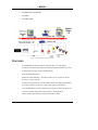
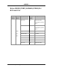
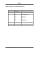
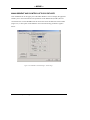
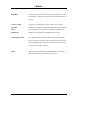
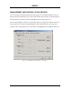
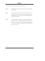
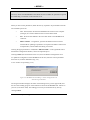
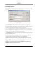
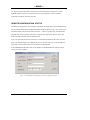
1
---MAVIX---
Med iaRacer® 100
Su rvei llance Multimedia
Gatew ay
--- USER MANUAL ----- PRE LIMINARY - --
MediaRacer® 100 [MT0002 - Rev 1.10]
---MAVIX---
TABLE OF CONTENTS
TABLE OF CONTENTS................................................................ ................ 2
MEDIARACER ® 100 OVERVIEW .................................................................4
INTEGRATED SURVEILLANCE SYSTEMS .............................................................. 4
CHAPTER 1 ................................ ................................................................ 5
MEDIARACER ® 100: SYSTEM DESCRIP TION .............................................. 5
SYSTEM DESCRIPTION ................................................................................... 5
CONFIGURATION – DESCRIPTION OF SYSTEM COMPONENTS..................................... 6
FEATURES................................................................ ..................................7
CHAPTER 2 ................................ ................................................................ 9
MEDIARACER ® 100: END UNITS.................................................................9
GENERAL DESCRIPTION ................................................................................. 9
MEDIA RACER® 100 – F RONT PANEL DESCRIPTION ............................................. 10
Video Channel............................................................................................................. 10
Serial Data Channel ................................................................................................... 11
CONSOLE LED .......................................................................................................... 11
Serial TRUNK Channel - Network Connector (RJ-45).............................................. 11
TX LED ....................................................................................................................... 11
rX LED ........................................................................................................................ 11
Network Port............................................................................................................... 11
System Indicators ........................................................................................................ 12
MEDIA RACER® 100 – REAR PANEL DESCRIPTION ................................ .............. 13
POWER - DC CONNECTOR ................................ ............................................ 14
DIO (Discrete Input/Output) Channels ...................................................................... 14
CHAPTER 3 ................................ .............................................................. 15
MEDIARACER ® 100: SPECIFICATION AND FEATURES ............................. 15
MEDIA RACER® 100 T ECHNICAL SPECIFICATION ................................................ 15
CONNECTORS MAPPING TABLE................................ ...................................... 19
10/100 RJ-45 Connector............................................................................................. 19
SERIAL RS232 (COM 1) & RS485 (COM 2) RJ-45 CONNECTOR ............................ 20
Serial trunk RJ-45 Connector (COM 3)...................................................................... 21
DI (DISCRETE Input) Block Terminal....................................................................... 22
Do (DISCRETE output) Block Terminal..................................................................... 22
CHAPTER 4 ................................ .............................................................. 23
MEDIARACER ® 100: INSTALLATION AND CONFIGURATION ................... 23
INSTALLATION REQUIREMENTS................................ ...................................... 23
POWER CONNECTION ................................ .................................................. 24
CONNECTION TO NETWORK .......................................................................... 25
CONNECTING DEVICES ................................................................................ 25
MediaRacer® 100 [Preliminar y]
2
---MAVIX--Connecting Video Sources .......................................................................................... 25
Connecting the Monitor.............................................................................................. 26
Connecting Audio Devices.......................................................................................... 26
Connecting Devices to RS232 and RS232/485 Ports.................................................. 27
Connecting Discrete Input/Output (DIO) Devices ..................................................... 27
CONFIGURATION SETTINGS........................................................................... 28
Console Setting........................................................................................................... 28
MediaRacer® 100 Unit Setting................................................................................... 29
System Settings............................................................................................................ 31
Network Settings......................................................................................................... 34
Software Update settings ............................................................................................ 36
Built-In Tests ............................................................................................................... 38
Loading of Configuration Default Values................................................................... 38
Reboot......................................................................................................................... 38
Application Log Screen............................................................................................... 39
ADVANCED CONFIGURATION ................................................................ ........ 40
INSTRUCTIONS FOR QUICK SETUP ................................................................... 40
CHAPTER 5 ................................ .............................................................. 42
MEDIARACER ® 100: OPERATION............................................................. 42
MEDIA RACER® LINK MANAGER.................................................................... 42
Installation of MediaRacer® Link Manager .............................................................. 43
Activating MediaRacer® Link Manager..................................................................... 43
Communications Management Between MediaRacer® 1000 units ........................... 45
Management and Control of Video Devices ............................................................... 47
Management and Control of Audio Devices............................................................... 51
Management and Control of RS232 Devices .............................................................. 53
Management and Control of DIO Devices ................................................................. 55
MEDIA RACER® LINK MANAGER - REMOTE CONFIGURATION TOOL......................... 57
Definition of Advanced Configuration Settings.......................................................... 59
Software Updat e.......................................................................................................... 62
Remote Configuration Status...................................................................................... 63
Resetting & Controlling the Operation Mode ............................................................ 64
MAVIEW M ANAGEMENT SOFTWARE ............................................ 66
The MAVIEW API....................................................................................................... 67
MAVIEW Player Software .......................................................................................... 68
CHAPTER 6 ................................ .............................................................. 69
MEDIARACER ® 100: TROUBLESHOOTING ............................................... 69
NETWORK T ROUBLESHOOTING................................ ...................................... 69
RS232/485 TROUBLESHOOTING..................................................................... 70
THE RED LED IS CONSTANTLY LIT................................................................. 71
VIDEO T ROUBLESHOOTING........................................................................... 72
AUDIO T ROUBLESHOOTING........................................................................... 73
MediaRacer® 100 [Preliminar y]
3
---MAVIX---
MED IARAC ER® 100
OVERVIEW
INTEGRATED SURVEILLANCE S YSTEMS
MediaRacer® 100 is a remote intelligent monitoring and surveillance building block for
use in implementing broad surveillance solutions, including transportation, industrial
process control and security applications. MediaRacer® 100 utilizes advanced computer
networking technology to integrate information from multimedia devices (audio, visual
and digital data) in order to provide the user with a reliable, flexible and interactive
monitoring system.
The MediaRacer 100 introduces enhanced capabilities embedded in the product design
considerring the needs of today and the future market.
MediaRacer® 100 enables digital transmission, switching and control of remote
multimedia surveillance devices spread over large areas. Compressed audio and video
information and other digital data are captured by remote sensors and transmitted to the
MediaRacer® 100 unit, where they are processed. The data is then packaged by the
TCP/IP protocol and transmitted over a standard high-speed computer communications
network to the control center.
The challenge facing any monitoring and surveillance system design today is to build a
concept for tomorrow. Systems installed today are often outdated by the time their
implementation has been completed. The key objective is to build an open system that is
never closed to future options and which facilitat es expansion of capacity and
functionality in an efficient and flexible manner. MediaRacer® 100 provides the solution.
MediaRacer® 100 is designed and manufactured by MAVIX. Based on an open system
architecture, the MAVIX Solution brings together the considerable progress made to date
with information networking technology and the sophisticated requirements of current
monitoring systems. The MAVIX System integrates, manages and controls all components
of the monitoring system, including cameras, audio devices, monitors, alarms, sensors, and
controllers.
MediaRacer® 100 [Preliminar y]
4
---MAVIX---
CHAPTER 1
MED IARAC ER® 100:
SYSTEM D ESCR IPTIO N
SYSTEM DESCRIPTION
MediaRacer® is a new family of MAVIX Multimedia Gateways, designed to provide high
quality delivery of video, audio and other electronic data using TCP/IP networks.
The flagship member of the family, MediaRacer® 100, features full motion video at
different resolutions (PAL/NTSC), suporting state of the art compression standards, and is
based on low cost, compact design, while maintaining the high -end system qualities that
are found in MAVIX products. MediaRacer® 100 also features unique capabilities for
low-end applications, such as non-managed point-to-point automatic link recognition and
setup, eliminating the need for costly management applications. This allows end users to
tailor the solution to their exact needs and budget.
MediaRacer® 100 offers up to 1 video camera attachment (in the future it will offer two
attachments), a bi-directional audio port, RS232, RS485 and Digital I/O connections, all
using a box the size of a VHS cassette. It facilitates connection of access control devices,
intercoms, Public Address Systems, PTZ (Pan, Tilt, Zoom) for video cameras and so forth.
The product is also planned to feature after future development an IDE connection to an
optional hard disk, allowing users to locally record events. This highly integrated solution
performs as a zone concentrator for numerous video, audio and data devices, eliminating
the need for multiple hardware platforms for different protocols, and thus significantly
reducing the overall cost of the installation.
The MediaRacer platform is generic, meaning that in addition to the MPEG-4 compression
standard supported today, it will be capable of supporting in the future new compression
standards, just by downloading a new s/w version. The product can also perform as a
compressor or a decompressing unit, saving cost in logistics of customers and end users.
MediaRacer® 100 [Preliminar y]
5
---MAVIX--Small point-to-point applications are easily monitored and controlled by the MediaRacer®
Link Management application, provided with all units. For medium to large applications,
MediaRacer® 100 is fully managed by the MAVIX MAVIEW Management System,
enabling unified monitoring and control of large installations from a single management
console.
MAVIEW software enables video bandwidth and quality to be controlled and adjusted to
fit specific application requirements. Moreover, monitoring a video picture on the
MAVIEW desktop screen is another unique option available that uses the MAVIEW
Player feature.
MediaRacer® 100 is a wide -range solution that can be used by low, medium and largesized applications. It supports different video stream bandwidths according to the various
compression types. This capability is achieved by the use of the new, state-of-the-art
MPEG-4 compression standard.
MediaRacer® 100 also allows significant bandwidth savings by optimizing the UDP and
IP packets. It also supports IP Multicast. End users can determine the video quality and
bandwidth budget, simply by defining a configuration parameter during the setting up of
the unit. As bandwidth becomes more available, the end user can improve the video
parameters by means of a simple update of the unit’s configuration parameters. In this way
the MediaRacer® 100 based solution “grows” with the customer budget, greatly reducing
the total life cost of installation.
CONFIGURATION – DESCRIPTION OF S YSTEM
COMPONENTS
MediaRacer® 100, the MAVIX solution to remote intelligent surveillance, is based on
open system architecture. The basic configuration, as seen in Figure 1, contains the
following components:
?
End units – total two: One MediaRacer® 100 working as a Camera Side
unit (compression unit), located on the remote side and the other, a
MediaRacer® 100 working as a Monitor Side (decompression unit), located
on the monitor side, usually in the control room.
?
Software components:
MediaRacer® 100 [Preliminar y]
6
---MAVIX--√
MediaRacer® Link Manager
√
MAVIEW
√
MAVIEW SDK
Figure 1: Basic Managed Configuration
FEATURES
?
The MediaRacer® System supports MAVIX M x N Virtual Matrix
architecture, which enables logical switching of M distributed sources and
N destinations of video, audio and data over IP.
?
Remote bandwidth control.
?
Multicast Video capability – the same camera can be viewed on several
monitors, over the network.
?
Advanced compression of video and audio executed by dedicated hardware
providing real time, full motion – high video quality (PAL/NTSC).
?
On-line adjustment of video compression parameters enables the fitting of
specific resolution and motion requirements to the application.
?
Video monitoring on desktop, using the MAVIEW -Player.
MediaRacer® 100 [Preliminar y]
7
---MAVIX--?
Direct attachment integrating multiple video, audio and data monitoring
devices.
?
Bi-directional audio connections for intercom or other audio monitoring
features.
?
Audio Broadcast for public address systems.
?
Support for up to two RS-232, and one RS-485 interfaces.
?
Support for up to four Opto-isolated Discrete Inputs/Outputs.
?
Automatic link setup without the need for a management system (Point to
Point).
?
Pre/Post Alarm recording (ready).
?
Transparent Serial Channel between Camera and Monitor sides enabling
easy integration with 3rd party devices.
?
Low cost latency supporting of a critical mission application, requiring
precise PTZ control.
MediaRacer® 100 [Preliminar y]
8
---MAVIX---
CHAPTER 2
MED IARAC ER® 100:
END UN ITS
GENERAL DESCRIPTION
MediaRacer® 100 enables conversion of analog data from its original form, to a digital
packet on one side of a network, back to its original analog form on the other side.
MediaRacer® 100 handles input composite video signals, an output video signal, audio
signals for intercom, serial output data for the camera pan, tilt, zoom, washer, wiper and
heater control, and other discrete input/output data.
MediaRacer® 100 provides the physical connection to the network and remote site
surveillance devices. The information is packaged using the UDP/IP protocol and routed
to the Control Center via the standard data communications network.
MediaRacer® 100 can be attached directly to high-speed standard data communications
networks, using the Ethernet or Fast Ethernet connections (10/100Base-TX), and
optionally to low-speed data networks such as the telephone network (utilizing an optional
built-in modem) ISDN, serial links (supporting AT command), etc, via appropriate
external modems.
MediaRacer® 100 is based in a Codec architecture design.
MediaRacer® 100 Camera side unit is usually located at a remote site, serving as a zone
concentrator for the various devices required for the monitoring and control. The unit
enables communication sessions between remote surveillance devices and control room,
and between remote surveillance devices attached to different units. Each medium (video,
audio, sensors) maintains a separate independent session. In this way the video from unit
A may be delivered to unit B, and concurrently the audio of unit A may be delivered to
unit C. The MediaRacer® 100 monitor side unit is usually located in the control room and
MediaRacer® 100 [Preliminar y]
9
---MAVIX--enables the viewing of the video pictures taken by the remote cameras on analog monitors.
MEDIA RACER® 100 – FRONT P ANEL DESCRIPTION
The front panel of the MediaRacer® 100 contains:
?
Video Channel (Video In or Video Out)
?
Serial Data Channel
?
Serial Trunk Chnnel
?
Network Port
?
System Indicators
VIDEO CHANNEL
VIDEO IN - MediaRacer® 100 Camera Side unit
The VIDEO IN channel consists of one composite video input that facilitate the
attachment from video source - camera or analog video matrix - to the Media Racer 100
Camera Side unit.
The video input connector has it’s own LED. The LED, which is lit, indicates the video
source selected by the user.
VIDEO OUT - MediaRacer® 100 Monitor Side unit
The VIDEO OUT channel has a single connector. An analog monitor can be connected to
this connector, enabling viewing of video pictures taken by the remote cameras.
MediaRacer® 100 [Preliminar y]
10
---MAVIX---
SERIAL DATA CHANNEL
Devices that transfer data, such as PTZ control for video camera, computers, VMS
(Variable Message Sign) boards and other industrial control systems, can be connected to
RS232 (COM 1) and RS485 (COM 2) ports.
The unit supports RS485 Half and Full Duplex communication, selecteble by jumpers.
CONSOLE LED
Console LED located next to Serial Data Connector (RJ -45) indicates, that RS232
(COM1) port is chosen to be a Console Port.
SERIAL TRUNK CHANNEL - NETWORK CONNECTOR (RJ-45)
Serial Trunk Channel is a modular option for communication. This is in addition to the
primary 10/100Base-TX data trunk channel on -board. The Serial Trunk channel can be
used for standard RS232 communication with all external modem control signals and with
AT command support, built-in V-90 PSTN modem and built-in ISDN modem.
TX LED
The TX LED indicates Transmit activities over the serial trunk network.
RX LED
The RX LED indicates Receive activities over the serial trunk network.
NETWORK PORT
10/100Base-TX - Network Connector
Enables a MediaRacer® 100 unit to be connected to an Ethernet/Fast Ethernet standard
data communication network, complying with the IEEE 802.3U standard.
MediaRacer® 100 [Preliminar y]
11
---MAVIX---
LNK LED
The LNK LED lights when a communication link signal is received in the MediaRacer®
100 unit. The lit LED indicates that a connection to the network has been established.
ACT LED
The ACT LED indicates data activity over the network.
SYSTEM INDICATORS
ON – Power LED
The ON LED lights when the system is connected to a power supply and is switched on.
The ON LED will blink every 5 seconds, which indicates proper system operation.
FLT LED
When the FLT LED is lit or blinking, it indicates one of the following problems:
?
The MediaRacer® 100 unit failed during the self-test.
?
The system failed to initialize the operation software in Application mode.
?
The MediaRacer® 100 unit began the reset cycle.
MediaRacer® 100 [Preliminar y]
12
---MAVIX---
MEDIA RACER® 100 – REAR P ANEL DESCRIPTION
The rear panel of the MediaRacer® 100 contains:
?
Audio Channel
?
Power Connector
?
DIO (Discrete Input/Output) Channel
AUDIO CHANNEL
The audio channel is designed for stereo capabilites and is used to connect an intercom
(bi-directional channel) or a microphone and speaker connection (two uni-directional
channels) or a public address system (uni-directional channel from one point to multiple
points). The AUDIO OUT connectors are used to connect a speaker to the unit and the
AUDIO IN connector is used to connect a microphone to the unit.
Installation of a public address system in the audio channel requires the attachment of a
microphone on the MediaRacer® 100 Monitor Side unit (control side) and speakers on the
MediaRacer® 100 Camera Side unit on the remote side.
MediaRacer® 100 [Preliminar y]
13
---MAVIX---
POWER - DC CONNECTOR
The POWER DC connector is used to connect the cable of the desktop power supply 5V
to the MediaRacer® 100 unit.
DIO (DISCRETE INPUT/OUTPUT) CHANNELS
DIO devices, such as sensors (temperature, light etc.), automatic gate opening controls and
alarms can be connected to a Discrete Input/Output (DIO) block terminal. The DIO block
terminal has two dry-contact input and two opto-isolated output ports.
The positive terminal of the DO should be connected to one end of the relay coil, while the
second end is connected directly to the external power supply positive output.
The negative terminal of the DO should be connected to the external power supply GND
output.
The ON/OFF switch can be directly connected between (+) and (–) terminals of the
Discrete Inputs.
MediaRacer® 100 [Preliminar y]
14
---MAVIX---
CHAPTER 3
MED IARAC ER® 100:
SPEC IFICAT ION AND FEATURES
MEDIA RACER® 100 T ECHNICAL S PECIFICATION
Video Interface
Coding Algorithm
MPEG-4 Up to 6Mbps
Formats
PAL or NTSC
Resolution
4SIF, SIF, QSIF *
Frame Rate
Up to full frame rate*
Input
Form
Composite
Impedance
75Ω
Level
TV Standard
Form
Composite
Impedance
75Ω
Level
TV Standard
Output
Connector
BNC
Cable Length
Max. 30 m., without degradation of
color and video parameters
* Dynamic selection using MAVIEW or MediaRacer® Link Manager.
MediaRacer® 100 [Preliminar y]
15
---MAVIX--Network Interface
IEEE 802.3/802.3U
10/100Base-TX (with Auto-Negotiation)
RJ-45
Cable Type
CAT5 UTP
Cable Length
Max. 100 m.
Audio Interface
Coding Algorithm
G.711, G.729A
Bit Rate
64kbps / 8kbps
Inputs
RCA headphone jack
Voltage:
160mV RMS MAX
Input Gain:
Software adjustable in:
1dB steps from -30dB to +30dB
Impedance:
10kOhm, AC coupled
S/N ratio:
> 90dB @ full scale
Output
RCA headphone jack
Full scale voltage output:
1V RMS
Output Gain:
Software adjustable in:
1dB steps from -30dB to +30dB
Minimum Load:
16O
S/N Ratio:
>90Db @ for full scale output
MediaRacer® 100 [Preliminar y]
16
---MAVIX---
Serial Interface
RS-232 & RS-485 (COM1 & COM2)
RJ-45
Serial Trunk Interface (optional)
RS-232 (COM 3 Full Control),
RJ-45
Discrete Interface Inputs
Opto-Isolated
2 Dry Contact Ports
Discrete Interface Outputs
Opto-Isolated
Outputs: Voltage
Max 24VDC
Current
Max 90 mA
Physical Dimensions
Size (WxHxD)
19.5x2.8x14 cm (7.67”x1.1”x5.51”)
Weight
0.5 kgs
Power Supply Mains Connection
Voltage Full Auto Range (+/- 10%)
100-240 VAC
Frequency
47 - 63Hz
Power Consumption
9W Typical (4SIF) 7W Typical (SIF)
Environmental Conditions
Operating Temperature (Indoor)
+0° to 50°C (41° to 122°F)
Operating Temperature (Outdoor)
-15° to 65°C (5° to 149°F)
Storage Temperature
-20° to 70°C (-4° to 158°F)
Operating Humidity
5% to 95% (Non-Condensing)
MediaRacer® 100 [Preliminar y]
17
---MAVIX---
Certifications
Safety
UL Listed
CE MARK
Electromagnetic Interference (EMC)
FCC 47 CFR part 15 subpart B, Class A
CE, Class A
MediaRacer® 100 [Preliminar y]
18
---MAVIX---
CONNECTORS MAPPING T ABLE
10/100 RJ-45 CONNECTOR
Pin Number
Signal Name
1
TD+
2
TD-
3
RD+
4
Not Used
5
Not Used
6
RD-
7
Not Used
8
Not Used
Figure 3 -1: RJ-45 Connectors – Pins Order
MediaRacer® 100 [Preliminar y]
19
---MAVIX---
S ERIAL RS232 (COM 1) & RS485 (COM 2) RJ45 CONNECTOR
Pin
RS232
Number
Signal
1
Description
RS485
Description
Signal
Not Used
RX+
Differential Data
(Half Duplex optional,
TRX+)
2
Not Used
RX-
Differential Data
(Half Duplex optional,
TRX-)
3
GND
Signal Ground
GND
Signal Ground
4
TxD
Transmit Data
Not Used
5
RxD
Receive Data
Not Used
6
Not Used
GND
Signal Ground
7
Not Used
TX+
Differential Data
8
Not Used
TX-
Differential Data
MediaRacer® 100 [Preliminar y]
20
---MAVIX---
SERIAL TRUNK RJ -45 CONNECTOR (COM 3)
Pin Number
Signal Name (for
Description
RS232 only)
1
RTS
Request to Send
2
DTR
Data Terminal Ready
3
GND
Signal Ground
4
TxD
Transmit Data
5
RxD
Receive Data
6
DCD
Data Carrier Detect
7
DSR
Data Set Ready
8
CTS
Clear to Send
MediaRacer® 100 [Preliminar y]
21
---MAVIX---
DI (DISCRETE INPUT) BLOCK TERMINAL
Pin Number
Signal Name
1
IN 1+
2
IN 1-
3
IN 2+
4
IN 2-
DO (DISCRETE OUTPUT) BLOCK TERMINAL
Pin Number
Signal Name
1
OUT 1+
2
OUT 1-
3
OUT 2+
4
OUT 2-
MediaRacer® 100 [Preliminar y]
22
---MAVIX---
CHAPTER 4
MED IARAC ER® 100:
I NSTALLATION AN D CON FIGU RAT ION
INSTALLATION REQUIREMENTS
MediaRacer® 100 units may be installed indoors or outdoors, in a dry and clean
environment. The location should allow easy access to the cable channels or ducts. Do not
install MediaRacer® 100 where it may be subjected to extreme vibrations, dust or fumes,
which may damage the unit.
Note: Pay attention to operating environment requirements as defined in the Specifications
section.
Check that the unit supplied includes the following:
?
MediaRacer® 100 unit
?
Desktop Power Supply
?
RS 232 Configuration Cable for COM 1 port (at least one cable per
package)
?
CD containing MediaRacer® 100 User Manual & MediaRacer® Link
Manager Application.
?
Mating terminal block for DIO attachment.
When installing the MediaRacer® 100 unit, leave enough space at the front and back of
the unit to allow free air circulation. Clearance of at least 1 ft. (approx. 33 cm) should be
provided behind the unit to allow for easy access of cables.
MediaRacer® 100 [Preliminar y]
23
---MAVIX---
POWER CONNECTION
Connect one end of the desktop power supply (supplied with the unit) to the MediaRacer®
100 unit, using the POWER connector. Connect the other cable to an AC power source.
Verify that the ON LED (located on the front panel) is lit and that after several seconds the
FLT LED goes out.
IMPORTANT:
Always connect the desktop power supply to the unit before you connect it to the mains
power supply. Failure to do this can cause irreversible damage to the Media Racer 100.
Special care must be taken to connect the cables in the proper sequence. First, connect the
desktop power supply DC cable to the MediaRacer® 100 unit, using the POWER DC
connector, then connect the other power supply cable to an AC power source.
MediaRacer® 100 [Preliminar y]
24
---MAVIX---
CONNECTION TO NETWORK
Connect one end of a communication cable (CAT5 direct cable) to the 10/100 connector
on the front panel of the MediaRacer® 100 unit. Connect the other end of the
communication cable to your local Ethernet network (SWITCH/HUB). Verify that the
LNK LED is lit.
CONNECTING DEVICES
CONNECTING VIDEO SOURCES
1.
One video source may be attached to the MediaRacer® 100.
In order to attach a video source, connect one end of a video
coax 75 Ω cable to the video output of the Camera. Connect
the other end of the cable to one of the VIDEO IN
????? ???? Comment
???? " ? " ???? " ?????
socket ??? connector
"??? ???? ?????? ?? ???' ?
???? ?????? " ? ???' ?? ???
connector?????? ??? ????
connector????" ? ?????????
" socket" ? ?
connector, located on the unit front panel. The lit LED
indicates the camera that has been selected from the attached
cameras.
Note: Pay attention to maximum coax cable length as
defined in the Specifications section.
MediaRacer® 100 [Preliminar y]
25
---MAVIX---
CONNECTING THE MONITOR
1.
The monitor connection is usually made in the control room,
enabling the viewing of video pictures taken by the remote
camera. In order to attach an analog monitor to the
MediaRacer® 100 CM model, connect one end of a video
coax 75Ω cable to the video inputs of the monitor and the
other end to the VIDEO OUT connector located on front
panel of the unit.
CONNECTING AUDIO DEVICES
2.
Connect a microphone to the AUDIO IN connector (located
on the rear panel of the unit).
3.
Connect a speaker to the AUDIO OUT connector (located
on the rear panel of the unit).
Note: An intercom system may be used in place of a
microphone and speaker.
MediaRacer® 100 [Preliminar y]
26
---MAVIX---
CONNECTING DEVICES T O RS232 AND RS232/485 PORTS
Devices that transfer data, such as computers, VMS boards, camera control and other
industrial control systems can be connected to the COM ports.
1.
Connect the data device to the MediaRacer® 100 unit via
the COM ports, according to the connectors mapping table.
CONNECTING DISCRETE INPUT/OUTPUT (DIO) DEVICES
DIO devices, such as sensors (temperature, light etc.), automatic gate opening controls and
alarms can be connected to a Discrete Input/Output (DIO) connector. The DIO connector
has four opto-isolated input and four opto-isolated output ports.
1.
Connect the DIO device to the MediaRacer® 100 unit via
the DIO connector, as specified in the Specification section
and according to the connector mapping table.
MediaRacer® 100 [Preliminar y]
27
---MAVIX---
CONFIGURATION S ETTINGS
After the various devices have been attached to the MediaRacer® 100 unit, it is necessary
to define all the initialization and setup values required for the basic operation of the
MediaRacer® 100 unit. The parameters to be defined include details of the MediaRacer®
100 unit and some network parameters. The default manufacturer settings can be changed
in order to configure the MediaRacer® 100 unit according to the site requirements.
CONSOLE SETTING
The definition of the various setup values is performed by connecting a computer with a
built-in Hyper Terminal application to the MediaRacer® 100 unit. Power on the computer
and define the Hyper Terminal application COM port setting values as follows (see Fig 41):
?
Bits per second – 38400
?
Data bit – None
?
Stop bits – 1
?
Flow control – None
Figure 4-1: Hyper Termin al Application COM Port setting Values
MediaRacer® 100 [Preliminar y]
28
---MAVIX--The Hyper Terminal application COM port setting should be identical to the setting for the
MediaRacer® 100 unit COM 1.
MEDIARACER® 100 UNIT SETTING
Connect the computer to the MediaRacer® 100 unit via the unit COM 1 (RS232 port),
using the cable supplied with the unit. Disconnect any device attached to the unit via this
port. Remember to reconnect the required device after you have completed the settings of
the MediaRacer® 100 unit.
When the computer has been connected to the MediaRacer® 100 unit and the Hyper
Terminal application is active, reboot the MediaRacer® 100 unit (disconnect the power
cable from the power source and then reconnect it).
During the reboot process, press the space bar to display the “MediaRacer® Service
Software” main menu (Fig 4-2).
Figure 4-2: MediaRacer® Service Software – Main Menu
MediaRacer® 100 [Preliminar y]
29
---MAVIX--To select a menu option use the arrow keys, or [CTRL]+[N] to scroll downwards, and
[CTRL]+[U] for scrolling upwards. Menu items may also be selected by typing the item
number when the cursor is flashing next to the prompt: Choice >. To return to the main
menu from any sub-menu press the [Ctrl] and the [P] keys simultaneously.
Press [Ctrl] + [D] simultaneously to get an explanation about a selected line or field at the
bottom of the screen.
Fields marked with an asterisk and in parentheses denote toggle options that are operated
by the space bar
Fields shown in parentheses are edit options.
Press [ENTER], to save the values in the current menu.
Options 1 and 2 in the main menu enable the user to configure the unit – i.e. definition of
setting values.
Notice:
All setting values that have been changed during the configuration process will be valid
only after rebooting of the MediaRacer® 100 unit.
MediaRacer® 100 [Preliminar y]
30
---MAVIX---
SYSTEM SETTINGS
Select option 1 from the main menu to display the system setting menu (Fig 4-3).
Figure 4 -3: MediaRacer® Service Software – System Settings
This menu displays the following system identification parameters: MediaRacer® 100 unit
Mac Address and Serial Number, Service Software Creation Date and BSP (Boot Software
Package) Creation Date.
MediaRacer® 100 [Preliminar y]
31
---MAVIX--The definitions of the values of the remaining fields may be changed. These are follows:
Console I/O
Defines the status of COM 1.
Enable value (default value) means that access to all
MediaRacer® Service Software options and Application
Log Screen are enabled and visible. Selection of the
Enable value will not permit the connection of any other
devices to the COM 1 port to be active. Change the
value of this filed to Disable if you intend to connect
other devices to COM 1.
Note: When the Disable option is selected while the unit
is booting, press the spacebar to automatically enable
“Console I/O” to display MediaRacer® Service
Software main menu”.
Default Baud
Defines the baud rate of the COM 1 unit (for console
connection only). This value should be identical to the
Bits per second value defined in the Hyper Terminal
application port setting window.
BIST
When this option is enabled (disabled by default), it
starts the self test of the MediaRacer® 1000 unit during
start-up. Self test will not be performed by the
MediaRacer® 100 unit when the Disable value is
selected.
Boot timeout (sec)
Defines the timeout interval (in seconds) during which
pressing the space bar displays the MediaRacer®
Service Software main menu. The manufacturer default
value is 3 seconds.
MediaRacer® 100 [Preliminar y]
32
---MAVIX---
Boot mode
Defines the different operation modes of the
MediaRacer® 100 unit.
Application – normal operation mode for the
MediaRacer® 100 unit.
Update Flash – an operation mode for performing
automatic application software updates.
Maintenance – an operation mode that enables
performance of maintenance tasks only, associated with
the MediaRacer® Service Software. This mode of
operation cancels the requirement to press the space bar
during the rebooting process, and forces the unit to start
up directly into the MediaRacer® Services Software
main menu. This mode should only be used by qualified
technicians.
MediaRacer® 100 [Preliminar y]
33
---MAVIX---
NETWORK SETTINGS
Selection of option 2 from the MediaRacer® Service Software main menu causes the
networking setting menu to be displayed (Fig 4-4).
Figure 4-4: MediaRacer® Service Software – Network Settings
MediaRacer® 100 [Preliminar y]
34
---MAVIX--This menu is used to define the network parameters of the MediaRacer® 100 unit.
The field definitions are as follows:
IP node address
Defines the IP address of the MediaRacer® 100 unit,
according to the local network requirements.
Network subnet mask
Defines the IP Network subnet mask, according to
the local network requirements.
Gateway IP node address
Defines the Gateway IP node address, according to
the local network requirements.
DNS Server IP node address
Value of the DNS Server IP node address (optional)
should not be equal to o.o.o.o
MediaRacer® 100 [Preliminar y]
35
---MAVIX---
SOFTWARE UPDATE SETTINGS
Selection of option 3 from the MediaRacer® Service Software main menu displays the
software Update Settings menu (Fig 4-5).
Figure 4-5: MediaRacer® Service Software – Software Update Settings
This menu is used to define the required parameters for establishing a connection to a FTP
server. For more information on the Software application, refer to section: "MediaRacer®
Link Manager - Remote Cobfiguration Tool" in Chapter 5.
MediaRacer® 100 [Preliminar y]
36
---MAVIX--The field definitions are as follows:
IP node address
The address of the FTP server, to be
connected to the MediaRacer® 100 unit
when software updating is required.
File name
The file name, used for updating software.
Change the default if necessary.
User name
User name - parameter required when
connecting the MediaRacer® 100 unit to an
FTP server.
Password
A parameter required for connecting the
MediaRacer® 100 unit to an FTP server,
and for Maintenance Mode login.
MediaRacer® 100 [Preliminar y]
37
---MAVIX---
BUILT-IN TESTS
Selection of option 4 from the MediaRacer® Service Software will display the results of
the last running of the Built-in Tests in the MediaRacer® 100 unit (Fig 4-6).
Figure 4 -6: MediaRacer® Service Software – Built-In Tests
LOADING OF CONFIGURATION DEFAULT VALUES
Selection of Option 5 from the MediaRacer® Service Software will cancel all the changes
made to the parameters, and restore the manufacturer default values.
REBOOT
Selection of Option 6 from the MediaRacer® Service Software will cause the reboot of the
MediaRacer® 100 unit.
MediaRacer® 100 [Preliminar y]
38
---MAVIX---
APPLICATION LOG SCREEN
If the Console I/O value is set to Enable when the reboot option for to the MediaRacer®
100 unit is selected, initialization messages are displayed on the screen showing the status
of the procedure (Fig 4-7).
Figure 4 -7: MediaRacer® Service Software – Application Menu
On completion of the initia lization process, the prompt Station > is displayed, indicating
that the MediaRacer® 100 unit is ready for operation. Verify that the FLT LED is not lit.
If Console I/O value is set to disable, and you choose to reboot the MediaRacer® 100 unit,
while the computer is still connected, messages will not be displayed on the screen. The
MediaRacer® will be ready for operation only when the FLT LED is not lit.
MediaRacer® 100 [Preliminar y]
39
---MAVIX---
ADVANCED CONFIGURATION
Definition of advanced configuration settings can be carried out using the Remote
Configuration Tool, which is an integral part of the MedaiRacer Link Manager Software.
The Remote Configuration Tool enables loading and editing of the unit’s configuration
file
The advanced configuration file, TASKMAN.ini, is part of the MediaRacer® 100
application software. The file contains all the initialization and setup values required for
the MediaRacer® 100 unit operation. The manufacturer default settings in the file can be
changed in order to configure the MediaRacer® 100 unit according to the site
requirements. The file is in ASCII format and can be modified using any text editor.
The parameters defined in this file include the MediaRacer® 100 unit details (OSD - On
Screen Display, address, etc.), devices connected to the unit inputs (camera or monitor,
etc.), description of the devices, video format and some network parameters.
For more detailed information about operating the Remote Configuration Tool, refer to
Chapter 5 - MediaRacer® 100: Operation.
INSTRUCTIONS FOR QUICK SETUP
1.
Connect a computer with a built -in Hyper Terminal
application to the MediaRacer® 100 unit COM 1 port (RS
232 port). Use the cable supplied with the unit. Disconnect
any device that is attached to the unit via this port.
2.
Verify that the default values for Hyper Terminal Port
setting are as shown in
Fig 4-1.
3.
When the Hyper Terminal application is active, reboot the
MediaRacer® 100 unit (disconnect the power cable from the
power source and immediately reconnect it).
MediaRacer® 100 [Preliminar y]
40
---MAVIX--4.
During the rebooting process press the space bar to start the
service software. When the main menu of the MediaRacer®
Service Software (Fig 4-1) is displayed, the user can change
default values and configure the MediaRacer® 100 unit
according to his own specifications.
5.
Select option 2 from the MediaRacer® Serv ice Software
main menu. In the “IP node address” field define the
IP address of the MediaRacer® 100 unit according to the
local network requirements. Enter appropriate values in the
other two fields according to the local network requirements.
Return to the main Menu by pressing the [Ctrl] + [P] keys.
6.
Select option 1 from the MediaRacer® Service Software
main menu. Change the default value in the “Console
I/O” to Disable if you intend to connect other devices to
the MediaRacer® 100 unit COM 1 port instead of the
computer. Verify that the value in the Boot mode field is
set to Application. If necessary, change values in the other
fields according to your requirements. Return to the Main
Menu by pressing the [ctrl] + [P] keys.
7.
Select option 6 from the MediaRacer® Service Software
main menu to reboot the MediaRacer® 100 unit.
Important: All setting values that have been changed
during the configuration process will be valid only after the
rebooting of the MediaRacer® 100 unit.
8.
Disconnect the computer from the MediaRacer® 100 unit
COM 1. Connect any other device to this port, as necessary.
9.
Use the Management Software - MediaRacer® Link
Manager Softawre (MLM) or MAVIEW - in order to
operate devices that are connected to the MediaRacer® 100
units.
MediaRacer® 100 [Preliminar y]
41
---MAVIX---
CHAPTER 5
MED IARAC ER® 100:
OPERAT ION
Operation of the unit entails connecting and controlling the devices on the Camera side of
the MediaRacer® 100 unit, located on the remote side, with the device(s) connected to the
unit’s monitor side (more than one unit) located in the Control Center(s).
The association process (definition of relationships) between the devices can be done
using one of the following applications:
?
MediaRacer® Link Manager (partial management)
?
MAVIEW Management software (full management)
?
Customer application build on MAVIEW SDK (full management)
MEDIA RACER® LINK M ANAGER
The MediaRacer® Link Manager software package enables the user to control and manage
a point-to-point application. MediaRacer® Link Manager provides the operator with only
partial management for controlling and possessing devices connected to the MediaRacer®
100 Camera Side unit (located in the remote site), and devices connected to the
MediaRacer® 100 Monitor Side unit (located in control center).
MediaRacer® 100 [Preliminar y]
42
---MAVIX---
INSTALLATION OF MEDIARACER® LINK MANAGER
Installation of the MediaRacer® Link Manager software package in a personal computer is
the stage that precedes the activation of MediaRacer® Link Manager as a control and
possess management tool for devices connected to the MediaRacer® 100 units.
To install the MediaRacer® Link Manager software in your PC, insert the CD-ROM you
received with the MediaRacer® 100 unit, into your computer. Double-Click the
LINKMANAGER.exe icon, and follow the instructions on each screen of the installation
procedure.
When the initial stages have been completed, the MediaRacer® Link Manager can be
activated. The stage that follows the installation of the MediaRacer® Link Manager is the
connection of the computer to the communications network to which the MediaRacer®
100 Camera Side and MediaRacer® 100 Monitor Side units are connected.
ACTIVATING MEDIARACER® LINK MANAGER
When running the MediaRacer® Link Manager software for the first time the dialog box
in Figure 5.1 – MediaRacer® Link Manager – will be displayed.
Figure 5-1: MediaRacer® Link Manager - Opening Window Without IP Addresses
Enter the MediaRacer® Camera IP and MediaRacer® Monitor IP in the appropriate fields
(Figure 5-2). Check that the IP addresses of the MediaRacer® 100 units is according to the
local network requirements, as defined in the Network Settings (p. 44).
MediaRacer® 100 [Preliminar y]
43
---MAVIX---
Figure 5-2: MediaRacer® Link Manager - Opening Window With IP Addresses
After the IP addresses of the MediaRacer® 100 Camera Side and MediaRacer® 100
Monitor Side units have been defined in the opening dialog box of the MediaRacer® Link
Manager, the Main Window will appear (Figure 5-3).
The following options are available:
?
General – Communications management between MediaRacer® 100 units
?
Video – Control of video devices connected to MediaRacer® 100 units.
?
Audio – Control of audio devices connected to MediaRacer® 100 units.
?
RS232– Control of RS232 devices connected to MediaRacer® 100 units.
?
Discrete Inputs/Outputs – Control of DIO devices connected to
MediaRacer® 100 units.
MediaRacer® 100 [Preliminar y]
44
---MAVIX--Click one of the tabs at the top of the main window to enable selection of the activity
required – communications management or control of devices connected to the
MediaRacer® 100 units. The tab clicked will be brought to the front. The page in the
central area of the main window will change according to the option selected.
The lower right-hand corner of the main window contains two buttons that enable the
display of Help and to Exit the MediaRacer® Link Manager – irrespective of the button
that has been selected.
COMMUNICATIONS MANAGEMENT BETWEEN MEDIARA CER®
1000 UNITS
When the IP addresses of the MediaRacer® 100 units have been defined in the opening
dialog box of the MediaRacer® Link Manager, the main window will be displayed. The
General tab is brought to the front, and the General page is displayed. (Figure 5-3). This
page includes display fields and buttons that enable management of communications
between the MediaRacer® 100 units, as well as a reset option.
Figure 5-3: MediaRacer® Link Manager - General Page
MediaRacer® 100 [Preliminar y]
45
---MAVIX--IP Address
Read-only fields used to display the IP addresses of the
MediaRacer® 100 Camera Side unit and the MediaRacer®
100 Monitor Side unit.
Status Read-only field used to display data relating to the
communications status of the MediaRacer® 1000 units.
When the status is shown as Alive, there is communication
between the MediaRacer® 100 units and the MediaRacer®
Link Manager. All functions of the application can be
operated.
If the status is shown as No Response there is no
communication between the MediaRacer® 100 units and the
MediaRacer® Link Manager.
Communication status
The read-only field in the lower section of the General page
displays a message relating to the communications status
between the two units and the computer. The above example
shows the following: Tx:26 Rx:25 Qd:0. The message means
that Twenty-six commands have been transmitted (Tx) from
the computer to the two units. Twenty-five responses have
been received by the two units and the system is working
properly – with zero commands queued (Qd). This means that
the units are active and working.
Reset Clicking the Reset button in the MediaRacer® Camera
Section or in the MediaRacer® Monitor section of the
General page will reset the appropriate MediaRacer® 100
unit.
Clicking the Reset button will cause the MediaRacer® 100
unit to reboot only if the status is shown as Alive.
Disconnect All
Disconnect all communication links between the
MediaRacer® 100 units, so that there is no audio, video or
RS232 data transfer.
MediaRacer® 100 [Preliminar y]
46
---MAVIX---
MANAGEMENT AND CONTROL OF VIDEO DEVICES
Click the Video tab in the upper section of the Main Window to display the page that will
enable you to connect the monitor to the camera and control the parameters of the
connection specifications and the quality of picture transmission (Figure 5-4). A
description of the different control and monitoring parameters appears below:
Figure 5-4: MediaRacer® Link Manager - Video Page
MediaRacer® 100 [Preliminar y]
47
---MAVIX---
Camera selection
Set of four radio -buttons that enable the user
to select connection to one of the cameras
attached to the MediaRacer® 100 Camera
Side unit.
Brightness Contrast Saturation
A set of three sliders that enable adjustment
of brightness, contrast and saturation of the
picture. Adjustment of the required levels is
done by vertical dragging of the slider tag.
The value selected as the result of the
dragging of the tag is displayed in the box
above the slider.
Streaming Mode
Two radio-buttons that determine the way in
which video information is broadcast. The
selection in one of the radio -buttons is made
according to the application's requirements:
Fix bit rate or Fix quality.
Fix bit rate
This sets the number of bites of compressed
video pictures transmitted per second.
Horizontal dragging of the slider changes
the bit rate of the video transmission. The
selected value is displayed in the field to the
right of the
slider.
Fix quality
This sets the quality of the compressed
video pictures. Horizontal dragging of the
slider changes the quality of the picture. The
selected value is displayed in the field to the
right of the slider.
MediaRacer® 100 [Preliminar y]
48
---MAVIX---
Resolution
Slider that determines the resolution of the
picture transmitted. The default setting is
FULL. Reducing resolution is done by
dragging the slider tag horizontally
downwards. The selected value resulting
from the dragging of the tag is displayed in
the field to the right of the slider.
Possible values are as follows: FULL> SIF>
QSIF> QQSIF> QQQSIF>
NTSC PAL
Field(s) Per Second
FULL
720x480
720x576
SIF
352x240
352x288
QSIF
176x120
176x144
The maximum value for the number of
pictures transmitted per second is
determined by the method of transmission
used by the camera. (PAL or NTSC).
According the specifications of the camera
connected to the MediaRacer® 100 Camera
Side unit, click on the appropriate radiobutton. The Horizontal dragging of the
slider changes the number of pictures
(fields) per second that are transmitted by
the camera. The selected value is displayed
in the field to the right of the slider. Only in
Full position the transmitted video picture
consists of two fields per picture. A change
in the value of the Fields(s) per second
causes an automatic updating of Bit Rate
MediaRacer® 100 [Preliminar y]
49
---MAVIX--value (only if the Fix bit rate is selected).
PAL systems transmit a
maximum of 25 pictures per second whereas
NTSC systems transmit 30 pictures per
second.
On Screen Display
Field that enables the editing of text that will
appear in the upper left-hand corner of the
picture displayed on the monitor, the next
time connection is made.
Color
When this checkbox is highlighted – the
video image is displayed in color. Cancel
highlighting – the video image is transmitted
in gray tone.
Connect/Disconnect
Two buttons that enable connection/
disconnection of the video devices. Click
the Connect buttons to send video stream
from the camera to the monitor. Click the
Disconnect buttons to disable the transfer of
video stream between the MediaRacer® 100
units.
Status
This field displays the status of the
MediaRacer® 100 unit’s Video stream. The
display options are Connect or Disconnect.
MediaRacer® 100 [Preliminar y]
50
---MAVIX---
MANAGEMENT AND CONTROL OF AUDIO DEVICES
Click the Audio tab in the upper part of the Main Window screen to display the page that
enables you to control and monitor the parameters of the attributes of the audio devices
attached to the two MediaRacer® 100 units (Figure 5-5).
Figure 5-5: MediaRacer® Link Manager - Audio Page
MediaRacer® 100 [Preliminar y]
51
---MAVIX--A description of the different control and monitoring parameters appears below:
The page is divided into two sections. Each section controls one direction of the audio
stream.
Mic Volume
Slider that enables control of the microphone gain level.
Vertical dragging of the slider tag determines the required
microphone gain level. The selected value resulting from the
dragging of the tag is displayed in the field above the slider.
Volume
Slider that enables determination of the speaker audio volume.
Vertical dragging of the slider tag determines the speaker audio
volume. The selected value resulting from the dragging of the
tag is displayed in the field above the slider.
Connect/Disconnect
Two buttons enable Connection/Disconnection of the
microphone and speaker between the MediaRacer® 100
Camera Side unit and MediaRacer® 100 Monitor Side unit.
Click the Connect button to transfer audio stream between the
two MediaRacer® 100 units. Click the Disconnect button to
prevent the transfer of audio stream between the two
MediaRacer® 100 units.
Status
This field displays the status of the MediaRacer® 100 unit’s
Audio stream. The display options are Connect or Disconnect.
MediaRacer® 100 [Preliminar y]
52
---MAVIX---
MANAGEMENT AND CONTROL OF RS232 DEVICES
Click the RS232 tab in the upper part of the Main Window screen to display the page that
enables you to control and monitor the parameters of the RS232/485 (COM 2) devices
connected to the various MediaRacer® 100 units and control the data flow between them
(Figure 5-6). A description of the different control and monitoring parameters appears
below:
Figure 5-6: MediaRacer® Link Manager - RS232 Page
MediaRacer® 100 [Preliminar y]
53
---MAVIX---
Baud Rate
Drop-down window that determines the data baud-rate. When
the window is opened, select the desired value from the list of
options.
Number of Bits
Selection of a radio-button in each of these four sections
Stop Bits
enables the controlling of the RS485 parameters. Determining
Parity
the required value is according to the RS485 parameters of
Handshake
the device connected to the MediaRacer® 100 Unit.
Connect/Disconnect
Two buttons enable connection/disconnection of the RS232
devices. Click the Connect button to transfer signals between
the two MediaRacer® 100 units. Click the Disconnect button
to prevent the transfer of signals.
Status
This field displays the status of the MediaRacer® 100 units.
The display options are Connect or Disconnect
MediaRacer® 100 [Preliminar y]
54
---MAVIX---
MANAGEMENT AND CONTROL OF DIO DEVICES
Click on the Discrete Inputs/Outputs tab in the upper part of the Main Window screen to
display the page that enables you to control and monitor the parameters of the attributes of
the DIO devices connected to the two MediaRacer® 100 units (Figure 5-7).
The screen that appears contains two symmetrical parts: The upper part enables control of
the DIO devices connected to the MediaRacer® 100 Camera Side unit. The lower part
enables control of the DIO devices connected to the MediaRacer® 100 Monitor Side unit.
Figure 5-7: MediaRacer® Link Manager - DIO Page
MediaRacer® 100 [Preliminar y]
55
---MAVIX--A description of the different sections of this page appears below:
Outputs
Select the check box in the Outputs section to set/reset of appropriate
discrete output.
Inputs
Each display field (radio-button) shows an indication on the discrete
input status. The status of the entry port is only updated when the
Refresh button is pressed, or on a cyclical basis when the Automatic
refresh option is checked.
Alarms
Each display field (radio-button) shows an indication on the discrete
input event. An event is defined as a setting on of a specific input.
When there is an event, it is reported real-time by the MediaRacer®
100 unit to the MediaRacer® Link Manager and is displayed until the
Clear button is pressed.
MediaRacer® 100 [Preliminar y]
56
---MAVIX---
MEDIA RACER® LINK M ANAGER - REMOTE
CONFIGURATION T OOL
Definition of advanced configuration settings can be carried out using the Remote
Configuration Tool, which is an integral part of the MediaRacer® Link Manager Software.
The Remote Configuration Tool enables loading and editing of the unit’s configuration
file
Click the icon in the upper left-hand corner of theMediaRacer® Link Manager Main Menu
screen to open the scrolling window (Fig. 5-10).
Figure 5 -8: Operating the Remote Configuration Tool
Select About MediaRacer® Link Manager (Fig. 5-8) to display the version number of
the MediaRacer® Link Manager.
MediaRacer® 100 [Preliminar y]
57
---MAVIX--Select MediaRacer® Remote Configuration (Fig. 5-8) to activate the Remote
Configuration tool and display its main window from which the following activities can be
managed:
?
Updating of the configurations of MediaRacer® 100 units.
This activity uses the taskman.ini file.
?
Updating of the software installed in MediaRacer® 100 units.
This activity uses the ramcmpr.bin file.
?
Displaying information concerning the status of the MediaRacer® 100 unit.
This activity uses of the status.txt file.
?
Resetting the MediaRacer® 100 unit, and controlling the operation mode.
This activity uses the reset.txt file.
MediaRacer® 100 [Preliminar y]
58
---MAVIX---
DEFINITION OF ADVANCED CONFIGURATION SETTINGS
Updating a particular MediaRacer® 100 unit configuration is done by defining the
parameters in the taskman.ini file.
Run the Remote Configuration Tool in order to load the TASKMAN.ini file from the
MediaRacer® 100 unit to your PC.
When the Remote Configuration Main Window appears (Fig. 5-9), in the Local File
Name field, enter the name of the configuration file – taskman.ini, its directory path and
folder. Alternatively, click on the Browse button, located to the right of the field, to access
the folder and select the file from the displayed list.
Figure 5 -9: MediaRacer® Link Manager - Remote Configuration
Configuration Updating
According to the local file name, the Remote Field Name field displays the name of the
file as it appears or as it will be recorded in the specific MediaRacer® 100 or from a
specific MediaRacer® 100 Unit.
Type your username and password in the User and Password fields in the same way that
they were entered during the configuration process. If there is an error in the username or
password, it will not be possible to carry out the required update.
In the MediaRacer® IP field, enter the IP Address of the MediaRacer® 100 unit in which
you want to update the configuration.
MediaRacer® 100 [Preliminar y]
59
---MAVIX--Note:
The User, Password and MediaRacer® IP fields are used to define the parameters required
for establis hing a connection to the unit FTP server.
When you have set the parameters, define the activity required to be performed on the file.
The available options are:
?
Get – Read (load) a file from the MediaRacer® 100 unit to the computer
(manager) to a location defined in the Local File Name field.
?
Put – Write the file defined in the Local File Name to the MediaRacer®
1000 unit.
?
Edit Local File – Using Editor, open the file defined in the Local File
Name field for updating of parameters as required. The Editor is Microsoft
Notepad editor, which enables the editing of text files.
Clicking the appropriate button - Get, Put or Edit Local File - on the right-hand side of
the Remote Configuration Window, selects the required option.
Clicking Cancel (the fourth button in the row) closes the Remote Configuration Tool.
To update the configuration of the MediaRacer® 100 unit, after the various parameters
have been set, click the Get button (Fig. 5-9).
A new window is opened (Fig. 5-10).
Figure 5 -10: MediaRacer® Link Manager - Remote Configuration Tool:
Status & Progress Windows
The Progress Window displays the status of the loading activity (in the upper field) and
the rate of the loading progress of the taskman.ini file from the MediaRacer® 100 unit to
your PC (in the lower field). The loading process may be terminated at any time by
clicking Cancel.
MediaRacer® 100 [Preliminar y]
60
---MAVIX--When the loading of the taskman.ini file to the PC has been completed, click OK to close
this window and display a new window - Edit File (Fig. 5-11).
Figure 5 -11: MediaRacer® Link Manager - Remote Configuration: Edit File
Click Yes if you want to edit the file. Otherwise, click No.
Use any text editor to edit the file as required. When you have finished editing the file,
save the changes you have made in the file and upload it to the MediaRacer® 100 unit
using the Remote Configuration Tool Main Window (click the Put button).
The Progress Window (Fig. 5-10) is displayed. When the file has been written to the unit,
click OK to close this window. When the Put command completes, the MediaRacer® 100
unit automatically reboots.
For more detailed information about the taskman.ini file, refer to Appendix A (p. A-1)
MediaRacer® 100 [Preliminar y]
61
---MAVIX---
SOFTWARE UPDATE
Set the following parameters to update the installed software in the MediaRacer® 100 unit
(Fig. 5-12).
Figure 5-12: MediaRacer® Link Manager - Remote Configuration
Software Updating
In the Local File Name field, enter the name of the software file – ramcmpr.bin, its
directory path and folder. Alternatively, click on the Browse button, located to the right of
the field, to access the folder and select the file from the displayed list.
Type your username and password in the User and Password fields in the same way that
they were entered during the configuration process. If there is an error in the username or
password, it will not be possible to carry out the required update.
In the MediaRacer® IP field, enter the IP Address of the MediaRacer® 100 unit in which
you want to update the software.
The only permitted function for updating the software in the MediaRacer® 100 unit is
writing the ramcmpr.bin software file to the unit – click on the Put button.
After the various parameters have been set, clicking on the Put button (Fig. 5-12) will
open a new window (Fig. 5-10). This window displays the status of the current activity (in
the upper field) and the rate of its progress (in the bottom field).
When the writing procedure has been completed, click OK to close the window. The
MediaRacer® 100 unit will automatically reboot.
MediaRacer® 100 [Preliminar y]
62
---MAVIX--To stop the writing of the file to the unit at any time during the writing process, click
Cancel. When this option is selected, the user will be required to write a complete
replacement software (ramcmpr.bin) file.
REMOTE CONFIGURATION STATUS
The Remote Configuration Tool displays information about the status of the MediaRacer®
100 unit. When the Remote Configuration Main Window appears (Fig. 5-13), in the Local
File Name field, enter the name of the status file – status.txt, its directory path and folder.
Alternatively, click on the Browse button, located to the right of the field, to access the
folder and select the file from the displayed list.
Type your username and password in the User and Password fields in the same way that
they were entered during the configuration process. If there is an error in the username or
password, it will not be possible to carry out the required update.
In the MediaRacer® IP field, enter the IP Address of the MediaRacer® 100 unit whose
status you want to update.
Figure 5-13: MediaRacer® Link Manager - Remote Configuration Status
MediaRacer® 100 [Preliminar y]
63
---MAVIX--The only activity permitted in this case is loading the status.txt file from the MediaRacer®
100 unit to the PC. Click the Get button.
The status.txt file contains data concerning the MediaRacer® 100 unit and its Built-In
Tests (BIST) results. An example of this file is shown in Fig. 5-14.
Figure 5 -14: Remote Configuration Status - Sample Status File
RESETTING & CONTROLLING THE OPERATION MODE
Use the Remote Configuration Tool to set the parameters for the MediaRacer® 100 unit
operation mode (Application, Update Flash or Maintenance) and rebooting of the unit.
When the Remote Configuration Main Window appears (Fig. 5-15) in the Local File
Name field, enter the name of the status file – reset.txt – its directory path and folder.
Alternatively, click on the Browse button, located to the right of the field, to access the
folder and select the file from the displayed list.
Type your username and password in the User and Password fields in the same way that
they were entered during the configuration process. If there is an error in the username or
password, it will not be possible to carry out the required update. In the MediaRacer® IP
field, enter the IP Address of the MediaRacer® 100 unit in which you want to update the
operation mode.
MediaRacer® 100 [Preliminar y]
64
---MAVIX---
Figure 5-15: MediaRacer® Link Manager - Remote Configuration:
Definition of Operation Mode and Resetting the Unit
This screen offers the Put, Get, and Edit Local File options.
Click Get to load the reset.txt file from the MediaRacer® 100 to the PC. The first line of
the file (Fig. 5-16) determines the Operation Mode of the MediaRacer® 100 unit.
Figure 5-16: The Remote Configuration - Sample Reset File
Click PUT to write the reset.txt file to the MediaRacer® 100 unit. If the file is empty,
writing it to the MediaRacer® 100 unit will cause the unit to be reset and will not change
the operation mode.
The file may contain more than one line, but the first line is the one that determines the
operation mode of the MediaRacer® 100 unit after it has been reset.
MediaRacer® 100 [Preliminar y]
65
---MAVIX---
MAVIEW MANAGEMENT S OFTWARE
The MAVIEW , MAVIX state-of-the-art management package, monitors and controls
" ? " ??????? ? Comment
surveillance applications with MediaRacer® 100 multimedia gateways. The MAVIEW
Management Software is installed on a workstation in the control center, which provides
the operator with a graphical user interface. The operator can view the site map and
control, the station in real-time as well as the remote surveillance hardware devices
located at the site.
The main functions of the MAVIEW software are:
?
Site mapping and visual display on the control workstation monitor.
?
Control of remote sensors, cameras, audio and data devices
?
Predefined events and incident alarms
?
Information reports and activity log
?
Video transmission control
For more detailed information about the MAVIEW software, refer to the MAVIEW User
Manual.
MediaRacer® 100 [Preliminar y]
66
---MAVIX---
THE MAVIEW API
MAVIEW API is a software package, which contains a set of functions and routines that
enable the user application program to access, control and manage the MediaRacer®
devices as well as receive alarms using the MAVIX solution. This software package
implements all the MAVIEW functions except for the GUI (Graphic User Interface). The
MAVIEW API enables the user to write any human-machine interface (HMI) on top of it,
or to combine it with other software elements, in order to implement an integrated
monitoring and control application for all the required surveillance functions.
The MAVIEW API uses a set of routines and macros, called by the user application to the
MAVIEW API, as well as callback routines, which must have been previously defined
within the user application. They are transmitted as permanent or local parameters to the
API. Some of the parameters will be filled according to the status of the MediaRacer® 100
(following receipt of results/status from the MediaRacer® 100).
The main management functions of the MAVIEW are:
?
General management: initializing API, configuring the system, terminating
API.
?
Station control and management: station and device status receipt,
disconnecting station, defining the station name.
?
Device management: connection/disconnection of devices, device control
(changing video parameters and camera pan, tilt and zoom, changing audio
parameters, closing/opening gate, digital input/output data management,
messages display).
?
Serial and digital port control.
?
Scenario management: activation, stop and pause scenario, resumption
scenario.
?
Dual MAVIEW management: request control of group, unrestricted control
of group, obtaining control of group.
?
Issue of communication commands: establishment of a connection with
stations, data transmission and receipt, directing to LAN or ISDN.
MediaRacer® 100 [Preliminar y]
67
---MAVIX--?
Fault management (Ack, Nack).
?
Alarm management.
MAVIEW PLAYER SOFTWARE
MAVIEW Player is a software package included in the MAVIEW software or MAVIEW
API. MAVIEW Player enables the opening of at least one additional window in the
MAVIEW for displaying video pictures originated in remote cameras. As usual,
MAVIEW Player performs the functionality of a monitor side unit, based on a softwareonly decoding capability.
MediaRacer® 100 [Preliminar y]
68
---MAVIX---
CHAPTER 6
MED IARAC ER® 100:
T ROUBLESHOOT ING
NETWORK T ROUBLESHOOTING
Fault description:
The management software does not recognize the MediaRacer® 100 unit
1. Run the following hardware tests:
1.
Verify that the network equipment – cables, switch, HUB
etc. are operating correctly.
2.
Verify that the ON LED – (green) located on the front panel
is lit constantly.
3.
Verify that the communications cable is connected to the
MediaRacer® 100 unit at the other end of the network.
Verify that the green LNK LED, located on the front panel
is lit constantly.
2. Verify the system configuration:
1.
Verify the IP Addresses of each of the MediaRacer® 100
units are the same as the addresses that have been defined in
the network settings.
2.
Verify that network subnet mask definition matches the
local network requirements.
3.
Verify that Gateway IP node address is defined:
?
If there is a gateway, set the address
accordingly.
MediaRacer® 100 [Preliminar y]
69
---MAVIX--?
If there is no gateway, set the address to the
?????" ???'
same network environment.
?
Verify that the PC address is defined in the
same network environment.
?
Verify that the gateway is properly set.
3. Run a PING test from the PC where the management software of the
MediaRacer® 100 units is installed.
4. Run a PING test from the PC to the gateway (if one is configured).
RS232/485 T ROUBLESHOOTING
Fault description:
Difficulty in Controlling of RS232/RS485 Devices.
1. Verify that the RS cable is correctly inserted according to the pinout in the
RJ-45 RS232/RS485 Connector table.
2. Verify that the number of bits, stop bit, handshake parity and baud rate are
set correctly for the equipment connected.
3. RS485
1. Open the cover of the MediaRacer® 100 unit and verify that
the settings are correct.
2. Verify that the equipment is connected to COM2.
4. Transparent RS: There is no data transfer between devices connected to
various MediaRacer® 100 units in RS Transparent Mode
1. Verify that in the MediaRacer® Link Manager Application
in the RS232 page, the status field displays “Connected”.
2. Verify that the RS232 device cable is connected to COM2.
5. There is no display of MediaRacer® Service Software Main Menu using
HyperTerminal.
1. Verify that the setting of the HyperTerminal application
COM port setting values match the Console Setting.
MediaRacer® 100 [Preliminar y]
70
???? ?? Comment
---MAVIX--? Keep the spacebar depressed while the
system is booting. This causes the
MediaRacer® Service Software main
menu to be displayed.
? Select option 1 from the main menu to
display the system settings menu. Verify
that the Console I/O value is defined as
Enable. Enable value means that access to
all MediaRacer® Service software
options and the Application Log Screen
are enabled and visible.
T HE RED LED IS CONSTANTLY L IT
Fault description:
After the MediaRacer® 100 unit has been connected to the power source, the red FLT
LED stays lit.
1. Connect a computer with a built -in HyperTerminal application to the
MediaRacer® 100 unit. Activate the MediaRacer® Service Software main
menu and verify that:
? Operation mode is set to Application.
? The BIST value is set to Disable.
2. Reboot the MediaRacer® 100 unit.
3. After rebooting the unit, verify that initialization messages are displayed on
screen and that the “Station” prompt is displayed upon completion of the
initialization process.
MediaRacer® 100 [Preliminar y]
71
---MAVIX---
VIDEO T ROUBLESHOOTING
Fault description:
The monitor does not display video picture (while camera is transmitting).
1. Verify that in the MediaRacer® Link Manager Application in the Video
page, the status field displays “Connected”.
2. Verify that the cables of the equipment (camera and monitor) that are
connected to the MediaRacer® 100 Camera Side unit and the
MediaRacer® 100 Monitor Side unit, are firmly in place.
3. Verify that the camera is working properly by connecting it directly to the
monitor.
4. Verify that the input to which the camera is connected is the one where the
green LED is lit.
5. The video is not displayed continuously - Disconnecting image problem
1. Verify that the bit -rate is appropriate to the bandwidth
allocated by the network. If the bit-rate is too high, reduce
its value so that it matches the broadband.
MediaRacer® 100 [Preliminar y]
72
---MAVIX---
AUDIO T ROUBLESHOOTING
Fault description:
No transfer of audio signal between the MediaRacer® 100 Units.
1. Verify that in the MediaRacer® Link Manager Application in the Audio
page, the status field displays “Connected”.
2. Verify that the audio equipment cables are properly connected to the
MediaRacer® 100 units, and in accordance with the specifications.
3. Verify that the speakers are connected and the volume not set to OFF.
4. Verify that the microphone manufacturer is Dynamic.
MediaRacer® 100 [Preliminar y]
73