1
Section 61245207L2-5C
Issue 3, July 2000
CLEI Code # D4D31R8D _ _
FT1 DP
Fractional T1 Dataport For Nortel DE-4E Shelf
Installation and Maintenance
CONTENTS
1. GENERAL .................................................................. 1
2. INSTALLATION ....................................................... 2
3. CONNECTIONS ........................................................ 6
4. DSL SYSTEM TESTING .......................................... 6
5. CONTROL PORT OPERATION .............................. 7
6. DSL DEPLOYMENT GUIDELINES ...................... 13
7. MAINTENANCE ..................................................... 14
8. TROUBLESHOOTING PROCEDURES ................ 14
9. PRODUCT SPECIFICATIONS ............................... 14
10. WARRANTY AND CUSTOMER SERVICE ......... 14
Appendix A. FT1 Loopbacks ........................................ A-1
FIGURES
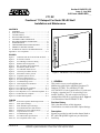
Figure 1. ADTRAN FT1 DP for Nortel DE-4E Shelf ... 1
Figure 2. P1 Switch Location ......................................... 5
Figure 3. FT1 DP Edge Connector Wiring .................... 6
Figure 4. Bantam Jack Arrangement .............................. 6
Figure 5. RS-232 (DB-9) Pin Assignments .................... 7
Figure 6. Introductory Menu Screen .............................. 8
Figure 7. FT1 DP Main Menu Screen ............................ 8
Figure 8. Current System Status Screen ......................... 9
Figure 9. Performance History Screen ......................... 10
Figure 10. Loopback Options Screen ............................. 10
Figure 11. Self-Test Options Screen .............................. 11
Figure 12. Provisioning Options Screen ........................ 11
Figure 13. Troubleshooting Screen ................................ 12
Figure 14. DSL Deployment Guidelines ........................ 13
Figure A-1. FT1 Loopbacks .......................................... A-1
Figure A-2. FT1 DP Network Loopback ....................... A-1
Figure A-3. FT1 DP CPE Loopback ............................. A-1
Figure A-4. FT1 Repeater #1 or # 2 Network Loopback . A-2
Figure A-5. FNID Network Loopback .......................... A-2
Figure A-6. FNID CPE Loopback ................................. A-2
TABLES
Table 1.
Table 2.
Table 3.
Table 4.
Table 5.
Table 6.
Table 7.
Table 8.
Table A-1.
Protected Loopback Mode Requirement ........ 2
SW1 Option Settings ....................................... 3
SW2 and SW3 Option Settings ....................... 4
Front Panel Indicators and Switches .............. 5
Definition of Screen Abbreviations ................ 7
Loop Insertion Loss Data .............................. 13
Troubleshooting Guide ................................. 14
FT1 DP Product Specifications .................... 15
FT1 Loopback Select Codes ...................... A-1
61245207L2-5C
FT1 DP
12
45207L
1
8
6 7 9 10
5
11
4
12
3
2
DSL
SX
DS1
ALM
LB
AP
L
O
C
R
E
M
R
S
2
3
2
DSO
O
U
T
I
N
R
X
T
X
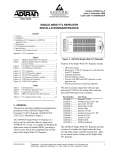
Figure 1. ADTRAN FT1 DP for Nortel DE-4E Shelf
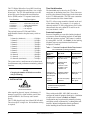
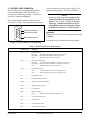
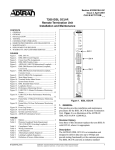
1. GENERAL
This practice serves as an Installation and
Maintenance guide for the ADTRAN Fractional T1
Dataport (FT1 DP). The ADTRAN FT1 DP
(P/N 1245207L2) is the Central Office (CO) unit used
to deploy a repeater-less FT1 circuit using 2-wire
metallic facilities. The unit occupies one slot in a
standard Nortel DE-4E (or equivalent) shelf. Figure 1
is an illustration of the ADTRAN FT1 DP.
Revision History
This is the third release of this document.
Clarifications were made to the SW1 Option Settings.
Description
Signals are provided to and from the channel bank or
RT, while 2B1Q HDSL signals are provided to the
local loop.
Section
61245207L2-5,
Issue
2
Trademarks: Any brand names
and
product names
included
in this document are
trademarks, registered trademarks, or trade names of their respective holders.
1
The FT1 Digital Subscriber Loop (DSL) local loop
operates as an independent subsystem, over a single
twisted pair. The FT1 DP communicates over this
twisted pair to the Fractional Network Interface
Device (FNID) and/or FT1 repeater listed below:
Part Number
Unit Description
1242041LX ................. T400 FNID Circuit Pack
1245201LX ................. T200 FNID Circuit Pack
1242042LX ................. T400 FNID Standalone
1242050L2 .................. FT1 Repeater
1245211LX ................. FT1 Repeater
The payload between FT1 DP and FNID is
programmable from the faceplate rotary switch as
follows:
2 channels (minimum) ..................... 128 kbps
3 channels ........................................ 192 kbps
4 channels ........................................ 256 kbps
5 channels ........................................ 320 kbps
6 channels ........................................ 384 kbps
7 channels ........................................ 448 kbps
8 channels ........................................ 512 kbps
9 channels ........................................ 576 kbps
10 channels ...................................... 640 kbps
11 channels ...................................... 704 kbps
12 channels (maximum) .................. 768 kbps
The system carries a small amount of overhead used
for maintenance and performance monitoring related
functions.
NOTE
Changing the number of DS0s does not affect
unit provisioning.
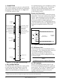
2. INSTALLATION
Time Slot Allocation
The bandwidth may be taken by the FT1 DP in
contiguous or alternating time slots. These slots must
not have other channel cards plugged in the slots taken
by the FT1 DP bandwidth. This will cause contention
on the transmit side of the channel bank.
The FT1 will not wrap around the channels at the end
of the channel bank. For example, if n is equal to 4
channels and the FT1 DP is plugged into slot 23 of the
channel bank, then only channels 23 and 24 can be
used, not channels 1 and 2.
Protected Loopback
Protected Loopback prevents false latching loopback
occurrences when the latching loopback is embedded
within the customer payload. This feature is enabled
by setting SW1-8 to ON. See Table 1 for the latching
loopback sequence requirement when Protected
Loopback is enabled.
Table 1. Protected Loopback Mode Requirement
T1E1.2/99-007R1 (Latching Loopback)
Function
Sequence
Byte Code
# of Received
Bytes
Clear existing
loopbacks
Transition in progress
(TIP) X0111010
Minimum of 35
TIP bytes
Identify device
to be looped
Loopback select
code (LSC)
X1010101 - OCU
X0110001 - CSU
X1000001 - NI
Minimum of 35
LSC bytes
Prepare loop,
Loopback enabled
send MAP code (LBE) X1010110
after 30 bytes
Minimum of 100
LBE bytes
Activate
loopback
Minimum of 35
FEV bytes
Far-end voice (FEV)
X1011010
Note: Minimum of 35 TIP bytes required to disable
established latching loopback.
X = don't care bit.
C A U T I O N !
SUBJECT TO ELECTROSTATIC DAMAGE
OR DECREASE IN RELIABILITY.
HANDLING PRECAUTIONS REQUIRED.
After unpacking the unit, inspect it for damage. If
damage is noted, file a claim with the carrier, then
contact ADTRAN. See Warranty and Customer
Service.
The FT1 DP plugs directly into a Nortel DE-4E shelf.
The unit occupies a single slot. No installation wiring
is required.
2
Three switch packs (SW1, SW2, SW3) are used to
configure the mode of operation for the unit. A definition
of each switch is shown in Table 2 and Table 3.
Configuration may be performed by manually selecting
each option switch, or alternatively, set through the craft
interface. Manual configuration must be performed
before installing the unit into the channel bank.
Section 61245207L2-5, Issue 3
61245207L2-5C
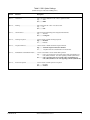
Table 2. SW1 Option Settings
(Default settings are indicated in bold typeface.)
Switch
Function
Description
SW1-1 ...... Code Select ............................................ SW1-1 On selects B8ZS line code. SW1-1 Off selects AMI.
Off .......... AMI
On .......... B8ZS
SW1-2 ...... Framing .................................................. SW1-2 Off selects SF. SW1-2 On selects ESF.
Off .......... SF
On .......... ESF
SW1-3 ...... Channel Select ....................................... Selects between Alternating and Contiguous DS0 channels.
Off .......... Alternate
On .......... Contiguous
SW1-4 ...... Latching Loopback ................................ Used to enable or disable latching loopbacks.
Off .......... Disabled
On .......... Enabled
SW1-5 ...... Loopback Timeout ................................. Used to enable or disable automatic loopback timeout.
Off .......... Automatic loopback timeout is disabled
On .......... Loopback timeout is enabled and set for 20 minutes.
SW1-6 ...... Dumb/Smart Channel Bank Enable ...... Used to select dumb or smart channel bank operation
Off .......... Unit is provisioned for an NT1 bank with a Smart Transmit/Receive
Unit (STRU) installed. Two-state signaling available (smart mode)
On .......... Unit is provisioned for an NT1 bank with a Transmit/Receive
Unit (TRU) installed. Four-state signaling available (dumb mode)
SW1-8 ...... Protected Loopback ............................... Used to enable or disable protective loopback.
Off .......... Disabled.
On .......... Enabled.
61245207L2-5C
Section 61245207L2-5, Issue 2
3
Table 3. SW2 and SW3 Option Settings
(Default settings are indicated in bold typeface)
Switch
Function
Description
SW3-4 ........... A/B Signaling for Channel 1 ....... Enables or Disables A/B Robbed Bit Signaling for Channel 1.
Off ........ A/B Signaling Disabled
On ......... A/B Signaling Enabled
SW3-3 ........... A/B Signaling for Channel 2 ....... Enables or Disables A/B Robbed Bit Signaling for Channel 2.
Off ........ A/B Signaling Disabled
On ......... A/B Signaling Enabled
SW3-2 ........... A/B Signaling for Channel 3 ....... Enables or Disables A/B Robbed Bit Signaling for Channel 3.
Off ........ A/B Signaling Disabled
On ......... A/B Signaling Enabled
SW3-1 ........... A/B Signaling for Channel 4 ....... Enables or Disables A/B Robbed Bit Signaling for Channel 4.
Off ........ A/B Signaling Disabled
On ......... A/B Signaling Enabled
SW2-8 ........... A/B Signaling for Channel 5 ....... Enables or Disables A/B Robbed Bit Signaling for Channel 5.
Off ........ A/B Signaling Disabled
On ......... A/B Signaling Enabled
SW2-7 ........... A/B Signaling for Channel 6 ....... Enables or Disables A/B Robbed Bit Signaling for Channel 6.
Off ........ A/B Signaling Disabled
On ......... A/B Signaling Enabled
SW2-6 ........... A/B Signaling for Channel 7 ....... Enables or Disables A/B Robbed Bit Signaling for Channel 7.
Off ........ A/B Signaling Disabled
On ......... A/B Signaling Enabled
SW2-5 ........... A/B Signaling for Channel 8 ....... Enables or Disables A/B Robbed Bit Signaling for Channel 8.
Off ........ A/B Signaling Disabled
On ......... A/B Signaling Enabled
SW2-4 ........... A/B Signaling for Channel 9 ....... Enables or Disables A/B Robbed Bit Signaling for Channel 9.
Off ........ A/B Signaling Disabled
On ......... A/B Signaling Enabled
SW2-3 ........... A/B Signaling for Channel 10 ..... Enables or Disables A/B Robbed Bit Signaling for Channel 10.
Off ........ A/B Signaling Disabled
On ......... A/B Signaling Enabled
SW2-2 ........... A/B Signaling for Channel 11 ..... Enables or Disables A/B Robbed Bit Signaling for Channel 11.
Off ........ A/B Signaling Disabled
On ......... A/B Signaling Enabled
SW2-1 ........... A/B Signaling for Channel 12 ..... Enables or Disables A/B Robbed Bit Signaling for Channel 12.
Off ........ A/B Signaling Disabled
On ......... A/B Signaling Enabled
4
Section 61245207L2-5, Issue 3
61245207L2-5C
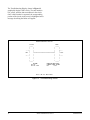
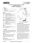
FT1 DP Option Selections
Configuration strap P1, illustrated in Figure 2, selects
FT1 DP settings.
By selecting -190 V, the FT1 DP can power up to two
FT1 repeaters and a locally-powered FNID.
The settings on the FT1 DP are encoded and
transmitted to the FNID once the circuit has achieved
synchronization.
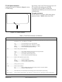
Faceplate Indicators
The FT1 DP has six faceplate LEDs which indicate
operational status. Table 4 defines these LEDs.
P1
o
o
o
-190 V
P1
o -137 V
o
o
Figure 2. P1 Switch Location
Table 4. Front Panel Indicators and Switches
Indicators
Description
DSL ........................Indicates four possible states of the quality of the DSL signal. (The signal quality has a provisionable
threshold of 2, 4, 6, or 8 dB above a 10-7 BER.)
Off ......................... No synchronization of FT1 DP and FNID
Yellow ................... Poor signal quality (below 2 dB above 10-7 BER)
Green .................... Good signal quality (above 2 dB above 10-7 BER)
Blinking ................ An error has been detected on the loop
DS1 .........................Indicates four possible conditions:
Green .................... The customer-side DS1 signal is present and synchronized
Yellow ................... Yellow alarm at customer side DS1
Off ......................... No customer-side DS1 signal present
Blinking ................ An error has been detected at FNID input
LB ...........................Indicates three possible loopback states:
Off ......................... No active loopbacks
Blinking ................ FNID or repeater is in loopback
On (solid) ............. Local (FT1 DP) loopback is active
SX ...........................Sealing current is present
ALM .......................Indicate alarm condition
On ......................... Alarm condition detected either locally (FT1 DP) or remotely (FNID)
Off ......................... No alarm condition detected
AP ...........................This LED will be On when Hardware Provisioning does not match software provisioning.
Rotary Switch .........Selects number of DS0 channels. (See subsection 1 of this practice for a description of time slot allocation.)
61245207L2-5C
Section 61245207L2-5, Issue 2
5
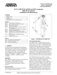
3. CONNECTIONS
The FT1 DP occupies one card slot in a Nortel DE-4E
shelf. Power signaling is provided to the card through
the backplane of the channel bank. See Figure 3 for
FT1 DP edge connector wiring.
A1
B1
A2
B2
A3
B3
A4
B4
A5
B5
5 V Ground
A6
B6
5 V Ground
A7
B7
A8
B8
DS0 Channel Rx Signal
A9
B9
DS0 Channel Tx Signal
A-Bit Tx Signaling Bus
A10
B10
B-Bit Tx Signaling Bus
DS0 Tx Bus Enable
A11
B11
DS0 Rx Clock
Signaling Bus Enable
A12
B12
DS0 Tx Clock
Rx Signaling Bus
A13
B13
Carrier Group Alarm
A-Bit Rx Signaling Strobe
A14
B14
B-Bit Rx Signaling Strobe
Transmit PCM
A15
B15
Receive PCM
A16
B16
A17
B17
A18
B18
Frame Ground
A19
B19
-48 V
A20
B20
-48 V Return
A21
B21
A22
B22
A23
B23
A24
B24
A25
B25
A26
B26
A27
B27
A28
B28
A29
B29
A30
B30
A31
B31
A32
B32
A33
B33
HDSL Ring
A34
B34
+5 V
A35
B35
DS0 Bit Clock
level problems that may occur at installation or during
operation of the FT1 HDSL system. The following
subsections describe additional testing features
conducted with the front panel Bantam jacks as well
as other faceplate features.
Bantam Jack Description
The front panel of the FT1 DP contains DS0 splitting
Bantam jacks. The metallic splitting jacks provide an
intrusive, signal interrupting access to the first DS0
channel. It is very important to know the direction of
the access provided by a metallic splitting jack.
Detailed descriptions of the FT1 DP Bantam jacks are
given in the following subsection. Figure 4 shows the
Bantam jack arrangement and details for specific
jacks.
FT1 DP
TX
1
DS0 Interface
Logic Level - NEAR
Channel Bank
Interface
RX
Figure 4. Bantam Jack Arrangement
DS0 Byte Clock
HDSL Tip
FT1 DP Bantam Jacks
The FT1 DP provides a set of dual Bantam jacks on
the front panel. These Bantam jacks allow connection
of a Tele-Path Instruments 108/109 RT II (or
equivalent) test set through one DS0 channel at
64 kbps for functions such as sending and receiving
bit error rate signals.
NOTE
The DS0 access jacks are logic level interface.
Figure 3. FT1 DP Edge Connector Wiring
4. DSL SYSTEM TESTING
The ADTRAN DSL system provides extensive ability
to monitor the status and performance of the DS1
signals and DSL loop signals. These features are
valuable in troubleshooting and isolating any system
FT1 DP Loopbacks
There are two loopbacks available to the FT1 DP.
FT1 DP network loopback loops the FT1 signal back
to the network. The FT1 DP CPE loopback loops the
FT1 signal back to the customer. The FT1 system
loopback capabilities are described in detail in
Appendix A of this practice.
1
Logic level NEAR loopback on the DS0 interface is toward the outside cable pair. The FT1 DP will support logic level FAR
loopback only in the presence of a BERT or loopback on the network end of the channel bank.
6
Section 61245207L2-5, Issue 3
61245207L2-5C
5. CONTROL PORT OPERATION
The FT1 DP provides a faceplate-mounted DB-9
connector that supplies an RS-232 interface for
connection to a controlling terminal. The pinout of
the DB-9 is illustrated in Figure 5.
is fixed at 8 data bits, no parity, and 1 stop bit. The
supported terminal type is VT-100 or compatible.
NOTE
If you are using a personal computer (PC)
with terminal emulation capability, be sure to
disable any power saving programs.
Otherwise, communication between the PC
and the HDSL unit may be disrupted, resulting
in misplaced characters or screen timeouts.
The terminal interface operates at data rates from
2.4 kbps to 19.2 kbps. The asynchronous data format
6
7
8
9
1
2
TXD (Transmit Data)
3
4
RXD (Receive Data)
5
SGN (Signal Ground)
Operation
Abbreviations used in the screen diagrams are detailed
in Table 5.
A terminal session is initiated by entering multiple
Figure 5. RS-232 (DB-9) Pin Assignments
Table 5. Definition of Screen Abbreviations
Abbreviation
Definition
ES ........................... Errored seconds
DS1 (SF) ....... Second in which a BPV or frame bit error occurs
DS1 (ESF) .... Second in which a BPV or CRC error occurs
DSL .............. Second in which a CRC error occurs
SES ......................... Severely errored seconds
DS1 (SF) ....... Second in which 1554 BPVs or 8 frame bit errors occur
DS1 (ESF) .... Second in which 1544 BPVs or 320 CRC errors occur
DSL .............. Second in which 165 CRC errors occur
UAS ........................ Unavailable seconds
DS1 ............... Second in which there is a loss of signal or sync
DSL .............. Second in which there is a loss of signal or sync
SF ............................ Superframe format
ESF ......................... Extended superframe format
B8ZS ....................... Bipolar with 8-zero substitution
AMI ........................ Alternate mark inversion
LBO ........................ Line build-out
BPV ........................ Bipolar violation
DS1 ............... Second in which a bipolar violation occurs
NIU ......................... T1 network interface unit
S/N .......................... Serial number
15M ........................ Fifteen-minute period
24H ......................... Twenty-four-hour period
61245207L2-5C
Section 61245207L2-5, Issue 2
7
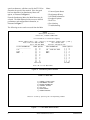
space bar characters, which are used by the FT1 DP to
determine the speed of the terminal. Once the speed
has been determined, an Introductory Menu will
appear, as illustrated in Figure 6.
From the Introductory Menu, the Main Menu may be
selected. The Main Menu provides access to detailed
performance and configuration information, as
illustrated in Figure 7.
Menu:
1. Current System Status
2. Performance History
3. ADTRAN Information
4. Loopback Options
5. Self-Test
6. Provisioning
7. Troubleshooting
The following screens can be accessed from the Main
ADTRAN
901 Explorer Boulevard
Huntsville, Alabama 35806-2807
For Information or Technical Support,
Normal Support Hours ( 7am - 7pm CST ) or Emergency Support Hours ( 7x24 )
Voice Toll Free: 800.726.8663
Fax: 256.963.6217
Voice: 256.963.8100
Internet: www.adtran.com
-----------------------------------------------------------------------------FT1-DP INFORMATION
SIGNAL QUALITY
FNID INFORMATION
SIGNAL QUALITY
-------------------[ ]
9
-------------------[ ]
9
S/N :
[ ]
8
S/N : DATA NOT AVAIL
[ ]
8
CLEI:
[ ]
7
CLEI:
[ ]
7
MANF:
/
[ ]
6
MANF:
[ ]
6
[ ]
5
[ ]
5
[ ]
4
[ ]
4
[ ]
3
[ ]
3
[ ]
2
[ ]
2
[ ]
1
[ ]
1
[ ]
0
[ ]
0
AT FT1-DP
AT FNID
Press “M” to view Main Menu.
Figure 6. Introductory Menu Screen
ADTRAN FT1 MAIN MENU
1)
2)
3)
4)
5)
6)
7)
CURRENT SYSTEM STATUS
PERFORMANCE HISTORY
ADTRAN INFORMATION
LOOPBACK OPTIONS
SELF-TEST
PROVISIONING
TROUBLESHOOTING
Choose a screen by pressing the corresponding number.
Figure 7. FT1 DP Main Menu Screen
8
Section 61245207L2-5, Issue 3
61245207L2-5C
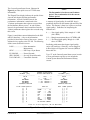
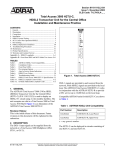
The Current System Status Screen, illustrated in
Figure 8, provides quick access to FT1 DP status
information.
The Elapsed Time display indicates the period of time
since the unit began collecting performance
information. At each 15-minute interval, the
performance information is transferred to the
15-minute performance data registers accessed from
the Performance History screen. At each 24-hour
interval, the performance data is transferred into the
24-hour performance data register also accessed using
this screen.
Figure 8 consolidates current information for the DSL
and DS1 interfaces. A key to the information
provided is found in the center of the screen. Arrows
indicate the key applies to the FT1 DP. The following
defines terms used on this screen:
LOSS ....................... Pulse Attenuation
Measurement
SYNC ...................... DSL Loop 1 Sync Status
ES 15M/24H ............ Errored Seconds
SES 15M/24H .......... Severely Errored Seconds
UAS 15M/24H ......... Unavailable Seconds
FT1-DP
NETWORK (DSL)
----------------------00 dB
NO
000/00000
000/00000
498/00498
LOOPBACKS INACTIVE
FT1-DP SIGNAL
[ ]
[ ]
[ ]
[ ]
[ ]
[ ]
[ ]
[ ]
[ ]
[ ]
QUALITY
9
8
7
6
5
4
3
2
1
0
NOTE
The first number is for the current 15-minute
period. The second number is for the current
24-hour period.
A measure of signal quality for each DSL loop is
graphically depicted on the bottom right and left of the
screen. The measure is from 0 to 9 (poor to excellent
signal quality). Guidelines for interpreting the
indicators are:
0 ......... Poor signal quality. Noise margin is ≤ 0 dB
(≈10-7 BER).
1-8 ...... Margin measurement above 10-7 BER in dB.
9 ......... Excellent signal quality. Margin is ≥ 9 dB
above 10-7 BER.
Predicting performance based upon signal quality
varies with each loop. Generally, a noise margin of
0 dB or higher will support a bit error rate (BER) of
better than 10-7.
Type “Z” at the Current System Status screen in order
to reset performance registers to zero at both the
Current System Status and Performance History
screens.
CURRENT SYSTEM STATUS
ELAPSED TIME 00:08:18
<LOSS
<SYNC
<- ES
15M/24H
<- SES 15M/24H
<- UAS 15M/24H
->
->
->
->
->
FNID DS1
-------------------FRAME
——>
SF
CODE
——>
AMI
LBO
——>
0 dB
BPV
——> 00000
ES
——> 00000
SES
——> 00000
UAS
——> 00000
ALARMS ——>
NONE
NO SEALING CURRENT
FNID
CUSTOMER (DSL)
------------------00 dB
NO
000/00000
000/00000
498/00498
LOOPBACKS INACTIVE
FNID
SIGNAL QUALITY
[ ]
9
[ ]
8
[ ]
7
[ ]
6
[ ]
5
[ ]
4
[ ]
3
[ ]
2
[ ]
1
[ ]
0
Press “Z” to zero registers, “M” for Main Menu.
Figure 8. Current System Status Screen
61245207L2-5C
Section 61245207L2-5, Issue 2
9
The Performance History Screen displays 15-minute
and 24-hour registers for several points in the circuit.
Figure 9 depicts the Performance History Screen.
Figure 10 depicts the FT1 DP Loopback Options
Screen. Loopback may be initiated or terminated
using this screen. A status of current loopback
conditions also appear.
PERFORMANCE
24 HOUR REGISTERS
---ES---SES-00000 00000
-1: ----- -----2: ----- -----3: ----- -----4: ----- -----5: ----- -----6: ----- -----7: ----- -----
HISTORY <VIEW 2 - FNID DS1 RECEIVER>
15 MINUTE REGISTERS
--ES-SES-----------ES-SES<---CURRENT--->
000 000
<--->
-1: --- ---17: --- --|
|
-2: --- ---18: --- --|
|
-3: --- ---19: --- --|
|
-4: --- ---20: --- --|PREVIOUS |
-5: --- ---21: --- --|
|
-6: --- ---22: --- --<-|
-7: --- ---23: --- --|
-8: --- ---24: --- --VIEW LOCATION DIAGRAM
|
-9: --- ---25: --- --|
-10: --- ---26: --- ---->|F|
|F|-->
|
-11: --- ---27: --- --|T|
|N|
|
-12: --- ---28: --- --|1|<-3-------DSL-----4->|I|
|
-13: --- ---29: --- --|D|
|D|
|
-14: --- ---30: --- --<--|P|
| |<-2
|
-15: --- ---31: --- ----> -16: --- ---32: --- --Press view number to select view, “M” to return to Main Menu
Figure 9. Performance History Screen
LOOPBACK OPTIONS
FT1-DP
FNID
_____
_____
|
|
|
|
|
|
|
|
--->|
|
|
|<--|
|
|
|
NET |
|<===========================>|
| CUST
|
|
|
|
<---|
|
|
|--->
|
|
|
|
|
|
|
|
|_____|
|_____|
1)
2)
3)
4)
LOOPBACK
LOOPBACK
LOOPBACK
LOOPBACK
TO
TO
TO
TO
NETWORK
CUSTOMER
NETWORK
CUSTOMER
AT
AT
AT
AT
FT1-DP
FT1-DP
FNID
FNID
=INACTIVE
=INACTIVE
=INACTIVE
=INACTIVE
Press corresponding number to toggle loopback option.
Press “M” for Main Menu.
Figure 10. Loopback Options Screen
10
Section 61245207L2-5, Issue 3
61245207L2-5C
Figure 11 depicts the Self-Test Options Screen. A
test of the FT1-DP and the FNID may be initiated
from this screen.
Figure 12 shows the Provisioning Options screen.
Settings for all provisioning options may be
configured via the provisioning screen.
SELF-TEST
Press “S” to initiate FT1-DP and FNID self-tests.
Press “M” to return to the Main Menu.
Figure 11. Self-Test Options Screen
PROVISIONING
___________________________________________________ ______________________
|
|
|
|
PROVISIONS
CURRENT SETTINGS
|
HARDWARE SETTINGS |
|
-----------------------------------------|
----------------- |
|
1. DS1 (FNID) LINE CODE =
B8ZS
|
B8ZS
|
|
2. DS1 (FNID) FRAMING
=
ESF
|
ESF
|
|
3. DS1 (FNID) TX LEVEL =
0 dB
|
|
|
4. LOOPBACK TIMEOUT
=
20 MIN
|
20 MIN
|
|
5. LATCHING LOOPBACK
=
ENABLED
|
ENABLED
|
|
6. DSO SEQUENCE
=
CONTIGUOUS
|
CONTIGUOUS
|
|
7. NUMBER OF DSOS
=
12 (768Kbps)
|
12 (768Kbps)
|
|
8. SIGNALING ENABLED:
|
|
|
000000000000
|
000000000000
|
|
CHANNELS
1
12
|
1
12
|
|
“1” INDICATES SIGNALING ENABLED.
|
|
|___________________________________________________|______________________|
Press:
“n”
“H”
“I”
“M”
—
—
—
—
to
to
to
to
change corresponding provision (ex. “2” for FRAMING)
copy hardware settings to current settings
implement and save current setting changes
return to the main menu
Figure 12. Provisioning Options Screen
61245207L2-5C
Section 61245207L2-5, Issue 2
11
The Troubleshooting Display, shown in Figure 13,
graphically depicts a DSL circuit. The unit monitors
red, yellow, and blue alarm conditions in the circuit.
Once a fault location is suspected, the corresponding
portion of the circuit on the screen is highlighted and a
message describing the failure will appear.
TROUBLESHOOTING DISPLAY
FT1-DP
FNID
_____
_____
|
|
|
|
|
|
|
|
--->|
|
|
|<--|
|
|
|
NET |
|<===========================>|
| CUST
|
|
|
|
<---|
|
|
|--->
|
|
|
|
|
|
|
|
|_____|
|_____|
ALARMS:
FT1-DP
FT1-DP RED
PROBLEM INDICATED:
CHANNEL BANK ALARM
DSL
LOSS
Press “M” for Main Menu.
Figure 13. Troubleshooting Screen
12
Section 61245207L2-5, Issue 3
61245207L2-5C
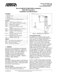
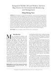
6. DSL DEPLOYMENT GUIDELINES
The ADTRAN FT1 DSL system is designed to
provide Fractional DS1 based services over loops
designed to comply with Carrier Service Area (CSA)
guidelines. CSA deployment guidelines are given
below.
1. All loops are non-loaded only.
2. For loops with 26-AWG cable, the maximum loop
length including bridged tap lengths is 9 kft.
3. For loops with 24-AWG cable, the maximum loop
length including bridged tap lengths is 12 kft.
4. Any single bridged tap is limited to 2 kft.
5. Total bridged tap length is limited to 2.5 kft.
6. The total length of multi-gauge cable containing
26-AWG cable must not exceed
12 - {(3*L 26 )/9} - L BTAP (in kft)
L26
=
LBTAP
=
Frequency (Hz)
Maximum Loss (dB)
An approximation for the maximum amount of
wideband noise on a DSL local loop as measured by a
50 kbps filter is ≤ 31 dBrn.
An approximation for the maximum level of impulse
noise as measured using a 50 kbps filter on a DSL
loop is ≤ 50 dBrn.
NOTE
These approximations are to be used as
guidelines only and may vary slightly on
different loops. Adhering to the guidelines
should produce performance in excess of 10-7
BER.
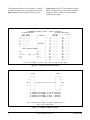
This deployment criteria is summarized in the chart
shown in Figure 14.
12
WORKING LENGTH OF 24 GAUGE (OR COARSER) CABLE (KFT)
Table 6. Loop Insertion Loss Data
3000 .................................... 12.0
10,000 .................................... 15.0
50,000 .................................... 25.5
100,000 .................................... 30.0
150,000 .................................... 32.75
200,000 .................................... 35.25
Total length of 26-AWG cable
excluding bridged taps (in kft)
Total length of all bridged taps
(in kft)
11
Recommended maximum local loop loss information
for PIC cable at 70°F, 135Ω resistive termination, is
provided in Table 6.
INVALID DSL CABLE LENGTHS
10
TOTAL
BRIDGED
2.5
TAP
2.0
1.5
LENGTH
1.0
(KFT)
0.5
0.0
9
8
7
6
5
4
3
2
VALID DSL CABLE LENGTHS
1
0
0
1
2
3
4
5
6
7
8
9
WORKING LENGTH OF 26 GAUGE CABLE (KFT)
Figure 14. DSL Deployment Guidelines
61245207L2-5C
Section 61245207L2-5, Issue 2
13
7. MAINTENANCE
The ADTRAN FT1 DP requires no routine
maintenance. In case of equipment malfunction, use
the features supplied with the FT1 DP to help locate
the source of the problem.
ADTRAN does not recommend that repairs be
performed in the field. Repair services may be
obtained by returning the defective unit to the
ADTRAN Customer Service RMA Department.
8. TROUBLESHOOTING PROCEDURES
Use Table 7 to troubleshoot the FT1 DP.
9. PRODUCT SPECIFICATIONS
Specifications for the FT1 DP are provided in
Table 8.
10. WARRANTY AND CUSTOMER SERVICE
ADTRAN will replace or repair this product within 10
years from the date of shipment if it does not meet its
published specifications or fails while in service (see
ADTRAN Carrier Networks Equipment Warranty,
Repair, and Return Policy and Procedure, document
60000087-10A).
Contact Customer and Product Service (CAPS) prior
to returning equipment to ADTRAN.
For service, CAPS requests, or further information,
contact one of the following numbers:
ADTRAN Sales
Pricing/Availability
(800) 827-0807
ADTRAN Technical Support
Presales Applications/Postsales Technical Assistance
(800) 726-8663
Standard hours: Monday-Friday, 7 a.m. - 7 p.m. CST
Emergency hours: 7 days/week, 24 hours/day
ADTRAN Repair/CAPS
Return for Repair/Upgrade
(256) 963-8722
Repair and Return Address
ADTRAN, Inc.
CAPS Department
901 Explorer Boulevard
Huntsville, Alabama 35806-2807
Table 7. Troubleshooting Guide
Condition
Solution
All front panel indicators are off.
1.
2.
3.
Verify that the FT1 DP is properly seated in the housing.
Make sure power supply feeding the FT1 DP is good.
If Steps 1 and 2 pass, replace the FT1 DP.
Power OK but does not achieve Loop Sync (DSL LED is off).
1.
Verify that the loop conforms with CSA guidelines
(not too long, etc.).
Verify that the Loop Loss at 200 kHz is not greater
than 36 dB.
Verify that noise on the DSL Loop is within acceptable
limits.
If Steps 1 through 3 pass and Loop Sync is still not
available, replace the unit with an FT1 DP unit known to be
in good working condition.
2.
3.
4.
14
Section 61245207L2-5, Issue 3
61245207L2-5C
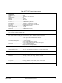
Table 8. FT1 DP Product Specifications
Loop Interface
Modulation Type ............................... 2B1Q
Mode ................................................. Full Duplex, Echo Cancelling
Number of Pairs ................................ One
Bit Rate ............................................. 784 kbps
Baud Rate .......................................... 392K baud
Service Range ................................... Defined by Carrier Service Area Guidelines
Loop Loss .......................................... 36 dB maximum @ 200 kHz
Bridged Taps ..................................... Single taps < 2 kft, total taps < 2.5 kft
Performance ...................................... Compliant with Bellcore TA-NWT-001210
Return Loss ....................................... 20 dB (40 kHz to 200 kHz)
DSL Tx Signal Level ........................ 13.5 dBm
Input Impedance ............................... 135Ω
Return Loss ....................................... 20 dB (40 kHz to 200 kHz)
DS1 Facility Interface
Fully compatible with Nortel DE-4E shelf
Power
Tested with the ADTRAN FT1 Repeater (P/N 1245211L1) and the ADTRAN FNID (P/N 1245201L1)
Total Power ....................................... -48 VDC @ 125 mA with FNID
-48 VDC @ 215 mA with FNID and FT1 Repeater
-48 VDC @ 300 mA with Local Power FNID and two FT1 Repeaters
FT1 DP Power Dissipation ............... 3.7 watts with FNID
5.2 watts with FNID and FT1 Repeater
6.1 watts with Local Power FNID and two FT1 Repeaters
Span Power ....................................... 137 V or -190 VDC (nominal)
Fusing 1.00 A (not field-replaceable)
Clock Sources
Clock Sources ................................... Internal, DS1 Derived
Internal Clock Accuracy ................... ± 25 ppm, (exceeds Stratum 4). Meets T1.101 timing requirements.
Tests
Diagnostics ........................................ Self-Test, Local Loopback (FT1 DP), Remote Loopback (FNID)
Mechanical
Dimensions ....................................... 6.2" High, 1.1" Wide, 10.2" Deep, 16 ounces, nominal
Plugs into Nortel DE-4E (or equivalent) shelf
Environment
Temperature ...................................... Operating (Standard): -40° to +70°C; Storage: -40° to +85°C
Relative Humidity ............................. Up to 95%, non-condensing
Part Number ....................................... 1245207L2
61245207L2-5C
Section 61245207L2-5, Issue 2
15
16
Section 61245207L2-5, Issue 3
61245207L2-5C
Appendix A
FT1 Loopbacks
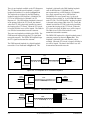
GENERAL
back to the network. The FT1 DP CPE loopback
loops the FT1 signal back to the customer.
This Appendix is an overall reference to the loopback
capabilities of the ADTRAN Fractional T1 system.
Included in this Appendix is a description of the FT1
loopbacks and the methods for activating the FT1
loopbacks.
The FT1 DP network loopback is a digital loopback
toward the CO (see Figure A-2). This loopback is
initiated by the OCU latching loopback command
(N1010101), or by the craft interface, when available.
The OCU latching loopback code is detected in the
primary DS0 of the FT1 circuit (the channel where the
FT1 DP is physically installed) to control the FT1
circuit looping. When the FT1 circuit is looped, all
DS0s in use will be looped back toward the network.
The DS0s will be transmitted on to the customer.
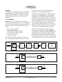
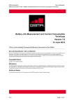
FT1 LOOPBACKS
Figure A-1 shows the application from the central
office (CO) to customer premises. The FT1 Repeaters
are shown for convenience and are not necessary parts
of the FT1 network. The loopbacks shown are as
follows:
A.
B.
C.
D.
E.
F.
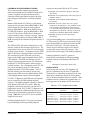
The FT1 DP CPE loopback is a digital loopback
toward customer premises as shown in Figure A-3.
This loopback is initiated by the REM LBK button on
the FNID, or by the craft interface when available.
When the FT1 circuit is looped, all DS0s in use will
be looped back toward the customer. All DS0s in use
will be filled with all 1s and sent toward the network.
FT1 DP network loopback
FT1 DP CPE loopback
FT1 Repeater # 1 network loopback
FT1 Repeater # 2 network loopback
FNID network loopback
FNID CPE loopback
There are two loopbacks available to the FT1 DP.
The FT1 DP network loopback loops the FT1 signal
DSX-1
Interface
FT1
Repeater
FT1
Repeater
FT1 DP
#1
Central Office
A
D4
Channel Bank
B
FNID
T1 NIU
#2
D
C
E
Customer
Premises
Equipment
F
Figure A-1. FT1 Loopbacks
DSX-1
Interface
FT1 DP
DS1
Interface
HDSL
FNID
Local Loop
Central Office
Customer Premises
D4
Channel Bank
Figure A-2. FT1 DP Network Loopback
DSX-1
Interface
FT1 DP
DS1
Interface
HDSL
FNID
Local Loop
Central Office
Customer Premises
D4
Channel Bank
Figure A-3. FT1 DP CPE Loopback
61245207L2-5C
Section 61245207L2-5, Issue 3
A-1
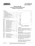
There is one loopback available to the FT1 Repeaters.
The FT1 Repeater Network loopback is a digital
loopback toward the CO as shown in Figure A-4.
The loopbacks are initiated by the DDS latching
loopback codes for NEI Position 1 (N1000001) for
FT1 #1 or NEI Position 2 (N100001) for FT1
Repeater # 2. The NEI latching loopback is detected
in the primary DS0 of the FT1 circuit, the channel
where the FT1 DP is physically installed, to control
the looping of the FT1 circuit. When the FT1 circuit
is looped, all DS0s in use will be looped. The DS0s in
use will also be transmitted on to the customer.
loopback is initiated by the DDS latching loopback
code for NEI Position 1 (N1000001) for a
non-repeatered loop, or NEI Position 2 (N1000001)
for a single repeater loop or by NEI Position 3
(N1000001) for a two repeater loop; by the craft
interface when available, or by the REM LBK button
at the FT1 DP. The NEI Position 1 latching loopback
is detected in the primary DS0 of the FT1 circuit (the
channel in which the FT1 DP is physically installed),
to control the looping of the FT1 circuit. When the
FT1 circuit is looped, all DS0s in use will be looped.
The DS0s in use will be filled with all 1s and
transmitted toward the customer.
There are two loopbacks available to the FNID. The
FNID network loopback loops the FT1 signal back
toward the network. The FNID CPE loopback loops
the FT1 signal back toward the customer.
The FNID CPE loopback is a digital loopback toward
customer premises as shown in Figure A-6. This
loopback is initiated by the craft interface, when
available. When the FT1 circuit is looped, all DS0s in
use will be looped. The data in the DS0s in use will
be transmitted toward the network.
The FNID network loopback is a digital loopback
toward the CO as illustrated in Figure A-5. This
HDSL
DSX-1
Interface
Central Office
DS1
Interface
FT1
Repeater
# 1 or 2
FT1 DP
FNID
Customer Premises
Local Loop
D4
Channel Bank
Figure A-4. FT1 Repeater # 1 or 2 Network Loopback
DSX-1
Interface
FT1 DP
FNID
HDSL
Local Loop
Central Office
DS1
Interface
Customer Premises
D4
Channel Bank
Figure A-5. FNID Network Loopback
DSX-1
Interface
FT1 DP
Central Office
HDSL
FT1-NID
Local Loop
DS1
Interface
Customer Premises
D4
Channel Bank
Figure A-6. FNID CPE Loopback
A-2
Section 61245207L2-5, Issue 3
61245207L2-5C
LOOPBACK ACTIVATION/DEACTIVATION
This section describes loopback activation and
deactivation methods for the ADTRAN Fractional T1
system. Loopback activation and deactivation is
controlled with the push-button located on the front
panel, through craft interface, or latching loopback
codes.
Both the FNID and the FT1 DP have a push-button
located on the front panel labeled REM LBK or RLB
which controls the activation of remote loopback.
Pressing REM LBK or RLB on the FNID activates
FT1 DP CPE loopback. Pressing REM LBK or RLB
on the FT1 DP activates FNID network loopback or
repeater loopback when a repeater is present. Remote
loopback is deactivated by pressing the REM LBK or
RLB or waiting for the 20-minute loopback timeout, if
enabled.
The FNID and FT1 DP (when available) have a craft
interface located on the front panel of the device. The
craft interface allows access to the FT1 device through
an RS-232-type interface. All loopbacks for the FNID
and FT1 DP can be controlled from the craft interface.
The craft interface on the FNID can activate and
deactivate the FNID network loopback and the FNID
CPE loopback. The FNID craft interface can also
remotely activate and deactivate the FT1 DP network
loopback, FT1 DP CPE loopback, and the repeater
network loopback. The craft interface on the FT1 DP
can activate and deactivate the FT1 DP network
loopback and the FT1 DP CPE loopback. The FT1
DP craft interface can also remotely activate and
deactivate the FNID network loopback and the FNID
CPE loopback and the repeater network loopback.
FT1 DP, FT1 Repeater, and FNID network loopbacks
can be activated by the DDS latching loopback
sequence. The latching loopback sequence is detected
in the primary DS0 of the FT1 system. When the
loopback is activated on the device, the whole FT1
bandwidth is looped. The FT1 DP, FT1 Repeater, and
FNID each respond to a different loopback select code
allowing for sectionalization of the network during
testing. Table A-1 is a list of FT1 devices and their
loopback select codes.
Latching loopbacks for the FT1 system are activated
by transmitting the following latching loopback
61245207L2-5C
sequence in the primary DS0 of the FT1 system:
A. Minimum of 35 transition in progress (TIP) bytes
(N0111010).
B. Minimum of 35 loopback select code (LSC) bytes as
defined in Table 1.
C. Minimum of 100 loopback enable (LBE) bytes
(N1010110).
D. Minimum of 35 all 1s bytes (S1111111), plus a
minimum of 100 LBE bytes. (N-1) iterations, where
N is the number of channel units of the same type
(i.e., same LSC) that lie between the test center and
the loopback to be operated. This step is only used
when there are identical channel units in tandem.
E. Minimum of 32 far end voice (FEV) bytes
(N1011010).
A 25-second watchdog timer is activated between the
35 TIP bytes and 35 LSC bytes, between the 35 LSC
bytes and 100 LBE bytes, and between the 100 LBE
bytes and 32 FEV bytes. The timer requires the
correct receipt of the latter sequences less than 25
seconds after receipt of the prior sequence. This
prevents inadvertent setting of the latching loopbacks.
Latching loopbacks for the FT1 system are
deactivated by transmitting the following latching
loopback sequence in the primary DS0 of the FT1
system:
Minimum of 35 TIP bytes (N0111010).
LOOPUP STATE
In the loopup state, the active FT1 loopback will
provide a continuous loop for the FT1 bandwidth.
The data flow is continuously monitored for the loop
deactivation commands to deactivate the loopbacks.
Also, a 20-minute loopback timeout is checked. If the
loopback timeout is enabled, any loopback that is in
the loopup state for 20 minutes will be deactivated.
Table A-1. FT1 Loopback Select Codes
FT1 Device
Loopback Select
Code Name
Loopback Select
Code Byte
FT1 DP .............................. OCU loopback .................. N1010101
FT1 Repeater #1 ................ NEI Position 1 loopback ... N1000001
FT1 Repeater #2 ................ NEI Position 2 loopback ... N1000001
FNID without repeater ...... NEI Position 1 loopback ... N1000001
FNID with one repeater .... NEI Position 2 loopback ... N1000001
FNID with two repeaters .. NEI Position 3 loopback ... N1000001
Section 61245207L2-5, Issue 3
A-3