1
MultiModemManager
MR4800E Rack Controller
Owner’s Manual
MR4800E Rack Controller
Owner’s Manual
P/N 82042403, Revision D
This publication may not be reproduced, in whole or in part without prior expressed written
permission from Multi-Tech Systems reserved.
Copyright © 1996, by Multi-Tech Systems, Inc.
Multi-Tech Systems, Inc. makes no representation or warranties with respect to the contents hereof
and specifically disclaims any implied warranties of merchantability or fitness for any particular
purpose. Furthermore, Multi-Tech Systems, Inc. reserves the right to revise this publication and to
make changes from time to time in the content hereof without obligation of Multi-Tech Systems, Inc.
to notify any person or organization of such revisions or changes.
Revision
Description
B
(09/30/96)
Manual revised to include World Wide Web Browser
interface information.
C
(12/16/96)
Manual revised to include new commands and technical
and editorial information.
D
(9/15/97)
Manual revised to include new commands and technical
and editorial information.
Trademarks
Multi-Tech, MultiModem, MultiModemII, MultiModemManager and the Multi-Tech logo are trademarks
of Multi-Tech Systems, Inc.
Multi-Tech Systems, Inc.
2205 Woodale Drive
Mounds View, Minnesota 55112
(612) 785-3500 or (800) 328-9717
U.S. Fax (612) 785-9874
Technical Support (800) 972-2439
BBS (612) 785-3702 or (800) 392-2432
Fax Back (612) 717-5888
Internet Address: http://www.multitech.com
Contents
Chapter 1 - Introduction & Description
1.1
1.2
1.3
1.4
Introduction .......................................................................................................................................... 6
Product Description ............................................................................................................................. 6
Features ............................................................................................................................................... 6
Specifications ....................................................................................................................................... 7
Chapter 2 - Hardware Installation & Quick Starts
2.1
2.2
2.3
2.4
2.5
2.6
2.7
Introduction ........................................................................................................................................ 10
Battery Warning ................................................................................................................................. 10
Hardware Installation Procedure ........................................................................................................ 11
Ethernet Cabling ................................................................................................................................ 11
Serial Cabling .................................................................................................................................... 11
Quick Starts ....................................................................................................................................... 12
2.6.1
MR4800E Quick Start ......................................................................................................... 12
2.6.2
Supervisor Console Quick Start ......................................................................................... 12
Supervisor Console Configuration ..................................................................................................... 13
Chapter 3 - Hardware Operation
3.1
3.2
3.3
3.4
3.5
3.6
3.7
3.8
3.9
Introduction ........................................................................................................................................ 16
Security .............................................................................................................................................. 16
File System ........................................................................................................................................ 16
3.3.1
Event Files .......................................................................................................................... 16
SNMP Interface ................................................................................................................................. 17
Command Line Interface .................................................................................................................... 17
Telnet Interface .................................................................................................................................. 18
Web Browser Interface ...................................................................................................................... 18
3.7.1
Logging In ........................................................................................................................... 18
3.7.2
Getting Modem Information ................................................................................................ 18
3.7.3
Controlling Modems ............................................................................................................ 18
3.7.4
Web Interface Limitations ................................................................................................... 18
FTP Interface ..................................................................................................................................... 19
PPP Interface ..................................................................................................................................... 19
Chapter 4 - Commands
4.1
4.2
4.3
4.4
4.5
Parameter Descriptions ..................................................................................................................... 22
Commands Listed by Function .......................................................................................................... 23
Commands Listed by Security Level ................................................................................................. 26
Command Reference ......................................................................................................................... 28
Error Messages ................................................................................................................................. 52
Chapter 5 - Troubleshooting
5.1
5.2
5.3
5.4
5.5
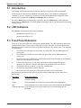
Introduction ........................................................................................................................................ 56
LED Indicators ................................................................................................................................... 56
Front Panel Indicators ........................................................................................................................ 56
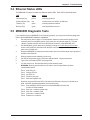
Ethernet Status LEDs ........................................................................................................................ 57
MR4800E Diagnostic Tests ................................................................................................................ 57
iii
Chapter 6 - Service, Warranty, & Tech Support
6.1
6.2
6.3
6.4
Service ............................................................................................................................................... 60
Limited Warranty ................................................................................................................................ 60
The Multi-Tech BBS ........................................................................................................................... 61
On-Line Upgrade via Flash PEROM and FLASHPRO Software ....................................................... 62
Index
iv
MultiModemManager
Chapter 1 - Introduction & Description
MR4800E Owner’s Manual
1.1 Introduction
This manual is intended to provide the information needed for field installation of a Multi-Tech
MR4800E Rack Controller Module (henceforth, MR4800E) into a previously-installed and operational
CC4800 MultiModemManager rack. The CC4800 is shipped standard without an MR4800E; this
manual documents the installation of an optional MR4800E.
1.2 Product Description
The MR4800E contains the processor and memory for intelligent SNMP management of the modems
in the rack. The front panel contains an RJ45 connection for Ethernet UTP attachment to a TCP/IP
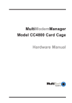
Ethernet network and a 9-pin serial connection for PPP attachment to a remote TCP/IP network. The
front panel provides 16 two-color LEDs for MR4800E card status and 4 Ethernet status LEDs.
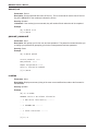
The MR4800E Rack Controller Module front panel is shown below.
MultiModemManager
ETHERNET
Serial Port
Reset
Button
MR4800E
Controller
Figure 1-1. MR4800E Rack Controller Module front panel
1.3 Features
The MR4800E is an optional part of the MultiModemManager system, Multi-Tech System’s highdensity intelligent modem/rack facility with network management capability. When you have installed
the MultiModemManager hardware and software, you will gain centralized modem rack
management to control modems, continuously monitor connections, log the data, and report fault
events.
6
Chapter 1 - Introduction & Description
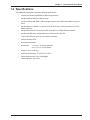
1.4 Specifications
The MR4800E is designed to meet the following specifications:
•
contains one Motorola MC68360 25 MHz microprocessor
•
provides 8 MB of RAM for volatile storage
•
provides 2 MB of flash RAM: 1 MB for program space and 1 MB for nonvolatile file system
space
•
provides Ethernet 10Base-T connector which is an RJ-45 for LAN connection to a TCP/IP
Ethernet network
•
provides EIA RS-232C connector for PPP connection to a TCP/IP Ethernet network
•
provides one RS-232C configuration port out of the back of the rack
•
16 two-color LEDs for quick view of modem card status
•
4 Ethernet status LEDs
•
Recessed reset button
•
Dimensions:
•
Weight: 1.0 Lbs. (0.45 Kg.)
•
Operating Temperature: 00 to 500 (320 to 1200 F)
•
Power Requirements: 60 Hz, 600mA@5V
•
Limited Warranty: Five years
1.75 x 4.2 x 15 inches (HxWxD)
4.2 x 11.5 x 37.4 cm (HxWxD)
7
MR4800E Owner’s Manual
8
MultiModemManager
Chapter 2 - Hardware Installation & Quick Starts
MR4800E Owner’s Manual
2.1 Introduction
This chapter provides the information needed to install your MR4800E Rack Controller into a Model
CC4800 MultiModemManager Rack. This equipment should only be installed by properly qualified
service personnel.
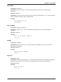
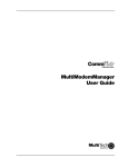
The MR4800E is illustrated below ( shown with the factory defualt configuration settings),
LEDs
Flash ROMs
Connector
CPU
U4
U5
U7
U6
To
back
panel
config/
debug
port
Test Jumper
Reset
Button
Ethernet
connector
Ribbon connector
Memory SIMMs
Figure 2-2. MR4800E Rack Controller Card
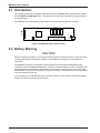
2.2 Battery Warning
CAUTION
Danger of explosion if battery is incorrectly replaced. Replace only with the same or equivalent type
recommended by the manufacturer. Dispose of used batteries according to the manufacturer’s
instructions.
The MR4800E Controller circuit board includes a battery that maintains the MR4800E’s setup
information when the MultiModemManager is turned off or disconnected from power. The battery can
maintain the setup information for approximately 10 years with no external power, and longer when
the MR4800E is turned on and operating normally. This battery is soldered onto the circuit board and
cannot be replaced by the user.
If, for some reason, the MR4800E’s battery should fail, please contact Multi-Tech Technical Support
at (800) 972-2439 for replacement instructions.
10
Chapter 2 - Hardware Installation & Quick Starts
2.3 Hardware Installation Procedure
To install a MR4800E, perform the following steps.
Note:
Step
Procedure
1.
Unpack the MR4800E from its packaging and perform a visual inspection of the hardware. If
you are concerned about the condition of your MR4800E, call Technical Support.
2.
Remove the blank controller panel or your MR4800 controller from the CC4800 rack. The
MR4800 and MR4800Es are hot-swappable.
3.
Holding the MR4800E by its U-bolt and the bottom panel, place the MR4800E into the open
slot of the CC4800 rack. Make sure the side rails of the MR4800E mate properly with the
plastic guides of the CC4800.
4.
Slide the MR4800E into the CC4800 rack until you feel the MR4800E connector contacts the
socket at the back of the CC4800 chassis.
5.
Tighten the MR4800E retaining screw.
6.
Turn the PS4800 power switch On (to the | position).
7.
Observe the PS4800 "Outputs Good” LED. If not lit, refer to Chapter 5 of this manual. If lit,
proceed with MultiModemManager operation (Chapter 4 of MultiModemManager Owner’s
Manual).
A self-test is run each time the MultiModemManager is powered on. Refer to Chapter 5 of the
MultiModemManager Owner’s manual for more details on the power on self-test.
2.4 Ethernet Cabling
The CC4800 rack front panel contains one female RJ-45 connector. This connector is used to
connect the MR4800E to an Ethernet network running TCP/IP. This connector must be connected to
the TCP/IP network that the management console (running the MultiModemManager software or
optionally, a third-party SNMP manager) is to be run on in order for the MR4800E to be configured.
2.5 Serial Cabling
If you wish to connect the CC4800 rack to the TCP/IP network using a serial link (i.e., via PPP or
SLIP) instead of using the Ethernet link, the 9-pin connector on the front panel of the MR4800E can
be used.
There is a 25 pin RS-232 port located behind the power supply on the back of the CC4800 rack that
is used for performing diagnostics and configuration.
11
MR4800E Owner’s Manual
2.6 Quick Starts
2.6.1 MR4800E Quick Start
Follow the steps below to configure your MR4800E.
Note:
1.
Power down your CC4800 rack.
2.
Insert the MR4800E into your CC4800 rack.
3.
Plug one end of the Ethernet cable in the Ethernet connector on the front of the MR4800E
and the other end in the Ethernet connector in the wall.
4.
Run MultiExpress (or any data comm package) at 115,200 with no flow control. Connect the
COM Port associated with the data comm package to the RS-232 port on the back of the
CC4800 rack.
5.
Turn the power on for the CC4800 rack and for the terminal. If the power is already on, press
the Reset Button on the MR4800E front panel with the end of a paper clip.
6.
You should see a screen that says "Welcome to the MultiModemManager MR4800E" and a
DOS prompt.
7.
At the userid prompt, type "supervisor"
8.
At the password prompt, type "supervisor"
9.
The message, "MultiModemManager MR4800E Environment setup" is displayed. You will be
prompted to enter the IP address of the MR4800E (i.e., IP address assigned to you by your
network administrator), default Trap IP address (i.e., IP address of the Supervisor), default
gateway IP address (i.e., IP address of the local router, if any), subnet mask, and community
strings.
10.
You will be prompted to change the supervisor user id and password.
11.
Reset the MR4800E by pressing the reset button on the front with a paper clip or power the
rack off and on.
Do not hit a key to start manually. Allow the MR4800E to start automatically.
12.
Every time after this, the MR4800E will start automatically when you power up the rack.
2.6.2 Supervisor Console Quick Start
12
1.
On the supervisor console, install the MultiModemManager software (see
MultiModemManager Owner's Manual for more information).
2.
Install the Newt TCP/IP package.
3.
After the installation, run the MultiModemManager software.
4.
Click on Setup | SNMP | Mode | Supervisor.
5.
Click on the Yes button when you are asked if you are sure.
6.
In the Modem Group window, click on the World icon.
7.
Click on the Add button.
8.
Type the IP address of the MR4800E (the same one you used in step 9 of the MR4800E
Quick Start).
9.
Click on OK.
10.
The IP will "turn green" indicating the supervisor console is able to communicate with the
remote MR4800E.
11.
System configuration is done using the supervisor console as specified in Section 2.7.
Chapter 2 - Hardware Installation & Quick Starts
2.7 Supervisor Console Configuration
1.
Set up security accounts by using the Security DB Editor (part of the MultiModemManager
software).
2.
Set up configuration files using the Configuration Manager (part of the MultiModemManager
software).
3.
FTP the database file(s), *.DB, and configuration files, (*.cfg), to the MR4800E.
4.
Create modem groups (with the MultiModemManager software) for the IP depending on how
you want to use the modems.
5.
Set modem inventory information for the modems.
6.
Associate configuration files with the appropriate modems.
13
MR4800E Owner’s Manual
14
MultiModemManager
Chapter 3 - Hardware Operation
MR4800E Owner’s Manual
3.1 Introduction
The operation of the MR4800E consists of observing the front panel indicators (refer to Chapter 5). If
the optional MultiModemManager software is installed, operation will include running the windowsbased menu and command functions from a dedicated management console (refer to the
MultiModemManager’s Owner’s Manual).
3.2 Security
The MR4800E has a security system to prevent unauthorized system modification by Telnet, Web
browser, or FTP users who access the system via the TCP/IP network or the diagnostic serial port on
the back of the CC4800 rack. SNMP and MultiModemManager software security is done by the
selection of SNMP read and write community strings.
There are three levels of security, guest, operator, and supervisor. There are also default userids and
passwords for each level (see table below).
Supervisor
Operator
Guest
Security Level
Can perform
all management
commands
Can perform
non-destructive
management
commands
Can only
view information
Default User ID
supervisor
operator
guest
Default Password
supervisor
operator
guest
Once logged in you can change your user identification and password
USERID -
Allows you to change your user identification
PASSWD -
Allows you the change your password
3.3 File System
The MR4800E utilizes a file system for storing configuration, security, and event information. There
are two drives on the system: A and B. The A drive is used for non-volatile information such as
configuration and security database files, and is about 1 MB in size. The B drive is for volatile
information such as event files and is about 6.5 MB in size. Each drive has an MMM directory on it.
A:\MMM stores all the configuration information for the system. B:\MMM\MR.LOG contains all of the
event files for the system. The file system can be accessed either through the command line
interface or by using FTP.
3.3.1 Event Files
One file for each hour is started in the format of: MMDDHHYY.HR, where MM is the month, DD is the
day, HH is the hour, and YY is the last two digits of the year. When the drive fills up, the oldest .HR
file is deleted. The number of events your MR4800E will hold depends on the number of calls you
receive in a day. Event files can be FTPed off the MR4800E and analyzed using the Stastical
Analyzer which is part of the MultiModemManager software.
16
Chapter 3 - Hardware Operation
3.4 SNMP Interface
The MR4800E can be controlled/monitored using SNMP through the MultiModemManager or a third
party SNMP manager.
To receive traps from the MR4800E, the SNMP manager should login using the entry in the system
table. In that entry, do a set of "login PUBLIC". When you are done monitoring the MR4800E, do a
set of the same variable with "logout". This will stop traps being sent to your station.
MultiModemManager does this automatically.
3.5 Command Line Interface
The MR4800E provides a complete command line interface so that you can do most of your
management functions through either the MR4800E diagnostic serial connector or (more likely) by
using Telnet. When first setting up your MR4800E you must use the MR4800E diagnostic serial
connector to set up the system's TCP/IP information (such as it's IP address, Default Gateway IP
address, etc., as specified in the MR4800E Quick Start in Chapter 2).
When you first come up, either in Telnet or by using the serial port, you will be prompted for a user id
and password. Enter in the correct user id and password for the desired security level (see above for
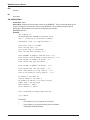
a description of the security levels). Once logged in, the screen should show the following
information.
Welcome to MultiModemManager MR4800E
version E-1.02 (OCT 24 1996 18:06:37) 10/29/1996 3:14pm
Press any key to start system manually...starting............done
Username: supervisor
Password
*********
[0] A:\ #
The command line prompt is the current directory followed by a '#' character. There are two drives
formatted on the MR4800E, A and B, and you can switch between them by using the CD command or
by typing A: or B:. A standard set of DOS and UNIX file system commands are available, albeit in
limited fashion (no wildcards are supported, etc.). See Chapter 4 for the command reference to see
how each of the commands are supported.
There are commands that allow you to monitor activity on the modems in the rack. The commands
GETMODEMS, GETCALLS, and GETFAULTS allow you to see the current state of the modems, the
connection history of the modems and the history of faults on the modems, respectively.
Information that is displayed which goes beyond the size of the screen, will be output a page at a
time using a "--MORE--" prompt. When you get this prompt, you have the option of quitting the list by
typing "Q" or continuing the list by typing anything else.
There are commands that allow you to change the current state of the modems. With the commands
OOSSET, OOSCLEAR, RESET, CONFIG, you can set modems in or out of service; reset them or
configure them, respectively.
LOGOUT should be used when you are done using the command line interface so that the MR4800E
is left in a secure state.
See Chapter 4 for a complete list of the commands that are available for use.
17
MR4800E Owner’s Manual
3.6 Telnet Interface
Telnet is an Internet standard protocol that allows the remote login between two systems connected
to a TCP/IP network (such as the Internet). The MR4800E can be managed remotely by using Telnet.
Telnet will give the user access to all management functions through the command line interface.
There is an inactivity timer associated with the Telnet session. If there is no activity for 10 minutes,
then the Telnet session will close.
3.7 Web Browser Interface
The MR4800E can be monitored/controlled from a Web browser such as Netscape Navigator version
2.0 or later or Microsoft Internet Explorer version 3.0 or later.
There are two main interfaces available: a HTML framed interface (where the browser screen is split
into Frames holding different information ) and a Non-Framed interface. To get to the framed interface
type in the following URL in your browser’s URL entry line and hit enter.
http://111.222.333.444/mmm/main.html
For the Non-Framed interface, use the following URL:
http://111.222.333.444/mmm/standard.html
where 111.222.333.444 is your card’s IP address.
3.7.1 Logging In
Whenever you access the MR4800E for first time during a browser session (since the browser
program was run), you will be prompted for a user ID and password. You must login as someone of
operator level of security or higher to get access to the Web interface.
Once logged in both interfaces present the users with a list of available views (Framed or Standard),
a list of operations, and a list of information views. These are all available via HTML hot-links.
3.7.2 Getting Modem Information
In each interface the same information is available in table format. There are tables of information
about modems, calls on modems, modem faults and system faults, and system version. In the
framed version these tables appear in each of the frames, in the non-framed version each of the
tables appear on a separate HTML page.
3.7.3 Controlling Modems
In each interface, the user can also reset modems, set in/out-of service modems, and configure
modems. When the user selects the hot-link for that operation, they are presented with a form where
they enter (in list format - e.g., 1A:3C,15B) which modems are to have the desired operation
performed on them. After entering this list, the operation is performed when the user selects the
“action” button (e.g., Config if the user is configuring modems).
3.7.4 Web Interface Limitations
The Web interface does not provide the full management interface at this point (full management is
provide either through our MultiModemManager software, or through the use of a 3rd Party SNMP
manager). Once the system is set up though, most management can be done using the Web
Browser interface.
18
Chapter 3 - Hardware Operation
3.8 FTP Interface
FTP (File Transfer Protocol) is an Internet standard protocol that allows the transfer of files between
two systems connected to a TCP/IP network (such as the Internet). The MR4800E acts as an FTP
server so that FTP clients can send/receive files from it.
FTP is necessary so that you can transfer configuration files (*.cfg) to/from your system. If you plan
to use MultiModemManager security you will need to transfer security files (*.db) to/from your
system. If you wish to analyze event information, you will need to transfer event files (*.hr) from the
MR4800E to your system where you can run the Statistical Analyzer on them.
Note:
When logging in, you must use the Supervisor user name and password.
3.9 PPP Interface
PPP (Point-to-Point Protocol) is an Internet standard protocol that allows TCP/IP connections over a
serial data link. The 9-pin serial connector on the front of the MR4800E is for a PPP connection to
the MR4800E.
19
MR4800E Owner’s Manual
20
MultiModemManager
Chapter 4 - Commands
MR4800E Owner’s Manual
4.1 Parameter Descriptions
Here is a description of the parameters used in the command descriptions that follow.
Pathname
Description: A DOS style pathname. A partial path assumes the current directory.
Example:
a:\mmm\mr4800.ini, shows a full pathname
Example:
mr4800.ini, shows a partial pathname
This partial pathname is the same as a:\mmm\mr4800.ini if the current working directory is a:\mmm.
Device
Description: A list of modems separated by commas. An inclusive list may also be used.
Example:
1A,2A:3A,4C comprises the modems (1A,2A,2B,2C,3A, and 4C)
Note:
Spaces are not allowed in the modem list.
IP Address
Description: A string of four numbers (up to 3 digits) separated by periods.
Example:
192.168.4..25
IP Address Mask
Description: An IP Address Mask is used to define a set or range of IP Addresses. It may contain
components of 255 or 0.
Example:
255.255.255.0
22
Chapter 4 - Commands
4.2 Commands Listed by Function
In this section, the commands are listed alphabetically by function. The functions are: Display,
Environment, File, Modem Control, and Security.
See Section 4.4 (Command Reference) for expanded descriptions of the commands.
Display
Command Name
Parameters
Description
getcalls
Device
Displays call traffic for the device
getfaults
Device
Displays faults for the device
getmodems
Device
Displays the current status for the device
Command Name
Parameters
Description
cl, clock
None
Displays current date and time
date
None
Prompts you for current date
getgateway
None
Display the configured gateway address
getip
None
Display the configured IP address
getreadcommunity
None
Displays the Read community settings
getsendtrap
None
Displays whether traps are being sent or not.
getsubnet
None
Display the configured subnet mask
gettrap
None
Display the configured trap address
getwritecommunity
None
Displays the Write community settings
setgateway
IP Address
Configure the gateway address
setip
IP Address
Configure the IP address
setreadcommunity
None
Change the Read community settings
setsendtrap
On/Off
Changes the status of sending traps.
setsubnet
IP Address
Mask
Configure the subnet mask
settrap
IP Address
Configured the trap address
setwritecommunity
None
Change the Write community settings
time
None
Prompts you for current time
Environment
23
MR4800E Owner’s Manual
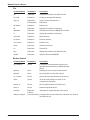
File
Command Name
Parameters
Description
cat
Pathname
Display the contents of an ASCII text file
cd, chdir
Pathname
Change to the specified directory
copy, cp
Pathname1
& Pathname2
Copy a file from Pathname1 to
Pathname2
del, delete
Pathname
Delete a file
dir
Pathname
Display the contents of a directory
download
Pathname
Download a file from the MR4800E controller
ls
Pathname
Display the contents of a directory
md, mkdir
Pathname
Make directory
rd, remdir
Pathname
Remove directory
ren, rename
Pathname
Rename a file
rendir
Pathname
Rename a directory
rm
Pathname
Delete a file
type
Pathname
Display the contents of an ASCII text file
upload
Pathname
Upload a file to the MR4800E.
Command Name
Parameters
Description
cfg, configure
Device
Configure the specified device with the configuration file associated (via SNMP) with that
device
getfkey1-
None
Displays the current value for the function
getfkey4
None
keys used when on-line with a device
oc, oosclear
Device
Set the device at specified device In Service
online
Device
Go on-line with a device to check or set
configuration information
oosset, os
Device
Set the specified device Out Of Service
reset, rs
Device
Reset the specified device
setconfig
Pathname
& Device
Associates a configuration file with a device
setfkey1-setfkey4
Command String Configures the current function key values for use when online with a device
Modem Control
24
Chapter 4 - Commands
Security
Command Name
Parameters
Description
lo, logout
None
Logs you off of the system so next user has
to login to get access
passwd, password
None
Will prompt you for old, new, and new pass
word
security
None
Allows the modification of a subordinate
security levels username and password
userid
None
Will prompt you for old, new, and new user id
whoami
None
Tells you what user is currently logged in
Command Name
Parameters
Description
boot
None
Reboot MR4800E
history
None
Display command history buffer
readme
None
Display information about most recent
changes to firmware
System
25
MR4800E Owner’s Manual
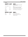
4.3 Commands Listed by Security Level
In this section, the commands are listed by security level. The security levels are: Guest, Operator,
and Supervisor.
See Section 4.4 (Command Reference) for expanded descriptions of the commands.
Guest
Command Name
Parameters
Description
cat
Pathname
Display the contents of an ASCII text file
cd, chdir
Pathname
Change to the specified directory
cl, clock
None
Displays current date and time
dir
Pathname
Display the contents of a directory
getgateway
None
Display the configured gateway address
getip
None
Display the configured IP address
getsendtrap
None
Displays whether traps are being sent or not.
getsubnet
None
Display the configured subnet mask
gettrap
None
Display the configured trap address
history
None
Display command history buffer
logout, lo
None
Logs you off of the system so next user has
to login to get access.
ls
Pathname
Display the contents of a directory
passwd, password
None
Will prompt you for old, new, and new pass
word
security
None
Allows the modification of a subordinate
security levels username and password
type
Pathname
Display the contents of an ASCII text file
userid
None
Will prompt you for old, new, and new user id
whoami
None
Tells you what user is currently logged in
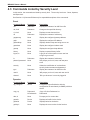
Command Name
Parameters
Description
cfg, configure
Device
Configure the specified device with the
configuration file associated (via SNMP) with that
device
copy, cp
Pathname1
Copy a file from Pathname1 to
& Pathname2
Pathname2
date, d
None
Prompts you for current date
getcalls
Device
Displays call traffic for the device
getfaults
Device
Displays faults for the device
getfkey1-
None
Displays the current value for the function
Operator
26
Chapter 4 - Commands
Operator (cont.)
Command Name
Parameters
Description
getfkey4
None
keys used when on-line with a device
getmodems
Device
Displays the current status for the device
oc, oosclear
Device
Set the device at specified device In Service
oosset, os
Device
Set the specified device Out Of Service
readme
None
Display information about most recent
changes to firmware
reset, rs
Device
Reset the specified device
setconfig
Pathname
& Device
Associates a configuration file with a device
setfkey1-
Command
Configures the current function key values for
setfkey4
String
use when on-line with a device
time
None
Prompts you for current time
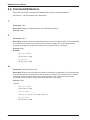
Command Name
Parameters
Description
boot
None
Reboot MR4800E
del, delete
Pathname
Delete a file
download
Pathname
Download a file from the MR4800E controller
getreadcommunity
None
Displays the Read community settings
getwritecommunity
None
Displays the Write community settings
md, mkdir
Pathname
Make directory
rd, remdir
Pathname
Remove directory
ren, rename
Pathname
Rename a file
rendir
Pathname
Rename a directory
rm
Pathname
Delete a file
setgateway
IP Address
Configure the gateway address
setip
IP Address
Configure the IP address
setreadcommunity
None
Change the Read community settings
setsendtrap
On/Off
Changes the status of sending traps.
setsubnet
IP Address
Mask
Configure the subnet mask
settrap
IP Address
Configured the trap address
setwritecommunity
None
Change the Write community settings
upload
Pathname
Upload a file to the MR4800E.
Supervisor
27
MR4800E Owner’s Manual
4.4 Command Reference
This section has all the commands listed alphabetically with an expanded explanation.
See Section 4.1 for a description of the parameters.
?
Parameters: None
Description: Displays an alphabetical list of the available commands.
Security: Guest
!!
Parameters: None
Description: Repeats the last command that has been saved in the history buffer. The command that
is executed is then placed into the history at the current command index. A list of the previously
executed commands can be printed by looking at the command history. See history.
Security: Guest
Example:
[0] A:\ # clock
10/29/1996 1:20pm
[1] A:\ # !!
10/29/1996 1:20pm
!n
Parameters: command history index.
Description: Repeats the command whose index is indicated by the parameter. The command index
is the number shown in the prompt when the command is executed. The command that is executed
is then placed into the history at the current command index. A list of the previously executed
commands can be printed by looking at the command history. See history.
Security: Guest
Example:
[0] A:\ # clock
10/29/1996 1:20pm
[1] A:\ # ver
Version E-1.02 (Oct 24 1996 18:06:37)
[2] A:\ # !0
10/29/1996 1:20pm
28
Chapter 4 - Commands
!a
Parameters: The letter (or letters) of the command to search for.
Description: Repeats the command whose beginning letter (or letters) is (are) indicated by the
parameter. The command that is executed is then placed into the history at the current command
index. A list of the previously executed commands can be printed by looking at the command history.
See history.
Security: Guest
Example:
[0] A:\ # clock
10/29/1996 1:20pm
[1] A:\ # ver
Version E-1.02 (Oct 24 1996 18:06:37)
[2] A:\ # !cl
10/29/1996 1:20pm
boot
Parameters: None
Description: Re-boots the system by performing a reset of the MR4800E controller card. A prompt is
displayed confirming your desire to re-boot the system. If you wish to re-boot the system, enter ‘y’.
Any other key will halt the re-boot operation.
Security: Supervisor
Example:
[0] A:\ # boot
Are you sure you wish to reboot the controller card?
(y/n)
cat
Parameters: Pathname
Description: Displays the contents of an ASCII text file. The cat command will display the contents
of the ASCII file referred to by pathname to the screen.
Security: Guest
Limitations: The cat command is more similar to the DOS TYPE command than it is to the UNIX cat
command.
Example:
[0] A:\MMM # cat mr4800.ini
[SecurityFile]
NumberOfFile = 1
1 = mr4800.db
[SecurityConfig]
UseridPrompt = ^m^jUserid:
PasswordPrompt = ^m^jPassword:
WelcomeMsg = ^m^jConnected to MultiModemManager System:^m^j
...
29
MR4800E Owner’s Manual
cd, chdir
Parameters: Pathname
Description: Change to the specified directory. The cd command sets the current working directory
to Pathname.
Security: Guest
Example:
[0] A:\ # cd mmm
[1] A:\MMM #
cfg, configure
Parameters: Device
Description: Configure the specified device with the configuration file associated (via SNMP) with
that device. The cfg command causes the configuration file associated with the modems specified by
Device to be sent. If the modem is connected the config commands will be ignored.
Security: Guest
Example:
[0] A:\MMM # cfg 1a,2a:2c
[1] A:\MMM #
chdir
See cd.
cl, clock
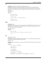
Parameters: None
Description: Displays current date and time (24 hour clock).
Security: Guest
Limitations: The time does not change automatically with daylight savings time.
Example:
[0] A:\MMM # cl
10/29/96 1:20pm
[1] A:\MMM #
configure
See cfg.
30
Chapter 4 - Commands
copy, cp
Parameters: Pathname1 & Pathname2
Description: Copy a file from Pathname1 to Pathname2. Copy the file indicated by Pathname1 to
the file indicated by Pathname2. If Pathname2 exists, it is destroyed.
Security: Operator
Example:
[0] A:\MMM # copy mr4800.ini mr4800.old
[1] A:\MMM #
d, date
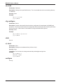
Parameters: None
Description: Prompts you for current date. The date command allows you to set the date for the
MR4800E.
Security: Operator
Example:
[0] A:\MMM # d
The current date is: 5/15/1996
Enter the new date: mm/dd/yyyy 10/29/96
[1] A:\MMM # cl
10/29/96 1:37pm
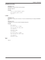
del, delete, rm
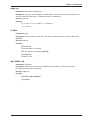
Parameters: Pathname
Description: Delete a file. Delete the file indicated by the pathname. The file is destroyed
permanently and can not be recovered.
Security: Supervisor
Example:
[0] A:\MMM # del mr4800.old
[1] A:\MMM #
31
MR4800E Owner’s Manual
dir, ls
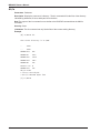
Parameters: Pathname
Description: Display the contents of a directory. The dir command will list the files of the directory
indicated by pathname, file size, and bytes left on the drive.
Note:The output of the ls command is more similar to the DOS DIR command than the UNIX ls
command.
Security: Guest
Limitations: The dir command can only list the files of the current working directory.
Example:
[0] A:\MMM # dir
The current directory is 'A:\MMM'
..
<DIR>
...
<DIR>
MR4800.INI
965
MR4800.GP
4155
MR4800.CNF
12221
MR4800.INV
3812
MR4800.DB
792
DEFAULT.CFG
0
MR4800.SAV
192
MR.LOG <DIR>
7 file(s) 22137 bytes
3 dirs(s) 1015296 bytes free
[1] A:\MMM #
32
Chapter 4 - Commands
download
Parameters: Pathname
Description: Download a file from the MR4800E. The download command will allow you to move
files off of the MR4800E to another location. The files are output as the hexadecimal values
surrounded by square brackets.
Note:
Files will normally be transferred off of the system using FTP.
Security: Supervisor
Limitations: This does not respond to flow control.
Example:
[0] A:\MMM # download mr4800.old
[5b][46][61][75][6c][74][41][6c][61][72][6d][73][5d][0d][0a][43]
[61][72][64][20][49][6e][73][74][61][6c][6c][65][64][20][3d][20]
[4f][4e][2c][30][2c][4e][4f][4e][45][0d][0a][43][61][72][64][20]
[52][65][6d][6f][76][65][64][20][3d][20][4f][4e][2c][30][2c][4e]
[4f][4e][45][0d][0a][50][6f][77][65][72][20][53][75][70][70][6c]
[79][20][46][61][69][6c][75][72][65][20][3d][20][4f][4e][2c][30]
[2c][4e][4f][4e][45][0d][0a][44][69][73][63][6f][6e][6e][65][63]
[74][3a][20][50][6f][77][65][72][4f][6e][20][6f][72][20][57][61]
[74][63][68][44][6f][67][20][3d][20][4f][4e][2c][30][2c][4f][4f]
...
[1] A:\MMM #
33
MR4800E Owner’s Manual
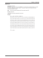
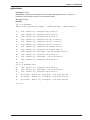
getcalls
Parameters: Device
Description: Displays call traffic for Device. If there is no parameter, call traffic is listed for every
installed modem.
Security: Supervisor
Example:
[0] A:\ #
[1] A:\ # getcalls
Modem DateTime
Call Duration
User ID Phone Number
1A
No Calls
1B
No Calls
1C
05-21 08:15:02
A-33600-V.42bis
000-00:00:08
1C
05-21 08:15:41
A-33600-V.42bis
000-00:00:08
1C
05-21 08:32:58
A-33600-V.42bis
000-00:00:09
2A
05-21 08:13:48
O-33600-V.42bis
000-00:00:08
DT13
2A
05-21 08:14:26
O-33600-V.42bis
000-00:00:09
DT13
2A
05-21 08:15:02
O-33600-V.42bis
000-00:00:08
DT13
2A
05-21 08:16:20
O-33600-V.42bis
000-00:00:08
DT13
2A
05-21 08:33:02
Originate
2B
05-21 08:13:47
O-33600-V.42bis
...
[2] A:\ #
34
Connect Info.
Open Call
000-00:00:08
DT13
DT16
Chapter 4 - Commands
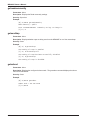
getfaults
Parameters: Device. If there is no parameter, then system faults are listed.
Description: Displays faults for Device. If there is no parameter, faults are listed for every installed
modem.
Security: Operator
Example:
[0] A:\
# getfaults
Modem Date
1
Time
Fault Description
06-05 10:18:51
Rack Online
06-05 10:19:17
Remote management session initiated
11
06-05 10:19:26
Modem card Removed
7
06-05 10:19:31
Modem card Removed
8
06-05 10:19:46
Modem card Installed
[1] A:\ #
[2] A:\ # getfaults 3a:3c
3A
3B
No fault/status found
05-21 08:27:1
3C
Modem reset by rack controller card
No fault/status found
[3] A:\ #
35
MR4800E Owner’s Manual
getfkey1, getfkey2, getfkey3, getfkey4
Parameters: None
Description: Displays the current configure values for the on-line function keys. These function
keys are available for use when one is on-line with a modem. See online.
Security: Operator
Example:
[0] A:\ # getfkey1
Function Key 1: 'ATL5'
[1] A:\ # getfkey2
Function Key 2: 'ATL6'
[2] A:\ # getfkey3
Function Key 3: 'ATL5L6L7'
[3] A:\ # getfkey4
Function Key 4: 'ATI1I2I3I4'
getgateway
Parameters: None
Description: Displays the configured gateway address. The getgateway command displays the
default gateway IP address (if one is set) for the MR4800E.
Security: Guest
Example:
[0] A:\MMM # getgateway
Gateway IP Address = 199.199.99.1
[1] A:\MMM #
getip
Parameters: None
Description: Displays the configured IP address. The getip command displays the IP address
of the MR4800E.
Security: Guest
Example:
[0] A:\MMM # getip
IP Address = 199.199.99.9
[1] A:\MMM #
36
Chapter 4 - Commands
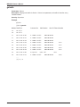
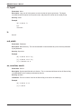
getmodems
Parameters: Device
Description: Displays the current status for the modems indicated by Device. If there is no
parameter, current status is listed for every installed modem.
Security: Operator
Example:
[0] A:\ # getmodems
Modem Current State Config Filename
Modem Group Name
1A
Idle
default.cfg
Group1 Dial Up No Security
1B
Idle
default.cfg
Group1 Dial Up No Security
1C
Idle
default.cfg
Group1 Dial Up No Security
2A
Idle
default.cfg
Group1 Dial Up Call In Security
2B
Dial
default.cfg
Group1 Dial Up Call In Security
2C
Ring
default.cfg
Group1 Dial Up Call In Security
3A
Dial
default.cfg
Group1 Dial Up Callback Security
3B
Ring
default.cfg
Group1 Dial Up Callback Security
3C
Idle
default.cfg
Unassigned
4A
Idle
default.cfg
Group1 Dial Up No Security
4B
Idle
default.cfg
Unassigned
4C
Idle
default.cfg
Group1 Dial Up No Security
Modem Inventory
Dial Up Callback Security
Dial Up No Security
[1] A:\ #
[2] A:\ # getmodems 4a:5c
4A
Idle
default.cfg
Group1 Dial Up No Security
4B
Idle
default.cfg
Unassigned
4C
Idle
default.cfg
Group1 Dial Up No Security
5A
Not Present
default.cfg
Unassigned
Dial Up No Security
5B
Not Present
default.cfg
Unassigned
Dial Up No Security
5C
Not Present
default.cfg
Unassigned
Dial Up No Security
Dial Up No Security
[3] A:\ #
37
MR4800E Owner’s Manual
getreadcommunity
Parameters: None
Description: Displays the Read community settings.
Security: Supervisor
Example:
[0] A:\MMM # getreadcommunity
Read community = public
Enter SETREADCOMMUNITY <community-string> to change it.
[1] A:\ #
getsendtrap
Parameters: None
Description: Displays whether traps are being sent from the MR4800E or not. See setsendtrap.
Security: Guest
Example:
[0] A:\ # getsendtrap
The sending of traps is enabled.
[1] A:\ # setsendtrap off
The sending of traps has been successfully disabled.
[2] A:\ # getsendtrap
The sending of traps is disabled.
getsubnet
Parameters: None
Description: Displays the configured subnet mask. The getsubnet command displays the subnet
mask for the MR4800E.
Security: Guest
Example:
[0] A:\MMM # getsubnet
Subnet mask = 255.255.255.0
[1] A:\MMM #
38
Chapter 4 - Commands
gettrap
Parameters: None
Description: Display the configured trap address. The gettrap command displays the default trap IP
address (if one is set) for the MR4800E. This is the address to which the MR4800E generated traps
(i.e. fault/status traps) are sent.
Security: Guest
Example:
[0] A:\MMM # gettrap
Trap IP Address = 199.199.99.91
[1] A:\MMM #
getwritecommunity
Parameters: None
Description: Displays the Write community settings.
Security: Supervisor
Example:
[0] A:\MMM # getwritecommunity
Write community = public
Enter SETWRITECOMMUNITY <community-string> to change it.
[1] A:\MMM #
history
Parameters: None
Description: Displays the command history buffer.
Security: Guest
Example:
[4] A:\ # history
0
VER
1
CLOCK
2
VER
3
CLOCK
4
HISTORY
[5] A:\ #
39
MR4800E Owner’s Manual
lo, logout
Parameters: None
Description: Logs you off of the system so next user has to login to get access. The logout
command ends the session for the previous user, and places the monitor at the userid prompt.
Security: Guest
Example:
[0] A:\MMM # lo
Bye.
UserName:
ls
See dir.
md, mkdir
Parameters: Pathname
Description: Make directory. The md command will create a subdirectory in the directory indicated
by the pathname.
Security: Supervisor
Example:
[0] A:\MMM # md mr.log
[1] A:\MMM # cd mr.log
[2] A:\MMM\MR.LOG #
oc, oosclear, oosclr
Parameters: Device
Description: Set the specified device In Service. The oc command will clear the Out Of Service flag
in the MR4800E for the modem(s) indicated by Device.
Security: Operator
Limitations: There is no effect if the Out Of Service flag is not set for the modem(s).
Example:
[0] A:\MMM # oc 1a
[1] A:\MMM #
40
Chapter 4 - Commands
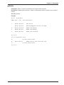
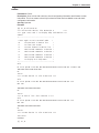
online
Parameters: Device
Description: Goes on-line with a device to check configuration information and firmware version
information. This is not meant to be a fully functional terminal. But is available to set and check
configuration information.
Security: Operator
Example:
[0] A:\ # online 6a:6c
==== Online with device: Slot 06 Device A
====
==== type <esc> and ? to display help information ====
<esc>?
+---------------------------------------+
! <esc> again to exit terminal mode
!
! b
to move back in device list
!
! c
to clear the screen
!
! n
to move forward in device list
!
! 1
send stored command 1 to device !
! 2
send stored command 2 to device !
! 3
send stored command 3 to device !
! 4
send stored command 4 to device !
! ?
to display this help menu
!
+---------------------------------------+
atl5
B1 E1 M1 Q0 R0 V1 X4 &E1 &E4 &E6 &E8 &E10 &E13 &E15 %C0 #C1 *C0 &C1 *H0
$MB33600 $SB115200 $BA0 &W1
OK
<esc>n
==== Current device is: Slot 6 Device B ====
atl5
B1 E1 M1 Q0 R0 V1 X4 &E1 &E4 &E6 &E8 &E10 &E13 &E15 %C0 #C1 *C0
&C1 *H0
$MB28800 $SB57600 $BA0 &W1
OK
<esc>n
==== At end of list: Slot 6 Device C ====
atl5
B1 E1 M1 Q0 R0 V1 X4 &E1 &E4 &E6 &E8 &E10 &E13 &E15 %C0 #C1 *C0
&C1 *H0
$MB28800 $SB57600 $BA0 &W1
OK
<esc>b
==== Current device is: Slot 6 Device B ====
<esc><esc>
Goodbye!
[1] A:\ #
41
MR4800E Owner’s Manual
oosset, os
Parameters: Device
Description: Set the specified device Out of Service. The os command will set the Out Of Service
flag in the MR4800E for the modem(s) indicated by Device.
Security: Operator
Limitations: If the modem(s) are connected, they will remain off hook when the call is completed.
Example:
[0] A:\MMM # os 1a
[1] A:\MMM #
passwd, password
Parameters: None
Description: Will prompt you for old, new, and new password. The passwd command will allow you
to change your password by prompting you for the current password and new password.
Security: Guest
Example:
[0] A:\MMM # passwd
Current password: *****
New password: *****
Repeat new password: *****
Security information updated
[1] A:\MMM #
readme
Parameters: None
Description: Displays a summary listing of the most recent modifications made to the firmware for
the MR4800E.
Security: Operator
Example:
[0] A:\ # readme
MR4800E version 1.02 release information
-- 1. Web Server functionality -------. . .
-- 2. MR4800E MIB -------. . .
-- 3. Known Limitations -------. . .
[1] A:\ #
42
Chapter 4 - Commands
rd, remdir
Parameters: Pathname
Description: Remove directory. The rd command will delete the directory indicated by the
pathname.
Security: Supervisor
Limitations: The directory must be empty before rd will successfully delete it. You are not given the
option of deleting a directory and it’s subdirectories.
Example:
[0] A:\MMM # rd mr.log
[1] A:\MMM #
ren, rename
Parameters: Pathname Pathname
Description: Rename a file. The ren command will change the name of the file indicated by
pathname.
Security: Supervisor
Example:
[0] A:\ # ren temp.txt temp1.txt
[1] A:\ #
rendir
Parameters: Pathname
Description: Rename a directory. The rendir command will change the name of the directory
indicated by the pathname.
Security: Supervisor
Example:
[0] A:\ # rendir MMM MMM1
[1] A:\ #
reset, rs
Parameters: Device
Description: Reset the specified device. The reset command will cause the modem(s) indicated by
the device to cycle power. This will cause any modem(s) that are connected to disconnect.
Security: Operator
Example:
[0] A:\ # reset 1a
[1] A:\ #
43
MR4800E Owner’s Manual
rm
See del.
rs
See reset.
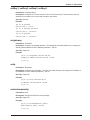
se, setenviron
Parameters: None
Description: Change the environment values for the MR4800E. The se command allows you to
check or change the environment values for the MR4800E. The IP Address, default Trap IP,
Gateway IP, Subnet Mask, and community strings may be changed.
Security:Supervisor
Example:
[0] A:\MMM # se
MultiModemManager MR4800E Environment setup
Use '-' to back up to the previous command.
The default value is in angle brackets <>.
The current time is: 11:04pm
Enter the new time: <cr>1
The current date is: 10/30/1996
Enter the new date: mm/dd/yy <cr>1
Enter MR4800E IP Address <199.199.99.9>: <cr>1
Enter Default Trap IP Address <199.199.99.91>: <cr>1
Enter Gateway IP Address <0.0.0.0>: <cr>1
Enter Subnet Mask <255.255.255.0>: -2
Enter Gateway IP Address <0.0.0.0> : <cr>1
Enter Subnet Mask <255.255.255.0> : <cr>1
Enter read community string <public> : <cr>1
Enter write community string <public> : <cr>1
IP Address = 192.168.4.44
Trap IP Address = 192.168.4.6
No gateway IP address is currently stored.
Subnet mask = 255.255.255.0
Read community = public
Write community = public
Enter SETENVIRON to change these settings
[1] A:\MMM #
Foot Notes:
1
Press Enter (<cr>) to accept the current value.
2
Press hyphen (-) to go back to the previous command.
3
Entered an invalid IP Address.
44
Chapter 4 - Commands
security
Parameters: None
Description: Allows the modification of a subordinate security levels username and password. The
security command allows you to change the user id and password for any security levels lower than
yours.
Security: Supervisor
Example:
[0] A:\MMM # security
Modify security information for which security level:
1. Guest level
2. Operator level
3. Supervisor level
Which one? 1
Enter User ID : guest
Enter new password : *****
Repeat new password : *****
Security information updated
[1] A:\MMM #
45
MR4800E Owner’s Manual
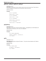
setconfig
Parameters: Pathname & Device
Description: Associates a configuration file with a particular device.
Security: Operator
Example:
[0] A:\ # getmodems
2A
Idle
default.cfg
Unassigned
Dial Up No Security
2B
Idle
default.cfg
Unassigned
Dial Up No Security
2C
Idle
default.cfg
Unassigned
Dial Up No Security
4A
Idle
default.cfg
Unassigned
Dial Up No Security
4B
Idle
default.cfg
Unassigned
Dial Up No Security
4C
Idle
default.cfg
Unassigned
Dial Up No Security
[1] A:\ # setconfig unix.cfg 2a:2c
[2] A:\ # setconfig rsa.cfg 4a:4c
[3] A:\ # getmodems
46
2A
Idle
unix.cfg
Unassigned
Dial Up No Security
2B
Idle
unix.cfg
Unassigned
Dial Up No Security
2C
Idle
unix.cfg
Unassigned
Dial Up No Security
4A
Idle
rsa.cfg
Unassigned
Dial Up No Security
4B Idle
rsa.cfg
Unassigned
Dial Up No Security
4C
rsa.cfg
Unassigned
Dial Up No Security
Idle
Chapter 4 - Commands
setfkey1, setfkey2, setfkey3, setfkey4
Parameters: Command String
Description: Configures the current values for the on-line function keys. These function keys are
available for use when one is on-line with a modem. See online.
Security: Operator
Example:
[0] A:\ # getfkey1
Function Key 1: "ATL5"
[1] A:\ # setfkey1 ATL5L6L7
Function Key 1: "ATL5L6L7"
[2] A:\ # getfkey1
Function Key 1: "ATL5L6L7"
setgateway
Parameters: IP Address
Description: Configure the gateway address. The setgateway command allows you to change the
default gateway address to the IP Address parameter. See se.
Security: Supervisor
Example:
[0] A:\ # setgateway 199.199.199.191
Gateway IP Address 199.199.199.191 stored
[1] A:\ #
setip
Parameters: IP Address
Description: Configure the IP address. The setip command allows you to change the IP address of
the MR4800E to the IP Address parameter. See se.
Security: Supervisor
Example:
[0] A:\ # setip 199.199.199.44
IP Address 199.199.199.44 stored
[1] A:\ #
setreadcommunity
Parameters: None
Description: Change the Read community settings.
Security: Supervisor
Example:
[0] A:\ # setreadcommunity public
Read Community public stored
[1] A:\ #
47
MR4800E Owner’s Manual
setsendtrap
Parameters: on, off
Description: Configure the MR4800E controller card to send traps or not. This command can be
used to disable the sending of traps from a controller card to a SNMP manager or
MultiModemManager console.
Security: Supervisor
Example:
[0] A:\ # getsendtrap
The sending of traps is enabled.
[1] A:\ # setsendtrap off
The sending of traps has been successfully disabled.
[2] A:\ # getsendtrap
The sending of traps is disabled.
setsubnet
Parameters: IP Address Mask
Description: Configure the subnet mask. The setsubnet command allows you to change the subnet
mask to the IP Address parameter. See se.
Security: Supervisor
Example:
[0] A:\ # setsubnet 255.255.255.0
Subnet mask 255.255.255.0 stored
[1] A:\ #
settrap
Parameters: IP Address
Description: Configure the trap address. The settrap command allows you to change the default
trap IP Address to the IP Address parameter. This IP is where fault/status traps are sent. See se.
Security: Supervisor
Limitations: Only one default trap address may be set at one time.
Example:
[0] A:\ # settrap 199.199.199.6
Trap IP Address 199.199.199.6 stored
[1] A:\ #
48
Chapter 4 - Commands
setwritecommunity
Parameters: None
Description: Change the Write community settings.
Security: Supervisor
Example:
[0] A:\ # setwritecommunity public
Write Community public stored
[1] A:\ #
t, time
Parameters: None
Description: Prompts you for current time. The time command allows you to change the MR4800E
time.
Security: Operator
Limitations: The time is not corrected for daylight savings time.
Example:
[0] A:\MMM # t
The current time is: 4:59pm
Enter the new time: hh:mm 17:10
[1] A:\MMM # cl
10/30/1996 5:10pm
[2] A:\MMM # t
The current time is: 5:10pm
Enter the new time: hh:mm 5:12pm
[3] A:\MMM # cl
10/30/1996 5:12pm
type
See cat.
49
MR4800E Owner’s Manual
update
Parameters: [Pathname {Device}]
Description: Updates the controller and modem firmware. The update command allows you to flash
firmware into both the controller and the modems. Controller firmware must end with a .HXC
extension. Modem firmware must end with a .HEX extension. The firmware files must reside on the
A:\ or B:\ drives of the controller. Update by itself views modem progress.
Note:
Files will normally be transferred to the system using FTP.
Security: Supervisor
Limitations: Controller firmware must be stored on the B:\ drive because of the file size.
Example:
[3] update 28mr114.hex
Update
2a:2c
Started
[4] A:\MMM # update
Percent Done = 59%
`
2a
Updating
2b
Updating
2c
Updating
[14] B:\MMM # update rel312.hxc
Percent Done = 68%
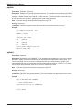
upload
Parameters: Pathname
Description: Upload a file to the MR4800E. The upload command allows you to move a file onto the
MR4800E. Binary files can be uploaded by first converting them to ASCII on the host system. The
format for the data is one or more lines of hexadecimal data up to 80 characters in length, where
each hexadecimal value is surrounded by a left and right square bracket (e.g., [2b][3c]...[1c]). When
the file is done being uploaded, press Esc or Ctrl-D to complete the upload.
Note:
Files will normally be transferred to the system using FTP.
Security: Supervisor
Limitations: Only ASCII files can be uploaded. This command does not support flow control, so the
files should be uploaded using an ASCII file transfer with a 1 millisecond delay between lines.
Example:
[0] A:\MMM # upload mr4800.db
...data uploaded here...
2192 byte(s) written to 'mr4800.db'
[1] A:\MMM #
50
Chapter 4 - Commands
userid
Parameters:None
Description: Will prompt you for old, new, and new user id. The userid command allows you to
change your userid by prompting you for your current and new userid.
Security: Guest
Example:
[0] A:\MMM # userid
Current user id: super
New user id: supervisor
Security information updated
[1] A:\MMM #
ver, version
Parameters: None
Description: Display the current version of the MR4800E.
Security: Guest
Example:
[0] A:\MMM # ver
Version E-1.02 (Oct 24 1996 18:06:37)
[1] A:\MMM #
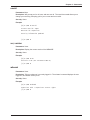
whoami
Parameters: None
Description: Tells you what user is currently logged in. The whoami command displays the user
logged on, and his/her security level.
Security: Guest
Example:
[0] A:\MMM # whoami
supervisor with < supervisor> access rights
[1] A:\MMM #
51
MR4800E Owner’s Manual
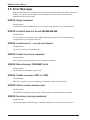
4.5 Error Messages
When you receive an error message when executing a command be sure to check the command
spelling. Do you have access rights to the command? Do you have the correct number of
parameters in the correct format?
ERROR: Illegal command
Possible Cause:
The command may be spelled wrong, or you have the wrong number or incorrect parameters.
ERROR: Invalid IP address, format ###.###.###.###
Possible Cause:
The IP address is not 4 groups of up to 3 digits separated by a period. The IP Address has no
components with a value greater than 255.
ERROR: Invalid user id — user id not changed
Possible Cause:
The user id contains an invalid character.
ERROR: Unable to perform command
Possible Cause:
User does not have the security access to execute the command.
ERROR: Make directory ‘DIRNAME’ failed.
Possible Cause:
The subdirectory ‘DIRNAME’ already exists.
ERROR: Unable to rename ‘DIR1’ to ‘DIR2’
Possible Cause:
DIR1 does not exist, or you are attempting to rename the current working directory.
ERROR: Online session already exists
Possible Cause:
The ONLINE command is active by either a Telnet session or terminal attached to CC4800.
ERROR: No history is being maintained
Possible Cause:
The command history buffer is empty or not being maintained by the command line interface.
52
Chapter 4 - Commands
ERROR: Password not changed
Possible Cause:
The old password does not match the stored password; the new password is invalid; or the new
password and the repeated new password do not match.
ERROR: Unknown error
Possible Cause:
While attempting to parse a command line an error of unknown origin occurred.
ERROR: Bad or missing configuration file
Possible Cause:
The specified configuration file is not present on the system. It is possible that the file name is
incorrectly spelled.
ERROR: Invalid number
Possible Cause:
The specified number is not a valid hex number starting with a ‘$’ or a valid decimal number starting
with a digit.
ERROR: Invalid device specifier
Possible Cause:
The device specifier is invalid since it is not of the format ‘1a’, where ‘1’ represents the slot number
for the device and ‘a’ represents the device number. See Parameter Descriptions.
ERROR: Invalid drive specifier
Possible Cause:
The specified drive letter does not indicate a drive avaliable to the system.
ERROR: Security information not changed
Possible Cause:
The new user id is invalid. The new password is invalid; or the new password and the repeated new
password do not match.
ERROR: Unable to update security information
Possible Cause:
The CMOS write error failed when updating the security information.
53
MR4800E Owner’s Manual
54
MultiModemManager
Chapter 5 - Troubleshooting
MR4800E Owner’s Manual
5.1 Introduction
This chapter provides the information needed to identify and fix problems with the MR4800E.
Problems can be observed at the MR4800E front panel (LEDs), or the dedicated management
console's PC screen. In addition, problems can be found when performing the Diagnostic Tests,
documented in Chapter 8 of the MultiModemManager Owner’s Manual.
For specific MultiModem troubleshooting information, refer to the MultiModem Owner’s Manual
shipped with your MultiModem. For basic Windows messages, refer to your Windows documentation
or Help screens.
5.2 LED Indicators
The MR4800E front panel has the following indicators.
•
MR4800E two-color LEDs (1-16)
•
Ethernet status LEDs (1-4)
5.3 Front Panel Indicators
There are 16 two-color LEDs on the front panel of the MR4800E. The LEDs indicate the state of the
installed modem cards in each of the CC4800 rack's 16 slots. On power up the lights go through a
defined sequence of events before they act as status indicators for the modem cards. This sequence
is defined below:
1.
The LEDs on the right side turn red and then turn green when the right SIMM passes it's
memory test.
2.
The LEDs on the left side turn red and then turn green when the left SIMM passes it's
memory test.
3.
The LEDs stay green for about five seconds while the flash boot code waits for a handshake
sequence on the diagnostic serial port.
4.
If none is detected (this is normal unless the firmware is being updated through the
diagnostic port) the main controller code starts running and the LEDs are turned off.
5.
The LEDs are turned on and off, one at a time, red and green.
6.
All LEDs turn green while the system starts up.
7.
When the system has started, the LEDs reflect the status of the modem cards.
After the system has started, each LED will be in the following state based on the status of the
modem card.
LED Color
Modem Card Status
Off
Card not installed
Green
Card installed and all modems are communicating with the MR4800E
Red
Card installed and none of the modems are communicating with the MR4800E
Flashing Red/Green Card installed and one or two modems are not communicating with the
MR4800E
56
Chapter 5 - Troubleshooting
5.4 Ethernet Status LEDs
The MR4800E front panel contains four Ethernet status LEDs. Each LED is described below.
LED
Color
Status
Link Integrity (LI)
yellow
on during good link
Collision Sense (CS)
red
on when there's a collision on Ethernet
Transmit (TX)
green
on during Ethernet transmit
Receive (RX)
green
on during Ethernet receive
5.5 MR4800E Diagnostic Tests
If you suspect that your MR4800E is not functioning properly, you may run the following diagnostic
tests to test the MR4800E's hardware capabilities.
1.
Put test jumper (refer to page 2-1 of the owners manual to locate the test jumper on the
controller card) into loopback position (so the two pins are shorted together). Plug the
10base-T loopback jumper into the front Ethernet connector of the MR4800E card.
2.
Use MultiExpress (or any data comm package) running at 115,200 with no flow control.
Connect the COM Port associated with the data comm package to the RS-232 port on the
back of the CC4800 rack.
3.
Reset the MR4800E by pressing the reset button on the front with a paper clip or power the
CC4800 rack off and on.
4.
When prompted to start manually, press a key.
5.
You will be prompted to enter a username and password. Login as supervisor.
6.
Type in the command HDTEST and press Enter.
7.
You will see a menu. Proceed with testing in the following order:
WARNING: Running options either out of order or ones not specified may cause
unpredictable results.
Test 2
Test 3
Test 4
Test 5
Test 7
Red LED’s on
Green LED’s on
All LED’s off
Flash memory test
Ethernet loopback test
Watch for the green Ethernet LED on left side of the Ethernet connector, it should be on
solid. Numbers stopped and packets received will match.
Test 1 Start backplane LED’s on the front of the MR4800E will reflect the
number of cards installed.
Test a Sets slot 1 modems to 9600 bps
Test b Sets slot 1 modems OOS
Test c Clears slot 1 modems OOS
Test d Resets slot 1 modems
57
MR4800E Owner’s Manual
58
MultiModemManager
Chapter 6 - Service, Warranty, & Tech Support
MR4800E Owner’s Manual
6.1 Service
In the event that repair service is required, you may send your modem to our Mounds View factory in
the USA. Products requiring repair and are shipped to us from outside the USA must have a
Returned Materials Authorization (RMA) and shipping instructions. To return products for repair from
inside the USA, no RMA is required, simply send products to us freight prepaid. Include a description
of the problem, a return shipping address, and a check or purchase order for out-of-warranty repairs.
Please send products which require repairs to the following address:
Multi-Tech Systems, Inc.
2205 Woodale Drive
Mounds View, MN 55112
Attn: Repair
If you are shipping products from outside the USA, please contact our Repair Department prior to
your shipment for an RMA. You may contact us by telephone or fax at the following numbers:
Telephone: +(612) 785-3500
Fax: +(612) 785-9874
6.2 Limited Warranty
Multi-Tech Systems, Inc. (“MTS”) warrants that its products will be free from defects in material or
workmanship for a period of two years from the date of purchase, or if date of purchase is not
provided, two years from date of shipment. MTS MAKES NO OTHER WARRANTY, EXPRESS OR
IMPLIED, AND ALL IMPLIED WARRANTIES OF MERCHANTABILITY AND FITNESS FOR A
PARTICULAR PURPOSE ARE HEREBY DISCLAIMED.
This warranty does not apply to any products which have been damaged by lightning storms, water,
or power surges or which have been neglected, altered, abused, used for purposes other than the
one which they were manufactured, repaired by the customer or any party without MTS’s written
authorization, or used in any manner inconsistent with MTS’s instructions.
MTS’s entire obligation under this warranty shall be limited (at MTS’s option) to repair or replacement
of any products which prove to be defective within the warranty period, or, at MTS’s option, issuance
of a refund of the purchase price. Defective products must be returned by Customer to MTS’s factory
transportation prepaid.
MTS WILL NOT BE LIABLE FOR CONSEQUENTIAL DAMAGES AND UNDER NO
CIRCUMSTANCES WILL ITS LIABILITY EXCEED THE PURCHASE PRICE FOR DEFECTIVE
PRODUCTS.
60
Chapter 6 - Service, Warranty & Tech Support
6.3 The Multi-Tech BBS
For customers who do not have Internet access, Multi-Tech maintains a bulletin board system (BBS)
that mirrors its FTP site. Information available from the BBS includes new product information,
product upgrade files, and problem-solving tips. The phone number for the Multi-Tech BBS is (800)
392-2432 (USA and Canada) or (612) 785-3702 (international and local).
The BBS can be accessed by any asynchronous modem operating at 1200 bps to 33,600 bps at a
setting of 8 bits, no parity, and 1 stop bit (8-N-1).
To log on to the Multi-Tech BBS
1.
2.
3.
4.
Set your communications program to 8-N-1.
Dial our BBS at (800) 392-2432 (USA and Canada) or (612) 785-3702 (international and
local).
At the prompts, type your first name, last name, and password; then press ENTER. If you are
a first time caller, the BBS asks if your name is spelled correctly. If you answer yes, a
questionnaire appears. You must complete the questionnaire to use the BBS on your first
call.
Press ENTER until the Main Menu appears. From the Main Menu you have access to two
areas: the Files Menu and News. For help on menu commands, type ?.
To Download a file
If you know the file name
1.
From the Main Menu, type F to access the Files Menu, then type D.
2.
Enter the name of the file you wish to download from the BBS.
3.
If a password is required, enter the password.
4.
Answer Y or N to the automatic logoff question.
5.
Select a file transfer protocol by typing the indicated letter, such as Z for Zmodem (the
recommended protocol).
6.
If you select Zmodem, the transfer will begin automatically. If you select another protocol, you
may have to initiate the transfer yourself. (In most datacomm programs, the PAGE DOWN
key initiates the download.)
7.
When the download is complete, press ENTER to return to the File Menu.
8.
To exit the BBS, type G and press ENTER.
If you don’t know the file name
1.
From the Main Menu, type F to access the Files Menu. For a list of file areas, type L, press
ENTER, then type L and press ENTER again. (If you do not type the second L, you will list all
of the files on the BBS.)
2.
Mark each file area you would like to examine by typing its list number and pressing ENTER.
3.
Enter L to list all the files in the selected file areas. Enter C to go forward in the file list and P
to go back.
4.
To mark one or more files for download, type M, press ENTER, type the list numbers of the
files, and press ENTER again.
5.
Enter D. You will see a list of the files you have marked. Enter E if you would like to edit the
list; otherwise enter D again to start the download process.
6.
Select a file transfer protocol by typing the indicated letter, such as Z for Zmodem (the
recommended protocol).
7.
If you select Zmodem, the file will transfer automatically. If you select another protocol, you
may have to initiate the transfer yourself. (In most data communications programs, the PAGE
DOWN key initiates the download.)
8.
When the download is complete, press ENTER to return to the File Menu.
9.
To exit the BBS, type G and press ENTER.
61
MR4800E Owner’s Manual
6.4 On-Line Upgrade via Flash PEROM and FLASHPRO
Software
The MR4800E Rack Controller has a Flash PEROM (Programmable and Erasable Read Only
Memory) chip which contains firmware code. At various times, Multi-Tech will add enhancements
and/or fixes to the firmware. The Flash technology used allows these firmware upgrades to be loaded
directly into the PEROM via the MR4800E Controller’s back configuration port connection. The
FLASHPRO software is used to reprogram the Flash PEROM using an Intel .HEX file.
This program requires:
62
•
MS-DOS version 2.11 or higher,
•
serial port on dedicated management console,
•
384K RAM available, and
•
Multi-Tech supplied INTEL .HEX file to load.
Index
Index
Symbols
!! ............................................................................ 28
!a ........................................................................... 29
10Base-T connector ................................................ 7
9 pin connector ...................................................... 11
9-pin serial connector ............................................ 19
B
BBS ....................................................................... 61
C
Cabling, Ethernet................................................... 11
Cabling, Serial ....................................................... 11
cat ......................................................................... 29
CC4800 .......................................................... 11, 12
cd .......................................................................... 30
cfg ......................................................................... 30
chdir ...................................................................... 30
cl ............................................................................ 30
clock ...................................................................... 30
Command Line Interface ....................................... 17
Command Reference ............................................ 28
Commands ............................................................ 23
community strings ................................................. 12
configuration files .................................................. 13
Configuration Manager .......................................... 13
Configuration, supervisor console ......................... 13
configure ............................................................... 30
copy ....................................................................... 31
cp .......................................................................... 31
D
d ............................................................................ 31
date ....................................................................... 31
default passwords ................................................. 16
default userids ....................................................... 16
delete .................................................................... 31
Device ................................................................... 22
diagnostic serial connector .................................... 17
Diagnostic Tests .................................................... 57
Dimensions ............................................................. 7
dir .......................................................................... 32
Display .................................................................. 23
E
Environment .......................................................... 23
Error Messages ..................................................... 52
Ethernet 10Base-T connector ................................. 7
Ethernet cable ....................................................... 12
Ethernet Cabling .................................................... 11
Ethernet connector ................................................ 12
Event Files ............................................................ 16
F
File ........................................................................ 23
File System ........................................................... 16
Front Panel Indicators ........................................... 56
FTP ................................................................ 13, 16
FTP Interface ........................................................ 19
G
gateway IP address ............................................... 12
getfaults ................................................................. 35
getfkey1 ................................................................. 36
getfkey2 ................................................................. 36
getfkey3 ................................................................. 36
getfkey4 ................................................................. 36
getgateway ............................................................ 36
getip ...................................................................... 36
getreadcommunity ...................... 28, 29, 37, 38, 39
getsendtrap ........................................................... 38
getsubnet .............................................................. 38
getwritecommunity ................................................ 39
Guest ..................................................................... 26
guest ..................................................................... 16
H
Hardware Installation ............................................. 11
HTML framed interface .......................................... 18
I
Indicators ............................................................... 56
Installation ............................................................. 11
IP Address ............................................................. 22
IP address ............................................................. 12
IP Address Mask ................................................... 22
L
LEDs ................................................................ 7, 56
lo ........................................................................... 40
logout .................................................................... 40
ls ..................................................................... 32, 40
M
md ......................................................................... 40
microprocessor ........................................................ 7
mkdir ..................................................................... 40
Modem Control ...................................................... 24
modem groups ...................................................... 13
modem inventory ................................................... 13
Motorola MC68360 .................................................. 7
MR4800 ................................................................. 11
MultiExpress ................................................... 12, 57
N
Newt TCP/IP ......................................................... 12
63
MR4800E Owner’s Manual
O
oc .......................................................................... 40
oosclear ................................................................. 40
oosclr ..................................................................... 40
oosset .................................................................... 42
Operator ................................................................ 26
operator ................................................................. 16
os .......................................................................... 42
P
Parameter Descriptions ......................................... 22
passwd .................................................................. 42
password ........................................................ 12, 42
passwords, default ................................................ 16
Pathname .............................................................. 22
Power ...................................................................... 7
power switch ......................................................... 11
PPP .................................................................. 7, 11
PPP Interface ........................................................ 19
processor ................................................................ 7
PS4800 ................................................................. 11
R
rack ................................................................ 11, 12
RAM ........................................................................ 7
rd ........................................................................... 43
readme .................................................................. 42
remdir .................................................................... 43
rename .................................................................. 43
rendir ..................................................................... 43
reset ...................................................................... 43
Reset Button ......................................................... 12
reset button ............................................... 7, 12, 57
RJ45 ................................................................. 7, 11
rm ................................................................... 31, 44
rs .................................................................... 43, 44
RS232 ............................................................ 11, 12
RS232C ................................................................... 7
S
se .......................................................................... 44
Security .......................................................... 16, 25
Security DB Editor ................................................. 13
Security Level ........................................................ 26
Serial Cabling ........................................................ 11
serial connector, diagnostic ................................... 17
setconfig ................................................................ 46
setenviron .............................................................. 44
setfkey2 ................................................................. 47
setfkey3 ................................................................. 47
setfkey4 ................................................................. 47
setgateway ............................................................ 47
setip ....................................................................... 47
setreadcommunity ................................................. 47
setsubnet ............................................................... 48
64
settrap ................................................................... 48
setwritecommunity ................................................ 49
SLIP ...................................................................... 11
SNMP ............................................................. 11, 16
SNMP Interface ..................................................... 17
storage .................................................................... 7
subnet mask .......................................................... 12
Supervisor ............................................................. 26
supervisor ....................................................... 12, 16
Supervisor Console ............................................... 12
T
TCP/IP .......................................... 7, 11, 12, 18, 19
Telnet ..................................................................... 17
Telnet Interface ...................................................... 18
Temperature ............................................................ 7
time ....................................................................... 49
Trap IP address ..................................................... 12
type ....................................................................... 49
U
user id ................................................................... 12
userid .................................................................... 51
userids, default ...................................................... 16
V
version ................................................................... 51
W
Warranty .................................................................. 7
Web Browser Interface .......................................... 18
Weight ..................................................................... 7
whoami .................................................................. 51
World icon ............................................................. 12
World Wide Web browser ...................................... 18