1
Service and Maintenance Manual
Model
3606
8990300
OCTOBER 1999
ANSI
Foreword
SKY TRAK Model 3606
Service Manual
This manual is designed to provide the service technician with complete information on the maintenance and
repair of the Sky Trak International SKY TRAK Model
3606 rough-terrain material handler.
Particular effort has been made to produce a manual to
serve as a reference handbook for the experienced
service technician, but also provide essential step-bystep procedures for the professional development of
the less experienced person. Remember that even the
best manual in the world is no substitute for an appropriate education, skill development that comes through
experience alone, safety, wise and judicious discernment, and, ultimately, proper performance of service
procedures.
There are many variations in service environments and
skill levels of repair technicians, as well as procedures,
techniques, tools, and service parts. A service manual
cannot possibly anticipate all such variations and
provide advice or cautions for each one. Accordingly,
any departure from the instructions in this manual must
take into consideration both personal safety as well as
vehicle integrity.
This service manual provides general directions for
accomplishing service and repair procedures with
tested, effective techniques. Following the procedures
in this manual will help assure safety and equipment
reliability. Appropriate service methods and proper
repair procedures are essential for the safety of the
individual doing the work, for the safety of the operator,
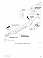
and for the safe, reliable operation of the vehicle. All
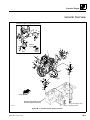
references to the right side, left side, front, and rear are
given from the perspective of the operator's position,
facing forward (see figure below).
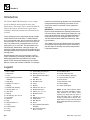
The Section Contents allows the user to quickly locate
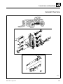
any desired section. Each section begins with its own
table of contents, and, where applicable, an informative
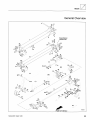
introduction and exploded-view illustration appears, to
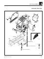
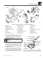
show the location of major section components.
Provision for supplementary information is made by
Trak International in the form of Service Bulletins,
Service Campaigns, Service Training Schools, the
OmniQuip web site, other literature, and through
updates to the manual itself. Comments and suggestions for improvement are welcomed and encouraged.
All information, illustrations and specifications contained in this manual are based on the latest product
information available at the time of publication
approval. Trak reserves the right to make changes and
improvements to its products, and to discontinue the
manufacture of any product, at its discretion at any time
without public notice or obligation. When additional
information is desired to satisfy a situation not covered
sufficiently, consult the nearest Sky Trak International
distributor, or the Sky Trak International Service
Department at 1-414-268-8959.
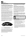
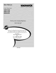
FRONT
TOP
LEFT
RIGHT
FRONT
REAR
BOTTOM
MS2240
REAR
All references to direction are as viewed from the operator’s position, facing forward.
© 1999 Sky Trak International
Model 3606 • Origin 10/99
i
Section Contents
Section
Subject
Page
Section 1
1.1
1.2
1.3
1.4
1.5
1.6
Safety . . . . . . . . . . . . . . . . . . . . . . . . . . . . . . . . . . . . . . . . . . . . . . . . . . .
INTRODUCTION . . . . . . . . . . . . . . . . . . . . . . . . . . . . . . . . . . . . . . . . . . .
OWNERS/OPERATORS MANUAL . . . . . . . . . . . . . . . . . . . . . . . . . . . . . .
SAFETY INFORMATION . . . . . . . . . . . . . . . . . . . . . . . . . . . . . . . . . . . . .
ACCIDENT PREVENTION TAGS . . . . . . . . . . . . . . . . . . . . . . . . . . . . . . .
SAFETY INSTRUCTIONS . . . . . . . . . . . . . . . . . . . . . . . . . . . . . . . . . . . .
SAFETY DECALS . . . . . . . . . . . . . . . . . . . . . . . . . . . . . . . . . . . . . . . . . .
1-1
1-2
1-2
1-2
1-3
1-4
1-5
Section 2
2.1
2.2
2.3
2.4
2.5
2.6
2.7
2.8
2.9
2.10
2.11
2.12
2.13
General Information, Specifications, and Maintenance . . . . . . . . . . .
REPLACEMENT PARTS AND WARRANTY INFORMATION. . . . . . . . . .
SERIAL NUMBER LOCATIONS . . . . . . . . . . . . . . . . . . . . . . . . . . . . . . . .
TORQUE VALUES . . . . . . . . . . . . . . . . . . . . . . . . . . . . . . . . . . . . . . . . . .
SPECIFICATIONS . . . . . . . . . . . . . . . . . . . . . . . . . . . . . . . . . . . . . . . . . .
FLUIDS, LUBRICANTS AND CAPACITIES . . . . . . . . . . . . . . . . . . . . . . .
CLEANING . . . . . . . . . . . . . . . . . . . . . . . . . . . . . . . . . . . . . . . . . . . . . . . .
REPLACEMENT . . . . . . . . . . . . . . . . . . . . . . . . . . . . . . . . . . . . . . . . . . . .
HOSES AND TUBES . . . . . . . . . . . . . . . . . . . . . . . . . . . . . . . . . . . . . . . .
BEARINGS . . . . . . . . . . . . . . . . . . . . . . . . . . . . . . . . . . . . . . . . . . . . . . . .
PRESSURE TESTING AND ADJUSTMENT . . . . . . . . . . . . . . . . . . . . . .
AFTER SERVICE STARTUP AND CHECKS . . . . . . . . . . . . . . . . . . . . . .
MAINTENANCE INSTRUCTIONS . . . . . . . . . . . . . . . . . . . . . . . . . . . . . .
EMERGENCY OPERATIONS. . . . . . . . . . . . . . . . . . . . . . . . . . . . . . . . . .
2-1
2-3
2-3
2-3
2-6
2-9
2-14
2-14
2-14
2-14
2-15
2-15
2-17
2-41
Section 3
Boom . . . . . . . . . . . . . . . . . . . . . . . . . . . . . . . . . . . . . . . . . . . . . . . . . . . .
INTRODUCTION. . . . . . . . . . . . . . . . . . . . . . . . . . . . . . . . . . . . . . . . . . . . . . . . .
3.1
SPECIFICATIONS . . . . . . . . . . . . . . . . . . . . . . . . . . . . . . . . . . . . . . . . . .
3.2
BOOM ASSEMBLY . . . . . . . . . . . . . . . . . . . . . . . . . . . . . . . . . . . . . . . . . .
3.3
QUICK-ATTACH ASSEMBLY . . . . . . . . . . . . . . . . . . . . . . . . . . . . . . . . . .
3.4
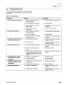
TROUBLESHOOTING . . . . . . . . . . . . . . . . . . . . . . . . . . . . . . . . . . . . . . .
3-1
3-2
3-4
3-4
3-23
3-25
Section 4
Cab, Covers and Mirrors . . . . . . . . . . . . . . . . . . . . . . . . . . . . . . . . . . . .
INTRODUCTION. . . . . . . . . . . . . . . . . . . . . . . . . . . . . . . . . . . . . . . . . . . . . . . . .
4.1
SERIAL NUMBER DECAL . . . . . . . . . . . . . . . . . . . . . . . . . . . . . . . . . . . .
4.2
CAB REPLACEMENT. . . . . . . . . . . . . . . . . . . . . . . . . . . . . . . . . . . . . . . .
4.3
CAB COVERS AND GUARDS . . . . . . . . . . . . . . . . . . . . . . . . . . . . . . . . .
4-1
4-2
4-4
4-4
4-21
Section 5
Axles, Wheels and Tires . . . . . . . . . . . . . . . . . . . . . . . . . . . . . . . . . . . .
INTRODUCTION. . . . . . . . . . . . . . . . . . . . . . . . . . . . . . . . . . . . . . . . . . . . . . . . .
5.1
GENERAL INFORMATION . . . . . . . . . . . . . . . . . . . . . . . . . . . . . . . . . . . .
5.2
AXLE ASSEMBLIES . . . . . . . . . . . . . . . . . . . . . . . . . . . . . . . . . . . . . . . . .
5.3
WHEELS AND TIRES . . . . . . . . . . . . . . . . . . . . . . . . . . . . . . . . . . . . . . .
5-1
5-2
5-4
5-4
5-9
ii
Model 3606 • Origin 10/99
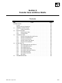
Section 6
Transfer Case and Drive Shafts . . . . . . . . . . . . . . . . . . . . . . . . . . . . . .
INTRODUCTION. . . . . . . . . . . . . . . . . . . . . . . . . . . . . . . . . . . . . . . . . . . . . . . . .
6.1
GENERAL INSTRUCTIONS . . . . . . . . . . . . . . . . . . . . . . . . . . . . . . . . . . .
6.2
SPECIFICATIONS . . . . . . . . . . . . . . . . . . . . . . . . . . . . . . . . . . . . . . . . . .
6.3
TRANSFER CASE . . . . . . . . . . . . . . . . . . . . . . . . . . . . . . . . . . . . . . . . . .
6.4
DRIVE SHAFTS . . . . . . . . . . . . . . . . . . . . . . . . . . . . . . . . . . . . . . . . . . . .
6.5
TROUBLESHOOTING . . . . . . . . . . . . . . . . . . . . . . . . . . . . . . . . . . . . . . .
6-1
6-2
6-4
6-4
6-4
6-6
6-9
Section 7
Transmission: Clark-Hurth T 12000 . . . . . . . . . . . . . . . . . . . . . . . . . . .
INTRODUCTION. . . . . . . . . . . . . . . . . . . . . . . . . . . . . . . . . . . . . . . . . . . . . . . . .
7.1
TRANSMISSION SERIAL NUMBER . . . . . . . . . . . . . . . . . . . . . . . . . . . .
7.2
TRANSMISSION SPECIFICATIONS . . . . . . . . . . . . . . . . . . . . . . . . . . . .
7.3
TOWING A DISABLED VEHICLE. . . . . . . . . . . . . . . . . . . . . . . . . . . . . . .
7.4
TRANSMISSION MAINTENANCE . . . . . . . . . . . . . . . . . . . . . . . . . . . . . .
7.5
TRANSMISSION REPLACEMENT. . . . . . . . . . . . . . . . . . . . . . . . . . . . . .
7.6
TRANSMISSION TROUBLESHOOTING . . . . . . . . . . . . . . . . . . . . . . . . .
7-1
7-2
7-4
7-4
7-4
7-5
7-6
7-11
Section 8A Engine: Perkins 1004 Series . . . . . . . . . . . . . . . . . . . . . . . . . . . . . . . . .
INTRODUCTION. . . . . . . . . . . . . . . . . . . . . . . . . . . . . . . . . . . . . . . . . . . . . . . . .
8A.1 SAFETY INFORMATION . . . . . . . . . . . . . . . . . . . . . . . . . . . . . . . . . . . . .
8A.2 PERKINS ENGINE SERIAL NUMBER . . . . . . . . . . . . . . . . . . . . . . . . . . .
8A.3 PERKINS SPECIFICATIONSAND MAINTENANCE INFORMATION . . . .
8A.4 PERKINS ENGINE STANDARD PRACTICES . . . . . . . . . . . . . . . . . . . . .
8A.5 PERKINS ENGINE COOLING SYSTEM . . . . . . . . . . . . . . . . . . . . . . . . .
8A.6 PERKINS ENGINEELECTRICAL SYSTEM . . . . . . . . . . . . . . . . . . . . . . .
8A.7 PERKINS ENGINE FUEL SYSTEM . . . . . . . . . . . . . . . . . . . . . . . . . . . . .
8A.8 PERKINS ENGINE EXHAUST SYSTEM . . . . . . . . . . . . . . . . . . . . . . . . .
8A.9 PERKINS ENGINE REPLACEMENT . . . . . . . . . . . . . . . . . . . . . . . . . . . .
8A.10 PERKINS ENGINE STORAGE . . . . . . . . . . . . . . . . . . . . . . . . . . . . . . . . .
8A.11 TROUBLESHOOTING . . . . . . . . . . . . . . . . . . . . . . . . . . . . . . . . . . . . . . .
8A1
8A-2
8A4
8A6
8A6
8A6
8A6
8A10
8A10
8A15
8A16
8A22
8A24
Section 8B Engine: Cummins 4BT3.9 . . . . . . . . . . . . . . . . . . . . . . . . . . . . . . . . . . .
INTRODUCTION. . . . . . . . . . . . . . . . . . . . . . . . . . . . . . . . . . . . . . . . . . . . . . . . .
8B.1 SAFETY INFORMATION . . . . . . . . . . . . . . . . . . . . . . . . . . . . . . . . . . . . .
8B.2 CUMMINS ENGINE SERIAL NUMBER . . . . . . . . . . . . . . . . . . . . . . . . . .
8B.3 CUMMINS SPECIFICATIONS AND MAINTENANCE INFORMATION. . .
8B.4 CUMMINS ENGINE STANDARD PRACTICES . . . . . . . . . . . . . . . . . . . .
8B.5 CUMMINS ENGINE COOLING SYSTEM. . . . . . . . . . . . . . . . . . . . . . . . .
8B.6 CUMMINS ENGINE ELECTRICAL SYSTEM . . . . . . . . . . . . . . . . . . . . . .
8B.7 CUMMINS ENGINE FUEL SYSTEM . . . . . . . . . . . . . . . . . . . . . . . . . . . .
8B.8 CUMMINS ENGINE EXHAUST SYSTEM . . . . . . . . . . . . . . . . . . . . . . . .
8B.9 CUMMINS ENGINE REPLACEMENT . . . . . . . . . . . . . . . . . . . . . . . . . . .
8B.10 CUMMINS ENGINE STORAGE . . . . . . . . . . . . . . . . . . . . . . . . . . . . . . . .
8B.11 TROUBLESHOOTING . . . . . . . . . . . . . . . . . . . . . . . . . . . . . . . . . . . . . . .
8B-1
8B-2
8B-4
8B-6
8B-6
8B-6
8B-6
8B-10
8B-10
8B-15
8B-16
8B-22
8B-23
Model 3606 • Origin 10/99
iii
Section 9
Hydraulic System . . . . . . . . . . . . . . . . . . . . . . . . . . . . . . . . . . . . . . . . . .
9-1
INTRODUCTION. . . . . . . . . . . . . . . . . . . . . . . . . . . . . . . . . . . . . . . . . . . . . . . . .
9-2
9.1
SAFETY INFORMATION . . . . . . . . . . . . . . . . . . . . . . . . . . . . . . . . . . . . .
9-4
9.2
SPECIFICATIONS . . . . . . . . . . . . . . . . . . . . . . . . . . . . . . . . . . . . . . . . . .
9-4
9.3
HYDRAULIC PRESSURE DIAGNOSIS . . . . . . . . . . . . . . . . . . . . . . . . . .
9-4
9.4
HYDRAULIC FLUID . . . . . . . . . . . . . . . . . . . . . . . . . . . . . . . . . . . . . . . . .
9-8
9.5
HOSES, TUBE LINES, FITTINGS, ETC. . . . . . . . . . . . . . . . . . . . . . . . . .
9-9
9.6
HYDRAULIC RESERVOIR . . . . . . . . . . . . . . . . . . . . . . . . . . . . . . . . . . . . 9-10
9.7
HYDRAULIC SYSTEM PUMP . . . . . . . . . . . . . . . . . . . . . . . . . . . . . . . . . 9-12
9.8
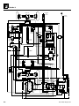
HYDRAULIC CIRCUITS . . . . . . . . . . . . . . . . . . . . . . . . . . . . . . . . . . . . . . 9-19
9.9
VALVES AND MANIFOLDS . . . . . . . . . . . . . . . . . . . . . . . . . . . . . . . . . . . 9-64
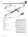
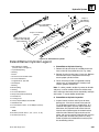
9.10 CYLINDERS . . . . . . . . . . . . . . . . . . . . . . . . . . . . . . . . . . . . . . . . . . . . . . . 9-86
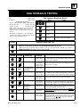
9.11 TROUBLESHOOTING . . . . . . . . . . . . . . . . . . . . . . . . . . . . . . . . . . . . . . . 9-117
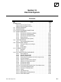
Section 10 Electrical System . . . . . . . . . . . . . . . . . . . . . . . . . . . . . . . . . . . . . . . . . .
INTRODUCTION. . . . . . . . . . . . . . . . . . . . . . . . . . . . . . . . . . . . . . . . . . . . . . . . .
10.1 SERVICE WARNINGS . . . . . . . . . . . . . . . . . . . . . . . . . . . . . . . . . . . . . . .
10.2 SPECIFICATIONS . . . . . . . . . . . . . . . . . . . . . . . . . . . . . . . . . . . . . . . . . .
10.3 EFFECTIVE GROUND CONNECTIONS . . . . . . . . . . . . . . . . . . . . . . . . .
10.4 WIRING HARNESSES . . . . . . . . . . . . . . . . . . . . . . . . . . . . . . . . . . . . . . .
10.5 FUSES AND RELAYS . . . . . . . . . . . . . . . . . . . . . . . . . . . . . . . . . . . . . . .
10.6 ENGINE START CIRCUIT . . . . . . . . . . . . . . . . . . . . . . . . . . . . . . . . . . . .
10.7 CHARGING CIRCUIT . . . . . . . . . . . . . . . . . . . . . . . . . . . . . . . . . . . . . . . .
10.8 ELECTRICAL SYSTEM COMPONENTS . . . . . . . . . . . . . . . . . . . . . . . . .
10.9 ELECTRICAL SYSTEM TROUBLESHOOTING . . . . . . . . . . . . . . . . . . . .
iv
10-1
10-3
10-7
10-8
10-8
10-9
10-36
10-37
10-42
10-49
10-84
Model 3606 • Origin 10/99
Section 1
Safety
Contents
PAR.
1.1
1.2
1.3
1.4
1.5
1.6
Model 3606 • Origin 10/99
TITLE
INTRODUCTION . . . . . . . . . . . . . . . . . . . . . . . . . . . . . . . . . . . . . . . . . . .
OWNERS/OPERATORS MANUAL . . . . . . . . . . . . . . . . . . . . . . . . . . . . . .
SAFETY INFORMATION . . . . . . . . . . . . . . . . . . . . . . . . . . . . . . . . . . . . .
1.3.1
Safety Alert Symbol. . . . . . . . . . . . . . . . . . . . . . . . . . . . . . . . . .
1.3.2
Signal Words . . . . . . . . . . . . . . . . . . . . . . . . . . . . . . . . . . . . . . .
ACCIDENT PREVENTION TAGS . . . . . . . . . . . . . . . . . . . . . . . . . . . . . . .
SAFETY INSTRUCTIONS . . . . . . . . . . . . . . . . . . . . . . . . . . . . . . . . . . . .
1.5.1
Personal Hazards . . . . . . . . . . . . . . . . . . . . . . . . . . . . . . . . . . .
1.5.2
Equipment Hazards. . . . . . . . . . . . . . . . . . . . . . . . . . . . . . . . . .
1.5.3
General Hazards . . . . . . . . . . . . . . . . . . . . . . . . . . . . . . . . . . . .
1.5.4
Operational Hazards . . . . . . . . . . . . . . . . . . . . . . . . . . . . . . . . .
SAFETY DECALS. . . . . . . . . . . . . . . . . . . . . . . . . . . . . . . . . . . . . . . . . . .
PAGE
1-2
1-2
1-2
1-3
1-3
1-3
1-4
1-4
1-4
1-4
1-4
1-5
1-1
Section 1
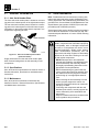
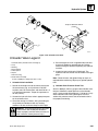
1.1 INTRODUCTION
WITHOUT CLOSED CAB
Sky Trak International (hereafter, Sky Trak) products
meet all applicable industry safety standards. Sky Trak
actively promotes safe practices in the use and maintenance of its products through training programs, instructional manuals, and the pro-active efforts of all
employees involved in engineering, design, manufacture,
marketing and service.
Many factors contribute to unsafe conditions: carelessness,
fatigue, overload, inattentiveness, unfamiliarity, even
drugs and alcohol, among others. Although equipment
damage can usually be repaired in a brief period of time,
death and irreparable injury are permanent. For optimal
safety, encourage everyone to think, and to act, safely.
Read, understand and follow the information in this manual, and obey all locally-approved safety practices, procedures, rules, codes, regulations and laws. Prior to
performing any maintenance on the vehicle, consider all
factors, circumstances and conditions which can have an
effect upon the safety of personnel and equipment, and
take appropriate action to ensure the safety of all
involved.
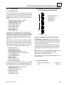
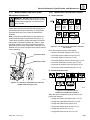
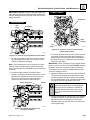
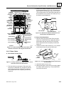
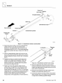
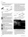
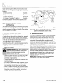
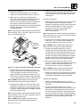
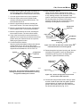
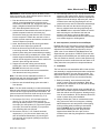
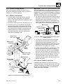
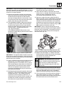
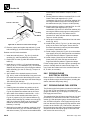
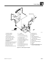
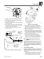
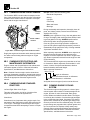
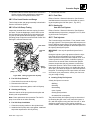
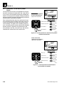
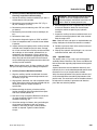
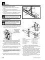
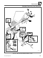
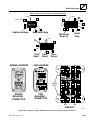
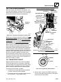
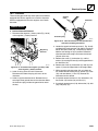
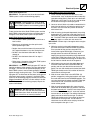
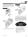
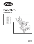
Seat Base (ref.)
Owners/Operators
Manual Holder
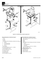
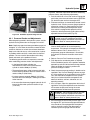
Figure 1–1. The Owners/Operators Manual holder is
located beneath the seat (without closed cab option).
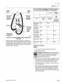
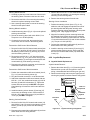
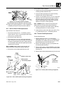
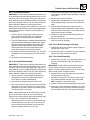
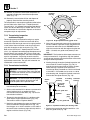
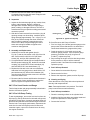
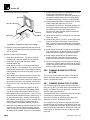
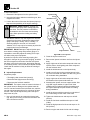
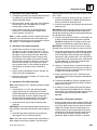
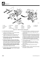
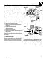
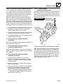
WITH CLOSED CAB
FRONT
Seat Base
(ref.)
These instructions cannot cover all details or variations in
the equipment, procedures, or processes described, nor
provide directions for meeting every possible contingency
during operation, maintenance, or testing. When additional
information is desired to satisfy a situation not covered
sufficiently, consult the local Sky Trak distributor or the
Sky Trak Service Department at 1-800-439-8959.
1.2
OWNERS/OPERATORS MANUAL
The vehicle must be driven and operated as a consequence
of, or when performing, service, maintenance and test procedures. The service technician must, therefore, thoroughly read, understand, and follow the Sky Trak 3606
Owners/Operators Manual.
An owners/operators manual is supplied with each vehicle
and must be kept in the holder or storage compartment
located to the left and below the operators seat (for vehicles without the closed cab option, see Fig. 1–1; for vehicles with the closed cab option, see Fig. 1–2).
In the event that the owners/operators manual is missing,
consult the local Sky Trak distributor or the Sky Trak Service Department before proceeding.
1-2
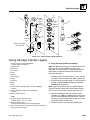
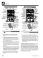
MS2630
FRONT
Owners/Operators
Manual Holder
MS2620
Figure 1–2. The Owners/Operators Manual holder is
located at the left side of the seat base (closed cab option).
1.3
SAFETY INFORMATION
The following information provides general safety instructions, including signal words, hazard statement definitions,
notification of hazards, methods to help avoid hazards,
and the consequences of failing to follow the safety
information. For safe maintenance of the vehicle, read,
understand and follow all DANGER, WARNING, and
CAUTION information.
The information in this manual does not replace any
other safety rules or proper judgment. Governmental
authorities and employers also have their own sets of
rules, codes, regulations and laws. Before starting work
at a site, check with the supervisor or safety coordinator
and ask about the safety policy. Learn the safety requirements in effect before operating, maintaining, servicing
or testing the vehicle. Safety depends on following safety
requirements.
Model 3606 • Origin 10/99
Safety
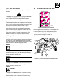
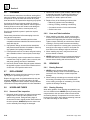
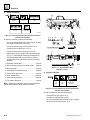
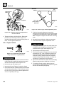
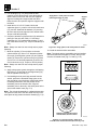
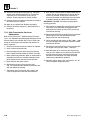
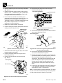
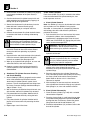
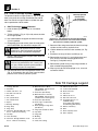
1.3.1 Safety Alert Symbol
1.4
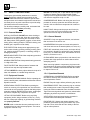
ACCIDENT PREVENTION TAGS
The exclamation mark within a triangle is the Safety Alert
Symbol.
The Safety Alert Symbol means ATTENTION! BECOME
ALERT! YOUR SAFETY IS INVOLVED! The symbol is
used to attract attention to safety hazards found on
vehicle safety decals and throughout this manual.
The message that follows the symbol contains important
information about Safety. To avoid possible death or
injury, carefully read and follow all safety messages. Fully
understand the potential causes of death or injury.
Also, know where to obtain medical assistance, how to
use a first-aid kit and fire extinguisher/fire suppression
system. Keep emergency telephone numbers (fire and
police departments, ambulance, rescue squad or paramedics, etc.) nearby. If working alone, routinely check
with another person to help assure personal safety.
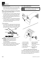
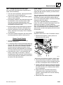
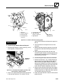
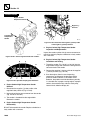
OS2180
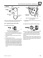
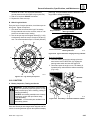
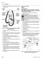
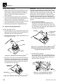
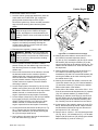
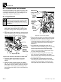
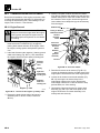
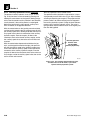
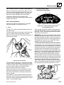
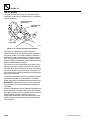
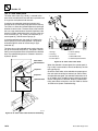
Figure 1–3. Accident Prevention Tag.
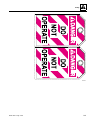
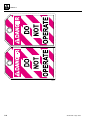
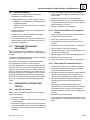
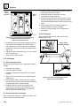
Before beginning any maintenance or service, place an
Accident Prevention Tag on both the ignition switch and
the steering wheel (Fig. 1–4), stating that the vehicle
should not be operated. Copies of Accident Prevention
Tags are provided on pages 1-9 and 1-10.
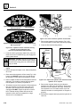
1.3.2 Signal Words
Three types of hazard statements are used in this manual. Each signal word indicates the existence and degree
of relative risk of the hazard described within the statement that follows the signal word. The three types of hazard statements use the following signal words:
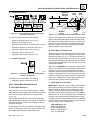
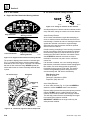
DANGER
DANGER:
DANGER
DANG
ER
The signal word DANGER denotes an extremely hazardous situation exists on or near the vehicle which would
result in a high probability of death or irreparable injury if
proper precautions are not taken.
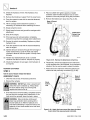
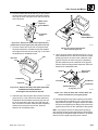
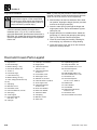
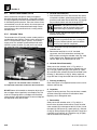
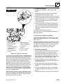
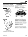
OS1520
WARNING
WARNING:
Figure 1–4. Place Accident Prevention Tags on both
the ignition switch and the steering wheel.
The signal word WARNING denotes a hazard exists on or
near the vehicle which can result in injury or death if the
proper precautions are not taken.
CAUTION
CAUTION:
The signal word CAUTION denotes a reminder of safety
practices or directs attention to unsafe practices on or
near the vehicle which could result in personal injury if
the proper precautions are not taken.
Model 3606 • Origin 10/99
1-3
Section 1
1.5
SAFETY INSTRUCTIONS
Following are general safety statements to consider
before performing maintenance procedures on the
vehicle. Additional statements related to specific tasks
and procedures are located throughout this manual and
are listed prior to any work instructions to provide safety
information before the hazard occurs.
For all safety messages, carefully read, understand and
follow the instructions before proceeding.
1.5.1 Personal Hazards
HAIR and CLOTHING: DO NOT wear loose clothing or
jewelry. Tie up or restrain hair. Wear the correct safety
equipment for the job (including but not limited to: hard
hat; safety shoes; safety glasses, goggles, or face shield;
heavy gloves; hearing protection; reflective clothing; wetweather gear; respirator or filter mask).
EYE PROTECTION: Always wear appropriate eye protection when chiseling, grinding, sanding, welding, painting, repairing hydraulic systems, or checking, testing or
charging the battery.
BREATHING PROTECTION: Wear respiratory protection
when grinding or painting.
HEARING PROTECTION: Always wear hearing protection
in a high-noise area.
FOOT PROTECTION: Wear protective footwear with
reinforced toe caps and slip-resistant soles.
LIFTING: NEVER lift a heavy object without the help of at
least one assistant or a suitable sling and hoist.
1.5.2 Equipment Hazards
OWNERS/OPERATORS MANUAL: Before operating the
vehicle, carefully read, understand and follow the Owners/
Operators manual.
DO NOT use a hoist, jack, or jack stands only to support
equipment. Always support equipment with propercapacity blocks or approved stands. Hoist or jack failure
can allow the equipment to tip or to fall.
COMPRESSED AIR: Before and during the use of compressed air, wear eye protection and advise other personnel in the work area that compressed air is about to
be used.
HAND TOOLS: Always use the proper tool for the job;
keep tools clean and in good working order, and use
special service tools only as recommended.
1.5.3 General Hazards
SOLVENTS: Only use approved solvents, and solvents
that are known to be safe for use.
HOUSEKEEPING: Keep the work area and operator’s
cab clean and remove all hazards (debris, oil, tools, etc.).
FIRST AID: Immediately clean, dress, and report all injuries resulting in bleeding or opened skin (cuts, abrasions,
burns, etc.), no matter how minor. Know where the First
Aid Kit is, and how to use it.
CLEANLINESS: Wear eye protection, and clean all components with a high-pressure or steam cleaner before
attempting service.
When removing hydraulic components, plug hose ends
and connections to prevent excess leakage and contamination. Place a suitable catch basin beneath the vehicle
to capture fluid run-off.
1.5.4 Operational Hazards
OPERATIONAL CONSIDERATIONS: Before operating
the vehicle, carefully read, understand and follow the
owners/operators manual.
ENGINE: Stop the engine before performing any service.
OPERATIONAL PROTECTION: Before operating the
vehicle or returning it for operational use, check that the
cab and all roll-over protection systems and falling-object
protection systems (ROPS/FOPS) are intact, undamaged
and secure. Replace any component as required.
DANGEROUS START: Place a warning sign on vehicles
that are dangerous to start. Disconnect battery leads if
leaving the vehicle unattended. Place Accident Prevention
Tags on the steering wheel and ignition key switch before
attempting to perform any service or maintenance.
LIFTING OF EQUIPMENT: Before using any lifting
equipment (chains, slings, brackets, hooks, etc.), verify
that it is of the proper capacity, in good working condition,
and properly attached.
VENTILATION: Avoid prolonged engine operation in
enclosed areas with inadequate ventilation.
NEVER stand or otherwise become positioned under a
suspended load or under raised equipment. The load or
equipment could fall or tip.
1-4
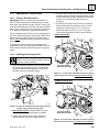
RADIATOR CAP: Always wear steam-resistant, heatprotective gloves when opening the radiator cap. Cover
cap with a clean, thick cloth and turn slowly to the first
stop to relieve pressure.
Model 3606 • Origin 10/99
Safety
SOFT SURFACES AND SLOPES: NEVER work on a
vehicle parked on soft surfaces or slopes (inclined ground
or hills). Vehicle must be on hard, level surface with
wheels blocked when necessary before performing any
service. Obtain assistance, block all wheels, and add
supports if necessary before beginning any work.
SUPPORTS AND STRAPS: Install safe, stable supports,
slings or straps beneath or around a component or structural member before beginning any work.
FLUID PRESSURE: Before loosening any hydraulic or
diesel component, hoses or tubes, turn engine OFF. Wear
heavy, protective gloves and eye protection. NEVER
check for leaks using any part of your body; use a piece
of cardboard or wood instead. If injured, see a doctor
immediately. Diesel fuel leaking under pressure can
explode. Hydraulic fluid and diesel fuel leaking under
pressure can penetrate the skin, cause infection, gangrene, and other serious personal injury. Relieve all pressure before disconnecting any component, part, line or
hose. Slowly loosen parts and allow release of residual
pressure before removing any part or component. Before
starting engine or applying pressure, use components,
parts, hoses and pipes that are in good condition, connected and tightened to the proper torque. Capture fluid
in an appropriate container and dispose of in accordance
with prevailing environmental regulations.
1.6
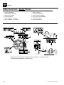
SAFETY DECALS
Locations of vehicle safety and other decals are shown
on the following pages. As part of routine maintenance,
check that ALL safety and informational decals on the
vehicle are present and readable. Keep the safety decals
clean. If a replacement decal is needed, refer to the
owners/operators manual and parts catalog for the latest
parts numbers and ordering information. Or, contact
OmniQuip Parts Worldwide directly at:
1-888-872-5123
PRESSURE TESTING: When conducting any test, only
use test equipment that is correctly calibrated and in
good condition. Use the correct equipment in the proper
manner, and make changes or repairs as indicated by the
test procedures to achieve the desired results.
LEAVING VEHICLE: Lower the attachment to the ground
before leaving the vehicle.
TIRE PRESSURE: Always keep tires inflated to the
proper pressure to help prevent dangerous travel and
load-handling situations. DO NOT over-inflate tires.
Model 3606 • Origin 10/99
1-5
Section 1
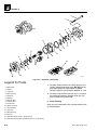
Safety Decal List – Earlier Models
1.
2.
3.
4.
5.
6.
7.
8.
9.
10.
11.
12.
No Riders WARNING
Vehicle Rollaway WARNING
Electrocution DANGER
Load Chart Booklet
Tipover DANGER – Operating
Tipover DANGER – Tire Pressure
DANGER
CONTACTING
ELECTRIC
POWER LINES
can result in
electrocution.
NEVER operate
vehicle within
10 feet (3m) of
electric power
lines.
3
Safety Instructions
Moving Parts WARNING
Explosive Gases WARNING
Carrying Personnel WARNING
Boom Extend Stripes
Boom Angle Indicator
DANGER
LOW TIRE
PRESSURE
can result
in tipover.
6
MAINTAIN
proper tire
pressure at
all times.
9
5
2
4
8
11
SAFETY INSTRUCTIONS
1
1. Read operators manual
before operating.
2. Fasten seat belt.
3. Allow no riders.
7
12
10
4. Use an approved work
platform to lift or lower
personnel.
OS1511
OS1256
Note: Many of these hazard related decals are available free of charge by calling
OmniQuip Parts Worldwide at 1-888-872-5123.
1-6
Model 3606 • Origin 10/99
Safety
Safety Decal List – Later Models
1.
2.
3.
4.
5.
6.
7.
8.
9.
10.
11.
12.
No Riders WARNING
Vehicle Rollaway WARNING
Electrocution DANGER
Load Chart Booklet
Tipover DANGER – Operating
Tipover DANGER – Tire Pressure
DANGER
NEVER operate
vehicle within
10 feet (3m) of
electric power
lines.
CONTACTING
ELECTRIC
POWER LINES
can result in
electrocution.
VEHICLE
TIPOVER
can result
in death or
serious injury.
DANGER
DO NOT raise
boom while
on a slope
unless load
is level.
DO NOT
travel
with the
boom
raised.
Safety Instructions
Moving Parts WARNING
Explosive Gases WARNING
Carrying Personnel WARNING
Boom Extend Stripes
Boom Angle Indicator
5
3
DANGER
6
LOW TIRE PRESSURE
can result in tipover.
MAINTAIN
proper tire
pressure at
all times.
9
SAFETY INSTRUCTIONS
1. Read operators manual
before operating.
3. Allow no riders.
2. Fasten seat belt.
4. Use an approved work
platform to lift or lower
personnel.
7
2
WARNING
VEHICLE
ROLLAWAY
can cause
death or
serious
injury.
4
ALWAYS
engage
parking
brake
before
dismounting.
8
WARNING
11
12
10
1
Allow no riders.
OS1241
OS1255
Note: Many of these hazard related decals are available free of charge by calling
OmniQuip Parts Worldwide at 1-888-872-5123.
Model 3606 • Origin 10/99
1-7
Section 1
Copies of Accident Prevention Tags are provided on pages 1-9 and 1-10.
1-8
Model 3606 • Origin 10/99
Safety
OS2180
Model 3606 • Origin 10/99
1-9
Section 1
OS2180
1-10
Model 3606 • Origin 10/99
Section 2
General Information, Specifications, and Maintenance
Contents
PAR.
2.1
2.2
2.3
TITLE
REPLACEMENT PARTS AND WARRANTY INFORMATION . . . . . . . . . .
SERIAL NUMBER LOCATIONS . . . . . . . . . . . . . . . . . . . . . . . . . . . . . . . .
TORQUE VALUES . . . . . . . . . . . . . . . . . . . . . . . . . . . . . . . . . . . . . . . . . .
2.3.1
Fastener Rating . . . . . . . . . . . . . . . . . . . . . . . . . . . . . . . . . . . . .
2.3.2
Straight Thread O-ring Fitting (non-adjustable) . . . . . . . . . . . . .
2.3.3
Straight Thread O-ring Fitting (adjustable) . . . . . . . . . . . . . . . .
2.3.4
Metric Conversion Factors. . . . . . . . . . . . . . . . . . . . . . . . . . . . .
2.4
SPECIFICATIONS . . . . . . . . . . . . . . . . . . . . . . . . . . . . . . . . . . . . . . . . . .
2.4.1
Vehicle Dimensions (Fig. 2-1) . . . . . . . . . . . . . . . . . . . . . . . . . .
2.4.2
Performance Specifications. . . . . . . . . . . . . . . . . . . . . . . . . . . .
2.4.3
Weights . . . . . . . . . . . . . . . . . . . . . . . . . . . . . . . . . . . . . . . . . . .
2.4.4
Miscellaneous Specifications . . . . . . . . . . . . . . . . . . . . . . . . . .
2.5
FLUIDS, LUBRICANTS AND CAPACITIES . . . . . . . . . . . . . . . . . . . . . . .
2.5.1
Axles (Differential Housings) and Transfer Case . . . . . . . . . . . .
2.5.2
Wheel Ends . . . . . . . . . . . . . . . . . . . . . . . . . . . . . . . . . . . . . . . .
2.5.3
Lubrication Points (grease fittings) . . . . . . . . . . . . . . . . . . . . . .
2.5.4
Hydraulic System . . . . . . . . . . . . . . . . . . . . . . . . . . . . . . . . . . .
2.5.5
Engine . . . . . . . . . . . . . . . . . . . . . . . . . . . . . . . . . . . . . . . . . . . .
2.5.6
Transmission . . . . . . . . . . . . . . . . . . . . . . . . . . . . . . . . . . . . . . .
2.5.7
Drive Shaft Splines . . . . . . . . . . . . . . . . . . . . . . . . . . . . . . . . . .
2.5.8
General Anti-corrosion . . . . . . . . . . . . . . . . . . . . . . . . . . . . . . .
2.5.9
Electrical . . . . . . . . . . . . . . . . . . . . . . . . . . . . . . . . . . . . . . . . . .
2.5.10
Paint . . . . . . . . . . . . . . . . . . . . . . . . . . . . . . . . . . . . . . . . . . . . .
2.5.11
Thread Locking Compound . . . . . . . . . . . . . . . . . . . . . . . . . . . .
2.6
CLEANING . . . . . . . . . . . . . . . . . . . . . . . . . . . . . . . . . . . . . . . . . . . . . . . .
2.7
REPLACEMENT . . . . . . . . . . . . . . . . . . . . . . . . . . . . . . . . . . . . . . . . . . . .
2.8
HOSES AND TUBES . . . . . . . . . . . . . . . . . . . . . . . . . . . . . . . . . . . . . . . .
2.8.1
Hose and Tube Inspection . . . . . . . . . . . . . . . . . . . . . . . . . . . . .
2.8.2
Hose and Tube Installation . . . . . . . . . . . . . . . . . . . . . . . . . . . .
2.9
BEARINGS . . . . . . . . . . . . . . . . . . . . . . . . . . . . . . . . . . . . . . . . . . . . . . . .
2.9.1
Bearing Removal . . . . . . . . . . . . . . . . . . . . . . . . . . . . . . . . . . . .
2.9.2
Bearing Cleaning. . . . . . . . . . . . . . . . . . . . . . . . . . . . . . . . . . . .
2.9.3
Bearing Installation . . . . . . . . . . . . . . . . . . . . . . . . . . . . . . . . . .
2.10 PRESSURE TESTING AND ADJUSTMENT . . . . . . . . . . . . . . . . . . . . . .
2.11 AFTER SERVICE STARTUP AND CHECKS . . . . . . . . . . . . . . . . . . . . . .
2.11.1
After Service Startup . . . . . . . . . . . . . . . . . . . . . . . . . . . . . . . . .
2.11.2
After Electrical/Electronic Component Service . . . . . . . . . . . . .
2.11.3
After Hydraulic Component Service . . . . . . . . . . . . . . . . . . . . .
Model 3606 • Origin 10/99
PAGE
2-3
2-3
2-3
2-3
2-3
2-3
2-4
2-6
2-6
2-6
2-7
2-8
2-9
2-9
2-9
2-9
2-10
2-10
2-11
2-12
2-12
2-12
2-13
2-13
2-14
2-14
2-14
2-14
2-14
2-14
2-14
2-14
2-15
2-15
2-15
2-15
2-15
2-15
2-1
Section 2
2.11.4
After Brake System Service . . . . . . . . . . . . . . . . . . . . . . . . . . .
2.11.5
After Fuel System Service. . . . . . . . . . . . . . . . . . . . . . . . . . . . .
2.11.6
After Transmission Service or Replacement . . . . . . . . . . . . . . .
2.11.7
After Tire and Wheel Service . . . . . . . . . . . . . . . . . . . . . . . . . .
2.11.8
After Engine Service . . . . . . . . . . . . . . . . . . . . . . . . . . . . . . . . .
2.11.9
After Boom Service . . . . . . . . . . . . . . . . . . . . . . . . . . . . . . . . . .
2.11.10 After Axle Service . . . . . . . . . . . . . . . . . . . . . . . . . . . . . . . . . . .
2.12 MAINTENANCE INSTRUCTIONS . . . . . . . . . . . . . . . . . . . . . . . . . . . . . .
2.12.1
Maintenance Schedule and Checklist . . . . . . . . . . . . . . . . . . . .
2.12.2
Boom Wear Pad Maintenance. . . . . . . . . . . . . . . . . . . . . . . . . .
2.12.3
Air Cleaner . . . . . . . . . . . . . . . . . . . . . . . . . . . . . . . . . . . . . . . .
2.12.4
Optional Closed Cab Air Filters . . . . . . . . . . . . . . . . . . . . . . . . .
2.12.5
Engine Cooling System . . . . . . . . . . . . . . . . . . . . . . . . . . . . . . .
2.12.6
Engine Oil and Filter . . . . . . . . . . . . . . . . . . . . . . . . . . . . . . . . .
2.12.7
Engine Fuel System . . . . . . . . . . . . . . . . . . . . . . . . . . . . . . . . .
2.12.8
Engine Fan Belt . . . . . . . . . . . . . . . . . . . . . . . . . . . . . . . . . . . . .
2.12.9
Hydraulic System Oil And Filter. . . . . . . . . . . . . . . . . . . . . . . . .
2.12.10 Transmission Oil And Filter . . . . . . . . . . . . . . . . . . . . . . . . . . . .
2.12.11 Axle Oil . . . . . . . . . . . . . . . . . . . . . . . . . . . . . . . . . . . . . . . . . . .
2.12.13 Transfer Case Oil. . . . . . . . . . . . . . . . . . . . . . . . . . . . . . . . . . . .
2.12.14 Wheels and Tires . . . . . . . . . . . . . . . . . . . . . . . . . . . . . . . . . . .
2.12.15 BATTERY . . . . . . . . . . . . . . . . . . . . . . . . . . . . . . . . . . . . . . . . .
2.12.16 Fuse and Relay Replacement . . . . . . . . . . . . . . . . . . . . . . . . . .
2.12.17 Boom Chains. . . . . . . . . . . . . . . . . . . . . . . . . . . . . . . . . . . . . . .
2.12.18 Storage . . . . . . . . . . . . . . . . . . . . . . . . . . . . . . . . . . . . . . . . . . .
2.12.19 Transport . . . . . . . . . . . . . . . . . . . . . . . . . . . . . . . . . . . . . . . . . .
2.13 EMERGENCY OPERATIONS. . . . . . . . . . . . . . . . . . . . . . . . . . . . . . . . . .
2.13.1
Towing a Disabled Vehicle . . . . . . . . . . . . . . . . . . . . . . . . . . . . .
2-2
2-16
2-16
2-16
2-16
2-16
2-16
2-16
2-17
2-17
2-19
2-20
2-21
2-22
2-23
2-25
2-28
2-29
2-31
2-32
2-34
2-34
2-35
2-37
2-39
2-40
2-40
2-41
2-41
Model 3606 • Origin 10/99
General Information, Specifications, and Maintenance
2.1
2.3.2
REPLACEMENT PARTS AND
WARRANTY INFORMATION
The replacement of any part with any other than a Sky
Trak authorized replacement part can adversely affect
the safety, performance, or durability of the vehicle, and
may void the warranty. Sky Trak International assumes
no liability whatsoever for unauthorized replacement
parts.
A warranty registration form must be filled out by the Sky
Trak distributor, signed by the purchaser, and returned to
Sky Trak when the vehicle is sold and/or put into use.
Registration activates the warranty period and helps to
assure that warranty claims are promptly processed. To
guarantee full warranty service, verify that the distributor
has returned the business reply card of the warranty registration form to Sky Trak.
2.2
SERIAL NUMBER LOCATIONS
When ordering replacement parts or making service
inquiries about the vehicle, various serial numbers are
required to help assure the provision of
correct parts and information. Before ordering parts or
initiating service inquiries, make note of the pertinent
serial numbers.
2.3
TORQUE VALUES
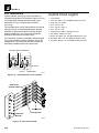
2.3.1
Fastener Rating
Unless otherwise specified, the following values apply for
Grade 5 (PC8.8) nuts and bolts:
Size
Torque
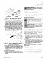
When the vehicle leaves the factory, it is equipped only
with straight thread O-ring fittings. Customer-added
accessories may differ; therefore, consult the manufacturer's product literature for information.
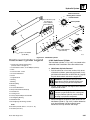
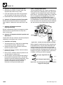
1. Verify that both threads and sealing surfaces are free
of burrs, nicks, scratches, and any foreign material.
2. Lubricate the new O-ring with a light coating of
hydraulic oil.
3. Tighten fitting to the proper torque according to the
following chart:
SAE
Size
lb/ft
Nm
4
22-26
30-35
6
46-54
62-73
Size
Torque
Torque
8
95-105
129-142
10
125-135
170-183
12
165-175
224-237
16
245-255
332-346
20
270-290
366-393
24
365-385
495-522
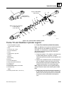
2.3.3
All fasteners (nuts, bolts, washers, etc.) are equal to SAE
Grade 5 (PC8.8) and are plated, unless otherwise specified.
Straight Thread O-ring Fitting
(non-adjustable)
Straight Thread O-ring Fitting
(adjustable)
When the vehicle leaves the factory, it is equipped only
with straight thread O-ring fittings. Customer-added
accessories may differ; therefore, consult the manufacturer's product literature for information.
1. Verify that both mating parts are free of burrs, nicks,
scratches, and any foreign material.
Inch
lb/ft
Nm
mm
Nm
lb/ft
1/4
9
12
6.0
10
7
2. Lubricate the new O-ring with a light coat of hydraulic
oil.
5/16
18
24
8.0
25
18
3. Back off the locknut as far as possible.
3/8
31
42
10.0
50
37
7/16
50
68
--
--
--
1/2
75
102
12.0
80
59
4. Screw the fitting into the port by hand until the
backup washer contacts the face of the port and is
pushed all the way towards the locknut.
9/16
110
150
14.0
130
95
5/8
150
203
16.0
200
146
3/4
250
340
20.0
360
263
7/8
380
515
22.0
510
372
1.0
585
793
24.0
650
475
Model 3606 • Origin 10/99
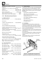
5. To position the fitting, unscrew by the required
amount, but not more than one full turn.
2-3
Section 2
6. Hold the fitting in the desired position and tighten to
the proper torque according to the following chart:
Adjustable Straight-thread O-ring Fitting Torque Chart
SAE
Size
Torque
lb/ft
Nm
4
14.5-17.5
20-24
6
37-43
50-58
8
75-85
102-115
10
115-125
156-170
12
155-165
210-224
16
225-235
305-319
20
260-280
353-380
24
340-360
461-488
Acres
0.4
Hectares (ha)
Ounces (oz)
28
Grams (g)
Pounds (lb)
0.4536 Kilograms (kg)
MASS (weight)
Short tons (2000 lb) 0.9
Metric ton (t)
VOLUME
Teaspoons (tsp)
5
Milliliters (ml)
Tablespoons (Tbsp) 15
Cubic inches
(in3)
Milliliters (ml)
16
Milliliters (ml)
Fluid ounces (fl oz) 30
Milliliters (ml)
Cups (c)
0.24
Liters (l)
Pints (pt)
0.47
Liters (l)
Quarts (qt)
0.95
Liters (l)
Gallons (gal)
3.8
Liters (l)
Cubic feet (ft )
0.03
Cubic meters (m3)
A. Approximate American to Metric Conversions
Cubic yards (yd3)
0.76
Cubic meters (m3)
When this is known Multiply by - - -To Find
AIR PRESSURE
TORQUE (moment of force)
Pounds per square 6.895
inch (psi)
2.3.4
Metric Conversion Factors
Pound/feet (lb/ft)
3
1.356
Newton meters (Nm)
Pound/inches (lb/in) 0.113
Newton meters (Nm)
HYDRAULIC PRESSURE
Pounds per square 0.069
inch (psi)
POWER
Horsepower (hp)
745.7
Watts
1.609
Kilometers per hour
(km/hr; kph)
0.425
To determine degrees Celsius (°C), subtract 32, then
multiply by 0.56; (°F - 32) x 0.56 = °C.
B. Approximate Metric to American Conversions
FUEL CONSUMPTION
Miles per gallon,
US (mpg)
Bars
TEMPERATURE (exact)
SPEED (velocity)
Miles per hour
(mph)
Kilopascals (kPa)
Kilometers per liter (km/l)
[Miles per gallon values are commonly converted to
liters/100 kilometers; mpg (Imperial x l/100 km = 282;
US mpg x l/100 m = 235)]
LENGTH (distance)
When this is known
Multiply by - - -To Find
TORQUE (moment of force)
Newton meters (Nm) 0,738
Pounds/feet (lb/ft)
Newton meters (Nm) 8,85
Pounds/inches (lb/in)
POWER
Inches (in)
25.4
Millimeters (mm)
Watts
Inches (in)
2.5
Centimeters (cm)
SPEED (velocity)
Feet (ft)
30.5
Centimeters (cm)
Feet (ft)
0.305
Meters (m)
Kilometers per hour 0,621
(km/hr; kph)
0,0013 Horsepower (hp)
Miles per hour (mph)
Yards (yd)
0.9
Meters (m)
FUEL CONSUMPTION
Miles (mi)
1.6
Kilometers (km)
Kilometers per liter
(km/l)
Square centimeters (cm2)
[Miles per gallon values are commonly converted to liters/
100 kilometers; mpg (Imperial x l/100 km = 282;
US mpg z l/100 km = 235)]
AREA
Square inches (in2) 6.5
Square feet
(ft2)
Square yards
(yd2)
0.09
Square meters
0.8
Square meters (m2)
Square miles (mi2) 2.6
2-4
(m2)
2,352
Miles per gallon, US (mpg)
Square kilometers (km2)
Model 3606 • Origin 10/99
General Information, Specifications, and Maintenance
LENGTH (distance)
Millimeters (mm)
0,0394 Inches (in)
Centimeters (cm)
0,394
Inches (in)
Meters (m)
3,281
Feet (ft)
Meters (m)
1,1
Yards (yd)
Kilometers (km)
0,621
Miles (mi)
AREA
Square centimeters 0,4
(cm2)
Square inches (in2)
Square meters (m2) 1,1
Square yards (yd2)
0,6
Square miles (mi2)
Square kilometers
(km2)
Hectares (10000 m2) 2,5
Acres
MASS (weight)
Grams (g)
0,035
Ounces (oz)
Kilograms (kg)
2,2
Pounds (lb)
Metric ton (1000 kg) 1,1
(t)
Short tons
VOLUME
Milliliters (ml)
0,03
Fluid ounces (fl oz)
Milliliters (ml)
0,06
Cubic inches (in3)
Liters (l)
2,1
Pints (pt)
Liters (l)
1,06
Quarts (qt)
0,26
Gallons (gal)
Cubic meters (m )
35
Cubic feet (ft3)
Cubic meters (m3)
1,3
Cubic yards (yd3)
0,145
Pounds per square inch
(psi)
Liters (l)
3
AIR PRESSURE
Kilopascals (kPa)
HYDRAULIC PRESSURE
Bars
14,5
Pounds per square inch
(psi)
TEMPERATURE (exact)
To determine degrees Fahrenheit (°F), multiply degrees
Celsius (°C) by 1.8, then add 32; (°C x 1.8) + 32 = °F.
Model 3606 • Origin 10/99
2-5
Section 2
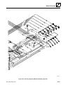
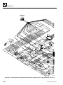
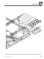
2.4
SPECIFICATIONS
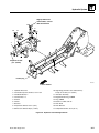
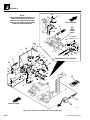
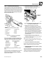
2.4.1
Vehicle Dimensions (Fig. 2-1)
V
M
With Standard 12-ply 13.00-24 Tires
I
Ref. Description
W
A. Length
(without attachment)
221.0" (5613 mm)
B. Width
98.0" (2489 mm)
C. Height (boom lowered)
91.75" (2330 mm)
D. Wheelbase
122.0" (3099 mm)
E. Tread
84.0" (2134 mm)
F. Ground Clearance
17.0" (432 mm)
G. Turning radius, curb to curb
138.0" (3505,2 mm)
H. Turning radius, clearance
180.5" (4584,7 mm)
I. Maximum lift height,
boom extended
36' 2" (11023,6 mm)
J. Maximum lift height,
boom retracted
18' 6" (5638,8 mm)
J
N
0.0
Q
K. Maximum below grade depth,
boom extended
2' 5" (736,6 mm)
L. Maximum reach,
from front of front tires
P
T
0.0
C
R
K O
L
F
D
U
A
24' 8" (7518,4 mm)
M. Maximum reach at maximum lift angle,
boom extended
67.2" (1707 mm)
N. Maximum reach at maximum lift angle,
boom retracted
-26.2" (-665,48 mm)
O. Maximum reach at minimum lift angle,
boom extended
24' 2" (7366 mm)
P. Maximum boom lift angle
68°
Q. Minimum boom lift angle
-3.8°
R. Angle of approach
N/A
S. Angle of departure
33°
B E
G
MS2110
Figure 2–1. Vehicle dimensions with standard tires.
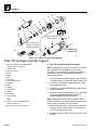
2.4.2
Performance Specifications
Performance criteria is based on full throttle engine
speed unless otherwise specified or not applicable:
A. Travel Speed (standard tires, no load)
First gear
Fork tilt angle:
4-SPEED
3-SPEED
4.3 mph
(6,9 km/hr)
4.2 mph
(6,8 km/hr)
Second gear 9.1 mph
(14,6 km/hr)
9.2 mph
(14,8 km/hr)
Third gear
15.3 mph
(24,6 km/hr)
17.7 mph
(28,5 km/hr)
W. At maximum boom angle down -21.8°
Fourth gear
20.8 mph
(33,5 km/hr)
N/A
Frame tilt angle (not shown):
B. Braking Distance (standard tires, no load)
T. At minimum boom angle up
8.1°
U. At minimum boom angle down -108.3°
V. At maximum boom angle up
2-6
S
80.8°
Right
10.0°
Left
10.0°
4-SPEED
From road speed
to stop
29.0 ft (8,8 m)
3-SPEED
21.4 ft (6,5 m)
Model 3606 • Origin 10/99
General Information, Specifications, and Maintenance
C. Cylinder Times (with no load, at full throttle)
F. Fuel Consumption
Function
Average, depending on load/duty:
2 gal/hr (1,67 Imp gal/hr, or 7,57 l/hr)
Approximate Times, in seconds
Boom extend
12.00
Boom retract
7.00
Boom lift retracted
12.75
Boom lower retracted
10.75
Fork tilt up
4.20
Fork tilt down
3.75
Frame tilt left to right
with boom down
8.50
G. Steering Wheel
Maximum number of turns, lock to lock
3.80 turns
Minimum number of turns, lock to lock
3.20 turns
H. Breakout Force
Frame tilt left to right with boom above 40° and emergency
brake engaged
24.0 to 30.0
Utility bucket (calculated at -24° lip angle, max moment)
15,100 lb (6.855,4 kg).
Frame tilt right to left
with boom down
2.4.3
13.50
Frame tilt right to left with boom above 40° and emergency
brake engaged
24.0 to 30.0
D. Draw Bar Pull
Per SAE drawbar test, 200 ft (61 m) track
4-SPEED
A. Basic Vehicle
Curb Weight
20,195 lbs (9.160 kg)
Operating Load
6,600 lbs (3.000 kg)
B. Working Weight
3-SPEED
Peak drawbar
in 1st gear
at converter stall
(no load)
15,000 lb
(6.810,0 kg), slip
Weights
Machine working weight is figured with 48" carriage, two
48" pallet forks, 25%-full fuel tank, and standard bias ply
tires (no hydrofill):
13,250 lb
(6.015,5 kg), no slip
Peak drawbar
in 1st gear
at converter stall
(rated load)
16,750 lb
13,250 lb
(7.604,5 kg), no slip (6.015,5 kg), no slip
Front Axle
Rear Axle TOTAL
Open Cab
8,390 lb
(3,8 kg)
12,540 lb
(5,6 kg)
20,930 lb
(950 kg)
Closed Cab
N/A
N/A
N/A
C. Attachments
Std 48" carriage with shaft ....................... 456 lb (205 kg)
Std 60" carriage with shaft .................... 526 lb (236,7 kg)
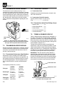
E. Engine Performance
Std 72" carriage with shaft .................... 677 lb (304,6 kg)
Low idle setting for all engines = 1050 +/- 50 RPM
Engine
Model
Displacement
High Idle
Horsepower
Peak
Torque
Perkins
Turbo
1004.4T
243 CID
2600 +/100
108 HP @
2400 rpm
277 lb/ft
@ 1600
rpm
Perkins
Natural/
EPA
1004.42
258 CID
2600 +/100
86 HP
@ 2400
rpm
221 lb/ft
@ 1600
rpm
Cummins
Turbo
4BT3.9
239 CID
2700 +/100
110 HP @
2500 rpm
293 lb/ft
@ 1500
rpm
48" side tilt carriage
with shaft and cylinder.............................. 640 lb (288 kg)
60" side tilt carriage
with shaft and cylinder.............................. 700 lb (315 kg)
72" side tilt carriage
with shaft & cylinder .............................. 770 lb (346,5 kg)
52" swing carriage
with shaft & cylinders ............................ 950 lb (427,5 kg)
72" swing carriage
with shaft and cylinder...................... 1,135 lb (510,75 kg)
Bucket, 1.125 yd3 (0,855 m3) ................... 760 lb (342 kg)
Note: Engine manufacturer’s maximum “high idle” setting
is lockwired and sealed. DO NOT disturb this setting.
Model 3606 • Origin 10/99
Broom, 8 foot (2,44 m) .......................... 1,100 lb (495 kg)
Pallet forks, 2.25 x 4 x 48 (5,7 x 10 x 122 cm),
quantity: 2 ............................................. 312 lb (140,4 kg)
2-7
Section 2
Block forks, 2 x 2 x 48 (5 x 5 x 122 cm)
quantity: 6................................................. 480 lb (216 kg)
Lumber forks, 1.75 x 7 x 60 (4 x 17,8 152,4 cm)
quantity: 2.............................................. 466 lb (209,7 kg)
Auger drive unit ..................................... 285 lb (128,2 kg)
Auger mounting frame................................ 180 lb (81 kg)
Auger (various sizes available)............................... Varies
Auger extension (various sizes available) .............. Varies
C. Tamper Proofing
A tamper-proof means is in place on the following adjustable components prior to machine shipment. This can
either be tamper-proof paint, or a steel tamper-proof cap.
DO NOT attempt to defeat, by-pass or alter any tamperproof device.
• Hoist cylinder counterbalance valves (1)
• Main valve port relief valves (5)
• Extend cylinder counterbalance valves (2)
2.4.4
Miscellaneous Specifications
A. Wheels and Tires
Wheel lug nut torque ............................370 lb/ft (500 Nm)
Air Pressure
13.00-24, 12-ply (minimum) tires ........... 65 psi (448 kPa)
Tire Footprint Area
(area is established under max tip load)
13.00-24, 12-ply tires @ 65 psi (448 kPa),
Vehicle with no load: ............................ 140 in2 (910 cm2)
• Steering relief valve (1)
• Fork cylinder counterbalance valves (2)
• Pilot relief valve (1)
• Main system relief valve (1)
• Park brake relief (1)
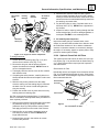
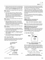
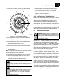
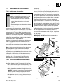
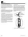
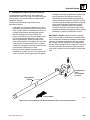
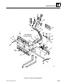
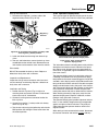
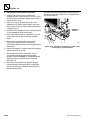
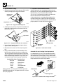
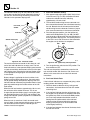
D. Fork Ratings
All approved forks for this vehicle are marked with a
maximum load capacity rating. This rating is stamped on
the left edge of the fork, just below the fork pivot shaft
(Fig. 2–2). The rating is listed in U.S. pounds and based
upon a 24" (610 mm) load center.
13.00-24, 12-ply tires @ 65 psi (448 kPa),
Vehicle with rated load: ................... 165 in2 (1072,5 cm2)
This rating specifies the maximum load capacity that the
individual fork can safely carry at a maximum load center
of 24" (610 mm).
Maximum Ground Pressure
Since forks are always used in multiples, the total rating
of any combination of forks is the sum of their rated
capacity.
Vehicle with no load,
13.00-24 12-ply tires @ 65 psi (448 kPa):
............................................................ 75 psi (516,6 kPa)
Vehicle with 6,600 lb (2.994 kg) load,
13.00-24 12-ply tires @ 65 psi (448 kPa):
............................................................ 85 psi (585,4 kPa)
Other than block forks, use all forks in matched pairs.
Use block forks in matched sets.
Stamped
Fork Rating
Note: Maximum ground pressure at tip = (machine
weight + load) / (foot print area x 2)
Main system relief .............3,500 +/- 100 psi (241,5 Bars)
Load
Center
4000 x 24
B. Valve Relief Settings
in. )
24 mm
0
1
(6
Port relief boom extend ..........3,175 +/- 75 psi (219 Bars)
4000 x 24
Port relief boom hoist ........3,700 +/- 100 psi (255,3 Bars)
Port relief boom retract......3,750 +/- 100 psi (258,8 Bars)
Port relief fork tilt
(both sides) .......................3,700 +/- 100 psi (255,3 Bars)
Pressure-reducing/relieving valve,
stabilizer cylinder........................100 +/- 25 psi (6,9 Bars)
Power steering relief..........2,500 +/- 100 psi (172,5 Bars)
Park brake relief ......................... 550 +/- 50 psi (38 Bars)
2-8
OS0390
Figure 2–2. The stamped fork rating specifies the
maximum load capacity that the individual fork can
safely carry at a maximum load center of 24" (610 mm).
Model 3606 • Origin 10/99
General Information, Specifications, and Maintenance
2.5
2.5.1
FLUIDS, LUBRICANTS AND
CAPACITIES
2.5.2
Axles (Differential Housings) and
Transfer Case
In general, use gear oil with an API classification of GL-5
that meets the requirements of U.S. ordinance specification MIL-L-2105 and MIL-L-2105D, respectively. The oil
should be a 90W, a multi-grade 80W-90, or 80W-140 with
EP properties (80W-90 EP). Products known to meet
these requirements include:
A. Axle and Transfer Case Lubricants
In general, use gear oil that meets the requirements of
U.S. ordinance specification MIL-L-2105C with an API
classification of GL-5. The oil should be a multi-grade
80W90 with EP properties.
Products known to meet these requirements include:
• AMOCO GEAR LUBE 80W90
• ARCO HD 90W GEAR LUBE
• BP TRANS GEAR 80W90
• CATERPILLAR 80W90 EP GL-5
• CHEVRON ULTRA GEAR LUBE 80W90
• CITGO PREMIUM GEAR LUBE 80W90
Wheel Ends
A. Wheel-end Lubricants
• BP TRANS GEAR 80W90
• CHEVRON ULTRA GEAR LUBE 80W90
• CITGO PREMIUM GEAR LUBE 80W90
• MOBIL MOBILUBE HD 80W90
DO NOT add additional friction modifier to factory-filled
wheel ends. All wheel ends are factory-filled by the manufacturer with oil. If a wheel end is drained for service, it
should be refilled with the gear oils listed above.
Note: DO NOT use synthetic oil without the express written consent of the manufacturer.
• CONOCO UGL 80W90
• EXXON GEAR OIL GX80W90
B. Wheel-end Capacity
• FRANKLIN GEAREX AGMA 5 EP GEAR OIL
Wheel end capacity.............. 1.4 qt (44.8 oz, or 1,324 ml)
• KENDALL NS-MP 80W90
• MOBIL MOBILUBE HD 80W90
2.5.3
Lubrication Points (grease fittings)
• MP GEAR LUBE GL-5 80W90
Lubricants
• PENNZOIL 409L 80W90
When lubricating any component via the grease fittings,
use multi-purpose lithium-based grease with EP additives
that meets NLGI Grade-2 specifications. Products known
to meet these requirements include:
• QUAKER STATE HIGH PERFORMANCE 80W90
• QUAKER STATE SYNTHETIC 80W90
• SHELL SPIRAX HD 80W90
• STUART M2C-105A 80W90
• SUNOCO DURO GEAR GL-5, SYNTHETIC
• SUNOCO MULTI-PURPOSE GL-5
• TEXACO DIFFERENTIAL GEAR LUBE 80W90
• TEXACO MULTIGEAR EP 80W90
• UNICAL 76 MP GEAR LUBE-LS
• VALVOLINE
HIGH PERFORMANCE GEAR LUBE 80W90
Note: Use of a premium grade 80W140 gear oil is recommended for operation where the ambient (outside air)
temperature is consistently above 80°F (27°C).
B. Axle and Transfer Case Capacities
• AMOCO AMOLITH EP2
• ARCO LITHOLINE EP2
• BENZ MOLY-SERVICE EP2
• CHEVRON DUROLITH EP2
• CITGO H EP2
• GULF GULFCROWN EP2
• MOBILE MOBILUX EP2
• SHELL ALVANIA EP2
• SUN PRESTIGE 742EP
• TEXACO MULTIFAX EP2
Note: Refer to section 2.12.2 Maintenance Schedule
and Checklist for lubrication intervals and grease fitting
locations.
Axles (differential housings) ............................ 18 qt (17 l)
Transfer case ................................................. 1.5 qt (1,4 l)
Model 3606 • Origin 10/99
2-9
Section 2
2.5.4
Hydraulic System
2.5.5
Engine
A. Hydraulic Fluids
A. Engine Fluids and Lubricants
The hydraulic system is factory filled with ISO Grade 46
anti-wear hydraulic oil. When filling the hydraulic system,
use an anti-wear hydraulic oil meeting ISO Grade 46 with
-40°F (-40°C) pour point/ASTM viscosity SUS 215 at
100°F (38°C), or a 10W motor oil that meets the requirements of U.S. ordinance specification MIL-L-2104C.
Products known to meet these requirements include:
1. Engine oil:
Diesel Engine Oil, SAE 10W-30, or 15W40
• BENZ PETRAULIC 46-7C
In general, use a premium-quality 10W-30 diesel engine
(motor) oil. Additives are not necessary. For most climates,
use 15W40 motor oil that meets API, CD or CE (severe
duty diesel engine) specifications. In cold climates where
ambient (outside air) temperatures are consistently below
32°F (0°C), 10W30 motor oil can be used; however, continuous use of low viscosity oil may cause premature
engine wear.
• CASTROL AGRICASTROL HDD
2. Cooling system (engine coolant):
• CASTROL/DEUSOL CRD
• CHEVRON AW HYDRAULIC OIL 46
In general, use a 50/50-mix of premium-quality ethylene
glycol (commonly referred to as “anti-freeze/anti-boilover”)
and water. Additives are not necessary.
• CITGO PACEMAKER XD-46
3. Fuel:
• ESSO ESSOLUBE D-3HP
In general, use No. 2 diesel fuel. From November 15 to
March 15 when operating in cooler climates where ambient (outside air) temperatures are consistently at or
below 32°F (0°C), use a 50/50 mix of #1 and #2 diesel
fuels. Use good quality diesel fuel and change the fuel
filter regularly. Additives are not necessary.
• AMOCO RYKON 46
• ARCO DURO AW S-215
• ESSO ESSOLUBE XD-3
• GULF HARMONY 46 AW
• ISO-46 HYDRAULIC OIL
• MOBIL DTE-25
• SAE 10W MOTOR OIL
• SHELL RIMULA CT
• SHELL RIMULA TX
• SHELL RIMULA X
• SHELL TULLUS 46
• SUN SUNVIS 821 WR
• TEXACO RANDO HD 46
Note: For -30°F to +70°F (-34°C to 21°C), 5W20 motor
oil with -50°F (-45°C) pour point can be substituted. However, above 70°F (21°C), hydraulic system oil must be
changed to ISO-46 hydraulic oil or SAE 10W motor oil.
B. Hydraulic System Capacity
System capacity ................................... 59.5 gal (225,2 l)
Reservoir capacity ................................ 32.2 gal (121,9 l)
B. Engine Capacities
1. Engine oil capacity:
TOTAL CAPACITY
WITH FILTER CHANGE
FILTER
CAPACITY
Cummins Turbo ......... 11.6 qt (11,0 l)............ 1.3 qt (1,2 l)
Perkins Turbo ............ 9.0 qt (8,5 l)............... 1.5 qt (1,5 l)
Perkins Natural.......... 9.0 qt (8,5 l)............... 1.5 qt (1,5 l)
2. Cooling system capacity (w/o heater):
Cummins Turbo ......... 5.0 gal (18,9 l)
Perkins Turbo ............ 5.0 gal (18,9 l)
Perkins Natural.......... 5.0 gal (18,9 l)
Coolant system overflow bottle capacity:
CAPACITY
W/O HEATER
CAPACITY
W/ HEATER
Overflow bottle .......... 3.0 qt (2,8 l)............... 3.0 qt (2,8 l)
3. Fuel tank capacity:
Total capacity ............ 35.1 gal (132,8 l)
Usable capacity......... 33.6 gal (127,2 l)
2-10
Model 3606 • Origin 10/99
General Information, Specifications, and Maintenance
2.5.6
Transmission
A. Transmission Fluid
RECOMMENDED LUBRICANTS FOR CLARK-HURTH
T12000 POWER SHIFTED TRANSMISSION
Vehicle transmissions are factory filled with 10W motor
oil. Any suitable 10W motor oil, which meets the requirements of U.S. ordinance specification MIL-L-2104C, can
be used. Products known to meet these requirements
include:
•
•
•
•
•
•
•
•
•
ARCO TRACTOR FLUID or equivalent
CASTROL AGRICASTROL HDD
CASTROL/DEUSOL CRD
ESSO ESSOLUBE D-3HP
ESSO ESSOLUBE XD-3
SAE 10W MOTOR OIL
SHELL RIMULA CT
SHELL RIMULA TX
SHELL RIMULA X
In general, use any approved 10W or 5W20 motor oil
(depending on ambient temperatures; see information
below), Dexron* or Dexron II D*, or an anti-wear hydraulic
oil meeting ISO Grade 46 specifications with a -40°F
(-40°C) pour point/ASTM viscosity SUS 215 at 100°F
(38°C).
For -30°F to +120°F (-34°C to 49°C), Dexron* II transmission fluid with a -50°F pour point may be substituted.
5W20 motor oil may be substituted for use with temperature conditions of -30°F to 70°F (-34°C to 21°C) only.
Products known to meet these requirements include:
•
•
•
•
•
•
•
•
•
•
•
AMOCO RYKON 46
ARCO DURO AW S-215
BENZ PETRAULIC 46-7C
CHEVRON AW HYDRAULIC OIL 46
CITGO PACEMAKER XD-46 or equivalent
GULF HARMONY 46
ISO-46 HYDRAULIC OIL
MOBIL DTE-25
SHELL TULLUS 46
SUN SUNVIS 821 WR
TEXACO RANDO HD 46
If anti-wear hydraulic oil as specified above is not available,
a suitable tractor fluid may be substituted which meets
the requirements of any of the following specifications:
•
•
•
•
•
•
3
150
140
130
120
110
100
90
80
70
60
50
40
30
20
10
0
-10
-20
-30
-40
-50
-60
Farenheit
60
50
Temperature Range "3"
40
If using Dexron*,
Use ONLY Dexron*
or Dexron II D*
See NOTE Below
30
20
10
0
-10
-20
-30
-40
-50
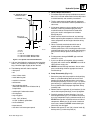
Celsius
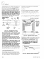
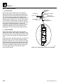
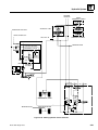
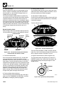
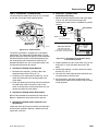
Chart 2-1. Transmission fluid temperature range.
PREFERRED OIL VISCOSITY: Select the highest viscosity compatible with prevailing ambient temperatures
and the oil application information listed under Section
2.5.6 A. Transmission Fluid.
The Clark Hurth T12000 modulated shift transmission
used in this vehicle should use ONLY C-3 or Temperature Range 3 transmission fluids, Dexron* or Dexron II
D*.
Note: Dexron II D* is not compatible with graphitic clutch
plate friction material UNLESS IT MEETS THE
APPROVED C-3 SPECIFICATIONS.
*Dexron and Dexron II D are registered trademarks of General
Motors Corporation.
B. Transmission Capacity
Capacity w/ filter change ................. 3.4 gal (12,9 l)
Filter .................................................... 1.5 qt (1,4 l)
ARCO TRACTOR FLUID or equivalent
DETROIT DIESEL C-3
FORD TRACTOR M2C134B
JOHN DEERE J20A
TEXACO TDH OIL
WHITE FARM Q1826
Model 3606 • Origin 10/99
2-11
Section 2
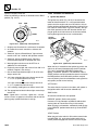
2.5.7
Drive Shaft Splines
B. Anti-corrosion Need Areas
IMPORTANT: DO NOT disassemble any of the drive
shafts (see Section 6 Transfer Case of this manual for
information covering drive shafts and U-joints). To help
ensure optimum performance, the drive shaft assemblies
are specially balanced as a unit at the factory. When servicing any flange yoke, slip yoke or drive shaft tube, order
a complete assembly. Refer to the parts manual for
ordering information.
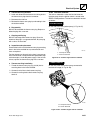
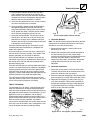
Coat all unplated pins and all bores for cylinder pins, attachment pivot pins, chain sheave pins, the quick-attach lock
pin, and all quick-attach lock pin bores. On the boom,
coat the fork shaft and unpainted boom slide pathways.
Respective of the above statement, should it become
necessary to coat the transmission input drive shaft
splines, use molybdenum disulfide grease. Molybdenum
disulfide grease specifically formulated for this purpose is
marketed by several manufacturers under various
names, including:
Battery Type ................ 12Vdc, Negative (-) ground/earth,
Maintenance Free
Aldrich Chemical Co., Inc.
Product name: Aldrich MOLYBDENUM (IV) SULFIDE,
Catalog Number 23,484-2
Package Size: 5 g (0.175 oz)
100 g (3.5 oz)
500 g (17.5 oz)
Contact:
Aldrich Chemical Co., Inc.
P.O. Box 335
Milwaukee, Wisconsin 53201 USA
Telephone: (414) 273-3850
Alternator Rating .................................................65 amps
DOW CORNING INC.
Product name: MOLYKOTE® 77 Paste
Contact:
Dow Corning Corporate Center
P.O. Box 994
Midland, MI 48686-0994
Telephone: (517) 496-4400
• Neutral Sense .......................................................... 7.5
2.5.8
• Steering Solenoids ................................................... 7.5
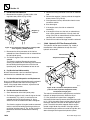
General Anti-corrosion
A. Anti-corrosion Compound
For general anti-corrosion protection, use a wax film rust
inhibitor that provides a protective film two ten-thousandths
of an inch (0.0002", or 0,00005 mm) thick. One such rust
inhibitor that is specifically formulated for this purpose is
LPS 3. It is marketed by:
LPS Laboratories, Inc.
4647 Hugh Howell Rd.
Tucker GA 30085-5052
Phone: 1-800-241-8334
Fax: (770) 493-9206
Note: Anti-corrosion protection is especially important in
frame and stabilizer cylinder pin support bores for protection from fretting corrosion wear.
2.5.9
Electrical
A. Basic Ratings
Battery Rating ..........................1,000 cold cranking amps
@ 0°F (-18°C)
Number of Batteries ............................................. One (1)
B. Fuse Ratings, amps
• Main (S/N 8249 and Before) ..................................... 40
(S/N 8250 and After) ........................................ 30
• Cold Start (Optional) ................................................. 15
• Logic Panel .............................................................. 7.5
• Display Panel ........................................................... 7.5
• Fuel Shutoff ............................................................. 7.5
• Neutral Relay/Starter ............................................... 7.5
• Hourmeter ................................................................ 7.5
• Horn ......................................................................... 7.5
• Stabil-TRAK ............................................................. 7.5
• Stabilizer Lock Relay ................................................ 7.5
• Park Brake Sense Relay .......................................... 7.5
• Transmission Solenoids ........................................... 7.5
• Transmission Relay (without Closed Cab Option)..... 7.5
• Transmission Relay (with Closed Cab Option)........... 15
• Switch Lamps (Optional) .......................................... 7.5
• Closed Cab Option - Front Wiper Motor .................. 7.5
• Closed Cab Option - Skylight Wiper Motor .............. 7.5
• Closed Cab Option - Rear Wiper Motor ................... 7.5
• Closed Cab Option - Blower Motor ........................... 25
• Closed Cab Option - Power WIndow Motor .............. 30
• Closed Cab Option - Power Accessories Relay ........ 40
• Closed Cab Option - Power Window Motor Relay .... 40
• Light Package Option - Circuit A ............................... 20
• Light Package Option - Circuit B ............................... 20
2-12
Model 3606 • Origin 10/99
General Information, Specifications, and Maintenance
2.5.10 Paint
C. White Paint
Unless otherwise specified, paint components as indicated in the following sections.
Durable, premium white paint is available in both a convenient 16-ounce (480 ml) spray can for touch-ups, and
in a production-sized one gallon (3,8 l) container for
extensive repainting. Consult the current Sky Trak Model
3606 PARTS MANUAL for the applicable part number
and ordering information.
A. Orange Paint
Durable, premium Sky Trak orange paint is available in
both a convenient 16-ounce (480 ml) spray can for touchups, and in a production-sized one gallon (3,8 l) container
for extensive repainting. Consult the current Sky Trak
Model 3606 PARTS MANUAL for the applicable part
number and ordering information. Use orange paint on all
vehicle components except as specified in paragraphs
2.5.10 A, B, C and D.
• Boom Extend Cylinder
• Extend Cylinder Mount Bracket (some models)
D. Gray Paint
The following parts must be painted dark gray (Ref.: Sky
Trak Color Chip 8528102):
B. Black Paint
• Wheels
Durable, premium black paint is available in both a convenient 16-ounce (480 ml) spray can for touch-ups, and in a
production-sized one gallon (3,8 l) container for extensive
repainting. Consult the current Sky Trak Model 3606
PARTS MANUAL for the applicable part number and
ordering information.
• Engine mount/Hyd. tank
• Boom Angle Indicator Pointer
• Wheels (some models)
• Brake Pedal
• Counterweight
• Cab Mount
Durable, premium gray paint is available in both a convenient 16-ounce (480 ml) spray can for touch-ups, and in a
production-sized one gallon (3,8 l) container for extensive
repainting. Consult the current Sky Trak Model 3606
PARTS MANUAL for the applicable part number and
ordering information.
• Radiator
• Wheels (some models)
• Seat Adapter Plate
• Fuel Tank Cradle
• Radiator Shroud
• Hydraulic Fluid Reservoir
• Transmission Oil Cooler
• Battery Cover Panel
• Axles
• Drive Shafts
2.5.11 Thread Locking Compound
• Drop Box
• Forks
For general thread-locking purposes, Loctite® products,
manufactured by Loctite Corporation, are recommended.
• Mirrors and Mirror Brackets
Contact:
• Air Cleaner
• Steering Column
Loctite Corporation
1001 Trout Brook Crossing
Rocky Hill, CT 06067 USA
Phone: 1-800-LOCTITE (1-800-562-8483)
FAX: (860) 571-2460
Internet: http://www.loctite.com
Loctite® is a registered trademark of Loctite Corporation.
Model 3606 • Origin 10/99
2-13
Section 2
2.6
CLEANING
Dirt and abrasive dust reduce the efficient working life of
parts and systems, and lead to the costly replacement of
components. To help increase the service life of parts,
clean the exterior of all parts before beginning any repairs.
2. Hoses must remain in good condition. Obvious signs
of external hose wear or hydraulic fluid leaking or
weeping indicates the need to replace the hose
assembly. If in doubt, replace the hose.
3. Replace if any of the following conditions exist:
• Ballooning (replace hose immediately!)
Use cleaning fluids and solvents suitable for cleaning
parts that do not create safety hazards. Certain types of
cleaning fluids can cause skin irritation and damage to
components (such as rubber, electrical parts, etc.).
Servicing the hydraulic system in particular requires
cleanliness.
Follow these precautions before attempting to service
any hydraulic component:
• Kinking, crushing, stretching or deforming
• Concealed corrosion of wire reinforcement
• Chafed outer cover
2.8.2
Hose and Tube Installation
1. Flush hose and tube assemblies with a solvent
compatible with hose materials. Blow excess solvent
away with shop air.
1. When installing a new hose, loosely connect each
end and verify that the hose takes up the designed
position before tightening the connection completely.
Tighten clamps sufficiently to hold the hose without
crushing it, and to prevent movement and chafing.
2. Cap hydraulic fittings, hoses and tube assemblies,
and protect threads until time of installation. Clean up
any hydraulic fluid spillage immediately.
2. If a hose is replaced on a moving part, move the part
through its entire range of motion to verify that the
hose will not incur damage. Adjust as necessary.
3. Flush hydraulic reservoir, fuel tank, and gear housing
with a suitable solvent to remove paint, metal chips,
etc.
3. When installing any hose, verify that it does not
become kinked or twisted.
4. Protect hydraulic system components from airborne
contaminants. Plug all cylinder, valve, reservoir, tank
and pump openings until time of installation.
5. Use clean, filtered oil when filling the system. Maintain
the hydraulic system at a minimum cleanliness level
of ISO code 18/15-particle ration count.
4. NEVER allow freely-moving or unsupported hoses to
contact each other or a related work surface. Such
contact causes chafing and reduces hose life.
2.9
BEARINGS
2.9.1
Bearing Removal
ALWAYS use the correct tool when removing or replacing any part or performing any service.
1. NEVER remove bearings unless absolutely
necessary! Always use the recommended puller to
reduce the risk of bearing or related component
damage.
Replace O-rings, seals, and gaskets whenever they are
disturbed. NEVER mix new and old seals or O-rings,
regardless of apparent visual condition. Always lubricate
new seals and O-rings with hydraulic oil before installation.
2. When bearings or bushings are removed, verify that
the bearing or bushing is free from discoloration,
nicks, scuffing, and signs of overheating. If in doubt,
replace the bearing or bushing.
2.7
REPLACEMENT
2.8
HOSES AND TUBES
2.8.1
Hose and Tube Inspection
1. Damaged, dented, crushed, or leaking hose and tube
fittings restrict oil flow and the operation of the
system being served. Fittings showing signs of
movement from their original position have failed and
must be replaced. ALWAYS replace the entire hose
or tube assembly if the fittings are damaged.
2-14
2.9.2
Bearing Cleaning
Wear safety glasses. Clean bearings acceptable for service in a suitable solvent. NEVER spin-dry a bearing with
compressed air; this can cause metal-to-metal contact
and bearing damage. Compressed air can also cause a
bearing to come apart. After cleaning a bearing, immerse
it in clean lubricating oil until needed.
Model 3606 • Origin 10/99
General Information, Specifications, and Maintenance
2.9.3
Bearing Installation
1. Always install bearings carefully to help avoid
damaging their delicate surfaces.
2. Install bearings using one of the following methods:
4. Purge the hydraulic system of air by operating all
vehicle functions through their entire range of motion
several times.
5. Check for proper operation of all components.
• PRESS FIT for installation on rotating parts such
as shafts and gears;
6. Retract all cylinders fully. Turn the engine OFF and
check the hydraulic reservoir level. Recheck the level
when the hydraulic oil is cold.
• PUSH FIT into static locations such as reduction
gear housings.
7. Replace the hydraulic filter if required.
3. Always install the bearing into the rotating part first
whenever possible.
2.11.2 After Electrical/Electronic Component
Service
4. Use a press or the proper installation tools when
installing a bearing or bushing.
1. Check the torque of all fasteners securing replaced
electrical/electronic components.
5. In the absence of a press or proper installation tools,
carefully heat the casing and/or bearing in hot oil to
assist in the installation.
2. Check wiring connections to components.
2.10
PRESSURE TESTING AND
ADJUSTMENT
3. Verify that wiring components are dry and free of
moisture.
4. Check connectors for broken, frayed, or loose wires.
5. Check for brittle or frayed wire shielding.
Prior to pressure testing or adjustment, verify that all
hoses and tubes are in good condition and that all fittings
are tight.
6. Connect the negative (-) battery cable terminal to the
battery; if it is disconnected.
Use pressure gauges with the proper ranges and ratings
to measure the specified pressures.
8. Recalibrate sensors as required.
Use correct test procedures to help prevent personal
injury, damage to the system or test equipment.
Verify that the hydraulic oil is at proper operating temperature, 80°-120°F (27°-49°C), before adjusting the pressure
reducing valve, or relief valves. If necessary, operate the
vehicle to raise the oil temperature. In the absence of a
temperature gauge, the oil temperature can be checked
by placing a hand against the side or the bottom of the
reservoir; if the tank is too hot to keep the hand in contact
with it, the oil temperature should be within the proper
range.
2.11
AFTER SERVICE STARTUP AND
CHECKS
2.11.1 After Service Startup
Note: Refer to the owners/operators manual for engine
cold-start procedures.
1. Check fluid levels.
2. Connect the negative (-) battery cable to the battery if
it is disconnected.
7. Start the engine and bleed the hydraulic system of air.
9. Check the operation of the replaced component(s).
2.11.3 After Hydraulic Component Service
1. Check torque of fasteners on replaced components.
2. Check that hoses and tubes are properly attached,
positioned, and tightly connected.
3. If a hydraulic component failed and contaminated the
system, flush the system, clean the hydraulic oil
reservoir (tank), and replace the hydraulic oil filter.
4. After normal hydraulic component maintenance,
check the hydraulic fluid level and add fluid as
required.
5. Start engine and bleed hydraulic system of air.
Operate all boom functions through their full range of
motion several times. Cycle the hoist and extend
cylinders to bleed air from the system. Visually check
for leaks.
6. Recalibrate sensors as required.
7. Check operation of all systems in the hydraulic circuit
by operating the controls through all functions several
times.
3. Start and idle engine. Check for leaks from hydraulic
components, engine, axles, transmission, brakes and
reservoirs or tanks. Check the levels of all fluids and
lubricants.
Model 3606 • Origin 10/99
2-15
Section 2
2.11.4 After Brake System Service
1. Check the oil level in the axle and replenish with SAE
80W90 or SAE 80W140 oil as required.
2. Bleed the brakes.
3. Check brake pressure.
4. Check brake operation.
2.11.5 After Fuel System Service
12. Run engine for two minutes at idle to help prime the
torque converter and transmission lines.
13. Recheck the level of fluid in the transmission with the
engine running at idle.
14. Add ISO 46 10W motor oil as necessary to bring the
fluid level up until it begins to run freely from the
UPPER oil level check plug hole. Install the oil level
plug. Recheck the oil level when it reaches operating
temperature (180-200°F, or 83-94°C).
2. Bleed fuel system.
15. Recheck all drain plugs, lines, connections, etc., for
leaks and tighten where necessary.
3. Fill fuel tank with fresh, clean fuel, as required.
2.11.7 After Tire and Wheel Service
1. Drain and flush fuel tank; if it was contaminated.
2.11.6 After Transmission Service or
Replacement
1. Check transmission oil level and add 10W motor oil
as required. In general, use an anti-wear hydraulic oil
meeting ISO Grade 46 with -40°F (-40°C) pour point/
ASTM viscosity SUS 215 at 100°F (38°C) or other
lubricant that meets these specifications (refer to
Section 2.5.6 Transmission for information on
transmission lubricants).
1. Check air pressure.
2. Check wheel nut torque. Tighten to 370 lb/ft (500 Nm).
2.11.8 After Engine Service
Consult the qualified service agent (manufacturer’s representative and/or service manual) for proper procedures
before engine startup.
2.11.9 After Boom Service
2. Replace transmission filter.
1. Check wear pads.
3. Check torque on drive shaft yoke retaining bolts.
Tighten these M12 bolts to 156 lb/ft (212 Nm).
2. Check chain tension adjustment.
4. Refer to the Clark-Hurth 12000 transmission
maintenance manual for servicing the transmission
after overhaul or repair.
5. Wear suitable eye protection. When an overhauled or
repaired transmission is installed, thoroughly clean
the oil cooler lines to and from the transmission.
6. Drain and flush the entire system.
7. Disconnect and clean all transmission lines. When
possible, remove transmissions lines from the vehicle
for cleaning.
3. Apply grease at all lubrication points (grease fittings).
4. Check for proper operation by operating all boom
functions through their full range of motion several
times.
2.11.10 After Axle Service
1. Check fluid levels.
2. Check torque on drive shaft flange yoke retaining
bolts. Tighten these M12 bolts to 156 lb/ft (212 Nm).
3. Check wheel nut torque. Tighten to 370 lb/ft (500 Nm).
8. Thoroughly clean transmission filter screens and
cases, and replace transmission filter elements.
4. Check toe-in if required.
9. “Back flush” the transmission oil cooler with oil and
compressed air until all foreign material is removed.
Flushing in direction of normal oil flow does not
adequately clean the cooler. If needed, remove the
transmission oil cooler assembly from the vehicle.
DO NOT use flushing compounds for cleaning
purposes.
6. Refer to the axle manufacturer’s maintenance
manual for further information.
5. Apply grease at all lubrication points (grease fittings).
10. Reassemble all components and fill the transmission
with clean, fresh anti-wear ISO Grade 46 or 10W
motor oil through the filler opening until oil comes up
to the FULL port on the transmission housing.
11. Remove UPPER check plug, fill until oil runs from
UPPER oil hole. Replace filler and level plug.
2-16
Model 3606 • Origin 10/99
General Information, Specifications, and Maintenance
2.12
2.12.1 Maintenance Schedule and Checklist
MAINTENANCE INSTRUCTIONS
Maintenance Introduction
A. 10 Hour Intervals
WARNING: DO NOT perform service or maintenance on the vehicle with the engine running.
Contact with moving parts can cause serious
injury or death.
10
This section contains a routine equipment checklist and a
maintenance schedule and checklist with references to
pertinent procedures and instructions. To help prevent
problems before they occur, follow the maintenance
schedule.
Note: Lubrication and Maintenance Chart decals are
located inside the engine compartment cover (Fig. 2–3).
These decals contain a general maintenance schedule
that should be followed to maintain the vehicle in good
operating condition. The same schedule information is
presented in this manual, except that it contains a more
detailed account of how to perform these specific maintenance operations.
H20
Drain
Fuel/Water
Separator
Check
Engine
Coolant
Level
Check
Transmission
Oil
Level
Check
Tire
Pressure
Check
Engine
Oil
Level
Check
Hydraulic
Oil
Level
Check
Boom Wear
Pads
MS0530
Figure 2–4. Ten-hour interval maintenance schedule
and checklist.
At ten hour intervals, perform the following:
• Drain the fuel/water separator (see 2.12.7).
Lubrication chart
• Check the engine coolant level (see 2.12.5).
• Check the engine oil level (see 2.12.6).
Maintenance chart
• Check the hydraulic reservoir oil level (see 2.12.9).
• Check the transmission oil level (see 2.12.10).
• Check the air pressure in the tires (see 2.12.14).
• Check boom wear pad thickness (see 2.12.2).
B. At First 50 Hours of Use
50
Change Engine
Oil and Filter
OS1170
Change
Transmission
Filter
Change
Hydraulic
Filter
Change
Transfer
Case Oil
Figure 2–3. Lubrication and maintenance charts are
located inside the engine cover.
Change
Axle Oil
Change
Wheel End Oil
MS1340
Figure 2–5. First 50 hour interval
maintenance schedule and checklist.
When the vehicle completes its first 50 hours of use,
perform the following:
• Change the engine oil and filter (see 2.12.6 C).
• Change the transmission filter (see 2.12.10).
• Change the hydraulic filter (see 2.12.9).
• Change the transfer case oil (see 2.12.13).
• Change the axle oil (see 2.12.11).
• Change the wheel end oil (see 2.12.12).
Model 3606 • Origin 10/99
2-17
Section 2
C. 250 Hour Intervals
(2)
PLACES
250
A
Change Engine
Oil and Filter
(Cummins)
Check
Transfer Case
Oil Level
C
Check
Axle
Oil Level
F
A
2
(2)
PLACES
D
E
E
Check
Wheel End
Oil Level
3
A
Apply Multi-Purpose
Grease (MPG) At
All Lubrication Points
1
A
A
4
E
E
H
MS1350
Figure 2–6. Two-hundred-fifty hour interval maintenance
schedule and checklist.
B
B B
B
B B
At 250 hour intervals, perform the following:
H
• On a unit equipped with a Cummins engine, change
the engine oil and filter (see 2.12.6).
• Check the transfer case oil level (see 2.12.13).
B
B
B
VIEW IN DIRECTION
VIEW IN DIRECTION OF ARROW
1
OF ARROW
2
• Check the axle oil level (see 2.12.11).
• Check the wheel end oil level (see 2.12.12).
• Apply multi-purpose grease at all lubrication points
(Fig. 2–7). Lubricate the following components via
the grease fittings with a multi-purpose, lithiumbased grease every 250 hours (remove all excess
grease):
G
G
G
A. Hydraulic cylinder pins ..................................7 points
G
VIEW IN DIRECTION OF ARROWS
3
4
B. Drive shaft slip joints and universal joints......9 points
OS0561
Figure 2–7. Sky Trak Model 3606
lubrication points.
C. Boom pivot pin ..............................................2 points
D. Carriage Quick Attach pivot pin.....................2 points
E. Axle trunnion pivot pins .................................4 points
F. Boom attachments .......................................All points
G. Axle steering knuckles ..................................8 points
H. Tilt cylinder pivot pins....................................2 points
Note: Shorten the lubrication interval on all lubrication
points when operating under severe conditions.
D. 500 Hour Intervals
500
Change
Air
Filter
Change
Fuel
Filter
Change Engine
Oil and Filter
(Perkins)
MS1360
Figure 2–8. Five-hundred hour interval maintenance
schedule and checklist.
At 500 hour intervals, perform the following:
• Change the air filter (see 2.12.3).
• Change the fuel filter (see 2.12.7).
• On a unit equipped with a Perkins engine, change
the engine oil and filter (see 2.12.6).
2-18
Model 3606 • Origin 10/99
General Information, Specifications, and Maintenance
E. 1,000 Hour Intervals
Angled-cut
Wear Pad
Indicator
1000
Check
Boom Chain
Tension
Change
Transfer
Case Oil
Check
Fan
Belt
Change
Transmission
Oil and Filter
Change
Axle Oil
Metal
Insert
Wear
Pad
Change
Hydraulic
Oil and Filter
0.625"
(15,9 mm)
Change
Wheel End Oil
MS1370
Figure 2–9. One-thousand-hour interval maintenance
schedule and checklist.
0.25"
(6,4 mm)
Boom
Wear Pad
OS1230
Plate
Spacer
Figure 2–11. Inspect boom wear pads for excessive wear.
• Change the hydraulic oil and filter (see 2.12.9).
The boom wear pads that are under the most stress from
weight of the load will also wear faster than other pads.
For example, the lower pads at the front of the boom are
under much more stress than the pads attached at the
top front or sides of the boom. Consequently, the lower
pads will require service more often.
• Change the transfer case oil (see 2.12.13).
B. Boom Wear Pad Replacement
At 1,000 hour intervals, perform the following:
• Check boom chain tension (see 2.12.17).
• Check the fan belt (see 2.12.8).
• Change the transmission oil and filter (see 2.12.10).
• Change the axle oil (see 2.12.11).
Each boom wear pad is manufactured with a convenient
wear pad indicator. This is the angled cut at each end of
all boom wear pads (Fig. 2–11). The total thickness of a
new boom wear pad is 0.625 inch (15,9 mm). The angled
cut will provide a total wear thickness of 0.25 inch (6,4 mm).
This will leave approximately 0.375 inch (9,5 mm) of total
unused base material.
• Change the wheel end oil (see 2.12.12).
F. 2,000 Hour Intervals
2000
Change
Engine
Coolant
MS1380
Figure 2–10. Two-thousand hour interval maintenance
schedule and checklist.
At 2,000 hour intervals, perform the following:
The pads must NEVER be worn past the angled cut indicator, or the metal pad insert that holds the pads in place
will begin to wear into the boom pad sliding surfaces.
Pads worn past this point will gouge the boom surfaces,
resulting in premature wear of any new boom wear pads
installed, and requiring eventual, expensive replacement
of the boom. Replacement of boom wear pads must be
performed when the boom wear pads indicate.
• Change the engine coolant (see 2.12.5).
C. Boom Wear Pad Lubrication
2.12.2 Boom Wear Pad Maintenance
A. Boom Wear Pad Check
Daily, and every 10 hours of engine operation, visually
inspect the boom wear pads between the boom sections
at the rear and front of the boom for excessive wear
(Fig. 2–11).
The average expected service life of boom wear pads
varies depending on the particular location of each wear
pad within the boom, vehicle use, operating conditions,
and the load weight.
If load weights are at or near maximum capacity, or if the
vehicle is operating in very dirty or dusty conditions, the
boom wear pads will wear at a much faster rate.
Model 3606 • Origin 10/99
IMPORTANT: The boom has been factory lubricated for
proper wear pad break-in and will normally not require
further lubrication. However, after replacing any wear
pad(s), or after prolonged periods of inoperation, light
lubrication of the boom wear surfaces with a rust inhibitor/
lubricant such as LPS 3 or equivalent is recommended to
keep the boom wear surfaces lubricated properly. Light
lubrication of the boom wear surfaces is also recommended
in salt air climates, and when the vehicle is stored, to help
prevent rusting. LPS 3 is marketed by:
LPS Laboratories, Inc.
4647 Hugh Howell Rd.
Tucker GA 30085-5052
Phone: 1-800-241-8334
Fax: (770) 493-9206
2-19
Section 2
2.12.3 Air Cleaner
B. Air Cleaner Element: Change or Clean
A. Engine Air Filter Restriction Warning Indicator
500
1
2
3
F
D
4
MS2180
Figure 2–14. Change or clean the air filter element.
P
N
As indicated by the air cleaner restriction indicator, and/or
every 500 hours, change or clean the air cleaner element.
R
Early Production
OS0790
Engine Air Filter Restriction
Warning Indicator
Outer Primary Element
All air cleaner manufacturers agree that attempting to
clean or wash an element increases the chance for element damage. Consider the value of cleaning an element
against the risks that could lead to engine damage.
Adopt the policy that all elements should be replaced
with new and not cleaned.
Current Production
Engine Air Filter Restriction
Warning Indicator
OS0222
Figure 2–12. Engine air filter restriction warning indicator.
The operator’s display panel includes an indicator light
(Fig. 2–13) that illuminates to alert the operator when
restricted air flow to the engine is sensed. This indicates
that the air filter needs servicing. NEVER operate the
vehicle without the air cleaner assembly and both filters
in place.
Air Cleaner Cover
Careful cleaning or washing, if done correctly, can extend
the life of an element. Each time an element is cleaned,
the dirt-holding capacity is reduced and the risk of dirt
reaching the clean side of the filter is increased. Filters
should NEVER be washed more than six times or
retained for more than one year's service, whichever
comes first.
If an element is washed, use a non-sudsing detergent
that dissolves combustion residues without damaging the
filter media. One such detergent that is specifically
formulated for this purpose is FM 1400. This cleaner
contains biodegradable synthetic detergents and is
environmentally safe. FM 1400 is marketed by:
Filter Service Corp.
2105 W. Apache
Farmington, New Mexico 87401
Telephone: (505) 326-1127
Air Cleaner
Retaining
Clips
Inner Safety Element
Vactuator
Valve
An inner safety element (Fig. 2–15) should NEVER be
washed or reused. ALWAYS install a new element.
Replace safety elements after every third primary element
change. DO NOT remove a safety element until the
inside of the air cleaner canister is thoroughly cleaned.
This will help prevent dirt that could damage the engine
from entering the induction manifold.
IMPORTANT: NEVER run the engine with only the
safety element installed.
OS0440
Figure 2–13. Location of engine air cleaner components.
2-20
Model 3606 • Origin 10/99
General Information, Specifications, and Maintenance
Air Cleaner
Cover
Primary
Element
Safety
Element
Air Cleaner
Element
4. Rinse the filter from the inside out with a gentle
stream of water [less than 40 psi (2,8 kPa), without
nozzle] to remove all dirt and suds. If the inside of the
element has been contaminated with dirty water from
the soaking, rinse both sides.
5. Dry the filter before re-using. Circulate warm air at
less than 160°F (57°C). DO NOT use a light bulb to
dry the filter.
6. Inspect for holes or tears by looking through the filter
toward a bright light. Check for damaged gaskets or
metal parts. DO NOT re-use a damaged filter.
C. Air Intake System-Inspection
Vactuator
Valve (ref.)
OS0450
Inspect the intake piping for cracked hoses, loose
clamps, or punctures that can allow dirt or debris to enter
the combustion chamber. If dirt or debris is allowed to
enter the combustion chamber, it can severely damage
the engine. If necessary, tighten or replace parts to help
prevent air intake system leakage.
Figure 2–15. Engine air cleaner components.
To change elements:
1. Unlatch the three retaining clips (Fig. 2–13) and
remove the air cleaner cover (Fig. 2–15).
2. Remove the wing nut and the primary element.
Inspect the element for damage. DO NOT clean or
reuse a damaged element.
3. Thoroughly clean the interior of the air filter canister
and vactuator valve.
4. If replacing the safety element, carefully slide it out.
Always discard this element and replace it with a new
element.
5. Slide the new primary element over the safety
element, making sure the sealing edge is flush with
the base of the air cleaner. Install and tighten the
wing nut securely.
6. Position the canister cover in place and secure it by
latching the three retaining clips.
Sky Trak recommends changing filters. If a replacement
filter is not available, carefully follow these procedures to
clean a primary element:
1. Remove loose particles from the filter with compressed
air [maximum 30 psi (2,1 kPa)] or water hose
[maximum 40 psi (2,8 kPa) without nozzle]. Rotate
and apply pressure from the inside of the element.
2.12.4 Optional Closed Cab Air Filters
The optional closed cab has two air filters, the recirculation air filter (Fig. 2–16) and the fresh air intake filter (Fig.
2–17). Both of these filters require periodic inspection
and maintenance.
Recirculation Air Filter
Periodically remove and inspect the recirculation air filter
(Fig. 2–16) located directly below the seat. Gently hand
wash with water, a mild detergent may also be used if the
filter is saturated with dirt.
Recirculation
Air Filter
Vent Cover
Truss-head Bolt
OS1810
Figure 2–16. Periodically remove and inspect
the recirculation air filter.
2. Soak the filter in non-sudsing detergent (such as
FM 1400) for at least 15 minutes. NEVER soak
longer than 24 hours.
3. Swish the filter around in the solution to remove
loosened dirt particles.
Model 3606 • Origin 10/99
2-21
Section 2
Fresh Air Intake Filter
Periodically remove the cab rear panel and inspect the
fresh air intake filter (Fig. 2–17). The filter must be
cleaned sometimes as often as twice a day, depending
on the operating environment. This is done by removing
the filter and shaking it. Pressurized air can also be used
to blow out dust. The filter will clean outside air when
pressurizing the cab. The filter should be replaced when
required.
Radiator Cap
Radiator
Coolant
Overflow
Bottle
Note: Correctly position the filter so the air flow is
directed into the cab.
Filter Latch
Radiator Drain Plug
Filter
Latch
OS0481
Figure 2–19. Check the coolant level in the overflow bottle.
B. Drain and Flush the Radiator
Note Direction
of Air Flow
2000
OS1790
REAR OF CAB with REAR PANEL REMOVED
MS3000
Figure 2–20. Drain and flush the radiator
every 2,000 hours of engine operation.
Figure 2–17. Periodically remove and inspect
the recirculation air filter.
2.12.5 Engine Cooling System
A. Engine Coolant Level Check (10 Hour Intervals)
10
MS2140
OS0800
Figure 2–18. Check the engine coolant level every
10 hours of engine operation.
1. Level the vehicle, ground the attachment, place the
travel select lever in NEUTRAL (N), engage the
parking brake switch and shut off the engine.
2. Unlatch, unlock and open the engine cover.
3. Check the coolant level in the overflow bottle (Fig. 2–19).
When the coolant is hot, the bottle should be half to
three-quarters full. When the coolant is cool, the
bottle should be one-quarter to half full. Add coolant
(use a 50/50 mixture of ethylene glycol and water) as
required through the overflow bottle.
2-22
OS0810
1. Level the vehicle, ground the attachment, place the
travel select lever in NEUTRAL (N), engage the
parking brake switch and shut off the engine.
WARNING: DO NOT attempt this procedure
when the engine is hot. Wait for the engine,
muffler, and tailpipes to cool down before proceeding. Failure to do so could result in severe
burns.
2. Unlatch, unlock and open the engine cover. Allow the
engine to cool before proceeding. Draining and
flushing the cooling system while the engine is hot
can cause cracks in the engine block.
WARNING: NEVER remove the radiator cap
while the engine is hot. The cooling system is
under pressure. Hot coolant can cause severe
burns or eye injury. Wear protective clothing
and safety glasses.
3. Slowly turn the radiator cap to the first stop and allow
any pressure to escape. Remove the radiator cap.
Model 3606 • Origin 10/99
General Information, Specifications, and Maintenance
8. Transfer the coolant into a properly labeled container.
Dispose of properly.
Radiator Cap
9. Reconnect the hose to the fitting on the neck of the
radiator fill tube. Close the radiator drain plug or
petcock.
Fitting on Neck of
Radiator Fill Tube
Coolant
Overflow
Bottle
10. Fill the radiator completely with a 50/50 mixture of
ethylene glycol and water. Replace the radiator cap.
Add coolant to the overflow bottle until the bottle is
half to three-quarters full. This “overfilling” will
compensate for any air in the cooling system.
Hose from
Bottom of
Overflow
Bottle
11. Clean dirt and debris from the radiator core.
12. Start and run the engine until normal engine
operating temperature is reached, then turn the
engine OFF. Check for leaks while the engine is
cooling.
Radiator
Drain
Funnel
OS0472
Figure 2–21. Drain coolant from the overflow bottle.
4. Place a funnel at the base of the radiator (Fig. 2–22)
to channel the drained coolant into a container.
Unscrew the radiator drain plug and allow the coolant
to drain into the funnel.
5. Detach the hose from the fitting on the neck of the
radiator fill tube and drain any coolant from the
overflow bottle into the funnel.
6. Flush the radiator with clean water, and drain again.
7. Remove the engine block drain plug (Fig. 2–23) and
drain any coolant from the engine block. Replace the
engine block plug.
13. Allow the engine to cool. Check the radiator coolant
level again and top off as needed with a 50/50
mixture of ethylene glycol and water. Replace the
radiator cap.
14. The overflow bottle should be one-quarter to half full.
If not, fill as necessary with a 50/50 mixture of
ethylene glycol and water.
2.12.6 Engine Oil and Filter
A. Engine Oil Recommendations
The use of quality engine oil combined with the appropriate oil and filter change intervals are critical factors in
maintaining engine performance and durability. Refer to
the engine manufacturer’s manual for recommended oil
types for various operating conditions).
Engine oil capacity, with filter change, is:
Perkins Engines............................ 9.0 quarts (8,5 liters)
Cummins Engine ...................... 11.6 quarts (11,0 liters)
Coolant Drain
Cummins Engine
Coolant Drain
OS0580
Perkins Engines
Figure 2–22. Remove the engine block coolant drain plug.
Model 3606 • Origin 10/99
2-23
Section 2
For most climates, use a premium-quality 15W40 motor
oil that meets API, CD or CE (severe duty diesel engine)
specifications. In cold climates where ambient (outside
air) temperatures are consistently below 32° F (0° C),
10W30 motor oil can be used; however, continuous use
of low viscosity oil may cause premature engine wear.
B. Oil Level Check
Oil Fill Cap
Oil Filter
Oil Drain
Oil Fill
Plug
Dipstick Cap
Oil Fill
Cap
(PERKINS ENGINE)
10
Dipstick
OS0820
MS2140
Figure 2–23. Check the oil level
every 10 hours of engine operation.
Oil
Filter
1. Level the vehicle, ground the attachment, place the
travel select lever in NEUTRAL (N), engage the
parking brake switch and shut off the engine.
Oil
Drain Plug
2. Unlock and open the engine cover.
(CUMMINS ENGINE)
S/N 9179 and Before
3. Remove the engine dipstick (Fig. 2–24). Check the oil
mark on the dipstick. The oil should be between the
full and add marks. On Cummins engines, the oil
mark should be within the crosshatched area of the
dipstick.
FULL
Oil Filter
(Opposite
Side of
Engine)
Dipstick
Oil
Drain Plug
(CUMMINS ENGINE)
S/N 9180 and After
OS0462
Figure 2–26. Location of items relevant to checking the
engine oil level and changing the oil and filter.
Change the oil and filter after the first 50 hours of vehicle
operation, at 250-hour intervals for Cummins engines,
and 500-hour intervals for Perkins engines. To change
the oil and filter:
1. Operate the engine until it reaches operating
temperature (approximately five minutes).
ADD
2. Level the vehicle, ground the attachment, place the
travel select lever in NEUTRAL (N), engage the
parking brake switch and shut off the engine.
3. Unlock and open the engine cover.
4. Place an oil drain pan under the engine's oil drain
plug. For Cummins engines, fabricate a V-shaped
piece of cardboard to serve as a funnel trough for
draining oil from the oil pan to the oil drain pan.
5. Remove the drain plug from the engine oil pan.
Perkins Engines
Cummins Engine
OS0521
Figure 2–24. Check the oil level mark on the dipstick.
7. Remove the oil filter and clean the filter sealing
surface.
4. Add oil as required. Replace the dipstick.
C. Oil and Filter Change
MS2150
8. Apply a thin coat of clean engine oil to the new filter
mating surface.
250
Cummins
50
MS2170
500
Perkins
MS2180
OS0830
Figure 2–25. Change the engine oil and engine oil filter.
2-24
6. Allow the oil to drain completely into the receptacle.
Transfer the oil to a container with a cover and label
the container as used motor oil. Dispose of properly.
9. Install the new oil filter and hand tighten. Use an oil
filter wrench or strap to tighten the filter down an
additional one-quarter to half turn. DO NOT
overtighten.
10. Clean and reinstall the oil drain plug into the engine
oil pan.
Model 3606 • Origin 10/99
General Information, Specifications, and Maintenance
11. Remove the engine oil fill cap and add oil (refer to the
engine manufacturer's manual for recommended oil
types for various operating conditions). Engine oil
capacity with filter change is:
Perkins Engine . . . . . . . . 9.0 quarts (8,5 liters)
Cummins Engine . . . . 11.6 quarts (11,0 liters)
12. Reinstall the oil fill cap. Start the engine and allow it
to run for several minutes.
4. Loosen the fuel filter drain cock. Allow the water to
drain into the glass container until clear fuel is visible.
After draining is complete, tighten the drain cock.
Dispose of drainage properly.
5. Close and lock the engine compartment cover.
B. Change Fuel Filter
13. Shut off the engine. Wait several minutes, then check
the oil level again on the dipstick. Add oil as required.
DO NOT overfill.
500
14. Look for oil leaks at the filter and drain plug. Tighten
as required.
Figure 2–29. Change the fuel filter every
500 hours of engine operation.
2.12.7 Engine Fuel System
A. Drain Water from Fuel Water Separator/Filter
10
OS0870
MS2180
Change the fuel filter every 500 hours of engine operation,
or at shorter intervals with water evidence of contaminated fuel.
PERKINS ENGINE
H20
OS0851
MS2140
Figure 2–27. Drain water from the fuel-water
separator/filter every 10 hours of engine operation.
1. Level the vehicle, ground the attachment, place the
travel select lever in NEUTRAL (N), engage the
parking brake switch and shut off the engine. Allow
the engine to cool.
2. Unlock and open the engine compartment cover.
3. Position a suitable glass container beneath the fuel
filter drain cock (Fig. 2–28), located on the underside
of the fuel filter.
1. Level the vehicle, ground the attachment, place the
travel select lever in NEUTRAL (N), engage the
parking brake switch and shut off the engine. Allow
engine to cool.
2. Unlock and open the engine cover. Clean the outside
surfaces of the filter assembly.
3. Loosen the drain cock at the bottom of the canister
(Fig. 2–30) to remove it and allow the fuel-water to
drain into a suitable container. Dispose of properly.
Canister
Fuel
Filter
Fuel Water
Separator
Drain Cock
OS0731
Figure 2–30. Perkins drain cock location.
OS1730
OS1740
Drain Cock
(PERKINS ENGINE SHOWN)
Drain Cock
(CUMMINS ENGINE SHOWN)
Figure 2–28. Position a suitable glass container
beneath the fuel filter drain cock.
Model 3606 • Origin 10/99
4. Unscrew the canister to remove it from the base.
Clean the base. Properly dispose of the canister.
5. Lightly lubricate the new fuel filter gasket with clean
No. 2 diesel fuel. If the engine has been completely
run out of fuel, prefill the canister with clean fuel.
2-25
Section 2
6. Screw the new canister onto the base. Hand tighten
only.
7. Remove air from the fuel system. See Venting Air
from the Fuel System. (see 2.12.7 D)
8. Close, latch and lock the engine cover.
C. In-line Fuel Strainer
(Every 500 hours of engine operation)
1. Level the vehicle, ground the attachment, place the
travel select lever in NEUTRAL (N), engage the
parking brake switch and shut off the engine. Allow
engine to cool.
2. Unlock and open the engine cover.
CUMMINS ENGINE
1. Level the vehicle, ground the attachment, place the
travel select lever in NEUTRAL (N), engage the
parking brake switch and shut off the engine. Allow
engine to cool.
2. Unlock and open the engine cover. Clean around the
fuel-filter head (Fig. 2–31).
3. On both Perkins and Cummins engines, the in-line
fuel strainer is located down line from the engine lift
pump (Fig. 2–32). Loosen the two hose clamps
securing the strainer in place.
In-line
Fuel Strainer
In-line
Fuel Strainer
Filter
Head
Gasket
Fuel Filter
OS0590
Lift Pump
Lift Pump
Perkins Engines
Cummins Engine
Figure 2–32. In-line fuel strainer and lift pump locations.
OS1450
Figure 2–31. Cummins fuel filter location.
3. Clean the filter head gasket surface and replace the
O-ring.
4. Fill the new fuel filter with clean No. 2 diesel fuel.
4. Remove and properly dispose of the old strainer.
5. Install the new strainer with the arrow pointing toward
the lift pump.
6. Assemble the hoses to the strainer and tighten the
hose clamps.
5. Lubricate the O-ring seal with clean lubricating oil.
7. Remove air from the fuel system. See Venting Air
from the Fuel System. (see 2.12.7 D)
6. Install the fuel-filled filter and tighten by hand. DO
NOT over tighten.
8. Close and lock the engine cover.
Note: DO NOT overtighten. DO NOT tighten with
mechanical means (tools, etc.). Mechanical over-tightening
may distort the threads or damage the O-ring seal.
Controlled venting is provided at the injection pump
through the fuel drain manifold. Small amounts of air
introduced by changing the fuel filter element will be
vented automatically as long as the element was filled
with fuel prior to installation.
2-26
D. Venting Air from the Fuel System
WARNING: DO NOT vent air from the fuel system of a hot engine. Allow the engine to cool
before attempting to purge air from the fuel system. Failure to do so could create a fire hazard.
Air must be vented from the fuel system whenever any
component between the fuel tank and the injection pump
has been disconnected, or when the system has been
emptied, or has run out of fuel.
Model 3606 • Origin 10/99
General Information, Specifications, and Maintenance
IMPORTANT: DO NOT attempt to start the engine until
the injection pump has been filled and primed with fuel.
Serious damage to the lift pump will result due to lack of
proper lubrication.
CUMMINS ENGINE
Vent Screw
PERKINS ENGINE
Vent
Plug
Filter Head
Hand
Plunger
Lift
Pump
OS1450
Figure 2–35. Cummins vent screw, hand plunger
and lift pump locations.
OS0731
Figure 2–33. Perkins vent plug and filter head locations.
1. To vent air from the low pressure fuel lines, loosen
the vent plug until fuel, free of air, comes out of the
vent plug. Tighten the vent plug.
Note: If the lift pump drive cam is at the point of maximum lift, it will not be possible to operate the priming
lever. In this situation, the crankshaft must be turned one
revolution.
2. Loosen the high pressure connections at the
injectors. Verify that the manual stop control is in the
RUN position. Operate the starter motor until fuel,
free of air, comes out of the pipe connections.
Tighten the connections to 16 lb/ft (22 Nm).
High Pressure Line
Injector
1. To vent the low pressure lines and fuel filter, open the
vent screw located on the filter head. Operate the
hand plunger on the lift pump until fuel flowing from
the fitting is free of air. Tighten the vent screw and
torque to 7 lb/ft (9 Nm).
IMPORTANT: When cranking the engine with the starter
motor to vent air from the fuel system, DO NOT energize
the starter solenoid or crank the engine for more than
15 seconds at a time. Wait two minutes between each
15-second cranking interval.
2. Operate the starter motor for no more than 15 seconds.
The process of venting the high pressure fuel lines
involves energizing the starter motor, which rotates
the crankshaft, which, in turn, operates the fuel pump
to purge air from the high pressure fuel lines.
WARNING: KEEP CLEAR of spraying fuel.
Diesel fuel will spray when venting high pressure lines. The fuel pressure is sufficient to
penetrate the skin and cause serious bodily
injury. Wear protective clothing and safety
glasses.
3. Loosen one fitting at the injector (Fig. 2–36). Operate
the starter motor for 15 seconds. Wait two minutes.
Operate the starter motor again for 15 seconds.
Repeat this process until fuel, free of air, comes out
of the injector fitting.
OS0731
Figure 2–34. Perkins high pressure line
and injector locations.
Model 3606 • Origin 10/99
2-27
Section 2
Alternator
Pulley
Fan
Pulley
High-pressure
Fuel Lines
Injector
Crankshaft
Pulley
1/4" to 3/8"
(6,4 to 9,4mm)
Deflection
0A0362
OS0990
Figure 2–36. Cummins injector and high-pressure
fuel line locations.
4. Tighten the fitting to 22 lb/ft (30 Nm). Repeat this
procedure for each fitting until the engine runs
smoothly. With the engine running, visually check for
leaks. Turn the ignition switch OFF.
2.12.8 Engine Fan Belt
Figure 2–38. Perkins engine fan belt adjustment points.
5. If the fan belt needs adjustment, loosen both
alternator mounting bolts and use a fan-belt tensioner
to carefully pry the alternator to tighten the belt. DO
NOT overtighten. Retighten the alternator mounting
bolts.
6. Recheck fan belt deflection. Adjust as necessary.
7. Close and lock the engine compartment cover.
CUMMINS ENGINE
1. Ground the attachment, place the travel select lever
in NEUTRAL (N), engage the parking brake switch
and shut off the engine. Allow engine to cool.
1000
2. Unlock and open the engine cover.
MS2190
OS0880
Figure 2–37. Inspect the engine fan belt
every 1,000 hours of engine operation.
PERKINS ENGINE
1. Ground the attachment, place the travel select lever
in NEUTRAL (N), engage the parking brake switch
and shut off the engine. Allow engine to cool.
2. Unlock and open the engine cover.
3. Inspect the fan belt. Replace if cracked or frayed.
3. The Cummins engine is equipped with an automatic
belt tensioner (Fig. 2–39). Rotate the tensioner up
and remove the fan belt. Inspect the fan belt and
tensioner bearing. Inspect the fan belt. Replace if
cracked or frayed. Spin the bearing, and check for
resistance or rough spots in bearing travel.
4. Spin the fan and check for wobble or excessive play.
Maximum play should be 0.006 inch (0,15 mm).
5. To install the fan belt, position the belt over the
grooved pulleys. While holding the tensioner up, slide
the belt over the water pump pulley.
4. Check fan belt tension midway between the crankshaft
and alternator pulleys (Fig. 2–38). Deflection should
be 1/4" to 3/8" (6,4 to 9,4 mm) with an applied force
of 13 to 15 pounds (6 to 7 kg).
2-28
Model 3606 • Origin 10/99
General Information, Specifications, and Maintenance
Automatic
Belt Tensioner
Pulley
Alternator
Pulley
Water Pump
Pulley
Crankshaft
Pulley
OS0770
Figure 2–39. Cummins engine fan belt adjustment points.
6. Close and lock the engine compartment cover.
2.12.9 Hydraulic System Oil And Filter
Hydraulic Oil
Sight Glass
OS1590
Figure 2–41. Check the hydraulic oil level
via the sight glass.
5. Reinstall the hydraulic oil fill cap. Close and lock the
engine cover.
B. Hydraulic Oil and Hydraulic Oil Filter Change
A. Hydraulic Oil Level Check
1000
10
MS2140
OS0660
Figure 2–40. Check the hydraulic oil level
every 10 hours of engine operation.
1. Level the vehicle, ground the attachment, place the
travel select lever in NEUTRAL (N), and engage the
parking brake switch.
2. Fully retract all hydraulic cylinders and shut off the
engine.
3. Allow the hydraulic oil to cool.
4. Unlock and open the engine cover. Locate the hydraulic
oil sight glass along the vertical wall of the hydraulic
oil tank (Fig. 2–41). Check the level of the hydraulic
oil in the tank. The hydraulic oil level should be visible
at the lower end of the sight glass. If hydraulic oil is
not visible, remove the hydraulic oil fill cap and add
ISO Grade 46 hydraulic oil until the hydraulic oil level
is visible at the lower end of the sight glass. DO NOT
overfill.
Model 3606 • Origin 10/99
MS2190
OS0840
Figure 2–42. Change the hydraulic oil filter after the first 50
hours of engine, and every 1,000 hours thereafter.
Change the hydraulic oil filter after the first 50 hours of
engine operation, and every 1,000 hours of operation
thereafter.
Also, the hydraulic oil filter must be changed anytime the
hydraulic oil filter restriction warning indicator light on the
operator's instrument panel begins to flicker ON and OFF
at high idle (Fig. 2–43).
2-29
Section 2
1
2
3
F
D
4
P
N
R
Hydraulic Oil Filter Restriction
Warning Indicator
Early Production
Hydraulic Oil
Filter Head
OS1040
Figure 2–44. Clean around the hydraulic oil filter head.
Hydraulic Oil Filter Restriction
Warning Indicator
Current Production
OS0222
Figure 2–43. Hydraulic oil filter restriction warning
indicator for early production (top)
and current production (bottom) vehicles.
1. Level the vehicle, ground the attachment, place the
travel select lever in NEUTRAL (N), and engage the
parking brake switch.
WARNING: DO NOT change the hydraulic oil
or the hydraulic oil filter with the engine running.
Contact with moving parts can cause serious
injury or death.
7. Remove the hydraulic oil filter element (Fig. 2–45)
from the hydraulic oil filter head. Dispose of properly.
8. Clean the filter head sealing surface.
Filter
Head
Sight
Glass
Element
Seal
2. Fully retract all hydraulic cylinders and shut off the
engine.
3. Unlock and open the engine cover. Allow the hydraulic
oil to cool.
4. Clean around the hydraulic oil filter head (Fig. 2–44).
Loosen, but DO NOT remove, the nuts that secure
the hydraulic oil filter head to the hydraulic oil tank.
5. Place a suitable container under the hydraulic reservoir
drain plug. The container must be large enough to
hold 32 gallons (121,9 liters) of hydraulic oil.
6. To facilitate removal of the hydraulic oil filter head and
filter, the hydraulic oil return line may need to be
swiveled out of the way, and the indicator wiring
unplugged. DO NOT crimp the hydraulic oil return
line or indicator wiring. Rotate and remove the
hydraulic oil filter head; be prepared for a large
amount of oil to be displaced.
2-30
Hydraulic
Reservoir
Drain Plug
OS1600
Figure 2–45. Replace the hydraulic filter element and add
hydraulic oil as required.
9. Remove the magnetic drain plug and allow the
hydraulic oil to drain into the container. Clean loose
particles from the magnetic drain plug. Transfer the
used hydraulic oil to a container with a cover and
label the container as used hydraulic oil. Dispose of
properly.
10. Reinstall the magnetic drain plug into the hydraulic oil
reservoir.
Model 3606 • Origin 10/99
General Information, Specifications, and Maintenance
11. Fully install a new hydraulic oil filter element onto the
hydraulic oil filter head until the filter seats. Slide the
filter assembly into the reservoir. Secure the filter
head by tightening the nuts loosened earlier.
3. Remove the transmission dipstick (Fig. 2–46). Check
the transmission oil level.
Hose, Hydraulic
Reservoir to
Main Pump
12. If the hydraulic oil return line was swiveled out of the
way, reposition the line. If the indicator wiring was
unplugged, reconnect it.
Transmission
Oil Filter
13. Remove the fill cap and fill with ISO Grade 46
hydraulic oil until the oil level is visible within the
lower end of the sight glass. Reservoir capacity is
32 gallons (121,9 liters). Reinstall the fill cap.
Thoroughly clean or wipe up any spilled hydraulic oil.
Breather
(ref.)
Transmission
Dipstick
14. Close and lock the engine compartment cover.
15. Operate all hydraulic functions through their full
range of motion several times. Cycle all control
modes to help purge air from the hydraulic system.
OS0680
WARNING: DO NOT use your hand or any
part of your body to check for hydraulic leaks.
Hydraulic oil leaking under pressure can penetrate the skin and cause severe personal injury.
When checking for hydraulic leaks, wear safety
glasses and gloves to help provide protection
from spraying hydraulic oil. Use a piece of cardboard or paper to search for leaks.
16. Check for leaks.
A. Transmission Oil Level Check
B. Transmission Oil and Filter Change
MS2190
OS0950
Figure 2–48. Every 1,000 hours of engine operation,
change the transmission oil and transmission oil filter.
10
OS0890
Figure 2–46. Every 10 hours of engine operation,
check the transmission oil level.
1. Level the vehicle, ground the attachment, place the
travel select lever in NEUTRAL (N), and engage the
parking brake switch.
2. Check the transmission oil level with the engine at
idle and the oil at normal operating temperature.
Model 3606 • Origin 10/99
4. As required, add a premium grade of transmission
fluid (see Section 2.5.6 A. Transmission for a list of
approved fluids) to the transmission to bring the level
up to the full mark.
1000
2.12.10 Transmission Oil And Filter
MS2140
Figure 2–47. Transmission oil level dipstick location.
1. Level the vehicle, ground the attachment, place the
travel select lever in NEUTRAL (N), and engage the
parking brake switch.
2. Unlock and open the engine compartment cover.
Allow the engine and transmission to cool.
3. Place a suitable receptacle under the transmission
drain plug (Fig. 2–49). Remove the drain plug and
allow the transmission oil to drain into the receptacle.
Transfer the used transmission oil into a suitable
covered container and label the container as used oil.
Dispose of properly.
2-31
Section 2
2.12.11 Axle Oil
Transmission
Filter
Transmission
Dipstick
A. Axle Oil Level Check
250
OS0920
MS2170
Figure 2–51. Every 250 hours of engine operation, check
the axle oil level in both the front and rear axles.
1. Level the vehicle, ground the attachment, place the
travel select lever in NEUTRAL (N), engage the
parking brake switch and shut the engine off.
Transmission
Drain Plug
OS1010
Figure 2–49. Location of transmission maintenance items.
4. Clean and reinstall the transmission drain plug into
the transmission housing.
Axle Fill/
Level Plug
5. Remove the transmission oil filter and dispose of
properly. Clean the mating surface where the filter
mounts.
Note: 10W motor oil is recommended in most climates;
however, 5W20 motor oil may be substituted for use under
temperature conditions of -30°F to 70°F (-34°C to 21°C)
only. Refer to Section 2.5.6. A. Transmission Fluid.
Drain Plug
OS1581
Figure 2–52. Axle fill/level plug
(front axle shown; rear axle similar).
6. Apply a thin film of clean 10W motor oil (that meets
ISO 46 standards) to the new filter gasket. Install the
new filter and torque 20-25 lb/ft (27-34 Nm).
2. Clean the area around the axle fill/level plug (Fig. 2–52),
then remove the plug from the axle housing.
7. Transmission oil may be added through either the fill
plug (Fig. 2–50) or dipstick. Remove the fill plug or
dipstick and fill with approximately 3.4 gallons (12,9
liters) of 10W motor oil. Check the level by taking
intermittent dipstick readings as outlined in
Transmission Oil Level Check. DO NOT overfill.
Reinstall the fill plug or dipstick when finished.
4. Reinstall the axle fill/level plug.
Transmission
Filter
3. Add a premium grade of SAE 80W90 or SAE 80W140
axle oil to bring the oil level up, even with the bottom
of the plug hole.
B. Axle Oil Change
1000
MS2190
Fill Plug
OS0970
Figure 2–53. Every 1,000 hours of engine operation,
change the axle oil.
Breather
(ref.)
Transmission
Dipstick
1. Level the vehicle, ground the attachment, place the
travel select lever in NEUTRAL (N), engage the
parking brake switch and shut the engine off.
2. Clean the area around both the axle fill/level plug
(Fig. 2–52) and the axle drain plug.
OS0690
Figure 2–50. Fill the transmission through the fill plug or
dipstick opening.
8. Close and lock the engine compartment cover.
2-32
3. Place a suitable receptacle under the axle drain plug.
Remove the plug from the axle housing and allow the
axle oil to drain completely.
4. Transfer the oil to a container with a cover and label
the container as used axle oil. Dispose of properly.
Model 3606 • Origin 10/99
General Information, Specifications, and Maintenance
5. Clean and reinstall the drain plug. Remove the axle
fill/level plug from the axle housing.
6. Fill the axle with a premium grade of SAE 80W90 or
SAE 80W140 axle oil. Filling is accomplished through
the axle fill/level hole. Fill until the axle oil level is
even with the plug hole. The axle capacity is three
gallons (11,5 liters).
7. Reinstall the axle fill/level plug into the axle housing.
B. Wheel End Oil Change
1000
MS2190
OS0980
Figure 2–56. Every 1,000 hours of engine operation,
change the wheel-end oil level at all four wheel-ends.
2.12.12 Wheel End Oil
WARNING: DO NOT perform service or maintenance on this vehicle with the engine running.
Contact with moving parts can cause serious
injury or death.
1. Position the vehicle on level ground and move the
vehicle forward or backward to place the wheel end
fill/drain plug in the six o'clock position (Fig. 2–57).
Wheel End
A. Wheel End Oil Level Check
250
MS2170
OS0930
Figure 2–54. Every 250 hours of engine operation, check
the wheel-end oil level for all four wheel-ends.
1. With the vehicle on level ground, move forward or
backward enough to align the oil level line (Fig. 2–55)
horizontally.
2. Ground the carriage, place the travel select lever in
NEUTRAL (N), engage the parking brake switch and
shut the engine off.
3. Clean the area around the wheel end fill/drain plug.
Slowly remove the plug; pressure may be present.
Check the oil level. It should be even with the bottom
edge of the hole.
Wheel End
Wheel End
Fill/Drain
Plug
Wheel End
Fill/Drain Plug
OS1020
Figure 2–57. Drain each wheel-end every 1,000 hours of
engine operation.
2. Ground the carriage, place the travel select lever in
the NEUTRAL (N) position, engage the parking brake
switch and shut the engine off.
3. Clean the area around the wheel end fill/drain plug.
Slowly loosen the plug. Hold a receptacle under the
wheel end and remove the plug from the wheel end.
4. Allow the axle oil to drain completely into the
receptacle. Transfer the axle oil to a container with a
cover and label the container as used oil. Dispose of
properly.
5. Reposition the vehicle so the oil level line is placed
horizontally.
Oil Level
Line
OS0710
Figure 2–55. Wheel-end oil should be even with the bottom
edge of the fill/drain plug hole.
6. Fill the wheel end with a premium grade of SAE 80W90
or SAE 80W140 axle oil. The wheel end is full when
the oil is level with the bottom of the plug hole. Wheel
end oil capacity is approximately 1.4 quarts (1,3 liters).
7. Clean and reinstall the wheel end fill/drain plug.
4. As required, add a premium grade of SAE 80W90 or
SAE 80W140 axle oil to bring the level up and even
with the plug hole.
5. Clean and reinstall the wheel end fill/drain plug.
Model 3606 • Origin 10/99
2-33
Section 2
2.12.13 Transfer Case Oil
2. Clean the area around the transfer case oil level plug,
oil drain plugs and the oil fill/vent cap (Fig. 2–61).
A. Transfer Case Oil Level Check
Vent Cap
250
Oil Fill Plug
OS0910
MS2170
Figure 2–58. Every 250 hours of engine operation, check
the transfer case oil level.
1. Level the vehicle, ground the carriage, place the
travel select lever in NEUTRAL (N), engage the
parking brake switch and shut the engine OFF.
2. Clean the area around the transfer case oil level plug
and oil fill/vent cap (Fig. 2–59).
Oil Drain Plug
Oil Level Plug
OS0722
Vent Cap
Oil Fill Plug
Figure 2–61. Remove the oil drain plug from the transfer
case to drain the oil.
3. Place a receptacle beneath the transfer case drain
plugs.
4. Remove the drain plugs from the transfer case.
5. Allow the oil to drain completely into the receptacle.
Transfer the oil into a container with a cover and label
as used oil. Dispose of properly.
6. Clean and reinstall the transfer case drain plugs.
Oil Drain Plug
7. Remove the oil fill/vent cap and oil level plug.
Oil Level Plug
OS0722
Figure 2–59. Clean the area around the
transfer case oil level plug.
3. Remove the oil level plug from the transfer case and
check the oil level.
4. Add a premium grade of SAE 80W90 or SAE 80W140
gear oil as required through the oil level hole or oil fill/
vent cap. Bring the oil level up and even with the oil
level plug hole.
5. Clean and reinstall the oil level plug and oil fill/vent
plug.
2.12.14 Wheels and Tires
A. Tire Pressure Check
10
OS0900
Figure 2–62. Every ten hours of engine operation, check
the air pressure in all four tires.
1000
OS0960
Figure 2–60. Every 1,000 hours of engine operation,
change the transfer case oil.
1. Level the vehicle, ground the carriage, place the
travel select lever in NEUTRAL (N), engage the
parking brake switch and shut the engine OFF.
2-34
9. Replace the oil fill/vent cap and oil level plug. Wipe
up any spilled gear oil.
MS2140
B. Transfer Case Oil Change
MS2190
8. Fill the transfer case with SAE 80W90 or SAE 80W140
gear oil. The transfer case is full when oil is level with
the bottom of the oil level plug hole. Total transfer
case gear oil capacity is 1.5 qt (1,4 l).
DANGER: LOW TIRE PRESSURE can result
in vehicle tipover.
MAINTAIN proper tire pressure at all times.
Check all four tires:
1. Remove the valve stem cap.
2. Check tire pressure using a premium-quality gauge.
Proper inflation pressure cannot be determined
visually. Pressure should be 65 psi (448 kPa)
Model 3606 • Origin 10/99
General Information, Specifications, and Maintenance
minimum for 13.00 - 24, 12-ply tires. Maximum
ground pressure with a full load is 93 psi (641 kPa).
panel (Fig. 2–64) illuminates when the alternator is no
longer able to charge the battery.
3. Add air as required. DO NOT overinflate.
4. Replace the valve stem cap.
2
1
B. Wheel Lug Nut Check
3
F
Every ten hours of engine operation, check the torque on
all lug nuts. Tighten as required.
1. Wire brush the area around the lugs if necessary.
Foreign material such as dirt, concrete, mud, etc. can
prevent an accurate torque reading.
4
P
N
D
R
Early Production
Alternator Charging
Warning Indicator
Current Production
Alternator Charging
Warning Indicator
2. Use the torque sequence diagram below (Fig. 2–63),
to alternately check the torque of each of the ten lug
nuts. The recommended torque is 370 lb/ft (500 Nm).
1
10
5
7
OS0222
Figure 2–64. Typical alternator charging warning indicator.
4
3
To service the battery:
1. Level the vehicle, ground the carriage, place the
travel select lever in NEUTRAL (N), engage the
parking brake switch and shut the engine off.
2. Unlock and open the engine cover. The battery is
located directly underneath the radiator assembly
(Fig. 2–65).
8
6
9
2
OS0740
Figure 2–63. Lug nut torque sequence.
2.12.15 BATTERY
Radiator
Battery
A. Battery Inspection, Testing and Service
WARNING: A lead-acid battery produces flammable and potentially explosive gases. To help
avoid personal injury when checking, testing or
charging the battery:
• DO NOT use smoking materials near a battery.
• Keep arcs, sparks and open flames away
from the battery.
WARNING: • Provide adequate ventilation and
wear safety glasses
OS1040
Figure 2–65. The battery is located beneath the radiator.
The battery is of maintenance-free design. The battery is
filled with electrolyte and charged when shipped with the
vehicle. A warning indicator light on the operator's display
Model 3606 • Origin 10/99
2-35
Section 2
3. Wear safety glasses and visually inspect the battery.
Check terminals for corrosion. Replace the battery if
it has a cracked, melted or damaged case.
WARNING: Fluid (electrolyte) in electric storage batteries contains sulfuric acid, a POISON
that can cause SEVERE CHEMICAL BURNS.
Avoid all contact of fluid with eyes, skin or clothing. Use proper protective gear when handling
batteries. DO NOT tip a battery beyond a 45°
angle in any direction. If contact with battery
fluid does occur, follow the First Aid suggestions in the “Battery Fluid (electrolyte) First Aid”
box below.
Battery Fluid (electrolyte) First Aid
• External Contact: Flush with water.
• Eyes: Flush with water for at least 15 minutes and get
medical attention immediately.
• Internal Contact: Drink large quantities of water. Follow
with Milk of Magnesia, a beaten egg or vegetable oil
and get medical attention immediately. DO NOT take
fluids that induce vomiting.
IMPORTANT: In case of internal contact DO NOT take
fluids that induce vomiting!
C. Jump Starting
WARNING: NEVER jump start the vehicle
directly at the starter motor or starter solenoid.
Serious personal injury or death could result
from the vehicle lurching forward or backward
and running over personnel attempting to jump
start the vehicle.
WARNING: To help avoid personal injury when
jump starting with another vehicle, DO NOT
allow the vehicles to contact each other.
NEVER jump start a frozen battery. A frozen
battery could explode and cause serious personal injury. Keep arcs, sparks, lighted smoking
materials and open flames away from the battery. A lead-acid battery produces flammable
and potentially explosive gases. Wear safety
glasses when working near a battery.
The jumper or booster battery must be a 12-volt type. A
vehicle used for jump starting must also have a negative
ground electrical system. When handling and connecting
jumper cables, DO NOT allow premature or unintended
contact with any part of the vehicle.
To jump start the vehicle:
1. Connect the positive (+) jumper cable to the positive
(+) post of the discharged battery.
B. Battery Charging
WARNING: DO NOT charge a frozen battery.
A frozen battery could explode and cause serious personal injury. Allow the battery to thaw
before “jump starting” the vehicle or connecting
a battery charger.
Under normal operating conditions, the alternator will
keep the battery charged. The alternator may not be able
to charge a battery that has been completely discharged
for an extended period of time. Under this condition, a
battery charger or a “jump start” is required to recharge
the battery.
An attempt to “jump start” the vehicle and let the engine
run so the alternator charges the battery can be made
before using a battery charger.
2. Connect the other end of the positive (+) jumper
cable to the positive (+) post of the booster battery.
3. Connect one end of the negative (-) jumper cable to
the negative (-) post of the booster battery.
4. Make the final cable connection to the engine block
ground or to the ground point furthest away from the
battery.
5. From the operator’s seat with the seat belt fastened,
check that the parking brake switch is engaged.
Place the travel select lever in NEUTRAL (N). Turn
the ignition switch to the START position (fully
clockwise) to crank the engine. Release the key
when the engine starts. DO NOT energize the starter
solenoid or crank the engine for more than 15
seconds at a time. Wait two minutes between each
15-second cranking interval. If the engine fails to
start on the first try, wait until the engine and starter
come to a complete stop before engaging the starter
again.
6. After the engine starts, remove the jumper cables in
reverse order of their connection. First, remove the
final cable connection that was made at the engine
block ground or at the ground point furthest away
from the battery.
2-36
Model 3606 • Origin 10/99
General Information, Specifications, and Maintenance
7. Next, remove the negative (-) jumper cable
connected to the negative (-) post of the booster
battery.
8. Remove the other end of the positive (+) jumper
cable connected to the positive (+) post of the
booster battery.
9. Remove the positive (+) jumper cable connected to
the positive (+) post of the discharged, but now
charging, battery.
Electrical
Fuse and
Relay Panel
10. Run the engine at partial throttle for 30 to 60 seconds
before attempting to operate the vehicle. Allow the
engine to return to idle RPM before engaging the
travel- or range-select levers.
2.12.16 Fuse and Relay Replacement
Note: There are three (3) types of fuse and relay panels
currently in use on the Sky Trak Model 3606. Vehicles
with serial number 8249 and before use the fuse and
relay panel shown in Fig. 2–68. Mid-production vehicles
with serial number 8250 through 9398 use the fuse and
relay panel shown in Fig. 2–69. Current production vehicles with serial numbers 9399 and after use the fuse and
relay panel shown in Fig. 2–70.
Lower
Dash
Panel
OS1093
Figure 2–66. Remove the lower dash panel
to gain access to the fuses and relays.
Fuse and
Relay Panel
IMPORTANT: Shut off the engine and disconnect the
negative battery cable before checking the electrical system. Use an ohmmeter to check the resistance of wires
and components.
Fuses and relays help to protect the electrical system. In
general, a blown fuse is symptomatic of another electrical
problem. Simply replacing the fuse often will not solve the
problem. Blown fuses usually are due to simple causes,
including loose or corroded connections, or a defective
relay. The main causes of blown fuses include a shorted
or grounded wire in the applicable circuit, or a defective
electrical component. Visually check the condition of the
fuse, wires, connections and components in the involved
circuit before replacing a fuse. Check the circuit for
shorts, grounding or defective electrical components.
To gain access to the fuses and relays, remove the three
screws securing the lower dash panel to the cab (Fig. 2–
66). The fuses and relays are conveniently mounted
under the lower left side of the operator’s console (Fig. 2–
66). Remove the four screws securing the panel to gain
access to the fuses.
Model 3606 • Origin 10/99
OS1092
Figure 2–67. Location of fuses and relays.
Before checking a malfunctioning electrical circuit, examine the applicable wiring diagram (see Section 10: Electrical System) to help identify the components involved.
Problems can often be identified by noting whether other
components related to the circuit are functioning properly.
When several components or circuits fail at one time, the
problem is probably related to a poor ground connection,
because several circuits share that same connection.
See Section 10 Electrical System for further information.
2-37
Section 2
Vehicles Stamped with S/N 8249 and Before
Hourmeter
Vehicles Stamped with S/N 8250 through 9398
Perkins Cold
Start (optional)
Neutral Relay/Starter
Neutral
Display
Relay/Starter Panel
Logic
Panel Neutral
Sense
*Cold Start
Fuel Shut-off
Display Panel
Neutral
Sense
Main Fuse
Logic
Panel
Transmission
Relay
Switch Lamps
Stabil-TRAK Solenoid
Stabilizer Lock Relay
Main
Hourmeter
Fuel Shut-Off
Trans. Relay
Park Brake
Sense Relay
15
7.5
7.5
7.5
7.5
7.5
7.5
7.5
Horn
Steer
Solenoids
Park Brake
Sense
7.5
7.5
7.5
*Switch Lamps
Horn
7.5
*Aux.
Detent
Mode
Steer
Solenoids
Stabil-TRAK
Solenoid
Stabilizer Lock Relay
Reverse Relay
Trans. Relay #2
Trans. Relay #1
*Optional
Forward Relay
Stabilizer Lock
Relay
Boom Switch
Relay
OS1770
Figure 2–69. Vehicles stamped with serial number 8250
through 9398 use the fuse and relay panel shown here.
Trans. Relay 1
Trans. Relay 2
Trans. Relay 3
Boom Switch Relay
Stabilizer Lock Relay
7.5
Neutral Relay
Trans. Relay #3
Neutral Relay
Forward Relay
Reverse Relay
7.5
7.5
Transmission
Solenoids
Transmission
Solenoids
7.5
30
OS1113
Figure 2–68. Vehicles with serial number 8249 and before
use the fuse and relay panel shown here.
2-38
Model 3606 • Origin 10/99
General Information, Specifications, and Maintenance
Vehicles Stamped with S/N 9399 and After
*Light Pkg (B)
Neutral
*Window Logic
Pkg
Relay/Starter Motor Panel *Light
Neutral
(A)
Sense
*Cold Start
Hourmeter
7.5
15
20
Main
30
20
30
*Front
Display
Wiper
Panel
7.5
7.5
7.5
7.5
7.5
Fuel
*Skylight
Shut-Off
Wiper/Washer
*Blower Motor
*Rear
Wiper
7.5
25
7.5
7.5
Stabil-TRAK
Horn
Solenoid
7.5
7.5
7.5
7.5
7.5
*Switch
7.5
7.5
15
7.5
Park Brake
Lamps
Sense Relay
Trans.
Trans.
Relay
*Aux.
Solenoids
Detent
Mode
Steer
Solenoids
*Power Window
*Power Accessory Stabilizer
Relay (40 Amp) Lock Relay Motor Relay (40 Amp)
Reverse Relay
Neutral Relay
Forward Relay
Trans. Relay #3
Stabilizer Lock
Trans. Relay #2
Relay
Boom
Switch
Trans. Relay #1
Relay
*Optional
OS2190
Figure 2–70. Vehicles stamped with serial number 9399
and after use the fuse and relay panel shown here.
2. Measure the distance between the inner boom and
the intermediate boom (Fig. 2–72). The inner boom
should extend 2.25 inches (57 mm) to 2.75 inches
(70 mm) beyond the end of the intermediate boom. If
the measurement is less than 2.25 inches (57 mm),
the chains require adjustment.
2.25"-2.75"
(57-70 mm)
B
Inner Boom
Intermediate Boom
OS1060
Figure 2–72. Measure the distance between the inner
boom and the intermediate boom.
B. Boom Chain Adjustment
1. Park the vehicle on level ground. Place the travel
select lever in NEUTRAL (N), engage the parking
brake switch and raise the boom to a horizontal
boom. Retract the boom completely and shut the
engine off.
2. Loosen the retract chain locknut (Fig. 2–73) located
on the bottom at the front of the outer boom.
2.12.17 Boom Chains
A. Boom Chain Tension Check
Retract
Chain
Locknut
1000
Outer Boom
MS2190
Figure 2–71. Every 1,000 hours of engine operation, check
both boom chains for proper tension.
1. Park the vehicle on level ground. Place the travel
select lever in NEUTRAL (N), engage the parking
brake switch and raise the boom to a horizontal
boom. Retract the boom completely and shut the
engine off.
Model 3606 • Origin 10/99
OS1070
OS0940
Figure 2–73. Turn the retract chain locknut at the front of
the outer boom.
3. Unlock and open the rear cover.
4. While preventing the clevis end from turning, tighten
the extend chain locknut (Fig. 2–74) located at the
rear of the outer boom.
2-39
Section 2
Retract
Chain
Locknut
1. Install a properly charged battery. Secure the holddown strip and attach the cables.
Clevis
End
2. Change the engine oil and filter to remove
condensation or other residuals.
3. If the vehicle has been stored for two years or more,
drain the coolant from the engine block and radiator
and refill with a 50/50 mixture of fresh anti-freeze and
water.
4. Wipe off any LPS 3 (or equivalent) applied to
exposed cylinder rods prior to storage.
5. Perform all recommended 10 hour maintenance
procedures.
2.12.19 Transport
OS1440
Figure 2–74. Prevent the clevis end from turning,
and tighten the extend chain locknut
at the rear of the outer boom.
5. Periodically measure the distance between the inner
boom and the intermediate boom. Repeat Step 4
until a distance of 2.5 inches (63,5 mm) is obtained
between the inner boom and the intermediate boom
(Fig. 2–72).
When transporting the vehicle, make use of all four
tiedowns (Fig. 2–75).
Vehicle Frame
(S/N 8084 and After)
VIEW IN DIRECTION OF ARROW A
6. Tighten the retract chain locknut (Fig. 2–73) to 35-40
lb/ft (47,5-54,2 Nm).
7. Close and lock the rear cover.
A
B
2.12.18 Storage
A. Before Storing a Vehicle
Perform the following steps prior to placing the vehicle in
storage:
1. Clean the entire vehicle.
2. Lubricate all grease fittings.
3. Prepare the engine for storage (refer to the engine
manual).
4. Apply LPS 3 (or equivalent) to all exposed hydraulic
cylinder rods.
VIEW IN DIRECTION OF ARROW B
OS2150
Figure 2–75. When transporting the vehicle,
make use of all four tiedowns.
5. Disconnect the battery cables. Remove the battery
from the vehicle and store it in a dry place not subject
to temperatures near or below freezing.
6. Preferably, store the vehicle inside where it will
remain dry. If it must be stored outside, park it on
lumber laid on flat, level ground, or on a concrete
slap. Cover the vehicle with a tarp.
B. Removing Vehicle From Storage
After removing the vehicle from storage and before operating it, perform the following steps:
2-40
Model 3606 • Origin 10/99
General Information, Specifications, and Maintenance
2.13
EMERGENCY OPERATIONS
2.13.1 Towing a Disabled Vehicle
IMPORTANT: After the vehicle has been towed to a
secure location, reactivate the parking brake. Carefully
follow these procedures from start to finish. Consult your
local Sky Trak Distributor or the Sky Trak Service Department if you are unsure about any part of this procedure,
or for specific instructions for your particular situation.
Towing a disabled vehicle should only be attempted as a
last resort, after exhausting all other options. Make every
effort to repair the vehicle, and move it under its own
power, before using the following emergency towing procedures.
4. An 8 mm Allen®-head socket and torque wrench are
needed to properly disable the parking brakes. Scribe
a line on the socket to aid in accurately counting the
number of turns each bolt makes during the
procedure.
5. At the base of the front axle, locate the six parking
brake release bolts (three bolts per side; for early
production vehicles, see Fig. 2–77; for current
production vehicles, see Fig. 2–78). Thoroughly
clean all dirt and debris from the six bolt recesses.
EARLY PRODUCTION
To prepare the vehicle for towing, the parking brake
mechanisms at the front axle must be disabled. This will
allow the front wheels to rotate freely during emergency
towing.
2.13.2 Disabling the Parking Brakes
WARNING: BLOCK ALL FOUR WHEELS.
Failure to do so could result in death or serious
injury from vehicle roll away.
1. Place an Accident Prevention Tag on both the ignition
key and the steering wheel (Fig. 2–76) stating that
the vehicle should not be operated. If a tag is not
available, tape over the ignition switch.
One of Six Parking
Brake Release Bolts
OS1581
Figure 2–77. Clean all dirt and debris from the six parking
brake release bolt recesses (early production vehicles).
CURRENT PRODUCTION
DANGER
DANG
ER
OS1520
OS1520
Figure 2–76. Place an Accident Prevention Tag on both the
ignition switch and the steering wheel.
2. Block all four wheels to help prevent the vehicle
from moving after the parking brake is disabled.
3. Position the towing vehicle in place. Attach any
chains needed to secure the disabled vehicle.
One of Six Parking
Brake Release Bolts
MS2590
Figure 2–78. Clean all dirt and debris from the six parking
brake release bolt recesses (current production vehicles).
Model 3606 • Origin 10/99
2-41
Section 2
6. For early production vehicles, see Fig. 2–79; for
current production vehicles, see Fig. 2–80.
Alternately turn the parking brake release bolts A, B
and C inward (clockwise) two to three complete turns
until resistance is felt.
7. Use a torque wrench to alternately turn parking brake
release bolts A, B and C (Fig. 2–79 or Fig. 2–80)
inward (clockwise) until a torque of 22 lb/ft (30 Nm) is
reached. This will take approximately a half-turn. DO
NOT exceed 50 lb/ft (68 Nm).
EARLY PRODUCTION
8. Continue using a torque wrench to alternately turn
parking brake release bolts A, B and C inward
(clockwise) until a minimum torque of 30 lb/ft (41 Nm)
is reached. This will take approximately a half-turn.
DO NOT exceed 50 lb/ft (68 Nm).
Turn Clockwise to
Release Brake
Steering
Cylinder (ref.)
A
Brake
Release
Bolt
9. Clear the area of any unnecessary personnel.
10. Carefully remove the wheel blocks from each of the
four tires. Tow the vehicle to a secure location.
2.13.3 Reactivating the Parking Brakes
WARNING: BLOCK ALL FOUR WHEELS.
Failure to do so could result in death or serious
injury from vehicle roll away.
FRONT
B
Upon arriving at a secure location with the towed vehicle,
block all four wheels and continue following these procedures.
Left Side, Cross-section
of Front Axle
OS0500
1. Block all four wheels to help prevent the vehicle from
moving. Clear the area of any unnecessary
personnel.
C
Figure 2–79. Alternately turn parking brake release
bolts A, B and C inward until resistance is felt
(early production vehicles).
CURRENT PRODUCTION
2. For early production vehicles, see Fig. 2–81; for
current production vehicles, see Fig. 2–82. Use a
torque wrench to alternately turn parking brake
release bolts A, B and C outward (counter-clockwise)
a half-turn until the torque drops to 22 lb/ft (30 Nm).
EARLY PRODUCTION
Turn Clockwise to
Release Brake
Steering
Cylinder (ref.)
Steering
Cylinder (ref.)
Turn
Counter-clockwise
to Activate Brake
A
A
Brake
Release
Bolt
B
FRONT
FRONT
B
C
Left Side, Cross-section
of Front Axle
MS2600
Brake
Release
Bolt
C
Snap
Ring
Left Side, Cross-section
of Front Axle
OS0510
Figure 2–81. Alternately turn parking brake release
Figure 2–80. Alternately turn parking brake release
bolts A, B and C outward until torque decreases
bolts A, B and C inward until resistance is felt
(early production vehicles).
(current production vehicles).
2-42
Model 3606 • Origin 10/99
General Information, Specifications, and Maintenance
CURRENT PRODUCTION
Steering
Cylinder (ref.)
Turn
Counter-clockwise
to Activate Brake
A
B
FRONT
C
Brake
Release
Bolt
Snap
Ring
3. Use a torque wrench to alternately turn parking brake
release bolts A, B and C outward (counter-clockwise)
until the torque decreases sharply.
4. For early production vehicles, see Fig. 2–81; for
current production vehicles, see Fig. 2–82.
Alternately turn parking brake release bolts A, B and
C outward (counter-clockwise) until the bolt flanges
begin to press against the snap ring. Then, turn each
bolt inward (clockwise) one-quarter turn.
5. The parking brakes should now be re-activated and
the front wheels locked. Carefully remove the
blocking from the four tires.
6. Verify that the parking brake works.
Left Side, Cross-section
of Front Axle
7. Remove the Accident Prevention Tags from the
ignition switch and steering wheel.
MS2610
Figure 2–82. Alternately turn parking brake release
bolts A, B and C outward until torque decreases
(current production vehicles).
Model 3606 • Origin 10/99
2-43
Section 2
2-44
Model 3606 • Origin 10/99
Section 4
Cab, Covers and Mirrors
Contents
PAR.
TITLE
INTRODUCTION. . . . . . . . . . . . . . . . . . . . . . . . . . . . . . . . . . . . . . . . . . . . . . . . .
Legend
.................................................
General Overview (illustration) . . . . . . . . . . . . . . . . . . . . . . . . . . . . . . . . .
4.1
SERIAL NUMBER DECAL . . . . . . . . . . . . . . . . . . . . . . . . . . . . . . . . . . . .
4.2
CAB REPLACEMENT. . . . . . . . . . . . . . . . . . . . . . . . . . . . . . . . . . . . . . . .
4.2.1
Cab Removal. . . . . . . . . . . . . . . . . . . . . . . . . . . . . . . . . . . . . . .
4.2.2
Cab Installation . . . . . . . . . . . . . . . . . . . . . . . . . . . . . . . . . . . . .
4.2.3
Operator’s Seat and Seat Belt . . . . . . . . . . . . . . . . . . . . . . . . . .
4.2.4
Controls . . . . . . . . . . . . . . . . . . . . . . . . . . . . . . . . . . . . . . . . . . .
4.2.5
Steering Wheel, Column and Shifter . . . . . . . . . . . . . . . . . . . . .
4.2.6
Joystick Replacement . . . . . . . . . . . . . . . . . . . . . . . . . . . . . . . .
4.2.7
Service Brake Pedal Replacement . . . . . . . . . . . . . . . . . . . . . .
4.2.8
Throttle Pedal Replacement . . . . . . . . . . . . . . . . . . . . . . . . . . .
4.2.9
Mirror Replacement. . . . . . . . . . . . . . . . . . . . . . . . . . . . . . . . . .
4.2.10
Cab Panel Replacement . . . . . . . . . . . . . . . . . . . . . . . . . . . . . .
4.3
CAB COVERS AND GUARDS . . . . . . . . . . . . . . . . . . . . . . . . . . . . . . . . .
4.3.1
Cover and Guard Replacement. . . . . . . . . . . . . . . . . . . . . . . . .
4.3.2
Engine Hood . . . . . . . . . . . . . . . . . . . . . . . . . . . . . . . . . . . . . . .
Model 3606 • Origin 10/99
PAGE
4-2
4-2
4-3
4-4
4-4
4-4
4-8
4-9
4-12
4-12
4-13
4-19
4-19
4-20
4-21
4-21
4-21
4-21
4-1
Section 4
Introduction
The welded metal cab features European styling and a
modular design, allowing for a relatively quick, simple
exchange of the entire cab and/or component parts. The
cab is bolted to the cab mount, which in turn is bolted
to the frame.
The operator’s cab is a protective structure. The cab
itself contains roll-over protective and falling object protective structures (ROPS/FOPS) for the operator.
DO NOT weld, grind, drill, repair or modify the cab in
any way. Any modification or damage to cab structural
components requires cab replacement. The lives of the
operator and others are potentially at stake.
To help ensure optimum safety, protection and performance, replace the cab if it is damaged. Refer to the
SKY TRAK Model 3606 Parts Manual for ordering information.
The cab contains the seat, operating controls, numerous panels, steering and brake components, and more.
WARNING: The protection offered by this
ROPS/FOPS will be impaired if subjected to
any modification or structural damage at which
time replacement is necessary. ROPS/FOPS
must be properly installed using fasteners of
correct size and grade, torqued to their specified value.
Covers and mirrors on the vehicle exist for safety, protection and appearance. They are relatively simple to
remove and replace.
Legend
1. Operator’s Protective Structure
ROPS/FOPS
2. Headliner
3. Cab rear panel
4. Button-head capscrew, 5/16-18 x 1
5. Flat plastic washer, 5/16"
6. Retaining nut, 5/16-18
7. Hex-head capscrew, 5/16-18 x 1
8. Lock washer, 5/16"
9. Rebound washer
10. Cab panel, rear LH
11. Flat washer, 5/16"
4-2
12.
13.
14.
15.
16.
17.
18.
19.
20.
21.
22.
Hex-lock elastic nut, 3/4-10
Button-head capscrew, 1/4-20 x 3/4
Owners/Operators Manual holder
Flat washer, 1/4"
Hex-lock elastic nut, 1/4-20
Floor mat
Self-drilling screw, #12-14 x 1
Cab panel, front LH
Cab isolator
Rebound washer
Hex-head capscrew, 3/4-10 x 3-3/4",
Grade 8
23.
24.
25.
26.
27.
28.
29.
30.
31.
Lock washer, 3/4"
Cab panel, front
Window spacer
Window edge seal bulb
*Right side window
Window clip, w/offset
Screw
Window clip
Spray adhesive, 10 ounce spray can
(for item 17)
32. *Steel mesh window (option),
glued in
Model 3606 • Origin 10/99
Cab, Covers and Mirrors
General Overview
2
3
4
5
1
30
29
29
28
6
78
27
26
25
9
8
7
5 4
9
6
13
12
78
10
11
6
15
16
17
24
5
6
18
6
4
14
19
5
4
Frame (ref.)
32
20
MS1530
Cab mount (ref.)
21
31
20
22 Torque to 280 lb/ft (380 Nm)
21
23
PF0780
22 Torque to 280 lb/ft (380 Nm)
PS0330
Model 3606 • Origin 10/99
4-3
Section 4
4.1
4.2.1 Cab Removal
SERIAL NUMBER DECAL
The cab serial number decal (Fig. 4–1) is located along
the top right side of the cab, near the mirror. Information
specified on the serial number plate includes the cab
model number, the cab serial number and other data.
Write this information down in a convenient location to
use in cab correspondence.
WARNING: Wear protective footwear with
reinforced toe caps and slip-resistant soles.
Failure to comply can result in foot injury from
falling objects or other bodily injury from slipping or falling.
WARNING: NEVER lift a heavy object without
the help of at least one assistant or a suitable
sling and hoist. Failure to comply can result in
serious personal injury.
Serial
Number Decal
Mirror
IMPORTANT: Remove and label cab panels and other
components as needed before removing the cab from the
vehicle. Label, disconnect and cap hydraulic hoses.
Transfer cab parts to the replacement cab after the
replacement cab is securely mounted on the vehicle.
MS0840
Figure 4–1. Location of the cab serial number decal.
4.2
CAB REPLACEMENT
WARNING: Risk of death or severe personal
injury. NEVER modify, weld or drill the cab.
WARNING: The protection offered by this
ROPS/FOPS will be impaired if subjected to
any modification or structural damage at which
time replacement is necessary. ROPS/FOPS
must be properly installed using fasteners of
correct size and grade torqued to their specified
value.
IMPORTANT: To help ensure safety and optimum performance, replace the cab if it is damaged. Refer to the
SKY TRAK Model 3606 Parts Manual for ordering information.
Before performing any inspection, maintenance or service operation, thoroughly clean the vehicle. DO NOT
spray water or cleaning solution in, on, near or around
the operator’s dash panels and electrical components.
Inspect the cab, its welds and mounts. If modification,
damage, a cracked weld and/or fatigued metal is discovered, replace the cab. Contact Sky Trak or the local Sky
Trak distributor with any questions about the suitability or
condition of a cab.
1. Park the vehicle on a firm, level surface. Allow
sufficient overhead and side clearance for cab
removal. Level the vehicle, ground the attachment,
place the travel select lever in NEUTRAL (N), engage
the parking brake switch and shut the engine OFF.
Open the engine hood. Allow the engine and
hydraulic fluid to cool.
2. Disconnect the battery negative (-) ground cable at
the battery negative (-) terminal (Fig. 4–2).
Battery negative
(-) terminal
OS1040
Figure 4–2. Disconnect the battery negative (-) cable.
3. Remove the joystick assembly (see 4.2.6 Joystick
Replacement). Label, disconnect and cap the six
hydraulic hoses mounted at the base of the joystick
assembly.
4. Remove the logic board panel, mounted in the front
dash, just forward of the joystick mounting location
(see. Fig. 4–3). Disconnect the wiring connector.
5. Remove the front dash (1, Fig. 4–3), console support
(12) and rear tool bin (19). Label and disconnect
wiring leads as applicable.
4-4
Model 3606 • Origin 10/99
Cab, Covers and Mirrors
Cab (ref.)
20
16
13
21
22
10
Logic board
panel (ref.)
11
9
8
6
7
17
1316
2
6
23
5
13
1617
18
17
15 16
1
24
19
2
2
2
13
16
17
13
2
2
14
2
12
13
16
17
15
16
17
3
14
15
4
MS0850
Figure 4–3. Operator’s cab inner console and dash panel components.
1.
2.
3.
4.
5.
Front dash
Retaining nut, 5/16-18
Lower dash cover
Self-drilling screw, #12-14 x 1"
Slotted hex-head capscrew,
#10-24 x 1"
6. Spacer
7. Fender washer
8. Hex-lock elastic nut, #10-24
17. Hex-head capscrew,
5/16-18 x 1-1/4"
18. Armrest
19. Rear tool bin
20. Hex-head capscrew, 5/16-18 x 2"
21. Retaining ring
22. Flat washer, 1/2"
23. Conduit, 1/4" x 5" long
24. Conduit, 1/4" x 9" long
9. Well nut, #10-32
10. Button-head capscrew,
#10-32 x 3/4"
11. Load chart holder
12. Console support
13. Rebound washer
14. Hex-lock elastic nut, 5/16-18
15. Flat washer, 5/16"
16. Lock washer, 5/16"
6. Route the joystick, power steering and service brake
hydraulic hoses out of and away from the cab. Cut
and dispose of plastic wire ties as needed. Wipe up
any spilled hydraulic fluid.
LH Rear cab panel (ref.)
Fuel filler
Fuel breather hose
WARNING: Explosion and fire hazard. Cap or
safely cover the fuel tank and beaded hose tee
openings.
7. Remove the cab rear panel (item 3 in the General
Overview illustration on page three). From behind the
cab, loosen the lower clamp (Fig. 4–3) securing the
fuel hose to the fuel tank. Remove the lower end of
the fuel hose from the fuel tank. Cap or safely cover
the fuel tank opening.
8. Loosen the clamp securing the fuel breather hose
(Fig. 4–3) to the top of the beaded hose tee. Remove
the lower end of the fuel breather hose from the hose
tee. Cap or safely cover the hose tee opening.
Model 3606 • Origin 10/99
Clamp
Beaded hose tee
Upper clamp
Vehicle
frame
(ref.)
Fuel hose
Lower clamp
Fuel tank
Cab mount
MS0860
Figure 4–3. Loosen the clamps and remove the fuel tank
hoses from their fittings. Cap or safely cover the openings.
4-5
Section 4
9. Remove the front cab-to-cab-mount attaching
hardware (refer to items in the General Overview
illustration on page three). Front hardware includes
3/4-10 hex-lock elastic nuts (12), 3/4-10 x 3-1/2"
Grade 8 hex-head capscrews (22), 3/4" lock washers
(23) and rebound washers (21). Rear hardware
includes 3/4-10 hex-lock elastic nuts (12), 3/4-10 x
3-1/2" Grade 8 hex-head capscrews (22), and
rebound washers (21).
Note: ALWAYS replace elastic-lined nuts with new
elastic-lined nuts to help ensure proper fastening.
10. Remove two 3/4-10 hex-lock elastic nuts (item 12 in
the General Overview illustration on page three), two
3/4-10 x 3-3/4" Grade 8 hex-head capscrews (22)
and two rebound washers (21). Tap the capscrews
out of the cab isolators (20) from above, as required.
11. Disconnect the throttle cable at the engine bracket
(Fig. 4–4). Route the cable out of the engine
compartment, then close the engine hood. Allow the
cable to hang beneath the cab mount for now.
Slotted
pan-head
screw
Cable
clamp
Throttle cable
#10 lock washer
#10-24
hex nut
Rod end
Bracket
1/4-28 NF
hex-lock
elastic nut
12. Route the wiring harness out of the cab. Cut and
dispose of plastic wire ties as needed. Secure the
wiring harness against the frame, safely away from
the cab.
13. Remove the mirrors and all other cab components,
as needed, if not previously removed.
14. Use a hoist or overhead crane and sling attached to
the cab. Carefully begin to lift the cab. Stop and
check that all wiring, fuel tank components, hydraulic
hoses and fasteners are disconnected or removed. If
the throttle cable is still attached to the cab,
reposition or remove the throttle cable as necessary.
15. When all wiring, hydraulic hoses and fasteners are
disconnected or removed, carefully and slowly lift the
cab and remove it from the cab mount. Readjust the
position of the sling as needed to help balance the
cab during removal.
16. When the cab is completely clear of the vehicle,
carefully lower it to the ground. Block up or support
the cab so that it does not move or fall. Assure that
no personnel enter the cab while it is dismounted
from the vehicle.
17. Inspect the condition of the fuel tank, fuel hoses,
fittings, clamps, hydraulic hoses, cab isolators, etc.
Replace parts as indicated by their condition.
18. Inspect and replace other vehicle parts that are
exposed with the cab removed. Repair or replace as
required.
Throttle
lever
extension
Cummins Engine
Slotted
pan-head
screw
Bracket
Cable
clamp
Rod end
#10 lock washer
Washer
#10-24
hex nut
Perkins Engine
Throttle
lever
extension
1/4-28 NF
hex-lock
elastic nut
MS0870
Figure 4–4. Throttle cable to engine bracket mounting.
4-6
Model 3606 • Origin 10/99
Cab, Covers and Mirrors
4
3
2
5
S/N 8249 - 9398*
S/N 9399 and After*
15
7.5
15
30
36
7.5
30
20
30
20
7.5
7.5
7.5
25
7.5
7.5
7.5
7.5
7.5
7.5
7.5
7.5
7.5
7.5
7.5
15
7.5
35
7.5
7.5
1
7.5
7.5
7.5
7.5
7.5
7.5
7.5
7.5
7.5
7.5
7.5
7.5
7.5
6
*See Section 2
for fuse and relay
panel information.
11
7
8
34
10
9
37
33 32
11
23
31
30
29
28
20
8
22
12
9
21
25
24
26
25
23
27
13
25
14
11
16
17
15
18
38
19
Before S/N 8249*
1.
2.
3.
4.
5.
6.
7.
8.
9.
10.
11.
12.
13.
MS0880
Cab harness
14. Park brake switch
27. Hex-lock elastic nut, #10-24
Back-up alarm
15. Round-head wood screw, #6 x 1/2"
28. Flat washer, 1/4"
Hex-lock elastic nut, 1/4-20
16. Hourmeter
29. Lock washer, 1/4"
Flat washer, 1/4"
17. Machine bushing washer, 0.63" ID
30. Hex nut, 1/4-20
Boom sensor
18. Ignition switch (includes item 19)
31. Plastic tie
Service brake switch
19. Ignition key (set of two)
32. Hex jam nut, M6-1 CI4
Side console (logic board) panel
20. Fuse, 7.5 amp
33. Lock washer, M6
Button-head capscrew, #10-32 x 3/4" 21. Fuse, 40 amp
34. Signal horn
Well nut, #10-32
22. Fuse, 15 amp (Perkins cold start only) 35. Tube clip
Steer select switch
23. Sealed relay, 12V, 40A
36. Hex lock nut, 1/2-13
Switch bezel
24. Slotted pan-head screw, #10-24 x 3/4" 37. Attachment tilt mode switch
Auxiliary detent switch (optional)
25. Narrow flat washer, #10
38. Attachment tilt direction harness
Front console dash
26. Slotted pan-head screw, #10-24 x 5/8"
Figure 4–6. Label and disconnect wiring harnesses and wire leads at their connectors.
Model 3606 • Origin 10/99
4-7
Section 4
4.2.2 Cab Installation
WARNING: Explosion and fire hazard. Cap or
safely cover the fuel tank and beaded hose tee
openings.
WARNING: Wear protective footwear with
reinforced toe caps and slip-resistant soles.
Failure to comply can result in foot injury from
falling objects or other bodily injury from slipping or falling.
WARNING: NEVER lift a heavy object without
the help of at least one assistant or a suitable
sling and hoist. Failure to comply can result in
serious personal injury.
IMPORTANT: Transfer and install cab panels and other
components as needed after the cab is securely
mounted on the vehicle.
1. Cap or safely cover any fuel-tank or fuel-fitting
openings. Inspect vehicle parts that are exposed with
the cab removed. Repair or replace as required.
2. Block all four wheels to help prevent the vehicle
from moving. Assure that there is sufficient overhead
and side clearance for cab installation.
3. Disconnect the cable at the battery negative (-)
terminal (Fig. 4–2) as required.
4. Install cab isolators (item 20 in the General Overview
illustration on page three) into the mounting holes on
the cab mount.
5. Use a hoist or overhead crane and sling attached to
the cab (1). Carefully begin to lower the cab onto the
cab mount. Stop and check that wiring, fuel tank
components, hydraulic hoses, etc., will not be
pinched or damaged as the cab is lowered.
6. Route the throttle cable (Fig. 4–4) from beneath the
cab to the engine compartment by simply positioning
the cable under the frame, then up between the
transmission and engine. Bring the cable across the
side of engine to the throttle cable bracket. DO NOT
attach the cable to the throttle lever extension on the
engine at this time.
7. Carefully and slowly lower the cab (item 1 in the
General Overview illustration) onto the cab mount.
Align the cab with the cab isolators (20) as the cab is
lowered. Readjust the position of the sling as needed
to help balance the cab during installation.
8. Install the cab-to-cab-mount attaching hardware
(items 12, 21, 22 and 23). At the rear of the cab,
install but DO NOT tighten the two 3/4-10 hex-lock
elastic nuts (12), two rebound washers (21) and two
4-8
3/4-10 x 3-3/4" Grade 8 hex-head capscrews (22)
that secure the cab (1) to the cab mount (ref.). Tap
the capscrews into the cab isolators (20) from below,
as required, but DO NOT distort or damage the cab
isolators.
Note: ALWAYS replace elastic-lined nuts with new
elastic-lined nuts to help ensure proper fastening.
9. At the front of the cab (1), install but DO NOT tighten
the two 3/4-10 hex-lock elastic nuts, two 3/4" lock
washers (23), two rebound washers (21) and two 3/410 x 3-1/2" Grade 8 hex-head capscrews (22). Tap
the capscrews into the cab isolators (20) from below,
as required, but DO NOT distort or damage the cab
isolators.
Note: ALWAYS replace elastic-lined nuts with new
elastic-lined nuts to help ensure proper fastening.
10. From behind the cab, position the lower clamp (Fig.
4–3) on the fuel hose. Remove any cap or safety
cover from the fuel tank opening. If needed, secure
the fuel filler to the cab and the top end of the fuel
hose to the fuel filler.
11. Slip the lower end of the fuel hose onto the fuel hose
neck on the fuel tank and tighten the lower clamp.
12. Position a clamp on the fuel breather hose (Fig. 4–3).
Remove any cap or safety cover from the beaded
hose tee. If needed, secure the top end of the fuel
breather hose to the fuel filler with another clamp.
13. Secure the bottom end of the fuel breather hose to
the beaded hose tee.
14. From beneath the cab, route and connect the cab
wiring harness (Fig. 4–6). Install plastic conduit as
required to protect the wiring as it passes through
metal openings. Secure wiring with plastic wire ties
as needed.
15. Route the joystick, power steering and service brake
hydraulic hoses from the frame into the cab. Using
the hose labels made and attached earlier, connect
the hoses at the joystick, power steering valve and
brake control valve. Wipe up any spilled hydraulic
fluid.
16. Check that the cab is not distorting, pinching,
crushing or damaging the throttle cable, wiring or
hydraulic hoses. Make adjustments as necessary.
17. Tighten the cab-to-cab-mount hardware (refer to the
General Overview illustration). Torque the 3/4-10
hex-lock elastic nuts (12) and 3/4-10 x 3-1/2" Grade 8
hex-head capscrews (22) to 280 lb/ft (380 Nm).
18. After the cab is securely mounted to the vehicle,
install all parts in the cab as required.
19. Connect the throttle cable at the engine (Fig. 4–4)
and, if necessary, to the throttle pedal.
Model 3606 • Origin 10/99
Cab, Covers and Mirrors
20. Connect the battery negative (-) ground cable
(Fig. 4–2).
An optional three-inch wide seat belt is available for
those locations that require a three-inch seat belt.
21. Carefully examine all cab components, fasteners,
etc., one last time before engine start-up. Rectify any
faulty conditions.
A. Seat Replacement
WARNING: DO NOT use your hand or any
part of your body to check for hydraulic leaks.
Hydraulic oil leaking under pressure can penetrate the skin and cause severe personal injury.
When checking for hydraulic leaks, wear safety
glasses and gloves to help provide protection
from spraying hydraulic oil. Use a piece of cardboard or paper to search for leaks.
22. Start the engine and check the operation of all
controls. Check for hydraulic fluid leaks. Check the
hydraulic fluid level in the tank and add fluid as
required.
4.2.3 Operator’s Seat and Seat Belt
Three types of operator’s seats are used. These include
the standard operator’s seat (Fig. 4–7), and two optional
seats that include a headrest and are covered in either
deluxe vinyl or deluxe cloth material and include headrests. The seat belt is attached to the seat assembly.
Standard
seat
The seat can be removed from the cab by removing the
fasteners, including two tether cables, which secure the
seat to the cab. The seat belt is also easily removed by
removing the nuts, spacers, washers and capscrews
securing it to the seat frame. The seat tethers are
secured to the seat with the seat belt capscrews.
The seat and seat slides may be removed from the suspension unit and mounting plate by removing four lock
nuts and flat washers that attach the seat slides to the
suspension unit.
Standard Seat Removal
Working from the outside rear of the cab, remove the rear
cab panel (item 3 in the General Overview illustration) to
gain access to the seat tether mounting hardware. The
rear cab panel is secured to the cab with 5/16-18 buttonhead capscrews (4), 5/16" flat plastic washers (5) and
5/16-18 retaining nuts (6).
Note: Early production operator’s cabs included a
threaded hole for tether mounting. In Fig. 4–9, items 13
through 16 are not used on early production cabs.
1. Remove the 3/8-16 hex-lock elastic nuts
(16, Fig. 4–9) and rebound washers (15) securing the
tethers (2) to the rear of the cab.
Optional
seats
Note: ALWAYS replace elastic-lined nuts with new
elastic-lined nuts to help ensure proper fastening.
MS0890
Figure 4–7. Seat styles include standard and optional.
The seat assembly consists of upper (backrest) and
lower (bottom) cushions mounted on an adjustable suspension unit (Fig. 4–8). Three seat adjustments can be
made: fore and aft position, suspension stiffness and
backrest angle. Seat adjustment information is contained
in the owners/operators manual.
Backrest angle
adjustment lever
Suspension
adjustment
knob
Fore & aft
adjustment
handle
2. Access to the right-side tether is restricted due to the
close proximity of the seat to the cab wall. Move the
seat all the way forward, and tip the seat back all the
way forward to gain access as needed to the tether
mounting hardware from inside the cab. If necessary,
remove the seat base mounting hardware before
removing the right-side tether.
Note: Early production operator’s cabs included a
threaded hole for tether mounting. In Fig. 4–9, items 13
through 16 are not used on early production cabs.
3. Remove four 5/16-18 hex-lock elastic nuts
(12, Fig. 4–9) and four 5/16 flat narrow washers
securing the seat (1) to the seat support (9).
Note: ALWAYS replace elastic-lined nuts with new
elastic-lined nuts to help ensure proper fastening.
Seat
belt
OS0200
4. Carefully remove the seat (Fig. 4–9) from the cab.
Remove the seat belt assembly and tethers (or
transfer these parts to the replacement seat) with the
seat out of the cab.
Figure 4–8. Seat positions and stiffness can be adjusted.
Model 3606 • Origin 10/99
4-9
Section 4
Standard Optional
seat seats
7
1
1
5
2
3
2
6 7
3
4
4
8
2
5
5
2
3
5
8
3 4
6
7
4
8
9
14
13
12
11
9
11
12
6
10
11
15
16
14
13
9
10
11
12
MS0900
Figure 4–9. Standard (left) and optional (right) seats.
Standard Operator’s Seat Parts Legend
Optional Operator’s Seat Parts Legend
1.
2.
3.
4.
5.
6.
7.
8.
9.
10.
11.
12.
13.
14.
15.
16.
1. Deluxe seat (covered with CLOTH or VINYL),
with suspension
2. Tether
3. Spacer
4. Retractable seat belt assembly (includes items 5 through 8)
5.
Hex nut
6.
Hex-head capscrew
7.
Flat washer
8.
Hex-head capscrew, 5/16-18 x 1", Grade 5
9. Narrow flat washer, 5/16"
10. Hex-lock elastic nut, 5/16-18
11. Hex jam nut, 3/8-16
12. Flat washer, 3/8"
13. Rebound washer
14. Hex-lock elastic nut, 3/8-16
Seat
Tether
Spacer
Retractable seat belt assembly (includes items 5 through 8)
Washer
Hex-head capscrew
Hex-head capscrew
Hex nut
Seat support
Hex-head capscrew, 5/16-18 x 1", Grade 5
Narrow flat washer, 5/16"
Hex-lock elastic nut, 5/16-18
Hex jam nut, 3/8-16
Flat washer, 3/8"
Rebound washer
Hex-lock elastic nut, 3/8-16
4-10
Model 3606 • Origin 10/99
Cab, Covers and Mirrors
Standard Seat Installation
1. Install the seat belt assembly (4, Fig. 4–9) and
tethers (2) on the seat with the seat out of the cab.
2. Within the cab, access to the right-side tether
(Fig. 4–10) is restricted due to the closeness of the
seat to the cab wall. Move the seat all the way
forward, and tip the seat back all the way forward to
gain access as needed to the tether mounting
hardware from inside the cab. If necessary, install the
right-side tether before securing the seat base
mounting hardware.
Note: Early production cabs included a threaded hole for
tether mounting. In Fig. 4–9, items 13 through 16 are not
used on early production cabs.
Cab
Hex-lock
elastic nut
Rebound
washer
Tether
Right-side
seat belt
hardware
MS0910
Figure 4–10. Typical late-model seatbelt tether attachment.
3. Position the seat on the seat support (9, Fig. 4–9).
Align the seat bracket mounting holes with the holes
in the seat support. Secure the seat to the seat
support with four 5/16-18 hex-lock elastic nuts (12)
and four 5/16 flat narrow washers securing the seat
(1) to the seat support (9). Torque to 18 lb/ft (24 Nm).
Note: ALWAYS replace elastic-lined nuts with new
elastic-lined nuts to help ensure proper fastening.
4. Working at the outside rear of the cab with the rear
cab panel removed (refer to the General Overview
illustration on page three), secure the tethers (2, Fig.
4–9) to the cab with 3/8-16 hex-lock elastic nuts (16)
and rebound washers (15).
Note: Early production cabs included a threaded hole for
tether mounting. In Fig. 4–9, items 13 through 16 are not
used on early production cabs.
Note: ALWAYS replace elastic-lined nuts with new
elastic-lined nuts to help ensure proper fastening.
Model 3606 • Origin 10/99
5. Attach the rear cab panel (refer to the General
Overview illustration) to the cab with 5/16-18 buttonhead capscrews, 5/16 plastic washers and 5/16-18
retaining nuts.
Optional Seat Removal
1. Working from the outside rear of the cab, remove the
rear cab panel (refer to the General Overview
illustration on page three) to gain access to the seat
tether mounting hardware. The rear cab panel is
secured to the cab with 5/16-18 button-head
capscrews, 5/16 plastic washers and
5/16-18 retaining nuts.
Note: Early production cabs included a threaded hole for
tether mounting. In Fig. 4–9, items 11 through 14 are not
used on early production cabs.
2. Remove the 3/8-16 hex-lock elastic nuts (optional
seat item 14, Fig. 4–9) and rebound washers (13)
securing the tethers (2) to the rear of the cab.
Note: ALWAYS replace elastic-lined nuts with new
elastic-lined nuts to help ensure proper fastening.
3. Access to the right-side tether (Fig. 4–10) is
restricted due to the close proximity of the seat to the
cab wall. Move the seat all the way forward, and tip
the seat back all the way forward to gain access as
needed to the tether mounting hardware from inside
the cab. If necessary, remove seat base mounting
hardware before removing the right-side tether.
4. Remove four 5/16-18 hex-lock elastic nuts (10,
Fig. 4–9), eight 5/16 flat narrow washers (9), and four
5/16-18 x 1" Grade 5 hex-head capscrews (8)
securing the seat (1) to the cab seat platform.
Note: ALWAYS replace elastic-lined nuts with new
elastic-lined nuts to help ensure proper fastening.
5. Remove the seat from the cab. Remove the seat belt
assembly and tethers (or transfer these parts to the
replacement seat) with the seat out of the cab.
Optional Seat Installation
1. Install the seat belt assembly (4, Fig. 4–9) and
tethers (2) on the replacement seat with the seat out
of the cab.
2. Access to the right-side tether (Fig. 4–10) is
restricted due to the closeness of the seat to the cab
wall. Move the seat assembly all the way forward,
and tip the seat backrest all the way forward to gain
access as needed to the tether mounting hardware
from inside the cab. If necessary, install the right-side
tether before securing the seat base mounting
hardware.
4-11
Section 4
Note: Early production cabs included a threaded hole for
tether mounting. In Fig. 4–9, items 11 through 14 are not
used on early production cabs.
1
2
3. Position the seat on the seat base. Align the seat
bracket mounting holes with the holes in the cab seat
platform. Secure the seat to the seat base with four
5/16-18 hex-lock elastic nuts (10, Fig. 4–9), eight
5/16 flat narrow washers (9), and four 5/16-18 x 1"
Grade 5 hex-head capscrews (8) securing the seat
(1) to the seat support. Torque to 18 lb/ft (24 Nm).
14
3
15
13
14
12
11
Note: ALWAYS replace elastic-lined nuts with new
elastic-lined nuts to help ensure proper fastening.
9
4. Working from the outside rear of the cab with the rear
cab panel removed (refer to the General Overview
illustration on page three), secure the tethers (2, Fig.
4–9) to the rear of the cab with rebound washers (13)
and 3/8-16 hex-lock elastic nuts (14).
4
Horn
switch
lead
10
6
5
8 7
Note: ALWAYS replace elastic-lined nuts with new
elastic-lined nuts to help ensure proper fastening.
Power
steering
valve
5. Attach the rear cab panel (refer to the General
Overview illustration on page 4-3) to the cab with
5/16-18 button-head capscrews, 5/16 plastic washers
and 5/16-18 retaining nuts.
Service brake
pedal
4.2.4 Controls
Operator’s cab controls (Fig. 4–11) include the steering
wheel, horn button, ignition switch, transmission shifter,
service brake pedal, throttle pedal and joystick.
Steering
wheel
Transmission
shifter
Horn
button
Joystick
Ignition
switch
Service brake
pedal
Throttle
pedal
OS0091
Figure 4–11. Operator’s cab controls.
PS0540
Figure 4–12. Steering column, steering wheel and shifter.
Steering Column Parts Legend
1.
2.
3.
4.
5.
6.
7.
8.
9.
10.
11.
12.
13.
14.
15.
Horn button cover
Thin nut, M18-1,5
Steering wheel
Hex socket-head screw, #10-32 x 1-1/2"
Steering column bottom cover
Steering column
Lock washer, #10
Hex nut, #10-32
Transmission shift control switch
Transmission shifter spacer
Lock washer, 3/8"
Hex socket-head screw, 3/8-16 x 1"
J-nut, #10-24
Button-head screw, #10-24 x 5/8"
Steering column top cover
4.2.5 Steering Wheel, Column and Shifter
The steering wheel and transmission shift control switch
are components of the steering column (Fig. 4–11).
4-12
Model 3606 • Origin 10/99
Cab, Covers and Mirrors
Steering Wheel Removal
1. Carefully pry the horn cover button out of its recess in
the steering wheel. Disconnect the horn wire lead.
2. Remove the thin M18-1,5 nut securing the steering
wheel to the splined steering column shaft.
3. Use a steering wheel puller to remove the steering
wheel from the splined shaft.
Steering Wheel Installation
1. Install the steering wheel (Fig. 4–12) onto the splined
steering column shaft.
2. Secure the steering wheel with a thin M18-1,5 nut.
Torque the nut to 50 lb/ft (68 Nm).
3. Connect the horn wire lead, then press the horn
cover button into its recess in the steering wheel.
Transmission Shift Control Switch Removal
1. Remove four #10-24 x 5/8" button head screws (item
14, Fig. 4–11) and four #10-24 J-nuts (13) securing
the steering column bottom (5) and top (15) covers
onto the steering column (6).
2. Remove the two #10-32 x 1-1/2" hex socket-head
screws (item 4, Fig. 4–12), #10-32 hex nuts (8) and
#10 lock washers (7) securing the transmission shift
control switch (9) to the steering column (6).
3. Disconnect the electrical connector and remove the
transmission shift control switch (9).
Transmission Shift Control Switch Installation
1. Position the transmission shift control switch (item 9,
Fig. 4–12) onto the steering column (6).
2. Plug the electrical connector in to its harness lead.
3. Remove the four 3/8-16 x 1" hex socket-head screws
(12) and 3/8 lock washers (11) securing the steering
column (6) to the steering valve.
4. Remove the steering column from the cab.
Steering Column Installation
1. Position the steering column (item 6, Fig. 4–12)
within the cab and engage the splined lower end of
the steering shaft with the power steering valve.
Press the steering column shaft down into the power
steering valve. Fully engage the splines.
2. Align the four steering column mounting holes with
the dash panel and power steering valve mounting
holes. Secure the steering column with four 3/8-16 x
1" hex socket-head screws (12) and 3/8 lock washers
(11). Torque to 31 lb/ft (42 Nm).
3. Connect the transmission shift switch (9) and horn
switch leads to the wiring harness.
4. Install the steering column bottom (5) and top (15)
covers onto the steering column. Secure with four
#10-24 x 5/8" button-head screws (14) and #10-24
J-nuts (13).
4.2.6 Joystick Replacement
A. Joystick Handle Replacement
Joystick Handle Removal
1. Remove the rubber boot (Fig. 4–13) from the joystick.
Slide the boot up and over the joystick to reveal
wiring, a threaded shaft and mounting nut (jam nut).
2. Disconnect the wiring and loosen the upper jam nut
securing the joystick to its base. Remove the joystick.
Joystick handle
(boot removed)
Mounting nut
(jam nut)
3. Attach the transmission shift control switch with two
#10-32 x 1-1/2" hex socket-head screws (4), #10-32
hex nuts (8) and #10 lock washers (7). Tighten the
screws and nuts securely but DO NOT overtighten.
Overtightening will cause the shift control switch to
break.
4. Install the steering column bottom (5) and top (15)
covers onto the steering column. Secure with four
#10-24 x 5/8" button-head screws (14) and #10-24
J-nuts (13). DO NOT overtighten.
Steering Column Removal
1. Remove four #10-24 x 5/8" button-head screws (14)
and #10-24 J-nuts (13) securing the steering column
bottom (5) and top (15) covers onto the steering
column.
1/4-20 x 1"
capscrew
Joystick
assembly
Front dash
(ref.)
1/4"
lockwasher
Joystick
Rubber boot
MS0920
Figure 4–13. Joystick mounting arrangement.
2. Disconnect the transmission shift switch (9) and horn
switch leads from the wiring harness.
Model 3606 • Origin 10/99
4-13
Section 4
Joystick Handle Installation
1. Apply Loctite® #272 (red) to the threaded stud on the
joystick handle. Position the joystick mounting stud
into the base mounting hole and turn the handle to
thread it into the base. Align the joystick in the
forward position.
2. Secure the joystick by tightening the mounting nut
(jam nut) at the threaded end of the joystick onto the
threaded shaft in the joystick assembly base.
3. Connect the joystick wire lead to the logic board plug
and install the rubber boot over the joystick.
4. Check for proper operation of all joystick functions.
B. Joystick Assembly Replacement
IMPORTANT: Before proceeding, determine which type
of joystick mounting fasteners are used. Reach into the
logic panel opening and back toward the joystick. From
inside the console, feel along the front lower edge of the
joystick base to determine whether "long" internallythreaded hex nuts are installed, or if nutserts are used.
If long hex nuts are used, go to step 5 and follow the
steps for Early Production Vehicles. If nutserts are used,
go to step 4 and follow the steps for Current Production
Vehicles.
4. Current Production Vehicles
Remove the three flange-head capscrews and
lockwashers securing the joystick assembly to its
mounting hole in the side console (Fig. 4–16). Save
the three flange-head capscrews and lockwashers for
reuse later. GO TO STEP 11.
Joystick Assembly Removal
1. Park the vehicle on a firm, level surface. Set the park
brake, ground the carriage, place the transmission in
NEUTRAL (N) and turn the ignition OFF.
Joystick
Flange-head
Capscrew
Lockwasher
2. Remove the boot from the joystick by pulling the boot
off the base (Fig. 4–14).
Joystick
Boot
SS1200
Figure 4–16. For Current Production Vehicles, remove
the flange-head capscrews and lockwashers securing
the joystick assembly to the console.
Base
SS1190
Figure 4–14. Remove the boot from the joystick.
3. Remove the four button-head capscrews holding the
logic panel to the side console (Fig. 4–15). Carefully
pry the logic console upward. Label, then disconnect
the wiring harness leads at the logic panel. Remove
the logic panel from the vehicle.
5. Early Production Vehicles
Pry the entire switch bezel out and away from the
side console (Fig. 4–17). Label, then disconnect the
wiring harness leads at the switches. Remove the
switch bezel from the vehicle.
Switch
Bezel
Button-head
Capscrew
Side
Console
SS1220
Logic Panel
SS1210
Figure 4–17. For Early Production Vehicles,
remove the switch bezel from the vehicle.
Figure 4–15. Remove the four button-head capscrews.
4-14
Model 3606 • Origin 10/99
Cab, Covers and Mirrors
6. From the outside rear of the cab (Fig. 4–18), remove
the four button-head capscrews and plastic washers
securing the outer rear panel to the cab. Remove the
outer rear panel.
Button-head
Capscrew
Cab
Plastic Washer
Outer Rear
Panel
Capscrews,
Lockwashers
and Flat Washers
SS1230
Figure 4–18. Remove the button-head capscrews and
plastic washers securing the outer rear panel to the cab.
7. From the outside rear of the cab, remove the three
hex-head capscrews, lockwashers and flat washers
securing the rear tool bin to the cab (Fig. 4–19). Save
the fasteners for reinstallation later.
Cab
Rear Tool
Bin
SS1240
Figure 4–20. Remove the fasteners
from inside the glove box.
9. Use a one-inch (25mm) wooden block (Fig. 4–21) or
other suitable device to raise and hold the front dash,
allowing access to the nuts on the underside of the
joystick. Remove the three long nuts, lockwashers
and flat washers from the underside of the joystick.
Remove the three flange-head capscrews. Save the
fasteners for reinstallation later.
Flange-head
Capscrew
Joystick
Flat Washer
Lockwasher
Flat Washer
Front Dash
Capscrew
Lockwasher
SS1250
Figure 4–19. Remove the three hex-head capscrews,
lockwashers and flat washers
securing the rear tool bin to the cab.
8. Inside the cab, raise the glove box armrest. Inside the
glove box (Fig. 4–20), remove the three capscrews,
lockwashers and flat washers securing the rear tool
bin to the right side of the cab, to the right side cab
wall, and to the front dash. Slide the seat completely
forward and remove the rear tool bin. Save the
fasteners for reinstallation later.
Wooden Block
"Long" Nut
SS1260
Figure 4–21. Raise the dash with a wooden block and
remove the fasteners securing the joystick.
10. Reach through the logic panel opening and position
the joystick wires as shown in Fig. 4–22 on the next
page. Raise the joystick enough to expose and allow
access to the hydraulic hose fittings connected to the
joystick control valve on the underside of the joystick.
Note: As required, remove tie wraps securing the joystick hydraulic hoses together beneath the vehicle frame.
Removing the tie wraps will allow the hoses to be pulled
further out of the joystick opening in the console.
Model 3606 • Origin 10/99
4-15
Section 4
Logic Panel
Opening
Joystick
Joystick Wires
Ports As Viewed
From Bottom Side
SS1270
Figure 4–22. Reach through the logic panel opening and
position the joystick wires as shown.
11. Use labels, tape or some type of permanent paint or
marker to mark the six hoses on the underside of the
joystick valve as shown in Fig. 4–23.
Joystick
Small O-Ring
Long Fitting
Large O-Ring
Fitting
SS1290
Figure 4–24. Joystick valve port fittings and O-rings.
Joystick Assembly Installation
1. As required, carefully remove the rubber boot from
the joystick by pulling the boot off the joystick base
(Fig. 4–14) and lifting it over the joystick handle. Save
the boot for installation later.
Note: If installing a new joystick assembly, label or permanently mark the hose ports on the underside as
shown in Fig. 4–24. Remove any port plugs before proceeding.
Ports As Viewed
From Bottom Side
2. Place the joystick in a vise or other suitable device.
Install new small and large O-rings and the six
straight fittings into the joystick valve ports
(Fig. 4–24) if necessary. To help avoid leaky
connections, always use new O-rings when servicing
the vehicle.
Front Of
Vehicle
3. Position the joystick assembly above its mounting
hole in the console. Remove the plug from the hose
labeled "P" and secure the hose to the "P" port of the
joystick valve.
SS1280
Figure 4–23. Label the joystick hoses and ports as shown.
12. Remove and plug the hose ends to help prevent
excess hydraulic fluid spillage and to prevent
contaminants from entering the hydraulic system.
13. Remove the joystick assembly from the vehicle.
14. Place the joystick in a vise or other suitable device.
Remove the six straight fittings from the joystick valve
ports (Fig. 4–24). Remove and discard all of the
small and large O-rings from the joystick valve and
fittings (to help avoid leaky connections, always use
new O-rings when servicing the vehicle).
4-16
4. Remove the plug from the hose labeled "T" and
secure the hose to the "T" port of the joystick valve.
Remove the plugs from the remaining hoses one at a
time and secure each hose as labeled to the proper
fitting on the joystick control valve. Tighten all fittings
securely.
5. Position the lower joystick wires as indicated in Fig.
4–22. Reach in through the logic panel opening and
guide the wires up through the logic panel opening
while lowering the joystick assembly down into its
mounting hole in the console.
Model 3606 • Origin 10/99
Cab, Covers and Mirrors
6. Connect all wire leads to the proper connectors on
the logic panel. Set the logic panel in its mounting
hole, but DO NOT secure with fasteners at this time.
7. Check all joystick functions for proper operation:
8. Start the engine and move the joystick handle
rearward, activating the boom hoist function. The
boom should raise or lift.
14. Early Production Vehicles
Use a one-inch (25mm) wooden block or other
suitable device to raise and hold the front dash (Fig.
4–26), allowing access to the underside of the
joystick. Install three flange-head capscrews through
the mounting holes in the base of the joystick
assembly and through the corresponding joystick
assembly mounting holes in the console.
9. Move the joystick handle forward, activating the
boom lower function. The boom should go down.
10. Move the joystick handle to the right, activating the
boom extend function. The boom should extend.
Joystick
Flange-head
Capscrew
11. Move the joystick handle to the left, activating the
boom retract function. The boom should retract.
12. If any of the functions fail to work as described, a
hydraulic hose is most likely connected to the wrong
joystick valve port. Relocate hoses as required to
attain proper joystick function.
13. Current Production Vehicles
Align the joystick assembly mounting holes with the
console holes (Fig. 4–25). Secure the joystick
assembly to the side console with three flange-head
capscrews and lockwashers. GO TO STEP 16.
Joystick
Flange-head
Capscrew
Logic Panel
Opening
Flat Washer
Front Dash
Lockwasher
Wooden Block
"Long" Nut
SS1260
Figure 4–26. Raise the dash with a wooden block and
install the fasteners to secure the joystick.
15. Reach through the logic panel opening and, from the
underside of the joystick, secure the flat washers,
lockwashers and long nuts to the flange-head
capscrews. Tighten all fasteners securely.
Lockwasher
Button-head
Capscrew
SS1200
Figure 4–25. For Current Production Vehicles, remove
the flange-head capscrews and lockwashers securing
the joystick assembly to the console.
Logic Panel
SS1210
Figure 4–27. Secure the logic panel to the console
with four button-head capscrews.
16. Connect the wiring harness leads to the logic panel
terminal. Install the panel with the graphic symbols
oriented properly as viewed from the operator's
position. Secure the panel to the side console with
four button-head capscrews (Fig. 4–27).
Model 3606 • Origin 10/99
4-17
Section 4
20. Raise the armrest. From inside the glove box, install
the three capscrews, lockwashers and flat washers
and secure the tool bin to the right side of the cab, to
the right side cab wall, and to the front dash.
Joystick
21. From the outside rear of the cab, secure the rear tool
bin (Fig. 4–30) to the cab with three flat washers,
lockwashers and hex-head capscrews.
Boot
Cab
Rear Tool
Bin
Base
SS1190
Figure 4–28. Slide the boot onto the joystick.
17. Install the joystick boot (Fig. 4–28) by pulling the boot
over the joystick handle and down onto the base.
Properly seat the boot "lip" within the grooves in the
joystick base to help provide a water-tight seal.
Note: If any tie wraps were removed from the joystick
hydraulic hoses beneath the vehicle frame, bundle the
hoses and secure with new tie wraps as required to prevent the hoses from contacting any sharp edges or moving parts.
18. Current Production Vehicles
Wipe up any spilled hydraulic oil. This completes the
installation process for Current Production Vehicles.
19. Early Production Vehicles
Move the seat all the way forward. Place the rear tool
bin (Fig. 4–29) into position within the cab. Align the
mounting holes at the front of the tool bin with the
corresponding holes in the front dash panel.
Rear Tool Bin
Flat Washer
Lockwasher
Capscrew
SS1250
Figure 4–30. Install the three hex-head capscrews,
lockwashers and flat washers
securing the rear tool bin to the cab.
22. From the outside rear of the cab (Fig. 4–31), secure
the outer rear panel to the cab with four plastic
washers and button-head capscrews.
Button-head
Capscrew
Cab
Plastic Washer
Outer Rear
Panel
SS1230
Capscrews,
Lockwashers
and Flat Washers
Figure 4–31. Install the plastic washers and button-head
capscrews securing the outer rear panel to the cab.
23. Connect the wiring harness leads to the terminals of
the switches within the switch bezel (Fig. 4–32). Snap
the bezel into its console mounting hole.
SS1240
Figure 4–29. Install the fasteners
from inside the glove box.
4-18
Model 3606 • Origin 10/99
Cab, Covers and Mirrors
Service Brake Pedal Installation
1. Position the service brake pedal (Fig. 4–33) in its
mounting location within the cab.
Switch
Bezel
2. Insert two brake pedal pivots into their mounting
locations on the service brake pedal.
Side
Console
SS1220
Figure 4–32. For Early Production Vehicles,
snap the switch bezel into position in the side console.
24. Wipe up any spilled hydraulic oil. This completes the
installation process for Early Production Vehicles.
3. Insert a 1/2" flat washer onto a 1/2-13 x 2" hex-head
capscrew. Work the capscrew through one side of
the brake pedal-to-cab mounting support. Secure
with a 1/2" flat washer and a new 1/2-13 hex-lock
elastic nut. Torque to 75 lb/ft (102 Nm).
Note: ALWAYS replace elastic-lined nuts with new
elastic-lined nuts to help ensure proper fastening.
4.2.7 Service Brake Pedal Replacement
4. Check the operation of the brake switch; adjust by
threading the switch in or out as required.
Service Brake Pedal Removal
5. Install and secure the lower dash cover (item 3, Fig.
4–3) with three #12-14 x 1" self-drilling screws.
1. Remove the three #12-14 x 1" self-drilling screws
(refer to item 4 in Fig. 4–3) securing the lower dash
cover (3, Fig. 4–3) to the cab.
2. Remove the lower dash cover.
3. Remove the two 1/2-13 x 2" hex-head capscrews
(Fig. 4–33) and 1/2-13 hex-lock elastic nuts securing
the service brake pedal to the cab. Capture the four
1/2" flat washers and both brake pedal pivots as the
capscrews are removed.
Note: ALWAYS replace elastic-lined nuts with new
elastic-lined nuts to help ensure proper fastening.
4.2.8 Throttle Pedal Replacement
Throttle Pedal Removal
1. Remove the three 1/4-20 x 1-1/4" hex-head
capscrews (item B, Fig. 4–34), 1/4" lockwashers (C)
and SAE flat 1/4" washers (D) securing the throttle
pedal assembly (A) to the cab floor (ref.).
2. Remove the extension spring (F) as required from
the throttle pedal assembly.
3. Remove the hex jam nut (E) and SAE flat 1/4" washer
(D) securing the throttle cable (G) to the throttle pedal
assembly (A).
4. Remove the service brake pedal from the cab.
4. Remove the throttle pedal assembly (A) from the cab.
A
1/2-13 x 2"
capscrew
1/2" flat
washer
Brake control valve
Brake pedal to
cab mounting support
B
C
D
E
F
Service
brake
pedal
M10 lock washer
M10-1,5 x 30 mm
Brake 1/2" flat
capscrew
pedal washer 1/2-13 hex-lock
elastic nut
pivot
G
Cable
clamp
(ref.)
Cab floor
(ref.)
To engine
compartment
(see Fig. 4–2)
MS0930
Figure 4–34. Throttle pedal mounting arrangement.
PS0530
Figure 4–33. Service brake pedal mounting arrangement.
Model 3606 • Origin 10/99
4-19
Section 4
Throttle Pedal Installation
4.2.9 Mirror Replacement
1. Install the hex jam nut (item E, Fig. 4–34) and SAE
flat 1/4" washer (D) onto the end of the throttle cable
(G). Secure the cable to the throttle pedal (A).
WARNING: A mirror with cracked glass can
cause cuts. Handle a cracked or broken mirror
with care to help avoid personal injury.
Note: If throttle cable (G) replacement is required (refer
to Fig. 4–2), the cab must be unbolted from its mount and
raised slightly to permit cable removal.
2. If needed, attach one end of the extension spring (F)
to the throttle pedal lever beneath the pedal. Attach
the other end of the spring to the cable clamp (ref.).
1
3
5
3. Align the throttle pedal assembly (A) with its mount
holes in the cab floor (ref.).
4. Install three 1/4-20 x 1-1/4" hex-head capscrews (B),
1/4" lock washers (C) and SAE flat 1/4" washers (D)
securing the throttle pedal assembly (A) to the cab
floor. Torque to 9 lb/ft (12 Nm).
4
2
Throttle Adjustment
1. From within the cab, lightly depress the throttle pedal
(Fig. 4–35) to full-throttle position. As needed, adjust
the limit-stop screw until it touches the pedal. Tighten
the locknut to 120 to 125 lb/in (13,6 to 14,1 Nm).
Limit-stop
screw
Throttle
pedal
Locknut
Cab
floor
10
9
MA0191
11
8
4
7
6
Figure 4–35. Adjust the throttle limit-stop screw.
IMPORTANT: During the full throttle check:
• DO NOT operate any hydraulic function;
• DO NOT steer or apply any pressure to
the steering wheel;
• Keep the transmission in NEUTRAL (N).
2. Check the engine rpm at full throttle. If the rpm is not
2600 to 2800 rpm, readjust the throttle limit-stop
screw at the throttle pedal within the cab.
MS0940
1. Convex mirror head
2. Mirror arm assembly
3. Hex-head capscrew,
M6-1 x 20 mm
4. Lock washer, M6
5. SAE flat light washer, 1/4"
6. Rear view mirror
7. Mirror arm assembly
8. Hex-head capscrew,
M6-1 x 14 mm
9. Slotted round-head screw,
#10-24 x 5/8"
10. Lock washer, #10
11. Rear view mirror
assembly
Figure 4–36. Mirror mounting arrangement.
The vehicle is equipped with three rear-view mirrors (Fig.
4–36). These include two cab-mounted mirrors (items 6
and 11), one on the left (6), another on the top right (11),
and an engine hood mounted mirror (1).
4-20
Model 3606 • Origin 10/99
Cab, Covers and Mirrors
Keep the mirrors clean for optimal operator performance.
4.3
Replace any mirror with cracked glass as vehicle use and
vibration will eventually, if not immediately, cause the
crack(s) to worsen or the mirror glass to fall out.
4.3.1 Cover and Guard Replacement
The mirror mounted on the left side of the cab (item 6,
Fig. 4–36) and the hood-mounted mirror head (1) are
attached to mirror arm assemblies. These mirror heads
can be replaced independently of the arm and mounting
hardware.
The mirror assembly (item 11, Fig. 4–36) and mirror
assembly arms (2 and 7) are secured to the vehicle with
screws (3, 8 and 9) and washers (4, 5 and 10). Removal
and installation are easily accomplished by observing the
mounting configurations illustrated in Fig. 4–36.
4.2.10 Cab Panel Replacement
The cab is equipped with various panels, as shown in
Fig. 4–37 and in the General Overview illustration on
page three. Removal and installation are easily accomplished by observing the mounting configurations as
shown in the illustrations.
CAB COVERS AND GUARDS
The vehicle is equipped with various covers and guards
(Fig. 4–37). Removal and installation are easily accomplished by observing the mounting configurations as
shown in the illustration.
4.3.2 Engine Hood
Engine Hood Removal
WARNING: Risk of severe personal injury.
Contact with hot engine or other components
will cause burns. Allow engine and components
to cool completely before proceeding. Failure to
comply will result in personal injury.
1. Park the vehicle on a firm, level surface. Allow
sufficient overhead clearance for engine hood
removal. Level the vehicle, ground the attachment,
place the travel select lever in NEUTRAL (N), engage
the parking brake switch and shut the engine OFF.
Open the engine hood. Allow the engine and
hydraulic fluid to cool.
Note: If performing this procedure outside where blowing wind is a factor, control hood movement at all times.
Wind can cause the hood to move unexpectedly.
2. Unlock and raise the hood (item 1, Fig. 4–37).
3. Support the hood in a suitable manner. Disconnect
the top spring clip (11) from the gas spring (15).
Reattach the spring clip to the gas spring and lower
the gas spring down out of the way. It is not
necessary to detach the lower spring clip or to
remove the gas spring.
4. Remove the cotter pins (18) and washers (4) from the
clevis pins (19). Remove the clevis pins.
5. With the help of at least one assistant, carefully lift
and remove the cover.
6. Store the cover securely to help prevent damage.
Model 3606 • Origin 10/99
4-21
Section 4
Engine Hood Installation
WARNING: Risk of severe personal injury.
Contact with hot engine or other components
will cause burns. Allow engine and components
to cool completely before proceeding. Failure to
comply will result in personal injury.
1. Park the vehicle on a firm, level surface. Allow
sufficient overhead clearance for engine hood
installation (item 1, Fig. 4–37). Level the vehicle,
ground the attachment, place the travel select lever in
NEUTRAL (N), engage the parking brake switch and
shut the engine OFF. Allow the engine and hydraulic
fluid to cool.
Note: If performing this procedure outside where blowing wind is a factor, control hood movement at all times.
Wind can cause the hood to move unexpectedly.
2. With the help of at least one assistant, lift the hood
into position, aligning the hinges (2 and 6) over their
mounts on the engine panel (20).
3. Insert the cotter pins (18) through the hinges and
engine panel mount. Secure with washers (4) and
clevis pins (19).
4. Support the hood in a suitable manner. Attach the
gas spring (15). Secure the gas spring with spring
clips (11) as required. Remove the support.
5. Close the cover slowly and carefully, checking for,
and rectifying, any obstruction or hinge binding.
6. Close and lock the cover. Pull up on the cover and
assure it is securely latched.
Hood and Covers Parts Legend
1.
2.
3.
4.
5.
6.
7.
8.
9.
10.
11.
12.
13.
14.
15.
16.
17.
Engine hood
Rear hood hinge
Black moulding, 7" long
Flat narrow washer, 3/8"
1/4-20 x 1"
Front hood hinge
Latch retainer ring
Black moulding, 16" long
Latch, w/key (includes item 10)
Key
Clip spring
Ball stud, 13 mm
Flat washer, 5/16"
Hex-lock elastic nut, 5/16-18
Gas spring
Cover support
Hex-head capscrew,
5/16-18 x 1-1/4"
18. Cotter pin
4-22
19. Clevis pin, 3/8" diameter
20. Engine panel
21. Hex-head capscrew,
3/8-16 x 1-1/2"
22. Hex-head capscrew,
5/16-18 x 1"
23. Lock washer, 5/16"
24. Rear engine cover
25. Retainer nut, 5/16-18
26. Hex-lock elastic nut, 3/8-16
27. Front engine cover
28. Hex-head capscrew,
5/16-18 x 1/2"
29. Front cover bracket
30. Rear cover bracket
31. Rear door striker
32. Gas spring
33. Ball stud, 10 mm
34. Rear cover
35.
36.
37.
38.
39.
40.
41.
42.
43.
44.
45.
46.
47.
48.
Adjustable trigger latch
Heavy flat washer, 1/2"
Hex-lock elastic nut, 1/2-13
Hex-head capscrew,
1/2-13 x 1-1/4"
SAE flat light washer, 1/4"
Hex-lock elastic nut, 1/4-20
Flat washer, 1/4"
Hex-head capscrew,
1/4-20 x 2-1/4", Grade 5
Rubber hook
Anchor bracket
Hook bracket
Slotted pan-head screw,
#10-24 x 1-1/4"
Flat washer, #10
Hex-lock elastic nut, #10-24
Model 3606 • Origin 10/99
Cab, Covers and Mirrors
10
1
9
2
7
14
12
40
39
48
47
7
15
5
4
13 14
12
11
3
46
19
3
45
13
3 11
6
16
17
18
37
34
36
8
38
20
13
14
10
32
21
13
35
33
22
13
14
33
13
14
23
31
22
25
26
24
4
14
13
25
Frame (ref.)
30
22
23 13
23
13
28
27
43
41
40
28
42
40
5
41
13
44 22 23
23
29
13
28
MS0950
Figure 4–37. Covers and guards.
Model 3606 • Origin 10/99
4-23
Section 4
4-24
Model 3606 • Origin 10/99
Section 5
Axles, Wheels and Tires
Contents
PAR.
TITLE
PAGE
INTRODUCTION. . . . . . . . . . . . . . . . . . . . . . . . . . . . . . . . . . . . . . . . . . . . . . . . .
5-2
Legend
.................................................
5-2
General Overview (illustration) . . . . . . . . . . . . . . . . . . . . . . . . . . . . . . . . .
5-3
5.1
GENERAL INFORMATION . . . . . . . . . . . . . . . . . . . . . . . . . . . . . . . . . . . .
5-4
5.1.1
Axle Serial Number Plate . . . . . . . . . . . . . . . . . . . . . . . . . . . . .
5-4
5.1.2
Specifications . . . . . . . . . . . . . . . . . . . . . . . . . . . . . . . . . . . . . .
5-4
5.1.3
Maintenance . . . . . . . . . . . . . . . . . . . . . . . . . . . . . . . . . . . . . . .
5-4
5.2
AXLE ASSEMBLIES . . . . . . . . . . . . . . . . . . . . . . . . . . . . . . . . . . . . . . . . .
5-4
NOTE: Detailed axle service instructions (covering the axle, differential, brakes and
wheel-end safety, repair, disassembly, reassembly, adjustment and troubleshooting
information) are provided in the Carraro Model 26.25M Maintenance and Repair Manual, part number CA355027 (front axle with park brake) and CA355028 (rear axle).
5.2.1
Axle Replacement . . . . . . . . . . . . . . . . . . . . . . . . . . . . . . . . . . .
5-5
5.2.2
Axle Service and Troubleshooting . . . . . . . . . . . . . . . . . . . . . . .
5-9
5.3
WHEELS AND TIRES. . . . . . . . . . . . . . . . . . . . . . . . . . . . . . . . . . . . . . . .
5-9
5.3.1
Removing Wheel and Tire Assembly from Vehicle . . . . . . . . . . 5-10
5.3.2
Wheel Cleaning . . . . . . . . . . . . . . . . . . . . . . . . . . . . . . . . . . . . . 5-11
5.3.3
Wheel Inspection and Replacement . . . . . . . . . . . . . . . . . . . . . 5-11
5.3.4
Installing Wheel and Tire Assembly onto Vehicle . . . . . . . . . . . 5-11
5.3.5
Tires . . . . . . . . . . . . . . . . . . . . . . . . . . . . . . . . . . . . . . . . . . . . . 5-11
Model 3606 • Origin 10/99
5-1
Section 5
Introduction
The front (park-brake equipped) and rear (no park
brake) Carraro axles are designed for heavy-duty, offroad industrial use. Each axle consists of a beam-type
axle case, housing the differential center section,
inboard wet-disc brakes, a pair of trumpet-like shaft
housings, and stub-axle/wheel-hub units at each end.
O-rings and oil seals retain fluid within the axle. The
axles have a semi-floating mounting configuration.
Each axle center is secured to the vehicle frame with
semi-rotating front and rear supports, and at one side
with a cylinder, anchor and plate. The frame tilt
cylinder is mounted on the right side of the front axle
and the stabilizer cylinder is mounted on the left side of
the rear axle. Steer cylinders and swivels are mounted
inboard on each axle. Power to the axles is transmitted
from the engine flywheel, connected to the transmission
drive plate and torque converter, out through a
driveshaft connected to the transfer case. The transfer
case distributes power through output drive shafts to
the front and rear axle differentials, which work
through gearing to turn the wheel and tire assemblies
and to ultimately cause the vehicle to move.
The front differential is equipped with limited-slip, selflocking gears, supported by two bearings. The design
of the differential permits adjustment to the bevel gear
set. Internal axle service and adjustment procedures
are not the scope of this publication and are thoroughly
covered in the appropriate Carraro axle manual. The
beveled ring gear is adjusted by means of ring nuts
located opposite each other. The position of the pinion,
supported by two bearings, is adjusted through the
addition or subtraction of adjusting shims.
The wheel hubs containing the epicyclic reduction
gears are supported by two tapered roller bearings.
The brakes are oil-bath (wet) disc type, operated by an
annular piston and equipped with an automatic wear
compensation device. The double-rod hydraulic steering cylinder is mounted on the differential support.
Directional steering input is transmitted to the axles by
means of articulated track rods that allow toe-in adjustments. Two specially designed support trunions (one
front, one rear) attach the axle center to the chassis
and allow the axle to pivot freely, limited by the cylinder
attached to one side.
NOTE: Detailed axle service instructions (covering
axle, brakes and wheel-end safety, repair, disassembly,
reassembly, adjustment and troubleshooting information) are provided in the Carraro Model 26.25M Maintenance and Repair Manual, part number CA355027
(front axle with park brake) and CA355028 (rear axle).
One wheel type with nominal dimensions of 9" x 24" is
used on the vehicle. The wheel is a welded two-piece
design with ten one-inch diameter holes equally spaced
on a 13.188" diameter bolt circle. A 12-ply, or better,
directional-tread tire, 13.00 x 24 in size, can be used on
this vehicle. Tires are filled only with air when the vehicle is shipped from the factory.
Legend
1.
2.
3.
4.
5.
6.
7.
8.
9.
10.
11.
12.
13.
5-2
Left Beam Trumpet
O-ring
Left Brake Flange
O-ring
Bushing
Bushing
Rear Support
Bolt
Grease Nipple, M8-1
Thrust Washer
Bushing
Bushing
O-ring
14.
15.
16.
17.
18.
19.
20.
21.
22.
23.
24.
25.
26.
Bushing
Thrust Washer
Right Brake Flange
Right Beam Trumpet
Breather, M10-1
Bolt
Belleville Washer
Shim
Bushing
Bushing
Oil Seal
Spherical Bearing
Belleville Washer
27.
28.
29.
30.
31.
32.
33.
34.
35.
36.
37.
Oil Plug, M30-2
Breather, M10-1
Bolt, M12 X 110 Mm
Central Body
Front Support
Bolt
Washer
Internal Snap Ring
Bolt, M16-1,5
O-ring
Pin
Model 3606 • Origin 10/99
Axles, Wheels and Tires
General Overview
Front of vehicle
1
31
6
27
28
14
11
2
10
3
9
2
34 33
35 36
30
32
27
37
28
4
29
6
27
13
12
5
15
4
20
16
17
2
7
21
22
8
9
18
23
24
19
25
26
PS0200
Model 3606 • Origin 10/99
5-3
Section 5
5.1
GENERAL INFORMATION
5.2
5.1.1 Axle Serial Number Plate
The front axle serial number plate is located on a mounting pad on the inboard portion of the right beam trumpet.
The rear axle serial number plate is located on a mounting pad on the inboard portion of the left beam trumpet.
Information on the serial number plate is required in correspondence regarding the axle.
AXLE ASSEMBLIES
Note: Detailed axle service instructions (covering axle,
brakes and wheel-end safety, repair, disassembly, reassembly, adjustment and troubleshooting information) are
provided in the Carraro Model 26.25M Maintenance and
Repair Manual, part number CA355027 (front axle with
park brake) and CA355028 (rear axle).
Several special axle service tools are required to properly
service the axle assemblies. Contact the local Sky Trak
International parts distributor or Carraro USA for ordering
information.
Front of vehicle
Serial number
plate location
MS2660
Figure 5–1. Axle serial number plate location
(front axle shown).
Supply information from the axle serial number plate
when communicating about an axle assembly or axle
components.
5.1.2 Specifications
Axle, wheel and tire specifications are listed in Section 2
General Information, Specifications and Maintenance
Instructions.
5.1.3 Maintenance
Axle, wheel and tire maintenance instructions are
detailed in Section 2 General Information, Specifications
and Maintenance Instructions.
5-4
WARNING: Risk of serious personal injury or
death if components are assembled improperly,
if incompatible, worn or damaged components
are used, or if components are used in a nonapproved application. Obtain proper training,
follow recommended procedures, and use
proper tools and safety equipment. Wear safety
glasses at all times when working on the vehicle and vehicle components.
• DO NOT attempt carrier and differential
removal and installation, and differential and
pinion disassembly and assembly, without
thoroughly understanding instructions in the
appropriate Carraro publications.
• Before disassembling any parts inside the
carrier, remove the entire axle assembly from
the vehicle and securely support it with the
pinion facing up in an appropriate stand or
rack.
• When removing the axle assembly from the
vehicle, properly support the vehicle. An
improperly supported vehicle can cause serious injury or death.
• If servicing axle components with the axle
attached to the vehicle, securely support the
carrier, differential, pinion assemblies and
wheel ends.
• Dispose of waste material in accordance with
local regulations and procedures.
Model 3606 • Origin 10/99
Axles, Wheels and Tires
CAUTION: The use of replacement parts provided by other than the original manufacturer is
not recommended, as such use may cause unit
failure and affect vehicle safety. Supply information from the axle serial number plate when
communicating about an axle assembly or axle
components.
• Risk of personal injury. Exercise extreme
care when using snap rings or spring-loaded
retention devices.
• It is impossible to know, evaluate and advise
regarding all conceivable ways in which service may be performed, or of the possible
hazardous consequences of each method.
Accordingly, whenever a service procedure
or tool is used which is not recommended,
assure that both personal safety and
vehicle safety are maintained by the
selected method.
IMPORTANT: When replacing a fastener, replace it with
one of equal or higher grade and quality. Torque fasteners to the specified value for the application.
• Some service operations require the use of tools specifically designed for the purpose. Use the special tools
when and as recommended.
• DO NOT pound, beat or hammer on end yokes and
flanges to remove or to install them. Damage to axle
components can occur. Remove and install end yokes
and flanges by following the recommended procedures
in the appropriate Carraro axle service manual.
• DO NOT reuse oil or grease seals.
CLEANING: Clean parts with machined or ground surfaces (such as gears, bearings, and shafts) with emulsion cleaners or petroleum-based cleaners. DO NOT
steam clean internal components and the interior of the
planetary hub and axle housing. Water can cause corrosion of critical parts. Rust contamination in the lubricant
can cause gear and bearing failure. Remove old gasket
material from all surfaces.
DRYING: Use clean, lintless towels to dry components
after cleaning. DO NOT dry bearings by spinning them
with compressed air. This can damage mating surfaces
due to lack of lubrication. After drying, lightly coat components with oil or a rust-preventive chemical to help protect them from corrosion. If storing components for a
prolonged period, wrap them in wax paper.
Model 3606 • Origin 10/99
PERIODIC OPERATION REQUIREMENT: Every two
weeks, drive the vehicle far enough to cause the drivetrain components to make several complete revolutions.
This will help assure that internal components receive
lubrication to minimize deterioration caused by environmental factors such as high humidity.
SUBMERSION: If the vehicle has been exposed to water
deep enough to cover the hubs, disassemble the wheel
ends and inspect for water damage and contamination. If
the carrier housing was submerged in water, especially if
the water level was above the vent tube (breather), drain
the axle and inspect internal parts for water damage and
contamination. Before assembling and refilling the unit
with the specified lubricant(s), clean, examine and
replace damaged parts as necessary.
Note: Whenever bearings are removed, regardless of
hours and condition, replace them with new bearings.
Use a suitable puller for bearing removal. Clean, inspect
and lubricate all bearings just prior to reassembly. If
replacement of a damaged bearing cup or cone is necessary, replace the cup and cone as a set.
5.2.1 Axle Replacement
A. Removal
WARNING: Risk of death or severe personal
injury. Safely raise and adequately support the
vehicle so that it will remain stable and in place
before attempting to remove an axle.
WARNING: Wait for the hydraulic fluid to cool
before servicing any hydraulic component. Hot
hydraulic fluid can cause severe burns.
WARNING: Relieve hydraulic pressure before
servicing any hydraulic component. Escaping
hydraulic fluid under pressure can penetrate
the skin, causing serious injury.
The front and rear axle assemblies differ in that the front
axle assembly is equipped with a park-brake mechanism
and limited-slip feature; the rear axle has neither. The
steps below outline a typical axle removal procedure,
suitable for either the front or the rear axle assembly.
Cleanliness is of extreme importance. Before attempting
to remove the axle, thoroughly clean the vehicle. Avoid
spraying water or cleaning solution on the stabilizer solenoids and other electrical components. If using a steam
cleaner, seal all openings before steam cleaning.
5-5
Section 5
1
2
Vehicle frame
1
3
4
2
5
6
15
13
13
12
12
5
3
5
6
1
7
4
7
5
3
2
14
1
4
15
3
8
Rear axle
4
2
8
12
16 Bushing
(four incl. w/axle)
11
9
7
10
14
Support (ref.)
(trunion)
Front axle
9
7
10
12
11
MS0680
Support (ref.)
(trunion)
1.
2.
3.
4.
5.
Self-tapping lube fitting, 1/8"
Self-align bearing, 1-1/2" ID
Cylinder-mount pin, 1.5" diameter
Hex-lock nut, 5/16-18
Hex-head capscrew,
5/16-18 x 3-1/2"
6. Hex-head capscrew,
7/8-9 x 12"
7.
8.
9.
10.
11.
Flat hardened washer, 7/8"
Cylinder anchor
Anchor plate
Hex-lock nut, 7/8-9
Hex-head capscrew,
3/4-10 x 5-1/2" Grade 8
12. Flat hardened washer, 3/4"
13. Hex-lock elastic nut, 3/4"
14. Hex-head capscrew,
M10-1,5 x 16 mm
15. Cylinder
16. Bushing
Figure 5–2. Axle to frame mounting configuration.
5-6
Model 3606 • Origin 10/99
Axles, Wheels and Tires
IMPORTANT: Clear the work area of all debris, unnecessary personnel, etc. Allow sufficient space to raise the
vehicle and to remove the axle.
1. Park the vehicle on a firm, level surface. Level the
vehicle, ground the attachment, place the travel
select lever in NEUTRAL (N), engage the park brake
switch, straighten all wheels and shut the engine
OFF. Allow the hydraulic fluid to cool.
2. If the axle will be disassembled after removal, place a
suitable receptacle under the axle drain plug.
Remove the drain plug and allow the axle oil to drain
into the receptacle. Transfer the used axle oil into a
suitable covered container and label the container as
used oil. Dispose of properly.
3. Label, disconnect and cap the steering and brake
lines at the axle. Wipe up any spilled oil.
4. Block the front and rear of both tires on the axle that
is not being removed. Ensure that the vehicle will
remain in place during axle removal before proceeding.
5. Raise the vehicle using a suitable jack or hoist. Place
suitable supports beneath the frame and lower the
vehicle onto the supports. Ensure that the vehicle will
remain in place during axle removal.
6. Support the axle that is being removed with a
suitable jack, hoist or overhead crane and sling.
DO NOT raise the axle or the vehicle.
7. Mark and remove both wheel and tire assemblies
from the axle that is being removed.
Note: The wheel and tire assemblies must be reinstalled later with the directional tread pattern “arrows”
facing in the direction of forward travel.
8. Mark the axle driveshaft flange yoke and unbolt it
from the axle.
Note: The drive shaft assembly is a balanced assembly.
Mark the yoke and axle so that these components can be
returned to their original positions when reinstalled. The
yokes at each end of the drive shaft must be in the same
plane to help prevent excessive vibration (Fig. 5–3).
9. Remove the 5/16-18 x 3-1/2" hex-head capscrew
(item 5, Fig. 5–2) and 5/16-18 hex-lock nut (4)
securing the lower position 1-1/2" diameter cylindermount pin (3) to the cylinder (15). Tap out the cylinder
mount pin, and move the cylinder (15) to prevent it
from interfering with axle removal.
10. Remove the 3/4-10 x 5-1/2" Grade 8 hex-head
capscrews (11), 3/4-10 hex-lock elastic nuts (13),
and 3/4" hardened flat washers (12) securing the
front and rear axle supports (rotating trunnions) to
the vehicle frame.
Model 3606 • Origin 10/99
11. Four bushings (item 16, Fig. 5–2) help locate the axle
supports to the vehicle frame; tap the front and rear
supports with a hammer as required to separate the
supports from the bushings. Adjust the jack, hoist or
overhead crane and sling supporting the axle as
required to free the axle from the frame and bushings.
12. Remove the axle from the vehicle using the jack,
hoist or overhead crane and sling supporting the
axle. DO NOT raise or otherwise disturb the vehicle
while removing the axle. Balance the axle and
prevent it from tipping, turning or falling while
removing it from beneath the vehicle. Place the axle
on a suitable support or holding stand.
B. Axle Inspection, Internal Service and Repair
Detailed axle service instructions (covering axle, brakes
and wheel-end safety, repair, disassembly, reassembly,
adjustment and troubleshooting information) are provided in the Carraro Model 26.25M Maintenance and
Repair Manual, part number CA355027 (front axle with
park brake) and CA355028 (rear axle without park brake).
The axle should be checked, serviced and repaired only
by experienced service technicians who are aware of all
safety instructions and particular component features.
C. Installation
The front and rear axle assemblies differ in that the front
axle assembly is equipped with a park-brake mechanism
and limited-slip feature; the rear axle has neither. The
steps below outline a typical axle installation procedure,
suitable for either the front or the rear axle assembly.
1. Before proceeding, ensure that the vehicle will
remain in place during axle installation. Block the
front and rear of both tires on the axle that is already
installed on the vehicle.
2. If applicable, raise the vehicle using a suitable jack or
hoist. Place suitable supports beneath the frame and
lower the vehicle onto the supports, allowing enough
room for axle installation. Ensure that the vehicle will
remain in place during axle installation.
3. Using a suitable jack, hoist or overhead crane and
sling, remove the axle from its support or holding
stand. Balance the axle and prevent it from tipping,
turning or falling while positioning it beneath the
vehicle. DO NOT raise or otherwise disturb the
vehicle while installing the axle. Keep the axle
supported and balanced on the jack, hoist or
overhead crane and sling throughout the installation
procedure.
5-7
Section 5
4. Four bushings (Fig. 5–2) help locate the axle
supports on the vehicle frame. Insert the bushings
into the holes on the front and rear axle supports.
Align the bushings and supports with the frame.
Raise the axle as required to align the supports with
the frame.
Align yokes in same plane as shown
(note angled notch in yoke)
5. Install the 3/4-10 x 5-1/2" Grade 8 hex-head
capscrews (item 11), new 3/4-10 hex-lock elastic nuts
(13), and 3/4" hardened flat washers (12) securing
the front and rear axle supports to the vehicle frame.
Torque to 250 lb/ft (340 Nm).
Straight
edge
6. If required, attach the cylinder anchor (8) and anchor
plate (9) to the axle with 7/8-9 x 12" hex-head
capscrews (6), 7/8" hardened flat washers (7), and
new 7/8-9 hex-lock nuts (10). Torque to 380 lb/ft (515
Nm).
Note: Always use new lock nuts to help ensure proper
fastening.
7. Move the cylinder (15) into position on the axle
cylinder anchor (8). Insert a 1.5" diameter cylindermount pin (3) through the cylinder (15) and cylinder
anchor (8). Secure the cylinder-mount pin (3) with a
5/16-18 x 3-1/2" hex-head capscrew (5) and a new
5/16-18 hex-lock nut (4). Torque to 18 lb/ft (24 Nm).
Angled
notch
MS0690
Figure 5–3. Align yokes in the same plane as shown.
10. Install the wheel and tire assemblies.
Note: The wheel and tire assemblies must be installed
with the directional tread pattern “arrows” facing in the
direction of forward travel (Fig. 5–4 and Fig. 5–6).
Tread “arrows”
Note: Always use new lock nuts to help ensure proper
fastening.
8. Apply multi-purpose grease through the self-tapping
lube fitting (1) to lubricate the self-align bearing (2)
and the cylinder-mount pin (3).
must face forward
Sidewall arrow
9. If reinstalling an axle previously removed from the
vehicle, position the driveshaft flange yoke on the
axle according to the alignment marks made earlier.
If installing a new axle, note the position of the
driveshaft yoke at the transfer case. Align the
driveshaft yoke on the axle in the same plane as the
yoke on the transfer case (Fig. 5–3).
points forward
Note: The drive shaft assembly is a balanced assembly.
The yokes at each end of the drive shaft must be in the
same plane to help prevent excessive vibration (Fig. 5–3).
sy
Whe
a n d Ti r e
As
el
Sidewall arrow points forward;
left-side wheel and tire shown.
MS0700
Figure 5–4. The tread “arrows” must point
in the direction of forward travel (also see Fig. 5–6).
5-8
Model 3606 • Origin 10/99
Axles, Wheels and Tires
11. Torque the lug nuts to 370 lb/ft (500 Nm) using the
alternating pattern depicted in Fig. 5–5.
1
10
5
7
18. Start the engine. Turn the steering wheel several
times lock to lock, operate the frame tilt function
several times in both directions, and check the
function of the brakes. Check for hydraulic leaks and
tighten or repair as necessary.
5.2.2 Axle Service and Troubleshooting
4
3
Detailed axle service instructions (covering axle, brakes
and wheel-end safety, repair, disassembly, reassembly,
adjustment and troubleshooting information) are provided in the Carraro Model 26.25M Maintenance and
Repair Manual, part number CA355027 (limited-slip front
axle with park brake) and CA355028 (rear axle).
The axle should be checked, serviced and repaired only
by experienced service technicians who are aware of all
safety instructions and particular component features.
8
6
9
2
5.3
OS0740
Figure 5–5. Lug nut torque sequence.
12. Carefully remove the jack, hoist or overhead crane
and sling supporting the axle.
13. Carefully raise the vehicle using a suitable jack or
hoist. Remove the supports from beneath the frame
and lower the vehicle to the ground.
14. Remove the blocks from the front and rear of both
tires on the other axle.
15. Uncap and connect the steering and brake lines at
their axle fittings.
Note: Always use new flat-faced O-rings when connecting hydraulic fittings on the Model 3606.
16. Check wheel end and hydraulic reservoir oil levels.
17. Reactivate the parking brake on the front axle if it
was deactivated earlier. Refer to Section 2 for
information on parking brake reactivation.
WARNING: Avoid prolonged engine operation
in closed areas with inadequate ventilation.
Failure to properly ventilate exhaust fumes can
result in death or severe personal injury.
WARNING: Risk of serious personal injury.
Before starting the engine, tighten all hydraulic
connections and remove all tools from the vehicle. NEVER check for leaks using any part of
the human body; use a piece of cardboard or
wood instead. Wear heavy, protective gloves
and eye protection.
Model 3606 • Origin 10/99
WHEELS AND TIRES
WARNING: Risk of serious personal injury or
death. Mismatched tire sizes, ply ratings or mixing of tire types (radial tires with bias-ply tires)
may compromise vehicle stability and may
result in vehicle tipover.
Welded 13.00 - 24 steel wheels are used on this vehicle.
The specified size and ply rating (star rating for radial
tires) for this vehicle is 13.00 - 24, 12 PLY. Make sure the
replacement tire is of the same size and ply rating (star
rating for radial tires) as all the other tires. A higher ply
rating (star rating for radial tires) can be used, but only
when all four tires have the same ply rating.
The tires are filled with air only when the vehicle leaves
the factory. Hydrofill (a calcium chloride solution), foam
fill, or other tire-filling substances are not added to the
tires as they alter the weight, stability and handling characteristics of the vehicle, especially under load. Largebore valve stems are used to help expedite tire inflation
and deflation. An inner tube may be used if a tire does
not provide an airtight seal. Check tire inflation pressures
when the tires are cold. When mounting a tire on the
wheel, the tire must be mounted on the wheel respective
of the directional tread pattern of the tire; this produces a
left or right tire and wheel assembly.
The wheel and tire assemblies must be installed with the
directional tread pattern “arrows” facing in the direction of
forward travel (Fig. 5–4 and Fig. 5–6).
5-9
Section 5
5.3.1 Removing Wheel and Tire Assembly
from Vehicle
WARNING: Risk of serious personal injury.
When removing a wheel and tire assembly from
the vehicle:
• Position vehicle on a flat, hard surface and
support vehicle with approved jack stands or
suitable supports.
• Use appropriate safety glasses, safety shoes
and appropriate clothing and equipment.
• DO NOT wear rings or jewelry. DO NOT wear
hair or clothing that could become caught in
machinery or pinch points such as those created between the tire and the hub.
1. Park the vehicle on a firm, level surface. Level the
vehicle, ground the attachment, place the travel select
lever in NEUTRAL (N), engage the park brake switch,
straighten all wheels and shut the engine OFF.
2. Loosen but DO NOT remove the lug nuts on the
wheel and tire assembly to be removed.
3. Place a suitable jack under the axle pad closest to
the wheel being removed. Raise the vehicle and
position a suitable support beneath the axle. Allow
sufficient room to lower the vehicle onto the support
and to remove the wheel and tire assembly.
Tread “arrows”
must point forward
Install tires onto wheels to
rotate in proper direction
PS0340
Figure 5–6. Install wheel and tire assemblies with the
directional tread pattern “arrows” facing in the direction of
forward travel (also see Fig. 5–4).
4. Lower the vehicle onto the support.
5. Remove lug nuts and lug washers in an alternating
pattern (Fig. 5–5).
6. Remove the wheel and tire assembly from the
vehicle.
5-10
Model 3606 • Origin 10/99
Axles, Wheels and Tires
5.3.2 Wheel Cleaning
WARNING: Dirt and rust prevent the tire from
seating properly on the wheel, which could
result in an explosive separation. Such explosions could result in severe personal injury or
death to the tire installer and to those in the
area.
Remove all rust, corrosion, dirt and other foreign material
from all metal surfaces. In particular, the bead area (tireto-wheel mounting surface) must be especially clean.
5.3.3 Wheel Inspection and Replacement
WARNING: NEVER rework, heat, weld or
braze a wheel rim.
Clean and inspect the wheel rim before installing
a new tire. Verify that the wheel rim diameter
exactly matches the tire rim diameter molded
into the tire.
Check all surfaces of the wheel for rust, corrosion,
cracks, bent flanges, deep marks or gouges. Replace a
damaged, worn or cracked wheel. NEVER rework, heat,
weld or braze a wheel rim.
Inspect the valve core and stem. Replace the entire valve
if either component is damaged.
5.3.4 Installing Wheel and Tire Assembly
onto Vehicle
IMPORTANT: The wheel and tire assemblies must be
installed with the directional tread pattern “arrows” facing
in the direction of forward travel (Fig. 5–4).
1. Position wheel onto studs on wheel end of axle.
2. Install wheel lug washers.
3. Install lug nuts and tighten in an alternating pattern
(Fig. 5–5). Torque to 370 lb/ft (500 Nm).
5.3.5 Tires
A. Dismounting Tire from Wheel
WARNING: Risk of serious personal injury.
When removing a tire from a wheel:
• Use safety chains, or place the wheel and
tire assembly in a safety cage when deflating
a tire or when inflating a newly mounted tire.
• Deflate tire completely before servicing.
NEVER attempt to unseat the beads of an
inflated tire.
• NEVER re-inflate a tire that has been run flat
or seriously under-inflated without removing
the tire from the wheel and checking for tire
and wheel (rim) damage.
• NEVER hit a tire or wheel rim with a hammer
or NEVER object.
• NEVER rework, heat, weld or braze a wheel
rim.
• Use the appropriate specialty tools and
equipment for mounting a tire to a wheel or
for dismounting a tire from a wheel, or have
a qualified professional perform the work.
DO NOT attempt to mount or dismount a
tire without the proper tools, training and
equipment.
B. Wheel Inspection and Replacement
WARNING: Clean and inspect the wheel rim
before installing a new tire. Verify that the wheel
rim diameter exactly matches the tire rim diameter molded into the tire.
Inspect the inside of the tire for dirt, foreign
material, loose cords, cuts, penetrating objects,
and other damage. DO NOT use tires with
irreparable damage.
Replace any tire that is worn or cut through the cords.
When replacing a tire, follow the recommendations of the
tire manufacturer.
C. Tire and Wheel Lubrication
WARNING: Risk of serious personal injury.
Use an approved tire-mounting lubricant only.
NEVER use antifreeze, silicones or petroleumbased lubricants.
Prior to mounting the tire on the rim, apply a suitable
lubricant to the bead-seat area of the wheel rim and tire
bead. Use a lubricant specified by the wheel and tire
manufacturers.
Model 3606 • Origin 10/99
5-11
Section 5
D. Mounting Tire onto Wheel
WARNING: Risk of serious personal injury.
When mounting a tire onto a wheel:
• Use the appropriate specialty tools and
equipment for mounting a tire to a wheel or
for dismounting a tire from a wheel, or have a
qualified professional perform the work. DO
NOT attempt to mount or dismount a tire
without the proper tools, training and equipment.
• Clean and inspect the wheel rim before
installing a new tire. Verify that the wheel rim
diameter exactly matches the tire rim diameter molded into the tire.
• Inspect the inside of the tire for dirt, foreign
material, loose cords, cuts, penetrating
objects, and other damage.DO NOT use tires
with irreparable damage.
• Use an approved tire-mounting lubricant
only. NEVER use antifreeze, silicones or
petroleum-based lubricants.
• Use safety chains, or place the wheel and
tire assembly in a safety cage when deflating
a tire or when inflating a newly mounted tire.
• Inflate the tire to the cold-operating pressure
recommended by the tire manufacturer.
1. Read, understand and follow the above warning
message.
2. Clean, inspect and repair the wheel if necessary. DO
NOT use a damaged, rusty or cracked wheel.
3. Orient the tire in the direction of forward travel
required.
extension hose with a clip-on air chuck and pressure
gauge to permit the installer to stand at a safe
distance from the tire. Each tire bead will usually
snap or pop into place, indicating that the bead is
seated.
Note: If either bead should fail to seat at 35 psi (241,1
kPa), the tire may be pinched or another source may be
interfering with proper mounting. DO NOT increase inflation pressure to seat the beads. Remove the valve core
and completely deflate the tire. Break both beads loose
from the rim and inspect the tire, rim and inner tube, if
applicable. Lubricate the tire bead, install the valve core
and repeat the 35 psi (241,1 kPa) inflation procedure until
the beads seat properly.
10. After the beads have seated, remove the valve core
and fully deflate the tire, but DO NOT break the bead
or separate the tire from the wheel. Re-install the
valve core and inflate the tire to 65 psi (551 kPa).
E. Tire Speed and Road Surface Limitations
The tires on this vehicle are designed for low-speed operations not to exceed 25 mph (40 km/hr). If the vehicle is
towed at high speeds, high temperatures may develop
under the tread bars, causing a shifting of the tread bars
and a weakening of the tire material and cord fabric.
There may be no visible evidence of this type of damage,
but later, a failure can occur. If tires are to operate for any
length of time on a paved road, highway or other hard
surface, increase pressure in the tire to the maximum
amount recommended by the tire manufacturer to help
reduce the chances of damage, or arrange to have the
vehicle transported on a flat-bed truck.
4. Lubricate the inner tire and rim beads with an
approved tire-mounting lubricant only. NEVER use
antifreeze, silicones or petroleum-based lubricants.
5. Push the inner bead of the tire over and around as
much of the wheel rim as possible. Use tire irons or a
suitable, commercially available pneumatic tire
installation machine to work the bead completely
over the rim in small increments. Be careful not to
damage the bead.
6. Lubricate the outer tire and rim beads with an
approved tire-mounting lubricant.
7. Starting opposite the valve hole, use tire irons to
work the outer tire bead over the wheel rim. Work the
bead completely over the rim in small increments
(DO NOT damage the bead).
8. Install a new valve stem into the valve stem hole on
the wheel.
9. Center the tire on the wheel. Inflate the tire until it
fully seats on the wheel rim or to 35 psi (241,1 kPa).
DO NOT exceed 35 psi (241,1 kPa). Use an
5-12
Model 3606 • Origin 10/99
Axles, Wheels and Tires
F. Care and Storage of Tires
Store unmounted tires vertically, standing on their tread.
If stored for an extended period of time, rotate the tires
periodically to help reduce stress concentrations in the
ground contact area of the tread. Tires should not be
stored flat or stacked vertically (“stove piped”) as they will
become squashed and distorted, making mounting difficult, particularly for tubeless tires.
Store mounted tires as noted above, but reduce the inflation pressure to 10 psi (68,9 kPa).
Store tires indoors in a cool, dark, dry area away from
drafts. Heat and light can cause oxidation on the tire surface, which leads to decomposition (“crazing”) and
weather checking. Never store tires on oily surfaces or in
contact with oil, grease, petroleum-based substances,
antifreeze or solvents. Tires should not be stored near
volatile substances. Tires absorb volatile substances,
which damage and weaken the tire.
Tires should not be stored outside or in direct sunlight. If
there is no other alternative, tires stored outside must be
covered or otherwise protected from sunlight, wind and
rain. Use an unbroken, opaque covering to help protect
tires stored outdoors.
Store tires away from electric motors, generators, arc
welders, etc., as these generate ozone, which attacks
rubber and causes crazing and weather checking.
Exposure to weather will also cause cracking or crazing
of the rubber as well as deterioration of the tire carcass,
particularly where rain water is permitted to accumulate
in the tire.
When extended vehicle storage is anticipated, the vehicle
should be placed on suitable supports with the tires
raised out of ground contact. Inflation pressure in the tire
should then be reduced to 10 psi (68,9 kPa). Keep the
tires out of contact with sunlight, wind and rain as noted
above.
If it is not possible to raise the vehicle, increase tire inflation pressure by 25 percent. Move the vehicle periodically
to change the location of stress concentrations in the tire
ground contact area.
Model 3606 • Origin 10/99
5-13
Section 5
5-14
Model 3606 • Origin 10/99
Section 6
Transfer Case and Drive Shafts
Contents
PAR.
TITLE
INTRODUCTION. . . . . . . . . . . . . . . . . . . . . . . . . . . . . . . . . . . . . . . . . . . . . . . . .
Legend
.................................................
General Overview (illustration) . . . . . . . . . . . . . . . . . . . . . . . . . . . . . . . . .
6.1
GENERAL INSTRUCTIONS . . . . . . . . . . . . . . . . . . . . . . . . . . . . . . . . . . .
6.1.1
Further Information . . . . . . . . . . . . . . . . . . . . . . . . . . . . . . . . . .
6.2
SPECIFICATIONS . . . . . . . . . . . . . . . . . . . . . . . . . . . . . . . . . . . . . . . . . .
6.2.1
Serial Number Plate . . . . . . . . . . . . . . . . . . . . . . . . . . . . . . . . .
6.2.2
Technical Data . . . . . . . . . . . . . . . . . . . . . . . . . . . . . . . . . . . . . .
6.3
TRANSFER CASE . . . . . . . . . . . . . . . . . . . . . . . . . . . . . . . . . . . . . . . . . .
6.3.1
Transfer Case Inspection and Service. . . . . . . . . . . . . . . . . . . .
6.3.2
Transfer Case Maintenance. . . . . . . . . . . . . . . . . . . . . . . . . . . .
6.3.3
Transfer Case Removal . . . . . . . . . . . . . . . . . . . . . . . . . . . . . . .
6.3.4
Internal Transfer Case Repair . . . . . . . . . . . . . . . . . . . . . . . . . .
6.3.5
Transfer Case Installation . . . . . . . . . . . . . . . . . . . . . . . . . . . . .
6.4
DRIVE SHAFTS . . . . . . . . . . . . . . . . . . . . . . . . . . . . . . . . . . . . . . . . . . . .
6.4.1
Drive Shaft Inspection and Service . . . . . . . . . . . . . . . . . . . . . .
6.4.2
Drive Shaft Maintenance . . . . . . . . . . . . . . . . . . . . . . . . . . . . . .
6.4.3
Drive Shaft Removal . . . . . . . . . . . . . . . . . . . . . . . . . . . . . . . . .
6.4.4
Drive Shaft Disassembly . . . . . . . . . . . . . . . . . . . . . . . . . . . . . .
6.4.5
Drive Shaft Cleaning and Drying . . . . . . . . . . . . . . . . . . . . . . . .
6.4.6
Drive Shaft Assembly . . . . . . . . . . . . . . . . . . . . . . . . . . . . . . . .
6.4.7
Drive Shaft Installation . . . . . . . . . . . . . . . . . . . . . . . . . . . . . . .
6.4.8
Slip Yokes . . . . . . . . . . . . . . . . . . . . . . . . . . . . . . . . . . . . . . . . .
6.5
TROUBLESHOOTING . . . . . . . . . . . . . . . . . . . . . . . . . . . . . . . . . . . . . . .
Model 3606 • Origin 10/99
PAGE
6-2
6-2
6-3
6-4
6-4
6-4
6-4
6-4
6-4
6-4
6-5
6-5
6-5
6-6
6-6
6-6
6-6
6-7
6-7
6-7
6-7
6-8
6-8
6-9
6-1
Section 6
Introduction
The Carraro Model TB 420 transfer case is a singlespeed, mechanical unit designed for heavy-duty
industrial use. The transfer case is located beneath the
frame of the vehicle, mounted to the engine mount
(subframe), behind the transmission and ahead of the
rear axle.
Torque (twisting power) is transferred through a single
output shaft from the Clark-Hurth T 12000 transmission, to the transfer case, and out to the drive axles via
two drive shafts, one for the front axle, one for the rear
axle. The transfer case is equipped with a set of four
gears having a 1:1 drive ratio. The drive shafts are of
industrial-duty, welded-steel, tube-type design, supported by Cardan-type cross and bearing tapered roller
bearing assemblies (universal joints) secured to flanges
and slip yokes.
transfer case shaft bearing adjustment is accomplished
during disassembly/reassembly procedures not covered in this manual; consult the Carraro manual for
information.
IMPORTANT: To help ensure optimum performance,
the drive shaft assemblies are specially balanced as a
unit at the factory. When servicing any flange yoke, slip
yoke or drive shaft tube, order a complete assembly if
components are bent or damaged. Refer to the Sky
Trak International Model 3606 Parts Manual for ordering information.
The transfer case and drive shafts should be checked
and repaired only by experienced service technicians
who are aware of all safety instructions and particular
component features.
Detailed transfer case service instructions covering
repair, disassembly, reassembly, adjustment and troubleshooting information is provided in the Carraro
Model TB 420 Transfer Box Maintenance and Repair
Manual, Carraro part number CA355026. For example,
Legend
1.
2.
3.
4.
5.
6.
7.
8.
9.
10.
11.
12.
13.
14.
15.
16.
17.
18.
19.
20.
6-2
M12 x 30 Bolt
Shaft Cover
O-ring
Shim (different thicknesses
available)
Snap Ring
Washer, 51 x 40,2 x 3
Bearing
Transfer Case Housing
Oil Plug, M22 x 1,5
Gear, Z=37
Bearing
Oil Seal Ring, 55 x 72 x 10
Input Shaft
Gear Pin
Plug
Ring Nut, M25 x 1,5
O-ring
Centering Ring
O-ring
Flange
21. Oil Seal Ring, 58 x 80 x 10
22. Spacer, 55 x 35 x 17
23. Shim (different thicknesses
available)
24. Bolt, M10 x 30
25. Drop Box Cover
26. O-ring
27. Bearing
28. Washer, 22 x 26 x 1,5
29. Breather Extension
30. Washer, 10 x 14 x 1,5
31. Breather, M10 x 1
32. Bolt
33. Washer, 8 x 12 x 1,5
34. Output Shaft
35. Bolt, M8 x 22
36. Cover
37. Shim (different thicknesses
available)
38. Hex Head Cap Screw,
M12 x 1,75 x 35
39.
40.
41.
42.
43.
44.
45.
Flat Washer, M12
Flange Yoke (see note)
Cross and Bearing Assembly
Tube Assembly (see note)
Dust Cap Kit
Slip Yoke (see note)
Grease Nipple
46. Loctite® #242 (blue)
NOTE: To help ensure optimum performance, drive shaft assemblies are specially balanced at the factory. When
servicing any flange yoke, slip yoke, or
drive shaft tube, order a complete assembly if components are bent or damaged. Refer to the Sky Trak International
Model 3606 Parts Manual for ordering information.
Model 3606 • Origin 10/99
Transfer Case and Drive Shafts
General Overview
Transfer case turned 90°
13
9
2
12
8
7
15
7
14
10
4 56
3
11
10
16
15
7
1
37
35 36
37
35
7
17
14
10
7
18
22
23
33
31 32
10
21
19
20
24
30
29 28
26
25
27
2
36
12
2
11
34
39
38
40
41
42
43
38
44
39
45
41
46
40
MS0430
Model 3606 • Origin 10/99
6-3
Section 6
6.1
6.2.2 Technical Data
GENERAL INSTRUCTIONS
IMPORTANT: To help ensure optimum performance, the
drive shaft assemblies are specially balanced as a unit at the
factory. When servicing any flange yoke, slip yoke or drive shaft
tube, order a complete assembly if components are bent or
damaged. Refer to the Sky Trak International Model 3606 Parts
Manual for ordering information.
Before performing any inspection, maintenance or service
operation, thoroughly clean the unit. The transfer case and
drive shafts should be checked and repaired only by experienced service technicians who are aware of all safety
instructions and particular component features.
Use suitable products to thoroughly clean all disassembled mechanical parts to help prevent personal injury to
the worker and damage to the parts. Carefully inspect the
integrity of all moving parts (bearings, yokes, tubes,
gears, shafts, etc.) and fasteners (nuts, bolts, washers,
etc.) as they are subject to major stress and wear. Always
replace elastic-lined nuts and any damaged, worn,
cracked, seized, or otherwise improper parts that could
affect the safe and proper functioning of the vehicle,
transfer case and drive shafts.
6.1.1 Further Information
SPECIFICATIONS
Refer to Section 2 General Information, Specifications
and Maintenance Instructions.
6.2.1 Serial Number Plate
The Carraro serial number plate is riveted to the rear of
the transfer case above the center of three cover plates.
Information specified on the serial number plate includes
Drop Box Type (TB 420), Serial Number, Carraro reference number, Oil Specific (oil type), and Ratios (final
gear ratio, 1:1). Write this information down in a convenient location to use in transfer case correspondence.
Serial number plate
Front of vehicle
7.
8.
9.
10.
11.
12.
13.
Detailed transfer case service instructions covering
repair, disassembly, reassembly, adjustment and troubleshooting information is provided in the Carraro Model TB
420 Transfer Box Maintenance and Repair Manual, Carraro
part number CA355026.
6.2
1.
2.
3.
4.
5.
6.
Rear of transfer case
MS0440
Transfer Case Type:
Description:
Forward Reduction Ratio:
Reverse Reduction Ratio:
Total Reduction Ratio:
Parking Brake (front axle):
Carraro Model TB 420
Single-speed transfer case
1:1
1:1
1:1
Spring applied, hydraulic
release, wet-brake disc type
Input Rotation:
Reversible; clockwise and
counter-clockwise
Maximum Input RPM:
3,000
Oil Capacity:
1.5 quarts (1,425 liters)
Oil Type:
SAE 80W90 EP or 80W140,
to comply with API GL4,
API GL5 (respectively),
MIL-L-2105 and MIL-L-2105D
Specifications
Dry Weight:
N/A
Bearing Preload:
125-130 lb/ft (55-59 Nm),
measured without oil seal
ring fitted
(NOTE: Transfer case shaft bearing adjustment procedures
are not covered in this manual. Refer to the Carraro Model
TB 420 Transfer Box Maintenance and Repair Manual,
Carraro part number CA355026.)
Sealing Compounds:
Loctite® 518, 540, 638
6.3
TRANSFER CASE
6.3.1 Transfer Case Inspection and Service
Whenever servicing the vehicle, conduct a visual inspection of the transfer case. A few moments spent doing this
can help prevent further problems and down time later.
Inspect the transfer case in its entirety, especially the
main casting, for any cracks, dents, or other damage.
Look for oil seepage or leaks around the drive shaft
flange mounts. Check all bolts for proper torque.
While the vehicle is under warranty, Sky Trak International does not recommend the servicing of gears, shafts
or bearings inside the transfer case. Attempts at disassembly of these internal transfer case items may void the
warranty, cause damage to other parts and to the transfer
case casting (housing) itself. If internal service of the
transfer case is required while still under warranty, return
it to Sky Trak International for replacement with a new
transfer case pursuant to the Sky Trak International warranty and return policy in effect when the vehicle was
purchased.
If service of internal transfer case components is required
and the transfer case is not under warranty, refer to the
Carraro Model TB 420 Transfer Box Maintenance and
Repair Manual, Carraro part number CA355026, or consult an authorized Carraro repair center or dealer.
Figure 6–1. Location of Carraro serial number plate.
6-4
Model 3606 • Origin 10/99
Transfer Case and Drive Shafts
6.3.2 Transfer Case Maintenance
Information regarding checking the transfer case oil
level and/or changing the transfer case oil is located in
Section 2.12.13 Transfer Case Oil.
6.3.3 Transfer Case Removal
1. Level the vehicle, ground the carriage, place the
travel select lever in NEUTRAL (N), engage the
parking brake switch and shut the engine OFF. Allow
the engine to cool.
2. Remove the engine mount rear cover plate (Fig. 6–2).
3. Unbolt and remove the two M8 bolts securing the
bulkhead fitting bracket to the transfer case. Safely
swing the bracket and the hydraulic hoses out of the
way to help prevent interference with removing the
transfer case and drive shafts. Reinstall the bolts
securing the left side of the center transfer case
cover plate to the transfer case.
IMPORTANT: To help ensure optimum performance, the
drive shaft assemblies are specially balanced as a unit at
the factory. When servicing any flange yoke, slip yoke, or
drive shaft tube, order a complete assembly if components
are bent or damaged. Refer to the Sky Trak International
Model 3606 Parts Manual for ordering information.
4. For reference, mark the transmission input drive shaft
and flange yoke at the transfer case for return to their
original positions upon reinstallation (Fig. 6–3).
Unbolt the flange yokes from the transmission and
from the transfer box. Move the drive shaft out of the
way to allow clearance for transfer case removal.
Mark Position
Transmission
Transfer Case
Mark position
Rear Axle
Mark
position
Bottom view facing up
Engine mount
rear cover plate
MS0710
Figure 6–3. Mark the shafts and yokes for return to their
original positions.
5. For reference, mark the front and rear axle output
drive shafts and transfer case for return to their
original positions upon reinstallation (Fig. 6–3).
Unbolt the flange yokes from the axles and from the
transfer box. Move the drive shaft out of the way to
allow clearance for transfer case removal.
Engine mount
(subframe)
Vehicle
chassis
M16 bolt and lockwasher (4 each)
Bulkhead fitting
bracket
Engine mount
(subframe)
6. Position a transmission jack or suitable lifting device
beneath the transfer case. Operate the jack to
contact and support the transfer case, but DO NOT
jack up or raise the transfer case itself. Secure the
transfer case to the jack or lifting device with a sling.
7. Unbolt the M16 bolts and lock washers (Fig. 6–2)
securing the transfer case to the vehicle chassis.
Carefully lower the transfer case and remove it from
beneath the vehicle.
6.3.4 Internal Transfer Case Repair
M8 bolt (2)
Reservoir
Detailed transfer case service instructions covering
repair, disassembly, reassembly, adjustment and troubleshooting information are provided in the Carraro Model
TB 420 Transfer Box Maintenance and Repair Manual,
Carraro part number CA355026.
Transfer case
MS0490
Figure 6–2. Transfer case mounting arrangement.
Model 3606 • Origin 10/99
6-5
Section 6
6.3.5 Transfer Case Installation
IMPORTANT: To help ensure optimum performance, the
drive shaft assemblies are specially balanced as a unit at
the factory. When servicing any flange yoke, slip yoke, or
drive shaft tube, order a complete assembly if components
are bent or damaged. Refer to the Sky Trak International
Model 3606 Parts Manual for ordering information.
Inspect areas where the drive shaft flange yokes and slip
yokes mount to the drive shafts. Attempt to turn each
drive shaft in both directions. Look for excessive looseness, missing parts, cracks or other damage. Worn or
damaged drive shafts (Fig. 6–4) and cross and bearing
assemblies may cause an excessive amount of vibration
or noise.
1. Secure the transfer case to a suitable transmission
jack or lifting device. Raise the transfer case into
position under the vehicle (see Fig. 6–2), within the
engine mount (subframe) and vehicle chassis. Use
new, case hardened 8.8-rated M16 x 2,0 x 75 mm
bolts and lock washers to fasten the transfer case to
the chassis. Torque to 156 lb/ft (210 Nm).
2. Install the front and rear axle drive shafts to the
transfer case (according to the alignment marks made
during removal, unless installing new drive shafts).
Bolt the flange yokes to the transfer case and axles
as required. Use new, Loctite® 242 (blue) coated
grade 8.8 M12 x 1,75 x 35 mm hex-head capscrews,
flat washers and lockwashers. Torque to 83 lb/ft (113
Nm).
3. Install the transmission to transfer case input drive
shaft according to the reference marks made during
removal. Bolt the flange yokes to the transfer box and
to the transmission with new, Loctite® 242 (blue)
coated grade 8.8 M12 x 1,75 x 35 mm hex-head
screws, flat washers and lockwashers. Torque to 83
lb/ft (113 Nm).
4. Move the hydraulic hoses into position and bolt the
bulkhead fitting bracket to the transfer case using two
of the M8 x 22 bolts securing the left side of the
center cover plate to the transfer case. Torque to
18 lb/ft (25 Nm).
5. Uncap and connect the hydraulic hoses to the
reservoir according to the marks made during
removal.
6. Install the engine mount rear cover plate.
6.4
DRIVE SHAFTS
6.4.1 Drive Shaft Inspection and Service
Whenever servicing the vehicle, conduct a visual inspection of the drive shafts and cross and bearing assemblies
(universal joints, or U-joints). A few moments spent doing
this can help prevent further problems and down time
later.
6-6
Apply Loctite
242 (blue)
Drive shaft
M12 bolt
Flat washer
Dust cap
Split retaining ring
Felt seal
Slip yoke
Grease fitting
Cross assembly
Bearing assembly
Flange
yoke
Retaining ring
MS0500
Figure 6–4. Drive shaft construction.
1. Individually inspect each cross, the bearing caps and
the needle bearings for signs of wear or for missing
parts.
Note: Replace the cross and bearing assembly as a
complete assembly if any parts are worn or missing. If all
parts of the cross and bearing assemblies are in good
condition, pack the bearing caps with a premium grade of
multi-purpose wheel-bearing grease. Reattach the bearing
cap to the cross, assuring that all needle bearings are
present. Then, reassemble the cross and bearing assembly into the drive shaft yoke.
2. Replace the felt seal if worn or damaged.
3. Replace the entire drive shaft assembly if any flange
yoke, slip yoke, or drive shaft tube is severely dented
or damaged.
4. Cross assemblies should flex and be free from
excessive binding. A slight amount of drag or
resistance is desirable on a new cross and bearing
assembly. Excessive looseness causes unbalance.
6.4.2 Drive Shaft Maintenance
Information regarding checking lubricating the grease fittings on the drive shafts is located in Section 2.5.3 Lubrication Points (grease fittings).
Model 3606 • Origin 10/99
Transfer Case and Drive Shafts
6.4.3 Drive Shaft Removal
IMPORTANT: To help ensure optimum performance, the
drive shaft assemblies are specially balanced as a unit at
the factory. When servicing any flange yoke, slip yoke, or
drive shaft tube, order a complete assembly if components
are bent or damaged. Refer to the Sky Trak International
Model 3606 Parts Manual for ordering information.
Removal of any of the three drive shafts (front, rear, and
transmission-to-transfer box) involves fairly straightforward
and simple procedures. A typical removal sequence is
outlined below:
1. Level the vehicle, ground the carriage, place the
travel select lever in NEUTRAL (N), engage the
parking brake switch and shut the engine OFF.
2. The drive shaft assembly is a balanced assembly. Mark
the yoke and axle, transmission, transfer case, and the
shaft and slip yoke so that these components can be
returned to their original positions when reinstalled.
Yokes at both ends of the drive shaft must be in the
same plane to help prevent excessive vibration.
3. Remove the M12 hex-head capscrews (Fig. 6–4) and
flat washers securing the flange yoke to the transfer
box.
4. Remove the drive shaft assembly.
6.4.4 Drive Shaft Disassembly
IMPORTANT: To help ensure optimum performance, the
drive shaft assemblies are specially balanced as a unit at
the factory. When servicing any flange yoke, slip yoke, or
drive shaft tube, order a complete assembly if components
are bent or damaged. Refer to the Sky Trak International
Model 3606 Parts Manual for ordering information.
1. Use an approved, non-flammable cleaning fluid to
thoroughly clean the drive shaft assembly with a
brush. Wipe dry before disassembling.
2. Place the drive shaft assembly in a bench vise.
3. Use a pair of pliers to pinch the ends of the retaining
rings (see Fig. 6–4) securing the cross and bearing
assemblies to the yokes. Remove the retaining rings
from their grooves in the yokes.
5. Turn the yoke over and tap on the exposed end of the
cross until the opposite bearing assembly comes out
of the yoke.
6. Remove the cross from the yoke.
7. Repeat Step 2 through Step 6 to remove the cross
and bearing assembly on the other end of the drive
shaft.
8. Mark the shaft and slip yoke so that they can be
properly aligned when reassembled. Yokes at both
ends of the drive shaft must be in the same plane to
help prevent excessive vibration.
9. Unscrew the dust cap and slide the slip yoke off of
the drive shaft spline.
10. Remove the dust cap, split retaining ring, and felt
seal from the shaft assembly.
6.4.5 Drive Shaft Cleaning and Drying
1. Disassemble and clean all parts using an approved
cleaning fluid. Allow to dry.
2. Remove any burrs or rough spots from any machined
surfaces. Re-clean and dry as required.
6.4.6 Drive Shaft Assembly
1. Install the dust cap (Fig. 6–4), split retaining ring, and
felt seal onto the splines of the drive shaft tube
assembly.
IMPORTANT: Ensure that the reference marks made
before removal on the drive shaft and slip yoke are
aligned. The drive shaft and yokes must be in the same
plane to help prevent excessive vibration.
2. Align the reference marks made before removal on
the drive shaft and slip yoke.
3. Slide the slip yoke (Fig. 6–4) onto the splines of the
drive shaft and tighten the dust cap securely. DO
NOT overtighten or the cap will break.
4. Install the cross and bearing assembly into the yoke.
5. Secure the cross and bearing assembly in the yoke
with retaining rings. Pinch each retaining ring with a
pliers and insert them into their grooves in the yoke.
Note: If the retaining rings fail to readily snap out of their
grooves in the yokes, tap the end of the bearing cap
lightly to help relieve pressure against the retaining rings.
4. Use a soft, round drive pin with a flat face
approximately 1/32 of an inch (0,8 mm) smaller than
the hole diameter in the yoke to drive on one end of
the cross and bearing assembly until the opposite
bearing assembly comes out of the yoke.
Model 3606 • Origin 10/99
6-7
Section 6
6.4.7 Drive Shaft Installation
B. Slip Yoke Removal
IMPORTANT: To help ensure optimum performance, the
drive shaft assemblies are specially balanced as a unit at
the factory. When servicing any flange yoke, slip yoke, or
drive shaft tube, order a complete assembly if components are bent or damaged. Refer to the Sky Trak International Model 3606 Parts Manual for ordering
information.
IMPORTANT: To help ensure optimum performance, the
drive shaft assemblies are specially balanced as a unit at
the factory. When servicing any flange yoke, slip yoke, or
drive shaft tube, order a complete assembly if components
are bent or damaged. Refer to the Sky Trak International
Model 3606 Parts Manual for ordering information.
Installation of any of the three drive shafts (front, rear,
and transmission-to-transfer box) involves fairly straightforward and simple procedures.
1. Remove the cross and bearing assembly (Fig. 6–4)
securing the slip yoke to the flange yoke (see Section
6.4.4 Drive Shaft Disassembly steps 3 through 6).
To install a drive shaft:
2. Remove the dust cap, split retaining ring, and felt
seal from the other end of the slip yoke.
1. The vehicle must be level, the carriage grounded, the
travel select lever in NEUTRAL (N), the parking brake
engaged and the engine OFF.
2. Raise the drive shaft assembly into position. The slipyoke end of the transmission to transfer case drive
shaft mounts toward the transmission. The slip-yoke
end of an axle drive shaft mounts toward the axle. If
reinstalling a drive shaft previously removed, align
the flange yokes according to the alignment marks
made during removal.
IMPORTANT: Yokes at both ends of the drive shaft must
be in the same plane to help prevent excessive vibration.
3. Secure with new, Loctite® 242 (blue) coated grade
8.8 M12 x 1,75 x 35 mm hex-head screws, hardened
flat washers and lockwashers. Torque to 83 lb/ft (113
Nm).
To remove a slip yoke:
3. Remove the slip yoke from the drive shaft.
C. Slip Yoke Installation
IMPORTANT: To help ensure optimum performance, the
drive shaft assemblies are specially balanced as a unit at
the factory. When servicing any flange yoke, slip yoke, or
drive shaft tube, order a complete assembly if components
are bent or damaged. Refer to the Sky Trak International
Model 3606 Parts Manual for ordering information.
To install a slip yoke:
1. Install the dust cap (Fig. 6–4), split retaining ring, and
felt seal from the other end of the slip yoke.
2. Install the slip yoke onto the drive shaft splines.
3. Install the cross and bearing assembly securing the
slip yoke to the flange yoke.
6.4.8 Slip Yokes
A. Slip Yoke Inspection
IMPORTANT: To help ensure optimum performance, the
drive shaft assemblies are specially balanced as a unit at
the factory. When servicing any flange yoke, slip yoke, or
drive shaft tube, order a complete assembly if components
are bent or damaged. Refer to the Sky Trak International
Model 3606 Parts Manual for ordering information.
Replace slip yokes (Fig. 6–4) if worn or damaged.
6-8
Model 3606 • Origin 10/99
Transfer Case and Drive Shafts
6.5
This section provides an easy reference guide covering
the most common problems that occur during operation
of the transfer case.
TROUBLESHOOTING
Transfer Case and Drive Shaft Troubleshooting
Problem
Cause
Remedy
1. Gear teeth worn or grooved.
1. Insufficient lubrication.
2. Contaminated lubricant.
• Replace gear.
• Use correct lubricant. Fill to correct
level and change at recommended
intervals.
2. Gear teeth overheated
(check color of gear teeth).
1. Prolonged operation at high
temperatures.
2. Incorrect lubricant.
3. Low oil level.
4. Lubricant contaminated.
• Replace gear.
• Use correct lubricant. Fill to correct
level and change at recommended
intervals.
3. Gear teeth pitted.
1. Intensive use.
2. Insufficient lubrication.
3. Lubricant contaminated.
• Replace gear.
• Use correct lubricant. Fill to correct
level and change at recommended
intervals.
4. Transfer box housing bent
or cracked.
1. Insufficient lubrication.
• Replace bearings.
• Use correct lubricant. Fill to correct
level and change at recommended
intervals.
• Correct preload.
5. Leaks from oil seal ring.
1. Prolonged operation at high
temperatures.
2. Seals fitted incorrectly.
3. Seal lip damaged.
4. Lubricant contaminated.
• Replace seal, and parent surface,
if damaged.
• Use correct lubricant. Fill to correct
level and change at recommended
intervals.
6. Worn shaft splines.
1. Intensive use.
2. Loose nut.
• Replace flanges.
• Check shaft splines for excessive
wear; replace as required.
7. Gear tooth fatigue fracture
(check whether the fracture
line is well-defined).
1. Intensive use.
2. Continuous overloading.
• Replace gear.
• DO NOT overload.
8. Worn inside cup or worn
tapered roller bearing.
1.
2.
3.
4.
• Replace bearing.
• Check end float.
• Use correct lubricant. Fill to correct
level and change at recommended
intervals.
9. Noise when coasting; even
slight transfer case noise
can be heard when vehicle
is coasting.
1. Worn splines on input flange,
gears or shafts.
Model 3606 • Origin 10/99
2.
3.
4.
5.
Lubricant contaminated.
Intensive use.
Normal wear.
Inadequate bearing preload.
Intensive use.
Excessive gear end float.
Insufficient lubrication.
Lubricant contaminated.
• Adjust or replace (see
Troubleshooting step 10).
6-9
Section 6
Transfer Case and Drive Shaft Troubleshooting
Problem
Cause
Pinion and crown-wheel wear.
Gears and bearings loose.
Gears and bearings worn.
Excessive eccentricity of gears.
Lack of lubricant.
Incorrect lubricant.
Remedy
1.
2.
3.
4.
5.
6.
Replace.
Adjust.
Replace.
Replace.
Fill to correct level.
Replace.
10. Noise when driving.
1.
2.
3.
4.
5.
6.
11. Intermittent noise.
1. Gear damaged.
2. Cover bolts loose.
1. Replace gear.
2. Tighten to proper torque.
12. Continuous noise.
1. Gear teeth damaged.
2. Worn bearings.
3. Shafts or gear splines worn.
1. Replace.
2. Replace.
3. Replace.
13. Excessive transfer case
noise.
1. Incorrect installation.
2. Incorrect universal joint assembly.
1. Remove and reinstall correctly.
2. Check assembly of the universal
joint and of the flange.
3. Check the condition of gears,
bearings, etc. Replace as
required.
4. Look for foreign particles. Check
assembly of transfer case
components.
3. Damaged or worn out transfer
case parts.
4. Contamination in the transfer case
or incorrect assembly of parts.
14. Friction noise.
1. Fatigued or worn out transfer case
parts.
2. Contamination in the transfer case
or incorrect assembly of
components.
15. Vibration or intermittent
noise when travelling.
1. Incorrect installation.
2. Incorrect universal joint assembly.
3. Incorrect use of product.
6-10
1. Check the condition of gears,
bearings, etc. Replace as
required.
2. Look for foreign particles. Check
assembly of the various parts of
the transfer case.
1. Remove and reinstall correctly.
2. Check assembly of the universal
joint and of the flange.
3. Use product correctly.
Model 3606 • Origin 10/99
Section 7
Transmission: Clark-Hurth T 12000
Contents
PAR.
TITLE
INTRODUCTION. . . . . . . . . . . . . . . . . . . . . . . . . . . . . . . . . . . . . . . . . . . . . . . . .
Legend
.................................................
General Overview (illustration) . . . . . . . . . . . . . . . . . . . . . . . . . . . . . . . . .
7.1
TRANSMISSION SERIAL NUMBER . . . . . . . . . . . . . . . . . . . . . . . . . . . .
7.2
TRANSMISSION SPECIFICATIONS . . . . . . . . . . . . . . . . . . . . . . . . . . . .
7.2.1
Transmission Performance Specifications . . . . . . . . . . . . . . . . .
7.2.2
Transmission Lubrication . . . . . . . . . . . . . . . . . . . . . . . . . . . . . .
7.2.3
Transmission-related Fuse Ratings, Amps . . . . . . . . . . . . . . . .
7.3
TOWING A DISABLED VEHICLE . . . . . . . . . . . . . . . . . . . . . . . . . . . . . . .
7.4
TRANSMISSION MAINTENANCE . . . . . . . . . . . . . . . . . . . . . . . . . . . . . .
7.4.1
Maintenance Introduction . . . . . . . . . . . . . . . . . . . . . . . . . . . . .
7.4.2
Transmission Maintenance Schedule . . . . . . . . . . . . . . . . . . . .
7.5
TRANSMISSION REPLACEMENT. . . . . . . . . . . . . . . . . . . . . . . . . . . . . .
7.5.1
Transmission Removal. . . . . . . . . . . . . . . . . . . . . . . . . . . . . . . .
7.5.2
Transmission Inspection and Internal Repair . . . . . . . . . . . . . .
7.5.3
Transmission Installation . . . . . . . . . . . . . . . . . . . . . . . . . . . . . .
7.5.4
After Transmission Service or Replacement . . . . . . . . . . . . . . .
7.6
TRANSMISSION TROUBLESHOOTING . . . . . . . . . . . . . . . . . . . . . . . . .
Model 3606 • Origin 10/99
PAGE
7-2
7-2
7-3
7-4
7-4
7-4
7-4
7-4
7-4
7-5
7-5
7-5
7-6
7-6
7-8
7-8
7-10
7-11
7-1
Section 7
Introduction
Instructions in this section pertain mainly to general
specifications, towing, maintenance information, and
transmission removal and installation procedures.
Internal transmission service instructions and detailed
specifications are provided in the Clark-Hurth T 12000
Powershift Transmission 3, 4, & 6 Speed Intermediate
Drop Maintenance and Service Manual, part number SM
T12-3,4,6 ID.
The Clark-Hurth T 12000 Powershift Transmission used in
this vehicle is available in four-speed (Cummins and Perkins turbocharged engines) and three-speed (Perkins naturally-aspirated engines) configurations. One gear select
lever is used for both applications; of course, a fourth gear
will not be present if the vehicle is equipped with a threespeed transmission. The “intermediate drop” designation
refers to the relative top-to-bottom length of the transmission case, chosen for its compatibility with vehicle chassis
and operating requirements. Intermediate drop does not
refer to an operational RPM shift or drop.
The flywheel provides engine input to the transmission
and, ultimately, out of the transmission to the transfer case
and drive axles. Hydraulic power flows through the transmission and torque converter, which is attached to the flywheel. The transmission and hydraulic torque converter
operate together to transmit engine power to the axles via
the transfer case (“drop box”) and drive shafts. The trans-
mission and torque converter are powered by their own
internal hydraulic (“transmission fluid”) system, separate
from the vehicle hydraulic system. The transmission is
equipped with an external oil cooler, mounted in the
engine heat exchanger (radiator).
The transmission gear (or “speed”) select lever, an electric
shift control, is located on the left side of the steering column in the operator's cab. Movement of the gear select
lever energizes the selected transmission shift solenoid
valves, which, in turn, direct the transmission fluid under
pressure to the selected forward or reverse valve, and to
the designated range (gear or “speed”) clutch. Several factors, including terrain, loading, engine RPM, axle/wheelend gearing and the selected transmission gear determine
actual vehicle speed.
To engage the clutch, the gear select lever is placed in the
desired directional (forward or reverse) and range (gear or
“speed”) position. Gear select lever movement energizes
the selected direction and range (gear) solenoids, allowing
transmission fluid under pressure to flow through tubes
and passages to the selected clutch shafts. Oil sealing
rings are located on the clutch shaft; these rings direct oil
under pressure through a drilled passageway in the shaft
to a desired clutch. Hydraulic pressure forces the piston
and discs against the back-up plate. Discs, with edge
tangs, clamp against toothed discs on the inner diameter,
enabling the hub and the clutch shaft to lock together and
drive as a unit, providing output power.
Legend
1.
2.
3.
4.
5.
6.
7.
8.
9.
10.
11.
12.
13.
14.
15.
16.
Dipstick Assembly
Dipstick Tube
Plug
O-ring
Sensor Port Plug
Oil Level Plug
Oil Level Plug O-ring
Transmission Case
Tube and Screen Assembly
Oil Supply Tube Seal Ring
Oil Supply Tube Retainer Clip
Seal Washer
Clip Retainer Screw Nut
Clip Retainer Screw Washer
Retainer Clip Screw
Magnetic Drain Plug
7-2
17.
18.
19.
20.
21.
22.
23.
24.
25.
26.
27.
28.
29.
30.
31.
32.
Screw
Converter Housing-to-Plate Gasket
Converter Housing
Temperature Pickup Plug
Lock Washer
Screw
Screw
Plug
Plug
Screw
Screw
Safety Valve Seat
Safety Valve Spring
Poppet Washer
Sensor O-ring
Sensor Port Plug
33.
34.
35.
36.
37.
38.
39.
40.
41.
42.
43.
Speed Sensor Plug Screw
Spacer Plate
Seat Snap Ring
Converter Safety Valve Poppet
Drain Back Port Plug
Spacer Plate-to-Transmission Case
Dowel Pin
Spacer Plate-to-Transmission Case
Gasket
Transmission Case-to-Spacer Plate
Screw
Filler Plug
Air Breather
Transmission Gasket and Sealing Kit
(services entire transmission)
Model 3606 • Origin 10/99
Transmission
General Overview
1
42
33
32
31
25
41
40
2
3
4
21
38
35
25
34
4
3
4
36
3
39
24
33
5
6
32 31
7
7
37
6
21
26
17
12
8
16
28
10
21
30 29
9
27
21
15
26
14
3
4
3
13
24
12
11
4
3
25
4
18
21
23
43
43
19
21
PF0760
21
22
22
20
4
4
Model 3606 • Origin 10/99
3
PS0010
7-3
Section 7
7.1
7.2.2 Transmission Lubrication
TRANSMISSION SERIAL NUMBER
The transmission serial number plate (Fig. 7–1) is
located on the engine side of the transmission at the bottom right, toward the hydraulic fluid reservoir (tank). Information specified on the serial number plate includes the
transmission model number, the transmission serial number and other data. Information on the serial number
plate is required in correspondence regarding the transmission.
A. Transmission Fluid
Complete transmission fluid information is found in Section 2.5.6 Transmission.
B. Transmission Fluid (Oil) Capacity
Capacity w/ filter change ... 3.4 gal (12,9 l)
Filter .................................. 1.5 qt (1,4 l)
7.2.3 Transmission-related Fuse Ratings, Amps
• Display Panel ..................7.5
• Neutral Relay/Starter ......7.5
• Neutral Sense .................7.5
Front
of vehicle
• Transmission Solenoids ..7.5
• Transmission Relay .........7.5
7.3
Serial number
plate
MS0720
Figure 7–1. The transmission serial number plate is
located on the engine side of the transmission at the bottom right, near the hydraulic fluid reservoir (tank).
7.2
TRANSMISSION SPECIFICATIONS
General transmission specifications are found in Section
2 General Information, Specifications and Maintenance
Instructions. Transmission fluid information is found in
Section 2.5.6 Transmission.
7.2.1 Transmission Performance Specifications
Performance criteria is based on full throttle engine
speed unless otherwise specified or not applicable. The
four-speed transmission is used with Cummins and Perkins turbocharged engines. The three-speed transmission is used with Perkins naturally-aspirated engines
only.
TOWING A DISABLED VEHICLE
Towing a disabled vehicle should only be attempted as a
last resort, after exhausting all other options. Follow the
instructions in Section 2.13.1 Towing A Disabled Vehicle.
Make every effort to repair the vehicle, and move it under
its own power, before using the emergency towing procedures outlined in Section 2.13.1.
To prepare the vehicle for towing, the parking brake
mechanisms at the front axle must be disabled. This will
allow the front wheels to rotate freely during emergency
towing. See Section 2.13.2 Disabling the Parking Brakes
and Section 2.13.3 Reactivating the Parking Brakes to
reactivate the parking brakes after towing and repair.
IMPORTANT: After the vehicle has been towed to a
secure location, reactivate the parking brake. Carefully
follow the procedures from start to finish. Consult your
local Sky Trak distributor or the Sky Trak Service Department if you are unsure about any part of the procedure,
or for specific instructions for your particular situation.
Lubrication chart
Travel Speed (standard tires, no load)
First gear
4-SPEED
3-SPEED
4.3 m.p.h.
(6,9 km/hr)
4.2 m.p.h.
(6,8 km/hr)
Second gear 9.1 m.p.h.
(14,6 km/hr)
9.2 m.p.h.
(14,8 km/hr)
Third gear
15.3 m.p.h.
(24,6 km/hr)
17.7 m.p.h.
(28,5 km/hr)
Fourth gear
(if equipped)
20.8 m.p.h.
(33,5 km/hr)
N/A
7-4
Maintenance chart
OS1170
Figure 7–2. The lubrication and maintenance charts
are located inside the engine cover.
Model 3606 • Origin 10/99
Transmission
7.4
TRANSMISSION MAINTENANCE
7.4.1 Maintenance Introduction
WARNING: To help avoid severe burns, DO
NOT attempt this procedure when the engine,
cooling, and hydraulic systems are hot. Wait
until they have cooled before proceeding.
• Exercise extreme care to help avoid skin
rashes, fire hazards and inhalation of harmful
vapors when using solvent and caustic
cleaners.
• Exercise extreme care when using a steam
cleaner to help avoid burns.
IMPORTANT: These instructions cover only the routine
maintenance of the transmission. Refer to the ClarkHurth T 12000 Powershift Transmission 3, 4, & 6 Speed
Intermediate Drop Maintenance and Service Manual,
part number SM T12-3,4,6 ID for information on transmission diagnosis and internal component replacement.
Cleanliness is of extreme importance. Before attempting
any repairs, thoroughly clean the exterior of the transmission to help prevent dirt from entering while performing
maintenance checks and procedures.
Section 7.4.2 Transmission Maintenance Schedule provides a suggested maintenance schedule with references to pertinent procedures and instructions in this
manual. To help prevent transmission problems before
they occur, follow the maintenance schedule.
Periodically
Periodically, depending on operating conditions and other
factors, back flush the transmission oil cooler, which is
part of the radiator (Fig. 7–3). ALWAYS back flush the
transmission oil cooler after removing the transmission
for repair or replacement. The transmission oil cooler outlet hose, routed to the lower radiator fitting, is located on
the right or hydraulic reservoir side of the transmission.
The transmission oil cooler inlet hose, routed to the
upper radiator fitting, is located on the left or boom side
of the transmission, just below the position occupied by
the main hydraulic pump (refer to Section 8A.5.3 Perkins
Engine Radiator and Oil Cooler Replacement, or to Section 8B.5.3 Cummins Engine Radiator and Oil Cooler
Replacement for replacement procedures). Disconnect
and back flush the oil cooler portion of the radiator with
oil and compressed air until all foreign material is
removed. If necessary, remove the radiator from the vehicle and clean the oil cooler circuit using oil, compressed
air and steam.
IMPORTANT: DO NOT use flushing compounds for
cleaning purposes.
CUMMINS ENGINES
Radiator
Inlet
hose
Outlet hose
Note: Lubrication and Maintenance Chart decals are
located inside the engine compartment cover (see
Fig. 7–2). These decals contain a general maintenance
schedule that should be followed to maintain the vehicle
in good operating condition (refer to Section 2 General
Information, Specifications and Maintenance Instructions). The same schedule information is presented in
Section 2.12.10 Transmission Oil and Filter with a
detailed account of how to perform the procedures.
Inlet
hose
Outlet
hose
PS0740
PERKINS ENGINES
7.4.2 Transmission Maintenance Schedule
Inlet
hose
Radiator
Complete transmission maintenance information is
located in Section 2.12.10 Transmission Oil and Filter.
• At ten hour intervals, check the transmission oil level
(see Section 2.12.10 Transmission Oil and Filter).
• When the vehicle completes its first 50 hours of use,
change the transmission filter. Change the filter only;
DO NOT change the transmission oil and the filter at
the first 50 hour maintenance level (see Section
2.12.10 Transmission Oil and Filter).
• At 1,000 hour intervals, change the transmission oil
and filter (see Section 2.12.10 Transmission Oil and
Filter).
Outlet
hose
Inlet
hose
PS0750
Figure 7–3. Transmission oil cooler hose routings.
Model 3606 • Origin 10/99
7-5
Section 7
7.5
TRANSMISSION REPLACEMENT
IMPORTANT: To help ensure safety and optimum performance, replace the transmission if it is damaged.
Refer to the Sky Trak International Model 3606 Parts
Manual for ordering information.
Cleanliness is of extreme importance. Before attempting
to remove the transmission, thoroughly clean the exterior
of the transmission to help prevent dirt from entering during the replacement process. Avoid spraying water or
cleaning solution onto or near the transmission shift solenoids and other electrical components.
7.5.1 Transmission Removal
WARNING: Risk of severe personal injury.
NEVER lift a transmission alone; enlist the help
of at least one assistant or use a suitable hoist
or overhead crane and sling.
1. Level the vehicle, ground the attachment, place the
travel select lever in Neutral (N), turn the wheels fully
to the left, and engage the parking brake switch.
2. Attach Accident Prevention Tags (see Section 1
Safety) to the ignition keyswitch and to the steering
wheel.
3. Unlock and open the engine compartment cover.
Allow the engine, transmission and hydraulic fluid to
cool.
4. Disconnect the battery negative (-) ground terminal to
help prevent the engine from starting accidentally.
5. Place a suitable receptacle under the transmission
drain plug (Fig. 7–4). Remove the transmission drain
plug and allow the transmission oil to drain into the
receptacle. Transfer the used transmission oil into a
suitable covered container and label the container as
used oil. Dispose of properly. Clean and reinstall the
transmission drain plug.
Transmission
filter
Temperature
switch
•
Transmission
dipstick
Transmission
mount
bracket boss
Transmission
drain plug
OS1010
Figure 7–4. Place a suitable receptacle
under the transmission drain plug.
10. Remove the main hydraulic pump from the
transmission.
11. Label, disconnect and cap the transmission oil cooler
inlet and outlet lines at the transmission. The
transmission oil cooler outlet hose (Fig. 7–3), routed
to the lower radiator fitting, is located on the right or
hydraulic reservoir side of the transmission. The
transmission oil cooler inlet hose, routed to the upper
radiator fitting, is located on the left or boom side of
the transmission, just below the position occupied by
the main hydraulic pump.
Frame (ref.)
6. Disconnect the fuel run solenoid connection on the
top of the engine so the pump will not accidentally
operate, causing engine crankshaft rotation.
7. Remove the front engine cover plate (Fig. 7–5) from
the vehicle frame.
8. Remove the engine air cleaner assembly and the
bracket supporting the air cleaner inlet hose at the
turbocharger assembly on turbocharged engines.
Cover the air inlet to the turbo assembly on Cummins
engines. On Perkins naturally-aspirated engines,
cover the air intake.
12. Wipe up any spilled hydraulic and transmission oil.
9. Label, disconnect and cap the inlet and outlet hoses
at the main hydraulic pump, mounted to the
transmission.
13. Label and disconnect the transmission shift solenoid
wiring harness connectors. Move the wiring harness
safely out of the way.
7-6
Front engine
cover plate
MS0740
Figure 7–5. Engine front cover plate location.
Model 3606 • Origin 10/99
Transmission
IMPORTANT: To help ensure optimum performance, the
drive shaft assemblies are specially balanced as a unit at
the factory. Mark the drive shaft yoke at the transmission
for return to its original position.
14. Mark the transmission to transfer case drive shaft
yoke at the transmission-mounting flange. Remove
the M12 hex-head capscrews and lock washers
securing the flange yoke to the transmission. Lower
the transmission end of the drive shaft safely to the
ground, out of the way of the transmission.
15. FOR CUMMINS ENGINES: Working from beneath
the vehicle, on the left or boom side of the engine,
just behind the engine-to-chassis mount bracket,
remove the rubber hole plug and metal cover plate.
The plate covers a flywheel inspection hole
(Fig. 7–6) on the engine.
FOR PERKINS ENGINES: Remove the starter.
Remove the rubber hole plug above and to the left of
the starter opening.
barring tool to prevent the flywheel from turning while
removing the capscrews and washers.
18. Obtain four M12 x 80 mm capscrews with several
washers each, as needed, and thread one capscrew/
washer set into the tapped holes of each
transmission mount bracket boss (Fig. 7–4).
19. Connect an engine lift strap or sling to the M12 x
80mm capscrews, and to a suitable hoist or overhead
crane. Avoid sling contact with the transmission shift
solenoids and the two modulation valve assemblies
mounted on the top of the transmission. Operate the
hoist or crane to remove slack from the sling, but DO
NOT raise the transmission at this time.
IMPORTANT: Mark a capscrew locating hole on the
transmission converter housing and the engine flywheel
housing to aid in reinstallation, as the sides of the transmission case do not align vertically with the engine or
with the chassis (Fig. 7–7).
Rubber plug hole
Mark
Engine flywheel
inspection hole
Boom side
engine mount
M S0760
MS0750
Figure 7–6. Cummins engine flywheel inspection hole.
IMPORTANT: The engine flywheel and the transmission
drive plate are factory-balanced units. Mark the flywheel
and the transmission drive plate for return to their original
positions during re-installation.
16. Insert an engine barring tool into the rubber plug hole
opening (Fig. 7–6, Cummins engine shown). If an
engine barring tool is not available, use a pry bar or
other suitable device to alternately turn and bar the
engine flywheel. The tool will be used to advance,
then lock, the flywheel to permit removal of the
capscrews and washers securing the transmission
drive plate to the flywheel.
17. Working through the flywheel inspection hole on the
engine (Fig. 7–6, Cummins engine shown), remove
the eight 3/8-24 NF x 1-3/4" Grade 8 hex-head
capscrews (Cummins engine) or 3/8-24 NF x 2"
Grade 8 hex-head capscrews (Perkins engine) and
the eight 3/8" washers securing the transmission
drive plate to the engine flywheel. Use the engine
Model 3606 • Origin 10/99
Figure 7–7. Mark a capscrew locating hole on the transmission converter housing and engine flywheel housing.
20. Remove the twelve M10 x 1,5 x 30mm PC8.8 hexhead capscrews and M10 lock washers securing the
transmission to the engine. Separate the
transmission from the engine.
WARNING: Risk of personal injury. The transmission may move while hoisting it out of the
chassis. Carefully move the transmission and
adjust the sling as needed. Keep fingers,
hands, legs and other body parts clear of the
transmission.
21. Carefully remove the transmission from the vehicle.
Avoid causing damage to the transmission and to the
drive plate. Reposition the lift strap as needed to
adjust for load shifting during transmission removal.
22. Lift the transmission clear of the vehicle and lower it
onto suitable supports or secure it to a stand built
especially for transmission or engine service. Secure
the transmission so that it will not move or fall.
7-7
Section 7
23. Remove any external transmission components as
required, including the transmission temperature
switch (Fig. 7–4).
Flywheel
housing
Flywheel
24. Remove the transmission oil filter and dispose of
properly. Clean the filter mounting surface.
The transmission is now ready for inspection and/or further
service. Refer to the Clark-Hurth T 12000 Powershift
Transmission 3, 4, & 6 Speed Intermediate Drop Maintenance and Service Manual, part number SM T12-3,4,6
ID for information on transmission diagnosis and internal
component repair or replacement.
Gap
Gap
Guide studs
7.5.2 Transmission Inspection
and Internal Repair
The charging pump and flywheel housing may require
removal for inspection and further transmission disassembly. Mark the housing for return to its original position
as the sides of the transmission case do not align vertically with the engine or with the chassis (Fig. 7–10).
Refer to the Clark-Hurth T 12000 Powershift Transmission 3, 4, & 6 Speed Intermediate Drop Maintenance and
Service Manual, part number SM T12-3,4,6 ID for information on transmission diagnosis and internal component
repair or replacement. If replacing the entire transmission, transfer the transmission temperature switch to the
replacement transmission. The gear shift solenoids are
included with a new transmission.
7.5.3 Transmission Installation
WARNING: Risk of severe personal injury.
NEVER lift a transmission alone; enlist the help
of at least one assistant or use a suitable hoist
or overhead crane and sling.
WARNING: The transmission must be properly
installed using fasteners of correct size and
grade torqued to their specified value.
1. Clean all mating surfaces on both the engine and the
transmission prior to assembly.
2. Obtain and thread four M12 x 80 mm capscrews with
several washers each, as needed, into each
transmission mount bracket boss (Fig. 7–4) to aid in
transmission installation.
3. Temporarily thread two M10 x 1,5 x 63,5mm guide
studs into the engine flywheel housing (Fig. 7–8).
These will be used as alignment dowels.
4. Notice the gaps between the upper and lower halves
of the transmission-to-engine bolt circle (Fig. 7–9).
Use the gaps as an aid in installation, as the sides of
the transmission case do not align vertically with the
engine or with the chassis (Fig. 7–10).
7-8
MA0391
Figure 7–8. Engine flywheel housing guide studs.
5. Use a hoist or overhead crane and sling attached to
the M12 x 80mm capscrews. Raise and position the
transmission within the chassis. DO NOT mount or
align the transmission with the engine using the two
M10 x 1,5 x 63,5 mm guide studs (dowels) at this
time.
IMPORTANT: The flywheel and the torque converter are
factory-balanced units. If applicable, align the flywheel
and the torque converter with the orientation marks made
during the removal procedure.
6. Working through the engine flywheel inspection and
access hole on Cummins engines (Fig. 7–6), or
through the starter mount hole on Perkins engines,
rotate and align a flywheel screw hole with a
transmission drive plate weld nut. Obtain and thread
a 3/8-24 NF x 4" threaded stud, to serve as a drive
plate locating stud, through the flywheel screw hole
and into the drive plate weld nut (Fig. 7–9).
Access
hole
Flywheel
housing
4" locating
stud
Converter
housing
Drive plate
mounting
screw hole
2-1/2" guide stud
Flywheel
Drive
plate
2-1/2" guide stud
MA0401
Figure 7–9. Flywheel and drive plate locating studs.
7. Position the transmission onto the two M10 x 1,5 x
63,5 mm guide studs (Fig. 7–8).
Model 3606 • Origin 10/99
Transmission
8. Begin securing the transmission to the flywheel
housing with M10 lock washers and M10 x 1,5 x 30 mm
PC8.8 hex-head capscrews. Remove the two M10 x
1,5 x 63,5 mm guide studs (dowels) after several
capscrews and washers are installed. When
installing the washers and capscrews, tighten bolts
evenly in stages and assure that the transmission
converter housing installs evenly against the engine
flywheel housing.
Note: If the transmission is not aligned properly with the
engine, the torque converter will angle against the drive
plate and damage will occur when the engine is started.
9. When all twelve capscrews and washers are
installed, torque each capscrew to 37 lb/ft (50 Nm).
10. Remove the 3/8-24 NF x 4" threaded stud, serving as
a drive plate locating stud (Fig. 7–9), and install a
3/8-24 NF flywheel-to-drive plate capscrew with a
3/8" lock washer in place of the stud. Partially, but not
completely, tighten the capscrew.
Note: Due to different flywheel thicknesses, different flywheel-to-drive plate capscrews are used. For the Cummins
engine, 3/8-24 NF x 1-3/4" Grade 8 hex-head capscrews
are used. For the Perkins engine, 3/8-24 NF x 2" Grade 8
hex-head capscrews are used. Use Loctite® #242 (blue)
on all flywheel bolts.
12. When all eight capscrews and washers are installed,
torque the capscrews to 26-29 lb/ft (35-39 Nm). This
will require torquing each screw and rotating the
engine flywheel until all eight of the capscrews are
tightened.
13. Remove the hoist or overhead crane and sling.
14. Continue making hook-ups of previously
disconnected items, hoses, etc. Before attaching the
main pump hose, fill the pump with hydraulic fluid by
hand to prime it.
15. Clean the transmission oil filter mounting surface.
16. Apply a clean film of clean 10W motor oil to the new
filter gasket. Install the new filter and torque 20-25 lb/ft
(27-34 Nm).
Note: 10W motor oil is recommended in most climates;
however, 5W20 motor oil may be substituted for use in
conditions -30°F to 70°F (-34°C to 21°C) only.
17. Transmission oil may be added through either the fill
plug or dipstick holes. Remove the fill plug or dipstick
and add approximately 3.4 gallons (12,9 liters) of
10W motor oil. Check the oil level by taking
intermittent dipstick readings as outlined in Checking
the Transmission Oil Level. DO NOT overfill.
Reinstall the fill plug or dipstick when finished.
18. Coat the drive shaft yoke-to-transmission M12-1,75 x
35 mm hex-head capscrews with Loctite® #242
(blue). Install the yoke with the capscrews and
hardened M12 flat washers. Torque the capscrews to
83 lb/ft (112,5 Nm).
3/8" fasteners
19. Connect the wiring harness terminals to the
transmission solenoids.
Figure 7–10. Transmission to engine fasteners.
20. Remove the caps and install the transmission oil
cooler inlet and outlet lines at the transmission (Fig.
7–3). The transmission oil cooler outlet hose, routed
to the lower radiator fitting, is located on the right or
hydraulic reservoir side of the transmission. The
transmission oil cooler inlet hose, routed to the upper
radiator fitting, is located on the left or boom side of
the transmission, just below the position occupied by
the main hydraulic pump.
11. Insert an engine barring tool into the sight plug hole
(Fig. 7–6, Cummins engine shown) and advance the
flywheel to the next screw hole and drive plate weld
nut. Continue installing and partially tightening the
remaining capscrews and washers and rotating the
flywheel and drive plate.
21. Attach the main hydraulic pump to the transmission.
Align the splined pump drive shaft with the
transmission drive and secure the pump to the
transmission with 1/2-13 x 1-1/2" hex-head
capscrews, 1/2" lock washers and 1/2" plain washers.
Torque capscrews to 75 lb/ft (102 Nm).
M10 fasteners
MS0770
22. Uncap and install the hydraulic inlet and outlet hoses
on the main hydraulic pump.
23. Install the engine air cleaner assembly and the
bracket supporting the air cleaner inlet hose at the
turbocharger assembly on turbocharged engines.
Model 3606 • Origin 10/99
7-9
Section 7
24. Attach the front engine cover plate (Fig. 7–5) to the
vehicle frame. Secure with 5/16-18 x 1" hex-head
capscrews, 5/16" lock washers and 5/16" flat
washers. Torque capscrews to 18 lb/ft (24 Nm).
25. Connect the fuel run solenoid connector on the top of
the engine near the radiator.
26. Wipe up any spilled fluids. Dispose of properly.
27. Connect the battery negative (-) ground terminal at
the battery.
7.5.4 After Transmission Service or
Replacement
Refer to the Clark-Hurth T 12000 Powershift Transmission 3, 4, & 6 Speed Intermediate Drop Maintenance and
Service Manual, part number SM T12-3,4,6 ID for information on servicing the transmission after overhaul or
repair. In general:
1. Check transmission oil level and add oil as required.
2. Install a new transmission filter.
3. Check the torque on the drive shaft yoke retaining
bolts. Tighten these M12 bolts to 156 lb/ft (212 Nm).
4. Wear suitable eye protection. When an overhauled or
repaired transmission is installed, thoroughly clean
the oil cooler lines to and from the transmission.
5. Drain and flush the entire system.
8. Back flush the transmission oil cooler portion of the
radiator with oil and compressed air until all foreign
material is removed. Flushing in the direction of
normal oil flow does not adequately clean the cooler.
If needed, remove the radiator from the vehicle.
IMPORTANT: DO NOT use flushing compounds for
cleaning purposes.
9. Reassemble all components and fill the transmission
with clean, fresh 10W motor oil through the filler
opening until oil comes up to the FULL port on the
transmission housing.
10. Remove the UPPER check plug. Fill the transmission
with oil until oil runs from the UPPER oil hole.
Replace the filler and the level plug.
11. Run the engine for two minutes at idle (1,000 - 1,100
rpm) rpm to help prime the torque converter and the
transmission oil lines.
12. Recheck the level of the fluid in the transmission with
the engine running at idle (1,000 - 1,100 rpm).
13. Add 10W motor oil as necessary to bring the fluid
level up until it begins to run freely from the UPPER
oil level check plug hole. Install the oil level plug.
Recheck the oil level when it reaches operating
temperature (180-200°F, or 83-94°C).
14. Recheck all drain plugs, lines, connections, etc., for
leaks and tighten where necessary.
6. Disconnect and clean all transmission lines
(Fig. 7–3). When possible, remove transmission lines
from the vehicle for cleaning.
7. Thoroughly clean transmission filter screens and
cases, and replace transmission filter elements.
7-10
Model 3606 • Origin 10/99
Transmission
7.6
TRANSMISSION TROUBLESHOOTING
This section provides an easy reference guide covering
the most common problems that occur during operation
of the transmission.
Transmission Troubleshooting
Problem
1. Low clutch pressure.
2. Low converter charging
pump output.
3. Overheating.
4. Noisy converter.
5. Lack of power.
Cause
Remedy
1. Low oil level.
1. Fill to the proper level.
2. Clutch pressure regulating valve
stuck open.
2. Clean the valve spool and
housing.
3. Faulty charge pump.
3. Replace the pump.
4. Broken or worn clutch shaft or
piston sealing rings.
4. Replace sealing rings.
5. Clutch piston bleed valve stuck
open.
5. Clean bleed valve thoroughly.
1. Low oil level.
1. Locate the break and/or stop the
leaks.
2. Suction screen plugged.
2. Clean the suction pump.
3. Defective oil pump.
3. Replace the pump.
1. Worn oil sealing rings.
1. Remove, disassemble and
rebuild the converter assembly.
2. Clogged radiator.
2. Clean radiator.
3. Worn oil pump.
3. Replace the pump.
4. Low oil level.
4. Fill to the proper level.
1. Worn oil pump.
1. Replace the pump.
2. Worn or damaged bearings.
2. Disassemble the converter and
determine which bearing is worn
or damaged.
1. Low engine RPM causes
converter stall.
1. Adjust the engine RPM check
governor.
2. Worn oil sealing rings.
2. Remove, disassemble and
rebuild the converter assembly.
3. Worn oil pump.
3. Replace the pump.
4. Low oil level.
4. Fill to the proper level.
Note: For further information, refer to:
Clark-Hurth T 12000 Powershift Transmission
3, 4, & 6 Speed Intermediate Drop
Maintenance and Service Manual
part number SM T12-3,4,6 ID.
Model 3606 • Origin 10/99
7-11
Section 7
7-12
Model 3606 • Origin 10/99
Section 8A
Engine: Perkins 1004 Series
Contents
PAR.
TITLE
INTRODUCTION. . . . . . . . . . . . . . . . . . . . . . . . . . . . . . . . . . . . . . . . . . . . . . . . .
Legend
.................................................
General Overview (illustration) . . . . . . . . . . . . . . . . . . . . . . . . . . . . . . . . .
8A.1 SAFETY INFORMATION . . . . . . . . . . . . . . . . . . . . . . . . . . . . . . . . . . . . .
8A.2 PERKINS ENGINE SERIAL NUMBER . . . . . . . . . . . . . . . . . . . . . . . . . . .
8A.3 PERKINS SPECIFICATIONS AND MAINTENANCE INFORMATION . . .
8A.4 PERKINS ENGINE STANDARD PRACTICES . . . . . . . . . . . . . . . . . . . . .
8A.5 PERKINS ENGINE COOLING SYSTEM . . . . . . . . . . . . . . . . . . . . . . . . .
8A.5.1 Radiator Pressure Cap . . . . . . . . . . . . . . . . . . . . . . . . . . . . . . .
8A.5.2 Thermostat Replacement . . . . . . . . . . . . . . . . . . . . . . . . . . . . .
8A.5.3 Perkins Engine Radiator and Oil Cooler Replacement . . . . . . .
8A.6 PERKINS ENGINE ELECTRICAL SYSTEM . . . . . . . . . . . . . . . . . . . . . .
8A.7 PERKINS ENGINE FUEL SYSTEM . . . . . . . . . . . . . . . . . . . . . . . . . . . . .
8A.7.1 Diesel Fuel . . . . . . . . . . . . . . . . . . . . . . . . . . . . . . . . . . . . . . . .
8A.7.2 Fuel Tank . . . . . . . . . . . . . . . . . . . . . . . . . . . . . . . . . . . . . . . . . .
8A.7.3 Fuel Level Sender and Gauge. . . . . . . . . . . . . . . . . . . . . . . . . .
8A.7.4 Fuel Lift Pump Testing . . . . . . . . . . . . . . . . . . . . . . . . . . . . . . . .
8A.7.5 Fuel Filter . . . . . . . . . . . . . . . . . . . . . . . . . . . . . . . . . . . . . . . . .
8A.7.6 Venting Air from the Fuel System . . . . . . . . . . . . . . . . . . . . . . .
8A.7.7 Fuel Injectors. . . . . . . . . . . . . . . . . . . . . . . . . . . . . . . . . . . . . . .
8A.7.8 After Fuel System Service. . . . . . . . . . . . . . . . . . . . . . . . . . . . .
8A.8 PERKINS ENGINE EXHAUST SYSTEM . . . . . . . . . . . . . . . . . . . . . . . . .
8A.9 PERKINS ENGINE REPLACEMENT . . . . . . . . . . . . . . . . . . . . . . . . . . . .
8A.9.1 Engine Removal . . . . . . . . . . . . . . . . . . . . . . . . . . . . . . . . . . . .
8A.9.2 Engine Disassembly, Inspection, and Service. . . . . . . . . . . . . .
8A.9.3 Engine Installation . . . . . . . . . . . . . . . . . . . . . . . . . . . . . . . . . . .
8A.10 PERKINS ENGINE STORAGE . . . . . . . . . . . . . . . . . . . . . . . . . . . . . . . . .
8A.11 TROUBLESHOOTING . . . . . . . . . . . . . . . . . . . . . . . . . . . . . . . . . . . . . . .
Model 3606 • Origin 10/99
PAGE
8A-2
8A-2
8A-3
8A-4
8A-6
8A-6
8A-6
8A-6
8A-7
8A-7
8A-7
8A-10
8A-10
8A-12
8A-12
8A-13
8A-13
8A-14
8A-14
8A-14
8A-15
8A-15
8A-16
8A-16
8A-19
8A-19
8A-22
8A-23
8A-1
Section 8A
Introduction
DISCLAIMER AND SCOPE
These instructions are written for worldwide use. In
territories where legal requirements govern engine
smoke emission, noise, safety factors, etc., apply all
instructions, data and dimensions provided herein in
such a way that after maintenance, service and repair
of the engine, engine operation does not violate local
regulations.
IMPORTANT: These instructions cover only the routine
maintenance, removal, installation and troubleshooting
of the engine. Refer to the local Perkins Engine Distributor and the applicable Perkins or Perkins Phaser/
Detroit Diesel Phaser/1000 Series engine service manual for assistance with comprehensive engine diagnosis, repair and component replacement.
A gradual running in (break in) of a new engine is not
necessary. Full load can be applied to a new engine as
soon as the engine is put into service and the coolant
temperature is at least 140° F (60°C). Extended lightload operation during the early life of the engine is not
recommended. DO NOT run the engine at high, no-load
speeds. DO NOT apply an overload to the engine.
Throughout this section, the left or right side of the
engine is as viewed from the flywheel end.
Legend
1.
2.
3.
4.
5.
6.
7.
8.
9.
Perkins 1004-series Engine
Fan Belt
Ten-blade, 18"-Suction Fan
Alternator, 65 Amp
Hex-lock Elastic Nut, 7/16-14
Rebound Washer, 7/16"
Rear Left Side Engine Mount
Engine Mount
Hex-head Capscrew,
3/8-16 X 1-1/2, Grade 5
10. Flat Narrow Washer, 3/8"
11. Hex-lock Elastic Nut, 3/8-16
8A-2
12. Flat Narrow Washer, 7/16"
13. Hex-head Capscrew,
7/16-14 X 3-1/4", Grade 8
14. Hex-head Capscrew,
5/8-11 X 4", Grade 8
15. Flat Narrow Washer, 5/8"
16. Engine Mount
17. Front Left Side Engine Mount
18. Hex-head Capscrew,
M12-1,75 X 40 mm Pc 8,8
19. Lockwasher, M12
20. Rebound Washer, 5/8"
21.
22.
23.
24.
25.
26.
27.
28.
29.
Hex-lock Elastic Nut, 5/8-11
Engine Oil Filter
Starter
Front Right Side Engine Mount
Hex-head Capscrew,
1/4-20 X 3/4"
Starter Relay
Hex-lock Elastic Nut, 1/4-20
Rear Right Side Engine Mount
Engine Block Heater
Model 3606 • Origin 10/99
Perkins Engine
General Overview
29
3
Flange nuts supplied w/ engine
28
25
2
26
1
27
20
9
5
6
4
24
11
10
7
8
10
22
9
21
20
11
10
19
18
17
10
16
9
Engine mount subframe (ref.)
(includes hydraulic reservoir)
12
15
Front of vehicle
13
Torque to 60 lb/ft (81 Nm)
14
Torque to 180 lb/ft (244 Nm)
MS1000
Figure 8A–1. Perkins engine general overview.
Model 3606 • Origin 10/99
8A-3
Section 8A
8A.1 SAFETY INFORMATION
Engine Coolant (anti-freeze/anti-boilover)
WARNING: DO NOT remove the radiator cap
while the engine and coolant are hot. Hot coolant under pressure is dangerous and can injure
the eyes and cause severe burns.
• Cooling system corrosion inhibitors contain
alkali (chemicals that break down organic
substances such as skin and eye tissue). DO
NOT swallow. Avoid prolonged or repeated
contact with corrosion inhibitors. In case of
skin con-tact, immediately wash affected area
with soap and water. In case of contact with
eyes, immediately flood eyes with large
amounts of water for a minimum of 15 minutes. Obtain medical assistance immediately.
Keep corrosion inhibitors out of the reach of
children.
• DO NOT use salt water or other corrosive liquid in the cooling system.
General Vehicle Operation
WARNING: Before attempting to start the
engine and/or operate the vehicle, read the
owners/operators manual.
• Before operating the engine and/or the vehicle, install guards and clear all personnel from
the immediate area.
• Check that the brakes are fully functional.
• DO NOT exceed the stability limits of the vehicle.
• Allow only ONE person to have control of the
engine and the vehicle
Preparation
WARNING: Wear protective glasses and protective shoes.
• Verify that the work area is capable of supporting the weight of the vehicle and the
torque created by any suspended load.
• DO NOT work on an engine or a vehicle that
is supported ONLY by a hoist or lift jacks. Use
blocks or suitable stands.
Rotating Parts and Fan Blades
WARNING: Keep away from parts which
rotate; the fan blades can appear invisible when
the fan is rotating.
DO NOT pull or pry on the fan blades. This
practice will cause fan failure. Use only
approved methods and tools for manually rotating the engine.
Engine Operation
WARNING: Operate the engine in a well-ventilated area only. Assure that engine operation
will not produce a concentration of toxic emissions.
• DO NOT operate the engine in the presence
of a fuel spill or gas leak. Such combustible
vapors, when drawn into the engine, can
cause engine over-acceleration, explosion,
fire and extensive personal injury and property damage. Before operating in any hazardous environment, consult a recognized
authority (such as the engine distributor) on
engine operation in hazardous environments.
• DO NOT smoke or operate the engine during
refueling.
Cleaning
WARNING: When using steam cleaners and
pressure washers, wear protective glasses,
gloves and clothing to help prevent personal
injury.
WARNING: NEVER use gasoline or other
flammable materials for cleaning parts. Use
only approved cleaning solvents.
8A-4
Battery
WARNING: Keep sparks and fires away from
batteries. Batteries produce hydrogen gas,
which can explode and cause severe personal
injury and property damage.
Battery fluid can burn the skin and injure the
eyes. If you come in contact with battery acid,
flush the affected area with large amounts of
water and obtain medical assistance immediately.
Engine Oil
WARNING: Engine oil can cause skin disorders and other personal injury. Avoid prolonged
or repeated contact with both new and used
engine oil.
Diesel Fuel
WARNING: Diesel fuel can cause skin irritation. Use gloves or protective hand lotion when
working on the fuel system
Model 3606 • Origin 10/99
Perkins Engine
Engine Repair
WARNING: Before beginning any adjustments
or repairs, place a DO NOT OPERATE tag in
the operator’s compartment and on the controls, and disconnect the battery negative
cable.
• DO NOT operate, clean, lubricate or adjust
the engine without proper training.
• NEVER attempt to perform an adjustment or
repair that is not understood.
• Before servicing, relieve pressure in fuel, oil,
coolant and hydraulic lines. Obtain medical
assistance immediately if a high-pressure jet
of fuel, oil, coolant or hydraulic fluid strikes the
skin.
• DO NOT permit loose clothing, hair, etc., near
moving parts.
• Keep away from parts which rotate; fan
blades can appear invisible when the fan is
rotating.
• To help prevent burns, avoid contact with components that remain hot after power is turned
off or disconnected.
• Some of the gaskets on the engine obtain
asbestos. Breathing asbestos dust is dangerous to health and may cause severe bodily
harm. Avoid creating dust and follow local
directives for handling and disposing of materials that contain asbestos.
Model 3606 • Origin 10/99
Parts
WARNING: Always use factory-approved fasteners and parts. DO NOT use other than factory-approved fasteners and parts when
replacement is necessary.
8A-5
Section 8A
8A.2 PERKINS ENGINE SERIAL NUMBER
The Perkins 1004-series engine serial number is
stamped on a label which is fastened to the side of the
engine block, toward the vehicle hydraulic reservoir.
Information contained in the serial number is required in
correspondence regarding the engine.
DO NOT steam clean the following parts:
• Electrical Components
• Wiring
• Injectors
• Fuel Pump
• Belts and Hoses
Perkins serial number location
• Bearings
During reassembly and inspection, thoroughly clean all
parts, and, where present, remove burrs and scales.
Gaskets and O-rings
Front of vehicle
MS3010
NEVER re-use a gasket or O-ring. Use new gaskets and
O-rings. Thoroughly clean sealing surfaces before installing a new gasket or O-ring. Always install new flat-faced
O-rings when servicing hydraulic fittings. Cover any open
ports of high-precision components (such as fuel system
equipment) exposed by removal or disassembly to help
prevent the entry of foreign material.
Figure 8A–2. Perkins engine serial number label location.
Capscrews and Metric Parts
Supply the engine serial number when communicating
about an engine or engine components.
When replacing capscrews, always use a capscrew of
the same size and strength as the capscrew being
replaced. Incorrect capscrews cause engine damage.
8A.3 PERKINS SPECIFICATIONS
AND MAINTENANCE INFORMATION
Return capscrews removed from the engine to their original locations.
Engine, coolant and oil specifications and maintenance
information appear in Section 2 General Information,
Specifications, and Maintenance Instructions.
The Perkins 1004 series engine uses parts that are of
metric dimensions. Metric capscrews are described, in
millimeters, in terms of major thread diameter, distance
between threads, and overall length.
Note: Detailed Perkins engine service instructions (covering disassembly, inspection, internal repair, assembly,
adjustment and troubleshooting information) are provided in the appropriate Perkins engine service manual.
Metric capscrew dimensions:
M8 x 1,25 - 25
8A.4 PERKINS ENGINE STANDARD
PRACTICES
Left and Right Sides of the Engine
Throughout this section, the left or right side of the
engine is as viewed from the flywheel end.
Cleanliness
Cleanliness is very important during engine repair. Contamination of the engine during repair will reduce the life
of an engine. Thoroughly clean the engine and engine
compartment area before attempting to service or repair
the engine.
8A-6
Length, in millimeters
Distance between threads, in millimeters
Major thread diameter, in millimeters
Verify that the correct type of part is used at all times.
8A.5 PERKINS ENGINE COOLING SYSTEM
The Perkins engine cooling system is a closed, pressurized system that consists of coolant passages in the
engine, plus the oil cooler, thermostat, water pump,
hoses, radiator and radiator overflow bottle. The engine
is cooled by the circulation of coolant through passages
in the cylinder block and head. Circulation is by thermosiphon action, assisted by an impeller-type water pump,
driven by a fan belt from the crankshaft pulley. The water
pump bearings are prepacked with a special grease and
do not require service. Replace a faulty water pump.
General engine cooling specifications and maintenance
procedures are listed in Section 2 General Information,
Specifications, and Maintenance Instructions.
Model 3606 • Origin 10/99
Perkins Engine
8A.5.1 Radiator Pressure Cap
The cooling system is designed to use a radiator pressure cap to help prevent the coolant from boiling. In addition, the pressure helps to eliminate the formation of
steam pockets within the engine and ensures coolant circulation throughout all coolant passageways of the
engine. For a 210° F (99° C) system, use a 7 psi
(48 kPa) radiator cap. An incorrect or malfunctioning cap
can result in the loss of coolant and a hot-running engine.
Thermostat
Thermostat
housing
WARNING: NEVER remove the radiator cap
while the engine is hot. The cooling system is
under pressure. Hot coolant can cause severe
burns or eye injury. Wear protective clothing
and safety glasses.
4. Drain approximately two quarts (2 liters) of coolant.
Slowly turn the radiator cap to the first stop and allow
any pressure to escape. Remove the radiator cap.
Place a funnel at the base of the radiator to channel
the drained coolant into a container. Open the
radiator drain plug or petcock and allow the coolant to
drain into the funnel. Transfer the coolant into a
properly labeled container. Save for reuse later or
dispose of properly. Close the radiator drain plug or
petcock.
5. Remove the setscrews securing the water outlet
connection to the engine, and remove the water
outlet connection and thermostat gasket.
MS1090
Figure 8A–3. Perkins 1004-series engine
thermostat housing (typical).
8A.5.2 Thermostat Replacement
Before considering thermostat replacement, check the
coolant level, fan belt tension and dash panel temperature gauge. If the engine seems to take a long time to
warm up, the thermostat (Fig. 8A–3) may be stuck in the
open position and requires replacement. If the engine
runs hot, check the temperature of the upper radiator
hose. If the hose is not hot, the thermostat may be stuck
in the closed position. If the engine has overheated, performance may suffer, indicating other damage including a
leaking cylinder head gasket, cracked cylinder head or
block, and/or other internal engine damage.
To replace the thermostat:
1. Level the vehicle, ground the attachment, place the
travel select lever in NEUTRAL (N), engage the
parking brake switch and shut off the engine.
WARNING: DO NOT attempt this procedure
when the engine is hot. Wait for the engine,
muffler, and tailpipes to cool down before proceeding. Failure to do so could result in severe
burns
2. Unlatch, unlock and open the engine cover. Allow the
engine to cool before proceeding. Draining the
cooling system while the engine is hot can cause
cracks in the engine block.
6. Remove the thermostat and clean the gasket
surfaces. DO NOT let any debris into the thermostat
opening while the thermostat is removed.
IMPORTANT: Always use the correct thermostat.
NEVER operate the engine without a thermostat, or
engine damage will result.
7. Install the thermostat, gasket and water outlet
connection. Secure with the setscrews removed
earlier. Tighten the setscrews.
8. Fill the cooling system. Run the engine to operating
temperature. Visually check for leaks with the engine
running. Check the coolant level in the overflow bottle
and fill, or drain, as necessary.
8A.5.3 Perkins Engine Radiator
and Oil Cooler Replacement
Before considering radiator or oil cooler replacement for
other than obvious damage, conduct a cooling system
pressure test, check the coolant specific gravity, coolant
level, fan belt tension and dash panel temperature
gauge. If the engine runs hot, check the temperature of
the upper radiator hose. If the hose is not hot, the thermostat may be stuck in the closed position. If the engine
has overheated, performance may suffer, indicating other
damage including a leaking cylinder head gasket,
cracked cylinder head or block, and/or other internal
engine damage.
3. Disconnect the negative (-) battery cable.
Model 3606 • Origin 10/99
8A-7
Section 8A
39
33
1
34
36
37 38
30
32
8
31
30
28
Front of vehicle
4
35
29
27
2
3
4
5
Engine (ref.)
24
26
19
8 7
6
17
18
19
24
25
21
23
20
22
10
7
9
16
13
15
12
11
13
14
7
14
Engine subframe (ref.)
PS0490
1.
2.
3.
4.
5.
6.
7.
8.
9.
10.
11.
12.
Bulb seal
Bulb seal molding
Radiator baffle assembly
Foam baffle
Oil cooler
Radiator mount ring
Rebound washer, 3/8"
Hex-lock elastic nut, 5/16-18
Radiator mount bushing
Spacer
Left radiator bracket
Hex-socket head shoulder bolt,
3/8 x 1-1/2 x 5/16-18
13. Wide flat washer, 3/8"
14. Hex-lock elastic nut, 3/8-16
15. Sheet
16. Hex-head capscrew,
3/8-16 x 1-1/2 Grade 5
17. Rubber mount
18. Radiator shroud
19. Radiator hose clamp (radiator)
20. Hex-head capscrew,
1/4-20 x 3/4"
21. Narrow flat washer, 1/4"
22. Baffle
23. Hex-lock elastic nut, 1/4-20
24. Radiator hose clamp (engine)
25. Radiator input hose
26. Radiator return hose
27. Radiator assembly (incl. item 28)
28.
29.
30.
31.
32.
33.
34.
35.
36.
37.
38.
39.
Radiator cap, 13 psi (89,6 kPa)
Narrow flat washer, 5/16"
Lockwasher, 5/16"
Hex-head capscrew,
5/16-18 x 3/4" Grade 5
Overflow tank, 3 qt. (incl. item 33)
Cap w/tether
Right radiator bracket assembly
Well nut
Wide flat washer, 1/4"
Lockwasher, 1/4"
Hex-head capscrew,
1/4-20 x 1-1/2
Fan warning decal
Figure 8A–4. Perkins engine radiator and oil cooler.
8A-8
Model 3606 • Origin 10/99
Perkins Engine
To remove the radiator and oil cooler:
1. Level the vehicle, ground the attachment, place the
travel select lever in NEUTRAL (N), engage the
parking brake switch and shut off the engine.
Remove the ignition key. Secure accident prevention
tags to both the steering wheel and the ignition
switch.
WARNING: DO NOT attempt this procedure
when the engine is hot. Wait for the engine,
muffler, and tailpipes to cool down before proceeding. Failure to do so could result in severe
burns.
2. Unlatch, unlock and open the engine cover. Allow the
engine to cool before proceeding. Draining the
cooling system while the engine is hot can cause
cracks in the engine block.
Inlet
hose
Radiator
Outlet
hose
Inlet
hose
3. Disconnect the negative (-) battery cable.
PS0750
WARNING: NEVER remove the radiator cap
while the engine is hot. The cooling system is
under pressure. Hot coolant can cause severe
burns or eye injury. Wear protective clothing
and safety glasses.
4. Place a suitable container beneath the radiator
petcock. Slowly turn the radiator cap to the first stop
and allow any pressure to escape. Remove the
radiator cap.
5. Place a funnel at the base of the radiator to channel
the drained coolant into the container. Open the
radiator drain plug or petcock and allow the coolant to
drain into the funnel. Transfer the coolant into a
properly labeled container. Dispose of properly if
coolant needs to be replaced. Close the radiator
drain plug or petcock.
6. Loosen clamps (items 19 and 24, Fig. 8A–4) on the
radiator return (lower) hose (26). Work the hose off
the radiator. Position the hose out of the way to allow
radiator removal, or remove the hose from the
engine. Inspect the hose and replace if necessary.
7. Loosen clamps (19 and 24, Fig. 8A–4) on the radiator
input (upper) hose (25). Work the hose off the
radiator. Position the hose out of the way to allow
radiator removal, or remove the hose from the
engine. Inspect the hose and replace if necessary.
8. Loosen the fan belt and remove the fan (item 3, Fig.
8A–1). Remove the four hex-head capscrews (not
shown) and lockwashers (not shown) securing the
fan (3) to the engine water pump.
9. At the radiator, disconnect and cap the transmission
inlet and outlet hoses (Fig. 8A–5).
Model 3606 • Origin 10/99
Figure 8A–5. Transmission hose routings.
10. Working above the radiator, remove two 5/16-18 x
3/4" Grade 5 hex-head capscrews (item 31,
Fig. 8A–4), 5/16" lockwashers (30) and 5/16" narrow
flat washers (29) securing the radiator (27) at the
upper mounting tabs to the radiator shroud (18). The
radiator shroud contains 5/16" weld nuts that retain
the capscrews.
11. Working below the radiator, remove two 5/16-18 x
3/4" Grade 5 hex-head capscrews (31), 5/16"
lockwashers (30) and 5/16" narrow flat washers (29)
securing the radiator at the lower mounting tabs to
the radiator shroud (18).
12. Working from beneath the radiator, remove two 3/816 hex-lock elastic nuts (14), 3/8" rebound washers
(7) and rubber mounts (17) secured to the welded
studs on the bottom of the radiator.
13. At the sides of the radiator, remove the 3/8 x 1-1/2 x
5/16-18 hex-socket head shoulder bolts (12), spacers
(10), 3/8" rebound washers (7), radiator mount
bushings (9), radiator mount rings (6), and 5/16-18
hex-lock elastic nuts (8) securing the radiator at its
side mounting tabs to the radiator brackets (8 and
34). Carefully remove the radiator from the vehicle.
14. At the bottom of the hydraulic system oil cooler (Fig.
8A–6), disconnect and cap the 90° elbow. Remove
and discard the flat-faced O-ring seal. Disconnect
and cap the 3/4" I.D. x 28" hose.
15. Remove the six 1/4-20 x 1-1/2" hex-head capscrews
(38, Fig. 8A–4), 1/4" lockwashers (37), 1/4" flat wide
washers (36) and well nuts (35) securing the radiator
baffle assembly (3) to the oil cooler (5).
8A-9
Section 8A
on the bottom of the radiator. Torque to 31 lb/ft
(42 Nm).
16. Remove the oil cooler (Fig. 8A–6).
9. Working below the radiator, install two 5/16-18 x 3/4"
Grade 5 hex-head capscrews (31), 5/16"
lockwashers (30) and 5/16" narrow flat washers (29)
securing the radiator at the lower mounting tabs to
the radiator shroud (18). Torque to 18 lb/ft (24 Nm).
Oil cooler
3/4" I.D. x 28" hose
O-Ring
90° Elbow
Reservoir
SS1150
Figure 8A–6. Perkins oil cooler hose routings.
17. Remove, inspect and replace the seal bulb (1), seal
bulb moulding (2), and foam baffles (4) as required.
Radiator and Oil Cooler Installation
1. Install the seal bulb (item 1, Fig. 8A–4), seal bulb
moulding (2), and foam baffles (4) as required.
2. Position the oil cooler (5) within the radiator assembly
baffle (3).
3. Install the six 1/4-20 x 1-1/2" hex-head capscrews
(38, Fig. 8A–4), 1 /4" lockwashers (37), 1/4" flat wide
washers (36) and well nuts (35) securing the radiator
baffle assembly (3) to the oil cooler (5). Torque to 9
lb/ft (12 Nm).
4. At the bottom of the hydraulic system oil cooler
(Fig. 8A–6), install a new flat-faced O-ring seal in the
90° elbow and secure the elbow fitting to the cooler.
Use a back-up wrench and torque the elbow fitting to
155-165 lb/ft (210-224 Nm).
5. Secure the 3/4" I.D. x 28" hose (Fig. 8A–6) to the oil
cooler.
6. Carefully place the radiator into position at the oil
cooler. As required, place two foam baffles (item 4,
Fig. 8A–4) between the radiator and the oil cooler.
7. At the sides of the radiator, install the 3/8 x 1-1/2 x
5/16-18 hex-socket head shoulder bolts (item 12,
Fig. 8A–4), spacers (10), 3/8" rebound washers (7),
radiator mount bushings (9), radiator mount rings (6),
and 5/16-18 hex-lock elastic nuts (8) securing the
radiator at its side mounting tabs to the radiator
brackets (11 and 34).
8. Working from beneath the radiator, install two 3/8-16
hex-lock elastic nuts (14), 3/8" rebound washers (7)
and rubber mounts (17) secured to the welded studs
8A-10
10. Working above the radiator, install two 5/16-18 x 3/4"
Grade 5 hex-head capscrews (31), 5/16"
lockwashers (30) and 5/16" narrow flat washers (29)
securing the radiator at the upper mounting tabs to
the radiator shroud (18). The radiator shroud
contains 5/16" weld nuts that retain the capscrews.
Torque to 18 lb/ft (24 Nm).
11. Uncap and connect the transmission inlet and outlet
hoses (Fig. 8A–5).
12. Install the fan (item 3, Fig. 8A–1) on the water pump
pulley on the front of the engine. Secure with four
hex-head capscrews (not shown) and lockwashers
(not shown). Install the fan belt.
13. Install clamps (19 and 24, Fig. 8A–4) on the radiator
input (upper) hose (25). Work the hose onto both the
engine and then the radiator. Tighten the clamps.
14. Install clamps (19 and 24) on the radiator return
(lower) hose (26). Work the hose onto both the
engine and then the radiator. Tighten the clamps.
Fill the cooling system. Run the engine to operating temperature. Visually check for leaks with the engine running. Check the coolant level in the overflow bottle and
fill, or drain, as necessary.
8A.6 PERKINS ENGINE
ELECTRICAL SYSTEM
Refer to Section 10 Electrical System for information covering the Perkins engine electrical system, including the
starter, alternator and primary wiring.
8A.7 PERKINS ENGINE FUEL SYSTEM
The Perkins engine fuel system includes a fuel tank (item
36, Fig. 8A–7), fuel level sender (21) and dash panel
gauge, fuel strainer (8), fuel lift pump, fuel filter (14), and
fuel supply and return lines.
The threaded fuel filler (29) has a keyed fuel cap (31) and
permits entry of diesel fuel into the tank. The fuel level
sender (21) and dash panel gauge are described in Section 10 Electrical System. A fuel supply hose (9) carries
fuel from the tank to the engine lift pump and then under
pressure to the fuel filter (14). Filtered fuel is directed to
the fuel injection pump and to the individual fuel injectors.
Surplus fuel at the fuel injector pump is returned to the
tank via the fuel return hose (15).
Model 3606 • Origin 10/99
Perkins Engine
5
6 7
4
6
8 6
10
9
11
10
1
10
3
12
Cab panel (ref.)
6
2
13
32
14
30
31
15
6
29
28
30
6
23 25
10
16
22
21
19
20
24
23
6
26
6 6
34
35
36
18
Front of vehicle
33
27
6
17
37
1. Fuel/water separator
2. Hex-head capscrew,
5/16-18 x 1-1/4"
3. Flat narrow washer, 5/16"
4. Hex-lock elastic nut, 5/16-18
5. Tube union, 5/16"-13/32"
6. Hose clamp, SAE Type F
7. Fuel hose, 3/8" x 4"
8. Fuel strainer
9. Fuel tank-to-engine hose, 3/8" x 68"
10. Mini hose clamp, 7/32" diameter
11. Fuel hose, 5/16" x 18"
12. Tube union, 1/4"-5/16"
13. Fuel filter assembly (incl. Item 14)
14. Fuel filter
15. Fuel return hose
16. 90° hose barb elbow, #5-6P*
17. 90° hose barb elbow, #10-6P*
18.
19.
20.
21.
22.
23.
24.
25.
26.
38
17
Fuel breather hose
Hose barb coupling, #6-6P*
Square head black plug, MI #6P*
Fuel sender w/ gasket
Fuel sender cover
Lockwasher, #10
Pan-head screw, #10-24 x 3/4"
Pan-head screw, #10-24 x 5/8"
Fuel breather hose
27.
28.
29.
30.
31.
32.
33.
34.
35.
36.
37.
38.
MS1130
Beaded hose tee
Fuel breather hose
Fuel filler
U-type muffler clamp, 2"
Fuel cap w/keys (incl. Item 32)
Keys (set of two)
Upper hose clamp, SAE Type F
Fuel filler hose
Lower hose clamp, SAE Type F
Fuel tank
Gasket
Pipe thread sealant w/Teflon®, 8oz;
use w/ ALL threaded fittings
Figure 8A–7. Perkins engine fuel system.
Model 3606 • Origin 10/99
8A-11
Section 8A
8A.7.1 Diesel Fuel
8A.7.2 Fuel Tank
Fuel represents a major portion of vehicle operating
costs and therefore must be used efficiently. Always use
a premium brand of high-quality, clean diesel fuel. Low
cost, inferior fuel can lead to poor performance and
expensive engine repair.
The fuel tank (item 36, Fig. 8A–7) is located directly
beneath the operator’s cab.
Note: Use only diesel fuel designed for diesel engines.
Some heating fuels contain harmful chemicals that can
seriously affect engine efficiency and performance.
A. Removal
The operator’s cab must be partially removed in order to
remove the fuel tank. Follow the directions for removing
the operator’s cab in Section 4 Cab, Covers and Mirrors,
then remove the fuel tank.
IMPORTANT: Due to the precise tolerances of diesel
injection systems, keep the fuel clean and free of dirt and
water. Dirt and water in the fuel system can cause severe
damage to both the injection pump and the injection nozzles.
If a leaking fuel tank is suspected, check that all fuel tank
inlets and outlets are not the cause of the leak before
removing the cab and the fuel tank from the vehicle.
Use ASTM No. 2 D fuel with a minimum cetane rating of
40. No. 2 diesel fuel gives the best economy and performance under most operating conditions. Fuels with Cetane numbers higher than 40 may be needed in high
altitudes or extremely low ambient temperatures to help
prevent misfiring and excessive smoking.
1. Remove the four #10-24 x 3/4" pan-head screws
(item 24, Fig. 8A–7), the #10-24 x 5/8" pan-head
screw (25), and the five #10 lockwashers (23)
securing the fuel sender cover (22) and fuel sender
with gasket (21) to the fuel tank.
Inform the owner/operator of the vehicle to use No. 2 D
diesel fuel, unless ambient temperatures are below 32° F
(0° C). When temperatures are below 32° F (0° C), a
blend of No. 1 D and No. 2 D fuels, known as “winterized”
No. 2 D, may be used.
Note: No. 1 D fuel may be used, however, fuel economy
will be reduced.
WARNING: DO NOT mix gasoline or alcohol
with diesel fuel. The mixture can cause an
explosion.
Use a low-sulfur content fuel with a cloud point (the temperature at which wax crystals form in diesel fuel) at least
10° below the lowest expected fuel temperature.
The viscosity of the fuel must be kept above 1.3 centistrokes to provide adequate fuel system lubrication.
Note: When using diesel fuel with a sulfur content below
1.3 percent, the filter change interval must be reduced by
75 hours. The use of fuel with a sulfur content above 1.3
percent is not recommended.
B. Disassembly
2. Remove the black MI #6P square-head plug (20), the
#6-6P hose barb coupling (19), the #5-6P 90° hose
barb elbow (16) and both #10-6P 90° hose barb
elbows (17).
C. Cleaning and Drying
If contaminated fuel or foreign material is in the tank, the
tank can usually be cleaned. Replace a leaking or damaged tank. DO NOT attempt to repair, plug or patch a
leaking or damaged fuel tank. The tank is manufactured
using an injection molding process and cannot be
repaired.
To clean the fuel tank:
1. Have a dry chemical (Class B) fire extinguisher near
the work area.
WARNING: NEVER drain or store fuel in an
open container due to the possibility of explosion or fire. Discard the fuel in an approved
manner.
2. Invert and tilt the tank from side to side. Safely drain
any fuel into a suitable container. Dispose of properly.
3. Clean the fuel tank with a high-pressure washer, or
flush the tank with hot water for five minutes. Invert
the tank, tilt it from side to side, and drain the water.
4. If necessary, add a diesel fuel emulsifying agent to
the tank. Refer to the manufacturer’s instructions for
the correct emulsifying agent-to-water mixture ratio.
Refill the tank with water, and agitate the mixture for
10 minutes. Drain the tank completely.
8A-12
Model 3606 • Origin 10/99
Perkins Engine
5. Refill the fuel tank with water until it overflows.
Completely flush the tank with water. Empty the tank
and allow it to dry completely.
Fuel lift pump
D. Inspection
1. Inspect the fuel tank thoroughly for any cracks, slices,
leaks or other damage. Replace a leaking or
damaged tank. DO NOT attempt to repair, plug or
patch a leaking or damaged fuel tank. The tank is
manufactured using an injection molding process and
cannot be repaired.
2. With the fuel tank removed from the vehicle, plug all
openings except one elbow fitting. Install the elbow
fitting and apply approximately 1 to 1-1/2 psi (7 to 10
kPa) of air pressure through the elbow. Check the
tank for leaks by applying a soap solution to the
exterior of the tank, or by submerging the tank in
water and looking for bubbles to appear at the
cracked or damaged area.
E. Assembly and Replacement
1. Install the fuel sender with gasket (item 21,
Fig. 8A–7) and the fuel sender cover (22) to the fuel
tank. Secure with four #10-24 x 3/4" pan-head
screws (24), and four #10 lockwashers (23).
2. Coat threads with Teflon® (38) and install the black
MI #6P square-head plug (20), the #6-6P hose barb
coupling (19), the #5-6P 90° hose barb elbow (16)
and both #10-6P 90° hose barb elbows (17).
3. Replace the fuel tank in the cab mount subframe.
Attach the fuel level gauge wire to the #10-24 x 5/8"
pan-head screw (25), slide a #10 lockwasher (23)
onto the screw and secure the screw to the fuel tank
at the fuel sender cover.
4. Reconnect the fuel hoses and follow the directions in
Section 4 Cab, Covers and Mirrors to replace the
other fuel system components and the cab.
8A.7.3 Fuel Level Sender and Gauge
The fuel level sender and gauge assembly is described in
Section 10 Electrical System.
Priming lever
OA0332
Figure 8A–8. Typical fuel lift pump.
To Check Pressure with Pump in Position:
1. Fit a 0 to 10 psi (0 to 0,69 bar) pressure gauge to the
pump outlet. Ensure that there are no leaks at the
connections between the gauge and the pump.
2. Crank the engine for 10 seconds and note the
maximum gauge pressure. If the maximum gauge
pressure is less than 4.5 psi (0,31 kgf/cm2 or
31 kN/m2), replace the pump.
3. Stop cranking the engine and time how long it takes
for the pressure to drop to half the maximum
pressure noted. If less than 30 seconds elapses,
replace the pump.
A. Fuel Lift Pump Removal
1. Clean debris from around the lift pump.
2. Disconnect the fuel lines.
3. Remove the capscrews, gasket, and fuel lift pump.
B. Cleaning and Drying
Clean the exterior of the pump with mineral spirits and
blow dry with compressed air.
Note: Parts replacement is not practical. The fuel lift
pump is serviced as an entire assembly.
C. Fuel Lift Pump Installation
8A.7.4 Fuel Lift Pump Testing
To test the diaphragm, remove the fuel inlet line from the
lift pump (Fig. 8A–8). Block the fuel inlet with a finger and
operate the priming lever. A properly operating pump will
provide suction that will remain until the finger is removed
from the inlet. To test pump performance, disconnect the
outlet line from the fuel lift pump to the fuel filter and
rotate the engine; a spurt of fuel should occur for every
two engine revolutions.
Model 3606 • Origin 10/99
1. Clean the mounting surface on the cylinder block.
2. Install the fuel lift pump with a new gasket. Install and
torque the capscrews to 18 lb/ft (24 Nm).
3. Connect the fuel lines.
8A-13
Section 8A
8A.7.5 Fuel Filter
Refer to Section 2 General Information, Specifications,
and Maintenance Instructions for information on removing and replacing the fuel filter (item 1, Fig. 8A–7).
8A.7.6 Venting Air from the Fuel System
Refer to Section 2 General Information, Specifications,
and Maintenance Instructions, paragraph 2.12.7 D, Venting Air from the Fuel System.
8A.7.7 Fuel Injectors
The Perkins engine uses closed nozzle hole-type injectors (or “atomizers”). The injectors have different part
numbers for different engine ratings. The Perkins fuel
injector code (stamped on the fuel injector body) identify
the injector.
IMPORTANT: Use only the specified injector for the
engine.
During the injection cycle, high pressure from the injection pump rises to the operating (or “pop”) pressure,
which causes the needle valve in the injector to lift. Fuel
is then injected into the cylinder. A shimmed spring is
used to force the needle valve closed as the injection
pressure drops below the pop pressure to seal off the
nozzle after injection. Failure of the needle valve to lift
and to close at the correct time, or a needle valve that is
stuck open, can cause the engine to misfire and produce
low power. Fuel leaking from the open nozzle can cause
a fuel knock, poor performance, smoke, poor fuel economy, and rough running.
To test a fuel injector:
1. Remove the fuel injector from the cylinder head.
2. Invert the fuel injector with the nozzle facing out, then
retighten the unions.
3. Loosen the unions of the other fuel injector pipes (to
help avoid the possibility of the engine starting).
WARNING: KEEP CLEAR of spraying fuel.
Diesel fuel will spray when venting high pressure lines. The fuel pressure is sufficient to
penetrate the skin and cause serious bodily
injury. Wear protective clothing and safety
glasses.
4. Operate the starter to turn the engine over until fuel
sprays from the nozzle. Examine the shape of the
spray. If the spray is unduly “wet” or “streaky”, or
obviously sprays to one side, or if the nozzle
“dribbles” fuel, it may only be necessary to probe the
nozzle holes to remove blockage.
IMPORTANT: DO NOT attempt to adjust injection pressure without a testing pump and pressure gauge. It is
impossible to accurately adjust the setting of fuel injectors without the proper equipment.
A perfect fuel injector, when tested by pumping fuel
through it in the open air, gives a short “pinging” sound as
the fuel emerges from the holes. After the fuel injector
has been in service for some time, the pinging changes
to a crackling sound. It is not until the fuel injector sounds
“dead” that its condition is likely to affect the running of
the engine.
A. Locating Faulty Fuel Injectors
B. Injector Replacement
A faulty fuel injector can cause:
Preparatory steps:
• Misfiring
• Thoroughly clean around the injector(s)
• Knocking
• Disconnect the high-pressure fuel line(s)
• Overheating
• Disconnect the fuel drain manifold
• Loss of power
• Smoky (black) exhaust
• Increased fuel consumption
The particular faulty fuel injector(s) may be determined
by releasing the pipe union nut on each fuel injector in
turn, with the engine running at a fast “tick-over.” If, after
slackening a pipe union nut, the engine revolutions
remain constant, a faulty fuel injector has been identified.
IMPORTANT: The injector must not rotate in the bore of
the cylinder head or damage to the cylinder head will
occur. If rust has formed on the hold-down nut, soak the
nut with rust-penetrating solvent for a minimum of three
minutes. Then, tap the injector body with a drift pin to
help loosen any rust.
To Replace a Fuel Injector:
1. Remove the fuel leak-off pipe.
2. Remove the high-pressure pipe union nuts from the
fuel injector and fuel injection pump and release the
pipe.
3. Remove the fuel injector flange nuts and remove the
fuel injector and seat washer.
8A-14
Model 3606 • Origin 10/99
Perkins Engine
4. Place the new fuel injector and new seat washer into
position. DO NOT misalign the fuel injector. Tighten
the flange nuts evenly in small increments up to a
final torque of 14 lb/ft (19 Nm).
WARNING: KEEP CLEAR of spraying fuel.
Diesel fuel will spray when venting high pressure lines. The fuel pressure is sufficient to
penetrate the skin and cause serious bodily
injury. Wear protective clothing and safety
glasses.
5. Connect the high-pressure fuel pipe. Torque the nut
to 15 lb/ft (20 Nm).
1. Exhaust pipe
2. Exhaust gasket
3. Heavy-duty T-bolt
band clamp
4. Exhaust bellows
5. Exhaust pipe
6. Heavy-duty muffler
clamp, 2-1/2"
7. Exhaust muffler
8. Exhaust tail pipe
1
2
3
6. Connect the fuel leak-off pipe.
4
7. Run the engine and check for fuel and air leakage.
8. Bleed the fuel system in accordance with the
instructions in Section 2 General Information,
Specifications, and Maintenance Instructions.
8
Secure to
band clamp
on vehicle
6
3
5
7
8A.7.8 After Fuel System Service
1. Drain and flush the fuel tank if it was contaminated.
2. Vent air from the fuel system (see Section 2 General
Information, Specifications, and Maintenance
Instructions, paragraph 2.12.7 D).
3. Fill the fuel tank with fresh, clean diesel fuel as
required.
6
6
PS0140
Figure 8A–9. Perkins engine exhaust system.
When replacing the muffler, also replace the tail pipe.
8A.8 PERKINS ENGINE EXHAUST SYSTEM
WARNING: Exhaust fumes contain carbon
monoxide, a colorless, odorless gas which is
fatal when inhaled in a confined area. Avoid
breathing exhaust fumes and prevent engine
operation from becoming a cause of toxic emissions.
Exhaust system components reach high temperatures and can cause severe burns. DO
NOT come into contact with hot exhaust system
components.
The exhaust system (Fig. 8A–9) is supported by the
engine and the vehicle frame to help minimize the transfer of noise and vibration into the operator’s cab. The tail
pipe directs exhaust fumes to the right side of the vehicle,
away from the cab.
Before assembling components, use exhaust system
sealer at all slip joint connections.
When installing exhaust system components, allow sufficient clearance between the components and other vehicle pipes, hoses and wiring that could be adversely
affected by excessive heat.
When installing an exhaust system, provide for parts
expansion when the system is hot.
Whenever performing service on the vehicle, check the
condition of the exhaust system. Check the entire
exhaust system for broken, damaged, missing or mispositioned parts, open seams, holes, loose connections
and other deterioration which could permit exhaust
fumes to seep into the operator’s cab. Correct any damaged areas immediately.
Annoying rattles and noise vibrations in the exhaust system are usually caused by misalignment of parts. When
aligning the system, leave all capscrews and nuts slightly
loose until all parts are properly aligned, then tighten all
fasteners working from the front of the system to the rear.
Model 3606 • Origin 10/99
8A-15
Section 8A
8A.9 PERKINS ENGINE REPLACEMENT
Removal and installation of the engine can be done with
or without the transmission attached. For information on
removing the transmission from, and installing it to, the
engine, refer to Section 7 Transmission.
8A.9.1 Engine Removal
WARNING: To avoid severe burns, DO NOT
attempt to remove the engine when the engine,
cooling system and hydraulic system are hot.
Wait until all parts and systems are cool before
proceeding.
1. Level the vehicle, ground the attachment, place the
travel select lever in NEUTRAL (N), engage the
parking brake switch and shut off the engine. Allow
the engine, cooling system and hydraulic system to
cool.
2. Label and disconnect the negative (-) battery ground
cable at the battery (Fig. 8A–10) Also, disconnect the
negative lead from at the starter mounting bolt.
Fitting on Neck of
Radiator Fill Tube
Coolant
Overflow
Bottle
Hose from
Bottom of
Overflow
Bottle
Radiator
Drain
(petcock
removed)
Funnel
OS0472
Figure 8A–11. Drain the radiator.
Auxiliary
function
valve
5. Remove either the fan or the radiator to help prevent
damage to the radiator when the engine is removed.
Battery
6. Detach and remove the air cleaner (Fig. 8A–12).
Loosen the clamp securing the air intake hose to the
engine panel. Remove the hose from the engine
panel (ref.).
Hydraulic
temperature
sending unit
Hydraulic
fluid level
sending unit
Negative (-) cable
OS1040
Figure 8A–10. Disconnect the negative (-) battery cable.
3. Remove the hood with the help of at least one
assistant (refer to Section 4 Cab, Covers and
Mirrors).
4. Position a suitable container beneath the radiator
(Fig. 8A–11). Remove the radiator cap and open the
radiator drain petcock. Allow the coolant to drain into
the container. At the engine, loosen the upper and
lower radiator hose clamps. Pry the hoses away from
the engine.
8A-16
Radiator Cap
7. If equipped with a turbocharger, loosen the air
cleaner mount band assembly (Fig. 8A–12) securing
the air cleaner hose to the turbocharger engine
intake. Remove the hose from the turbocharger
intake, and cover the intake to help prevent debris,
etc. from entering the opening.
8. Unscrew the clamp securing the air cleaner body
(Fig. 8A–12) to the mount plate on the engine.
Remove the air cleaner assembly in its entirety. Place
it in a secure location.
9. If equipped with a turbocharger, disconnect the
turbocharger-to-exhaust connection, secured with a
stainless steel V-band clamp. Cover the exhaust
opening to help prevent debris, etc. from entering.
Model 3606 • Origin 10/99
Perkins Engine
11. Label and disconnect the alternator wire connector
(Fig. 8A–13) and both alternator ground wires.
Turbo mount
21
18
20
Natural mount
20
19
16
14 15
Ground
wires
22
19
20
20
18
21
17
Alternator
Engine (ref.)
22
21
20
5
19
14 15
16
4
Wire connector
6
MS1560
3
Figure 8A–13. Label and disconnect the alternator wire
connector and both ground wires.
2
12. Disconnect (unplug) the hydraulic fluid level indicator
lead (Fig. 8A–10 and Fig. 8A–14) and the hydraulic
temperature sending unit lead (Fig. 8A–10) from the
wiring harness connector.
7
12
10
11
8
9
Hydraulic fluid
level sending
unit lead
Engine
harness
lead
1
13
12
Front of
vehicle
Engine
panel (ref.)
1. Air cleaner assembly
(incl. items 2-6)
2. Body assembly
3. Safety filter
4. Primary filter
5. Cover assembly
6. Vactuator valve
7. Heavy-duty T-bolt clamp
8. Air cleaner hose
9. Heavy-duty T-bolt clamp
10. Close nipple, #2
11. Vacuum switch
12. Hose clamp, SAE Type F
13. Air intake hose
14. Hex-head capscrew,
5/16-18 x 3/4"
PS0480
15. Flat narrow washer, 5/16"
16. Air cleaner mount
band assembly
17. Hex-head capscrew,
M10-1,5 x 60 mm PC 8,8
(Natural only)
or
M10-1,5 x 60 mm PC 8,8
(Turbo only)
18. Lockwasher, M10
19. Air cleaner mount plate
20. Spacer, 0.40"
21. Spacer, 0.710"
22. Hex-lock elastic nut,
5/16-18
MS3020
Figure 8A–14. Disconnect the hydraulic fluid
level indicator lead.
13. Label and disconnect the wires at the main ground
stud (Fig. 8A–15),
Ground
stud
Engine
mount
support
Figure 8A–12. Perkins air cleaner.
10. Disconnect the exhaust pipe (Fig. 8A–9) from the
exhaust bellows, secured with a heavy-duty T-bolt
band clamp. Cover the exhaust opening to help
prevent debris, etc. from entering.
Tube clip
MS1410
Figure 8A–15. Disconnect wires at the main ground stud.
Model 3606 • Origin 10/99
8A-17
Section 8A
14. At the starter, label and disconnect the positive (+)
battery cable.
drive shaft must be in the same plane to help prevent
excessive vibration (Fig. 8A–26).
15. Label and disconnect the engine water temperature
switch lead (Fig. 8A–16), engine oil pressure switch
lead, and transmission temperature lead.
17. Working from beneath the vehicle, label and
disconnect all engine wire harness leads (refer to
Section 10 Electrical System as required for detailed
views of harness leads). Remove plastic tie wraps as
required to allow access to the wiring harness and
wire leads.
Engine water
temperature switch
Engine oil
pressure switch
18. Disconnect the engine wiring harness bulkhead
connector from the cab wiring harness bulkhead
connector along the vehicle frame.
Transmission
temperature
switch
19. Label and disconnect the wiring harness at the steer
select valve.
20. Label and disconnect the wiring connectors at the
auxiliary function valve solenoids (Fig. 8A–10 and
Fig. 8A–17), located near the battery. Move all wiring
out of the way to allow engine removal.
Auxiliary function valve
(also see Fig. 8A-10)
T
MS1570
G
PB
PB
Figure 8A–16. Label and disconnect the engine water
temperature and oil pressure switch leads,
and the transmission temperature lead.
16. If removing the engine and transmission as a unit:
• Place a suitable container beneath the hydraulic
reservoir side of the radiator. Disconnect the
transmission cooler hoses at the radiator and cap
the connectors to help prevent excess fluid
drainage. Secure the hoses out of the way on top
of the engine.
• Move the container beneath the transmission.
Disconnect and cap the inlet and outlet hoses at
the main hydraulic pump. Disconnect the pump
inlet hose from the hydraulic reservoir and cover
the opening to help prevent debris, etc. from
entering the pump. Move the hoses out of the way
to allow engine and transmission removal.
• Label and disconnect all transmission wire leads.
• Mark the transmission and transmission driveshaft
flange yoke. Disconnect the transmission-to
transfer case driveshaft at the transmission flange
yoke. Secure the U-joints with tape. Lower the
driveshaft to the ground.
Note: The drive shaft assembly is a balanced assembly.
Mark the yoke and transmission so that these components can be returned to their original positions when the
transmission is reinstalled. The yokes at each end of the
8A-18
MS1420
Figure 8A–17. Disconnect the wiring at the auxiliary
function valve solenoids.
21. Working from the side of the vehicle, disconnect the
fuel return line (Fig. 8A–18) at the fuel injector pump.
Fuel injector distributor
Fuel return line
OS0731
Figure 8A–18. Disconnect the fuel return line to
the fuel injector distributor.
22. Disconnect the fuel inlet line at the fuel lift pump (Fig.
8A–20).
Model 3606 • Origin 10/99
Perkins Engine
Engine
lift plates
Fuel lift pump
Fuel inlet line
OA0332
Figure 8A–19. Fuel inlet line to lift pump connection.
23. Mark the location of the throttle cable at its engine
mount bracket (Fig. 8A–20).
24. Disconnect the throttle cable at the bracket above the
starter (Fig. 8A–20).
25. At the hydraulic fluid reservoir, disconnect the engine
harness wire lead (Fig. 8A–10 and Fig. 8A–22) from
the hydraulic fluid-level sending unit.
26. Connect a suitable engine hoist to the engine lift
plates (Fig. 8A–21).
Two washers
Jam nut
Engine mount
bracket
(above starter)
MS1110
Figure 8A–21. Engine lift plates.
27. In four locations, remove the nuts, washers and
capscrews securing the engine mounts (Fig. 8A–1) to
the hydraulic reservoir/engine mount subframe.
28. Begin removing the engine from the vehicle with the
hoist or overhead crane.
29. As the engine is lifted away and removed, reposition
the debris shield at the base of the radiator to prevent
damage and allow engine removal. Avoid damaging
the oil filter and oil filter housing.
30. Carefully lift the engine out and away from the
vehicle. Place the engine safely onto ground
supports, or in a suitable engine stand. DO NOT rest
the engine on its oil pan, or damage will occur.
Stop and throttle lever
Throttle
cable
8A.9.2 Engine Disassembly, Inspection, and
Service
Clamp
INJECTOR PUMP
Clevis, clevis pin
and cotter pin
Engine disassembly, internal inspection, service, repair
and assembly procedures are covered in the Perkins
1004 series service manual. Several special engine service tools are required to properly service the Perkins
engine. Contact the local Perkins parts distributor for further information.
8A.9.3 Engine Installation
MA0201
Figure 8A–20. Throttle cable connection at engine.
Removal and installation of the engine can be done with
or without the transmission attached. For information on
installing the transmission to the engine, refer to Section
7 Transmission.
1. Place the engine mounts (items 8 and 16, Fig. 8A–1)
into the appropriate locations within the hydraulic
reservoir/engine mount subframe on the vehicle.
Model 3606 • Origin 10/99
8A-19
Section 8A
2. Attach a suitable engine hoist to the engine lift plates
(Fig. 8A–21).
3. Carefully install the engine onto the engine mounts
(items 7, 8, 16, 17, 24 and 28, Fig. 8A–1). Make sure
the bracket-type engine mounts align properly with
the engine mounts in the subframe.
10. Connect the fuel return line to the fuel injector
distributor (Fig. 8A–24).
Fuel injector distributor
Fuel return line
4. In four locations, install the nuts, washers and
capscrews securing the engine mounts (Fig. 8A–1) to
the hydraulic reservoir/engine mount subframe.
Torque the 7/16-14 x 3-1/4" Grade 8 capscrews to 60
lb/ft (81 Nm). Torque the 5/8-11 x 4" Grade 8
capscrews to 180 lb/ft (244 Nm).
5. Install the fan and/or radiator as required.
6. Connect the engine harness and hydraulic fluid-level
sending unit leads (Fig. 8A–22).
Front of
vehicle
Hydraulic fluid
level sending
unit lead
Engine
harness
lead
OS0731
Figure 8A–24. Connect the fuel return line to
the fuel injector distributor.
11. Connect the engine wiring harness leads to the steer
select valve leads (Fig. 8A–25).
Steer select valve
Connect
Engine
wiring
harness
leads
Connect
MS3020
Figure 8A–22. Connect the engine harness lead to the
hydraulic fluid level sending unit lead.
7. Secure the throttle cable (Fig. 8A–20) to the bracket
located just above the starter.
8. Connect the throttle cable at the engine mount
bracket (Fig. 8A–20).
MS1400
Figure 8A–25. Connect the engine wiring harness leads to
the steer select valve leads.
12. Connect the engine wiring-harness bulkhead
connector to the bulkhead receptacle.
13. Working from beneath the vehicle, connect all engine
wire harness leads as necessary (refer to Section 10
Electrical System for detailed views of each
component). Secure the harness with tube clips and
plastic tie wraps as required to prevent the wiring
harness and wire leads from hanging below the
vehicle and from coming into contact with moving
parts.
9. Connect the fuel inlet line to the fuel lift pump
(Fig. 8A–23).
Fuel lift pump
Fuel inlet line
14. If the engine and transmission were NOT installed as
a unit, attach the transmission to the engine at this
time. Refer to Section 7 Transmission.
Note: The drive shaft is a balanced assembly. The yokes
at each end of the drive shaft must be in the same plane
to help prevent excessive vibration (Fig. 8A–26).
OA0332
Figure 8A–23. Fuel inlet line to lift pump connection.
8A-20
Model 3606 • Origin 10/99
Perkins Engine
Align yokes in same plane as
shown (note angled notch in yoke)
Angled
notch
27. Attach the upper and lower radiator hoses (Fig. 8A–
4) to the engine water pump (and to the radiator, if
necessary) and secure with hose clamps.
28. Open the radiator cap (Fig. 8A–4) and fill the radiator
with a 50/50 mixture of water and ethylene glycol.
More coolant will need to be added later. Replace
and tighten the radiator cap.
29. Install the hood with the help of at least one assistant
(refer to Section 4 Cab, Covers and Mirrors).
Straight
edge
30. Connect the positive (+) battery cable at the starter,
then at the battery.
31. Connect the negative (-) battery ground cable lead to
the starter mounting bolt.
MS1120
Figure 8A–26. Align yokes in the same plane as shown.
15. Coat the M12 transmission driveshaft yoke retaining
capscrews with Loctite #242 (blue), install
lockwashers and torque to 83 lb/ft (112,5 Nm).
16. Connect all transmission wire leads at the shift
solenoids.
17. Connect the hydraulic system inlet and outlet hoses
at the main hydraulic pump. Connect the inlet hose to
the hydraulic reservoir if necessary. Refer to Section
9 Hydraulic System as required.
18. Connect the transmission hoses to the radiator (Fig.
8A–6).
19. Connect the engine coolant temperature and oil
pressure switch leads (Fig. 8A–16).
20. Connect the positive (+) battery cable at the starter.
21. Attach all wiring harness connectors and leads (refer
to Section 10 Electrical System as required for
detailed views of harness leads).
32. Check that all hydraulic system, electrical system,
cooling system, fuel system, and exhaust system
connections are correctly and tightly connected.
33. From within the cab, lightly depress the throttle pedal
(Fig. 8A–27) to full-throttle position. As needed,
adjust the limit-stop screw until it touches the pedal.
Tighten the locknut to 120 to 125 lb/in (13,6 to 14,1
Nm).
34. Have an assistant stand by with a Class B fire
extinguisher. Start and idle the engine.
35. Check for leaks from the engine, main hydraulic
pump and lines, transmission, hydraulic reservoir and
fuel tank. Check the levels of all fluids and lubricants.
Fill as required.
Limit-stop
screw
Throttle
pedal
Locknut
22. Connect the alternator wire leads (Fig. 8A–13).
23. Connect the exhaust pipe (Fig. 8A–9) to the exhaust
bellows. Secure with a heavy-duty T-bolt band clamp.
For turbocharged engines, connect the turbocharger
exhaust connection. Secure with a stainless steel Vband clamp.
24. Secure the air cleaner mount band assembly (Fig.
8A–12) and mount plate to the engine with the
necessary fasteners.
25. Install the air cleaner assembly (Fig. 8A–12) in its
entirety. Install the air cleaner hose to the
turbocharger intake port. Secure the air cleaner hose
with a heavy-duty T-bolt clamp.
26. Install the air intake hose (Fig. 8A–12) at the engine
panel. Tighten the SAE Type F clamp to secure the
air intake hose to the engine panel.
Model 3606 • Origin 10/99
Cab floor
MA0191
Figure 8A–27. Adjust the throttle limit-stop screw.
IMPORTANT: During the full throttle check:
• DO NOT operate any hydraulic function;
• DO NOT steer or apply any pressure to
the steering wheel;
• Keep the transmission in NEUTRAL (N).
36. Obtain and connect an appropriate engine analyzer
or tachometer. Check the engine rpm at full throttle. If
the rpm is not 2600 to 2800 rpm, readjust the throttle
limit-stop screw at the throttle pedal within the cab.
8A-21
Section 8A
37. Purge the hydraulic system of air by operating all
boom functions through their entire range of motion
several times. Check the hydraulic oil level.
38. Check for proper operation of all components.
39. Turn the engine OFF.
8A.10 PERKINS ENGINE STORAGE
If the engine is properly protected and stored according
to the following recommendations, no corrosion damage
will normally occur. Perkins Engine Company, Inc. and
Sky Trak International are not responsible for any damage that occurs in relation to a service storage period.
Use the following procedures immediately upon removing engine from service if being stored for an extended
period of time.
11. Remove the exhaust pipe. Seal the manifold with
waterproof tape.
12. Disconnect the battery and store it safely, in a fully
charged condition. Before the battery is put into
storage, give the battery terminals a protection
against corrosion with a light coating of dielectric
grease or petroleum jelly.
13. Seal the vent pipe of the fuel tank or the fuel filler cap
with waterproof tape.
14. Remove and store the fan drive belt.
Note: Before starting the engine after storage, operate
the starter motor with one of the fuel-run solenoid wires
disconnected until oil pressure shows on the oil pressure
gauge, or until the low oil-pressure warning light goes
out.
1. Clean the outside of the engine.
2. When using a preservative fuel, drain the fuel system
and fill with the preservative fuel. When not using
preservative fuel, keep the fuel system charged with
regular fuel, which, along with the fuel filter, will have
to be drained and discarded at the end of the storage
period.
3. Run the engine to operating temperature. Correct
any fuel, fluid, oil or air leaks. Stop the engine and
drain the oil.
4. Replace the oil filter.
5. Fill the crankcase (sump) to the FULL mark on the
dipstick with new, clean oil or with an approved
preservative fluid. If a preservative fluid is used, it
must be drained and replaced with regular lubricating
oil before the engine is returned to service.
6. Drain the cooling system. To provide protection
against corrosion, fill the cooling system with a
coolant containing a corrosion inhibitor. If frost
protection is needed, use the appropriate mixture of
antifreeze and water. If frost protection is not
required, use an appropriate mixture of water with an
approved corrosion mixture.
7. Run the engine for a short period to distribute
lubricating oil and coolant throughout the engine.
8. Clean out the engine breather pipe (where fitted) and
seal the end of the pipe.
9. Remove the fuel injectors and spray clean engine
lubricating oil into cylinder bores, four ounces (118,3
ml) of lubricating oil divided evenly between the four
cylinders.
10. Remove the air filter and any pipe installed between
the air filter and the induction manifold. Seal the
manifold with waterproof tape.
8A-22
Model 3606 • Origin 10/99
Perkins Engine
8A.11 TROUBLESHOOTING
Items 1 through 60 in the Key cover both naturally-aspirated and turbocharged engines. There are no items that
Trouble
pertain to naturally-aspirated engines only. Items 61
through 64 cover turbocharged engines ONLY.
Possible Causes (see key, below)
Low Cranking Power
1, 2, 3, 4
Will Not Start
5, 6, 7, 8, 9, 10, 12, 13, 14, 15, 16, 17, 18, 19, 20, 22, 31, 32, 33
Difficult Starting
5, 7, 8, 9, 10, 11, 12, 13, 14, 15, 16, 18, 19, 20, 21, 22, 24, 29, 31, 32, 33, 61*, 63*
Lack of Power
8, 9, 10, 11, 12, 13, 14, 18, 19, 20, 21, 22, 23, 24, 25, 26, 27, 31, 32, 33, 61*, 63*, 64*
Misfiring
8, 9, 10, 12, 13, 14, 16, 18, 19, 20, 25, 26, 28, 29, 30, 32
Excessive Fuel Consumption 11, 13, 14, 16, 18, 19, 20, 22, 23, 24, 25, 27, 28, 29, 31, 32, 33, 63*
Black Exhaust
11, 13, 14, 16, 18, 19, 20, 22, 24, 25, 27, 28, 29, 31, 32, 33, 61*, 63*
Blue/White Exhaust
4, 16, 18, 19, 20, 25, 27, 31, 33, 34, 35, 45, 56, 62*
Low Oil Pressure
4, 36, 37, 38, 39, 40, 42, 43, 44, 58
Knocking
9, 14, 16, 18, 19, 22, 26, 28, 29, 31, 33, 35, 36, 45, 46, 59
Erratic Running
7, 8, 9, 10, 11, 12, 13, 14, 16, 20, 21, 23, 26, 28, 29, 30, 33, 35, 45, 59
Vibration
13, 14, 20, 23, 25, 26, 29, 30, 33, 45, 47, 48, 49
High Oil Pressure
4, 38, 41
Overheating
11, 13, 14, 16, 18, 19, 24, 25, 45, 50, 51, 52, 53, 54, 57, 64*
Excessive Crankcase
Pressure
25, 31, 33, 34, 45, 55, 60
Poor Compression
11, 19, 25, 28, 29, 31, 32, 33, 34, 46, 59
Starts and Stops
10, 11, 12
Key to Possible Causes
1.
2.
3.
4.
5.
6.
7.
8.
9.
10.
11.
12.
13.
14.
15.
16.
17.
18.
19.
20.
21.
22.
23.
Battery capacity low
Bad electrical connection
Faulty starter motor
Incorrect grade of lubricating oil
Low cranking speed
Fuel tank empty
Faulty stop control operation
Blocked fuel feed line
Faulty fuel lift pump
Choked fuel filter
Restriction in air cleaner
Air in fuel system
Faulty fuel injection pump
Faulty fuel injectors or incorrect type
Incorrect use of cold start equipment
Faulty cold start equipment
Broken fuel injection pump drive
Incorrect fuel pump timing
Incorrect valve timing
Poor compression
Blocked fuel tank vent
Incorrect grade of fuel
Sticking throttle or restricted
movement
Model 3606 • Origin 10/99
24.
25.
26.
27.
28.
29.
30.
31.
32.
33.
34.
35.
36.
37.
38.
39.
40.
41.
42.
43.
44.
45.
46.
Exhaust pipe restriction
Leaking cylinder head gasket
Overheating
Cold running
Incorrect tappet adjustment
Sticking valves
Incorrect high pressure pipes
Worn cylinder bores
Pitted valves and seats
Broken, worn or sticking piston ring(s)
Worn valve stems and guides
Over-full air cleaner
Worn or damaged bearings
Insufficient oil in sump
Inaccurate gauge
Oil pump worn
Pressure relief valve sticking open
Pressure relief valve sticking closed
Broken relief valve spring
Faulty suction pipe
Choked oil filter
Piston seizure / pick up
Incorrect piston height
47. Damaged fan
48. Faulty engine mounting
49. Incorrectly aligned flywheel housing
or incorrectly aligned flywheel
50. Faulty thermostat
51. Restriction in water jacket
52. Loose fan belt
53. Choked radiator
54. Faulty water pump
55. Choked breather pipe
56. Damaged valve stem oil deflectors
(if fitted)
57. Coolant level too low
58. Blocked sump strainer
59. Broken valve spring
60. Exhauster or vacuum pipe leak
61.
62.
63.
64.
*For turbocharged engines:
Turbo impeller damaged or dirty
Turbo lubricating oil seal leak
Turbo induction system leaks
Turbo waste-gate operating
improperly (if equipped)
8A-23
Section 8A
8A-24
Model 3606 • Origin 10/99
Section 8B
Engine: Cummins 4BT3.9
Contents
PAR.
TITLE
INTRODUCTION. . . . . . . . . . . . . . . . . . . . . . . . . . . . . . . . . . . . . . . . . . . . . . . . .
Legend
.................................................
General Overview (illustration) . . . . . . . . . . . . . . . . . . . . . . . . . . . . . . . . .
8B.1 SAFETY INFORMATION . . . . . . . . . . . . . . . . . . . . . . . . . . . . . . . . . . . . .
8B.2 CUMMINS ENGINE SERIAL NUMBER . . . . . . . . . . . . . . . . . . . . . . . . . .
8B.3 CUMMINS SPECIFICATIONS AND MAINTENANCE INFORMATION. . .
8B.4 CUMMINS ENGINE STANDARD PRACTICES . . . . . . . . . . . . . . . . . . . .
8B.5 CUMMINS ENGINE COOLING SYSTEM. . . . . . . . . . . . . . . . . . . . . . . . .
8B.5.1 Radiator Pressure Cap . . . . . . . . . . . . . . . . . . . . . . . . . . . . . . .
8B.5.2 Thermostat Replacement . . . . . . . . . . . . . . . . . . . . . . . . . . . . .
8B.5.3 Cummins Engine Radiator and Oil Cooler Replacement . . . . .
8B.6 CUMMINS ENGINE ELECTRICAL SYSTEM . . . . . . . . . . . . . . . . . . . . . .
8B.7 CUMMINS ENGINE FUEL SYSTEM . . . . . . . . . . . . . . . . . . . . . . . . . . . .
8B.7.1 Diesel Fuel . . . . . . . . . . . . . . . . . . . . . . . . . . . . . . . . . . . . . . . .
8B.7.2 Fuel Tank . . . . . . . . . . . . . . . . . . . . . . . . . . . . . . . . . . . . . . . . . .
8B.7.3 Fuel Level Sender and Gauge. . . . . . . . . . . . . . . . . . . . . . . . . .
8B.7.4 Fuel Lift Pump Testing . . . . . . . . . . . . . . . . . . . . . . . . . . . . . . . .
8B.7.5 Fuel Filter . . . . . . . . . . . . . . . . . . . . . . . . . . . . . . . . . . . . . . . . .
8B.7.6 Venting Air from the Fuel System . . . . . . . . . . . . . . . . . . . . . . .
8B.7.7 Fuel Injectors. . . . . . . . . . . . . . . . . . . . . . . . . . . . . . . . . . . . . . .
8B.7.8 After Fuel System Service. . . . . . . . . . . . . . . . . . . . . . . . . . . . .
8B.8 CUMMINS ENGINE EXHAUST SYSTEM . . . . . . . . . . . . . . . . . . . . . . . . .
8B.9 CUMMINS ENGINE REPLACEMENT . . . . . . . . . . . . . . . . . . . . . . . . . . .
8B.9.1 Engine Removal . . . . . . . . . . . . . . . . . . . . . . . . . . . . . . . . . . . .
8B.9.2 Engine Disassembly, Inspection and Service . . . . . . . . . . . . . .
8B.9.3 Engine Installation . . . . . . . . . . . . . . . . . . . . . . . . . . . . . . . . . . .
8B.10 CUMMINS ENGINE STORAGE . . . . . . . . . . . . . . . . . . . . . . . . . . . . . . . .
8B.11 TROUBLESHOOTING . . . . . . . . . . . . . . . . . . . . . . . . . . . . . . . . . . . . . . .
Model 3606 • Origin 10/99
PAGE
8B-2
8B-2
8B-3
8B-4
8B-6
8B-6
8B-6
8B-6
8B-7
8B-7
8B-7
8B-10
8B-10
8B-11
8B-12
8B-13
8B-13
8B-13
8B-13
8B-13
8B-15
8B-15
8B-16
8B-16
8B-20
8B-20
8B-22
8B-23
8B-1
Section 8B
Introduction
DISCLAIMER AND SCOPE
These instructions are written for worldwide use. In
territories where legal requirements govern engine
smoke emission, noise, safety factors, etc., apply all
instructions, data and dimensions provided herein in
such a way that after maintenance, service and repair
of the engine, engine operation does not violate local
regulations.
A gradual running in (break in) of a new engine is not
necessary. Full load can be applied to a new engine as
soon as the engine is put into service and the coolant
temperature is at least 140° F (60°C). Extended lightload operation during the early life of the engine is not
recommended. DO NOT run the engine at high, noload speeds. DO NOT apply an overload to the engine.
Throughout this section, the left or right side of the
engine is as viewed from the flywheel end.
IMPORTANT: These instructions cover only the routine
maintenance, removal, installation and troubleshooting
of the engine. Refer to the local Cummins Engine Distributor and the applicable Cummins engine service
manual for assistance with comprehensive engine diagnosis, repair and component replacement.
Legend
1.
2.
3.
4.
5.
6.
7.
8.
9.
10.
11.
12.
13.
14.
15.
16.
Cummins 4BT3.9 Turbo Engine
Fan Belt
Suction Fan, 18"
Hex-head Capscrew,
M10-1,5 x 90 mm
Lockwasher, M10
Alternator Fan
Alternator, 65 Amp
Flat-face Straight Connector,
#10 ORB x #12
Flat-face Elbow Swivel, #12
Remote Oil Filter Hose Assembly
Tie Wrap
Hex-lock Elastic Nut, 7/16-14
Rebound Washer, 7/16"
Lockwasher, M12
Hex-head Capscrew,
M12-1,75 x 30 mm PC 8,8
Rear Left-side Engine Mount
8B-2
17. Engine Mount
18. Hex-head Capscrew,
3/8-16 x 1-1/4 Grade 5
19. Narrow Flat Washer, 3/8"
20. Hex-lock Elastic Nut, 3/8-16
21. Narrow Flat Washer, 7/16"
22. Hex-head Capscrew,
7/16-14 x 3-1/4" Grade 8
23. Hex-head Capscrew,
5/8-11 x 4" Grade 8
24. Narrow Flat Washer, 5/8"
25. Hex-head Capscrew,
3/8-16 x 1-1/2 Grade 5
26. Engine Mount
27. Front Left-side Engine Mount
28. Hex-head Capscrew,
M12-1,75 x 40 mm PC 8,8
29. Rebound Washer, 5/8"
30. Hex-lock Elastic Nut, 5/8-11
31. Front Right-side Engine Mount
32. Rear Right-side Engine Mount
33. Engine Oil Filter
34. Flat-face Elbow, 90°, #12 ORB x
#12
35. Oil Filter Bracket
36. Lockwasher, 1/4"
37. Hex-head Capscrew,
1/4-20 x 5/8"
38. Hex-head Capscrew,
M12-1,75 x 25 mm
39. Starter
40. Starter Relay Mount
41. Hex-lock Elastic Nut, 1/4-20
42. Starter Relay
43. Hex-head Capscrew,
1/4-20 x 3/4"
Model 3606 • Origin 10/99
Cummins Engine
General Overview
Left side of engine (on right side of vehicle)
40
39
14
35
38
37
34
10
42
43
36
34
10
41
Front of
engine
3
33
Front of
vehicle
1
4
5
2
15
14
32
28
14
7
12
6
13
14
8
31
15
20
19
16
9
19
18
20
19
17
11
30
29
10
14
28
27
19
25
26
Front of vehicle
Engine mount subframe (ref.)
(includes hydraulic reservoir)
24
23
21
22
Torque to 60 lb/ft (81 Nm)
Torque to 180 lb/ft (244 Nm)
MS1140
Figure 8B–1. Cummins engine general overview.
Model 3606 • Origin 10/99
8B-3
Section 8B
8B.1 SAFETY INFORMATION
Engine Coolant (anti-freeze/anti-boilover)
WARNING: DO NOT remove the radiator cap
while the engine and coolant are hot. Hot coolant under pressure is dangerous and can injure
the eyes and cause severe burns.
• Cooling system corrosion inhibitors contain
alkali (chemicals that break down organic
substances such as skin and eye tissue). DO
NOT swallow. Avoid prolonged or repeated
contact with corrosion inhibitors. In case of
skin con-tact, immediately wash affected area
with soap and water. In case of contact with
eyes, immediately flood eyes with large
amounts of water for a minimum of 15 minutes. Obtain medical assistance immediately.
Keep corrosion inhibitors out of the reach of
children.
• DO NOT use salt water or other corrosive liquid in the cooling system.
General Vehicle Operation
WARNING: Before attempting to start the
engine and/or operate the vehicle, read the
owners/operators manual.
• Before operating the engine and/or the vehicle, install guards and clear all personnel from
the immediate area.
• Check that the brakes are fully functional.
• DO NOT exceed the stability limits of the vehicle.
• Allow only ONE person to have control of the
engine and the vehicle.
Preparation
WARNING: Wear protective glasses and protective shoes.
• Verify that the work area is capable of supporting the weight of the vehicle and the
torque created by any suspended load.
• DO NOT work on an engine or a vehicle that
is supported ONLY by a hoist or lift jacks. Use
blocks or suitable stands.
Rotating Parts and Fan Blades
WARNING: Keep away from parts which
rotate; the fan blades can appear invisible
when the fan is rotating.
DO NOT pull or pry on the fan blades. This
practice will cause fan failure. Use only
approved methods and tools for manually rotating the engine.
Engine Operation
WARNING: Operate the engine in a well-ventilated area only. Assure that engine operation
will not produce a concentration of toxic emissions.
• DO NOT operate the engine in the presence
of a fuel spill or gas leak. Such combustible
vapors, when drawn into the engine, can
cause engine over-acceleration, explosion,
fire and extensive personal injury and property damage. Before operating in any hazardous environment, consult a recognized
authority (such as the engine distributor) on
engine operation in hazardous environments.
• DO NOT smoke or operate the engine during
refueling.
Cleaning
WARNING: When using steam cleaners and
pressure washers, wear protective glasses,
gloves and clothing to help prevent personal
injury.
WARNING: NEVER use gasoline or other
flammable materials for cleaning parts. Use
only approved cleaning solvents.
8B-4
Battery
WARNING: Keep sparks and fires away from
batteries. Batteries produce hydrogen gas,
which can explode and cause severe personal
injury and property damage.
Battery fluid can burn the skin and injure the
eyes. If you come in contact with battery acid,
flush the affected area with large amounts of
water and obtain medical assistance immediately.
Engine Oil
WARNING: Engine oil can cause skin disorders and other personal injury. Avoid prolonged
or repeated contact with both new and used
engine oil.
Diesel Fuel
WARNING: Diesel fuel can cause skin irritation. Use gloves or protective hand lotion when
working on the fuel system.
Model 3606 • Origin 10/99
Cummins Engine
Engine Repair
WARNING: Before beginning any adjustments
or repairs, place accident prevention tags in the
operator’s compartment and on the controls,
and disconnect the battery negative cable.
• DO NOT operate, clean, lubricate or adjust
the engine without proper training.
• NEVER attempt to perform an adjustment or
repair that is not understood.
• Before servicing, relieve pressure in fuel, oil,
coolant and hydraulic lines. Obtain medical
assistance immediately if a high-pressure jet
of fuel, oil, coolant or hydraulic fluid strikes the
skin.
• DO NOT permit loose clothing, hair, etc., near
moving parts.
• Keep away from parts which rotate; fan
blades can appear invisible when the fan is
rotating.
• To help prevent burns, avoid contact with components that remain hot after power is turned
off or disconnected.
• Some of the gaskets on the engine obtain
asbestos. Breathing asbestos dust is dangerous to health and may cause severe bodily
harm. Avoid creating dust and follow local
directives for handling and disposing of materials that contain asbestos.
Model 3606 • Origin 10/99
Parts
WARNING: ALWAYS use factory-approved
fasteners and parts. DO NOT use other than
factory-approved fasteners and parts when
replacement is necessary.
8B-5
Section 8B
8B.2 CUMMINS ENGINE SERIAL NUMBER
The Cummins 4BT3.9 serial number is stamped on the
front of the engine block, near the fan pulley. Information
contained in the serial number is required in correspondence with the engine manufacturer.
DO NOT steam clean the following parts:
• Electrical Components
• Wiring
• Injectors
• Fuel Pump
• Belts and Hoses
• Bearings
4BT3.9
1137-X0865
Front of
vehicle
Serial number
location
During reassembly and inspection, thoroughly clean all
parts, and, where present, remove burrs and scales.
Gaskets and O-rings
NEVER re-use a gasket or O-ring. Use new gaskets and
O-rings. Thoroughly clean sealing surfaces before installing a new gasket or O-ring. ALWAYS install new flatfaced O-rings when servicing hydraulic fittings.
Cover any open ports of high-precision components
(such as fuel system equipment) exposed by removal or
disassembly to help prevent the entry of foreign material.
MS1150
Figure 8B–2. Cummins engine serial number location.
Supply the engine serial number and/or data tag information when communicating about an engine or engine
components.
8B.3 CUMMINS SPECIFICATIONS AND
MAINTENANCE INFORMATION
Engine, coolant and oil specifications and maintenance
information appear in Section 2 General Information,
Specifications, and Maintenance Instructions.
Note: Detailed Cummins engine service instructions
(covering disassembly, inspection, internal repair, assembly, adjustment and troubleshooting information) are provided in the appropriate Cummins engine service
manual.
Capscrews and Metric Parts
When replacing capscrews, ALWAYS use a capscrew of
the same size and strength as the capscrew being
replaced. Incorrect capscrews can result in engine damage. Return capscrews removed from the engine to their
original locations.
The Cummins 4BT3.9 engine uses parts that are of metric dimensions. Metric capscrews are described, in millimeters, in terms of major thread diameter, distance
between threads, and overall length.
Metric capscrew dimensions:
M8 x 1,25 - 25
Length, in millimeters
Distance between threads, in millimeters
Major thread diameter, in millimeters
Verify that the correct type of part is used at all times.
8B.4 CUMMINS ENGINE STANDARD
PRACTICES
Left and Right Sides of the Engine
Throughout this section, the left or right side of the
engine is as viewed from the flywheel end.
Cleanliness
Cleanliness is very important during engine repair. Contamination of the engine during repair will reduce the life
of an engine. Thoroughly clean the engine and engine
compartment area before attempting to service or repair
the engine.
8B-6
8B.5 CUMMINS ENGINE COOLING
SYSTEM
The Cummins engine cooling system is a closed, pressurized system that consists of coolant passages in the
engine, plus the oil cooler, thermostat, water pump,
hoses, radiator and radiator overflow bottle. The engine
is cooled by the circulation of coolant through passages
in the cylinder block and head. Circulation is by thermosiphon action, assisted by an impeller-type water pump,
driven by a fan belt from the crankshaft pulley. The water
pump bearings are prepacked with a special grease and
do not require service. Replace a faulty water pump.
General engine cooling specifications and maintenance
procedures are listed in Section 2 General Information,
Specifications, and Maintenance Instructions.
Model 3606 • Origin 10/99
Cummins Engine
8B.5.1 Radiator Pressure Cap
The cooling system is designed to use a radiator pressure cap to help prevent the coolant from boiling. In addition, the pressure helps to eliminate the formation of
steam pockets within the engine and ensures coolant circulation throughout all coolant passageways of the
engine. For a 210° system, use a 7 psi (48 kPa) radiator
cap. An incorrect or malfunctioning cap can result in the
loss of coolant and a hot-running engine.
WARNING: NEVER remove the radiator cap
while the engine is hot. The cooling system is
under pressure. Hot coolant can cause severe
burns or eye injury. Wear protective clothing
and safety glasses.
4. Drain approximately two quarts (2 liters) of coolant.
Slowly turn the radiator cap to the first stop and allow
any pressure to escape. Remove the radiator cap.
Place a funnel at the base of the radiator to channel
the drained coolant into a container. Open the
radiator drain plug or petcock and allow the coolant to
drain into the funnel. Transfer the coolant into a
properly labeled container. Dispose of properly.
Close the radiator drain plug or petcock.
5. Remove the fan drive belt. Loosen the alternator link
capscrew on the bottom of the alternator. Remove
the alternator mounting capscrew and lower the
alternator.
MS1160
Figure 8B–3. Typical Cummins engine thermostat housing.
8B.5.2 Thermostat Replacement
Before considering thermostat replacement, check the
coolant level, fan belt tension and dash panel temperature gauge. If the engine seems to take a long time to
warm up, the thermostat may be stuck in the open position and requires replacement. If the engine runs hot,
check the temperature of the upper radiator hose. If the
hose is not hot, the thermostat may be stuck in the
closed position. If the engine has overheated, performance may suffer, indicating other damage including a
leaking cylinder head gasket, cracked cylinder head or
block, and/or other internal engine damage.
To replace the thermostat:
1. Level the vehicle, ground the attachment, place the
travel select lever in NEUTRAL (N), engage the
parking brake switch and shut off the engine.
WARNING: DO NOT attempt this procedure
when the engine is hot. Wait for the engine,
muffler, and tailpipes to cool down before proceeding. Failure to do so could result in severe
burns.
2. Unlatch, unlock and open the engine cover. Allow the
engine to cool before proceeding. Draining the
cooling system while the engine is hot can cause
cracks in the engine block.
3. Disconnect the negative (-) battery cable.
Model 3606 • Origin 10/99
6. Remove the three capscrews securing the
thermostat housing (Fig. 8B–3) to the engine.
7. Remove the thermostat and clean the gasket
surfaces. DO NOT let any debris into the thermostat
opening while the thermostat is removed.
IMPORTANT: ALWAYS use the correct thermostat.
NEVER operate the engine without a thermostat, or
engine damage will result.
8. Install the thermostat, engine lift bracket, gasket and
thermostat housing. Secure with the three capscrews
removed earlier. Torque to 18 lb/ft (24 Nm).
9. Raise the alternator and install the mounting
capscrew. Torque to 32 lb/ft (43 Nm).
10. Install the fan drive belt, then fill the cooling system.
Run the engine to operating temperature. Visually
check for leaks with the engine running. Check the
coolant level in the overflow bottle and fill, or drain, as
necessary.
8B.5.3 Cummins Engine Radiator
and Oil Cooler Replacement
Before considering radiator or oil cooler replacement for
other than obvious damage, conduct a cooling system
pressure test, check the coolant specific gravity, coolant
level, fan belt tension and dash panel temperature
gauge. If the engine runs hot, check the temperature of
the upper radiator hose. If the hose is not hot, the thermostat may be stuck in the closed position. If the engine
has overheated, performance may suffer, indicating other
damage including a leaking cylinder head gasket,
cracked cylinder head or block, and/or other internal
engine damage.
8B-7
Section 8B
83
77
44
78
80
81 82
73
76
51
75
74
73
72
Front of vehicle
47 79
71
45
46
63
48
70
Engine (ref.)
47
49
51 50
68
61
62
69
68
63
64
65
66
53
60
67
Engine subframe (ref.)
55
50
52
54
56
59
56
57
50
58
PS0370
44.
45.
46.
47.
48.
49.
50.
51.
52.
53.
54.
55.
Bulb seal
Bulb seal molding
Radiator baffle assembly
Foam baffle
Oil cooler
Radiator mount ring
Rebound washer, 3/8"
Hex-lock elastic nut, 5/16-18
Radiator mount bushing
Spacer
Left radiator bracket
Hex-socket head shoulder bolt,
3/8 x 1-1/2 x 5/16-18
56. Wide flat washer, 3/8"
57. Hex-lock elastic nut, 3/8-16
58. Hex-lock nut, 3/8-16
59. Sheet
60. Hex-head capscrew,
3/8-16 x 1-1/2 Grade 5
61. Rubber mount
62. Radiator shroud
63. Radiator hose clamp (radiator)
64. Hex-head capscrew,
1/4-20 x 3/4"
65. Narrow flat washer, 1/4"
66. Baffle
67. Hex-lock elastic nut, 1/4-20
68. Radiator hose clamp (engine)
69. Radiator return hose
70. Radiator input hose
71.
72.
73.
74.
75.
76.
77.
78.
79.
80.
81.
82.
83.
Radiator assembly (incl. item 72)
Radiator cap, 13 psi (89,6 kPa)
Narrow flat washer, 5/16"
Lockwasher, 5/16"
Hex-head capscrew,
5/16-18 x 3/4" Grade 5
Overflow tank, 3 qt. (incl. item 77)
Cap w/tether
Right radiator bracket assembly
Well nut
Wide flat washer, 1/4"
Lockwasher, 1/4"
Hex-head capscrew,
1/4-20 x 1-1/2
Fan warning decal
Figure 8B–4. Cummins engine radiator and oil cooler.
8B-8
Model 3606 • Origin 10/99
Cummins Engine
To replace the radiator and oil cooler:
1. Level the vehicle, ground the attachment, place the
travel select lever in NEUTRAL (N), engage the
parking brake switch and shut off the engine.
Remove the ignition key. Secure accident prevention
tags to the steering wheel and ignition switch.
WARNING: DO NOT attempt this procedure
when the engine is hot. Wait for the engine,
muffler, and tailpipes to cool down before proceeding. Failure to do so could result in severe
burns.
2. Unlatch, unlock and open the engine cover. Allow the
engine to cool before proceeding. Draining the
cooling system while the engine is hot can cause
cracks in the engine block.
3. Disconnect the negative (-) battery cable.
WARNING: NEVER remove the radiator cap
while the engine is hot. The cooling system is
under pressure. Hot coolant can cause severe
burns or eye injury. Wear protective clothing
and safety glasses.
4. Place a suitable container beneath the radiator
petcock. Slowly turn the radiator cap to the first stop
and allow any pressure to escape. Remove the
radiator cap.
5. Place a funnel at the base of the radiator to channel
the drained coolant into the container. Open the
radiator drain plug or petcock and allow the coolant to
drain into the funnel. Transfer the coolant into a
properly labeled container. Dispose of properly if
coolant needs to be replaced. Close the radiator
drain plug or petcock.
6. Loosen clamps (items 63 and 68, Fig. 8B–4) on the
radiator return (lower) hose (69). Work the hose off
the radiator. Position the hose out of the way to allow
radiator removal, or remove the hose from the
engine. Inspect the hose and replace if necessary.
7. Loosen clamps (63 and 68, Fig. 8B–4) on the radiator
input (upper) hose (70). Work the hose off the
radiator. Position the hose out of the way to allow
radiator removal, or remove the hose from the
engine. Inspect the hose and replace if necessary.
8. Loosen the fan belt and remove the fan (item 1, Fig.
8B–1). Remove the four M10-1,5 x 90 mm hex-head
capscrews (4) and M10 lockwashers (5) securing the
fan (3) to the engine.
9. Disconnect and cap the transmission inlet and outlet
hoses (Fig. 8B–5).
Model 3606 • Origin 10/99
Radiator
Inlet
hose
Outlet hose
Inlet
hose
Outlet
hose
PS0740
Figure 8B–5. Transmission hose routings.
10. Working above the radiator, remove two 5/16-18 x
3/4" Grade 5 hex-head capscrews (item 75, Fig. 8B–
4), 5/16" lockwashers (74) and 5/16" narrow flat
washers (73) securing the radiator at the upper
mounting tabs to the radiator shroud (62). The
radiator shroud contains 5/16" weld nuts that retain
the capscrews.
11. Working below the radiator, remove two 5/16-18 x
3/4" Grade 5 hex-head capscrews (75), 5/16"
lockwashers (74) and 5/16" narrow flat washers (73)
securing the radiator at the lower mounting tabs to
the radiator shroud (62).
12. Working from beneath the radiator, remove two 3/816 hex-lock nuts (58), 3/8" rebound washers (50) and
rubber mounts (61) secured to the welded studs on
the bottom of the radiator.
13. At the sides of the radiator, remove the 3/8 x 1-1/2 x
5/16-18 hex-socket head shoulder bolts (55), spacers
(53), 3/8" rebound washers (50), radiator mount
bushings (52), radiator mount rings (49), and 5/16-18
hex-lock elastic nuts (51) securing the radiator at its
side mounting tabs to the radiator brackets (54 and
78). Carefully remove the radiator from the vehicle.
14. At the bottom of the oil cooler (Fig. 8B–6), use
wrench and a back-up wrench to disconnect the 90°
elbow. Cap the elbow. Remove and discard the flatfaced O-ring seal. Disconnect and cap the 3/4" I.D. x
28" hose.
15. Remove the six 1/4-20 x 1-1/2" hex-head capscrews
(item 82, Fig. 8B–4), 1/4" lockwashers (81), 1/4" flat
wide washers (80) and well nuts (79) securing the
radiator baffle assembly (46) to the oil cooler (48).
8B-9
Section 8B
9. Working below the radiator, install two 5/16-18 x 3/4"
Grade 5 hex-head capscrews (75), 5/16"
lockwashers (74) and 5/16" narrow flat washers (73)
securing the radiator at the lower mounting tabs to
the radiator shroud (62). Torque to 18 lb/ft (24 Nm).
16. Remove the oil cooler (Fig. 8B–6).
Oil cooler
3/4" I.D. x 28" hose
O-Ring
Reservoir
90° Elbow
SS1150
Figure 8B–6. Cummins oil cooler hose routings.
17. Remove, inspect and replace the seal bulb (item 44,
Fig. 8B–4), seal bulb moulding (45), and foam baffles
(47) as required.
Radiator and Oil Cooler Installation
1. Install the seal bulb (item 1, Fig. 8B–4), seal bulb
moulding (45), and foam baffles (47) as required.
2. Position the oil cooler (48) within the radiator
assembly baffle (46).
3. Install the six 1/4-20 x 1-1/2" hex-head capscrews
(82, Fig. 8B–4), 1 /4" lockwashers (81), 1/4" flat wide
washers (80) and well nuts (79) securing the radiator
baffle assembly (46) to the oil cooler (48). Torque to 9
lb/ft (12 Nm).
10. Working above the radiator, install two 5/16-18 x 3/4"
Grade 5 hex-head capscrews (75), 5/16"
lockwashers (74) and 5/16" narrow flat washers (73)
securing the radiator at the upper mounting tabs to
the radiator shroud (62). The radiator shroud
contains 5/16" weld nuts that retain the capscrews.
Torque to 18 lb/ft (24 Nm).
11. Uncap and connect the transmission inlet and outlet
hoses (Fig. 8B–5).
12. Install the fan (item 3, Fig. 8B–1) on the water pump
pulley on the front of the engine. Secure with four
M10-1,5 x 90 mm hex-head capscrews (4) and M10
lockwashers (5). Torque to 37 lb/ft (50 Nm). Install the
fan belt.
13. Install clamps (63 and 68, Fig. 8B–4) on the radiator
input (upper) hose (70). Work the hose onto both the
engine and then the radiator. Tighten the clamps.
14. Install clamps (63 and 68) on the radiator return
(lower) hose (69). Work the hose onto both the
engine and then the radiator. Tighten the clamps.
15. Fill the cooling system. Run the engine to operating
temperature. Visually check for leaks with the engine
running. Check the coolant level in the overflow bottle
and fill, or drain, as necessary.
8B.6 CUMMINS ENGINE ELECTRICAL
SYSTEM
4. At the bottom of the hydraulic system oil cooler (Fig.
8B–6), install a new flat-faced O-ring seal in the
elbow and secure the hose to the cooler. Use a backup wrench and torque to 155-165 lb/ft (210-224 Nm).
The Cummins engine electrical system, including the
starter, alternator and primary wiring, is described in
Section 10 Electrical System.
5. Secure the 3/4" I.D. x 28" hose (Fig. 8B–6) to the oil
cooler.
8B.7 CUMMINS ENGINE FUEL SYSTEM
6. Carefully place the radiator into position at the oil
cooler. As required, place two foam baffles (item 4,
Fig. 8B–4) between the radiator and the oil cooler.
7. At the radiator sides, install the 3/8 x 1-1/2 x 5/16-18
hex-socket head shoulder bolts (55), spacers (53), 3/
8" rebound washers (50), radiator mount bushings
(52), radiator mount rings (49), and 5/16-18 hex-lock
elastic nuts (51) securing the radiator at its side
mounting tabs to the radiator brackets (54 and 78).
8. Working from beneath the radiator, install two 3/8-16
hex-lock nuts (58), 3/8" rebound washers (50) and
rubber mounts (61) secured to the welded studs on
the bottom of the radiator. Torque to 31 lb/ft (42 Nm).
8B-10
The Cummins engine fuel system includes a fuel tank
(item 24, Fig. 8B–7), fuel level sender (9) and dash panel
gauge, fuel strainer (5), fuel lift pump (ref.), fuel filter (1),
and fuel supply and return lines.
The threaded fuel filler (17) has a keyed fuel cap (19) and
permits entry of diesel fuel into the tank.
The fuel level sender (9) and dash panel gauge are
described in Section 10 Electrical System.
A fuel supply hose (6) carries fuel from the tank to the
engine lift pump (ref.) and then under pressure to the fuel
filter (1). Filtered fuel is directed to the fuel injection pump
and to the individual fuel injectors. Surplus fuel at the fuel
injector pump is returned to the tank via the fuel return
hose (30).
Model 3606 • Origin 10/99
Cummins Engine
Front of vehicle
1
2
Cab panel (ref.)
Engine rotated
180° for clarity
3
4
20
18
19
3
5
Fuel lift pump
(ref.)
17
3
3
6
16
29
18
3
3
13
11
10
9
30
3
28
12
11
3
14
3
8
7
21
15
3
22
23
25
Front of vehicle
27
3
24
25
31
1.
2.
3.
4.
5.
6.
7.
Fuel filter
Straight barb connector, #6-4P
Hose clamp, SAE Type F
Fuel hose, 3/8" x 10"
Fuel strainer
Fuel tank-to-engine hose, 3/8" x 85"
Hose barb coupling, #6-6P,
use with Item 31
8. Square-head black plug, MI#6,
use with Item 31
9. Fuel sender w/gasket
10. Fuel sender cover
11.
12.
13.
14.
15.
16.
17.
18.
19.
20.
21.
22.
26
Lockwasher, #10
Pan-head screw, #10-24 x 3/4"
Pan-head screw, #10-24 x 5/8"
Fuel breather hose
Beaded hose tee
Fuel breather hose
Fuel filler
U-type muffler clamp, 2"
Fuel cap w/keys (incl. Item 20)
Keys (set of two)
Upper hose clamp, SAE Type F
Fuel filler hose
MS1170
23. Lower hose clamp, SAE Type F
24. Fuel tank
25. 90° hose barb elbow, #10-6P,
use with Item 31
26. Gasket
27. Fuel breather hose
28. 90° hose barb elbow, #5-6P,
use with Item 31
29. Mini hose clamp, 7/32" diameter
30. Fuel return hose
31. Pipe thread sealant w/Teflon®, 8oz;
use w/ ALL threaded fittings
Figure 8B–7. Cummins engine fuel system.
8B.7.1 Diesel Fuel
Fuel represents a major portion of vehicle operating
costs and therefore must be used efficiently. ALWAYS
use a premium brand of high-quality, clean diesel fuel.
Low cost, inferior fuel can lead to poor performance and
expensive engine repair.
Note: Use only diesel fuel designed for diesel engines.
Some heating fuels contain harmful chemicals that can
seriously affect engine efficiency and performance.
Model 3606 • Origin 10/99
IMPORTANT: Due to the precise tolerances of diesel
injection systems, keep the fuel clean and free of dirt and
water. Dirt and water in the fuel system can cause severe
damage to both the injection pump and the injection nozzles. Use ASTM No. 2 D fuel with a minimum cetane rating of 40. No. 2 diesel fuel gives the best economy and
performance under most operating conditions. Fuels with
Cetane numbers higher than 40 may be needed in high
altitudes or extremely low ambient temperatures to help
prevent misfiring and excessive smoking.
8B-11
Section 8B
Inform the owner/operator of the vehicle to use No. 2 D
diesel fuel, unless ambient temperatures are below 32° F
(0° C). When temperatures are below 32° F (0° C), a
blend of No. 1 D and No. 2 D fuels (known as "winterized"
No. 2 D) may be used.
Note: No. 1 D fuel may be used, however, fuel economy
will be reduced.
WARNING: DO NOT mix gasoline or alcohol
with diesel fuel. The mixture can cause an
explosion.
Use a low-sulfur content fuel with a cloud point (the temperature at which wax crystals form in diesel fuel) at least
10° below the lowest expected fuel temperature. The viscosity of the fuel must be kept above 1.3 centistrokes to
provide adequate fuel system lubrication.
Note: When using diesel fuel with a sulfur content below
1.3 percent, the filter change interval must be reduced by
75 hours. The use of fuel with a sulfur content above 1.3
percent is not recommended.
To clean the fuel tank:
1. Have a dry chemical (Class B) fire extinguisher near
the work area.
WARNING: NEVER drain or store fuel in an
open container due to the possibility of explosion or fire. Discard the fuel in an approved
manner.
2. Invert and tilt the tank from side to side. Safely drain
any fuel into a suitable container. Dispose of properly.
3. Clean the fuel tank with a high-pressure washer, or
flush the tank with hot water for five minutes. Invert
the tank, tilt it from side to side, and drain the water.
4. If necessary, add a diesel fuel emulsifying agent to
the tank. Refer to the manufacturer’s instructions for
the correct emulsifying agent-to-water mixture ratio.
Refill the tank with water, and agitate the mixture for
10 minutes. Drain the tank completely.
5. Refill the fuel tank with water until it overflows.
Completely flush the tank with water. Empty the tank
and allow it to dry completely.
8B.7.2 Fuel Tank
The fuel tank (item 24, Fig. 8B–7) is located directly
beneath the operator’s cab.
A. Removal
The operator’s cab must be partially removed in order to
remove the fuel tank. Follow the directions for removing
the operator’s cab in Section 4 Cab, Covers and Mirrors,
then remove the fuel tank. If a leaking fuel tank is suspected, check that all fuel tank inlets and outlets are not
the cause of the leak before removing the cab and the
fuel tank from the vehicle.
B. Disassembly
1. Remove the four #10-24 x 3/4" pan-head screws
(item 12, 8B–7), the #10-24 x 5/8" pan-head screw
(13), and the five #10 lockwashers (11) securing the
fuel sender cover (10) and fuel sender with gasket (9)
to the fuel tank.
2. Remove the black MI #6P square-head plug (8), the
#6-6P hose barb coupling (7), the #5-6P 90° hose
barb elbow (28) and both #10-6P 90° hose barb
elbows (25).
C. Cleaning and Drying
If contaminated fuel or foreign material is in the tank, the
tank can usually be cleaned. Replace a leaking or damaged tank. DO NOT attempt to repair, plug or patch a
leaking or damaged fuel tank. The tank is manufactured
using an injection molding process and cannot be
repaired.
8B-12
D. Inspection
1. Inspect the fuel tank thoroughly for any cracks, slices,
leaks or other damage. Replace a leaking or
damaged tank. DO NOT attempt to repair, plug or
patch a leaking or damaged fuel tank. The tank is
manufactured using an injection molding process and
cannot be repaired.
2. With the fuel tank removed from the vehicle, plug all
openings except one elbow fitting. Install the elbow
fitting and apply approximately 1 to 1-1/2 psi (7 to 10
kPa) of air pressure through the elbow. Check the
tank for leaks by applying a soap solution to the
exterior of the tank, or by submerging the tank in
water and looking for bubbles to appear at the
cracked or damaged area.
E. Assembly and Replacement
1. Install the fuel sender with gasket (item 9, Fig. 8B–7)
and the fuel sender cover (10) to the fuel tank.
Secure with four #10-24 x 3/4" pan-head screws (12),
and four #10 lockwashers (11).
2. Coat threads with Teflon® (31) and install the black
MI #6P square-head plug (8), the #6-6P hose barb
coupling (7), the #5-6P 90° hose barb elbow (28) and
both #10-6P 90° hose barb elbows (25).
3. Replace the fuel tank in the cab mount subframe.
Attach the fuel level gauge wire to the #10-24 x 5/8"
pan-head screw (13), slide a #10 lockwasher (11)
onto the screw and secure the screw to the fuel tank
at the fuel sender cover.
Model 3606 • Origin 10/99
Cummins Engine
4. Reconnect the fuel hoses and follow the directions in
Section 4 Cab, Covers and Mirrors to replace the
other fuel system components and the cab.
8B.7.3 Fuel Level Sender and Gauge
The fuel level sender and gauge assembly is described in
Section 10 Electrical System.
3. Connect the fuel lines.
8B.7.5 Fuel Filter
Refer to Section 2 General Information, Specifications,
and Maintenance Instructions for information on removing and replacing the fuel filter (item 1, Fig. 8B–7).
8B.7.6 Venting Air
from the Fuel System
8B.7.4 Fuel Lift Pump Testing
Inspect the camshaft lever and return spring for excessive wear. To test the diaphragm, remove the fuel inlet
line from the lift pump. Block the fuel inlet with a finger
(Fig. 8B–8) and operate the hand plunger. A properly
operating pump will provide suction that will remain until
the finger is removed from the inlet.
Vent screw
Fuel inlet
line
Hand
plunger
Lift
pump
OS1450
Figure 8B–8. Testing a typical fuel lift pump.
A. Fuel Lift Pump Removal
1. Clean debris from around the lift pump.
2. Disconnect the fuel lines.
3. Remove the capscrews, gasket, and fuel lift pump.
Refer to Section 2 General Information, Specifications,
and Maintenance Instructions, paragraph 2.12.7 D, Venting Air from the Fuel System.
8B.7.7 Fuel Injectors
The Cummins engine uses Bosch 17 mm closed nozzle
hole-type injectors. The injectors have different part numbers for different engine ratings. The last four digits of the
Cummins part number (stamped on the bottom portion of
the injector) identify the injector.
IMPORTANT: Use only the specified injector for the
engine.
During the injection cycle, high pressure from the injection pump rises to the operating (or “pop”) pressure,
which causes the needle valve in the injector to lift. Fuel
is then injected into the cylinder. A shimmed spring is
used to force the needle valve closed as the injection
pressure drops below the pop pressure to seal off the
nozzle after injection. Failure of the needle valve to lift
and to close at the correct time, or a needle valve that is
stuck open, can cause the engine to misfire and produce
low power. Fuel leaking from the open nozzle can cause
a fuel knock, poor performance, smoke, poor fuel economy, and rough running.
A. Locating Faulty Fuel Injectors
A faulty fuel injector can cause:
• Misfiring
• Knocking
• Overheating
B. Cleaning and Drying
• Loss of power
Clean the exterior of the pump with mineral spirits and
blow dry with compressed air.
• Smoky (black) exhaust
Note: Parts replacement is not practical. The fuel lift
pump is serviced as an entire assembly.
C. Fuel Lift Pump Installation
1. Clean the mounting surface on the cylinder block.
• Increased fuel consumption
The particular faulty fuel injector(s) may be determined
by releasing the pipe union nut on each fuel injector in
turn, with the engine running at a fast “tick-over.” If, after
slackening a pipe union nut, the engine revolutions
remain constant, a faulty fuel injector has been identified.
2. Install the fuel lift pump with a new gasket. Install and
torque the capscrews to 18 lb/ft (24 Nm).
Model 3606 • Origin 10/99
8B-13
Section 8B
To test a fuel injector:
1. Remove the fuel injector from the cylinder head.
2. Invert the fuel injector with the nozzle facing out, then
retighten the unions.
Injector body
O-ring
Hold-down nut
3. Loosen the unions of the other fuel injector pipes (to
help avoid the possibility of the engine starting).
WARNING: KEEP CLEAR of spraying fuel.
Diesel fuel will spray when venting high pressure lines. The fuel pressure is sufficient to
penetrate the skin and cause serious bodily
injury. Wear protective clothing and safety
glasses.
4. Operate the starter to turn the engine over until fuel
sprays from the nozzle. Examine the shape of the
spray. If the spray is unduly “wet” or “streaky”, or
obviously sprays to one side, or if the nozzle
“dribbles” fuel, it may only be necessary to probe the
nozzle holes to remove blockage.
IMPORTANT: DO NOT attempt to adjust injection pressure without a testing pump and pressure gauge. It is
impossible to accurately adjust the setting of fuel injectors without the proper equipment.
Protrusion
Copper washer
Notch
MA1960
Figure 8B–9. Fuel injector.
A perfect fuel injector, when tested by pumping fuel
through it in the open air, gives a short “pinging” sound as
the fuel emerges from the holes. After the fuel injector
has been in service for some time, the pinging changes
to a crackling sound. It is not until the fuel injector sounds
“dead” that its condition is likely to affect the running of
the engine.
2. Clean the injector nozzle bore.
B. Injector Replacement
6. Install a new O-ring into the recessed groove in the
top of the hold-down nut. Make sure the O-ring is not
cut or twisted during installation.
Preparatory steps:
• Thoroughly clean around the injector(s)
• Disconnect the high-pressure fuel line(s)
• Disconnect the fuel drain manifold
IMPORTANT: The injector must not rotate in the bore of
the cylinder head or damage to the cylinder head will
occur. If rust has formed on the hold-down nut, soak the
nut with rust-penetrating solvent for a minimum of three
minutes. Then, tap the injector body with a drift pin to
help loosen any rust.
1. Use a 16 mm wrench to prevent the injector body
(Fig. 8B–9) from turning. Loosen the hold-down nut
with a 24 mm box wrench.
3. Remove the injector hold-down nut from the injector
body.
4. Apply a light coat of anti-seize compound to the new
injector surface. Avoid getting anti-seize compound
into the fuel drain hole.
5. Install the hold-down nut on the injector body.
7. Apply a light coat of anti-seize compound to the to
the threads of the injector hold-down nut.
8. Assemble the injector and new copper washer. Use
only ONE copper washer. A light coat of clean
15W40 engine oil placed between the washer and
the injector will help keep the washer from falling
during installation.
9. Install the injector with the protrusion on the side of
the nozzle fitting into the notch in the head.
10. Tighten the hold-down nut and torque to 44 lb/ft
(60 Nm).
11. Install the fuel drain manifold and torque to 6 lb/ft
(8 Nm).
12. Install the high-pressure fuel lines and torque to 18
lb/ft (24 Nm).
13. Run the engine and check for fuel and air leakage.
8B-14
Model 3606 • Origin 10/99
Cummins Engine
14. Bleed the fuel system in accordance with the
instructions in Section 2 General Information,
Specifications, and Maintenance Instructions.
8B.7.8 After Fuel System Service
1. Drain and flush the fuel tank if it was contaminated.
2. Vent air from the fuel system (see Section 2 General
Information, Specifications, and Maintenance
Instructions, paragraph 2.12.7 D).
3. Fill the fuel tank with fresh, clean diesel fuel as
required.
8B.8 CUMMINS ENGINE EXHAUST
SYSTEM
WARNING: Exhaust fumes contain carbon
monoxide, a colorless, odorless gas which is
fatal when inhaled in a confined area. Avoid
breathing exhaust fumes and prevent engine
operation from becoming a cause of toxic emissions.
Exhaust system components reach high temperatures and can cause severe burns. DO
NOT come into contact with hot exhaust system components.
The exhaust system (Fig. 8B–10) is supported by the
engine and the vehicle frame to help minimize the transfer of noise and vibration into the operator’s cab. The tail
pipe directs exhaust fumes to the right side of the vehicle,
away from the cab.
Annoying rattles and noise vibrations in the exhaust system are usually caused by misalignment of parts. When
aligning the system, leave all capscrews and nuts slightly
loose until all parts are properly aligned, then tighten all
fasteners working from the front of the system to the rear.
When replacing the muffler, also replace the tail pipe.
Before assembling components, use exhaust system
sealer at all slip joint connections.
Model 3606 • Origin 10/99
1. V-band clamp
2. Exhaust pipe
3. Heavy-duty T-bolt
band clamp
4. Exhaust bellows
5. Exhaust pipe
6. Heavy-duty muffler
clamp, 2-1/2"
7. Exhaust muffler
8. Exhaust tail pipe
8
1
To
engine
exhaust
2
3
4
3
Secure to
band clamp
on vehicle
6
7
5
6
6
PS0130
Figure 8B–10. Cummins engine exhaust system.
When installing exhaust system components, allow sufficient clearance between the components and other vehicle pipes, hoses and wiring that could be adversely
affected by excessive heat.
When installing an exhaust system, provide for parts
expansion when the system is hot.
Whenever performing service on the vehicle, check the
condition of the exhaust system. Check the entire
exhaust system for broken, damaged, missing or mispositioned parts, open seams, holes, loose connections
and other deterioration which could permit exhaust
fumes to seep into the operators cab. Correct any damaged areas immediately.
8B-15
Section 8B
8B.9 CUMMINS ENGINE REPLACEMENT
Removal and installation of the engine can be done with
or without the transmission attached. For information on
removing the transmission from, and installing it to, the
engine, refer to Section 7 Transmission.
8B.9.1 Engine Removal
4. Position a suitable container beneath the radiator
(Fig. 8B–12). Remove the radiator cap and open the
radiator drain petcock. Allow the coolant to drain into
the container. At the engine, loosen the upper and
lower radiator hose clamps and pry the hoses away
from the engine.
Radiator Cap
WARNING: To avoid severe burns, DO NOT
attempt to remove the engine when the engine,
cooling system and hydraulic system are hot.
Wait until all parts and systems are cool before
proceeding.
1. Level the vehicle, ground the attachment, place the
travel select lever in NEUTRAL (N), engage the
parking brake switch and shut off the engine. Allow
the engine, cooling system and hydraulic system to
cool.
2. Label and disconnect the negative (-) battery ground
cable at the battery (Fig. 8B–11). Also, disconnect
the negative lead from at the starter mounting bolt.
Fitting on Neck of
Radiator Fill Tube
Coolant
Overflow
Bottle
Hose from
Bottom of
Overflow
Bottle
Radiator
Drain
(petcock
removed)
Funnel
Auxiliary
function
valve
Battery
Hydraulic
temperature
sending unit
Hydraulic
fluid level
sending unit
Negative (-) cable
OS1040
Figure 8B–11. Disconnect the negative (-) battery cable.
3. Remove the hood with the help of at least one
assistant (refer to Section 4 Cab, Covers and
Mirrors).
8B-16
OS0472
Figure 8B–12. Drain the radiator.
5. Detach and remove the air cleaner (Fig. 8B–13).
Loosen the clamp securing the air intake hose to the
engine panel. Remove the hose at the engine panel.
6. Loosen the air cleaner mount band assembly (Fig.
8B–13) securing the air cleaner hose to the
turbocharger intake on the engine. Remove the
turbocharger intake hose. Cover the intake to help
prevent debris, etc. from entering.
7. Unscrew the clamp securing the air cleaner body
assembly (Fig. 8B–13) to the mount plate on the
engine. Remove the air cleaner assembly in its
entirety and store securely.
Model 3606 • Origin 10/99
Cummins Engine
Engine (ref.)
16
14
15
9. Label and disconnect the alternator wire leads (Fig.
8B–14).
BL
K
2L
5
19
4
20
2
K
BL
K
19
BL
K
BL
K
BL
17
18
B
2L
6
D
D-
7
Alternator
8
N
R
K/G
3
10
9
PN
LT
N
GR
1
MS1600
2
12
10
Figure 8B–14. Label and disconnect
the alternator wire leads.
11
1
10. Disconnect (unplug) the hydraulic fluid level indicator
lead (Fig. 8B–11 and Fig. 8B–15) and the hydraulic
temperature sending unit lead (Fig. 8B–11) from the
wiring harness connector.
13
12
Engine
panel (ref.)
1. Air cleaner assembly
(incl. items 2-6)
2. Body assembly
3. Safety filter
4. Primary filter
5. Cover assembly
6. Vactuator valve
7. Heavy-duty T-bolt clamp
8. Air cleaner hose
9. T-bolt clamp
10. Close nipple, #2
11. Vacuum switch
12. Hose clamp, SAE Type F
Hydraulic fluid
level sending
unit lead
Engine
harness
lead
PS0420
13. Air intake hose
14. Hex-head capscrew,
5/16-18 x 3/4"
15. Flat narrow washer, 5/16"
16. Air cleaner mount
band assembly
17. Air cleaner mount plate
18. Hex-lock elastic nut,
5/16-18
19. Hex-head capscrew,
3/8-16 x 1-1/4" Grade 5
20. Lockwasher, 3/8"
Front of
vehicle
MS3020
Figure 8B–15. Disconnect the hydraulic fluid
level indicator lead.
11. Label and disconnect the wires at the main ground
stud (Fig. 8B–16).
Figure 8B–13. Cummins air cleaner.
8. Disconnect the turbocharger exhaust connection,
secured with a stainless steel V-band clamp, and
cover the exhaust to prevent debris, etc. from
entering. Disconnect the exhaust pipe (Fig. 8B–10)
from the exhaust bellows, secured with a heavy-duty
T-bolt band clamp.
Ground
stud
Engine
mount
support
Tube clip
MS1410
Figure 8B–16. Disconnect wires at the main ground stud.
Model 3606 • Origin 10/99
8B-17
Section 8B
12. Label and disconnect the positive (+) battery cable at
the starter.
13. Label and disconnect the engine water temperature
switch lead (Fig. 8B–17), engine oil pressure switch
lead, and transmission temperature lead.
14. If removing the engine and transmission as a unit:
• Place a suitable container beneath the vehicle
frame side of the radiator. Disconnect the transmission cooler hoses at the radiator and cap the connectors to help prevent excess fluid drainage.
Secure the hoses out of the way on top of the
engine.
• Move the container beneath the transmission.Disconnect and cap the inlet and outlet hoses at the
main hydraulic pump. Disconnect the pump inlet
hose from the hydraulic reservoir and cover the
opening to help prevent debris, etc. from entering
the pump. Move the hoses out of the way to allow
engine and transmission removal.
• Label and disconnect all transmission wire leads.
Engine rotated
180° for clarity
Engine oil
pressure switch
Engine water
temperature switch
• Mark the transmission and transmission driveshaft
flange yoke. Disconnect the transmission-to transfer
case driveshaft at the transmission flange yoke.
Secure the U-joints with tape. Lower the driveshaft
to the ground.
Note: The drive shaft assembly is a balanced assembly.
Mark the yoke and transmission so that these components can be returned to their original positions when the
transmission is reinstalled. The yokes at each end of the
drive shaft must be in the same plane to help prevent
excessive vibration (Fig. 8B–23).
Transmission
temperature
switch
15. Working from beneath the vehicle, label and
disconnect all engine wire harness leads (refer to
Section 10 Electrical System as required for detailed
views of harness leads). Remove plastic tie wraps as
required to allow access to the wiring harness and
wire leads.
16. Disconnect the engine wiring harness bulkhead
connector from the cab wiring harness bulkhead
connector along the vehicle frame.
MS1610
Figure 8B–17. Label and disconnect the engine water
temperature and oil pressure switch leads,
and the transmission temperature switch lead.
8B-18
Model 3606 • Origin 10/99
Cummins Engine
17. Label and disconnect the wiring harness at the steer
select valve (Fig. 8B–18).
21. Mark the location of the throttle cable at its engine
mount bracket (Fig. 8B–21).
Steer select valve
Two washers
Jam nut
Disconnect
Engine
wiring
harness
leads
Bracket
(above starter)
Stop and throttle lever
Throttle
cable
Disconnect
MS1400
Figure 8B–18. Label and disconnect the wiring
at the steer select valve.
Clamp
18. Label and disconnect the wiring connectors at the
auxiliary function valve solenoids (Fig. 8B–19). Move
all wiring out of the way to allow engine removal.
Auxiliary function valve
(also see Fig. 8B-11)
INJECTOR PUMP
Clevis, clevis pin
and cotter pin
MA0201
Figure 8B–21. Throttle cable connection at engine.
22. Disconnect the throttle cable (Fig. 8B–21) at the
bracket above the starter.
T
G
PB
PB
OS0731
Figure 8B–19. Disconnect the wiring at the auxiliary
function valve solenoids.
19. Working from the side of the vehicle, disconnect the
fuel return line at the fuel injector pump.
23. At the hydraulic fluid reservoir, disconnect the engine
harness wire lead (Fig. 8B–11) from the hydraulic
fluid-level sending unit.
24. Connect a suitable engine hoist to the engine lift
plates (Fig. 8B–22).
Engine
lift plates
20. Disconnect the fuel inlet line (Fig. 8B–20) at the fuel
lift pump.
Fuel inlet
line
Fuel lift
pump
MA2030
Figure 8B–22. Typical engine lift plates.
OS1430
Figure 8B–20. Fuel inlet line to lift pump connection.
Model 3606 • Origin 10/99
8B-19
Section 8B
25. In four locations, remove the nuts, washers and
capscrews securing the engine mounts (Fig. 8B–1) to
the hydraulic reservoir/engine mount subframe.
26. Remove either the fan or the radiator to help prevent
damage to the radiator when the engine is removed.
27. Begin removing the engine from the vehicle with the
hoist or overhead crane.
28. As the engine is lifted away and removed, reposition
the debris shield at the base of the radiator to prevent
damage and allow engine removal. Avoid damaging
the oil filter and oil filter housing.
29. Carefully lift the engine out and away from the
vehicle. Place the engine safely onto ground
supports, or in a suitable engine stand. DO NOT rest
the engine on its oil pan, or damage will occur.
8B.9.2 Engine Disassembly, Inspection and
Service
Engine disassembly, internal inspection, service, repair
and assembly procedures are covered in the Cummins
4BT3.9 service manual. Several special engine service
tools are required to properly service the Cummins
engine. Contact the local Cummins parts distributor for
further information.
8B.9.3 Engine Installation
Removal and installation of the engine can be done with
or without the transmission attached. For information on
installing the transmission to the engine, refer to Section
7 Transmission.
1. Place the engine mounts (items 17 and 26,
Fig. 8B–1) into the appropriate locations within the
hydraulic reservoir/engine mount subframe on the
vehicle.
7. Secure the throttle cable to the bracket (Fig. 8B–21),
located just above the starter.
8. Connect the throttle cable (Fig. 8B–21) at the engine
mount bracket.
9. Connect the fuel inlet line (Fig. 8B–20) to the fuel lift
pump.
10. Connect the fuel return line to the fuel injector pump.
11. Attach the wiring connectors at the auxiliary function
valve solenoids (Fig. 8B–19).
12. Connect the wiring harness leads to the steer select
valve leads (Fig. 8B–18).
13. Connect the engine wiring-harness bulkhead
connector to the bulkhead receptacle along the
vehicle frame.
14. Working from beneath the vehicle, connect all engine
wire harness leads (refer to Section 10 Electrical
System as required for detailed views of harness
leads). Secure with plastic tube clips and tie wraps as
required to prevent the wiring harness and wire leads
from hanging below the vehicle and from coming into
contact with moving parts.
15. If the engine and transmission were NOT installed as
a unit, attach the transmission to the engine at this
time. Follow the procedure in Section 7
Transmission.
Note: The drive shaft is a balanced assembly. The yokes
at each end of the drive shaft must be in the same plane
to help prevent excessive vibration (Fig. 8B–23).
Align yokes in same plane as shown
(note angled notch in yoke)
2. Attach a suitable engine hoist to the engine lift plates
(Fig. 8B–22).
Straight
edge
3. Carefully install the engine onto the engine mounts
(Fig. 8B–1). Make sure the bracket-type engine
mounts align properly with the engine mounts in the
subframe.
4. In four locations, install the nuts, washers and
capscrews securing the engine mounts (Fig. 8B–1) to
the hydraulic reservoir/engine mount subframe.
Torque the 7/16-14 x 3-1/4" Grade 8 capscrews to 60
lb/ft (81 Nm). Torque the 5/8-11 x 4" Grade 8
capscrews to 180 lb/ft (244 Nm).
Angled
notch
MS1120
Figure 8B–23. Align yokes in the same plane as shown.
16. Coat the M12 transmission driveshaft yoke retaining
capscrews with Loctite #242 (blue), install
lockwashers and torque to 83 lb/ft (112,5 Nm).
17. Connect all transmission wire leads.
5. Install the fan and/or radiator as required.
6. At the hydraulic fluid reservoir, connect the engine
harness wire lead (Fig. 8B–11) to the hydraulic fluidlevel sending unit.
8B-20
Model 3606 • Origin 10/99
Cummins Engine
18. For priming purposes, pour hydraulic oil into the main
hydraulic pump. Connect the hydraulic system inlet
and outlet hoses at the main hydraulic pump. If
necessary, connect the inlet hose to the hydraulic
reservoir. Refer to Section 9 Hydraulic System as
required.
19. Connect the transmission hoses (Fig. 8B–5) to the
radiator.
20. Connect the engine coolant temperature switch lead
(Fig. 8B–17) and oil pressure switch lead (refer to
Section 10 Electrical System for detailed views of
harness leads).
32. Check that all hydraulic system, electrical system,
cooling system, fuel system, and exhaust system
connections are correctly and tightly connected.
33. From within the cab, lightly depress the throttle pedal
(Fig. 8B–24) to full-throttle position. As needed,
adjust the limit-stop screw until it touches the pedal.
Tighten the locknut to 120 to 125 lb/in (13,6 to 14,1
Nm).
Throttle
pedal
Limit-stop
screw
21. Connect the hydraulic oil pressure and temperature
wiring harness leads (Fig. 8B–11 and Fig. 8B–15).
22. Connect the alternator wire leads (Fig. 8B–14), then
connect the positive (+) battery cable to the starter,
then to the battery. DO NOT connect the negative (-)
lead at this time.
23. Connect the exhaust pipe (Fig. 8B–10) to the exhaust
bellows. Secure with a heavy-duty T-bolt band clamp.
For turbocharged engines, connect the turbocharger
outlet to the exhaust. Secure with a stainless steel Vband clamp.
24. Secure the air cleaner mount band assembly (Fig.
8B–13) and mount plate to the engine with two 3/816 x 1-1/4 Grade 5 hex-head capscrews and two 3/8"
lockwashers.
25. Install the air cleaner assembly (Fig. 8B–13) in its
entirety. Install the air cleaner hose to the
turbocharger intake port. Secure the air cleaner hose
with a heavy-duty T-bolt clamp.
26. Install the air intake hose (Fig. 8B–13) at the engine
panel. Tighten the SAE Type F clamp to secure the
air intake hose to the engine panel.
27. Attach the upper and lower radiator hoses (Fig. 8B–
4) to the engine water pump (and to the radiator, if
necessary) and secure with hose clamps.
28. Open the radiator cap (Fig. 8B–4) and fill the radiator
with a 50/50 mixture of water and ethylene glycol.
More coolant will need to be added later. Replace
and tighten the radiator cap.
29. Install the hood with the help of at least one assistant
(refer to Section 4 Cab, Covers and Mirrors).
30. Connect the positive (+) battery cable at the starter,
then at the battery.
Locknut
Cab
floor
MA0191
Figure 8B–24. Adjust the throttle limit-stop screw.
34. Have an assistant stand by with a Class B fire
extinguisher. Start and idle the engine.
35. Check for leaks from the engine, main hydraulic
pump and lines, transmission, hydraulic reservoir and
fuel tank. Check the levels of all fluids and lubricants.
Fill as required.
IMPORTANT: During the full throttle check:
• DO NOT operate any hydraulic function;
• DO NOT steer or apply any pressure to
the steering wheel;
• Keep the transmission in NEUTRAL (N).
36. Obtain and connect an appropriate engine analyzer
or tachometer. Check the engine rpm at full throttle. If
the rpm is not 2600 to 2800 rpm, readjust the throttle
limit-stop screw at the throttle pedal within the cab.
37. Purge the hydraulic system of air by operating all
boom functions through their entire range of motion
several times. Check the hydraulic oil level.
38. Check for proper operation of all components.
39. Turn the engine OFF.
31. Connect the negative (-) battery ground cable lead to
the starter mounting bolt. Connect the negative (-)
battery cable at the starter, and the negative frame
ground cable to the frame stud (Fig. 8B–16).
Model 3606 • Origin 10/99
8B-21
Section 8B
8B.10 CUMMINS ENGINE STORAGE
If the engine is properly protected and stored according
to the following recommendations, no corrosion damage
will normally occur. Cummins Engine Company, Inc. and
Sky Trak International are not responsible for any damage that occurs in relation to a service storage period.
Use the following procedures immediately upon removing engine from service if being stored for an extended
period of time.
13. Seal the vent pipe of the fuel tank or the fuel filler cap
with waterproof tape.
14. Remove and store the fan drive belt.
Note: Before starting the engine after storage, operate
the starter motor with one of the fuel-run solenoid wires
disconnected until oil pressure shows on the oil pressure
gauge, or until the low oil-pressure warning light goes
out.
1. Clean the outside of the engine.
2. When using a preservative fuel, drain the fuel system
and fill with the preservative fuel. When not using
preservative fuel, keep the fuel system charged with
regular fuel, which, along with the fuel filter, will have
to be drained and discarded at the end of the storage
period.
3. Run the engine to operating temperature. Correct
any fuel, fluid, oil or air leaks. Stop the engine and
drain the oil.
4. Replace the oil filter.
5. Fill the crankcase (sump) to the FULL mark on the
dipstick with new, clean oil or with an approved
preservative fluid. If a preservative fluid is used, it
must be drained and replaced with regular lubricating
oil before the engine is returned to service.
6. Drain the cooling system. To provide protection
against corrosion, fill the cooling system with a
coolant containing a corrosion inhibitor. If frost
protection is needed, use the appropriate mixture of
antifreeze and water. If frost protection is not
required, use an appropriate mixture of water with an
approved corrosion mixture.
7. Run the engine for a short period to distribute
lubricating oil and coolant throughout the engine.
8. Clean out the engine breather pipe (where fitted) and
seal the end of the pipe.
9. Remove the fuel injectors and spray clean engine
lubricating oil into cylinder bores, four ounces (118,3
ml) of lubricating oil divided evenly between the four
cylinders.
10. Remove the air filter and any pipe installed between
the air filter and the induction manifold. Seal the
manifold with waterproof tape.
11. Remove the exhaust pipe. Seal the manifold with
waterproof tape.
12. Disconnect the battery and store it safely, in a fully
charged condition. Before the battery is put into
storage, give the battery terminals a protection
against corrosion with a light coating of dielectric
grease or petroleum jelly.
8B-22
Model 3606 • Origin 10/99
Cummins Engine
8B.11 TROUBLESHOOTING
Trouble
Possible Causes (see key, below)
Low Cranking Power
1, 2, 3, 4
Will Not Start
5, 6, 7, 8, 9, 10, 12, 13, 14, 15, 16, 17, 18, 19, 20, 22, 31, 32, 33
Difficult Starting
5, 7, 8, 9, 10, 11, 12, 13, 14, 15, 16, 18, 19, 20, 21, 22, 24, 29, 31, 32, 33, 61, 63
Lack of Power
8, 9, 10, 11, 12, 13, 14, 18, 19, 20, 21, 22, 23, 24, 25, 26, 27, 31, 32, 33, 61, 63
Misfiring
8, 9, 10, 12, 13, 14, 16, 18, 19, 20, 25, 26, 28, 29, 30, 32
Excessive Fuel Consumption
11, 13, 14, 16, 18, 19, 20, 22, 23, 24, 25, 27, 28, 29, 31, 32, 33, 63
Black Exhaust
11, 13, 14, 16, 18, 19, 20, 22, 24, 25, 27, 28, 29, 31, 32, 33, 61, 63
Blue/White Exhaust
4, 16, 18, 19, 20, 25, 27, 31, 33, 34, 35, 45, 56, 62
Low Oil Pressure
4, 36, 37, 38, 39, 40, 42, 43, 44, 58
Knocking
9, 14, 16, 18, 19, 22, 26, 28, 29, 31, 33, 35, 36, 45, 46, 59
Erratic Running
7, 8, 9, 10, 11, 12, 13, 14, 16, 20, 21, 23, 26, 28, 29, 30, 33, 35, 45, 59
Vibration
13, 14, 20, 23, 25, 26, 29, 30, 33, 45, 47, 48, 49
High Oil Pressure
4, 38, 41
Overheating
11, 13, 14, 16, 18, 19, 24, 25, 45, 50, 51, 52, 53, 54, 57
Excessive Crankcase Pressure 25, 31, 33, 34, 45, 55, 60
Poor Compression
11, 19, 25, 28, 29, 31, 32, 33, 34, 46, 59
Starts and Stops
10, 11, 12
Key to Possible Causes
1.
2.
3.
4.
5.
6.
7.
8.
9.
10.
11.
12.
13.
14.
15.
16.
17.
18.
19.
20.
21.
22.
Battery capacity low
Bad electrical connection
Faulty starter motor
Incorrect grade of lubricating oil
Low cranking speed
Fuel tank empty
Faulty stop control operation
Blocked fuel feed line
Faulty fuel lift pump
Choked fuel filter
Restriction in air cleaner
Air in fuel system
Faulty fuel injection pump
Faulty fuel injectors or incorrect type
Incorrect use of cold start equipment
Faulty cold start equipment
Broken fuel injection pump drive
Incorrect fuel pump timing
Incorrect valve timing
Poor compression
Blocked fuel tank vent
Incorrect grade of fuel
Model 3606 • Origin 10/99
23. Sticking throttle or restricted
movement
24. Exhaust pipe restriction
25. Leaking cylinder head gasket
26. Overheating
27. Cold running
28. Incorrect tappet adjustment
29. Sticking valves
30. Incorrect high pressure pipes
31. Worn cylinder bores
32. Pitted valves and seats
33. Broken, worn or sticking piston ring(s)
34. Worn valve stems and guides
35. Over-full air cleaner
36. Worn or damaged bearings
37. Insufficient oil in sump
38. Inaccurate gauge
39. Oil pump worn
40. Pressure relief valve sticking open
41. Pressure relief valve sticking closed
42. Broken relief valve spring
43. Faulty suction pipe
44.
45.
46.
47.
48.
49.
50.
51.
52.
53.
54.
55.
56.
57.
58.
59.
60.
61.
62.
63.
Choked oil filter
Piston seizure / pick up
Incorrect piston height
Damaged fan
Faulty engine mounting
Incorrectly aligned flywheel housing
or incorrectly aligned flywheel
Faulty thermostat
Restriction in water jacket
Loose fan belt
Choked radiator
Faulty water pump
Choked breather pipe
Damaged valve stem oil deflectors
(if fitted)
Coolant level too low
Blocked sump strainer
Broken valve spring
Exhauster or vacuum pipe leak
Turbo impeller damaged or dirty
Turbo lubricating oil seal leak
Induction system leaks
8B-23
Section 8B
8B-24
Model 3606 • Origin 10/99
Section 9
Hydraulic System
Contents
PAR.
TITLE
INTRODUCTION. . . . . . . . . . . . . . . . . . . . . . . . . . . . . . . . . . . . . . . . . . . . . . . . .
General Overview (illustration) . . . . . . . . . . . . . . . . . . . . . . . . . . . . . . . . .
9.1
SAFETY INFORMATION . . . . . . . . . . . . . . . . . . . . . . . . . . . . . . . . . . . . .
9.2
SPECIFICATIONS . . . . . . . . . . . . . . . . . . . . . . . . . . . . . . . . . . . . . . . . . .
9.3
HYDRAULIC PRESSURE DIAGNOSIS . . . . . . . . . . . . . . . . . . . . . . . . . .
9.3.1
Pressure Checks and Adjustments . . . . . . . . . . . . . . . . . . . . . .
9.4
HYDRAULIC FLUID . . . . . . . . . . . . . . . . . . . . . . . . . . . . . . . . . . . . . . . . .
9.5
HOSES, TUBE LINES, FITTINGS, ETC. . . . . . . . . . . . . . . . . . . . . . . . . .
9.5.1
Hose, Tube, Line and Fitting Replacement . . . . . . . . . . . . . . . .
9.6
HYDRAULIC RESERVOIR . . . . . . . . . . . . . . . . . . . . . . . . . . . . . . . . . . . .
9.7
HYDRAULIC SYSTEM PUMP . . . . . . . . . . . . . . . . . . . . . . . . . . . . . . . . .
9.7.1
Pump, Unloader Valve and Cooling Circuit . . . . . . . . . . . . . . . .
9.7.2
Pump Failure Analysis. . . . . . . . . . . . . . . . . . . . . . . . . . . . . . . .
9.7.3
Pump Replacement. . . . . . . . . . . . . . . . . . . . . . . . . . . . . . . . . .
9.8
HYDRAULIC CIRCUITS . . . . . . . . . . . . . . . . . . . . . . . . . . . . . . . . . . . . . .
9.8.1
Brake Circuit . . . . . . . . . . . . . . . . . . . . . . . . . . . . . . . . . . . . . . .
9.8.2
Boom Hoist/Lower Circuit . . . . . . . . . . . . . . . . . . . . . . . . . . . . .
9.8.3
Boom Extend/Retract Circuit . . . . . . . . . . . . . . . . . . . . . . . . . . .
9.8.4
Frame Tilt Circuit . . . . . . . . . . . . . . . . . . . . . . . . . . . . . . . . . . . .
9.8.5
Stabil-TRAK Hydraulic Circuit . . . . . . . . . . . . . . . . . . . . . . . . . .
9.8.6
Steering Circuit . . . . . . . . . . . . . . . . . . . . . . . . . . . . . . . . . . . . .
9.8.7
Attachment Tilt and Slave Cylinder Circuit . . . . . . . . . . . . . . . .
9.8.8
Joystick Circuit. . . . . . . . . . . . . . . . . . . . . . . . . . . . . . . . . . . . . .
9.8.9
Auxiliary Hydraulics Circuit (optional) . . . . . . . . . . . . . . . . . . . .
9.9
VALVES AND MANIFOLDS . . . . . . . . . . . . . . . . . . . . . . . . . . . . . . . . . . .
9.9.1
Unloader Valve . . . . . . . . . . . . . . . . . . . . . . . . . . . . . . . . . . . . .
9.9.2
Main Control Valve . . . . . . . . . . . . . . . . . . . . . . . . . . . . . . . . . .
9.9.3
Auxiliary Function Manifold . . . . . . . . . . . . . . . . . . . . . . . . . . . .
9.9.4
Joystick Valve . . . . . . . . . . . . . . . . . . . . . . . . . . . . . . . . . . . . . .
9.9.5
Pilot Select Manifold . . . . . . . . . . . . . . . . . . . . . . . . . . . . . . . . .
9.9.6
Steering Valve . . . . . . . . . . . . . . . . . . . . . . . . . . . . . . . . . . . . . .
9.9.7
Steer Select Valve . . . . . . . . . . . . . . . . . . . . . . . . . . . . . . . . . . .
9.9.8
Shuttle Valve . . . . . . . . . . . . . . . . . . . . . . . . . . . . . . . . . . . . . . .
9.9.9
Service Brake Valve . . . . . . . . . . . . . . . . . . . . . . . . . . . . . . . . .
9.10 CYLINDERS . . . . . . . . . . . . . . . . . . . . . . . . . . . . . . . . . . . . . . . . . . . . . . .
9.10.1
Attachment Tilt Cylinder . . . . . . . . . . . . . . . . . . . . . . . . . . . . . .
9.10.2
Slave Cylinders . . . . . . . . . . . . . . . . . . . . . . . . . . . . . . . . . . . . .
9.10.3
Extend/Retract Cylinder . . . . . . . . . . . . . . . . . . . . . . . . . . . . . .
Model 3606 • Origin 10/99
PAGE
9-2
9-3
9-4
9-4
9-4
9-5
9-8
9-9
9-9
9-10
9-12
9-12
9-12
9-14
9-19
9-20
9-26
9-28
9-32
9-34
9-42
9-48
9-54
9-60
9-64
9-64
9-66
9-80
9-81
9-82
9-83
9-83
9-84
9-85
9-86
9-87
9-90
9-94
9-1
Section 9
9.10.4
Hoist/Lower Cylinder . . . . . . . . . . . . . . . . . . . . . . . . . . . . . . . . .
9.10.5
Frame Tilt and Stabilizer Cylinders . . . . . . . . . . . . . . . . . . . . . .
9.10.6
Swing Carriage (optional) . . . . . . . . . . . . . . . . . . . . . . . . . . . . .
9.10.7
Side Tilt Carriage Cylinder (optional) . . . . . . . . . . . . . . . . . . . .
9.10.8
Steer Cylinders . . . . . . . . . . . . . . . . . . . . . . . . . . . . . . . . . . . . .
9.11 TROUBLESHOOTING . . . . . . . . . . . . . . . . . . . . . . . . . . . . . . . . . . . . . . .
9-97
9-100
9-106
9-112
9-116
9-117
Introduction
The hydraulic system consists of fluid, a reservoir, filters,
the gear pump, numerous valves, cylinders and other
components that provide vehicle operation and function,
plus a fluid cooler and all of the related lines, connectors
and hoses. Hydraulic functions are actuated through
interface with electrical system components (such as
switches, solenoids and sensors); therefore, when a
hydraulic system malfunction is suspected, also consider
the electrical aspect of the particular circuit in question.
For further information on electrical components, refer
to Section 10 Electrical System in this manual.
The text in this section discusses each hydraulic circuit
and its components, as well as component function and
replacement. Comprehensive circuit schematics and
exploded view illustrations are used to represent
component operation and to aid in performing
procedures. A troubleshooting table appears at the
conclusion of this section.
9-2
The number one cause of hydraulic component failure is
contamination. Thus, cleanliness and filtration are of the
utmost importance. Keep the hydraulic fluid as clean as
possible to help avoid downtime and repairs.
Dirt and other contaminants that enter the system will
wear away at precision components, ultimately resulting
in their failure. Sand, grit and other contaminants can
damage the finely machined surfaces within hydraulic
components. Keep the fluid clean and filtered. If
operating in an exceptionally dirty environment, change
filters and inspect the fluid more often.
When servicing the system, protect system components
from airborne contaminants. Cap or plug hydraulic
fittings, hoses and tube assemblies. Plug all cylinder
ports, valves, and the hydraulic reservoir and pump
openings until installation occurs. Protect threads from
contamination and damage.
Model 3606 • Origin 10/99
Hydraulic System
General Overview
FRONT ALE
ATTACHMENT
TILT
CYLINDER
AUILIARY
COUPLERS
(OPTION)
L
R
STEER
CYLINDER
T
BRAKE
VALVE
IN
LS
MAIN PUMP
FRAME
TILT
CYLINDER
IN
T
A
B
STEER
SELECT
VALVE
HYDRAULIC RESERVOIR
ETEND
CYLINDER
POER
STEERING
UNIT
P
BYPASS
PRIM
R P
L T
UNLOADER
VALVE
LS
AUX
HYDRAULIC
OIL COOLER
E R
JOYSTICK
1 2
T
P
4 3
HOIST
CYLINDER
OPERATORS CAB
T
R
L
LEFT
SLAVE
CYLINDER
P
PS
PSG
PP PPG
R
R
E
E
PBG
PB
AUILIARY
FUNCTION
MANIFOLD
RIGHT
SLAVE
CYLINDER
FTR
STEER
CYLINDER
T
P
STABIL-TRAK
CYLINDER
REAR ALE
AU 2
6
FORK TILT
RELEASE
VALVE
HOIST
FORK
TILT
FRAME
TILT
IN
FRAME TILT
ETEND
5
ETEND
MAIN
CONTROL
VALVE
HOIST
AU 1
PILOT
SELECT
MANIFOLD
VALVE PLATE ASSEMBLY
OUT
IN
A
B
(OPTIONAL)
AUILIARY
HYDRAULICS
VALVE
MS1860
Figure 9–1. Major hydraulic system components.
Model 3606 • Origin 10/99
9-3
Section 9
9.1
SAFETY INFORMATION
General
Hydraulic system maintenance will, at times, require that
the engine be operated. Always follow safety precautions.
Petroleum-based hydraulic fluids are used in this vehicle.
Temperature increases occur to hydraulic fluid during
operation of various hydraulic functions. A heated petroleum-based hydraulic fluid presents a considerable fire
hazard, especially when an ignition source is present.
Hydraulic fluid has a flash point that ranges from 300° to
600° F (150° to 318° C) and an auto-ignition temperature
of 500° to 750° F (262° to 402° C).
Manually-operated
Release Valve
(for OPTIONAL
Auxiliary Hydraulics)
Accordingly, periodically inspect all hydraulic system
components, hoses, tubes, lines, fittings, etc. Carefully
examine any deterioration and determine whether any
further use of the component would constitute a hazard.
If in doubt, replace the component.
WARNING: Hot hydraulic fluid can cause
severe burns. Wait for hydraulic fluid to cool
before servicing any hydraulic component.
OS0360
Figure 9–2. Pull the knob on the manually-operated
release valve located at the rear of the frame to relieve
pressure in the auxiliary hydraulic system.
9.2
WARNING: Escaping hydraulic fluid under
pressure can penetrate the skin, causing serious injury. Relieve hydraulic pressure before
servicing any hydraulic component.
Note: Residual pressure may remain in hydraulic
cylinders, hoses, valve bodies, components, etc. If the
hydraulic lines going to or from a component are taught,
slowly, carefully relieve (“bleed off”) pressure.
To relieve hydraulic pressure:
On units equipped with AUXILIARY HYDRAULICS,
PULL the knob on the manually-operated release valve
located at the rear of the frame (Fig. 9–2) beneath the
rear cover. The pressure in the auxiliary system should
be relieved. The pull knob on the valve is spring loaded
and will return when released.
SPECIFICATIONS
Refer to Section 2 General Information, Specifications
and Maintenance Instructions for hydraulic system specifications.
9.3
HYDRAULIC PRESSURE DIAGNOSIS
Just as vehicle maintenance cannot be performed
without the proper tools and other equipment, hydraulic
system maintenance and problem diagnosis cannot be
properly performed without a hydraulic pressure
diagnostic kit (Fig. 9–3) and flowmeter kit (Fig. 9–4).
Sky Trak offers these kits, which include all of the necessary fittings, couplers, hoses, gauges and laminated
guide sheets to test hydraulic system pressures and flow
rates on Sky Trak vehicles.
The quick couplers can now be connected or
disconnected between the attachment and the vehicle.
For ALL units, when attempting to disconnect a hydraulic
line, coupler, fitting, or other component, SLOWLY
loosen the part involved. A hissing sound or slow
seepage of hydraulic fluid may occur in most cases. After
the hissing sound has ceased, continue removing the
part. Cap or otherwise block off the part to prevent further
fluid seepage. Wipe up any hydraulic fluid.
WARNING: Risk of severe personal injury.
Before starting the engine, verify that all
hydraulic connections are properly tightened
and that all tools are removed from the vehicle.
9-4
MS1900
MS2040
Figure 9–3. Hydraulic pressure diagnostic kit.
Contact Sky Trak or the nearest Sky Trak distributor for
ordering information.
Model 3606 • Origin 10/99
Hydraulic System
In general, follow the steps below whenever conducting
pressure checks and performing adjustments:
1. Park the vehicle on a firm, level surface. Engage the
park brake, place the travel select lever in NEUTRAL
(N), level the boom and turn the engine OFF.
MS2120
MS2130
Figure 9–4. Flowmeter hydraulic diagnostic kit.
9.3.1 Pressure Checks and Adjustments
When diagnosing trouble in the hydraulic system, use the
hydraulic testing information on the pages 9-6 and 9-7.
Note: Duplicate pages have been provided on pages 9-8
through 9-11 in the event the technician needs the information for field use or to laminate and store elsewhere.
Keep in mind that what may at first seem to be a hydraulic problem could actually be a mechanical or electrical
problem. The true cause of the trouble must be diagnosed and cured, or the problem will recur.
The following specifications are important to consider
when conducting pressure checks and adjustments:
• In the boom hoist/lower cylinder, the
counterbalance valve in the base end of the
cylinder is rated at 4000 psi (276 bar).
• The pop-off emergency relief valve port relief built
into the working section of the main control valve is
rated at 3750 psi (258,75 bar).
• If system pressure exceeds 3500 psi (241,5 bar),
the main relief valve will open, allowing oil to return
to the reservoir.
• If the return filter becomes plugged, hydraulic oil will
bypass the filter when pressure reaches 25 psi
(1,725 bar).
2. Pressure tee fittings are conveniently located in each
hydraulic circuit. Install a pressure gauge capable of
measuring at least 10% more pressure than that
which the circuit being checked operates under.
If the vehicle is equipped with optional auxiliary
hydraulics, relieve pressure by pulling the manuallyoperated release valve handle (Fig. 9–2).
WARNING: Avoid prolonged engine operation
in closed areas with inadequate ventilation.
Failure to properly ventilate exhaust fumes can
result in death or severe personal injury.
3. Start the engine. Operate vehicle functions several
times to allow hydraulic oil to reach operating
temperature. The hydraulic oil temperature should be
between 100 and 120° F (38 and 49° C). If a
temperature gauge or thermometer is unavailable,
the hydraulic oil reservoir should be warm to the
touch.
4. Refer to Pressure Test Procedures on page 9-7.
5. Fully depress the accelerator pedal as required.
Place and hold the joystick in the position needed to
operate the particular vehicle function being checked.
Continue holding the joystick in position until
pressure readings are taken.
6. Check the pressure gauge reading. It should read as
specified in the Pressure Readings column on page
9-7. If the reading is not as specified, turn the engine
OFF and check other components in the system.
Verify that all related hydraulic components and
electrical switches, sensors, solenoids, etc. are
operating correctly.
7. As a last resort, adjust the appropriate relief valve, if
applicable. Turning the adjustment screw clockwise
will increase the pressure; turning the screw
counterclockwise will decrease the pressure
WARNING: Avoid prolonged engine operation
in closed areas with inadequate ventilation.
Failure to properly ventilate exhaust fumes can
result in death or severe personal injury.
8. Start the engine and check the pressure again. Turn
the engine OFF, pull the manually-operated release
valve handle on units equipped with the optional
auxiliary hydraulic system, then disconnect or
remove the pressure gauge from the vehicle.
Model 3606 • Origin 10/99
9-5
Section 9
FRONT AXLE
7
ATTACHMENT
TILT
CYLINDER
AUXILIARY
COUPLERS
L
R
STEER
CYLINDER
1
T
BRAKE
VALVE
IN
LS
MAIN PUMP
6
2
FRAME
TILT
CYLINDER
EXTEND
CYLINDER
POWER
STEERING
UNIT
UNLOADER
VALVE
LS
AUX
P
T
A
BYPASS
PRIM
R P
L T
IN
2a
HYDRAULIC RESERVOIR
B
STEER
SELECT
VALVE
HYDRAULIC
OIL COOLER
E R
JOYSTICK
T
1 2
P
4 3
3a
4a
HOIST
CYLINDER
OPERATOR'S CAB
T
R
L
P
PS
PSG
PP PPG
3
5
LEFT
SLAVE
CYLINDER
R
R
E
E
RIGHT
SLAVE
CYLINDER
4
PBG
PB
AUXILIARY
MANIFOLD
FTR
STEER
CYLINDER
T
P
STABIL-TRAK
CYLINDER
REAR AXLE
2b
6
MAIN
CONTROL
VALVE
HOIST
AUX 1
PILOT
SELECT
MANIFOLD
9-6
FRAME
TILT
FORK
TILT
EXTEND
VALVE PLATE ASSEMBLY
RELEASE
VALVE
IN
FRAME TILT
2
HOIST
AUX 2
FORK TILT
EXTEND
5
OUT
IN
A
B
(OPTIONAL)
AUXILIARY
HYDRAULICS
VALVE
MS1011
Model 3606 • Origin 10/99
Hydraulic System
3606 HYDRAULIC TESTING
Equipment Needed To Perform Tests
From Hydraulic Diagnostic Test Kit
Engine Information
Idle . . . . . . . . . . . . . . . . . . . . . . . . . . . . 1,050 ± 50 rpm
Full Speed . . . . . . . . . . . . . . . . . . . . . . 2,750 ± 50 rpm
Circuit
Gauge
2
4,000 PSI Gauge
(275,6 bar)
Hydraulic Oil Information
Oil Type - 10W, meets MIL-L-2104C or ISO Grade 46
Capacity - Reservoir . . . . . . . . . . .32.2 gal. (114,7 liter)
Capacity - System . . . . . . . . . . . .59.5 gal. (225,2 liter)
Note: To adjust relief settings or pressure reducing
settings, turn the adjustment screw clockwise to
increase pressure or counterclockwise to decrease
pressure.
The hydraulic oil temperature for the pump flow test
should be between 100° F (38° C) and 120° F (49° C)
(tank hot to the touch) during testing.
TEST
LOCATION
1
1
3
Fittings
4
1,000 PSI Gauge
(68,9 bar)
5
1,000 PSI Gauge
(68,9 bar)
6
1,000 PSI Gauge
(68,9 bar)
7
4,000 PSI Gauge
(275,6 bar)
Unit equipped with fittings from factory.
Requires a male or female quickdisconnect coupler with test fitting.
Hydraulic Pump Flow Test
To check flow readings a flow meter capable of measuring 60 gpm (3,8 ltr/sec) and a load valve capable of
6,000 psi (413,4 bar) will be required (not included with Hydraulic Diagnostic Test Kit).
2,000 psi (137,8 bar) load @ Engine Speed of 2,500 ± 25 rpm — Flow rate should be 28 to 32 GPM (1,8 to 2,0 ltr/sec)
2
STANDBY PRESSURE 250 to 350 psi (17,25 to 24,15 bar) at idle.
TEST
LOCATION
ADJUST.
LOCATION
2
2a
COMPONENT
DESCRIPTION
PRESSURE
READINGS
PRESSURE TEST PROCEDURES
Main System Relief
3,500 ± 100 psi
(241,3 ± 7 bar)
With engine at FULL throttle, use control lever (“joystick”) to
lower boom fully. Hold over relief. Check readings. If incorrect,
adjust or replace cartridge.
Main Control Valve
Extend Base
Port Relief
3,200 ± 100 psi
(220,6 ± 7 bar)
With engine at FULL throttle, use control lever (“joystick”) to
extend boom fully. Hold over relief. Check readings. If incorrect,
adjust or replace cartridge.
Attachment Tilt
Relief/FORWARD or
REARWARD
3,700 ± 100 psi
(255 ± 7 bar)
CONSULT FACTORY
Auxiliary Manifold
Steering Relief
2,500 ± 100 psi
(172,3 ± 7 bar)
With engine at FULL throttle, turn the steering wheel all the way
to one direction and hold while checking pressure. If pressure
is not correct, adjust or replace the pressure-reducing cartridge.
Auxiliary Manifold
Park Brake Release
450 - 700 psi
(31,0 - 48,2 bar)
With engine at idle, switch Park Brake to disengaged position
with secondary function held over relief. Check pressure.
Auxiliary Manifold
Pilot Pressure
550 ± 100 psi
(37,9 ± 7 bar)
With engine at FULL throttle, move joystick to boom retract position.
Hold joystick to over relief and check pressure. If pressure is
not correct, adjust or replace the cartridge in the auxiliary manifold.
Unloader Valve
2
2b
2
N/A
3
3a
4
N/A
5
4a
6
N/A
Brake Valve
(Manual Brake
Pressure)
300 psi minimum
(20,7 bar)
With engine OFF, depress and hold brake pedal. If pressure is
incorrect, check for external leaks. If no leaks are found, refer
to service manual brake system information.
6
N/A
Brake Valve
(Service Brake
Pressure)
400 psi minimum
(27,6 bar)
With engine at idle, depress and hold brake pedal. DO NOT
turn steering wheel. Check pressure. If pressure is not correct,
consult service manual.
Auxiliary
3,500 ± 100 psi
(241,3 ± 7 bar)
With engine at full throttle, auxiliary button on joystick
depressed and held, move joystick left or right. Hold joystick to
over relief and check pressure. If pressure is not correct, check
unloader pressure per 2 . If 2 is ok check port reliefs in
aux. valve (consult Factory).
7
Model 3606 • Origin 10/99
9-7
Section 9
9.4
HYDRAULIC FLUID
General information and specifications pertaining to
hydraulic fluid are found in Section 2 General Information, Specifications and Maintenance Instructions.
Use only clean, filtered fluid in the hydraulic system.
After servicing or replacing a hydraulic system component, cycle all vehicle functions several times to remove
(purge or “bleed”) air from the hydraulic system. DO NOT
build maximum pressure at the end of stroke by continuing to hold the joystick function.
Inspect the hydraulic system and fluid frequently, and be
vigilant for problems or conditions including the following:
• Aeration
Aeration is the presence of air bubbles in hydraulic fluid.
Sudden, violent inward collapse of the air (known as
implosion) can occur when compressed air bubbles are
subjected to system pressure. Aeration can thus lead to
damage and overheating of components.
• Contamination
Contamination, or dirt, can be any material other than
hydraulic fluid that causes harm or decreases the performance of the system. Contaminants include solids, liquids, and gasses. Most contaminants are abrasive in
nature, causing rapid wear or damage to the system.
• Excessive heat
Excessive heat is a relative thermal condition that effects
fluid viscosity. Extreme operating conditions, such as
excessive operation, outside air temperature, and factors
including aeration, cavitation, contamination and overpressurization can cause fluid and component temperatures to go beyond their specified limits. Excessive heat
causes oxidation in hydraulic fluid to occur more rapidly,
breaking down its viscosity. A chain reaction then results,
and can lead to component damage or failure. The true
cause of an excessive heat condition must be diagnosed
and cured, or the problem will recur.
Pump aeration will produce a loud crackling sound, as
though rocks or marbles were being forced through the
pump. Excessive aeration will give the hydraulic fluid a
cloudy or milky appearance, and cause erratic operation
of hydraulic system components.
• Implosion
Aeration is caused by air being introduced into the system, possibly through a leaky seal or joint in the pump or
elsewhere in the system. Check for leaky hydraulic cylinders and threaded fittings; introduction of a special dye,
visible under fluorescent light, may be helpful in determining the source of the leak.
• Over-pressurization
Over-pressurization is, simply, pressure greater than that
for which a component was engineered to withstand or
operate under. Over-pressurization can cause equipment
damage. DO NOT attempt to adjust or tamper with pressure cartridges, settings, etc., unless otherwise specified.
• Cavitation
• Viscosity
Cavitation occurs when hydraulic fluid fails to entirely fill
an existing space. Cavitation, like aeration, can produce
a loud crackling sound, as though rocks or marbles were
being forced through the system. Cavitation can be due
to a low hydraulic oil level in the reservoir, a restricted
intake line, or improperly high fluid viscosity.
Viscosity is the property of a fluid or semi-fluid that
enables it to develop and maintain shearing stress
dependent upon flow rate (velocity), and to offer continued resistance to flow. In other words, viscosity is a measurement of a fluid's resistance to flow (internal friction).
9-8
An implosion is a sudden, violent inward collapse, and
can often cause a vacuum effect. Imploding air bubbles
within a hydraulic system can cause component damage.
Model 3606 • Origin 10/99
Hydraulic System
HOSES, TUBE LINES, FITTINGS, ETC.
9.5.1 Hose, Tube, Line and Fitting Replacement
There are numerous hydraulic hoses, tube lines, fittings,
etc., used on this vehicle. Periodically inspect all of these
and carefully examine any signs of wear, abrasion and/or
deterioration. Determine whether any further use of the
component would constitute a hazard. If in doubt, replace
the component. Conditions including but not limited to the
following are sufficient for considering replacement:
Before removing a hydraulic hose or component, always
mark or otherwise label the related parts and the exact
location the hose or component is being removed from to
aid in proper re-installation. Hydraulic fluid is a good
cleaner and will, if only inadvertently, remove most liquidink type markings, so make sure the mark or label will
remain intact. Alternative methods to using so-called
“magic” markers, include color-coded tie wraps, numbertag sets, alpha-numeric stampings or markings, and suitably-labeled pieces of tape. Select an appropriate marking method for the conditions and proceed accordingly.
9.5
a. Any evidence of hydraulic fluid leakage at the surface
of a flexible hose or its junction with the metal and
couplings;
b. Any blistering or abnormal deformation to the outer
covering of a hydraulic hose;
c. Hydraulic oil leakage at any threaded or clamped
joint that cannot be eliminated by normal tightening
or other recommended procedures; and/or
d. Evidence of excessive abrasion or scrubbing on the
outer surface of a hose, rigid tube, or hydraulic fitting.
Modification must be made to eliminate the
interference of the elements in contact with one
another, or to otherwise protect the components from
contact with one another. Slightly moving a hose or
adjusting a plastic tie wrap may often be all that is
necessary to eliminate interference; evaluate each
situation and proceed as required by the individual
circumstances.
Model 3606 • Origin 10/99
NEVER replace a hydraulic hose or other component
with a part not specifically designed for this vehicle. For
example, replacing a hydraulic hose rated for use in a
3700 psi (255 bar) circuit with a common garden hose
can result in an exploded garden hose, hydraulic fluid
spray, and other damage or personal injury. Use only factory-approved parts for best performance and safety.
Removal and replacement of hoses, tube lines, fittings,
etc., usually involves straightforward procedures. When
removing a hydraulic hose or other component, be aware
that O-rings are used throughout the hydraulic system.
Always replace a used O-ring with a new one.
Check all routing of hoses, wiring and tubing for sharp
bends or interference with any rotating members. Install
appropriate protective devices such as tie wraps and
conduit to help shield hoses from damage. All tube and
hose clamps must be tight.
9-9
Section 9
9.6
HYDRAULIC RESERVOIR
Hydraulic Reservoir Replacement
The hydraulic reservoir (Fig. 9–5) includes the engine
mounting crossmembers. The reservoir is secured to the
right side of the vehicle frame with 1-8 x 2-3/4" Grade 8
hex-head capscrews, 1" hardened washers and 1-8 hexlock nuts.
In order to remove the hydraulic reservoir, the engine and
transmission assemblies must first be removed, along
with all brackets, hoses, wiring, etc., Follow the procedures for engine and transmission removal in the appropriate sections of this manual.
Occasionally, fluid may seep, leak or be more forcefully
expelled from the filter head (15, Fig. 9–5) or breather
when system pressure exceeds the rating of the filter
head or breather. If the return filter becomes plugged,
return hydraulic oil will bypass the filter when pressure
reaches 25 psi (1,725 bar) and return to the reservoir
unfiltered.
After the engine and transmission assemblies and all
related brackets, hoses, wiring, etc. are removed, the
hydraulic reservoir must be supported with a suitable
device and unbolted from the vehicle frame. Install the
replacement reservoir and secure it to the vehicle with
1-8 x 2-3/4" Grade 8 hex-head capscrews, 1" hardened
washers and 1-8 hex-lock nuts (Fig. 9–5). Torque the
nuts to 585 lb/ft (793 Nm).
Carefully examine fluid seepage or leaks from the
hydraulic reservoir to determine the exact cause. A
slightly different breather was installed on vehicles after
Serial Number 10017 to help eliminate potential seepage
problems. Clean the reservoir and note where seepage
occurs, if any does occur.
DANGER: Risk of death or severe personal
injury. NEVER weld in, on, near or around the
hydraulic reservoir. Hydraulic fluid and fumes
can cause the reservoir to explode.
Leaks from a cracked or damaged reservoir require that
the reservoir be removed from the vehicle, flushed
completely with water, and repaired by a certified welder
using approved techniques. If these conditions cannot be
met, the reservoir must be replaced in its entirety. Contact Sky Trak or the nearest Sky Trak distributor should
reservoir welding or replacement be required.
9-10
Model 3606 • Origin 10/99
Hydraulic System
14
Slightly different for
some models; consult
3606 Parts Manual
15
16
14
11
9
8
6
5
7
1
4 3
10
12
13
17
Torque to 4-5 lb/ft
(5,4 - 6,8 Nm)
3
2
Frame (ref.)
MS2010
Front of Vehicle
1.
2.
3.
4.
5.
6.
7.
8.
9.
Hydraulic Reservoir
Hex-head Capscrew, Grade 8, 1-8 x 2-3/4"
Hardened Washer, 1"
Hex-lock Nut, 1-8
Strainer
Gasket
Breather
Temperature Switch, 195° F (76° C)
Oil Pressure Switch, 20 psi (1,4 kPa)
10. Sight Gage (includes seals and fasteners)
Torque to 4-5 lb/ft (5,4 - 6,8 Nm)
11. Inlet Tube Assembly
12. Magnetic Drain Plug, 24 ORB
13. Plug, 8 ORB
14. Elastic Lock Nut, 5/16-18
15. Filter Head
16. Filter Element
17. Temperature Switch, 95° F (35° C)
Figure 9–5. Hydraulic reservoir/engine mount.
Model 3606 • Origin 10/99
9-11
Section 9
9.7
HYDRAULIC SYSTEM PUMP
The main gear pump (1, Fig. 9–6) is attached to the top
of the transmission and driven via the pump main shaft
via meshing with an internal transmission gear.
The pump draws fluid through a 1-1/2" inside diameter
hose via negative displacement, commonly but incorrectly referred to as vacuum or suction.
Fluid is forced from the pump through a 3/4" inside diameter hose to the unloader valve. Hydraulic system pressure begins at the main pump. Various factors are
involved in creating the relatively high pressure used in
the hydraulic system. Main pump rpm, controlled via a
transmission idler gear (and dependent on engine rpm),
in addition to the internal pump gears and passageways,
as well as the differential between pump inlet (1-1/2" I.D.)
and outlet (3/4" I.D.) openings, all contribute to pressure
supplied to the unloader valve. The unloader valve ultimately regulates maximum system-operating pressure
(3500 psi, or 241,5 bar) for various vehicle functions.
9.7.2 Pump Failure Analysis
The pump is the “heart” of the hydraulic system, and
whenever there is a problem in the system, the pump
almost always is blamed. Yet, pump failure is seldom due
to failure of pump components. Pump failure usually indicates another problem in the hydraulic system.
According to pump manufacturer statistics, ninety to
ninety-five percent of pump failures are due to one or
more of the following causes:
• Aeration
• Cavitation
• Contamination
• Excessive heat
• Over-pressurization
• Improper fluid
In the event of pump failure, investigate further to determine the cause of the problem.
9.7.1 Pump, Unloader Valve and Cooling
Circuit
The pump, unloader valve and cooling circuit are shown
for reference purposes in Fig. 9–6.
Oil cooler replacement instructions are provided in the
appropriate engine section of this manual.
Legend for Pump, Unloader Valve and Cooling Circuit
1.
2.
3.
4.
5.
6.
7.
8.
9.
10.
11.
12.
13.
14.
15.
16.
Main Gear Pump
Unloader Valve
Main Gear Pump Gasket
T-Bolt Band Clamp
Hose, 1-1/2" I.D. x 19"
Hose, 3/4" I.D. x 39"
Hose, 3/4" I.D. x 36"
Hose, 3/4" I.D. x 81-1/2"
Hose, 3/8" I.D. x 89-1/2"
Flange Half, 1-1/2"
Flange Half, 3/4"
Flange Half, 1"
O-Ring, 3/4" SF
O-Ring, 1" SF
O-Ring, 1-1/2" SF
Connector, SAE 12-16 - Str. Thd.
ORB x O-Ring Face Seal
9-12
17.
18.
19.
20.
21.
22.
23.
24.
25.
26.
27.
Plain Washer, 5/16"
Plain Washer, 1/2"
Lockwasher, 5/16"
Lockwasher, 3/8"
Lockwasher, 1/2"
Hex-head Capscrew, 3/8-16 x 1-1/4"
Hex-head Capscrew, 1/2-13 x 1-1/2"
Hex-head Capscrew, 5/16-18 x 3-1/4"
Dust Plug
Diagnostic Nipple
Branch Tee, SAE 6 - Str. Thd. ORB x
O-Ring Face Seal
28. Relief Valve Assembly - Preset at
3500 psi (241 bar)
29. Tee, Swivel Run, SAE 12 - o-ring face
seal
30. Diagnostic Nipple
31. Branch Tee, SAE 8 - Str. Thd. ORB x
O-Ring Face Seal
32. Hose, 1/2" I.D. x 28.3" Long
33. Connector, SAE 8 - Str. Thd. ORB x
O-Ring Face Seal
34. Connector, SAE 6 - Str. Thd. ORB x
O-Ring Face Seal
35. Hose, 3/4" I.D. x 28"
36. 90°, SAE 12 - Str. Thd. ORB x O-Ring
Face Seal
37. Male Flat-face Tube Connector, w/
Inlet Check 8ORB-8FF
38. Hose
39. Washer, SAE 5/16"
40. Tie Wrap
Model 3606 • Origin 10/99
Hydraulic System
23
21
10
5
Oil
Cooler
15
10
5
Load
Sense
Port
3
4
35
34
18
1
36
21
23
35
VIEW FROM REAR
16
6
9
7
38
38
37
29
9
37
22
Inlet Tube
Assembly
40 11
13
9
22
20
20
7
14
27
40
12
26
Auxiliary
Function
Manifold
8
25
22
2
13
20
11
20
32
22
13
33
11
6
32
31
30
17
25
Hydraulic
Reservoir
Front Of Vehicle
Load
Sense
Port
28 Torque to
Maximum
20 lb/ft.
(27 Nm)
Bypass
Port
Primary
Port
2
Aux.
Supply
Port
39
19
24
Inlet
Port
PS0671
Figure 9–6. Pump, unloader valve and cooling circuit.
Model 3606 • Origin 10/99
9-13
Section 9
9.7.3 Pump Replacement
Fig. 9–8. Grind off the tip to fit the notch behind the
main pump shaft seal.
a. Pump Removal
1. Park the vehicle on a firm, level surface, fully retract
all hydraulic cylinders, ground the attachment (if any),
place the travel select lever in NEUTRAL (N), engage
the park brake switch and shut the engine OFF.
WARNING: Hot hydraulic fluid can cause
severe burns. Wait for hydraulic fluid to cool
before servicing any hydraulic component.
2. Unlatch, unlock and open the engine cover. Allow the
hydraulic fluid to cool.
WARNING: Escaping hydraulic fluid under
pressure can penetrate the skin, causing serious injury. Relieve hydraulic pressure before
servicing any hydraulic component.
3. Remove the four 3/8-16 x 1-1/4" hex-head capscrews
(23, Fig. 9–6) and 1/2" lockwashers (21) securing the
1-1/2" flange halves (10) to the pump (1). Remove
the inlet hose (5) and SF O-ring (15).
1/4 INCH
MA0801
Figure 9–8. Seal removal tool.
3. A bushing installation tool made from A.I.S.I. 8620
heat-treated, bearing-quality steel, as indicated in
Fig. 9–9.
Note: It is not necessary to remove the T-bolt band
clamp (4) and inlet hose (5) from the inlet tube assembly.
4. Disconnect the outlet hose (6) from the connector
(16). Cap the outlet hose to prevent unnecessary
fluid spillage.
3.00 "
1.47 "
0.06 "
0.06 "
32
5. Remove both 1/2-13 x 1-1/2" hex-head capscrews
(23), 1/2" lockwashers (21) and 1/2" plain washers
(18) securing the pump (1) to the transmission.
Remove the pump and gasket (3) from the vehicle.
Wipe up hydraulic oil spillage.
C
D
30
30
b. Tools Required for Pump Repair
The following tools are required for servicing the pump:
1. A bushing puller made from Collet #33863 of Blind
Hole Puller Set 981 by Owatonna® Tool Company or
an equivalent puller from another supplier. Modify the
collet as shown in Fig. 9–7.
C
0.015" R. MAXIMUM
C 1.054 PLUS 0.000, MINUS 0.002"
D 1.250" DIAMETER
MA0811
Figure 9–9. Bushing installation tool dimensions.
4. A special steel sleeve made from round steel bar
stock, 1-1/4" to 1-1/2" (31,75 to 38,1mm) in diameter
by 4-5/8" (117,5mm) as shown in Fig. 9–10. This
sleeve is used to insert the drive shaft through the lip
seal without causing damage.
A B
A 0.980/0.970"
B 0.875/(REF)"
C 0.100/0.090"
GRIND RELIEF ALLOWABLE
MA0791
Figure 9–7. Bushing puller.
2. A seal removal tool made by heating the tip of a
quality forged screwdriver and bending it as shown in
9-14
Model 3606 • Origin 10/99
Hydraulic System
c. General Repair Precautions
1/4" DIAMETER DRILL
THROUGH HOLE
1. To facilitate repair of the pump and before any work is
done, first, read and understand all of the steps used
in the disassembly and assembly instructions.
C RADIUS
2. The first requirement of good hydraulic equipment
maintenance is cleanliness. Perform procedures in a
clean area.
3. If it becomes necessary to pry sections apart, be
extremely careful to avoid damaging the finelymachined surfaces. Excessive force used while
prying can result in misalignment and serious
damage to parts.
B
A
0.015" X 45°
CHAMFER
4. Match-mark the exterior surfaces of any housings
before separating the components. Use the marks to
return components to their original location during
assembly.
E
D
A
B
C
D
E
3-3/8"
4-1/2"
9/16" R
1.065 PLUS 0.000, MINUS 0.002"
1.002 PLUS 0.002, MINUS 0.000"
MA0821
Figure 9– 10. Special steel sleeve dimensions.
5. A lip seal installation bar, made from round steel bar
stock 1-3/4" (44,45mm) in diameter by 2" (50,8mm)
long. Grind the edges slightly to form the tool.
6. The following tools will also be required:
• arbor press
• awl
• clean, lintless cloths
• metal deburring tool
• machinist's hammer
• soft hammer
• non-hardening sealant
(Permatex® Aviation Form-A-Gasket No. 3)
or equivalent
• medium-grit Carborundum stone
• oil and grease
• snap-ring pliers
• scale, 1/32" (0,79mm)
or 1/64" (0,40mm) graduations
• small screwdriver
• torque wrench
• vise with 8" minimum open spread
Model 3606 • Origin 10/99
5. Gears are closely-matched sets which wear in
together. Keep gears together as sets when
removing them from a unit. Handle gears with care to
avoid damaging the journals or teeth. Avoid touching
gear journals. Always replace matched parts as a
set.
6. To help prevent damage, DO NOT grip machined
surfaces in a vise.
7. If parts are difficult to fit together during assembly,
tap gently with a soft hammer. NEVER use an iron or
steel hammer to tap parts.
8. NEVER hammer bushings into bores. Use an arbor
press and bushing drivers of appropriate sizes to
install bushings.
d. Pump Disassembly (Fig. 9– 11)
1. Secure the pump with the pump drive shaft pointing
down in a suitable holding device or bench vise if
possible. Scribe or otherwise make a mark across
the two pump housings (4 and 13, Fig. 9– 11) and the
gear housing (11) perpendicular to the parting lines
for easy identification and proper alignment during
assembly later.
2. Remove the four capscrews (3) and washers (2) that
secure the two pump housings (4 and 13) together.
3. Carefully separate the pump housings (4 and 13)
from the gear housing (11). If it becomes necessary
to pry the components apart, proceed carefully and
DO NOT damage the machined surfaces or internal
components. Dowel pins (5) will remain installed in
most cases; however, DO NOT remove dowel pins
unless they are damaged.
4. Remove the square “R” seal (10), channel seals (8),
backup seals (7) and thrust plates (9).
9-15
Section 9
3
2
5
1
6
8
5
4
5
6
7
9
10
9
11
8
5
6
10
15
16
12
7
6
PF0760
14
13
PF0760
PS0020
Figure 9– 11. Hydraulic system pump.
Legend for Pump
1.
2.
3.
4.
5.
6.
7.
8.
9.
10.
11.
12.
13.
14.
15.
16.
Main Pump
Washer
Capscrew
PEC Housing
Dowel Pin
Bushing
Back-up Seal
Channel Seal
Thrust Plate
Square “R” Seal
Gear Housing
Gear Set
SEC Housing
Lip Seal
Seal Kit (includes items 7, 8, 10 and 14)
Seal Kit w/Thrust Plates (includes items 7, 8, 9, 10 and 14)
9-16
5. Carefully remove the drive and driven gear set (12).
To help avoid damaging the gears, DO NOT tap the
gear teeth together or against other hardened
surfaces. Keep the matched gears together as a set.
6. Carefully clamp the SEC housing (13) in a vise with
the mounting face down. Remove the lip seal (14)
with a suitable seal removal tool.
e. Pump Cleaning
Clean all pump components with a suitable cleaner such
as trichlorethylene.
Model 3606 • Origin 10/99
Hydraulic System
f.
Pump Inspection
1. Inspect internal pump components for wear, damage,
etc. If inner surfaces of the pump do not display an
ultra-smooth, polished finish, or are damaged in any
way, replace the damaged part. Most often, dirty
hydraulic fluid causes failure of internal pump seals
and damage to the polished surfaces within the pump
and other hydraulic system components.
2. If a dowel (5, Fig. 9– 11) or dowel-mounting hole is
damaged, replace the dowel or housing as required.
3. Examine thrust plates for wear (9), scoring, erosion,
pitting, discoloration, abrasions or other damage and
replace if necessary. The thrust plates seal the gear
set at the sides. Worn thrust plates allow internal
slippage (oil bypasses the pump). A maximum 0.002"
(0,05mm) of wear is allowable. Check the center of
the thrust plates, where the gears mesh together.
Erosion at the center of the thrust plates indicates oil
contamination. Pitted thrust plates indicate cavitation
or oil aeration. Discolored thrust plates indicate
overheating, probably due to low hydraulic oil level in
the reservoir.
4. Examine the gear set (12). Replace the gears as a
matched set if there is any scoring (particularly
scoring on the gear hubs), grooves or burrs on the
outside edges of teeth, or any nicks, grooves, frets or
other damage to teeth surfaces.
5. If the gear set is replaced (always replace the gears
as a set), the bushings (6) must be replaced. Inspect
all bushings for scoring or discoloration and replace if
necessary. Use a bushing puller (Fig. 9– 7) to remove
the bushings.
6. Examine the housings (4, 11 and 13) and replace if
necessary. Place a straight edge across each bore.
Attempt to slip a 007" (0,18mm) feeler gauge under
the straight edge and into the bore. If bore expansion
is moderate, 007" (0,18mm) or less, the housing may
be reused. If wear or distortion exceeds 0.007"
(0,18mm), replace the housing and examine the gear
set (12) and bushings (6) for wear. Replace as
required.
Operating pressure pushes the gears against the
low-pressure side of the housing. As the hubs and
bushings wear, the bore increases. Excessive bore
expansion in a short period of time indicates
excessive pressure or oil contamination. If the relief
valve settings are within prescribed limits, check for
shock pressures or tampering. Check an oil sample
and the reservoir for dirt.
g. Pump Assembly
1. Stone all surfaces with a medium grit carborundum
stone or equivalent.
Note: Carborundum is boron nitride (c-BN) with cubic or
“diamond” molecular structure. c-BN is a hard, abrasive
composition.
2. If bushings have been removed, deburr the bushing
bores with fine grit emery cloth.
3. Rinse all parts in an approved solvent. Blow dry and
wipe the parts with a clean, lintless cloth before
beginning assembly.
4. Install new bushings (6) in bores as required. Support
the housings so that they are square and level. Press
the bushings into the bores using the special
installation tool (Fig. 9– 9) and an arbor press. The
bushings must be flush with the casting surface after
installation. Stone and rinse the components as
described in steps 1 and 3.
5. Coat the outer edge of the new lip seal (14) with a
non-hardening sealant (Permatex® Aviation Form-AGasket No. 3 or equivalent). With the metal side of
the lip seal facing up, press the seal into the
mounting flange side of the shaft end cover with an
arbor press and a suitable lip seal driver. DO NOT
damage the lip seal. Press the seal into the housing
until the lip is flush with the housing recess. Wipe off
excess sealant.
6. Place the SEC housing (13), with the transmissionmounting surface down, in a suitable holding device
or bench vise if possible.
7. Install new dowels (5) as required. Verify that dowels
are clean and free of burrs. Gently tap the dowels in
with a soft hammer.
8. Lubricate both new square “R” seals with clean
hydraulic oil. Insert the seals into their grooves in
each side of the gear housing (11).
9. Place new channel seals (8) into the grooves in both
thrust plates (9) with the flat side of the seal facing
away from the thrust plate (Fig. 9– 11).
10. Place a new backup seal (7) into the grooves in both
thrust plates (9) above the channel seals (8).
11. Install one thrust plate (with channel and backup
seals) into the SEC housing (13) so that the groove in
the thrust plate will face away from the gear housing
(11). The flat side of the seal should face down with
the relief groove facing the outlet side of the housing.
7. Always use new seals, O-rings, gaskets, etc. to help
ensure proper pump sealing and operation. Replace
all flexible seals, including the square “R” seal (10),
lip seal (14), backup seals (7) and channel seals (8).
Model 3606 • Origin 10/99
9-17
Section 9
12. Lubricate the gear set (12) with clean hydraulic oil
from a filtered source. Slide the gear set into position
within the SEC housing (13). Avoid damaging the lip
seal (14) when the driven gear passes through the
housing. Apply additional oil to the gears after
installation.
13. Install the other thrust plate (with channel and with
backup seals) over the gears so that the groove in the
thrust plate will face away from the gear housing (11).
The flat side of the seal should face up with the relief
groove facing the outlet side of the housing.
14. Place the gear housing (11) over the gear set. Align
the pump housings according to the alignment mark
made during disassembly. Insert the dowel pins (5) in
the gear housing into the holes in the SEC housing
(13). DO NOT pinch the square “R” seal (10). Gently
tap the gear housing around the edges with a soft
hammer as needed to further engage the dowels and
to bring the housings together for final seating.
15. Place the PEC housing (4) over the gear set. Align
the pump housings according to the alignment mark
made during disassembly. Insert the dowel pins (5) in
the PEC housing with the holes in the gear housing
(11). DO NOT pinch the square “R” seal (10). Gently
tap the PEC housing in the center with a soft hammer
as needed to further engage the dowels and to bring
the housings together for final seating.
16. Install the four capscrews (4, Fig. 9– 11) and washers
(2) that secure the pump housings (4, 11 and 13)
together. Tighten the capscrews in a criss-cross
pattern to evenly draw the housing sections together.
Rotate the drive shaft to verify that there is no binding
within the pump. After the capscrews are tight and
there is no internal binding, torque the capscrews to
specification in a criss-cross pattern. Refer to the
torque specification chart in Section 2 General
Information, Specifications and Maintenance
Instructions.
h. Pump Installation
1. Place the pump (1), Fig. 9– 6 and a new gasket (3)
into position on the transmission. Align the pump
gear shaft with the internal transmission gear so that
the machined teeth mesh together.
2. Align the gasket bolt holes with the pump mount
holes. Secure the pump to the transmission with two
plain 1/2" washers (3), 1/2" lockwashers (21) and
1/2-13 x 1-1/2" hex-head capscrews (23). Torque the
capscrews to 75 lb/ft (102 Nm).
4. Thread the outlet hose (6) onto the connector (16).
5. Prime the pump by filling the pump inlet opening with
fresh, filtered hydraulic oil before attaching the inlet
hose (5).
6. Place a new 1-1/2" SF O-ring (15) into position over
the opening and secure the 1-1/2" I.D. x 19" long inlet
hose (5) with two 1-1/2" flange halves (10), four 1/2"
lockwashers (21) and four 3/8-16 x 1-1/4" hex-head
capscrews (23). Torque the capscrews to 31 lb/ft
(42 Nm).
7. Check all routing of hoses, wiring and tubing for
sharp bends or interference with any rotating
members. All tube and hose clamps must be tight.
WARNING: Avoid prolonged engine operation
in closed areas with inadequate ventilation.
Failure to properly ventilate exhaust fumes can
result in death or severe personal injury.
8. Start the engine and run at approximately one-third
to one-half throttle for about one minute without
moving the vehicle or operating any hydraulic
functions.
WARNING: Escaping hydraulic fluid under
pressure can penetrate the skin, causing serious injury. Relieve hydraulic pressure before
servicing any hydraulic component.
9. Inspect for leaks and check all fluid levels. The
hydraulic reservoir oil level must be visible in the sight
gage.
Note: Check for leaks and repair as required before continuing.
i.
Pump Pressure Check Test
Attach a 500 psi (34,5 bar) gauge to the unloader valve
inlet port. Monitor the pump pressure at the unloader
valve. It must exceed 200 psi (13,8 bar) within moments
after starting the engine. Failure to achieve this pressure
means that the pump is not properly functioning.
Checking pump stand-by pressure
Connect a 1000 psi (69 bar) pressure gage to the pressure tap on the inlet of the main control valve center section.
Start the engine and run at idle. DO NOT operate any
functions for at least one minute. Record the system
standby pressure while still at idle. It must be 250/350 psi
(17,25/24,15 bar).
3. If necessary, slide the T-bolt band clamp (4) onto the
pump inlet hose (5). Secure the hose to the inlet tube
assembly (item 8, P/C 6.11) with the T-bolt band
clamp.
9-18
Model 3606 • Origin 10/99
Hydraulic System
9.8
HYDRAULIC CIRCUITS
This section describes each hydraulic circuit and
includes, on the following pages, a circuit schematic and
a discussion of the hydraulic function involved.
The steer select valve is comprised of two electrical solenoids that act on a spool valve to direct flow to the steering cylinders, providing steering action.
The hydraulic system consists of several components
that operate with each other and in conjunction with the
electrical system to produce the desired function via
input from operator controls or automated vehicle systems (such as the patented Stabil-TRAK system).
The service brake valve is comprised of two identical
brake valves mounted next to each other in the same
casting. As force is applied to the brake pedal, the valve
sends oil to the service brakes at pressure that is proportional to the force that is applied to the pedal.
Components of the hydraulic system include the hydraulic fluid, reservoir, filters, cooler, pump, unloader valve,
the main control valve, auxiliary function valve, pilot
select manifold, joystick control valve, cylinders, steering
select valve, brake valve, steering unit, hoses and fittings.
In the manual mode of operation (ignition keyswitch OFF,
engine OFF), the brake valve operates as a two-stage
pump. The first stage pumps a high volume of oil at a relatively low amount of pressure. The second stage then
pumps a low volume of oil for higher braking pressure,
ultimately resulting in braking action.
The gear pump produces flow of the hydraulic fluid for the
system. When the gear pump is operating, the atmospheric pressure condition on the inlet side of the pump
is lower and hydraulic fluid flows from the reservoir,
through a strainer (filter) and hose, to the pump. The
pump sends the fluid through a hose to the unloader
valve and from there to various places within the system.
The unloader valve acts as a pressure regulator and as a
pressure relief for the hydraulic system.
The main control valve directs flow of fluid to the appropriate circuit via spool valve movement.
The auxiliary function valve contains pressure-reducing
valves and a pressure-relief valve to regulate circuit pressure in the pilot pressure system, brake system, and
steering system.
The pilot select manifold contains solenoids which, when
activated, open passages in the manifold to direct pilot
pressure flow to operate the spool valves in the main
control valve.
The power steering unit consists of a control valve and
metering sections. The control valve section contains
mechanically actuated linear spool that is torsion bar
centered and is of the open-center type. It directs fluid to
and from the metering section and steering cylinders and
regulates the flow supplied to the steering cylinders. The
metering section of the steering unit consists of a commutator and a bi-directional gear-rotor element. It meters
the amount of fluid sent to the steering cylinders.
The main control valve contains four working sections,
plus an inlet section, and two end caps. Operating or
working sections for the hoist/lower, extend/retract, frame
tilt, and attachment tilt circuits are mounted between the
end cap sections, forming a valve stack. The main control
valve directs fluid to and from the various hydraulic circuits.
The joystick control valve contains four valves that are
activated by moving the joystick, plus a reservoir return
valve. Activated valves result in fluid flow being directed
to the pilot select manifold. The joystick contains switches
that, when pressed, activate solenoids in the pilot select
manifold, producing a combination of functions.
Model 3606 • Origin 10/99
9-19
Section 9
9.8.1 Brake Circuit
b. Service Brake Circuit
The brake system circuit (Fig. 9– 12) includes the park
brake and the service brake, along with the auxiliary
function manifold, main control valve and various hoses,
fittings and other components.
A hydraulic line from auxiliary function manifold port PS
(Fig. 9– 12) provides flow to the service brake valve when
the engine is running. A reservoir line is installed on the
service brake valve at port T. There are also lines for the
front wheel brakes, rear wheel brakes, and a shuttle in
line on the service brake valve. Pressure can be checked
at auxiliary function manifold port PSG and at the pressure tap fitting installed in the rear brake line.
With the vehicle at rest (ignition keyswitch OFF, engine
OFF), the park brake is ON.
The vehicle is designed so that the service brake can be
used to stop the vehicle with the engine OFF.
The the park brake itself is part of the front axle ONLY.
The service brakes are contained within both the front
and rear axles. Refer to Section 5 Axles, Wheels and
Tires for further information.
a. Park Brake Circuit
The front axle (only) is equipped with a spring-applied,
pressure-released park brake. The park brake operates
via two solenoids at the auxiliary function manifold. With
the engine running and the park brake switch ON, one of
the solenoids is normally open and the other is normally
closed. This prevents flow in one direction but allows it in
another. Spring pressure within the front axle engages
the park brake. Oil is prevented from flowing to the front
axle and releasing the park brake.
With the engine running and the park brake switch OFF,
oil flows from the main hydraulic pump, to the auxiliary
function valve, through the park brake solenoid valve, out
the park brake port PB, to the front axle and to the park
brake section of the front axle. Oil pressure overcomes
the spring pressure within the front axle, and the park
brake is released. Oil is prevented from flowing back to
the reservoir because of the closed solenoid valve at the
auxiliary function manifold.
With the engine OFF and the park brake switch OFF,
spring pressure at the front axle engages the park brake.
9-20
The service brake valve itself is a severe-duty type valve
used in a variety of agricultural and industrial applications. The valve actually consists of two identical brake
valves mounted next to each other in the same casting.
Each valve can operate independently of the other.
The service brake valve operates much the same as a
pressure reducing valve in the power mode. As force is
applied to the brake pedal, the valve sends oil to the vehicle brakes at pressure that is proportional to the force
that is applied to the pedal.
In the manual mode of operation (engine OFF), the brake
valve operates as a two-stage pump. The first stage
pumps a high volume of oil up to a low amount of pressure. The second stage then pumps a low volume of oil
for higher braking pressure.
At rest (or “standby”), system pressure exists at the service brake valve, ready for pedal application.
Fluid Flow When Brake Pedal is NOT Pressed
System pressure from the main pump flows to the
unloader valve, then to the auxiliary function manifold.
From there, the oil is routed out to the brake valve,
located above the brake pedal and beneath the dash.
With the pedal NOT depressed, the spool valves are
closed and no oil is allowed to flow to the axles.
Model 3606 • Origin 10/99
Hydraulic System
FROM
STEERING UNIT
RESERVOIR (“ TANK” )
RETURN LINE
TO MAIN
CONTROL VALVE
LOAD SENSE OUT
FROM MAIN CONTROL VALVE
SHUTTLE
VALVE
TO MAIN
CONTROL VALVE
65
PSI
T
BYPASS TO TANK
UNLOADER VALVE
3500
PSI
SPOOL
RELIEF
VALVE
250
PSI
INLET
25
PSI
2500 RPM
32.5 GPM
3.0 IN
4
0.5 PSI
BRAKE VALVE
5 PSI
TO JOYSTICK
PARK BRAKE
PSG
PS
PP
PPG
PB
PBG
FRONT WHEEL BRAKE
REAR WHEEL BRAKE
.090
DIA
550
PSI
2500
PSI
P
650
PSI
T
AUXILIARY FUNCTION MANIFOLD
MS0090
Figure 9– 12. Brake system circuit schematic.
Model 3606 • Origin 10/99
9-21
Section 9
Legend for Brake Circuit
1. Service Brake Valve
2. 90° Elbow, SAE 6 - Str. Thd.
ORB x O-ring face seal
3. Swivel Run Tee, SAE 6,
O-ring face seal
4. 90° Swivel, SAE 6,
O-ring face seal
5. Diagnostic Nipple
6. Dust Plug
7. Auxiliary Function Manifold
9-22
8. Connector, SAE 6 - Str. Thd.
ORB x O-ring face seal
9. Diagnostic Nipple, 9/16-18
10. 90° Elbow, SAE 8 - Str. Thd.
ORB x O-ring face seal
11. Hose, 1/2” I.D. x 17”
12. Hose, 3/8” I.D. x 106”
13. Hose, 3/8” I.D. x 32”
14. Hose, 3/8” I.D. x 136-1/2”
15. Hose, 3/8” I.D. x 81”
16. Hose, 3/8” I.D. x 111”
17. 90° Swivel Elbow, SAE 4,
O-ring face seal
18. Swivel Run Tee, SAE 4,
O-ring face seal
19. Connector, SAE 8- Str. Thd.
ORB x O-ring face seal
20. Connector, M10-4, Metric Str. Thd.
ORB x O-ring face seal
21. Cap, SAE 4 - O-ring face seal
Model 3606 • Origin 10/99
Hydraulic System
Front of Vehicle
9
T
6
10
7
9
8
6
12
11
Hydraulic Reservoir/Engine Mount
Main Control Valve
2
19
Rear Axle
14
11
11
13
20
12
17
14
13
2
18
1
15
16
13
18
17
13
20
14
11
17
21
2
17
13 20
18
18
Shuttle Valve
(Ref.)
13
15
15
1
3
Front Axle
4
6
Front of Vehicle
5
MS1870
Figure 9– 13. Vehicle brake circuit.
Model 3606 • Origin 10/99
9-23
Section 9
Rubber Boot
Piston
Plunger
Series Spring
Relief Valve
Piston Ring
Spool
One-way Orifice
Metering Notches
Make-up Check with
Load Sense Spool
MS1880
Figure 9– 14. Cross section of service brake valve.
Fluid Flow When Brake Pedal is Pressed
System pressure from the main pump flows to the
unloader valve, to the auxiliary function manifold, to the
brake valve. With the pedal depressed, spool valves open
and oil is allowed to flow through the brake valve and out
to the axles.
Service Brake Valve Operation
Valve operation occurs in two modes, Power Mode and
Manual Mode. The steps below describe service brake
valve function in both of those modes.
Power Mode
1. Displacement of the brake pedal is transmitted to the
valve at the plunger (Fig. 9– 14).
2. The series spring transmits plunger displacement to
the piston. The series spring also absorbs slight
pedal pressure variations, and helps to provide
smoother braking.
3. At rest (or “standby”), system pressure exists at the
service brake valve, and the lines are vented to the
reservoir. The reservoir venting is restricted as pedal
pressure is applied, causing the piston to contact the
piston sealing ring. The piston is blocked when the
fluid return metering notches on the spool are
covered by the spool bore.
9-24
4. Pressure in both the front and rear axle brake lines is
equal. A groove in each of the two spools opens to a
cross-hole between the two spool bores, preventing
uneven brake pressure. This feature is called the
equalizer function.
5. Power-mode braking begins when the metering
notches in the spool meter oil from the inlet port to
the spool chamber. Oil flows from the spool chamber,
through the one-way orifice, and into the brake lines.
Brake pressure is controlled by a force balance
between the force applied at the pedal and the
resulting force from pressure in the spool area.
6. The load sense bleed orifice helps provide stability
and aids in purging air from the system.
Manual Mode
In the event that hydraulic pressure at the inlet port is too
low to provide the braking force required, the service
brake valve automatically transitions to the manual mode
to provide braking power.
Flow paths out of the valve that would rob efficiency are
automatically blocked in the manual mode. The inlet port
check valve seals off the inlet port, and the load sense
shutoff valve closes. The service brake valve then acts as
a two-stage pump.
Model 3606 • Origin 10/99
Hydraulic System
1. Brake pedal displacement is transmitted to the valve
at the plunger (Fig. 9– 14).
2. The series spring transmits plunger displacement to
the piston.
3. The piston and spool, functioning as pumps, send oil
to the brake lines. Initially, the brake lines are vented
to the reservoir by an annular gap between a
stepped-down piston diameter and the piston bore.
Flow to the reservoir is restricted when the piston
contacts the piston sealing ring.
4. Volume generated by piston displacement causes the
spool make-up check device to unseat. Oil flows into
the spool chamber and out to the brake lines.
5. Pressure in both the front and rear axle brake lines is
equal. A groove in each of the two spools opens to a
cross-hole between the two spool bores, preventing
uneven brake pressure. This feature is called the
equalizer function.
7. Further displacement of the service brake pedal
causes higher pressure in the spool chamber. The
load sense pin in the make-up check device is
sensitive to the increased pressure and transmits a
force to the relief ball. The increasing force on the
relief ball effectively lowers the relief setting within the
piston chamber. Eventually, piston chamber pressure
reaches zero, and the valve has moved completely
from the first stage to the second stage. The smaller
area of the second stage permits the brake valve to
develop higher braking pressure.
8. Controlling the force applied to the service brake
pedal controls the amount of braking power.
9. If the first application of force applied to the service
brake pedal was not enough to deliver the braking
required, the one way orifices at the work ports help
give the brake valve “pump up” ability. The one-way
orifices allow unrestricted flow to the brake lines but
also restrict the rate of decompression.
6. At a set piston chamber pressure, a relief valve
begins to meter oil and limits the pressure within the
piston chamber. The pressure in the piston chamber
becomes isolated from the pressure in the spool
chamber when the make-up check device reseats
itself.
Model 3606 • Origin 10/99
9-25
Section 9
9.8.2 Boom Hoist/Lower Circuit
b. Lower Circuit
a. Hoist Circuit
With the joystick in the boom lift position, pilot pressure
shifts the hoist/lower spool valve (Fig. 9– 15) in the directional control valve to direct system pressure to ports A-D
through E-B and through the check valve to the base end
of the hoist cylinder.
Return oil from the rod end of the cylinder flows through
ports C-F of the spool valve to the return filter and then to
the hydraulic fluid reservoir (Fig. 9– 16).
• If system pressure exceeds 3500 psi (241,5 bar),
the main relief will open, allowing oil to return to the
reservoir.
• If the return filter becomes plugged, return hydraulic
oil will bypass the filter when pressure reaches 25
psi (1,725 bar) and return to the reservoir unfiltered.
X
X
FED FEDFED
INLET
ROD END
RESERVOIR
• If system pressure exceeds 3500 psi (241,5 bar),
the main relief will open allowing oil to return to the
reservoir.
• If the return filter becomes plugged, return hydraulic
oil will bypass the filter when pressure reaches 25
psi (1,725 bar) and return to the reservoir unfiltered.
Should any of the hydraulic lines routed to the hoist cylinder fail, there will be a loss of hydraulic system pressure
to the cylinder. For example, if a hydraulic line failure
occurred in the pressurized lowering line during lowering,
the counterbalance valve would lose pilot pressure, closing off flow returning to the reservoir. The oil in the base
end of the cylinder would then be trapped, which would
immediately stop boom lowering and prevent an elevated
load from falling to the ground uncontrolled.
HOIST/LOWER CYLINDER
BASE END
The open counterbalance valve allows return oil from the
base of the cylinder to flow to ports C-E of the directional
control valve, to the return filter and then to the hydraulic
fluid reservoir (Fig. 9– 16).
The counterbalance valve in the boom hoist cylinder
serves another main function for safety purposes. This
function can be described as follows:
CBACBACBA
4000
PSI
When the joystick is in the boom lowering position, pilot
pressure shifts the hoist/lower spool valve (Fig. 9– 15) in
the directional control valve to direct system pressure
through ports A-D, through the flow compensator. Oil is
then directed through ports F-B to the rod end of the
hoist cylinder. System pressure also pilots open the
counterbalance valve in the hoist cylinder.
HOIST/LOWER SPOOL VALVE
(Part of Main Control Valve)
PILOT SELECT MANIFOLD
LOAD SENSE OUT
MS1890
Figure 9– 15. Hoist/lower spool valve schematic.
The load can be lowered safely to the ground by following
the Emergency Boom Lowering procedures in Section 3
Boom of this manual.
IMPORTANT: DO NOT attempt to reset the counterbalance valve cartridges. In the event that the counterbalance valve cartridges were disabled for emergency boom
lowering, or if any unauthorized adjustments are ever
made to these cartridges, remove and replace both cartridges with new parts. Failure to replace these cartridges
with new parts may alter the holding characteristics of the
counterbalance valves, creating an unsafe condition for
vehicle operation.
9-26
Model 3606 • Origin 10/99
Hydraulic System
HOIST/LOWER CYLINDER
HOIST/LOWER
SOLENOID VALVE
(Part of Pilot Select Manifold)
4000
PSI
X
X
b
a
B
A
1
3
FWD. BACK
TANK
JOYSTICK
LOAD SENSE
OUT
T
P
HOIST/LOWER
SECTION
(Part of Main Control Valve Assy)
INLET
PSG
PS
PP
PPG PB
PBG
BYPASS TO TANK
65
PSI
UNLOADER VALVE
3500
PSI
RELIEF
VALVE
SPOOL
250
PSI
INLET
25
PSI
2500
PSI
P
2500 RPM
32.5 GPM
3.0 IN
.090
DIA
550
PSI
650
PSI
4
T
AUXILIARY FUNCTION MANIFOLD
0.5 PSI
5 PSI
MS0020
Figure 9– 16. Boom hoist/lower hydraulic circuit schematic.
Model 3606 • Origin 10/99
9-27
Section 9
9.8.3 Boom Extend/Retract Circuit
Hydraulic flow is applied in the boom extend/retract circuit (Fig. 9– 17 and Fig. 9– 18) by the hydraulic gear
pump. System pressure is directed to either side of the
extend/retract cylinder by the shifting of the spool valve in
the directional control valve of the main control valve. The
spool valve is shifted by pilot pressure, regulated by the
position of the joystick.
a. Center Position
When the joystick is in the center or NEUTRAL (N) position, the extend/retract spool valve (Fig. 9– 17) in the main
control valve is centered so system pressure cannot flow
through the ports to the cylinder. No boom movement
occurs with the joystick in the center position.
c. Retract Position
When the joystick is in the boom RETRACT position, the
extend/retract spool valve (Fig. 9– 17) is shifted by pilot
pressure so that system pressure is directed through
ports A-D, then F-B of the spool valve, to the rod end of
the extend/retract cylinder. The counterbalance valve is
piloted open by high pressure, allowing return oil from the
base end of the cylinder to flow through ports C-E of the
spool valve to the return filter and the reservoir. If system
pressure reaches 3500 ± 50 psi (241,5 ± 3,5 bar), the
main relief valve opens, allowing hydraulic oil to return to
the reservoir.
RETRACT
b. Extend Position
When the joystick is in the boom EXTEND position, the
spool valve (Fig. 9– 17) is shifted by pilot pressure so flow
is directed through extend/retract spool valve ports A-D,
then E-B, through the check valve to the base end of the
extend/retract cylinder. If system pressure exceeds 3200
± 50 psi (220,8 ± 3,5 bar), the extend port relief will open
and allow hydraulic oil to return to the reservoir.
PILOT SELECT
MANIFOLD
PORT 12
EXTEND/RETRACT
CYLINDER ROD END
RESERVOIR
EXTEND/RETRACT
CYLINDER BASE END
SHUTTLE IN
LOAD SENSE
OUT
INLET
EXTEND
PILOT SELECT
MANIFOLD PORT 11
Return oil from the rod end of the cylinder attempts to exit
through the counterbalance valve. The counterbalance
valve is piloted open by high oil pressure and oil will pass
from the cylinder to ports C-F of the spool valve to the
return filter and the reservoir.
F
C
If the return filter is plugged, the oil returning to the reservoir bypasses the filter when the filter's internal pressure
reaches 25 psi (1,725 bar).
E
D
B
A
F
C
E
D
B
A
F
C
E
D
B
A
MS1910
Figure 9– 17. Extend/retract spool valve schematic.
9-28
Model 3606 • Origin 10/99
Hydraulic System
EXTEND/RETRACT CYLINDER
1 PILOT SELECT MANIFOLD
2
4000
PSI
RETRACT
4000
PSI
12
3750
PSI
3200
PSI
EXTEND
11
2
4
LEFT RIGHT
TO RESERVOIR
JOYSTICK
LOAD SENSE OUT
SHUTTLE IN
P
T
PPG
PB
RETRACT
EXTEND
INLET
PSG PS PP
PBG
BYPASS TO TANK
65
PSI
UNLOADER VALVE
3500
PSI
.090
DIA
550
PSI
2500
PSI
RELIEF
VALVE
SPOOL
P
250
PSI
3.0 IN
T
2500 RPM
32.5 GPM
INLET
25
PSI
650
PSI
AUXILIARY FUNCTION MANIFOLD
4
0.5 PSI
5 PSI
MS0040
Figure 9– 18. Extend/retract hydraulic circuit schematic.
Model 3606 • Origin 10/99
9-29
Section 9
4
Port “ R”
(retract)
8
4
8
Port “ E”
(extend)
Extend/Retract
Cylinder
5
1
2
Bulkhead
(ref.)
4
4
7
6
2
3
7
8
6
5
3
3
Main Control
Valve
5
3
Hoist/Lower
Cylinder
Front of Vehicle
Legend
Hoist
1.
2.
3.
4.
5.
Hose, 3/4” I.D. x 21-1/2”
Hose, 3/4” I.D. x 27”
Hose, 3/4” I.D. x 45”
Hose, 3/4” I.D. x 36”
90° Elbow, SAE 12 - Str. Thd.
ORB x O-Ring Face Seal
6. Bulkhead Nut, SAE 12
O-Ring Face Seal
7. Bulkhead Connector, SAE 12
O-Ring Face Seal
8. Connector, SAE 12 - Str. Thd.
ORB x O-Ring Face Seal
Extend
Lower
Retract
Directional Control Valve Ports
PS0690
Figure 9– 19. Hoist/lower and extend/retract components.
9-30
Model 3606 • Origin 10/99
Hydraulic System
d. Extend/Retract Cylinder Counterbalance Valve
The extend/retract cylinder (Fig. 9– 19) includes two
counterbalance valves (Fig. 9– 20). The valves serve two
main functions. One of the functions is to help prevent
component damage.
The other counterbalance valve function can be
described as follows:
• If the vehicle is travelling and the boom runs into a
solid object, pressure will build up on the base end
of the cylinder. Without a counterbalance valve, the
cylinder rod would bend, damaging the cylinder.
With the counterbalance valve installed, the
pressure will build up until it reaches 4000 psi (276
bar) and then the counterbalance valve will be
internally piloted open, allowing the pressure to
return to the reservoir. This condition will only exist
if the cylinder has been extended. If the cylinder is
already fully retracted, the counterbalance valve will
have no effect and damage can result.
• Should any of the hydraulic lines going to the
extend/retract cylinder (Fig. 9– 19) fail, there will be
a loss of hydraulic system pressure to the cylinder.
Example: If there was a hydraulic line failure in the
pressurized retract line during retracting, the
counterbalance valve would lose pilot pressure,
closing off flow returning to the reservoir. The oil in
the base end of the cylinder would then be trapped,
which would immediately stop boom retraction,
preventing an elevated load from uncontrolled
retraction. The load can be lowered safely to the
ground by following the Emergency Boom Lowering
procedures in Section 3 Boom of this manual.
IMPORTANT: DO NOT attempt to reset a counterbalance valve cartridge. In the event that a counterbalance
valve cartridge was disabled for emergency boom lowering or any unauthorized adjustments are ever made to
this cartridge, remove and replace the cartridge with a
new part. Failure to replace this cartridge with a new part
may alter the holding characteristics of the counterbalance valve, creating an unsafe condition for vehicle operation.
Counterbalance
Valves
(set at 4000 psi,
or 276 bar)
Extend/Retract
Cylinder
Front of Vehicle
MS2230
Figure 9– 20. The extend/retract cylinder counterbalance valves serve two main functions.
Model 3606 • Origin 10/99
9-31
Section 9
9.8.4 Frame Tilt Circuit
PILOT SELECT
MANIFOLD
PORT 9
a. Frame Tilt LEFT
With the two frame tilt select buttons on the joystick
depressed and held, and the joystick moved to the left,
the spool valve in the frame tilt directional control valve
(Fig. 9– 21) of the main control valve assembly (see
Fig. 9– 22) is shifted by pilot pressure. System pressure is
directed to ports A-D (Fig. 9– 21), then B-F of the spool
valve (in the main control valve), and from there to the
base end of the frame tilt cylinder. Oil from the rod end of
the frame tilt cylinder flows through a check valve,
unseated by system pressure, to the stabilizer cylinder,
through the solenoid valve, back to the spool valve
through ports E-C to the return filter and the reservoir.
b. Frame Tilt RIGHT
With the two frame tilt select buttons on the joystick
depressed and held, and the joystick moved to the right,
the spool valve in the frame tilt directional control valve of
the main control valve assembly is shifted by pilot pressure.
System pressure is directed to ports D-A then B-E of the
spool valve (Fig. 9– 21), then to the stabilizer cylinder,
through the solenoid valve, back to the frame tilt cylinder,
where it flows to the rod end of the cylinder. Oil from the
base end of the cylinder flows through the check valve,
which was unseated by system pressure, then to ports
F-C of the spool valve, to the return filter and the
hydraulic fluid reservoir.
9-32
FRAME TILT CYLINDER
PORT “FTB”
RESERVOIR
STABIL-TRAK
MANIFOLD PORT “V”
SHUTTLE IN
2 GPM
MAX
LOAD SENSE
OUT
INLET
PILOT SELECT
MANIFOLD PORT 10
F
C
E
D
B
A
F
C
E
D
B
A
F
C
E
D
B
A
MS1920
Figure 9– 21. Frame tilt spool valve circuit schematic.
Model 3606 • Origin 10/99
Hydraulic System
V
G3
G2
FTR
.030”
5
FRAME TILT CYLINDER
TOP
FTB
CYL2
PILOT SELECT MANIFOLD
FTR
1
3
4
100
PSI
T
P
STABILI ER
CYLINDER
2
.060”
G1
10
9
STABIL-TRAK
MANIFOLD
a
b
B
A
JOYSTICK
RETURN LINE TO RESERVOIR
LOAD SENSE
OUT
2
4
LEFT RIGHT
SHUTTLE
IN
P T
2
GPM
MAX
FRAME TILT
MAIN CONTROL VALVE
INLET
BYPASS TO TANK
UNLOADER VALVE
3500
PSI
65
PSI
PSG PS PP
PPG
PB
PBG
SPOOL
RELIEF
VALVE
250
PSI
2500 RPM
32.5 GPM
INLET
25
PSI
3.0 IN
.090
DIA
550
PSI
2500
PSI
4
P
650
PSI
0.5 PSI
FILTER
T
5 PSI
RESERVOIR
AUXILIARY FUNCTION MANIFOLD
MS0080
Figure 9– 22. Frame tilt and stabilizer hydraulic schematic.
Model 3606 • Origin 10/99
9-33
Section 9
Frame Tilt/Stabilizer Legend
9.8.5 Stabil-TRAK Hydraulic Circuit
a. Stabil-TRAK System
The patented rear axle lock or Stabil-TRAK system works
to stabilize the vehicle under various conditions. The SKY
TRAK Owners/Operators Manual Model 3606 contains
basic Stabil-TRAK information; a copy of the owners/
operators manual should always be available in the storage compartment beneath the operators seat.
The stabilizing system operates via an interface between
the boom proximity switch, the park brake, service brake
and travel select lever hydraulic and electrical circuits,
and five solenoid-operated valves on the Stabil-TRAK
manifold (Fig. 9– 23) mounted on the left side of the rear
axle.
The frame tilt cylinder is also involved in the Stabil-TRAK
system, but only passively as hydraulic fluid is cycled to
accommodate Stabil-TRAK system operation.
The rear axle lock system can only be activated when the
boom angle is greater than 40 degrees. Any one, any two
or all three of the following selections will activate the
system:
• Engaging the Parking Brake Switch
• Placing the Travel Select Lever in (N) NEUTRAL
• Depressing and holding the Service Brake
With the boom lowered to an angle of less than 40
degrees, the rear axle lock system is not active and none
of these functions will affect the rear axle lock system.
FT
R
Solenoid/circuit
numbers
5
2
1
4
3
100 psi (7 bar)
Pressure-reducing
Valve
MS1930
1.
2.
3.
4.
5.
6.
7.
8.
9.
10.
11.
12.
13.
14.
15.
16.
17.
Stabil-TRAK Manifold
Dual Pilot Operated Check Manifold
Tie Wrap
Hose, 3/8” I.D. x 158”
Hose, 3/8” I.D. x 104”
Hose, 3/8” I.D. x 160”
Hose, 3/8” I.D. x 93”
Hose, 3/8” I.D. x 117”
90° Elbow, SAE 6 - Str. Thd. ORB x O-Ring Face Seal
Connector, SAE 6 - Str. Thd. ORB x O-Ring Face Seal
Swivel Elbow, SAE 6, O-Ring Face Seal
Lockwasher, SAE 3/8”
Lockwasher, 3/8”
Grade 8 Hex-head Capscrew, 3/8-16 x 3-3/4”
Grade 8 Hex-head Capscrew, 3/8-16 x 4-3/4”
Branch Tee, SAE 8 - Str. Thd. ORB x O-Ring Face Seal
90° Swivel Elbow, SAE 8, O-Ring Face Seal
(w/o Aux. Hyd. option)
Swivel Run Tee, SAE 8, O-Ring Face Seal
(w/ Aux. Hyd. option)
18.
19.
20.
21.
Long Connector, SAE 8 - Str. Thd. ORB x O-Ring Face Seal
Connector, SAE 6-8 - Str. Thd. ORB x O-Ring Face Seal
Swivel Branch Tee, SAE 16, ORB x O-Ring Face Seal
Reducer, SAE 16,
O-Ring Face Seal x SAE 8 O-Ring Face Seal
Tube Nut, SAE 16, O-Ring Face Seal
Connector, SAE 16-12 - Str. Thd. ORB x O-Ring Face Seal
Hex-head Plug, SAE 4, Male Str. Thd. O-Ring
Manifold
O-Ring
Socket-head Capscrew, 3/8-16 x 1-1/2”
Hex-head Plug, SAE 6, Male Str. Thd. O-Ring
Connector, SAE 8-6 - Str. Thd. ORB x O-Ring Face Seal
90° Swivel Elbow, SAE 8, O-Ring Face Seal
Reducer, SAE 8,
O-Ring Face Seal x SAE 6 O-Ring Face Seal
Hex-head Capscrew, 5/16-18 x 1-1/4”
Lockwasher, 5/16”
Twin Clamp Cover
Twin Hose Clamp Set, 0.68” I.D.
Stacking Bolt, 5/8” Long
Stacking Bolt, 1-1/8” Long
Locking Plate
Twin Hose Clamp Set, 0.78” I.D.
Grade 8 Hex-head Capscrew, 5/16-18 x 1-1/2”
Tie Wrap
Loctite® , 0.5 ounce
22.
23.
24.
25.
26.
27.
28.
29.
30.
31.
32.
33.
34.
35.
36.
37.
38.
39.
40.
41.
42.
Figure 9– 23. Stabil-TRAK manifold.
9-34
Model 3606 • Origin 10/99
Hydraulic System
23
Main Control Valve
(ref.)
16
8
17
20
17
21
22
18
NOTE: With optional Aux.
Hydraulics, a tee replaces the
90° elbow (see item 17).
8
REAR VIEW
11
4
5
4
7
7
19
5
39
41
38
35
35
3
4
32
33
34
37
36
38
35
34
33
40
Front of Vehicle
8
7
6
5
42
6
5
31
6
PH0940
30
Torque to
37 lb/ft (50 Nm)
31
29
4
13
9
25
12
Apply Loctite to
item 14 and
torque to
37 lb/ft (50 Nm)
FT
B
2
FT
R
15
14
27
12
13
Apply Loctite
to items 15
and 24
26
24
28
10
7
6
8
9
Frame Tilt Cylinder
Stabilizer Cylinder
MS0460
Figure 9– 24. Frame tilt and stabilizer components.
Model 3606 • Origin 10/99
9-35
Section 9
b. Stabil-TRAK Modes
The function of the Stabil-TRAK system varies under different operating conditions. The basic modes include the
free pivot mode (Fig. 9– 25), final positioning mode
(Fig. 9– 26), and locked mode (Fig. 9– 27). A hydraulic circuit diagram of each of the modes is included on the following pages.
Free Pivot Mode
(Fig. 9– 25)
• Rod Oil OUT
Conditions: Boom angle is below 40° . Rear axle pivots
freely, solenoids 1 and 2 energized, the travel select lever
is in FORWARD (F) or REVERSE (R), park brake OFF
and service brake OFF.
Free Pivot Mode
(Fig. 9– 25)
• Base Oil OUT
Conditions: Boom angle is below 40° . Rear axle pivots
freely, solenoids 1 and 2 energized, the travel select lever
is in FORWARD (F) or REVERSE (R), park brake OFF
and service brake OFF.
With solenoids 1 and 2 energized, hydraulic fluid from the
base end of the stabilizer cylinder flows through the stabilizer block and solenoid-operated valves, to the rod side
of the stabilizer cylinder. Because the volume of oil
needed on the rod side is less than that needed on the
base side, excess oil is returned to the tank through a
100 psi (7 bar) reducing cartridge in the stabilizer block.
With solenoids 1 and 2 energized, hydraulic fluid from the
rod end of the stabilizer cylinder flows through the stabilizer block and solenoid-operated valves, to the base side
of the stabilizer cylinder. Because the volume of oil
needed on the base side is larger than that needed on
the rod side, the extra oil needed is supplied from the
main hydraulic system through a 100 psi (7 bar) reducing
cartridge in the stabilizer block.
9-36
Model 3606 • Origin 10/99
Hydraulic System
3606 Stabil-TRAK HYDRAULIC CIRCUIT
Free Pivot Mode
STABILIER
CYLINDER
FTR
V
G3
G2
FRAME TILT
CYLINDER
SOLENOID #s:
5
FT
0.30 ORIFICE
v
R
5
2
4
3
1
4
100
PSI
2
1
3
0.60 ORIFICE
T
100 PSI
CARTRIDGE
G1
P
FTR
b
( TO / FROM PILOT
SELECT MANIFOLD )
a
TO RESERVOIR
B
FTB
A
FRAME TILT SECTION OF
MAIN CONTROL VALVE
LOAD SENSE OUT
SHUTTLE IN
FRAME TILT
SECTION OF
MAIN CONTROL
VALVE
3500
PSI
2
GPM
MAX
INLET
25 PSI
BYPASS
3.0 IN
4
VARIABLE
DISPLACEMENT
PUMP • 32 GPM
MAIN CONTROL VALVE
HYDRAULIC
FILTER
HYDRAULIC
RESERVOIR
(located on valve plate under rear cover)
CONDITIONS:
•
•
•
•
•
MS1940
Boom angle is below 40° .
Rear axle pivots freely.
Solenoids 1 and 2 energized.
Park Brake and Service Brake OFF.
Travel Select Lever in (F) FORWARD or (R) REVERSE.
Figure 9– 25. Free pivot mode hydraulic circuit.
Model 3606 • Origin 10/99
9-37
Section 9
Final Positioning Mode
(Fig. 9– 26)
Final Positioning Mode
(Fig. 9– 26)
• Rod Oil OUT
• Base Oil OUT
Conditions: Boom angle is above 40° , park brake OFF,
and service brake released, and travel select lever in
FORWARD (F) or REVERSE (R) position; solenoids 3
and 4 are energized.
Conditions: Boom angle is above 40° , park brake OFF
and service brake released, and travel select lever in
FORWARD (F) or REVERSE (R) position; solenoids 3
and 4 are energized.
From the rod end of the stabilizer cylinder, oil flows
through solenoid-operated valve 4, through a 0.060" orifice, through another 0.060" orifice, then through solenoid/valve 3, then to the base end. Because of the larger
volume of oil in the base end, extra oil will be supplied
from the main system through the 100 psi (7 bar) reducing cartridge in the stabilizer block. The restrictions produce the slow movement, or “final positioning” mode.
From the base end of the stabilizer cylinder, oil flows
through solenoid-operated valve 3, through a 0.060" orifice, through another 0.060" orifice, through solenoid
valve 4, to the rod end. Because of the larger volume of
oil in the base end, extra oil is returned to the tank
through the 100 psi (7 bar) reducing cartridge in the stabilizer block. The restrictions produce the slow movement, or “final positioning” mode.
9-38
Model 3606 • Origin 10/99
Hydraulic System
3606 Stabil-TRAK HYDRAULIC CIRCUIT
Final Positioning Mode
STABILIER
CYLINDER
FTR
V
SOLENOID #s:
5
G3
G2
FRAME TILT
CYLINDER
FT
0.30 ORIFICE
R
v
5
2
4
1
2
4
3
100
PSI
1
0.60 ORIFICE
3
T
100 PSI
CARTRIDGE
G1
P
FTR
b
( TO / FROM PILOT
SELECT MANIFOLD )
a
B
TO RESERVOIR
FTB
A
FRAME TILT SECTION OF
MAIN CONTROL VALVE
LOAD SENSE OUT
SHUTTLE IN
FRAME TILT
SECTION OF
MAIN CONTROL
VALVE
3500
PSI
2
GPM
MAX
INLET
25 PSI
BYPASS
3.0 IN
4
VARIABLE
DISPLACEMENT
PUMP • 32 GPM
MAIN CONTROL VALVE
HYDRAULIC
FILTER
HYDRAULIC
RESERVOIR
(located on valve plate under rear cover)
MS1950
CONDITIONS:
•
•
•
•
Boom angle is above 40° .
Park Brake is OFF.
Service Brake released.
Travel Select Lever in F or R.
• Boom angle is above 40° .
• Solenoids 3 and 4 energized.
• Rear axle pivots slowly.
Figure 9– 26. Final positioning mode hydraulic circuit.
Model 3606 • Origin 10/99
9-39
Section 9
Locked Mode
(Fig. 9– 27)
• Rod Oil OUT
• Frame TILT LEFT
Conditions: Boom angle is above 40° , park brake ON, or
service brake applied, or travel select lever in neutral.
Oil flows to the base end of the frame-tilt cylinder. Oil
from the rod-end of the frame-tilt cylinder flows through a
check valve (which was unseated by pilot pressure), then
flows to port FTR on the stabilizer valve block. From
there, oil flows through solenoid valve #5, through a passage in the stabilizer valve block, then unseats another
check valve, and goes to the rod end of the stabilizer cylinder. Oil from the base end of the stabilizer cylinder
flows through a check valve (which was unseated by pilot
pressure), through a 0.030" orifice, through solenoid
valve #5, to the frame tilt section of the main control
valve.
In the locked mode, oil is prevented from flowing through
the stabilizer valve block because of check valves that
stop the flow of oil.
• Base Oil OUT
Conditions: Boom angle is above 40° , park brake ON, or
service brake applied, or travel select lever in
NEUTRAL (N).
In the locked mode, oil is prevented from flowing through
the stabilizer valve block because of check valves that
stop the flow of oil.
• Frame TILT RIGHT
Oil flows from the spool and is shifted by pilot pressure in
the frame tilt section of the main control valve to StabilTRAK manifold port V, through solenoid cartridge #5,
through a 0.030" orifice, to the base end of the stabilizer
cylinder. Rod end oil from the stabilizer cylinder flows
through a check valve opened by pilot pressure in the
stabilizer manifold. Solenoid #5 is energized, allowing oil
to flow through its cartridge valve and to the rod end of
the frame tilt cylinder. Oil from the base end of the frame
tilt cylinder flows through a piloted-open check valve and
back through the frame tilt section of the main control
valve, dumping to the reservoir.
9-40
Model 3606 • Origin 10/99
Hydraulic System
3606 Stabil-TRAK HYDRAULIC CIRCUIT
Locked Mode
FTR
V
5
STABILIZER
CYLINDER
G3
G2
0.30 ORIFICE
v
SOLENOID #s:
5
FT
R
E
2
4
3
1
2
4
100
PSI
T
FRAME TILT
CYLINDER
1
3
0.60 ORIFICE
100 PSI
CARTRIDGE
G1
P
TO RESERVOIR
b
( TO / FROM PILOT
SELECT MANIFOLD )
a
B
A
FTR
FTB
FRAME TILT SECTION OF
MAIN CONTROL VALVE
LOAD SENSE OUT
SHUTTLE IN
FRAME TILT
SECTION OF
MAIN CONTROL
VALVE
3500
PSI
2
GPM
MAX
INLET
25 PSI
BYPASS
HYDRAULIC
FILTER
CONDITIONS:
• Boom angle is above 40° .
• Park Brake is ON, or
Service Brake applied, or
Travel Select Lever in N.
3.0 IN
4
VARIABLE
DISPLACEMENT
PUMP 32 GPM
HYDRAULIC
RESERVOIR
MAIN CONTROL VALVE
(located on valve plate under rear cover)
MS1960
• Boom angle is above 40° .
• Solenoid 5 is energized.
• Rear axle does not pivot.
Figure 9– 27. Stabil-TRAK locked mode hydraulic circuit.
Model 3606 • Origin 10/99
9-41
Section 9
9.8.6 Steering Circuit
Vehicle steering modes are two-wheel steer, four wheel
steer and crab steer. Fig. 9– 35 shows an exploded view
of the steering circuit components.
b. Two-wheel Steer
a. Two-wheel Steer
With the steer select switch in the two-wheel steer position, when a right turn is made, the steering control valve
spool is shifted so that system pressure is applied
through ports E-B of the intake side of the steering unit
metering section. A specific amount of hydraulic oil is
exhausted from the metering section and routed to the
control section, where it is channeled through ports C-D.
System oil is routed from port T-P in the steer select
valve. Both solenoids in the steer select valve are deenergized. Oil flows to the right side rod end of the front
steering cylinder. Oil from the left side rod end of the
same cylinder flows to ports A-F in the steering control
valve section and then to the reservoir (Fig. 9– 30).
• Left Turn
(Fig. 9– 28)
With the steer select switch in the two-wheel steer position, when a left turn is made, system pressure from the
auxiliary function manifold is applied through ports E-C of
the intake side of the steering unit metering section. A
specific amount of hydraulic oil is exhausted from the
metering section and routed to the control section, where
it is channeled through ports B-A to the left rod end of the
front steering cylinder. Return oil from the right side rod
end of the front steering cylinder flows through ports P-T
of the steer select valve and through ports D-F of the
steering control valve, to the reservoir (Fig. 9– 30).
• Right Turn
(Fig. 9– 29)
bT
A
A B CD
bT
A
A B CD
EF
Pa
B
2
WHEEL
STEER
LEFT
EF
RESERVOIR
EF
B
2-WHEEL
STEER
RIGHT
EF
RESERVOIR
SHUTTLE
PS PP PPG PB PBG
PSG
SHUTTLE
SERVICE
BRAKE
PS PP PPG PB PBG
PSG
SERVICE
BRAKE
2500
PSI
2500
PSI
INLET
Pa
0.090”
INLET
550
PSI
P
0.090”
550
PSI
P
650
PSI
650
PSI
T
AUXILIARY FUNCTION MANIFOLD
T
AUXILIARY FUNCTION MANIFOLD
MS0130
Figure 9– 29. Two-wheel steer mode, right turn.
MS0140
Figure 9– 28. Two-wheel steer mode, left turn.
9-42
Model 3606 • Origin 10/99
Hydraulic System
TO/FROM
JOYSTICK
b
STEERING UNIT
RESERVOIR RETURN
T P
A
LOAD SENSE OUT
a
B
REAR
STEERING CYLINDER
SHUTTLE IN
65
PSI
FRONT
STEERING CYLINDER
TO BRAKE VALVE
BYPASS TO TANK
UNLOADER VALVE
3500
PSI
RELIEF
VALVE
SPOOL
250
PSI
INLET
25
PSI
2500 RPM
32.5 GPM
3.0 IN
4
0.5 PSI
5 PSI
PSG PS PP
TO BRAKE VALVE
REAR WHEEL BRAKE
PB
PBG
.090
DIA
550
PSI
2500
PSI
FRONT WHEEL BRAKE
PPG
P
650
PSI
T
AUXILIARY FUNCTION MANIFOLD
MS0120
Figure 9– 30. Steering hydraulic circuit schematic.
Model 3606 • Origin 10/99
9-43
Section 9
c. Four-wheel Steer
• Left Turn
(Fig. 9– 31)
• Right Turn
(Fig. 9– 32)
With the steer select switch in the four-wheel steer position, the steering unit control valve spool is shifted so that
the system pressure is applied through ports E-C to the
intake side of the power steering unit metering section. A
specific amount of hydraulic oil is exhausted from the
metering section and routed back to the control valve
section where it is channeled through ports B-A to the left
rod end of the front steering cylinder. Return oil from the
right side rod end of the front steering cylinder flows
through ports P-A of the steer select valve to the left side
rod end of the rear steer cylinder. Oil from the right side
rod end of the rear steer cylinder flows through ports B-T
in the steer select valve to ports D-F in the steering control valve, then to the reservoir.
With the steer select switch in the four-wheel steer position, the steering unit control valve spool is shifted so that
the system pressure is applied through ports E-B to the
intake side of the power steering unit metering section. A
specific amount of hydraulic oil is exhausted from the
metering section and routed back to the control section
where it is channeled through ports T-B in the steer select
valve; oil flows to the right side rod end of the rear steering cylinder. Oil from the left side rod end of the same cylinder flows through ports A-P in the steer select valve, to
the right side rod end of the front steer cylinder. Return
oil from the left side rod end of the front steer cylinder
flows through ports A-F in the steering control and to the
reservoir.
bT
A
A B CD
EF
Pa
B
4-WHEEL
STEER
LEFT
EF
EF
B
a
4-WHEEL
STEER
RIGHT
EF
SHUTTLE
SHUTTLE
PS PP PPG PB PBG
PSG
PS PP PPG PB PBG
PSG
SERVICE
BRAKE
SERVICE
BRAKE
2500
PSI
2500
PSI
0.090”
550
PSI
P
INLET
T
AUXILIARY FUNCTION MANIFOLD
MS0160
Figure 9– 31. Four-wheel steer mode, left turn.
0.090”
550
PSI
P
650
PSI
650
PSI
9-44
P
RESERVOIR
RESERVOIR
INLET
bT
A
A B CD
T
AUXILIARY FUNCTION MANIFOLD
MS0150
Figure 9– 32. Four-wheel steer mode, right turn.
Model 3606 • Origin 10/99
Hydraulic System
d. Crab Steer
• Left Turn
(Fig. 9– 33)
• Right Turn
(Fig. 9– 34)
With the steer select switch in the crab steer position, the
steering control valve spool is shifted so that system
pressure is applied through ports E-C to the intake side
of the steering unit metering section. A specific amount
of hydraulic oil is exhausted from the metering section
and routed back to the control valve section where it is
channeled through ports B-A to the left rod end side of
the front steer cylinder. The steer select valve solenoid is
energized and shifts the valve spool. Oil from the right
side rod end of the front steer cylinder is channeled
through ports P-B of the steer select valve to the right
side rod end of the rear steer cylinder. Oil from the left
side rod end of the rear steer cylinder flows through ports
A-T of the steer select valve to ports D-F in the steering
control valve, then to the reservoir.
With the steer select switch in the crab steer position, the
steering control valve spool is shifted so that system
pressure is applied through ports E-B to the intake side
of the steering unit metering section. A specific amount
of hydraulic oil is exhausted from the metering section
and routed back to the control section where it is channeled through ports C-D. The steer select valve solenoid
is energized and shifts the valve spool. Oil is channeled
through ports T-A in the steer select valve then flows to
the left side rod end of the rear steer cylinder. Oil from the
right side rod end of the same cylinder flows through
ports B-P in the steer select valve to the right side rod
end of the front steer cylinder. Return oil from the left side
rod end of the front steer cylinder flows to ports A-F in the
steering control valve and to the reservoir.
bT
A
A B CD
EF
P
a
B
CRAB
STEER
LEFT
EF
EF
Pa
B
4-WHEEL
STEER
LEFT
EF
RESERVOIR
RESERVOIR
SHUTTLE
SHUTTLE
PS PP PPG PB PBG
PSG
PS PP PPG PB PBG
PSG
SERVICE
BRAKE
SERVICE
BRAKE
2500
PSI
INLET
bT
A
A B CD
2500
PSI
0.090”
550
PSI
P
INLET
650
PSI
0.090”
550
PSI
P
650
PSI
T
AUXILIARY FUNCTION MANIFOLD
T
AUXILIARY FUNCTION MANIFOLD
MS0180
Figure 9– 33. Crab steer mode, left turn.
Model 3606 • Origin 10/99
MS0170
Figure 9– 34. Crab steer mode, right turn.
9-45
Section 9
42
Auxiliary
Function
Valve
33
24
33
25
43
17
12
12
27
P
PS
41
PS
19
T
G
14
PP
PP
G
9
28
PB
18
13
19
18
15
Unloader
Valve
30
16
VIEW FROM REAR OF VEHICLE
40
33
12
34
Rear
Axle
29
UNDERSIDE VIEW
21
11
32
10
35
37
9
20
24
25
48
27
15
52
29
28
51
30
46
51
49
46
51
31
38
46
49
50
32
47
15
27
53
35
39
46 31
48
52
29
15
47
53
15
35
30
55
44
46
28
49
22
Transfer
Case
25
27
3
52
15
36 37
46
35
49
32
51
46
46
48
32
37
45
37
54
36
21
22
26
47
51
R
L
P
46
23
49
T
2
5
4
1
15
52
24
Brake Valve
Front Axle
8
26
Front Of Vehicle
7
6
PS0410
Figure 9– 35. Steering circuit.
9-46
Model 3606 • Origin 10/99
Hydraulic System
Steering Circuit Legend
1.
2.
3.
4.
5.
6.
7.
8.
9.
10.
11.
12.
13.
14.
15.
16.
17.
18.
19.
20.
21.
22.
23.
24.
25.
26.
27.
28.
Steering Unit
90° Elbow, SAE 6-4 - str. thd. ORB x o-ring face seal
Long Connector, SAE 8 - str. thd. ORB x o-ring face seal
Check Valve 8-8
Swivel Run Tee, SAE 6 - o-ring face seal
90° Elbow, SAE 6 - str. thd. ORB x o-ring face seal
Shuttle Valve
90° Elbow, SAE 6 - str. thd. ORB x o-ring face seal swivel
Dust Plug
Diagnostic Nipple
Branch Tee, SAE 8 - str. thd. ORB x o-ring face seal
Connector, SAE 8 - str. thd. ORB x o-ring face seal
Diagnostic Nipple, 9/16-18
Hex-head Capscrew, 5/16-18 x 2-1/2"
Lockwasher, 5/16"
Hex Nut, 5/16-18
Auxiliary Valve Mounting Bracket
Steer Select Valve
Steer Select Manifold
Bulkhead Fittings Bracket
Hose, 1/2" I.D. x 28.3"
Hose, 1/2" I.D. x 84"
Hose, 1/2" I.D. x 14"
Hose, 1/2" I.D. x 98"
Hose, 1/2" I.D. x 87"
Hose, 3/8" I.D. x 13"
Hose, 1/2" I.D. x 76-1/2"
Hose, 1/2" I.D. x 78"
Model 3606 • Origin 10/99
29.
30.
31.
32.
33.
34.
35.
36.
37.
38.
39.
40.
41.
42.
43.
44.
45.
46.
47.
48.
49.
50.
51.
52.
53.
54.
55.
Hose, 1/2" I.D. x 42"
Hose, 1/2" I.D. x 112"
Hose, 1/2" I.D. x 30"
Nut, SAE 8
90° Elbow, SAE 8 - str. thd. ORB x o-ring face seal
90° Swivel Elbow, SAE 8 - o-ring face seal
Bleed Adapter Cap, 8 - o-ring face seal
90° Elbow, M18-8 - metric str. thd. ORB x o-ring face seal
Swivel Run Tee, SAE 8 - o-ring face seal
90° Bulkhead Elbow, SAE 8 - o-ring face seal
Bulkhead Nut, SAE 8 - o-ring face seal
Socket-head Capscrew, 5/16-18 x 1-1/8"
Socket-head Capscrew, #10-24 x 1-1/8"
Hex-head Capscrew, M14-2,0 x 20mm
Lockwasher, M14
Clamp Base
Twin Hose Clamp Set, 0.62" I.D.
Twin Hose Clamp Set, 0.78" I.D.
Twin Weld Cover
Twin Weld Cover
Stacking Bolt, 1-1/8"
Twin Hose Clamp Set, 0.68" I.D.
Locking Plate
Hex-head Capscrew, 5/16-18 x 2"
Hex-head Capscrew, 5/16-18 x 1-1/2" Gr. 8
Hose, 1/2" I.D. x 74"
Tie Wrap
9-47
Section 9
9.8.7 Attachment Tilt and Slave Cylinder
Circuit
The attachment tilt functions are dependent on the position of the attachment tilt mode switch (Fig. 9– 36 and Fig.
9– 37) and can be achieved by pressing and holding the
button on the top right of the joystick. Moving the joystick
backward controls attachment tilt UP. Moving the joystick
forward controls attachment tilt DOWN.
Attachment Tilt Up/Down
& Boom Extend/Retract
(Right button depressed)
display panel symbol
Attachment Tilt with
Extend & Retract
logic panel symbol
Flow is directed to either side of the attachment tilt and
slave cylinder pistons by shifting of the spool valve (Fig.
9– 39) in the attachment tilt section of the main control
valve assembly. The spool valve is shifted by pilot pressure, actuated by joystick control and electrical solenoids.
System pressure is applied in the attachment tilt and
slave cylinder circuit (Fig. 9– 38 and Fig. 9– 40) from the
attachment tilt section of the main control valve.
Attachment
Tilt Mode
Switch In
MODE 2A
MODE 2A
Attachment Tilt Up ........
move handle
backward
Attachment Tilt Down....
move handle
forward
Boom Extend ................
move handle
to the right
Boom Retract ................
move handle
to the left
OS2060
Depress
Right Button
OS2060
Figure 9– 36. Control positions for attachment tilt up/down
and boom extend/retract.
Boom Lift/Lower &
Attachment Tilt Up/Down
(Right button depressed)
Attachment
Tilt Mode
Switch In
MODE 2B
display panel symbol
Attachment Tilt
with Lift & Lower
logic panel symbol
OS2070
Boom Lift ......................
move handle
backward
Boom Lower..................
move handle
forward
Attachment Tilt Down ....
move handle
to the right
Attachment Tilt Up ........
move handle
to the left
Depress
Right Button
OS2070
Figure 9– 37. Control positions for boom lift/lower
and attachment tilt up/down.
9-48
Model 3606 • Origin 10/99
Hydraulic System
SLAVE CYLINDERS
PILOT SELECT MANIFOLD
1
3
2
4
ATTACHMENT
TILT
4000
PSI
ATTACHMENT TILT
CYLINDER
8
4000
PSI
AUX 1
15
7
a
B
3700
PSI
RETURN TO RESERVOIR
A
16
b
3700
PSI
LOAD
SENSE OUT
SHUTTLE IN
15
GPM
MAX
INLET
ATTACHMENT TILT
MAIN CONTROL VALVE ASSEMBLY
1
FWD
3
BACK
JOYSTICK
P T
BYPASS TO RESERVOIR
65
PSI
UNLOADER VALVE
PSG PS PP
PPG
PB
PBG
3500
PSI
RELIEF
VALVE
SPOOL
250
PSI
25
PSI
3.0 IN
2500
PSI
2500 RPM
32.5 GPM
INLET
.090
DIA
550
PSI
4
P
650
PSI
0.5 PSI
5 PSI
T
AUXILIARY FUNCTION MANIFOLD
MS0060
Figure 9– 38. Attachment tilt/slave cylinder schematic.
Model 3606 • Origin 10/99
9-49
Section 9
a. Center Position
PILOT SELECT
MANIFOLD
PORT 7
When the joystick is in the center or neutral position, the
attachment tilt spool valve (Fig. 9– 39) in the directional
control valve is positioned to prevent flow to any of the
working ports.
BASE OF
CYLINDERS
RESERVOIR
ROD END OF
CYLINDERS
SHUTTLE IN
15 GPM
MAX
LOAD SENSE
OUT
b. UP Position
INLET
With the right button depressed and held on the joystick,
and the joystick moved to the left, the attachment tilt
spool valve (Fig. 9– 39) in the directional control valve is
shifted so system pressure is directed to ports A-D,
through ports B-F to the base end of the attachment tilt
cylinder and slave cylinders. The extension of the slave
cylinders is fixed by the position of the boom so that only
the attachment tilt cylinder is extended to tilt the attachment upward.
PILOT SELECT
MANIFOLD PORT 8
F
C
E
D
B
A
F
C
E
D
B
A
F
C
E
D
B
A
If system pressure reaches 3500 ± 50 psi (241,5 ± 3,5
bar) the main relief will open, allowing hydraulic oil to flow
to the return filter and to the reservoir. If the return filter
becomes restricted, hydraulic oil will bypass the filter
when the pressure reaches 25 psi (1,7 bar).
Return oil from the rod side of the attachment tilt cylinder
is directed back to the attachment tilt section of the main
control valve through ports E-C of the spool valve, to the
return filter and to the reservoir. If the return filter
becomes restricted, hydraulic oil will bypass the filter
when the pressure reaches 25 psi (1,7 bar).
MS1970
Figure 9– 39. Attachment tilt spool valve circuit.
9-50
Model 3606 • Origin 10/99
Hydraulic System
c. DOWN Position
With the right button depressed and held on the joystick,
and the joystick moved to the right, the attachment tilt
spool valve (Fig. 9– 39) in the directional control valve is
shifted so system pressure is directed to ports A-D,
through ports E-B to the rod end of the attachment tilt cylinder and the slave cylinders. The extension of the slave
cylinders is fixed by the position of the boom so that only
the attachment tilt cylinder is retracted to tilt the attachment downward. This system pressure also pilots open
the counterbalance valve. The open counterbalance
valve allows return oil from the base of the attachment tilt
cylinder to flow to ports C-F of the attachment tilt section
of the main control valve, to the return filter and ultimately
to the reservoir. If system pressure reaches 3500 ± 50
psi (241,5 ± 3,5 bar) the main relief will open and allow
hydraulic oil to return to the return filter and to the reservoir. In any case, if the return filter becomes restricted,
hydraulic oil will bypass the filter when the pressure
reaches 25 psi (1,7 bar).
Model 3606 • Origin 10/99
9-51
Section 9
13
15
6
Inner Boom
23
24
11
20
16
3
10
7
3
26
5
Inner tube
at bulkhead
25
15
19
23
16
Outer tube
at bulkhead
Inner tube
under boom
16
11
24
14
7
17
22
15
Front of Vehicle
Outer tube
under boom
14
22
21
29
18
21
22
Main Control Valve
Assembly (ref.)
29
3
Attachment
Tilt Cylinder
3
1
27
28 1
22
20
27
22
20
8
9
1
1
29
28
17
4
18
2
RH
2
12
LH
PS0390
Figure 9– 40. Attachment tilt/slave cylinder circuit.
9-52
Model 3606 • Origin 10/99
Hydraulic System
Attachment Tilt/Slave Cylinder Legend
1.
2.
3.
4.
5.
6.
7.
8.
9.
10.
11.
12.
13.
14.
15.
Hose, 1/2” I.D. x 33-1/2”
Hose, 1/2” I.D. x 16”
Hose, 1/2” I.D. x 39”
Bulkhead Fitting Support
Twin Hose Clamp Set, 0.78” I.D.
Twin Welding Plate
Hex-head Capscrew, 5/16-18 x 1-1/2”
Plain Washer, 1/4”
Hex-lock Nut, 1/4-20
Hex-lock Nut, 5/16-18
Cover Plate
90° Bulkhead Elbow, SAE 10 - O-Ring Face Seal
45° Bulkhead Elbow, SAE 10 - O-Ring Face Seal
Union Connector, SAE 10 - O-Ring Face Seal
Attachment Tilt Retract Tube Assembly
Model 3606 • Origin 10/99
16.
17.
18.
19.
20.
21.
22.
23.
24.
25.
26.
27.
28.
29.
Attachment Tilt Extend Tube Assembly
Tube Assembly
Tube Assembly
Grade 5 Fully-threaded Tap Bolt, 5/16-18 x 2-1/2”
Bulkhead Nut, SAE 10 - O-Ring Face Seal
90° Swivel Elbow, SAE 8 - O-Ring Face Seal
Hose, 1/2” I.D. x 321”
Twin Hose Clamp Set, 0.62” I.D.
Lockwasher, 5/16”
Cover Plate
Twin Welding Plate
Male Run Tee, SAE 8 - ORFS Tube End x Str. Thd. O-Ring
Cap, SAE 8 - O-Ring Face Seal
90° Elbow, SAE 8 - Str. Thd. ORB x O-Ring Face Seal
9-53
Section 9
Joystick Circuit Legend
9.8.8 Joystick Circuit
Joystick hydraulic circuit (Fig. 9– 43) commands are
achieved through electric and hydraulic signals via a set
of cartridge-type, solenoid-operated control valves
mounted in an array at the pilot select manifold
(Fig. 9– 42).
The cartridge valves shift to allow hydraulic oil to flow to
the proper circuit as commanded by joystick position.
Hydraulic oil flows from the joystick valve to the pilot
select manifold (Fig. 9– 41), then to the appropriate
working section of the main control valve.
The valve plate assembly is provided in either standard
(Fig. 9– 44) or optional auxiliary hydraulics (Fig. 9– 45)
configurations. The valve plate assembly includes the
pilot select manifold and the main control valve.
1
1.
2.
3.
4.
5.
6.
7.
8.
9.
10.
11.
Joystick Valve
Connector, SAE 6 - Str. Thd. ORB x O-Ring Face Seal
Long Connector, SAE 6
Hose, 3/8” I.D. x 67”
Hose, 3/8” I.D. x 120-1/2”
Hose, 3/8” I.D. x 116”
Swivel Run Tee, SAE 6 - O-Ring Face Seal
Cap, SAE 6 - O-Ring Face Seal
Branch Tee, SAE 6 - Str. Thd. ORB x O-Ring Face Seal
90° Elbow, SAE 6 - Str. Thd. ORB x O-Ring Face Seal
90° Elbow, SAE 6-8 - Str. Thd. ORB x O-Ring Face Seal
TO PILOT SELECT MANIFOLD
2
3
4
FWD. BACK
LEFT RIGHT
JOYSTICK
P
INPUT
T
RESERVOIR
MS1980
Figure 9– 41. Joystick hydraulic circuit schematic.
Optional Aux.
Hydraulics ONLY
Solenoid Coil
Pilot Select
Manifold
Cartridge Valve
MS1990
Figure 9– 42. Pilot select manifold.
9-54
Model 3606 • Origin 10/99
Hydraulic System
1
5
Front of Vehicle
UNDERSIDE
2
6
2
5
9
8
8
3
4
6
10
Auxiliary
Function
Valve
7
9
8
Port
“ PP”
8
11
4
Valve Plate
Assembly
5
6
Front of Vehicle
PS0760
Figure 9– 43. Joystick circuit.
Model 3606 • Origin 10/99
9-55
Section 9
27
21
27
10
19
41
40
26
1
34
20
29
21
23
19
25
15
13
24
22
16
43
38
35
39
30
31
12
11
37
5
36
17
See
“ Main Control
Valve”
7
18
2
7
6
16
15
15
17
4
28
28
30
32
33
8
FRAME
9
Front Of Vehicle
7
12
6
Front Of Vehicle
See
“ Directional
Control Valves”
6
19
3 17
15
12
42
15
12
3
12
16
14
6
8
6
14
7
15
6
19
42
16
6
16
12
14
13
7
6
15
17
17
17
19
15
REAR VIEW OF
VALVE PLATE
6
7
15
7
1
PS0380
Figure 9– 44. Valve plate assembly (without auxiliary hydraulics).
9-56
Model 3606 • Origin 10/99
Hydraulic System
Valve Plate Assembly Legend
(without auxiliary hydraulics)
1.
2.
3.
4.
5.
6.
7.
8.
9.
10.
11.
12.
13.
14.
15.
16.
17.
18.
19.
20.
21.
22.
23.
Pilot Select Manifold
Main Control Valve
Shuttle Valve
Spacer
Main Valve Bracket
Hose, 3/8" I.D. x 18"
Hose, 3/8" I.D. x 19.3"
Hose, 3/8" I.D. x 20"
Carriage Bolt, 3/8-16 x 2-1/4"
Long Connector, SAE 8 - Str. Thd. ORB x O-Ring Face Seal
Branch Tee, SAE 8 - Str. Thd. ORB x O-Ring Face Seal
90° Elbow, SAE 6 - Str. Thd. ORB x O-Ring Face Seal
Branch Tee, SAE 6 - Str. Thd. ORB x O-Ring Face Seal
Swivel Run Tee, SAE 6 - O-Ring Face Seal
Cap, SAE 6 - O-Ring Face Seal
Connector, SAE 6 - Str. Thd. ORB x O-Ring Face Seal
Male Run Tee, SAE 6 - ORFS Tube End x Str. Thd. O-Ring
Long Connector, SAE 6 - Str. Thd. ORB x O-Ring Face Seal
90° Swivel Elbow, SAE 6 - O-Ring Face Seal
Connector, SAE 6-8 - Str. Thd. ORB x O-Ring Face Seal
Swivel Run Tee, SAE 8 - O-Ring Face Seal
Connector, SAE 8 - Str. Thd. ORB x O-Ring Face Seal
Connector, SAE 12 - Str. Thd. ORB x O-Ring Face Seal
Model 3606 • Origin 10/99
24.
25.
26.
27.
28.
29.
30.
31.
32.
33.
34.
35.
36.
37.
38.
39.
40.
41.
90° Elbow, SAE 12 - Str. Thd. ORB x O-Ring Face Seal
Connector, SAE 16-12 - Str. Thd. ORB x O-Ring Face Seal
Swivel Branch Tee, SAE 16 - O-Ring Face Seal
90° Swivel Elbow, SAE 8 - O-Ring Face Seal
Washer, Plain 1/2"
Lockwasher, 1/4"
Lockwasher, 1/2"
Hex-head Capscrew, 1/4-20 x 2-1/2" Gr. 5
Hex-head Capscrew, 1/2-13 x 3-1/2" Gr. 5
Hex-head Capscrew, 1/2-13 x 1" Gr. 5
Hex Nut, 1/4-20
Hex Nut, 1/2-13
Lockwasher, 3/8"
Hex Nut, 3/8-16
Dust Plug
Diagnostic Nipple
Tube Nut, SAE 16 - O-Ring Face Seal
Reducer, SAE 16 - O-Ring Face Seal x SAE 8 - O-Ring
Face Seal
42. 90° Swivel Elbow, SAE 6 - Str. Thd. ORB x O-Ring Face
Seal
43. Hex-head Plug, SAE 6 - Male Str. Thd. O-Ring
44. Shut-off Plug
9-57
Section 9
18
NOTE:
The Auxiliary Hydraulic System is an
option that consists of the parts
shown on this page PLUS the parts
shown on the “ Valve plate assembly
without auxiliary hydraulics”
17
15
12
Front Of Vehicle
6
See
“ Main
Control
Valve”
13
10
11
To Stabilizer
Cylinder Port “T”
14
26
27
7
17
16
17
28
25
9
2
9
1
17
8
13
11
15
REAR VIEW OF VALVE PLATE
15
17
19
18
15
10
20
6
18
14
3
13
23
5
4
16
19
Remove
Plug
24
29
14
7
3
8
PF0760
21
Front Of Vehicle
22
PS0550
Figure 9– 45. Valve plate assembly (with auxiliary hydraulics)
9-58
Model 3606 • Origin 10/99
Hydraulic System
Valve Plate Assembly Legend
(with auxiliary hydraulics)
1.
2.
3.
4.
5.
6.
7.
8.
9.
10.
11.
12.
Auxiliary Control Valve
Auxiliary Control Valve Mounting Bracket
Lockwasher, 3/8"
Hex-head Capscrew, 3/8-16 x 1-1/4"
Hex-head Capscrew, 3/8-16 x 3/4" Gr. 5
Hose, 1/2" ID x 21"
Hose, 1/2" ID x 26"
Hose, 3/8" ID x 21-1/2"
Hose, 3/8" ID x 10-1/2"
Hose, 3/8" ID x 26"
Hose, 3/8" ID x 41"
Modified 90° Elbow, SAE 6,
Str. Thd. ORB x O-Ring Face Seal
13. 90° Elbow, SAE 6 - Str. Thd. ORB x O-Ring Face Seal
14. Swivel Run Tee, SAE 8 - O-Ring Face Seal
15. Swivel Run Tee, SAE 6 - O-Ring Face Seal
Model 3606 • Origin 10/99
16.
17.
18.
19.
20.
21.
22.
23.
24.
25.
26.
27.
28.
29.
Connector, SAE 6 - Str. Thd. ORB x O-Ring Face Seal
90° Swivel Elbow, SAE 6 - O-Ring Face Seal
Cap, SAE 6 - O-Ring Face Seal
Connector, SAE 8-10 - Str. Thd. ORB x O-Ring Face Seal
Union Connector, SAE 6-4,
O-Ring Face Seal x O-Ring Face Seal
Solenoid Valve (service with Kit, Item 29)
Coil w/Female Pins
Diagnostic Nipple
Dust Plug
Manually Operated Relief Valve
Plain Washer, 1/4"
Lockwasher, 1/4"
Hex-head Capscrew, 1/4-20 x 2"
Kit, Valve Seal
9-59
Section 9
9.8.9 Auxiliary Hydraulics Circuit (optional)
Manually Operated Pressure Relief Valve
The optional auxiliary hydraulic circuit (Fig. 9– 47 and
Fig. 9– 48) functions can be achieved by pressing and
holding the center button on the joystick. Moving the joystick to the left controls auxiliary function in one direction,
usually forward, if the auxiliary device is so designed.
Moving the joystick to the right controls auxiliary functions in reverse, or the opposite direction.
The optional auxiliary hydraulic circuit contains a manually operated pressure relief valve (Fig. 9– 46) to facilitate
attaching or detaching the couplers. The purpose of this
pressure relief is to relieve residual pressure trapped in
the auxiliary hydraulic system. Pulling the knob releases
pressure in the auxiliary hydraulic circuit. The valve is
spring-loaded, and the knob will return to its original position after being pulled.
With the center button on the joystick pressed and held,
and the joystick moved to the left, pilot pressure will shift
the auxiliary spool valve, allowing oil to flow from the auxiliary spool valve to the male connection of the auxiliary
hydraulic coupler. From the coupler, oil flows to the
attachment, back to the female auxiliary coupler, and to
the auxiliary spool valve, then to the return oil filter and
reservoir.
With the center button depressed and held on the joystick, and the joystick moved to the right, pilot pressure
will shift the auxiliary spool valve, allowing system pressure to flow from the auxiliary spool valve to the female
connection of the auxiliary hydraulic coupler. From the
coupler, oil flows to the attachment, back to the male auxiliary coupler, and to the auxiliary spool valve, then to the
return oil filter and reservoir.
Manually-operated
Release Valve
(for OPTIONAL
Auxiliary Hydraulics)
OS0360
Figure 9– 46. The manually-operated release valve,
located at the rear of the frame, is part of the
optional auxiliary hydraulic system.
9-60
Model 3606 • Origin 10/99
Hydraulic System
RESERVOIR
FEMALE
MALE
B
T
MANUAL PRESSURE
RELIEF VALVE
P
PILOT SELECT MANIFOLD
1
a B
3700
PSI
A
2
b
3700
PSI
AUX 2 (OPTIONAL)
6 5
15
GPM
MAX
2
4
LEFT RIGHT
P
AUXILIARY CONTROL VALVE
(Option)
LOAD SENSE OUT
SHUTTLE IN
(MAIN CONTROL VALVE)
P T
JOYSTICK
INLET
TO AUXILIARY
FUNCTION MANIFOLD
LOAD SENSE
OUT
BYPASS TO TANK
65
PSI
UNLOADER VALVE
3500
PSI
RELIEF
VALVE
SPOOL
250
PSI
2500 RPM
32.5 GPM
INLET
25
PSI
3.0 IN
3
0.5 PSI
5 PSI
MS2000
Figure 9– 47. Optional auxiliary hydraulic schematic.
Model 3606 • Origin 10/99
9-61
Section 9
15
31
12
11
13
11
12
19
31
15
22
3
10
20
7
21
Front Of Vehicle
18
4
10
6
Auxiliary Hydraulics
Bulkhead
8
3
14
5
4
33
23
39
36
29
30
7
14
2
17
16
6
9
37
40
See
“ Valve Plate
Assembly
With
Auxiliary
Hydraulics”
34
1
35
40
39
41
42
23
43
23
38
38
32
44
43
26
25
24
28
36
27
41
44
32
37
PS0520
Figure 9– 48. Optional auxiliary hydraulic circuit.
9-62
Model 3606 • Origin 10/99
Hydraulic System
Auxiliary Hydraulics Legend
1.
2.
3.
4.
5.
6.
7.
8.
9.
10.
11.
12.
13.
14.
15.
16.
17.
18.
19.
20.
21.
22.
23.
24.
Shuttle Valve
Bulkhead Fitting Support Bracket
Tube Assembly, Outer-Aux. Hydraulics (Rear)
Tube Assembly, Inner-Aux. Hydraulics (Rear)
Swivel Run Tee, #10
Tube Assembly, Inside-Aux. Hydraulics (Front)
Tube Assembly, Outside-Aux. Hydraulics (Front)
45° Bulkhead Elbow, SAE 10 - O-Ring Face Seal
90° Bulkhead Elbow, SAE 10 - O-Ring Face Seal
Connector, Union, SAE 10 - O-Ring Face Seal
Twin Hose Clamp Set, 0.62"
Cover Plate
Twin Weld Plate
Bulkhead Nut, SAE 10 - O-Ring Face Seal
Hex-head Capscrew, 5/16-18 x 1-1/2"
Hex-lock Elastic Nut, 1/4-20
Plain Washer, 1/4"
Hex-head Tap Bolt, 5/16 x 2-1/2" Gr. 5
Hex-lock Elastic Nut, 5/16-18
Twin Hose Clamp Set, 0.78"
Cover Plate
Twin Welding Plate
Hose, 1/2" ID x 340"
Female Quick Disconnect, SAE 8-8 ORB - Female Internal
Model 3606 • Origin 10/99
25. Bulkhead Connector, SAE 8 - Str. Thd. ORB x O-Ring Face
Seal
26. Dust Plug
27. Dust Cap
28. Male Quick Disconnect, SAE 8-8 ORB - Female Internal
29. Reducer, SAE 10 - O-Ring Face Seal x SAE 6 - O-Ring
Face Seal
30. Tube Nut, SAE 10 - O-Ring Face Seal
31. Spring Lockwasher, 5/16"
32. Connector, SAE 8 - Str. Thd. ORB x O-Ring Face Seal
33. 90° Elbow, SAE 6 - Str. Thd. ORB x O-Ring Face Seal
34. 90° Elbow, SAE 6 - Str. Thd. ORB x O-Ring Face Seal
swivel
35. 45° Elbow, SAE 6 - Str. Thd. ORB x O-Ring Face Seal
36. Hose, 1/2" ID x 35-1/2"
37. Hose, 1/2" ID x 39"
38. Bulkhead Nut, SAE 8 - O-Ring Face Seal
39. Hose, 3/8" I.D. x 31-1/2"
40. Hose, 3/8" I.D. x 18"
41. Connector, SAE 6 - Str. Thd. ORB x O-Ring Face Seal
42. Male Run Tee, SAE 6 - ORFS tube end x Str. Thd. O-Ring
43. Hose, 3/8" I.D. x 18"
44. Hose, 3/8" I.D. x 22"
9-63
Section 9
9.9
a. Unloader Valve Removal
VALVES AND MANIFOLDS
Valves are devices that open or close passageways.
Manifolds (derived from the words, “many folds”) contain
circuit passageways involved in the distribution of hydraulic fluid flowing under pressure. There are various valves
and manifolds in use on this vehicle. As valves open and
close, hydraulic fluid is directed to flow through various
passageways to the prescribed circuit, causing vehicle
functions occur.
1. Park the vehicle on a firm, level surface, fully retract
all hydraulic cylinders, ground the attachment (if any),
place the travel select lever in NEUTRAL (N), engage
the park brake switch and shut the engine OFF.
WARNING: Hot hydraulic fluid can cause
severe burns. Wait for hydraulic fluid to cool
before servicing any hydraulic component.
2. Unlatch, unlock and open the engine cover. Allow the
hydraulic fluid to cool.
9.9.1 Unloader Valve
The unloader valve (Fig. 9–49 ) creates system pressure
and distributes the hydraulic fluid for various vehicle functions via its load sense, bypass, primary, and auxiliary
supply ports.The unloader valve distributes fluid to the
hydraulic system oil cooler (Fig. 9–6) and is secured to
the underside of the frame near the transmission.
WARNING: Escaping hydraulic fluid under
pressure can penetrate the skin, causing serious injury. Relieve hydraulic pressure before
servicing any hydraulic component.
3. Label, disconnect and cap the hydraulic lines at the
unloader valve.
4. Remove the two 5/16-18 x 3-1/4" hex-head
capscrews, two 5/16" lockwashers and two 5/16"
SAE washers securing the unloader valve (Fig. 9–49)
to the vehicle frame. Remove the valve from the
vehicle. Wipe up any spilled hydraulic fluid.
b. Unloader Valve Disassembly
Safely secure the unloader valve (1, Fig. 9–50) in a
bench vise or by other suitable means. Remove the cap
(2), O-ring (3), spool spring (4), tube spacer (5), spool
(6), and relief valve assembly (8) from the unloader valve
housing (7). Discard the O-ring (3). Always replace Orings with new O-rings lubricated with clean hydraulic oil.
MS2020
Figure 9–49. The unloader valve is secured to
the underside of the frame, located near the transmission.
DO NOT loosen, disassemble or attempt to adjust any of
the cartridges unless specifically instructed by Sky Trak
to do so! Tampering with the cartridges will irrevocably
alter pressure in the affected circuits. A new cartridge will
be required to rectify the situation.
c. Cleaning and Drying
Clean metal parts in an approved solvent such as triclorethylene and blow dry.
d. Inspection
Inspect all sealing surfaces. They must be clean, smooth,
and free of damage, and have no indication of wear.
Replace parts if damaged or worn.
e. Reassembly
Safely secure the unloader valve (1, Fig. 9–50) in a
bench vise or by other suitable means. Install the relief
valve assembly (8) and torque to 20 lb/ft (27 Nm). Install
the spool (6), tube spacer (5), spool spring (4), and new
O-ring (3). Always replace O-rings with new O-rings lubricated with clean hydraulic oil. Thread the cap (2) tightly
into the unloader valve housing (7).
9-64
Model 3606 • Origin 10/99
Hydraulic System
2
Torque to Maximum 20 lb/ft.
(27 Nm)
3
4
8
5
6
1
7
PS0510
Figure 9– 50. Unloader valve detail.
Unloader Valve Legend
1.
2.
3.
4.
5.
6.
7.
8.
f.
Unloader Valve (includes items 2 through 8)
Cap
O-Ring
Spool Spring
Tube Spacer
Spool
Valve Housing
Relief Valve Assembly
Preset at 3500 psi ± 100 psi (241 bar ± 7 bar)
Unloader Valve Installation
1. Secure the unloader valve to the vehicle frame near
the transmission (Fig. 9– 49) with two 5/16" SAE
washers, two 5/16" lockwashers and two 5/16-18 x 31/4" hex-head capscrews. Torque the capscrews to
18 lb/ft (24 Nm).
2. Connect the hydraulic lines to their appropriate ports
on the unloader valve.
4. Start the engine and run at approximately one-third
to one-half throttle for approximately one minute
without moving the vehicle or operating any hydraulic
functions.
5. Inspect for leaks and check all fluid levels. The
hydraulic reservoir oil level must be visible in the sight
gage.
Note: Check for leaks and tighten fittings or repair as
required before continuing. Wipe up any spilled hydraulic
fluid.
g. Unloader Valve Pressure Check Test
Attach a 4000 psi (276 bar) gauge to the unloader valve
inlet port. Monitor the outlet pressure at the unloader
valve. It must provide 250 to 350 psi (17,25 to 24,15 bar)
within moments after starting the engine. Failure to
achieve this pressure means that the unloader valve is
not properly functioning.
3. Check the routing of all hoses, wiring and tubing for
sharp bends or interference with any rotating
members. All tube and hose clamps must be tight.
WARNING: Avoid prolonged engine operation
in closed areas with inadequate ventilation.
Failure to properly ventilate exhaust fumes can
result in death or severe personal injury.
Model 3606 • Origin 10/99
9-65
Section 9
9.9.2 Main Control Valve
a. Main Control Valve Replacement
The main control valve assembly (2, Fig. 9– 51) is located
at the rear of the vehicle, beneath the rear cover, secured
to the valve plate assembly. The main control valve
assembly consists of various working sections with their
own valve assemblies, each with a particular purpose in
providing vehicle functions.
The main control valve assembly (2, Fig. 9– 51), pilot
select manifold (1), plus the auxiliary hydraulics control
valve and mounting bracket (Fig. 9– 52), IF EQUIPPED,
are fastened to the main valve bracket (5, Fig. 9– 51).
These instructions cover the removal of the main control
valve plate assembly and bracket in its entirety with the
main control valve, pilot select manifold and auxiliary
hydraulics control valve and mounting bracket, IF
EQUIPPED, in place on the bracket.
If service to the main control valve assembly is required,
label, disconnect and cap the hoses leading to the main
control valve assembly and remove the assembly from
the vehicle. Secure the control valve assembly to a work
bench, vise, or stabilize by other suitable means.
Always replace O-rings with new O-rings lubricated with
clean hydraulic oil.
9-66
Model 3606 • Origin 10/99
Hydraulic System
b. Main Control Valve Removal
1. Park the vehicle on a firm, level surface, fully retract
all hydraulic cylinders, ground the attachment (if any),
place the travel select lever in NEUTRAL (N), engage
the park brake switch and shut the engine OFF.
WARNING: Hot hydraulic fluid can cause
severe burns. Wait for hydraulic fluid to cool
before servicing any hydraulic component.
2. Unlatch, unlock and open the engine cover. Allow the
hydraulic fluid to cool.
WARNING: Escaping hydraulic fluid under
pressure can penetrate the skin, causing serious injury. Relieve hydraulic pressure before
servicing any hydraulic component.
3. Thoroughly clean the pilot select manifold, main
control valve, optional auxiliary hydraulic control
valve (IF EQUIPPED) and surrounding area,
including all hoses and fittings, before proceeding.
Model 3606 • Origin 10/99
4. Label or otherwise mark the hydraulic hoses at the
main control valve, pilot select manifold, and, IF
EQUIPPED, the auxiliary hydraulic control valve.
Place a suitable container to catch hydraulic fluid
drainage beneath the rear ballast weight. Disconnect
and cap all hoses and fittings, etc. Label and
disconnect all wire terminal leads.
5. Remove the four hex nuts (37, Fig. 9– 51) and lock
washers (36) securing the main control valve (2) to
the main valve bracket (5). Remove the four carriage
bolts (9) from beneath the vehicle frame, and remove
the four plain washers (28) and spacers (4) from
beneath the main valve bracket.
6. Remove the entire valve plate assembly, including
the pilot select manifold, main control valve and, IF
EQUIPPED, the optional auxiliary hydraulic control
valve from the vehicle.
7. Wipe up any hydraulic fluid spillage in, on, near and
around the vehicle and the work area.
9-67
Section 9
21
27
10
19
27
41
40
26
1
34
29
20
21
23
24
19
25
15
13
22
16
43
38
35
39
30
31
12
11
37
5
36
17
7
18
See
“ Main Control
Valve”
2
7
6
16
15
15
17
4
28
28
30
32
33
8
FRAME
9
Front Of Vehicle
7
6
See
“ Directional
Control
6
3 17
12
Front Of Vehicle
15
12
42
Valves”
19
15
12
14
12 6
3
16
8
6
14
7
15
6
19
42
16
6
16
12
14
13
7
6
15
17
17
17
19
15
REAR VIEW OF
VALVE PLATE
6
7
15
7
44
PS0380
Figure 9– 51. Main control valve plate assembly (without auxiliary hydraulics).
9-68
Model 3606 • Origin 10/99
Hydraulic System
Main Control Valve Plate Assembly Legend
(without auxiliary hydraulics)
1.
2.
3.
4.
5.
6.
7.
8.
9.
10.
11.
12.
13.
14.
15.
16.
17.
18.
19.
20.
21.
22.
23.
Pilot Select Manifold
Main Control Valve
Shuttle Valve
Spacer
Main Valve Bracket
Hose, 3/8" I.D. x 18"
Hose, 3/8" I.D. x 19.3"
Hose, 3/8" I.D. x 20"
Carriage Bolt, 3/8-16 x 2-1/4"
Long Connector, SAE 8 - Str. Thd. ORB x O-Ring Face Seal
Branch Tee, SAE 8 - Str. Thd. ORB x O-Ring Face Seal
90° Elbow, SAE 6 - Str. Thd. ORB x O-Ring Face Seal
Branch Tee, SAE 6 - Str. Thd. ORB x O-Ring Face Seal
Swivel Run Tee, SAE 6 - O-Ring Face Seal
Cap, SAE 6 - O-Ring Face Seal
Connector, SAE 6 - Str. Thd. ORB x O-Ring Face Seal
Male Run Tee, SAE 6 - ORFS Tube End x Str. Thd. O-Ring
Long Connector, SAE 6 - Str. Thd. ORB x O-Ring Face Seal
90° Swivel Elbow, SAE 6 - O-Ring Face Seal
Connector, SAE 6-8 - Str. Thd. ORB x O-Ring Face Seal
Swivel Run Tee, SAE 8 - O-Ring Face Seal
Connector, SAE 8 - Str. Thd. ORB x O-Ring Face Seal
Connector, SAE 12 - Str. Thd. ORB x O-Ring Face Seal
Model 3606 • Origin 10/99
24.
25.
26.
27.
28.
29.
30.
31.
32.
33.
34.
35.
36.
37.
38.
39.
40.
41.
90° Elbow, SAE 12 - Str. Thd. ORB x O-Ring Face Seal
Connector, SAE 16-12 - Str. Thd. ORB x O-Ring Face Seal
Swivel Branch Tee, SAE 16 - O-Ring Face Seal
90° Swivel Elbow, SAE 8 - O-Ring Face Seal
Washer, Plain 1/2"
Lockwasher, 1/4"
Lockwasher, 1/2"
Hex-head Capscrew, 1/4-20 x 2-1/2" Gr. 5
Hex-head Capscrew, 1/2-13 x 3-1/2" Gr. 5
Hex-head Capscrew, 1/2-13 x 1" Gr. 5
Hex Nut, 1/4-20
Hex Nut, 1/2-13
Lockwasher, 3/8"
Hex Nut, 3/8-16
Dust Plug
Diagnostic Nipple
Tube Nut, SAE 16 - O-Ring Face Seal
Reducer, SAE 16 - O-Ring Face Seal x SAE 8 - O-Ring
Face Seal
42. 90° Swivel Elbow, SAE 6 - Str. Thd. ORB x O-Ring Face
Seal
43. Hex-head Plug, SAE 6 - Male Str. Thd. O-Ring
44. Shut-off Plug
9-69
Section 9
18
NOTE:
17
15
The Auxiliary Hydraulic System
is an option that consists of
the parts shown on this page
PLUS the parts shown at
“ Valve plate assembly
(without auxiliary hydraulics)”
12
Front Of Vehicle
6
13
See
“ Main Control
Valve”
10
11
To Stabilizer
Cylinder Port “T”
14
26
7
17
16
17
27
28
15
9
2
9
1
17
8
13
11
15
REAR VIEW OF VALVE PLATE
15
17
10
20
6
19
18
18
14
15
3
13
23
4
5
16
19
Remove
Plug
24
29
14
7
3
8
PF0760
21
Front Of Vehicle
22
PS0550
Figure 9– 52. Main control valve plate assembly (with auxiliary hydraulics)
9-70
Model 3606 • Origin 10/99
Hydraulic System
Main Control Valve Assembly Legend
(with auxiliary hydraulics)
1.
2.
3.
4.
5.
6.
7.
8.
9.
10.
11.
12.
Auxiliary Control Valve
Auxiliary Control Valve Mounting Bracket
Lockwasher, 3/8"
Hex-head Capscrew, 3/8-16 x 1-1/4"
Hex-head Capscrew, 3/8-16 x 3/4" Gr. 5
Hose, 1/2" ID x 21"
Hose, 1/2" ID x 26"
Hose, 3/8" ID x 21-1/2"
Hose, 3/8" ID x 10-1/2"
Hose, 3/8" ID x 26"
Hose, 3/8" ID x 41"
Modified 90° Elbow, SAE 6,
Str. Thd. ORB x O-Ring Face Seal
13. 90° Elbow, SAE 6 - Str. Thd. ORB x O-Ring Face Seal
14. Swivel Run Tee, SAE 8 - O-Ring Face Seal
15. Swivel Run Tee, SAE 6 - O-Ring Face Seal
16.
17.
18.
19.
20.
c. Main Control Valve Disassembly
To disassemble the main control valve:
21.
22.
23.
24.
25.
26.
27.
28.
29.
Connector, SAE 6 - Str. Thd. ORB x O-Ring Face Seal
90° Swivel Elbow, SAE 6 - O-Ring Face Seal
Cap, SAE 6 - O-Ring Face Seal
Connector, SAE 8-10 - Str. Thd. ORB x O-Ring Face Seal
Union Connector, SAE 6-4,
O-Ring Face Seal x O-Ring Face Seal
Solenoid Valve (service with Kit, Item 29)
Coil w/Female Pins
Diagnostic Nipple
Dust Plug
Manually Operated Relief Valve
Plain Washer, 1/4"
Lockwasher, 1/4"
Hex-head Capscrew, 1/4-20 x 2"
Kit, Valve Seal
The main control valve (Fig. 9– 53 and Fig. 9– 54) consists
of various section assemblies held together by three tie
rods (items 4 and 5, Fig. 9– 54), secured with special hex
nuts (2 and 3). From left to right, the section assemblies
are the attachment and frame tilt outlet section assembly,
attachment tilt section assembly, frame tilt section
assembly, mid inlet section assembly, boom extend/
retract section assembly, boom hoist/lower section
assembly, and the extend/retract and hoist/lower outlet
section assembly. Each section assembly includes a preadjusted relief valve assembly that regulates pressure in
a specific circuit.
1. Place the valve plate assembly on a suitable work
surface.
IMPORTANT: DO NOT adjust any of the relief valve
assemblies! Tampering with a relief valve assembly will
irrevocably alter pressure in the affected circuit, requiring
re-calibration or a new relief valve assembly.
4. Disassemble each section assembly as required.
Model 3606 • Origin 10/99
2. Working from beneath the main valve bracket (5,
Fig. 9– 51), remove the hex-head capscrews (32 and
33), lockwashers (30) and plain washers (28)
securing the main control valve (2) to the bracket (5).
Remove the main control valve from the bracket.
3. Disassemble the main control valve by removing the
special nuts (2 and 3, Fig. 9– 54) from one end of the
tie rods (4 and 5). Pull the tie rods out through the
section assemblies.
9-71
Section 9
Outlet Section
Relief Valve
Remove the SAE plug (7, Fig. 9– 53) and O-ring (8) from
the outlet section assembly (6) to facilitate cleaning and
removal of any debris from within the outlet section.
The relief valve assembly (27, Fig. 9– 53) is part of the
attachment and frame tilt section assemblies. The valve
is preset at 3700± 50 psi (255 ± 3,5 bar).
Attachment Tilt Section
1. Carefully separate the outlet section assembly (6,
Fig. 9– 53) from the attachment tilt section assembly
(9). Avoid dislodging or loosing the shuttle (12),
spring (13) and control valve (C.V.) compensator
(14).
2. Remove the O-ring (11) from between the two
sections.
3. Remove the shuttle (12), spring (13) and control
valve (C.V.) compensator (14) from the attachment tilt
section casting (9).
4. Remove both socket-head capscrews (15) securing
the seal plate (16) to the section assembly (9).
5. Remove the seal plate (16), spool end (17), spool
cap (18), spring seat (19), spring (20), and another
spring seat (19).
6. Remove and discard the O-rings (21 and 22).
7. Remove the spool cap retainer (23).
8. Remove and discard the O-ring (24).
9. Remove both socket-head capscrews (26) securing
the seal plate (16) to the section assembly (9).
10. Remove the spool cap (25) and O-ring (24). Discard
the O-ring.
Frame Tilt Section
1. Carefully separate the attachment tilt section
assembly (9, Fig. 9– 53) from the frame tilt section
assembly (10), being careful not to dislodge or loose
the small internal parts. Remove the O-ring (11) from
between the two sections. Remove the shuttle (12),
spring (13) and control valve (C.V.) compensator (14)
from the frame tilt section casting (10).
2. Remove both socket-head capscrews (15) securing
the seal plate (16) to the section assembly (10).
3. Remove the seal plate (16), spool end (17), spool
cap (18), spring seat (19), spring (20), and another
spring seat (19).
4. Remove and discard the O-rings (21 and 22).
5. Remove the spool cap retainer (23).
6. Remove and discard the O-ring (24).
7. Remove both socket-head capscrews (26) securing
the seal plate (16) to the section assembly (10).
1. Remove the relief valve assembly (27, Fig. 9– 53)
from the applicable section assembly.
2. Grip the housing (40) with a suitable tool and use
another tool to remove the acorn nut (48), revealing
an O-ring (35) and the adjustment screw (47).
Discard the O-ring.
3. Remove the O-ring, then loosen the jam nut (46) and
remove the adjustment screw, jam nut, and another
O-ring (35). Discard the O-ring.
4. Carefully remove the plug (45), O-ring (36), spring
(34), pilot poppet (44), wave spring (32), back-up ring
(31), O-ring (30), spring (33), O-ring (28), back-up
ring (29), and relief valve poppet (43). Discard the Orings, back-up rings and wave rings.
Remove the check valve poppet (42), piston (41) and Oring (37). Discard the O-ring.
Mid Inlet Section
1. Carefully separate the frame tilt section assembly
(10, Fig. 9– 53) from the mid inlet section assembly
(37, Fig. 9– 54). Remove and discard the O-ring (38).
2. Carefully separate the boom extend/retract section
assembly (8, Fig. 9– 54) with the boom hoist/lower
assembly (9) and outlet section assembly (7) from
the mid inlet section assembly (37). Remove and
discard the O-ring (39).
3. Remove the shuttle (40), SAE plug assembly (41)
and O-ring (42). Discard the O-ring (42).
Boom Extend/Retract Section
1. Carefully separate the boom extend/retract section
assembly (8, Fig. 9– 54) from the boom hoist/lower
section assembly (9) and outlet section assembly (7).
Remove and discard the O-ring (20).
2. Remove the shuttle (21), spring (25) and poppet (24).
Relief Valve
The relief valve assembly (27, Fig. 9– 54) is oriented
toward the rear of the vehicle and is preset at 3750± 50
psi (258 ± 3,5 bar). Relief valve assembly (28, Fig. 9– 54)
is oriented toward the front of the vehicle and is preset at
3200± 50 psi (220 ± 3,5 bar).
1. Use a wrench on the housing (51, Fig. 9– 54) to
remove the relief valve assembly (27 and/or 28) from
the section assembly.
8. Remove the spool cap (25) and O-ring (24). Discard
the O-ring.
9-72
Model 3606 • Origin 10/99
Hydraulic System
2. Remove the plug (45), poppet (46), back-up rings
(47), and jam nut (48). Keep the back-up rings (47)
for re-use later during assembly.
3. Carefully remove the plug (49) with O-ring (29) from
the housing (51), exposing the spring (36) and pilot
poppet (50). Discard the O-ring (29).
4. Remove the check valve poppet (54) from the
housing (51).
5. Remove the relief valve poppet (53), O-ring (30), and
back-up ring (35). Discard the O-ring (30) and backup ring (35).
6. Remove the piston (52), spring (33), back-up ring
(32), O-ring (31), and another back-up ring (32).
Discard the O-ring (31) and back-up rings (32).
d. Main Control Valve Parts Cleaning
Clean all components with a suitable cleaner, such as triclorethylene, before continuing. Blow dry.
e. Main Control Valve Parts Inspection
Inspect all parts and internal passageways for wear,
damage, etc. If inner surfaces of any component do not
display an ultra-smooth, polished finish, or are damaged
in any way, replace the damaged part. Most often, dirty
hydraulic fluid causes failure of internal seals, damage to
the polished surfaces within the component, and wear of
and/or harm to other parts.
7. Remove the spring (34) and O-ring (29) from the
housing (51). Discard the O-ring (29).
Boom Hoist/Lower Section
1. Carefully separate the boom hoist/lower section
assembly (9, Fig. 9– 54) from the outlet section
assembly (7). Remove and discard the O-ring (20).
2. Remove the shuttle (21), spring (25) and poppet (24).
3. Remove the anti-void assembly (26).
Extend/Retract and Hoist/Lower Outlet Section
Remove the shut-off plug assembly orifice (6, Fig. 9– 54)
from the outlet section assembly (7).
Model 3606 • Origin 10/99
9-73
Section 9
38
39
PF0760
1
7
13
14
14
17
4
8
2
27
13
3
12
15
20
21
16
5
12
23
18
11
19
22
11
25
24
6
9
10
24
26
16
Boom Raise/Lower & Extend/Retract
Sections for Reference Only
40
42
37
29
30
41
31
43
44
36
28
33
27
45
35
32
47
34
46
48
PS0780
Figure 9– 53. Attachment tilt and frame tilt sections.
9-74
Model 3606 • Origin 10/99
Hydraulic System
Main Control Valve Legend
Attachment Tilt and Frame Tilt Sections
1. Main Control Valve Assembly
(includes items 2 through 37)
2. Special Upper Nut
3. Special Lower Nut
4. Upper Tie Rod
5. Lower Tie Rod
6. Outlet Section Assembly
7. SAE Plug
8. O-Ring
9. Attachment Tilt Section Assembly
(includes items 11 through 26)
10. Frame Tilt Section Assembly
(includes items 11 through 26)
11. O-Ring
12. Shuttle
13. Spring
14. C.V. Compensator Piston
15. Socket-head Capscrew
16. Seal Plate
17. End Spool
18. Spool Cap
19. Spring Seat
20. Spring
21. O-Ring
22. O-Ring
23. Spool Cap Retainer
24. O-Ring
25. Spool Cap
Model 3606 • Origin 10/99
26. Socket-head Capscrew
27. Relief Valve Assembly, preset at 3700 ± 50 psi
(255 ± 3,5 bar),
(includes items 28 through 37)
28. O-Ring
29. Back-up Ring
30. O-Ring
31. Back-up Ring
32. Wave Spring
33. Spring
34. Spring
35. O-Ring
36. O-Ring
37. O-Ring
38. Seal and Spring Kit, relief valve
(includes items 28 through 37)
39. Seal Kit, entire valve
(includes items 8, 11, 21, 22 and 24 and additional items on
Boom Hoist/Lower and Extend/Retract Sections)
40. Housing
41. Piston
42. Check Valve Poppet
43. Relief Valve Poppet
44. Pilot Poppet
45. Plug
46. Jam Nut
47. Adjustment Screw
48. Acorn Nut
9-75
Section 9
f.
Main Control Valve Reassembly
Note: Always replace O-rings with new O-rings to help
ensure a leak-proof seal and proper vehicle performance.
Attachment and Frame Tilt Outlet Section Assembly
Install a new O-ring (8, Fig. 9– 53), and the SAE plug (7),
into the outlet section assembly (6).
Attachment Tilt Section
The section can be identified by manufacturing markings
made for the inlet (triangle) and outlet (“B”) ports. The
inlet side faces the front of the vehicle when installed; the
outlet faces the rear of the vehicle. Install a new O-ring
(24, Fig. 9– 53) and spool cap (25) in the inlet side lower
port.
5. Secure the seal plate (16) to the section assembly
(10) with two socket-head capscrews (15).
6. Install the control valve (C.V.) compensator (14),
spring (13) and shuttle (12) into the frame tilt section
casting (10).
7. Place a new O-ring (11) between the attachment tilt
section assembly (10) and frame tilt section
assembly (10) being careful not to dislodge or loose
the control valve (C.V.) compensator (14), spring (13)
or shuttle (12).
Assembling the Relief Valve
The relief valve assembly is part of both the attachment
and frame tilt section assemblies and is preset at 3700±
50 psi (255 ± 3,5 bar).
1. Secure the seal plate (16, Fig. 9– 53) to the section
assembly (9) with two socket-head capscrews (26).
1. Install the check valve poppet (42, Fig. 9– 53) and
piston (41) into the housing (40).
2. On the outlet (“B”) port side, install a new O-ring (24)
and the spool cap retainer (23) into the lower port.
2. Carefully install the relief valve poppet (43), back-up
ring (29), new O-ring (28), spring (33), new O-ring
(30), back-up ring (31), wave spring (32), pilot poppet
(44), spring (34), new O-ring (36), and plug (45) into
the housing (40).
3. Install new O-rings (21 and 22).
4. Install the spring seat (19), spring (20), another
spring seat (19), spool cap (18), spool end (17), and
seal plate (16).
5. Secure the seal plate (16) to the section assembly (9)
with two socket-head capscrews (15).
6. Install the control valve (C.V.) compensator (14),
spring (13) and shuttle (12) into the attachment tilt
section casting (9).
7. Place a new O-ring (11) between the attachment tilt
section assembly and outlet section assembly (6).
8. Avoid dislodging or loosing the shuttle (12), spring
(13) and control valve (C.V.) compensator (14).
Carefully join the outlet section assembly (6) to the
attachment tilt section assembly (9).
Frame Tilt Section
The section can be identified by markings made for the
inlet (triangle) and outlet (“B”) ports. The inlet side faces
the front of the vehicle when installed; the outlet faces the
rear of the vehicle. Install a new O-ring (24, Fig. 9– 53)
and spool cap (25) in the inlet side lower port.
1. Secure the seal plate (16, Fig. 9– 53) to the section
assembly (10) with two socket-head capscrews (26).
2. On the outlet (“B”) port side, install a new O-ring (24)
and the spool cap retainer (23) into the lower port.
3. Install a new O-ring (35) into the housing (40) on top
of the plug (45).
4. Thread the jam nut (46) onto the adjustment screw
(47), then thread the adjustment screw and jam nut
into the plug (45) within the housing (40).
5. Install another new O-ring (35) over the jam nut (46)
and adjustment screw (47), then thread the acorn nut
(48) onto the adjustment screw.
6. Place a new O-ring (37) onto the housing and install
the relief valve assembly (27) into the section
assembly (27). Tighten securely.
Assembling the Mid Inlet Section
1. Install a new O-ring (42, Fig. 9– 53), and the SAE
plug assembly (41) and shuttle (40) into the mid inlet
section assembly (37).
2. Install a new O-ring (39, Fig. 9– 53) into the mid inlet
section assembly (37). Carefully attach the boom
extend/retract section assembly (8) with the boom
hoist/lower assembly (9) and outlet section assembly
(7) to the mid inlet section assembly (37).
3. Install a new O-ring (38, Fig. 9– 53). Carefully attach
the frame tilt section assembly (10, Fig. 9– 54) to the
mid inlet section assembly (37, Fig. 9– 53).
3. Install new O-rings (21 and 22).
4. Install the spring seat (19), spring (20), another
spring seat (19), spool cap (18), spool end (17), and
seal plate (16).
9-76
Model 3606 • Origin 10/99
Hydraulic System
Boom Extend/Retract Section
1. Install the poppet (24, Fig. 9– 54), spring (25) and
shuttle (21) into the boom extend/retract section
assembly (8).
2. Install a new O-ring (20) into the boom extend/retract
section assembly (8).
3. Carefully attach the boom extend/retract section
assembly (8) to the boom hoist/lower section
assembly (9) and outlet section assembly (7).
Assembling the Relief Valve Assemblies
Relief valve assembly (27, Fig. 9– 54) is oriented toward
the rear of the vehicle and is preset at 3750± 50 psi (258
± 3,5 bar). Relief valve assembly (28) is oriented toward
the front of the vehicle and is preset at 3200± 50 psi (220
± 3,5 bar).
For each relief valve assembly (27 and 28, Fig. 9– 54):
1. Install a new O-ring (29, Fig. 9– 54) and the spring
(34) into the housing (51).
2. Install a new back-up ring (32), new O-ring (31),
another new back-up ring (32), spring (33), and the
piston (52) into the housing (51).
3. Install the relief valve poppet (53), new O-ring (30),
and new back-up ring (35).
4. Install a new back-up ring (35), new O-ring (30), and
the relief valve poppet (53) into the housing (51), then
install the check valve poppet (54) into the housing
(51).
5. Place the pilot poppet (50) and spring (36) into the
housing (51), then add a new O-ring (29) and secure
with the plug (49).
6. Install jam nut (48), back-up rings (47), poppet (46),
and plug (45).
7. Use a wrench on the housing (51) to install the relief
valve assembly (27 and/or 28) into the section
assembly.
g. Main Control Valve Installation
1. Place the main control valve into position on the valve
plate assembly.
2. Align gaskets, bolt holes, etc. with component mount
holes. Secure the main control valve with the
necessary fasteners. Torque fasteners to
specification. Refer to the torque specification chart
in Section 2 General Information, Specifications and
Maintenance Instructions.
3. Prime the main control valve by filling the inlet
openings with fresh, filtered hydraulic oil before
attaching the hoses.
4. Use new O-rings as required. Reattach and secure
all hoses, clamps, etc.
5. Check the routing of all hoses, wiring and tubing for
sharp bends or interference with any rotating
members, and install tie wraps and/or protective
conduit as required. Tighten all tube and hose
clamps.
WARNING: Avoid prolonged engine operation
in closed areas with inadequate ventilation.
Failure to properly ventilate exhaust fumes can
result in death or severe personal injury.
6. Start the engine and run at approximately one-third
to one-half throttle for about one minute without
moving the vehicle or operating any hydraulic
functions.
7. Inspect for leaks and check the level of the hydraulic
fluid in the reservoir. Shut the engine OFF.
Note: Check for leaks and repair as required before continuing. Add hydraulic fluid to the reservoir as needed.
8. Conduct a pressure check of the hydraulic system in
its entirety. Adjust pressure(s) as required.
9. Wipe up any hydraulic fluid spillage in, on, near and
around the vehicle, work area and tools.
Boom Hoist/Lower Section
1. Install the anti-void assembly (26, Fig. 9– 54) into the
boom hoist/lower section assembly (9).
2. Install the poppet (24), spring (25) and shuttle (21).
3. Install a new O-ring (20), then carefully attach the
boom hoist/lower section assembly (9) to the outlet
section assembly (7).
Extend/retract and hoist/lower outlet section assembly
Install the shut-off plug assembly orifice (6, Fig. 9– 54)
into the outlet section assembly (7).
Model 3606 • Origin 10/99
9-77
Section 9
Attachment Tilt and
Frame Tilt Sections for
Reference Only
1
24
14
24
25
37
25
10
26
16
14
11
39
27
12
13
15
20
17
6
18
38
42
19
28
21
27
4
2
19
20
3
41
23
11
9
22
21
7
40
8
43
44
23
5
PF0760
45
46
48
30
47
36
51 29
49
29
31
50
27
28
33
52
34
30
54
32
35
53
PS0770
Figure 9– 54. Hoist/lower and extend/retract sections.
9-78
Model 3606 • Origin 10/99
Hydraulic System
Main Control Valve Legend
Hoist/Lower and Extend/Retract Sections
1. Main Control Valve Assembly
(includes items 2 through 42)
2. Special Upper Nut
3. Special Lower Nut
4. Upper Tie Rod
5. Lower Tie Rod
6. Orifice Shut-off Plug Assembly
7. Outlet Section Assembly
8. Boom Extend/Retract Section Assembly
(includes items 10 through 25)
9. Boom Hoist/Lower Section Assembly
(includes items 10 through 26)
10. Socket-head Capscrew
11. Retainer
12. Spool Cap
13. Shoulder Socket-head Screw
14. Flat Washer
15. Spring
16. Spacer
17. O-Ring
18. Spool Cap Retainer
19. O-Ring
20. O-Ring (see KITS)
21. Shuttle
22. Spool Cap
23. Socket-head Capscrew
24. Poppet
25. Spring
26. Anti-void Assembly
27. Relief Valve Assembly, preset at 3750 ± 50 psi
(258,75 ± 3,5 bar)
(includes items 29 through 36)
Model 3606 • Origin 10/99
28. Relief Valve Assembly, preset at 3200 ± 50 psi
(220,8 ± 3,5 bar),
(includes items 29 through 36)
29. O-Ring
30. O-Ring
31. O-Ring
32. Back-up Ring
33. Spring
34. Spring
35. Back-up Ring
36. Spring
37. Mid Inlet Section Assembly
(includes items 38 through 40)
38. O-Ring
39. O-Ring
40. Shuttle
41. SAE Plug Assembly
42. O-Ring
43. Seal Kit, entire valve (includes items 17, 19, 20 and 42 and
additional items on Attachment Tilt and Frame Tilt Sections)
44. Seal and Spring Kit, relief valve
45. Plug
46. Poppet
47. Back-up Ring
48. Jam Nut
49. Plug
50. Pilot Poppet
51. Housing
52. Piston
53. Relief Valve Poppet
54. Check Valve Poppet
9-79
Section 9
a. Auxiliary Function Manifold Replacement
9.9.3 Auxiliary Function Manifold
The auxiliary function manifold (Fig. 9–55) is located
near the battery, secured to a bracket at the hydraulic
fluid
reservoir/engine mount with two capscrews and lockwashers.
1. Park the vehicle on a firm, level surface, fully retract
all hydraulic cylinders, ground the attachment (if any),
place the travel select lever in NEUTRAL (N), engage
the park brake switch and shut the engine OFF.
WARNING: Hot hydraulic fluid can cause
severe burns. Wait for hydraulic fluid to cool
before servicing any hydraulic component.
Auxiliary Function
Manifold
Pressure Reducing
Valve “PS”
Pressure Reducing
Valve “PB”
Pressure Relief
Valve
Battery
P
MS2100
Figure 9–55. The auxiliary function manifold
is located near the battery.
The auxiliary function manifold (Fig. 9–56) is a machined
block with ports for three pressure reducing valves, two
solenoid valves, and related hose fittings. The auxiliary
function manifold also contains a check valve that can be
replaced if defective.
Pressure reducing valve “PS” is set at 2500 psi (172 bar);
valve “PB” is set at 550 psi (38 bar), and the pressure
relief valve is set at 650 psi (45 bar).
Verify the correct operation of the solenoids before considering replacement of the auxiliary function manifold.
The manifold itself is not serviceable and must be
replaced in its entirety if replacement of parts does not
solve the problem.
DO NOT loosen, disassemble or attempt to adjust any of
the pressure valves unless specifically instructed by Sky
Trak to do so! Tampering with a pressure valve will irrevocably alter pressure in the affected circuits. A new
pressure reducing valve will be required to rectify the situation.
PS
T
G
PS
PP
PP
G
Solenoid
G
PB
PB
Check
Valve
Solenoid
MS2030
Figure 9–56. Auxiliary function manifold components.
1. Unlatch, unlock and open the engine cover. Allow the
hydraulic fluid to cool.
WARNING: Escaping hydraulic fluid under
pressure can penetrate the skin, causing serious injury. Relieve hydraulic pressure before
servicing any hydraulic component.
2. Label or otherwise mark the hydraulic hoses in
relation to the auxiliary function manifold (Fig. 9–55).
Disconnect and cap all hoses, fittings, solenoid wire
terminal leads, etc.
3. Remove the auxiliary function manifold from the
vehicle. Wipe up any hydraulic fluid spillage in, on,
near and around the vehicle.
9-80
Model 3606 • Origin 10/99
Hydraulic System
b. Auxiliary Function Manifold Disassembly,
Cleaning, Inspection and Reassembly
1. Secure the auxiliary function manifold (Fig. 9– 56) in a
suitable bench vise if possible.
2. Remove the pressure-reducing valve “PS” (Fig. 9–
56) set at 2500 psi (172 bar).
3. Remove the pressure-reducing valve “PB” set at 550
psi (38 bar).
4. Remove the pressure-relief valve set at 650 psi (45
bar).
5. Remove the check valve.
6. Remove the diagnostic nipples at “PPG” and PBG”.
WARNING: Avoid prolonged engine operation
in closed areas with inadequate ventilation.
Failure to properly ventilate exhaust fumes can
result in death or severe personal injury.
6. Start the engine and run at approximately one-third
to one-half throttle for about one minute without
moving the vehicle or operating any hydraulic
functions.
7. Inspect the auxiliary function manifold for leaks and
check the level of the hydraulic fluid in the reservoir.
Shut the engine OFF.
7. Clean all components with a suitable cleaner before
inspection.
Note: Check for leaks and repair as required before continuing. Add hydraulic fluid to the reservoir as needed.
8. Inspect internal passageways of the auxiliary function
manifold and it component parts for wear, damage,
etc. If inner surfaces of the auxiliary function manifold
do not display an ultra-smooth, polished finish, or
components are damaged in any way, replace the
auxiliary function manifold or appropriate part. Most
often, dirty hydraulic fluid causes failure of internal
seals and damage to the polished surfaces within the
auxiliary function manifold.
8. Conduct a pressure check of the service brake and
steering hydraulic circuits.
Note: Always replace seals, O-rings, gaskets, etc. with
new parts to help ensure proper sealing and operation.
c. Auxiliary Function Manifold Installation
1. Align the auxiliary function manifold with its mount
holes on the hydraulic reservoir/engine mount near
the battery (Fig. 9– 55).
2. Align gaskets, bolt holes, etc. with component mount
holes. Secure the auxiliary function manifold with the
necessary fasteners. Torque fasteners to
specification.
9. Wipe up any hydraulic fluid spillage in, on, near and
around the vehicle, work area and tools.
9.9.4 Joystick Valve
The joystick valve (1, Fig. 9– 43) is part of the joystick
assembly. Refer to Section 4 Cab, Covers and Mirrors for
further information regarding replacement of the joystick
assembly.
Joystick commands are actuated both electrically and
hydraulically via a set of solenoid-operated control valves
mounted in an array at the pilot select manifold.
Verify the correct operation of the joystick switches and
circuit solenoids before considering replacement of the
joystick valve. The valve itself is not serviceable and must
be replaced in its entirety if replacement of electrical
parts does not solve the problem.
3. Before attaching the hoses, prime the auxiliary
function manifold by filling the hydraulic hose ports
with fresh, filtered hydraulic oil.
4. Use new O-rings as required. Reattach and secure
all valves, diagnostic nipples, hoses, clamps,
solenoids and wiring, etc.
5. Check the routing of all hoses, wiring and tubing for
sharp bends or interference with any rotating
members, and install tie wraps and/or protective
conduit as required. Tighten all tube and hose
clamps.
Model 3606 • Origin 10/99
9-81
Section 9
9.9.5 Pilot Select Manifold
The pilot select manifold (Fig. 9– 57) is a preciselymachined block located inside the rear cover, secured at
its four corners by capscrews and lockwashers to the
main control valve plate assembly (Fig. 9– 51) near the
left inside frame rail. The pilot select manifold contains
ports for cartridge valves and hose fittings.
DO NOT loosen, disassemble or attempt to adjust any of
the cartridges unless specifically instructed by Sky Trak
to do so!
4. Remove the four 1/4-20 x 2-1/2 Grade 5 hex-head
capscrews (31, Fig. 9– 51), 1/4-20 hex nuts (34) and
1/4” lockwashers (29) securing the manifold (1) to the
main control valve plate bracket (5).
5. Remove the pilot select manifold (1) from the vehicle.
Wipe up any hydraulic fluid spillage in, on, near and
around the vehicle.
b. Pilot Select Manifold Disassembly, Cleaning,
Inspection and Reassembly
1. Secure the pilot select manifold in a suitable bench
vise if possible. Remove the solenoid coils (Fig. 9–
57) and cartridge valves from the manifold.
2. Clean all components with a suitable cleaner before
inspection.
3. Inspect internal passageways and parts for wear,
damage, etc. If inner surfaces of the pilot select
manifold do not display an ultra-smooth, polished
finish, or are damaged in any way, replace the
manifold in its entirety. Most often, dirty hydraulic fluid
causes failure of internal seals and damage to the
polished surfaces within the component.
Solenoid Coil
Pilot Select
Manifold
c. Pilot Select Manifold Installation
Cartridge Valve
MS1990
Figure 9– 57. Pilot select manifold.
a. Pilot Select Manifold Replacement
1. Park the vehicle on a firm, level surface, fully retract
all hydraulic cylinders, ground the attachment (if any),
place the travel select lever in neutral (N), engage the
park brake switch and shut the engine OFF.
WARNING: Hot hydraulic fluid can cause
severe burns. Wait for hydraulic fluid to cool
before servicing any hydraulic component.
2. Unlatch, unlock and open the engine cover. Allow the
hydraulic fluid to cool.
WARNING: Escaping hydraulic fluid under
pressure can penetrate the skin, causing serious injury. Relieve hydraulic pressure before
servicing any hydraulic component.
3. Label or otherwise mark all of the hydraulic hoses
and solenoid wire terminal leads in relation to the
pilot select manifold. Disconnect the wiring, and cap
all hoses, fittings, etc.
9-82
Note: Always replace seals, O-rings, gaskets, etc. with
new parts to help ensure proper sealing and operation.
1. Place the pilot select manifold (1, Fig. 9– 51) into
position on the main valve plate bracket (5) at the left
rear inner frame wall of the vehicle.
2. Install the four 1/4-20 x 2-1/2 Grade 5 hex-head
capscrews (31), 1/4-20 hex nuts (34) and 1/4”
lockwashers (29) to secure the pilot select manifold
to the main valve plate bracket (5). Torque fasteners
to 9 lb/ft (12 Nm).
3. Prime the pilot select manifold by adding a small
quantity of fresh, filtered hydraulic oil through the port
holes before attaching the hoses.
4. Use new O-rings as required. Reattach and secure
all hoses, clamps, wire terminals, etc.
5. Check the routing of all hoses, wiring and tubing for
sharp bends or interference with any rotating
members, and install tie wraps and/or protective
conduit as required. Tighten all tube and hose
clamps.
WARNING: Avoid prolonged engine operation
in closed areas with inadequate ventilation.
Failure to properly ventilate exhaust fumes can
result in death or severe personal injury.
Model 3606 • Origin 10/99
Hydraulic System
6. Start the engine and run at approximately 1/3 to 1/2
throttle for about one minute without moving the
vehicle or operating any hydraulic functions.
7. Inspect for leaks and check the level of the hydraulic
fluid in the reservoir. Shut the engine OFF.
Note: Check for leaks and repair as required before continuing. Add hydraulic fluid to the reservoir as needed.
8. Conduct a pressure check of all boom function
hydraulic circuits.
9. Wipe up any hydraulic fluid spillage in, on, near and
around the vehicle, work area and tools.
9.9.7 Steer Select Valve
The steer select valve and manifold (Fig. 9–59 and
Fig. 9–60) are secured with four capscrews and O-rings
to the hydraulic fluid reservoir/engine mount.
The steer select valve contains two solenoids that direct
the flow of hydraulic fluid according to steering input. The
valve is a direct dual-solenoid operated, spool-type directional control valve.
Steer Select
Manifold
Steer Select
Solenoid Valve
Capscrew
9.9.6 Steering Valve
The steering valve (Fig. 9–58) is located at the base of
the steering wheel shaft, concealed by the lower dash
cover. The valve is not serviceable and must be replaced
in its entirety if defective.
Capscrew
Hydraulic Hose
Steering Valve Replacement
Refer to Section 4 Cab, Covers and Mirrors for steering
valve replacement information. DO NOT attempt to disassemble the steering valve.
Steering Valve
MS2070
Figure 9–59. Steer select valve location and mounting.
The steer select valve controls the start, stop and direction of hydraulic fluid flow to the steering cylinders
mounted on each axle.
Brake Valve
MS2050
Figure 9–58. Steering valve.
The valve consists of a housing (2, Fig. 9–60), two solenoids (3), a control spool (4), and two return springs (5).
In the de-energized state, the spool (4) is held by the
return springs (5) in the center position.
The spool is shifted via the action of the two wet-pin type
solenoids (3). The force of an acting solenoid pushes
against the push pin (6) on the end of the spool (4).
The spool is shifted from its normal position to the end
position for selected flow. The selected flow pattern will
be one of two possible patterns: either P to A and B to T,
or P to B and A to T.
Model 3606 • Origin 10/99
9-83
Section 9
When the solenoid is de-energized, the control spool (4)
is returned to its normal condition by the centering
springs (5).
P2
1
P3
8
P1
MS2080
4
7
2
3
5
5
6
3
Figure 9– 61. Shuttle valve.
6
7
WARNING: Hot hydraulic fluid can cause
severe burns. Wait for hydraulic fluid to cool
before servicing any hydraulic component.
MS2060
1.
2.
3.
4.
O-rings
Housing
Solenoids (2)
Control Spool
5.
6.
7.
8.
Return Springs
Push Pin
Manual Override
Solenoid-operated Valve
Figure 9– 60. Steer select valve location.
When troubleshooting a steering problem, also check the
steer select valve solenoids for proper operation, and
check the wiring for continuity or shorts.
Refer to Section 10 Electrical System for further information on electrical components. Replace a defective or
faulty steer select valve with a new unit.
2. Unlatch, unlock and open the engine cover. Allow the
hydraulic fluid to cool.
WARNING: Escaping hydraulic fluid under
pressure can penetrate the skin, causing serious injury. Relieve hydraulic pressure before
servicing any hydraulic component.
3. Label or otherwise mark the hydraulic hoses (Fig. 9–
62) at the service brake valve in relation to the shuttle
valve. Disconnect and cap all hoses and fittings, etc.
4. Remove the shuttle valve from the vehicle. Wipe up
any hydraulic fluid spillage in, on, near and around
the vehicle.
b. Shuttle Valve Cleaning, Inspection
and Reassembly
9.9.8 Shuttle Valve
1. Clean the shuttle valve with a suitable cleaner before
inspection.
The shuttle valve (Fig. 9– 61 and Fig. 9– 62) is attached to
the brake valve (Fig. 9– 58) with a 90° elbow fitting. The
shuttle valve joins the steering valve shuttle fluid input
line, shuttle-in line from the main control valve, and the
brake valve load-sense line. The shuttle valve contains a
pressure-dependent two-way check and is a non-serviceable item. It must be replaced in its entirety if defective.
2. Inspect internal passageways and the shuttle valve
overall for wear, damage, etc. If inner surfaces of the
component do not display an ultra-smooth, polished
finish, or are damaged in any way, replace the shuttle
valve. Most often, dirty hydraulic fluid causes failure
of internal seals and damage to the polished
surfaces within the shuttle valve.
3. Replace a defective shuttle valve with a new one.
a. Shuttle Valve Removal
1. Park the vehicle on a firm, level surface, fully retract
all hydraulic cylinders, ground the attachment (if any),
place the travel select lever in neutral (N), engage the
park brake switch and shut the engine OFF.
9-84
Note: Always replace seals, O-rings, gaskets, etc. with
new parts to help ensure proper sealing and operation.
Model 3606 • Origin 10/99
Hydraulic System
9.9.9 Service Brake Valve
c. Shuttle Valve Installation
1. Attach the shuttle valve (Fig. 9– 61) to the brake valve
(Fig. 9– 62) with a 90° elbow fitting. The shuttle valve
(Fig. 9– 61) joins the steering valve shuttle fluid input
line (port P1, Fig. 9– 61), shuttle-in line from the main
control valve (port P2), and the brake valve loadsense line (port P3). Use new O-rings as required.
Reattach and secure all hoses, clamps, etc.
The service brake valve (Fig. 9– 58 and Fig. 9– 63) is
secured with four capscrews and lockwashers at the
base of the steering column support, concealed by the
lower dash cover.
2. Check the routing of all hoses, wiring and tubing for
sharp bends or interference with any rotating
members, and install tie wraps and/or protective
conduit as required. Tighten all tube and hose
clamps.
Service Brake Valve Replacement
WARNING: Avoid prolonged engine operation
in closed areas with inadequate ventilation.
Failure to properly ventilate exhaust fumes can
result in death or severe personal injury.
The service brakes themselves are part of the axles (the
park brake is part of the front axle only). Refer to Section
5 Axles, Wheels and Tires for further information.
Refer to Section 4 Cab, Covers and Mirrors for information on replacing the service brake valve.
DO NOT disassemble the service brake valve. The service brake valve is not serviceable and must be replaced
in its entirety if defective as no replacement parts are
available for internal components.
3. Start the engine and run at approximately 1/3 to 1/2
throttle for about one minute without moving the
vehicle or operating any hydraulic functions.
4. Inspect for leaks and check the level of the hydraulic
fluid in the reservoir. Shut the engine OFF.
Note: Check for leaks and repair as required before continuing. Add hydraulic fluid to the reservoir as needed.
5. Conduct a pressure check of the service brake and
steering hydraulic circuits.
6. Wipe up any hydraulic fluid spillage in, on, near and
around the vehicle, work area and tools.
MS2090
Figure 9– 63. Service brake valve.
From Main
Control Valve
Shuttle
Valve
To Front
Brakes
To Rear
Brakes
Diagnostic
Nipple
MS2510
Figure 9– 62. Service brake valve and shuttle valve detail.
Model 3606 • Origin 10/99
9-85
Section 9
9.10 CYLINDERS
There are many factors involved with the proper disassembly, cleaning, inspection, repair and reassembly of
hydraulic cylinders; therefore, only qualified professionals
with proper training, supervision, tools and equipment
should rebuild the cylinders used on this vehicle.
For example, special pin spanner wrenches of the correct
size are needed to disassemble the cylinders. Also, the
hoist/lower cylinder rod locknut must be torqued to 15501750 lb/ft (2034-2305 Nm); this requires a special torque
wrench and/or torque multiplier. If the proper knowledge
and equipment are not available, the cylinders must be
sent out for rebuilding by a competent professional at a
company that specializes in rebuilding agricultural and
industrial heavy-equipment hydraulic cylinders.
Rebuild cylinders only in a clean, well-lighted area where
all components can be carefully and thoroughly
inspected. If leaving a cylinder dismantled for any length
of time longer than the immediate rebuilding period, and
especially in high-humidity environments, coat the metal
parts with a suitable preservative and place them in protective storage.
Refer to the specific instructions for removal, rebuilding
and installation of each cylinder.
a. General Cylinder Disassembly Instructions
WARNING: To help prevent severe burns, proceed with caution when applying heat to parts.
Avoid the use of excessive heat, which will
damage parts and make them unusable.
Some cylinder parts are sealed with a “special organic”
sealant and locking compound. Before attempting to disassemble these parts, remove any accessible seals from
the area of the bonded parts. Wipe off any hydraulic oil,
then heat the part(s) uniformly to break the bond. A temperature of 300° F to 400° F (149° C to 204° C) will
destroy the bond. Avoid overheating, or the parts may
become distorted or damaged. Apply sufficient torque for
removal while the parts are still hot. The sealant often
leaves a white, powdery residue on threads and other
parts, which must be removed by brushing with a soft
brass wire brush prior to reassembly.
Note: Significant pressure may be trapped inside the
cylinder. Exercise caution when removing counter-balance valves from a cylinder and when disassembling a
cylinder with a pilot-to-open check valve.
DO NOT attempt to salvage cylinder seals, sealing rings
or O-rings. Always use a new, complete seal kit when
rebuilding hydraulic components. Consult the parts catalog for ordering information.
Note: An additional O-ring may be included at the base
of the cylinder rod. This additional O-ring may be
discarded, as it served only in a temporarily protective
role to keep paint off the rod while the cylinder was
painted at the factory.
b. General Cylinder Cleaning Instructions
Clean all reusable metal parts thoroughly after disassembly and prior to inspection. Use an approved solvent such
as trichlorethylene.
c. General Cylinder Assembly Instructions
1. Before reassembly, assure that parts are clean and
free from foreign matter. Use an approved solvent for
cleaning, such as trichlorethylene.
2. Use the proper tools for specific installation tasks.
Clean tools are required for installation.
3. Protect the finish on the rod at all times. Damage to
the rod can cause premature seal failure.
4. Always use new O-rings, seals, gaskets, etc. DO
NOT over-stretch seals, wipers and O-rings. After
installing such parts, verify that they are not twisted in
their grooves.
5. To aid in installation, lubricate piston seals and the
seal installation path with clean, filtered hydraulic oil.
6. Lubricate the outer surfaces of the seals and O-rings
and the inside of the tube, piston and head gland with
clean hydraulic oil from a filtered source. Use a
suitable installation or compression tool when
installing the piston and head gland into the cylinder
to help prevent twisting or damaging the seals and Orings. When sliding the rod and piston assembly in
the tube, DO NOT damage the piston by scraping it
against the threads in the tube. Keep the rod in line
with the tube to prevent binding.
7. Follow the manufacturer's instructions when applying
primer, locking or retaining compounds that are
specified in the cylinder assembly procedures. The
use of primer is recommended in some cases to
decrease cure time. Allow sealant to cure fully before
proceeding with the assembly procedure. The curing
process may be hastened by the use of a heat gun to
blow warm, dry air on the parts.
8. After assembling a cylinder, test the cylinder at low
operating pressures. Verify that the piston and rod
move freely in both directions.
9. Increase the operating pressure to the maximum
pressure recommended for the cylinder. Check for
external leakage and for free movement in both
directions.
10. Retracting the piston fully. Cap the hydraulic fittings.
9-86
Model 3606 • Origin 10/99
Hydraulic System
9.10.1 Attachment Tilt Cylinder
The attachment tilt cylinder (Fig. 9– 64) is attached at the
front of the inner boom inside the gooseneck.
a. Attachment Tilt Cylinder Removal
1. Park the vehicle on a firm, level surface, fully retract
all hydraulic cylinders, ground and remove the
attachment. Allow sufficient work space at the front of
the boom. Raise the boom enough to allow the quick
attach or the bottom of the gooseneck to clear the
ground. Place the travel select lever in NEUTRAL
(N), engage the park brake switch and shut the
engine OFF.
WARNING: Hot hydraulic fluid can cause
severe burns. Wait for hydraulic fluid to cool
before servicing any hydraulic component.
2. Unlatch, unlock and open the engine cover. Allow the
hydraulic fluid to cool.
WARNING: Escaping hydraulic fluid under
pressure can penetrate the skin, causing serious injury. Relieve hydraulic pressure before
servicing any hydraulic component.
3. Label or otherwise mark the hydraulic hoses in
relation to the attachment tilt cylinder. Disconnect
and cap both hoses and attachment tilt cylinder
fittings. Refer to Section 3 Boom as required.
4. Unbolt the lower pivot pin.
5. Screw an eyelet, hook, or other suitable fastener into
the tapped hole on top of the attachment tilt cylinder.
Make sure the device used can actually support the
cylinder. Attach a suitable sling to an overhead crane
or other appropriate lifting device and to the
attachment tilt cylinder at the eyelet or hook.
6. Remove the two 2" external retaining rings securing
the attachment tilt cylinder base pin to the boom.
7. Remove the attachment tilt cylinder base pin by
tapping it out through the top of the gooseneck.
8. Remove the lower attachment tilt cylinder pin by
tapping it out through the bottom of the quick attach
(if installed).
9. Remove the attachment tilt cylinder from the vehicle.
Wipe up any hydraulic fluid spillage in, on, near or
around the vehicle.
b. Attachment Tilt Cylinder Disassembly
Note: An additional O-ring may be included at the base
of the cylinder rod. This additional O-ring may be
discarded, as it served only in a temporarily protective
Model 3606 • Origin 10/99
role to keep paint off the rod while the cylinder was
painted at the factory.
1. Clean the attachment tilt cylinder (Fig. 9– 64) with a
suitable cleaner before inspection.
2. Place the attachment tilt cylinder in a soft-jawed vise
or other acceptable holding equipment if possible.
DO NOT damage the tube. If necessary, remove the
grease fitting from the end of the rod weldment (18).
Note: Significant pressure may be trapped inside the
cylinder. Exercise caution when removing the counterbalance valves (2) from the cylinder.
3. Remove the two 4000 psi (276 bar) counterbalance
valves (2) from the attachment tilt cylinder.
4. Extend the rod weldment (18) to allow access to the
base of the cylinder.
5. Using a pin spanner wrench, unscrew the head gland
(14) from the tube (3). The gland was originally
torqued to 300-400 lb/ft (407-542 Nm), so a
considerable amount of force is required to remove it.
Slide the gland down along the rod toward the eyelet
end, away from the cylinder tube (3).
IMPORTANT: Protect the finish on the rod at all times.
Damage to the surface of the rod can cause seal failure.
6. Carefully pull the rod (18) along with the head gland
and all attachments straight out of the tube (3).
IMPORTANT: When sliding the rod and piston assembly
in the tube, prevent the threaded end of the tube from
damaging the piston (6). Keep the rod centered within the
tube to help prevent binding.
7. Fasten the eye of the rod in a soft-jawed vise and put
a padded support below and near the threaded end
of the rod to help prevent damage to the rod.
8. Remove the 1.50-12 NF lock nut (4) from the rod
(18). The lock nut is a deformed-thread type nut
torqued at 1100-1250 lb/ft (1492-1695 Nm).
Note: It may be necessary to apply heat to break the
bond of the sealant between the 1.50-12 NF lock nut (4)
and the rod (18) before the piston (6) can be removed.
Some parts of cylinders are sealed with a special organic
sealant and locking compound. Before attempting to disassemble these parts, remove any accessible seals from
the area of the bonded joint. Wipe off any hydraulic oil
and heat the joint uniformly to break the bond. A temperature of 300° to 400° F (149° to 204° C) will destroy the
bond. Avoid overheating or the parts may become distorted or damaged. Apply sufficient torque or pressure for
removal while the parts are still hot. Breakdown of sealant will leave a white, powdery residue on threads and
parts. Clean the residue away with a soft brass wire
brush prior to reassembly, and wipe with Loctite “T”
cleaner before reinstallation.
9-87
Section 9
17
1
Torque to 300-400 lb/ft.
(407-542 Nm)
16
14
17
18
8
Apply Loctite #271 and
Torque to 1100-1250 lb/ft.
(1492-1695 Nm)
13
15
12
11
10
9
3
5
6
2
7
19
5
4
2
Torque to 30-35 lb/ft.
(41-47 Nm) - 2 Places
PF0760
20
PF0760
PS0580
Figure 9– 64. Attachment tilt cylinder.
Attachment Tilt Cylinder Legend
1. Attachment Tilt Cylinder w/Bushings
(includes items 2 through 18)
2. Counterbalance Valve - Set at 4000 psi (276 bar)
3. Tube
4. Lock Nut, 1.50-12 NF
5. Precision Wearband
6. Piston
7. Capped T-Seal, Type 730
8. O-Ring
9. O-Ring
10. Backup Ring
11. O-Ring
12. Precision Wearband
13. Deep Z-Seal with Rod Backup
14. Head Gland
15. Locking Insert
16. HD Rod Wiper, Sealed OD
17. Bushing
18. Rod Weldment
KITS
19. Seal Kit (includes items 5, 7-13 & 15-16)
20. Seal Kit (for item 2)
9-88
9. Remove the piston (6) and the head gland (14) from
the rod (18).
10. Remove the O-ring (9), back-up ring (10), O-ring
(11), precision wearband (12) and deep Z-seal with
rod backup (13) from the head gland (14).
11. Remove the locking insert (15) from its hole in the
head gland threads. Pry or drill out the insert as
required. DO NOT damage the head gland threads. A
new locking insert will be required for reassembly.
12. Remove both precision wearbands (5) and the Type
730 capped T-seal (7) from the piston (6).
Note: The T-seal actually consists of four components; a
wide, flexible inner band, the flexible T-seal band itself,
and two supportive split caps that mount on either side of
the “T” itself.
13. Remove the sealed outside diameter heavy-duty rod
wiper (16) from the head gland (14).
14. Remove the small O-ring (8) from within the piston
(6).
15. If the bushings (17) need replacement, support the
rod (18) in a soft-jawed vise or other suitable holding
device. Carefully press the bushings from the rod.
Model 3606 • Origin 10/99
Hydraulic System
c. Attachment Tilt Cylinder Cleaning
1. Thoroughly clean the inner surface of the attachment
tilt cylinder (Fig. 9– 64) with trichlorethylene or
another approved cleaner.
2. Discard all seals, backup rings and O-rings. Replace
with new items from a complete seal kit to help
ensure proper cylinder function.
3. Clean all metal parts with an approved cleaning
solvent such as trichlorethylene. Carefully clean
cavities, grooves, threads, etc.
Note: If a white, powdery residue is present on threads
and parts, it can be removed. Clean the residue away
with a soft brass wire brush prior to reassembly, and wipe
with Loctite “T” cleaner before reinstallation.
d. Attachment Tilt Cylinder Inspection
1. Inspect internal surfaces and all parts for wear,
damage, etc. If inner surface of the tube (3, Fig. 9–
64) does not display a smooth finish, or is scored or
damaged in any way, replace the tube. Most often,
dirty hydraulic fluid causes failure of internal seals
and damage to the smooth surface within the tube.
Remove slight scratches on the piston, rod, or inner
surface of the tube with very fine grit emery cloth.
Use the emery cloth in a rotary motion to polish out
and blend the scratch(es) into the surrounding
surface.
2. Inspect all other components for wear, damage, etc.
Clean parts with trichlorethylene.
3. Check that the rod (18) is straight. If it is bent, a new
rod must be installed.
e. Attachment Tilt Cylinder Assembly
Note: Follow Section 9.10 c. General Cylinder Assembly
Instructions.
1. If the bushings (17, Fig. 9– 64) need replacement,
support the rod (18) in a soft-jawed vise or other
suitable holding device. Carefully press the bushings
into the rod eyelet. Install the grease fittings and
lubricate with multi-purpose grease after installing
the attachment tilt cylinder onto the inner boom.
2. Install the small O-ring (8) into the rod-end of the
piston (6).
IMPORTANT: Install the sealed outside diameter heavyduty rod wiper (16) into the outside end of the head gland
(14).
3. Install both precision wearbands (5) and the Type
730 capped T-seal (7) onto the piston (6).
and two supportive split caps that mount on either side of
the “T” itself.
4. Install the O-ring (9), back-up ring (10), O-ring (11),
precision wearband (12) and deep Z-seal with rod
backup (13) onto the head gland (14).
5. Install the head gland (14) and piston (6) onto the rod
weldment (18).
IMPORTANT: When sliding the rod and piston assembly
in the tube, prevent the threaded end of the tube from
damaging the piston (6). Keep the rod centered within the
tube to help prevent binding.
6. Place the attachment tilt cylinder in a soft-jawed vise
or other acceptable holding equipment if possible.
DO NOT damage the tube. Carefully insert the rod
(18) with all attachments straight into the tube (3).
IMPORTANT: Protect the finish on the rod at all times.
Damage to the surface of the rod can cause seal failure.
7. Fasten the eye of the rod in a soft-jawed vise and put
a padded support below and near the threaded end
of the rod to help prevent damage to the rod.Apply
Loctite #271 (red) and install the 1.50-12 NF lock nut
(4) onto the rod (18). Torque the nut to 1100-1250 lb/
ft (1492-1695 Nm). The threads will deform upon
tightening, locking the nut in place.
8. Using a pin spanner wrench, thread the head gland
(14) almost completely into the tube (3), leaving just
enough room to install a new locking insert (15) into
its hole in the head gland threads.
9. Install a new locking insert (15). Thread the head
gland tightly into the tube and torque to 300-400 lb/ft
(407-542 Nm).
10. Thread the two 4000 psi (276 bar) counterbalance
valves (2) into the attachment tilt cylinder. Torque to
30-35 lb/ft (41-47 Nm).
11. If necessary, install a grease fitting into the tapped
hole in the end of the rod weldment (18). Lubricate
the bearings in the rod end through the grease fitting
with multi-purpose grease before the vehicle is
operated.
f.
Attachment Tilt Cylinder Installation
1. Screw an eyelet, hook, or other suitable fastener into
the tapped hole on top of the attachment tilt cylinder
(Fig. 9– 64). Make sure the device used can actually
support the cylinder. Attach a suitable sling to an
overhead crane or other suitable device and to the
attachment tilt cylinder at the eyelet or hook. Place
the attachment tilt cylinder in position within the
gooseneck. Refer to Section 3 Boom as required.
Note: The T-seal actually consists of four components; a
wide, flexible inner band, the flexible T-seal band itself,
Model 3606 • Origin 10/99
9-89
Section 9
2. Install the lower attachment tilt cylinder pin by tapping
it out through the bottom of the quick attach (if
installed).
3. Coat the attachment tilt cylinder base pin with antiseize compound and install the pin by tapping it in
through the top of the gooseneck.
4. Secure the attachment tilt cylinder base pin to the
boom with two 2" external retaining rings.
5. Install the lower pivot pin and quick attach as
required.
6. Connect the attachment tilt cylinder hydraulic hoses
in relation to the labels or markings made during
removal.
WARNING: Avoid prolonged engine operation
in closed areas with inadequate ventilation.
Failure to properly ventilate exhaust fumes can
result in death or severe personal injury.
7. Start the engine and run at approximately one-third
to one-half throttle for about one minute without
moving the vehicle or operating any hydraulic
functions.
8. Inspect for leaks and check the level of the hydraulic
fluid in the reservoir. Add hydraulic fluid to the
reservoir as needed. Shut the engine OFF.
9. Wipe up any hydraulic fluid spillage in, on, near and
around the vehicle, work area and tools.
10. Conduct a pressure check of the attachment tilt
cylinder hydraulic circuit and bleed the circuit as
outlined below.
g. Attachment Tilt Cylinder Pressure Checking
and Circuit Bleeding
1. Attach a 4000 psi (276 bar) gauge to the main control
valve at the extend base port relief to test the
attachment tilt cylinder hydraulic system circuit
pressure. The unit is equipped with test fittings from
the factory. Pressure readings should be 3200 psi ±
100 psi (220,6 ± 7 bar).
2. With no accessory installed on the quick attach, start
with the hoist and fork tilt cylinders fully retracted.
3. Fully extend the fork tilt cylinder. Hold the fork tilt
joystick at full extend while fully raising the hoist
cylinder.
4. Fully retract the fork tilt cylinder. Hold the fork tilt
joystick at full retract while fully retracting the hoist
cylinder.
5. Repeat steps 3 and 4 five times.
9-90
9.10.2 Slave Cylinders
Each slave cylinder (Fig. 9– 65) is secured to the vehicle
frame and outer boom with cylinder mount pins, hexhead capscrews and nuts.
a. Slave Cylinder Removal
Note: An additional O-ring may be included at the base
of the cylinder rod. This additional O-ring may be
discarded, as it served only in a temporarily protective
role to keep paint off the rod while the cylinder was
painted at the factory.
1. Park the vehicle on a firm, level surface, fully retract
all hydraulic cylinders, then raise the boom to
approximately a 30-degree angle. Place the travel
select lever in NEUTRAL (N), engage the park brake
switch and shut the engine OFF.
WARNING: Hot hydraulic fluid can cause
severe burns. Wait for hydraulic fluid to cool
before servicing any hydraulic component.
2. Unlatch, unlock and open the engine cover. Allow the
hydraulic fluid to cool.
WARNING: Escaping hydraulic fluid under
pressure can penetrate the skin, causing serious injury. Relieve hydraulic pressure before
servicing any hydraulic component.
3. Label or otherwise mark the hydraulic hoses in
relation to the slave cylinder being removed.
Disconnect and cap the hydraulic hoses and slave
cylinder fittings.
4. Securely support the slave cylinder. Remove the
nuts, hex-head capscrews and cylinder pins securing
the slave cylinder to the vehicle frame and outer
boom. Refer to Section 3.2.3 A. Outer Boom
Removal as required.
5. With the help of at least one assistant, remove the
slave cylinder from the vehicle. Wipe up any hydraulic
fluid spillage in, on, near and around the vehicle.
b. Slave Cylinder Disassembly
1. Clean the slave cylinder (Fig. 9– 65) with a suitable
cleaner before inspection.
2. Place the slave cylinder in a soft-jawed vise or other
acceptable holding equipment if possible. DO NOT
damage the tube. If necessary, remove the grease
fitting from the end of the rod weldment (15).
3. Extend the rod weldment (15) to allow access to the
base of the cylinder.
Model 3606 • Origin 10/99
Hydraulic System
1
Torque to 250-300 lb/ft.
(339-407 Nm)
14
15
11
10
13
7
12
Apply Loctite #271 and
Torque to 445-515 lb/ft.
(603-698 Nm)
9
8
6
5
4
3
PF0760
16
2
PS0560
Figure 9– 65. Slave cylinder exploded view drawing.
Slave Cylinder Legend
1. Slave Cylinder
(includes items 2 through 15)
2. Tube
3. Lock Nut, 1.125 - 12 NF
4. Capped T-Seal
5. Piston
6. O-Ring
7. Precision Wearband
8. Deep Z-Seal with Rod Backup
9. Locking Insert
10. Head Gland
11. Heavy-duty Rod Wiper, Sealed OD
12. O-Ring
13. Backup Ring
14. O-Ring
15. Weldment Rod
KITS
16. Seal Kit (includes items 4, 6-9 & 11-14)
4. Using a pin spanner wrench, unscrew the head gland
(10) from the tube (2). The gland was originally
torqued at 250-300 lb/ft (339-407 Nm). Slide the
gland down along the rod toward the eyelet end,
away from the cylinder tube (2).
IMPORTANT: Protect the finish on the rod at all times.
Damage to the surface of the rod can cause seal failure.
5. Carefully pull the rod (15) with all attachments
straight out of the tube (2).
IMPORTANT: When sliding the rod and piston assembly
in the tube, prevent the threaded end of the tube from
damaging the piston (5). Keep the rod centered within the
tube to help prevent binding.
6. Fasten the eye of the rod in a soft-jawed vise and put
a padded support below and near the threaded end
of the rod to help prevent damage to the rod.
7. Remove the O-ring (12), back-up ring (13), O-ring
(14), precision wearband (12) and deep Z-seal with
rod backup (13) from the head gland (10).
8. Remove the locking insert (15) from its hole in the
head gland threads. Pry or drill out the insert as
required. DO NOT damage the head gland threads. A
new locking insert will be required for reassembly.
Model 3606 • Origin 10/99
9-91
Section 9
9. Remove the capped T-seal (4) from the piston (5).
Note: The T-seal actually consists of four components; a
wide, flexible inner band, the flexible T-seal band itself,
and two supportive split caps that mount on either side of
the “T” itself.
c. Slave Cylinder Cleaning
1. Remove all hydraulic fluid, dirt and debris from the
inner surface of the cylinder.
2. Discard all seals, backup rings and O-rings. Replace
with new items from a complete seal kit to help
ensure proper cylinder function.
3. Clean all metal parts with an approved cleaning
solvent such as trichlorethylene. Carefully clean
cavities, grooves, threads, etc.
Note: If a white, powdery residue is present on threads
and parts, it can be removed. Clean the residue away
with a soft brass wire brush prior to reassembly, and wipe
with Loctite “T” cleaner before reinstallation.
4. Remove the 1.125-12 NF lock nut (3, Fig. 9– 65) from
the rod (15). The deforming-thread type nut was
coated with Loctite #271 (red) and torqued to 445515 lb/ft (603-698 Nm). Discard the nut.
Note: It may be necessary to apply heat to break the
bond of the sealant between the 1.125-12 NF lock nut (3)
and the rod (15) before the piston (5) can be removed.
Some parts of cylinders are sealed with a special organic
sealant and locking compound. Before attempting to disassemble these parts, remove any accessible seals from
the area of the bonded joint. Wipe off any hydraulic oil
and heat the joint uniformly to break the bond. A temperature of 300° to 400° F (149° to 204° C) will destroy the
bond. Avoid overheating or the parts may become distorted or damaged. Apply sufficient torque or pressure for
removal while the parts are still hot. Breakdown of sealant will leave a white, powdery residue on threads and
parts. Clean the residue away with a soft brass wire
brush prior to reassembly, and wipe with Loctite “T”
cleaner before reinstallation.
d. Slave Cylinder Inspection
1. Inspect internal surfaces and all parts for wear,
damage, etc. If inner surface of the tube (2, Fig. 9–
65) does not display a smooth finish, or is scored or
damaged in any way, replace the tube. Most often,
dirty hydraulic fluid causes failure of internal seals
and damage to the smooth surface within the tube.
Remove slight scratches on the piston, rod, or inner
surface of the tube with very fine grit emery cloth.
Use the emery cloth in a rotary motion to polish out
and blend the scratch(es) into the surrounding
surface.
2. Clean parts with trichlorethylene.
3. Check that the rod (15) is straight. If it is bent, install
a new rod.
e. Slave Cylinder Assembly
Note: Follow Section 9.10 c. General Cylinder Assembly
Instructions.
IMPORTANT: Use a suitable installation tool or compression sleeve to help prevent twisting or damaging the
seals and O-rings when installing the piston and head
gland into the cylinder. When sliding the rod and piston
assembly in the tube, DO NOT damage the piston by
scraping it against the threads in the tube. Keep the rod
in line with the tube to prevent binding.
1. Fasten the eye of the rod in a soft-jawed vise and put
a padded support below and near the threaded end
of the rod to help prevent damage to the rod.
2. Within the piston (5), install the small O-ring (6, Fig.
9– 65) and the precision wearband (7).
3. From within the head gland (10), install the sealed
outside diameter heavy-duty rod wiper (11), the deep
Z-seal with backup (8), and the precision wearband
(7).
4. Carefully install the piston (5) and head gland (10)
onto the rod (15).
5. Remove the piston (5) and head gland (10) from the
rod (15).
IMPORTANT: When sliding the rod and piston assembly
in the tube, prevent the threaded end of the tube from
damaging the piston (5). Keep the rod centered within the
tube to help prevent binding.
6. From within the head gland (10), remove the
precision wearband (7), the deep Z-seal with backup
(8), and the sealed outside diameter heavy-duty rod
wiper (11).
Note: If a white, powdery residue remains on the
threads and parts, clean the residue away with a soft
brass wire brush prior to reassembly, and wipe with
Loctite “T” cleaner before proceeding.
7. From within the piston (5), remove the precision
wearband (7) and the small O-ring (8).
9-92
5. Apply Loctite Threadlocker #271 (red) to the 1.12512 NF lock nut (3). Thread the lock nut onto the rod
(15) and torque to 445-515 lb/ft (603-698 Nm). The
threads will deform upon tightening, locking the nut in
place.
Model 3606 • Origin 10/99
Hydraulic System
6. Install the capped T-seal (4) onto the piston (5).
Note: The T-seal actually consists of four components; a
wide, flexible inner band, the flexible T-seal band itself,
and two supportive split caps that mount on either side of
the “T” itself.
7. Install the deep Z-seal with rod backup (13),
precision wearband (7), O-ring (14), back-up ring
(13), and O-ring (12) onto the head gland (10).
8. Carefully insert the rod (15) with all attachments
straight into the tube (2).
IMPORTANT: When sliding the rod and piston assembly
in the tube, prevent the threaded end of the tube from
damaging the piston (5). Keep the rod centered within the
tube to help prevent binding. Protect the finish on the rod
at all times. Damage to the surface of the rod can cause
seal failure.
9. Install the locking insert (9) into its hole in the head
gland threads.
10. Using a pin spanner wrench, thread the head gland
(10) into the tube (2). Torque to 250-300 lb/ft
(339-407 Nm).
f.
Slave Cylinder Installation
5. Inspect for leaks and check the level of the hydraulic
fluid in the reservoir. Shut the engine OFF.
Note: Check for leaks and repair as required before continuing. Add hydraulic fluid to the reservoir as needed.
6. Conduct a pressure check of the attachment tilt/slave
cylinder hydraulic circuit.
7. Wipe up any hydraulic fluid spillage in, on, near and
around the vehicle, work area and tools.
8. Conduct a pressure check of the attachment tilt
cylinder hydraulic circuit and bleed the circuit as
outlined below.
g. Slave Cylinder Pressure Checking
and Circuit Bleeding
1. Attach a 4000 psi (276 bar) gauge to the main control
valve at the fork tilt port to test the fork tilt and slave
cylinder hydraulic system circuit pressure. The unit is
equipped with test fittings from the factory. Pressure
readings should be 3700 psi ± 100 psi (255 ± 7 bar).
2. With no accessory installed on the quick attach, start
with the hoist and fork tilt cylinders fully retracted.
3. Fully extend the fork tilt cylinder. Monitor pressure
while fully raising the hoist cylinder.
1. Align the slave cylinder with its mounting bosses
within the rear frame uprights.
4. Fully retract the fork tilt cylinder. Monitor pressure
while fully retracting the hoist cylinder.
2. Align the mount pin bolt holes with the slave cylinder
mount holes. Align the self-aligning bearing. Secure
the slave cylinder with the cylinder pins, hex-head
capscrews and nuts. Torque the hex-head capscrews
and nuts to specification. Refer to the fastener torque
chart in Section 2 General Information, Specifications
and Maintenance Instructions.
5. Repeat steps 3 and 4 five times.
3. Use new O-rings and reattach and secure the
hydraulic hoses to the slave cylinder fittings.
WARNING: Avoid prolonged engine operation
in closed areas with inadequate ventilation.
Failure to properly ventilate exhaust fumes can
result in death or severe personal injury.
4. Start and run the engine at approximately one-third
to one-half throttle for about one minute without
moving the vehicle or operating any hydraulic
functions.
Model 3606 • Origin 10/99
9-93
Section 9
9.10.3 Extend/Retract Cylinder
The extend/retract cylinder (Fig. 9– 66) is located within
the inner boom.
a. Extend/Retract Cylinder Removal
Procedures for replacing the extend/retract cylinder
appear in Section 3.2.1 Inner Boom Replacement.
b. Extend/Retract Cylinder Disassembly
Note: An additional O-ring may be included at the base
of the cylinder rod. This additional O-ring may be
discarded, as it served only in a temporarily protective
role to keep paint off the rod while the cylinder was
painted at the factory.
1. Clean the extend/retract cylinder (Fig. 9– 66) with a
suitable cleaner. Remove all dirt, debris and grease
from the cylinder.
2. Secure the extend/retract cylinder in a soft-jawed
vise or other acceptable holding equipment if
possible. DO NOT damage the tube (19).
Note: Significant pressure may be trapped inside the
cylinder. Exercise caution when removing the counterbalance valves (18) from the cylinder.
3. Remove both counterbalance valves (18) from the
rod weldment (17).
IMPORTANT: DO NOT tamper with or attempt to reset
the counterbalance valve cartridges. If adjustment or
replacement is necessary, replace a counterbalance
valve with a new one.
4. Extend the rod weldment (17, Fig. 9– 66) as required
to allow access to the base of the cylinder.
5. Using a pin spanner wrench, unscrew the head gland
(14) from the tube (19). The gland was originally
torqued to 250-300 lb/ft (339-407 Nm), so a
considerable amount of force is required. Slide the
gland down along the rod toward the eyelet end,
away from the cylinder tube (19).
IMPORTANT: Protect the finish on the rod at all times.
Damage to the surface of the rod can cause seal failure.
6. Carefully pull the rod (17) with all attachments
straight out of the tube (19).
IMPORTANT: When sliding the rod and piston assembly
in the tube, prevent the threaded end of the tube from
damaging the piston (4). Keep the rod centered within the
tube to help prevent binding.
8. Remove the locking insert (15) from its hole in the
head gland threads. Pry or drill out the insert as
required. DO NOT damage the head gland threads. A
new locking insert will be required for reassembly.
9. Remove the 5/16-18 UNC x 0.63 set screw (5) from
the piston (4). The set screw is used to provide a
secondary lock on the piston.
10. Remove the piston (4) from the rod spacer (8) and
rod weldment (17). The piston was installed with
Loctite #271 (red) and torqued to 1500-1700 lb/ft
(2034-2305 Nm).
Note: It may be necessary to apply heat to break the
bond of the sealant between piston (4) and the rod (17)
before the piston can be removed. Some parts of cylinders are sealed with a special organic sealant and locking compound. Before attempting to disassemble these
parts, remove any accessible seals from the area of the
bonded joint. Wipe off any hydraulic oil and heat the joint
uniformly to break the bond. A temperature of 300° to
400° F (149° to 204° C) will destroy the bond. Avoid overheating or the parts may become distorted or damaged.
Apply sufficient torque or pressure for removal while the
parts are still hot. Breakdown of sealant will leave a
white, powdery residue on threads and parts. Clean the
residue away with a soft brass wire brush prior to reassembly, and wipe with Loctite T cleaner before reinstallation.
11. Remove the rod spacer (8).
12. Remove both precision wearbands (6) and the
capped T-seal (7) from the piston (4).
Note: The T-seal actually consists of four components; a
wide, flexible inner band, the flexible T-seal band itself,
and two supportive split caps that mount on either side of
the “T” itself.
13. Remove the O-ring (9), backup ring (10) and O-ring
(11) from the head gland (14). Slide the rings over
the rod spacer (8) and piston (4) to remove them
from the rod weldment (17).
14. Remove the precision wearband (12) and deep Zseal with rod backup (13) from the head gland (14).
15. From within the head gland (14), remove the
precision wearbands (12), the deep Z-seal with
backup (13), and, from the other end, remove the
sealed outside diameter heavy-duty rod wiper (16).
16. From within the piston (4), remove the hytrel backup
rings (2) and the small O-ring (3).
7. Fasten the rear of the rod in a soft-jawed vise and put
a padded support below and near the threaded end
of the rod to help prevent damage to the rod.
9-94
Model 3606 • Origin 10/99
Hydraulic System
18
Torque to
150-160 lb/ft.
(203-217 Nm)
1
Torque to 250-300 lb/ft.
(339-407 Nm)
15
16
17
Torque to 72-82 lb/in.
(8-9 Nm)
14
13
12
Apply Loctite #271 and
Torque to 1500-1700 lb/ft.
(2034-2305 Nm) 5
2
11
10
9
7
3
18
4
6
20
8
19
6
PF0760
21
PF0760
PS0600
Figure 9– 66. Extend/retract cylinder.
Extend/Retract Cylinder Legend
1. Extend/Retract Cylinder
(includes items 2 through 19)
2. Hytrel Backup Ring
3. O-Ring
4. Piston
5. Setscrew, 5/16-18 UNC x 0.63”
6. Precision Wearband
7. Capped T-Seal, Type 730
8. Rod Spacer
9. O-Ring
10. Backup Ring
11. O-Ring
12. Precision Wearband
13. Deep Z-Seal with Rod Backup
14. Head Gland
15. Locking Insert
16. Heavy-duty Rod Wiper, Sealed OD
17. Weldment Rod
18. Counterbalance Valve, set at 4000 psi (276 bar)
19. Tube
KITS
20. Seal Kit (includes items 2, 3, 6, 7, 9-13, 15, 16)
21. Seal Kit (for item 18)
Model 3606 • Origin 10/99
c. Extend/Retract Cylinder Cleaning
1. Remove all hydraulic fluid, dirt and debris from the
inner surface of the cylinder tube (19, Fig. 9– 66).
2. Discard all seals, backup rings, O-rings, etc. Replace
with new items from a complete seal kit to help
ensure proper cylinder function.
3. Clean all metal parts with an approved cleaning
solvent such as trichlorethylene. Carefully clean
cavities, grooves, threads, etc.
Note: If a white, powdery residue is present on threads
and parts, it can be removed. Clean the residue away
with a soft brass wire brush prior to reassembly, and wipe
with Loctite “T” cleaner before reinstallation.
d. Extend/Retract Cylinder Inspection
1. Inspect internal surfaces and all parts for wear,
damage, etc. If the inner surface of the tube (19,
Fig. 9– 66) does not display a smooth finish, or is
scored or damaged in any way, replace the tube.
Most often, dirty hydraulic fluid causes failure of
internal seals and damage to the smooth surface
within the tube. Remove slight scratches on the
piston, rod, or inner surface of the tube with very fine
grit emery cloth. Use the emery cloth in a rotary
motion to polish out and blend the scratch(es) into
the surrounding surface.
9-95
Section 9
2. Clean parts with trichlorethylene.
3. Check that the rod (17) is straight. If it is bent, install
a new rod.
e. Extend/Retract Cylinder Assembly
Note: Follow Section 9.10 c. General Cylinder Assembly
Instructions.
1. Install a new hytrel backup ring (2, Fig. 9– 66), small
O-ring (3) and another hytrel backup ring (2) into
forward end of the piston (4).
2. Install the capped T-seal (7) and both precision
wearbands (6) onto the piston (4).
Note: The T-seal actually consists of four components; a
wide, flexible inner band, the flexible T-seal band itself,
and two supportive split caps that mount on either side of
the “T” itself.
3. Install the precision wearbands (12) and the deep Zseal with backup (13) into the front end of the head
gland (14), and, at the rear end, install the sealed
outside diameter heavy-duty rod wiper (16).
4. Install a new O-ring (7), backup ring (10) and O-ring
(11) onto the head gland (14).
5. Fasten the rear of the rod in a soft-jawed vise and put
a padded support below and near the threaded end
of the rod to help prevent damage to the rod.
6. Carefully slide the head gland (14), then the rod
spacer (8) onto the rod weldment (17).
7. Carefully slide the piston (4) onto the rod spacer (8)
and weldment (17). Apply Loctite Threadlocker #271
(red) and torque the piston to 1500-1700 lb/ft (20342305 Nm).
8. Turn the rod spacer (8) as required to align the piston
set screw holes. The set screw is used to provide a
secondary lock on the piston. Thread the 5/16-18
UNC x 0.63 set screw (5) into the piston (4). Torque
the set screw to 72-82 lb/in (8-9 Nm).
9. Install a new locking insert (15) into its hole in the
head gland threads.
10. Secure the extend/retract cylinder in a soft-jawed
vise or other acceptable holding equipment if
possible. DO NOT damage the tube (19).
11. Lubricate the inside of the tube (19) and outside of
the piston (4) and head gland (14) with clean, filtered
hydraulic oil.
12. Apply a compression sleeve or other suitable tool to
the head and piston in order to compress the O-rings,
backup rings and seals while inserting the assembled
piston, rod and head into the tube (19). Carefully
insert the rod (17) with all attachments straight into
the tube (19).
9-96
IMPORTANT: When sliding the rod (17) and piston
assembly in the tube, prevent the threaded end of the
tube from damaging the piston (4). Keep the rod centered
within the tube to help prevent binding. Protect the finish
on the rod at all times. Damage to the surface of the rod
can cause seal failure.
13. Using a pin spanner wrench, thread the head gland
(14) into the tube (19). Torque the gland to 250-300
lb/ft (339-407 Nm).
14. Lubricate the counterbalance valves (18) with clean,
filtered hydraulic oil. Thread both counterbalance
valves into the rod weldment (17). Torque to 150-160
lb/ft (203-217 Nm).
IMPORTANT: DO NOT tamper with or attempt to reset
the counterbalance valve cartridges. If adjustment or
replacement is necessary, replace a counterbalance
valve with a new one.
15. Test the cylinder at low operating pressure (100 psi or
6,9 bar). Verify that the piston and the rod move
freely in both directions.
16. Increase the operating pressure to the maximum
amount for the cylinder (4000 or 275 bar) and again
check for free movement in both directions.
17. Retract the rod fully into the tube and cap and plug
the hydraulic hose ports.
f.
Extend/Retract Cylinder Installation
Installation procedures are covered in Section 3.2.1 Inner
Boom Replacement.
g. Extend/Retract Cylinder Pressure Checking and
Circuit Bleeding
1. Attach a 4000 psi (276 bar) gauge to the main control
valve at the extend base port relief to test the extend/
retract cylinder hydraulic system circuit pressure. The
unit is equipped with test fittings from the factory.
Pressure readings should be 3200 psi ± 100 psi
(220,6 ± 7 bar).
2. With no accessory installed on the quick attach, start
with the hoist and fork tilt cylinders fully retracted.
3. Fully extend the extend/retract cylinder. Hold the
joystick at full extend while fully raising the hoist
cylinder.
4. Fully retract the fork tilt cylinder. Hold the fork tilt
joystick at full retract while fully retracting the hoist
cylinder.
5. Repeat steps 3 and 4 five times.
Model 3606 • Origin 10/99
Hydraulic System
11
2
10
Apply Loctite #271 (red)
and Torque to
1550-1750 lb/ft.
(2102-2373 Nm)
1
9
3
7
5
3
6
Hoist Cylinder
4
8
7
E
12
Orient Fracture In
Bearing Race at Clock
Position Shown
1
6
5
17
8
5
18
16
4
15
19
20
13
12
PF0760
10
14
9
21
E
15
2
11
Torque to 300-400 lb/ft
(407-542 Nm)
Torque to 45-50 lb/ft
(61-68 Nm)
PF0760
PS0590
Figure 9– 67. Hoist/lower cylinder.
Hoist/Lower Cylinder Legend
1. Hoist/Lower Cylinder with Bearing
(includes items 2 through 18)
2. Counterbalance Valve, set at 4000 psi (276 bar)
3. Tube
4. Lock Nut, 2.00 - 12 UN
5. Precision Wearband
6. Piston
7. Capped T-Seal
8. O-Ring
9. O-Ring
10. Backup Ring
11. O-Ring
12. Precision Wearband
13. Deep Z-Seal with Rod Backup
14. Head Gland
15. Locking Insert
16. Heavy-duty Rod Wiper, Sealed OD
17. Self-aligning Bearing
18. Weldment Rod
19. Self-tapping Lube Fitting, 1/8 NPT
KITS
20. Seal Kit (includes items 5, 7-13, & 15, 16)
21. Seal Kit (for item 2).
Model 3606 • Origin 10/99
9.10.4 Hoist/Lower Cylinder
The hoist/lower cylinder (1, Fig. 9– 67) is anchored to the
underside of the outer boom and to the vehicle frame.
a. Hoist/Lower Cylinder Removal
1. Park the vehicle on a firm, level surface, fully retract
all hydraulic cylinders, ground the attachment (if any),
place the travel select lever in NEUTRAL (N), engage
the park brake switch and shut the engine OFF.
WARNING: Hot hydraulic fluid can cause
severe burns. Wait for hydraulic fluid to cool
before servicing any hydraulic component.
2. Unlatch, unlock and open the engine cover. Allow the
hydraulic fluid to cool.
WARNING: Escaping hydraulic fluid under
pressure can penetrate the skin, causing serious injury. Relieve hydraulic pressure before
servicing any hydraulic component.
3. Raise and support the boom to allow removal of the
hoist/lower cylinder (1, Fig. 9– 67). Label or otherwise
mark the hoist/lower cylinder hydraulic hoses.
Disconnect and cap all hoses and fittings.
9-97
Section 9
4. Attach a sling to the hoist/lower cylinder and to a
hoist or an overhead crane. Support the hoist/lower
cylinder in the sling, and remove both nuts,
capscrews and cylinder mount pins from the cylinder.
5. Safely and carefully, remove the hoist/lower cylinder
from the vehicle. Wipe up any hydraulic fluid spillage
in, on, near and around the vehicle.
b. Hoist/Lower Cylinder Disassembly
Note: An additional O-ring may be included at the base
of the cylinder rod. This additional O-ring may be
discarded, as it served only in a temporarily protective
role to keep paint off the rod while the cylinder was
painted at the factory.
1. Clean the hoist/lower cylinder (1, Fig. 9– 67) with a
suitable cleaner. Remove all dirt, debris and grease
from the cylinder.
2. Secure the hoist/lower cylinder in a soft-jawed vise or
other acceptable holding equipment if possible. DO
NOT damage the tube (3).
Note: Significant pressure may be trapped inside the
cylinder. Exercise caution when removing the counterbalance valve (2) from the eyelet end of the tube (3).
3. Remove the counterbalance valve (2) from the eyelet
end of the tube (3).
IMPORTANT: DO NOT tamper with or attempt to reset
the counterbalance valve cartridge. If adjustment or
replacement is necessary, replace the counterbalance
valve with a new one.
4. If necessary, remove the grease fitting (19) from the
tapped hole in the end of the rod weldment (18).
5. If the self-align bearing (17) needs replacement,
support the rod (18) in a soft-jawed vise or other
suitable holding device. Carefully press the bearing
out of the rod eyelet.
6. Extend the rod weldment (18) as required to allow
access to the base of the cylinder.
7. Using a pin spanner wrench, unscrew the head gland
(14) from the tube (3). The gland was originally
torqued to 300-400 lb/ft (407-542 Nm), so a
considerable amount of force is required. Carefully
slide the gland down along the rod toward the eyelet
end, away from the cylinder tube (3).
IMPORTANT: Protect the finish on the rod at all times.
Damage to the surface of the rod can cause seal failure.
8. Carefully pull the rod (18) with all attachments
straight out of the tube (3).
damaging the piston (6). Keep the rod centered within the
tube to help prevent binding.
9. Fasten the rear of the rod in a soft-jawed vise and put
a padded support below and near the threaded end
of the rod to help prevent damage to the rod.
10. Remove both locking inserts (15) from their
installation holes in the head gland threads. Pry or
drill out the inserts as required. DO NOT damage the
head gland threads. New locking inserts will be
required for reassembly.
11. Remove the 2.00-12 UN locknut (4) from the rod
weldment (18). The nut was installed with Loctite
#271 (red) and torqued to 1550-1750 lb/ft (21022373 Nm).
Note: It may be necessary to apply heat to break the
bond of the sealant between 2.00-12 UN locknut (4) and
the rod (18) before the piston (6) can be removed. Some
parts of cylinders are sealed with a special organic sealant and locking compound. Before attempting to disassemble these parts, remove any accessible seals from
the area of the bonded joint. Wipe off any hydraulic oil
and heat the joint uniformly to break the bond. A temperature of 300° to 400° F (149° to 204° C) will destroy the
bond. Avoid overheating or the parts may become distorted or damaged. Apply sufficient torque or pressure for
removal while the parts are still hot. Breakdown of sealant will leave a white, powdery residue on threads and
parts. Clean the residue away with a soft brass wire
brush prior to reassembly, and wipe with Loctite “T”
cleaner before reinstallation.
12. Remove the piston (6) from the rod weldment (18).
13. Remove both precision wearbands (5) and the
capped T-seal (7) from the piston (6).
Note: The T-seal actually consists of four components; a
wide, flexible inner band, the flexible T-seal band itself,
and two supportive split caps that mount on either side of
the “T” itself.
14. Remove the O-ring (9), backup ring (10) and O-ring
(11) from the head gland (14). Slide the rings off over
the rod (18) and piston (6) to remove them from the
rod weldment (18).
15. From within the head gland (14), remove the
precision wearbands (12), the deep Z-seal with
backup (13), and, from the other end, remove the
sealed outside diameter heavy-duty rod wiper (16).
16. From within the piston (6), remove the small O-ring
(8).
IMPORTANT: When sliding the rod and piston assembly
in the tube, prevent the threaded end of the tube from
9-98
Model 3606 • Origin 10/99
Hydraulic System
c. Hoist/Lower Cylinder Cleaning
1. Remove all hydraulic fluid, dirt and debris from the
inner surface of the cylinder tube (3, Fig. 9– 67).
2. Discard all seals, backup rings, O-rings, etc. Replace
with new items from a complete seal kit to help
ensure proper cylinder function.
3. Clean all metal parts with an approved cleaning
solvent such as trichlorethylene. Carefully clean
cavities, grooves, threads, etc.
Note: If a white, powdery residue is present on threads
and parts, it can be removed. Clean the residue away
with a soft brass wire brush prior to reassembly, and wipe
with Loctite “T” cleaner before reinstallation.
d. Hoist/Lower Cylinder Inspection
1. Inspect internal surfaces and all parts for wear,
damage, etc. If inner surface of the tube (3,
Fig. 9– 67) does not display a smooth finish, or is
scored or damaged in any way, replace the tube.
Most often, dirty hydraulic fluid causes failure of
internal seals and damage to the smooth surface
within the tube. Remove slight scratches on the
piston, rod, or inner surface of the tube with very fine
grit emery cloth. Use the emery cloth in a rotary
motion to polish out and blend the scratch(es) into
the surrounding surface.
2. Clean parts with trichlorethylene.
3. Check that the rod (18) is straight. If it is bent, install
a new rod.
e. Hoist/Lower Cylinder Assembly
Note: Follow Section 9.12 c. General Assembly Instructions.
1. Install a new small O-ring (8, Fig. 9– 67) into the
piston (6).
2. Install the capped T-seal (7) and both precision
wearbands (5) onto the piston (6).
Note: The T-seal actually consists of four components; a
wide, flexible inner band, the flexible T-seal band itself,
and two supportive split caps that mount on either side of
the “T” itself.
3. Install the deep Z-seal with backup (13) and the
precision wearbands (12) into the forward end of the
head gland (14), and, at the rear end, install the
sealed outside diameter heavy-duty rod wiper (16).
4. Install a new O-ring (9), backup ring (10) and O-ring
(11) onto the head gland (14).
5. Fasten the rear of the rod in a soft-jawed vise and put
a padded support below and near the threaded end
of the rod to help prevent damage to the rod.
Model 3606 • Origin 10/99
6. Carefully slide the head gland (14) onto the rod
weldment (18).
7. Carefully slide the piston (6) onto the rod weldment
(18).
8. Apply Loctite Threadlocker #271 (red) to the threads
of the 2.00-12 UN locknut (4). Thread the lock nut
onto the rod weldment (18). Torque to 1550-1750 lb/ft
(2102-2373 Nm). The threads will deform upon
tightening, locking the nut in place.
9. Install two new locking inserts (15) into their holes in
the head gland threads.
10. Secure the hoist/lower cylinder in a soft-jawed vise or
other acceptable holding equipment if possible. DO
NOT damage the tube (3).
11. Lubricate the inside of the tube (3) and outside of the
piston (6) and head gland (14) with clean, filtered
hydraulic oil.
12. Apply a compression sleeve or other suitable tool to
the head and piston in order to compress the O-rings,
backup rings and seals while inserting the assembled
piston, rod and head into the tube (3). Carefully insert
the rod (18) with all attachments straight into the tube
(3).
IMPORTANT: When sliding the rod (18) and piston
assembly in the tube, prevent the threaded end of the
tube from damaging the piston (6). Keep the rod centered
within the tube to help prevent binding. Protect the finish
on the rod at all times. Damage to the surface of the rod
can cause seal failure.
13. Using a pin spanner wrench, thread the head gland
(14) into the tube (3). Torque the gland to 300-400 lb/
ft (407-542 Nm).
14. Lubricate the counterbalance valve (2) with clean,
filtered hydraulic oil. Thread the counterbalance valve
into tube (3). Torque to 45-50 lb/ft (61-68 Nm).
IMPORTANT: DO NOT tamper with or attempt to reset
the counterbalance valve cartridge. If adjustment or
replacement is necessary, replace a counterbalance
valve with a new one.
15. Test the cylinder at low operating pressure (100 psi or
6,9 bar). Verify that the piston and the rod move
freely in both directions.
16. Increase the operating pressure to the maximum
amount for the cylinder (4000 psi, or 276 bar) and
again check for free movement in both directions.
17. Retract the rod fully into the tube and cap and plug
the hydraulic hose ports.
18. If the self-align bearing (17) needs replacement,
support the rod (18) in a soft-jawed vise or other
suitable holding device. Carefully press a new
bearing into the rod eyelet.
9-99
Section 9
19. If necessary, install a grease fitting (19) into the
tapped hole in the end of the rod weldment (18).
Lubricate the self-align bearing (17) in the rod end
through the grease fitting (19) with multi-purpose
grease before the boom is operated.
f.
Hoist/Lower Cylinder Installation
1. Raise and support the boom to allow installation of
the hoist/lower cylinder (1, Fig. 9– 67).
2. Attach a sling to the hoist/lower cylinder and to a
hoist or an overhead crane. Safely and carefully,
position the hoist/lower cylinder between the frame
rails, aligning the rod and base eyelets with mounting
bosses of the frame and boom.
3. Secure the cylinder with cylinder mount pins,
capscrews and nuts.
4. Connect all hoses according to the labels or other
marks used to identify their location during removal.
WARNING: Escaping hydraulic fluid under
pressure can penetrate the skin, causing serious injury. Relieve hydraulic pressure before
servicing any hydraulic component.
5. Operate the vehicle to check all boom functions and
for hydraulic system leaks.
6. Wipe up any hydraulic fluid spillage in, on, near and
around the vehicle. Perform the pressure check and
circuit bleeding procedure below.
g. Hoist/Lower Cylinder Pressure Checking
and Circuit Bleeding
1. Attach a 4000 psi (276 bar) gauge to the main control
valve at the extend base port relief to test the hoist/
lower cylinder hydraulic system circuit pressure. The
unit is equipped with test fittings from the factory.
Pressure readings should be 3200 psi ± 100 psi
(220,6 ± 7 bar).
9.10.5 Frame Tilt and Stabilizer Cylinders
The frame tilt cylinder is attached to the right side of the
frame at the front axle and to a cylinder anchor plate on
the axle.
The Stabil-TRAK cylinder is attached to the left side of
the frame at the rear axle and to a cylinder anchor plate
on the axle.
Although the cylinders (Fig. 9– 68) do have different manifold blocks, the cylinders themselves are identical and
interchangeable. The Stabil-TRAK manifold attached to
the stabilizer cylinder at the left rear of the vehicle provides the operating characteristics for the patented Stabil-TRAK system.
a. Frame Tilt or Stabilizer Cylinder Removal
1. Park the vehicle on a firm, level surface, fully retract
all hydraulic cylinders, ground the attachment (if any),
place the travel select lever in NEUTRAL (N), engage
the park brake switch and shut the engine OFF.
WARNING: Hot hydraulic fluid can cause
severe burns. Wait for hydraulic fluid to cool
before servicing any hydraulic component.
2. Unlatch, unlock and open the engine cover. Allow the
hydraulic fluid to cool.
WARNING: Escaping hydraulic fluid under
pressure can penetrate the skin, causing serious injury. Relieve hydraulic pressure before
servicing any hydraulic component.
3. Label or otherwise mark the hydraulic hoses in
relation to the cylinder being removed. Safely
position suitable supports between the frame and
axle to prevent the frame from leaning to one side.
4. Disconnect and cap all hoses and fittings, etc.
2. With no accessory installed on the quick attach, start
with the hoist and fork tilt cylinders fully retracted.
5. Use a sling and hoist or other suitable lifting device to
support the cylinder. Remove the nuts, capscrews,
and cylinder mount pins securing the cylinder to the
frame and anchor plate.
3. Fully raise and fully extend the boom. Hold the
joystick at full extend while fully raising the hoist
cylinder.
6. Remove the cylinder from the vehicle. Wipe up any
hydraulic fluid spillage in, on, near and around the
vehicle.
4. Fully retract the fork tilt cylinder. Hold the joystick at
full retract while fully lowering the boom.
5. Repeat steps 3 and 4 five times.
9-100
Model 3606 • Origin 10/99
Hydraulic System
1
Torque to 300-400 lb/ft.
(407-542 Nm)
Manifold Block
Mounting Boss (ref.)
14
15
16
10
9
8
13
12
11
Apply Loctite #271 and Torque
to 1100-1250 lb/ft.
(1492-1695 Nm)
7
4
6
5
4
17
3
PF0760
2
PS0570
Figure 9– 68. Frame tilt and/or stabilizer cylinder.
Frame Tilt and Stabilizer Cylinder Legend
1. Frame Tilt/Stabilizer Cylinder
(includes items 2 through 16)
2. Tube
3. Lock Nut, 1.50 - 12 UN
4. Precision Wearband
5. Piston
6. Capped T-Seal, Type 730
7. O-Ring
8. O-Ring
9. Backup Ring
10. O-Ring
11. Precision Wearband
12. Deep Z-Seal with Rod Backup
13. Locking Insert
14. Head Gland
15. Heavy-duty Rod Wiper, Sealed OD
16. Weldment Rod
KITS
17. Seal Kit (includes items 4, 6-13, & 15)
Model 3606 • Origin 10/99
b. Frame Tilt or Stabilizer Cylinder Disassembly
Note: An additional O-ring may be included at the base
of the cylinder rod. This additional O-ring may be
discarded, as it served only in a temporarily protective
role to keep paint off the rod while the cylinder was
painted at the factory.
1. Clamp the cylinder (1, Fig. 9– 68) in a soft-jawed vise
or other holding device, and place a suitable
container beneath the cylinder to catch hydraulic fluid
run-off.
2. Remove the manifold block from the mounting boss
(ref.) as required. Loosen the 3/8-16 x 3-3/4" hexhead capscrews securing the manifold block to the
cylinder mounting boss in an alternating pattern.
Note: Significant pressure may be trapped inside the
cylinder. Exercise caution when removing the manifold
block.
3. Remove the 3/8-16 x 3-3/4" hex-head capscrews, 3/
8" lockwashers, four SAE 3/8" washers, and O-rings.
Remove the dual pilot-operated check manifold from
the cylinder at the manifold block mounting boss
(ref.).
9-101
Section 9
4. Remove the locking insert (13) from its hole in the
head gland threads. Pry or drill out the insert as
required. DO NOT damage the head gland threads. A
new locking insert will be required for reassembly.
5. Use a pin spanner wrench to unthread the head
gland (14) from the tube (2).
Note: The head gland is installed at a torque of 300-400
lb/ft (407-542 Nm). Use suitable tools to remove the head
gland.
IMPORTANT: Protect the finish on the rod at all times.
Damage to the rod can cause premature seal failure.
6. Carefully withdraw the rod weldment (16) straight out
of the tube (2). Keep the rod straight during
withdrawal to help avoid scratching, nicking or
damaging the tube.
IMPORTANT: When sliding the rod and piston assembly
in the tube, DO NOT damage the piston by scraping it
against the threads in the tube. Keep the rod in line with
the tube to prevent binding.
7. Secure the rod eyelet and remove the 1.50-12 NF nut
(3) from the threaded end of the rod. Discard the nut;
a new nut will be required for reassembly.
Note: Heating the nut to approximately 300° F (150° C)
may also be required to break the seal formed by the
Loctite Threadlocker #271 (red) applied to the nut when
installed. The application of significant force is required to
overcome the 1100-1250 lb/ft (1492-1695 Nm) of torque
the nut was tightened to when originally installed.
9. Remove the small O-ring (7).
10. Remove the head gland (14) from the rod (2).
11. Remove both precision wearbands (4) from the
piston (5).
12. Remove the Type 730 capped T-seal (6) from the
piston (5).
Note: The T-seal actually consists of four components; a
wide, flexible inner band, the flexible T-seal band itself,
and two supportive split caps that mount on either side of
the “T” seal band.
13. Remove the O-ring (8) from the head gland (14).
14. Remove the backup ring (9) from the head gland
(14).
15. Remove the O-ring (10) from the head gland (14).
16. Remove the heavy-duty rod wiper (15).
Note: An additional O-ring may be included at the base
of the rod on some units. This additional O-ring may be
discarded, as it served only in a temporarily protective
role to keep paint off the rod while the cylinder was
painted at the factory.
17. Remove the precision wearband (11) and deep Zseal with rod backup (12) from inside the head gland
(14).
Note: Discard all seals and O-rings. Always replace
seals, O-rings, gaskets, etc. with new parts to help
ensure proper sealing and operation.
8. Remove the piston (5) from the rod (2).
9-102
Model 3606 • Origin 10/99
Hydraulic System
c. Frame Tilt or Stabilizer Cylinder Internal Cleaning
1. Remove all hydraulic fluid, dirt and debris from the
inner surface of the cylinder.
2. Discard all seals, backup rings and O-rings. Replace
with new items from a complete seal kit to help
ensure proper cylinder function.
3. Clean all metal parts with an approved cleaning
solvent such as trichlorethylene. Carefully clean
cavities, grooves, threads, etc.
d. Frame Tilt Cylinder Inspection and Repair
In general, inspect all parts for wear, damage, etc. If inner
surfaces of the cylinder (1, Fig. 9– 68) do not display an
ultra-smooth, polished finish, or are damaged in any way,
replace the damaged part. Most often, dirty hydraulic
fluid causes failure of internal seals and damage to the
polished surfaces within the component.
1. Check that the rod weldment (16, Fig. 9– 68) is
straight. If the rod is bent, install a new rod.
2. Inspect the inside of the tube (2) for scoring and other
damage. If the tube is damaged, replace it with a new
tube.
3. Remove small scratches on the rod or inside of the
tube with very fine grit emery cloth. Use the emery
cloth in a rotary motion to polish out small
imperfections in the metal
4. Remove any burrs from components with a fine file.
Clean the parts with trichlorethylene after repair.
Model 3606 • Origin 10/99
9-103
Section 9
e. Frame Tilt or Stabilizer Cylinder Assembly
Note: Follow Section 9.12 c. General Assembly Instructions.
1. Install the deep Z-seal with rod backup (12,
Fig. 9– 68) into the head gland.
2. Install the precision wearband (11) into the head
gland.
3. Install the heavy-duty rod wiper (15) with the raised
portion of the lip seal oriented toward the rod eyelet
as shown.
Note: The wiper lip should be toward the outer end of
the gland and seal lips toward the inner end of the gland.
Use tools that will not damage the seals. If the backup
ring is not flat on both sides, the side with the arc must be
toward the O-ring.
4. Install the O-ring (10) onto the head gland (14).
5. Install the backup ring (9) onto the head gland (14).
6. Install the O-ring (8) onto the head gland (14).
7. Install the head gland (14) onto the rod (2). If
necessary, use a soft hammer to drive the head
gland onto the rod.
8. Install the small O-ring (7) into the piston (5).
9. Install the Type 730 capped T-seal (6) onto the piston
(5).
Note: The T-seal actually consists of four components; a
wide, flexible inner band, the flexible T-seal band itself,
and two supportive split caps that mount on either side of
the “T” seal band.
10. Install the two precision wearbands (4) onto the
piston (5).
11. Install the piston (5) onto the rod (2).
12. Secure the rod eyelet in a soft-jawed vise or other
suitable holding device. Place a padded support
below the threaded end of the rod to help prevent
damaging the rod.
13. Apply Loctite Primer “T” and Threadlocker #271
(red), to a new 1.50-12 NF nut (3) in accordance with
Loctite instructions. Install the nut onto the threaded
end of the rod. Torque the nut to 1100-1250 lb/ft
(1492-1695 Nm).
9-104
14. Fasten the tube (2) in a soft-jawed vise or other
suitable holding device. DO NOT damage the tube.
15. To aid in installation, lubricate the O-rings and the
inside of the tube, piston and head gland with clean,
filtered hydraulic oil.
IMPORTANT: Use a suitable installation tool or compression sleeve to help prevent twisting or damaging the
seals and O-rings when installing the piston and head
gland into the cylinder. When sliding the rod and piston
assembly in the tube, DO NOT damage the piston by
scraping it against the threads in the tube. Keep the rod
in line with the tube to prevent binding.
16. Keep the rod weldment (16) straight and carefully
insert the rod weldment into the tube (2). Avoid
scratching, nicking or damaging the tube while
installing the rod.
17. Begin threading the head gland (14) into the tube (2).
Place the locking insert (13) in its hole in the head
gland threads just before the hole is threaded into the
tube. Use a suitable pin spanner wrench to thread the
head gland (14) completely into the tube (2). Torque
to 300-400 lb/ft (407-542 Nm).
18. Attach the dual pilot-operated check manifold to the
cylinder at the manifold block mounting boss with two
new O-rings, four SAE 3/8" washers, 3/8"
lockwashers and 3/8-16 x 3-3/4" hex-head
capscrews. In an alternating pattern, slowly tighten
the bolts securing the valve body to the cylinder.
Torque to 31 lb/ft (42 Nm).
19. Test the cylinder at low operating pressure (100 psi or
6,9 bar) to verify that the piston and rod move freely
in both directions.
20. Increase the operating pressure to the maximum for
the cylinder (4000 psi or 275 bar) and check for
external leakage and for free movement in both
directions.
21. Retract the piston fully and cap or plug the dual pilotoperated check manifold ports.
Model 3606 • Origin 10/99
Hydraulic System
f.
Frame Tilt or Stabilizer Cylinder Installation
1. Lubricate the 1.5" diameter cylinder pins with multipurpose lithium-based grease.
2. Use a sling and hoist or other suitable lifting device to
help install the cylinder. Orient the cylinder with the
cylinder eyelet on top, the rod eyelet on the bottom
and the dual pilot-operated check valve facing the
rear of the vehicle.
3. Install the upper cylinder pin. Drive the lubricated
cylinder pin through the cylinder eyelet, frame mount
and self-aligning bearing. Secure the pin with a 5/1618 x 3-1/2" capscrew and 5/16-18 hex-lock nut.
Torque to 18 lb/ft (24 Nm).
4. Use new flat-faced O-rings when installing the upper
and lower hydraulic hoses. Install and tighten the
hoses onto the appropriate fittings on the dual pilotoperated check manifold.
WARNING: Avoid prolonged engine operation
in closed areas with inadequate ventilation.
Failure to properly ventilate exhaust fumes can
result in death or severe personal injury.
g. Frame Tilt or Stabilizer Cylinder
Pressure Checking and Circuit Bleeding
1. Attach a 4000 psi (276 bar) gauge to the main control
valve at the extend base port relief to test the frame
tilt/stabilizer cylinder hydraulic system circuit
pressure. The unit is equipped with test fittings from
the factory. Pressure readings should be 3200 psi ±
100 psi (220,6 ± 7 bar).
2. Start with the frame tilt and stabilizer cylinders
balanced; that is, with the frame level.
3. Tilt the vehicle fully left. Hold the joystick at full tilt left
for several seconds, then tilt the vehicle fully right and
hold the joystick at full tilt right for several seconds.
Observe the readings on the gauge during the frame
tilt operations.
4. Level the frame. While leveling the frame, check the
pressure reading on the gauge.
5. Repeat steps 3 and 4 five times.
5. With the help of an assistant, start the engine.
Carefully and slowly, operate the joystick frame tilt
function to properly align the rod with the anchor
plate as required. Turn the engine OFF.
6. Install the lower cylinder pin. Drive the lubricated
cylinder pin through the rod eyelet, anchor plate and
self-aligning bearing. Secure the pin with a 5/16-18 x
3-1/2" capscrew and 5/16-18 hex-lock nut. Torque to
18 lb/ft (24 Nm).
7. Remove all tools, etc. from the vehicle. Carefully
remove the blocking supporting the vehicle frame at
the front and rear axles.
8. Start the engine and run at approximately one-third
to one-half throttle for about one minute without
moving the vehicle or operating any hydraulic
functions. Operate the joystick to fully tilt the frame
left and right at least five times each.
9. Inspect for leaks and check the level of the hydraulic
fluid in the reservoir. Shut the engine OFF.
Note: Check for leaks and repair as required before continuing. Add hydraulic fluid to the reservoir as needed.
10. Wipe up any hydraulic fluid spillage in, on, near and
around the vehicle, work area and tools.
Model 3606 • Origin 10/99
9-105
Section 9
9.10.6 Swing Carriage (optional)
The optional swing carriage (1, Fig. 9– 69) provides a way
to swing the carriage attachment from side to side. The
swing carriage includes two cylinders that operate to provide the side to side motion.
Swing Carriage (optional) Legend
1.
2.
3.
4.
5.
6.
7.
8.
9.
10.
11.
12.
13.
14.
15.
16.
Carriage
Cover, Clamp
HHCS, 5/16-18 x 1-1/2”
Pin, Carriage Pivot
Base, Pivot
Pin, Cylinder Pivot (Rod End)
Pin, Cylinder Pivot (Base End)
Shim, 2” I.D. x 10 Ga.
Bearing, Self Lube
Shim, 2” I.D. x 18 Ga.
Shim, 1-1/2” I.D. x 10 Ga.
Connector, Straight, SAE 4 - male JIC
37° x male str. thd. O-ring
Tie Wrap
Hose Assembly
Shim, 1-1/2” I.D. x 18 Ga.
Quick Disconnect, Male, SAE 8-8ORB
- female internal (Includes Item 17)
9-106
17. Seal, Nose (Not Shown)
18. Quick Disconnect, Female,
SAE 8-8ORB - female internal
(Includes Items 19, through 21)
19. Seal, Nose (Not Shown)
20. Seal, Large, Coupler Body
(Not Shown)
21. Back-up Ring for Large Seal
(Not Shown)
22. Bearing, Thrust
23. Cap, Dust
24. Plug, Dust
25. Ring, Retaining
26. Hose Assembly
27. Elbow, 90° SAE 6-8 - male
JIC 37° x male str. thd. O-ring
28. Elbow, 90° SAE 6 - male
JIC 37° x male str. thd. O-ring
29. Clamp, Half
30.
31.
32.
33.
34.
35.
36.
37.
38.
39.
40.
41.
42.
Shaft, Fork Pivot 52”
Hub, Lock
HHCS, 5/8-11 x 4”
Nut, Hex Lock 5/8-11
Fork, Pallet 48” x 4” x 2” (4,000 lb
Rating)
Fork, Lumber (Not Shown)
Fork, Blocking (Not Shown)
Chart, Capacity
Decal, Danger - Tip Over Hazard
Nut, SAE 6 - JIC 37°
Reducer, Tube End, SAE 6-4 - JIC 37°
Elbow, 90° SAE 6-4 - male JIC 37° x
male str. thd. O-ring
Reducer, SAE 4-6 - male str. thd.
O-ring x female internal O-ring boss
Decal, Danger - No Truss Boom
Plug, Trim 2-1/2” Diameter
Model 3606 • Origin 10/99
Hydraulic System
16
17
24
18
19
20
21
23
LH Cylinder
12
E
40
R
27
RH Cylinder
27
38
38
28
37
39
R
14
13
37
E
2
42
29
3
12
5
See “ Swing
Carriage Cylinder”
35
33
8
4
9
33
33
6
32
41
42
32
31
25
22
1
32
11
8
9
9
10
15
Mounting plate
on carriage
7
8
25
36
8
10
Attach to Port “R”
RH Cylinder
9
12
26
Attach to Port “R”
LH Cylinder
4
12
33
30
31
32
34
PH0560
Figure 9– 69. Swing carriage (optional).
Model 3606 • Origin 10/99
9-107
Section 9
a. Swing Carriage Cylinder Removal
2
1. Level the boom (place the boom in a horizontal
boom).
1
2. Swing the carriage to the centered position.
3. Lower the boom until the carriage is resting firmly on
the ground.
1
4. Place the travel select lever in NEUTRAL (N), engage
the park brake switch and shut the engine OFF.
R
3
WARNING: Hot hydraulic fluid can cause
severe burns. Wait for hydraulic fluid to cool
before servicing any hydraulic component.
E
5. Unlatch, unlock and open the engine cover. Allow the
hydraulic fluid to cool.
WARNING: Escaping hydraulic fluid under
pressure can penetrate the skin, causing serious injury. Relieve hydraulic pressure before
servicing any hydraulic component.
5
6. Pull the knob on the manually-operated release valve
(Fig. 9– 70) located at the rear of the frame to relieve
pressure in the auxiliary hydraulic system.
Bolt
4
9
Manually-operated
Release Valve
(for OPTIONAL
Auxiliary Hydraulics)
9
8
Nut
1
6
8
1
9
OS0360
Figure 9– 70. Pull the knob on the manually-operated
release valve located at the rear of the frame to relieve
pressure in the auxiliary hydraulic system.
7. Remove all dirt and grease from the swing carriage
cylinders (Fig. 9– 71) and their hydraulic lines (2 and
3).
8. Label or otherwise mark the hydraulic lines (2 and 3).
9. Disconnect and cap all hoses and fittings, etc.
10. Use a sling and hoist or other suitable lifting device to
support the cylinder. Remove the bolt and nut holding
the center mounting pin (4) to the pivot mount (5).
Remove the pin.
11. Remove the snap rings (6) and cylinder base end
pins (7) from the mounting plates on the carriage
(11).
9-108
1.
2.
3.
4.
5.
6.
Cylinder
Auxiliary Hydraulic Hoses
Cylinder Hoses
Center Mounting Pin
Pivot Mount
Snap Rings
10
7.
8.
9.
10.
11.
7
11
6
MA6110
Cylinder Base-end Pins
Rod-end Bearings
Shims, 2” I.D.
Shims, 1-1/2” I.D.
Mounting Plates
(part of carriage)
Figure 9– 71. Swing carriage cylinder detail.
12. Identify and mark the location of the 1-1/2” I.D. shims
(9) at the base end of the cylinder.
13. Remove the cylinder(s) from the pivot mount and the
mounting plates using the strap sling and hoist or
other suitable lifting equipment. While removing the
cylinder(s), identify the locations of the 2” I.D. shims
(9) at the rod end(s) of the cylinder(s). DO NOT lose
the bearing(s) (8) in the cylinder rod end(s).
14. Wipe up any hydraulic fluid spillage in, on, near and
around the vehicle.
Model 3606 • Origin 10/99
Hydraulic System
1
2
3
Apply
Loctite
#271 to
Inside
Threads
4
Torque
to
250 lb/ft.
(339 Nm)
11
Retract
Port
5
6
7
“X”
Port
14
8
Extend
Port
15
9
Torque to 30-35 lb/ft.
(40,7-47,5 Nm)
13
16
10
17
PF0760
12
PH0441
Figure 9– 72. Swing carriage cylinder (optional).
Swing Carriage Cylinder Legend
1. Swing Carriage Cylinder (OPTIONAL)
(includes items 2 through 14)
2. Cylinder Tube
3. Wear Ring
4. Piston Seal
5. Piston
6. O-Ring
7. Backup Ring
8. Gland
9. Rod Seal
10. Wiper
11. Rod
12. Counterbalance Cartridge Valve - Preset to 3000 psi
(207 bar)
13. Direct-acting Relief Valve, Preset to 2000 psi
(138 bar)
14. Orifice, 0.038” diameter
KITS
15. Swing Carriage Cylinder Seal Kit
(includes items 3, 4, 6, 7, 9, & 10)
16. Valve Seal Kit for item 12
(includes three O-Rings and three Backup Rings)
17. Valve Seal Kit for item 1 (includes two O-Rings, one Backup
Ring and one Gland Ring)
Model 3606 • Origin 10/99
b. Swing Carriage Cylinder Disassembly
Note: An additional O-ring may be included at the base
of the cylinder rod. This additional O-ring may be
discarded, as it served only in a temporarily protective
role to keep paint off the rod while the cylinder was
painted at the factory.
1. Clean the swing carriage cylinder (1, Fig. 9– 72) with
a suitable cleaner to remove dirt, debris, grease, etc.
2. Place the swing carriage cylinder in a soft-jawed vise
or other acceptable holding equipment if possible.
DO NOT damage the tube.
Note: Significant pressure may be trapped inside the
cylinder. Exercise caution when removing the counterbalance valve (12) and direct-acting relief valve (13).
3. Remove the 3000-psi (207-bar) counterbalance
cartridge (12), 2000-psi (138-bar) direct-acting relief
valve (13) and the 0.038" diameter orifice (14) from
the swing carriage cylinder. Also remove the O-rings
and backup rings from the valves.
4. Extend the rod (11) to access the cylinder base.
9-109
Section 9
5. Using a pin spanner wrench, unscrew the gland (8)
from the cylinder tube (2). Slide the gland down along
the rod toward the eyelet, away from the tube (2).
IMPORTANT: Protect the finish on the rod at all times.
Damage to the surface of the rod can cause seal failure.
6. Carefully pull the rod (11) with all attachments
straight out of the tube (2).
IMPORTANT: When sliding the rod and piston assembly
in the tube, prevent the threaded end of the tube from
damaging the piston (5). Keep the rod centered within the
tube to help prevent binding.
d. Swing Carriage Cylinder Inspection
1. Inspect internal surfaces and all parts for wear,
damage, etc. If inner surface of the tube (2,
Fig. 9– 72) does not display a smooth finish, or is
scored or damaged in any way, replace the tube.
Most often, dirty hydraulic fluid causes failure of
internal seals and damage to the smooth surface
within the tube. Remove slight scratches on the
piston, rod, or inner surface of the tube with very fine
grit emery cloth. Use the emery cloth in a rotary
motion to polish out and blend the scratch(es) into
the surrounding surface.
7. Fasten the eye of the rod in a soft-jawed vise and put
a padded support below and near the threaded end
of the rod to help prevent damage to the rod.
2. Remove any burrs with a fine file. Clean parts with
trichlorethylene after repair.
8. Remove piston (5) and gland (8) from rod (11).
3. Check that the rod (11) is straight. If it is bent, install
a new rod.
Note: Loctite Threadlocker #271 (red) and 250 lb/ft (339
Nm) were applied to the piston when it was installed. It
may be necessary to apply heat to break the bond of the
sealant between the piston (5) and the rod (11) before
the piston can be unthreaded and removed. Some parts
of cylinders are sealed with a special organic sealant and
locking compound. Before attempting to disassemble
these parts, remove any accessible seals from the area
of the bonded joint. Wipe off any hydraulic oil and heat
the joint uniformly to break the bond. A temperature of
300° to 400° F (149° to 204° C) will destroy the bond.
Avoid overheating or the parts may become distorted or
damaged. Apply sufficient torque or pressure for removal
while the parts are still hot. Breakdown of sealant will
leave a white, powdery residue on threads and parts.
Clean the residue away with a soft brass wire brush prior
to reassembly, and wipe with Loctite “T” cleaner before
reinstallation.
9. Remove the piston seal (4) and wear ring (3) from the
piston (5).
e. Swing Carriage Cylinder Assembly
Note: Follow the information in Section 9.12 c. General
Cylinder Assembly.
1. Install a new rod seal (9), wiper (10), backup ring (7)
and O-ring (6) onto the gland (8). Orient the rod seal
(9) and wiper (10) as shown in Fig. 9– 72.
2. Fasten the eye of the rod in a soft-jawed vise and put
a padded support below and near the threaded end
of the rod to help prevent damage to the rod.
3. Push the gland (8) onto the rod (11). If necessary,
use a soft hammer to drive the gland onto the rod.
4. Install a new piston seal (4) and wear ring (3) onto
the piston (5).
5. Apply Loctite Primer “T” and Threadlocker #271 (red)
to the threads of the piston (5) in accordance with
Loctite instructions. Thread the piston onto the rod
(11) and torque to 250 lb/ft (339 Nm).
10. Remove the O-ring (6), backup ring (7), wiper (10)
and rod seal (9) from the gland (8).
6. Place the cylinder tube (2) in a soft-jawed vise or
other acceptable holding equipment if possible. DO
NOT damage the tube.
c. Swing Carriage Cylinder Cleaning
7. Lubricate the piston (5), gland and the inside of the
tube (2) with clean, filtered hydraulic oil.
1. Remove all hydraulic fluid, dirt and debris from the
swing carriage cylinder (1, Fig. 9– 72).
2. Discard all seals, backup rings and O-rings. Replace
with new items from a complete seal kit to help
ensure proper cylinder function.
3. Clean all metal parts with an approved cleaning
solvent such as trichlorethylene. Carefully clean
cavities, grooves, threads, etc.
4. If a white, powdery residue is present on threads and
parts, it can be removed. Clean the residue away with
a soft brass wire brush prior to reassembly, and wipe
with Loctite “T” cleaner before reinstallation.
9-110
8. Apply a compression sleeve or other suitable tool to
the gland in order to compress the O-ring (6).
Carefully insert the rod (11) with all attachments
straight into the tube (2). Use a pin spanner wrench
to thread the gland into the tube. Remove the
compression tool.
IMPORTANT: When sliding the rod and piston assembly
in the tube, prevent the threaded end of the tube from
damaging the piston (5). Keep the rod centered within the
tube to help prevent binding.
Model 3606 • Origin 10/99
Hydraulic System
9. Install new O-rings and backup rings on the
counterbalance cartridge (12) and direct-acting relief
valve (13). Lubricate the cartridge, valve, and rings
with clean, filtered hydraulic oil. Install and torque to
30-35 lb/ft (40,7 to 47,5 Nm).
10. Install the orifice (14) into the valve block.
11. Test the cylinder at low operating pressure (100 psi,
or 6,9 bar). Verify that the piston and rod move freely
in both directions.
12. Increase the operating pressure to the maximum for
the cylinder (3000 psi, or 207 bar). Verify that the
piston and rod move freely in both directions.
13. Retract the piston fully and cap the hydraulic hose
ports. Install the cylinder on the carriage.
f.
Swing Tilt Carriage Cylinder Installation
1. Install the swing tilt carriage cylinder onto the swing
tilt carriage at the pivot mount. Secure the rod end to
the swing tilt carriage.
2. Secure the tube end to the pivot base with snap
rings.
3. Lubricate the pivot pins with multi-purpose grease.
WARNING: Risk of severe personal injury.
Before starting the engine, verify that all
hydraulic connections are properly tightened
and that all tools are removed from the vehicle.
4. Remove all plugs and caps from the hydraulic lines
and securely tighten the lines to the cylinder.
5. Start the engine and remove any blocking from the
carriage.
6. Operate the swing carriage five times through its full
range or until operation of the swing tilt carriage is
normal (no jerks or spongy feel).
7. Shut the engine OFF. Check the hydraulic level and
fill as required.
g. Swing Carriage Cylinder Installation
1. Install the swing carriage cylinder(s) (1, Fig. 9– 71) on
the pivot mount (5). Secure the rod ends to the pivot
mount using the shims (9) and bearings (8). Insert
the pin (4) and secure with the bolt and nut.
2. Secure the tube end to the mount plates (11) using
the shims (10 and pins (7). Secure with snap rings.
3. Lubricate the tube ends with multi-purpose lithiumbased grease.
WARNING: Risk of severe personal injury.
Before starting the engine, verify that all
hydraulic connections are properly tightened
and that all tools are removed from the vehicle.
4. Remove all plugs and caps from the hydraulic lines
and securely tighten the lines to the cylinder(s).
WARNING: Avoid prolonged engine operation
in closed areas with inadequate ventilation.
Failure to properly ventilate exhaust fumes can
result in death or severe personal injury.
5. Start the engine.
6. Swing the carriage five times through its full range or
until the operation of the swing carriage is normal (no
jerks or spongy feel).
7. Shut the engine OFF. Check the hydraulic level and
fill as required.
h. Swing Carriage Cylinder Pressure Checking
and Circuit Bleeding
1. Attach a 4000 psi (276 bar) gauge to the main control
valve at the extend base port relief to test the swing
carriage cylinder hydraulic system circuit pressure.
The unit is equipped with test fittings from the factory.
Pressure readings should be 3200 psi ± 100 psi
(220,6 ± 7 bar).
2. Start with the swing carriage cylinders balanced; that
is, with the carriage centered.
3. Swing the carriage fully left. Hold the joystick at full
swing left for several seconds, then swing the
carriage fully right and hold the joystick at full swing
right for several seconds. Observe the readings on
the gauge during the carriage swinging operations.
4. Center the carriage. While centering the carriage,
check the pressure reading on the gauge.
5. Repeat steps 3 and 4 five times.
Model 3606 • Origin 10/99
9-111
Section 9
9.10.7 Side Tilt Carriage Cylinder (optional)
Manually-operated
Release Valve
(for OPTIONAL
Auxiliary Hydraulics)
The optional side tilt carriage cylinder (1, Fig. 9– 75) provides a way to tilt the carriage attachment from side to
side. The side tilt carriage includes a cylinder that operates to provide the side tilt motion.
a. Side Tilt Carriage (optional) Removal
1. Level the boom (place the boom in a horizontal
boom).
2. Tilt the carriage (1, Fig. 9– 75) to fully retract the side
tilt carriage cylinder.
3. Use suitable blocks to support the side tilt carriage
(1) in this position.
4. Engage the park brake switch, place the travel select
lever in NEUTRAL (N) and shut the engine OFF.
WARNING: Hot hydraulic fluid can cause
severe burns. Wait for hydraulic fluid to cool
before servicing any hydraulic component.
5. Unlatch, unlock and open the engine cover. Allow the
hydraulic fluid to cool.
WARNING: Escaping hydraulic fluid under
pressure can penetrate the skin, causing serious injury. Relieve hydraulic pressure before
servicing any hydraulic component.
6. Pull the knob on the manually-operated release valve
(Fig. 9– 73) located at the rear of the frame to relieve
pressure in the auxiliary hydraulic system.
OS0360
Figure 9– 73. Pull the knob on the manually-operated
release valve located at the rear of the frame to relieve
pressure in the auxiliary hydraulic system.
7. Remove all dirt and grease from the side tilt carriage
cylinder and the auxiliary hydraulic lines.
8. Label or otherwise mark the hose assembly (14, Fig.
9– 74).
9. Disconnect and cap all hoses and fittings, etc.
10. Remove the snap rings (11) and cylinder base end
pins (6 and 7) from the mounting plates on the
carriage (1) and pivot base (5).
11. Remove the cylinder using a strap sling and hoist or
other suitable lifting equipment.
12. Wipe up any hydraulic fluid spillage in, on, near and
around the vehicle.
Side Tilt Carriage Legend
1.
2.
3.
4.
5.
6.
7.
8.
9.
10.
11.
12.
Carriage, Side Tilt
Pad, Wear
HHCS, 5/16-18 x 1-1/4”
Nut, Hex Lock 5/16-18
Base, Pivot
Pin, Cylinder. Base
Pin, Cylinder. Rod
Spacer
Bushing, Self Align
Ring, Snap
Ring, Snap
Connector, Straight SAE 6-6P - male
JIC 37° x male str. thd. O-ring
13. Tie Wrap
14. Hose Assembly
15. Connector, Straight, SAE 6-8 - male
JIC 37° x male str. thd. O-ring
9-112
16. Quick Disconnect, Male,
SAE 8-8ORB - female internal
(Includes Item 17)
17. Seal, Nose (Not Shown)
18. Quick Disconnect, Female,
SAE 8-8ORB - female internal
(Includes Items 19 through 21)
19. Seal, Nose (Not Shown)
20. Seal, Large, Coupler Body
(Not Shown)
21. Back-up Ring for Large Seal
(Not Shown)
22. Plug, Pipe Hex Skt 1/8” NPT
23. Cap, Dust
24. Plug, Dust
25. Molding
26. Pin, Pivot
27. Collar, Pin Locking
28.
29.
30.
31.
32.
33.
34.
35.
36.
37.
38.
HHCS, 3/8-16 x 2-3/4”
Locknut, 3/8-16 ESNA
Shaft, Fork Pivot
Hub, Lock
HHCS, 5/8-11 x 4”
Nut, Hex Lock 5/8-11
Fork, Pallet 48” x 4” x 2”
(4,000 lb Rating)
Fork, Lumber (Not Shown)
Fork, Blocking (Not Shown)
Washer, Flat Heavy
Shim
Decal, Capacity Chart
Plate, Capacity
Model 3606 • Origin 10/99
Hydraulic System
24
18
19
20
21
25
15
16
17
23
15
37
14
13
14
1
26
See “ Side Tilt
Carriage Cylinder”
33
8
9
11
10
28
7
31
11
27
11
8
12
32
29
6
35
3
2
36
22
5
30
38
4
33
31
32
PA1592
34
Figure 9– 74. Side tilt carriage (optional).
Model 3606 • Origin 10/99
9-113
Section 9
14
4
13
1
5
12
11
9
3
10
6
15
Torque to 30-35 lb/ft.
(40,7-47,5 Nm)
15
2
Apply Loctite #271 to
Threads and Torque to
350 lb/ft. (474,6 Nm)
8
7
Extend Port
16
Retract Port
17
PF0760
PH0800
Figure 9– 75. Side tilt carriage cylinder (optional).
Side Tilt Carriage Cylinder Legend
1. Side Tilt Carriage Cylinder (OPTIONAL)
(includes items 2 through 14)
2. Cylinder Tube
3. Pilot Check Valve
4. Piston
5. Gland
6. Rod
7. Piston Nut
8. Self-aligning Bearing
9. Rod Seal
10. Wiper
11. O-Ring
12. Backup Ring
13. O-Ring
14. Piston Seal
15. Grease Fitting
b. Side Tilt Carriage Cylinder Disassembly
KITS
16. Side Tilt Carriage Cylinder Seal Kit
(includes items 9-14)
17. Pilot Check Valve Seal Kit for item 3
Note: Significant pressure may be trapped inside the
cylinder. Exercise caution when removing the pilot check
valves (3) from the side tilt carriage cylinder.
Note: An additional O-ring may be included at the base
of the cylinder rod. This additional O-ring may be
discarded, as it served only in a temporarily protective
role to keep paint off the rod while the cylinder was
painted at the factory.
1. Clean the side tilt carriage cylinder (1, Fig. 9– 75) with
a suitable cleaner to remove dirt, debris, grease, etc.
2. If necessary, remove both grease fittings (15) from
the cylinder tube eyelet.
3. If necessary, press the self-align bearing (8) from the
cylinder tube eyelet.
4. Place the side tilt carriage cylinder (1) in a soft-jawed
vise or other acceptable holding equipment if
possible. DO NOT damage the tube (2).
5. Remove both pilot check valves (3) from the side tilt
carriage cylinder. Remove the O-rings and backup
rings from the pilot check valves.
6. Extend the rod (6) to allow access to the base of the
cylinder.
9-114
Model 3606 • Origin 10/99
Hydraulic System
7. Using a pin spanner wrench, unscrew the gland (5)
from the cylinder tube (2).
IMPORTANT: Protect the finish on the rod at all times.
Damage to the surface of the rod can cause seal failure.
8. Carefully pull the rod (6) with all attachments straight
out of the tube (2).
IMPORTANT: When sliding the rod and piston assembly
in the tube, prevent the threaded end of the tube from
damaging the piston (4). Keep the rod centered within the
tube to help prevent binding.
9. Fasten the eye of the rod (6) in a soft-jawed vise and
put a padded support below and near the threaded
end of the rod to help prevent damage to the rod.
10. Remove the piston nut (7), piston (4) and gland (5)
from the rod (6).
Note: Loctite Threadlocker #271 (red) and 350 lb/ft
(474,6 Nm) of torque were applied to the piston nut when
it was installed. It may be necessary to apply heat to
break the bond of the sealant between the piston nut (7)
and the rod (6) before the parts can be removed. Some
parts of cylinders are sealed with a special organic sealant and locking compound. Before attempting to disassemble these parts, remove any accessible seals from
the area of the bonded joint. Wipe off any hydraulic oil
and heat the joint uniformly to break the bond. A temperature of 300° to 400° F (149° to 204° C) will destroy the
bond. Avoid overheating or the parts may become distorted or damaged. Apply sufficient torque or pressure for
removal while the parts are still hot. Breakdown of sealant will leave a white, powdery residue on threads and
parts. Clean the residue away with a soft brass wire
brush prior to reassembly, and wipe with Loctite “T”
cleaner before reinstallation.
11. Remove the piston seal (14) from the piston (4).
12. Remove the small O-ring (13) from inside the piston
(4).
13. Remove the O-ring (11), backup ring (12), wiper (10)
and rod seal (9) from the gland (5).
c. Side Tilt Carriage Cylinder Cleaning
1. Remove all hydraulic fluid, dirt and debris from the
inner surface of the cylinder tube (2, Fig. 9– 75).
2. Discard all seals, backup rings and O-rings. Replace
with new items from a complete seal kit to help
ensure proper cylinder function.
3. Clean all metal parts with an approved cleaning
solvent such as trichlorethylene. Carefully clean
cavities, grooves, threads, etc.If a white, powdery
residue is present on threads and parts, it can be
removed.
9. Lubricate the piston (4), gland (5) and the inside of
Model 3606 • Origin 10/99
4. Clean the residue away with a soft brass wire brush
prior to reassembly, and wipe with Loctite T cleaner
before reinstallation.
d. Side Tilt Carriage Cylinder Inspection
1. Inspect internal surfaces and all parts for wear,
damage, etc. If inner surface of the tube (2,
Fig. 9– 75) does not display a smooth finish, or is
scored or damaged in any way, replace the tube.
Most often, dirty hydraulic fluid causes failure of
internal seals and damage to the smooth surface
within the tube. Remove slight scratches on the
piston, rod, or inner surface of the tube with very fine
grit emery cloth. Use the emery cloth in a rotary
motion to polish out and blend the scratch(es) into
the surrounding surface.
2. Clean parts with trichlorethylene.
3. Check that the rod (6) is straight. If it is bent, install a
new rod.
e. Side Tilt Carriage Cylinder Assembly
Note: Follow the general assembly instructions in Section 9.12 c. General Cylinder Assembly.
1. If necessary, press the self-align bearing (8,
Fig. 9– 75) into the cylinder tube eyelet. The bearing
should protrude equally from each side of the eyelet.
2. Install the rod seal (9), wiper (10), backup ring (12)
and O-ring (11) into the gland (5). Orient the parts as
indicated in Fig. 9– 75.
Note: The wiper lip should be toward the inner end of
the gland and the rod seal toward the outer end of the
gland. Use tools that will not damage the seal. If the
backup ring is not flat on both sides, the side with the arc
must be toward the O-ring.
3. Fasten the eye of the rod in a soft-jawed vise and put
a padded support below and near the threaded end
of the rod to help prevent damage to the rod.
4. Push the gland (5) onto the rod (6). If necessary, use
a soft hammer to drive the gland onto the rod.
5. Install a new small O-ring (13) inside the rod end of
the piston (4).
6. Install a new piston seal (14) on the piston (4).
7. Apply Loctite Primer “T” and Threadlocker #271 (red)
to the threads of the piston nut (7) in accordance with
Loctite instructions. Thread the piston nut onto the
rod (6) and torque to 350 lb/ft (474,6 Nm).
8. Fasten the cylinder tube (2) in a soft-jawed vise or
other acceptable holding equipment. DO NOT
damage the tube (2).
the tube (2) with clean, filtered hydraulic oil.
9-115
Section 9
10. Apply a compression sleeve or other suitable tool to
the gland in order to compress the O-ring (11).
Carefully insert the rod (6) with all attachments
straight into the tube (2). Use a pin spanner wrench
to thread the gland into the tube. Remove the
compression tool.
IMPORTANT: When sliding the rod and piston assembly
in the tube, prevent the threaded end of the tube from
damaging the piston seal (14). Keep the rod centered
within the tube to help prevent binding.
11. Install new O-rings and backup rings on the pilot
check valve (3). Lubricate the valve and rings with
clean, filtered hydraulic oil. Install and torque to 30-35
lb/ft (40,7 to 47,5 Nm).
12. If necessary, install both grease fittings (15) into their
threaded holes in the cylinder tube eyelet.
13. Test the side tilt cylinder at low operating pressure
(100 psi, or 6,9 bar). Verify that the piston and rod
move freely in both directions.
14. Increase the operating pressure to the maximum for
the cylinder (1750 psi, or 120 bar). Verify that the
piston and rod move freely in both directions.
15. Retract the piston fully and cap the hydraulic hose
ports. Install the cylinder on the carriage. Lubricate
the self-align bearing (8) via the grease fittings (15)
with multi-purpose grease before operating the side
tilt carriage on the vehicle.
f.
6. Shut the engine OFF. Check the hydraulic level and
fill as required.
g. Side Tilt Carriage Cylinder Pressure Checking
and Circuit Bleeding
1. Attach a 4000 psi (276 bar) gauge to the main control
valve at the extend base port relief to test the swing
carriage cylinder hydraulic system circuit pressure.
The unit is equipped with test fittings from the factory.
Pressure readings should be 3200 psi ± 100 psi
(220,6 ± 7 bar).
2. Start with the side tilt carriage cylinder balanced; that
is, with the carriage level and centered, not tilted.
3. Tilt the carriage fully left. Hold the joystick at full tilt
left for several seconds, then tilt the carriage fully
right and hold the joystick at full tilt right for several
seconds. Observe the readings on the gauge during
the carriage tilting operations.
4. Center and level the carriage. While levelling the
carriage, check the pressure reading on the gauge.
5. Repeat steps 3 and 4 five times.
9.10.8 Steer Cylinders
The steer cylinders are secured to the axle assemblies.
Steer cylinders are covered in the appropriate manufacturer's axle literature. Refer to Section 5 Axles, Wheels
and Tires for further information.
Side Tilt Carriage Cylinder Installation
1. Install the side tilt carriage cylinder onto the side tilt
carriage (1, Fig. 9– 74). Secure the rod end to the
side tilt carriage with the cylinder rod pin (7) and snap
rings (11). Secure the tube end to the pivot base (5)
with the cylinder base pin (6) and snap rings (11).
2. Lubricate the pivot pins with multi-purpose grease.
WARNING: Risk of severe personal injury.
Before starting the engine, verify that all
hydraulic connections are properly tightened
and that all tools are removed from the vehicle.
3. Remove all plugs and caps from the hydraulic lines
and securely tighten the lines to the cylinder.
WARNING: Avoid prolonged engine operation
in closed areas with inadequate ventilation.
Failure to properly ventilate exhaust fumes can
result in death or severe personal injury.
4. Start the engine and remove any blocking from the
carriage.
5. Tilt the side carriage five times through its full range
or until operation of the side tilt carriage is normal (no
jerks or spongy feel).
9-116
Model 3606 • Origin 10/99
Hydraulic System
This section provides an easy reference guide covering
the most common problems that occur during operation
of the hydraulic system.
9.11 TROUBLESHOOTING
Hydraulic System Troubleshooting
Problem
Cause
Remedy
1. Ruptured hoist or extend hose.
1. Lower load using Emergency
Boom Lowering instructions in
Section 3 Boom.
2. Loss of engine power or
hydraulic pump failure.
2. Lower load using Emergency
Boom Lowering instructions in
Section 3 Boom.
3. Faulty components in hoist/lower
circuit.
3. Lower load using Emergency
Boom Lowering instructions in
Section 3 Boom. Troubleshoot
components; repair or replace.
4. Failed selector valve solenoid.
4. Replace selector valve
solenoid.
5. Failed joystick pilot valve.
5. Replace joystick pilot valve
assembly.
1. Fluid level in reservoir is low.
1. Add fluid. Refer to Section 2
General Information,
Specifications and Maintenance
Instructions.
2. Filter/breather is clogged.
2. Clean or replace filter/breather.
3. Air leaks in suction line.
3. With the engine running, apply
a small amount of hydraulic
fluid on each joint of the suction
line and tighten any joint where
fluid stopped the noise. Double
clamp if necessary.
4. Loose pump mounting
hardware.
4. Torque the capscrews to 75 lb/ft
(102 Nm).
5. Loose pump sections.
5. Determine cause of looseness.
Disassemble, clean, inspect,
repair and replace parts as
required. Torque pump
capscrews to proper
specification.
6. Defective pump.
6. Repair or replace pump.
1. Hose damaged due to tight
bend(s) or twists.
1. Replace hose; install without
tight bends or twists.
2. Excessive pressure.
2. Check and adjust pressure to
proper specification.
4. Hose cover separated
from hose casing.
1. Hose twisted at fitting during
installation.
1. Replace hose. Prevent hose
from twisting or turning as
fittings are tightened.
5. Hose fittings have damaged threads.
1. Connections were crossthreaded or over-tightened.
1. Replace hose. Install and
torque properly.
1. Cannot lower elevated
load.
2. Cavitation and noise.
3. Ruptured hose.
Model 3606 • Origin 10/99
9-117
Section 9
Hydraulic System Troubleshooting
Problem
6. Boom hoist or extend
function slow or malfunctioning.
Cause
Remedy
1. External fluid leakage at tubes,
hoses or fittings.
1. Check and tighten connections.
Repair or replace faulty hose(s).
2. Faulty relief valve setting.
2. Adjust pressure to proper
setting.
3. Repair cylinders as required.
3. Internal leakage in cylinders.
4. Internal leakage in main control
valve.
4. Repair control valve as
required.
5. Repair control circuit.
5. Control valve not fully shifted.
6. Repair pump.
6. Defective hydraulic pump.
7. Check and replace as required.
7. Malfunctioning pilot valve.
8. Check and replace as required.
8. Malfunctioning unloader valve.
7. Boom hoist or extend
function drifts.
1. Defective counterbalance valve
or cylinder seals.
1. Repair or replace
counterbalance valve or seals
as required.
2. External fluid leakage at tubes,
hoses or fittings.
2. Check and tighten connections.
Repair or replace faulty hose(s).
3. Faulty relief valve setting.
3. Adjust pressure to proper
setting.
4. Repair cylinders as required.
4. Internal leakage in cylinders.
5. Internal leakage in main control
valve.
5. Repair control valve as
required.
6. Repair pump.
6. Defective hydraulic pump.
8. Attachment tilt slow or
malfunctioning.
1. Defective counterbalance valve
or seals.
1. Repair or replace
counterbalance valve or seals
as required.
2. External fluid leakage at tubes,
hoses or fittings.
2. Check and tighten connections.
Repair or replace faulty hose(s).
3. Faulty relief valve setting.
3. Adjust pressure to proper
setting or replace valve.
4. Repair cylinders as required.
4. Internal leakage in cylinders.
5. Internal leakage in main control
valve.
5. Repair control valve as
required.
6. Repair pump.
6. Defective hydraulic pump.
7. Check and replace as required.
7. Malfunctioning pilot valve.
8. Check and replace as required.
8. Malfunctioning unloader valve.
9. Attachment tilt drifts.
1. Defective attachment tilt or slave
cylinder(s).
2. Defective counterbalance valves.
9-118
1. Repair or replace cylinder.
2. Repair or replace
counterbalance valves.
Model 3606 • Origin 10/99
Hydraulic System
Hydraulic System Troubleshooting
Problem
10. Frame tilt slow or malfunctioning.
Cause
Remedy
1. External fluid leakage at tubes,
hoses or fittings.
1. Check and tighten connections.
Repair or replace faulty hose(s).
2. Faulty relief valve setting.
2. Adjust pressure to proper
setting or replace valve.
3. Repair cylinders as required.
3. Internal leakage in cylinders.
4. Internal leakage in main control
valve.
4. Repair control valve as
required.
5. Repair pump.
5. Defective hydraulic pump.
6. Check and replace as required.
6. Malfunctioning pilot valve.
7. Check and replace as required.
7. Malfunctioning unloader valve.
11. Frame tilt drifts.
1. Defective check valves or frame
tilt cylinder.
1. Repair or replace check valves
or frame tilt cylinder.
12. Service brakes grab.
1. Excessive hydraulic pressure.
1. Adjust pressure reducing valve.
13. Service brakes spongy.
1. Air in brake line.
1. Bleed brake lines.
2. Insufficient hydraulic pressure.
2. Check and/or adjust pressure
reducing valve.
14. Service brakes fail to
release.
1. Brake pedal binding.
1. Correct condition.
2. Faulty brake valve.
2. Replace brake valve.
15. Service brake failure.
1. Ruptured hydraulic hose.
1. Replace hose.
2. Faulty brake valve.
2. Replace brake valve.
3. Pressure reducing valve failure.
3. Replace pressure reducing
valve.
4. Insufficient pressure at auxiliary
function manifold.
4. Adjust pressure at auxiliary
function manifold or replace
pressure reducing valve
cartridge.
5. Defective brake discs or leakage
within brake section of axle.
5. Check manufacturer’s
information and specifications
(refer to Section 5 Axles,
Wheels and Tires).
1. Ruptured hydraulic hose.
1. Replace hose.
2. Defective park lock switch.
2. Replace park lock switch.
3. Park lock solenoid valves fail to
shift.
3. Check for proper operation of
solenoids or valves. Check
electrical schematic (Section
10) and test electrical circuit.
4. Defective park lock assembly in
front axle.
4. Repair park lock per
manufacturer’s information and
specifications (refer to Section 5
Axles, Wheels and Tires).
16. Park lock brake fails to
release.
Model 3606 • Origin 10/99
9-119
Section 9
Hydraulic System Troubleshooting
Problem
17. Park lock brake fails to set.
18. Power steering fails completely.
19. No four-wheel or crab
steering, or steering mode
change does not occur.
20. Steering slow or sluggish.
21. Front or rear wheels not
parallel in two-wheel or
four-wheel steering mode.
9-120
Cause
Remedy
1. Defective solenoids and/or
valves.
1. Refer to the appropriate
electrical schematic in Section
10 Electrical System. Check
and/or replace solenoids and
valves.
2. Defective switch.
2. Check electrical schematic
(Section 10) and test electrical
circuit and switch. Repair wiring
or replace switch as required.
3. Defective or weak springs in
park lock assembly of front axle.
3. Repair park lock assembly per
manufacturer’s information and
specifications (refer to Section 5
Axles, Wheels and Tires).
1. Ruptured hydraulic hose.
1. Replace hose.
2. Faulty steering unit.
2. Replace steering unit.
3. Insufficient (low) hydraulic
pressure.
3. Troubleshoot and correct cause
of low pressure. Adjust steering
relief valve.
4. Unloader valve malfunction.
4. Check and replace as required.
1. Defective solenoid in steer select
valve.
1. Repair steer select valve.
2. Faulty steer select switch or
wiring.
2. Repair or replace steer select
switch or wiring.
3. Broken spring in steer select
valve.
3. Replace steer select valve.
1. Steer relief valve not set
correctly.
1. Check and set relief valve to
proper specification.
2. Defective steer relief valve.
2. Install new cartridge or replace
valve.
3. Steering cylinder leakage.
3. Repair or replace steering
cylinder. Refer to
manufacturer’s information and
specifications (see Section 5
Axles, Wheels and Tires).
4. Unloader valve malfunction.
4. Check and replace as required.
1. Wheels not properly indexed.
1. Index wheels per procedure in
Owners/Operators Manual.
2. Wheel misalignment.
2. Check and adjust wheels
properly per manufacturer’s
information and specifications
(see Section 5 Axles, Wheels
and Tires).
3. Internal steering unit leakage.
3. Replace steering unit.
4. Defective steer select valve.
4. Check and repair or replace
steer select valve.
Model 3606 • Origin 10/99
Hydraulic System
Hydraulic System Troubleshooting
Problem
Cause
Remedy
1. Air in steering lines.
1. Check and tighten loose
connections. Operate steering
lock-to-lock several times to
purge air from system.
2. Faulty steering unit.
2. Replace steering unit.
1. External fluid leakage.
1. Check and tighten connections;
replace defective hoses, etc.
2. Faulty relief valve setting.
2. Check and set relief valve to
proper specification.
3. Internal cylinder leakage.
3. Repair cylinder as required.
4. Internal leakage in main or
auxiliary control valve.
4. Repair control valve as
required.
5. Insufficient flow of oil.
5. Check flow and pressure from
pump through entire auxiliary
hydraulic circuit. Repair or
replace parts as required.
6. Pilot valve malfunction.
6. Check and replace as required.
24. Auxiliary equipment drifts
or creeps.
1. Leakage in auxiliary cylinder.
1. Repair or replace cylinder or
check valve.
25. Pump fails to deliver fluid
to unloader valve.
1. Low hydraulic fluid in reservoir.
1. Check fluid level and add fluid
as required.
2. Hydraulic oil reservoir breather
is dirty.
2. Clean or replace the breather.
3. Suction strainer is clogged.
3. Clean suction strainer.
4. Suction line is restricted or
loose.
4. Clean or replace suction line
and/or tighten if loose.
5. Fluid viscosity is too heavy to
allow pump to be primed.
5. Check working temperature and
service as required. Change
fluid to proper viscosity as
required. Refer to Section 2
General Information,
Specifications and
Maintenance.
6. Worn, broken or stuck parts
within pump.
6. Troubleshoot and correct true
cause of pump failure and
repair or replace pump.
1. Faulty hose.
1. Repair or replace hose.
2. Insufficient flow of oil.
2. Check hydraulic pump.
3. Damaged cylinder.
3. Repair or replace cylinder.
4. Defective control valve.
4. Inspect and repair as required.
5. Pilot selector malfunction.
5. Check and replace as required.
6. Pilot valve malfunction.
6. Check and replace as required.
22. Steering is “ spongy” or
noisy.
23. Auxiliary equipment operates slowly or malfunctions.
26. Cylinder fails to move
when control valve is actuated.
Model 3606 • Origin 10/99
9-121
Section 9
Hydraulic System Troubleshooting
Problem
Cause
Remedy
1. Air trapped in cylinder or in
hydraulic line. Low oil level in
hydraulic oil reservoir.
1. Inspect fluid for foam or
bubbles. Check and tighten
connections. Bring hydraulic
fluid up to operating
temperature and cycle vehicle
functions several times through
full range of motion to remove
(purge or “bleed”) air from
system.
2. Binding of cylinder rod or piston.
2. Repair or replace cylinder.
3. Rod seal installed improperly.
3. Replace seal. Properly install
new seal.
4. Binding of bearing at base end
or rod end.
4. Eliminate bind and repair or
replace bearing and other
components as required.
5. Defective counterbalance
cartridge (hoist/lower cylinder).
5. Replace counterbalance
cartridges.
1. Control valve not fully shifted.
1. Engage control valve fully.
Check that valve pressures are
set as specified and that
applicable circuit hoses are not
restricted, bent, kinked,
damaged, etc.
2. Internal leakage or binding
within cylinder.
2. Repair or replace cylinder.
3. Insufficient flow of oil.
3. Check flow throughout hydraulic
circuit, starting at main pump.
4. Unloader valve malfunction.
4. Check and replace as required.
5. Pilot valve malfunction.
5. Check and replace as required.
29. Cylinder piston rod drifts
or creeps.
1. Worn piston seals.
1. Install new seal kit.
2. Tube is out-of-round.
2. Replace tube.
30. Main relief valve doesn’t
hold pressure setting.
1. Spring is broken or worn (“has
taken a set”).
1. Replace relief valve assembly.
2. Poppet stuck due to dirt or
deposits.
2. Replace relief valve assembly.
27. Cylinder movement is
jerky.
28. Cylinder movement is
slow or sluggish; cycle
times are slow.
9-122
Model 3606 • Origin 10/99
Hydraulic System
Hydraulic System Troubleshooting
Problem
31. Directional control valve
difficult to shift.
32. Movement of joystick fails
to cause spool in control
valve to shift.
Model 3606 • Origin 10/99
Cause
Remedy
1. Broken internal parts.
1. Disassemble control valve and
replace broken parts.
2. Scored valve body bore,
producing leakage between
spool and body.
2. Inspect bore. Replace valve
section if scored.
3. Broken centering spring.
3. Replace spring.
1. Faulty joystick, joystick switch,
wiring, or solenoid valve.
1. Troubleshoot and repair as
required. Refer to Section 10
Electrical System.
2. Insufficient pressure to move
spool.
2. Check pilot pressure.
3. Check main control valve for
stuck spool.
3. Replace as required.
9-123
Section 9
9-124
Section 10
Electrical System
Contents
PAR.
TITLE
INTRODUCTION. . . . . . . . . . . . . . . . . . . . . . . . . . . . . . . . . . . . . . . . . . . . . . . . .
General Overview (Cab Harness). . . . . . . . . . . . . . . . . . . . . . . . . . . . . . .
General Overview (Engine Harness) . . . . . . . . . . . . . . . . . . . . . . . . . . . .
10.1 SERVICE WARNINGS . . . . . . . . . . . . . . . . . . . . . . . . . . . . . . . . . . . . . . .
10.2 SPECIFICATIONS . . . . . . . . . . . . . . . . . . . . . . . . . . . . . . . . . . . . . . . . . .
10.3 EFFECTIVE GROUND CONNECTIONS . . . . . . . . . . . . . . . . . . . . . . . . .
10.4 WIRING HARNESSES . . . . . . . . . . . . . . . . . . . . . . . . . . . . . . . . . . . . . . .
10.4.1
Cab Harness, S/N 8249 and Before . . . . . . . . . . . . . . . . . . . . .
10.4.2
Cab Harness, S/N 8250-9398 . . . . . . . . . . . . . . . . . . . . . . . . . .
10.4.3
Cab Harness, S/N 9399 and After. . . . . . . . . . . . . . . . . . . . . . .
10.4.4
Engine Harness. . . . . . . . . . . . . . . . . . . . . . . . . . . . . . . . . . . . .
10.4.5
Closed Cab Harness (Option) . . . . . . . . . . . . . . . . . . . . . . . . . .
10.5 FUSES AND RELAYS. . . . . . . . . . . . . . . . . . . . . . . . . . . . . . . . . . . . . . . .
10.5.1
Fuse and Relay Replacement . . . . . . . . . . . . . . . . . . . . . . . . . .
10.6 ENGINE START CIRCUIT . . . . . . . . . . . . . . . . . . . . . . . . . . . . . . . . . . . .
10.6.1
Testing the Starter on the Engine . . . . . . . . . . . . . . . . . . . . . . .
10.6.2
Starter . . . . . . . . . . . . . . . . . . . . . . . . . . . . . . . . . . . . . . . . . . . .
10.6.3
Starter Relay . . . . . . . . . . . . . . . . . . . . . . . . . . . . . . . . . . . . . . .
10.7 CHARGING CIRCUIT . . . . . . . . . . . . . . . . . . . . . . . . . . . . . . . . . . . . . . . .
10.7.1
Alternator. . . . . . . . . . . . . . . . . . . . . . . . . . . . . . . . . . . . . . . . . .
10.7.2
Battery . . . . . . . . . . . . . . . . . . . . . . . . . . . . . . . . . . . . . . . . . . . .
10.8 ELECTRICAL SYSTEM COMPONENTS . . . . . . . . . . . . . . . . . . . . . . . . .
10.8.1
Warning Devices . . . . . . . . . . . . . . . . . . . . . . . . . . . . . . . . . . . .
10.8.2
Operators Display Panel . . . . . . . . . . . . . . . . . . . . . . . . . . . . . .
10.8.3
Switches and Solenoids . . . . . . . . . . . . . . . . . . . . . . . . . . . . . .
10.8.4
Thermo-Start Plug (optional for Perkins engines only) . . . . . . .
10.8.5
Fuel Run Solenoid. . . . . . . . . . . . . . . . . . . . . . . . . . . . . . . . . . .
10.8.6
Hydraulic Oil Filter Pressure Switch . . . . . . . . . . . . . . . . . . . . .
10.8.7
Hydraulic Oil Temperature Switch . . . . . . . . . . . . . . . . . . . . . . .
10.8.8
Parking Brake Switch . . . . . . . . . . . . . . . . . . . . . . . . . . . . . . . .
10.8.9
Service Brake Switch . . . . . . . . . . . . . . . . . . . . . . . . . . . . . . . .
10.8.10 Transmission Shift Control Switch (Travel Select Lever) . . . . . .
10.8.11 Transmission Solenoid Valves . . . . . . . . . . . . . . . . . . . . . . . . . .
10.8.12 Attachment Tilt Mode Switch. . . . . . . . . . . . . . . . . . . . . . . . . . .
10.8.13 Joystick . . . . . . . . . . . . . . . . . . . . . . . . . . . . . . . . . . . . . . . . . . .
10.8.14 Logic Board Panel . . . . . . . . . . . . . . . . . . . . . . . . . . . . . . . . . . .
10.8.15 Boom Sensor (Proximity Switch) . . . . . . . . . . . . . . . . . . . . . . . .
10.8.16 Stabil-TRAK System . . . . . . . . . . . . . . . . . . . . . . . . . . . . . . . . .
Model 3606 • Origin 10/99
PAGE
10-3
10-5
10-6
10-7
10-8
10-8
10-9
10-12
10-18
10-26
10-32
10-34
10-36
10-37
10-37
10-39
10-39
10-40
10-42
10-43
10-46
10-49
10-49
10-51
10-54
10-56
10-57
10-58
10-59
10-60
10-61
10-62
10-63
10-65
10-66
10-69
10-69
10-70
10-1
Section 10
10.8.17 Steering . . . . . . . . . . . . . . . . . . . . . . . . . . . . . . . . . . . . . . . . . . .
10.8.18 Steer Select Valve . . . . . . . . . . . . . . . . . . . . . . . . . . . . . . . . . . .
10.8.19 Engine Low Oil Pressure Sender . . . . . . . . . . . . . . . . . . . . . . .
10.8.20 Transmission High Temperature Sender . . . . . . . . . . . . . . . . . .
10.8.21 Engine Coolant High Temperature Sender . . . . . . . . . . . . . . . .
10.8.22 Engine Block Heater (option) . . . . . . . . . . . . . . . . . . . . . . . . . .
10.8.23 Fuel Level Indicator and Fuel Level Sender . . . . . . . . . . . . . . .
10.8.24 Hourmeter . . . . . . . . . . . . . . . . . . . . . . . . . . . . . . . . . . . . . . . . .
10.9 ELECTRICAL SYSTEM TROUBLESHOOTING . . . . . . . . . . . . . . . . . . . .
10-2
10-73
10-76
10-77
10-79
10-79
10-81
10-81
10-83
10-84
Model 3606 • Origin 10/99
Electrical System
Introduction
The electrical system produces, stores and distributes
electricity in the operation of the vehicle.
An engine-driven, 65-amp alternator equipped with an
internal, solid-state voltage regulator produces electricity.
Current from the alternator charges the battery and powers electrical system components.
The battery provides power for starting the engine and
supplements the output of the alternator during periods
of peak demand.
The vehicle is equipped with two separate but connected
wiring harnesses, an engine harness and a cab harness.
A multiple or “bulkhead” connector at the end of each
harness joins the two together.
Each wire within a harness has color-coded insulation
and is marked with a number to aid in identifying and
tracing each circuit and in making proper connections.
Fuses and relays are included with the cab harness to
help protect the electrical system and its components.
Model 3606 • Origin 10/99
The wiring diagrams in this section indicate electrical circuits and components respective of their approximate
location on the vehicle.
The information in this section has been developed from
the perspective that all wires are connected and routed
as they were when the vehicle left the factory. Take into
account any disconnected or re-routed wires before
beginning to diagnose a circuit. Refer to the wiring diagrams to test circuits for continuity or for shorts using a
conventional test light, ohmmeter, multimeter or lowreading voltmeter.
The text discusses each circuit and component, as well
as component function and replacement. A brief troubleshooting table appears at the conclusion of this section.
Keep in mind that the various systems on the vehicle
include both electrical and hydraulic components; what at
first may appear to be an electrical problem may turn out
to be a hydraulic problem.
10-3
Section 10
Legend for Cab Harness (S/N 8249 and before)
1.
2.
3.
4.
5.
6.
7.
8.
9.
10.
11.
12.
13.
14.
Cab Harness
Back-up Alarm
Hex-lock Elastic Nut, 1/4-20
Flat Washer, 1/4”
Boom Sensor
Service Brake Switch
Logic Board
Button-head Capscrew, #10-32 x 3/4
Well Nut, #10-32
Steer Select Switch
Switch Bezel
Operators Display Panel
Park Brake Switch
Round-head Wood Screw, #6 x 1/2”
10-4
15. Hourmeter
16. Machine Bushing Washer,
0.63” I.D.
17. Ignition Switch
18. Ignition Key
19. Fuse, 7.5 Amp
20. Fuse, 40 Amp
21. Fuse, 15 Amp
(optional Perkins cold start only)
22. Sealed Relay, 12 Volt, 40 Amp
23. Slotted Pan-head Screw,
#10-24 x 3/4”
24. Narrow Flat Washer, #10
25. Slotted Pan-head Screw,
#10-24 x 5/8”
26.
27.
28.
29.
30.
31.
32.
33.
34.
35.
36.
37.
Hex-lock Elastic Nut, #10-24
Flat Washer, 1/4”
Lockwasher, 1/4”
Hex Nut, 1/4-20
Plastic Tie
Hex Jam Nut, M6-1 Cl4
Lockwasher, M6
Signal Horn
Tube Clip
Hex Locknut, 1/2-13
Attachment Tilt Mode Switch
Attachment Tilt Direction Harness
Model 3606 • Origin 10/99
Electrical System
General Overview (Cab Harness)
3
4
2
5
Connects to engine harness
34
35
1
6
11
7
8
10
33
9
11
36
12
32 31
8
19
22
9
13
11
27 28 29
20
15
24
30
14
17
25 23
21
24
26
37
16
18
22
Typical fuse block
shown; see text.
PS0791
Figure 10–1. Typical cab harness (S/N 8249 and before; see text).
Model 3606 • Origin 10/99
10-5
Section 10
General Overview (Engine Harness)
MS1590
24
17 17
18
20
19
23
Front
22
23
21
22
21
20
17
17 18 19
25
16
24
15
16
15
14
14
Perkins
Cummins
10
3
11
9
12
8
13
1
7
6
3
5
4
2
PS0801
Figure 10–2. Engine harness.
10-6
Model 3606 • Origin 10/99
Electrical System
Legend for Engine Harness
1.
2.
3.
4.
5.
6.
7.
8.
9.
10.
11.
12.
13.
Engine Harness
Conduit, 3/4” diameter x 10” long
Hex-lock Elastic Nut, 3/8-16
Tube Clip
Hex-lock Elastic Nut, 1/2-13
Flat Washer, 3/8”
Hex Locknut
Battery Ground Cable
Positive (+) Battery Cable,
w/protective cover
Hex-head Capscrew,
3/8-16 x 9-11/2”
Battery Hold-down Strip
Battery, 12 Volt, 1000 CCA
Negative (-) Battery Cable,
w/protective cover
10.1 SERVICE WARNINGS
General
WARNING: DO NOT disconnect any wiring
without first stopping the engine, turning all
electrical switches to the OFF position and disconnecting the battery ground cable from the
battery.
WARNING: DO NOT cause a short circuit by
connecting leads to incorrect terminals. Always
identify a lead and its correct terminal. A short
circuit or wrong connection creating reverse
polarity will immediately and permanently ruin
transistors and diodes within the electrical system.
WARNING: DO NOT momentarily or "flash"
connect a terminal to check for current flow. No
matter how brief the contact, the transistors
may be ruined.
14. Transmission Temperature Switch,
250° F (121° C)
15. Engine Water Temperature Switch
16. Engine Oil Pressure Switch
17. Hex Nut, 1/4-20
18. Lockwasher, 1/2”
19. Hex Nut, #10-32
20. Hex-head Capscrew, 1/4-20 x 3/4”
21. Starter Relay
22. Hex-lock Elastic Nut, 1/4-20
23. Maintenance Reset Switch
24. Fuel Shut-off Solenoid
25. Perkins Cold-start Temperature Switch
WARNING: All lead-acid batteries generate
hydrogen gas, which is highly flammable. If
ignited by a spark or flame, the gas may
explode violently, causing spraying of acid,
fragmentation of the battery, and possible
severe personal injuries, particularly to the
eyes.
WARNING: Avoid battery acid. Battery acid
can cause chemical burns or other serious
injury. In case of contact with battery acid, flush
immediately with water.
WARNING: Charge the battery in a well-ventilated area only. Always turn battery chargers
OFF before connecting to or disconnecting
from a battery.
WARNING: DO NOT disconnect the battery
while the engine is running. This will cause a
voltage surge in the alternator charging system
that will immediately ruin the diodes or transistors.
Battery
WARNING: Wear safety glasses when working near the battery.
Model 3606 • Origin 10/99
WARNING: DO NOT connect a battery into
the system without checking for correct polarity
and voltage.
10-7
Section 10
10.2 SPECIFICATIONS
Electrical system specifications are listed in Section 2
General Information, Specifications and Maintenance
Instructions.
10.3 EFFECTIVE GROUND CONNECTIONS
Effective ground connections are essential to the efficient
operation of electrical components. If an inadequate
ground is suspected or determined, establishing another
ground may be desired. Also, in the event a factoryauthorized accessory is being installed, it is necessary to
follow the proper sequence for providing an electrical
ground. The sequence for installing or attaching a component to an electrical ground is shown in Figs. 10–3 and
10–4.
1
1
2
3
A
2
3
4
A
B
5
B
MA0871
A. Stud, bolt or capscrew.
B. Eliminate paint, rust, etc. from the area around the base of
the stud, equivalent to outside diameter of lockwasher (5).
1. Hex nut or lock nut
2. Tooth- or slot-type lockwasher
3. Flat washer
4. Electrical ground(s)
5. Tooth-type lockwasher
MA0881
A.
B.
1.
2.
Partial sectional view of part to be grounded.
Stud, bolt or capscrew.
Hex nut or lock nut
Tooth- or slot-type lockwasher, or locking nut with slotted
type lockwasher
3. Flat washer
Figure 10–4. Recommended parts sequence for electrically grounding a component at a mechanical support.
Figure 10–3. Recommended parts sequence
for grounding an electrical wire.
10-8
Model 3606 • Origin 10/99
Electrical System
10.4 WIRING HARNESSES
Wiring on the vehicle is contained within two separate
wiring harnesses, an engine harness and a cab harness.
There are several figures in this section that depict the
different wiring harnesses.
A harness consists of black-nylon woven braiding, providing a protective cover to bundle numerous wiring groups,
splices, terminals, connectors, and, where applicable,
diodes. Each harness is identified with a Trak part number when the vehicle leaves the factory.
One engine harness has been used throughout the production history of this vehicle.
Note: There are currently three cab harnesses in use on
this vehicle. The initial harness covered serial numbers
8249 and before. The addition of wiring for limited accessories on the next production harness covers serial numbers 8250 through 9398. The current harness covers
serial numbers 9399 and after and includes additional
wiring for all planned accessory items.
Check the cab wiring harness on the vehicle respective
of the serial number information above to determine
which harness the vehicle is equipped with.
Each wire is identified by a wire number on each end of
the individual wire, and by the color and gauge size of the
wire. The wire numbers and color codes are also identified on the appropriate electrical schematic. All circuits
have been electrically tested for continuity, and all diodes
have been tested for correct biasing. Where several individual connectors appear, the wiring leading to a particular connector can help identify the specific circuit. For
some circuits, a colored band (tie wrap) is present,
affixed to the connector wiring and used as a color-code
indicator. For ease of identification, detailed illustrations
of each type of connector also appear in this section.
If wiring ever needs to be replaced, use the correct
gauge size wiring. NEVER replace a wire with a smaller
gauge wire.
a. Removal and Replacement
Remove a wiring harness only if damaged or unusable.
Install a new harness one terminal at a time as the old
harness is removed. Label or tag the terminal locations of
all wires, harness clips, tie wraps and conduit as the old
harness is removed to allow correct installation of the
new harness.
b. Disassembly
use the correct gauge size wiring, and NEVER replace a
wire with a smaller gauge wire.
c. Cleaning and Drying
Clean a wire harness with a natural bristle brush and the
same detergent used to clean the vehicle. Allow the harness to air dry. DO NOT allow surface temperatures to
exceed 300° F (149° C).
d. Inspection and Repair
Replace a harness only if it is damaged or unusable. If a
splice or repair must be made to a wire, always use rosin
core solder to bond wires together. Use heat-shrink tubing or insulating electrical tape to cover all splices or bare
wires.
e. Installation
The wiring harnesses are held securely in place by wire
tie wraps, clips or other devices to help prevent chafing or
wearing of the insulation and entanglement with moving
parts. Sections of ribbed plastic conduit have been
installed where wiring or harnesses pass through openings in the vehicle frame. Always install tie wraps, clips,
conduit, etc., in their original locations to help prevent
damage to the wiring or harnesses.
f.
Wire Code and Color
The chart below indicates the wire code abbreviation and
color as used on the electrical schematics.
WIRE CODE
BLK
COLOR
Black
BLU
Blue
BRN
Brown
DK BLU
Dark Blue
DK GRN
Dark Green
GRN
Green
GRY
Grey
LGT BLU
Light Blue
LGT GRN
Light Green
ORN
Orange
PNK
Pink
PUR
Purple
RED
Red
TAN
Tan
YEL
Yellow
WHT
White
Disassembly of the wiring harness is not recommended
due to the precise arrangement of wires and splice
requirements. If it becomes necessary to replace wires,
Model 3606 • Origin 10/99
10-9
Section 10
Bulkhead
Connector
GR
Y/O
RN
30
BL
K
2K
RE
D
RE
D/
3
GR
N
BR
35
N/
GR
N
42
B
18
GR
Y/G
19
11
10
A
10
PN
K/G
RN
14
12
WH
T/B
34
RN
44
YE
L/P
GR
UR
Y/B
LU
PN
K/B
LU
46
31
32
PU
R/
WH
T
PN
K/G
RN
RN
YE
L/B
LK
RE
D/
BL
U
4
BL
K
26
2E
32
23
N
TA
32
25
49
31
11
Horn
44
32
TA
N
34
GR
Y/B
LU
G
18
LT
BL
U
45
Dash Display
Panel
25
46
T
WH
N/
D
OR
RE
R/
PU
7
5
Service
Brake
Switch
A
47
25
26
A
48
58
59
46
YE
L/B
WH
RN
T/G
RY
A
DK
GR
N/
WH
T
17
56
46
A
LU
TB N
K/L GR RN
G
PN
LT LU
D/
HT
RE RY/B
N/W
G
GR
DK
BR
N/
WH
T
A
76
47
T
47
Shrans
48
ift mi
Sw ss
itc ion
h
A
59
48
74
69
29
59
B
29
TO
51
9
N
OR
/W
HT
9
T
60 /WH
D
RE
58
42
C
SP
LIC
E
29
9
59
T
WH
D/
RE
K
AC
BL
8
YE
L/B PNK
RN
68
2
RE 0
DK
B
D/
BL
BL RN
U/
/YE
WH K
L
T
A
SE
FU L
TO ANE
P
8
51
DK
GR
DK
N/
GR
WH
N/
T
WH
48
T
LT
GR
TA
N/ N/W
GR
HT
N
OR
N
YE
L/R
ED
PU
R
BR
N
DK
GR
N
Ignition
Switch
Park Brake
Switch
48
6
2U
OR
N/R
ED
52
59
48
21
53
RN
U
N/G
TA K/BL
PN
56
OR
A
49
YE
L/B
LU
OR
4
N/
DK
WH
BL
U
T/P
71
UR
23
73
RE
D/
GR
Y
LU
K/B
PN
24
DK
BL
U/O
RN
N
GR
N/
BR
17
60
27
45 4
2
T
WH U
N/
L
OR N/B
OR
53
27
YE
L/B
OR
LU
N/
WH
T 26
2D
YE
OR L/BL
U
N/
BL
U
2F
DK
BL
27
U/O
RN
BR PN
K/W
N/
GR
49
N HT
LT
GR
N/
WH
T
TA
N/
29 GR
GR
56
Y/B
N
WH
LU
T/B
A
46
N/
BL LU
D
25
U
KB
A
LU
/
RE
72
51
D 47A
LT
GR
LT
DK
BL
N/
BL
RE
U
LT
U/
D
WH
BL
U
T
24
21
24
A
A
45
To Trans. Relays
27
19
46
4
Fuel Level
Sender
Steer
Select
Switch
A
A
LK
RN EL/B
Y
Y/G
GR 9A
1
N
GR
N/
BR
25
RE
D/
GR
Y
18
A
WH
T/B
LU
2S
Seat Belt
Switch
23
19
18
43
26
19
49
10
12
PIN
RE
K/G
YE
D/
RN
BL
L/P
U
UR
36
40
PN
K/B
LU
18
RN
Y/G
GR
12
T
WH
R/
RN
PU
T/B
WH
RN
K/G
14
PIN
A
0
1
T
WH
N/
GR
LT
37
46
RN
L/G
YE
A
U
BL
D/
RE
34
R
L/O
YE
10
UR
L/P
YE
44
U
BL
LT
14
LU
Y/B
GR
38
10
11
50
U
BL
D/
RE
LT
GR
N/
WH
T
12
31
24
39
Lo Joy
gic st
Pa ick
ne
l
34
21
25
Horn
Button
41
44
OR
N/
BL
U
59
RN
L/B
YE NK
P
8
16
68
20
51
Hourmeter
53
17
49
56
6
5
77
7
15
8
K
PN 16
20
RN
L
T/O
YE 8
N/
6
WH
R
B
K
BL
51
D/
RE T
H
28
W
U/
N
L
R
B
30
L/G
DK
YE
RN
48
Y/O
R
G
HT
A
/W
48
RN
G
HT
DK
/W
N
GR
DK
MS1220
Figure 10–5. Cab wiring diagram (S/N 8249 and before), left side.
10-10
Model 3606 • Origin 10/99
Electrical System
41
41
HT 39
N/W
GR D
E
38
R
/
N
GR T
DK /WH
37
U
L
B
LT
RN 36
N/G
OR
D 40
E
T/R
WH
EL
D/Y
RE
42
B
42
C
2K
3
30
G
BL RY/O
K
RE
RN
RE
BR
D/G D
N/G
R
N
RN
BR
N/G
RN
)
LK
(B
A
48
63
48
48
A
3
DK
43
46
A
GR
Y/B
46
RN
PN
K/B
LU
48
48
PN
4
2A
42
A
66
63
4
71
RN
64
65
om
53
DK BLU/ORN
PNK/WHT
49
LT GRN/WHT
56
TAN/GRN
6 ORN
5 YEL/RED
77 PUR
BRN
7
15
Tra
n
Re smis
lay sio
n
s
U/
BL
70
BL
K
SP
LIC
E3
GR
Y/P
UR
LT
GR
N/W
HT
62
OR
N/P
UR
Boom
Proximity
Switch
T
WH 61
s
PN
K/B
LU
NK LU BLK
/B
L/P
N/
YE PNK OR
65
46
ND
SP
LIC
E3
5
GR
Y/P
UR
66
63
63
LT
GR
N/W
HT
LT
GR
N/W
HT
2J
GR
Y/P
UR
2H
2G
J
H
G
2F
F
2E
E
5
4
DK
BL
U/W
HT
OR
N/B
LK
3
Stabil-TRAK
Soleniods
48
35
OU
66
5
48
RE
A
D/G
DK
RN
GR DK
N/W GR
HT N/W
HT
46
Re
lay
17
RE
D
35
ND
OR
N/B
LK
64
RED/WHT
2K
K
GR
Attachment
Tilt Fore/Aft
65
62
Bo
9
48
HT
UR N/W
Y/P GR R
T
GR LT
U
WH
N/P LU/
63
B
OR
DK
2
6
64
66
43
K/G
HT
N/W
GR
OU
66
22
42
Extend/
Retract
Hoist/
Lower
2J
GR
ND
OU
GR
Frame
Tilt
2J
DK
GR
N/W
HT
Attachment
Tilt
2J
RE
D/Y
EL
Aux. Hyd.
2J
OR
N/G
RN
BL
K
22
2J
WH
T/R
ED
40
2T
2J
LT
BL
U/W
HT
37
36
35
DK
GR
N/R
ED
40
Backup
Alarm
F
BR ROM
AK
E S PAR
WI K
TC
H
GR
N/W
HT
39
2
1
HT
HT
N/W RN/W
GR
G
K
K
D
D
A
48
RN D
D/G RE
RE
3
RN
Y/O
GR
30
el
e
us
n
Pa
F
K
PN
RN
T/O
WH EL
Y
/
16
N
BR
LK
20
D/B WHT
/
RE
LU
68
B
DK
RN
51
/G
L
YE
RN
28
Y/O
HT
GR
N/W T
R
30
H
G
W
K
/
D
N
GR
48
DK
A
48
8
MS1230
Figure 10–6. Cab wiring diagram (S/N 8249 and before), right side.
Model 3606 • Origin 10/99
10-11
Section 10
10.4.1 Cab Harness, S/N 8249 and Before
Use this chart for vehicles with S/N 8249 and before.
WIRE No.
2B
2C
2D
2E
2F
2G
2H
2J
2K
2S
2T
2U
2V
2Y
2AA
2BB
2CC
2EE
2FF
2GG
2HH
2JJ
2KK
2LL
2MM
3
4
5
6
7
8
9
10
10A
11
12
14
15
16
17
18
18A
19
19A
20
21
22
23
24
24A
25
25A
10-12
COLOR
BLK
BLK
BLK
BLK
BLK
BLK
BLK
BLK
BLK
BLK
BLK
BLK
BLK
BLK
BLK
BLK
BLK
BLK
BLK
BLK
BLK
BLK
BLK
BLK
BLK
RED
YEL/BLU
YEL/RED
ORN
BRN
PNK
RED/WHT
PNK/GRN
PNK/GRN
PUR/WHT
RED/BLU
WHT/BRN
DK GRN
WHT/ORN
PNK/WHT
GRY/GRN
GRY/GRN
YEL/BLK
YEL/BLK
BRN/YEL
YEL/BLU
DK GRN/WHT
RED/GRY
ORN/BLU
ORN/BLU
LT BLU
LT BLU
GAUGE
16
16
16
14
16
16
16
16
10
16
16
16
12
10
10
10
16
16
16
16
16
16
16
16
16
10
16
14
10
10
16
16
16
16
16
16
16
16
16
16
16
16
16
16
14
16
16
16
16
16
16
16
FUNCTION
Hourmeter to Ground Splice 40
Shift Control Relays to Cab Ground Stud
Fuel Level Sender to Ground Splice 50
Joystick Logic Board to Ground Splice 40
Steer Select Lamp (Terminal 7) to Ground Splice 40
Display Panel to Ground Splice 40
Display Panel to Ground Splice 40
Boom Function Solenoids to Ground Splice 35
Ground Splice 45 to Ground Splice 50
Seat Belt Switch to Ground Splice 50
Backup Alarm to Ground Splice 35
Ground Splice 40 to Park Brake Lamp (Terminal 7)
Ground Splice 40 to Cab Ground Stud
Ground Splice 35 to Ground Splice 50
Ground Splice 50 to Cab Ground Stud
Ground Jumper for Neutral Relay
Ground Splice 40 to Stabil-TRAK Relays
Ground Splice 35 to Stabil-TRAK Solenoid #3
Ground Splice 35 to Stabil-TRAK Solenoid #4A
Ground Splice 35 to Stabil-TRAK Solenoid #4B
Ground Splice 35 to Stabil-TRAK Solenoid #2A
Ground Splice 35 to Stabil-TRAK Solenoid #2B
Ground Splice 35 to Boom Proximity Switch
Ground Splice 40 to Relay 1
Ground Splice 40 to Neutral Relay
Starter (+) Power to (+) Grid (fuse panel bus)
Neutral Relay to Starter Relay
Ignition Switch (Terminal 4) to 7.5-amp Fuses
Ignition Switch to 40-amp Main Fuse
Ignition Switch to (+) Grid (fuse panel bus)
7.5-amp Fuse to Park Brake Switch (Terminal 5)
Park Brake Switch (Terminal 6) to Neutral Relay
Alternator Indicator Terminal to CUMMINS Indicator Logic
Alternator Indicator Terminal to PERKINS Indicator Logic
Oil Pressure Logic to Oil Pressure Switch
Engine Coolant Temperature Logic to Engine Coolant Temperature Switch
Hydraulic Oil Temperature Logic to Hydraulic Oil Temperature Switch
Ignition Switch to 7.5-amp Fuse for Shift Control
7.5-amp Fuse to Park Brake Switch (Terminal 2)
7.5-amp Fuse to Steer Select Switch (Terminal 2)
Steer Select Switch (Terminal 1) to Steer Select Solenoid (C)
Steer Select Switch (Terminal 1) to Steer Select Logic
Steer Select Switch (Terminal 3) to Steer Select Solenoid (Terminal 4)
Steer Select Switch (Terminal 3) to Steer Select Logic
7.5-amp Fuse to Shift Control Switch (Terminal 8)
Shift Control Relay to Reverse Clutch Solenoid
Splice 20 to Backup Alarm
Shift Control Relay to Forward Clutch Solenoid
Transmission Shuttle Solenoid to Splice 8
Splice 80 to Transmission Logic
Transmission Shift Control Switch to First Gear Clutch Solenoid
First Clutch Shift Control to Transmission Logic
Model 3606 • Origin 10/99
Electrical System
WIRE No.
26
26A
27
28
29
30
31
32
34
35
36
37
38
39
40
41
42A
42B
42C
43
44
45
46
46A
47
47A
48
48A
49
50
51
52
53
56
57
58
59
59A
60
61
62
63
64
65
66
67
68
69
70
71
72
73
74
75
76
77
COLOR
WHT/BLU
WHT/BLU
BRN/GRN
YEL/GRN
DK BLU/RED
GRY/ORN
YEL/ORN
TAN
YEL/PUR
RED/GRN
ORN/GRN
WHT/RED
LT BLU/WHT
DK GRN/RED
RED/YEL
DK GRN/WHT
PNK/GRN
BRN/GRN
BRN/GRN
GRY/BRN
GRY/BLU
ORN/WHT
PNK/BLU
PNK/BLU
GRY/BLU
GRY/BLU
DK GRN/WHT
DK GRN/WHT
LT GRN/WHT
RED/BLU
DK BLU/WHT
ORN/RED
DK BLU/ORN
TAN/GRN
PUR/RED
WHT/GRY
YEL/BRN
ORN/WHT
BRN/WHT
YEL/PNK
ORN/PUR
LT GRN/WHT
DK BLU/WHT
ORN/BLU
GRY/PUR
RED/GRN
RED/BLK
GRN
BLU/WHT
ORN/DK BLU
LT GRN/RED
WHT/PUR
RED/LT GRN
WHT/BLU
PNK/LT BLU
PUR
Model 3606 • Origin 10/99
GAUGE
16
16
16
16
16
16
16
16
16
16
14
14
14
14
14
14
16
16
16
16
16
16
10
16
16
16
16
16
16
16
16
16
16
16
16
16
16
16
16
16
16
16
16
16
16
16
16
16
16
16
16
16
16
16
16
10
FUNCTION
Splice 12 to Second Gear Clutch Solenoid
Second Clutch Shift Control to Transmission Logic
Fuel Gauge Logic to Fuel Level Sender
7.5-amp Fuse to Hourmeter Power (+) Terminal
Park Brake Switch (Terminal 3) to Park Brake Logic
Oil Pressure Switch (Terminal B) to Hourmeter Ground (-) Terminal
Air Filter Logic to Air Filter Switch
Transmission Temperature Logic to Transmission Temperature Switch
Hydraulic Oil Filter Logic to Hydraulic Oil Pressure Switch
Ignition Fuse to Fuel Shutoff Solenoid
Lift Solenoid to Logic Board
Extend Solenoid to Logic Board
Frame Tilt Solenoid to Logic Board
Attachment Tilt (side-to-side) Solenoid to Logic Board
Auxiliary Hydraulics "1" to Logic Board
Auxiliary Hydraulics "2" to Logic Board
Splice 10 to Shift Control Relays
Splice 10 to Splice 15
Splice 10 to Park Brake Switch (Terminal 1)
Joystick Logic (Terminal 7/A) to 7.5-amp Fuse
Maintenance Reset Switch to Bulkhead Connector to Maintenance Indicator
Seat Switch to Seat Belt Logic
Cold Start to 15-amp Fuse
Cold Start to Logic Panel
Shift Control to Shift Control Relay (F)
(F) Shift Control to Transmission Logic Indicator
Shift Control to Shift Control Relay (R)
Shift Control to Shift Logic
7.5-amp Fuse to Horn (+) Power Terminal
Horn (-) Terminal to Horn Button (on steering wheel)
7.5-amp Fuse to Indicator Panel Logic
Park Brake Lamp (Terminal 8) to Fuse Panel
Steer Select Lamp (Terminal 8) to 7.5-amp Fuse
Service Brake Switch to Fuse Panel
Service Brake Switch to Splice 5
Park Brake Splice to Splice 5
Transmission Shift Switch Out to NEUTRAL Splice to Splice 5
Transmission Shift Switch Splice to NEUTRAL Relay
Splice 5 to Stabilizer Lock Relay
Boom Proximity Splice to Fuse Panel
Stabilizer Lock Relay to Stabilizer Valve (Coil 5)
Stabilizer Lock Relay to Stabilizer Valve (Coil 4)
Boom Proximity Switch to Boom Switch Relay
Boom Proximity Splice to Boom Switch Relay
Boom Switch Relay to Stabilizer Valve (Coil 2)
Stabilizer Valve (Coil 3) to Stabil-TRAK Logic Input
7.5-amp Fuse to Shift Control Switch Neutral
Shift Control Switch (Terminal 3) to Relay 1 (Terminal 85)
Fuse Panel 7.5-amp Fuse to Transmission Relay 1 (Terminal 30)
Relay 1 (Terminal 87) to Splice 12 to Transmission 2nd Gear Solenoid
Shift Control to Shuttle Clutch Solenoid
Transmission Relay 3 (Terminal 87) to Splice 8
Forward Splice to Transmission Relay 3 (Terminal 30)
Shift Control Switch to 2nd Gear Clutch Solenoid
4TH Gear (optional--if equipped) Splice to Transmission Relay 2 (Terminal 85)
Ignition Switch (Terminal 5) to 15-amp Fuse
10-13
Section 10
42C
YEL/BRN
59A
48A
P
A
N
E
L
BLU / WHT
TRANSISSION
RELAS
ORG / DK BLU
YEL/PNK
DK BLU/WHT
GRY/BRN
GRY/BRN
OSTIC
LOGIC
PANEL
43
65
3
62
63
2KK
DK GRN/WHT
22
BLK
2T
BRN/GRN
2T
BLK
2K
BLK
BLK
LT GRN/WHT
LT BLU
YEL / ORG
GRY/BLU
PUR / WHT
YEL/PUR
LT BLU
WHT / BRN
RED/GRN
RED
40
12
10A
36
GRY/BLU
44
B3
30
D7
11
G3
19
H2
18
G9
10
BLK
PNK/GRN
RED/YEL
36
ORN/GRN
2K
37
42B
B7
35
D9
3
F8
34
D1
14
G7
2K
F2
12
G5
2K
FORTILT
FORE/AFT
4
RED / BLU
BRN/GRN
42B
RED/GRN
35
RED 3
42B
2J
2EE
E8
BRN/GRN
BLK
2E
40
PNK/BLU 46
GRY / GRN
2J
ORN/PUR
D5
YEL / BLK
PILOT SELECT
SOLENOIDS
STABIL TRA
SOLENOIDS
31
YEL / ORG
PUR / WHT
2E
GRY/PUR
D3
18 19
GRN/WHT
DK GRN/RED
LT BLU/WHT
40
2E
ORN/GRN
GRY/PUR
BLK
BAC-UP
ALAR
22
LT GRN/WHT
66
36
62
DK GRN/WHT
RED/GRN
RED
ORN/PUR
42B
37
14 34
YEL/PUR
35
48A
WHT / BRN
48
ORN/BLK
DK BLU/WHT
32
41
39
RED / BLU
64
C8
TAN
38
WHT/RED
65
42B
DK GRN/WHT
J9
4
GRY / ORG
DK GRN/WHT
66
63
26
2E
48A
48
H8
11
GRY / ORG
RED/YEL
BOO
PRO
LT GRN/WHT
ORN/PUR
RED/GRN
65
63
PNK/GRN
18
42B
30
19
46A
PNK/BLU
46
48A
30
23
44
PNK/GRN
ORN/BLK
62
PNK/GRN
PNK/BLU
42B
46 PNK/BLU
43
H4
31
GRY/BLU
43
21
YEL / BLU
64
35
RED/BLU
WHT / BLU
26
PUR / WHT
66
PNK/BLU
GRY / ORG
RED
2S
WHT / BLU
YEL / BLK
48
63
J7
32
GRY / GRN
64
35
DK GRN/WHT
23
ORN/WHT
BRN/GRN
61
3
5
SEAT BELT
SWITCH
4
DK GRN/WHT
BOO
RELAS
25
19
48A
62
3
26
71
YEL / BLU
46
48
45
J3
RED / GRY
2D
RED / GRY
73
24
24
18
DIODE
70
61
ORN/BLK
PNK/BLU
RED/GRN
RED
GRY/ORN
30
ORN/BLU
WHT / PUR
BULHEAD
CONNECTOR
PIN LOCATION
24
46A
27
24
23
25
21
FUEL LEVEL
SENDER
45
RED / GRY
35
3
BRN/GRN
DK GRN/WHT
60
46
ORN/BLU
YEL / BLU
21
70
65
18A
24
9
YEL / BLK
PNK/BLU
42B
10
GRY / GRN
STEER SELECT
INDICATOR
2F
LAP
BRN/GRN
42A
34
14
12
10A
46A
19
18
53
17
49
19A
17
PNK/WHT
HORN
50
50
49
STEER SELECT
SWITCH
31
44
11
TAN
YEL/RED
5
ORN
6
TAN/GRN
56
LT GRN/WHT
49
PNK/WHT
17
49
56
12
10A
25
32
YEL / ORG
59A
6
GRN
60
2
5
77
60
BRN/WHT
LT GRN/WHT
49
ORN/WHT
45
BRN/GRN
27
60
PNK/LT BLU
DK GRN/WHT
7
1
HORN
BUTTON
14
10
19A
59
76
74
57
58
48A
9
BRN/GRN
GRY/BLU
3
4
15
BRN
PUR
42C
BRN/WHT
6
RED/LT GRN
DK GRN
F
U
S
E
59A
2U
IGNITION
SWITCH
PNK/GRN
PNK/GRN
18A
YEL/BRN
59
69
45 27
LT GRN/WHT
59
RED / BLU
46A
48A
56
11
34
YEL / BLK
ORN/BLU
59
YEL/PUR
SERVICE
BRAE
56
WHT/GRY SWITCH
58
58
DIODE
8
48A
DIODE
29
GRY/BLU
DK GRN/WHT
TAN/GRN
69
74
42C
47A
32
31
44
PUR / WHT
WHT / BRN
GRY / GRN
ORN/RED
PNK
YEL/BRN
PAR
BRAE
LAP
29
DK BLU/RED
48A
76
47
DK BLU/RED
9
59
PNK
GRY/BLU
42C
52
76
29
GRY/BLU
STEER
SELECT
LOGIC
GRY / GRN
16
59
WHT / BLU
75
69
29
YEL / BLK
47
29
8
WHT/ORN
25
YEL / ORG
DASH
DISPLA
PANEL
TRANS.
CONTROL
LOGIC
BRN/GRN
PNK
24A ORN/BLU
26A WHT / BLU
ORN/WHT
59
PNK
PAR BRAE
SWITCH
28
30
LT BLU
25A
72 LT GRN/RED
TRANSISSION
SHIFT SWITCH
20
YEL/BRN
8
LT BLU
25A
TAN
68
BRN/YEL
YEL/GRN
GRY/ORN
48
RED/BLK
28
LT BLU
25
DK BLU/WHT
51
RED/WHT
DK GRN/WHT
30
LT BLU
25
51
TAN
48
DK BLU/WHT
ORN/WHT
DK GRN/WHT
HOUR
ETER
YEL/PUR
WHT / BRN
BLK
2J
RED / BLU
2FF
LIFT
63
3
37
LT GRN/WHT
PNK/GRN
WHT/RED
38
2J
2GG
PNK/GRN
10A
H6
10
G1
ETEND
66
2
38
GRY/PUR
LT BLU/WHT
39
2J
2HH
FRAE TILT
66
1
39
GRY/PUR
DK GRN/RED
2J
2JJ
41
FOR TILT
41
GRN/WHT
2J
AU. HD.
MS1250
Figure 10–7. Cab wiring schematic, S/N 8249 and before.
10-14
Model 3606 • Origin 10/99
Electrical System
Head-on views; wires exit at the rear of each component.
JUMPER
JUMPER
DOUBLE TERMINAL 67 62
2BB
23
66
21
4
59A
2C
2CC
63
9
60
65
Stabilier Lock Relay
48
64
42A
42A
47
Boom Switch Relay
71
Neutral
Relay
Shift Control
Relays (2)
JUMPER
2LL
73
69
70
76
Trans.
Relay 2
Trans.
Relay 1
ENGINE HARNESS
1
3
5
7
9
74
Trans.
Relay 3
CAB HARNESS
20
9
7
5
3
16
17
49
1
7
K
K
J
24
H
G 10
25
21
19
11
10A
26
14
12
26
25
23
23
18
18
24
10A
14
12
21
J
19
11
56
H
65 61
52 53
70
51
43
68
10
G
F
3
2K
E
D
46
34
32
93
C
B
44
35
30
31
4
42B
3
2K
F
E
46
6
D
35
30
31
32
34
C
4
42B
44
B
JUMPER
WIRES
3
A
A
35
ENGINE
BULHEAD
CONNECTOR
CAB
BULHEAD
CONNECTOR
5
15
8
46
28
FUSE BLOC
77
MS1320
Figure 10– 8. Cab harness relays, bulkhead connector and fuse panel, S/N 8249 and before.
Model 3606 • Origin 10/99
10-15
Section 10
Bulkhead
Connector
GR
Y/O
RN
30
BL
K
2K
RE
D
RE
D/G
3
RN
BR
35
N/G
RN
42
B
18
GR
Y/G
RN
19
11
PU
R/W
HT
10
A
10
PN
K/G
PN
RN
K/G
RN
12
WH
T/B
34
RE
RN
D/B
44
YE
LU
L/P
GR
UR
Y/B
LU
PN
K/B
LU
YE
L/B
LK
14
46
31
32
4
BL
K
26
2E
32
23
44
25
49
U
BL
LT
RG
L/O
YE
11
44
TA
N
34
GR
Y/B
LU
12
YE
L/P
UR
10
RE
D/B
LU
18
Steer
Select
Switch
A
19
21
YE
OR L/BL
N/B U
LU
27
45
Dash Display
Panel
25
A
LT
BL
U
46
HT
N/W
ED
OR
R/R
PU
57
Service
A
47
A
48
A
DK
GR
N/W
HT
58
TA
29 GR
N/G
Y/B
WH
RN
LU
T
N/B /BLU
DK
LU
25
BL
A
U/R
72
51
ED
LT
GR
LT
DK
B
N
LU
/RE
BL
LT
U/W
D
BL
HT
U
A
48
A
A
46
24
21
A
46
LU
K/B
PN
YE
L/B
WH
RN
T/G
RY
A
OR
LU U
K/B /BL
PN RN
O
24
17
60
56
YE
L/B
LU
OR
4
N/D
K
WH
BL
U
T/P
71
UR
23
73
RE
D/G
RY
53
27
59
26
24
25
Brake
Switch
Attach. Tilt
Mode Switch
Diode
45
HT /ORN
N/W BLU
R
O
DK
RN
N/G
BR
2PP
YE
L/B
LU
OR
N/W
HT
2D
53
BR PN
N/G K/W
RN HT
49
LT
GR
N/W
HT
46
27
2F
53
27
43
4
45
Fuel Level
Sender
24
PN
K/B
LU
To Trans. Relay
RN
N/G
BR
2S
RE
D/G
RY
18
WH
T/B
LU
BL
K
23
LK
RN EL/B
Y
Y/G
GR 9A
1
GR
N/B
LT
LU
BL
U/O
RN
26
Seat Belt
Switch
1
PIN
K/G
RN
8
7
19
18
13
13
9A
A
LT
BL
U
46
RN
L/G
YE
A
10
49
18
25
14
RN
Y/G
GR
12
HT
R/W
RN
PU
T/B
WH
RN
K/G
14
PIN
A
10
HT
N/W
GR
LT
31
Horn
32
LU
Y/B
GR
UR
L/P
YE
LU
D/B
4
3
RE
36
40
139
N
TA
32
38
37
10
11
50
LU
D/B
RE
LT
GR
N/W
HT
12
31
24
39
Lo Joy
gic st
Pa ick
ne
l
34
21
25
Horn
Button
41
44
OR
N/B
LU
BR
N/W
HT
74
69
A
B
47
29
T
47
Shrans
ift mi
Sw ssi
itc on
h
C
42
58
A
59
59
HT
U
BL 29 D/W
DK HT
RE
/W 9
LT
GR
TA
N/G N/W
HT
R
OR N
N
YE
L/R
ED
PU
R
BR
N
DK
Ignition GRN
HT
N/W
OR
60
59
29
8
HT
D/W
RE
PN
76
47
17
LU
K/B GRN
RN
TG U
L
D/L
RN
RE RY/B N/G
G
BR
BR
N/W
HT
6
Switch
9
17
49
56
6
5
77
7
15
2U
52
DK
GR
N/W
HT
59
59
51
48
A
YE
L/B PNK
RN
Park Brake
68
2
Switch
RE 0
DK
D/B BR
BL
N
LK
U/W
/YE
48
L
HT
DK
GR
N/W
DK
H
GR
N/W T
HT
48
A
RN
L/B
K
YE
PN
8
8
K
PN 16
20
RN
EL
T/O
N/Y
68
WH
BR K
L
51
D/B
RE T
H
28
U/W RN
L
B
30
L/G
DK
YE
N
R
51
Y/O
48
R
G
HT
A
N/W
48
GR
T
DK
H
Hourmeter
/W
N
GR
DK
MS1200
Figure 10– 9. Cab wiring diagram, S/N 8250-9398, left side (refer to the appropriate wire code chart).
10-16
Model 3606 • Origin 10/99
Electrical System
41
41
HT 39
N/W
GR D
E
38
R
/
N
GR T
DK /WH
37
U
L
B
LT
RN 36
N/G
OR
D 40
E
T/R
WH
EL
D/Y
RE
37
22
35
2K
3
30
RE
RE
BR
D/G D
N/G
RN
RN
42
C
G
BL RY/O
K
RN
BR
N/G
RN
42
A
48
A
3
HT
N/W
GR
DK
43
46
A
GR
Y/B
46
RN
PN
K/B
LU
48
48
PN
42
A
66
43
42
A
66
4
63
71
K/G
53
DK BLU/ORN
17
PNK/WHT
49
56
U/
BL
LT GRN/WHT
65
RE
D
35
BL
K
ICE
T
WH 61
PN
K/B
LU
NK LU BLK
/B
L/P
N/
YE PNK OR
6
65
4
GR
Y/P
UR
LT
GR
N/W
HT
62
OR
N/P
UR
Boom
Proximity
Switch
35
GR
Y/P
UR
66
63
63
LT
GR
N/W
HT
LT
GR
N/W
HT
2J
GR
Y/P
UR
J
2H
H
2G
G
2F
F
2E
E
5
4
DK
BL
U/W
HT
OR
N/B
LK
3
Stabil-TRAK
Soleniods
48
35
ICE
66
35
48
RE
A
D/G
DK
RN
GR DK
N/W GR
HT N/W
HT
46
Re
lay
s
DS
PL
PL
65
62
64
Tra
n
Re smis
lay sio
n
s
70
64
2K
K
GR
OU
N
DS
OR
N/B
LK
om
RED/WHT
RN
HT
UR N/W
Y/P GR R
HT
GR LT
U
P
/
U/W
N
63
OR K BL
D
62
64
Bo
9
48
Hoist/
Lower
Attachment
Tilt Fore/Aft
GR
OU
N
63
48
48
2J
66
22
Frame
Tilt
Extend/
Retract
2J
ND
OU
GR
Attachment
Tilt
2J
RE
D/Y
EL
)
LK
(B
Aux. Hyd.
2J
OR
N/G
RN
BL
K
DK
GR
N/W
HT
2J
WH
T/R
ED
40
2T
2J
LT
BL
U/W
HT
36
42
B
DK
GR
N/R
ED
40
Backup
Alarm
F
BR ROM
AK
E S PAR
WI K
TC
H
GR
N/W
HT
39
2
1
HT
HT
N/W RN/W
GR
G
DK
DK
A
48
RN D
D/G RE
RE
3
RN
Y/O
GR
30
TAN/GRN
6 ORN
5 YEL/RED
77 PUR
BRN
7
15
el
an
eP
s
Fu
K
PN
RN
T/O
WH EL
/Y
RN K
B
L
20
D/B WHT
RE
U/
68
BL
DK
RN
51
/G
L
YE
RN
28
Y/O
HT
GR
/W
RN HT
30
G
DK RN/W
G
48
DK
A
48
8
16
MS1210
Figure 10– 10. Cab wiring diagram, S/N 8250-9398, right side (refer to the appropriate wire code chart).
Model 3606 • Origin 10/99
10-17
Section 10
10.4.2 Cab Harness, S/N 8250-9398
Use this chart for vehicles with S/N 8250-9398.
WIRE No.
2
2B
2C
2D
2E
2F
2G
2H
2J
2K
2S
2T
2U
2V
2Y
2AA
2BB
2CC
2EE
2FF
2GG
2HH
2JJ
2KK
2LL
2MM
3
4
5
6
7
8
9
10
10A
11
12
14
15
16
17
18
18A
19
19A
20
21
22
23
24
24A
25
10-18
COLOR
BLK
BLK
BLK
BLK
BLK
BLK
BLK
BLK
BLK
BLK
BLK
BLK
BLK
BLK
BLK
BLK
BLK
BLK
BLK
BLK
BLK
BLK
BLK
BLK
BLK
BLK
RED
YEL/BLU
YEL/RED
ORN
BRN
PNK
RED/WHT
PNK/GRN
PNK/GRN
PUR/WHT
RED/BLU
WHT/BRN
DK GRN
WHT/ORN
PNK/WHT
GRY/GRN
GRY/GRN
YEL/BLK
YEL/BLK
BRN/YEL
YEL/BLU
DK GRN/WHT
RED/GRY
ORN/BLU
ORN/BLU
LT BLU
GAUGE
16
16
16
16
14
16
16
16
16
10
16
16
16
12
10
10
10
16
16
16
16
16
16
16
16
16
10
16
14
10
10
16
16
16
16
16
16
16
16
16
16
16
16
16
16
14
16
16
16
16
16
16
FUNCTION
Generic Ground
Hourmeter to Ground Splice 40
Shift Control Relays to Cab Ground Stud
Fuel Level Sender to Ground Splice 50
Joystick Logic Board to Ground Splice 40
Steer Select Lamp (Terminal 7) to Ground Splice 40
Display Panel to Ground Splice 40
Display Panel to Ground Splice 40
Boom Function Solenoids to Ground Splice 35
Ground Splice 45 to Ground Splice 50
Seat Belt Switch to Ground Splice 50
Backup Alarm to Ground Splice 35
Ground Splice 40 to Park Brake Lamp (Terminal 7)
Ground Splice 40 to Cab Ground Stud
Ground Splice 35 to Ground Splice 50
Ground Splice 50 to Cab Ground Stud
Ground Jumper for Neutral Relay
Ground Splice 40 to Stabil-TRAK Relays
Ground Splice 35 to Stabil-TRAK Solenoid #5
Ground Splice 35 to Stabil-TRAK Solenoid #4
Ground Splice 35 to Stabil-TRAK Solenoid #3
Ground Splice 35 to Stabil-TRAK Solenoid #2
Ground Splice 35 to Stabil-TRAK Solenoid #1
Ground Splice 35 to Boom Proximity Switch
Ground Splice 40 to Relay 1
Ground Splice 40 to Neutral Relay
Starter (+) Power to (+) Grid (fuse panel bus)
Neutral Relay to Starter Relay
Ignition Switch (Terminal 4) to 7.5-amp Fuses
Ignition Switch to 40-amp Main Fuse
Ignition Switch to (+) Grid (fuse panel bus)
7.5-amp Fuse to Park Brake Switch (Terminal 5)
Park Brake Switch (Terminal 6) to Neutral Relay
Alternator Indicator Terminal to CUMMINS Indicator Logic
Alternator Indicator Terminal to PERKINS Indicator Logic
Oil Pressure Logic to Oil Pressure Switch
Engine Coolant Temperature Logic to Engine Coolant Temperature Switch
Hydraulic Oil Temperature Logic to Hydraulic Oil Temperature Switch
Ignition Switch to 7.5-amp Fuse for Shift Control
7.5-amp Fuse to Park Brake Switch (Terminal 2)
7.5-amp Fuse to Steer Select Switch (Terminal 2)
Steer Select Switch (Terminal 1) to Steer Select Solenoid (C)
Steer Select Switch (Terminal 1) to Steer Select Logic
Steer Select Switch (Terminal 3) to Steer Select Solenoid (Terminal 4)
Steer Select Switch (Terminal 3) to Steer Select Logic
7.5-amp Fuse to Shift Control Switch (Terminal 8)
Shift Control Relay to Reverse Clutch Solenoid
Splice 20 to Backup Alarm
Shift Control Relay to Forward Clutch Solenoid
Transmission Shuttle Clutch Solenoid to Splice 8
Splice 80 to Transmission Logic
Transmission Shift Control Switch to First Gear Clutch Solenoid
Model 3606 • Origin 10/99
Electrical System
WIRE No.
25A
26
26A
27
28
29
30
31
32
34
35
36
37
38
39
40
41
42A
42B
42C
43
44
45
46
46A
47
47A
48
48A
49
50
51
52
53
56
57
58
59
59A
60
61
62
63
64
65
66
67
68
69
70
71
72
73
74
75
COLOR
LT BLU
WHT/BLU
WHT/BLU
BRN/GRN
YEL/GRN
DK BLU/RED
GRY/ORN
YEL/ORN
TAN
YEL/PUR
RED/GRN
ORN/GRN
WHT/RED
LT BLU/WHT
DK GRN/RED
RED/YEL
DK GRN/WHT
PNK/GRN
BRN/GRN
BRN/GRN
GRY/BRN
GRY/BLU
ORN/WHT
PNK/BLU
PNK/BLU
GRY/BLU
GRY/BLU
DK GRN/WHT
DK GRN/WHT
LT GRN/WHT
RED/BLU
DK BLU/WHT
ORN/RED
DK BLU/ORN
TAN/GRN
PUR/RED
WHT/GRY
YEL/BRN
ORN/WHT
BRN/WHT
YEL/PNK
ORN/PUR
LT GRN/WHT
DK BLU/WHT
ORN/BLU
GRY/PUR
RED/GRN
RED/BLK
GRN
BLU/WHT
ORN/DK BLU
LT GRN/RED
WHT/PUR
RED/LT GRN
WHT/BLU
Model 3606 • Origin 10/99
GAUGE
16
16
16
16
16
16
16
16
16
16
16
16
16
16
16
16
16
16
16
16
16
16
16
10
16
16
16
16
16
16
16
16
16
16
12
16
16
16
16
16
16
16
16
16
16
16
16
16
16
16
16
16
16
16
16
FUNCTION
First Clutch Shift Control to Transmission Logic
Splice 12 to Second Gear Clutch Solenoid
Second Clutch Shift Control to Transmission Logic
Fuel Gauge Logic to Fuel Level Sender
7.5-amp Fuse to Hourmeter Power (+) Terminal
Park Brake Switch (Terminal 3) to Park Brake Logic
Oil Pressure Switch (Terminal B) to Hourmeter Ground (-) Terminal
Air Filter Logic to Air Filter Switch
Transmission Temperature Logic to Transmission Temperature Switch
Hydraulic Oil Filter Logic to Hydraulic Oil Pressure Switch
Ignition Fuse to HOLD Lead Fuel Shutoff Solenoid
Lift Solenoid to Logic Board
Extend Solenoid to Logic Board
Frame Tilt Solenoid to Logic Board
Attachment Tilt (side-to-side) Solenoid to Logic Board
Auxiliary Hydraulics "1" to Logic Board
Auxiliary Hydraulics "2" to Logic Board
Splice 10 to Shift Control Relays
Splice 10 to Splice 15
Splice 10 to Park Brake Switch (Terminal 1)
Joystick Logic (Terminal 7/A) to 7.5-amp Fuse
Maintenance Reset Switch to Maintenance Internal Logic Indicator
Seat Switch to Seat Belt Logic
Cold Start to 15-amp Fuse
Cold Start to Logic Panel
Shift Control to Shift Control Relay (F)
(F) Shift Control to Transmission Logic Indicator
Shift Control to Shift Control Relay (R)
Shift Control to Shift Logic
7.5-amp Fuse to Horn (+) Power Terminal
Horn (-) Terminal to Horn Button (on steering wheel)
7.5-amp Fuse to Indicator Panel Logic
Park Brake Lamp (Terminal 8) to Splice 200
Steer Select Lamp (Terminal 8) to Splice 200
Service Brake Switch to Fuse Panel
Service Brake Switch to Splice 5
Park Brake Splice to Splice 5
Neutral Switch Out to Neutral Splice to Splice 5
Neutral Switch Splice to Neutral Relay
Splice 5 to Stabilizer Lock Relay
Boom Proximity Splice to Fuse Panel
Stabilizer Lock Relay to Stabilizer Valve (Coil 5)
Stabilizer Lock Relay to Stabilizer Valve (Coil 2)
Boom Proximity Switch to Boom Switch Relay
Boom Proximity Splice to Boom Switch Relay
Boom Switch Relay to Stabilizer Valve (Coil 2)
Stabilizer Valve (Coil 3) to Stabil-TRAK Logic Input
7.5-amp Fuse to Shift Control Switch Neutral
Shift Control Switch (Terminal 3) to Relay 1 (Terminal 85)
Fuse Panel 7.5-amp Fuse to Transmission Relay 1 (Terminal 30)
Relay 1 (Terminal 87) to Splice 12 to 2 Solenoid
Shift Control to Shuttle Clutch Solenoid
Transmission Relay 3 (Terminal 87) to Splice 8
Forward Splice to Transmission Relay 3 (Terminal 30)
Shift Control Switch to "2ND" Clutch Solenoid
10-19
Section 10
WIRE No.
76
77
92
93
137
138
139
10-20
COLOR
PNK/BLU
PUR
TAN/PUR
LT BLU/PUR
LT BLU/ORN
GRN/BLU
ORN/GRY
GAUGE
16
10
16
16
16
16
16
FUNCTION
4TH Gear (optional--if equipped) Splice to Transmission Relay 2 (Terminal 85)
Ignition Switch (Terminal 5) to 15-amp Fuse
Splice 200 to Lamp Fuse
Splice 110 to Cummins Cold Start Switch (optional)
Attachment Tilt Switch (Terminal 2) to +12V Logic
Attachment Tilt Switch (Terminal 3) to Signal
Attachment Tilt Switch (Terminal 8) to Splice 200
Model 3606 • Origin 10/99
Electrical System
93
46
DK BLU/WHT
ORN/GRY
GRY/BRN
OSTIC
LOGIC
PANEL
43
3
62
2KK
DK GRN/WHT
40
22
62
22
BLK
2T
2T
2K
LT BLU
TAN
YEL / ORG
GRY/BLU
PUR / WHT
YEL/PUR
LT BLU
31
D5
PNK/BLU 93
46
E8
YEL / ORG
GRY/BLU
BRN/GRN
BLK
BRN/GRN
BRN/GRN
42B
RED/GRN
35
42B
BLK
BLK
RED/GRN
44
B3
30
D7
RED
12
2E
10A
10
BLK
RED/YEL
PNK/GRN
40
36
2J
FORTILT
FORE/AFT
36
LT GRN/WHT
ORN/GRN
2K
37
G3
19
H2
18
G9
42B
B7
35
D9
3
F8
34
D1
14
G7
3
40
GRY/PUR
11
2K
LT GRN/WHT
2EE
4
D3
GRY / GRN
RED
ORN/PUR
63
32
YEL / BLK
PILOT SELECT
SOLENOIDS
STABIL TRA
SOLENOIDS
TAN
PUR / WHT
GRN/WHT
36
BAC-UP
ALAR
DK GRN/RED
DK GRN/WHT
LT BLU/WHT
42B
DK GRN/WHT
BLK
66
62
48B
66
DK GRN/WHT
RED/GRN
RED
63
5
48A
DK BLU/WHT
ORN/PUR
C8
18 19
14 34
YEL/PUR
35
37
WHT / BRN
48
ORN/BLK
J9
4
41
39
RED / BLU
64
26
GRY / ORG
38
63
65
H8
2E
ORN/GRN
35
23
11
GRY / ORG
WHT/RED
BOO
PROIIT
SWITCH
LT GRN/WHT
ORN/PUR
RED/GRN
65
GRY/PUR
30
WHT / BRN
18
65
30
19
46A
PNK/BLU
93
46
RED/YEL
GRY / ORG
H4
44
PNK/GRN
ORN/BLK
21
TAN
2PP
GRY/BRN
YEL / ORG
BOO
LOGIC
ATTACH. TILT
ODE
SWITCH
139
PNK/BLU
43
RED / BLU
53
LT BLU/ORN
GRN/BLU
138
64
3
RED
43
J7
32
GRY/BLU
66
PNK/BLU
PNK/GRN
GRN
48B
23
PUR / WHT
63
25
31
137
53
BRN/GRN
64
J3
YEL / BLU
DK BLU/ORN
BOO
RELAS
71
61
24
19
WHT / BLU
42B
35
DK GRN/WHT
26
BRN/GRN
62
3
71
4
DK GRN/WHT
RED/GRN
RED
GRY/ORN
YEL / BLU
93
46
48
SEAT BELT
SWITCH
ORN/WHT
2S
ORG / DK BLU
YEL/PNK
ORN/DK BLU
3
30
ORN/BLK
PNK/BLU
35
45
BULHEAD
CONNECTOR
PIN LOCATION
24
YEL / BLK
93
46
65
73
25
18
138A
DK BLU/ORN
RED / GRY
RED / GRY
23
10A
10
24
46A
2D
RED / GRY
34
14
12
21
53
27
WHT / PUR
GRY / GRN
GRN/BLU
PNK/BLU
BRN/GRN
ORN/WHT
ORN/BLU
YEL / BLU
FUEL LEVEL
SENDER
TRANSISSION
RELAS
49
GRY / GRN
18A
21
71
YEL / BLK
19
18
2F
HORN
50
50
46A
53
17
31
44
138A
19A
17
PNK/WHT
25
32
11
49
STEER SELECT
SWITCH
12
10A
PNK/GRN
60
BRN/WHT
LT GRN/WHT
49
ORN/WHT
45
BRN/GRN
27
24
61
RED/BLU
59B
GRY / GRN
42C
19A
HORN
BUTTON
14
10
LT GRN/WHT
48A
PNK / BLU
DK GRN / WHT
2
5
77
PNK/GRN
58
60
YEL/RED
5
ORN
6
TAN/GRN
56
LT GRN/WHT
49
PNK/WHT
17
FUSE
PANEL
YEL/BRN
76
74
BRN / GRN
GRY / BLU
7
42C
RED / LT GRN
3
4
15
69
BRN/WHT
60
1
57
PNK/GRN
138A
18A
11
34
YEL / BLK
ORN/BLU
YEL/BRN
2U
6
45 27
WHT/GRY
58
RED / BLU
46A
56
SERVICE
BRAE
SWITCH
56
29A
47B
IGNITION
SWITCH
BRN
48A
GRY / GRN
69
29
59B
8
PUR
TAN/GRN
76
47B
DK BLU/RED
YEL/PUR
GRY/BLU
47A
32
31
44
PUR / WHT
WHT / BRN
DK BLU/RED
29A
PUR/RED
ORN/RED
9
GRY/BLU
STEER
SELECT
LOGIC
PNK/BLU
42C
52
YEL/BRN
PNK
GRY/BLU
59
DK GRN
76
DASH
DISPLA
PANEL
TRANS.
CONTROL
LOGIC
YEL / BLK
16
59
WHT / BLU
29A
8
WHT/ORN
PNK
75
69
TAN
YEL / ORG
24A ORN/BLU
26A WHT / BLU
DK BLU/ORN
47
25
25A
BRN/GRN
PNK
PAR BRAE
SWITCH
28
30
59
PNK
8
48A
LT BLU
25A
72 LT GRN/RED
TRANSISSION
SHIFT SWITCH
20
YEL/BRN
YEL/GRN
GRY/ORN
68
BRN/YEL
RED/WHT
DK GRN/WHT
RED/BLK
28
LT BLU
25
DK BLU/WHT
51
DK GRN/WHT
30
48
LT BLU
25
51
ORN/WHT
48
DK BLU/WHT
DK BLU/ORN
DK GRN/WHT
HOUR
ETER
YEL/PUR
WHT / BRN
BLK
2K
F2
12
G5
2J
RED / BLU
2FF
LIFT
63
3
37
LT GRN/WHT
PNK/GRN
WHT/RED
38
2J
2GG
PNK/GRN
10A
H6
10
G1
ETEND
66
2
38
GRY/PUR
LT BLU/WHT
39
2J
2HH
FRAE TILT
66
1
39
GRY/PUR
DK GRN/RED
2J
2JJ
41
FOR TILT
41
GRN/WHT
2J
AU. HD.
MS1240
Figure 10– 11. Cab wiring harness schematic, S/N 8250-9398 (refer to the appropriate wire code chart).
Model 3606 • Origin 10/99
10-21
Section 10
This page is intentionally blank.
10-22
Model 3606 • Origin 10/99
Electrical System
Head-on views; wires exit at the rear of each component.
GROUND
JUMPER
71
GROUND
JUMPER
2BB
2LL
66
23
7 3 24
21
4
69
62 67 DOUBLE TERMINATE
2C
59A
70
9
76
74
48
63
42A 42A
60
47
Trans. Trans. Trans. Neutral
Relay 1 Relay 2 Relay 3 Relay
64
61
JUMPER
JUMPER
Boom Switch
Relay
Stabilier
Lock Relay
Shift Control
Relays (2)
ENGINE HARNESS
1
3
5
7
9
K
J
24
H
G 10
F
25
21
19
11
26
23
10A
14
12
18
2K
3
E
D
46
34
32
93
C
4
42B
44
B
35
30
31
20
A
A
B
ENGINE
BULHEAD
CONNECTOR
70
35 28
6
46
3
77
7
7
7
5
56
61
65
92
51
5
15
8
C
132 17
43
49
68
D
90
CAB HARNESS
52
16
E
92
9
7
5
26
25
3
F
1
K
23
18
24
10A
14
12
21
J
19
11
H
10
G
3
2K
F
E
46
D
35
31
30
4
32
C
93
42B
FUSE BLOC
34
44
B
A
BUL HEAD
CONNECTOR
MS1300
Figure 10– 12. Cab harness relays, bulkhead connector and fuse panel, S/N 8250-9398.
Model 3606 • Origin 10/99
10-23
Section 10
Bulkhead
Connector
GR
Y/O
RN
30
BL
K
2K
RE
D
RE
D/G
3
RN
BR
35
N/G
RN
42
B
18
GR
Y/G
RN
19
11
PU
R/W
HT
10
A
10
PN
K/G
PN
RN
14
K/G
RN
12
WH
T/B
34
RE
RN
D/B
44
YE
LU
L
GR
/PU
Y/B
R
LU
PN
K/B
LU
46
31
32
YE
L/B
LK
4
HT
R/W
PU
26
BL
K
2E
11
32
23
41
LU
N
TA
25
31
Horn
44
32
TA
N
10
RE
D/B
LU
12
Y/G
GR
LT
B
LU
RN
8A
18
A
19
2F
LK
RN EL/B
LU
Y
Y/G
GR A
19
27
13
A
18
RN
N/G
BR
45
Dash Display
Panel
46
A
HT
N/W
ED
OR
R/R
PU
Service
57
47
A
25
A
A
48
DK
GR
N/W
HT
58
48
A
2PP
Attach. Tilt
Mode Switch
Diode
YE
L/B
LU
OR
4
N/D
KB
WH
LU
T/P
71
UR
23
73
RE
D/G
RY
/PU
R
21
24
92
A
A
46
LU
K/B
PN
BR
N/W
HT
76
74
69
B
47
29
A
C
42
58
8
5
29
9A
59
HT
D/W
RE
92
A
HT
D/W
RE
LT
GR
TA
N/G N/W
RN HT
OR
N
YE
L/R
ED
PU
R
BR
N
DK
Ignition GRN
RN
L/B
YE
60
59
B
A
29
T
47
Shrans
ift mi
Sw ss
itc ion
h
17
LU
TB N
K/L GR
RN
PN
TG
D/L LU RN
RE RY/B N/G
G
BR
BR
N/W
HT
YE
L/B
WH
RN
T/G
RY
47
A
46
LU
K/B
PN
17
B
A
46
TA
N
43
LU
RN
53
27
59
TA
N
/G
RN
29 GRY
A
W
/BL
OR HT/B
U
N/B
LU
D
LU
25
KB
A
LU
/RE
72
51
D
LT
G
L
TB
DK
RN
LU
/RE
BL
LT
U/W
D
BL
HT
U
24
A
25
26
A
A
92
60
Brake
Switch
PN
N/B K/BL
U
LU
5
RN T 4 N
N/G H
OR
BR RN/W LU/
B
O
DK
53
BR PN
N/G K/W
RN HT
LT
GR
N/W
HT
49
/O
N/B
YE
L/B
LU
OR
N/W
HT
2D
YE
L/B
N/B LU
LU
GR
46
GR
27
OR
53
LU
8A
4
45
21
24
Steer Select
Switch
18
WH
T/B
LU
2S
8
7
LT
B
Fuel Level
Sender
13
49
N/B
GR
Seat Belt
Switch
RE
D/G
RY
GR
13
26
GR
8A
13
23
LU
27
25
18
A
19
8A
36
40
13
13
U
L
N/B
N/B
PIN
K/G
RN
38
37
To Trans. Relay
12
34
Y
OR PUR EL/P
N/W /WH
UR
T
HT
31
YE
L/O
RG
11
RG
L/O
YE
HT
R/W
RN
PU
T/B
11
WH
RN
K/G
14
PIN
A
10
HT
N/W
GR
LT
19
LU
D/B
RE
34
8A
13
RN
L/G
YE
A
10
UR
L/P
YE
LU
49
14
LU
Y/B
GR
44
B
LT
10
11
32
39
12
31
24
25
50
LU
D/B
RE
LT
GR
N/W
HT
34
21
139
N/B
Horn
Button
Boom
Logic
44
OR
6
Switch
9
9
92A
17
49
56
6
5
77
7
15
2U
52
DK
GR
N/W
HT
59
59
51
48
A
YE
L/B PNK
RN
Park Brake
68
2
Switch
RE 0
DK
BR
D/
BL
N/Y
U/W BLK
EL
48
HT
DK
GR
DK
N/W
GR
HT
N/W
HT
48
A
RN
L/B
K
YE
PN
8
8
K
PN 16
20
RN
EL
T/O
N/Y
68
WH
BR K
L
51
D/B
RE T
8
H
/W N 2
LU
R
B
30
L/G
DK
YE
N
1
R
5
Y/O
48
GR
HT
/W
A
8
N
4
GR
DK
HT
Hourmeter
N/W
R
G
DK
MS0990
Figure 10– 13. Cab wiring harness diagram, S/N 9399 and after, left side (refer to the appropriate wire code chart).
10-24
Model 3606 • Origin 10/99
Electrical System
41
41
HT
39
N/W
GR D
38
/RE
N
GR T
DK /WH
37
U
BL
LT
RN 36
/G
N
OR
ED 40
T/R
WH
EL
Y
/
D
RE
35
42
39
37
38
3
2K
22
36
40
Attachment
Tilt
Frame
Tilt
2J
RN
Extend/
Retract
2J
RE
D/Y
EL
Hoist/
Lower
2J
Attachment
Tilt Fore/Aft
66
63
3
46
2K
K
BL
RE
K
D
35
4
RN
48
48
T
RE
A
N/G
H
R
T
D/G
B
H
DK
N/W
RN
DK
GR
N/W
GR
B
42
N/W GR
GR
DK
LT
HT N/W
R 63
Boom
HT
U
P
B
Y/
48
Proximity
GR
64
UR
Switch
HT
66
DK
N/P
U/W
L
OR
B
B
LU
K
DK
/W
BL
HT
62
K
64
2K
43
PN
GR
K/B
Y/B
LU
RN
43
B
42
4
8B
4
92A
TAN/PUR
17
PNK/WHT
49
LT GRN/WHT
56
T
Borans
om . R
Re elay
lay
63
63
LT
GR
N/W
HT
LT
GR
N/W
HT
GR
Y/P
UR
2IJ
2H
H
2G
G
2F
F
5
4
3
Stabil-TRAK
Soleniods
2
1
62
64
Bo
om
RED/WHT
GR
Y/P
UR
66
2E
E
66
63
71
9
66
GR
Y/P
UR
LT
GR
N/W
HT
62
OR
N/P
UR
8B
A
46
Aux. Hyd.
2J
N/G
40
BL
K
DK
GR
N/W
HT
2J
WH
T/R
ED
OR
2T
G
BL RY/O
K
RE
RN
RE
BR
D/G D
N/G
RN
RN
B
2J
LT
BL
U/W
HT
37
36
41
DK
GR
N/R
ED
40
Backup
Alarm
30
GR
N/W
HT
39
71
LK
N/B
OR
46
PN
K/B
LU
Re
lay
LU
K B NK LU
LK 35
N/D EL/P K/B
N/B
Y
OR
OR
PN
61 46
65
65
RN
D/G RED
RE
3
48
HT
HT
N/W RN/W
GR
G
DK
DK
A
48
RN
Y/O
GR
30
RN
D/B
RE
TAN/GRN
6 ORN
5 YEL/RED
77
PUR
BRN
7
15
92
l
ne
se
Pa
Fu
K
PN
RN
8
T/O
WH EL
Y
/
16
N
BR
LK
20
D/B WHT
RE
U/
68
BL
K
D
RN
51
L/G
E
Y
RN
28
Y/O
HT
GR
N/W
30
GR WHT
K
D
N/
R
G
48
DK
A
48
MS1180
Figure 10– 14. Cab wiring harness diagram, S/N 9399 and after, right side (refer to the appropriate wire code chart).
Model 3606 • Origin 10/99
10-25
Section 10
10.4.3 Cab Harness, S/N 9399 and After
Use this chart for vehicles with S/N 9399 and after.
WIRE No.
2
2B
2C
2D
2E
2F
2G
2H
2J
2K
2S
2T
2U
2V
2Y
2AA
2BB
2CC
2EE
2FF
2GG
2HH
2JJ
2KK
2LL
2MM
3
4
5
6
7
7A
8
9
10
10A
11
12
14
15
16
17
18
19
19A
20
21
22
23
24
24A
25
10-26
COLOR
BLK
BLK
BLK
BLK
BLK
BLK
BLK
BLK
BLK
BLK
BLK
BLK
BLK
BLK
BLK
BLK
BLK
BLK
BLK
BLK
BLK
BLK
BLK
BLK
BLK
BLK
RED
YEL/BLU
YEL/RED
ORN
BRN
BRN/WHT
PNK
RED/WHT
PNK/GRN
PNK/GRN
PUR/WHT
RED/BLU
WHT/BRN
DK GRN
WHT/ORN
PNK/WHT
GRY/GRN
YEL/BLK
YEL/BLK
BRN/YEL
YEL/BLU
DK GRN/WHT
RED/GRY
ORN/BLU
ORN/BLU
LT BLU
GAUGE
16
16
16
16
14
16
16
16
16
10
16
16
16
12
10
10
10
16
16
16
16
16
16
16
16
16
10
16
14
10
10
10
16
16
16
16
16
16
16
16
16
16
16
16
16
14
16
16
16
16
16
16
FUNCTION
Generic Ground
Hourmeter to Ground Splice 40
Shift Control Relays to Cab Ground Stud
Fuel Level Sender to Ground Splice 50
Joystick Logic Board to Ground Splice 40
Steer Select Lamp (Terminal 7) to Ground Splice 40
Display Panel to Ground Splice 40
Display Panel to Ground Splice 40
Boom Function Solenoids to Ground Splice 35
Ground Splice 45 to Ground Splice 50
Seat Belt Switch to Ground Splice 50
Backup Alarm to Ground Splice 35
Ground Splice 40 to Park Brake Lamp (Terminal 7)
Ground Splice 40 to Cab Ground Stud
Ground Splice 35 to Ground Splice 50
Ground Splice 50 to Cab Ground Stud
Ground Jumper for Neutral Relay
Ground Splice 40 to Stabil-TRAK Relays
Ground Splice 35 to Stabil-TRAK Solenoid #5
Ground Splice 35 to Stabil-TRAK Solenoid #4
Ground Splice 35 to Stabil-TRAK Solenoid #3
Ground Splice 35 to Stabil-TRAK Solenoid #2
Ground Splice 35 to Stabil-TRAK Solenoid #1
Ground Splice 35 to Boom Proximity Switch
Ground Splice 40 to Relay 1
Ground Splice 40 to Neutral Relay
Starter (+) Power to (+) Grid (fuse panel bus)
Neutral Relay (Terminal 87) to Starter Relay (coil positive terminal)
Ignition Switch (Terminal 2) to Switched Grid (fuse panel bus)
Ignition Switch to 30-amp Main Fuse
Ignition Switch (Terminal 4) to (+) Grid (fuse panel bus)
Closed Cab Relay (Terminal 85) to Splice 65
7.5-amp Fuse to Park Brake Switch (Terminal 5)
Park Brake Switch (Terminal 6) to Neutral Relay (Terminal 30)
Alternator Indicator Terminal to CUMMINS Input (10GY/D)
Alternator Indicator Terminal to PERKINS Input (10GY/F)
Oil Pressure Input (Terminal 10/C) to Oil Pressure Switch (Terminal A)
Water Temperature Logic (10/B) to Water Temperature Switch
Hydraulic Oil Temperature Logic (10GY/A) to Hydraulic Oil Temperature Switch
Ignition Switch (Terminal 3) to 7.5-amp Fuse
7.5-amp Fuse to Park Brake Switch (Terminal 2)
7.5-amp Fuse to Steer Select Switch (Terminal 2)
Steer Select Switch (Terminal 1) to Steer Select Solenoid (Terminal 4)
Steer Select Switch (Terminal 3) to Steer Select Solenoid (Terminal 4)
Steer Select Switch (Terminal 3) to Steer Select Logic (Terminal 6/E)
7.5-amp Fuse to Shift Control Switch (Terminal 8)
Reverse Relay (Terminal 87) to Reverse Clutch Solenoid
Splice 20 to Reverse Alarm
Forward Relay (Terminal 87) to Forward Clutch Solenoid
Transmission Relay 3 (Terminal 87) to Shuttle Clutch Solenoid
Splice 80 to Fourth Gear (optional--if equipped) Input (Terminal 6/C)
Transmission Shift Control Switch (through Splice 60) to 1st Clutch Solenoid
Model 3606 • Origin 10/99
Electrical System
WIRE No.
25A
26
26A
27
28
29
29A
30
31
32
34
35
36
37
38
39
40
41
42A
42B
42C
43
44
45
46
46A
47
47A
47B
48
48A
48B
49
50
51
52
53
56
57
57A
57B
58
59
59A
59B
60
61
62
63
64
65
66
67
68
69
COLOR
LT BLU
WHT/BLU
WHT/BLU
BRN/GRN
YEL/GRN
DK BLU/RED
DK BLU/RED
GRY/ORN
YEL/ORN
TAN
YEL/PUR
RED/GRN
ORN/GRN
WHT/RED
LT BLU/WHT
DK GRN/RED
RED/YEL
DK GRN/WHT
PNK/GRN
BRN/GRN
BRN/GRN
GRY/BRN
GRY/BLU
ORN/WHT
PNK/BLU
PNK/BLU
GRY/BLU
GRY/BLU
GRY/BLU
DK GRN/WHT
DK GRN/WHT
DK GRN/WHT
LT GRN/WHT
RED/BLU
DK BLU/WHT
ORN/RED
DK BLU/ORN
TAN/GRN
PUR/RED
PUR/RED
PUR/RED
WHT/GRY
YEL/BRN
ORN/WHT
YEL/BRN
BRN/WHT
YEL/PNK
ORN/PUR
LT GRN/WHT
DK BLU/WHT
ORN/BLU
GRY/PUR
RED/GRN
RED/BLK
GRN
Model 3606 • Origin 10/99
GAUGE
16
16
16
16
16
16
16
16
16
16
16
16
16
16
16
16
16
16
16
16
16
16
16
16
10
16
16
16
16
16
16
16
16
16
16
16
16
12
16
16
16
16
16
16
16
16
16
16
16
16
16
16
16
16
16
FUNCTION
Splice 60 to First Gear Input (Terminal 6/A dash indicator)
Diode to Second Gear Clutch Solenoid
Splice 70 to Second Gear Input (Terminal 6/B)
Fuel Gauge Input (Terminal 10/A) to Fuel Level Sender
7.5-amp Fuse to Hourmeter Power (+) Terminal
Park Brake Switch (Terminal 3) to Diode
Diode to Park Brake Input (Terminal 10GY/E)
Oil Pressure Switch (Terminal B) to Hourmeter Ground (-) Terminal
Air Filter Input (10GY/C) to Air Filter Switch
Transmission Temperature Input (10/E) to Transmission Temperature Switch
Hydraulic Oil Filter Input (10GY/B) to Hydraulic Oil Pressure Switch
Ignition Fuse to HOLD Lead Fuel Shutoff Solenoid (A)
Lift Solenoid to Logic Board (7/E)
Extend Solenoid to Logic Board (7/G)
Frame Tilt Solenoid to Logic Board (7/C)
Attachment Tilt (side-to-side) Solenoid to Logic Board (7/F)
Attachment Tilt (fore/aft) to Logic Board (7/D)
Auxiliary Hydraulics to Logic Board (3/C)
Splice 10 to Shift Control Relays
Splice 10 to Park Brake Solenoids
Splice 10 to Park Brake Switch (Terminal 1)
Joystick Logic (Terminal 7/A) to 7.5-amp Fuse
Maintenance Reset Switch to Maintenance Input (Terminal 10/J)
Seat Switch to Seat Belt Input (Terminal 10/K)
Cold Start to 15-amp Fuse
Cold Start to Logic Panel
Shift Control Switch (Terminal 1) to Splice 30
Splice 30 to Forward Input (Terminal 4/C)
Splice 30 to Forward Relay (Terminal 30)
Shift Control Switch (Terminal 7) to Splice 20
Splice 30 to Reverse Input (Terminal 4/A)
Splice 30 to Reverse Relay (Terminal 30)
7.5-amp Fuse to Horn (+) Power Terminal
Horn (-) Terminal to Horn Button
7.5-amp Fuse to Indicator Panel Input (B/B)
Park Brake Lamp (Terminal 8) to Fuse Panel
Steer Select Lamp (Terminal 8) to Splice 200
Service Brake Switch to Fuse Panel
Service Brake Switch to Diode
Service Brake Switch to Stop Lights Connector
Diode to Splice 5
Diode to Splice 5
Shift Control Switch (Terminal 5) to Diode
Neutral Relay (Terminal 85) to Diode
Diode to Splice 5
Splice 5 to Stabilizer Lock Relay (Terminal 85)
Boom Switch Relay (Terminal 30) to Fuse Panel
Stabilizer Lock Relay (Terminal 87) to Stabilizer Valve (3)
Stabilizer Lock Relay (Terminal 87A) to Stabilizer Valve (4)
Boom Switch Relay (Terminal 8) to Boom Proximity Switch (B)
7.5-amp Fuse to Boom Switch Relay
Boom Switch Relay (Terminal 8) to Stabilizer Valve (2)
Stabilizer Lock Relay (Terminal 87) to Stabil-TRAK Input (10/J)
7.5-amp Fuse to Shift Control Switch (Terminal 6)
Splice 70 to Transmission Relay 1 (Terminal 85)
10-27
Section 10
WIRE No.
70
71
72
73
74
75
76
77
92
92A
93
113
123
124
132
134
134A
135
136
137
138
138A
139
140
141
142
143
149
150
150A
153
164
10-28
COLOR
BLU/WHT
ORN/DK BLU
LT GRN/RED
WHT/PUR
RED/LT GRN
WHT/BLU
PNK/BLU
PUR
TAN/PUR
TAN/PUR
LT BLU/PUR
PUR/BLU
ORN/BLK
DK BLU/GRY
BRN/YEL
TAN/WHT
TAN/WHT
BLU/YEL
LT GRN/RED
LT BLU/ORN
GRN/BLU
GRN/BLU
ORN/GRY
RED/GRY
RED/BLU
YEL/GRN
ORN/YEL
YEL/ORN
GRY/PNK
GRY/PNK
GRY/YEL
LT GRN/PNK
GAUGE
16
16
16
16
16
16
16
10
16
16
16
16
16
10
16
14
14
10
10
16
16
16
16
10
10
10
16
14
16
16
16
10
FUNCTION
Fuse Panel 7.5-amp Fuse to Transmission Relay 1 (Terminal 30)
Relay 1 (Terminal 87) to Diode
Boom Switch Relay (Terminal 87) to Stabilizer Valve (Solenoid 2)
Transmission Relay 3 (Terminal 87) to Diode
Splice 30 to Transmission Relay 3 (Terminal 30)
Shift Control Switch (Terminal 3) to Splice 70
Splice 80 to Transmission Relay 2 (Terminal 85)
Ignition Switch (Terminal 5) to 15-amp Fuse
Female Metri-Pack Connector (for Auxiliary Hydraulics) to 7.5-amp Fuse
Splice 200 to Female Metri-Pack Connector (for Auxiliary Hydraulics)
Splice 110 to Cummins Cold Start Switch (optional)
Splice 200 to 2-way Connector (Cavity A)
Splice 20 to Back-up Lights Input Connector (Cavity B)
Door Window Power to Fuse Panel (see Fig. 10– 16)
Accessory Power to Light Switch Input (see Fig. 10– 16)
Fuse Panel to Light Module Power (see Fig. 10– 16)
Fuse Panel to Light Module Power (see Fig. 10– 16)
Fuse Panel to Starter (+) Terminal (see Fig. 10– 16)
Power Relay to Starter (+) Terminal (see Fig. 10– 16)
Attachment Tilt Switch (Terminal 2) to +12V Logic
Attachment Tilt Switch (Terminal 3) to Signal
Attachment Tilt Switch (Terminal 3) to Dash (10/H)
Attachment Tilt Switch (Terminal 8) to Splice 200
Fuse Panel to Starter (+) Terminal (see Fig. 10– 16)
Fuse Panel to Power Relay (see Fig. 10– 16)
Fuse Panel to Blower Switch (+) Connection (Cavity C) (see Fig. 10– 16)
7.5-amp C.B. to Connector (Cavity A) (see Fig. 10– 16)
Connector (Cavity B) to 7.5-amp C.B. Fuse (see Fig. 10– 16)
Splice 200X to Closed Cab Connector (see Fig. 10– 19)
One-way Female Connector to Closed Cab Lamp Connector (see Fig. 10– 19)
One-way 56-series Connector to 7.5-amp C.B. Rear Wiper Fuse (see Fig. 10– 19)
Fuse to Window Switch (Terminal 2) Connector (Cavity E) (see Fig. 10– 19)
Model 3606 • Origin 10/99
Electrical System
YEL / BLU
21
53
RED / GRY
23
WHT / PUR
SEAT BELT
SWITCH
73
45
71
26
ORN/WHT
46
64
63
48B
66
62
DK BLU/WHT
46
35
2PP
GRY/BRN
GRY/BRN
HDRAULIC
OSTIC
LOGIC
43
63
DK GRN/WHT
40
22
62
22
BLK
2T
2T
BRN/GRN
BLK
GRN/WHT
36
BAC-UP
ALAR
DK GRN/RED
DK GRN/WHT
LT BLU/WHT
42B
DK GRN/WHT
ORN/GRN
48B
66
LT BLU
TAN
YEL / ORG
GRY/BLU
PUR / WHT
YEL/PUR
LT BLU
31
D5
PNK/BLU 46
E8
YEL / ORG
GRY/BLU
YEL / BLK
GRY / GRN
BRN/GRN
BRN/GRN
RED/GRN
35
RED 3
42B
42B
RED/GRN
RED
40
GRY/PUR
12
2E
10A
10
RED/YEL
PNK/GRN
40
36
2J
2EE
FORTILT
FORE/AFT
36
LT GRN/WHT
4
B3
30
D7
11
G3
19
H2
18
G9
42B
B7
35
D9
3
F8
34
D1
14
G7
12
G5
14 34
YEL/PUR
WHT / BRN
ORN/GRN
37
2J
RED / BLU
2FF
LIFT
63
3
44
BLK
ORN/PUR
63
D3
PUR / WHT
PILOT SELECT
SOLENOIDS
STABIL TRA
SOLENOIDS
32
18 19
LT GRN/WHT
66
62
37
48A
DK GRN/WHT
RED/GRN
RED
2KK
TAN
41
39
38
DK BLU/WHT
ORN/PUR
C8
GRY / ORG
YEL/PUR
3
62
GRY / ORG
WHT / BRN
35
J9
4
11
RED / BLU
48
ORN/BLK
19
18
PNK/BLU
46
WHT/RED
64
26
2E
63
65
H8
44
46A
PNK/BLU
RED/YEL
35
LT GRN/WHT
RED
ORN/PUR
BOO
PRO
GRY/PUR
30
RED/GRN
DK GRN/WHT
ATTACH. TILT
ODE
SWITCH
139
65
30
65
3
BOO
LOGIC
PNK/GRN
ORN/BLK
GRY / ORG
5
43
ORN/GRY
LT BLU/ORN
GRN/BLU
138
64
3
48
43
PNK/BLU
46
53
137
53
YEL / ORG
BOO
RELAS
23
31
DK BLU/ORN
42B
71
H4
YEL / BLU
BRN/GRN
61
21
32
WHT / BLU
4
BRN/GRN
RED/GRN
RED
GRY/ORN
YEL / BLU
DK GRN/WHT
3
ORN/BLK
PNK/BLU
35
30
2S
ORG / DK BLU
YEL/PNK
ORN/DK BLU
65
23
GRY / GRN
TRANSISSION
RELAS
J7
19
PNK/BLU
RED / GRY
71
25
18
138A
DK BLU/ORN
RED / GRY
2D
J3
24
21
46A
27
24
24
TAN
FUEL LEVEL
SENDER
GRY / GRN
GRN/BLU
PNK/BLU
ORN/BLU
24
BULHEAD
CONNECTOR
PIN LOCATION
GRY / GRN
18A
53
92A
61
YEL / BLK
19
18
2F
25
GRY/BLU
DK GRN
46A
53
92A
10A
10
138A
19A
17
17
34
14
12
49
STEER SELECT
SWITCH
PNK/WHT
TAN/PUR
49
PUR / WHT
42C
PNK/LT BLU
DK GRN/WHT
BRN/GRN
GRY/BLU
2
5
77
HORN
50
50
WHT / BRN
60
BRN/WHT
LT GRN/WHT
49
ORN/WHT
45
BRN/GRN
27
31
44
11
RED / BLU
59B
60
60
RED/BLU
58
48A
76
74
19A
HORN
BUTTON
12
10A
10
PNK/GRN
69
57A
PNK/GRN
PNK/GRN
42C
YEL/BRN
BRN/WHT
RED/LT GRN
7
57
PNK/GRN
138A
18A
LT GRN/WHT
YEL/BRN
47B
3
4
15
45 27
25
32
YEL / BLK
ORN/BLU
58
6
1
56
RED / BLU
46A
56
SERVICE
BRAE
SWITCH
WHT/GRY
YEL/RED
5
ORN
6
TAN/GRN
56
LT GRN/WHT
49
PNK/WHT
17
TAN/PUR
92
FUSE
PANEL
48A
29A
2U
IGNITION
SWITCH
BRN
69
59B
8
PUR
TAN/GRN
76
47B
DK BLU/RED
29
11
34
14
YEL / BLK
ORN/RED
9
GRY/BLU
47A
GRY / GRN
42C
52
YEL/PUR
32
31
44
PUR / WHT
WHT / BRN
DK BLU/RED
29A
YEL / BLK
16
YEL/BRN
PNK
GRY/BLU
59
DK GRN
76
GRY/BLU
STEER
SELECT
LOGIC
DK BLU/ORN
WHT/ORN
WHT / BLU
29A
8
59
PNK
75
69
TAN
TRANS.
CONTROL
LOGIC
BRN/GRN
47
25
DASH DISPLA PANEL
YEL / ORG
24A ORN/BLU
26A WHT / BLU
BRN/GRN
YEL/GRN
PNK
PAR BRAE
SWITCH
28
30
59
PNK
8
48A
LT BLU
25A
72 LT GRN/RED
TRANSISSION
SHIFT SWITCH
20
YEL/BRN
PUR/RED
68
BRN/YEL
ORN/WHT
RED/BLK
28
GRY/ORN
48
25A
DK GRN/WHT
30
LT BLU
25
DK BLU/WHT
51
RED/WHT
DK GRN/WHT
HOUR
ETER
LT BLU
25
51
ORN/WHT
48
DK BLU/WHT
DK BLU/ORN
DK GRN/WHT
37
LT GRN/WHT
PNK/GRN
WHT/RED
38
2J
2GG
PNK/GRN
10A
H6
10
G1
ETEND
2
66
38
GRY/PUR
LT BLU/WHT
39
2J
2HH
FRAE TILT
66
1
39
GRY/PUR
DK GRN/RED
2J
2JJ
41
FOR TILT
41
GRN/WHT
2J
AU HD
MS1260
Figure 10– 15. Cab wiring harness schematic, S/N 9399 and after (refer to the appropriate wire code chart).
Model 3606 • Origin 10/99
10-29
Section 10
Head-on views; wires exit at the rear of each component.
GROUND
JUMPER
71
GROUND
JUMPER
2LL
DOUBLE TERMINATE
62 67
23
7 3 24
66
21
4
2C
69
59A
9
70
76
74
Trans. Trans. Trans. Neutral
Relay 1 Relay 2 Relay 3 Relay
48
63
42A
60
47
JUMPER (WHITE)
TRANSMISSION
SWITCH RELAY
64
61
JUMPER (WHITE)
BOOM SWITCH
RELAY
Boom Switch
Relay
Shift Control Stabilier
Relays (2) Lock Relay
CAB HARNESS
9
7
5
26
25
3
1
TERMINAL WIRE
K
23
18
24
21
10A
14
19
11
12
A
B
C
D
E
J
H
10
TERMINAL
A
B
C
D
E
132
134
134A
135
140
G
3
2K
WIRE
143
149
142
124
164
F
E
46
D
35
31
30
4
34
32
C
93
44
42B
143
B
A
132
134
134A
153
149
142
124
136
135 140
164
BUL HEAD
CONNECTOR
ENGINE HARNESS
1
3
5
7
9
25
26
140
20
52
16
56
61
65
142
132 17
143
43
90 49
149
68
A
B
K
J
24
H
F
21
19
G 10
11
14
18
2K
34
32
93
C
B
44
4
77
5
6
46
8
51
15
124
164
E
140 135
134
70 92
35
30
31
3
D
3
46
35
141
C
10A 23
12
E
D
7A
70
153
134A
28
F
42B
A
ENGINE
BULHEAD CONNECTOR
FUSE BLOC
MS1310
Figure 10– 16. Cab harness relays, bulkhead connector and fuse panel, S/N 9399 and after.
10-30
Model 3606 • Origin 10/99
Electrical System
34
34
Hydraulic
Pressure
Switch
RE
D
Fuel
Shut Off
YE
L/P
UR
WH
T/B
RN
14
B
WH RED LK
/G
T
RN
33
BL
K
2L
35
30
K
BL
N
T
RN
WH
UR
G/
T/B
OR
WH
T
WH
35
D
RE
33
OR
G/
WH
T
YE
14
L/P
WH UR
T/B
RN
34
O
12
D
D
OR
N
LT
G
RE RN
D
K
/BL
54
K
BL
N/
K
BL
OR
55
2A
Air Filter
Indicator
Switch
RN
D/G
RE
RN
T/B
WH
UR
P
/
L
YE
2P
K
BL
G
OR
35
T
34
WH
G/
OR
N
4
R
4
K/G
PN
3
2A
D
RE
N
GR
LT
1
1
K
BL
55
K/
PN
1
3
54
K
BL
GRY/ORN
PUR/WHT
RE
RN
RE
E
10
RE
44
D
34
BL /BLU
O
K
14
YE RG/W
L/P
35
HT
WH
T/B UR
RE
RN
D/G
RN
14
30
11
PN
K/B
Ground Stud
On Frame
B
2L
2
GA
E
TAN
2X
Cummins
Alternator
UG
Starter
Relay
E
UG
GA
K
BL
N
GR
K
BL
2X
RN
K/B
PN
K
BL
K
BL
K
BL
D-
32
O
2
D
Starter
AUG
U
BL
D/
RE
K
BL
12
E
UG
GA HT
W
O
OG
K
2L
N
GR
D/
RE
2
BL
E
UG
GA
O
44
T
WH
R/
PU
N
R
11
Y/O
GR RED
30
N
TA
44
14
CU
MM
PE
I
RK NS
IN
Cold Start S LT BLU
/P
PN
Switch
K/B UR
LU
93
46
Transmission
Temp. Switch
32
O
D
RE
Maintenance Reset
44
Switch
L/P
YE
34
TA
K
BL
2L
Engine
Coolant
Temp.
Switch
E
UG
GA
2
Oil Pressure
Switch
32
35
33
GE
LKU
GA
OB
LU
10
D/B
RE
12
31
RG
L/O
YE
L/
YE
31
Park Brake
Solenoids
T
BLK
2P
Battery
RE
B
WH D/G LK
RN
T
Hydraulic
Temp.
Switch
GR
Y/O
RN
11
PU
R/
WH
T
PB
42
G
PB
2M
2M
4
LU
L/B
YE
BL
K
42
2M
N
GR
N/
BR
42
24
U
BL
N/
OR
LT
21
LU
L/B
YE
25
23
RY
D/G
RE
21
FIRST
2R
23
Y/O
GR
REVERSE
30
2R
RN
93
46
26
LU
T/B
HT
WH
R/W
PU
UR
U/P U
BL
L
LT K/B
PN
Bulkhead
Connector
11
32
2N
2R
SECOND
2
K
BL
N
TA
26
Steer Select
Solenoids
FORWARD
B
N
GR
N/
BR
LK N
R
L/B
YE RY/G
G
2
2N
2R
U
BL
19
2R
SHUTTLE
42
25
24
18
Transmission
Solenoids
K
BL
MS0980
Figure 10– 17. Engine wiring harness diagram (refer to the appropriate wire code chart on the next page).
Model 3606 • Origin 10/99
10-31
Section 10
10.4.4 Engine Harness
Use the chart below for the engine harness diagram (Fig.
10– 17) and engine harness schematic (Fig. 10– 18).
WIRE No.
1
1A
1B
2
2A
2K
2L
2M
2N
2P
2Q
2R
2X
3
4
10
10A
11
12
14
18
19
21
23
24
26
30
31
32
33
34
35
42
42B
44
46
54
55
93
10-32
COLOR
LGT GRN
LT GRN/BLK
LT GRN/BLK
BLK
BLK
BLK
BLK
BLK
BLK
BLK
BLK
BLK
BLK
RED
YEL/BLK
PNK/GRN
PNK/GRN
PUR/WHT
RED/BLU
WHT/BRN
GRY/GRN
YEL/BLK
YEL/BLU
RD/GRY
ORN/BLU
WHT/BLU
GRY/ORN
YEL/ORN
TAN
WHT
YEL/PUR
RED/GRN
BRN/GRN
BRN/GRN
GRY/BLU
PNK/BLU
PNK/BRN
ORN/BLK
LT BLU/PUR
GAUGE
10
10
10
10
16
10
12
16
16
16
16
16
10
10
16
16
16
16
16
16
16
16
16
16
16
16
16
16
16
12
16
16
16
16
16
10
10
10
16
FUNCTION
Power, Starter to Alternator (Cummins)
Power, Starter to Alternator (Perkins)
Power, Starter to Alternator (Perkins)
Main Ground Alternator to Ground Splice 45
Starter Relay to Ground Splice 45
Ground Splice 45 to Ground Splice 50 (in cab harness)
Fuel Shutoff Solenoid to Alternator Bolt (housing ground)
Park Brake Solenoids to Ground Splice 45
Steer Select Solenoids to Ground Splice 45
Air Filter to Ground Splice 45
Maintenance Reset Switch to Ground Splice 45
Transmission Shift Solenoids to Ground Splice 45
Ground Splice 45 to Ground Stud
Power, Starter to (+) Grid (fuse panel bus)
Transmission Shift Switch to Starter Relay
Alternator Indicator to Alternator Indicator Logic (Cummins-operators display panel)
Alternator Indicator to Alternator Indicator Logic (Perkins-operators display panel)
Oil Pressure Logic (operators display panel) to Oil Pressure Switch
Water Temperature Logic (operators display panel) to Water Temperature Switch
Hydraulic Oil Temperature Logic (operators display panel) to Hydraulic Oil Temperature Switch
Steer Select Switch to Steer Select Solenoid (terminal C)
Steer Select Switch to Steer Select Solenoid (terminal 4)
Shift Control Relay to Reverse Clutch Solenoid
Shift Control Relay to Reverse Clutch Solenoid
Shift Control to Shuttle Clutch Solenoid
Shift Control to '2nd' Clutch Solenoid
Oil Pressure Switch (terminal B) to Hourmeter (-)
Air Filter Logic to Air Filter Switch
Transmission Temperature Logic (display indicator) to Transmission Temperature Switch
Fuel Shutoff Solenoid to Starter Motor
Hydraulic Filter Logic (display indicator) to Hydraulic Oil PSI Switch
Ignition Fuse to Fuel Shutoff Solenoid
Splice 15 to Park Brake Solenoids
Splice 10 to Splice 15
Maintenance Reset Switch to Bulkhead Connector to Maintenance Indicator (display panel)
Cold Start to 15-amp Fuse
Starter Relay to Starter Power
Starter Relay to Starter Power
Splice 110 to Cold Start Control (optional)
Model 3606 • Origin 10/99
Electrical System
BULHEAD
CONNECTOR
PIN LOCATION
TRANSISSION
SOLENOIDS
ORN/BLU
ORN/BLU
24
24
2R
SHUTTLE
LT BLU
LT BLU
25
25
2R
FIRST
YEL/BLU
YEL/BLU
21
21
2R
REVERSE
RED/GRY
RED/GRY
23
23
2R
FORWARD
WHT/BLU
YEL/BLU
WHT/BLU
26
YEL/BLU
4
26
2R
4
SECOND
TRANS. TEP.
SWITCH
TAN
TAN
32
2R
32
4
54
AIR
FILTER
SWITCH
54
44
55
2P
2Q
42
3
BLK
42
2
BLK
FUEL
SHUT-OFF
SOLENOID
2L
RED
WHT
33
35
33
RED
3
3
3
HD. OIL
FILTER PRES.
SWITCH
HD. OIL
TEP.SWITCH
YEL/PUR
34
34
14
RED/BLU
PNK/GRN
2
WHT/BRN
14
2
2
RED/BLU
12
10A
PERKINS ONLY
10
CUMMINS ONLY
12
BLK
ENGINE
COOLANT TEP.
SENDER (210)
RED
BLK
WHT/BRN
14
O GAUGE
WHT/BRN
1A
RED
BLK
YEL/PUR
WHT
BLK
2L
1A
LT GRN/BLK
1B
1B
1B
1A
CUMMINS ONLY
1B
1
1
10A
10
D+
1
10
PERKINS
OPTION
ALTERNATOR
B+
1A
1B
BLK
1
PERKINS ONLY
PERKINS ONLY
PERKINS
OPTION
2L
RED
1A
LT GRN
LT GRN/BLK
LT GRN/BLK
1
PNK/GRN
PNK/GRN
LT GRN
O GAUGE
LT GRN/BLK
1A
O GAUGE
PNK/GRN
1
1B
RED
RED/GRN
35
O GAUGE
RED/GRN
RED
42
O GAUGE
42B
WHT
2M
BRN/GRN
42B
GROUND STUD
ON FRAME
LT GRN/BLK
33
BRN/GRN
2
BLK
18
1
BRN/GRN
PERKINS
2X
CUMMINS ONLY
19
2N
GRY/GRN
1A
LT GRN/BLK
PAR BRAE
SOLENOIDS
STEER SELECT
SOLENOIDS
2
2A
PERKINS ONLY
1
BLK
11
33
WHT
ENGINE
OIL PRES.
A
SWITCH
B
YEL/BLK
1B
STARTER
30
PUR/WHT
PERKINS ONLY
30
33
WHT
GRY/ORG
CUMMINS ONLY
ORG/WHT
GRY/ORG
2A
LT GRN
AINTENANCE
RESET SWITCH
55
BLK
44
ORG/WHT
O GAUGE
44
STARTER
RELA
BLK
2P
PNK/BRN
BLK
2P
CUMMINS
PERKINS
ORN/BLK
31
COLD START
SWITCH
BLK
LT BLU/PUR 93
PNK/BLU
46
ORG/WHT
YEL/ORN
31
BLK
YEL/ORN
BATTER
RED
BLK
+
O GAUGE
MS0960
Figure 10– 18. Engine wiring harness schematic (refer to the appropriate wire code chart).
Model 3606 • Origin 10/99
10-33
Section 10
10.4.5 Closed Cab Harness (Option)
A closed cab option was being finalized shortly before
completion of this manual. Use the wiring schematic
below (Fig. 10– 19 and Fig. 10– 20) as needed when
troubleshooting closed cab electrical problems.
BUSS BARS
ACCESSORY POWER (2)
BATTERY (+) POWER
SWITCHED POWER
ACCESSORY POWER
7.5A
CIRCUIT
BREAKER
7.5A
CIRCUIT
BREAKER
7.5A
CIRCUIT
BREAKER
7.5A
FUSE
CAB STRUCTURE
#143A
ORN/GRN
16
5/A
#149
YEL/ORN GRY/GRN
16
14
+9
+8
2
5
2
1
SPLICE
200
2
#113
PUR/BLU
16
#150
GRN/PNK
16
#150A
#155
PNK/TAN GRN/PNK
16
16
SPLICE
200X
#153
GRY/YEL
14
2
7/E
5
TO AUXILIARY
176 DETENT SWITCH
TO BEACON
SWITCH
TO RIGHT
STABILIER SWITCH
TO LEFT
STABILIER SWITCH
+8
1
2/B
FROM POSITION
205 LIGHTS
130 TO ATTACHMENT
TILT MODE SWITCH
TO STEER
111 SELECT SWITCH
C
O
N
N
.
#148
PNK/PUR
16
#144
DK BLU/GRN
16
WIRE
#92A
#92
TAN/PUR
16
1/A
5/B
.
N
N
O
C
#143
ORN / YEL
16
118 TO 2-MODE
STEER SWITCH
1
2
-7
4
6
3
-7
1
3
6
3
FRONT WIPER SWITCH
H
P
M
M
FRONT
WIPER
MOTOR
#154
LT GRN/BLU
16
#2AN
BLK
16
A4
M
7/D
L
M
ROOF
WIPER
MOTOR
X
-7
FRONT WASHER SWITCH
ROOF WIPER/WASHER SW.
REAR
1A, 1000V
WIPER
DIODES
#145
#151
MOTOR
TAN/RED
PUR/YEL
#145
16 #147
14
LT BLU/WHT
#152
16
WHT/GRN
DK GRN/WHT
16
16
ROOF
WASHER
PUMP
FRONT
WASHER
PUMP
M
2/A
#2AP
BLK
16
#2YY
BLK
16
#2AM
BLK
16
#2BB
BLK
16
#2
BLK
14
#2DD
BLK
16
G45
G46
G47
G48
G49
G50
G51
236
238
220
221
G48
222
G53
223
224
225
G50
226
228
G54
G46
230
G52
G55
S18
C2
#2K
BLK
14
232
#2AK
BLK
14
234
G51
G49
G47
G45
240
241
242
243
244
245
246
247
248
CLOSED CAB
OPTION
S19
CAB STUD
GROUND
C1
ENGINE STUD
GROUND
MS2570
Figure 10– 19. Enclosed cab option electrical schematic, left side.
10-34
Model 3606 • Origin 10/99
Electrical System
BUSS BARS
ACCESSORY POWER (2)
BATTERY (+) POWER
SWITCHED POWER
ACCESSORY POWER
ACCESSORY
RELAY
25 A
FUSE
85
5/D
#141
RED/BLU
10
#124
DK BLU/GRY
10
DOOR POWER
RELAY
87A 87
85 87A 87
30 A
5/E
30
86
86
30
CAB STRUCTURE
2/B
5/C
COMPRESSOR
CLUTCH
M
L
#165
LT GRN/ORN
16
#27A
BRN/WHT
16 #2XX
BLK
16
G55
BLOWER
MOTOR
M
#142
YEL/GRN
10
#2AC
BLK
12
149
FROM
SPLICE
65
BLOWER
MOTOR
H DRIVE
M
G34
VALVE
POTENTIOMETER
PRESSURE P
SWITCH
A
7/A
7/B
7/C
#182
ORN
10
1/A
#136
LT GRN/RED
10
B
C
#164
LT GRN/PUR
10
JUMPER
WIRES
2/A
7/F
#156 #157 #158
YEL RED ORN
14
14
14
#160
BLU/RED
16
#161 #162 #163
BLU WHT BRN
16
16
16
B1
A
M H
L
1
B
7/G
1
3
5
2
DOOR WINDOW
SWITCH
POS.
GRD.
C
BLOWER
SWITCH
#159
WHT/BLU
16
#142A
RED/YEL
16
SPLICE 75
C4
DOOR
WINDOW
MOTOR
#2CC
BLK
16
1
#2
#1
2
AIR
CONDITIONING
SWITCH
6
4
VALVE DRIVE
C MODULE
B
THERMOSTAT T
4
3
2/B
M
#2AD
BLK
10
GRY
16
#2AB
BLK
16
G54
G53
G52
249
250
251
252
253
254
255
256
257
258
259
260
261
262
263
264
265
266
267
268
269
270
271
272
273
MS2580
Figure 10– 20. Enclosed cab option electrical schematic, right side.
Model 3606 • Origin 10/99
10-35
Section 10
10.5 FUSES AND RELAYS
Fuses and relays help to protect the electrical system. In
general, a blown fuse is a symptom of another electrical
problem. Address the true problem, not just the symptom. Simply replacing the fuse often will not solve the
problem. Blown fuses are usually due to simple causes,
including loose or corroded connections, or a defective
relay. There are two main causes of blown fuses; a
shorted or grounded wire in the applicable circuit, or a
defective electrical component. Visually check the condition of the fuse, wires, connections and components in
the involved circuit before replacing a fuse. Check the circuit for shorts, grounding, or defective electrical components. Keep in mind that many parts in the electrical
system work with components of the hydraulic system; a
careful inspection of the related hydraulic components
may help in solving problems.
For access to the fuse and relay panel, remove the four
screws securing the lower dash panel (Fig. 10– 21) to the
cab. The fuses and relays are mounted under the lower
left side of the operators console (Fig. 10– 22).
Typical
Fuse and
Relay Panel
Location
OS1092
Figure 10– 22. The fuse and relay panel is mounted under
the lower left side of the operators console
behind the lower dash panel (typical).
The fuse and relay panels are part of the cab harness.
Check illustrations Fig. 10– 24 (S/N 8249 and before),
Fig. 10– 26 (S/N 8250-9398), and Fig. 10– 27 (S/N 9399
and after) on the following pages to determine which type
of fuse and relay panel is being addressed.
Electrical
Fuse and
Relay Panel
Lower
Dash
Panel
OS1093
Figure 10– 21. Remove the lower dash panel to gain access
to the electrical fuse and relay panel.
10-36
Model 3606 • Origin 10/99
Electrical System
10.5.1 Fuse and Relay Replacement
Vehicles Stamped with S/N 8249 and Before
Shut off the engine and disconnect the negative (-) battery cable at the negative (-) battery terminal (Fig. 10– 23)
before checking the electrical system. Use an ohmmeter
to check the resistance of wires and components.
Perkins Cold
Start (optional)
Hourmeter
Neutral Relay/Starter
Fuel Shut-off
Display Panel
Neutral
Sense
Logic
Panel
Transmission
Relay
Main Fuse
Switch Lamps
Negative (-)
Terminal
Stabil-TRAK Solenoid
Stabilizer Lock Relay
Horn
Transmission
Solenoids
OS1040
Steer
Solenoids
Park Brake
Sense
Figure 10– 23. Disconnect the negative (-) battery cable.
Different fuse and relay panels exist. Vehicles with serial
number 8249 and before use the fuse and relay panel
shown in Fig. 10– 24. Vehicles with serial number 8250
through 9398 use the fuse and relay panel shown in Fig.
10– 26. Vehicles with serial number 9399 and after use
the fuse and relay panel shown in Fig. 10– 27.
Before checking a malfunctioning electrical circuit, examine the applicable wiring diagram to help identify the
components involved. Noting whether other components,
including hydraulic system components, related to the
circuit are functioning properly can often aid in identifying
problems. When several components or circuits fail at
one time, the problem is probably related to a poor
ground connection, because several circuits may share
that same connection. Examine the appropriate ground
connection(s) and make sure a contact capable of conducting full voltage is available.
Neutral Relay
Forward Relay
Reverse Relay
Trans. Relay 1
Trans. Relay 2
Trans. Relay 3
Boom Switch
Stabilizer Lock Relay
OS1113
Figure 10– 24. Vehicles with S/N 8249 and before use the
fuse and relay panel shown above.
OFF
RUN
PREHEAT
10.6 ENGINE START CIRCUIT
When the ignition key switch (Fig. 10– 25) is turned to
START the engine with the transmission in NEUTRAL
(N), the starting circuit activates the starter relay, starter
solenoid, and fuel run solenoid. The fuel run solenoid
opens a valve that supplies fuel to the injection pump.
The starting circuit functions as follows:
1. Current from the battery flows through the positive
(+) battery cable to the starter solenoid.
2. Current then flows to the fuse box, through the main
fuse, to terminal "1" of the ignition switch.
Model 3606 • Origin 10/99
START
OF0390
Figure 10– 25. Ignition key switch positions.
3. When the key is turned to the START position (Fig.
10– 25), current flows through contacts in the ignition
switch to the park brake switch.
10-37
Section 10
Vehicles Stamped with S/N 8250 through 9398
Neutral
Display
Relay/Starter Panel
*Cold Start
Main
Hourmeter
Fuel Shut-Off
Trans. Relay
Park Brake
Sense Relay
Transmission
Solenoids
15
Vehicles Stamped with S/N 9399 and After
Logic
Panel Neutral
Sense
7.5
30
7.5
7.5
7.5
7.5
7.5
7.5
7.5
7.5
7.5
7.5
7.5
7.5
7.5
*Switch Lamps
Horn
7.5
*Aux.
Detent
Mode
Steer
Solenoids
Stabil-TRAK
Solenoid
Stabilizer Lock Relay
Reverse Relay
Neutral Relay
Trans. Relay #3
Trans. Relay #2
Trans. Relay #1
Forward Relay
Stabilizer Lock
Relay
Boom Switch
Relay
*Light Pkg (B)
Neutral
*Window Logic *Light Pkg
Relay/Starter Motor Panel
Neutral
(A)
Sense
*Cold Start
Hourmeter
7.5
15
20
Main
30
20
30
*Front
Display
Wiper
Panel
7.5
7.5
7.5
7.5
7.5
Fuel
*Skylight
Shut-Off
Wiper/Washe
*Blower Motor
*Rear
Wiper
7.5
25
7.5
7.5
Stabil-TRAK
Horn
Solenoid
7.5
7.5
7.5
7.5
7.5
*Switch
7.5
7.5
15
7.5
Park Brake
Lamps
Sense Relay
Trans.
Trans.
Relay
*Aux.
Solenoids
Detent
Mode
Steer
Solenoids
*Power Window
*Power Accessory Stabilizer
Relay (40 Amp) Lock Relay Motor Relay (40 Amp)
Reverse Relay
Neutral Relay
Forward Relay
Trans. Relay #3
Stabilizer Lock
Trans. Relay #2
Relay
Boom
Switch
Trans. Relay #1
Relay
*Optional
OS1770
Figure 10– 26. Vehicles with serial number 8250 through
9398 use the fuse and relay panel shown here.
4. If the park brake is set, current flows through
contacts in the brake switch to the neutral start
circuit.
5. If the transmission select lever is in NEUTRAL (N),
current flows through the neutral start circuit to
energize the coil of the starter relay. The relay closes
internal contacts that allow current to flow to the
starter solenoid and starter.
6. The starter solenoid engages a gear on the starter
pinion shaft to mesh with the flywheel, and the starter
pinion and gear begin to spin, in turn rotating the
flywheel, crankshaft and related components within
the engine.
7. When the ignition key switch was initially turned, the
fuel run solenoid opened a valve to supply to the fuel
injection pump. As the starter rotated the engine
components, the fuel injection pump and related lines
and injectors supplied fuel to the cylinders.
8. When the pistons compress injected fuel, ignition
occurs, the engine starts and the starter pinion
retracts.
10-38
*Optional
OS2190
Figure 10– 27. Vehicles with serial number 9399 and after
use the fuse and relay panel shown here.
9. As the engine runs it operates an alternator that
recharges the battery used during the starting cycle.
10. When the ignition key switch is released after starting
the engine, the key switch returns to a neutral
position where it directs current to the fuse panel that
distributes electrical current for the operation of
vehicle controls, including the joystick, gauges and
other equipment.
PERKINS COLD START OPTION ONLY: When starting
in a cold environment (when temperatures are at or
below freezing), turning the ignition key switch (Fig. 10–
25) to the PREHEAT position between RUN and START
for a few moments (usually 15-20 seconds, or up to 30
seconds during extreme cold) before starting will supply
current to a thermo-start plug in the intake manifold. The
plug ignites a fuel-air mixture in the intake manifold to
facilitate cold weather starting.
Model 3606 • Origin 10/99
Electrical System
10.6.1 Testing the Starter on the Engine
10.6.2 Starter
If the starter does not engage when the ignition key is
turned, check the following:
The starter (Fig. 10– 29) is located on the left side of the
engine (the right side of the vehicle), just inboard of the
hydraulic oil reservoir.
1. The main fuse may be blown, requiring replacement.
Check for the cause of the blown fuse.
2. There may be a defect in the ignition switch, ignition
wiring, or starter solenoid.
3. Check battery condition. Clean the battery posts and
the connectors at each end of the battery cables.
Also check the ground cable behind the starter
mounting bolt and the frame ground stud, just above
the hydraulic oil reservoir fill cap.
4. Check for broken wiring and damaged insulation on
the wiring. Replace all broken or damaged wiring.
5. Check all connections at the starter solenoid, key
switch, and wiring harness plugs. Clean and tighten
all connections.
6. If the starter still does not operate after these checks
have been performed, check the starting circuit.
The starter operates when the attached starter solenoid
engages a gear on the starter pinion shaft to mesh with
the flywheel, and the starter pinion and gear begin to
spin, in turn rotating the flywheel, crankshaft and related
components within the engine.
The starter is grounded indirectly via the negative (-)
battery. The cable is routed from the battery to the main
ground stud, located on a triangular weldment
(Fig. 10– 29) above the hydraulic reservoir. Other ground
wires are connected to this stud, including the starter
ground cable, secured to the engine by one of the starter
mounting bolts.
a. Starter Removal
Remove the starter only if it fails. To remove the starter:
1. Disconnect the negative (-) battery cable at its
battery terminal (Fig. 10– 28).
Starter Circuit Checks
1. Check wires and connections for looseness,
corrosion, damage, etc.
2. If a "whirring" noise is heard, but the engine does not
turn over, the starter is spinning but not engaging the
flywheel. The starter drive or solenoid that pushes
the drive forward to engage the flywheel may be
defective. Missing or damaged teeth on the flywheel
can also prevent the starter from cranking the engine.
Negative (-)
Terminal
3. If the starter only "clicks", it may indicate that the
battery is discharged, or that there is a loose or
corroded battery cable connection. Check the battery
state of charge and battery condition first, then check
the cables and cable connections.
OS1040
Figure 10– 28. Disconnect the negative (-) battery cable.
2. Label and disconnect the positive (+) battery cable
and other wiring from the starter solenoid. Note how
the wires are installed for ease of installation later.
3. Loosen, but DO NOT remove, the three hex fasteners
securing the starter to the flywheel housing. Support
the starter securely, as it is relatively heavy and will
fall if not supported.
4. Support the starter and remove the fasteners
securing the starter to the engine. Remove the
negative (-) ground cable from its starter mounting
bolt (Fig. 10– 28).
5. Remove the starter from the vehicle.
Model 3606 • Origin 10/99
10-39
Section 10
10.6.3 Starter Relay
The starter relay (Figs. 10–30 and 10–31) is a non-serviceable part and must be replaced if defective. The
starter relay consists of a movable contact, not unlike a
solenoid, with a fixed coil in a weatherproof case.
PERKINS ENGINE
2
4 1
3
2
5
9
8
8 6 11 7
10
9
2
Remove bolt
and cable
MS2400
Figure 10–29. Disconnect the ground cable (from the
chassis ground stud) at the starter mounting bolt
(Cummins engine shown).
b. Starter Cleaning and Drying
1. While the starter is out, wipe away any grease or dirt
that has accumulated around the starter mounting
opening.
16
2. If reinstalling the starter, clean the exterior of the
starter with an approved solvent. DO NOT submerse
the starter or allow the solvent to contact the starter
bushings.
15
6
12
14
13
3. Dry the starter with a clean, lint-free cloth.
16
c. Starter Periodic Maintenance
A starter requires no routine maintenance beyond the
occasional inspection of the electrical connections, which
must be clean and tight. The starter is not serviceable;
replace a defective starter with a new unit.
d. Starter Installation
1. Position the starter in its mounting opening on the
flywheel housing. Position the ground cable over the
correct starter mounting fastener boss. Secure the
starter with three hex fasteners. Torque hex nuts to
3.4 lb/ft (4,6 Nm) and torque hex-head capscrews to
32 lb/ft (43 Nm).
2. Connect all the wires to the starter solenoid.
MS1620
1.
2.
3.
4.
5.
Starter Relay
Mounting Hardware
Flat Washer
Wire #2A BLK Ground
Wire #55 ORG/BLK
Ignition Wire
6. Wire #54 PNK/BRN
to Starter
7. Wire #4 YEL/BLU
Transmission Neutral
Switch to Starter Relay
8.
9.
10.
11.
12.
13.
14.
15.
Lockwashers
Hex Nuts
“Small” Lockwashers
“Small” Hex Nuts
Starter
Ground (-) Cable
Positive (+) Battery Cable
Wire #10 GRN Starter to
Alternator (B+) Terminal
16. Attaching Hardware
Figure 10–30. Perkins starter relay.
3. Connect the positive (+) battery cable to the positive
battery terminal and the negative (-) battery cable to
the negative battery terminal.
10-40
Model 3606 • Origin 10/99
Electrical System
a. Starter Relay Removal
CUMMINS ENGINE
1. Disconnect the negative (-) battery cable at the
battery.
2
4
2
1
3
2
5
9
3. Remove hex nut (9), lockwasher (8) and the pink and
brown wire #54 (item 6) from the relay terminal stud.
8
2
9
8
6
2. Remove the hex nut (9), lockwasher (8) and the
orange/black wire #55 (5) from the relay.
4. Remove small hex nut (11), small lockwasher (10)
and the yellow and blue wire #4 (item 7) from the
relay terminal stud.
10
7
11
5. Remove the two 1/4-20 x 3/4 hex-head capscrews,
(2) 1/4-20 hex-lock elastic nuts securing the starter
relay to the mount bracket. Remove the flat washer
(3) the black ground wire #2A (4) from one of the
capscrews.
6. Remove the relay from the vehicle.
The starter relay is a non-serviceable part and must be
replaced if defective.
b. Starter Relay Inspection and Testing
Inspect the general condition of the starter relay casing
and terminals. Replace the relay if it is cracked or damaged in any way.
MS1630
1.
2.
3.
4.
5.
Starter Relay
Mounting Hardware
Flat Washer
Wire #2A BLK Ground
Wire #55 ORG/BLK
Ignition Wire
6. Wire #54 PNK/BRN
to Starter
7. Wire #4 YEL/BLU
Transmission Neutral
Switch to Starter Relay
8. Lockwashers
9. Hex Nuts
10. “Small” Lockwashers
11. “Small” Hex Nuts
Figure 10– 31. Cummins starter relay.
The relay is internally grounded and is equipped with two
large terminals and one small terminal. The two large terminals are for connection between the battery and the
starter. The small terminal is located on the lower side of
the relay is for connection to the ignition key switch.
Turning the ignition key switch with the transmission in
NEUTRAL (N) allows current to flow through the relay
coil via terminal to the ground point on the casing. The
flow of current energizes the coil, forming a magnetic
field that attracts a movable contact. When the contacts
fully close, current from the battery is allowed to flow to
the starter through the relay.
When the ignition switch is released, the flow of current
to the coil is stopped. The magnetic field is broken, and
the return spring opens the contacts, stopping current
flow from the battery to the starter.
Model 3606 • Origin 10/99
To test the operation of the starter relay, connect a 12-volt
DC positive lead to the positive terminal (the “top” terminal). Connect the negative lead to the mounting bracket,
listening for a “click” sound as the contacts close.
Replace the relay if the contacts do not close.
c. Starter Relay Installation
1. Position the black ground wire #2A (4) on a 1/4-20 x
3/4 hex-head capscrew (2). Insert the capscrew
through the left mount hole on the starter relay (1).
Secure the relay to the relay mount plate with the
other 1/4-20 x 3/4 hex-head capscrew and two 1/4-20
hex-lock elastic nuts. Torque to 9 lb/ft (12 Nm).
2. Install the yellow/blue wire #4 (7) onto the relay
terminal stud. Secure with the small lockwasher (10)
and small hex nut (11).
3. Install the pink/brown wire #54 (6) onto the relay
terminal stud. Secure with lockwasher (8) and hex
nut (9).
4. Install the orange/black wire #55 (5) onto the relay
terminal stud. Secure with lockwasher (8) and hex
nut (9).
5. Connect the negative (-) battery cable at the battery.
10-41
Section 10
10.7 CHARGING CIRCUIT
The charging circuit consists of the battery and a beltdriven alternator with an internal voltage regulator. These
components work together to provide electrical power for
the vehicle, including the starting system, operators display panel, horn, solenoids, back-up alarm, joystick, logic
panel and all accessories. Examine the appropriate wiring diagrams and schematics earlier in this section to
understand the wiring circuits involved.
Current flows from the positive post of the battery to the
BATT terminal on the starter motor.
When the ignition switch is in the RUN position, current
flows from the instrument cluster terminal to the alternator D+ terminal, and is used to excite the field windings
and the alternator begins emitting a charge. Current
flows from the alternator B+ terminal to the starter motor
B terminal, then through the positive (+) battery cable to
the battery. The circuit in the instrument panel connects
to the battery positive terminal through the fuse panel
and detects field voltages in excess of 16 volts or system
voltages less than 2 to 4 volts less than battery voltage.
Either of these conditions will cause the warning light in
the operators display panel to illuminate.
The warning indicator (A, Fig. 10– 32), a battery-shaped
icon on the operators display panel, illuminates for three
seconds when the engine is started and will remain illuminated if the engine is not running. The warning indicator illuminates when the battery is at a low state of
charge, and when the alternator is no longer able to
charge the battery.
The alternator includes an internal voltage regulator that
limits alternator voltage to a pre-set value and helps prevent circuit overloads, power surges, etc. during peakvoltage output.
Beyond inspecting the fan belt every 1,000 hours of
engine operation, there is no periodic maintenance
required for the charging circuit. When inspecting the fan
belt, also check the electrical wiring and connectors.
Under normal conditions the alternator will have no problem keeping the battery charged. The only condition in
which the battery may cause a problem is when it has
been completely discharged for an extended period of
time. In this condition, the alternator may be unable to
recharge the battery, and a battery charger will be
required for recharging.
Before using a battery charger, an attempt can be made
to recharge the battery by jump starting the vehicle (refer
to Section 2.12.15 Battery, sub-paragraph C. Jump Starting). Allow the engine to run, which enables the alternator to charge the battery.
WARNING: DO NOT charge a frozen battery.
A frozen battery may explode and cause serious personal injury. Allow the battery to thaw
before “jump starting” the vehicle or connecting
a battery charger.
If the alternator charging warning indicator illuminates,
perform the following checks:
1. Check the battery cable connections at the battery
and verify that they are clean and tight.
2. Check the external alternator wiring and connections
and verify that they are in good condition.
1
2
3
3. Check the fan belt condition and tension (refer to
Section 2.12.8 Engine Fan Belt).
4
F
D
A
N
4. Verify that the alternator mounting hardware is tight.
R
5. Run the engine and check the alternator for noise. A
loose drive pulley, loose mounting hardware, worn or
dirty internal alternator bearings, a defective stator or
defective diodes can cause noise. Replace a worn or
defective alternator.
MS0540
Figure 10– 32. The battery warning indicator (A) is located
on the operators display panel.
The negative (-) post of the battery is connected to the
main chassis ground, a stud located on a triangular weldment at the hydraulic reservoir. Other ground leads
routed directly from the main chassis ground are provided to the alternator, fuel shutoff switch, maintenance
reset switch and spliced within the wiring harness to
other electrical system grounds.
10-42
Model 3606 • Origin 10/99
Electrical System
10.7.1 Alternator
There are two types of 65-amp alternators used. Vehicles
equipped with Perkins engines use a Perkins alternator.
Vehicles equipped with Cummins engines use a Bosch
alternator.
Ground
wires
Alternator
PERKINS ENGINE
a. Perkins Alternator Removal
1. Disconnect the negative (-) battery cable (Fig. 10– 33)
at the negative (-) battery terminal.
Three-wire plug
MS1560
Figure 10– 34. Label and disconnect the alternator wire
connector and both ground wires.
Negative (-)
Terminal
4. Loosen the upper hex-head capscrew (1, Fig. 10– 35)
and lower hex-head capscrew (10) slightly. In order to
loosen the lower screw (10), a wrench may need to
hold the self-locking nut (8) in position. Rotate the
alternator toward the engine and move the fan belt
(20) out of the way.
5. Remove the screw (1), lockwasher (2), and flat
washer (3) securing the lever (6) to the tapped hole in
the alternator (22).
OS1040
Figure 10– 33. Disconnect the negative (-) battery cable
at the negative (-) battery terminal.
2. Label all wiring at the rear of the alternator.
Disconnect the three-wire plug at the rear of the
alternator.
3. Label or tag the alternator wires. Remove the nut
securing the two ground wires to the alternator. Move
the three-wire plug and the two ground wires out of
the way.
Model 3606 • Origin 10/99
6. Remove the screw (4), lockwasher (5), lever (6) and
spacer (7) from the tapped hole in the engine block.
7. While supporting the alternator (22) so it does not
fall, remove the self-locking nut (8), washer (9), screw
(10), and two sleeves (11 and 12). Remove the
alternator from the vehicle.
8. If required, remove the hex nut (13), lockwasher (14),
flat washer (15) bracket (16) and stud (17).
9. If required, remove hex nut (18), lockwasher (19), belt
(20), and pulley (21).
10-43
Section 10
6
22
3
1
7
2
5
4
22
20
21
9
19
18
13
12
14
8
15
16
11
10
MA1111
17
1.
2.
3.
4.
Screw
Lockwasher
Washer
Bolt
5.
6.
7.
8.
Lockwasher
9. Washer
Lever
10. Screw
Spacer
11. Sleeve
Self-locking Nut 12. Sleeve
13.
14.
15.
16.
Nut
Washer
Washer
Bracket
17.
18.
19.
20.
Stud
Hex Nut
Washer
Belt
21. Belt Pulley
22. Alternator
Figure 10– 35. Perkins alternator mounting detail.
b. Perkins Alternator Installation
1. If required, install pulley (21, Fig. 10– 35), belt (20),
lockwasher (19), and hex nut (18).
2. If required, install the stud (17), bracket (16), flat
washer (15), lockwasher (14), and hex nut (13).
3. Slide the sleeve (11) over the hex-head capscrew
(10) and position these parts in the mounting hole on
the front of the bracket (16).
4. Position the alternator (22) so that its front lower
mount hole is aligned in the bracket (16), and begin
to push the screw (10) through the front lower mount
hole. Position sleeve (12) so that the screw (10) goes
through it, through the alternator rear lower mount
hole, and out the rear of the bracket (16). Install the
washer (9) and self-locking nut (8) onto the screw
(10) but DO NOT tighten at this time.
5. Install the spacer (7), lever (6), lockwasher (5), and
screw (4), and thread the screw (4) into the tapped
hole in the engine block.
10-44
6. Install the flat washer (3), lockwasher (2) and screw
(1) securing the lever (6) to the tapped hole in the
alternator (22).
7. Rotate the alternator toward the engine and place the
fan belt (20) into position. In order to tighten the lower
screw (10), use a wrench to hold the self-locking nut
(8). Rotate the alternator with the fan belt away from
the engine and tighten the upper hex-head capscrew
(1) and lower hex-head capscrew (10) securely.
8. Check for proper fan belt deflection (refer to Section
2.12.8 Engine Fan Belt).
9. At the ground stud on the back of the alternator,
install the two alternator ground wires and secure
with a hex nut.
10. Connect the three-wire plug at the rear of the
alternator.
11. Connect the negative (-) battery cable (Fig. 10– 33) to
the negative (-) battery terminal.
Model 3606 • Origin 10/99
Electrical System
7
2
6
1
1
4
5
3
MA6190
1.
2.
3.
4.
MA1881
Alternator
Tensioner Bracket
Engine Fan Belt
Lower Mounting
Capscrew
5. Lower Mounting Tab
6. Upper Mounting
(“longer”) Capscrew
7. Upper Mounts
Belt rides in
pulley groove
Figure 10– 36. Cummins alternator mounting detail.
ratchet to lift the bracket and remove the engine fan
belt (3).
CUMMINS ENGINE
a. Cummins Engine Bosch Alternator Removal
1. Disconnect the negative (-) battery cable (Fig. 10– 37)
at the negative (-) battery terminal.
3. Label and remove all wiring from the rear of the
alternator.
4. Remove the lower mounting capscrew (4) securing
the alternator to the lower mounting tab (5) on the
engine.
5. While supporting the alternator with one hand,
remove the upper ("longer") mounting capscrew (6)
from the upper alternator mounts (7). Remove the
alternator from the vehicle.
Negative (-)
Terminal
b. Cummins Engine Bosch Alternator Installation
1. Position the alternator (1, Fig. 10– 36) between the
upper mounts (7) on the engine bracket. Align the
holes and insert the upper ("longer") mounting
capscrew (6) through the rear mount and alternator.
Thread the longer capscrew into the alternator front
mount. DO NOT tighten completely at this time.
Figure 10– 37. Disconnect the negative (-) battery cable
at the negative (-) battery terminal.
2. Align the lower alternator mount hole with the lower
mounting tab (5) on the engine and insert the lower
mounting capscrew (4). Tighten the lower capscrew
(4) and upper capscrew (6) securely.
2. Install a 1/2" square drive ratchet into the square hole
in the tensioner bracket (2, Fig. 10– 36). Turn the
3. At the rear of the alternator, reattach all wires to their
proper terminals.
OS1040
Model 3606 • Origin 10/99
10-45
Section 10
4. Use a 1/2" square drive ratchet to raise the tensioner
bracket (2). Properly route the fan belt (3) onto the
alternator and engine pulleys. Check the tensioner
pulley to verify that it is pivoting freely to provide the
proper tension on the belt. Check for proper fan belt
deflection (refer to Section 2.12.8 Engine Fan Belt).
5. Connect the negative (-) battery cable (Fig. 10– 37) to
the negative (-) battery terminal.
10.7.2 Battery
WARNING: All lead-acid batteries generate
hydrogen gas, which is highly flammable. If
ignited by a spark or flame, the gas may
explode violently, causing spraying of acid,
fragmentation of the battery, and possible
severe personal injuries. Wear safety glasses
when working near batteries. In case of contact
with acid, flush immediately with water.
A single, lead-acid type, 12-volt, negative (-) ground,
maintenance-free battery rated at 1000 cold-cranking
amps is used in this vehicle. Refer to Section 2.12.15
Battery for general information.
a. Battery Description
The battery supplies power to the starter and ignition
system to crank the engine, and provides extra power
when the electrical load requirements of the vehicle
exceed the supply from the charging system in the event
of an alternator or charging-system failure. The battery
also acts as a voltage stabilizer in the electrical system,
smoothing out or reducing temporarily high voltage.
With the correct battery cables properly attached, and
with the battery properly mounted, the battery does not
require periodic maintenance.
When starting the engine, allow the starter to crank for a
maximum of 15 seconds only, then wait a minimum of
two minutes to help avoid burning out the starter. Also,
DO NOT let the engine idle excessively, as low engine
RPM can also lead to battery discharge.
Keep the battery from freezing by maintaining a full
charge. A completely discharged battery will freeze at
18° F (8° C).
Due to the maintenance-free design, water never has to
be added to the battery, so there are no filler caps. Each
battery is sealed, except for small vent holes in the cover.
The vent holes allow gas and pressure produced in the
battery during charging to escape. The special chemical
composition inside the battery reduces gassing to a very
small amount at normal charging voltages. The special
chemistry also greatly reduces the possibility of overcharge damage.
10-46
The vents require keeping the battery in an upright position to help prevent electrolyte leakage. Tipping the battery beyond a 45° angle in any direction can allow a small
amount of electrolyte to leak out the vent hole.
DO NOT exceed this 45° angle when carrying or installing a battery.
The battery has top-post terminals. Keep the terminals
clean, and securely tighten clean cable clamps onto the
posts. Grease or special spray sealers may be applied
over the connections.
b. Visual Inspection of the Battery
Inspect for damage such as a cracked or broken case or
cover that could permit loss of electrolyte. If obvious
physical damage is noted, replace the battery. Handle
the battery with care. Determine the cause of damage
and correct as needed before installing the new battery.
c. Battery Load Test
1. Disconnect both the negative (-) battery cable (first),
and the positive (+) battery cable from the battery.
Make sure that the negative and positive battery
terminal posts are clean to help assure a good
electrical connection.
2. Attach voltmeter and battery load tester clamps to
the battery terminal posts.
3. Remove the surface charge from any battery that has
just been charged (by a battery charger or by the
vehicle alternator). DO NOT remove the surface
charge from a battery that has been in storage. To
remove the surface charge, apply a 300-ampere load
across the terminals for 15 seconds. Then turn off
the load and wait for 15 seconds to allow the battery
to recover and normalize.
4. Battery temperature should be estimated by touch
and also by the surrounding temperature it was
exposed to during the preceding few hours before
testing. Select the nearest estimated temperature
from the chart below and determine the minimum
voltage that must be maintained while the battery
supplies a specified electrical load.
5. Apply a 260-ampere load test to check the charge
acceptance of the battery. Observe the voltage after
15 seconds with the load connected, then turn off the
load.
6. If voltage is at or above the value determined in step
4, the battery is good and may be returned to service.
7. If voltage is below the value determined in step 4,
check the charge acceptance of the battery one more
time before discarding it. If the voltage continues to
read below the value determined in step 4, replace
the battery.
Model 3606 • Origin 10/99
Electrical System
Note: The accuracy of this test procedure depends on
closely following the load, time and temperature specifications.
Relation of Battery Temperature to Minimum Voltage
TEMPERATURE
MINIMUM VOLTAGE
70° F (21° C) and above
9.6
50° F (10° C)
9.4
30° F (-1° C)
9.1
15° F (-10° C)
8.8
0° F (-18° C)
Below 0° F (-18° C)
d. Battery Charging
Charge rates between 3 and 50 amperes are generally
satisfactory as long as spewing of electrolyte does not
occur, or the battery does not feel excessively hot [over
125° F (52° C)]. Battery temperature can be estimated by
touching or feeling the battery case. If spewing of electrolyte occurs or temperature exceeds 125° F (52° C), commonly referred to as "boiling" the battery, the charging
rate must be reduced or temporarily halted to permit
cooling. Failure to do so will destroy the battery.
When charging a battery, keep this point in mind:
• Battery charging consists of a charge current in
amperes for a period of time in hours. Thus, a 25ampere charging rate for 2 hours would result in a
50-ampere hour charge to the battery.
The time required for a charge will vary due to the following conditions:
• Size of battery: For example, a completely
discharged, large, heavy-duty battery requires more
than twice the recharging as a completely discharged
small passenger car battery.
• Temperature: For example, more time will be
required to charge a battery at 0° F than at 80° F.
When a fast charger is connected to a cold battery,
the current accepted by the battery will be very low at
first, then in time the battery will accept a higher rate
as the battery warms.
• State of Charge: A completely discharged battery
requires more than twice as much charge as a halfcharged battery. Because the electrolyte is nearly
pure water and therefore a poor conductor in a
completely discharged battery, the current accepted
is very low at first. Later, as the charging current
causes the electrolyte acid content to increase, the
charging current will likewise increase.
e. Battery Troubleshooting
If a battery has tested satisfactorily but then fails to perform satisfactorily for no apparent reason, the following
items are among the more popular factors that may help
understand the cause:
1. Vehicle accessories left on, causing battery
discharge.
2. Charging system defect, such as slipping fan belt,
high wiring resistance, or faulty alternator.
3. A vehicle electrical load exceeds alternator output
capacity (common with the addition of electrical
accessories such as radio equipment, lights, air
conditioning, or window defogging/de-misting
devices).
4. Electrical system defects, such as shorted wires.
5. Extended slow speed driving with many accessories
on, and excessive engine idling (both cases do not
allow engine RPM to reach a sufficient speed to
enable alternator output to sufficiently charge the
battery).
6. Loose or poor battery cable-to-post connections,
previous improper charging of a run-down battery, or
loose battery hold-down hardware.
7. High resistance connections or defects in the starting
system.
8. Failure to disconnect the battery before long periods
of vehicle storage. Small current drains of vehicle
accessories that are connected all the time can also
discharge the battery in a six- to eight-week period. A
battery left in a discharged condition for a prolonged
period of time is subject to freezing and can become
difficult to recharge.
f.
Jump Starting with
an Auxiliary (“ booster” ) Battery
Note: Use this information in addition to that found
under C. Jump Starting in Section 2.12.15 Battery.
Both the auxiliary or “booster” battery and the discharged
battery should be treated carefully when using jumper
cables. Follow the following procedure exactly, and DO
NOT cause sparks to occur:
1. Engage the park lock of the booster vehicle and
place its transmission in NEUTRAL (N). DO NOT
allow both vehicles to touch each other in any
manner, as this could establish a ground connection
and counteract the jump-starting process.
• Charger Capacity: A charger that can only supply
5 amperes will require a much longer period of
charging than a charger that can supply 30 amperes
or more.
Model 3606 • Origin 10/99
10-47
Section 10
i.
WARNING: Any other procedure than that outlined in these instructions could result in:
• Personal injury caused by electrolyte spewing
out of the top vent holes on the battery.
• Personal injury or property damage due to
battery explosion;
• Damage to the starting systems of both vehicles.
2. Continue with the jump starting instructions found
under C. Jump Starting in Section 2.12.15 Battery.
g. Battery Removal
1. Periodically inspect the battery for accumulation of
dirt or corrosion on the battery, terminals, cable ends,
and battery retaining hardware. Also check that the
battery case and cover is not cracked or leaking, and
that the terminal posts are not broken or loose.
2. Prepare a mixture of baking soda and water and
obtain a non-metallic scrub brush. Dip the brush in
the mixture and scrub the battery and cable
terminals. Also clean the battery mounting area on
the vehicle frame before replacing the battery.
3. Dry the battery with a clean, lint-free cloth.
j.
1. Disconnect the negative (-) battery cable from the
battery (Fig. 10–38). Disconnect the positive (+)
battery cable from the battery.
2. Remove the battery retaining (“hold-down”) strap
hardware and the retaining strap (Fig. 10–38).
3. Carefully remove the battery from the vehicle.
Note: The best time to clean the battery compartment is
when the battery is removed from the vehicle.
Battery Inspection, Cleaning and Drying
Battery Installation
1. Carefully place the battery (Fig. 10–38) in the battery
compartment.
2. Install the battery retaining (“hold-down”) strap and
the retaining strap hardware. Attach the strap
properly to help prevent the battery from shifting,
moving and vibrating. Vibration is harmful to a
battery. DO NOT overtighten the fasteners.
3. Install the rear engine cover (Fig. 10–39).
4. Connect the positive (+) cable to the positive battery
terminal post.
Positive (+)
Terminal
Retaining
Strap
5. Connect the negative (-) cable to the negative battery
terminal post.
Auxiliary Function
Manifold
Negative (-)
Terminal
Battery
OS1040
Figure 10–38. Disconnect the negative (-)
and positive (+) battery terminals.
Battery
Rear engine cover
h. Battery Removal
1. Disconnect the negative (-) battery cable from the
battery (Fig. 10–38). Disconnect the positive (+)
battery cable from the battery.
MS2100
Figure 10–39. The rear engine cover is located
to the rear of the battery.
2. Remove the rear engine cover (Fig. 10–39), the
battery retaining (“hold-down”) strap hardware, the
retaining strap (Fig. 10–38) and the battery.
Note: The best time to clean the battery compartment is
when the battery is removed from the vehicle.
10-48
Model 3606 • Origin 10/99
Electrical System
10.8 ELECTRICAL SYSTEM COMPONENTS
Electrical components include warning devices such as
the indicators in the operators display panel, horn, backup alarm, and other components such as the joystick,
logic panel, various solenoids and all accessories.
b. Warning Indicator Lights
(in operators display panel)
2
3
4
1
Examine the appropriate wiring diagrams and
schematics earlier in this section to help understand the
wiring circuits involved.
1
2
3
4
F
N
D
R
10.8.1 Warning Devices
Vehicle warning devices include the horn, instrument
panel warning lights, and the back-up alarm.
8
7
6
5
OS0531
Figure 10– 41. Typical operators display panel
warning indicator lights.
a. Horn
The horn (Fig. 10– 40) is mounted forward of the cab on
the vehicle frame.
The horn sounds when the momentary-contact horn button on the center of the steering wheel is pressed.
Removal of the horn button is discussed in Section 4.2.4
Controls of this manual.
There are eight subdued or "hidden" warning indicator
lights (described below) present in the operators display
panel (Fig. 10– 41). These warning indicators illuminate
during critical circumstances.
IMPORTANT: All eight warning indicator lights demand
immediate attention and vehicle service. In many cases,
the vehicle should be shut down as soon as practical to
help prevent serious mechanical failure. Appropriate service procedures for each circuit, as applicable, appear
elsewhere in this section of the manual.
1. Engine Maintenance/Vehicle Lubrication Indicator
Horn
MS1830
Figure 10– 40. Horn location.
The horn sound is produced by a solenoid-actuated diaphragm in the horn that develops a resonating air column
in the horn trumpet, which is shaped to project the sound.
If the horn doesn't sound when the horn button is
pressed, check that the fuse is not blown.
This light (item 1, Fig. 10– 41) illuminates every 250 hours
of engine operation to remind the operator that important
maintenance operations are required. After the engine is
serviced (engine oil and engine oil filter changed), the
indicator can be reset by pressing and holding the reset
switch (Fig. 10– 42), then turning the ignition switch to the
RUN position. The indicator light will illuminate during
power-up and will cease to illuminate when it is reset.
The reset switch can then be released. Should there be a
problem with the indicator and it does not cease to illuminate after servicing the engine and conducting the reset
steps above, check the involved circuit and the reset
switch itself for continuity and shorts. Replace a defective
switch. If the problem is determined to exist in the operators display panel, replace the panel with a new unit.
Reset Switch
Check for corrosion on the horn mounting that may be
preventing a solid ground, and check for a loose horn
wire. Test the horn switch for continuity when the horn
button is pressed.
If the problem is still not located, remove the horn from
the frame and test it using short, heavy-gauge wires connected to a fused or otherwise protected 6-amp minimum
output, 12-volt DC power supply.
Model 3606 • Origin 10/99
OS0251
Figure 10– 42. Typical maintenance reset switch.
10-49
Section 10
2. Engine Coolant Temperature Warning Indicator
c. Back-Up Alarm
This indicator (item 2, Fig. 10– 41) is illuminated when the
engine coolant temperature is above 210° F (85° C). An
audible alarm will sound, and the engine must be shut
down as soon as practical to help avoid engine damage.
The back-up alarm (Fig. 10– 43) is located at the rear of
the vehicle, under the rear cover, mounted on the top left
side of the frame.
3. Transmission Temperature Warning Indicator
This indicator (item 3, Fig. 10– 41) illuminates when the
transmission fluid temperature exceeds 250° F (107° C).
An audible alarm will also sound, and the vehicle should
be stopped and the engine allowed to idle at high idle for
five minutes. If the light and alarm do not cease after five
minutes, the engine must be shut down to help avoid
transmission damage.
Back-up
Alarm
Mounting
Hardware
4. Hydraulic Oil Temperature Warning Indicator
This warning light (item 4, Fig. 10– 41) will activate when
the hydraulic oil temperature is above 195° F (76° C).
The vehicle should be stopped and the engine allowed to
idle at high idle for five minutes. If the light continues to
illuminate after five minutes, the engine must be shut
down to help avoid damage in the hydraulic system.
5. Hydraulic Oil Filter Restriction Warning Indicator
This warning light (item 5, Fig. 10– 41) will activate when
a restricted hydraulic oil system filter is detected. The
vehicle should be stopped and the engine allowed to idle
at high idle for five minutes. If the light remains illuminated or begins to flicker on and off at high idle, replace
the hydraulic oil filter (see Section 9 Hydraulic System for
further information).
6. Engine Air Filter Restriction Warning Indicator
This warning light (item 6, Fig. 10– 41) will activate when
a restricted engine air filter is detected. The vehicle
should be stopped and the engine allowed to idle at high
idle for five minutes. If the light remains illuminated or
begins to flicker on and off at high idle, replace the
engine air filter (see Section 8A Perkins Engine or Section 8B Cummins Engine for information on replacing the
air filter).
MS1800
Figure 10– 43. Back-up alarm location.
When the transmission shift control switch (travel select
lever) is shifted to the reverse position, the back-up alarm
will automatically sound. Place the travel select lever in
reverse to test the back-up alarm. The back-up alarm
must not sound when the travel select lever is in
NEUTRAL (N) or FORWARD (F). Also, with the ignition
key switch in the RUN position, the back-up alarm will
sound when the travel select lever is shifted into the
REVERSE (R) position.
The back-up alarm is energized via current from the
transmission shift control switch, part of the travel select
lever mounted within the steering column. See the appropriate wiring schematic and diagram in this section to
help understand the back-up alarm circuit. See Section
4.2.4 Controls for information on removing and replacing
the transmission shift control switch.
7. Alternator Charging Warning Indicator
This light (item 7, Fig. 10– 41) illuminates when the charging system is not working properly. Check and service the
alternator and battery as required.
8. Engine Oil Pressure Warning Indicator
This indicator (item 8, Fig. 10– 41) illuminates and an
audible alarm sounds after 15 seconds if the engine is
not started. This is normal. When the ignition key switch
is turned to the OFF position, the indicator is reset.
Should the light and alarm begin during engine operation, the engine oil pressure is too low. The engine must
be shut down as soon as practical to help avoid engine
damage.
10-50
Model 3606 • Origin 10/99
Electrical System
Back-up Alarm Removal
10.8.2 Operators Display Panel
1. Disconnect the negative (-) battery cable at the
negative battery terminal (Fig. 10– 44).
There are two types of operators display panels in existence (Fig. 10– 45) at the time this manual was published.
1
2
3
F
D
Negative (-)
Terminal
4
P
N
R
Early Production Operators Display Panel
OS1040
Figure 10– 44. Disconnect the negative (-) battery cable
at the negative (-) battery terminal.
2. Label and disconnect the wiring from the back-up
alarm.
3. Two nuts and lockwashers secure the back-up alarm
to weldstuds on the vehicle frame. Remove the nuts
and washers and remove the alarm from the vehicle.
Disassembly
DO NOT disassemble the back-up alarm. Replace a
defective or faulty alarm with a new one.
Inspection and Replacement
Inspect the wiring harness connector and alarm terminals for continuity and shorting. Replace a defective or
faulty alarm with a new one.
Installation and Testing
1. Position the back-up alarm (Fig. 10– 43) on its
mounting studs and secure with two 1/4-20 hex-lock
elastic nuts and 1/4” lockwashers.
2. Connect the wiring harness connector lead to the
back-up alarm.
3. Connect the negative (-) battery cable to its battery
terminal (Fig. 10– 44).
4. Test the alarm by turning the ignition key switch to the
RUN position and shifting the travel select lever into
the reverse position.
Model 3606 • Origin 10/99
OS0222
Current Production Operators Display Panel
Figure 10– 45. There are two types of
operators display panels.
The information under this heading deals mainly with the
description and function of each indicator in the operators display panel. Appropriate service procedures for
each circuit, as applicable, appear elsewhere in this section of the manual.
The operators display panel is of solid-state, printed circuit design and contains five wiring terminals or plugs,
two printed-circuit boards mounted piggy-back style with
standoffs, and a display panel that provides overall monitoring of vehicle functions and status. Due to the complex
design and solid-state circuitry, the panel is non-serviceable. Electro-static discharge and moisture are two of the
main reasons for malfunction. Prevent the panel from
coming into contact with static or other electrical sources.
When washing the vehicle, keep spray away from the
operators display panel. Replace a defective, malfunctioning or faulty panel with a new unit.
The operators display panel provides important information in a “user friendly” design with easily-recognizable
graphic and alpha-numeric indicators. The panel provides information the operator needs on vehicle and
engine functions.
When testing circuits connected to the dash, disconnect
the harness connector and test the harness side only.
10-51
Section 10
a. Power-Up Lights
C. Steering Mode Indicators
When the ignition key switch is turned to power up the
vehicle, all lights in the display panel will illuminate for
three seconds as a test function. During this time, an
audible alarm will also sound.
The steering mode indicators (Fig. 10– 46) illuminate to
show which of the steering modes (front-wheel, crab, or
four-wheel steering) is presently engaged.
The Fasten Seat Belt and Read Manual symbols (Fig.
10– 46) will remain illuminated for five to seven seconds
(repeated whenever the seat belt switch senses that
pressure is removed from the seat), reminding the operator to fasten the seat belt and to review the Owners/Operators Manual if there are any questions about safe and
proper operation of the vehicle (a manual should be kept
in the storage compartment beneath the seat at all
times).
D. Attachment Tilt Mode Indicator
One of the two attachment tilt mode indicators will illuminate to show which mode (extend/retract or raise/lower)
is presently engaged.
Function Indicator Lights
A
B
C
1
2
Normal Operating Lights
3
4
F
R
Fasten Seat Belt
Fuel Level
Indicator
Bars
B
Early Production Operators Display
Read
Manual
Gear Select
Indicators
P
N
After the engine starts, the operators display panel (Fig.
10– 46) provides information via the following indicators:
B
A
C
A
C
1
2
3
1
4
2
3
F
P
N
D
F
4
R
N
R
OS0492
Current Production Operators Display
Fuel
Indicator
Symbol
OS0211
Travel Select
Indicators
D
Figure 10– 46. The operators display panel indicators
illuminate when the vehicle is started.
Figure 10– 47. Function indicator lights.
There are three subdued or "hidden" function indicator
lights (Fig. 10– 47) in the display panel that illuminate only
when a specific function is activated. They are:
A. Fuel Level Indicator Bars
A. Engine Preheat Indicator (Perkins engines only)
Each of the fuel level indicator bars (Fig. 10– 46) represents approximately 1/4 tank. The vehicle must be
parked on a firm, level surface to ensure an accurate fuel
level reading. The fuel level indicator bars will be illuminated with a low-light green hue, easily apparent for night
visibility and in low-light conditions. When approximately
1/8 tank is reached, the last fuel level indicator bar will
stop illuminating, and the fuel level indicator symbol, a
graphic of a fuel dispensing pump, will change from
green to orange. When the fuel level indicator symbol
changes from green to orange, refuel the tank.
This light flashes when the ignition key is held in the
PREHEAT position (Fig. 10– 48). After 30 seconds, the
light will glow steadily, indicating the engine is warm
enough to start.
OFF
RUN
PREHEAT
START
B. Travel and Gear Select Indicators
These illuminate to show the direction the travel select
lever is in (F for FORWARD, N for NEUTRAL, and R for
REVERSE) and the gear presently engaged.
10-52
OF0390
Figure 10– 48. Ignition key switch positions.
Model 3606 • Origin 10/99
Electrical System
B. Parking Brake Indicator
This illuminates any time the parking brake switch is
applied and the ignition switch is in the RUN position.
Display
Panel
Internal-hex
Fastener
C. Stabil-TRAK Indicator
This light illuminates when the Stabil-TRAK system is
activated.
b. Operators Display Panel Removal
IMPORTANT: Static electricity can cause damage to the
operators display panel. Avoid any manner of touching
(hands, tools, etc.) the printed circuit boards and terminals. Disconnect the negative (-) battery cable at its battery terminal before beginning this procedure. Failure to
comply can result in damage to the operators display
panel and malfunction of the instruments and indicator
lights.
Dash Console
(ref.)
Five-plug
Connector
MS1680
Figure 10– 50. The operators display panel connects to the
cab wiring harness via five plug terminals.
c. Installation
1. Disconnect the negative (-) battery cable at its
battery terminal (Fig. 10– 49).
1. Connect the five quick-disconnect plug terminals at
the rear of the operators display panel (Fig. 10– 50).
Install the panel by positioning it into the dashboard
housing and aligning the four fastener mounting
holes.
2. Install the four internal-hex fasteners securing the
operators display panel to the dashboard housing.
Negative (-)
Terminal
3. Connect the negative (-) battery cable to the negative
battery terminal (Fig. 10– 49).
4. Turn the ignition switch key to the RUN position
(Fig. 10– 51) and observe that all operators display
panel functions are operative per the following
diagnostic test:
OS1040
Figure 10– 49. Disconnect the negative (-) battery cable
at the negative (-) battery terminal.
2. Remove the four internal-hex fasteners (Fig. 10– 50)
securing the operators display panel to the
dashboard housing.
3. Disengage the five quick-disconnect plug terminals at
the rear of the operators display panel. Remove the
panel from the vehicle.
Model 3606 • Origin 10/99
10-53
Section 10
Operators Display Panel Test
10.8.3 Switches and Solenoids
Check the following as the key is switched into the "RUN"
position (Fig. 10– 51):
a. Ignition Key Switch
OFF
RUN
PREHEAT
START
The ignition key switch (Fig. 10– 52) is located on the
lower left side of the dash. It is a key-operated switch
used to start the engine and to run the vehicle. Only on
Perkins engines equipped with the optional cold start feature (refer to Thermo-Start Plug in this section), the ignition switch preheat function will allow the thermo-start
plug to ignite the air/fuel mixture in the intake manifold,
making the engine easier to start in cold weather.
Ignition
Key Switch
OF0390
Figure 10– 51. Ignition key switch positions.
1. All lights must illuminate for a minimum of 3 seconds.
2. An audible alarm must sound for a minimum of 3
seconds.
3. "Seat belt" light and “Read Manual” light and must
remain on for 5 to 7 seconds, with operator seated.
4. "Seat belt" light and "Read manual" light must
illuminate when operator is removed from seat.
5. Warning lights and alarm must be OFF for an
additional 15 to 20 seconds.
6. Engine oil pressure light and alarm will turn ON in 15
seconds if engine is not running.
7. One of three travel direction lights (F, N, or R) must
always remain ON.
8. 1 of 4 gear selection lights must always remain ON
"1, 2, 3, 4" (4-speed transmission only).
OR
1 of 3 gear selection lights must always remain on
"1, 2, 3" (3-speed transmission only).
9. 1 of 3 steering mode lights must always remain ON.
10. The appropriate fuel level indicator lights must always
remain ON.
Note: 4 green bars = a full tank; 1 green bar = 1/4 tank,
and at 1/8 tank, no green bars illuminate and the fuel dispensing pump symbol illuminates in orange.
OS0091
Figure 10– 52. Ignition key switch location.
When the key is inserted into the ignition key switch, the
switch can be turned clockwise from the OFF position
(Fig. 10– 51) to the RUN, PREHEAT (Perkins-only
option), and START positions. The PREHEAT and the
START positions are spring-loaded to return the switch to
the RUN position; these two switch positions must be
manually held in place for cold-weather starting (Perkinsonly option) and for normal starting.
OFF Position
The entire electrical system is shut down, with power at
the ignition switch and the starter solenoid only.
RUN Position
All controls and indicators are operable.
PREHEAT position (Perkins-only option)
Preheats air in the induction manifold for cold-weather
starting (refer to Thermo-Start Plug in this section).
When starting in cold weather, momentarily hold the key
in the PREHEAT position before turning it to the START
position.
START Position
When the park brake switch is ON and the transmission
is in NEUTRAL (N), turning the ignition switch to the
START position engages the starter to start the engine.
10-54
Model 3606 • Origin 10/99
Electrical System
If the key binds in the switch, check the key for defects
and the switch for foreign objects. Clean or remove foreign material from the key as required. Check that the
key is not bent or excessively worn; replace a bent or
worn key with a new key. Apply powdered graphite to the
key and insert and withdraw the key from the switch several times to distribute the graphite into the switch lock
mechanism.
During freezing temperatures, if the ignition switch fails to
turn, or does not allow the key to be inserted, warm the
switch with a heat gun (blow dryer), or use liquid lock
deicer to help evaporate frozen moisture from within the
switch.
IMPORTANT: Only use graphite or a liquid lock deicer
within the switch. Replace a defective switch.
Ignition Switch Removal
1. Disconnect the negative (-) battery cable at the
negative battery terminal (Fig. 10– 49).
Refer to the SWITCH POSITION table below. Using an
ohmmeter or a continuity tester, check for continuity.
Replace the switch if it fails to test according to the table.
SWITCH POSITION
Switch Terminals
RUN
PREHEAT
START
1. BAT
X
X
X
2. IGN
X
X
X
3. START
X
4. ACC
X
5. PREHEAT
X
4. Label the wires on the ignition switch. Disconnect the
wires from the switch and remove the switch from the
vehicle.
X
Ignition Switch Installation
1. Connect the wires according to the labels applied
during removal. Follow the ignition key switch wiring
diagram (Fig. 10– 53) as required.
2. Remove the hex nut securing the ignition switch to
the dash.
3. Reach up and under the dash to work the ignition
switch and wiring out of the mounting hole.
OFF
IGNITION
SWITCH
To 7.5-Amp Fuse
DK GRN
To Positive (+) Grid
(fuse panel bus)
3
4
15
BRN
7
ORN
6
1
2
5
To MAIN Fuse
YEL/RED
5
77
PUR
To Switched Grid
(fuse panel bus)
To 15-Amp Fuse
MS2430
Figure 10– 53. Ignition key switch wiring diagram.
Disassembly
DO NOT disassemble the ignition switch. Replace a
defective switch with a new one.
Inspection and Replacement
The key should insert and turn freely in the switch. If the
key binds in the switch, check the key for defects and the
switch for foreign objects. Clean or remove foreign material from the key as required. Check that the key is not
bent or excessively worn; replace a bent or worn key with
a new key. Apply powdered graphite to the key and insert
and withdraw the key from the switch several times to distribute the graphite into the switch lock mechanism.
IMPORTANT: Only use graphite or a liquid lock deicer
within the switch. Replace a defective switch.
2. Reach up and under the dash to work the ignition
switch and wiring into the ignition switch-mounting
hole on the left side of the dash (Fig. 10– 52).
3. Align the ignition switch so that when it is in the OFF
position (Fig. 10– 54), the key slot is positioned
vertically (straight up and down). Install the hex nut
securing the ignition switch to the dash. DO NOT
overtighten.
OFF
RUN
PREHEAT
START
OF0390
Figure 10– 54. Ignition key switch positions.
Model 3606 • Origin 10/99
10-55
Section 10
4. Connect the negative (-) battery cable at the negative
battery terminal (Fig. 10– 55).
10.8.4 Thermo-Start Plug
(optional for Perkins engines only)
The thermo-start plug (Fig. 10– 56) is located in the Perkins engine intake manifold, plumbed into the fuel line.
1
4
Negative (-)
Terminal
3
1
2
OS1040
Figure 10– 55. Connect the negative (-) battery cable
to the negative (-) battery terminal.
b. Transmission Neutral Start Feature
The transmission neutral start feature is a safety feature
designed to prevent the engine from starting with the
transmission in FORWARD (F) or REVERSE (R).
Shifting into NEUTRAL (N) activates the neutral relay (in
the relay and fuse panel). When the travel select lever is
in NEUTRAL (N), electrical power flows to the starter
relay, allowing the starter to engage and start the engine.
Test the transmission neutral start circuit as follows:
• The starter MUST NOT operate with the
travel select lever in FORWARD or REVERSE
• The starter MUST NOT operate when the
park lock is OFF (disengaged)
• The starter MUST operate with the travel select
lever in NEUTRAL
If the starter fails to turn the engine with the travel select
lever in NEUTRAL (N) and the ignition switch in the
START position, refer to Section 10.9 Electrical System
Troubleshooting. The neutral position contacts in the shift
switch are non-repairable. Replace the switch if defective.
10-56
1. Thermo-start Plug
2. Intake Manifold
3. Electrical Terminal
4. Fuel Line Fitting
MA1071
Figure 10– 56. The thermo-start plug is located in the
Perkins engine intake manifold.
The thermo-start plug is activated by the PREHEAT ignition key switch position (Fig. 10– 54). The PREHEAT coldstarting aid should be used when the temperature is
below 32° F (0° C), but not below 10 ° F (-12° C) if 10W30
engine oil is used in the crankcase. Consult the appropriate Perkins engine manual for other variables.
When the ignition key switch (Fig. 10– 54) is turned to the
PREHEAT position, an air/fuel mixture in the intake manifold is ignited to help make cold-weather starting easier.
For specific cold starting instructions, see the Owners/
Operators Manual for this vehicle.
WARNING: Ether, starting fluid, or high-energy
fuels should not be used with the PREHEAT
system. An explosion may cause serious injury
or engine damage.
The engine is fitted with an efficient cold-starting aid and
no responsibility can be accepted for any damage
caused by unauthorized starting aids.
If the engine is difficult to start or fails to start and the
thermo-start plug is suspected, check the electrical connection at the plug. If the electrical connection is not suspect, check that fuel is indeed reaching the thermo-start
plug by unscrewing the fuel line fitting at the plug. If fuel
is present, the plug itself may not be working correctly.
This can be checked by removing the air cleaner and
watching the cold starting aid while the equipment is
used. When the ignition key switch is turned to the PREHEAT position, the element should become red hot, and
when the ignition key switch is placed in the START position and the starter engages the engine, ignition of the
fuel should occur.
Model 3606 • Origin 10/99
Electrical System
a. Thermo-Start Plug Removal
1. Label and disconnect the thermo-start wiring lead at
the thermo-start plug electrical connector.
2. Disconnect the fuel line.
3. Remove the thermo-start plug by unthreading it from
the intake manifold.
b. Disassembly
10.8.5 Fuel Run Solenoid
The fuel run solenoids a valve that lets fuel enter the
injection pump when the ignition switch is turned to the
START or RUN positions. The fuel run solenoid is located
as follows:
PERKINS ENGINE
On the side of the fuel injection pump (2, Fig. 10– 57).
DO NOT disassemble the thermo-start plug. Replace a
defective plug with a new one.
c. Cleaning and Drying
DO NOT submerge the thermo-start plug. Clean the
exterior of the plug in an approved solvent. Dry the plug
with a clean, lint-free cloth.
1
2
d. Inspection and replacement
Examine the fuel line and the thermo-start plug mounting
bore in the intake manifold for any contamination and
clean as required.
Test the thermo-start plug coil using short, heavy-gauge
wires connected to a fused or otherwise protected 6-amp
minimum output, 12-volt DC power supply. If the coil fails
to heat, replace the thermo-start plug with a new one.
e. Thermo-start Plug Installation
1. Thread the thermo-start plug (Fig. 10– 56) into its
mounting bore in the intake manifold.
MS2450
1. Fuel Injector Pump
2. Fuel-run Solenoid
Figure 10– 57. Perkins engine fuel-run solenoid.
CUMMINS ENGINE
On the rear of the fuel injection pump, connected to
mechanical linkage (2, Fig. 10– 58).
2. Connect the fuel line to the thermo-start plug.
3. Connect the wiring lead to the thermo-start plug
terminal.
1
2
MS1690
1. Fuel Injector Pump
2. Fuel-run Solenoid
Figure 10– 58. Cummins engine fuel-run solenoid.
Model 3606 • Origin 10/99
10-57
Section 10
3. Connect the wiring connector at the fuel run solenoid
lead.
a. Fuel Run Solenoid Removal
1. Disconnect the negative (-) battery cable at the
negative battery terminal (Fig. 10– 59).
4. Connect the negative (-) battery cable to the negative
battery terminal (Fig. 10– 59).
5. Clear personnel and any obstructions from the area
around the vehicle.
6. Start the engine.
Negative (-)
Terminal
7. If the engine starts, the fuel run solenoid is
functioning.
8. If the engine fails to start, the fuel run solenoid may
have a poor ground connection. Visually check the
wiring at the fuel run solenoid leads and/or check for
continuity with a voltmeter as required.
9. Check for fuel and/or oil leakage around the solenoid.
OS1040
Figure 10– 59. Disconnect the negative (-) battery cable
at the negative (-) battery terminal.
10.8.6 Hydraulic Oil Filter Pressure Switch
The hydraulic oil filter pressure switch (Fig. 10– 60) is
threaded into a fitting welded at the top rear of the
hydraulic oil reservoir.
2. Disconnect the wiring connector at the fuel run
solenoid lead, then remove the fuel run solenoid from
the fuel injector pump.
3. For Perkins engines: Use a wrench to remove the
solenoid.
For Cummins engines: Remove the two bolts
securing the solenoid to the mounting plate. Remove
the nut holding the linkage to the arm on the fuel
injection pump. Save the hardware for later re-use.
Pressure Switch
Temperature Switch
Sight Glass
b. Fuel Run Solenoid Disassembly
DO NOT disassemble a fuel run solenoid. Replace a
defective fuel run solenoid with a new one.
c. Fuel Run Solenoid Inspection and Replacement
Use a 12-volt DC source and ground to test the solenoid.
Energize the solenoid and watch for the plunger to
retract. If the plunger does not retract, replace the fuel
run solenoid with a new one.
d. Fuel Run Solenoid Installation
1. Clean the exterior of the fuel injector pump.
2. For Perkins engines: Install a new O-ring on the fuel
run solenoid (2, Fig. 10– 57). Install the fuel run
solenoid onto the fuel injector pump (1). Use a
wrench to install the solenoid. DO NOT overtighten.
For Cummins engines: Using the hardware removed
earlier, install the nut holding the linkage to the arm
on the fuel injection pump (2, Fig. 10– 58). Install the
two bolts to secure the solenoid to the mounting
plate.
10-58
MS1700
Figure 10– 60. Location of the hydraulic oil filter
pressure switch, hydraulic temperature switch,
and hydraulic oil sight glass.
The switch is connected to the wiring harness and to the
hydraulic oil temperature switch. When the 25 psi
(1,7 kPa) hydraulic oil system filter is clogged or
restricted and the internal pressure of the filter rises to 25
psi (1,7 kPa), the switch closes and the hydraulic oil filter
restriction indicator illuminates on the operators display
panel. The vehicle should be stopped and the engine
revved at high idle for five minutes. If the light remains
illuminated or begins to flicker on and off at high idle, shut
down the engine and inspect the hydraulic system.
Model 3606 • Origin 10/99
Electrical System
Examine the fluid in the hydraulic oil sight glass
(Fig. 10– 61) to check whether there is a sufficient
amount of fluid in the system (the oil level should be at
the bottom of the sight glass with all hydraulic cylinders
retracted) and whether the fluid is contaminated. Replace
the hydraulic oil filter as required.
c. Cleaning and Drying
DO NOT submerge the hydraulic oil filter pressure switch.
Clean only with an approved solvent and dry with a
clean, lint-free cloth.
d. Inspection and Replacement
Inspect switch wiring for continuity and shorting. Replace
a defective or faulty switch with a new one.
e. Installation and Testing
1. Thread the hydraulic oil filter pressure switch into its
welded fitting on the hydraulic reservoir. Tighten
securely.
Sight Glass
OS1590
Figure 10– 61. Examine the fluid in the
hydraulic oil sight glass.
2. Connect the switch wiring connector leads for the
wiring harness and for the hydraulic oil temperature
switch.
3. Connect the negative (-) battery cable to its battery
terminal (Fig. 10– 62).
a. Hydraulic Oil Filter Pressure Switch Removal
1. Disconnect the negative (-) battery cable at the
negative battery terminal (Fig. 10– 62).
4. Clear the area around the vehicle of personnel and
any obstructions to vehicle travel.
5. Start the engine, check for hydraulic fluid leaking at
the hydraulic oil filter pressure switch, and allow the
hydraulic fluid to reach operating temperature.
6. Cycle the boom several times and check whether the
hydraulic oil filter restriction indicator illuminates on
the operators display panel.
Auxiliary
Function
Manifold
10.8.7 Hydraulic Oil Temperature Switch
Park Brake
Solenoids
Negative (-)
Terminal
OS1040
Figure 10– 62. Disconnect the negative (-) battery cable
at the negative (-) battery terminal.
2. Label and disconnect the hydraulic oil filter pressure
switch wiring connectors.
3. Unthread the switch from the hydraulic reservoir.
b. Disassembly
DO NOT disassemble the hydraulic oil filter pressure
switch. Replace a defective or faulty switch with a new
one.
Model 3606 • Origin 10/99
The hydraulic oil temperature switch (Fig. 10– 60) is
threaded into a welded fitting at the top rear of the
hydraulic oil reservoir, inboard from the hydraulic oil filter
pressure switch. The hydraulic oil temperature switch is
connected to the hydraulic oil filter pressure switch, and
through it to the wiring harness and operators display
panel. When the hydraulic oil temperature is above
195° F (76° C), the hydraulic oil temperature warning
indicator on the operators display panel illuminates. The
vehicle should be stopped and the engine allowed to idle
at high idle for five minutes. If the warning indicator continues to illuminate after five minutes, the engine must be
shut down to help avoid damage in the hydraulic system.
Examine the fluid in the hydraulic oil sight glass (Fig. 10–
61) to check whether there is a sufficient amount of fluid
in the system (the oil level should be at the bottom of the
sight glass with all hydraulic cylinders retracted) and
whether the fluid is contaminated. Replace the hydraulic
oil filter as required. Explore other causes for excessive
temperature, such as high air temperature, plugged oil
cooler or lines, loose fan belt, plugged radiator, etc.
10-59
Section 10
a. Hydraulic Oil Temperature Switch Removal
1. Disconnect the negative (-) battery cable at the
negative battery terminal (Fig. 10– 62).
2. Label and disconnect the switch wiring connector
from the hydraulic oil filter pressure switch lead.
3. Unthread the switch from the hydraulic reservoir.
b. Hydraulic Oil Temperature Switch Disassembly
DO NOT disassemble the hydraulic oil temperature
switch. Replace a defective or faulty switch with a new
one.
10.8.8 Parking Brake Switch
The parking brake switch (Fig. 10– 63) is located on the
dash to the left of the steering column and is pressed or
"snapped" into a rectangular switch bezel. The parking
brake switch is a two-position toggle switch; the two positions are engaged and disengaged (Fig. 10– 64). The
parking brake switch must be ENGAGED to permit
engine starting. The parking brake may be used to stop
in an EMERGENCY situation; however, notify the operator to use caution as the stop will be abrupt and the operator and the load may be jolted forward unexpectedly.
c. Hydraulic Oil Temperature Switch
Cleaning and Drying
DO NOT submerge the hydraulic oil temperature switch.
Clean only with an approved solvent and dry with a
clean, lint-free cloth.
d. Hydraulic Oil Temperature Switch Inspection and
Replacement
Parking Brake
Switch
Inspect switch wiring for continuity and shorting. Replace
a defective or faulty switch with a new one.
OS0402
e. Installation and Testing
1. Thread the switch (Fig. 10– 60) into its welded fitting
on the hydraulic reservoir. Tighten securely.
2. Connect the switch wiring connector lead for the
hydraulic oil pressure switch.
3. Connect the negative (-) battery cable to its battery
terminal (Fig. 10– 62).
4. Clear the area around the vehicle of personnel and
any obstructions to vehicle travel.
5. Start the engine, check for hydraulic fluid leaking at
the hydraulic oil temperature switch, and allow the
hydraulic fluid to reach operating temperature. Cycle
the boom several times and check whether the
hydraulic oil temperature warning indicator
illuminates on the operators display panel.
10-60
Figure 10– 63. Location of various operational controls.
When engaged, the parking brake switch completes the
parking brake circuit. The park brake solenoids on the
auxiliary function valve (Fig. 10– 62) are normally deenergized, allowing the park brake to engage. When the
park brake solenoids are energized, the park brake is disengaged. The system is designed so that, when electrical power is OFF the park brake is engaged.
P
To engage, toggle downward
P
To disengage, toggle upward
OS0120
OS1322
Figure 10– 64. The parking brake switch has two positions,
engaged and disengaged.
Model 3606 • Origin 10/99
Electrical System
a. Parking Brake Switch Removal
1. Disconnect the negative (-) battery cable at the
negative battery terminal (Fig. 10– 62).
2. Carefully pry the parking brake switch and wiring out
of the mounting hole in the switch bezel (Fig. 10– 63).
3. Label and disconnect the wiring from the parking
brake switch. Remove the switch from the vehicle.
b. Parking Brake Switch Disassembly
DO NOT disassemble the parking brake switch. Replace
a defective or faulty switch with a new one.
6. To test for proper parking brake switch
disengagement, firmly depress the service brake
pedal, disengage the park lock switch, place the
travel select lever in either forward or reverse and in
first gear, and slowly press the throttle pedal while
releasing the service brake pedal. The park brake
should release and the vehicle should travel freely.
Note: The park brake indicator on the operators display
panel must illuminate when the park brake switch is
engaged, and not illuminate when the park brake switch
is disengaged.
10.8.9 Service Brake Switch
c. Parking Brake Switch
Inspection and Replacement
Inspect the switch terminals for continuity and shorting in
both the engaged and disengaged positions. Replace a
defective or faulty switch with a new one.
The service brake switch (Fig. 10– 66) is located above
the service brake pedal, inserted through a mount hole in
the cab crossmember weldment and connected to a wiring harness lead. A nut threads onto the service brake
switch to secure it to the crossmember.
d. Parking Brake Switch Installation and Testing
1. Route the wiring from the dash through the bezel,
then connect the wiring to the parking brake switch
as labeled during switch removal.
2. Properly position the "P" on the switch, then press or
"snap" the switch into place in the bezel.
3. Connect the negative (-) battery cable to its battery
terminal (Fig. 10– 65).
4. Clear the area around the vehicle of personnel and
any obstructions to vehicle travel.
5. Start the engine, engage the park lock switch, place
the travel select lever in FORWARD (F) or REVERSE
(R) and second gear and apply full throttle. The
vehicle should remain motionless in both FORWARD
and REVERSE positions.
Auxiliary
Function
Manifold
Depressed at
least 1/4”
(6,35 mm)
MS1810
Figure 10– 66. The service brake switch is located
above the service brake pedal.
The service brake switch is a spring-loaded switch that
senses movement along the service brake pedal arm.
When the brake pedal is pressed and the brake pedal
arm begins to move through its arc, the spring within the
switch allows internal contacts to close an electrical connection. The service brake switch circuit is also spliced
into the park brake and Stabil-TRAK circuits.
Service Brake Switch Replacement
If the service brake switch (Fig. 10– 66) is suspect,
remove the switch. Remove the jam nut, then dislodge
the switch from the crossmember and unplug the harness connector. Remove the switch from the vehicle and
test the switch for continuity and shorting. Replace a
defective or faulty switch with a new one.
Park Brake
Solenoids
Negative (-)
Terminal
OS1040
Figure 10– 65. Connect the negative (-) battery cable
at the negative (-) battery terminal.
Model 3606 • Origin 10/99
Plunger
Service
Brake
Switch
When installing a switch, make sure that the brake pedal
does not actuate the brakes, and that the rubber cap on
the switch is securely threaded onto the mounting stem.
Adjust the jam nut so that the switch plunger is pushed
up into the switch is at least 1/4” (6,35 mm).
10-61
Section 10
Service Brake Switch Adjustment
Gear Select Lever (switch)
The service brake switch may be adjusted as required by
loosening the jam nut and positioning the switch so that
the brake switch does not activate until the pedal arm
moves a minimum of 1/8” (3,2mm). Tighten the jam nut
after adjusting the position of the switch in relation to
pedal travel.
The gear select lever (Fig. 10– 68) is part of the transmission shift control switch (travel select lever). The lever has
a twist-grip handle with four positions, although only
three may be used, depending on the engine the vehicle
is equipped with and on the direction the transmission
shift lever (gear select lever) has engaged.
10.8.10 Transmission Shift Control Switch
(Travel Select Lever)
Gear Select
Lever
The transmission shift control switch (travel select lever)
is located on the left side of the steering column. The
switch has three positions (Fig. 10– 67): FORWARD (F, all
the way up), NEUTRAL (N, center position), and
REVERSE (R, all the way down). The switch or lever
must be in the NEUTRAL (N) position to permit engine
starting.
1
2
3
OS0140
Figure 10– 68. The gear select lever permits transmission
gear selection (shifting).
Vehicles equipped with the Perkins naturally aspirated
(non-turbo) engine have three (3) forward gears and
three (3) reverse gears. Placing the gear select lever into
the fourth position when in forward will have no effect on
vehicle speed.
Travel
Select
Lever
Vehicles equipped with either the Perkins turbo-charged
engine or Cummins turbo-charged engine have four (4)
forward gears and three (3) reverse gears.
First gear is used for the highest torque and pulling
power, and the higher-numbered gears are for increasing
vehicle travel speed.
OS0130
Figure 10– 67. The travel select lever has three positions.
Moving the lever opens and closes electrical contacts in
the switch, allowing electricity to flow to the appropriate
relays and on to the transmission shift solenoids.
Refer to Section 4.2.5 Transmission Shift Control Switch
Removal and Transmission Shift Control Switch Installation for removal and installation instructions.
Refer to the Owners/Operators Manual for this vehicle for
information on how travel direction and gear select control should be indicated on the operators display panel.
Travel selections are changed by grasping the lever, pulling it toward the steering wheel, then UP or DOWN to the
desired selection, FORWARD (F) or REVERSE (R).
When the switch is shifted to the REVERSE (R) position,
the back-up alarm will automatically sound.
Refer to Section 4.2.5 Transmission Shift Control Switch
Removal and Transmission Shift Control Switch Installation for removal and installation instructions.
10-62
Model 3606 • Origin 10/99
Electrical System
10.8.11 Transmission Solenoid Valves
a. Transmission Solenoid Valve Removal
The transmission is shifted via spool-type solenoid cartridge assemblies (Fig. 10– 69) or valves. While each 12volt solenoid coil at the transmission is the same, the wiring to the solenoids is different and connected so that the
various transmission clutches can be actuated via input
from the transmission shift control switch (travel select
lever) and gear select switch.
1. Disconnect the negative (-) battery cable at the
negative battery terminal (Fig. 10– 70).
Negative (-)
Terminal
OS1040
10
11
1
2
Reverse
7
Forward
6
5
Second
Shuttle*
(*not on Perkins naturally-aspirated 3-speed)
Protective Cover
Lockwasher
Screw
Retainer Nut
Coil O-ring
Solenoid Coil
Figure 10– 70. Disconnect the negative (-) battery cable
at the negative (-) battery terminal.
MS1720
2. Remove the cover screws (3, Fig. 10– 69),
lockwashers (2) and protective cover (1) secured
over the transmission solenoid cartridge valves (7).
5
First
1.
2.
3.
4.
5.
6.
3
98
7.
8.
9.
10.
11.
4
Cartridge Valve
O-ring
O-ring
O-ring
O-ring
Figure 10– 69. Transmission shift solenoids
are easily replaced.
So that the solenoids can be properly connected, the
transmission solenoid valve wiring is identified by colorcoded plastic bands as described in the chart below.
Solenoid
Color Code Indicator
3. Remove the valve cartridge retainer nut (4) securing
the 12-volt solenoid coil (6) to the transmission.
4. Remove the 12-volt solenoid coil (6). An O-ring (5) is
on each side of the 12-volt solenoid coil. Remove
both O-rings. Always replace used O-rings with new
O-rings. Label the connections if removing more than
one solenoid valve.
5. Carefully withdraw the 4-way cartridge valve
assembly and count to make sure all four O-rings (8,
9, 10, and 11) come with it.
Note: Always replace used O-rings with new O-rings.
6. Inspect the cartridge valve for nicks, cut O-rings, and
debris or foreign material.
2nd Clutch
GREEN
b. Transmission Solenoid Valve Disassembly
Reverse Clutch
BROWN
Forward Clutch
BLUE
DO NOT further disassemble the transmission solenoid.
Replace a defective or faulty unit with a new one.
Shuttle Clutch
LIGHT BROWN
1st Clutch
YELLOW
Note: Replacement solenoids will not have colored
bands.
If the transmission is not shifting properly and a faulty or
defective transmission shift solenoid is suspected,
remove and test the solenoid. Replace a defective or
faulty unit with a new one.
Model 3606 • Origin 10/99
c. Transmission Solenoid Valve Inspection, Testing
and Replacement
Inspect the solenoid wiring and connector plug. Test for
continuity and shorting. The solenoid should have 7.5 to
10 ohms of resistance when testing with an ohm/volt
meter. Replace a defective or faulty solenoid valve.
10-63
Section 10
d. Transmission Solenoid Valve Installation
1. Carefully install the four-way cartridge valve
assembly with four new O-rings (8, 9, 10 and 11, Fig.
10– 69) into the transmission. Always replace used Orings with new O-rings.
2. Install an O-ring (5) on each side of the 12-volt
solenoid coil (6). Always replace used O-rings with
new O-rings. Install the 12-volt solenoid coil onto the
cartridge valve (7).
3. Install the valve cartridge retainer nut (4) securing the
12-volt solenoid coil to the transmission.
For further transmission information, refer to Section 7
Transmission and to the Clark-Hurth T 12000 transmission service manual.
Negative (-)
Terminal
4. Install the protective cover (1), lockwashers (2) and
cover screws (3) over the transmission solenoid
valves.
5. Refer to the chart listed earlier under 10.8.11
Transmission Solenoid Valves. Connect the
transmission solenoid valve(s) with the proper wiring
connector(s).
6. Connect the negative (-) battery cable to the negative
battery terminal (Fig. 10– 70).
OS1040
Figure 10– 71. Disconnect the negative (-) battery cable
at the negative (-) battery terminal.
7. Test the operation of the transmission. Put the
transmission through its entire range of gears
(speeds) in both FORWARD (F) and REVERSE (R)
and check that the transmission also shifts into
NEUTRAL (N).
8. Verify that each function works properly, that the
transmission does not engage when in NEUTRAL
(N) and that the proper indicators illuminate on the
operators display panel.
10-64
Model 3606 • Origin 10/99
Electrical System
10.8.12 Attachment Tilt Mode Switch
The attachment tilt mode switch (Fig. 10– 72) is located
on the dash to the right of the steering column.
d. Attachment Tilt Mode Switch
Installation and Testing
1. Route the wiring through the dash and switch bezel
(Fig. 10– 73), then connect the wiring to the
attachment tilt mode switch as labeled during switch
removal.
138 GRN / BLU
Top of Switch
138A GRN / BLU
137 LT BLU / ORN
139 ORN / GRY
NOTE: 138 and 138A
are double-terminated.
Attachment Tilt
Mode Switch
2PP BLK
Top of Switch
OS0402
Figure 10– 72. Switch location.
The switch is pressed or "snapped" into a rectangular
switch bezel. The attachment tilt mode switch is a twoposition switch that allows the operator to chose between
the boom lift/lower function and the extend/retract function accompanying the attachment tilt capability. For
detailed information, see 10.8.14 Joystick and the Owners/Operators Manual for this vehicle.
a. Attachment Tilt Mode Switch Removal
1. Disconnect the negative (-) battery cable at the
negative battery terminal (Fig. 10– 71).
2. Carefully pry the attachment tilt mode (Fig. 10– 72)
switch and wiring out of the mounting hole in the
switch bezel.
3. Label and disconnect the wiring from the attachment
tilt mode switch. Note and mark the "top" of the
switch in relation to the switch wiring terminals, and
remove the switch from the vehicle.
Attachment Tilt Switch
Right button depressed;
see owners/operators manual
for explanation of operation/functions
Attachment
Tilt Mode
Switch
display panel symbol
Attachment Tilt with
Extend & Retract
MS2470
Figure 10– 73. Attachment tilt mode switch wiring
and installation position.
2. Properly position the "top" of the switch (Fig. 10– 73),
then press or "snap" the switch into place in the
bezel.
3. Connect the negative (-) battery cable to its battery
terminal (Fig. 10– 71).
4. Clear the area around the vehicle of personnel and
any obstructions to vehicle travel.
5. Start the engine, and check the operation of the
attachment tilt mode switch functions with the switch
in both positions.
b. Attachment Tilt Mode Switch Disassembly
DO NOT disassemble the attachment tilt mode switch.
Replace a defective or faulty switch with a new one.
c. Attachment Tilt Mode Switch Inspection and
Replacement
Inspect the switch terminals for continuity and shorting in
all three switch positions. Replace a defective or faulty
switch with a new one.
Model 3606 • Origin 10/99
10-65
Section 10
10.8.13 Joystick
The multi-function joystick (Fig. 10– 74) controls boom
movement, attachment tilt, vehicle frame tilt, and optional
auxiliary hydraulics.
Logic Panel Screw
(one of four)
Multi-function
Joystick
Logic Panel
OS0151
Figure 10– 74. Joystick and logic panel locations.
The joystick is equipped with several momentary
switches (“buttons”) that enable the joystick to operate in
four specific modes. The mode available per selection is
displayed on a logic panel located just forward of the joystick. The logic panel will illuminate an indicator for the
specific mode that corresponds with the movement of the
joystick and the button(s) selected.
Two functions can be accomplished at the same time by
moving the joystick in between quadrants. For example,
moving the stick forward will lower the boom, and moving
the stick to the left will retract the boom; moving the joystick forward and to the left will both lower and retract the
boom at the same time.
The speed of movement relates to the amount of joystick
movement away from the center position. The overall
speed of movement also depends directly on engine rpm.
IMPORTANT: When the joystick is in an off-center position, the mode will change immediately upon releasing
any button.
Joystick mode operation can be checked according to the
joystick operation instructions found in the Owners/Operators Manual for this vehicle. Operational checks will indicate whether the system is working properly. If a
designated function does not occur as described, check
both the electrical and hydraulic circuit involved to determine the cause.
10-66
Model 3606 • Origin 10/99
Electrical System
7.5 A
BULKHEAD
139
ORN/GRY
16
+6
MIDDLE
BUTTON
COMMON
BUTTON
137
LT BLU/ORN
16
2
• 12V
2/A
ATTACH.
TILT
MODE
SWITCH
RED
BLUE
WHITE
GREEN
6/A
6/C
6/B
6/D
43
GRY/BRN
16
YELLOW
6/E
6/F
ATR
ATL
7/A
HYDRAULIC
JOYSTICK
LOGIC
-7
2PP
BLK
16
TOP
TOP
RIGHT
LEFT
BUTTON BUTTON
FRONT
BUTTON
246
3
138
GRN/BLU
16
G18
ATUP ATDN LFT
LWR
EXT
RET
AUP
ADN AXM AXF
2/B
7/D
138A
GRN/BLU
40
16
RED/YEL
16
81
TO DASH
INPUT
36
ORN/GRN
16
7/F
7/C
3/C
7/B
37
39
41
38
WHT/RED LT BLU/WHT DK GRN/RED GRN/WHT
16
16
16
16
ATTACH.
TILT
LIFT
FORE/AFT SOL.
SOLENOID
SUPP.
DIODE
159
7/G
7/E
SUPP.
DIODE
EXTEND
SOL.
SUPP.
DIODE
FRAME
TILT SOL.
SUPP.
DIODE
ATTACH.
TILT SOL.
SUPP.
DIODE
AUX.
HYD. SOL.
SUPP.
DIODE
2J
BLK
16
2J
BLK
16
2J
BLK
16
2J
BLK
16
2J
BLK
16
2J
BLK
16
2E
BLK
16
G35
G3
G4
G5
G6
G7
G8
160
161
162
163
164
165
166
167
168
169
170
171
172
173
174
BOOM FUNCTIONS
MS2520
Figure 10– 75. Logic panel and joystick wiring schematic.
Model 3606 • Origin 10/99
10-67
Section 10
a. Joystick Button Testing
b. Joystick Function Solenoid Valves
1. Remove the four button-head capscrews (Fig. 10– 76)
securing the logic panel to the side console.
Button-head
Capscrew
Joystick commands are actuated both electrically and
hydraulically via a set of solenoid-operated control valves
mounted in an array at the pilot select manifold
(Fig. 10– 78). The pilot select manifold is located inside
the rear cover on the left side of the frame.
As the solenoid coils are energized/de-energized, the
cartridge valves work to open and close oil passages
(Fig. 10– 79), thereby directing hydraulic fluid flow to the
proper hydraulic circuit for the function selected.
Logic Panel
SS1210
Figure 10– 76. Logic panel mounting detail.
2. Carefully pry the panel up away from the console and
locate the six-wire connector that comes from the
joystick (Fig. 10– 77).
Six-wire
Connector
Logic Panel
Solenoid Coil
MS2540
Cartridge Valve
Figure 10– 77. Logic panel to joystick wire connector.
Pilot Select
Manifold
3. Inspect the wiring and connector plug for obvious
signs of shorts, damage, etc.
4. Disconnect the harness half. Test only the joystick
half.
5. Using an ohm/volt meter, test for continuity in the
joystick button switches when they are depressed.
The wiring should have zero (0) ohms of resistance
when testing with an ohm/volt meter. Using the chart
below and the wiring schematic in Fig. 10– 75, test
each joystick button switch for proper functioning.
Joystick Wire Color / Function Chart
YELLOW
Common Wire
GREEN
Middle Button
WHITE
Top Left
BLUE
Top Right Button
RED
Front Button
Battery positive (+) is accessed via wire 43, the fused
GRY/BRN 16-gauge wire. The ground wire, 2E, is a black
(BLK) 16-gauge wire.
MS2440
Figure 10– 78. Pilot select manifold.
Solenoid Coil and Cartridge Valve Replacement
If a solenoid coil (Fig. 10– 79) is suspected of malfunctioning, disconnect the coil wiring lead and test the coil.
Also inspect the valve cartridge, O-rings, and the other
hydraulic and electrical components in the circuit to accurately determine the cause of the problem.
Pilot Select
Manifold
FRONT
Solenoid Coil
Cartridge Valve
MS2480
Figure 10– 79. Solenoid and cartridge valve detail.
10-68
Model 3606 • Origin 10/99
Electrical System
10.8.14 Logic Board Panel
10.8.15 Boom Sensor (Proximity Switch)
The logic board or side console panel (Fig. 10–80; see
also Fig. 10–76 and Fig. 10–77) is secured to the right
side dash panel, in front of the joystick. The panel consists of a solid-state printed circuit board and various
indicators that illuminate per joystick, attachment tilt, and
auxiliary hydraulics selections.
The boom sensor (Fig. 10–81) is a proximity switch
located inside the rear cover on the top left of the frame.
When energized, the sensor creates a magnetic field and
detects the presence of the boom, as the boom is raised
or lowered past the sensor. Depending on conditions
(including boom raised above or below 40 degrees, park
or service brakes ON or OFF, Stabil-TRAK engaged or
not, etc.), the boom sensor and its electrical circuitry will
either allow or disallow certain hydraulic functions.
Multi-function
Joystick
Proximity Switch
Logic Panel
OS0151
Sensor-to- Outer
Boom Gap
1/4” to 3/8”
(6,4 to 9,5mm)
(see text)
Figure 10–80. Joystick and logic panel locations.
The logic board panel is of solid-state, printed circuit
design and contains a wiring terminal or plug (Fig. 10–76
and Fig. 10–77), a printed-circuit board and a display
panel that provides monitoring of joystick, attachment tilt
and auxiliary hydraulics functions and status.
Due to the complex design and solid-state circuitry, the
panel is non-serviceable. Electro-static discharge is one
of the main reasons for panel malfunction. Prevent the
panel from coming into contact with static or other electrical sources. When washing the vehicle, keep spray away
from the logic board panel. Replace a defective, malfunctioning or faulty panel with a new unit.
The logic board panel provides important information in a
“user-friendly” design with easily-recognizable graphic
and arrow indicators. The panel provides information the
operator needs on joystick, attachment tilt and auxiliary
hydraulics functions at any given time.
The panel (Fig. 10–76 and Fig. 10–77) is mounted with
four button-head capscrews and well nuts for easy
replacement.
MS2420
Figure 10–81. Boom proximity switch location.
Boom Sensor Replacement and Adjustment
The sensor is easily removed by disconnecting the wire
lead from the wiring harness connector, removing the
sensor mounting nut, and removing the sensor from the
vehicle.
To install and adjust a boom sensor:
1. Place the sensor into the mounting bracket as shown
in Fig. 10–81.
2. Adjust the sensor to achieve a 1/4” to 3/8” (6,4 to 9,5
mm) gap between the sensor and the boom.
3. Connect the wiring harness lead, then tighten the
sensor mounting nut to 36-inch pounds (4 Nm).
4. Operate the boom through its full range of motion;
the boom must NEVER touch the sensor.
5. Check the function of the Stabil-TRAK system as
described in Section 10.8.16 Stabil-TRAK System.
Model 3606 • Origin 10/99
10-69
Section 10
10.8.16 Stabil-TRAK System
The patented Stabil-TRAK system works to stabilize the
vehicle under various conditions. The Owners/Operators
Manual for this vehicle contains basic Stabil-TRAK information; a copy of the Owners/Operators Manual should
always be in the storage compartment beneath the operators seat.
The operators display panel Stabil-TRAK indicator (C,
Fig. 10– 47, page 10-48) goes ON when the Stabil-TRAK
system is activated.
The stabilizing system operates via interface among the
boom proximity switch, the park, service brake and travel
select lever switches, and five solenoid-operated valves
on the Stabil-TRAK cylinder manifold.
The front axle frame tilt cylinder is also involved in the
Stabil-TRAK system, but only in a passive role as hydraulic fluid is cycled to accommodate Stabil-TRAK system
operation.
In general, if there is a problem with the Stabil-TRAK system beyond common electrical troubles, the involved
electrical and hydraulic circuits should each be checked
and the exact source of the problem diagnosed before
any parts are replaced. Refer to Section 9 Hydraulic System in this manual for more information.
The Stabil-TRAK or rear axle lock system can only be
activated when the boom angle is greater than forty
degrees (40° ). Any one, any two or all three of the following selections will activate the system:
Locked Mode
(Fig. 10– 83)
With the boom above 40° and by activating one or more
of the following functions listed below, the Stabil-TRAK
system is in the locked mode and the rear axle is locked
so it is rigid with the frame.
• engaging the parking brake switch
• placing the travel select lever in NEUTRAL (N)
• depressing and holding the service brake pedal
The frame sway control will function slower than normal
in this mode.
Above
40°
• Placing the travel select lever in NEUTRAL (N)
Stabil-TRAK
Light
"ON"
OS1481
Figure 10– 83. Stabil-TRAK system locked mode.
(Fig. 10– 84)
With the boom above 40° , the Stabil-TRAK system is
now in the final positioning mode. In this mode the rear
axle is unlocked and is allowed to pivot, but will respond
SLOWLY to changes in terrain.
• Depressing and holding the service brake
a. Understanding the Stabil-TRAK system
The following describes the three basic modes of the patented Stabil-TRAK system. The vehicle may operate in
any one of these three modes.
Free Pivot Mode
(Fig. 10– 82)
Below
40°
The frame sway control function will function normally in
this mode.
IMPORTANT: Regularly check that this system is functioning properly. Refer to the Stabil-Trak System Test Procedures.
Above
40°
FREE
PIVOT
MODE
LOCKED
MODE
Final Positioning Mode
• Engaging the parking brake switch
Stabil-TRAK
Light
"OFF"
OS0191
Figure 10– 82. Stabil-TRAK system free pivot mode.
10-70
With the boom below 40° , the Stabil-TRAK system is in
the free pivot mode and the rear axle is allowed to pivot
freely. The frame sway control will function normally.
SLOW
PIVOT
MODE
Stabil-TRAK
Light
"OFF"
OS1491
Figure 10– 84. Stabil-TRAK system final positioning mode.
Model 3606 • Origin 10/99
Electrical System
Stabil-TRAK System Test
IMPORTANT: The operator must know that the StabilTRAK system is active and functioning properly.
DANGER: Vehicle tipover can result in death
or serious injury. DO NOT use the vehicle if the
Stabil-TRAK system is not functioning properly.
To test the function of the Stabil-TRAK system, read the
Stabil-TRAK system test instructions and follow steps 1
through 9 of the Stabil-TRAK system test procedure.
Stabil-TRAK System Test Instructions
• Test the Stabil-TRAK system with the vehicle on a
level surface.
• Remove any attachment from the quick attach
before performing the test.
• Perform the test with the boom fully retracted. DO
NOT extend the boom at any time during the test.
• DO NOT raise the boom above 60° for steps 3
through 6.
• DO NOT raise the boom above 45° for steps 7
through 9.
• Follow steps 1 through 9 of the Stabil-TRAK system
test procedure exactly as written.
IMPORTANT: If the Stabil-TRAK light goes OFF and the
front left tire lowers to the ground at any time during steps
4 through 7, the test was not performed properly or the
Stabil-TRAK system is not functioning properly. Carefully
repeat the steps starting with step 1. If the Stabil-TRAK
light goes OFF and the front left tire lowers to the ground
consistently during steps 4 through 7, the Stabil-TRAK
system is not functioning properly and the test should be
stopped immediately. DO NOT use the vehicle if the Stabil-TRAK system is not functioning properly. Repair the
system immediately.
WARNING: DO NOT operate this vehicle
unless you are in the seat with the seat belt fastened around you. Death or serious injury could
result if the belt is not securely fastened.
Model 3606 • Origin 10/99
Stabil-TRAK System Test Procedures
1. Fasten seat belt and place the vehicle on a level
surface with 0° sway, no load on the forks, boom fully
retracted and horizontal. Check to be sure the StabilTRAK light is OFF. See Fig. 10– 47 on page 10-48 for
the location of the light in the display panel.
2. Locate an 8 inch (203,2 cm) wood or cement block in
front of the left front tire and drive the vehicle up on
the block. Use the frame sway control to level the
vehicle back to 0° .
3. With the service brake pedal depressed, the parking
brake switch OFF, move the travel select lever to the
NEUTRAL (N) position and raise the boom to exactly
60° . The Stabil-TRAK light should come ON when
the boom angle is at about 40° and remain ON.
IMPORTANT: Perform steps 4 through 9 with the engine
rpm at idle.
4. While the service brake pedal is depressed, move
the travel select lever to the REVERSE (R) position.
Ease your foot off the service brake pedal and
increase the engine RPM slightly if necessary just
enough to back the vehicle off the block, while
keeping the service brake pedal partially depressed
so the Stabil-TRAK light remains ON. The rear axle
should remain locked while backing off the block and
the left front tire should remain off the ground.
5. While keeping the service brake pedal depressed,
move the travel select lever to the NEUTRAL (N)
position and take your foot off the service brake
pedal. The rear axle should remain locked, the StabilTRAK light should remain ON, and the left front tire
should remain off the ground.
6. With the travel select lever in the NEUTRAL (N)
position, engage the parking brake switch and move
the travel select lever to the FORWARD position. The
rear axle should remain locked, the Stabil-TRAK light
should remain ON, and the left front tire should
remain off the ground.
7. With the parking brake switch ON, move the travel
select lever to the NEUTRAL (N) position, and lower
the boom to exactly 45° . Use the frame sway control
to tilt the vehicle no more than 5° to the left and then
no more than 5° to the right. The vehicle should sway
slowly to the left and then to the right. The StabilTRAK light should remain ON, and the left front tire
should remain off the ground. The left front tire
should not raise or lower when swaying. Leave the
vehicle swayed to the right 1° to 2° .
10-71
Section 10
8. Depress the service brake pedal. Disengage the
parking brake switch and move the travel select lever
to the REVERSE (R) position. Release the service
brake pedal to deactivate the Stabil-TRAK system
and the Stabil-TRAK light should go OFF. The left
front tire should return to the ground while the vehicle
travels in reverse. Depress the service brake pedal to
stop the vehicle.
9. With the service brake pedal depressed, boom angle
at exactly 45° , move the range select lever to third (3)
and the travel select lever to FORWARD (F). Release
the service brake pedal to deactivate the StabilTRAK system and the Stabil-TRAK light should go
OFF. Slowly drive the vehicle forward against the
block to stop the vehicle from moving forward. With
the left front tire against the block, frame sway the
vehicle no more than 5° in both directions (left and
right) while checking that the front tires remain on the
ground. It is normal for the left front tire to raise
slightly when swaying to the left and for the right front
tire to raise slightly when swaying to the right, but the
tires should immediately lower when the frame sway
function is stopped. The tires should not come
completely off the ground during this step. Frame
sway the vehicle back to 0° . Depress the service
brake pedal, shift the travel select lever to NEUTRAL
(N) and lower the boom.
If steps 1 through 9 prove positive, the Stabil-TRAK system is functioning properly and the vehicle can be
returned to service. if any of these steps indicate that the
Stabil-TRAK system is not functioning properly, repair the
system immediately.
10-72
b. Stabil-TRAK Solenoid Valves
There are five Stabil-TRAK solenoid valves (Fig. 10– 85)
attached to the Stabil-TRAK cylinder manifold, anchored
at the left side of the rear axle. Individual solenoid valves
may be replaced as required.
Stabil-TRAK
Manifold
Solenoid Coil 5
FT
R
Valve
(under retainer)
Solenoid
Coil 2
Solenoid
Coil 1
Solenoid Coil 4
Solenoid Coil 3
MS1730
Figure 10– 85. Stabil-TRAK manifold.
Stabil-TRAK Solenoid Valve Replacement
If a solenoid valve (Fig. 10– 85) is suspected of malfunctioning, disconnect the coil wiring lead and test the coil.
Also inspect the valve cartridge, O-rings, and the other
hydraulic and electrical components in the circuit to accurately determine the cause of the problem.
Model 3606 • Origin 10/99
Electrical System
10.8.17 Steering
Certain steering functions are dependent upon electrical
operations, described below. Consult the Owners/Operators Manual for further information related to steering.
Steering Selection
Indicators
Travel and Gear
Select Lever
Bezel
Four Wheel Steer Indexing
If the vehicle does not drive “straight,” the steering could
not be synchronized or “out of phase.” Perform the Four
Wheel Steer Indexing procedure to synchronize the
steering.
Four Wheel Steer Indexing Procedure
Joystick
Bezel
Parking Brake
Switch
Attachment Tilt
Mode Switch
1. With the steering select switch (Fig. 10– 87) in the
four wheel steer position, turn the steering wheel fully
left.
Steering Select
Switch
2. While holding the steering wheel fully left, toggle the
steer select switch to the front wheel steer position.
3. Steer the front wheels back to center.
Figure 10– 86. Location of various operational controls.
4. Toggle the steer select switch back to four wheel
steer position.
5. Turn the steering wheel fully left.
6. Toggle the steering select switch back to the front
wheel steering position.
7. Steer the front wheels fully left.
8. Toggle the switch to the four wheel steer position and
return to center.
The vehicle should now be properly indexed in four wheel
steering. If the steering is still not synchronized, repeat
the procedure.
a. Steering Select Switch
The steering select switch (Fig. 10– 86 and Fig. 10– 87) is
located on the right console to the rear of the joystick
below the armrest. It is a three-position switch that is
pressed or “snapped” into a rectangular switch bezel.
Model 3606 • Origin 10/99
OS0402
FOUR
WHEEL
STEERING
STEERING
SELECTION
INDICATORS
FRONT
WHEEL
STEERING
CRAB
STEERING
STEERING
SELECT
SWITCH
OS1411
Figure 10– 87. Steering select switch.
This three-position switch is a single-pole, double throw
toggle switch that has three positions (Fig. 10– 87 and
Fig. 10– 88). It has a multiple-connector plug on its underside that connects to the cab wiring harness. Wiring from
the plug connects the switch with power from the fuse
panel bus bar, and to the operators display panel and the
steering select solenoids on the vehicle.
10-73
Section 10
FOUR
WHEEL
STEERING
FRONT
WHEEL
STEERING
• Two-wheel steer mode: (Fig. 10– 90) With the steering
select switch in the centered position, the following conditions must be met:
CRAB
STEERING
OS0290
Figure 10– 90. Two wheel steering.
OS0640
Figure 10– 88. The steer select switch has three positions.
Steering select indicators on the right side of the operators display panel illuminate per the switch selected
mode, and the steering select solenoids are energized or
de-energized accordingly to provide the type of steering
selected. The switch allows four-wheel steering (the rear
wheels turn opposite the front wheels), two-wheel steering (the front wheels only), or crab steering (the rear
wheels turn in the same direction as the front wheels).
1. Front-wheel steer mode light (only) must be
illuminated on the operators display panel
(Fig. 10– 86).
2. Front wheels must steer in the direction that the
steering wheel is turned.
3. Rear wheels must remain in a fixed forward position
and not move.
• Crab-steer mode: (Fig. 10– 91) With the steering select
switch in the rear most position, the following conditions
must be met:
b. Steering modes and conditions:
• Four-wheel steer mode: (Fig. 10– 89) With the steering
select switch in the forward most position, the following
conditions must be met:
OS0310
1. Four-wheel steer mode light (only) must be
illuminated on the operators display panel
(Fig. 10– 86).
Figure 10– 91. Crab steering.
1. Crab-steer mode light (only) must be illuminated on
the operators display panel (Fig. 10– 86).
2. Front wheels must steer in the direction that the
steering wheel is turned.
3. Rear wheels must steer in the direction that the
steering wheel is turned.
OS0280
Figure 10– 89. Four wheel steering.
2. Front wheels must steer in the direction that the
steering wheel is turned.
3. Rear wheels must steer in the opposite direction from
which the steering wheel is turned.
10-74
Model 3606 • Origin 10/99
Electrical System
e. Steering Select Switch Installation and Testing
c. Steering Select Switch Removal
1. Route the wiring through the dash and switch bezel,
then connect the wiring (Fig. 10– 94) to the switch as
labeled during switch removal (the eight-pin
connector only goes on one way).
1. Disconnect the negative (-) battery cable at the
negative battery terminal (Fig. 10– 92).
2. Properly position the “front” and top of the switch as
noted during removal, then press or “snap” the switch
into place in the bezel.
Negative (-)
Terminal
53 DK BLU / ORG
18 GRY / GRN
2F BLK
Top of Switch
18A GRY / GRN
19 YEL / BLK
19A YEL / BLK
NOTE: 18 and 18A, plus 19 and 19A
are double-terminated.
OS1040
Figure 10– 92. The negative (-) battery terminal.
1. Carefully pry the switch (Fig. 10– 93) and wiring out of
the mounting hole in the switch bezel.
STEERING
SELECTION
INDICATORS
FOUR
WHEEL
STEERING
Steering Select Switch
Set for Front Wheel Steering;
see owners/operators manual
for explanation of operation/functions
Steering
Select
Switch
display panel symbol
Steering
Modes
MS2490
Figure 10– 94. Steering select switch wiring
and installation position.
3. Connect the negative (-) battery cable to its battery
terminal (Fig. 10– 92).
FRONT
WHEEL
STEERING
CRAB
STEERING
Top of Switch
17 PNK / WHT
4. Clear the area around the vehicle of personnel and
any obstructions to vehicle travel.
STEERING
SELECT
SWITCH
OS1411
5. Start the engine, and check the operation of the
steering select switch functions with the switch in all
three positions.
Figure 10– 93. Steering select switch.
2. Label and disconnect the wiring from the switch. Note
and mark the "front" or top of the switch in relation to
the switch wiring terminals, and remove the switch
from the vehicle.
d. Steering Select Switch Disassembly,
Inspection and Replacement
DO NOT disassemble the switch. Replace a defective or
faulty switch with a new one. Inspect the switch and the
wiring harness connector terminals for continuity and
shorting in all three switch positions. Inspect the switch
terminals for continuity in the "up" and "down" positions
and for shorting in the "middle" position. Replace a
defective or faulty switch with a new one.
Model 3606 • Origin 10/99
10-75
Section 10
10.8.18 Steer Select Valve
The steer select valve (Fig. 10– 95), is secured to the
steer select manifold and frame with four capscrews and
O-rings near the hydraulic fluid reservoir.
1
It contains two solenoids that direct hydraulic fluid
through hoses and ultimately help operate the steering.
The valve is a direct dual-solenoid operated, spool-type
directional control valve. The steer select valve controls
the start, stop and direction of hydraulic fluid flow to the
steering cylinders mounted on each axle.The valve consists of a housing (2, Fig. 10– 96), two solenoids (3), a
control spool (4), and two return springs (5).
8
4
7
In the de-energized state, the spool (4) is held by the
return springs (5) in the center position. The spool is
shifted through the action of the two wet-pin type
solenoids (3).
The force of an acting solenoid works against the push
pin (6) on the end of the spool (4). The spool is shifted
from its normal position to the end position for selected
flow. The selected flow pattern is covered in Section 9
Hydraulic System.
Steer Select
Solenoid Valve
Capscrew
Capscrew
Hydraulic Hose
2
3
5
5
6
3
6
7
MS2060
1.
2.
3.
4.
O-rings
Housing
Solenoids (2)
Control Spool
5.
6.
7.
8.
Return Springs
Push Pin
Manual Override
Solenoid-operated Valve
Figure 10– 96. Steer select valve detail.
When the solenoid is de-energized, the control spool (4,
Fig. 10– 96) is returned to its normal condition by the centering springs (5).
Check the steer select valve solenoids for proper operation and check the wiring for continuity or shorts. When
energized/de-energized, the solenoid should move and/
or an audible “click” should be heard; check for the presence of voltage with a voltmeter. Replace a defective or
faulty steer select valve with a new unit. Refer to Section
10.9 Electrical System Troubleshooting.
MS1740
Figure 10– 95. Steer select valve location and mounting.
10-76
Model 3606 • Origin 10/99
Electrical System
10.8.19 Engine Low Oil Pressure Sender
The engine oil pressure sender is located on the engine
block (Cummins, Fig. 10– 97, and Perkins, Fig. 10– 98)
and is connected via the engine wiring harness, bulkhead connector and cab wiring harness to the operators
display panel (Fig. 10– 99).
PERKINS ENGINE
Engine Oil
Pressure Sender
CUMMINS ENGINE
Transmission
Temperature
Sender
Engine Oil
Pressure Sender
MS1770
Figure 10– 98. Perkins engine/transmission senders.
The operators display panel indicator (E, Fig. 10– 99) illuminates when engine oil pressure is too low to properly
lubricate the engine. The warning indicator illuminates
when oil pressure is below 8.7 psi (0,6 bar) and an audible alarm will also sound. When the engine has attained
normal oil pressure, the sender opens and the operators
display panel indicator and alarm turn OFF.
Transmission
Temperature Sender
B
C
D
A
1
2
3
4
F
N
D
R
OS0531
E
F
G
H
Figure 10– 99. Operators display panel indicators.
MS1760
Figure 10– 97. Cummins engine/transmission senders.
a. Engine Oil Pressure Sender Removal
1. Disconnect the negative (-) battery cable at the
negative battery terminal (Fig. 10– 100).
2. Unplug the wiring harness connector from the
sender.
3. The sender is threaded into the engine block.
Remove the sender.
Model 3606 • Origin 10/99
10-77
Section 10
c. Engine Oil Pressure Sender Inspection and
Replacement
Inspect the sender and the wiring harness connector terminals for continuity. Replace a defective or faulty sender
with a new one.
Negative (-)
Terminal
d. Engine Oil Pressure Sender Installation and
Testing
1. Thread the sender (Cummins, Fig. 10– 101 or
Perkins, Fig. 10– 98) into the engine block snugly,
then connect the wiring harness connector lead to
the sender.
OS1040
Figure 10– 100. Disconnect the negative (-) battery cable
at the negative (-) battery terminal.
b. Engine Oil Pressure Sender Disassembly
DO NOT disassemble the sender. Replace a defective or
faulty sender with a new one.
10-78
2. Connect the negative (-) battery cable to its battery
terminal (Fig. 10– 100).
3. Start the engine, allow it to reach operating
temperature, and observe the operators display
panel for sender indication. If the sender is not
defective, the problem could be elsewhere; possibly
in a shorted wire, improper-running engine, defective
display, etc.
Model 3606 • Origin 10/99
Electrical System
10.8.20 Transmission High Temperature Sender
The transmission high temperature sender (Cummins,
Fig. 10– 101 or Perkins, Fig. 10– 98) is threaded into the
transmission housing and is connected via the engine
wiring harness, bulkhead connector and cab wiring harness to the operators display panel (Fig. 10– 99).
When the transmission fluid temperature rises above
250° F (107° C), the sender heats up, closing contacts
within the sending unit. The operators display panel indicator (C, Fig. 10– 99) illuminates and an audible alarm will
sound. When the transmission temperature is below 250°
F (107° C), the contacts within the sending unit open and
the operators display panel indicator and alarm turn OFF.
a. Transmission High Temperature Sender Removal
1. Disconnect the negative (-) battery cable at the
negative battery terminal (Fig. 10– 100).
10.8.21 Engine Coolant
High Temperature Sender
The engine coolant high temperature sender (Cummins,
Fig. 10– 101 or Perkins, Fig. 10– 98) is threaded into the
engine block and is connected via the engine wiring harness, bulkhead connector and cab wiring harness to the
operators display panel.
CUMMINS ENGINE
Engine Coolant
Temperature Sender
Transmission
Temperature Sender
2. Unplug the wiring harness connector from the sender
(Cummins, Fig. 10– 101 or Perkins, Fig. 10– 98).
3. The sender is threaded into the transmission housing
or case. Remove the sender.
b. Transmission High Temperature Sender
Disassembly
DO NOT disassemble the sender. Replace a defective or
faulty sender with a new one.
MS1760
c. Transmission High Temperature Sender
Inspection and Replacement
Inspect the sender and the wiring harness connector terminals for continuity. Replace a defective or faulty sender
with a new one.
d. Transmission High Temperature Sender
Installation and Testing
1. Thread the sender (Cummins, Fig. 10– 101 or
Perkins, Fig. 10– 98) into the transmission housing
snugly, then connect the wiring harness connector
lead to the sender.
Figure 10– 101. Cummins engine/transmission senders.
When the engine coolant temperature exceeds normal
limits and rises above 210° F (85° C), the sender heats
up, closing contacts within the sending unit. The operators display panel indicator (B, Fig. 10– 103) illuminates
and an audible alarm will sound. When the engine coolant temperature is below 210° F (85° C), the contacts
within the sending unit open and the operators display
panel indicator and alarm turn OFF.
2. Connect the negative (-) battery cable to its battery
terminal (Fig. 10– 100).
3. Start the engine, allow all systems to reach operating
temperature, and observe the operators display
panel for sender indication. If the sender is not
defective, the problem could be elsewhere; possibly
in a shorted wire, clogged or defective transmission
cooler, defective display, etc.
Model 3606 • Origin 10/99
10-79
Section 10
PERKINS ENGINE
Engine Coolant
Temperature Sender
Negative (-)
Terminal
Transmission
Temperature
Sender
OS1040
Figure 10– 104. Disconnect the negative (-) battery cable
at the negative (-) battery terminal.
c. Engine Coolant High Temperature Sender
Inspection and Replacement
MS1770
Figure 10– 102. Perkins engine/transmission senders.
B
d. Engine Coolant High Temperature Sender
Installation and Testing
C
1. Thread the sender (Fig. 10– 101 or 10– 102) into the
engine block snugly, then connect the wiring harness
connector lead to the sender.
D
A
1
2
3
4
2. Connect the negative (-) battery cable to the negative
(-) battery terminal (Fig. 10– 104).
F
N
D
R
OS0531
E
F
G
Inspect the sender and the wiring harness connector terminals for continuity. Replace a defective or faulty sender
with a new one.
H
Figure 10– 103. Operators display panel indicators.
a. Engine Coolant High Temperature Sender
Removal
3. Start the engine, allow it to reach operating
temperature, and observe the operators display
panel for sender indication. If the sender is not
defective, the problem could be elsewhere; possibly
in a shorted wire, improper-running engine, improper
coolant, obstructed or faulty radiator, water pump,
loose fan belt, defective display etc.
1. Disconnect the negative (-) battery cable at the
negative battery terminal (Fig. 10– 104).
2. Unplug the wiring harness connector from the sender
(Fig. 10– 101 or 10– 102).
3. The sender is threaded into the engine block.
Remove the sender.
b. Engine Coolant High Temperature Sender
Disassembly
DO NOT disassemble the sender. Replace a defective or
faulty sender with a new one.
10-80
Model 3606 • Origin 10/99
Electrical System
10.8.22 Engine Block Heater (option)
Some engines are equipped with an optional engine
block heater (Fig. 10– 105) that can be plugged into a
standard 110/120V ac grounded outlet to heat the engine
coolant. When temperatures are below 10° F (-12° C),
the block heater should be used.
CUMMINS ENGINE
10.8.23 Fuel Level Indicator
and Fuel Level Sender
The fuel level indicators on the left side of the operators
display panel (Fig. 10– 106) work in conjunction with the
fuel level sender (Fig. 10– 107, next page).
The submerged, coil-type fuel sender is secured to the
fuel tank beneath the cab and is connected via the
engine wiring harness, bulkhead connector and cab wiring harness to the operators display panel.
Fasten Seat Belt
Fuel Level
Indicator
Bars
Read
Manual
Gear Select
Indicators
B
A
C
1
2
3
4
F
N
R
Fuel
Indicator
Symbol
Engine Block
Heater
Travel Select
Indicators
D
OS0211
Figure 10– 106. Operators display panel indicators.
The operators display panel fuel level indicator bars on
the left of the operators display panel illuminate to show
the approximate fuel level in 1/4 tank increments. The
fuel level indicator bars will be illuminated with a low-light
green hue, easily apparent for night visibility and in lowlight conditions. When approximately 1/8 tank is reached,
the last fuel level indicator bar will stop illuminating, and
the fuel level indicator symbol will change from green to
orange. When the fuel level indicator symbol changes
from green to orange, refuel the tank.
PERKINS ENGINE
Engine Block
Heater
The fuel level sender wiring harness connector can be
accessed from beneath the cab without removing the
cab. The cab must be removed to access the fuel tank
and fuel sender. See Section 4 Cab, Covers and Mirrors
in this manual for cab and fuel tank removal instructions.
MS2500
Figure 10– 105. Some engines are equipped with an
optional engine block heater.
For further information, consult the appropriate engine
manual or the nearest engine distributor.
Model 3606 • Origin 10/99
10-81
Section 10
The fuel level sender (Fig. 10– 107) consists of a resistance, float-type fuel level sender mounted in the top of
the fuel tank, and the wiring connecting it with the fuel
indicators in the operators display panel.
a. Fuel Level Indicator Testing
1. With approximately eight gallons (30,4 liters) of fuel
in the fuel tank (Fig. 10– 107), the bottom fuel level
indicator bar should illuminate, indicating
approximately 1/4 tank of fuel.
2. The fuel level sender wiring harness connector can
be accessed from beneath the cab without removing
the cab. Beneath the cab, disconnect the fuel level
sender wiring harness connector. Connect a jumper
wire across the two wires in the harness connector.
Fuel Level
Sender
Fuel Tank
3. From the operators position, turn the ignition key
switch to the RUN position (Fig. 10– 108). DO NOT
start the engine. Observe the fuel level indicator bars
on the operators display panel. The reading must be
at the FULL mark, with all four bars illuminated after
the engine start-up bulb test is completed.
Vehicle Frame (ref.)
OFF
RUN
PREHEAT
START
MS1790
OF0390
Figure 10– 107. Fuel level sender.
The resistance of the fuel sender is 33.5 ohms for a full
tank of fuel and 240 ohms for an empty tank. The fuel
level indicator bars in the operators display panel receive
a signal sensed within the electronic circuitry of the operators display panel. Examine the fuel level sender circuit
in the appropriate wiring diagram and schematic earlier
in this section.
Battery voltage is applied to the circuit and the circuit
divides at the fuel level indicator bars. One path continues to ground through the operators display panel and
fuel level indicator connector plug. Another electrical path
goes to ground through the variable resistor of the fuel
level sender.
When the fuel level reaches approximately 1/8 of a tank,
the resistance of the sender increases. This in turn
changes the operators display panel, causing the green
fuel level indicator bars to turn OFF, and resulting in the
orange fuel indicator symbol (shaped like a standard fuel
pump) to turn ON.
When the tank is more than 1/8 full, the sender resistance is lower. On the operators display panel, the green
fuel level indicator bars illuminate according to the
amount of resistance supplied.
Figure 10– 108. Ignition key switch positions.
4. Turn the ignition key switch to the OFF position. The
bars should turn OFF.
The cab must be partially removed to access the fuel
tank and fuel sender. See Section 4 Cab, Covers and
Mirrors in this manual for cab and fuel tank removal
instructions.
b. Fuel Level Circuit Tests
If the fuel level indicators are suspected of giving a false
reading, perform the following checks:
1. Check for loose or defective wiring, faulty ground
connections, and corrosion on the fuel tank sender
and wiring lead.
2. If the fuel level indicator bars do not illuminate after
the engine start-up bulb test is completed and when
the ignition key switch is turned to the RUN position,
use a test lamp to determine whether current is
flowing from the ignition switch to the fuel level
indicator wiring connector behind the operators
display panel (the panel can be unfastened and
raised slightly to do this).
3. If the fuel level indicator bars do not illuminate, check
the fuel tank for fuel.
10-82
Model 3606 • Origin 10/99
Electrical System
4. If the fuel level indicators do not illuminate, and a
faulty or defective fuel sender in the fuel tank has
been ruled out, and wiring and connectors have been
checked and ruled out, the operators display panel is
defective and must be replaced in its entirety.
Hourmeter
5. Check that the ignition terminal has current, and that
the fuse in the fuse panel is not blown.
6. Check for broken, shorted, frayed, disconnected or
damaged wiring between the fuel level indicator
wiring at the operators display panel, fuse and relay
panel, ignition key switch, and from the fuel sender
on the fuel tank through the wiring in the cab.
7. Check the fuel level sender. The resistance of the
fuel sender is 33.5 ohms for a full tank of fuel and
240 ohms for an empty tank. A defective fuel level
sender in the fuel tank may also prevent the fuel level
indicator bars from illuminating.
Excessive fuel level indicator bar “fluctuation” may be
caused by loose wire connections or a defective fuel
sender in the fuel tank.
A full tank reading at all times may occur if the wiring to
the fuel sender in the tank is broken, if the sender is not
properly grounded, or if the sender is defective.
If the fuel level indicator bars indicate inaccurately, the
fuel sender in the tank may be defective or there may be
low voltage at the fuel level indicator connector to the
operators display panel.
If the fuel level indicator bars fluctuate when other electrical items are used, there may be a defective, corroded or
improper ground. Check the cab harness ground stud
under the dash, the engine to chassis ground, and the
negative (-) battery cable and ground stud cable near the
hydraulic reservoir fill cap under the engine cover.
The cab must be partially removed to access the fuel
tank. See Section 4 Cab, Covers and Mirrors in this manual for cab and fuel tank removal instructions.
10.8.24 Hourmeter
The hourmeter (Fig. 10– 109) is a non-repairable instrument that records hours of vehicle engine operation in
tenth of an hour increments and is located on the left outside edge of the dash console. The hourmeter is an analog device, similar to an odometer, and will display
99,999.9 hours before resetting to zero.If trouble is suspected, time the hourmeter for six minutes to verify that a
tenth of an hour has been recorded. The meter is
secured to the dashboard with two screws; there are two
wires at the rear of the meter; one is connected to a sensor on the engine, the other provides grounding.
OS0750
Figure 10– 109. The hourmeter is located on
the left outside edge of the dash console.
a. Hourmeter Removal
Note: For vehicles with the optional closed cab, the front
console must be removed (see Section 4 Cab, Covers
and Mirrors) to access the hourmeter.
1. Disconnect the negative (-) battery cable at the
battery (Fig. 10– 110).
2. Remove the two screws securing the hourmeter to
the dash console (Fig. 10– 109). Gently begin
removing the hourmeter from the dashboard until the
two wires are visible. Note or label the wires
respective of their colors and locations. Disconnect
(unplug) both wire terminals at the rear of the
hourmeter.
b. Hourmeter Installation
1. Attach both wire terminals at the rear of the meter.
The black wire attaches to the forward terminal; the
green wire attaches to the rear terminal.
2. Insert the meter into the opening in the left side of the
dash console (Fig. 10– 109). Secure with two screws.
3. Reconnect the negative (-) battery cable (Fig. 10–
110). Start the engine. Observe the hourmeter for
function with the engine running to verify operation.
Time the hourmeter for six minutes to verify that a
tenth of an hour has been recorded.
Negative (-)
Terminal
OS1040
Figure 10– 110. The negative (-) battery terminal.
Model 3606 • Origin 10/99
10-83
Section 10
This section provides an easy reference guide covering
the most common problems that occur in the electrical
system.
10.9 ELECTRICAL SYSTEM
TROUBLESHOOTING
Electrical System Troubleshooting
Problem
Possible Cause
Remedy
1. No voltage at horn; broken wire or
blown fuse.
1. Replace wiring and fuse as
required.
2. Corroded electrical ground at horn
mounting.
2. Repair electrical ground.
3. Loose or broken wiring.
3. Repair or replace wiring.
4. Defective horn switch.
4. Test horn switch for continuity
with horn button pressed; replace
switch if open.
5. Defective horn.
5. Remove horn from vehicle and
test horn using short, heavygauge wires connected to a
fused or otherwise protected 6amp, 12-volt DC power supply
1. Stuck horn button.
1. Free horn button; inspect and
eliminate cause of sticking.
2. Defective horn switch
2. Test horn switch for continuity
without pressing horn button;
replace switch if closed.
3. Short circuit in wiring.
3. Determine and repair cause of
short circuit
1. No voltage at backup alarm;
broken wire.
1. Check for voltage at backup
alarm wire leads; determine and
repair cause of broken wiring as
required.
2. Short circuit in wiring.
2. Determine and repair cause of
short circuit.
3. Defective travel select switch.
3. Test travel select switch for
continuity; replace as required.
4. Backup alarm sounds with
travel select lever in
NEUTRAL (N) and/or
FORWARD (F).
1. Short circuit in wiring.
1. Determine and repair cause of
short circuit.
2. Defective travel select switch.
2. Test travel select switch for
continuity; replace as required.
5. OPERATORS DISPLAY
PANEL warning indicator
lights do not illuminate.
• During lamp test?
• During operation?
1. No voltage at panel; loose or
broken wiring or blown fuse.
1. Replace wiring and fuse as
required.
2. Defective operators display panel.
2. Replace operators display panel.
6. Operators display panel
indicators illuminate continuously with ignition key
switch in the RUN position
(after lamp test).
1. Short circuit in wiring.
1. Determine and repair the cause
of the short circuit.
2. Defective operators display panel
2. Replace operators display panel
1. HORN doesn’t sound when
horn button is pressed.
2. Horn sounds continuously
although horn button is not
being pressed.
3. BACKUP ALARM doesn't
sound with travel select
lever in REVERSE (R).
10-84
Model 3606 • Origin 10/99
Electrical System
Electrical System Troubleshooting
Problem
Possible Cause
Remedy
7. LOSS OF ELECTRICAL
POWER for some but not all
vehicle operations.
1. No voltage at these circuits,
caused by a broken wire or switch,
or a blown fuse.
1. Repair wiring, switch and fuse as
required.
8. FUSE continuously blows.
1. Check the system for shorts, loose
grounds, defective or corroded
electrical components.
1. Repair or replace as required.
9. Overheating and burnout of
wiring and electrical components.
1. Incorrect fuse for circuit or fuse is
bypassed with a jumper.
1. Use correct fuse. Correct the
cause of the overload and
replace damaged wiring,
components and fuses as
required.
10. Starting System/GENERAL
Engine will not crank and
starter relay or starter solenoid does not engage.
Note: Refer to the Perkins or
Cummins engine troubleshooting
information in Section 8A or
Section 8B.
11. Starter relay closes and
solenoid engages but
engine will not crank.
12. Starting motor turns but
does not crank engine.
13. Engine cranks slowly.
Model 3606 • Origin 10/99
IMPORTANT: NEVER connect a
jumper between fuse terminals without providing an equivalent protective
device in the jumper.
1. Transmission is in FORWARD (F)
or REVERSE (R).
1. Shift travel select lever into
NEUTRAL (N).
2. Battery is discharged.
2. Check battery and charge or
replace battery.
3. Inoperative ignition switch, relay or
solenoid.
3. Check circuitry and repair or
replace faulty components.
4. Starting circuit is open or has high
resistance.
4. Check circuit connections and
repair or replace faulty wiring.
5. Neutral relay is open or shorted.
5. Check and replace as necessary.
1. Battery is discharged.
1. Check battery and charge or
replace.
2. Defective starter motor
connections or loose battery
connections.
2. Check, clean and tighten
connections.
3. Starter motor is faulty.
3. Inspect, repair or replace.
4. Relay or solenoid contacts are
burned.
4. Replace relay or solenoid.
5. Engine is seized, crankshaft
cannot rotate.
5. Repair or replace engine or
transmission as required.
1. Defective starter solenoid or
pinion.
1. Inspect and repair or replace.
2. Defective solenoid or pinion drive.
2. Inspect and repair or replace.
3. Defective flywheel ring gear.
3. Inspect and replace.
1. Battery output is low.
1. Check battery and charge or
replace.
2. Excessive resistance in the
starting circuit.
2. Check circuit connections and
repair or replace faulty wiring.
3. Defective starter motor.
3. Inspect and repair or renew.
10-85
Section 10
Electrical System Troubleshooting
Problem
14. Engine turns over but does
not start.
Possible Cause
Remedy
1. Fuel tank is empty.
1. Fill fuel tank.
2. Faulty injection pump or fuel run
solenoid.
2. Test for fuel at injection pump.
Test the electrical circuit and the
solenoid. Check that 12 volts are
present at the fuel run solenoid.
Check wiring for defects and
repair as required.
1. Discharged battery.
1. See corrections for problem of
discharged battery.
2. Bad connections, wires, cables or
other components in the start
circuit.
2. See troubleshooting the starting
system/GENERAL.
3. Wrong engine oil (viscosity too
thick) for cold weather operation.
3. Refer to appropriate engine
section and see lubrication
instructions in Section 2 General
Information, Specifications and
Maintenance of this manual.
4. Worn teeth on the starter drive
pinion or the flywheel ring gear.
4. Remove the starter to check the
teeth. Repair or replace as
necessary.
5. Starter fasteners are loose.
5. Tighten the fasteners.
16. STARTER MOTOR RELAY
No voltage at the starter
solenoid when the ignition
key switch is in the START
position.
1. Starter relay is not energized due
to broken wiring or a blown fuse.
1. Replace wiring or fuse.
17. Starter operates continuously without ignition key
switch in the START position.
1. Starter relay is stuck in the closed
position.
1. Replace the starter relay.
18. THERMO-START
Intake manifold remains
cold after ignition key
switch is momentarily
turned to the PREHEAT
position.
1. Discharged battery.
1. Charge battery only if electrolyte
is not frozen. If electrolyte is
frozen, remove the battery from
the vehicle, completely thaw it
and then attempt to charge the
battery.
2. Broken wiring or blown fuse.
2. Replace switch, wiring or fuse.
3. Loose connections.
3. Tighten connections.
4. Clogged or bent fuel line to the
thermo-start plug.
4. Clean or replace the fuel line.
5. Defective thermo-start plug.
5. Replace the thermo-start plug.
6. Defective ignition switch.
6. Remove and test the ignition key
switch in all positions. Replace a
faulty switch.
Note: Refer to the Perkins or
Cummins engine troubleshooting information in
Section 8A or Section 8B.
15. Starter doesn't operate or
doesn't operate correctly.
10-86
Model 3606 • Origin 10/99
Electrical System
Electrical System Troubleshooting
Problem
Possible Cause
Remedy
1. Thermo-start plug is ON
continuously due to a defective
ignition switch or a short circuit in
the wiring.
1. Remove and test the ignition key
switch in all positions. Replace a
defective switch.
2. Thermo-start plug leaks fuel into
intake manifold.
2. Replace thermo-start plug.
1. Check for loose or corroded
connections.
1. Repair as required.
2. Check the condition and
adjustment of the alternator belt.
2. Install a new belt if necessary.
3. Check the condition of the battery.
3. Refer to Section 10.7.2 Battery.
21. ALTERNATOR
Noisy Alternator.
1. Damaged or worn drive belt.
1. Install new drive belt.
2. Worn alternator bearings or shaft.
2. Install new alternator.
22. BATTERY
Battery doesn't perform satisfactorily.
1. Damaged or defective battery.
1. Test battery; refer to Section
10.7.2 Battery.
23. Discharged battery.
1. Short circuit in battery cell(s).
1. Conduct battery load test.
2. Loose or dirty battery cable
connections.
2. Clean and tighten connections.
3. Electrical draw on battery.
3. Test and correct draw on battery.
4. Dirty battery top.
4. Clean the top of the battery.
5. Low output or no output from
alternator.
5. Test the alternator.
6. High resistance in the positive (+)
battery cable.
6. Check the positive cable.
7. High resistance in the negative (-)
battery cable.
7. Check the negative cable.
1. Sticky, dirty, or bent key.
1. Clean, remove sticky substance
or dirt, burrs, etc. from key and
sprinkle powdered graphite on
key. Insert, turn and withdraw
several times from ignition switch.
19. Intake manifold remains
abnormally hot during
normal engine operation.
20. Charging System/GENERAL
VISUAL CHECK
24. Switches and Solenoids
IGNITION KEY SWITCH
Key binds in switch.
IMPORTANT: Use only graphite or a
liquid lock deicer within the lock.
25. Key cannot enter switch or
be turned once inside.
1. Defective switch.
1. Replace the switch.
2. Ice has formed in switch.
2. Warm the switch with warm air or
use liquid lock deicer to thaw the
lock.
26. Ignition switch fails to function in one or more positions.
1. Loose or broken wiring or blown
fuse.
1. Replace wiring and fuse.
2. Trouble in the starting circuit.
2. Refer to starting circuit
troubleshooting.
3. Defective ignition key switch.
3. Test and repair or replace the
ignition key switch.
Model 3606 • Origin 10/99
10-87
Section 10
Electrical System Troubleshooting
Problem
Possible Cause
Remedy
27. With key in the START position, engine does not crank.
1. Travel select lever is in forward (F)
or reverse (R).
1. Move the travel select lever to
NEUTRAL (N).
28. Engine runs momentarily
then stops.
1. Defective fuel run solenoid.
1. Refer to Step 30, Fuel Run
Solenoid troubleshooting.
Note: Refer to the Perkins or
Cummins engine troubleshooting information in
Section 8A or Section 8B.
2. Fuel tank is empty.
2. Fill fuel tank.
3. Defective fuel injection pump.
3. Check that pump operates
properly per the appropriate
engine section of this manual.
4. Clogged or dirty fuel filter.
4. Replace fuel filter.
5. Excessive water in fuel.
5. Drain water separator or replace
water filter.
29. NEUTRAL START SWITCH
Starter fails to crank engine
with travel select lever in
NEUTRAL (N), parking
brake switch engaged and
ignition key switch in
START position.
1. Check for problems in the
transmission shift switch or wiring.
1. Check the transmission shift
switch wiring and fuse.
2. Check transmission shift switch for
proper operation, continuity,
shorts, etc.
2. Replace a defective switch or
relay.
30. FUEL RUN SOLENOID
Ignition switch cranks
engine in START position
but engine doesn't operate
when key returns to RUN
position.
1. Fuel run solenoid.
1. Test for voltage at fuel run
solenoid with ignition key switch
in RUN position.
2. Fuel tank is empty.
2. Fill fuel tank.
3. Defective injection pump.
3. Replace pump. See the
appropriate engine
troubleshooting section.
31. PARKING BRAKE SWITCH
When switched to disengaged position, park brake
switch fails to disengage
park brake.
1. Blown fuse.
1. Replace fuse.
2. Defective park brake solenoid.
2. Test solenoids and circuits; test
for continuity with park brake
switch in both positions; check
park brake solenoid operation.
Repair circuits or replace switch
and/or solenoids as required.
3. Defective park brake switch.
3. Replace.
4. Hydraulic problem.
4. Refer to Section 9 Hydraulic
System.
1. No voltage at backup alarm;
broken wiring or blown fuse.
1. Test alarm and ground circuit;
check for voltage at alarm. Repair
wiring or replace fuse as
required.
2. Defective alarm.
2. Test alarm and ground circuit.
3. Defective travel select lever.
3. Test travel select lever for
continuity and circuit for shorts.
Replace travel select lever if
defective.
32. BACK-UP ALARM
Backup alarm doesn't
sound with travel select
lever in REVERSE (R).
10-88
Model 3606 • Origin 10/99
Electrical System
Electrical System Troubleshooting
Problem
Possible Cause
Remedy
33. Backup alarm sounds with
travel select in NEUTRAL
(N) and FORWARD (F).
1. Short circuit in wiring.
1. Determine and repair cause of
short circuit.
2. Defective travel select lever.
2. Test travel select lever for
continuity and circuit for shorts.
Replace travel select lever if
defective.
34. STEER SELECT SWITCH
Steer select switch fails to
select mode or selects
incorrect steering mode.
1. Blown fuse.
1. Replace fuse. Check circuit for
cause of blown fuse.
2. Short circuit or broken wire.
2. Repair short, repair or replace
wire.
3. Defective steer select switch.
3. Remove steer select switch and
check for continuity in each
position. Replace switch if
defective.
4. Defective steer select solenoid.
4. Test for correct operation.
Replace if defective.
1. No voltage at meter terminals.
1. Check for proper voltage at
hourmeter terminals with engine
running. Required voltage is 9 to
36-volts DC. If voltage is present,
replace hourmeter.
2. Defective wiring and/or ground.
2. Repair wiring and repair ground.
36. WARNING INDICATORS
(on operators display panel)
Indicators fail to illuminate
after engine start up lamp
test.
1. Defective sender switch(es).
1. Test sender and/or circuit.
Replace sender switch(es).
2. Defective operators display panel.
2. Replace panel.
37. All warning indicators on
the operators display panel
illuminate continuously
when the ignition key
switch is in the RUN position after engine start up
lamp test.
1. Short circuit in wiring.
1. Determine and repair the short.
2. Defective panel.
2. Test panel ground circuit.
38. ENGINE OIL PRESSURE
SWITCH
Oil pressure indicator continuously illuminates when
engine is running.
1. If the oil level and oil pressure are
sufficient, check for shorts to
ground between the operators
display terminal and the engine oil
pressure sender switch on the
engine block.
1. If there are no shorts to ground,
install a new engine oil pressure
switch.
39. Oil pressure indicator does
not illuminate after lamp
test, engine not running for
twenty seconds.
1. Wiring broken or disconnected.
1. Check wiring and circuit
continuity. Repair break(s) in
circuit as required.
2. Defective oil sender switch (switch
is closed when engine is not
running).
2. Install a new engine oil pressure
sender switch.
35. HOURMETER
Hourmeter doesn't operate.
Model 3606 • Origin 10/99
10-89
Section 10
Electrical System Troubleshooting
Problem
Possible Cause
Remedy
40. ENGINECOOLANT TEMPERATURE SWITCH
Engine coolant temperature warning indicator on
operators display panel
fails to illuminate when
engine is overheated.
1. Defective engine coolant
temperature sender.
1. Check and test sender. Test
electrical circuit to sender.
2. Defective wiring.
2. Test circuit for continuity and
repair as required.
41. Engine coolant temperature
warning indicator illuminates when engine is not
overheated (indicator lights
during lamp test on engine
start up for five seconds; if
sender wiring is disconnected, operators display
indicator will light).
1. Short circuit in wiring.
1. Disconnect the wiring harness
connector at the engine coolant
temperature sender switch on the
engine block. If the indicator goes
out, install a new engine coolant
temperature sender switch on the
engine block.
2. Defective engine coolant
temperature sender.
2. If the indicator continues to
illuminate, check the wire lead at
the display panel and at the
ignition switch for a short to
ground. Repair a short circuit or
replace the sender.
42. BATTERY/ALTERNATOR
CHARGING
WARNING INDICATOR
Charging indicator fails to
illuminate when alternator
is not producing voltage
(but does illuminate during
engine start-up lamp test).
1. Defective alternator or wiring.
1. Test and/or replace alternator
and wiring
43. TRANSMISSION
Temperature Warning
Indicator
Transmission temperature
warning indicator fails to
illuminate when transmission is overheated.
1. Circuit wiring is disconnected or
defective.
1. Check wiring, test circuit and
repair as required.
2. Transmission temperature sender
switch on transmission is
defective.
2. Replace switch.
10-90
Model 3606 • Origin 10/99
Electrical System
Electrical System Troubleshooting
Problem
Possible Cause
Remedy
1. Wiring is shorting to ground.
1. If the indicator continues to
illuminate, check the wiring from
the operators display panel to the
ignition key switch, fuse panel
and sender for a short to ground.
If a short is detected, test the
circuit and repair the short.
2. Defective transmission
temperature sender.
2. Disconnect wiring connector at
the transmission temperature
sender switch on the
transmission. If the wiring checks
out o.k. and the transmission
temperature warning indicator
continues to illuminate, install a
new transmission temperature
sender switch. If the problem
persists, replace the operators
display panel. Test and replace
the sender as required.
1. No current in circuit because of
broken or disconnected lead.
1. Check wiring and repair or
replace as required. Follow wiring
from sender on fuel tank beneath
cab to fuse panel, ignition key
switch and operators display
panel terminal for fuel level
indicator bars.
2. Bad ground connection.
2. Repair ground.
3. Defective fuel level sender at fuel
tank.
3. Check for proper resistance; see
Section 10.8.25 Fuel Level
Indicator and Fuel Level Sender.
4. Defective operators display panel.
4. Replace panel.
46. Excessive fuel level indicator bar fluctuation (not
caused by frame tilt function, travel over rough terrain, etc.).
1. Loose wire connections.
1. Tighten connections at fuel level
sender.
2. Defective fuel level sender at fuel
tank.
2. Test. If bad, replace sender.
47. FULL reading at all times.
1. Wire #27 BRN/GRN to sender is
shorted to ground.
1. Repair short.
2. Defective fuel level sender at fuel
tank.
2. Test. Replace if defective.
1. Defective fuel level sender in tank.
1. Replace fuel level sender in tank.
2. Low voltage at fuel level sender
(should read 33.5 ohms for a full
tank of fuel and 240 ohms for an
empty tank).
2. Check ohm reading. Determine
and correct cause of low voltage.
44. Transmission temperature
warning indicator illuminates during vehicle operation when transmission is
not overheated (indicator
illuminates normally during
engine start-up lamp test).
45. FUEL LEVEL INDICATOR
BARS
No indication.
48. Fuel level indicator bars
indicate inaccurately.
Model 3606 • Origin 10/99
10-91
Section 10
10-92
Model 3606 • Origin 10/99
Corporate Office
JLG Industries, Inc.
1 JLG Drive
McConnellsburg PA. 17233-9533
USA
Phone: (717) 485-5161
Fax: (717) 485-6417
JLG Worldwide Locations
JLG Industries (Australia)
P.O. Box 5119
11 Bolwarra Road
Port Macquarie
N.S.W. 2444
Australia
Phone: (61) 2 65 811111
Fax: (61) 2 65 810122
JLG Industries (UK)
Unit 12, Southside
Bredbury Park Industrial Estate
Bredbury
Stockport
SK6 2sP
England
Phone: (44) 870 200 7700
Fax: (44) 870 200 7711
JLG Deutschland GmbH
Max Planck Strasse 21
D-27721 Ritterhude/lhlpohl
Bei Bremen
Germany
Phone: (49) 421 693 500
Fax: (49) 421 693 5035
JLG Industries (Italia)
Via Po. 22
20010 Pregnana Milanese - MI
Italy
Phone: (39) 02 9359 5210
Fax: (39) 02 9359 5845
JLG Latino Americana Ltda.
Rua Eng. Carlos Stevenson,
80-Suite 71
13092-310 Campinas-SP
Brazil
Phone: (55) 19 3295 0407
Fax: (55) 19 3295 1025
JLG Europe B.V.
Jupiterstraat 234
2132 HJ Foofddorp
The Netherlands
Phone: (31) 23 565 5665
Fax: (31) 23 557 2493
JLG Industries (Norge AS)
Sofeimyrveien 12
N-1412 Sofienyr
Norway
Phone: (47) 6682 2000
Fax: (47) 6682 2001
JLG Polska
UI. Krolewska
00-060 Warsawa
Poland
Phone: (48) 91 4320 245
Fax: (48) 91 4358 200
JLG Industries (Europe)
Kilmartin Place,
Tannochside Park
Uddingston G71 5PH
Scotland
Phone: (44) 1 698 811005
Fax: (44) 1 698 811055
JLG Industries (Pty) Ltd.
Unit 1, 24 Industrial Complex
Herman Street
Meadowdale
Germiston
South Africa
Phone: (27) 11 453 1334
Fax: (27) 11 453 1342
Plataformas Elevadoras
JLG Iberica, S.L.
Trapadella, 2
P.I. Castellbisbal Sur
08755Castellbisbal
Spain
Phone: (34) 93 77 24700
Fax: (34) 93 77 11762
JLG Industries (Sweden)
Enkopingsvagen 150
Box 704
SE - 175 27 Jarfalla
Sweden
Phone: (46) 8 506 59500
Fax: (46) 8 506 59534