1
“)
EPSON TERM NAL PRINTER
Myk. 800
SERVICE MANUAL
EPSON
)
4001968
Rev. A
NOTICE
All rights reserved. Reproduction of any part of this manual in any form whatsoever without SEIKO
EPSON’s express written permission is forbidden.
The contents of this manual are subjects to change without notice.
All efforts have been made to ensure the accuracy of the contents of this manual. However, should any
errors be detected, SEIKO EPSON would greatly appreciate being informed of them.
The above notwithstanding SEIKO EPSON can assume no responsibility for any errors in this manual or
the consequence thereof.
Epson is a registered trademark of Seiko Epson Corporation.
General Notice: Other product names used herein are for identication purposes only and may be trademarks
of their respective campanies.
Copyright © 1992 by SEIKO EPSON CORPORATION Nagano, Japan
-i-
PRECAUTIONS
Precautionary notations throughout the text are categorized relative to 1) personal injury and 2)
damage to equipment.
DANGER Signals a precaution which, if ignored, could result in serious or fatal personal injury.
Great caution should be exercised in performing procedures preceded by DANGER
Headings.
WARN/NG Signals a precaution which, if ignored, could result in damage to equipment.
The precautionary measures itemized below should always be observed when performingrepair/
maintenance procedures.
DANGER
1.
ALWAYS DISCONNECT THE PRODUCT FROM BOTH THE POWER SOURCE AND
PERIPHERAL DEVICES PERFORMING ANY MAINTENANCE OR REPAIR PROCEDURE.
2.
NO WORK SHOULD BE PERFORMED ON THE UNIT BY PERSONS UNFAMILIAR
WITH BASIC SAFETY MEASURES AS DICTATED FOR ALL ELECTRONICS TECHNICIANS IN THEIR LINE OF WORK.
3.
WHEN PERFORMING TESTING AS DICTATED WITHIN THIS MANUAL, DO NOT
CONNECT THE UNIT TO A POWER SOURCE UNTIL INSTRUCTED TO DO SO.
WHEN THE POWER SUPPLY CABLE MUST BE CONNECTED, USE EXTREME CAUTION IN WORKING ON POWER SUPPLY AND OTHER ELECTRONIC COMPONENTS.
WARNING
1.
REPAIRS ON EPSON PRODUCT SHOULD BE PERFORMED ONLY BY AN EPSON
CERTIFIED REPALR TECHNICIAN.
2.
MAKE CERTAIN THAT THE SOURCE VOLTAGE IS THE SAME AS THE RATED
VOLTAGE, LISTED ON THE SERIAL NUMBER/RATING PLATE. IF THE EPSON
PRODUCT HAS A PRIMARY AC RATING DIFFERENT FROM AVAILABLE POWER
SOURCE, DO NOT CONNECT IT TO THE POWER SOURCE.
3.
ALWAYS VERIFY THAT THE EPSON PRODUCT HAS BEEN DISCONNECTED
FROM THE POWER SOURCE BEFORE REMOVING OR REPLACING PRINTED CIRCUIT BOARDS AND/OR INDIVIDUAL CHIPS.
4.
IN ORDER TO PROTECT SENSITIVE MICROPROCESSORS AND CIRCUITRY, USE
STATIC DISCHARGE EQUIPMENT, SUCH AS ANTI-STATIC WRIST STRAPS,
WHEN ACCESSING INTERNAL COMPONENTS.
5.
REPLACE MALFUNCTIONING COMPONENTS ONLY WITH THOSE COMPONENTS BY THE MANUFACTURE; INTRODUCTION OF SECOND-SOURCE ICS OR
- ii -
PREFACE
This manual describes functions, theory of electrical and mechanical operations, maintenance, and repair
of stylus 800.
The instructions and procedures included herein are intended for the experience repair technician, and
attention should be given to the precautions on the preceding page. The chapters are organized as
follows:
CHAPTER 1. GENERAL DESCRIPTION
Provides a general product overview, lists specifications, and illustrates the main components of the printer.
CHAPTER 2. OPERATING PRINCIPLES
Describes the theory of printer operation.
CHAPTER 3. DISASSEMBLY AND ASSEMBLY
Includes a step-by-step guide for product disassembly and assembly.
CHAPTER 4. ADJUSTMENTS
Includes a step-by-step guide for adjustment.
CHAPTER 5. TROUBLESHOOTING
Provides Epson-approved techniques for adjustment.
CHAPTER 6. MAINTENANCE
Describes preventive maintenance techniques and lists lubricants and adhesives required to service the equipment.
APPENDIX
Describes connector pin assignments, circuit diagrams, circuit board component layout amd exploded diagram.
The contents of this munual are subject to change without notice.
- iv -
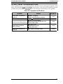
Revision
Issue Date
Revision Page
Rev. A
December 18, 1992
First issue
Added information:
Chapter 2 (Page 2-23)
Chapter 3 (Page 3-5/6)
Chapter 6 (Page 6-1/2)
Rev. B
May 7, 1993
Rev. C
June 11, 1993
Corrected the figure:
Chapter 2 (Page 2-8)
Rev. D
March 10, 1994
Added information:
Appendix (Page A-i, A-5’, A-7’,
A-8’, A-9’, A-1 O’)
-v-
TABLE OF CONTENTS
CHAPTER 1.
CHAPTER 2.
CHAPTER 3.
CHAPTER 4.
CHAPTER 5.
CHAPTER 6.
APPENDIX
GENERAL DESCRIPTION
OPERATING PRINCIPLES
DISASSEMBLY AND ASSEMBLY
ADJUSTMENTS
TROUBLESHOOTING
MAINTENANCE
- vi -
Chapter 1
General Description
Table of Contents
1-1
1.1 FEATURES
1-2
1.2 SPECIFICATIONS
1.2.1 Printing Specification . . . . . . . . . . . . . . . . . . . . . . . . . . . . . . . . . . . . . . . . .1-2
1.2.2 Paper Handling Specification . . . . . . . . . . . . . . . . . . . . . . . . . . . . . . .. ...1-4
1.2.3 Paper Specification . . . . . . . . . . . . . . . . . . . . . . . . . . . . . . . ............1-4
1.2.4 Ink Cartridge . . . . . . . . . . . . . . . . . . . . . . . . . . . . . . . . . . . . . . . . . . ......1-6
1.2.5 Environmental Conditions . . . . . . . . . . . . . . . . . . . . . . . . . . . . . . . .. ....1-7
1.2.6 Electrical Specifications . . . . . . . . . . . . . . . . . . . . . . . . . . . . . . . . . ......1-7
1.2.7 Reliability . . . . . . . . . . . . . . . . . . . . . . . . . . . . . . . . . . . . . . . . . .........1-8
1.2.8 SafetyApproval . . . . . . . . . . . . . . . . . . . . . . . . . . . . . . . ..............1-8
1.2.9 Physical Specification . . . . . . . . . . . . . . . . . . . . . . . . . . . . . . . ..........1-8
1.3 INTERFACE SPECIFICATION
1-9
1-11
1.4 PRINTER OPERATIONS
1.4.1 control panel . . . . . . . . . . . . . . . . . . . . . . . . . . . . ~ . ................1-1 1
1.4.2 Panel Operation at PowerOn . . . . . . . . . . . . . . . . . . . . . . . . . . . . . . . ..1-12
1.4.3 Default Setting . . . . . . . . . . . . . . . . . . . . . . . . . . . . . . . . . . . . . . . . .. ...1-12
1.4.3.1 Default Setting Item . . . . . . . . . . . . . . . . . . . . . . . . . . . . . . .. ...1-12
1.4.4 Initial Ink Charge . . . . . . . . . . . . . . . . . . . . . . . . . . . . . . . . . . . . . . . . .. ..1-13
1.4.5 Error Conditions . . . . . . . . . . . . . . . . . . . . . . . . . . . . . . . . . . . . . . . .....1-13
1-14
1.5 MAIN COMPONENTS
1.5.1 Main Control Board (C106 MAIN BOARD) . . . . . . . . . . . . . . . . . . . . . .. .1-14
1.5.2 Power Supply Unit (C106 PSB/PSE BOARD) . . . . . . . . . . . . . . . . . . . . .1-15
1.5.3 Printer Mechanism (M-481O) . . . . . . . . . . . . . . . . . . . . . . . . . . . . . .....1-15
List of Figures
Figure 1-1. View of the Stylus 800 . . . . . . . . . . . . . . . . . . . . . ...............1-1
Figure l-2. Nozzle Configuration . . . . . . . . . . . . . . . . . . . . . . . . . . . . . . . ......1-2
Figure 1-3. Printable Area - Cut Sheet (Built-in Sheet Feeder) . .............1-5
Figure 1-4. Printable Area - Cut Sheet/ Envelope (Manual Insertion Slot) .. ...1-5
Figure 1-5. Adjust Lever . . . . . . . . . . . . . . . . . . . . . . . . . . . . . . . . . . ..........1-6
Figure 1-6. Temperature / Humidity Range . . . . . . . . . . . . . . . . . . . . . ........1-7
Figure 1-7. Data Transmission Timing . . . . . . . . . . . . . . . . . . . . . .........-..1-9
Figure 1-8. Control Panel . . . . . . . . . . . . . . . . . . . . . . . . . . . . . . . . . . . . . . . . ..1-11
Figure 1-9. C106 MAIN BOARD Component Layout . . . . . . . . . . . . . . . . . . . . .1-14
Figure l-10. C106 PSB/PSE BOARD Component Layout . . . . . . . . . . . . .....1-15
Figure 1-11. Printer Mechanism (M-481O) . . . . . . . . . . . . . . . . . . . . . . . . .....1-15
Rev. A
l-i
List of Tables
Table 1-1. Print Speed and Printable Columns . . . . . . . . . . . . . . . . . . . . . . . . . . 1-2
Table 1-2. Character Tables . . . . . . . . . . . . . . . . . . . . . . . . . . . . . . . . . . . . . . . . 1-3
Table l-3. Adjust Lever Settings . . . . . . . . . . . . . . . . . . . . . . . . . . . . . . . ......1-6
Table l-4. Environmental Conditions . . . . . . . . . . . . . . . . . . . . . . . . . . . . . . ...1-7
Table l-5. Electrical Specifications . . . . . . . . . . . . . . . . . . . . . . . . . . . . . . .. ...1-7
Table l-6. Signal and Connector Pin Assignments . . . . . ..................1-9
Table l-7. Default Setting Item . . . . . . . . . . . . . . . . . . . . . . . . . . . . . . . . .....1-12
Table l-8. Error Codes . . . . . . . . . . . . . . . . . . . . . . . . . . . . . . . . . . . . . . .....1-13
f“”-”’-
I-ii
Rev. A
General Description
STYLUS 800 Service Manual
1.1
FEATURES
The Stylus 800 is a serial inkjet printer that uses a newly developed inkjet technology to accomplish
a superb quality output with high-speed printing. The major features of this printer are:
Ll High print quality from a new inkjet technology.
Cl Fast printing of LQcharacters at 150 cps.
Cl Compact design saves precious work space.
Ci Built-in auto sheet feeder with a capacity fora maximum of 100 cut sheets (either A4 or Letter).
D Equipped with 4 scalable fonts and 15 bit-mapped fonts, standard.
CI 8 character tables for the U.S.
6 character tables for Pacific countries.
16 character tables for European countries.
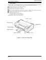
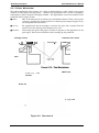
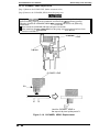
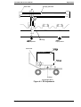
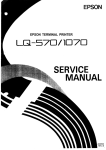
The figure below shows a view of the printer.
printer cover
panel
paper separator
paper feeder cover
Figure 1-1. View of the Stylus 800
Rev. A
1-1
STYLUS 800 Service Manual
General Description
1.2 SPECIFICATIONS
This section provides detailed statistics for this printer.
{
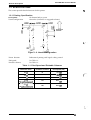
1.2.1 Printing Specification
On-demand ink jet system
48 nozzles (12 nozzles x 4 staggered columns)
Print system:
Nozzle configuration:
0
Paper feed
direction
I.
I
i
I
i
I.
I
i
I
i
II
I,,I
I
I
i’
. ., *
i
# 4 Qi
5
.
Figure 1-2. Nozzle Configuration
Bidirectional printing with logical seeking control
Printer direction:
PMt speed:
See Table 1-1.
See Table 1-1.
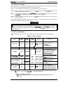
Printable columns:
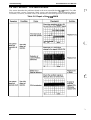
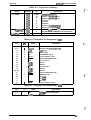
Table 1-1. Print Speed and Printable Columns
Character Pitch
Printable Columns
Print Speed (LQ)
10 cpi
80
150 Cps
12 cpi
96
180
15 cpi
120
225 CPS
17 cpi
(l Ocpi/Condensed)
137
257 Cf)S
20 cpi
(12 cpVCondensed)
160
300 Cps
CPS
,,
f’
-..
1-2
Rev. A
Geneml Descri@ion
STYLUS 800 Service Manual
Character sets:
Legal and 14 international character sets.
Character tables:
See Table 1-2.
Table 1-2. Character Tables
Character Table
US Version
European Version
Pacific Version
o
o
o
o
o
o
0
0
0
0
0
o
o
o
o
o
o
o
o
0
0
0
0
0
o
ITALIC
PC437 (U.S./Standard Europe)
PC850 (Multilingual)
PC860 (Portuguese)
PC863 (Canadian-French)
I
I
PC865 (Nodic)
PC437 Greek
x
PC851 (Greek)
x
PC852 (East Europe)
x
PC853 (Turkish)
x
PC855 (Cyrillic)
x
PC857 (Turkish)
x
PC866 (Russian)
x
I
ABICOMP
BRASCII
Fonts:
[Bit-mppedfonts]
- EPSON Roman
- EPSON %ns serif
- EPSON Courier
- EPSON Prestige
- EPSON Script
IScaldlefmtsl
- EPSON Roman
- EPSON %ns serif
- EPSON Roman T
- EPSON !%IIS %rif H
Print mode:
o
o
I
I
I
I
I
x
x
x
x
x
x
x
I
x
x
x
x
(lOcpi/12cpi/15cpi/Proportional)
(10/12/15/Proportional)
(10/12/15)
(10/12)
(10/12)
8-32
8-32
8-32
8-32
points
points
points
points
(Unit=
(Unit=
(Unit=
(Unit=
2
2
2
2
points)
points)
points)
points)
[For Bit-mppedfontsl
Selection ~-d &xture of the following mode are allowed.
- Print quality (LQ)
- Character pitch (10/12/15 cpi or proportional)
- Condensed (not available with 15 cpi character pitch)
- Double height
- Double width
- Emphasized
- Double strike
- Italic
- Underline
- Double underline
- Overscore
- Shadow / outline
- Strike through
IForscalablefonts]
- Emphasized
- Italic
- Double underline
- Strike through
Control codes:
Rev. A
- Double stike
- Underline
- Overscore
- Shadow / outline
EC,~//~~
1-3
STYLUS 800 Sewice Manual
General Description
1.2.2 Paper Handling Specification
Feeding system:
.f“”
:. .. .
Friction feed from built-in sheet feeder or manual insertion slot.
Notes: The following operation are not al/owed.
1. Reverse feeding within 3 mm (O. 12 inches) from the top edge
of the paper or 16 mm (0.63 inches) from the bottom edge of
the paper.
2. Reverse feeding beyond 7.9 mm (0.3 inches).
Feeding pitch:
1/6, 1/8 inch feed or programmable with a 1/360 inch minimum increment.
Paper path:
Built-in sheet feeder (front entry)
Manual insertion slot (Top-rear entry)
Feeding speed:
87 msec. (at 1/6 inch feed pitch)
1.2.3 Paper Specification
Usable paper:
Cut sheet
~ith Built-in sheet feeder]
Size:
Thickness:
Wighk
Quality:
For European/Pacific version:
A4 (wX L :210mm (8.3”)X 297mm (11.7”))
For U.S. version:
Letter (W x L: 216 mm (8.5”) x 279 mm (11.0”))
0.065-0.14 nun (0.0026 - 0.0055”)
64 - 90g/m2 (18 -24 lb./55 - 78 Kg)
Bond Paper, Photocopier paper
i.:,,-
[With manual insertion]
<Envelope>
Width:
Length:
Thickness:
Wight:
Quality:
182-216 mm (7.2 - 8.5”)
257- 297mm (10.1 - 11.7”)
0.065-0.11 mm (0.0026- 0.0043”)
52- 90g/m2 (14 -24 lb / 45- 78 Kg)
Bond Paper, Photocopier paper
Size:
#6 (W X L : 166 mm (6%”) X 92 mm (35/8”))
#10 (Wx L: 240 mm (914”) x 104 mm (4%”))
0.16-0.52 mm (0.0063 - 0.0197”)
Thickness:
Note:
Weight:
Quality:
The variation in paper thickness within the printable area must be 0.25
mm (0.0098~ or less.
45-90 g/m2 (12 -24 lb.)
Bond paper, Airmail, Photocopier paper
f’
Notes 1. Envelopes are usable only with manual insertion feed.
2. Printing with envelopes guaranteedonly under normal temperature
and humidity condition.
3. Insert envelopes into the manual insertion slot sideways.
,. ,.
1-4
Rev. A
Geneml Description
STYLUS 800 Service Manual
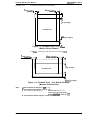
Printable area:
Cut Sheet (with built-in sheet feeder)
B
(Left marain)>
—
4
c
(Right marain]~
.
r
r
!
A
(Top margin)
Printable area
ID
I (Bottom margin)
1
Figure 1-3. Printable Area - Cut S~eet
(Built-in Sheet Feeder)
Cut Sheet / Envelope (with the manual insertion slot)
B
(Left marain) ~.*
c
A
(Top margin)
Printable area
L
&ottom margin)
Figure 1-4. Printable Area - Cut Sheet/ Envelope
(Manual Insertion Slot)
Note:
Rev. A
A: The minimum top margin= 3 mm (0.12”)
B: The minimum left margin= 3 mm (O. 12”)
A4 size= 3.8 mm (O. 15”)
C: The minimum right margin is:
Letter size = 9.7mm (0.38’)
Manual insettion = 3 mm (O. 12’9
D: The minimum bottom margin= 13 mm (0.51’)
1-5
General Description
SNLUS 800 Service Manual
Adjust lever settings:
The adjust lever, attached to the carnage unit, must be set to proper
position for the paper thickness, as shown in Table 1-3.
Table 1-3. Adjust Lever Settings
Lever Position
Paper Type
LEFT
Cut Sheets
RIGHT
Envelopes
Paper Thickness
~;%26--00~iO!$
0 . 1 6 - 0.52 mm
(0.0063- 0.020”)
Plain paper,
(-..
I
I
\
/1
- . . . . . . . . . . . - . . . . . . . . .-
-. I
Figure 1-5. Adjust Lever
1.2.4 Ink Cartridge
Type:
Exclusive cartridge (S020025)
Ink color:
Black
Print capacity:
0.7 million characters (LQ)
Note: This figure is equivalent to a 700page print volume when
printing is performed at 1000 characters perpage on letter or
A4-size paper.
Ink Capacity:
29.0 +0.5/-1.0 CC
Life:
The effective
Temperature conditions:
life from the indicated production date is:
-2 years (total period of time in package and after unpacking)
-6 months (after unpacking)
-30- 40“C (-22 -104 ‘F)
[Storage]
(UDto1monthat40‘C
(140 “ F ) )
[Transport] ~36- 60“C (-22 -140 “F) ““
(Up to 1 month at40“C (104 “F) or 120 hoursat60“C
(140 ‘F))
Note: The ink inside the ink cartridge freezes if it kept below -3’C
(26.6”F). It requires several hours to unfreeze at room temperature (25 ‘C (77°~).
Dimension:
28.5 mm (1.12”)
Width
54.5 mm (2.15”)
Depth
Height 38.5 mm(l.52”)
Genera/ Descriptim
STYLUS 800 Service Manual
1.2.5 Environmental Conditions
Table 1-4. Environmental Conditions
Operating
Storage
10-35 ‘c (50 - 95 ‘I=)(*1)
-20- 60 “C (-4 - 140 ‘F) (*2)
Description
Temperature
20- 80% RH (*1,*3)
Humidity
5-
85~0
RH (*2,*3)
Resistance to shock
1 G, within 1 msec.
2 G, within 2 msec. (*2)
Resistance to vibration
0.15 G, 10-55 Hz
0.50 G, 10-55 Hz (*2)
Note:
● 1 = Operating conditions must be in this range.
*2= When the printer is in the shipping container.
●3 = Without condensation.
Humidity
(%RH)
80Y0
Print assured range
........
/
.......
55~o
20?/0
10” C
27° C
(80” F)
(50” F)
35°C
(95” F)
‘c
(“F)
Figure 1-6. Temperature/ Humidity Range
1.2.6 Electrical Specifications
Table 1-5. Electrical Specifications
120V Version
220- 240V Version
120V AC
220- 240V AC
103.5- 132V
198- 264V
Rated frequency range
50- 60 Hz
50- 60 Hz
Input frequency range
49.5- 60.5 Hz
49.5- 60.5 Hz
0.5 A
0.3 A
Item
Rated voltage
Input voltage range
Rated current
Power consumption
Approx. 13W
Approx. 13W
(self test with 10 cpi LQ characters) (self test with 10 cpi LQ characters)
Insulation resistance
10 MQ, minimum
10 MQ, minimum
(applying 500VDC between AC line (applying 500VDC between AC line
and chassis)
and chassis)
Dielectric strength
Rev. A
10OOVAC rms -1 minute or
1200VAC rms -1 second
(between AC line and chassis)
1500VAC rms -1 minute
(between AC line and chassis)
1-7
STYLUS 800 Service Manual
General Description
1.2.7 Reliability
MTBF:
MCBF:
4000 power on hours (POH) at a duty cycle of 10%
Printhead life:
3 million lines (excluding the printhead)
1 billion dots per nozzle
Total print volume:
75000 pages (with A4 or Letter size paper)
1.2.8 Safety Approval
Safety standards:
US version:
UL1950 with D3
CSA22.2 %220
European version:
Radio frequency interface (RFI):
US version:
European version:
EN 60950 (~V)
IEC 950 (SEMKO, DEMKO, NEMKO, SETI)
FCC part 15, subpart B, Ck.S B
Vfg. 243 (VDE 0878 part 3, part 30)
EN 55022 (CISPR Pub.22) class B
1.2.9 Physical Specification
Size (W x D x H):
Weight
435 X 264X
i~ (mm)
(17.1X 10.4X 6.1 (inch))
Approx. 5.0 Kg (excluding ink cartridge)
,(“”
..
. . .
1-8
Rev. A
GenemlDescription
SNLUS 800 Service Manual
1.3 INTERFACE SPECIFICATION
The Stylus 800 is equipped with an 8 bit parallel interface, standard.
8 bit parallel
STROBE pulse swchronization
By BUSY and ACKNLG signals
TTL-compatible level
36-pin 57-30360 (Amphenol) or equivalent
See Figure 1-7.
Data format:
Synchronization:
Handshaking:
Signal level:
Adaptable connector:
Data transmission timing:
i’b-\
DATA
STROBE— —
L- O. SuS(Min.)
L!&
O. SuS(Min.)
O. SuS(Min.)
Figure 1-7. Data Transmission Timing
Table 1-6 shows the connector pin assignments and signal functions of the 8-bit parallel interface.
Table 1-6. Signal and Connector Pin Assignments
1/0
Description
I
The STROBE pulse is used to read data from the host
computer. The pulse width must be 0.5@ or more. Normally,
it is HIGH, and data is latched with rising edge of this signal.
I
DATA 1-8 are parallel data bits. When one of these signals is
HIGH, the data bit is 1; when LOW, the data bit is O. The most
significant bit (MSB) is DATA 8. The signal state must be
maintained for 0.5 pS on either side of STROBE signal’s active
edge.
ACKNLG
o
ACKNLG is an acknowledge pulse with a width of
approximately 10 vS. This signal goes LOW upon the
completion of data reception, to indicates that the printer is
ready to receive further data.
11
BUSY
o
The BUSY signal informs the host computer of the printe~s
status. When this signal is HIGH, the printer cannot accept
further data.
12
PE
o
This signal indicates whether paper is available in the printer
or not. A HIGH level indicates a no paper condition.
13
SLCT
o
Pulled up to +5V through a 1.0 KQ resistor in the printer.
I
If this signal is set to LOW, the printer automatically performs
one line feed upon receipt of a CR (carriage return) code. The
status of this signal is checked only at power on and
initialization.
Pin No.
1
2-9
10
Signal Name
STROBE
DATA 1-8
14
AFXT
15
NC
Rev. A
Not USed.
1-9
SNLUS 800 Service Manual
General Description
Table 1-6. Signal and Connector Pin Assignments (Continued)
Signal Name
Pin No.
I/o
Description
16
GND
17
CHASSIS-GND
18
NC
Not USed.
19-30
GND
Twisted-pair return signal ground.
31
INIT
32
ERROR
o
This signal goes LOW if the printer:
- has a fatal error.
- runs out of paper.
33
GND
.
Signal ground.
34
NC
.
Not USed.
35
+5V
.
Pulled up to +5 Vthrough 1.0 KW resistor in the printer.
36
-
.
Not used. (* Reserved.)
Note:
1-1o
Signal ground.
-
I
Chassis ground. (Both chassis ground and signal ground are
connected in the ptinter.)
If this signal goes LOW, the printer is initialized. The pulse
width of this signal must be 50 pS or more.
(-
The direction of the signal is as viewed from the printer.
Rev. A
STYLUS 800 Service Manual
General DescriWion
1.4 PRINTER OPERATIONS
This section describes the basic operations of the printer.
1.4.1 Control Panel
The control panel of this printer contains five non-lock type push buttons and nine LED indicators
for easy operation of the various printer functions.
r
\
[
O PAPER OUT
O INK OUT
II o
jALT
5
I
I
ECONOMY
/10
h.
CONDENSED
1’
[
,,
1
1
,
r
ju
I
I
I
r
I
000
J
FONT
D
Ii3
Courier
Romm T PS)
~:a: ($ s)
Saris Sarif
Prestige
script
Q
5
R E SET
LOAD /
EJECT
Figure 1-8. Control Panel
[Buttons]
PAUSE
Switches printer status between printing and no printing, if any
print
dataexists
in
the
input
buffer: - - - -
ECONOMY/CONDENSED
Selects ECONOMY printing mode or CONDENSED printing mode
alternately. Also works as a reverse micro feed button, if the ALT
button has been pressed.
Selects one of the available fonts. Also works as a forward micro
feed button, if the ALT button has been pressed.
FONT
LOAD/EJECT
When you press this button, the printer either loads new paper into
the printer or ejects paper currently in the printer paper path. Also
works as a RESET button, if the ALT button has been pressed.
ALT
This button alternates the function of certain buttons. When you
hold down this button in PAUSE mode for 5 seconds, the printer
moves the carriage to the ink cartridge installation/replacement
position.
[Indicators]
PAUSE
Lights when the printer is in PAUSE mode.
DATA
PAPER OUT
Lights when there is print data in the input buffer.
Lights when the printer is out of paper. Blinks if a paper jam has
occurred.
Lights when the printer detects ink end in the ink cartridge. Blinks
when the ink level becomes low.
INK OUT
ECONOMY/CONDENSED
This LED shows the currently selected mode.
FONT
lndicatw the currently selected font.
Rev. A
1-11
STYLUS 800 Service Manual
General Description
1.4.2 Panel Operation at Power On
The following functions can be activated at power on by holding down the specified button on the
control panel.
Start the self-test printing mode by turning the printer on while
holding down the FONT button.
Start the built-in hexadecimal data dump print mode by returning
the printer on while holding down the FONT and LOAD/EJECT
buttons. Once this mode is selected, the printer prints all received
print data in hexadecimal form.
Self-test mode:
Hex dump mode:
Start printing of a demonstration page by returning on the printer
while holding down the ALT button.
Demonstration mode:
Other functions that can be activated with the control panel at power on, such as the default setting
mode and the initial ink charge mode, are described in the sections that follow.
1.4.3 Default Setting
The printer can memorize certain number of printer setting parameters that defines its functions at
the initialization. You can change these parameters with the default setting mode for your specific
preference of the printer setting.
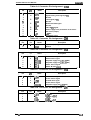
1.4.3.1 Default Setting Item
The settings listed in the table below can be made with the default setting mode. The default-setting
mode can be activated by hold down the ECONOMY/CONDENSED button while turning on the
printer. (Refer to the use~’s guide for the detail operation of the default-setting mode.)
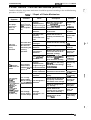
Table 1-7. Default Setting Item
Menu
Contents
Character Table
Description
Facto~
Setting
Select the character table
Auto Print Direction
ON: Print direction is automatically selected as to maintains
optimal print quality (alignment).
OFF: Depends on the command ‘ESC U’.
ON
Network l/F Mode
ON: For network environment, such as LocalTalk.
(Time-out printing is disabled.)
ON: For normal environment. (llme-out printing is enabled.)
OFF
Mixed Text/Graphics
Mode
ON: To ensure proper printing of the image containing
graphics and scalable font, with certain applications,
such as MS Word, WordPerfect V.5. I or earlier. ● 1
OFF: For normal use.
OFF
Auto Line Feed
ON: Line feed operation is automatically performed by CR
code input.
OFF:NO line feed operation with single CR code.
OFF
Note:
*1= If set to ON, the capacity of input buffer is limited to 8 Kbyte,
. . ..
f
General Description
SWLUS 800 Service Manual
1.4.4 Initial ink Charge
When the printer is to be set up for primary use, whole ink supply path of the printer must be filled
with a new ink, by performing the initial ink charge operation.
[Step 1] Turn the printer on and press the PAUSE button to pause the printer.
[Step 2] Open the printer cover and hold down the ALT button until the printhead moves to the
ink cartridge replace position.
[Step 3]
Install the ink cartridge on the printhead, and press the ALT button again to move the
printhead to capping position. Then, turn off the printer.
[Step 4] Turn the printer on while holds down the ALT and the PAUSE buttons to start the initial
charge operation.
The PAUSE LED blinks while the initial ink charge operation is in progress, and when it completes,
the printer automatically becomes ready state.
W The ink cartridge must be installed just after unpacking the package.
H The initial ink charge operation should not be pe@ormed more than trm”ce on the same
printer. It, otherwise, consumes too much ink in the ink carh”dge and shorten the waste
ink tank life.
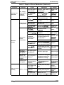
1.4.5 Error Conditions
he printer detects various errors and indicates them with the LED indicators and the buzzer.
Table 1-8. Error Codes
PAPER
LED
Error
INK END
LED
PAUSE
LED
Buzzer
Recovery
V4 x 3 times
Load the paper and press the
buttons as follows:
1. PAUSE
2. LOAD/EJECT
Paper out
ON
OFF
OFF
Paper jam
BLINKS
OFF
OFF [ V4 x 3 t i m e s
I
Ink low ● 1
Inkend I
I
OFF
BLINKS
OFF
ON
ON
OFF
Waste ink tank
over-flow
Notes: V :
+ :
OFF
ON
No beeps
Same as above.
Press PAUSE button and
replace the ink cartridge with
a new one. Then, press
PAUSE button again to
resume printing. ● 2
Replace the ink cartridge and
press
PAUSE button.
=t==
=-l--==
BLINKS
4 :
0.1 second beep
0 . 1 s e c o n d intetval + :
V+ x 3 times
Install the ink cartridge and
mess PAUSE button.
Turn off the printer, and turn
it on again.
Service maintenance
required. (Replace the waste
ink absorbing material and
reset the protect counters.)
0.5 second beep
0.2 second interval
‘1: This is not treated as an error.
*2: It is not necessary to replace the ink cartridge until the printer detects the ‘Ink
End’ error.
Rev. A
1-13
STYLUS 800 Service Manual
General Description
1.5 MAIN COMPONENTS
,. . ,
(.
The main components of this printer are:
.!
O Printer mechanism (M-481O)
Q Main control board (C106 MAIN BOARD)
~ Power supply unit (C106PSB/PSEBOARD)
Cl Control panel
Cl Housing
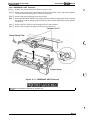
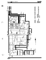
1.5.1 Main Control Board (C106 MAIN BOARD)
The C106 MAIN BOARD is the main conboller of the Stylus 800. It takes charge of interfacing with
the host computer and processing of received print data, as well as control of the whole printer
mechanism. This board consists of the following components.
CPU (IC1):
8-bit CPU (TMP96C141F-20)
19.6608 MHz operating clock
Gate-array (IC3):
Includes the following functions:
- MMU (Memory Management Unit)
- IFU (Interface Control Unit)
- BMU (Bit Manipulation Unit)
- PCU (1/0 Port Control Unit)
- Head control unit (2 channel: HCU1, HCU2)
Program ROM (IC4):
1 Mbit EPROM
CG ROM (IC7/8):
4 Mbit Mask ROM (IC8 / for US, Pacific version)
8 Mbit Mask ROM (IC7 / for European version)
RAM (IC5):
1 Mbit PSRAM
EEPROM (IC1O):
1 Kbit (64 x 16 Bit) EEPROM
3 lines serial bus
CR Motor driver (IC13):
Hybrid IC SMA7024MEL
Constant current unipolar drive
PF Motor driver (QM1):
Hybrid IC SMA6501
Constant voltage unipolar drive
.c,
n
I
Un
u u
Figure 1-9. C106 MAIN BOARD Component Layout
1-14
Rev. A
General Description
STYLUS 800 Service Manual
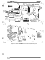
1.5.2 Power Supply Unit (C106 PSBIPSE BOARD)
The power supply unit converts input AC voltage and generates different DC voltages required by
the printer mechanism and other electrical circuities. The C106 PSB BOARD is for 120VAC input,
and the C106 PSE BOARD is for 220 to 240VAC input.
—
/-
o
Figure 1-10. C106 PSBIPSE BOARD Component Layout
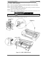
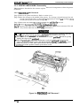
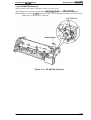
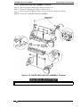
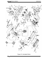
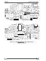
1.5.3 Printer Mechanism (M-481O)
This printer mechanism M-481O is specifically designed for the Stylus 800, and it consists of the
carriage assembly, which includes the printhead and the ink supply system, the carriage motor, the
paper feed motor, the paper feeding mechanism, and the pump mechanism.
Figure 1-11. Printer Mechanism (M-481O)
.—. —.—.
Rev. A
1-15
,. . . . .
f.:,’
.
Chapter 2
Operating Principles
Table of Contents
2.1 OVERVIEW
2-1
2-1
2.2 OPERATING PRINCIPLES OF THE PRINTER MECHANISM
2.2.1 Printer Mechanism . . . . . . . . . . . . . . . . . . . . . . . . . . . . . . . . . . . . . . . .. .2-2
2.2.2 Carriage Drive Mechanism . . . . . . . . . . . . . . . . . . . . . . ...............2-4
2.2.2.1 Platen Gap Adjust Lever . . . . . . . . . . . . . . . . . . . . . . . . . . . . . . . .2-4
2.2.3 Paper Feed Mechanism . . . . . . . . . . . . . . . . . . . . . . . . . . . . . . . . .......2-5
2.2.4 Ink System . . . . . . . . . . . . . . . . . . . . . . . . . . . . . . . ..................2-6
2.2.5 Pump Mechanism . . . . . . . . . . . . . . . . . . . . . . . . . . . . . . . . . . ..........2-7
2.2.6 Cap Mechanism . . . . . . . . . . . . . . . . . . . . . . . . . . . . . . . . . . . . . ........2-9
2-1o
2.3 OPERATING PRINCIPLES OF THE ELECTRICAL CIRCUITRIES
2.3.1 Operating Principles of the Power Supply Circuit . . . . . . . - . . . . . .....2-10
2.3.2 Operating Principles of the Main Control Circuit . . . . . . . . . . . . . . .....2-12
2.3.2.1 Reset Circuits . . . . . . . . . . . . . . . . . . . . . . . . . . . . . . . . . . .....2-13
2.3.2.2 Sensor Circuits . . . . . . . . . . . . . . . . . . . . . . . . . . . . . . . . . .....2-13
2.3.2.3 Ink End Detection . . . . . . . . . . . . . . . . . . . . . . . . . . . . . . . .....2-14
2.3.2.4 Carriage Motor Drive Circuit . . . . . . . . . . . . . . . . . . . . . . . . . . . .2-15
2.3.2.5 Paper Feed Motor Drive Circuit . . . . . . . . . . . . . . . . . . . . . .....2-16
2.3.2.6 Printhead Drive Circuit . . . . . . . . . . . . . . . . . . . . . . . . . . . . . . ...2-17
2-18
2.4 INK SYSTEM MANAGEMENT
2.4.1 Ink Operations . . . . . . . . . . . . . . . . . . . . . . . . . . . . . . . . . . . . . . . . .....2-19
2.4.1.1 PowerOn Operation . . . . . . . . . . . . . . . . . . . . . . . . . . . . . . . ...2-19
2.4.1.2 Cleaning Operation . . . . . . . . . . . . . . . . . . . . . . . . . . . . . . .....2-19
2.4.1.3 Standby Operation . . . . . . . . . . . . . . . . . . . . . . . . . . . . . . . .....2-20
2.4.1.4 Initial Charge Operation . . . . . . . . . . . . . . . . . . . . . . . . . . . .....2-20
2.4.1.5 Refresh Operation . . . . . . . . . . . . . . . . . . . . . . . . . . . . . . . .....2-20
2.4.1.6 Cleaner Blade Operation . . . . . . . . . . . . . . . . . . . . . . . . . . . . . . .2-21
2.4.1.7 l/C Replacefnent Operation . . . . . . . . . . . . . . . . . . . . . . . . .....2-21
2.4.1.8 Disengage On Operation . . . . . . . . . . . . . . . . . . . . . . . . . . .. ...2-22
2.4.1.9 Micro Absorbing Operation . . . . . . . . . . . . . . . . . . . . . . . . .. ...2-22
2.4.2 Counter and Timer . . . . . . . . . . . . . . . . . . . . . . . . . . . . . . . . . . . . . .....2-22
2.4.2.1 Refresh-l Timer . . . . . . . . . . . . . . . . . . . . . . . . . . . . . . . . . .....2-22
2.4.2.2 Flushing Counter . . . . . . . . . . . . . . . . . . . . . . . . . . . . . . . . .....2-22
2.4.2.3 CLCounter K . . . . . . . . . . . . . . . . . . . . . . . . . . . . . . . . . . . .....2-22
2.4.2.4 Protect Counter . . . . . . . . . . . . . . . . . . . . . . . . . . . . . . . . . .....2-23
Rev.A
2-i
List of Figures
~...,,
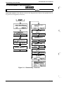
Figure 2-1. Functional Block Diagram of the Printer Mechanism . ...........2-1
Figure 2-2. Structure of Printhead . . . . . . . . . . . . . . . . . . . . . ...............2-2
Figure 2-3. Principles ofthe Printing Operation . . . . . . . . . . . . . . . . . . . . . ....2-3
Figure 2-4. Carriage Drive Mechanism . . . . . . . . . . . . . . . . . . . . . . . . . . . . . . . .2-4
Figure 2-5. Platen Gap Adjust Lever . . . . . . . . . . . .......................2-4
Figure 2-6. Paper Feed Mechanism . . . . . . . . . . . . . . . . . . . . . .............2-5
Figure 2-7. Diagram ofthelnkSystem . . . . . . . . . . . . . . . . . . . . . . . . . . . . . . ..2-6
Figure 2-8. Pump Mechanism Block . . . . . . . . . . . . . . . . . . . . . .............2-7
Figure 2-9. Pump Operation . . . . . . . . . . . . . . . . . . . . . . . . . . . . . . . .........2-8
Figure 2-10 Cap Mechanism . . . . . . . . . . . . . . . . . . . . . ..................2-9
Block Diagram of the Electrical Circuities . . . . . . . . . . . . . . .....2-10
Figure 2-11 ~D•Œ
Power
Supply Circuit Block Diagram . . . . . . . . . . . . . . . . . .....2-11
Figure 2-12
Figure 2-13 Main Control Circuit Block Diagram . . . . . . . . . . . . . . . . . . .....2-12
Figure 2-14 ResetCircuit Block Diagram . . . . . . . . . . . . . . . . . . . . . . . . .....2-13
Figure 2-15 Sensor Circuit Block Diagram . . . . . . . . . . . . . . . . . . . . . . . .....2-13
Figure 2-16. Ink End Detection Sequence . . . . . . . . . . . . . . . . . . . . . . . .....2-14
Figure 2-17. Carriage Motor Drive Circuit Block Diagram . . . . . . . . . . . . .....2-15
Figure 2-18. Paper Feed MotorDriveCircuit Block Diagram . . . . . . . . . .....2-16
Figure 2-19. Printhead Drive Circuit Block Diagram . . . . . . . . . . . . . . . . .....2-17
Figure 2-20. Relation oflnkSystem Operation and Carriage Position . . .....2-18
~:
(,: ,
List of Tables
Table
Table
Table
Table
Table
Table
Table
2-1.
2-2.
2-3.
2-4.
2-5.
2-6.
2-7.
Carriage Drive Motor Specification . .........................2-4
P l a t e n Gap Adjust Lever Position . ..........................2-4
Paper Feed Drive Motor Specification . .......................2-5
Pump Mechanism Operation . . . . . . . . . . . . . . . . . . . . . . . . . . . . . . .2-8
DC Voltage Distribution . . . . . . . . . . . . . . . . . . . . . . . . . . . . . . .. ..2-10
Carriage Motor Drive Modes . . . . . . . . . . . . . . . . . . . . . . . . . ....-2-15
Paper Feed Motor Drive Modes . . . . . . . . . . . . . . . . . . . . . . . .....2-16
., .,
2-ii
Rev.A
Operating Principles
STYLUS 800 Service Manual
2.1 OVERVIEW
This section describes the operating principles of the printer mechanism and the electrical circuits of
the Stylus 800.
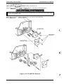
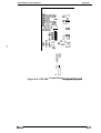
2.2 OPERATING PRINCIPLES OF THE PRINTER MECHANISM
The Stylus 800 printer mechanism is composed of the printhead unit, paper feed mechanism,
carriage drive mechanism, pump mechanism, and various sensors. The figure below shows a
functional block diagram of the printer mechanism.
I
I
w.%“’einkdrain
m
n
D
CR
Motor
MecK mism
]
Garr i age Un i t
Printhead/
Filter/
Driver circuit
1
m
m
~. . . . . . . . . .
n
*
ASF
(Auto Sheet
Feeder)
Figure 2-1. Functional Block Diagram of the
Printer Mechanism
Rev. A
2-1
STYLUS 800 Service Manual
Operating Principles
2.2.1 Printer Mechanism
The printer mechanism of this printer uses a drop-on-demand ink jet system similar to the system
used on all other Epson ink jet printers. However, the printhead in this system is completely
redesigned to make it compact and highly reliable. The figure below shows the structure of the
printhead and ink supply system.
■ MLP
MLP is the abbreviation for Multi-Layer Piezoelectric element. When a drive pulse
(voltage) is applied, this element pushes the vibration plate, compressing the cavity
for ink injection from the nozzle.
■ Cavity
Ink supplied from the ink cartridge is stored in this space and is injected from the
nozzles when the vibration plate compresses this area.
■ Nozzles
These inject ink against the paper’s surface in response to the application of the
print signal. There are 48 individual nozzles making up this printhead.
Cartridge needle
f-”
Printhead driver board
\
I
Filter
Cavity
(Nozzle)
Nozzle plat
(Multi-Layer Piezo)
set
A7’Nozz’e
,,, . . .
f ‘
nk supply tank
Viblation p
\
MLP
(Multi-byer Piezo)
Figure 2-2. Structure of Printhead
-. . .
2-2
Rev. A
Operating Principles
STYLUS 800 Service Manual
Principles of the Printing Operation
The operation of the printhead to inject ink from each nozzle is:
(1) Normal state
No electrical charge is applied to the MLP (Multi-Layer Piezoelectric) element attached to the back
of the cavity, and pressure inside the cavity is kept at constant level.
Nozzl
(2) Injecting state
The head data signal is applied to the specific nozzle control line to select the active nozzle for
printing, and the MLP element is gradually charged by the drive voltage. By charging the MLP
element, the vibration plate is bent to compress the cavity. Then, ink is injected from the nozzle.
@
Figure 2-3. Principles of the Printing Operation
When the ink charge or printhead cleaning operation is performed, the ink in the cavity is
vacuumed out with the pump mechanism. During printing, on the other hand, the ink is
simultaneously supplied from the ink cartridge and injected from the nozzle, according to the
change of volume in the cavity.
A thermistor is attached to the printhead drive board to monitor the temperature, because the
viscosity of the ink varies, depending on the temperature. The detected temperature level is fed
back to the printhead drive voltage control circuit to regulate the drive voltage to a proper level.
Rev. A
2-3
STYLUS 800 Service Manual
Operating Principles
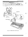
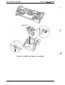
2.2.2 Carriage Drive Mechanism
The timing belt attached to the base of the carriage unit is driven by the carriage motor, causing the
carriage unit to move along the carriage guide shaft left to right, or vice versa. The carriage drive
motor on this printer is a 4-phase, 200-pole, hybrid-type stepping motor mechanism, allowing the
printer to stop the carriage or change the carriage movement at any position. The position of the
carriage is recognized by the home position sensor and position information is fed back to the
carriage drive control circuit to determine the motor phase switching mode.
‘-i.,
(’
.
Table 2-1. Carriage Drive Motor Specifications
I
Item
I
Description
Motor Type
4-phase / 200-pole hybrid-type stepping motor
Drive Voltage
35 V f 10Yo (31.5 -38.5 V)
Coil Resistance
10.0 Qt 7%/ pole (at 25° C, 77° F)
Drive Frequency
960 -5400 pps
Excitation Mode
1-2 phase excitation
Figure 2-4. Carriage Drive Mechanism
2.2.2.1 Platen Gap Adjust Lever
Set the platen gap adjust lever, attached to the carriage unit, to an appropriate position for the
paper thickness used for printing.
Table 2-2. Platen Gap Adjust Lever Position
Platen Gap
Lever Position
Paper Type
Cut sheet
Horizontal (A)
Envelope
Vertical (B)
—
+0.7 mm
Envelope
Plain paper, Bond paper
\
\
(gn~
r
/
:,.,,. .. .:. ...:.:
, . . . ./
P
::,.
/ -.
>
)
..
::::
:,‘L::
. . . . . . . . . .;:
...:
<.~j
.’
-. . . . . . . . . . . . . . . --
Figure 2-5. Platen Gap Adjust Lever
. .,
Operating Principles
STYLUS 800 Service Manual
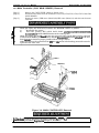
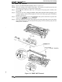
2.2.3 Paper Feed Mechanism
This printer’s paper feed mechanism can feed paper either from the built-in ASF (auto sheet feeder)
or the manual feed slot. The paper feed drive motor is a 4-phase, 4t3-pole, PM-type stepping motor
that directly drives the paper feed mechanism (paper advancing operation, paper pick-up
operation). This motor also drives the pump mechanism, but only when the printer is in the
cleaning state.
Table 2-3. Paper Feed Drive Motor Specification
Description
Item
)
Motor Type
4-phase / 48-pole PM-type stepping motor
Drive Voltage
35 V + 10% (31.5 - 38.5 V)
Coil Resistance
54 ~ 3 Q/ pole (at 25° C, 77° F)
Drive Frequency
650-800 ppS
Excitation Mode
2-2 phase excitation
Figure 2-6. Paper Feed Mechanism
Rev. A
2-5
STYLUS 800 Sewice Manua)
Operating Principles
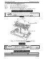
2.2.4 Ink System
!-. .:,,
(..
This printer’s ink system is composed of the following mechanisms:
■ Ink cartridge
■ Pump mechanism
E Cap mechanism
H Printhead cleaning mechanism
■ Waste ink drain tank
The figure below shows a diagram of the ink system.
Ink Cartridge
Head Driver
Filter
Boar
{-
!
Figure 2-7. Diagram of the Ink System
1
..
.
2-6
Rev. A
)
Operating Principles
STYLUS 800 Service Manual
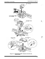
2.2.5 Pump Mechanism
The paper feed motor drives the pump mechanism when the transmission gear is moved to the
position where the paper feed motor engages the pump mechanism gear trains, when the carriage
unit is at the ink system home position. The figure below shows a block of the pump mechanism.
Pump system operation depends on the rotational direction of the paper feed drive motor, as
shown in table below.
<Drive: Pump mechanism>
<Switch lever: Set>
~-——
L
rl
L.+ \
- - - - --1
- - - - -
;
L--–
k--; ;
LJ
J
cDrive: Paper feed mechanism>
<Switch lever: Reset>
5$7
I
I
I
1P
II
IJ
s)’
Figure 2-8. Pump Mechanism Block
Rev. A
2-7
STYLUS 800 Service Manual
Operating Principles
Table 2-4. Pump Mechanism Operation
f“’.,
Operation
PF Motor Rotational Direction
CW (forward rotation)
Pumping
Pseudo-pumping (False absorbing)
Gear backrush com~ensation
CCW (backward rotation)
Pump pulley reset
Gear backrush compensation
1
(,
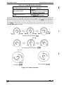
The pump draws ink from the printhead nozzles and drains it into the waste ink drain tank. The
printer performs this operation to eliminate dust or bubbles within the nozzles. Figure 2-9
illustrates the pump operation. When the paper feed drive motor rotates CW (forward), the pulley
pumps in the wheel pump unit rotate in the direction of the arrow while squeezing the ink tube to
push the ink inside the tube out to the waste ink drain tank. On the other hand, when the motor
rotates CCW, the pulley pumps move inward along the grooves of the wheel pump so that pressure
applied to the ink tube is released.
“L’
Pumping (Pump motor:
Cw)
Uflfouch
@+@
No pumping (Pump motor: CCW)
Wheel Pump
/
~..,...
Pulley Pump
Pumping (CW)
No pumping (CCW)
Figure 2-9. Pump Operation
Operating Principles
STYLUS 800 Service Manual
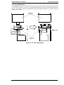
2.2.6 Cap Mechanism
The cap mechanism prevents the printhead nozzles from drying or bubbles from forming inside the
nozzle while the printer is not in use. The printhead capping operation is performed automatically
so that a cap closely contacts the printhead surface when the carriage unit is moved to the ink
system home position.
1
Carriage
(Printhead)
I
. ‘d
.
I
[
w
:--,
::
::
::
::
::
::
.I
I I*
.. .. .. ..
F
\
Slider Valve
,,
::
c,
::
:. ..:
Figure 2-10. Cap Mechanism
Rev. A
2-9
STYLUS 800 Service Manual
Operating Principles
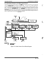
2.3 OPERATING PRINCIPLES OF THE ELECTRICAL CIRCUITRIES
,,, 1,
The Stylus 800 contains the following circuit board units:
f
...
■ C106 MAIN BOARD (Main control circuit board)
■ C106 PSB/PSE BOARD (Power supply circuit board)
In addition to the circuit boards above, part of the printhead drive circuit is built on a separate
circuit board installed in the carriage unit, and the printhead is attached directly to this board. The
figure below shows a block diagram of the electrical circuitries.
M-481 O
Printer mechanism
AC Input
/Carriage
,------- . . . . . . . . . . . . . . . . . . . . . . . . . . . . . . . . . . . . . . . . . . . . . . . . . . . .
/
,\
. . . . . . . . . . . . . . . . . . . . . . . . 1.....
Head drive
* voltage
(+35VDC)
Head driver
Board
C106
PSB/PSE
I Printhead I
..................................
+35VDC
+5VDC
(’,”
C106
MAIN
EEJ+
L
. . . . . . . . . . -. . . . . . . . . . . . . . . . . - . . . . . . . . . .- - -- - - . . . . . . . - - - -- .-’
C106 PNL
L
I
Figure 2-11. Block Diagram of the Electrical Circuities
,. .,%
{.
2.3.1 Operating Principles of the Power Supply Circuit
The power supply circuitry for this printer is provided either by the C106 PSB BOARD (120 VAC)
or the C106 PSE BOARD (220-240 VAC). Both boards are identical in design and functionality,
except for components in the primary circuit that accommodate the specified input voltage. l%e
input voltage and the application of output voltages are summarized in table below.
Table 2-5. DC Voltage Distribution
I
Application
Voltage
~
+35 VDC
~Motor drive (carriage and paper feed)
~Printhead (through the drive voltage generation circuit)
/ C106 MAIN BOARD
+5 VDC I Sensors (home position and paperend)
1 Control panel
~(PF motor holding voltage)
.,
2-1o
Rev. A
Operating Principles
STYLUS 800 Service Manual
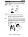
The figure below shows a block diagram of the power supply circuit (C106 PSB/PSE). This power
supply circuit employs the RCC (ringing choke converter) switching control system. The input AC
voltage supplied from the external AC source is first input to the filter circuit for higher harmonics
absorption. The AC voltage is then input to the rectification and smoothing circuit, converting it
into DC voltage. This DC voltage is input to the switching circuit for switching operation. Along
with the switching operation on the primary side, +35 VDC is generated after passing through the
smoothing circuit. The +35 VDC level is fed back to the primary switching circuit through the +35
V line voltage detection circuit and, thus, the +35 VDC output level is stabilized. This +35 VDC is
also input to the +5 VDC generation circuit to generate a stable +5 VDC.
Primary-side
C7
QI
~~
Smoothing
Circuit
w-J----
4
Secondary-side
*“V”’
T1
,.—.
.—,
C51/C52
I
Main
Switching I--Id
L
9
ZD52
1-
k
C21C
CIIR1
Filter
Circuit
Pcl !–
-44+
+35VDC
u
+5V
Full-wave
Rectifier
Circuit
L1/C6
lC51/Q51/L51
D5!YR53/C55
—
+
ZD511R70/R711R72/Q52
+35V
—
Constant
Over-current
Protection
. .
Voltage
. . Control Crcult
ZD53
-
AC Input
Figure 2-12. Power Supply Circuit Block Diagram
This circuit contains the protection circuits described below.
1)
2)
3)
4)
+5 VDC line over voltage protection circuit
The output voltage level of +5 V line is monitored with a Zener diode (ZD53) and if the voltage
level exceeds predefined level (+7 V), the status is fed back to the primary switching circuit
through a photocoupler (PC1) to stop the +35 V generation.
+5 VDC line over current protection circuit
The output current is monitored with a detection resistor (R53) and fed back to the +5 VDC
generation switching control IC (IC51). If the current level exceeds the limit, the control IC
shortens the ON time of the switching transistor (Q51) to decrease the output voltage level
(constant current operation).
+35 VDC line over voltage protection circuit
The output level is monitored with a Zener diode (ZD36). If the voltage level exceeds the limit
level (+36 V), it activates a photocoupler (PC1), and this stops the primary switching circuit
operation.
+35 VDC line constant voltage output control circuit
The output level of +35 VDC line is monitored by a detection circuit that consists of a Zener
diode (ZD51), a transistor (Q52), and resistors (R70, R71, R72). This circuit feeds back the
output voltage level status through a photocoupler to the primary switching circuit to control
the ON/OFF time of the switching transistor for constant output voltage control.
Rev. A
2-11
STYLUS 800 Service Manual
Operating Principles
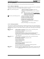
2.3.2 Operating Principles of the Main Control Circuit
The main control circuit of this printer is the C106 MAIN BOARD. This circuit is controlled by the
8-bit CPU TMP96C141F (ICI), running at 19.6608 MHz. This CPU has a unique architecture
capable of handling data on the data bus at either an 8-bit bus width or a 16-bit bus width. Due to
this, a 16-bit data bus width-type ROM is used on this board, increasing the internal processing
speed. Gate array E05A85EB (IC3) manages pnnthead drive control, external I/F control
(Centronics parallel I/F), and the control panel. The CPU directly controls both the carriage drive
motor and the paper feed motor. This board is also equipped with EEPROM 93C46 (IC1O) to store
certain parameters, such as the printer mechanism control parameter, default setting parameters, as
well as a special counter value used for pririthead protection.
,. . :;c. . . ;
\ Common
~’
* Drive Circuit ~
I
Pwcl
!
~’--”;.
.............................
I
IC3
E05A85EB
t
I
.
r–––––
Head driver
(Printhead)
Sl(Data)iLAT
; (PWC/PWD) ~
PWD
.
I ——————
IC8 *1
IC7 *2
PROM(1 M)
Mask ROM
Mask ROM
PS-RAM
(Prog ram)
(CG14M)
(CGI16M)
(1 M)
IC4
(-
IC5
CRO-3
I
I
I
ADO-15
I
Icl (CPU)
TMP96C141
BzEl
P60x
P61x
1
IC13
?
CR Motor
V
Control
—
QMI
SMA6501
PF Motor
Panel
(C106 Pt’d;)
Note:
.
●2:.
E41/Pacific only
Europe only
Figure 2-13. Main Control Circuit Block Diagram
,. .,.
( ,’
Operating Principles
STYLUS 800 Service Manual
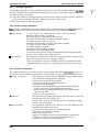
2.3.2.1 Reset Circuits
The C106 MAIN BOARD contains two reset circuits: the +5 V monitor reset circuit and the +35 V
monitor reset circuit. The +5 V monitor reset circuit monitors the voltage level of the +5 V line,
using reset IC PST592 (IC12), and outputs a reset signal to both the CPU (ICI, TMP96C141) and the
E05A85EB gate array (IC3), when the voltage level drops below +4.2 V. The +35 V monitor reset
circuit, on the other hand, monitors the voltage level of the +35V line, using reset IC 51955BFP
(IC1l), and outputs a reset signal to the CPU. The reset signal is generated when the voltage level
drops below +28 V, and this causes a non-maskable interrupt (NMI).
+3SVDC
+5VDC
&&
7
I_-EL.J
237
RESET
E05A85EB
(IC3)
Figure 2-14. Reset Circuit Block Diagram
2.3.2.2 Sensor Circuits
The following sensor circuits enable the main board to monitor printer mechanism status:
1) HP sensor
A photocoupler-type HP (home position) sensor is attached to the back of the
carriage unit to detect the carriage home position as a print reference position. A
HIGH level from the signal indicates that the carriage is in home position.
2) PE sensor
A mechanical switch PE (paper end) sensor is built into the printer mechanism to
determine whether there is paper in the printer or not.
Two electrical contacts are attached to the ink cartridge holder in the carriage unit,
and when the ink cartridge is installed, the metal pins built into the ink cartridge
touch these contacts. The IE (ink end) sensor circuit applies a HIGH level signal
when performin g the ink end status detection operation. The ink level is
determined by the resistance between the two contacts by measuring the input
signal level with analog port ANO (pin 73) of CPU.
3) IE sensor
4) Thermistor
A thermistor is attached to the printhead unit to monitor its temperature. The CPU
changes the printhead drive signal’s pulse width (charge pulse width) based on the
temperature level.
PE
+5V
+5V
(CN4)
+5V
10 I
JJ r k)
P
x
9
slve
E05A85E9
(IC3)
+5V
80
w
m
IC9
INK ~
Cl=u
(lCl)
+5V
Ink
cartlt@l?
“1
i ..~:~ i
,.
.
,,,
L.—. J
‘+”
‘
I
Figure 2-15. Sensor Circuit Block Diagram
Rev. A
2-13
STYLUS 800 Service Manual
Operating Principles
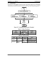
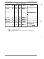
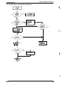
2.3.2.3 Ink End Detection
The IE (Ink End) sensor attached to the carriage detects, not only the ink end, but also when ink is
low and whether an ink cartridge is installed. The detected status is classified to five modes
according to the output voltage level of the IE sensor.
❑ Mode A:
❑ Mode B:
9 Mode C:
■ Mode D:
■ Mode E:
No I/C (Abnormal conduction)
Ink is low
Ink end (During pump operation)
Ink end (During printing)
No I/C (not installed)
(not printable)
(printable)
(not printable)
(not printable)
(not printable)
r=l
rIst check
A < Vout c B ?
(
,.,
u’
L*-,
a
r--+
.,>
f,
b&K-.l
Figure 2-16. Ink End Detection Sequence
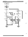
When the ink end detection operation has determined ink status, the printer indicates the status on
the control panel, as described below:
2) During pump operation:
If Mode D (ink end) or Mode A or E (no I/C) is detected, the
pnnthead is capped and the control panel indicates an “INK END”
error.
If Mode C is detected, the printer indicates an “INK END” error after
the detection operation sequence completes and interrupts pump
operation.
If Mode A or E is detected, the printer indicates an “INK END” error
after interrupting the pump operation.
3) In stand-by state:
If Mode D or Mode A or E is detected, the printer indicates an “INK
END” error on the control panel.
1) During printing:
2-14
Rev. A
4,,,,,
Operating Principles
STYLUS 800 Service Manual
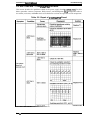
2.3.2.4 Carriage Motor Drive Circuit
I
Carriage motor drive IC SLA7024 (IC13) drives the carriage motor for the printer mechanism by a
constant current, unipolar drive system. Gate array E05A85EB (IC3) selects the motor phase drive
current level using the output signals from ports CRO to CR3 (pins 75 to 78). The phase switching
operation is directly controlled by the phase control signals output from ports P600 to P603 (pins 1
to 4) of the CPU. The table below shows the carnage m-otor drive modes. -
Table 2-6. Carriage Motor Drive Modes
CR speed
(CPS)
Drive
Frequency
(PPS)
Phase
Excitation
Acceleration
Current
(A/Phase)
Normal/Deceleration
Current
(A/Phase)
225
5400
1-2 phase
0.80
0.45/0.80
150
3600
1-2 phase
0.60
0.30/0.60
83
2000
1-2 phase
0.80
0.80
40
960
1-2 phase
0.45
0.30/0.45
HOLD
—
2 phase
Approx. 0.15
SLA7024MEL
(IC13)
CPU
(ICI)
P600 ‘
P601 2
P603
P602
‘
+35V
7
INB
IN-A
16 IN.B
3
5
4
8
A
1
-A
+5V
18
R59
E05A85EB CRO 78
(IC3)
CR1 77
CR2 76
75
CR3 -
CR
Motor
(CN6)
6 INA
WRM26
RM25
RFA
RFB
B
11
-B
—
; CRCOM
* CRA
s CR-A
b CRB
CR-B
R33
R34
R35
R36
Figure 2-17. Carriage Motor Drive Circuit Block Diagram
STYLUS 800 Service Manual
Operating Principles
2.3.2.5 Paper Feed Motor Drive Circuit
; ~.,‘
c
..
The paper feed motor for this printer drives the following mechanisms:
9 Paper feed mechanism
■ Paper pickup mechanism
■ Pump mechanism
Driver IC SMA6501 (QM1) drives the paper feed motor by a constant voltage, unipolar drive
system. The CPU outputs phase control signals from ports P610 to P613 (pins 5 to 8) for the phase
switching operation. The CPU also outputs the supply voltage switching control signal from port
T03 (ph- 12) to switch tie supply volkge to +5 V-DC wh& the paper feed motor control is in
HOLD mode. The drive modes are shown in table below.
Table 2-7. Paper Feed Motor Drive Modes
Phase Excitation
Mode
Drive Frequency (PPS)
Continuousfeed
j
2-2phase
I
800
Pump drive
I
2-2phase
I
650
P610 ~
CPU
(ICI)
SMA6501
PF
Motor
(QM1)
(CN5)
~, 2
‘ 01
P611 6
P612 7
P613 8
3 62
6 63
8
64
C2
C3
C4
‘ PFA
4
5. PF-A
2
PFB
6 PF-B
7
9
3
‘ 0 BP ~ CP “
12
T03
12
QI
. . . . . . .. . .
(.e ‘
4
PFCOM
PFCOM
D1
R4
+35V
+5V
777-
f“’”. .
Figure 2-18. Paper Feed Motor Drive Circuit Block Diagram
2-16
Rev. A
Operating Principles
STYLUS 800 Service Manual
2.3.2.6 Printhead Drive Circuit
The printhead drive circuit for this printer is composed of the following two parts:
❑ Common drive circuit (trapezoidal drive pulse generation)
■ Head drive circuit (nozzle control built on the printhead)
The 64-bit thermal head driver SED5620D in the head drive circuit on the printhead is used as a
nozzle selector to drive the printhead nozzles selectively. Print data is converted into serial data by
gate array E05A85EB (IC3) and is output from port S1 (pin 63) to the head drive circuit on the
printhead as data for each nozzle. Then, head driver SED5620D latches the head data when gate
array E05A85BE outputs the LAT signal, and the latched data becomes 48-bit parallel data, with one
bit corresponding to each nozzle of the printhead. When data transfer and nozzle selection is
complete, gate array E05A85BE outputs the common drive pulse PWC (charge pulse) and PWD
(discharge pulse) to the common drive circuit. The co mmon drive circuit then generates the
trapezoidal pulse and applies it to the printhad as a common drive pulse. After this, the nozzle
selected by the head data is activated to inject ink by energizing the MLP element drive with the
applied trapezoidal drive pulse.
JAIL
GND .--------: ------- j----------------------- --’------------------------Pwc
;
(IC3)
2
HCLK ‘ 5
LAT ‘ 4
~1 63
HCLK
; LAT
SI
L
‘
+5V4
I
CPU
(lCl)
AN1 7
4
2
TH
I
I
HEAD-2
(CN3)
Figure 2-19. Printhead Drive Circuit Block Diagram
Rev. A
2-17
SNLUS 800 Service Manual
Operating Principles
2.4 INK SYSTEM MANAGEMENT
#“’ ,,,
This section explains how the ink system is controlled to protect the printhead and the ink supply
system and to ensure highquality output. The ink system control is composed of the following
operations:
t..
■ Power on
■ Cleaning
■ Standby
■ Refresh
■ False absorbing
■ Cleaner blade
■ Ink end process
These ink system operations are controlled with the values indicated by the following counters and
timers:
H Refresh timer
■ Flashing counter
■ Protect counter
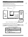
The figure below shows how the carriage position determines which ink system operation is to be
executed.
. . . . . . . . . . . . . . . . . . . . . . . . . . . . . . . . . . . . . . . . . . . . . . . . . . . . . . . . . . . . . . . . . . . . . . . . . . . . . . . . . -------i---:
; Printer mechanism
I
: (M-481O)
~ Cap/Pump
~ Mechanism
i~
. . . . . . . . .i..../ : ~
i ~:
:.
‘--------i
-. ------, ------------- i
i.;.... . .+. . . . . . . . . . . . . . . . . . . . . . . . . . . . . . . . . . . . . . . . . . . . . . . . . . - . . . . . . - - - --- ------Flashing #
Position ‘
i
I
ASF
Sheet loading
position
False absorbing ~
position
‘w
Cleaner end position
~“’’’sta”a”
‘------ Rubbing ~
Cleaner reset position ~
I
I
I
I
I
Ink catridge
Replacement
Position
Figure 2-20. Relation of Ink System Operation and
Carriage Position
2-18
(. ““
%-’
Ink system
Home po~ition (HP)
Rev. A
Opmeting Principles
STYLUS 800 Service Manual
2.4.1 Ink Operations
There are various ink operations that can be performed selectively by the printer.
2.4.1.1 Power on Operation
Power on consists of the following operations, and only one of these operations is performed,
depending on the position of the carnage when the printer is turned on.
■ At ink system home position
1) Moves the carriage to the flushing position and
performs the flushing operation.
2) Returns the carnage to the home position (standby for
printing).
Note:
N Notat ink system home position
The false absorbing operation ispetformedpreceding the above-mentioned sequence, depending
on the protect counter R value.
1) Returns the carriage to home position.
2) Performs cleaner blade- I operation.
3) Performs ink absorbing operation.
4) Performs pressure release operation.
5) Performs micro absorbing operation.
6) Performs false absorbing operation.
7) Performs cleaner blade-II operation (including the
flushing operation).
8) Moves the carriage to the standby position.
2.4.1.2 Cleaning Operation
This operation is performed when cleaning is selected by pressing the ALT and PAUSE buttons
simultaneously. There are three cleaning modes, each of which is selectively performed, depending
on the cleaning counter K value and the number of printed lines from the previous cleaning
operation.
■ CL1 (Normal)
■ CL2 (Intensive)
■ CL3 (False)
Rev. A
1) If the carriage is out of home position, return it to the home position.
2) Cleaner blade - I operation.
3) Change the gear engagement. (pump drive ON)
4) Ink absorbing operation.
5) Performs pressure release operation and micro absorbing operation.
6) Cleaner blade -II operation. (including the flashing operation)
7) Move the carnage to the stand-by position, and change the printer state to
the PAUSE state.
1) If the carriage is out of home position, return it to the home position,
2) Cleaner blade - I operation.
3) Change the gear engagement (pump drive ON)
4) Ink absorbing operation.
5) Pressure release operation.
6) False absorbing operation.
7) Rubbing operation.
8) Change the gear engagement. (pump drive ON)
9) Micro absorbing operation.
10) False absorbing operation.
11) Cleaner blade - II operation. (including the flashing operation)
12) Move the carriage to the stand-by position.
The same operation as CL1, except that the carriage is moved to the false
absorbing positionand the false absorbing operation is performed at step 4).
2-19
STYLUS 800 Service Manual
Operating Principles
2.4.1.3 Standby Operation
The standby operation prevents an increase in the viscosity of the ink held inside the printhead
nozzles. This operation is performed automatically if no data is received for more than three
seconds from the last print data.
1) Counts the number of flushing operations from the last standby operation, using the combined
print counter N. And performs the flushing based on the counter value.
2) Moves the carriage to the home position.
2.4.1.4 Initial Charge Operation
‘l%is operation, performed when initial charge mode is selected, charges the printhead with ink .
The operation has two modes, depending on the value held by protect counters B and C.
1) If the carriage is not at home position, returns it to home position.
■ Initial Charge
2) Performs cleaner blade - I operation.
3) Changes the gear engagement (pump drive on).
4) Performs ink absorbing operation (absorption= high).
5) Performs pressure release operation.
6) Performs ink absorbing operation (absorption= middle).
7) Performs pressure release operation.
8) Performs rubbing operation.
9) Performs micro absorbing operation.
10) Performs false absorbing operation.
11) Performs cleaner blade - II operation (including the flushing operation)
12) Moves the carriage to the standby position.
9 False Charge
This operation is identical with the initial charge operation, except that the
operations for steps 4) and 6) are changed as follows:
. Moves the carriage to the false absorbing position, and performs the false
absorbing operation. Then, moves the carriage to home position after step
8).
2.4.1.5 Refresh Operation
This operation prevents an increase in the viscosity of the ink inside the printhead, as well as to
eliminate any ink attached to the nozzle plate surface. Refresh consists of the following operations:
■ Refresh - I operation
■ Print start
■ False absorbing
2-20
This operation is activated by the REFRESH-I signal, which outputs
every 20 seconds during continuous printing.
1) Returns the carriage to home position.
2) Moves the carnage to the flushing position.
3) Performs flushing operation.
4) Performs cleaner blade-III operation (including the flushing),
based on the value of the combined print counter N.
5) Performs false absorbing operation, if the ink level counter R
value exceeds 5600.
6) Returns to the previous state.
This operation ejects high-viscosity ink inside the nozzles when the
printing starts from the standby state.
1) Moves the carriage to the flushing position and performs flushing.
2) Starts printing operation.
This operation absorbs ink inside the cap and eliminates ink
attached to the nozzle plate surface.
1) Moves the carriage to the false absorbing position.
2) Performs false absorbing operation.
3) Resets the pump pulley.
4) Release a mechanical pressure of the pump drive mechanism.
5) Adjusts the phase with paper feeding mechanism gears.
6) Returns the carriage to the home position.
Rev. A
. .
{.
STYLUS 800 Service Manual
Operating Principles
2.4.1.6 Cleaner Blade Operation
The cleaner blade operation eliminates any dust or ink attached to the nozzle plate surface. This
operation consists of the following separate operational modes.
This operation eliminates any dust attached to the nozzle plate surface before
the ink absorbing operation is performed.
1) Sets the cleaner blade.
2) Moves the carriage to the cleaner start position.
3) Moves the carriage to the cleaner end position (head surface is wiped off
with the cleaner blade).
4) Resets the cleaner blade.
5) Returns the carriage to the home position.
■ Cleaner blade -II This operation eliminates any dust or ink attached to the nozzle plate surface
after the ink absorbing operation is performed.
1) Sets the cleaner blade.
2) Moves the carriage to the cleaner start position.
3) Moves the carnage to the cleaner end position (head surface is wiped off
with the cleaner blade).
4) Resets the cleaner blade.
5) Moves the carnage to the flushing position and performs flushing.
6) Moves the carnage to the home position.
■ Cleaner blade - III This operation removes any dust or ink attached to the nozzle plate surface
during printing.
1) Sets the cleaner blade.
2) Moves the carriage to the cleaner start position.
3) Moves the carriage to the cleaner end position (head surface is wiped off
with the cleaner blade).
4) Resets the cleaner blade.
5) Moves the carnage to the flushing position and performs flushing.
6) Moves the carriage to home position.
This operation removes dust or ink that adheres to the head surface.
■ Rubbing
■ Cleaner blade - I
1) Sets the cleaner blade.
2) Moves the carriage to the cleaner start position.
3) Moves the carriage to the cleaner end position
(wiping = rubber side)
4) Moves the carriage to the flashing position
(wiping = felt side).
5) Moves the carriage to the home position. (This resets the cleaner blade.)
2.4.1.7 UC Replacement Operation
This operation is performed when the ink cartridge (1/C) is replaced.
Moves the carriage to the I/C replacement position.
Replace the ink cartridge.
Performs the cleaner blade-I operation.
Performs the ink absorbing operation with a selected absorption amount according to the ink
status of the previous I/C (ink end or ink low).
5) Performs the micro absorbing operation.
6) Performs the false absorbing operation.
7) Performs the cleaner blade-11 operation.
1)
2)
3)
4)
Rev. A
2-21
STYLUS 800 Service Manual
Operating Principles
2.4.1.8 Disengage ON Operation
This operation sets the switch lever to the position where it transmits the PF motor drive to the
pump mechanism.
{“’””
1) Moves the carriage to the position D where the lever is set to the specified position.
2) Moves the carriage to the position B.
3) Release a mechanical pressure of the paper feed drive mechanism. (Generates a backlash.)
4) Moves the carriage to the false absorbing position.
5) Adjusts the gear phase with the pump drive mechanism gears.
6) Moves the carriage to home position.
2.4.1.9 Micro Absorbing Operation
A small amount of air possibly gets into the ink path as a form of tiny bubble when the ink
cartridge is removed from the carriage after once it is installed. Such a small air bubble blocks the
ink path to obstacle an ink injection from the nozzle. This operation eliminates small air bubble
from the cavity of the printhead.
1) Performs the false absorbing operation.
2) Performs the micro absorbing operation.
,,.
(--
2.4.2 Counter and Timer
A..
EEPROM LE93C46 (IC1O) on the main board stores certain counter and timer values that are used
for control of the ink system operation.
2.4.2.1 Refresh - I Timer
This timer is used to prevent an increase in viscosity of the ink inside the nozzle. It counts every30
seconds during the printing operation. It resets when:
9 the flashing operation completes preceding a printing.
■ the refresh - I operation completes.
2.4.2.2 Flushing Counter
The flushing counter consists of the following counters.
■ Ink level counter R
This counter indicates the amount of ink that exists in the cap, in
proportion to the number of flushing operations. When the counter
value exceeds or equals 5600 (R 2 5600), the printer performs the
false absorbing operation.
I Combined print counter N This counter is used to: 1) keep a wet condition inside the cap, 2)
perform the wiping operation regularly to remove dust or ink that is
attached to the head surface. The “operations activated by this
counter differ for 1) and 2) as follows:
1) The flushing operation is performed based on the counter N value
at the flushing position, when the printer is in the standby state.
2) Wiping is performed when counter N value is equal to an integral
multiple of 60.
2.4.2.3 CL Counter K
This counter is used to switch cleaning operation mode, to prevent an excessive ink drainage. The
counter value is changed when CL1 or CL2 cleaning operation is performed.
2-22
Rev. A
~.,---- .,
STYLUS 800 Semice Manual
Operating Principles
2.4.2.4 Protect Counter
There are four protect counters to manage the amount of ink draining to the waste ink drain tank. The
value of these counters is stored in EEPROM on the main board upon power off.
t ■ Prot@ counter A
I
I
This counter is used to manage the total amount of drained ink. If the
counter value is equal to or exceeds 25000 (A 2 25000), the printer
indicates the error on the contiol panel and maintenance is required.
protect counter B
This counter prevents excessive ink drainage to the waste ink drain tank
by limiting the total number of the initial charge operations. If the
operation is selected when the counter value is equal to or exceeds 10
(B 2 10), the printer only performs the false charging operation.
■
■ Protect
■ ~k
counter C
counter R
Rev. B
This counter is used to prevent a continual initial charge operation. If the
operation is selected while the counter value is 1 (C=l), the printer only
performs the false charging operation.
‘.
This counter counts the amount of ink inside the cap.
2-23
Chapter 3
Disassembly and Assembly
Table of Contents
3-1
3.1 OVERVIEW
3.1.1 Precautions for Disassembling the Printer . . . . . . . . . . . . . . . . . . . . .. ...3-1
3-2
3.2 DISASSEMBLY AND ASSEMBLY
3.2.1 CASE, UPPER Removal . . . . . . . . . . . . . . . . . . . . . .................3-3
3.2.2 Power Supply Unit (C106 PSB/PSE BOARD) Removal . .............3-4
3.2.3 Main Controller (C106 MAIN BOARD) Removal . ...................3-5
3.2.4 PRINTER MECHANISM (M-481O) Removal . . . . . . . . . . . . . . . . . . . . .. .3-6
3.2.5 PRINTER MECHANISM Disassembly . . . . . . . . . . . . . . . . . . . . . .......3-7
3.2.5.1 PRINTHEAD UNIT Removal-. . . . . . . . . . . . . . . . . . . . . . .......3-7
3.2.5.2 PUMP UNIT Removal . . . . . . . . . . . . . . . . . . . . . .............3-9
3.2.5.3 CLEANER, HEAD Replacement . . . . . . . . . . . . . . . . . . . . .....3-11
3.2.5.4 CARRIAGE UNIT Removal . . . . . . . . . . . . . . . . . . . . . . . . . . . . 3-12
3.2.5.5 CR MOTOR Removal . . . . . . . . . . . . . . . . . . . . . . . . . . . . . . . . 3-13
3.2.5.6 PF MOTOR Removal . . . . . . . . . . . . . . . . . . . . . . . . . . . . . . . . . 3-14
3.2.5.7 PAPER FEED ROLLER ASSEMBLY Remova . . . . . . . . . . . . . . . 3-15
List of Figures
Figure 3-1. Disassembly Flowchart . . . . . . . . . . . . . . . . . . . . . ..............3-2
Figure 3-2. CASE, UPPER Removal . . . . . . . . . . . . . . . . . . . . . .............3-3
Figure 3-3. POWER SUPPLY UNIT Removal . . . . . . . . . . . . . . . . . . . . . ......3-4
Figure 3-4. MAIN CONTROLLER Removal . . . . . . . . . . . . . . . . . . . . . ........3-5
Figure 3-5. PRINTER MECHANISM (M-481O) Removal . ..................3-6
Figure 3-6. PRINTHEAD UNIT Removal . . . . . . . . . . . . . . . . . . . . . ..........3-7
Figure 3-7. PRINTHEAD UNIT Removal (Continued) . . . . . . . . . . . . . . . . . . . . .3-8
Figure 3-8. PUMP UNIT Removal . . . . . . . . . . . . . . . . . . . . . ...............3-9
Figure 3-9. PUMP UNIT Removal (Continued) . . . . . . . . . . . . . . . . . . . . .. ...3-10
Figure 3-10. CLEANER, HEAD Replacement . . . . . . . . . . . . . . . . . . . . . .....3-11
Figure 3-11. CARRIAGE UNIT Removal . . . . . . . . . . . . . . . . . . . . . . . . . .....3-12
Figure 3-12. CR MOTOR Removal . . . . . . . . . . . . . . . . . . . . . . . . . . . . . .....3-13
Figure 3-13. PF MOTOR Removal . . . . . . . . . . . . . . . . . . . . . . . . . . . . . . .....3-14
Figure 3-14. PAPER FEED ROLLER ASSEMBLY Removal . . . . . . . . . . .....3-15
Rev. A
3-i
STYLUS 800 Service Manual
Disassembly and Assembly
3.1 OVERVIEW
This section describes procedures for disassembling the main components of this printer. Unless
otherwise specified, the disassembled unit or components can be reassembled simply by reversing
the disassembly procedure. The assembly procedure is, therefore, omitted. Precautions for any
disassemble
are titles “~sassemblY/As*mblY points”. Adjustments
.
, or assemblv. Procedure
required after assembling the unit are titled “Required Adjustrn&ts”. -
3.1.1 Precautions for Disassembling the Printer
Refer to the precautions below when disassembling the printer.
H Disconnect the power cable before disassembling or assembling the printer.
H Wearprotectivegoggles to protect youreyesfiom ink. Ifinkgets in your eyes, wash it
away withfiesh water and see a doctor immediately.
If the ink comes into contuctwith skin (i.e, hands), wash it oflwith soap and water. If
irn”tation occurs, contact a physician.
■ Never remove the ink cartridge j?orn the carriage unless specified to do so.
■ When transporting the prhter afierinstalling the ink cati”dge, be sure to pack the
printer for transportation without removing the ink ca~”dge.
9 Use only recommended tools for disassembling, assembling, or adjusting the pn”nter.
■ Apply luti”cants and adhesives as specified. (See Chapter 6.)
H Make specified adjustments when you disassemble the printer. (See Chapter 4.)
Rev. A
3-1
STYLUS 800 Service Manual
Disassembly and Assembly
3.2 DISASSEMBLY AND ASSEMBLY
Follow the instruction in Section 3.1.1 to disassemble the prt”nter.
I
This section consists of the subheads shown in the diagram below. Refer to the exploded view of
the printer in the Appendix, if necessary.
F1
START
CASE, UPPER Removal
&
3.2.1
Page 3-3
Power Supply Unit
(C106 PSB/PSE) Removal
I
3.2.2
Page 3-4
I
v
Main Controller
(C106 MAIN) Removal
3.2.3
Page 3-6
I
I
Page 3-5
I
PRINTER MECHANISM
(M-4810) Removal
3.2.4
I
I
v
I
I
I
I
I
I
PUMP UNIT
Removal
3.2.5.2
Page 3-9
*
CLEANER, HEAD
Replacement
3.2.5.3
I
I
I
Page 3-11 I
*
CARRIAGE UNIT
Removal
3.2.5.4
I
Page 3-12
+
CR MOTOR
Removal
3.2.5.5
I
Page 3-13
+
PF MOTOR
Removal
H
3.2.5.6
Page 3-14
PAPER FEED ROLLER
ASSEMBLY Removal
3.2.5.7
Page 3-15
Figure 3-1. Disassembly Flowchart
3-2
Rev. A
STYLUS 800 Service Manual
Disassembly and Assembfy
3.2.1 CASE, UPPER Removal
[Step 1] Remove the COVER, PRINTER by releasing the tabs holding it to the CASE, UPPER.
[Step 2] Remove the SUPPORT, PAPER by releasing the tabs holding it to the CASE, LOWER.
[Step 3] Remove the GUIDE, PAPER, REAR.
[Step 4] Remove the CONTROL PANEL. (Release the tab by inserting a screwdriver into the hole
in the CASE, UPPER, as shown in figure below.)
[Step 5]
Remove 2 screws (CBB screw (M3 x 12) x 2).
[Step 6] Release 3 tabs by inserting a flathead screwdriver into the holes at the bottom of the
CASE, LOWER, as shown in figure below.
Holds the upper case firmly and pulling it as to remove, while you releasing the tabs.
[Step 7] Remove the CASE, UPPER by lifting the front side.
Cont~ol Panel
Figure 3-2. CASE, UPPER Removal
Rev. A
3-3
Disassembly and Assembly
STYLUS 800 Service Manual
3.2.2 Power Supply Unit (C106 PSB/PSE BOARD) Removal
[Step 1] Remove the CASE, UPPER. (Refer to Section 3.2.1.)
[Step 2] Disconnect the cables from comectors CN1 and CN2 of the C106 PSB/PSE BOARD.
,:,,
.(
[Step 3] Remove 4 screws (CBB screw (M3 x 6) x 2, CBS screw (M3 x 6), CB(0) screw (M4 x 8))
fixing the power supply unit to the lowercase, as shown in figure below.
[Step 4] Push in the locking tab and take out the power supply unit by sliding it toward the back
of the printer.
(.,. . ‘
Figure 3-3. POWER SUPPLY UNIT Removal
3-4
Rev. A
STYLUS 800 Service Manual
Disassembly and Assembly
3.2.3 Main Controller (CI06 MAIN BOARD) Removal
[Step 1]
[Step 2]
[Step 3].
Remove the CASE, UPPER. (Refer to Section 3.2.1.)
Disconnect the cables from the connectors CN2/CN3/CN4/CN5 /CN6/CN7 of the C106
MAIN BOARD.
Remove 4 screws (CBB screw (M3x1O)X2,CBS screw (M3x6)x2) and take out the main
controller.
.
I
I
I
I
I
I
I
I
I .
■
■
■
When you replace the main board, initialize the EEPROM contents as follows:
Reassemble the printer.
1)
Turn the printer ON while hold down IALTI, IECONOMYICONDENSED1,
2)
fLOADIEJECll and [PAUSEI buttons on the control panel.
When you replace the main boani to new one, you must take out the block resistor attached
at the location RM22 of old main board, and this block n%stor should be attachsd to the new
board in hrder to maintain proper printhead drive voltage control.
When you replace the main board to new one, tti waste ink absorbing materials must be
replaced at the same time.
CN2,3
CBB(M3X1O)
13 S(M3X6)
ntroller
Figure 3-4. MAIN CONTROLLER Removal
I Bi-Directional Printing Alignment Adjustment (Chapter 4, Section 4.2)
I Default Setting Parameter Refl”stration (Chapter 4, Section 4.3)
h
Rev. B
I
3-5
Disassembly and Assembly
STYLUS 800 Service Manual
3.2.4 PRINTER MECHANISM (M-481O) Removal
[Step 1]
[Step 2]
[Step 3]
[Step 4] .
[Step 5]
■
m
Remove the CASE, UPPER. (Refer to Section 3.2.1.)
Remove the power supply unit. (Refer to Section 3.2.2.)
Remove the main controller. (Refer to Section 3.23.)
Move the carriage to the center of the ptiner.
Remove 4 screws (CB screw (M4x16)x4) and take out the printer mechanism.
Wipe ofl any. ink attached around the end of the ink drain tube, when you removed the
machanism.
When reinstall the print& mechanism, check that the waste ink drain tube is properly inserted
into a space between the lower case and the waste ink absorbing matert”al.
.4810)
Figure 3-5. PRINTER MECHANISM (M-481O) Removal ‘
When the printhead or the printer mechanism is replaced, the block msistormust be replaced at location
RM22 on the main controller board. (Eve~ spare printhead or spare printer mechanism is come with
a block resistor that specifically selected to each printheadt to ensuw opti”mal control of the dn”ver
circuit.)
Alignment Adjustment (Chapter 4, Section 42)
3-6
1
Rev. B
Disassembly and Assembly
SNLUS 800 Servke Manual
3.2.5 PRINTER MECHANISM Disassembly
The procedures described in this section explain removal of components within the printer
mechanism.
3.2.5.1 PRINTHEAD UNIT Removal
[Step 1] Remove the printer mechanism. (Refer to section 3.2.4.)
[Step 2] Move the carriage to the middle of the printer. The carriage is located between first and
second paper guide roller, as illustrated in figure below. Pull the ink cartridge clamp
towards you and remove the ink cartridge.
[Step 3] Release the tabs holding thecarnagecover (4 tabs), andtakethe cover off.
[Step4] Remove thetension barthatholds theprinthead Unitinplace.
[Step5] Discomect the cables from the printhead unit (the FPC cables from connectors CN2 and
CN3, and the cable from connector CN1), and remove it.
A
~
9 Take a proper measurement to protect a printhead unitflom static-electi”city, since the
driver IC is directly atiached on the printhead unit.
■ Never touch the nozzle surface and a metallic cover of the printhead. Handle it by only
holding the edges of the printhead.
■ When the ~“nthead or the printer mechanism is replaced, the block resistor must be
replaced at location RM22 on the C106 MAIN BOARD. (Every spare printhead or spare
printer mechanism is come with a block resistor that specifically selected to each
printhead, to ensure optimal control of the driver circuit.
1 L
Figure 3-6. PRINTHEAD UNIT Removal “
Rev. A
3-7
STYLUS 800 Service Manual
Disassembly and Assembly
Ink Cartridge
o
0“
Q
I
@
Printhead Unit
a
-.
22%
=’5”
~
%..
\
/
Figure 3-7. PRINTHEAD UNIT Removal (Continued)
3-8
Rev. A
..:-.
f,.
SNLUS 800 Sewice Manual
Disassembly and Assembly
3.2.5.2 PUMP UNIT Removal
[Step 1] Remove the PRINTER MECHANISM. (Refer to section 3.2.4.)
[Step 2] Move the carriage to the middle of the printer. The carriage is located between first and
second paper guide roller, as illustrated in figure below.
[Step 3] Remove 2 screws (CBB screw (M3 x 10) x 2) fixing the front paper guide assembly to the
mechanism.
[Step 4] Lift the front side of the carriage and hold it. Then, lift the left end of the front paper guide
assembly slightly, and then lift the right end. Take out the front paper guide assembly by
pulling it toward you.
[Step 5] Insert a piece of paper between the printhead and the printer mechanism to protect the
surface of the printhead from being damaged.
[Step 6] Push the pump unit inward by releasing the tab securing the pump unit to the holder
plate while releasing the tab at the bottom of the pump unit. Then, take the pump unit out
of the printer mechanism.
‘\
Guide Assembly
)
Figure 3-8. PUMP UNIT Removal
Rev. A
3-9
STYLUS 800 Sewice Manual
Disassembly and Assembly
f
Pump Unit
,*-
4.
Figure 3-9. PUMP Unit Removal (Continued)
3-1o
Rev. A
STYLUS 800 Service Manual
Disassembly and Assemb/y
3.2.5.3 CLEANER, HEAD Replacement
[Step 1] Remove the PUMP UNIT. (Refer tosection3.2.5.2.)
[Step 2] Remove the CLEANER, HEAD from the pump unit.
Keeping the CLEANE& HEAD clean is extremely important to keep the ink injection
system working properly in the printhead, and it directly afiects printing quality.
Therefore, handle the CLEANER, HEAD vey carejidly, and observe the following
instructions.
~ Never touch the CLEANER, HEAD with your bare hands.
N When attaching the CLEANER HEAD to the pump unit, weargloves and use clean
tweezers to handle it.
CLEANER, HEAD
Ca
CLEANER, HEAD
Slit
Uu
E?
Hook the CLEANER, HEAD to
the cap unit by turn up the part of it.
Figure 3-10. CLEANER, HEAD Replacement
Dkassembly and Assembly
STYLUS 800 Servke Manual
3.2.5.4 CARRIAGE UNIT Removal
@
[Step 1] Remove the printer mechanism. (Refer to section 3.2.4.)
[Step 2] Remove the tension spring that holds the CR motor in place. Then, take the timing belt
out of the CR motor drive pulley and the driven pulley.
[Step 3] Remove the ground spring plate on the left side.
[Step 4] Rotate the HOLDER, SHAFT that holds both ends of the carriage guide shaft, and push
the ends inward to disengage them from the left and the right frame of the printer
mechanism.
[Step 5] Remove the FPC cables that go through the base frame assembly.
[Step 6] Remove the carriage unit along with the carriage guide shaft.
HOLDER, SHAFT
.,
(
v
,.,
f
.
Figure 3-11. CARRIAGE UNIT Removal
Paper
Gap Adjustment (Chapter 4, Section 4.4)
I
.
3-12
Rev. A
’.,.
“
,.,
STYLUS 800 Sewice Manual
Disassembly and Assembiy
3.2.5.5 CR MOTOR Removal
[Step 1] Remove the printer mechanism. (Refer to section 3.2.4.)
[Step 2] Remove the tension spring and take thetimingbeltout of the CRmotordrive pulley.
[Step3] Remove 3 screws (CP(P2) screw (M3 x 10) x 3) that fixing the CR motor to the CR motor
holder plate, and remove the CR motor.
CP(P2)(M3XIO)
Figure 3-12. CR MOTOR Removal
Rev. A
3-13
Disassembly and Assembly
STYLUS 800 Service Manual
3.2.5.6 PF MOTOR Removal
[Step 1] Remove theprinter mechanism. (Refer tosection3.2.4.)
[Step 2] Remove3 screws (CBB screw (M3x 10) x3), and remove theholdingplate.
Since the holding plate retains the pressure springs under it, be sure not to loose them when
removing the holding plate.
[Step3] Removea screw (CBBscrew (M3x IO)), and remove the PFMOTOR.
10)
,.,,
{. .
Figure 3-13. PF MOTOR Removal
$
,,,.
‘k
3-14
Rev. A
STYLUS 800 Service Manual
Disassembly and Assembly
3.2.5.7 PAPER FEED ROLLER ASSEMBLY Removal
[Step 1] Remove the printer mechanism. (Refer to section 3.2.4.)
[Step 2] Remove the carriage unit. (Refer to section 3.2.5.4.)
[Step 3] Remove 2 screws (CBB screw (M3 x 10) x 2), and remove the frame assembly.
[Step 4] Remove the PAPER FEED ROLLER ASSEMBLY.
CBB(M3X1 o)
P
+5&q “
d.
1+/
k
\@k#-
.
x
Paper Feed Roller Assembly
Figure 3-14. PAPER FEED ROLLER ASSEMBLY Removal
Paper Gap Adjustment (Chapter 4, Section 4.4)
Rev. A
I
3-15
Chapter 4
Adjustments
Table of Contents
4-1
4.1 OVERVIEW
4.1.1 Precautions for Adjustment . . . . . . . . . . . . . . . . . . . . . . . . . . . . . . . . . . . . 4-1
4.2 BI-DIRECTIONAL PRINTING ALIGNMENT ADJUSTMENT
4-1
4.3 DEFAULT SEITING PARAMETER REGISTRATION
4-2
4.4 PAPER GAP ADJUSTMENT
4-2
List of Figures
Figure 4-1. PG Adjustment . . . . . . . . . . . . . . . . . . . . . . . . . . . . . . . . . . . . . . . . . .4-3
List of Tables
Table 4-1. Gap and Adjustment Direction . . . . . . . . . . . . . . . . . . . . . .........4-2
4-i
STYLUS 800 Service Manual
Adjustment
4.1 OVERVIEW
This section describes procedures of the adjustment required when the printer is disassembled and
assembled after repair.
4.1.1 Precautions for Adjustment
You should refer to the precautions below when adjusting the printer.
Disconnect the power cable before when you attempt the adjustment. (Unless otherwise
specified.)
4.2 BI-DIRECTIC)NAL PRINTING ALIGNMENT ADJUSTMENT
The bidirectional printing alignment adjustment is required when the printer mechanism or the
main board is replaced. By performing this adjustment, a compensation value is determined for the
mechanical control as to compensate the deviation of print position, which may be caused by the
different print speeds due to the tolerance of the mechanical components, and the deviation of print
timing between odd-numbered lines and even-numbered lines in bidirectional printing. The
printer stores the compensation data in the EEPROM on the main board (C106 MAIN), and
referring to this data when the bi-directional printing is performed.
[Step 1] Set a stack of paper into the auto sheet feeder of the printer.
[Step 2] Comect the PC to the printer and turn the both units on.
[Step 3] Execute BASIC on the PC and start the adjustment program “DNxxx.BAS”.
[Step 4] When the main menu of the program is appeared on the monitor, select “Bi-D Printing
Alignment” by entering “l”.
[Step 5] Follow the instruction displayed on the monitor, and press ENTER key to start the
adjustment.
[Step 6] The printer prints the check pattern with a sample compensation value.
[Step 7] Check the printed sample pattern, and if the character “H” is not vertically aligned in both
odd-numbered lines and even-numbered line, enter the compensation value in the range
from -30 to +30, from the keyboard.
■ Positive compensation value:
Shift 2nd line to LEFT
■ Negative compensation value:
Shift 2nd line to RIGHT
[Step 9] The printer print the sample pattern with the selected compensation value for
confirmation. If the alignment is good, press “Y’ to finish the adjustment.
[Step 10] Terminate theprogramby selecting ’’3”at the main menu, and turn theprinteroff.
Because the compensation value specified within this program is not valid until the printer is
turned off, turn the printer off immediately after you have finish the adjustment.
Rev. A
4-1
STYLUS 800 Sewice Manual
Adjustment
4.3 DEFAULT SETTING PARAMETER REGISTRATION
The set up value that specifies the destination of the product distribution, is stored in the EEPROM
on the main board (C106 MAIN). Therefore, this set up value must be written in EEPROM when the
main board or the EEPROM chip is replaced.
[Step 1] Comect the PC to the target printer and turn the printer on.
[Step 2] Execute BASIC on the PC and run the program “DNxxx.BAS”.
[Step 3] When the main menu appeared, choose “Default Setting Parameter Registration” by
entering “2” from the keyboard.
[Step 4] When the next menu appeared, press ‘Y” and enter key and the program transfer the
default setting parameters to the printer.
[Step 5] Press ‘Y” and enter key to return to main menu. Transferred setting parameters are stored
in EEPROM when the printer is turned off.
4.4 PAPER GAP ADJUSTMENT
When the printer mechanism is disassembled to remove and/or replace the carnage unit, the
distance between the printhead and a paper surface (Paper gap) should be adjusted to 1.0 mm, to
ensure the print quality.
[Step 1] Attach thepapergap (PG) gauge attheleftside adjust position shown in figure below, as
the top edge of gauge contacts a support plate of FRAME ASSEMBLY, BASE.
[Step2] Move the carriage to the position where the PG gauge is attached, while lifting up the
front edge of the carriage as to widen the gap between the printhead and the mechanism.
[Step3] Carefully put the carriage on the PG gauge and verify that there is a gap between the
front edge of the carriage unit and the front frame.
Table 4-1. Gap and Adjustment Direction
Gap between Carriage and Front Frame
LEH’ Bush
RIGHT Bush
Yes
Cw
Ccw
Ccw
Cw
(Gap exist between p~~head and PG gauge)
[Step 4] Rotates BUSH, PARALLEL, ADJUST that attached at the left end of the carnage guide
shaft as the printhead contact the PG gauge. When you narrow the gap and the printhead
contacts the PG gauge, the front edge of the carriage unit pop up and if so, moves the
bush 1 step in reverse direction.
[Step 5] Remove the PG gauge and attach it at the right side adjust position.
[Step 6] Repeat the step from [Step 2] to [Step 4], and adjust the gap with BUSH, PARALLEL,
ADJUST at the right end of the carriage guide shaft.
[Step i’1 Verify the gap at the left adjust position, as if the front edge of the carriage unit pop up
when you move the left end bush 1 step in counter-clockwise (CCW).
4-2
Rev. A
Adjustment
STYLUS 800 Service Manual
Shaft holder
Carriage guide shaft
T
I
Ii
........
I~
I
““-7L
6’
Ii
::
1:
.. ;....:
I
A
\
LEH
Adjust position
Shaft holder
\
4
PG Gauge
RIGHT
Adjust position
..........................................................
7
arriaga
/
Pnnthead
/
n
PG Gauge
Cut section (A-A’)
Figure 4-1. PG Adjustment
Rev. A
4-3
Chapter 5
1
Troubleshooting
Table of Contents
5-1
5.1 OVERVIEW
5-3
5.2 UNIT LEVEL TROUBLESHOOTING
5.2.1 Printer does not operate at power on . . . . . . . . . . . . . . . . . . . . . . .......5-4
5.2.2 Error is detected . . . . . . . . . . . . . . . . . . . . . . . . . . . . . . . . . . . . . . . . . . .. .5-5
5.2.3 Failure occurs during printing . . . . . . . . . . . . . . . . . . . . . . .............5-6
5.2.4 Printer does not feed the paper correctly . . . . . . . . . . . . . . . . . . . . . . . .. .5-7
5.2.5 Control panel operation is abnormal . . . . . . . . . . . . . . . . . . . . . . . ......5-8
5.3 UNIT REPAIR - C106 PSB/PSE BOARD
5“9
5.4 UNIT REPAIR - C106 MAIN BOARD
5-1o
5.5 UNIT REPAIR - PRINTER MECHANISM (M-481O)
5-12
List of Figures
Figure 5-1. Troubleshooting Process Flowchart . . . . . . . . . . . . . . . . . . . . .. ...5-1
List of Tables
Table
Table
Table
Table
Table
Table
Table
Rev.A
5-1.
5-2.
5-3.
5-4.
5-5.
5-6.
5-7.
Motor Resistance . . . . . . . . . . . . . . . . . . . . . . ..................5-1
Sensor Status . . . . . . . . . . . . . . . . . . . . . . . . . . . . . . . . . . . . . . . . .. .5-1
Error Codes . . . . . . . . . . . . . . . . . . . . . . . . . . . . . . . . . . . . . . . . .. ...5-2
Symptom and Problem . . . . . . . . . . . . . . . . . . . . . ...............5-3
Repair of C106 PSB/PSE Board . . . . . . . . . . . . . . . . . . . . . ........5-9
Repair of the C106 MAIN . . . . . . . . . . . . . . . . . . . . . . . . . . . . .....5-10
RepairofPrinter Mechanism . . . . . . . . . . . . . . . . . . . . . . . . . . .....5-12
Si
STYLUS 800 Service Manual
Troubleshooting
5.1 OVERVIEW
The printer may exhibit different symptoms for the same problem, which makes troubleshooting
more difficult. This section, however, provides simple and effective ways to facilitate
troubleshooting. The following flowchart illustrates the main steps of the troubleshooting process.
J
I
ASSEMBLY
AND
ADJUSTMENT
(
I
-1
I
END
Figure 5-1. Troubleshooting Process Flowchart
Table 5-1. Motor Resistance
Motor
Resistance
Remark
CR Motor
10.0 !2 f 7% / Phase
At25‘C
PF Motor
54.0 Q + 3 Cl I Phase
At 25 “C
Table 5-2. Sensor Status
Sensor
Rev. A
Point
PE Sensor
CN4 / Pin 1
HP Sensor
CN3/ Pin 10
Signal Level
H (5V)
status
Paper exist
L (GND)
No paper (Paper end)
H
At home position (HP)
L
Out of HP
5-1
STYLUS 800 Service Manual
Troubleshooting
Table 5-3. Error Codes
PAPER
LED
Error
INK END
LED
PAUSE
LED
Paper out
ON
OFF
OFF
Paper jam
BLINKS
OFF
OFF
Ink low *1
OFF
BLINKS
-
Ink end
OFF
ON
OFF
No ink cartridge
OFF
ON
OFF
Carriage Error
OFF
OFF
OFF
Waste ink tank
over-flow
Notes: V :
4 :
OFF
ON
V* ~ ~ tim~
V* x 3 times
No beeps
BLINKS
4 :
0.1 second beep
0.1 second interval + :
Buzzer
Recovery
Load the paper and press the
buttons as follows:
1. PAUSE
2. LOAD/EJECT
Same as above.
Press PAUSE button and
replace the ink cartridge with
a new one. Then, press
PAUSE button again to
resume printing. ● 2
V* ~ s times
Replace the ink cartridge and
press PAUSE button.
v+ ~ ~ times
Install the ink cartridge and
press PAUSE button.
*+ ~ ~ ~imes
Turn off the printer, and turn
it on again.
V* x 3 times
Service maintenance
required. (Replace the waste
ink absorbing materiil and
reset the protect counters.)
0.5 second beep
0.2 second interval
*1: This is not treated as an error.
*2: It is not necessary to replace the ink cartridge until the printer detects the ‘Ink
End’ error.
5-2
Rev. A
(’
.&.
x
Troubleshooting
STYLUS 800 Service Manual
5.2 UNIT LEVEL TROUBLESHOOTING
When a problem occurs, you can distinguish the defective unit by referring the symptoms of the
defect. The table below lists the svrrmtom of certain defects, and you can easily identify what the
problem. Once the problem is identif&i, refer to the flowchart corresponding to each problem.
Table 5-4. Symptom and Problem
Symptom
Problem
Flowchart No.
Printer does not operate at
power on
■ LED do not light up.
■ Printer mechanism do not operate.
5.2.1
Error is detected
■ Error is indicated by LED or buzzer
5.2.2
Failure occurs during printing
■ Printing is not performed.
■ Abnormal printing (missing dots, etc.)
■ Print quality is poor
5.2.3
Printer does not feed the
paper correctly
■ No paper is fed.
■ Paper feed is irregular.
H Paper jam occurs.
5.2.4
Control panel operation is
abnormal
■ No response to button access.
5.2.5
Rev. A
5-3
STYLUS 800 Service Manual
Troubleshooting
5.2.1 Printer does not operate at power on
d“’
y
.. .
F
Use the comxt
YES
Replace the fuse
and discmwt
cN70n the C106
MAIN board..
NO
NO
Check the output
voltage of Ihe C1C6
PWPSEal CN2.
YES
I
w
Replaca the
CIOS PSSJPSE
board.
I
... ,
Replace the
printer mechanism.
YES
t.
4
END
*
1
,
..
5-4
Rev. A
TmuMeshootjng
STYLUS 800 Sewke Manual
5.2.2 Error is detected
START
Identify the type
of enor indicated.
(SaeTable 5-3.)
z
Turn the printer
NO
NO
NO
Waste ink drain
tank over-fbw
r
Replace the waste
ink absorbing
material, and raset
the protect counter.
(S88 Chapter 6.)
NO
4
YES
NO
Replamthe printer
mechanism.
+-
Rev. A
ND
END
*
*
5-5
STYLUS 800 Service Manual
Troubleshooting
5.2.3 Failure occurs during printing
#-:
F
““f
. “.
NO
YEs
J
NO
NO
{,:.;’”
Adjust the
Bkdirectionel
ES
Es
NO
NO
ES
I
Reptecethe
printer mechanism.
NO
R@cetheC106
MAIN bcaNI.
I
F
Es
END
END
*
+
.
5-s
Rev. A
Troubleshooting
STYLUS 800 Service Manual
5.2.4 Printer
does not feed the paper correctly
NO
YES
NO
G
Replace the C1G6
MAIN board.
YES
END
*
Rev. A
Set the paper
Ccmcfly.
I
Verify that nothing
abnormal within
the paper path.
Also confirm that
there is nci any
foreign objects
that may interfare
the paper
movement,
Replace the
printer mechanism.
END
*
S-7
STYLUS 800 Servjce Manual
Troubleshooting
5.2.5 Control panel operation is abnormal
m
YES
&
Is the
prcblem
corrected ?
YES
NO
d
c,
Replace the
ccntrol panel.
NO
Replacatha C106
YES
MAIN board.
END
*
. .. . .
f,.
.
5-s
Rev. A
STYLUS 800 Sewice Manual
Troubleshooting
5.3 UNIT REPAIR - CI06 PSB/PSE BOARD
This section describes the problems related to the power supply board (C106 PSB/PSE). The table
below provides various symptoms, likely causes, and checkpoints. The checkpoints refer to
waveforms, resistance, and other values to be checked to evaluate the operation of each component.
Table 5-5. Repair of C106 PSB/PSE Board
Rev. A
5-9
STYLUS 800 Service Manual
Troubleshooting
5.4 UNIT REPAIR - CI06 MAIN BOARD
This section describes the problems related to the main controller board (C106 MAIN). The table
below provides various symptoms, likely causes, and checkpoints. The checkpoints refer to
waveforms, resistance, and other values to be checked to evaluate the operation of each component.
c ‘a
Table 5-6. Repair of the C106 MAIN
-. :.,.,
f., .,.
5-1o
Rev. A
STYLUS 800 Service Manual
Troubleshooting
Table 5-6. Repair of the C106 MAIN (Continued)
Rev. A
5-11
SNLUS 800 Service Manual
Troubleshooting
5.5 UNIT REPAIR - PRINTER MECHANISM (M-4810)
Troubles related to the printer mechanism should be repaired according to the troubleshooting
procedures in Table 5-7.
Table 5-7. Repair of Printer Mechanism
Symptom
Condition
Cause
Foreign
substances are
Checkpoint
Manually drive the gear
Solution
Remove any
mechanism
fails to rotate at
lodged in the gear
train conneoted to the
foreign
pump meohanism to check sub~ance
does not
operate.
time of power
on.
in the mechanism.
if the motor rotates.
The PF motor is
defective.
Check the coil resistance
of the motor.
Replace the
PF motor.
The tube is not
properly
connected to the
cap.
Check that the tube is
properly connected to the
cap.
Set the tube
properly.
The ink tube is
damaged.
Replace the
Cheek the ink tube visually. tub
The cap is
defective.
Cheek for any defective
part.
The pump is
defective.
Replace the pump to see if
Replace the
this causes the ink to be
pump unit.
absorbed normally.
The printhead is
defective.
Replace the printhead to
see if this oauses the ink
to be absorbed normally.
Replace the
printhead.
Foreign
substances are
lodged in the gear
in the mechanism.
Manualty drive the timing
belt to see if the carriage
motor ~tates
Remove any
foreign
substance.
The carriage
motor is defective.
Measure the coil
Replace the
resistance of the CR motor. csrriige motor.
The pulley is
defective.
Cheek for broken or worn
pulley.
Replace the
driien pulley.
Check that the timing belt
is properly inserted into
the bottom of the carriage.
Reinsert the
timing belt.
Check the timing belt for
any darnage.
Replace the
timing belt.
Check whether the
carriage moves smoothly
when moved manually.
Clean and
lubricate.
Check tension of the
timing bett.
Adjust tension
of the timing
belt.
The pump
Ink is not
absorbed or
poorly
absorbed.
The carriage
motor does not
rotate.
The PF motor
Used ink does
not go through
the used ink
tube during the
cleaning
operation.
The carriage
motor fails to
rotate at time of
power on.
The carriage
motor rotates,
but the carriage
The carriage
does not
Jperate
7ormally at time does not move”
3f power on.
~after the
>arriage has
]een manually
The carriage
:entered prior
moves slightly
o power on).
and then stops.
The timing belt is
defective.
Carriage
movement is not
smooth.
(----- ‘
Replace the
head cap.
,. ..-
(“
!.
. ,
5-12
Rev. A
I
‘\
Troubleshooting
SNLUS 800 Service Manual
Table 5-7. Repair of Printer Mechanism (Continued)
Symptom
Printing is not
performed.
Checkpoint
The head cable is
disconnected.
Check the head cable for
disconnection.
Replace the
cable.,
The printhead is
defective.
Replace the printhead to
see if the printhead
operates normally.
Replace the
printhead.
Ink absorption is
poor.
See “Ink is not absorbed”
on the previous page.
Printhead surface
is not clean.
Perform the cleaning
operation.
Clean.
The head cable is
disconnection.
Check the head cable for
disconnected.
Replace the
cable.
The printhead is
defeotive.
Replace the printhead.
Replace the
printhead.
Printhead surface
is not clean.
Check front of the
printhead.
Clean.
The expiration of
the ink oartridge.
Check the ink cartridge for
expiration.
Replace the
ink cartridge.
Cheek whether the cable
is properly plugged into
the connector.
Plug the oable
into the
conneotor
properly.
Cheek the cleanliness.
Clean.
The printhead is
defective.
Replace the printhead to
see if this causes printing
to be performed normally.
Replace.
Ink is lmorly
absorbed.
Check whether the used
ink goes through the used
ink tube.
See “Ink is not
absorbed”.
Printhead
characters are
not aligned.
The paper gap is
not adjusted.
Check the paper gap.
Adjust the gap.
The intervals
between the
characters are
irregular.
The timing bett is
defective.
Cheek that the timing belt
is properly inserted into
the bottom of carriage.
Set the timing
belt properly.
Vertical line is
not aligned.
Bidirectional
alignment is not
adjusted.
Adjust the check it with
bi-directional alignment
program.
Adjust the
bi-directional
alignment.
The carriage
moves, but no
printing is
performed.
A particular dot
is not printed.
Abnormal
printing.
A dot is not
printed
occasionally.
Insufficient
contact of the
head cable.
Foreign substance
Visually check the paper
are lodged in the
path.
paper path.
Paper is not fed
normally.
Rev. A
Solution
Cause
Condition
Paper is not fed.
Remove any
foreign
substance.
Replace
defective
gears.
Paper feeding
gears are
defective.
Visually check the gears.
The paper feed
motor is defective.
Replace the
Measure the coil
resistance of the PF. motor. PF motor.
5-13
Chapter 6
Maintenance
Table of Contents
6.1 PREVENTIVE MAINTENANCE
6-1
6-1
6.2 SERVICE MAINTENANCE
6.2.1 Printhead Cleaning . . . . . . . . . . . . . . . . . . . . . . . . . . . . . . . . . . . . . . . . .. .6-1
6.2.2 Waste Ink Drain Tank Replacement. . . . . . . . . . . . . . . . . . . . . . ........6-1
6-2
6.3 LUBRICATION
List of Figures
Figure 6-1. Lubrication Points . . . . . . . . . . . . . . . . . . . . . ..................6-3
List of Tables
Table 6-1. Recommended Lubricants . . . . . . . . . . . . . . . . . . . . . ............6-2
Table 6-2. Lubrication Points . . . . . . . . . . . . . . . . . . . . . ...................6-2
Rev. A
6-i
SNLUS 800 Service Manual
Maintenance
6.1 PREVENTIVE MAINTENANCE
Altough this printer is designed that no specific maintenance is required in regular basis, it is good idea
to clean the printer throughly whenever you get a chance to do so. You can clean :
a
■
■
1
Outer case
If it is dirty, clean it with a soft, clean cloth, dampened with mild detergent if necessary.
Auto sheet feeder
If the inside of the auto sheet feeder is dirty (dust), carefully brush away all dust and dirt
using a soft brush. If the pick up roller of the sheet feeder is dirty, clean its surface with
a soft, clean cloth.
Inside the printer
If you notice any dust or dirt accumulated inside the printer when you open the outer case
for repair, remove all dust and dirt using a vacuum cleaner.
■
Never use thinner, trichloroethyhme, or ketone-based solvents for cleaning. These chemicals can
dama~e the components of the vrinter.
■
Do not use a hard or abrw”ve bmsh for cleaning.
Be care)id not to damage the components of the printer when using the vacuum cleaner.
■
[
6.2 SERVICE MAINTENANCE
Certain maintenance is required wh& the printer detects an error or decline in print quality is observed.
6.1.1 Printhead Cleaning
If print quality deteriorates, clean the printhead using the built-in printhead cleaning function. The printer
also has automatic printhead cleaning cycle to ensure the proper nozzle operation for ink injection as well
as to preserve its best condition. Therefore, perform this printhead cleaning operation only if print quality
declines, in order to avoid wasting ink.
[Step 1]
Turn the printer on and press the PAUSE button to pause the printer. Make sure that the
PAUSE LED is on.
[Step 2]
Hold down the ALT button and press PAUSE button for two senconds.
When the panel switch operation is accepted by the printer, buzzer beeps and the cleanin g cycle starts.
It takes approx. 30 seconds to complete, and the PAUSE LED flashes during the cleaning cycle. When the
Cleaning completes, the PAUSE LED stop flashing.
I
I
I
I
I
I
I
I
I
I
I
Rev.B
6-1
Maintenance
STYLUS 800 Service Manual
6.3 LUBRICATION
The printer must be lubricated properly when the printer is disassembled for component
replacement, or if the mechanical noise exceeds a certain level. EPSON only recommends the
lubricants listed in table below for this printer, both of which have been tested extensively and
found to comply with the requirements of this printer mechanism. The figure on next page shows
the lubrication points.
,<f”!,
4
Table 6-1. Recommended Lubricants
Type
Name
QTY
Part No.
Availability
Oil
o-5
40 cc
1010513
E
Grease
G-26
40 g
B702600001
E
E= EPSON Exclusive product (Not commercially available)
Note)
Table 6-2. Lubrication Points
I
I
Ref. No.
Lubrication Point
(1)
Frame Assembly, R (Gear shaft A,B and C)
G-26 (1 -3 mg)
(2)
Flat gear, 8
G-26 (1 -3 mg)
(3)
Shaft, Reduotion
G-26 (1 -3 mg)
(4)
Oil Pad (Carriage)
O-5 (3 drops)
(5)
Shaft, CR, Guide
O-5 (Paint on the shaft)
(6)
Roller, PF
G-26 (1 -3 mg)
Lubricant
■ Do not apply too much lubricant, as it may cause a stain on the mechanism as well as a
malj%nction of the mechanism.
,
,..
‘1
SNLUS 800 Service Manual
Maintenance
Figure 6-1. Lubrication Points
6-3
Rev. A
I
Appendix
Table of Contents
A.1 CONNECTOR SUMMARY
A-1
A.2 CIRCUIT DIAGRAMS
A-5
A.3 CIRCUIT BOARD COMPONENT LAYOUT
A-9
A-12
A.4 EXPLODED DIAGRAM
List of Figures
Figure A-1. Interconnection of Major Components . . . . . . . . . . . . . . . . . . . . . . A-1
Figure A-2. CI06 MAIN Control Board Component Layout . . . . . . . . . . . . . . . . A-9
Figure A-2’. C106 MAIN-B Control Board Component Layout . . . . . . . . . . . . . . A-9’
Figure A-3. C106 PSB/PSE Power Supply Board Component Layout . . . . . . A-10
Figure A-3’. C106 PSB-B/PSE-B Power Supply Board Component Layout . . A-10’
Figure A-4. Cl 06 PNL Control Panel Board Component Layout . . . . . . . . . . . A-1 1
Figure A-5. Stylus 800 Exploded Diagram (1) . . . . . . . . . . . . . . . . . . . . . . . . . A-12
Figure A-6. Stylus 800 Exploded Diagram (2) . . . . . . . . . . . . . . . . . . . . . . . . . A-13
List of Tables
Table A-1. Connector Summary . . . . . . . . . . . . . . . . . . . . . . . . . . . . . . . . . . . . . A-2
Table A-2. Connector Pin Assignment - CN1 . . . . . . . . . . . . . . . . . . . . . . . . . . . A-2
Table A-3. Connector Pin Assignment - CN2 . . . . . . . . . . . . . . . . . . . . . . . . . . . A-2
Table A-4. Connector Pin Assignment - CN3 . . . . . . . . . . . . . . . . . . . . . . . . . . . A-3
Table A-5. Connector Pin Assignment - CN4 . . . . . . . . . . . . . . . . . . . . . . . . . . . A-3
Table A-6. Connector Pin Assignment - CN5 . . . . . . . . . . . . . . . . . . . . . . . . . . . A-3
Table A-7. Connector Pin Assignment - CN6 . . . . . . . . . . . . . . . . . . . . . . . . . . . A-3
Table A-8. Connector Pin Assignment - CN7 . . . . . . . . . . . . . . . . . . . . . . . . . . . A-4
Rev. D
A-i
Appendix
SNLUS 800 Sewice Manual
A.1 CONNECTOR SUMMARY
Figure below shows the intercomection between the major components of the Stylus 800.
AC
+11
c-)
Input
CI06 PSB/PSE
z_
ICN2 I
.....................................................
Iw-1
Parallel
IIF
Printhead
Unit
OJ
z
—~
i
HP
Sensor
. o
z . .......
I
I CN8 ]
I CN6 ]
E
PE
Sensor
ICN5 ~
I - Ap’”o’or
-n
CR Motor
Printer Mechanism
(“-4810)
Figure A-1. Interconnection of Major Components
Rev. A
A-1
SNLUS 800 Service Manual
Appendix
Table A-1. Connector Summary
Board
Location
Pin
CN1
CN2
CN3
CN4
CN5
CN6
CN7
36 pins
12
12
2
Cl 06 MAIN
6
5
4
18
2
4
CN8
CN1
CN2
CN1
Cl 06 PSB/PSE
C106 PNL
Description
18
Centronics parallel l/F
HEAD-1 (to printhead unit)
HEAD-2 (to printhead unit)
PE sensor
PF motor
CR motor
PS line (to C106 PSB/PSE)
Panel control (to Cl 06 PNL)
AC Input (UN)
DC output (to Cl 06 MAIN/Printer mechanism)
(to Cl 06 MAIN)
Table A-2. Connector Pin Assignment - CN1
Pin
I/o
1
I
2-9
I
10
0
11
12
13
14
15
16
17
18
19
20-30
31
32
33
0
Name
Description
STB
DO-D7
ACK
BUSY
PE
SLCT
AFXT
NC
GND
GND
NC
GND
GND
INIT
ERR
-
0
0
I
.
.
.
I
0
-
34
35
.
.
.
36
I
SLIN
STROBE signal
Parallel data (DATA1 - DATA8)
ACK signal
BUSY signal
PAPER-END signal
Printer SELECT signal
AUTO LINE-FEED signal
No connection
Ground
Ground
No connection
Ground
Ground
Printer INITIALIZE signal
ERROR signal
Not USed
Not Used
Not used
Printer SELECT signal
{-’-”
Table A-3. Connector Pin Assignment - CN2
I
Pin
I
I/o
1-6
-
7-12
-
I
Name
VH
GND
I
Description
Printhead drive voltage (VH)
Ground
4
.,
A-2
Rev. A
I
1
STYLUS 800 Service Manual
Amandix
Table A-4. Connector Pin Assignment - CN3
1/0
Pin
1
2
3
4
5
6
7
8
9
Name
GND
HCLK
GND
LAT
GND
SI
GND
VE
HPV
HP
+5V
TH
o
0
0
0
0
10
11
I
12
I
Description
Ground
Synchronizing clock signal (to S1)
Ground
Latch signal (to S1)
Ground
Head serial data signal
Ground
Ink-end (IE) signal
Power supply to the photodiode of HP sensor
HP sensor (output)
+5V DC
Thermistor signal
Table A-5. Connector Pin Assignment - CN4
Pin
I/o
1
2
I
Name
Description
PE
GND
Paper-end (PE) signal
Ground
Table A-6. Connector Pin Assignment - CN5
Pin
I
I/o
0
1
2
3
4
5
6
Name
I
PFA
PFB
PFCOM
PFCOM
PF-A
PF-B
0
0
0
Description
I
Phase A drive signal
Phase B drive signal
PF power supply line (+35/+5V DC)
PF power supply line (+3W+5V DC)
Phase -A drive signal
Phase -B drive signal
—
Table A-7. Connector Pin Assignment - CN6
I
Pin
1
2
3
4
5
I
I/o
Name
I
0
CRA
0
CR-A
CRB
CR-B
CRCOM
0
0
Description
Phase A drive signal
Phase -A drive signal
Phase B drive signal
Phase -B drive signal
CR power supply line (+35V DC)
Table A-8. Connector Pin Assignment - CN7
Pin
Name
I/o
1
+35V
2
3
4
GP
+5V
GND
Description
+35V DC
GND (for +35V)
+5V DC
GND (for +5V)
Rev. A
A-3
I
STYLUS 800 Service Manual
Appendix
Table A-9. Connector Pin Assignment - CN8
Pin
1/0
Name
+!FN
1
2
3
0
I
LEDO
Swl
4
1
SW2
5
6
7
I
I
I
8
0
9
10
11
12
13
14
15
16
17
18
0
0
0
0
0
0
0
1
.
SW3
M
PAUSE
LED1
LED2
LED3
LED4
LED5
LED6
LED7
LED8
m
GND
FG
Description
+5V DC
LEDO driie signal (“L”=LED on)
SW1 input signal (“L”=Button pressed)
SW2 input signal
SW3 input signal
SW4 input signal
PAUSE input signal
LED1 driie signal
LED2 driie signal
LED3 drive signal
LED4 drive signal
LED5 drive signal
LED6 driie signal
LED7 driie signal
LED8 driie signal
SW5 input signal
Ground
Frame ground
(. -
“’
(
i
/34
Rev. A
I
- .., ’
Append&
STYLUS 81M Service Manual
(’;’:,
‘ +
Y
:
o
.x
c
.m
...
(J
In
z
:
A-7’
Rev.D
I
STYLUS 800 Service Manual
Appendix
m
-J
=~ . I I I
u
+
w
. z
r
0
‘al
0
II-l
I
I
t
I
*
h
&
w
.s
N
0
A-a’
3
m
Rev.D
Appandix
STYLUS S00 Sarvice Manual
77
s----l
r-l
o
n - ‘
t
..
●
j~s
.
[
-J,
u
-
“+3
● ll
L
I
% 7 ( E● M U
BJ?lu-q-
w
‘-’k-’,
2010435 0! Al
73
—-” 8
Id
Orl
u
‘IC10
L
&
a
~wF
I
)
‘Y
0
0
0
0
Ki! l
D
ID m m
m
o
0
0
HI
<.
C.
ml
,.-,,>J
.
;
,,
’
0
0
Ml
00000
(-+
Figure A-2’. C106 MAIN-B Control Board Component Layout
Rev.D
A-9’
STYLUS 800 Service Manual
Appendix
~..
*,, n—
—u.. ,
C A U T 1 0. N0~ Vtn=.
. ...,.rr...oru.u.
PO.
CO”7,
””C0 P*OICC1
10” ACAI”8? R18X
–
REPLACE ONLY .11. 8.. C1YPC
L-LA-L-25i’
l.--J\ d’+=ASSY . 2 0 1 3 0 3 0 0 0
C 106 PSB-B~
CMK-P2X ~
‘
1
t
T
L2!!r_t
01--1
u-l
~
MODEL
E
---@-
A ‘~
L
1
C N
R2 D.I.I .I. I. I. I. I. I. I.l.l.~
l-JmT
1
C.!2 r---l,
(
.- --
—z-
~vl
Jw
I
l
l
I-1._4J’
MT
[
PE3 ‘c.,
R2
(J
MODEL
EPS–21E
Figure A-3’. CI06 PSB-B/PSE-B Power Supply Board
Component Layout
A-1o’
Rev.D
Appendix
STYLUS 800 Service Manual
@ LED8 (ORG)
@ LEDO ( R E D )
Swln
@ LED1
(RED)
@ LED2 (GRN)
@=LE#3@( GRN )
000 J 3
Whlw
J8 A
SW2•
SW3
Xt
SW4
❑
. .\
o
0
,CN 1
18
u
Figure A-4. CI06 PNL Control Panel
Rev.A
A-II