1
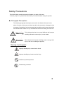
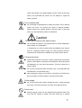
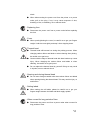
LM400e Series
SATO ASIA PACIFIC PTE. LTD.
438A ALEXANDRA ROAD
#05-01/04 ALEXANDRA TECHNOPARK
SINGAPORE 119967
Tel: (65) 6271 5300
Fax: (65) 6273 6011
Sales Hotline: (65) 6276 2722
Service Hotline: (65) 6273 6455
Email: [email protected]
Website: www.satoworldwide.com
Be sure to ask your dealer about our maintenance contracts
to ensure peace of mind during your usage of SATO products
© Copyright 1994 – 2006
SATO International
Warning: This equipment complies with
a Class A computing device. Operation
cause
unacceptable interference to radio and
whatever steps are necessary to correct
the requirements in Part 15 of FCC rules for
of this equipment in a residential area may
TV reception requiring the operator to take
the interference.
All rights reserved. No part of this document may be reproduced or issued to third
parties in any form whatsoever without the express permission of SATO. The
materials in this document are provided for general information and are subject to
change without notice. SATO assumes no responsibilities for any errors that may
appear.
Version: SI-LM4xxe-01rA-16-01-OM
Features of LM400e Series
The LM400e Series – the rugged industrial generation of high performance
printers with high resolution capabilities. The LM400e is a user-friendly printer
providing high throughput and print speed in barcode label production.
Superior print performance
The LM400e ensures high print quality, enlarges and prints various types of
fonts in a free layout.
Operation panel and LCD display
The LM400e is user-friendly and operable using two keys on the operation
panel. The instruction messages to be displayed on the LCD screen will show
you how to use this printer.
Durability and easy handling
The LM400e Series printers feature a heavy-duty print mechanism for barcode
label production in large quantity and ensure great durability.
An easy care and cleaning step are provided for daily use.
Ⅰ
Safety Precautions
This Quick Guide contains important information for safety of the user.
To insure proper use, please read these Safety Precautions before using this product.
▲ Pictograph Descriptions
The following pictograph descriptions are used in this Quick Guide and on the
printer for safety of the user and others as well as the prevention of damage or loss
to property. Descriptions for the pictographs and symbols used in these instructions
are included below. Make sure you understand them before reading the main text.
Warning
Caution
This indicates that there is a strong likelihood that improper
handling will lead to serious injury or even death.
This indicates that improper handling poses a strong risk of
injury to the user or damage to property.
Meaning of pictographs
: Improper handling may cause electric shock.
: Improper handling may lead to serious injury.
: Prohibited (restricted) actions.
: Disassembly prohibited.
Ⅱ
: Do not dispose the printer by fire, or expose it to heat, or put in fire.
: Unplug the printer from power outlet.
: Connect ground wire to ground slot.
Warning
: Place the printer on a surface that is flat and level
●
Do not leave the printer on unstable surfaces. If the printer falls and
hits someone, it could cause injury.
: Do not expose the printer to liquids or moisture
●
Do not place objects filled with liquids, such as beverages, vases,
or chemical product near the printer. Also, do not place small metal
objects near the printer. If the liquids have been spilled or objects
have fallen into the printer, turn off the power immediately,
disconnect the power cord from the power outlet, and contact your
nearest dealer, service center or the store where you purchased
the printer. Continue use of the printer in this condition may cause
fire or electric shock.
: Do not insert foreign material into the printer
●
Do not insert or drop any metal objects or flammable objects into
the openings (cable end, socket for interface connection). If the
foreign material has fallen into the printer, turn off the power
immediately, disconnect the power cord from the power outlet, and
contact your nearest dealer or service center or the store where
you purchased the printer. Continue use of the printer in this
condition may cause fire or electric shock.
Ⅲ
: Use only the designated electrical power and voltage
●
Use the type of power source indicated on the printer. Different
voltage may cause fire or electric shock.
: Connect ground wire
●
Make sure to connect the ground wire of the printer to the ground
slot. Failure to do so may cause electric shock.
Warning
: Power cord
●
Do not attempt to damage, break, or modify the power cord. Also,
avoid placing a heavy object on, heating, or pulling the power cord.
This may damage the power cord causing fire and electric shock.
●
If the power cord becomes damaged in any way (exposed cable
core, breaking of wire), contact your nearest dealer, service center
or the store where you purchased the printer. Continue use of
damaged power cord may cause fire or electric shock.
●
Do not attempt to modify, jerk, knot, sharply bend, or otherwise
abuse the power cord. Continue use of damaged power cord may
cause fire or electric shock.
: In case of drop or damage
●
If the printer was dropped or damaged, turn off the power
immediately, disconnect the power cord from the power outlet, and
contact your nearest dealer, service center or the store where you
purchased the printer. Continue use of the printer in this condition
may cause fire or electric shock.
: Do not use the printer in abnormal condition
●
In the case of abnormalities such as smoke or foul odors from the
printer, stop using the printer immediately. Continue use of the
printer in this condition may cause fire or electric shock. Turn off
the power immediately, disconnect the power cord from the power
Ⅳ
outlet, and contact your nearest dealer, service center or the store
where you purchased the printer. Do not attempt to repair the
printer yourself.
: Do not disassemble
●
Do not attempt to disassemble or modify the printer. Fire or electric
shock may occur. For service and repair of internal problem,
please contact your nearest dealer or service center or the store
where you purchased the printer for assistance.
Caution
: Do not use in locations with high humidity
●
Do not place the printer in any places where it will be subjected to
high humidity or condensation.
If condensing, turn off the power switch immediately, stop using it
and dry completely without using any heat producing devices.
Continued use under these conditions may cause electric shock.
: Carrying the printer
●
Disconnect the power cord from a power outlet before moving the
printer to other places. Leaving it connected and moving the printer
will damage to the cord and connections. This may cause fire or
electric shock.
●
Do not carry the printer when the label is set. If the label falls and
hits someone, it could cause injury.
●
When placing the printer on the floor or the table, be careful not to
get your fingers or hands caught in the legs of the printer.
: Power supply
●
Do not touch the power switch, replace the fuse, or plug-in/unplug
the power cord with wet hands. This may cause electric shock.
: Power cord
●
Keep the power cord out of any appliances that produce heat. This
may melt the coating of power cord and cause fire or electric
Ⅴ
shock.
●
When disconnecting the power cord from the printer or a power
outlet, pull on the plug. If not, it may cause exposure of wire,
breaking of wire, overheating, fire or electric shock.
: Replacing fuse
●
Disconnect the power cord from a power outlet before replacing
the fuse.
: Cover
●
When opening/closing the cover, be careful not to get your fingers
caught. Hold the cover tightly and stop it from dropping down.
: Thermal head
●
Thermal head will become hot during the printing process. When
changing carbon ribbon and labels or when cleaning after printing,
be careful not to get burnt.
●
Contact with the edge of thermal head with bare hands may cause
injury. When changing the carbon ribbon and labels or when
cleaning, be careful not to get injured.
●
Do not replace the thermal head by yourself. Doing so may result
in injuries, burns or electric shock.
: Opening and closing thermal head
●
Do not insert foreign material other than carbon ribbon and labels
when opening/closing the thermal head. This may result in injury or
malfunction.
: Setting labels
●
When setting the roll labels, please be careful not to get your
fingers caught between the label and label supply spindle.
: When unused for long periods of time
●
Disconnect the power cord from a power outlet when unused for
long periods of time.
Ⅵ
: Maintenance and cleaning
●
Disconnect the power cord from a power outlet when maintaining
or cleaning the printer.
Ⅶ
Table of Contents
●
●
●
●
●
●
●
●
●
●
Precautions for installation and handling……………………………..1, 2, 3
Unpacking……………………………………………………………………...4
Accessories…………………………………………………………………….5
Names of parts…………………………………………………………..6, 7, 8
Setting roll label……………………………………………………….9, 10, 11
Setting fan-fold label………………………………………………..12, 13, 14
Setting carbon ribbon……………………………………………….15, 16, 17
Adjusting pitch sensor……………………………………………………….18
Turning on power………………………………………………………..19, 20
LM400e Series specifications………………………………………………21
Precautions for installation and handling
Printer operation can be affected by the printer environment.
Refer to the following instructions for installation and handling of LM400e.
▲ Select a safe location
When selecting a location for installation of LM400e, consider the following topics.
Place the printer on a surface that is flat and level
If the surface is not flat and level, this may result
in poor print quality. This may also cause
malfunction and shorten the life span
of the printer.
Do not place the printer on a location that produces vibration
Do not carry the printer when the roll label is set.
Giving serious vibration or shock to the printer
may cause malfunction and shorten the life span
of the printer.
Keep the printer out of high temperature and humidity
Avoid locations subject to extreme or rapid
changes in temperature or humidity.
Exposure to these conditions may cause
Electrical problems within the printer.
1
Avoid dust
Dust buildup may result in poor print quality.
This may cause not only malfunction but
also shorten the life span of the printer.
Keep out of direct sunlight
This printer has a built-in optical sensor.
Exposure to direct sunlight will make the
sensor less responsive and may cause
the label to be sensed incorrectly.
Close the cover when printing.
Do not place the printer near crane or pressing machine.
Machineries such as crane and pressing
machine require large amount of power.
This may cause electrical noise or voltage
reduction.
Avoid such locations to reduce the risk of
malfunction or damage to the printer.
2
▲ Power supply
The LM400e Series require AC110-220V.
Provide a stable source of electricity to the printer
Do not share the power outlets with other
appliances such as a heater and refrigerator
requiring a measurable amount of power.
Also, avoid using the power outlet near such
appliances are plugged into.
This may cause voltage reduction and malfunction.
Connect the power cord to a grounded
power outlet
Make sure to have the facility equipped with
the ground slot.
3
Unpacking
Taking the LM400e from the box and removing the protective molded cover
and plastic cover, it is ready for installation.
Protective molded cover (top)
Printer
Protective molded cover (bottom)
Accessory 1
Accessory 2
Box
4
Accessories
Make sure you have received all of the following items in this package.
If there are any accessories missing, contact your nearest dealer or the store where you
purchased the printer.
Power cord
Power cord
Quick Guide
▲ Box
Keep the box and cushioning material that protects the printer (2 pc. each for top and
bottom).
When sending your printer for service, reuse the box and cushioning material.
5
Names of parts
Side cover
Ribbon take-up spindle
Ribbon supply spindle
Operation panel:
LCD for displaying messages,
two operation keys, two-color
LED for indicating printer
status
Power ON/OFF switch:
Turns power ON or OFF.
“I” is ON.
“O” is OFF.
Label
supply spindle
Interface board:
Changes the interface
using an optional
interface board
AC Input connector:
Connect the power cord and apply
the current to the printer.
Fuse cover:
Fuse is placed inside.
6
Label stopper
Secures the roll label
Thermal head (consumable part)
Prints data on the media
Platen roller (consumable part)
Discharges the printed media
Head lock lever
Fuse
When the current exceeding
particular level runs
through the printer, a fuse
will be broken to protect the
printer.
7
▲ Operation Panel
Instructions and error messages are displayed in alphanumeric.
Display panel
Displays an error message and
instructions, etc.
LINE key
Toggles the printer between on-line and
off-line mode for print start/stop and for
transmitting/receiving data.
FEED key
Feeds the label.
Press once to feed one blank label.
*When turning the power ON, or when the label is
not at the right position after setting the label,
press the FEED key to adjust the label position.
DIP switch
STATUS
Sets the operational parameters of printer
Indicates the printer status.
Green: Enabled for print and data communication
Red: An error occurred.
Off: Disabled for print and data communication
Adjustments
Can be used for adjustment when servicing.
Do not use this volume unless otherwise instructed.
PRINT : Adjusting print darkness
OFFSET: Adjusting tear-off position
PITCH : Adjusting home position of the label
8
Setting roll label
1
Side cover
Open the side cover.
2
Push up the purple head lock lever
in the direction of an arrow to open
the thermal head.
Head lock
lever
Thermal head
3
Turn the slide guide in the direction of an arrow and leave the guide on the angle.
Slide guide
9
4
Place the roll label on the label
supply spindle.
Roll label
Slide the label stopper and
Label stopper
adjust to the label width.
Label supply
spindle
5
Thread the label under the label
guide and pitch sensor.
Make sure that the side of label
touches the guide roller slightly.
Caution
Label
*Thermal head and the
Label guide
surrounding areas will become
hot during the printing process.
Pitch sensor
When changing the label
after printing, be careful not to
get burnt.
*Contacting the edge of thermal
head with bare hands may
result in injury.
When changing the labels, be
careful not to get injured.
Guide roller
Label guide
10
6
Turn the slide guide to vertical position and adjust the guide to touch the label front
end slightly.
Slide guide
7
Push down the purple head lock lever in
the direction of an arrow to close
the thermal head.
Head lock lever
8
Close the side cover.
Caution
When closing the cover, be
careful not to get your fingers
caught in the cover.
11
Setting fan-fold label
1
Open the side cover.
Side cover
Push the nylon rivet from the inside
of the printer and remove the cover
for fan-fold opening.
2
Push up the purple head lock lever in
the direction of an arrow to open
the thermal head.
Head lock
lever
Thermal head
3
Turn the slide guide in the direction of an arrow and leave the guide on the angle.
Slide guide
12
4
Put the label through the fan-fold
Label stopper
opening.
Slide and adjust the label stopper
to touch the side of label slightly.
Fan-fold label
5
Thread the label under the label
guide and pitch sensor.
Make sure that the side of label
touches the guide roller slightly.
Caution
*Thermal head and the
surrounding areas will become
hot during the printing process.
When changing the label after
Pitch sensor
printing, be careful not to get
burnt.
*Contacting the edge of thermal
head with bare hands may
result in injury.
When changing the labels, be
careful not to get injured.
Guide roller
Label guide
13
6
Turn the slide guide to vertical position and adjust the guide to touch the label front
end slightly.
Slide guide
7
Push down the purple head lock
lever in the direction of an arrow
to close the thermal head.
Head lock lever
8
Close the side cover.
Caution
When closing the cover, be
careful not to get your fingers
caught in the cover.
14
Setting carbon ribbon
Use only SATO carbon ribbons.
Use of other than approved carbon ribbons may result in unsatisfactory print quality and/or
damage to the print head and may void your warranty.
1
Side cover
Open the side cover.
2
Push up the purple head lock lever in
the direction of an arrow to open the
thermal head.
Head lock
lever
Thermal head
3
Place the carbon ribbon on
the ribbon supply spindle and
Ribbon
supply spindle
push the ribbon roll all the way
to the inside of the printer.
(Confirm winding direction)
Carbon ribbon
15
4
Place an empty ribbon core on the
ribbon take-up spindle.
Ribbon core
5
From the ribbon supply spindle,
thread the carbon ribbon under
the thermal head and to the
ribbon take-up spindle.
Ribbon
take-up
spindle
Tape the free end of carbon
ribbon to the ribbon core, and
Tape
wind a few times in the direction
of an arrow.
Be sure to confirm that the carbon
ribbon is set as shown in the picture
on the right.
Caution
*Thermal head and the surrounding
areas will become hot during the
printing process.
When changing the labels after
printing, be careful not to get burnt.
*Contacting the edge of thermal head
with bare hands may result in injury.
When changing the labels, be
careful not to get injured.
16
6
Push down the purple head lock lever
in the direction of an arrow to
close the head.
Head lock lever
7
Close the side cover.
Caution
When closing the cover, be
careful not to get your fingers
caught in the cover.
17
Adjusting Pitch Sensor
1
Side cover
Open the side cover.
2
To adjust the pitch sensor position,
Slide the green pitch sensor knob
Pitch sensor
at the far end of the slide guide.
It is located at the backmost (on the
sensor frame side).
Pitch sensor knob
3
Close the side cover.
Caution
When closing the cover, please
be careful not to get your fingers
caught in the cover.
18
Turning on Power
Connect the power cord and turn on the printer.
Power supply
After installing the printer, connect the power cord as instructed below.
▲ Power cord and power outlet
As shown in this picture, included power
cord has three contacts.
The socket has three contacts; the third one
is connected to a ground for safety.
If your power outlet has three slots,
plug in the power cord as it is.
To connect the power cord to the printer,
be sure to confirm the top/bottom of plug.
When connecting the power cord, use the
other hand to secure the printer.
Connect the power cord into the printer first, and then plug the other end into the
power outlet.
Printer
Power outlet
Power cord
19
If your power outlet has two slots, use a 3- to 2-prong adapter.
Warning
Power outlet
Connect the earth lead to the
ground slot.
Failure to do so may cause
electric shock.
Power cord
2-prong plug
adapter
Earth lead
Ground slot
Turning the power ON
Press the power switch to the direction of [I].
When the printer is turned on, a [ONLINE] message will be displayed on the LCD panel.
Caution
Do not operate the power switch or plug-in/unplug the power cord with wet hands.
This may cause electric shock.
20
LM400e Series specifications
Model:
LM408e / LM412e
Print method:
Thermal transfer / Direct thermal
Print resolution:
203/305dpi
8 dots mm/12 dots mm
Media size:
Max. 128mm
Width (including backing liner 131mm)
Printable area:
Max. 104mm width / Max. pitch 178mm
Max. print speed:
6 inch/s (approximately 150mm/sec)
Dimensions:
W271 x D430 x H321mm (Standard)
13kg (Standard)
Roll media:
Max. external diameter 8 inch (150m/roll)
Face in, 3 inch roll
Fan-fold:
Max. folded height 100mm, Feeding the fan-fold externally
Sensor type:
Toggles sensor between Reflective sensor/Transmissive sensor,
Carbon ribbon:
450m/roll
Note) Carbon ribbon width needs to be wider than media width.
Power:
110-220VAC±10%
50/60Hz±1%
Environment:
Operating
5 to 40 degrees C
Storage
-20 to 40 degrees C
Humidity
30 to 85% Non-condensing
21