1
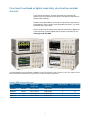
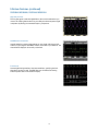
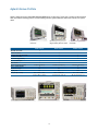
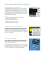
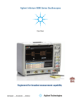
Agilent
Infiniium 8000 Series Oscilloscopes
Superior mixed-signal analysis and debug
Data Sheet
If you haven’t purchased an Agilent scope lately, why should you consider
one now?
If you’re like most engineers, you never know what your next project will
demand from you. You need an oscilloscope that can adapt to a wide variety of
debug and test challenges.
We built in the powerful features you’d expect in any Infiniium scope. Then we
engineered the scope for superior mixed-signal debug and analysis, so it would
be a flexible tool in your arsenal.
There is no better way to experience the superiority of the Infiniium 8000 Series
scopes than to see it. Contact Agilent today to request an evaluation. Or visit:
www.agilent.com/find/8000
The Infiniium 8000 Series offers bandwidths of 600 MHz and 1 GHz. Equipped with an XGA LCD display, scopes can be ordered as either
a DSO or MSO. With built-in GPIB and low 5U high profile, it's ideal for rackmount applications.
Infiniium 8000 Series oscilloscopes
Model
Bandwidth
Sample rate
4-ch/2-ch
Standard memory
4-ch/2-ch
Scope channel
Logic channel
DSO8064A
600 MHz
2 GSa/s/4 GSa/s
4 Mpts/8 Mpts
4
–
MSO8064A
600 HHz
2 GSa/s/4 GSa/s
4 Mpts/8 Mpts
4
16
DSO8104A
1 GHz
2 GSa/s/4 GSa/s
4 Mpts/8 Mpts
4
–
MSO8104A
1 GHz
2 GSa/s/4 GSa/s
4 Mpts/8 Mpts
4
16
2
What makes the Infiniium 8000 Series flexible enough for a whole range of
test and debug challenges?
Great measurement capability
Oscilloscope:
The powerful features of our Infiniium Series oscilloscopes, coupled with good
scope specifications give you excellent signal representation on both DSO and
MSO models.
Logic analyzer:
16 digital channels let you see critical data values and timing relationships on
MSO models.
Wide range of debug and compliance application software
Need accurate answers to your measurement questions?
The Infiniium 8000 Series offers a wide range of application-specific software for
debug, analysis and compliance testing. Which application is right for you? Take
a look at the possibilities on pages 15 to 19.
Sized to fit your environment
Need to stack other instruments on top? Need to rackmount your scope?
The Infiniium 8000 Series retains a traditional form factor with just a 5U high
hight.
3
Oscilloscope Capabilities
Scope channels ensure superior viewing of signals under test. All models incorporate a powerful,
feature-packed Infiniium oscilloscope with responsive deep memory.
Up to 1 GHz bandwidth and 4 GSa/s high
sample rates guarantee you’ll see a good
representation of the analog
characteristics of signals you’re testing
Mask tests, histograms and a wide variety
of functions provide deep signal analysis.
4
Oscilloscope Capabilities (continued)
Responsive deep memory
With standard 4 Mpts, and up to 128 Mpts of memory, you can capture long
time periods while retaining fast sample rates. Fast update rates mean your
scope stays responsive with deep memory on, ensuring precise representation of
analog signals.
Advanced triggering
Advanced triggers are essential when you are investigating suspected problems.
Infiniium offers a full range of advanced triggers to help you isolate and capture
the condition you need to characterize.
Drag and drop measurements
It’s simple: drag an icon from the measurement bar and drop it on the cycle you
want to measure. You can make up to five measurements on your waveforms, on
up to five different cycles. All of the measurements appear at the bottom of the
display with statistics and are color-coded to the channel you are measuring.
5
MSO Capabilities
MSO models add 16 high-speed timing channels
Use the timing channels to evaluate control signal relationships
and data buses up to 16 bits wide. Use symbols to more quickly
interpret waveforms.
Designing with Altera or Xilinx FPGAs? Use the FPGA dynamic
probe for rapid internal FPGA measurements. Using I²C, SPI,
or CAN? Use the digital channels to acquire and decode these
buses, preserving analog channels for other time-correlated
measurements.
Digital and mixed-signal trigger
Trigger on and display individual signals or buses. With precise time-correlation
between analog and digital signals, confidently trigger across any combination of
analog and digital signals simultaneously.
Industry’s only segmented memory for both analog and digital channels
Capture short bursts without consuming memory during periods when the trigger condition is not met. Agilent is the only vendor that supports segmented memory capture
on both analog and digital channels.
Waveform and Listing Windows
View buses as waveforms or easily follow events in the listing window expandable
to the entire display. A blue tracking marker provides time-correlation between waveform and listing displays.
6
Infiniium Features
DSO8064A/MSO8064A, DSO8104A/MSO8104A
Serial, parallel and wideband
signal decode
Whether you are working on serial,
parallel or wideband signals, you can
use the 8000 Series to decode your
waveforms. When you are working on
parallel waveforms, you can even customize the bus states to be displayed
on the decode table.
Chart mode feature
Chart mode applies trend analysis techniques to see how the digital output
(ADC, counter, address lines, etc.) vary over time. This method is effective to
quickly find anomalies of the digital signals. You can also apply math operators
such as “FFT” to view the frequency domain of the analog values.
Powerful frequency and modulation analysis
The 8000 Series provides superior frequency domain analysis, RF-signal
demodulation and extensive standard-specific analysis coverage including
WiMAX™, WLAN, 3GPP, RFID and UWB with the optional 89601A Series VSA
software. With digital and wireless applications merging, you can use the 8000
Series one-box solution to validate the time and frequency domains.
Extensive application software suite
The 8000 Series provides wide application coverage for you to quickly and easily
verify your designs. Application packages include jitter, DDR, USB, Ethernet,
FlexRay, CAN, SPI, I2C, and FPGA.
7
Infiniium Features (continued)
DSO8064A/MSO8064A, DSO8104A/MSO8104A
Simple zooming
Zooming with Infiniium’s graphical user interface is simple and convenient. Just
use the mouse to draw a box around the area of interest and click inside. Zoom
uses the full display so you get meaningful vertical as well as horizontal resolution gains. Use multiple zoom boxes to see deep inside your signal. Zooming
couldn’t be simpler or faster.
Bus mode display
Bus mode display on MSOs allows quick and easy read-out of hexadecimal
representation of logic signals. Bus state mode display allows the bus readout
to be updated only upon the edge of the clock source you select. Available only
with Infiniium MSO models.
Dialog boxes for easy setup
With Infiniium, you don’t need to navigate through annoying softkey menus.
Dialog boxes display all the choices you need for measurement setups, all in
one place. Help is available for each field, guiding you through each step.
E-mail on trigger
Infiniium can automatically send an e-mail with a screen image of the display
when the scope triggers. You can have your Infiniium send an e-mail to you or
a message to your cell phone then control your scope from any Java™-enabled
Web browser with Infiniium’s Web-enabled feature.
8
Infiniium Features (continued)
DSO8064A/MSO8064A, DSO8104A/MSO8104A
Web-enabled control
For distributed teams, simply set up Infiniium on your LAN, and up to three
users can access it from any Java-enabled Web browser. No special software is
required. You can easily grab screen shots for a report, or troubleshoot designs
from a remote location.
AutoMask and mask test
Mask testing is simplified with AutoMask. Acquire a waveform, define tolerance
limits, and create a test envelope. Mask testing provides a pass/fail comparison
of an incoming signal to the test envelope. Easily test your design’s conformance to industry standards with the communication mask test kit option.
Advanced triggering
Advanced triggers are essential when you are investigating known problems.
Infiniium offers a full range of advanced triggers to help you isolate and capture
the condition you need to characterize. Advanced trigger setups are simplified
by using intuitive dialog boxes with descriptive graphics.
Color-graded persistence with histograms
By providing seven levels of color grades for a visual representation of waveform distribution, color-graded persistence makes it easy to pick out signal
anomalies and see how often they occur. Histograms quantify both noise and
jitter in your target system.
9
Infiniium Features (continued)
DSO8064A/MSO8064A, DSO8104A/MSO8104A
High/low pass filter
This function applies a real-time digital filter to the source waveform that you
choose. This filtering feature enhances your ability to examine important signal
components by filtering out unwanted frequency components.
QuickMeasure and statistics
Instantly make five common measurements on your signal, with easy-to-read
statistics, by pressing the QuickMeas+ button on the front of your Infiniium. The
measurements displayed can be easily customized.
Pseudo state
Convert digital timing waveforms into state waveforms, specifying the clock
edge when your data is valid. The MSO filters out all invalid states leaving
exclusively valid states in the waveform display.
10
Connectivity and Probing
Connectivity
Industry compatibility
Export screen shots and waveforms in numerous industry-standard formats. In addition, the 8000 Series supports compatibility with the following
• IVI COM driver for application development environments such as Visual
Studio, Agilent VEE, NI LabView and MATLAB instrument control toolbox.
www.agilent.com/find/adn
• IntuiLink tool bars and data capture.www.agilent.com/find/intuilink
• LXI Class C including built-in Web control
Probing
The Infiniium 8000 Series oscilloscopes ship with four 10073C 10:1 divider passive
probes per scopeand probe accessory pouch.
With both 50 Ω and 1 MΩ inputs, Infiniium 8000 Series scopes support a wide range
of probes, including Agilent’s InfiniiMax Series probes.
Agilent offers an innovative family of probes that are engineered for signal access
and measurement accuracy. Whether you’re looking for simple passive probes, the
high bandwidth and low loading of an active probe, or specialty probes for current
or high voltage, we can meet your needs. Our innovative accessories allow reliable
connection to challenging components like small pitch devices, surface mount ICs,
and DDR BGA packages – even hands free! To see our entire award-winning portfolio
of passive, single-ended active, differential active, and current probes as well as an
oscilloscope compatibility chart, please view the Agilent Probes and Accessories
Selection Guide. publication number 5989-6162EN.
11
View Scope logic analyzer and
oscilloscope correlation
Use simple time-correlated measurements between your scope and Agilent
16900, 16800, 1680, or 1690 Series
logic analyzer at no charge. Scope and
logic waveforms are integrated into a
single logic analyzer display for easy
viewing analysis – all with a simple
point-to-point LAN connection. You
can also cross trigger the instruments,
automatically de-skew the waveforms
and maintain marker tracking between
the instruments.
Drag-and-drop measurements from the
measurement bar provide an intuitive way
to make a measurement on a particular
cycle of your waveform.
Up to 128 Mpts of MegaZoom fast deep
memory sustains maximum sample rates
for long time captures.
Remote access via Web browser or
programming environment with GPIB
commands over LAN allows you to access
your oscilloscope from any networked PC.
Get fast answers to your questions with
the comprehensive built-in information
system. The task-oriented setup guide
provides step-by-step instructions for
several measurement procedures.
Touch screen display comes
standard for mouse-free
operation.
E-mail-on-trigger allows you to leave your
oscilloscope, and when that intermittent
event is captured, Infiniium sends you
an e-mail that tells you exactly when it
happened with an attached screen image.
10/100/1000 BaseT LAN interface lets
you easily print to network printers, save
files to network drives, and control the
oscilloscope remotely.
Label waveforms and add comments
to Infiniium’s display for thorough
documentation before saving
screen images.
Context-sensitive right-click menus allow
quick access to oscilloscope settings,
controls, and display properties.
High-definition XGA color display with
256 levels of intensity uncovers subtle
signal details that most oscilloscopes
won’t show you…enabled by nextgeneration MegaZoom technology.
Measurement markers can be easily
controlled via front-panel arrow keys
or dragging and dropping them with
the pointer.
12
QuickMeas+ key gives you any five
automated measurements with the push of
a button. You can also configure this key
to print/save screen images among other
functions.
MegaZoom technology enables you
to quickly pan and zoom through the
deepest waveforms for detailed analysis.
Award-winning ease-of-use is made
possible by attention to details like
Infiniium’s analog-like front panel controls,
color-coded to correspond to displayed
waveforms.
USB 2.0 port directly on front panel makes
it easy to save files to a USB mass storage
device.
Hands-free operation is available with
Infiniium’s VoiceControl option.
Open Windows XP Pro platform enables
you to install third-party applications
such as Excel, LabVIEW, and MATLAB to
perform custom analysis and processing,
all inside the oscilloscope.
XGA video monitor out provides the ability
to run third-party applications on a large
external display while the internal display
continues to display acquired waveforms.
AutoProbe interface completely
configures your oscilloscope and
provides power to various current and
active probes, including InfiniiMax active
probes.
Mixed signal oscilloscope (MSO)
models seamlessly integrate four analog
scope channels with 16 digital channels
that provide full-width viewing and
triggering across many embedded signal
interactions.
13
Agilent Infiniium Portfolio
Agilent’s Infiniium lineup includes 8000, 9000 and 90000A Series oscilloscopes. These share a number of advanced hardware and software technology blocks. Use the following selection guide to determine which best matches your specific
needs.
Lowest cost, ideal for
rackmount
600 MHz bandwidth
1 GHz bandwidth
2.5 GHz and 4 GHz bandwidth
> 4 GHz bandwidth
Bandwidth upgradability
50 Ω & 1 MΩ inputs
MSO models
Max 2-channel (4-channel)
Built-in GPIB available
Rackmount height
Display size
Footprint (H x W x D)
Widest range of applications.
Biggest display plus thin depth
8000 Series
9000 Series
√
√
√
√
√
√
√
20 GSa/s (10 GSa/s)
√
√
4 GSa/s (2 GSa/s)
√
5U
8”
8.5 “ x 17.2” x 17.3”
22 cm x 44 cm x 44 cm
8U
15”
12.9 “ x 16.8” x 9”
33 cm x 43 cm x 23 cm
14
Lowest noise, highest
bandwidth
90000 Series
√
√
√
40 GSa/s (40 GSa/s)
√
7U
12.1”
11.1 “ x 17” x 19.9”
28 cm x 43 cm x 51 cm
Infiniium Advanced Application Software
The Agilent 8000 Series Infiniium oscilloscope offers a broad portfolio of add-on applications that
enables you to customize your oscilloscope. These applications are available as add-on options at
your initial scope purchase or as user-installed options at a later time. For more information about
these options and to see if new applications have been added to our portfolio, please visit
www.agilent.com/find/8000scope-apps.
Xilinx and Altera FPGA dynamic probe for Infiniium MSO (N5397A and N5433A)
Agilent’s MSO FPGA dynamic probe provides rapid internal FPGA visibility
and quick instrument setup using an innovative core-assisted approach.
Measurement tasks that previously took hours can be done in a few mouse
clicks.
In a few seconds you can easily measure a different set of internal signals without changing your FPGA design. The FPGA dynamic probe also imports signal
names from your FPGA design to the MSO digital channel labels.
Low-speed serial data analysis software (Option 007 or N5391A)
The N5391A low-speed serial data analysis software provides a fast and easy
way to debug inter-integrated circuit (I2C) and 2-, 3- or 4-wire serial peripheral
interface (SPI) serial communication buses. The low-speed SDA software
provides the ability to capture and automatically display decoded serial data
in numerical format synchronized with the analog or digital waveform, display
decoded packets in a sortable listing window view with automatic click and
zoom capability, and perform search functions for a particular packet with
navigator controls.
Power measurement application (U1882A)
Agilent's power application provides a full suite of power measurements that
run directly on the Infiniium 8000 Series oscilloscope. The power measurement
application offers seven modules to help you characterize your devices (power
device analysis, input line analysis, output analysis, turn on/off analysis, transient analysis, modulation analysis and deskew analysis) in addition to report
generation. Make more accurate power supply efficiency measurements by using a U1880A deskew fixture to deskew your voltage and current probes.
15
Infiniium Advanced Application Software (continued)
Automotive serial data analysis software (Option 008 or N5402A)
The N5402A automotive serial data analysis software allows engineers to
view both protocol layer information and physical layer signal characteristics for
CAN and FlexRay buses inside a single instrument, the Infiniium oscilloscope.
Numerical decode values are automatically displayed and synchronized below
the captured signal’s waveform. They can also be viewed in a sortable listing
window which allows automatic click and zoom capability to the signal of interest as well as performs search functions for a particular packet. The option also
provides software clock recovery and real-time eye diagram measurements.
InfiniiScan event identification software (Option 009 or N5415A)
The Agilent InfiniiScan event identification software quickly and easily identifies
signal integrity issues. This innovative software scans through thousands of
acquired waveforms per second to help isolate anomalous signal behavior.
InfiniiScan can scan for multiple events simultaneously with resolution down to
70-ps events plus automated navigation to failure events. InfiniiScan software
finders consist of: measurement, zone qualify, generic serial, non-monotonic
edge and runt. InfiniiScan goes beyond the classic limitations of hardware triggering and deep memory.
High-speed serial data analysis software (Option 003 or N5384A)
The N5384A high-speed serial data analysis (SDA) software provides an effective way to validate signal integrity for designs employing high-speed serial
interfaces with embedded clocks. The high-speed SDA software, when used
with Infiniium oscilloscopes, allows you to:
• Recover embedded clocks with first-order PLL, second-order PLL, or constant
frequency algorithms
• Choose an external reference clock input
• Display the recovered clock synchronized with the analog waveform view of
the serial data stream
• Build real-time eye diagrams
• Unfold real-time eye diagrams to easily locate failures versus time
• Perform custom mask testing
• Make TIE jitter measurements relative to the recovered clock or external
reference clock
16
Infiniium Advanced Application Software (continued)
EZJIT jitter analysis software (Option 002 or E2681A)
The E2681A jitter analysis option provides the most commonly needed jitter
measurements, including cycle-cycle jitter, N-cycle jitter, period jitter, time interval error, setup and hold time, measurement histograms, measurement trending
and jitter spectrum. EZJIT provides a setup wizard that guides you through the
setup of the jitter measurement, explains how each jitter measurement works,
and tells you when to use it.
N5392A Ethernet electrical performance validation and compliance software
The Agilent N5392A Ethernet electrical performance validation and compliance
software performs a wide range of electrical tests to meet the Ethernet electrical
specifications for 1000Base-T, 100Base-TX and 10Base-T systems as documented in the IEEE 802.3-2005 and ANSIX3.263-1995 standards.
Features:
• Test setup wizard guides you through test selection, configuration, connection, execution and results reporting
• Fixtures available: N5395B or N5395C or N5395C Ethernet test fixtures and
N5396A jitter test cable
• Supports 1000Base-T disturbing signal measurements with the use of 33250A
arbitrary waveform generators
• Supports return loss measurements with most HP/Agilent vector network
analyzers
17
Infiniium Advanced Application Software (continued)
USB 2.0 performance validation and compliance software (N5416A)
The Infiniium USB 2.0 electrical performance validation and compliance option
provides a fast and reliable way to verify USB electrical specification compliance
for USB 2.0 devices, hosts, and hubs. The Infiniium USB 2.0 test option executes
the official USB-IF MATLAB scripts with MATLAB’s runtime engine embedded
in the oscilloscope. Results are displayed in a flexible report format with margin
analysis. The Infiniium 8000 Series with bandwidths of 600‑MHz and 1 GHz can
appropriately test USB 2.0 low- and full-speed buses. The E2646A SQiDD test
fixture is available for making the physical connection between the Infiniium
oscilloscope and the device under test.
DDR1 compliance test application (U7233A)
The Agilent U7231A DDR1 compliance test application provides you with a fast
and easy way to characterize and evaluate the electrical and timing parameters
of your DDR1 design. The tests performed by U7231A are based on the JEDEC
JESD79E DDR SDRAM Specification.
Features:
• Setup wizard for quick setup and testing
• Automated measurement and analysis to save you time and effort
• Margin analysis to indicate how close your device comes to passing or failing
the test
• Automatic HTML report generation for easy documentation
Vector signal analysis software for Infiniium (89601A)
The 89601A vector signal analyzer (VSA) software, used with the Infiniium 8000
Series, enables flexible signal analysis and demodulation up to 1‑GHz bandwidth
for troubleshooting wideband modulated signals in radar and communications
applications. The solution provides:
• Flexible demodulation for measuring constellation diagrams, carrier offset,
and frequency error for QPSK signals, 256‑QAM signals and much more
• Display formats including spectrogram, phase vs. time, and frequency vs. time
for rapid insight into complex signal behavior
• Error vector magnitude measurements (with 89601A Option AYA)
• Markers to facilitate frequency, amplitude, offset, power, phase, other measurements
• Time gating that allows you to select specific portion of signals for signal
analysis
• Variable frequency resolution
18
Infiniium Advanced Application Software (continued)
Infiniium user-defined function (Option 010 or N5430A)
The Agilent N5430A Infiniium user-defined function opens up new possibilities for mathematical analysis features of Infiniium by creating a gateway to
MATLAB from MathWorks (www.mathworks.com/). You can now add your
favorite MATLAB .m scripts as “math function operators,” and use them just
like any other standard functions provided with the Infiniium. The scope passes
data to MATLAB and then displays the result back on the screen in real time.
Requires MATLAB software separately.
Features:
• Seamless gateway to powerful MATLAB analysis functionality
• Real-time analysis, real-time update
• Requires XML programming and .m script file
• Supports 2 control variables, and 2 sources
• Supports MATLAB version R14 SP1 and later
My Infiniium integration package (Option 006 or E2699A)
The E2699A My Infiniium integration package option allows you to extend the
power of your Infiniium oscilloscope by letting you launch your application
directly from the oscilloscope’s front panel or graphical user interface. Any
program that can be run under Windows XP can be launched from the Infiniium
scope user interface or front panel, including applications such as Agilent VEE,
Microsoft Excel, or MATLAB.
Communication mask test kit (E2625A)
Take the frustration out of communications testing and prove your designs
conform to industry standards with the communication mask test kit option.
Infiniium’s familiar Windows interface makes it easy for you to access the
masks you need and configure your tests.
In addition, the communication mask test kit comes with a set of electrical communication adapters to ensure convenient, reliable, and accurate connections to
your device under test. Includes more than 20 industry-standard ANSI T1.102,
ITU-T G.703, and IEEE 802.3 communication signal mask templates.
19
Infiniium Active Probing
Probing importance
If you are concerned about accurate reproduction of your signals as they
appear on your device under test, you need the best end-to-end measurement
system starting at the probe tip. To ensure that you achieve the full bandwidth
of your oscilloscope, you need to ensure you are using a probe that shows
you the details of the signal. For example, the 1 GHz models (DSO8104A and
MSO8104A) will need an active probe with the bandwidth of at least 1 GHz. The
1156A or the 1130A active probes are recommended to achieve the full system
bandwidth of your scope. In addition, a selection of probes that specifically
enhances or utilizes Infiniium 8000 Series are also listed.
For more complete information on Agilent probing solutions please see the
Oscilloscope Probes and Accessories Selection Guide (Agilent publication
number 5989-6162EN).
Recommended probes
Model
Probe bandwidth
System bandwidth
1156A
1.5 GHz active probe
1130A
1.5 GHz InfiniiMax probe amplifier (No probe heads included 1)
Other probe choices
Model
Description
10070C
1165A
1147B
N2780A
N2781A
N2782A
N2783A
1153A
E5396A
N5450A
1 GHz with MSO8104A and DSO8104A
600 MHz with MSO8064A and DSO8064A
1 GHz with MSO8104A and DSO8104A
600 MHz with MSO8064A and DSO8064
1:1, 1 MΩ passive probe 2
10:1, 10 MΩ 600-MHz passive probe
50 MHz, 15 A AC/DC current probe
2 MHz/500 A AC/DC current probe 3
10 MHz/150 A AC/DC current probe 3
50 MHz/30 A AC/DC current probe 3
100 MHz/30 A AC/DC current probe 3
200 MHz differential probe
Half-size (17 channel) soft touch connectorless logic probe for MSO models
InfiniiMax extreme temperature extension cable for temperature chamber testing
1. For a complete probing solution, also order a connectivity kit or individual probe head(s) (E2675A, E2668A, E2669A).
2. Fine-pitch and IC probing kits available (10072, 10075A).
3. Order N2779A 3-channel power supply for N2780A series current probe.
20
Infiniium Performance Characteristics
Vertical: scope channels
Input channels
Analog bandwidth at 50 Ω (–3 dB) 1
Calculated rise time 2 at 50 Ω
Input impedance 1
Sensitivity 3
Input coupling
Hardware bandwidth limit
Vertical resolution 4
Channel-to-channel isolation
(any two channels with equal V/div
settings)
DC gain accuracy 1, 3, 5
Maximum input voltage 1
1 MΩ
50 Ω
Offset range
1 MΩ
50 Ω
Offset accuracy 1, 3
Dynamic range
DC voltage measurement accuracy 1, 3, 5
Dual cursor
Single cursor
DSO8064A, MSO8064A, DSO8104A, MSO8104A
DSO8064A/DSO8104A: 4 analog
MSO8064A/MSO8104A: 4 analog + 16 digital
DSO8064A/MSO8064A: 600 MHz
DSO8104A/MSO8104A: 1 GHz
DSO8064A/MSO8064A: 583 ps
DSO8104A/MSO8104A: 350 ps
1 MΩ ± 1% (13 pF typical), 50 Ω ± 1.5%
1 mV/div to 5 V/div (1 MΩ)
1 mV/div to 1 V/div (50 Ω)
1 MΩ: AC, DC; 50 Ω: DC
20 MHz
8 bits, ≥12 bits with averaging
DC to 50 MHz: 50 dB
> 50 MHz to 500 MHz: 40 dB
> 500 MHz to 1 GHz: 30 dB
± 1.25% of full scale at full resolution channel scale
150 V RMS or DC, CAT I
± 250 V (DC + AC) in AC coupling
5 Vrms, CAT I
Vertical sensitivity
1 mV to < 10 mV/div
10 mV to < 20 mV/div
20 mV to < 100 mV/div
100 mV to < 1 V/div
1 V to 5 V/div
1 mV to < 5 mV/div
5 mV to < 200 mV/div
200 mV to 1 V/div
± (1.25% of channel offset +2% of full scale +1 mV)
± 8 div from center screen (1 MΩ)
± 12 div from center screen (50 Ω)
Available offset
±2V
±5V
± 10 V
± 20 V
± 100 V
±2V
±5V
± 20 V
± [(DC gain accuracy) + (resolution)]
± [(DC gain accuracy) + (offset accuracy) + (resolution/2)]
Example for single cursor accuracy for 70 mV signal, 10 mV/div, 0 offset:
Accuracy = ± [1.25% (80 mV) + (1.25% (0) + 2% (80 mV) + 1 mV ) + (0.4%/2) (80 mV)] =
± 3.8 mV
1. Denotes warranted specifications, all others are typical. Specifications are valid after a 30 minute warm-up period and ±10 °C from
firmware calibration temperature.
2. Rise time figures are calculated from t r = 0.35/bandwidth.
3. Magnification is used below 5 mV/div range. Below 5 mV/div, full scale is defined as 40 mV. Full scale is defined as the major
attenuator setting above an intermediate setting. (Major settings 50 Ω: 10 mV, 20 mV, 50 mV, 100 mV, 200 mV, 500 mV, 1 V, 1 MΩ: all
of the above plus 2 V).
4. Vertical resolution for 8 bits = 0.4% of full scale, for 12 bits = 0.024% of full scale.
5. The dc gain accuracy decreases 0.08% of full scale per degree C from the calibration temperature.
21
Infiniium Performance Characteristics (continued)
Vertical:
Analog noise floor
Volts/div
Full bandwidth
20 MHz hardware
bandwidth limit
5 mV
10 mV
20 mV
50 mV
100 mV
200 mV
500 mV
1V
5 mV
10 mV
20 mV
50 mV
100 mV
200 mV
500 mV
1V
Vertical: Digital channels
Number of channels
Threshold groupings
Threshold selections
User-defined threshold range
Maximum input voltage
Threshold accuracy
Input dynamic range
Minimum input voltage swing
Input impedance
Channel-to-channel skew
Glitch detect
Resolution 1 bit
DSO/MSO8064A
Vrms
50 Ω
Vrms
1 MΩ
341.9 µV
957 µV
1.61 mV
3.39 mV
9.59 mV
16.2 mV
210 μV
222 μV
365 μV
891 μV
1.47 mV
3.62 mV
8.92 mV
14.68 mV
351.8 µV
966.1 µV
1.64 mV
3.22 mV
9.87 mV
16.03 mV
219 μV
237 μV
371 μV
897 μV
1.48 mV
2.91 mV
8.19 mV
14.9 mV
204.8 µV 219.8 µV
228.3 µV 243.9 µV
Vp-p
50 Ω
1.61 mV
1.67 mV
2.44 mV
6.86 mV
11.56 mV
24.3 mV
69.1 mV
116.3 mV
1.53 mV
1.65 mV
2.67 mV
6.56 mV
10.65 mV
26.4 mV
65.7 mV
106.8 mV
MSO8064A, MSO8104A
DSO/MSO8104A
Vp-p
1 MΩ
Vrms 50 Ω
2.48 mV
6.91 mV
11.7 mV
22.9 mV
70.6 mV
114.6 mV
1.69 mV
1.72 mV
2.71 mV
6.66 mV
10.8 mV
21.0 mV
59.9 mV
108.2 mV
456.6 µV
1.26 mV
2.13 mV
4.47 mV
12.59 mV
21.39 mV
126.0 μV
206.0 μV
378.0 μV
1.084 mV
1.97 mV
3.75 mV
10.9 mV
19.8 mV
1.65 mV
1.75 mV
285.4 µV
315.5 µV
Vrms
1 MΩ
283.8 µV
312.7 µV
454.9 µV
1.25 mV
2.13 mV
4.19 mV
11.38 mV
21.1 mV
144.1 μV
212.1 μV
379.4 μV
1.08 mV
1.97 mV
3.93 mV
9.45 mV
19.06 mV
16 digital – labeled D15 to D0
Pod 1: D7 to D0
Pod 2: D15 to D8
TTL, 5.0V CMOS, 3.3V CMOS, 2.5V CMOS, ECL, PECL, user defined
± 8.00 V in 10 mV increments
± 40 V peak CAT I
± (100 mV + 3% of threshold setting)
± 10 V about threshold
500 mV peak-to-peak
100 kΩ ± 2% (~ 8 pF) at probe tip
2 ns typical, 3 ns maximum
≥ 2.5 ns
Resolution 1 bit
22
Vp-p
50 Ω
2.30 mV
2.41 mV
3.45 mV
9.51 mV
16.06 mV
33.85 mV
95 mV
160.9 mV
931 μV
1.55 mV
2.85 mV
8.18 mV
14.7 mV
28.2 mV
82.0 mV
149.5 mV
Vp-p
1 MΩ
2.22 mV
2.36 mV
3.42 mV
9.45 mV
16.13 mV
31.8 mV
86 mV
158.7 mV
1.06 mV
1.59 mV
2.85 mV
8.16 mV
14.7 mV
29.3 mV
70.8 mV
142.0 mV
Infiniium Performance Characteristics (continued)
Horizontal
Main time base range
Horizontal position range
Delayed sweep range
Resolution
Time scale accuracy 1
Delta-time measurement accuracy 1
DSO8064A, MSO8064A, DSO8104A, MSO8104A
DSO8064A/MSO8064A
DSO8104A/MSO8104A
≥ 256 averages, absolute (ps peak)
≥ 256 averages, standard deviation (ps rms)
No averaging, absolute (ps peak)
No averaging, standard deviation
Channel-to-channel deskew range
Modes
Reference positions
500 ps/div to 20 s/div
200 ps/div to 20 s/div
0 to ± 200 s
1 ps/div to current main time base setting
4 ps
± (15 + 2 • (years since manufacture)) ppm
Values apply to period measurements of 0.5 Vpp sine waves with frequencies equal to
1/2 the oscilloscope bandwidth at 100 mV/div using ≥ 2 GSa/s and sinx/x interpolation
4.0
2.0
1.2
0.38
30
27
6.8
5.7
–100 μs to 100 μs
Main, delayed, roll
Left, center, right
Time interval error
Period jitter
N-cycle, cycle-cycle jitter
7 ps rms
10 ps rms
15 ps rms
Jitter measurement floor
5 ps rms
7 ps rms
11 ps rms
1. Denotes warranted specifications, all others are typical. Specifications are valid after a 30 minute warm-up period and ± 10 °C from
firmware calibration temperature.
23
Infiniium Performance Characteristics (continued)
Acquisition: Scope channels
DSO8064A, MSO8064A, DSO8104A, MSO8104A
2 channels
Each channel
4 GSa/s
2 GSa/s
Real time sample rate (max)
Equivalent time sample rate (max)
Memory depth
6
Standard
Option 080
Option 160
Option 320
Option 640
Sampling modes
Real time
Normal
Peak detect
High resolution
Equivalent time
Segmented memory
Averaging
Filters (Sin[x])/x Interpolation
Acquisition: Digital channels
Maximum input frequency
Maximum real time sample rate
Memory depth per channel
Minimum width glitch detection
250 GSa/s
2 channels/4 channels
8 Mpts/4 Mpts
16 Mpts/8 Mpts
32 Mpts/16 Mpts
64 Mpts/32 Mpts
128 Mpts/64 Mpts
Successive single-shot acquisitions
Captures and displays narrow pulses or glitches at all real time sample rates
Real-time boxcar averaging reduces random noise and increases resolution
Random repetitive sampling (higher time resolution at faster sweep speeds)
Captures bursting signals at maximum sample rate without consuming memory during
periods of inactivity. Selectable number of segments up to 32,768 depending on
memory option installed. Minimum inter-segment time (or the time between the end of
the previous acquisition and the beginning of the next acquisition) of 20 μs.
Selectable from 2 to 65,534
Filter on/off selectable FIR digital filter. Digital signal processing adds points between
acquired data points to enhance measurement accuracy and waveform display quality.
BW = sample rate/4
MSO8064A, MSO8104A
250 MHz
1 GSa/s
32 M
2.5 ns
6. Maximum 2-channel memory depth only available at maximum 2-channel sample rate. Maximum each channel memory depth
available at any selectable sample rate.
24
Infiniium Performance Characteristics (continued)
Trigger: Scope channels
DSO8064A, MSO8064A, DSO8104A, MSO8104A
Internal 7
DC to 600 MHz: 0.6 div
600 MHz to 1 GHz: 1.5 div (50 Ω)
DC to 600 MHz: 300 mVp-p
Sensitivity
Auxiliary
Level range
Internal
Auxiliary
Sweep modes
Trigger coupling
Trigger conditioning
Trigger holdoff range
Trigger jitter
Trigger actions
Trigger modes
Edge
Glitch
Line
Pattern
State
Delay by time
Delay by events
TV
Violation triggers
Pulse width
Setup/hold
Transition
± 8 div from center screen (1 MΩ)
± 8 div from center screen (50 Ω)
±5V
Auto, triggered, single
DC, AC, low frequency reject (50 kHz high pass filter), high frequency reject (50 kHz low
pass filter)
Noise reject adds hysteresis to trigger circuitry decreasing sensitivity to noise
50 ns to 10 s
8 ps ± 0.05 ppm x |delay setting| rms
Specify an action to occur, and the frequency of the action, when a trigger condition occurs.
Actions include: E-mail on trigger and QuickMeas + functions
Triggers on a specified slope and voltage level on any channel, auxiliary trigger or line input.
Triggers on glitches narrower than the other pulses in your waveform by specifying a width
less than your narrowest pulse and a polarity. Minimum glitch width is 500 ps (scope
channels) or 2.5 ns (digital channels). Glitch range settings: < 1.5 ns to < 10 s (scope
channels), < 5 ns to < 10 s (digital channels).
Triggers on the line voltage powering the oscilloscope.
Triggers when a specified logical combination of the channels is entered, exited, is present
or absent for a specified period of time or is within a specified time range. Each channel can
have a value of high (H), low (L) or don’t care (X).
Pattern trigger clocked by the rising or falling edge, or both, of one channel.
Logic type: AND or NAND.
The trigger is qualified by an edge. After a specified time delay between 5 ns to 10 s, a
rising or falling edge on any one selected input will generate the trigger.
The trigger is qualified by an edge. After a specified delay between 1 to 16,000,000 rising or
falling edges on any one selected input will generate the trigger.
Trigger on one of the three standard television waveforms:
525 lines/60 Hz (NTSC) 625 lines/50 Hz (PAL), or define a custom waveform.
See trigger mode/glitch for performance characteristics. Greater than and less than
selections available.
Triggers on setup, hold or setup and hold violations in your circuit. Requires a clock and
data signal on any two input channels as trigger sources. High and low thresholds and
setup and/or hold time must then be specified.
Transition Trigger on pulse rising or falling edges that do not cross two voltage levels in
greater than or less than the amount of time specified.
7. Valid for vertical ranges > 5 mV/div.
25
Infiniium Performance Characteristics (continued)
Software trigger (InfiniiScan event identification software (Option 009))
Trigger modes
Generic serial
Measurements
Non-monotonic
Runt
Zone qualify
Trigger: Digital channels
Threshold range (user defined)
Threshold accuracy 1
Predefined thresholds
Software triggers on NRZ-encoded data up to 80-bit pattern. Supports multiple clock data
recovery methods including constant frequency, 1st order PLL, 2nd order PLL, explicit clock,
explicit 1st order PLL, 2nd order PLL (requires N5384A except for the constant frequency).
Software triggers on the results of the measurement values. For example, when the “pulse
width” measurement is turned on, InfiniiScan measurement software triggers on a glitch as
narrow as 250 ps.
Software triggers on the non-monotonic edge. The non-monotonic edge is specified by
setting a hysteresis value.
Software triggers on a pulse that crosses one threshold but fails to cross a second
threshold before crossing the first again.
Software triggers on the user-defined zones on screen. Zones can be specified as either
“must intersect” or “must not intersect.” Up to four zones can be defined.
MSO8064A, MSO8104A
± 8.0 V in 10-mV increments
± (100 mV + 3% of threshold setting)
TTL=1.4 V, 5.0 V CMOS=2.5 V, 3.3 V CMOS=1.65 V, 2.5 V CMOS=1.25 V, ECL=–1.3 V,
PECL=3.7 V
1. Denotes warranted specifications, all others are typical. Specifications are valid after a 30-minute warm-up period and ±10 °C from
firmware calibration temperature.
26
Infiniium Performance Characteristics (continued)
Measurements and math
DSO8064A, MSO8064A, DSO8104A, MSO8104A
Voltage (scope channels only)
Peak-to-peak, minimum, maximum, average, RMS, amplitude, base, top, overshoot,
preshoot, upper, middle, lower, runt (with InfiniiScan)
Period, frequency, positive width, negative width, duty cycle, delta time
Rise time, fall time, Tmin, Tmax, channel-to-channel phase, setup time, hold time
Area, slew rate
FFT frequency, FFT magnitude, FFT delta frequency, FFT delta magnitude
Eye height, eye width, jitter, crossing %, Q-factor, duty cycle distortion
Cycle-cycle jitter, N-cycle jitter, cycle-cycle +width, cycle-cycle –width, cycle-cycle duty
cycle (all with EZJIT)
Time interval error (TIE), data rate, unit interval (all with EZJIT)
Waveform measurements
Time (all channels)
Time (scope channels only)
Mixed (scope channels only)
Frequency domain
Eye pattern
Jitter clock (scope only)
Jitter data (scope only)
Measurement modes
Automatic measurements
QuickMeas+
Drag and drop measurement toolbar
Statistics
Measure menu access to all measurements, five measurements can be displayed
simultaneously with statistics
Front-panel button activates five pre-selected or five user-defined automatic
measurements
Measurement toolbar with common measurement icons that can be dragged and dropped
onto a particular displayed waveform cycle
Displays the mean, standard deviation, minimum, maximum range, and number of measurement values for the displayed automatic
measurements.
Histograms (scope channels only)
Vertical (for timing and jitter measurements) or horizontal (noise and amplitude change) modes, regions are defined using waveform
markers. Measurements included: mean, standard deviation, mode, peak-to-peak, median, total hits, peak (area of most hits), and
mean ± 1, 2, and 3 sigma.
Mask testing
Allows pass/fail testing to user-defined or Agilent-supplied waveform templates.
AutoMask
Allows user to create a mask template from a captured waveform and define tolerance range in time/voltage or percentage. Test
modes include test forever, test to specified time or event limit, and stop on failure. Communications mask test kit option provides a
set of ITU-T G.703, ANSI T1.102, and IEEE 802.3 industry-standard masks for compliance testing.
Marker modes
Manual markers, track waveform data, track measurements
Waveform math
Four functions f1-f4. Select from add, average, common mode, differentiate, divide, FFT magnitude, FFT phase, high pass filter,
integrate, invert, low-pass filter, magnify, min, max, multiply, smoothing, subtract, versus
FFT
Frequency range 8
Frequency resolution
Best resolution at maximum sample rate
Frequency accuracy
Signal-to-noise ratio 9
Window modes
DC to 2 GHz (2 channels), DC to 1 GHz (each channel)
Resolution = sample rate/memory depth
4 GSa/s/32 M = 125 Hz
(1/2 frequency resolution) + (5x10⁻⁵) (signal frequency)
80 dB at 1 Mpts memory depth
Hanning, flattop, rectangular
8. FFT amplitude readings are affected by input amplifier roll-off; DSO8064A and MSO8064A: –3 dB at 600 MHz, with amplitude
decreasing as frequency increases above 600 MHz; DSO8104A and MSO8104A: –3 dB at 1 GHz, with amplitude decreasing as
frequency increases above 1 GHz.
9. Noise floor varies with memory depth and with averaging on or off.
27
Infiniium Performance Characteristics (continued)
Display
Display
Intensity grayscale
Resolution
Annotation
Grids
Waveform styles
Waveform update rate
Real time mode (nominal)
8.4 inch color XGA TFT-LCD with touch screen
256-level intensity-graded display
1024 pixels horizontally x 768 pixels vertically
Up to 12 labels, with up to 100 characters each, can be inserted into the waveform area
Can display 1, 2 or 4 waveform grids
Connected dots, dots, infinite persistence, color graded infinite persistence. Includes up to
256 levels of intensity-graded waveforms.
2,000 waveforms/sec (memory depth: 64 kpts, sampling rate: 4 GS/s, time/div: 500 ps,
connect dots: on, sin(x)/x: on, color graded: off)
Computer system and peripherals, I/O ports
Computer system and peripherals
Operating system
CPU
PC system memory
Drives
Peripherals
File types
Waveforms
Images
I/O ports
LAN
GPIB
RS-232 (serial)
Parallel
PS/2
USB 2.0 Hi-Speed
Dual-monitor video output
Auxiliary output
Trigger output
LXI compliance
Windows XP Pro
Intel® Celeron™ 3.2 GHz microprocessor
1 GB DDR2
≥ 40 GB internal hard drive (optional removable hard drive), external DVD-RW drive
(optional)
Logitech optical USB mouse, compact keyboard and stylus supplied. All Infiniium models
support any Windows-compatible input device with a serial, PS/2 or USB interface.
Compressed internal format (*.wfm), comma separated values (*.csv), tab separated values
(*.tsv) and Y value files (*.txt)
BMP, PCX, TIFF, GIF or JPEG
RJ-45 connector, supports 10Base-T, 100Base-T, and 1000Base-T. Enables Web-enabled
remote control, e-mail on trigger or demand, data/file transfers and network printing
IEEE 488.2, fully programmable
COM1, printer and pointing device support
Centronics printer port
Two ports. Supports PS/2 pointing and input devices.
One port on front panel plus four ports on rear panel. All USB 2.0 Hi-Speed compatible.
Allows connection of USB peripherals like storage devices and pointing devices while the
oscilloscope is on.
15 pin XGA, full color output of scope waveform display or dual monitor video output
(up to SXGA resolution with a dual monitor use)
DC (± 2.4 V); square wave (~715 Hz and 456 MHz); trigger output (255 mV p-p into 50 Ω)
5 V 50 Ω back-terminated
Functional Class C
28
Infiniium Performance Characteristics (continued)
General characteristics
DSO8064A, MSO8064A, DSO8104A, MSO8104A
Operating
Non-operating
0 °C to + 50 °C
–40 °C to + 70 °C
Operating
Non-operating
Up to 95% relative humidity (non-condensing) at +40 °C
Up to 90% relative humidity at +65 °C
Operating
Non-operating
Up to 4,600 meters (15,000 feet)
Up to 15,300 meters (50,000 feet)
Operating
Non-operating
Random vibration 5-500 Hz, 10 minutes per axis, 0.3 g (rms)
Random vibration 5-500 Hz, 10 minutes per axis, 2.41 g (rms); resonant search
5-500 Hz, swept sine, 1 octave/minute sweep rate, (0.75 g), 5 minute resonant dwell at
4 resonances per axis
Temperature
Humidity
Altitude
Vibration
Power
100 to 240 VAC, ± 10%, Cat II, 47 to 63 Hz; Max power dissipated: 440 W
Weight
Net: 13.9 kg (30.6 lbs.)
Shipping: 16.4 kg (36.1 lbs.)
Dimensions (excluding handle)
Height: 216 mm (8.5 in); Width: 437 mm (17.19 in); Depth: 440 mm (17.34 in)
Safety
Meets IEC1010-1 +A2, CSA certified to C22.2 No.1010.1, Self certified to UL 3111
29
Infiniium Ordering Information
8000 Series oscilloscopes
Bandwidth
Input channels
Maximum sample
rate (2 channel)
Standard memory
(2 channel)
DSO8064A MSO8064A DSO8104A MSO8104A
600 MHz
4 analog
1 GHz
4 analog
4 GSa/s
600 MHz
4 analog +
16 logic
4 GSa/s
4 GSa/s
1 GHz
4 analog +
16 logic
4 GSa/s
8 Mpts
8 Mpts
8 Mpts
8 Mpts
The above models include: optical USB mouse, condensed keyboard, User’s Quick Start Guide in English language (other
languages also available), accessory pouch, front panel cover, power cord, 10073C 10:1 passive probe (qty 4) and with
MSO version 54826-68701 logic cable kit.
Recommended probes
Model
Description
1156A
1130A
1.5 GHz active probe
1.5 GHz InfiniiMax probe amplifier – No probe heads included 1
1. For a complete probing solution, also order a connectivity kit or individual probe head(s) (E2675A, E2668A, E2669A).
For more information on selecting the right probe see page 19.
Memory options
Option number – Factory installed Option number – User installed Description
080
160
320
640
N5407A-080
N5407A-160
N5407A-320
N5407A-640
16 Mpts on 2 channels, 8 Mpts on 4 channels
32 Mpts on 2 channels, 16 Mpts on 4 channels
64 Mpts on 2 channels, 32 Mpts on 4 channels
128 Mpts on 2 channels, 64 Mpts on 4 channels
Memory can be added both at the time of initial purchase and after with a user installed option.
For a comprehensive list and selection criteria, refer to the Oscilloscopes Probes and Accessories Selection Guide (Agilent
publication number 5989-6162EN). Or visit our Web site at www.agilent.com/find/scope_probes.
30
Infiniium Ordering Information (continued)
Options
Application options
Description
N5397A
N5433A
N5397A FPGA dynamic probe for Xilinx
N5433A FPGA dynamic probe for Altera
Option 007 or N5391A
Option 008 or N5402A
Option 003 or N5384A
Low-speed serial data analysis software for I2C and SPI serial communication buses
Automotive serial data analysis software for CAN and FlexRay decode
High-speed serial data analysis software for CAN and FlexRay serial communication buses
Option 002 or E2681A
E2690B
EZJIT jitter analysis software
Oscilloscope tools including advanced time interval and jitter analysis software from
Amherst Systems Associates
Digital analysis
Serial data analysis
Jitter analysis
Compliance testing
E2625A
N5392A
N5416A
U7233A
Communication mask test kit
Ethernet performance validation and compliance software
USB 2.0 electrical performance validation and compliance software
DDR1 compliance test application
U1882A
Option 001
Option 002
Power measurement analysis for Infiniium oscilloscopes
Oscilloscope-locked license
PC-locked license
89601A
VSA software for Infiniium
Option 009 or N5415A
InfiniiScan event identification software
Option 010 or N5430A
Option 006 or E2699A
User-defined function – seamless linkage to MATLAB to support custom functions
My Infiniium integration package enabling you to launch and integrate Windows application
directly from your scope
Power measurement analysis
Vector signal analysis
Advanced triggering
User customized analysis software
Hands free operation
E2682A
VoiceControl software
Option 017 (factory installed)
≥ 40 GB removable hard disk drive. Replaces ≥ 40 GB internal hard disk with a ≥ 40 GB
removable hard disk. Order the N5422A for additional hard disk drive cartridges that contain
the full Windows operating system and oscilloscope application.
External touchscreen display for Infiniium oscilloscopes
External DVD-RW drive
Rackmount kit
Other options
Option 019 or N5453A
Option 020 or N5437A
E2609B
Warranty
Select coverage
Included
R-51B-001-5Z
Calibration
Select Agilent Calibration Plan
R-50C-011-3
R-50C-011-5
A6J
3-year warranty (return to Agilent), standard
5-year warranty assurance plan (return to Agilent): Priority warranty service includes onetime coverage for an EOS/ESD failure.
3-year calibration assurance plan (return to Agilent): Priority calibration service covering all
calibration costs for 3 years; 15% cheaper than buying stand-alone calibrations.
5-year calibration assurance plan (return to Agilent): Priority calibration service covering all
calibration costs for 5 years; 20% cheaper than buying stand-alone calibrations.
ANSI Z540-compliant calibration
31
Related Literature
Memory options
Publication title
Publication type
Infiniium Oscilloscope Probes and Accessories
E2688A, N5384A High-Speed Serial Data Analysis and Clock Recovery Software for
Infiniium Oscilloscopes
EZJIT Plus Jitter Analysis Software for Infiniium Oscilloscopes
Agilent infiniium Oscilloscopes and 89601A Vector Signal Analysis Software
I2C and SPI Protocol Triggering and Decode for Infiniium 90000 Oscilloscopes
N5392A Ethernet Electrical Performance Validation and Compliance Software
MSO9000A and MSO 9000 H-Series N5397A FPGA Dynamic Probe for Xilinx
E2690B Oscilloscope Tools
N5402A Automotive Serial Data Analysis Software for Infiniium Oscilloscopes
N5416A and N5417A USB Compliance Test Software for Infiniium Oscilloscopes
InfiniiScan Event Identification software
N5430A Infiniium User-Defined Function Application for Infiniium Oscilloscopes
8000 Series Oscilloscopes – The Best Combination of Signal Viewing and Analysis
Agilent N5433A Infiniium MDO FPGA Dynamic Probe for Altera
Oscilloscope Probes and Accessories
Agilent Technologies Oscilloscope Application Solutions Poster
U7233A DDR1 Compliance Test Application with LPDDR and mobile-DDR Support for
Infiniium Series Oscilloscopes
N5450A InfiniiMax Extreme Temperature Extension Cable
Publication
number
Data sheet
Data Sheet
5968-7141EN/ENUS
5989-0108EN
Data Sheet
Data Sheet
Data Sheet
Data Sheet
Data Sheet
Data Sheet
Data Sheet
Data Sheet
Data Sheet
Data Sheet
Brochure
Data Sheet
Selection Guide
Brochure
Data Sheet
5989-0109EN
5989-0947EN
5989-1250EN
5989-1527EN
5989-1848EN
5989-3525EN
5989-3632EN
5989-4044EN
5989-4605EN
5989-5632EN
5989-5806EN
5989-5940EN
5989-6162EN
5989-6704EN
5989-7366EN
Data Sheet
5989-7542EN
Agilent Technologies Oscilloscopes
Multiple form factors from 20 MHz to > 90 GHz | Industry leading specs | Powerful applications
32
www.agilent.com
www.agilent.com/find/8000family
myAgilent
myAgilent
www.agilent.com/find/myagilent
A personalized view into the information most relevant to you.
www.lxistandard.org
LAN eXtensions for Instruments puts the power of Ethernet and the
Web inside your test systems. Agilent is a founding member of the
LXI consortium.
Three-Year Warranty
www.agilent.com/find/ThreeYearWarranty
Beyond product specification, changing the ownership experience.
Agilent is the only test and measurement company that offers threeyear warranty on all instruments, worldwide.
Agilent Assurance Plans
www.agilent.com/find/AssurancePlans
Five years of protection and no budgetary surprises to ensure your
instruments are operating to specifications and you can continually
rely on accurate measurements.
www.agilent.com/quality
Agilent Electronic Measurement Group
DEKRA Certified ISO 9001:2008
Quality Management System
Agilent Channel Partners
www.agilent.com/find/channelpartners
Get the best of both worlds: Agilent’s measurement expertise and
product breadth, combined with channel partner convenience.
Java is a U.S. trademark of Sun Microsystems, Inc.
MATLAB is a U.S. registered trademark of The MathWorks, Inc.
LabView is a U.S. registered trademark of National Instruments.
Intel is a U.S. registered trademark and Celeron is a U.S. trademark of Intel Corporation.
For more information on Agilent
Technologies’ products, applications or
services, please contact your local Agilent
office. The complete list is available at:
www.agilent.com/find/contactus
Americas
Canada
Brazil Mexico
United States
(877) 894 4414
(11) 4197 3600
01800 5064 800
(800) 829 4444
Asia Pacific
Australia 1 800 629 485
China
800 810 0189
Hong Kong 800 938 693
India 1 800 112 929
Japan
0120 (421) 345
Korea
080 769 0800
Malaysia 1 800 888 848
Singapore 1 800 375 8100
Taiwan
0800 047 866
Other AP Countries (65) 375 8100
Europe & Middle East
Belgium 32 (0) 2 404 93 40
Denmark
45 45 80 12 15
Finland
358 (0) 10 855 2100
France
0825 010 700*
*0.125 €/minute
Germany
49 (0) 7031 464 6333
Ireland
1890 924 204
Israel972-3-9288-504/544
Italy
39 02 92 60 8484
Netherlands
31 (0) 20 547 2111
Spain
34 (91) 631 3300
Sweden
0200-88 22 55
United Kingdom 44 (0) 118 927 6201
For other unlisted countries:
Visual Studio is a registered trademark of Microsoft Corporation in the United States and/or other countries.
www.agilent.com/find/contactus
Windows is a U.S. registered trademark of Microsoft Corporation.
(BP-09-27-13)
WiMAX is a trademark of the WiMAX Forum.
Product specifications and descriptions in
this document subject to change without
notice.
© Agilent Technologies, Inc. 2013
Published in USA, December 11, 2013
5989-4271EN