1
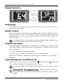
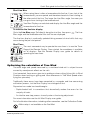
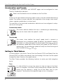
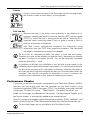
Quick Start Guide
Maxi and Dual Maxi
Display
Quick Start guide for the Maxi And Dual Maxi Display
Notice:
For full user documentation for the Micronet family and for other useful infomation
please refer to the CD-ROM supplied with your product, or to the raymarine website
at www.raymarine.com.
www.raymarine.com
Quick Start guide for the Maxi And Dual Maxi Display
Key Features
Simple to Install
Solar Powered: your Maxi Display is powered for life by the sun. The innovative
technology uses so little current and the power supply is so efficient, that the Maxi
display is independent from your boat's batteries.
Wireless: your Raymarine displays communicate by wireless, they can be sited
anywhere on your boat without disruption or cables.
Dedicated to Performance
Optimise your start: the Maxi Display's powerful functions for Distance and SpeedTrim to the line, Line Bias and Race Timer help you get the best possible start.
Enhance your performance with the built-in function for Wind Shift and indicators
for Accelerations and Trends.
Simplify your tidal navigation with the Maxi Display's Set, Drift, Turn and Course
to Steer functions.
True Wind correction: the Maxi Display incorporates sophisticated correction
technology to maximise the accuracy of True Wind calculations.(Airflow setup is not
available on the Dual Maxi)
Custom Pages allow you to display data such as target boat speed from your onboard computer on your Maxi Display. (Not available on the Dual Maxi)
Easy to Manage
Automatic data selection: the innovative Auto Leg function allows the display to
automatically show the information you need for each leg of the course.
Page Hiding means you can avoid data duplication on different displays,
minimising the time to select the pages you really need.
Wireless Remote control: your Maxi display can be controlled
and configured from anywhere in the boat using a Raymarine
Remote display.
Excellent visibility
The large, high contrast LCD gives the Maxi Display a wide angle of view and
ensures excellent visibility from anywhere on your boat.
The black background minimises disturbance to your night vision, and the
red/amber option allows you to choose the backlight colour of your display at night.
www.raymarine.com
1
Quick Start guide for the Maxi And Dual Maxi Display
Display Operation
Solar Panel
Upper Pane
Lower Pane
Battery
Charge | Status
Control Button
Terminology
All references to “Maxi Display” refer to both the Maxi and the Dual Maxi displays,
unless specifically stated.
Remote Control
Your Maxi Display is designed to be controlled using a Raymarine Remote Display.
See the Remote Display user guide for details of remote control mode. All
references to the
,
,
or
buttons refer to the appropriate button on the
Remote Display.
if a Remote Display is not available, your Maxi Display can be operated using
the control button, see the full user guide for details.
Chapters and Pages
The Maxi Display’s data screens are organised in a sequence of Chapters, each
containing Pages of related information. See page 6 for a diagram of all the data
pages available.
The
button scrolls through the chapters.
The
and
buttons scroll forward and back between pages.
When a new chapter is selected, the data page last selected for that chapter is
displayed.
Power Management and Battery Life
Power status is shown by two icons: battery level
and charge rate
bars showing, the higher the battery level/rate of charge.
. The more
If the internal battery is fully charged, the charge rate icon will always indicate
low.
Artificial light WILL NOT recharge the battery. Placing your Maxi Display close
to an artificial light will seriously damage the display. Only recharge in natural
daylight.
2
www.raymarine.com
Quick Start guide for the Maxi And Dual Maxi Display
Backlighting
To adjust the display backlighting press and hold
select from OFF, or levels 1,2,3.
, then use
and
to
Automatic Pages
You probably want a different page shown on your Maxi Display for each leg of the
course. The Maxi display makes this easy by providing a special page: the AUTO
LEG page. Using this feature, you can programme your Maxi Display to show
exactly the information you require for each leg of the course without the need to
manually change pages at each mark rounding.
For example, consider a boat with
three Maxi Displays on a mast
bracket. The diagram shows a
typical selection of pages for
different legs of the course.
Programming these pages into
the Autoleg page before the race
automatically shows the selected
information for the appropriate leg
of the course; leaving the tactician
free to concentrate on the race.
To programme the Autoleg page:
Use your Remote Display to select your Maxi Display for remote control.
It is a good idea to programme the remote control display list of your Remote
Display to show your Maxi Displays in the same order as their physical location
on the boat. See the Remote Display user guide.
Press and hold
Use
and
Then use
displayed.
to enter setup mode in the Autoleg chapter.
to select a leg.
, followed by
A further press of
and
to select the data page to be
confirms the selection.
When finished, press and hold
to exit setup mode.
you can select Simple or Advanced mode for configuring the legs. See the full
user guide for further details.
using the Page Hiding function to eliminate duplicate pages across displays
reduces the time and key presses required if a manual reconfiguration of the
data displayed becomes necessary. See the full user guide for details.
www.raymarine.com
3
Quick Start guide for the Maxi And Dual Maxi Display
Optimising your start with the Maxi Display
The Maxi display provides three functions to help you get a great start:
The Depart page
Approaching the start, it is vital to know your distance from the line and
whether you will arrive before or after the signal.
The large digits show your distance from the nearest point on the line in
distance units or boat-lengths. A negative distance shows that the boat
is to windward of the start line, not that the boat is on the course side of
the line; i.e. for a downwind start, a negative distance shows you are
approaching the line correctly.
The small digits show the change in speed (in speed units) required for you to arrive
at the line at the signal; a negative value means that you must decrease your speed
to avoid arriving early.
These calculations rely on GPS data, so they are subject to error, particularly as
the distance from the line becomes small. Do not rely on this information to
determine if you are over the line at the start. Rather, you should use the data to
help optimise your approach to the line.
To initialise the Depart page:
With the depart page displayed, approach one end of the start line as if starting;
press
when the bow touches the line. A popup page shows that the first line
position has been captured. Repeat at the other end of the line. The popup shows
the second line position has been captured.
Set your points as close to the ends of the line as possible.
To modify the start line points:
To modify one of the points, press
while at the correct location; the popup will
show that position 1 has been captured. Pressing
or
will allow you to set
the captured location to position 2. or to discard it (-).
The position is captured at the moment
4
is pressed.
www.raymarine.com
Quick Start guide for the Maxi And Dual Maxi Display
Start Line Bias
When racing there is often a favoured end to the line. If you start at the
favoured end, you are upwind and therefore ahead of a boat starting at
the other end of the line. The larger the Line Bias angle, the more you
can gain from starting at the favoured end.
Your Maxi Display can calculate and display the Line Bias angle and the
favoured end of the line.
To initialise the line bias display
Go to the Line Bias page, Sail directly along the start line, then press
Bias angle and the favoured end of the start line are displayed.
. The Line
The line bias display is continually updated taking account of wind shifts that may
occur during the pre-start period.
Start Timer
The most convenient way to operate the race timer is to use the Timer
Page of the Remote Display. Once started, the countdown is available
on all displays. See the Remote Display user guide for details of
operating the race timer.
Optimising the calculation of True Wind
The wind angle and speed measured by a masthead wind unit is subject to error
caused by aerodynamic effects on the sails.
If not corrected, these errors give rise to problems when sailing (false shifts in Wind
Direction when tacking or gybing and false differences in True Wind Speed when
flying the spinnaker).
Traditionally these errors have been corrected by a complex and time consuming
calibration process, but the Maxi Display has changed all that.
Raymarine has made two breakthroughs:
- Sophisticated built in corrections that dramatically reduce the errors for the
majority of boats.
- An intuitive one step process to easily enter a fine tuning adjustment.
For more information see the full Maxi Display user guide.
For full calibration information, including airflow correction, see the Calibration Guide.
Airflow setup is not available on the Dual Maxi.
www.raymarine.com
5
Quick Start guide for the Maxi And Dual Maxi Display
Acceleration and Trends
The Speed, SOG, VMG-WIND and VMG-WPT pages can be configured to show
Trend or Acceleration indicators.
Trends and Acceleration are not available on the Dual Maxi.
Arrows to the right indicate increasing speed, arrows to the left indicate decreasing
speed. The number of arrows indicates the magnitude of the change; more arrows
means a greater acceleration or a faster trend.
The sensitivity of the trend and acceleration indication can be configured in setup,
see the full user guide.
Acceleration mode
The arrows indicate whether the boat is accelerating or decelerating;
they are not shown when the speed is stable
Trend mode
The arrows show whether the overall speed trend is upwards or
downwards from a reference speed. By default, the reference speed is
calculated as a rolling average of the actual speed. Pressing
will set
the reference speed equal to the current boat speed (or SOG, VMG as
appropriate); the new reference speed will briefly be shown flashing and
may be edited using
and
.
Sailing in Tidal Waters
In tidal conditions, your boat's Course Over the Ground (COG) and Speed Over the
Ground (SOG) may differ considerably from the heading of the boat and the speed
through the water shown by the speed sensor.
The Maxi Display provides the following functions to make your tidal navigation
easier.
Turn
It is often difficult to assess the course to steer to keep on the direct
track to a waypoint. Your Maxi Display automatically indicates when the
course you are steering is taking you off the direct track to your
waypoint. The direction and required angle of turn is displayed.
6
www.raymarine.com
Quick Start guide for the Maxi And Dual Maxi Display
Course
Used in similar circumstances to the Turn page, the Course page shows
the course to steer to track directly to the waypoint.
Drift and Set
Because the boat is not always moving directly in the direction of its
compass heading you need to know the direction (SET) and the speed
(DRIFT) by which the boat is being pushed off course. Tactically this is
important when assessing when to tack or gybe to round a mark or
clear an obstruction or headland.
Your Maxi Display automatically calculates this information using
information from your GPS, boat speed and compass. The calculated
set angle is rounded to the nearest ten degrees.
Set and Drift as calculated includes the effect of both tide and leeway.
Therefore the value will be different on opposite tacks, depending on whether
the boat is sailing into or against the tide. This will be especially noticeable
when the tidal effect is small.
In conditions of little tide, this calculation is very sensitive to inaccuracies in the
calibration of your speed and compass transducers. It is not recommended that
you rely on the accuracy of this calculation in situations where the tide speed is
less than one Knot (a flashing indicator will alert you if the calculated values are
uncertain). See the full user guide for information on how to maximise the
accuracy of the calibration of your speed and heading transducers.
Performance Chapter
If you have an on-board computer connected to your Raymarine Wireless (NMEA)
interface, you can display data from the computer on your Maxi Displays using
Raymarine proprietary NMEA messages (PTAK). For example, you could calculate
and display “Distance to Layline”, “Target Speed”, “Corrected True Wind”, etc.
When such messages are detected on the network, The Performance Chapter, of six
free format screens, is automatically added to the chapter rollover.
Many PC navigation packages support Raymarine proprietary (PTAK) sentences, and
details of how to use the PTAK interface are available from the Raymarine web site.
Custom data pages are not available on the Dual Maxi Display.
www.raymarine.com
7
Quick Start guide for the Maxi And Dual Maxi Display
Data Chapters and Pages
CHAPTER
PAGES
RC
RC
Boat Speed
VMG to
Windward
VMG to
Waypoint
Depth
Minimum
Depth
Maximum
Depth
Apparent
Wind Speed
Apparent
Wind Angle
True
Wind Speed
RC
Log
Distance
Trip
Distance
Maximum
Speed
Average
Speed
True
Wind Angle
True Wind
Direction
Beaufort
Wind Force
Wind Shift
Pages hidden
by default
Maximum
True Wind
Not Available
on Dual Maxi
Not Available
on Dual Maxi
Longitude
Heading
Tack Course
Speed over
Ground
Course over
Ground
Drift and Set
Latitude
Bearing to
Waypoint
Turn
Course to
Waypoint
Distance to
Waypoint
Cross Track
Error
Time to Go
to Waypoint
Sea
Temperature
Time
Date
Power
Line Distance
and Speed
Auto Leg
Page
Free Format
Free Format
Free Format
Free Format
2
3
4
5
Only available on the Maxi Display - See page 7
Free Format
6
RC
Timer
Free Format
1
8
Line Bias
www.raymarine.com
www.raymarine.com