1
DATA PROJECTOR
MODEL
PG-LW3500
PG-LW3000
PG-LX3500
PG-LX3000
SETUP MANUAL
Connecting Pin Assignments............................................................. 2
RS-232C Specifications and Commands.......................................... 4
Operating the Projector Using the PJLinkTM Protocol................... 10
Setting up the Projector Network Environment................................ 11
1. Connecting the Projector to a Computer............................................. 12
2. Setting an IP Address for the Computer.............................................. 13
3. Setting up a Network Connection for the Projector............................. 15
Controlling the Projector via LAN.................................................... 17
Controlling the Projector Using Internet Explorer..................................... 17
Confirming the Projector Status (Status).................................................. 18
Controlling the Projector (Control)............................................................ 18
Setting and Adjusting the Projector (Settings & Adjustments)................. 19
Setting the Security (Network – Security)................................................. 19
Making General Settings for the Network (Network – General)............... 20
Setting for Sending E-mail when an Error Occurs
(Mail – Originator Settings)............................................................. 20
Setting Error Items and Destination Addresses to which E-mail is to be
Sent when an Error Occurs (Mail – Recipient Settings)................. 21
Setting Error Items and the URL that are to be Displayed
when an Error Occurs (Service & Support – Access URL)............. 21
Resetting the Lamp Timer of the Projector via LAN...................... 22
Troubleshooting................................................................................. 24
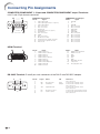
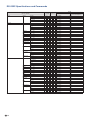
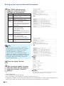
Connecting Pin Assignments
COMPUTER/COMPONENT 1, 2 input and COMPUTER/COMPONENT output Terminals:
mini D-sub 15 pin female connector
15
11
1
6
5
10
COMPUTER Input/Output
Pin No.
Signal
1. Video input (red)
2. Video input (green/sync on green)
3. Video input (blue)
4. Not connected
5. Not connected
6. Earth (red)
7. Earth (green/sync on green)
8. Earth (blue)
9. Not connected
10. GND
11. Not connected
12. Bi-directional data
13. Horizontal sync signal: TTL level
14. Vertical sync signal: TTL level
15. Data clock
COMPONENT Input/Output
Pin No.
Signal
1. PR (CR)
2. Y
3. PB (CB)
4. Not connected
5. Not connected
6. Earth (PR)
7. Earth (Y)
8. Earth (PB)
9. Not connected
10. Not connected
11. Not connected
12. Not connected
13. Not connected
14. Not connected
15. Not connected
Pin No.
1.
2.
3.
4.
5.
6.
7.
8.
9.
10.
Pin No.
11.
12.
13.
14.
15.
16.
17.
18.
19.
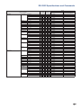
HDMI Terminal
18
2
19
1
Name
T.M.D.S. Data 2+
T.M.D.S. Data 2 Shield
T.M.D.S. Data 2–
T.M.D.S. Data 1+
T.M.D.S. Data 1 Shield
T.M.D.S. Data 1–
T.M.D.S. Data 0+
T.M.D.S. Data 0 Shield
T.M.D.S. Data 0–
T.M.D.S. Clock+
Name
T.M.D.S. Clock Shield
T.M.D.S. Clock–
CEC
Utility
SCL
SDA
DDC/CEC ground
+5V power
Hot plug detection
RS-232C Terminal: D-sub 9 pin male connector of the DIN-D-sub RS-232C adaptor
1
6
-2
5
9
Pin No.
1.
2.
3.
4.
5.
6.
7.
8.
9.
Signal
Name
I/O
RD
SD
Receive Data
Send Data
Input
Output
SG
Signal Ground
RS
CS
Request to Send
Clear to Send
Reference
Not connected
Connected to internal circuit
Connected to internal circuit
Not connected
Connected to internal circuit
Not connected
Connected to CS in internal circuit
Connected to RS in internal circuit
Not connected
Connecting Pin Assignments
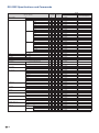
RS-232C Cable recommended connection: D-sub 9 pin female connector
5
9
1
6
Pin No.
1.
2.
3.
4.
5.
6.
7.
8.
9.
Signal
CD
RD
SD
ER
SG
DR
RS
CS
CI
Pin No.
1.
2.
3.
4.
5.
6.
7.
8.
9.
Signal
CD
RD
SD
ER
SG
DR
RS
CS
CI
Note
• Depending on the controlling device used, it may be necessary to connect Pin 4 and Pin 6 on the
controlling device (e.g. computer).
Projector
Pin No.
4
5
6
USB Terminal: Type B USB connector
4 3
Pin No.
1.
2.
3.
4.
Signal
VCC
USB–
USB+
SG
Computer
Pin No.
4
5
6
LAN Terminal: LAN (RJ-45)
Name
USB power
USB data–
USB data+
Signal Ground
Pin No.
1.
2.
3.
4.
Signal
TX+
TX–
RX+
Pin No.
5.
6.
7.
8.
Signal
RX–
8 ... 1
1 2
-3
RS-232C Specifications and Commands
Computer control
A computer can be used to control the projector by connecting an RS-232C serial control cable (cross
type, commercially available) to the projector. (See page 24 of the projectors operation manual for
connection.)
Communication conditions
Set the serial port settings of the computer to match that of the table.
Signal format: Conforms to RS-232C standard.
Parity bit: None
Baud rate*: 9,600 bps
Stop bit: 1 bit
Data length: 8 bits
Flow control: None
*Set the projector's baud rate to the same rate as used by the computer.
Basic format
Commands from the computer are sent in the following order: command, parameter, and return code.
After the projector processes the command from the computer, it sends a response code to the
computer.
Command format
C1
C2
C3
C4
Command 4-digit
P1
P2
P3
P4
Return code (0DH)
Parameter 4-digit
Response code format
Problem response (communication error or incorrect command)
Normal response
O
K
Return code (0DH)
E
R
R
Return code (0DH)
Info
• When controlling the projector using RS-232C commands from a computer, wait for at least 30 seconds
after the power has been turned on, and then transmit the commands.
• After sending an input selection or picture adjustment command and then receiving an “OK” response
code, the projector may take some time to process the command. If a second command is sent while the
projector is still processing the first command, you may receive an “ERR” response code. If this happens,
try resending the second command.
• When more than one code is being sent, send each command only after the response code for the
previous command from the projector is verified.
• “POWR????”, “TABN _ _ _ 1”, “TLPS _ _ _ 1”, “TPOW _ _ _ 1”, “TLPN _ _ _ 1”, “TLTT _ _ _ 1”,
“TLTM _ _ _ 1”, “TLTL _ _ _ 1”, “TNAM _ _ _ 1”, “MNRD _ _ _ 1”, “PJN0 _ _ _ 1”
−When the projector receives the special commands shown above:
*The on-screen display will not disappear.
*The “Auto Power Off” timer will not be reset.
−The special commands are available for applications that require continuous polling.
Note
• If an underbar (_) appears in the parameter column, enter a space.
• If an asterisk (*) appears in the parameter column, enter a value in the range indicated in brackets under
Control Contents.
-4
RS-232C Specifications and Commands
Commands
Example: When turning on the projector, make the following setting.
Computer
P
O
W
R
_
_
_
Projector
→
←
1
O
K
RETURN
CONTROL CONTENTS
Power
COMMAND
P O W R _
P O W R _
On
Off
Status
_
1 OK or ERR
OK
_
_
0 OK
OK or ERR
Status
T L P S _
_
_
1 0: Off, 1: On, 2: Retry
3: Waiting, 4: Lamp Error
0: Off, 4: Lamp Error
Power Status
T P O W _
T L P N _
_
_
1 1: On, 2: Cooling
0: Standby
_
_
1 1
T L T T _
T L T M _
T L T L _
_
_
1 0 – 9999(Integer)
_
_
1 0, 15, 30, 45
_
_
1 0% – 100%(Integer)
T N A M _
M N R D _
_
_
1 PGLX3000/PGLX3500/PGLW3000/PGLW3500
_
_
1 PG-LX3000/PG-LX3500/PG-LW3000/PG-LW3500
Projector Name Setting 1
(First 4 characters) *1
P J N 1
*
*
*
* OK or ERR
Projector Name Setting 2
(Middle 4 characters) *1
P J N 2
*
*
*
* OK or ERR
Projector Name Setting 3
(Last 4 characters) *1
P J N 3
*
*
*
* OK or ERR
Projector Name Check
P J N 0
COMPUTER1
I
COMPUTER2 *2
I
HDMI
I
VIDEO
I
Input RGB Check
I
R G B ? ? ? ? 1: COMPUTER1, 2: COMPUTER2, ERR
3: HDMI, ERR
V E D ? ? ? ? 1: VIDEO or ERR
Usage Time(Hour)
Usage Time(Minute)
Life(Percentage)
Model Name Check
Model Name Check
Input Change
_
0
Quantity
Name
Standby mode
(or 30-second startup time)
Power ON
P O W R ? ? ? ? 1
T A B N _ _ _ 1 0: Normal
1: Temp High
8: Lamp Life 5% or less
16: Lamp Burn-out
32: Lamp Ignition Failure
Projector Condition
Lamp
PARAMETER
0: Normal
1: Temp High
2: Fan Error
4: Cover Open
8: Lamp Life 5% or less
16: Lamp Burn-out
32: Lamp Ignition Failure
64: Temp Abnormally High
_
_
_
1 Projector Name
R G B _
R G B _
_
_
1 OK or ERR
ERR
_
_
2 OK or ERR
ERR
R G B _
V E D _
_
_
3 OK or ERR
ERR
_
_
1 OK or ERR
ERR
Input Video Check
I
Input Mode Check
I M O D ? ? ? ? 1: RGB, 2: VIDEO
Input Check
I
ERR
ERR
Volume up/down(-10 – +10)
C H K ? ? ? ? 1: COMPUTER1, 2: COMPUTER2, ERR
3: HDMI, 4: VIDEO
V O L A _ _ * * OK or ERR
ERR
V O U D _ * * * OK or ERR
ERR
Keystone
-80 – +80
K E Y S
AV Mute
On
Volume
Volume(0 – 60)
*
I M B K _
I M B K _
Off
Freeze
On
Off
Auto Sync
Start
Resize
COMPUTER1
Normal
16:9
Native
Full
Border (PG-LX3000/LX3500)
Area Zoom
V-Stretch
COMPUTER2
Normal
16:9
Native
Full
Border (PG-LX3000/LX3500)
Area Zoom
V-Stretch
HDMI
Normal
16:9
Native
Full
Border (PG-LX3000/LX3500)
Area Zoom
V-Stretch
*
_
*
_
1 OK or ERR
ERR
_
_
0 OK or ERR
ERR
F R E Z _
F R E Z _
_
_
1 OK or ERR
ERR
_
_
0 OK or ERR
ERR
A D J S _
R A S R _
_
_
1 OK or ERR
ERR
_
_
1 OK or ERR
ERR
R A S R _
R A S R _
R A S R _
R A S R _
_
_
2 OK or ERR
ERR
_
_
3 OK or ERR
ERR
_
_
5 OK or ERR
ERR
_
_
6 OK or ERR
ERR
R A S R _
R A S R _
_
1 0 OK or ERR
ERR
_
ERR
R B S R _
R B S R _
_
_
1 1 OK or ERR
_ 1 OK or ERR
_ 2 OK or ERR
R B S R _
R B S R _
_
_
3 OK or ERR
ERR
_
_
5 OK or ERR
ERR
R B S R _
R B S R _
R B S R _
R C S R _
_
_
6 OK or ERR
ERR
_
1 0 OK or ERR
ERR
_
ERR
R C S R _
R C S R _
_
1 1 OK or ERR
_ 1 OK or ERR
_ 2 OK or ERR
_
_
3 OK or ERR
ERR
R C S R _
R C S R _
_
_
5 OK or ERR
ERR
_
_
6 OK or ERR
ERR
R C S R _
R C S R _
_
1 0 OK or ERR
ERR
_
1 1 OK or ERR
ERR
_
* OK or ERR
ERR
ERR
ERR
ERR
ERR
-5
RS-232C Specifications and Commands
RETURN
CONTROL CONTENTS
Resize
VIDEO
COMMAND
Normal
16:9
Border (PG-LX3000/LX3500)
Area Zoom
V-Stretch
All Reset
COMPUTER1 Input
Picture Mode
Standard
Presentation
Movie
Game
sRGB
Standby mode
(or 30-second startup time)
R A S V _
R A S V _
_
_
1 OK or ERR
ERR
_
_
2 OK or ERR
ERR
R A S V _
R A S V _
_
_
3 OK or ERR
ERR
_
1 0 OK or ERR
ERR
R A S V _
A L R E _
_
ERR
_
1 1 OK or ERR
_ 1 OK or ERR
R A P S _
R A P S _
_
1 0 OK or ERR
ERR
_
1 1 OK or ERR
ERR
R A P S _
R A P S _
_
1 2 OK or ERR
ERR
_
1 3 OK or ERR
ERR
R A P S _
R A P I _
R A B R _
R A R D _
_
1 4 OK or ERR
ERR
*
*
* OK or ERR
ERR
*
*
* OK or ERR
ERR
*
*
* OK or ERR
ERR
*
*
* OK or ERR
ERR
*
*
* OK or ERR
ERR
ERR
-30 – +30
Bright
-30 – +30
Red
-30 – +30
Blue
-30 – +30
Color
-30 – +30
R A B E _
R A C O _
Tint
-30 – +30
R A T
_
*
*
* OK or ERR
ERR
Sharp
-30 – +30
* OK or ERR
ERR
-1 – +1
*
_
*
CLR Temp
R A S H _
R A C T _
* OK or ERR
ERR
BrilliantColor™
0 – +2
R A W E _
_
*
_
* OK or ERR
ERR
Film Mode
Auto
R A F M _
_
_
0 OK or ERR
ERR
Off
R A F M _
R A N R _
_
_
_
_
1 OK or ERR
ERR
1 OK or ERR
ERR
_
_
2 OK or ERR
ERR
Level 3
R A N R _
R A N R _
_
_
3 OK or ERR
ERR
_
_
1 OK or ERR
ERR
Auto
R A R E _
I A S I _
_
_
0 OK or ERR
ERR
RGB
I
A S
I
_
_
_
1 OK or ERR
ERR
YPbPr
I
A S
I
_
_
_
2 OK or ERR
ERR
AUDIO 1
R A A
I
_
_
_
1 OK or ERR
ERR
AUDIO 2
R A A
I
_
_
_
2 OK or ERR
ERR
Standard
R B P S _
R B P S _
_
1 0 OK or ERR
ERR
_
1 1 OK or ERR
ERR
R B P S _
R B P S _
_
1 2 OK or ERR
ERR
_
1 3 OK or ERR
ERR
R B P S _
R B P I _
_
1 4 OK or ERR
ERR
*
*
* OK or ERR
ERR
R B B R _
R B R D _
*
*
* OK or ERR
ERR
*
*
* OK or ERR
ERR
*
*
* OK or ERR
ERR
*
*
* OK or ERR
ERR
Level 1
Level 2
Picture Reset
Signal Type
Audio Input
Picture Mode
Presentation
Movie
Game
sRGB
I
Contrast
-30 – +30
Bright
-30 – +30
Red
-30 – +30
Blue
-30 – +30
Color
-30 – +30
R B B E _
R B C O _
Tint
-30 – +30
R B T
_
*
*
* OK or ERR
ERR
Sharp
-30 – +30
* OK or ERR
ERR
-1 – +1
*
_
*
CLR Temp
R B S H _
R B C T _
* OK or ERR
ERR
BrilliantColor™
0 – +2
R B W E _
_
*
_
* OK or ERR
ERR
Film Mode
Auto
R B F M _
_
_
0 OK or ERR
ERR
Off
R B F M _
R B N R _
_
_
_
_
1 OK or ERR
ERR
1 OK or ERR
ERR
R B N R _
R B N R _
_
_
2 OK or ERR
ERR
_
_
3 OK or ERR
ERR
_
_
1 OK or ERR
ERR
_
_
0 OK or ERR
ERR
_
_
1 OK or ERR
ERR
YPbPr
R B R E _
I B S I _
I B S I _
I B S I _
_
_
2 OK or ERR
ERR
AUDIO 1
R B A
I
_
_
_
1 OK or ERR
ERR
AUDIO 2
R B A
I
_
_
_
2 OK or ERR
ERR
DNR
Level 1
Level 2
Level 3
Picture Reset
Signal Type
Auto
RGB
Audio Input
-6
Power ON
Contrast
DNR
COMPUTER2 Input
PARAMETER
I
RS-232C Specifications and Commands
RETURN
CONTROL CONTENTS
HDMI Input
Picture Mode
COMMAND
Standard
Presentation
Movie
R C P S _
R C P S _
R C P S _
Power ON
Standby mode
(or 30-second startup time)
_
1 0 OK or ERR
ERR
_
1 1 OK or ERR
ERR
_
1 2 OK or ERR
ERR
_
1 3 OK or ERR
ERR
sRGB
R C P S _
R C P S _
_
1 4 OK or ERR
ERR
Contrast
-30 – +30
R C P
_
*
*
* OK or ERR
ERR
Bright
-30 – +30
*
*
* OK or ERR
ERR
Red
-30 – +30
R C B R _
R C R D _
*
*
* OK or ERR
ERR
Blue
-30 – +30
*
*
* OK or ERR
ERR
Color
-30 – +30
R C B E _
R C C O _
*
*
* OK or ERR
ERR
Tint
-30 – +30
R C T
_
*
*
* OK or ERR
ERR
Sharp
-30 – +30
* OK or ERR
ERR
-1 – +1
*
_
*
CLR Temp
R C S H _
R C C T _
* OK or ERR
ERR
BrilliantColor™
0 – +2
R C W E _
_
*
_
* OK or ERR
ERR
Film Mode
Auto
R C F M _
_
_
0 OK or ERR
ERR
Off
R C F M _
R C N R _
_
_
_
_
1 OK or ERR
ERR
1 OK or ERR
ERR
_
_
2 OK or ERR
ERR
Level 3
R C N R _
R C N R _
_
_
3 OK or ERR
ERR
_
_
1 OK or ERR
ERR
Auto
R C R E _
I C S I _
_
_
0 OK or ERR
ERR
RGB
I
C S
I
_
_
_
1 OK or ERR
ERR
YPbPr
I
C S
I
_
_
_
2 OK or ERR
ERR
AUDIO 1
R C A
I
_
_
_
1 OK or ERR
ERR
AUDIO 2
R C A
I
_
_
_
2 OK or ERR
ERR
HDMI
R C A
I
_
_
_
3 OK or ERR
ERR
Auto
H M C D _
H M C D _
_
_
0 OK or ERR
ERR
_
_
1 OK or ERR
ERR
H M C D _
V A P S _
_
_
2 OK or ERR
ERR
Game
DNR
Level 1
Level 2
Picture Reset
Signal Type
Audio Input
Dynamic
Range
Standard
Enhanced
VIDEO Input
PARAMETER
Picture Mode
Standard
Presentation
Movie
Game
I
I
_
1 0 OK or ERR
ERR
V A P S _
V A P S _
V A P S _
V A P I _
_
1 1 OK or ERR
ERR
_
1 2 OK or ERR
ERR
_
1 3 OK or ERR
ERR
*
*
* OK or ERR
ERR
V A B R _
V A R D _
*
*
* OK or ERR
ERR
*
*
* OK or ERR
ERR
*
*
* OK or ERR
ERR
*
*
* OK or ERR
ERR
Contrast
-30 – +30
Bright
-30 – +30
Red
-30 – +30
Blue
-30 – +30
Color
-30 – +30
V A B E _
V A C O _
Tint
-30 – +30
V A T
_
*
*
* OK or ERR
ERR
Sharp
-30 – +30
V A S H _
V A C T _
*
_
*
* OK or ERR
ERR
ERR
_
*
_
* OK or ERR
V A W E _
V A F M _
* OK or ERR
ERR
_
_
0 OK or ERR
ERR
V A F M _
V A N R _
_
_
1 OK or ERR
ERR
_
_
1 OK or ERR
ERR
_
_
2 OK or ERR
ERR
Level 3
V A N R _
V A N R _
_
_
3 OK or ERR
ERR
_
_
1 OK or ERR
ERR
AUDIO 1
V A R E _
V A A I _
_
_
1 OK or ERR
ERR
AUDIO 2
V A A
_
_
_
2 OK or ERR
ERR
CLR Temp
-1 – +1
BrilliantColor™
0 – +2
Film Mode
Auto
Off
DNR
Level 1
Level 2
Picture Reset
Audio Input
I
I
-7
RS-232C Specifications and Commands
RETURN
CONTROL CONTENTS
C.M.S. Setting
COMMAND
On
Off
C.M.S.
Hue
Red
Yellow
Green
Cyan
Blue
Magenta
Reset
Saturation
Red
PARAMETER
Power ON
Standby mode
(or 30-second startup time)
C M C S _
C M C S _
_
1 1 OK or ERR
ERR
_
0 0 OK or ERR
ERR
C M H R _
C M H Y _
*
*
* OK or ERR
ERR
*
*
* OK or ERR
ERR
C M H G _
C M H C _
*
*
* OK or ERR
ERR
*
*
* OK or ERR
ERR
C M H B _
C M H M _
*
*
* OK or ERR
ERR
*
_
*
_
* OK or ERR
ERR
2 OK or ERR
ERR
C M R E _
C M S R _
*
*
* OK or ERR
ERR
C M S Y _
C M S G _
C M S C _
C M S B _
*
*
* OK or ERR
ERR
*
*
* OK or ERR
ERR
*
*
* OK or ERR
ERR
*
*
* OK or ERR
ERR
C M S M _
C M R E _
*
_
*
_
* OK or ERR
ERR
3 OK or ERR
ERR
C M V R _
C M V Y _
*
*
* OK or ERR
ERR
*
*
* OK or ERR
ERR
C M V G _
C M V C _
*
*
* OK or ERR
ERR
*
*
* OK or ERR
ERR
*
*
* OK or ERR
ERR
*
_
*
_
* OK or ERR
ERR
4 OK or ERR
ERR
C.M.S. All Reset
C M V B _
C M V M _
C M R E _
C M R E _
_
_
1 OK or ERR
ERR
Clock
-150 – +150
I
*
*
* OK or ERR
ERR
Phase
-30 – +30
I
*
N P H _
*
*
* OK or ERR
ERR
H-position
-150 – +150
I
A H P
V-position
-60 – +60
I
Yellow
Green
Cyan
Blue
Magenta
Reset
Value
Red
Yellow
Green
Cyan
Blue
Magenta
Reset
Fine Sync Adjustment Reset
I
N C L
*
A V P _
A R E _
*
*
* OK or ERR
ERR
*
_
*
_
* OK or ERR
ERR
1 OK or ERR
ERR
Image Shift
-96 – +96 (PG-LX3000/LX3500)
-40 – +40 (PG-LW3000/LW3500)
L N D S _
*
*
*
OK or ERR
ERR
Overscan
On
_
_
1 OK or ERR
ERR
Off
O V S N _
O V S N _
_
_
0 OK or ERR
ERR
On
I M D
I
_
_
_
1 OK or ERR
ERR
Off
I M D
I
_
_
_
0 OK or ERR
ERR
M E S Y _
M E S Y _
_
_
1 OK or ERR
ERR
_
_
2 OK or ERR
ERR
M E S Y _
M E S Y _
_
_
3 OK or ERR
ERR
_
_
4 OK or ERR
ERR
M E S Y _
M E S Y _
_
_
5 OK or ERR
ERR
_
_
6 OK or ERR
ERR
M E S Y _
M E S Y _
_
_
7 OK or ERR
ERR
_
_
8 OK or ERR
ERR
I M B G _
I M B G _
_
_
1 OK or ERR
ERR
_
_
3 OK or ERR
ERR
I M B G _
T H M D _
_
_
4 OK or ERR
ERR
_
_
1 OK or ERR
ERR
_
_
0 OK or ERR
ERR
On
T H M D _
A A D J _
_
_
1 OK or ERR
ERR
Off
A A D J
_
_
_
0 OK or ERR
ERR
On
A P O W _
A P O W _
_
_
1 OK or ERR
ERR
_
_
0 OK or ERR
ERR
_
_
1 OK or ERR
ERR
Off
A R E S _
A R E S _
_
_
0 OK or ERR
ERR
Quick Start
M O U T
_
_
_
1 OK or ERR
ERR
Eco
M O U T
_
_
_
0 OK or ERR
ERR
STANDBY Audio Out
On
S A O T
_
_
_
1 OK or ERR
ERR
S A O T
PRJ Mode
Reverse
OSD Display
Video System
Auto
PAL
SECAM
NTSC4.43
NTSC3.58
PAL-M
PAL-N
PAL-60
Background
Logo
Blue
None
Eco+Quiet
On
Off
Auto Sync
Auto Power Off
Off
Auto Restart
STANDBY Mode
On
_
_
_
0 OK or ERR
ERR
_
_
1 OK or ERR
ERR
Off
I M R E _
I M R E _
_
_
0 OK or ERR
ERR
On
I M I
_
_
1 OK or ERR
ERR
Off
I M I
N _
N _
_
_
0 OK or ERR
ERR
Off
Invert
-8
On
RS-232C Specifications and Commands
RETURN
CONTROL CONTENTS
Language
English
Deutsch
Español
Nederlands
M E L A _
M E L A _
M E L A _
M E L A _
M E L A _
Power ON
Standby mode
(or 30-second startup time)
_
_
1 OK or ERR
ERR
_
_
2 OK or ERR
ERR
_
_
3 OK or ERR
ERR
_
_
4 OK or ERR
ERR
_
_
5 OK or ERR
ERR
_
6 OK or ERR
ERR
_
_
7 OK or ERR
ERR
_
_
8 OK or ERR
ERR
_
_
9 OK or ERR
ERR
M E L A _
M E L A _
_
1 0 OK or ERR
ERR
_
1 1 OK or ERR
ERR
M E L A _
M E L A _
_
1 2 OK or ERR
ERR
_
1 3 OK or ERR
ERR
_
1 4 OK or ERR
ERR
Türkçe
M E L A _
M E L A _
_
1 5 OK or ERR
ERR
_
1 6 OK or ERR
ERR
Magyar
M E L A _
M E L A _
_
1 7 OK or ERR
ERR
M E L A _
S E G U _
_
ERR
S E G U _
A S P K _
A S P K _
_
1 8 OK or ERR
_ 1 OK or ERR
_ 0 OK or ERR
_
_
1 OK or ERR
ERR
_
_
0 OK or ERR
ERR
T F R Q _
T F R Q _
_
_
1 kHz(***.* or ERR)
ERR
_
_
2 Hz(***.* or ERR)
ERR
H L M D _
H L M D _
_
_
0 OK or ERR
ERR
_
_
1 OK or ERR
ERR
Svenska
M E L A _
M E L A _
Português
M E L A _
M E L A _
polski
Tiéng
Setup Guide
On
Internal Speaker
On
Off
Off
Horizontal
Vertical
Fan Mode
PARAMETER
_
Français
Italiano
RGB Frequency Check
COMMAND
Normal
High
_
ERR
ERR
Input Search *3
Start
I
S E S _
_
_
1 OK or ERR
ERR
Video Setup
0 IRE
V
I
S U _
_
_
0 OK or ERR
ERR
7.5 IRE
V
I
S U _
_
_
1 OK or ERR
ERR
Wall Color
Off
W L C O _
_
_
0 OK or ERR
ERR
Blackboard
W L C O _
_
_
1 OK or ERR
ERR
Whiteboard
W L C O _
_
_
2 OK or ERR
ERR
Green
W L C O _
_
_
3 OK or ERR
ERR
Yellow green
W L C O _
_
_
4 OK or ERR
ERR
Yellow
W L C O _
_
_
5 OK or ERR
ERR
Orange
W L C O _
_
_
6 OK or ERR
ERR
Pink
W L C O _
_
_
7 OK or ERR
ERR
Purple
W L C O _
_
_
8 OK or ERR
ERR
Blue
W L C O _
_
_
9 OK or ERR
ERR
Greenish blue
W L C O _
_
1 0 OK or ERR
ERR
On
Q S M N _
_
_
0 OK or ERR
ERR
Off
Q S M N _
_
_
1 OK or ERR
ERR
Input
R B S E _
_
_
0 OK or ERR
ERR
Monitor Output
R B S E _
_
_
1 OK or ERR
ERR
Off
3 D E N _
_
_
0 OK or ERR
ERR
On
3 D E N _
_
_
1 OK or ERR
ERR
3 D
V _
_
_
1 OK or ERR
ERR
Off
C L C A _
_
_
0 OK or ERR
ERR
CC1
C L C A _
_
_
1 OK or ERR
ERR
CC2
C L C A _
_
_
2 OK or ERR
ERR
Reset Network Setting
L N R E _
_
_
1 OK or ERR
OK or ERR
Restart Network
L R E S _
_
_
1 OK or ERR
Lamp Timer Reset *5
L P R E 0 0 0 1 ERR
Quick Start Menu
COMPUTER2 Select *4
DLP ® LinkTM
DLP® LinkTM Invert
Closed Caption
(For Americas only)
I
OK or ERR
OK or ERR
*1 For setting the projector name, send the commands in the order of PJN1, PJN2 and PJN3.
*2 When “COMPUTER2 Select” is set to “Monitor Output”, you may receive an “ERR” response code.
*3 When the next command is sent during input search, you may receive an “ERR” response code, and the
input search is canceled.
*4 When “COMPUTER2” is selected in the INPUT list, “COMPUTER2 Select” cannot be set to “Monitor
Output”.
*5 The Lamp Timer Reset command is available only in standby mode.
-9
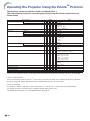
Operating the Projector Using the PJLinkTM Protocol
The projector conforms with the PJLinkTM standard Class 1.
The commands to be used in controlling the projector by the PJLinkTM protocol are as
shown below.
Power Control
CONTROL CONTENTS
Off
On
Power Status Query
COMMAND
RETURN
P O W R _
0
OK or ERR3
P O W R _
1
OK or ERR3
P O W R _
?
0: Standby Mode
1: Power On
2: Standby (Cooling)
3: Power On (Warming up)
Input List Query
Input Change
I
N S T
_
?
COMPUTER1
I
N P T
_
1 1
11 12 21 31
OK or ERR3
COMPUTER2
I
N P T
_
1 2
OK or ERR3
HDMI
I
N P T
_
3 1
OK or ERR3
VIDEO
I
N P T
_
2 1
OK or ERR3
I
N P T
_
?
11: COMPUTER1
Input Status Query
12: COMPUTER2
31: HDMI
21: VIDEO
or ERR3
AV Mute
AV Mute Status Query
Off
A V M T
_
3 0
OK or ERR3
On
A V M T
_
3 1
OK or ERR3
A V M T
_
?
30: Off
31: On
or ERR3
Lamp Query
L A M P _
?
Error Condition Query
E R S T
?
1st Number: Lamp Usage Time (Hour)
2nd Number: 0: Lamp Off 1: Lamp on
_
1st Byte: Fan Error Status
2nd Byte: Lamp Error Status
3rd Byte: Temp. Error Status
4th Byte: Cover Open Status
5th Byte: Not Used, Return 0
6th Byte: Other Error Status
0: No Error Detected
1: Warning
2: Error Detected
Projector Name Query *
N A M E _
?
Projector Name
Manufacture Name Query
I
N F 1
_
?
SHARP
Pruduct Name Query
I
N F 2
_
?
PG-LX3000/PG-LX3500/PG-LW3000/PG-LW3500
Other Information Query
I
N F O _
?
Not used
Class Information Query
C L S S _
?
1
* You can set “Projector Name” at “Making General Setting for the Network (Network-General)” on page 20.
PJLinkTM Authentication:
The password to be used for PJLinkTM is the same as the one you have set in “Setting the Security (NetworkSecurity)” (page 19). When operating without authentication, do not set a password.
PJLinkTM Compliant:
This product conforms with the PJLink standard Class 1 and all Class 1 commands are implemented.
This product confirms with the PJLink standard specification version 1.00.
For additional information, visit “http://pjlink.jbmia.or.jp/english/”.
-10
Setting up the Projector Network Environment
This section describes the basic procedure for using the projector via the network.
If the network is already constructed, the projector's network settings may need to be
changed. Please consult your network administrator for assistance with these settings.
You can make network settings both on the projector and on the computer. The following
procedure is for making settings on the computer.
Network settings on the computer
1. Connecting the projector to a computer
Connect a LAN cable (Category 5, cross-over type) between the computer and projector.
LAN cable
(commercially available)
Page 12
2. Setting an IP address for the computer
Adjust the IP settings of the computer to enable one-to-one communications with the projector.
Temporarily change
the computer's IP
address.
Pages 13, 14
3. Setting up a network connection for the projector
Adjust the projector network settings to conform to your network.
Use Internet Explorer
(version 6.0 or later)
to make various
projector settings.
Pages 15, 16
• Microsoft®, Windows®are registered trademarks of Microsoft Corporation in the United States and/or
other countries.
• PJLink is a registered trademark or an application trademark in Japan, the United States, Canada, E.U.,
China and/or other countries/regions.
• All other company or product names are trademarks or registered trademarks of their respective
companies.
-11
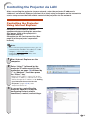
Setting up the Projector Network Environment
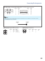
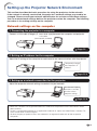
1.Connecting the Projector
to a Computer
Establishing a one-to-one connection from
the projector to a computer. Using a
commercially available LAN cable (UTP
cable, Category 5, cross-over type) you can
configure the projector via the computer.
1 Disconnect the computer's LAN
cable from the existing network.
A LAN cable being
connected to the network
2 Connect a commercially available
LAN cable (UTP cable, Category 5,
cross-over type) to the projector's
LAN terminal and connect the
other end of the cable to the
computer's LAN terminal.
LAN cable
(cross-over type, commercially available)
3 Plug the power cord into the AC
socket of the projector.
4 Turn on the computer.
ON
Info
Confirm that the LINK LED on the rear of the
projector illuminates. If the LINK LED does not
illuminate, check the following:
• The LAN cable is properly connected.
• The power switches of both the projector and
the computer are on.
This completes the connection. Now proceed to “2. Setting an IP Address for the Computer”.
-12
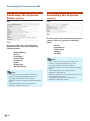
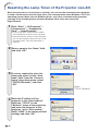
Setting up the Projector Network Environment
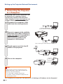
2.Setting an IP Address for
the Computer
The following describes how to make
settings in Windows Vista®.
1 Log on the network using the
administrator's account for the
computer.
2 Click “start”, and click “Control
Panel”.
2
1
3 Click “View network status and
tasks” of “Network and Internet”,
and click “Local Area Connection”
in the new window.
•This manual uses examples to explain the
operations in Category View. If you are using
Classic View, double-click “Network and
Sharing Center”.
1
2
“Properties”.
4 Click
•When the user account control display is
displayed, click “Continue”.
1
-13
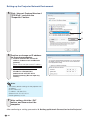
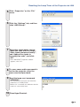
Setting up the Projector Network Environment
5 Click “Internet Protocol Version 4
(TCP/IPv4)”, and click the
“Properties” button.
1
2
6 Confirm or change an IP address
for the setup computer.
1Confirm and note the current IP
address, Subnet mask and Default
gateway.
Make sure to note the current IP address,
Subnet mask and Default gateway as you
will be required to reset them later.
2Set temporarily as follows:
IP address: 192.168.150.3
Subnet mask: 255.255.255.0
Default gateway: (Do not input any
values.)
Note
• The factory default settings for the projector are
as follows:
DHCP Client: OFF
IP address: 192.168.150.2
Subnet mask: 255.255.255.0
Default gateway: 0.0.0.0
7 After setting, click the “OK”
button, and then restart the
computer.
After confirming or setting, proceed to “3. Setting up Network Connection for the Projector”.
-14
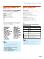
Setting up the Projector Network Environment
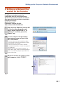
3. Setting up a Network Connection for the Projector
Settings for such items as the projector's
IP address and subnet mask are
compatible with the existing network.
Set each item on the projector as follows.
(See page 62 of the projector's operation
manual for setting.)
DHCP Client: Off
IP Address: 192.168.150.002
Subnet Mask: 255.255.255.000
1
Start Internet Explorer (version 6.0
or later) on the computer, and
enter “http://192.168.150.2/” in
“Address”, and then press the
“Enter” key.
2
If a user name and a password
have not yet been set, just click
the “OK” button.
• If a user name and a password have been
set, input the user name and the password,
and click the “OK” button.
• If the user name or password is entered
incorrectly three times, an error message will
be displayed.
• When you are using Internet Explorer 7 or
later, other setup screen may be displayed. In
this case, make the proper adjustments for
the setup screen.
3
When the screen as shown on the
right appears, click “TCP/IP”.
-15
Setting up the Projector Network Environment
4 The TCP/IP setting screen
appears, ready for network
settings for the projector.
Items
Setting example / Remarks
New
You can set the password to protect
Password the TCP/IP setting.
DHCP
Client
Select “ON” or “OFF” to determine
whether to use DHCP Client.
IP
Address
You can set this item when “DHCP
Client” is set to “OFF”.
Factory default setting: 192.168.150.2
Enter an IP address appropriate for
the network.
Subnet
Mask
You can set this item when “DHCP
Client” is set to “OFF”.
Factory default setting:
255.255.255.0
Set the subnet mask to the same as
that of the computer and equipment
on the network.
Default
Gateway
You can set this item when “DHCP
Client” is set to “OFF”.
Factory default setting: 0.0.0.0
* When not in use, set to “0.0.0.0”.
DNS
Server
Factory default setting: 0.0.0.0
* When not in use, set to “0.0.0.0”.
Note
• Confirm the existing network's segment (IP
address group) to avoid setting an IP address
that duplicates the IP addresses of other
network equipment or computers. If
“192.168.150.2” is not used in the network
having an IP address of “192.168.150.XXX”, you
don't have to change the projector IP address.
• For details about each setting, consult your
network administrator.
5 Click the “Apply” button.
6 The set values appear. Confirm
that the values are set properly,
and then click the “Confirm”
button.
• Close the browser.
• This completes the network settings.
• After setting items, wait for about 15 seconds and then re-access.
• Change the IP address of the setting computer back to its original address, which you have noted down in
Step 6-1 on page 14, and then connect the computer and the projector to the network.
-16
Controlling the Projector via LAN
After connecting the projector to your network, enter the projector IP address in
“Address” on Internet Explorer (version 6.0 or later) using a computer on the network to
start a setup screen that will enable control of the projector via the network.
Controlling the Projector
Using Internet Explorer
Complete connections to external
equipment before starting the operation.
(See pages 22-26 of the projector's
operation manual.)
Complete the AC cord connection. (See
page 26 of the projector's operation
manual.)
Note
• When connecting the projector to the LAN, use
a commercially available LAN cable (UTP cable,
Category 5, cross-over type). When
connecting the projector to a hub, use a
straight-through cable.
1
Start Internet Explorer on the
computer.
2
Enter “http://” followed by the
projector IP address set by the
procedure on page 16 followed by
“/” in “Address”, and then press
the “Enter” key.
• When “DHCP Client” is set to “Off” on the
projector, IP address is 192.168.150.2. If you
did not change the IP address in “3. Setting
up a Network Connection for the
Projector” (pages 15-16), enter
“http://192.168.150.2/”.
3
A screen for controlling the
projector appears, ready for
performing various status
conditions, control, and settings.
-17
Controlling the Projector via LAN
Confirming the Projector
Status (Status)
2
Controlling the Projector
(Control)
30
1
On this screen, you can perform projector
control. You can control the following
items:
On this screen, you can confirm the
projector status. You can confirm the
following items:
•MAC Address
•Power
•Condition
•Lamp Timer
•Lamp Life
•Input
•Signal Info
•Serial Number
Note
• If you click the “Refresh” button before the
screen is displayed completely, an error
message (“Server Busy Error”) will be
displayed. Wait for a moment and then operate
again.
• For details about each item, refer to the
projector's operation manual.
-18
•Power
•Input Select
•Audio Input
•Volume
•AV Mute
Note
• If you click the “Refresh” button before the
screen is displayed completely, an error
message (“Server Busy Error”) will be
displayed. Wait for a moment and then operate
again.
• You cannot operate this page while the
projector is warming up.
• While the projector is in standby mode, you can
only control “Power ON”.
• For details about each item, refer to the
projector's operation manual.
Controlling the Projector via LAN
Setting and Adjusting the
Projector (Settings & Adjustments)
Setting the Security
(Network – Security)
Example: “Picture” screen display for COMPUTER1
On these screens, you can make projector
settings or adjustments. You can set or
adjust the following items:
•
•
•
•
•
•
•
•
•
•
•
•
•
•
•
Picture Mode
CLR Temp
BrilliantColorTM
Film Mode
DNR
Eco + Quiet
Resolution Setting
Signal Type
Dynamic Range
Video System
Video Setup
Resize
Overscan
OSD Display
Background
•
•
•
•
•
•
•
•
•
•
•
•
•
•
Setup Guide
Projection Mode
Wall Color
OSD Language
Auto Sync
Auto Power Off
Auto Restart
Internal Speaker
Fan Mode
Quick Start Menu
COMPUTER2 Select
DLP® LinkTM
DLP® LinkTM Invert
All Reset
On this screen, you can make settings
relating to security.
Items
Description
User Name
Setting of user name for security
protection.
Password
Setting of password for security
protection.
Accept IP
Address
It is possible to set up to three IP
addresses allowing connection to the
projector.
All IP
Addresses
No limits are set to IP addresses
connecting to the projector.
From only
specific IP
addresses
For security improvement, only an IP
address set by “Address 1-3” can be
connected to the projector.
Note
Note
• If you click the “Refresh” button before the
screen is displayed completely, an error
message (“Server Busy Error”) will be
displayed. Wait for a moment and then operate
again.
• You cannot operate this page while the
projector is warming up.
• For details about each item, refer to the
projector's operation manual.
• User Name and Password can be up to 8
characters.
• You can input the characters below:
a-z, A-Z, 0-9, -, _
-19
Controlling the Projector via LAN
Making General Settings for
the Network (Network - General)
Setting for Sending E-mail
when an Error Occurs
(Mail – Originator Settings)
On this screen, you can make general
settings relating to the network.
Items
Description
Projector
Name
Setting the projector name.
Auto Logout
Time
Setting the time interval in which the
projector will be automatically
disconnected from the network in units
of a minute (from 1 to 65535 minutes).
If the set value is made 0, the Auto
Logout function is disabled.
Data Port
Setting the TCP port number used
when exchanging data with the
projector (from 1025 to 65535).
Search Port
Setting the port number used when
searching for the projector (from 1025
to 65535).
After clicking the “Apply” button, the set
values appear. Confirm that the values are
set properly, and then click the “Confirm”
button.
Note
• After setting items, wait for about 15 seconds
and then re-access.
• Projector Name can be up to 12 characters.
• You can input the characters below:
A-Z, 0-9, -, _, (,), space
(When “a-z” are input, they are converted to
“A-Z” automatically.)
-20
On this screen, you can make settings for
sending e-mail to report when the
projector has generated an error.
Items
Setting example / Remarks
SMTP Server
Setting an SMTP server address for email transmission.
e.g.1: 192.168.150.253
e.g.2: smtp123.sharp.co.jp
* When using a domain name, make
settings for the DNS server.
Originator Email Address
Setting the projector's e-mail address.
The e-mail address set here becomes
Originator E-mail Address.
Originator
Name
Setting the sender's name. The name
set here appears in the “Originator
Name” column of the body of the
message.
Note
• SMTP Server, Originator E-mail Address and
Originator Name can be up to 64 characters.
• You can input the characters below:
SMTP Server and Originator E-mail Address:
a-z, A-Z, 0-9, !, #, $, %, &, *, +, -, /, =, ?, ^, {, |, },
~, _, ', ., @, `
(You can input “@” only one time for “Originator
E-mail Address”.)
Originator Name : a-z, A-Z, 0-9, -, _, (,), space
• If the settings of “3. Setting up a Network
Connection for the Projector” on pages 15
and 16 are incorrectly set, e-mail will not be
sent.
Controlling the Projector via LAN
Setting Error Items and
Destination Addresses to
which E-mail is to be Sent
when an Error Occurs
Setting Error Items and the
URL that are to be
Displayed when an Error
Occurs (Service & Support –
(Mail – Recipient Settings)
Access URL)
On this screen, you can input e-mail
destinations to which error notification
(error items) e-mails are sent.
On this screen, you can make settings of
the URL and error items that are to be
displayed when the projector has
generated an error.
Items
E-mail
Address
Description
Set addresses to which error
notification e-mail is sent. You can set
up to five addresses.
Error e-mail is sent on the error items
Error Mail
(Lamp, Temp, checked in their check boxes.
Fan,Cover)
Test
Send test e-mail. This allows you to
confirm that the settings for e-mail
transmission are properly set.
Note
• E-mail Address can be up to 64 characters.
• You can input the characters below:
a-z, A-Z, 0-9, !, #, $, %, &, *, +, -, /, =, ?, ^, {, |, },
~, _, ', ., @, `
(You can input “@” only one time.)
• For details about error items, refer to the
projector's operation manual.
Items
Description
Access URL
Set the URL that is to be displayed
when an error occurs. You can set up
to five addresses.
Condition
(Always,
Lamp, Temp,
Fan,Cover)
The URL is displayed when an error
checked in their check boxes occurs.
Test
The set URL site is test-displayed. This
allows you to confirm that the URL site
is properly displayed.
Example of the display when an error
occurs
-21
Resetting the Lamp Timer of the Projector via LAN
When the projector is connected to a network, you can use the communications program
to send a command to reset the lamp timer. The example below uses Windows® XP as the
operating system. When you use Windows Vista®, use other communications program
referring to the following steps, because Windows Vista® does not come with
HyperTerminal.
1 Click “Start” – “All Programs” –
“Accessories” – “Communications” – “HyperTerminal”.
•If you do not have HyperTerminal installed,
see the operation manual of your computer.
•Depending on the settings of your computer,
you may be required to enter your area code
and other details. Enter the information as
required.
2 Enter a name in the “Name” field,
and click “OK”.
3 If you are required to enter the
area code, enter it in the “Area
code” field. From the “Connect
using” drop-down menu, select
“TCP/IP (Winsock)”, and click
“OK”.
Select
“TCP/IP (Winsock)”
4 Enter the IP address of the
projector in the “Host address”
field (see “TCP/IP” on the
“Network” menu of the projector),
and enter the data port of the
projector in the “Port number”
field (“10002” is the factory default
setting), and click “OK”.
-22
Resetting the Lamp Timer of the Projector via LAN
5 Click “Properties” on the “File”
menu.
6 Click the “Settings” tab, and then
click “ASCII Setup”.
7 Select the check boxes next to
“Send line ends with line feeds”,
“Echo typed characters locally”,
and “Append line feeds to
incoming line ends”, and click
“OK”.
•The LAMPRESET Properties window
appears, click “OK”.
8 If a user name and/or password is
set for the projector, enter the
user name and password.
9 Send the lamp reset command
“LPRE0001”.
•This command can only be sent when the
projector is in standby mode.
•When “OK” is received, this indicates that the
lamp was successfully reset.
10 Close HyperTerminal.
-23
Troubleshooting
Communication cannot be established with the projector
When connecting the projector using serial-connection
\ Check that the RS-232C terminal of the projector and a computer or the commercially
available controller are connected correctly.
\ Check that the RS-232C cable is a cross-over cable.
\ Check that the RS-232C port setting for the projector corresponds to the setting for the
computer or the commercially available controller.
When connecting the projector to a computer using network (LAN)connection
¥ Check that the cable's connector is firmly inserted in the LAN terminal of the projector.
¥ Check that the cable is firmly inserted into a LAN port for a computer or a network device
such as a hub.
¥ Check that the LAN cable is a Category 5 cable.
¥ Check that the LAN cable is a cross-over cable when connecting the projector to a computer
directly.
¥ Check that the LAN cable is a straight-through cable when connecting the projector with a
network device such as a hub.
¥ Check that the power supply is turned on for the network device such as a hub between the
projector and a computer.
¥ If all of the above are unsuccessful, restart the network function using “Net.” - “Restart
Network”. (See page 62 of the projector’s operation manual.)
Check the network settings for the computer and the projector
¥ Check the following network settings for the projector.
• IP Address
Check that the IP address for the projector is not duplicated on the network.
• Subnet Mask
When the gateway setting for the projector is “0.0.0.0” (Not Used), or the gateway setting
for the projector and the default gateway setting for the computer are the same:
• The subnet masks for the projector and the computer should be the same.
• The IP address parts shown by the subnet mask for the projector and the computer
should be the same.
(Example)
When the IP address is “192.168.150.2” and the subnet mask is “255.255.255.0” for the
projector, the IP address for the computer should be “192.168.150.X” (X=3-254) and the
subnet mask should be “255.255.255.0”.
• Gateway
When the gateway setting for the projector is “0.0.0.0” (Not Used), or the gateway setting
for the projector and the default gateway setting for the computer are the same:
• The subnets for the projector and the computer should be the same.
• The IP address parts shown by the subnet mask for the projector and the computer
should be the same.
(Example)
When the IP address is “192.168.150.2” and the subnet mask is “255.255.255.0” for the
projector, the IP address for the computer should be “192.168.150.X” (X=3-254) and the
subnet mask should be “255.255.255.0”.
Note
• When “DHCP Client” is set to “Off” on the projector:
IP address: 192.168.150.2
Subnet mask: 255.255.255.0
Gateway address: 0.0.0.0 (Not Used)
• For network settings for the projector, refer to page 15.
-24
Troubleshooting
¥ Take the following steps for checking the network settings for the computer.
1.Open a command prompt.
Click “start” ➔“All Programs” ➔ “Accessories” ➔“Command Prompt” in order.
2.After launching the command prompt, enter the command “ipconfig”, and press the “Enter”
key.
Note
• Communication may not be established even after carrying out the network settings
for the computer. In such cases, restart your computer.
C:\>ipconfig
Note
• Usage examples of ipconfig
C:\>ipconfig /? displays how to use “ipconfig.exe”.
C:\>ipconfig
displays the set IP address, subnet mask and default gateway.
C:\>ipconfig /all displays all the setting information related to TCP/IP.
3.To return to the Windows® screen, enter “exit” and press the “Enter” key.
-25
Troubleshooting
¥ Check if the “TCP/IP” protocol is operating correctly using the “PING” command. Also, check
if an IP address is set.
1.Open a command prompt.
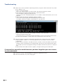
Click “start” ➔“All Programs” ➔ “Accessories” ➔“Command Prompt” in order.
2.After launching the command prompt enter a command “PING”.
Entry example C:\>ping XXX.XXX.XXX.XXX
“XXX.XXX.XXX.XXX” should be entered with an IP address to be connected to, such as the
projector.
3.When connecting normally, the display will be as follows.
(The screen may be slightly different depending on the OS type.)
<Example> when the IP address connected to is “192.168.150.1”
4.When a command cannot be sent, “Request time out” will be displayed.
Check the network setting again.
If communication can still not be established properly, contact your network administrator.
5.To return to the Windows® screen, enter “exit” and then press the “Enter” key.
¥ When the projector cannot be connected, even though the “PING” command is checked:
1.When “Accept IP Address” is set on the projector, set the IP address of the PC to be
connected.
2.When a security software is installed on the PC, or when a fire wall has been set up for the
network system, connection may not be possible. Consult the system administrator when,
for example, you want to change the settings to enable use of the TCP port set as the data
port.
3.When neither of the above two items applies, change the settings for the data port.
A connection cannot be made because you have forgotten your user name
or your password.
¥ Initialize the settings. (See page 62 of the projector's operation manual.)
¥ After the initialization, carry out setting again.
-26