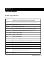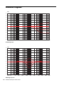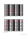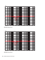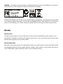
1
M-Audio Studiophile DSM3 Active Studio Monitors English User Guide ! CAUTION RISK OF ELECTRIC SHOCK DO NOT OPEN CAUTION: TO REDUCE THE RISK OF ELECTRIC SHOCK, DO NOT REMOVE COVER (OR BACK). NO USERSERVICABLE PARTS INSIDE. REFER SERVICING TO QUALIFIED SERVICE PERSONNEL ! ATTENTION: RISQUE DE CHOC ELECTRIQUE N’OUVRIR PAS AFIN DEVITER UN CHOC ELECTRIQUE ET LES CONSEQUENCES GRAVES QUI POURRAIENT ENRESULTER, TENTEZ PAS D’OUVRIR L’APPAREIL ET DE TOUCHER AUX COMPOSANTS INTERNES SANS LA PRESENCE D’UNE PERSONNE QUALIFIEE. ! PRECAUCION: RIESGO DE ELECTROCHOQUE NO ABRIR LA TAPA PARA REDUCIREL RIESGO DE SACUDIDAS ELECTRICAS, NO DEBERA QUITARSE LA TAPA (NI PARTE POSTERIOR). CONSULTESE AL PERSONAL CAPACITADO PARA LAS REPARACIONES INTERNAS WARNING: TO PREVENT FIRE OR ELECTRIC SHOCK, DO NOT EXPOSE THIS APPLIANCE TO RAIN OR MOISTURE. ADVERTENICIA: PARA EVITAR EL RIESGO DE INCENDIO O SACUDIDA ELECTRICA, NO DEBERA EXPONERSE ESTE APARATO A LA LLUVIA O HUMEDAD. CAUTION: TO PREVENT ELECTRIC SHOCK DO NOT USE THIS (POLARIZED) PLUG WITH AN EXTENSION CORD, RECEPTACLE OR OTHER OUTLET UNLESS THE BLADES CAN BE FULLY INSERTED TO PREVENT BLADE EXPOSURE. ATTENTION: POUR PREVENIR LES CHOCS ELECTRIQUES NE PAS UTILISER CETTE FICHE POLARISEE AVEC UN PROLONGATEUR. UNE PRISE DE COURANT OU UNE AUTRE SORTIE DE COURANT, SAUF SILES LAMES PEUVENT ETRE INSEREES A FOND SANS EN LAISSER AUCUNE PARTIE FOND SANS EN LAISSERAUCUNE PARTIE A DECOUVERT. PRECAUCION: PARA EVITAR SACUDIDAS ELECTRICAS, NO DEBERA UTILIZARSE ESTA CLAVIJA POLARIZADA CON UN CORDON DE PROLONGACION, RECEPTACULO U OTRO TIPO DE SALIDA A MENOS QUE SE HAYAN INSERTASO COMPLETAMENTE LAS LENGÜETAS PARA EVITAR SU EXPOSICION. NOTE: Some products are equipped with dual or multi-voltage transformers (which is indicated on the back panel). If you wish to change the voltage, please bring your unit to an authorized service technician for internal conversion. ATTENTION: Quelques piéces sont munies de transformateurs á double ou á multi-voltage (indiqué au panneau arriére). Si vous voulez changer le voltage, veuillez apporter votre appareil au fournisseur de pour le transformer. ZUR BEACHTUNG: Einige Geräte sind mit Umschaltern für unterschiedliche Netzspannungen ausgerüstet (ein Vermerk auf der Rückseite weist darauf hin). Die Anpassung, wenn notwendig, muß von einem qualifizieren Techniker in einer Servicestation vorgenommen werden. NOTA: Ciertos componentes de están dotados de transformadores de doble tensión o de varias tensiones (Io que se indica en el panel posterior). Si se desea cambiar la tensión, sírvanse llevar el aparato a un técnico autorizado por para su conversión interna. NOTE TO CATV SYSTEMS INSTALLER: This reminder is provided to call the CATV system installer’s attention to Article 820-22 of the NEC that provides guidelines for proper grounding and, in particular, specifies that the cable ground shall be connected to the grounding system of the building, as close to the point of cable entry as practical. NOTA PARA EL INSTALADOR DE ANTENAS DE TELEVISION COLECTIVAS: La presente advertencia se provee para llamar la atención del instalador al Artículo 820-22 de NEC (Córdigo Eléctrico Nacional) donde se facilitan las directrices para la pertinente puesta a tierra y que especifica en particular que el condutor a tierra del cable debe connectarse al sistema de conexión a tierra del edificio, lo más proximo posible al punto de entrada del cable. The lightning flash with arrowhead, within an equilateral triangle, is intended to alert the user of the presence of uninsulated “dangerous voltage” within the product’s enclosure; that may be of sufficient magnitude to constitute a risk of electric shock to persons. ! The exclamation point within an equilateral triangle is intended to alert the user of the presence of important operating and maintenance (servicing) instructions in the literature accompanying the appliance. Warning: This speaker shall not be placed in a closed area during operation so that the main switch can be easily accessed by the user. Important Safety Instructions 1. READ INSTRUCTIONS 9. HEAT All the safety and operating instructions should be read before the appliance is operated. Do not install near any heat sources such as radiators, heat registers, stoves, or other apparatus (including amplifiers) that produce heat. 2. RETAIN INSTRUCTIONS The safety and operating instructions should be retained for future reference. 10. CLEANING 3. HEED WARNINGS 11. POWER SOURCES All warning on the appliance and in the operating instructions should be adhered to. The appliance should be connected to a power supply only of the type described in the operating instructions or as marked on the appliance. 4. FOLLOW INSTRUCTIONS All operating and use instructions should be followed. The appliance should be cleaned only with dry cloth. 12. POWER CORD PROTECTION The appliance should not be used near water – for example, near a bathtub, washbowl, kitchen sink, laundry tub, in a wet basement, or near a swimming pool, etc. Power-supply cord should be routed so that they are not likely to be walked on or pinched by items placed upon or against them, playing particular attention to cords at plugs, convenience receptacles, and the point where they exit from the appliance. 6. CARTS AND STANDS 13. POLARIZED PLUG The appliance should be used only with a cart or stand that is recommended by the manufacturer. Do not defeat the safety purpose of the polarized or groundingtype plug. A polarized plug has two blades with one wider than the other. A grounding type plug has two blades and a third grounding prong. The wide blade or the third prong are provided for your safety. When the provided plug does not fit into your outlet, consult an electrician for replacement of the obsolete outlet. 5. WATER AND MOISTURE 6A. An appliance and cart combination should be moved with care. Quick stops, excessive force, and uneven surfaces may cause the appliance and cart combination to overturn. 14. UNPLUG POWER CORD 7. WALL OR CEILING MOUNTING Unplug this apparatus during lightning storms or when unused for long periods of time. This equipment is not designed for use mounted on a wall or a ceiling. 15. OBJECT AND LIQUID ENTRY 8. VENTILATION No object filled with liquids, such as vases, etc. shall be placed on the apparatus. The appliance should be situated so that its location or position does not interfere with its proper ventilation. For example, the appliance should not be situated on a bed, sofa, rug, or similar surface that may block the ventilation openings, or places in a built-in installation, such as bookcase or cabinet that may impede the flow of air through the ventilation openings. At least 30 cm free space around the unit for normal ventilation is required. 16. ACCESSORIES Only use attachments/accessories specified by the manufacturer. 17. SERVICING The user should not attempt to service the appliance beyond that described in the operating instructions. All other servicing should be referred to qualified service personnel. 18. DAMAGE REQUIRING SERVICE The appliance should be serviced by qualified service personnel when: a) The power-supply cord or the plug has been damaged; or b) Objects have fallen, or liquid has been spilled into the appliance; or c) The appliance has been exposed to rain; or d) The appliance does not appear to operate normally or exhibits a marked change in performance; or e) The appliance has been dropped, or the enclosure is damaged. contents Chapter 1. Introduction . . . . . . . . . . . . . . . . . . . . . . . . . . . . . . . . . . . . . . . . . . . . . . . . . . . . . . 1 What’s in the Box? . . . . . . . . . . . . . . . . . . . . . . . . . . . . . . . . . . . . . . . . . . . . . . . . . . . . . . . 1 Features. . . . . . . . . . . . . . . . . . . . . . . . . . . . . . . . . . . . . . . . . . . . . . . . . . . . . . . . . . . . . . . 1 About the Speakers. . . . . . . . . . . . . . . . . . . . . . . . . . . . . . . . . . . . . . . . . . . . . . . . . . . . . . . 1 Chapter 2. Overview of the DSM3 Speaker . . . . . . . . . . . . . . . . . . . . . . . . . . . . . . . . . . . . . 3 Back Panel Connectors and Controls. . . . . . . . . . . . . . . . . . . . . . . . . . . . . . . . . . . . . . . . . . . 3 Front Panel. . . . . . . . . . . . . . . . . . . . . . . . . . . . . . . . . . . . . . . . . . . . . . . . . . . . . . . . . . . . . 6 Chapter 3. Setup and Operation . . . . . . . . . . . . . . . . . . . . . . . . . . . . . . . . . . . . . . . . . . . . . . . 7 Getting Started . . . . . . . . . . . . . . . . . . . . . . . . . . . . . . . . . . . . . . . . . . . . . . . . . . . . . . . . . . 7 Setting Up the Speakers . . . . . . . . . . . . . . . . . . . . . . . . . . . . . . . . . . . . . . . . . . . . . . . . . . . 7 Configuring and Connecting AC Power. . . . . . . . . . . . . . . . . . . . . . . . . . . . . . . . . . . . . . . . . . 9 Power Up and Power Down . . . . . . . . . . . . . . . . . . . . . . . . . . . . . . . . . . . . . . . . . . . . . . . . 10 Connecting Audio . . . . . . . . . . . . . . . . . . . . . . . . . . . . . . . . . . . . . . . . . . . . . . . . . . . . . . . 11 Configuring Speaker Settings . . . . . . . . . . . . . . . . . . . . . . . . . . . . . . . . . . . . . . . . . . . . . . . 13 Tips for Best Performance . . . . . . . . . . . . . . . . . . . . . . . . . . . . . . . . . . . . . . . . . . . . . . . . . 16 Troubleshooting . . . . . . . . . . . . . . . . . . . . . . . . . . . . . . . . . . . . . . . . . . . . . . . . . . . . . . . . 16 Appendix A. Specifications . . . . . . . . . . . . . . . . . . . . . . . . . . . . . . . . . . . . . . . . . . . . . . . . . . 17 Technical Specifications. . . . . . . . . . . . . . . . . . . . . . . . . . . . . . . . . . . . . . . . . . . . . . . . . . . 17 Reference Diagrams . . . . . . . . . . . . . . . . . . . . . . . . . . . . . . . . . . . . . . . . . . . . . . . . . . . . . 18 Contents v vi M-Audio Studiophile DSM3 Guide chapter 1 Introduction Thank you for choosing M-Audio® Studiophile® DSM active reference speakers. Features This guide provides installation and operation instructions for the M-Audio DSM3 speaker. DSM3 speakers have the following features: DSM3 speakers feature high-end design elements and precision control circuitry, engineered to provide exceptional tonal accuracy, clarity and dynamic range in a wide variety of applications. • Selectable analog and digital inputs What’s in the Box? • One DSM3 speaker • One AC power cable • Four acoustic isolation pads • Self-powered, bi-amplified operation • Custom-tuned enclosures • Advanced driver design and materials • Onboard DSP for crossover control, EQ, and volume trim About the Speakers Amplifiers M-Audio DSM3 speakers feature built-in amplifiers. Bi-Amplification DSM3 HF and LF drivers are independently powered by two separate, low-distortion internal power amplifiers. Class D Design DSM3 Class D amplifiers combine the efficiency and size advantages of a digital amplifier with the precision, control and sound quality of linear amplification. Chapter 1: Introduction 1 Inputs Drivers M-Audio DSM3 speakers allow analog or digital inputs. Input type is selectable with the Input Select switch on the back panel of the speaker. Each input type has two available connectors. LF Drivers DSM3 speakers have two 6.5-inch LF drivers with a steel frame and single-piece anodized aluminum diaphragm. Dual LF drivers increase the width of the listening sweet spot and reduce early reflections from hard surfaces in the control room. Analog Inputs The analog input signal is sampled on input and processed digitally until it reaches the power amplifier stage. Available analog inputs include balanced XLR and 1/4-inch TRS connectors. These analog inputs are summed so that both input connectors may be used at the same time. Digital Inputs The digital inputs automatically detect the sample rate and bit depth of the input, and accept up to 192kHz/24-bit signals. Available digital inputs include AES/EBU and S/PDIF connectors. Only one digital connector may be used at a time. Enclosure 2 HF Driver DSM3 speakers have a 1-inch HF driver with a soft-dome ferro-fluid cooled design that ensures smooth, accurate reproduction of highfrequency details. Digital Signal Processing DSM3 speakers employ 36-bit digital signal processing for control of crossover, EQ, and channel assignment settings. Crossover The crossover function is handled by a digital processor that ensures flat, distortionfree integration of the LF and HF drivers. DSM3 speakers feature a high-efficiency, reinforced medium-density fiberboard enclosure. EQ and Placement Settings Six filters allow for customization of speaker response to a variety of sonic conditions and speaker orientations in your studio. Custom Waveguides The front panel waveguides are designed to maintain accurate frequency response and stereo imaging. Digital Channel Assignment When working with digital input, this switch is used to select the channel to be monitored in the speaker. Bass Reflex Port A dual-flange bass reflex port provides enhanced low frequency response and clarity, while minimizing extraneous noise and vibration. Volume Trim The Volume Trim control adjusts level of the input signal in the digital domain. M-Audio Studiophile DSM3 Guide chapter 2 Overview of the DSM3 Speaker This chapter describes the connectors, controls and features of the DSM3 speaker. Back Panel Connectors and Controls Analog Input (XLR) Analog Input (TRS) Bass Reflex Port Analog Input Sensitivity switch Digital Input (S/PDIF) Digital Thru (S/PDIF) Digital Input (AES/EBU) Volume Trim knob Digital Channel Assignment switch Input Selector switch EQ Setting switches Voltage selector Power switch AC connector Fuse holder Figure 1. Back panel of the DSM3 Chapter 2: Overview of the DSM3 Speaker 3 Power Connections AC Connector and Power Switch The AC connector accepts a standard modular AC power cord. One power cord is included with your speaker. Use the Power switch to turn the speaker on or off. Digital Standby Activates the digital inputs of the speaker, but automatically puts the speaker in a low-power standby mode when the digital clock signal is lost for more than one second (for example, when the digital source is powered off). When the clock signal is restored, the speaker wakes up from standby mode. Analog Inputs Voltage Selector Before connecting a DSM3 speaker to a power source, make sure the Voltage Selector setting matches your local voltage (100–120V or 220–240V). Fuse The fuse protects components of the DSM3 speaker from being damaged by electrical underor over-powering, spikes, and other anomalies. A 2.5 Amp fuse is required for both the 100–120V and the 220–240V settings. Make sure to use a fuse rated at 2.5 Amps. Do not use fuses of any other rating, or you risk damage to the unit The DSM3 speaker provides an XLR analog input connector and a balanced 1/4-inch TRS analog input connector. The analog input signal is converted to a 96 kHz, 24-bit digital signal for crossover/EQ processing, and converted back to analog just prior to the power stage of the driver amplifiers. Signals may be sent to the two analog input connectors at the same time. When two analog input signals are present, they are summed. XLR Connector The XLR Analog In connector is balanced. (If the signal source is unbalanced, connect the unused pin to ground.) Inputs 1/4-inch TRS Connector Input Selector Switch The 1/4-inch TRS Analog In connector is balanced. (If the signal source is unbalanced, connect the unused pin to ground.) The input selector switch selects between the following input states for the speaker: Analog Input Sensitivity Switch Analog Activates the analog inputs of the speaker. Digital Activates the digital inputs of the speaker. 4 M-Audio Studiophile DSM3 Guide The analog input operating level can be switched between –10 dBV and +4 dBu. This setting applies to both the XLR and 1/4-inch TRS analog inputs. For information on the appropriate operating level for your audio source, see the manufacturer’s specifications. Digital Inputs EQ Settings The DSM3 speaker provides an AES/EBU Digital In connector as well as S/PDIF Digital In and S/PDIF Digital Thru connectors. The DSM3 speaker has a series of 12 switches for setting the following EQ controls: The digital inputs accept sample rates of 44.1, 48, 88.2, 96, 176.4 and 192 kHz (+/– 10 percent) at 16-bit or 24-bit resolution. Only one digital input connector (AES/EBU In or S/PDIF In) may be used at a time. AES/EBU Digital In The AES/EBU digital input is a female XLR connector. S/PDIF Digital In This S/PDIF connector is for connecting digital audio from a S/PDIF source device, or from the S/PDIF Thru connector of another DSM3 speaker. S/PDIF Digital Thru This S/PDIF connector passes digital input from either the AES/EBU Digital In or the S/PDIF Digital In connector to the S/PDIF Digital In connector of another DSM3 speaker. Digital Channel Assigment The DSM3 speaker has a digital channel assignment switch that lets you monitor the left channel, right channel, or a summed (mono) mix of the left and right channels of the digital input. Volume Trim Control High-Frequency Shelf Sets an adjustable high frequency boost or cut using a built-in HF shelftype EQ. Mid-Range EQ Sets an adjustable midrange frequency boost or cut using a built-in peak/notchtype EQ. Low-Frequency Shelf Sets a low frequency cut using a built-in LF shelf-type EQ, which lets you tune the speaker’s bass response to fit your monitoring environment. High-Pass Filter Sets a high-pass type EQ, which lets you establish the lower limit of the speaker’s frequency response. Desktop 220 Hz Cuts around a center frequency of 220 Hz using a built-in notch-type EQ, which lets you compensate for the effects of frequency buildup when your DSM3 speaker is placed on a reflective surface. Desktop 175 Hz Cuts around a center frequency of 175 Hz using a built-in notch-type EQ, which lets you compensate for the effects of frequency buildup when your DSM3 speaker is placed on a reflective surface. Desktop 200 Hz By using both the Desktop 220 Hz and the Desktop 175 Hz settings, you can cut around a center frequency of 200 Hz to compensate for the effects of frequency buildup when your DSM3 speaker is placed on a reflective surface. The Volume Trim control adjusts the level of the input signal in the digital domain. Trim values range from –22 dB to +10 dB. Chapter 2: Overview of the DSM3 Speaker 5 Front Panel LED indicator Front panel of the DSM3 Front Panel LED The LED indicator on the front of the DSM3 speaker indicates the following states: Front Panel LED States 6 LED State Indication Blue Analog Input Digital Input: Lock Yellow Digital Input: No Lock Blue (flashing) Digital Standby Mode Red Clipping Red (flashing) Hardware failure M-Audio Studiophile DSM3 Guide chapter 3 Setup and Operation This chapter provides instructions for placing, connecting and configuring DSM3 speakers. Setting Up the Speakers Correct placement, connection, and configuration ensures optimal performance and safe operation of your speakers. Speakers should always be placed to provide balanced, accurate sound in your preferred mixing position. The exact location depends on the size and acoustics of the environment where you are using the speakers. Getting Started In all installations, observe the following guidelines: Unpacking the Speakers After opening the box, be sure to reach down the sides of the speaker to lift it out of its box. This protects the HF and LF drivers on the front from being dented or punctured, and prevents any possible damage to the switches, connectors, and other controls on the back of each speaker. • Place the speakers on quality stands, or place them in a stable location where they are suitably isolated from vibration • Do not soffit mount or otherwise install the speakers in an enclosed space. The speakers require free air flow around the back panel. Do not restrict air flow around the speakers. Reusing the Speaker Packaging Retain your packaging for future use. The cartons are durable and reusable, and can be used to safely transport your speakers. Chapter 3: Setup and Operation 7 Speaker Orientation Speaker Location Vertical Orientation Make sure speakers are placed symmetrically in relation to the listening position by doing the following: The DSM3 yields the best sonic results in a vertical orientation. When placing the DSM3 vertically within a stereo setup, it is recommended to have the HF drivers pointing to the outside on both sides. With the HF drivers on the outside, a wider stereo image is produced when monitoring in nearfield conditions. To have the HF drivers on the outside, one of the DSM3 speakers must be placed upside down. DSM3 vertical orientation (stereo) Horizontal Orientation Due to the tight grouping of the three drivers on the DSM3, horizontal orientation can also yield excellent results. However, the listening window may be narrower with horizontal placement as compared with the vertical placement. When placing the DSM3 in a horizontal orientation, it is recommended to have the HF driver on the top to avoid interference from boundary reflections. DSM3 horizontal orientation (stereo) 8 M-Audio Studiophile DSM3 Guide Place speakers so that the HF drivers are approximately the same height as your ears in the mixing position. Place speaker pairs the same distance from the two sides of the room. Place speakers so that the backs of the speakers are a minimum of 6 inches (15 cm) from the wall to prevent obstruction of air flow in the bass ports. Stereo Positioning The following diagram shows the recommended setup for stereo monitoring. Configuring and Connecting AC Power Be sure to follow the instructions in this section for the proper configuration of fuses and voltage settings. DSM3 speakers must be manually configured for the voltage in your area. Always check the voltage setting and fuse rating, as described below, before connecting and powering your speakers. 0.5m/20" Setting the Voltage Make sure the Voltage Selector setting on each speaker matches your local voltage (100–120V or 220–240V). Stereo placement Surround Positioning The following diagram shows the recommended setup for use in a 5.0 surround environment (a subwoofer is not shown in this diagram). Voltage selector CENTER FRONT RIGHT FRONT LEFT Voltage selector o 25 o 30 o 30 o 100 o 135 o 25 WITHIN THIS WINDOW REAR LEFT REAR RIGHT Surround placement Chapter 3: Setup and Operation 9 Installing a Fuse Connecting Power A 2.5 Amp fuse is required for both the 100–120V and the 220–240V settings. To connect power to the speakers: 1 Make sure you have set the Voltage Selector Make sure to use a fuse rated at 2.5 Amps. Do not use fuses of any other rating, or you risk damage to the unit To change the fuse: 1 Turn off power to the speaker and disconnect the AC power cord. and installed the proper fuse before proceeding. (See “Setting the Voltage” on page 9 for details.) 2 Connect the included AC power cord to the AC connector on the back panel of each speaker (one power cord is included with each speaker). 2 Use a small screwdriver to remove the fuse holder. AC connector Fuse holder AC connector Fuse holder 3 Connect the other end of the AC power cord 3 Remove the currently installed fuse. to your power source. 4 Install the new fuse in the fuse holder. 5 Replace the fuse holder so that it clicks into place. Power Up and Power Down Always power up your speaker system last (allowing mixers, recorders and other devices to fully power up first). Conversely, always mute (or power off) your speaker system first, before powering off other devices in your studio. 10 M-Audio Studiophile DSM3 Guide Connecting Digital Inputs Connecting Audio This section explains how to make analog and digital audio connections to DSM3 speakers. S/PDIF Input Connecting Analog Inputs S/PDIF Thru AES/EBU Input Analog Input (XLR) Digital input section Analog Input (TRS) Input Sensitivity switch Analog input section To connect an analog source: 1 Do any of the following: • Connect a balanced XLR cable to the XLR In connector on the back panel of the speaker. • Connect a balanced 1/4-inch balanced TRS cable to the TRS In connector on the back panel of the speaker. If you need to connect an unbalanced analog source, see “Analog Inputs” on page 4. DSM3 speakers accept digital input at the AES/EBU Digital Input (XLR connector) and the S/PDIF Digital Input. Only one digital input connector (AES/EBU In or S/PDIF In) may be active at a time. If the speaker receives digital input from more than one digital connector, digital lock may not be achieved and noise or distortion may result. Connecting Digital Sources AES/EBU and S/PDIF digital protocols carry two channels of audio (left and right). If you are using a digital source, you can connect it to either the AES Digital In or the S/PDIF In of one of the DSM3 speakers. (It does not matter which speaker is connected to the source.) 2 Connect the other end of the cable to the an- alog audio source (for example, an analog output from your monitoring system). Chapter 3: Setup and Operation 11 The Digital Thru S/PDIF port on this speaker is then connected to the Digital In port on the other speaker to supply it with its digital audio input. S/PDIF Input S/PDIF Thru Digital Input (AES shown) To connect a digital source: 1 Do any of the following: • Connect an AES cable (XLR) to the AES/EBU In port on the back of a speaker. • Connect a S/PDIF digital cable to the S/PDIF In port on the back of a speaker. 2 Connect the other end of the cable to the digital audio source (for example, a digital output from an M-Audio interface). 3 Connect one end of a S/PDIF digital cable to the S/PDIF Thru port of the first speaker. 4 Connect the other end of the S/PDIF digital cable to the S/PDIF In port of the second speaker. 5 Set the back panel Channel Assign switch to In and Thru connections for digital input (AES source shown) L (Left) or R (Right) as appropriate for the location of each speaker. Digital Channel Assignment When using digital input, you must configure the Channel Assign switches on the back of each speaker to set whether that speaker plays the Left or Right signal channel, accordingly. Channel Assign switch Channel Assign switch 12 M-Audio Studiophile DSM3 Guide Configuring Speaker Settings Volume Trim Settings The Volume Trim control lets you match the input sensitivity of speaker to the source. If you are monitoring an analog input, make sure you have set the Analog Input Sensitivity switch to match the operating level of your input source (–10 dBV or +4 dBu). For information on the appropriate operating level for your audio source, see the manufacturer’s specifications. The maximum input levels for each sensitivity setting are shown below. EQ Settings The EQ controls on DSM3 speakers let you adjust the response of the speaker to match your monitoring environment and studio equipment. For EQ frequency graphs for each of these settings, see “Reference Diagrams” on page 18. Setting the High Frequency Shelf EQ The HF Shelf EQ lets you compensate for high frequency variations that may be created by source equipment or room acoustics. Start with the HF Shelf EQ setting “flat” (0 dB) as this provides the most natural high-frequency response. To adjust the HF Shelf EQ: Maximum input levels Analog Input Sensitivity setting Maximum Input level (full-scale output) –10 dBV 3 dBV +4 dBu 18 dBu The Volume Trim control adjusts the level of the input signal in the digital domain. Trim values range from –22 dB to +10 dB, in 0.5 dB steps. Set switches 1 and 2 to the positions shown below to activate the corresponding EQ levels. OFF OFF 1 2 ON OFF OFF ON Setting the Volume Trim control to 0 maximizes the Signal to Noise ratio. ON ON 0 dB +1.5 dB –1.5 dB –3.0 dB HF Shelf switches and settings Chapter 3: Setup and Operation 13 Setting the Mid-Range EQ Setting the LF Shelf EQ The Mid-Range EQ lets you compensate for midrange resonance or damping that may be created by speaker placement or room acoustics. It offers a low-Q (wide bandwidth) boost or cut. Start by leaving this switch in the “flat” (0 dB) position, then experiment with different settings to see if you like the results. Your choice for the LF Shelf setting depends on where you place the speakers within a room. To adjust the Mid-Range EQ: Set switches 3 and 4 to the positions shown below to activate the corresponding EQ levels. OFF OFF 3 4 ON OFF OFF ON ON ON Mid-Range EQ switches and settings 0 dB +1.5 dB –1.5 dB –3.0 dB 0 dB If you've mounted your DSM3 speakers on speaker stands away from walls and corners, set the LF Shelf to 0dB, which will give you the flattest near-field frequency response. –1.5 dB If you've mounted your DSM3 speakers near a wall, or on a reflective surface such as the meter bridge of your console, set the LF Shelf to –1.5 dB, which activates a shelving filter to reduce the low-frequency buildup. –3.0 dB If you've mounted your DSM3 speakers on stands in a corner, set the LF Shelf to –3.0 dB, which activates a shelving filter to reduce the low-frequency buildup. –4.5 dB If you've mounted your DSM3 speakers on a meter bridge (or other reflective surface), as well as in a corner, set the LF Shelf to –4.5 dB, which activates a shelving filter to reduce the low-frequency buildup. To adjust the LF Shelf EQ: Set switches 5 and 6 to the positions shown below to activate the corresponding EQ levels. OFF OFF 5 6 ON OFF OFF ON ON ON LF Shelf EQ switches and settings 14 M-Audio Studiophile DSM3 Guide 0 dB –1.5 dB –3.0 dB –4.5 dB Setting the High-Pass Filter The High Pass Filter lets you adjust the bass rolloff of your DSM3 speakers. Start with the filter all the way open (40 Hz setting) and only raise the cutoff frequency in order to protect the LF drivers at low frequencies, or to couple your DSM3 speakers with a subwoofer. To adjust the Desktop 220 Hz Filter: Set switches 9 and 10 to the positions shown below to activate the corresponding EQ levels. OFF OFF 9 10 ON OFF 0 dB –1.0 dB To adjust the High Pass Filter: OFF Set switches 7 and 8 to the positions shown below to activate the corresponding EQ levels. OFF OFF 7 8 ON OFF OFF ON ON ON ON ON ON 40 Hz –2.0 dB –3.0 dB Desktop 220 Hz Filter switches and settings 60 Hz 80 Hz 100 Hz High-Pass Filter switches and settings To adjust the Desktop 175 Hz Filter: Set switches 11 and 12 to the positions shown below to activate the corresponding EQ levels. OFF OFF 11 12 ON OFF 0 dB –1.0 dB Setting the Desktop Filters OFF The Desktop filters let you compensate for the effects of frequency buildup when your DSM3 speaker is placed on a reflective surface such as a desktop or meter bridge, or within a reflective surface such as a shelf or case. Experiment with the EQ options centered around 175 Hz, 200 Hz (by using the 175 Hz and 220 Hz filters at the same time), or 220 Hz. ON ON ON –2.0 dB –3.0 dB Desktop 175 Hz Filter switches and settings Chapter 3: Setup and Operation 15 To adjust the Desktop 200 Hz Filter: Set switches 9, 10 11 and 12 to the positions shown below to activate the corresponding EQ levels. 9 10 11 12 OFF OFF OFF OFF ON The LED located on the front of the unit indicates the following states of operation. Front Panel LED States 0 dB ON OFF Troubleshooting LED State Indication Blue Analog Input Digital Input: Lock Yellow Digital Input: No Lock Blue (flashing) Digital Standby Mode Red Clipping Red (flashing) Hardware failure –1.0 dB OFF OFF ON OFF –2.0 dB ON ON ON ON ON If the LED is lit solid blue and there is no sound, do the following: –3.0 dB Desktop 200 Hz Filter switches and settings Tips for Best Performance DSM3 speakers are built and tested to exacting standards with features to protect the units from failure under normal usage. Keep in mind the following: Overdriving the units for prolonged periods or not observing the warnings set out in this guide may result in failure. If distortion occurs, reduce the input level immediately. Both the HF and LF drivers are delicate and should not be touched. A damaged driver will adversely affect the performance of the speaker. As a precaution, always turn off the units before plugging or unplugging signal connections or switching source equipment. 16 M-Audio Studiophile DSM3 Guide Check that the unit is receiving an analog signal or valid digital signal. Check the temperature of the rear metal panel. If it is hot, turn the unit off for a minimum of five minutes to allow it to cool. When cool, turn the unit on and check for normal operation. If necessary, relocate the unit to ensure adequate ventilation. If the thermal shutdown activates a second time, contact M-Audio customer service. If the LED is unlit and there is no sound: Check fuse and power connection. If the fuse is intact and the power connection is good, but the LED remains unlit with no sound, contact M-Audio customer service. appendix a Specifications Technical Specifications DSM3 Specifications LF Driver (2) 6.5-inch inverted anodized aluminum cone woofers with cone edge reinforcement 35mm voice coil with symmetrical force motor and flux stabilization rings HF Driver 1-inch soft teteron dome tweeter with neodymium magnet and ferrofluid cooling Frequency Response 45 Hz–27 kHz +/–3 dB Crossover 2.7 kHz Linkwitz-Riley 24 dB/octave Max SPL @ 1 meter 111 dB maximum peak SPL @ 1m for 1 unit (117 dB maximum peak per pair) Input Sensitivity +4 dBu pink noise input with Trim level set to 0 dB yields 90 dB @ 1m LF power amplifier 100 W (1% THD into 6 Ohms) HF power amplifier 80 W (0.5% THD into 6 Ohms) THD+N <0.05% (10 W into 6 Ohms) Soft Limit feature Independent anti-clipping limiters: tweeter limited to 0.5% THD, woofer limited to 5% THD Power Requirements User selectable for 90–130V~ 50/60 Hz or 180–264V~ 50/60 Hz DSP 36-bit, 192 kHz processing Protection Over current, over temperature, turn-on/off transient, subsonic filter Analog Inputs XLR balanced (20 kOhms) and 1/4-inch TRS balanced (20kOhms) Digital Inputs S/PDIF In and Thru (75 Ohms) and AES/EBU (110 Ohms); built-in phase-lock loop (PLL) to reclock incoming bitstreams with low jitter (<250 psec p-p); 44.1, 48, 88.2, 96, 176.4, 192 kHz sample rates Indicator RGB LED Appendix A: Specifications 17 Reference Diagrams 6 dBV 5 4 3 2 1 0 -1 -2 -3 -4 -5 -6 10 Hz 20 50 100 200 500 1K 2K 5K 10K 20K 40K 50 100 200 500 1K 2K 5K 10K 20K 40K HF Shelf EQ levels 6 dBV 5 4 3 2 1 0 -1 -2 -3 -4 -5 -6 10 Hz 20 Mid-Range EQ levels 18 M-Audio Studiophile DSM3 Guide 6 dBV 5 4 3 2 1 0 -1 -2 -3 -4 -5 -6 10 Hz 20 50 100 200 500 1K 2K 5K 10K 20K 40K 50 100 200 500 1K 2K 5K 10K 20K 40K LF Shelf levels 5 dBV 0 -5 -10 -15 -20 -25 -30 -35 10 Hz 20 High-Pass Filter levels Appendix A: Specifications 19 6 dBV 5 4 3 2 1 0 -1 -2 -3 -4 -5 -6 10 Hz 20 50 100 200 500 1K 2K 5K 10K 20K 40K 100 200 500 1K 2K 5K 10K 20K 40K Desktop EQ (220 Hz) levels 6 dBV 5 4 3 2 1 0 -1 -2 -3 -4 -5 -6 10 Hz 20 50 Desktop EQ (175 Hz) levels 20 M-Audio Studiophile DSM3 Guide 6 dBV 5 4 3 2 1 0 -1 -2 -3 -4 -5 -6 10 Hz 20 50 100 200 500 1K 2K 5K 10K 20K 40K Desktop EQ (200 Hz) levels Appendix A: Specifications 21 22 M-Audio Studiophile DSM3 Guide WARNING: This product contains chemicals, including lead, known to the State of California to cause cancer, and birth defects or other reproductive harm. Wash hands after handling. © 2008 Avid Technology, Inc. All rights reserved. Product features, specifications, system requirements and availability are subject to change without notice. Avid, M-Audio and Studiophile DSM are either trademarks or registered trademarks of Avid Technology, Inc. All other trademarks contained herein are the property of their respective owners. Warranty Warranty Terms M-Audio warrants products to be free from defects in materials and workmanship, under normal use and provided that the product is owned by the original, registered user. Visit www.m-audio.com/warranty for terms and limitations applying to your specific product. Warranty Registration Immediately registering your new M-Audio product entitles you to full warranty coverage and helps M-Audio develop and manufacture the finest quality products available. Register online at www.m-audio.com/register to receive FREE product updates and for the chance to win M-Audio giveaways. ML07-244A0_DSM3_UG_EN_08/08