1
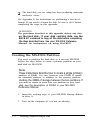
Attention Apex™ Owners
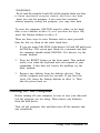
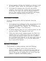
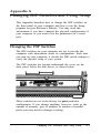
The MGA card in your computer includes a game port, such as
the one shown below. You can easily connect a joystick, track
ball, or other pointing device to this port.
Apex is a trademark of Epson America, Inc.
Copyright © 1989 by Epson America, inc.
Torrance, California
QA50189001
IMPORTANT SAFETY INSTRUCTIONS
1. Read all of these instructions and save them for lacer reference.
2. Follow all warnings and instructions marked on the product.
3. Unplug this product from the wall outlet before cleaning. Do not
use liquid cleaners or aerosol cleaners. Use a damp cloth for
cleaning.
4. Do not use this product near water.
5. Do not place this product on an unstable cart, stand, or table.
The product may fall, causing serious damage to the product.
6. Slots and openings in the cabinet and the back or bottom are
provided for ventilation; to ensure reliable operation of the
product and to protect it from overheating, these openings must
not be blocked or covered. The openings should never be
blocked by placing the product on a bed, sofa, rug, or other
similar surface. This product should never he placed near or over
a radiator or heat register. This product should not be placed in a
built in installation unless proper ventilation is provided
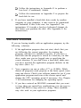
7. This product should he operated from the type of power source
indicated on the marking label. If you are not sure of the type of
power available, consult your dealer or local power company.
8. This product is equipped with a 3-wire grounding-type plug, a
plug having a third (grounding) pin. This plug will only fit into a
grounding type power outlet. This is a safety feature. If you are
unable to insert the plug into the outlet, contact your electrician
to replace your obsolete outlet. Do not defeat the purpose of the
grounding type plug.
9. Do not locate this product where the cord will be walked on.
10. If an extension cord is used with this product, make sure that the
total of the ampere ratings on the products plugged into the
extension cord Jo not exceed the extension cord ampere rating.
Also, make sure that the total of all products plugged into the
wall outlet does not exceed 15 amperes.
11. Never push objects of any kind into this product through cabinet
slots, as they may touch dangerous voltage points or short out
parts that could result in a risk of fire or electric shock. Never
spill liquid of any kind on the product.
12. Except as specifically explained in the User’s Manual, do not
attempt to service this product yourself. Opening or removing
those covers that are marked "Do Not Remove" may expose you
to dangerous voltage points or other risks. Refer all servicing in
those compartments to service personnel.
13. Unplug this product from the wall outlet and refer servicing to
qualified service personnel under the following conditions:
A. When the power cord or plug is damaged or frayed.
B. If liquid has ken spilled into the product.
C. If the product has ken exposed to rain or water.
D. If the product does not operate normally when the operating
instructions are followed. Adjust only those controls that
are covered by the operating instructions, since improper
adjustment of other controls may result in damage and will
often require extensive work by a qualified technician to
restore the product to normal operation.
E. If the product has ken dropped or the cabinet has been
damaged.
F. If the product exhibits a distinct change in performance,
indicating a need for service.
IMPORTANT NOTICE
DISCLAIMER OF WARRANTY
Epson America makes no representations or warranties, either express or
implied, by or with respect to anything in this manual, and shall not be
liable for any implied warranties of merchantability and fitness for a
particular purpose or for any indirect, special, or consequential damages.
Some states do not allow the exclusion of incidental or consequential
damages, so this exclusion may not apply to you.
COPYRIGHT NOTICE
All rights reserved. No part of this publication may be reproduced, stored
in a retrieval system, or transmitted, in any form or by any means,
electtonic, mechanical, photocopying, recording, or otherwise, without the
prior written permission of Epson America, inc. No patent liability is
assumed with respect to the use of information contained herein. While
every precaution has been taken in the preparation of this publication,
Epson America assumes no responsibility for errors or omissions. Nor is any
liability assumed for damages resulting from the use of the information
contained herein. Further, this publication and the features described herein
are subject to change without notice.
TRADEMARKS
ActionPrinter and Apex are trademarks of Epson America, Inc.
Epson is a registered trademark of Seiko Epson Corporation.
Hercules is a registered trademark of Hercules Computer Technology, Corp.
IBM is a registered trademark of International Business Machines Corp.
MS-DOS and Microsoft are registered trademarks of Microsoft Corp.
XTREE is a registered trademark of Executive Systems, inc.
Copyright © 1989 by Epson America, Inc.
Torrance, California
ii
Y14499103200
FCC COMPLIANCE STATEMENT FOR AMERICAN USERS
This equipment generates and uses radio frequency energy and if not installed and
used properly, hat is, in strict accordance with the manufacturer’s instructions, may
cause interference co radio and television reception. It has been type tested and
found co comply with the limits for a Class B computing device in accordance with
the specifications in Subpart J of Part 15 of FCC Rules, which are designed co
provide reasonable protection against such interference in a residential installation.
However, there is no guarantee that interference will not occur in a particular
installation. If this equipment does cause interference to radio and television
reception, which can be determined by turning the equipment off and on, you are
encouraged co try co correct the interference by one or more of the following
measures:
l
Reorient the receiving antenna
l
Relocate the computer with respect to the receiver
l
Move the computer away from the receiver
l
Plug the computer into a different outlet so chat the computer and receiver are
on different branch circuits.
If necessary, consult your dealer or an experienced radio/television technician for
additional suggestions. You may find the following booklet prepared by the Federal
Communications Commission helpful:
“Television Interference Handbook.”
This booklet is available from the U.S. Government Printing Office, Washington,
DC 20402. Stock No. 004-000-00450-7.
Note: If the interference stops, it was probably caused by the computer or its
peripheral devices. To further isolate the problem: Disconnect the peripheral devices
and their input/output cables one at a time. If the interference stops, it is caused by
either the peripheral device or its I/O cable. These devices usually require shielded
I/O cables. For Epson peripheral devices, you can obtain the proper shielded cable
from your dealer. For non-Epson peripheral devices contact the manufacturer or
dealer for assistance.
WARNING: This equipment has been certified to comply with the limits for a
Class B computing device, pursuant to Subpart J of Part 15 of FCC Rules. Only
peripherals (computer input/output devices, terminals, printers, etc.) certified co
comply with the Class B limits may be attached to this computer. Operation with
non-certified peripherals is likely to result in interference to radio and TV
reception. The connection of a non-shielded equipment interface cable to this
equipment will invalidate the FCC Certification of this device and may cause
interference levels that exceed the limits established by the FCC for this
equipment.
This digital apparatus does not exceed the Class A/ Class B (whichever is applicable)
limits for radio noise emissions from digital apparatus as set out in the radio
interference regulations of the Canadian Department of Communications.
Le présent appareil numérique n'émet pas de bruits radioélectriques dépassant la
limites applicables aux appareils numériques de Classe A/de Classe B (selon le cas)
prescrites dans le règlement sur le brouillage radioélectriques édicté par le Ministère
des Communications du Canada.
iii
Contents
Introduction.. . . . . . . . . . . . . . . . . . . . . . . . . . . . . . . . . . . . . .
How to Use This Manual . . . . . . . . . . . . . . . . . . . . . . . . . . . . .
Where to Get Help . . . . . . . . . . . . . . . . . . . . . . . . . . . . . . . . . .
Chapter 1
Setting Up Your System
1 Unpacking . . . . . . . . . . . . . . . . . . . . . . . . . . . . . . . . . . . . . . .
Removing the Diskette Drive Protector Card . . . . . . . . .
2 Choosing a Location . . . . . . . . . . . . . . . . . . . . . . . . . . . . . . .
3 Connecting a Monitor . . . . . . . . . . . . . . . . . . . . . . . . . . . . .
4 Connecting a Peripheral Device. . . . . . . . . . . . . . . . . . . . . .
Using the Parallel Interface . . . . . . . . . . . . . . . . . . . . . . .
Using the Serial interface. . . . . . . . . . . . . . . . . . . . . . . . .
5 Connecting the Power Cord . . . . . . . . . . . . . . . . . . . . . . .
6 connecting the Keyboard . . . . . . . . . . . . . . . . . . . . . . . . . . .
Adjusting the Keyboard Angle. . . . . . . . . . . . . . . . . . . . .
7 Turning On the Computer . . . . . . . . . . . . . . . . . . . . . . . . . .
8 Loading MS-DOS . . . . . . . . . . . . . . . . . . . . . . . . . . . . . . . . .
Loading MS-DOS On the Apex 100 . . . . . . . . . . . . . . . .
The Command Prompt . . . . . . . . . . . . . . . . . . . . . . . . . . .
Setting the Time and Date on the Apex 100\20 . . . .
9 Copying System Diskettes . . . . . . . . . . . . . . . . . . . . . . . . .
Copying Diskettes on the Apex 100 . . . . . . . . . . . . . . . .
Copying Diskettes on the Apex 100\20 . . . . . . . . . . . . .
Chapter 2
1
2
3
1-1
1-2
1-3
1-4
1-7
1-7
1-9
1-10
1-11
1- 13
1-14
1-15
1-16
1-18
1-19
1-21
1-21
1-23
Using Your Computer
Changing the Operating Speed . . . . . . . . . . . . . . . . . . . . . . . .
Using Special Keys . . . . . . . . . . . . . . . . . . . . . . . . . . . . . . . . . .
Stopping a Command or Program . . . . . . . . . . . . . . . . . . . . .
Resetting the Computer . . . . . . . . . . . . . . . . . . . . . . . . . . . . . .
Turning Off the Computer . . . . . . . . . . . . . . . . . . . . . . . . .
2-1
2-2
2-4
2-4
2-5
Contents v
Using Disks and Disk Drives. . . . . . . . . . . . . . . . . . . . . . . . . . .
How Disks Store Data . . . . . . . . . . . . . . . . . . . . . . . . . . .
Choosing Diskettes. . . . . . . . . . . . . . . . . . . . . . . . . . . . . .
Caring for Diskettes and Diskette Drives . . . . . . . . . . . . .
Inserting and Removing Diskettes . . . . . . . . . . . . . . . . . .
Write-protecting Diskettes . . . . . . . . . . . . . . . . . . . . . . . .
Making Backup Copies . . . . . . . . . . . . . . . . . . . . . . . . . . .
Using a Single Diskette Drive . . . . . . . . . . . . . . . . . . . . .
Using the Hard Disk Drive . . . . . . . . . . . . . . . . . . . . . . . .
Chapter 3
2-6
2-6
2-8
2-9
2-11
2-13
2-14
2-15
2-16
Using MS-DOS With Your Computer
Starting and Exiting MS-DOS . . . . . . . . . . . . . . . . . . . . . . . . .
Starting An Application Program. . . . . . . . . . . . . . . . . . . . . . .
Using Drive Designators . . . . . . . . . . . . . . . . . . . . . . . . . . . . . . .
The Default Drive. . . . . . . . . . . . . . . . . . . . . . . . . . . . . . .
Types of MS-DOS Commands . . . . . . . . . . . . . . . . . . . . . . . . .
Entering an MS-DOS Command . . . . . . . . . . . . . . . . . . . . . . .
Creating and Managing Files . . . . . . . . . . . . . . . . . . . . . . . . . .
Naming Files. . . . . . . . . . . . . . . . . . . . . . . . . . . . . . . . . . .
Copying Files . . . . . . . . . . . . . . . . . . . . . . . . . . . . . . . . . .
Renaming Files . . . . . . . . . . . . . . . . . . . . . . . . . . . . . . . . .
Deleting Files . . . . . . . . . . . . . . . . . . . . . . . . . . . . . . . . . .
Printing Files. . . . . . . . . . . . . . . . . . . . . . . . . . . . . . . . . . .
Using Directories. . . . . . . . . . . . . . . . . . . . . . . . . . . . . . . . . . . .
The Default Directory . . . . . . . . . . . . . . . . . . . . . . . . . . . .
Changing the Default Directory . . . . . . . . . . . . . . . . . . . .
Using Pathnames . . . . . . . . . . . . . . . . . . . . . . . . . . . . . . .
Including Filenames With Pathnames . . . . . . . . . . . . . . .
Including Drive Letters With Pathnames
and Filenames . . . . . . . . . . . . . . . . . . . . . . . . . . . . . . .
Creating Directories . . . . . . . . . . . . . . . . . . . . . . . . . . . . .
Listing the Contents of a Directory . . . . . . . . . . . . . . . . .
Displaying a List of Directories. . . . . . . . . . . . . . . . . . . . .
Removing Directories. . . . . . . . . . . . . . . . . . . . . . . . . . . .
vi Contents
3-2
3-2
3-3
3-3
3-4
3-6
3-8
3-9
3-10
3-12
3-13
3-14
3-15
3-17
3-17
3-18
3-19
3-19
3-21
3-22
3-23
3-24
Formatting Diskettes . . . . . . . . . . . . . . . . . . . . . . . . . . . . . . . . .
Formatting Diskettes on the Apex 100 . . . . . . . . . . . . . .
Formatting Diskettes on the Apex 100\20 . . . . . . . . . . .
Formatting Diskettes With One Diskette Drive
(No Hard Disk) . . . . . . . . . . . . . . . . . . . . . . . . . . . . .
Backing Up Data . . . . . . . . . . . . . . . . . . . . . . . . . . . . . . . . . . . .
Using the DISKCOPY Command . . . . . . . . . . . . . . . . . .
Using the BACKUP Command. . . . . . . . . . . . . . . . . . . .
Special Epson Utilities . . . . . . . . . . . . . . . . . . . . . . .
Using HELP . . . . . . . . . . . . . . . . . . . . . . . . . . . . . . . . . . .
Using MENU . . . . . . . . . . . . . . . . . . . . . . . . . . . . . . . . . .
usingxTREE . . . . . . . . . . . . . . . . . . . . . . . . . . . . . . . . . . .
3-25
3-26
3-27
3-28
3-29
3-29
3-33
3-34
3-34
3-36
3-39
Using an AUTOEXEC.BAT File . . . . . . . . . . . . . . . . . . . . . . . 3-43
Creating an AUTOEXEC.BAT File . . . . . . . . . . . . . . . . 3-44
Using HDCACHE for the Hard Disk. . . . . . . . . . . . . . . . . . . . 3-45
Chapter 4
Installing Option Cards
Removing the Cover. . . . . . . . . . . . . . . . . . . . . . . . . . . . . . . . .
Inserting an Option Card . . . . . . . . . . . . . . . . . . . . . . . . . . . . .
Removing an Access Slot Cover . . . . . . . . . . . . . . . . . . .
Removing an Option Card . . . . . . . . . . . . . . . . . . . . . . . . . . . .
Replacing the Cover . . . . . . . . . . . . . . . . . . . . . . . . . . . . . . . . .
Post-installation Setup . . . . . . . . . . . . . . . . . . . . . . . . . . . . . . .
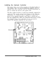
Optional Disk Drive Controllers . . . . . . . . . . . . . . . . . . . . . . .
Installing the Optional Controller . . . . . . . . . . . . . . . . . .
Changing the Jumper Setting. . . . . . . . . . . . . . . . . . . . . .
Chapter 5
4-2
4-4
4-7
4-8
4-8
4-9
4-10
4-11
4-12
Troubleshooting
The Computer Won’t Start . . . . . . . . . . . . . . . . . . . . . . . . . . .
The Computer Locks Up . . . . . . . . . . . . . . . . . . . . . . . . . . . . . .
Keyboard Problems . . . . . . . . . . . . . . . . . . . . . . . . . . . . . . . . . .
Monitor Problems . . . . . . . . . . . . . . . . . . . . . . . . . . . . . . . . . . .
Diskette Problems . . . . . . . . . . . . . . . . . . . . . . . . . . . . . . . . . . .
Diskette Drive Problems . . . . . . . . . . . . . . . . . . . . . . . . . . . . . .
Hard Disk Problems. . . . . . . . . . . . . . . . . . . . . . . . . . . . . . . . . .
5-1
5-2
5-3
5-3
5-5
5-8
5-9
Contents vii
Software Problems . . . . . . . . . . . . . . . . . . . . . . . . . . . . . . . . . . .
Printer Problems . . . . . . . . . . . . . . . . . . . . . . . . . . . . . . . . . . . .
Option Card Problems . . . . . . . . . . . . . . . . . . . . . . . . . . . . . . . .
Appendix A
Changing DIP Switches and Using Setup
Changing the DIP Switches . . . . . . . . . . . . . . . . . . . . . . . . . . .
DIP Switch Set 1 (Internal Operations) . . . . . . . . . . . . .
DIP Switch Set 2 (Parallel and Serial Port Operations).
Running the Setup Program . . . . . . . . . . . . . . . . . . . . . . . . . . .
Starting Setup . . . . . . . . . . . . . . . . . . . . . . . . . . . . . . . . . .
Setting the Real-time Clock. . . . . . . . . . . . . . . . . . . . . . .
Changing Serial Port Settings . . . . . . . . . . . . . . . . . . . . .
Leaving the Setup Program . . . . . . . . . . . . . . . . . . . . . . .
Appendix B
5-11
5-12
5-13
A-1
A-2
A-4
A-6
A-6
A-8
A-10
A-13
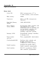
Specifications
Main Unit . . . . . . . . . . . . . . . . . . . . . . . . . . . . . . . . . . . . .
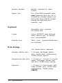
Keyboard . . . . . . . . . . . . . . . . . . . . . . . . . . . . . . . . . . . . . .
Massstorage . . . . . . . . . . . . . . . . . . . . . . . . . . . . . . . . . . .
Power Supply . . . . . . . . . . . . . . . . . . . . . . . . . . . . . . . . . .
Environmental Requirements. . . . . . . . . . . . . . . . . . . . . .
Physical Characteristics . . . . . . . . . . . . . . . . . . . . . . . . . .
Video and Display Options. . . . . . . . . . . . . . . . . . . . . . . .
Other Apex Options. . . . . . . . . . . . . . . . . . . . . . . . . . . . .
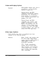
Parallel Port Pin Assignments . . . . . . . . . . . . . . . . . . . . .
Serial Port Pin Assignments. . . . . . . . . . . . . . . . . . . . . . .
Keyboard Connector Pin Assignments . . . . . . . . . . . . . .
Parallel Port Loop-back Connector Pi Assignments ...
Serial Port Loop-back Connector Pin Assignments . . . .
viii Contents
B-1
B-2
B-2
B-3
B-3
B-3
B-4
B-4
B-7
B-8
B-9
B-9
B-9
Appendix C
Power-on Diagnostics
C-1
Timer and CMOS RAM Check. . . . . . . . . . . . . . . . . . . . . . . . C-2
RAM Check . . . . . . . . . . . . . . . . . . . . . . . . . . . . . . . . . . . . . . . C-3
Keyboard Controller and Keyboard Check. . . . . . . . . . . . . . . . C-3
Floppy Disk Drive Seek Check. . . . . . . . . . . . . . . . . . . . . . . . . C-4
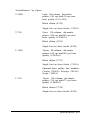
System Device Check . . . . . . . . . . . . . . . . . . . . . . . . . . . . . . . .
Appendix D
Performing System Diagnostics
Starting System Diagnostics . . . . . . . . . . . . . . . . . . . . . . . . . . .
Modifying the DEVICE LIST . . . . . . . . . . . . . . . . . . . . . . . . . .
Selecting a Test . . . . . . . . . . . . . . . . . . . . . . . . . . . . . . . . . . . . .
Resuming From an Error . . . . . . . . . . . . . . . . . . . . . . . . . .
System Board Check . . . . . . . . . . . . . . . . . . . . . . . . . . . . . . . . .
Memory Check . . . . . . . . . . . . . . . . . . . . . . . . . . . . . . . . . . .
Keyboard Check . . . . . . . . . . . . . . . . . . . . . . . . . . . . . . . . . . . .
Monochrome Display Adapter and CRT Check . . . . . . . . . . .
Monochrome Adapter Check. . . . . . . . . . . . . . . . . . . . . .
Attribute Check . . . . . . . . . . . . . . . . . . . . . . . . . . . . . . . .
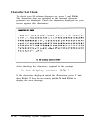
Character Set Check . . . . . . . . . . . . . . . . . . . . . . . . . . . .
Video Check . . . . . . . . . . . . . . . . . . . . . . . . . . . . . . . . . . .
Sync Check . . . . . . . . . . . . . . . . . . . . . . . . . . . . . . . . . . . .
Run All Above Checks . . . . . . . . . . . . . . . . . . . . . . . . . .
Color Graphics Adapter and CRT Check . . . . . . . . . . . . . . . .
Color Graphics Adapter Check . . . . . . . . . . . . . . . . . . . .
Attribute Check . . . . . . . . . . . . . . . . . . . . . . . . . . . . . . . .
Character Set Check . . . . . . . . . . . . . . . . . . . . . . . . . . . .
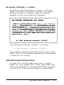
40-column Character Set Check . . . . . . . . . . . . . . . . . . .
320x200 Graphics Mode Check. . . . . . . . . . . . . . . . . . . .
640x200 Graphics Mode Check. . . . . . . . . . . . . . . . . . . .
Screen Paging Check . . . . . . . . . . . . . . . . . . . . . . . . . . . .
Light Pen Check . . . . . . . . . . . . . . . . . . . . . . . . . . . . . . . .
Color Video Check . . . . . . . . . . . . . . . . . . . . . . . . . . . . . .
Sync Check . . . . . . . . . . . . . . . . . . . . . . . . . . . . . . . . . . .
Run All Above Checks . . . . . . . . . . . . . . . . . . . . . . . . . .
D-1
D-3
D-5
D-6
D-7
D-8
D-9
D-10
D-11
D-12
D-12
D-13
D-13
D-13
D-14
D-15
D-15
D-16
D-17
D-17
D-18
D-19
D-20
D-21
D-21
D-21
Contents ix
Floppy Disk Drives and Controller Check . . . . . . . . . . . . . . . .
Formatting a Diskette . . . . . . . . . . . . . . . . . . . . . . . . . . .
Starting the Floppy Disk Drive Check . . . . . . . . . . . . . .
Sequential Seek Check . . . . . . . . . . . . . . . . . . . . . . . . . .
Random Seek Check . . . . . . . . . . . . . . . . . . . . . . . . . . . .
Write, Read Check . . . . . . . . . . . . . . . . . . . . . . . . . . . . . .
Speed Check . . . . . . . . . . . . . . . . . . . . . . . . . . . . . . . . . . .
Run All Above Checks . . . . . . . . . . . . . . . . . . . . . . . . . .
Math Coprocessor Check (8087-1) . . . . . . . . . . . . . . . . . . . . .
Parallel Port (Printer Interface) Check . . . . . . . . . . . . . . . . . .
Parallel Port (on Video Adapter) Check . . . . . . . . . . . . . . . . .
Serial Port (RS-232C) Check . . . . . . . . . . . . . . . . . . . . . . . . . .
Alternate Serial Port Check . . . . . . . . . . . . . . . . . . . . . . . . . . .
Dot-matrix Printer Check. . . . . . . . . . . . . . . . . . . . . . . . . . . . .
Hard Disk Drives and Controller Check . . . . . . . . . . . . . . . . .
Seek Check . . . . . . . . . . . . . . . . . . . . . . . . . . . . . . . . . . . .
Write, Read Check . . . . . . . . . . . . . . . . . . . . . . . . . . . . .
Error Detection and Correction Check . . . . . . . . . . . . . .
Read, Verify Check . . . . . . . . . . . . . . . . . . . . . . . . . . . . .
Run All Above Checks . . . . . . . . . . . . . . . . . . . . . . . . . .
Error Codes and Messages . . . . . . . . . . . . . . . . . . . . . . . . . . . . .
Appendix E
Physically Formatting a Hard Disk
Formatting and Checking Options . . . . . . . . . . . . . . . . . . . . .
Reformatting a Used Disk . . . . . . . . . . . . . . . . . . . . . . . .
Formatting a New Disk . . . . . . . . . . . . . . . . . . . . . . . . . . .
Starting the Formatting Process . . . . . . . . . . . . . . . . . . . .
Conditional Format (Normal) . . . . . . . . . . . . . . . . . . . . . . . . .
Unconditional Format . . . . . . . . . . . . . . . . . . . . . . . . . . . . . . .
Destructive Surface Analysis . . . . . . . . . . . . . . . . . . . . . . . . . . .
Non-destructive Surface Analysis. . . . . . . . . . . . . . . . . . . . . . .
x
Contents
D-22
D-22
D-23
D-24
D-24
D-25
D-25
D-26
D-26
D-27
D-28
D-28
D-30
D-30
D-31
D-32
D-33
D-34
D-34
D-35
D-36
E-2
E-3
E-4
E-4
E-5
E-7
E-10
E-11
Appendix F
Preparing a Hard Disk for Use
Creating the MS-DOS Partition . . . . . . . . . . . . . . . . . . . . . . .
Formatting the MS-DOS Partition . . . . . . . . . . . . . . . . . . . . . .
Copying the Remaining Files to the Hard Disk . . . . . . . . . . . .
Creating the AUTOEXEC.BAT File ..........................
Booting From the Hard Disk. . . . . . . . . . . . . . . . . . . . . . . . . . .
F-2
F-4
F-6
F-7
F-8
Glossary
Index
Contents xi
Introduction
Your Apex” personal computer is powerful, versatile, and easy
to use. After setting up your system with the simple instructions
in this manual, you’ll soon be using your favorite software
programs.
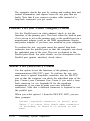
The Apex computer is available in these configurations:
The Apex 100 provides two 360KB (kilobyte) diskette
drives
The Apex 100\20 provides one 20MB (megabyte) hard
disk drive and one 360KB diskette drive.
Both models come with 640KB of internal memory, five
internal option slots, an MGA (multi-graphics adapter) card,
and built-in serial and parallel interfaces. You can connect
either a monochrome or color graphics monitor to the MGA
card in the computer.
®
Your computer comes with version 3.3 of MS-DOS —an
®
operating system by Microsoft. In addition to the introduction
to MS-DOS provided in this manual, you’ll find a
comprehensive reference manual for the operating system
pack4 in the box with your computer.
As a supplement to MS-DOS, Epson has included several timesaving utilities that make MS-DOS easier to use: HELP,
®
MENU, and XTREE. The HELP program lets you display
information on the screen about any MS-DOS command.
MENU provides an easier way to run many of the most
common MS-DOS commands. XTREE is a file management
utility that simplifies all file and directory operations; it is
especially useful for managing data on a hard disk.
Introduction 1
As your needs grow, so can your computer; you can expand your
system by adding a wide variety of options. You can install most
option cards compatible with the IBM” Personal Computer.
For example, you can add an internal modem card to provide
data communications. If you use software that executes lengthy
mathematical calculations, you may want to install an 8087-1,
10 MHz math coprocessor to speed up processing.
How to Use This Manual
This manual explains how to set up and care for your computer.
It also describes how to use your computer and run diagnostic
checks. The instructions in this manual apply to both models
of the Apex computer except where indicated otherwise.
You probably don’t need to read everything in this book; see
the following chapter summaries.
Chapter 1 provides simple step-by-step instructions for setting
up your computer. On the back cover foldout are illustrations
identifying the different parts of the computer; you may want
to refer to this while you are setting up your system.
Chapter 2 covers some general operating procedures, including
how to use and care for your disks and disk drives.
Chapter 3 provides basic instructions for using MS-DOS with
your computer.
Chapter 4 describes how to install option cards in your computer.
Chapter 5 contains troubleshooting tips in case you encounter
any problems while using your computer.
Appendix A explains how to change the DIP switch settings
and run the Setup program if you modify your computer’s
configuration.
Appendix B gives the technical specifications for the computer.
2 Introduction
Appendix C provides information on the power-on diagnostics.
Appendix D outlines the system diagnostic checks you can
perform on your computer. If you are having trouble with any
part of the hardware, you may want to run some of these
diagnostic checks.
Appendix E describes how to perform a hardware-level format
on the hard disk. You need to do this only if you are having
serious problems with the hard disk in your Apex 100\20 or if
you have installed a new hard disk that has not received this
type of format. (This is not the same type of format provided by
the MS-DOS FORMAT command.)
Appendix F explains how to prepare a new hard disk for use.
You need to follow these instructions only if you have installed
a new hard disk in your computer or if you need to repartition
or reformat the one you have been using.
At the back of the manual you’ll find a glossary of computer
terms and an index.
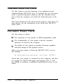
Where to Get Help
Customer service for Epson products is provided by a network
of authorized Epson Customer Care Centers throughout the
United States.
Call the Epson Consumer Information Center at
1-800-922-8911 for the following:
Customer Care Center referrals
Technical support referrals
Information on Epson User Groups.
To locate or purchase accessories or supplies, contact your
nearest Epson dealer or call 1-800-873-7766.
Introduction 3
Chapter 1
Setting Up Your System
Setting up your Apex personal computer is easy. Just follow the
nine steps in this chapter. You may want to leave the back
cover foldout open so you can refer to the two illustrations
identifying the different parts of the computer.
Note:
If you have experience setting up computers, you may prefer
to follow the brief instruction on the Read This First card
included with this manual. (Turn to this chapter if you have
any questions and for instructions on copying your system
diskettes.)
1 Unpacking
As you unpack the different parts of your computer system, be
sure to inspect each piece. If anything is missing or looks
damaged, contact the place where it was purchased for missing
items or replacements. If you cannot obtain the necessary part
or parts, call your Epson Customer Care Center. Please have
the computer’s serial number ready when you call.
Setting Up Your System
1-1
Besides this manual, you should have the following:
The computer and power cord
The keyboard with attached cable
Four diskettes: three that contain the MS-DOS operating
system (Startup, Operating 1, and Operating 2), and a
Reference diskette
An MS-DOS Reference Manual.
In addition to these items, you need a compatible video
monitor to use with the computer. With the MGA (multigraphics adapter) card in the computer, you can use a
monochrome or color graphics monitor.
Note
If you chose a monitor that is not compatible with the MGA
card, you'll also need the appropriate display adapter card to
use with that monitor.
You’ll find a warranty card and a registration card with the
computer. Fill out the registration card and mail it to Epson.
With this card on file, Epson can send you update information.
Be sure to keep your packing materials. They provide the best
protection for your computer if you need to transport it later.
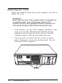
Removing the Diskette Drive Protector Card
A protective piece of cardboard occupies the slot of each
diskette drive in your computer. This card is inserted at the
factory to protect the read/write heads in the drive.
Be sure to remove the card from each diskette drive before you
turn on the computer. Turn the diskette drive latch up until it
is horizontal and carefully pull out the card.
1-2
Setting Up Your System
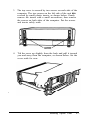
Save the protector card and reinsert it whenever you move the
computer. If you don’t plan to use your computer for a week or
more, reinsert the card to help prevent dust from entering the
disk drive.
2
Choosing a Location
Before you set up your computer, it is important to choose the
right location. Select a spot that provides the following:
A large, sturdy desk or table that can easily support the
weight of your system, including all its components. Make
sure the surface is hard and flat. Soft surfaces like beds and
carpeted floors attract static electricity, which can erase
data on your disks and damage the computer’s circuitry.
Soft surfaces also prevent proper ventilation.
Good air circulation. Air must be able to move freely under
the system as well as behind it. Leave several inches of
space around the computer to allow ventilation.
Setting Up Your System
1-3
Moderate environmental conditions. Protect your
computer from extremes in temperature, direct sunlight, or
any other source of heat. High humidity also hinders
operation, so select a cool, dry area. Avoid dust and smoke,
which can damage disks and disk drives and cause you to
lose valuable data.
Appropriate power sources. To prevent static charges,
connect all your equipment to three-prong, 120-volt
grounded outlets. You need one outlet for the computer,
one for the monitor, and additional outlets for a printer
and any other peripherals. You can plug one peripheral into
the auxiliary power outlet on the back panel of the
computer, reducing the number of wall outlets you need.
(The current required by the peripheral must not exceed
1 amp.)
No electromagnetic interference. Locate your system away
from any electrical device, such as a telephone, that
generates an electromagnetic field.
Connecting a Monitor
Your computer comes with an MGA (multi-graphics adapter)
card installed. This card controls the monitor and provides the
connection to attach the monitor to the computer. You can
connect a monochrome or color graphics monitor to this card.
Note
If you are using another type of monitor with your
computer—such as an EGA (enhanced grapics adapter) or
VGA (video graphics array)—you need a compatible display
adapter card to control if. If the optional card is not already
installed in the computer, you need to do this before you can
connect the monitor. See Chapter 4 Fox instructions on
installing an option card (in this case, the video card).
1-4
Setting Up Your System
The procedure you use to connect your monitor to the
computer depends on the type of monitor you have. See your
monitor manual for detailed instructions or follow these
general guidelines:
1. Place your monitor on top of or near the computer. It is
easiest to connect the monitor cable if the backs of the
monitor and the computer are facing you.
2. If necessary, connect the monitor cable to the monitor.
(Some monitors-such as the Apex-come with
permanently attached cables.)
3. Connect the monitor cable to the video card connector on
the back of the computer, as shown below. If the plug has
retaining screws, tighten them by hand or with a
screwdriver, depending on the screw type.
4. If necessary, plug the monitor’s power cord into the
monitor’s power inlet.
Setting Up Your System
1-5
5. Plug the other end of the power cord into an electrical
outlet.
Note
If the monitor has the proper type of plug, you can plug
at into the auxiliary power outlet next to the AC power
inlet on the back of the computer.
6. If you connected the monitor to the MGA card in the
computer, set the color/mono monitor switch on the card
to match the type of monitor you are using, either color or
monochrome.
7. The Apex computer is set up to use an 80-column, color
monitor. If you are connecting any other type of monitor,
you need to change two of the DIP switches (1-5 and 1-6)
on the computer’s front panel to match the monitor and
display adapter you are using. See Appendix A for
instructions on changing the DIP switches.
1-6
Sating Up Your System
4
Connecting a Peripheral Device
The computer has a parallel interface and a serial interface on
the back panel; so you can easily connect a printer or other
device with either type of interface.
For example, you can use the parallel port to connect a parallel
printer; most printers have a parallel interface. You can use the
serial port to connect a serial printer, a serial mouse, or an
external modem.
Follow the steps in this section to connect a printer or other
peripheral device to either the parallel or serial interface.
Using the Parallel Interface
®
The parallel interface on the computer is Centronics
compatible and uses a 25-pin connector. To connect a parallel
printer to your computer, you need an IBM-compatible printer
cable. If you are not sure which one you need, check with the
store where you purchased the computer.
Once you have the correct printer cable, follow these steps to
connect the printer to the parallel interface on the computer:
1. Place the printer next to your computer.
2. One end of the printer cable has a 25-pin, male connector.
Connect this end to the parallel port on the back panel of
the computer, as shown in the following illustration. If the
plug has retaining screws, tighten them by hand or with a
screwdriver, depending on the screw type.
Setting Up Your System
1-7
3. Connect the other end of the cable to the printer as shown
below. If the printer has retaining clips on each side of the
printer port, squeeze them together to secure the cable.
4. Plug the printer’s power cord into an electrical outlet.
1-8
Setting Up Your System
Using the Serial Interface
If you have a printer, modem, mouse, or any other peripheral
with a serial interface, you can connect it to the serial
(RS-232C) port on the back of the computer. The Apex uses a
25-pin male connector, so be sure you have the proper cable. If
you are not sure, check with the store where you bought the
computer and printer.
To connect a serial device, follow the same steps outlined
above for a parallel device, but connect the cable to the serial
port.
Setting up the serial port for a printer
If you are using a serial printer but your software does not
support a serial printer, you must do two things before you can
use the serial printer:
Set up the data transmission parameters for the port
Tell the computer to redirect printer data from the parallel
port to the serial port.
Setting Up Your System
1-9
The Setup program on your Reference diskette lets you define
the baud rate, parity, data length, and number of stop bits for a
primary and a secondary serial port. See “Running the Setup
Program” in Appendix A for instructions.
To redirect the printer data you can use either the MS-DOS
MODE command or the Epson MENU utility. (MENU
provides an easy way to use MODE. For instructions, see the
description of the Mode Settings option of the MENU program
in your MS-DOS Reference Manual.)
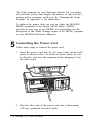
5
Connecting the Power Cord
Follow these steps to connect the power cord:
1. Insert the power cord into the AC power inlet on the back
panel, as shown below. To avoid an electric shock, be sure
to plug the cord into the computer before plugging it into
the wall socket.
2. Plug the other end of the power cord into a three-prong,
120-volt, grounded electrical outlet.
1-10 Setting Up Your System
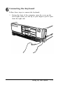
6
Connecting the Keyboard
Follow these steps to connect the keyboard:
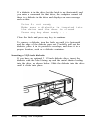
1. Facing the front of the computer, open the cover on the
lower right comer; use the tip of your finger to pull it open
from the right side.
Setting Up Your System
1-11
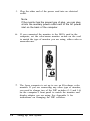
2. Plug the keyboard cable into the socket, as shown below.
Do not force the connector, but be sure to insert it all the
way.
3. Push the cable into the notch at the right side of the
computer, as shown below, so the cable leads away to the
right side of the computer.
4. Close the keyboard cable cover.
1-12
Setting Up Your System
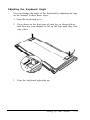
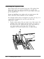
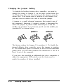
Adjusting the Keyboard Angle
You can change the angle of the keyboard by adjusting the legs
on the bottom. Follow these steps:
1. Turn the keyboard over.
2. Press down on the front part of each leg, as shown below,
and then use your thumbs to lift up the legs until they lock
into place.
3. Turn the keyboard right-side up.
Setting Up Your System
1-13
7
Turning On the Computer
Before you turn on your computer, read the following safety
rules to avoid accidentally damaging the computer or injuring
yourself:
Never turn the computer on with a protector card in the
diskette drive.
Do not unplug cables from the computer when the power
switch is on.
Never turn off or reset your computer while a disk drive
light is on. This can destroy data stored on disk or make a
whole disk unusable.
Always wait at least five seconds after you switch off the
power before you switch it on again. Turning the power off
and on rapidly can damage the computer’s circuitry.
Do not leave a beverage on top of or next to your system or
any of its components. Spilled liquid can damage the
circuitry of your equipment.
Do not attempt to dismantle any part of the computer.
Only remove the cover to install and remove optional
devices. If there is a hardware problem you cannot solve
after reading the appropriate section in Chapter 5 on
troubleshooting, contact your Epson Customer Care
Center.
Always turn off the power, disconnect all cables, and wait
five seconds before you remove the computer’s cover.
Follow these steps to turn on your system:
1. Turn on the monitor, printer, and any other peripheral
devices connected to the computer.
1-14 Setting Up Your Systems
2. To turn on the computer, press the power switch.
The power indicator on the front panel lights up. After a few
seconds, the computer starts to perform an internal self test.
This is a series of checks the computer completes each time you
turn it on to make sure everything is working correctly. If
anything is wrong, an error message appears on the screen.
If you cannot see the screen display clearly, use the controls on
your monitor to adjust the brightness and contrast until
characters on the screen are clear and bright.
8
Loading MS-DOS
Once the computer completes its self test, it tries to load
MS-DOS, the operating system, into the computer’s memory.
MS-DOS must be in the computer’s memory before you can
run any application program-such as a word processing
program or a spreadsheet program.
If you have the Apex 100\20, the computer automatically
loads MS-DOS from the hard disk and you see the MS-DOS
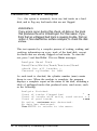
command prompt on the screen:
C:\>
Go on to the section below called “The Command Prompt.”
Setting Up Your System
1-15
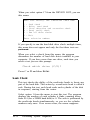
If you have the Apex 100 (no hard disk), the computer does
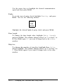
not load MS-DOS, but instead displays the following:
Non-system disk or disk error
Insert system diskette in drive A
and strike any key when ready
These messages tell you that you need to insert the MS-DOS
Startup (system) diskette in the top drive, drive A, so the
computer can load the operating system. Follow the
instructions below.
Note
You can turn on the computer with Startup diskette in the
drive. If you do this, the computer loading MS-DOS form
the diskette and you do not see the error message.
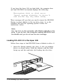
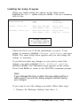
Loading MS-DOS On the Apex 100
Follow these steps to load MS-DOS from a diskette in drive A:
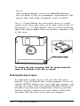
1. Insert the Startup diskette into drive A (the top diskette
drive), as shown below. Hold the diskette with the label
facing up and the read/write slot leading into the drive.
1-16 Setting Up Your System
2. When the diskette is in all the way, turn the latch down
(clockwise) to lock the diskette in place. (For detailed
instructions on inserting diskettes, see Chapter 2.)
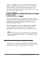
3. Press any key. The computer loads MS-DOS into its
memory where it will remain until you turn off the
computer. Once MS-DOS is loaded, you see a date prompt,
such as the following, which appears every time you load
MS-DOS:
Current date is Mon 7-24-1989
Enter new date (mm-dd-yy):
4. If the date is correct, press Enter to leave it unchanged. To
correct the date, enter it in the order shown, using one or
two digits for the month, day, and year, separated by
dashes. For example, to set the date for August 30, 1989,
you would type the following:
8-30-89
5. Next the screen displays the time prompt, such as this:
Current time is 09:32:21.77
Enter new time:
If the time is correct, press Enter to leave it unchanged. To
correct the time, use a 24-hour clock to enter the time in
the format shown, using one or two digits for each part
(you can omit the seconds, if desired). For example, to
change the time to 1:30 p.m., you would type the following:
13:30
The screen displays the MS-DOS command prompt:
A>
Setting Up Your System
1-17
You need to set the date and time this way only once; the
computer’s real-time clock keeps track of the date and time
even when the computer is off. The next time you load
MS-DOS, you can just press Enter when you see each of
these prompts to accept the displayed date and time.
MS-DOS updates months and years correctly-whether the
month has 31, 30, 29, or 28 days—and even accounts for leap
years. You may need to change the time later, however, to
accommodate a change such as daylight savings time.
Note
You can also change the date and time with the Setup
program or with the MS-DOS DATE and TIME commands.
The Setup program is described in Appendix A. The DATE
and TIME commands are described below for the Apex
100\20 and in the MS-DOS manual.
The Command Prompt
The command prompt tells you that MS-DOS is loaded and
your computer is ready to receive instructions. It also identifies
the current operating drive: A, B, or C. The command prompt
appears on the screen whenever you load MS-DOS, complete
an MS-DOS command, or exit an application program.
On the Apex 100, the top diskette drive is drive A and the
bottom diskette drive is B. On the Apex 100\20, the diskette
drive is A and the hard disk is drive C. MS-DOS reserves the
label B for a second diskette drive, whether or not it is
installed.
If you load MS-DOS from a diskette in drive A, the command
prompt looks like this:
A>
1-18
Setting Up Your System
If you load MS-DOS from the hard disk, the command prompt
looks like this:
C:\>
The hard disk prompt is different because the Apex 100\20 has
been set up with a special command that changes the
command prompt to show the current directory. (A directory
consists of a group of files stored together under an identifying
name. See Chapter 3 for a complete description of directories.)
The command that changes the command prompt is called
PROMPT and it is stored in a file called AUTOEXEC.BAT.
The AUTOEXEC.BAT file contains a series of commands that
your computer performs each time it loads MS-DOS. You can
add commands to this file to automate a set of procedures you
normally perform each time you turn on the computer. See
Chapter 3 for more information about using the
AUTOEXEC.BAT file.
Note
For consistency, this manual uses the same format for the
command prompt for both drive A and drive C, that is: A>
and C>.
Setting the Time and Date on the Apex 100\20
The first time you use your Apex 100\20, you need to set the
correct date and time for the computer’s real-time clock.
Follow these steps:
1. At the C> prompt, type DATE and press Enter. The screen
displays the following:
Current date is Mon 7-24-89
Enter new date (mm-dd-yy):
Setting Up Your System
1-19
2. If the date is correct, press Enter to leave it unchanged. To
change the date, type the appropriate numbers for the
month, day, and year, as shown. For example, to set the
date for August 30, 1989, type the following and press
Enter:
8-30-89
3. Next type TIME and press Enter. The screen displays the
following:
Current time is 09:32:21.0
Enter new time:
If the time is correct, press Enter to leave it unchanged.
To change it, enter the time in the format shown using a
24-hour clock. You can omit the seconds, if desired. For
example, to change the time to 1:30 p.m., type the
following and press Enter:
13:30
You need to set the date and time this way only once; the
computer’s real-time clock keeps track of the date and time
even when the computer is off. it updates months and years
correctly-whether the month has 31, 30, 29, or 28 days-and
accounts for leap years. You may need to change the time later,
however, to accommodate a change such as daylight savings
time.
Note
You can also change the date and time with the Setup
program, described in Appendix A.
1-20
Setting UP Your System
9
Copying System Diskettes
Now that you have set up your system and loaded MS-DOS, it
is important that you make copies of your MS-DOS and
Reference diskettes right away. Use only the copies (usually
called “working copies”) for daily use and store the originals in
a safe place.
The procedure for copying diskettes depends on the number of
diskette drives you have. Follow the instructions below for your
model. You’ll need four blank, 360KB, double-sided, doubledensity, 5 1/4-inch diskettes.
Note
If your computer has only one diskette drive and no hard
disk, follow the instructions in Chapter 3 for copying
diskettes with only one drive.
Be sure to label each diskette as you copy it. Write on the label
before you attach it to the diskette to prevent damaging the
diskette.
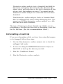
Copying Diskettes on the Apex 100
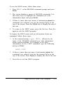
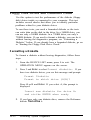
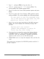
1. The A> prompt should be on the screen; if it is not, follow
the steps in the previous section, “Loading MS-DOS on the
Apex 100.”
2. Remove the Startup diskette from the cop drive by turning
the latch up and pulling out the diskette. Then insert the
diskette labelled “Operating 1” and turn the latch down to
secure the diskette. The Operating 1 diskette contains the
DISKCOPY program which you will use to make the
copies.
Setting Up Your System
1-21
3. Insert a blank 5 1/4-inch 360KB diskette in drive B (the
bottom drive) and turn the latch down to secure the
diskette.
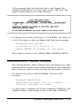
4. Type the following and press Enter.
DISKCOPY A: B:
The screen displays these prompts:
Insert SOURCE diskette in drive A:
Insert TARGET diskette in drive B:
Press any key when ready ...
5. Drive A (the top drive) already contains a diskette you
want to copy (the source diskette) and drive B contains the
blank target diskette, so just press any key. The
DISKCOPY program begins the copy process.
If the diskette in drive B is not formatted, the DISKCOPY
program formats it. (Formatting prepares a diskette to store
data and is described in Chapter 3.) Then the program
copies the contents of the diskette in drive A to the
formatted diskette in drive B. When the copy is complete,
you see this prompt:
Copy another diskette (Y/N)?
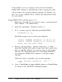
6. Press Y so you can make a copy of the Operating 2 diskette.
Again, you see these prompts:
Insert SOURCE diskette in drive A:
Insert TARGET diskette in drive B:
Press any key when ready . . .
7. Remove the original Operating 1 diskette from drive A and
the copy from drive B. Insert the Operating 2 diskette in
drive A and another blank diskette in drive B. Then follow
the instructions above and the prompts on the screen to
make a copy of this diskette.
1-22
Setting Up Your System
8. Repeat the procedure for the Startup diskette and the
Reference diskette.
9. When you finish copying the last system diskette and the
Copy another diskette (Y/N)? prompt
appears, press N to return to the MS-DOS command
prompt.
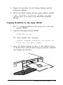
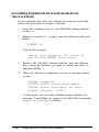
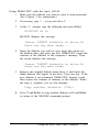
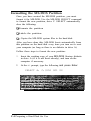
Copying Diskettes on the Apex l00\20
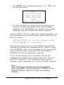
1. The C> prompt should be on the screen; if it is not, type
C : and press Enter.
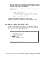
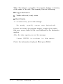
2. Type the following and press Enter:
DISKCOPY A: A:
The screen displays these messages:
Insert SOURCE diskette in drive A:
Press any key when ready . . .
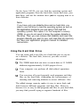
3. insert the Startup diskette in drive A (the diskette drive),
as shown below, with the label facing up and the read/write
slot leading into the drive.
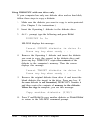
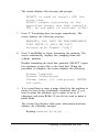
Setting Up Your System
1-23
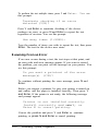
Then press any key. The DISKCOPY program copies the
contents of the Startup diskette to the computer’s memory,
and then you see the following:
Insert TARGET diskette in drive A:
Press any key when ready . . .
4. Remove the Startup diskette and insert a blank diskette
(which is to be the target) in the drive. Then press any key.
If the diskette is not formatted, the DISKCOPY program
formats it. (Formatting prepares a diskette to store data and
is described in Chapter 3.) Then the program begins
copying the data from the computer’s memory to the
formatted diskette. When the copy is complete, you see
this prompt:
Copy another diskette (Y/N)?
5. Press Y so you can make a copy of the Operating 1 diskette.
Again, you see the prompt to insert the source diskette.
6. Remove the copy of the Startup diskette, which you just
made, and insert the Operating 1 diskette in the drive.
Then press any key. Continue following the prompts on
the screen to make a copy of this diskette, as you did the
Startup diskette.
7. Repeat the procedure to copy the Operating 2 diskette and
then the Reference diskette.
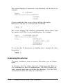
8. When you finish copying the last diskette and the Copy
another diskette (Y/N)? prompt appears, press
N to return to the MS-DOS command prompt.
1-24
Setting Up Your System
Chapter 2
Using Your Computer
This chapter covers the following basic procedures for using
your computer:
Changing the operating speed
Using special keys on the keyboard
Interrupting a command or program
Resetting and turning off the computer
Using disks and disk drives.
Changing the Operating Speed
Your computer can operate at two speeds: 4.77 MHz or
10 MHz. At 10 MHz, the computer performs all tasks faster,
and you will probably use this speed for almost everything you
do. Certain application programs, however, have specific
timing requirements for diskette access and can run only at the
slower speed. See the manual for your application program to
determine if this is the case.
Use the CPU switch on the front panel to change the speed.
To access the switch, open the cover below the disk drives;
press down slightly on the tab to open the cover. Move the
switch left for 4.77 MHz or right for 10 MHz.
Using Your Computer
2-1
WARNING
You can change the speed while the computer is on, but do
not change it while you are running a program. Complete
your current operation, exit the program to the MS-DOS
command prompt, and then change the speed.
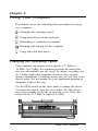
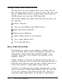
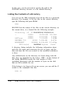
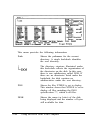
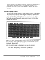
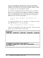
Using Special Keys
Certain keys on your keyboard serve special functions when
your computer is running application programs. The following
illustration shows the keyboard, and the table that follows
describes the special keys.
2-2
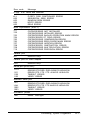
Key
Purpose
F1-F10
Perform special functions within application
programs.
Tab
Moves the cursor one tab to the right in normal
mode (and one tab to the left in shift mode when
using some application programs).
Ctrl
Works with other keys to perform special (control)
functions, such as editing operations.
Shift
Produces uppercase characters or the top
symbols on the keys when used with the main
character keys. Produces lowercase characters
when Caps Lock is on.
Alt
Works with other keys to enter alternate character
codes or functions.
Using Your Computer
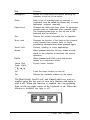
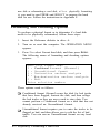
Key
Purpose
Backspace
Moves the cursor back one space, deleting the
character to the left of the cursor.
Enter
Ends a line of keyboard input or executes a
command (may be called the Return key in some
application program manuals).
Caps Lock
Changes the letter keys from lower- to uppercase;
changes back to lowercase when pressed again.
The numeric/symbol keys on the top row of the
keyboard are not affected.
Esc
Cancels the current command line or operation.
Num Lock
Changes the function of the keys on the numeric/
cursor keypad from numeric entry to cursor
positioning; changes back when pressed again.
Scroll Lock
Controls scrolling in some applications.
Break
When pressed with the Ctrl key, sends a break
signal to the computer to terminate the current
operation.
PrtSc
When pressed with Shift. prints the screen
display on a dot-matrix printer.
Home, End
PgUp. PgDn
Control cursor location.
Ins
Turns the insert function on and off.
Del
Deletes the character marked by the cursor.
The Num Lock, Scroll Lock, and Caps Lock keys work as
toggles; press the key once to turn on a function and again to
turn it off. When the function is enabled, the corresponding
light on the top right comer of the keyboard is on. When the
function is disabled, the light is off.
Using Your Computer
2-3
Stopping a Command or Program
You may sometimes need to stop a command or program while
it is running. Many application programs provide a command
you can use to cancel or even undo an operation. If you have
entered an MS-DOS command that you want to stop, try one
of the following commands:
Hold down the Ctrl key and press C
Hold down the Ctrl key and press Break.
These methods may also work in your application program. If
you cannot stop a particular operation, however, you may need
to reset the computer, as described in the following section.
Cation
It is best not to turn off the computer to stop a program or
command. If you have created new data that you have not
yet stored, it will be erased if you turn off the computer. The
Apex stores your data in its memory until you save it; but
the memory area is erased each time you turn off or reset the
computer.
Resetting the Computer
Occasionally, you may want to clear the computer’s current
settings or its memory without turning it off. This is called
resetting the computer.
You can reset the computer to reload the operating system. You
may need to do this if an error occurs and the computer does
not respond to anything you enter on the keyboard; you can
reset the computer and try again. However, resetting erases any
data in the computer’s memory that you have not stored; so
reset your computer only if necessary.
2-4
Using Your Computer
WARNING
Do not reset the computer to extra Do not the program unless you have
to Same application progress classify and store new data
when you exit the program. If you reset the computer
without properly exiting the program, you may lose data
To reset the computer, MS-DOS must be either on the hard
disk or on a diskette in drive A; so if you have the Apex 100,
insert the Startup diskette in drive A.
There are three ways to reset. Because each is more powerful
than the last, try them in the order listed here:
1. If you are using MS-DOS, hold down Ctrl and Alt and press
the Del key. The screen goes blank for a moment and then
the computer should reload MS-DOS. If it doesn’t, try the
second method.
2. Press the RESET button on the front panel. This method
works even when the keyboard does not respond to your
commands. if this does not correct the problem, try the
third method.
3. Remove any diskette from the diskette drive(s). Turn
off the computer and wait five seconds. If you have the
Apex 100, insert the Startup diskette in drive A. Then
turn the power back on.
Turning Off the Computer
Before turning off your computer, be sure to save your data and
exit the program you are using. Then remove any diskettes
from the disk drives.
Turn off the computer first and then turn off the monitor and
any peripherals.
Using Your Computer 2-5
Using Disks and Disk Drives
The disk drives in your computer allow you to store data on
disk, and then retrieve and use it when you like. The Apex 100
has two 360KB diskette drives and the Apex 100\20 has one
360KB diskette drive and one 20MB hard disk.
This section explains how disks work and tells you how to do
the following:
Choose diskettes
Care for your diskettes and diskette drives
Insert and remove diskettes
Write-protect diskettes
Make backup copies of your diskettes
Use a single diskette drive
Use a hard disk drive.
How Disks Store Data
The diskette you insert in your computer’s diskette drive is
made of flexible plastic coated with magnetic material. It is
enclosed in a square jacket that is slightly flexible. Your
computer stores data on the diskette by recording on the
magnetic surface.
Unlike a diskette, a hard disk is rigid and fixed in place. It is
sealed in a protective case to keep it free from dust and dirt. A
hard disk stores data the same way that a diskette does, but it
works faster and has a much larger storage capacity.
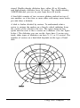
All disks are divided into data storage compartments by sides,
tracks, and sectors. Double-sided diskettes--like the ones you
use in your computer-store data on both sides. There are
concentric rings, called tracks, on the disk in which data is
2-6
Using Your Computer
stored. Double-density diskettes have either 40 or 80 tracks,
and high-density diskettes have 80 tracks. The double-density,
360KB diskettes you use in your Apex have 40 tracks.
A hard disk consists of two or more platters stacked on top of
one another; so it has four or more sides with many more tracks
per side than a diskette.
A disk is further divided by sectors. To understand what a
sector is, picture the spokes on a bicycle wheel radiating from
the center of the wheel to the tire. The space between one
spoke and the next is like a sector on a diskette. (See the figure
below.) The diskettes you use on the Apex have 9 sectors per
track; other types of diskettes can have 8, 15, or 18 sectors. The
number of sectors on a hard disk depends on the type of hard
disk.
Using Your Computer
2-7
Your computer uses the read/write heads in a disk drive to store
and retrieve data on a disk. There is one head above the
diskette and one below, so the drive can write to both sides of
the diskette. To write to a disk, the computer spins it in the
drive to a position where one of the read/write heads can access
the diskette through the read/write slot. The read/write slot on
a diskette exposes the diskette’s magnetic surface so the read/
write head can write on the appropriate area.
Because data is stored magnetically, you can retrieve it, record
over it, and erase it-just as you play, record, and erase music
on a Cassette tape.
Choosing Diskettes
Your computer uses diskettes that are 5 1/4-inch, double-sided,
double-density, 48 TPI (tracks per inch) and have a capacity
of 360KB. The diskette boxes are usually marked DS-DD or
2S-2D, soft sector, 48 TPI. Each. 360KB diskette can hold
approximately 150 pages of text. For best results, choose only
high-quality diskettes with reinforced hub rings.
These diskettes are the same type used on IBM-compatible
computers with 5 1/4-inch drives; so you can use diskettes in
your computer that were prepared and used on another IBMcompatible computer.
Note
Some computers have 5 1/4-inch diskette drives that have a
capacity of 1.2MB. You cannot use 5 1/4-inch diskettes that
have been formatted for 1.2MB in your 360KB drive.
Additionally, if you are using a 360KB diskette that has been
formatted in a 1.2MB drive, your computer may have trouble
reading that diskette,
2-8
Using Your computer
If you have an optional 720KB drive, use 3 l/2-inch, doublesided, double-density, 135 TPI, 720KB diskettes with this drive.
These diskettes contain 80 tracks per side, 9 sectors per track,
and hold up to 720KB of information-approximately 300
pages of text.
Note
You cannot use 3 1/2-inch diskettes that have been
formed for 1.44MB in a 720KB diskette drive.
You need to format new diskettes before you can use them with
MS-DOS. The process of formatting erases all data on a
diskette and prepares it to receive new data; so be sure to
format only new, blank diskettes or diskettes that contain data
you want to erase. See Chapter 3 for instructions on formatting
diskettes.
Caring for Diskettes and Diskette Drives
Follow these basic precautions to protect your diskettes and
avoid losing data:
Do not remove a diskette from the diskette drive or turn off
the computer while the drive light is on. This light
indicates that the computer is copying data to or from a
diskette. If you interrupt this process, you can destroy data.
Remove all diskettes before you turn off the computer.
Keep diskettes away from dust and dirt. Small particles can
scratch the magnetic surface and destroy data. Dust can
also ruin the read/write heads in a diskette drive.
Never wipe, brush, or try to clean diskettes in any way.
Keep diskettes in a moderate environment. They work best
at normal room temperature and in normal humidity. Don’t
leave your diskettes sitting in the sun, or in extreme cold or
heat.
Using Your Computer
2-9
Keep diskettes away from magnetic fields. (Remember that
diskettes store information magnetically.) There are many
sources of magnetism in your home or office, such as
electrical appliances, telephones, and loudspeakers.
Do not place diskettes on top of your monitor or near an
external disk drive.
Never touch a diskette’s magnetic surface. The oils on your
fingertips can damage it. Always hold a diskette by its
protective jacket. If you are using a 3 1/2-u& diskette, do
not slide the metal shutter; this exposes the diskette’s
surface.
Do not place anything on top of your diskettes, and be sure
they do not get bent. A diskette does not rotate properly in
the drive if it has been damaged.
Carefully label your diskettes. Attach labels firmly but
gently, and only along the top of a diskette (next to the
manufacturer’s label). Do not stick several labels on top of
one another; too many labels can make it difficult to insert
and remove the diskette in the drive.
It is best to write on the label before you attach it to the
diskette. If you need to write on a label that is already on a
diskette, use only a soft-tip pen, not a ballpoint pen or a
pencil. Always indicate the storage capacity and density
type on the label.
Store diskettes in a proper location, such as a diskette
container. Do not store diskettes flat or stack them on top
of each other. When you are not using them, keep your
diskettes in their protective envelopes.
2-10
Using Your Computer
If you have the Apex 100\20, follow these additional
precautions to protect your hard disk drive and its data:
Never turn off the computer when the hard disk drive light
is on. This light indicates that the computer is copying data
to or from the hard disk. If you interrupt this process, you
can lose data.
Never attempt to open the hard disk drive. The disk itself
is enclosed in a sealed container to protect it from dust.
If you need to move the computer, be sure to run the
HDSIT program before you turn it off. See “Preparing the
Hard Disk for Moving,” later in this chapter.
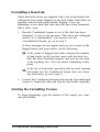
Inserting and Removing Diskettes
To insert a diskette into the drive, hold it with the label facing up
and the read/write slot leading into the drive, as shown below.
Slide the diskette into the slot until it is in all the way. Then
turn the latch down to lock it in a vertical position. This keeps
the diskette in place and enables the read/write heads in the
disk drive to access the diskette.
Using Your Computer
2-11
If a diskette is in the drive but the latch is up (horizontal) and
you enter a command for that drive, the computer cannot tell
there is a diskette in the drive and displays an error message
such as this:
Drive A: not ready
Make sure a diskette is inserted into
the drive and the door is closed
Press any key when ready . . .
Close the latch and press any key to continue.
To remove a diskette, turn the latch up until it is horizontal
and the edge of the diskette pops out. Carefully pull out the
diskette, place it in its protective envelope, and store it in a
proper location, such as a diskette container.
Inserting a 3 1/2-inch diskette
If you have an optional 3 1/2-inch diskette drive, insert the
diskette with the label facing up and the metal shutter leading
into the drive, as shown below. Slide the diskette into the drive
until it clicks into place.
2-12
Using Your Computer
To remove a 3 1/2-inch diskette, press the release button to
release it. When the edge pops out of the drive, pull out the
diskette and store it properly.
WARNING
Never remove a diskette or num off the computer while the
drive indicator light is on. You could lose data. Also, be sure
to remove all diskettes before you turn off the computer.
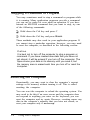
Write-protecting Diskettes
You can write-protect a diskette to prevent its data from being
altered. When a diskette is write-protected, you can read it and
copy data from it, but you cannot store new data on the
diskette or delete any files it contains. If you try to change data on
a write-protected diskette, MS-DOS displays an error message.
To write-protect a 5 1/4-inch diskette, cover the small,
rectangular notch (shown below) with an adhesive writeprotect tab. Write-protect tabs usually come with new
5 1/4-inch diskettes when you buy them.
To remove the write protection, peel off the write-protect tab.
Using Your Computer
2-13
Note
Some program diskettes, such as your MS-DOS diskettes,
have no notch so they are permanently write-protected. This
protects them from being accidentally erased or altered.
On a 3 1/2-inch diskette, the write-protect device is a small
switch on the lower right comer on the back, shown below. To
write-protect a 3 1/2-inch diskette, slide the switch toward the
edge of the diskette until it clicks into position, exposing a hole
in the comer.
To remove the write protection, slide the switch toward the
center of the diskette so the hole is covered.
Making Backup Copies
It is important to make copies of all your data and system
diskettes. Copy all diskettes that contain programs, such as the
original MS-DOS diskettes that come with your computer, and
use only the copies. Store your original MS-DOS diskettes in a
safe place away from your working copies. Back up your data
diskettes regularly, whenever you revise them, to keep them
up-to-date, and store them away from your originals.
2-14
Using Your Computer
Chapter 1 describes how to use DISKCOPY to copy your
MS-DOS and Reference diskettes. To make backups of other
diskettes, use the DISKCOPY command or the MENU
program. See Chapter 3 for more instructions on using
DISKCOPY and MENU.
If you have the Apex 100\20, it is best to put most of the
programs and data files you use regularly on the hard disk. Keep
backup copies of all your program files on diskettes, however,
and regularly copy important data files to diskettes as well. For
more information, see “Backing Up Data” in Chapter 3 and
check your MS-DOS Reference Manual.
Using a Single Diskette Drive
The operating system expects the computer to have at least
two diskette drives, and it displays prompts and messages
accordingly. If your system has only one diskette drive,
MS-DOS treats your one drive like two logical drives. This
helps you perform operations that normally require two diskette
drives.
Usually, MS-DOS recognizes the first diskette drive (the top
drive) as drive A and a second diskette drive as B. If you have
only one diskette drive, MS-DOS recognizes it as both A
and B.
For example, if you give a command to copy from A to B,
MS-DOS copies data from the first diskette you place in the
drive (A) to the computer’s memory. Then MS-DOS prompts
you to insert another diskette (for drive B) and copies the
data from memory to the new diskette. When the copying is
complete, you see a prompt to insert the original diskette (for
drive A).
Because you may often swap diskettes this way, it is important
to remember which diskette is which. One way to avoid
accidentally losing data is to hold the diskette for one drive in
your left hand and the diskette for the other in your right. It is
also a good idea to write-protect your original diskette.
Using Your Computer
2-15
On the Apex 100\20, you can load the operating system and
application programs from the hard disk, create and store your
data there, and use the diskette drive just for copying data to or
from diskettes.
Note
If you have only one diskette drive and no hard disk, you
need to use that drive to load the operating system as well as
the application programs you are using. First load the
operating system; this copies if to the computer's memory
(RAM) so you do not need to leave the system diskette in
the drive. Then you can remove that diskette and insert the
program diskette you want to use, and load that into memory
too. See your application program manual for detailed
instructions.
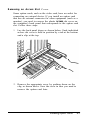
Using the Hard Disk Drive
You can create and revise files on a hard disk just as you do
on a diskette. The hard disk, however, provides several
advantages:
The 20MB hard disk can store as much data as 55 360KB
diskettes-approximately 10,000 pages of text
Your computer can perform all disk-related operations
faster
You can store all your frequently used programs and data
files on the hard disk, eliminating the inconvenience of
inserting and removing diskettes to access different files.
The added storage capacity makes it easy to move back and
forth between different programs and data files. However,
because it is so easy to add programs and files to your hard disk,
you may find yourself trying to organize hundreds of files.
2-16
Using Your Computer
MS-DOS lets you keep related files together in directories and
subdirectories so they are easier to find and use. See Chapter 3
for instructions on how to use directories.
Epson also includes the XTREE utility with MS-DOS. XTREE
provides simple menus that allow you to move, create, delete,
and rename files and directories. This program is especially
useful on the hard disk drive because of the large number of
files the disk can hold. See Chapter 3 for an introduction to
XTREE or see your MS-DOS Reference Manual for complete
instructions.
The hard disk in your Apex 100\20 has been prepared at the
factory so it contains all the MS-DOS system files and
automatically loads MS-DOS when you turn on or reset the
computer. If your computer does not seem to be working
correctly, however, you may need to repeat some of the
procedures to prepare it for use. If you think this may be the
case, see Appendix F for instructions.
Backing up hard disk files
While the hard disk is very reliable, it is essential to back up
your hard disk files onto diskettes in case you lose some data
accidentally. Make copies of all your system and application
program diskettes before copying the programs to the hard disk.
Be sure to copy your data files to diskettes whenever you revise
them to keep your backup diskettes up-to-date.
You can use the MENU utility or the BACKUP command to
back up your hard disk files. Use the MENU utility or the
DISKCOPY command to make copies of your system and
application program diskettes. For instructions on using these
programs, see Chapter 3 (or see your MS-DOS manual).
Using Your Computer
2-17
Preparing the hard disk for moving
If you need to move your Apex 100\20 to a new locationwhether it is across the country or just across the room-there
is a program you should run to protect the hard disk before you
turn off the computer.
The HDSIT program moves the disk drive’s read/write heads to
a region on the disk surface that does not contain data, and
locks them securely in position. This protects the hard disk
from being damaged if the computer is bumped accidentally.
Follow these steps to run HDSIT:
1. Exit any program you are using so the MS-DOS command
prompt is on the screen.
2. Insert the Reference diskette in drive A.
3. Type the following and press Enter:
A:HDSIT
You see a message on the screen that tells you the disk drive’s
read/write heads will remain locked until you reset the
computer or turn the power off and on again. The computer
locks the heads and disables the keyboard. You can now turn
off the computer and prepare to move it to the new location.
2-18
Using Your Computer
Chapter 3
Using MS-DOS With Your Computer
Your computer comes with version 3.3 of MS-DOS. This
operating system manages your computer by organizing the
computer’s memory, controlling the monitor display, receiving
keyboard input, and accessing data.
To communicate with the operating system, you use MS-DOS
commands. How much you need to know about MS-DOS
depends on how you plan to use your computer. If you plan to
use it just to run application programs, the few MS-DOS
commands you’ll need are introduced in this chapter. If you
plan to use advanced features or create your own programs, see
your MS-DOS Reference Manual for a complete description of
MS-DOS.
This chapter covers the following topics:
Starting and exiting MS-DOS
Using drive designators
Types of MS-DOS commands
Entering an MS-DOS command
Creating and managing files
Using directories
Formatting diskettes
Backing up data
Using special Epson utilities
Using an AUTOEXEC.BAT file.
Using MS-DOS With Your Computer
3-1
Starting and Exiting MS-DOS
Before you can run an MS-DOS application program, MS-DOS
must be running in memory. Chapter 1 describes how to load
MS-DOS on your computer.
If you have the Apex 100\20, the computer loads MS-DOS
from the hard disk automatically when you turn on the
computer. If you do not have a hard disk, you need to insert
your working copy of the MS-DOS Startup diskette in drive A
and then turn on the computer to load MS-DOS.
(Alternatively, you can turn on the computer and then insert
the Startup diskette to load MS-DOS.)
If the date and time prompts appear, press Enter to accept the
date and time shown. The screen then displays the MS-DOS
command prompt, A> or C>. This tells you that MS-DOS is
loaded and identifies the current drive.
Before you turn off the computer, make sure the A> or C>
prompt is displayed. Then remove your diskettes, turn off your
computer, and turn off any peripherals.
Starting An Application Program
Once you have loaded MS-DOS, you can start using your
application program. If you have the Apex 100, remove the
Startup diskette from drive A and insert the program diskette
in that drive. If you have the Apex 100\20 and you already
copied the application program to the hard disk, log onto drive
C (and the appropriate directory, if necessary). If the program
is not on the hard disk, insert the diskette in drive A.
Then enter the necessary command to start the application
program, as described in the program’s manual. From this point
on, until you return to the MS-DOS command prompt, refer to
the application program’s manual for any instructions on using
the program.
3-2
Using MS-DOS With Your Computer
Using Drive Designators
MS-DOS uses letters to identify the disk drives in your system.
If you have one diskette drive, it is known as drive A. If you
have two diskette drives, the top one is called drive A and the
bottom drive is B.
If you have a hard disk drive, MS-DOS identifies it as drive C,
even if you have only one diskette drive.
The Default Drive
At any given time, MS-DOS considers one disk drive to be the
default drive. The default drive is the one on which MS-DOS
executes your next command, unless you tell it to do otherwise.
For example, if the default drive is C, and you issue the DIR
(directory) command, MS-DOS lists the files stored on drive C.
if the default drive is A and you type WP and press Enter,
MS-DOS looks on drive A for a file called WP and executes
the instructions in that file.
The MS-DOS command prompt tells you which drive is the
current default. The command prompt consists of the drive
letter followed by a greater-than symbol. (Depending on how
your system has been set up, the command prompt may also
include additional information.) Thus, when you see C>
displayed on your screen, you know that the default drive is C.
The command prompt also lets you know that MS-DOS is
ready to receive a command from you.
If you need to access a file or program on another drive, you
can either change the default drive or specify the other drive
when you give the command.
Using MS-DOS With Your Computer
3-3
Changing the default drive
To change the default drive, type the letter of the drive you
want to change to, followed by a colon. Then press Enter. For
example, to change the default from A to C, type the following
and press Enter:
C:
MS-DOS acknowledges the change by displaying the command
prompt C>. Changing to a new drive is also called logging onto
that drive.
Specifying the drive designator
If you want to access a program or file on another drive without
first changing the default drive, type the drive designator along
with the filename. For example, if you are logged onto drive A
and want to use a file named PROGRAM on drive B, you
would type the following:
B:PROGRAM
MS-DOS loads and executes the file named PROGRAM from
drive B, but stays logged onto drive A.
Types of MS-DOS Commands
Each MS-DOS command is either internal or external. Internal
commands are commands that are built into MS-DOS and can
he used at any time once MS-DOS is loaded into memory.
External commands are stored on your system diskettes as
program files.
If you display a directory of the files on your MS-DOS
diskettes, you see the names of the external commands but not
the internal ones. The following lists show which external
commands are on which diskette.
3-4
Using MS-DOS With Your Computer
Startup diskette
ANSI.SYS
COMMAND.COM
COUNTRY.SYS
DISPLAY.SYS
DRIVER.SYS
EGA.CPI
FASTOPEN.EXE
FDISK.COM
FORMAT.COM
KEYB.COM
KEYBOARD.SYS
MODE.COM
NLSFUNC.EXE
PRINTER.SYS
REPLACE.EXE
SELECT.COM
SYS.COM
VDISK.SYS
XCOPY.EXE
4201.CPI
EDLIN.COM
FC.EXE
FIND.EXE
FORMAT.COM
GRAFTABL.COM
GRAPHICS.COM
JOIN.EXE
LABEL.COM
MORE.COM
PRINT.COM
RECOVER.COM
RESTORE.COM
SHARE.EXE
SORT.EXE
SUBST.EXE
TREE.COM
XTREE.EXE
XTREEINS.DAT
XTREEINS.EXE
TESTBUG.COM
MENU.EXE
SETATTR.EXE
SETBCKUP.EXE
SETFC.EXE
SETMODE.EXE
SETPRINT.EXE
SETRPLCE.EXE
SETRSTOR.EXE
SETXCOPY.EXE
FDDTST.DIG
FORMAT.COM
HDFMTALL.COM
HDSIT.EXE
HDTST.DIG
KEYST.DIG
MAINTST.DlG
MEMTST.DIG
MONOTST.DIG
MPRTTST.DIG
PARATST.DIG
ROMBIOS.COM
SERITST.DIG
SETUP.EXE
SYSTAT.COM
VDOPTST.DIG
Operating 1 diskette
APPEND.EXE
ASSIGN.COM
ATTRIB.EXE
BACKUP.COM
CHKDSK.COM
COMMAND.COM
COMP.COM
DEBUG.COM
DISKCOMP.COM
DISKCOPY.COM
Operating 2 diskette
DU.EXE
EPSON.TXT
HELP.COM
HELP.TXT
GRAPH24.COM
Reference diskette
ALTPTST.DIG
ALTSTST.DIG
AUTOEXEC.BAT
COLRTST.DIG
COMMAND.COM
CO87TST.DlG
DIAG.COM
DlAGSYS.COM
Using MS-DOS With Your Computer
3-5
To run an external command, MS-DOS must be able to locate
the file containing the command’s instructions. If it cannot
find the file, MS-DOS gives you an error message. If you have
the Apex 100\20, all the external files are on your hard disk
(drive C) in a directory named \DOS; so MS-DOS can find
any external command you need.
If you have the Apex 100 (with no hard disk), you must insert
the proper diskette to access an MS-DOS command. For
example, if you want to use the FORMAT program, you must
insert the Startup diskette in one of the diskette drives. Then
you can either log onto that drive and give the FORMAT
command or specify the appropriate drive when you enter the
command.
For example, if the Startup diskette is in drive A and you are
logged onto that drive, and you want to format a diskette that
is in drive B, you could enter the command as follows:
FORMAT B:
In this case, MS-DOS looks on drive A, the default drive, for
the file named FORMAT.COM and finds it there.
If you are logged onto drive B, however, you would need to
enter the command like this:
A:FORMAT B:
This tells MS-LXX to look on drive A for FORMAT.COM.
Entering an MS-DOS Command
To enter an MS-DOS command, you need to type the
command in the correct format. The command format provides
MS-DOS with the information needed to perform a task.
3-6
Using MS-DOS With Your Computer
The MS-DOS command format consists of the command name,
parameters, and delimiters. The command name tells MS-DOS
the task you want the computer to perform. Parameters specify
details such as what data you want co process and where to
locate or store a file. Delimiters are characters such as spaces or
commas that separate command names and parameters.
For example, the command to format a diskette in drive A is:
FORMAT is the command name to execute the file
FORMAT.COM. The A: is a parameter that tells the
command what to format-in this case, the diskette in drive A.
The apace between FORMAT and A: is the delimiter that lets
MS-DOS distinguish the command name (FORMAT) from the
parameter (A:).
Some commands also have optional switches you can use. A
switch is a type of parameter that alters the effects of a
command. For example, suppose you want to make a copy of a
single-sided diskette. To do this, you need to add a switch to
the DISKCOPY command like this:
DISKCOPY A: B:/1
Without the / 1 switch, DISKCOPY would expect the diskette to
be double-sided. Switches are preceded by a forward slash ( /).
See your MS-DOS Reference Manual for a more detailed
explanation of the command format. Also see your MS-DOS
manual for command descriptions that tell you which
parameters and delimiters are required for each command and
which optional parameters and switches you can use.
Using MS-DOS With Your Computer
3-7
You can enter an MS-DOS command whenever you see the
MS-DOS command prompt. Type the command name and any
necessary parameters and delimiters and then press Enter to
execute the command. MS-DOS does not execute your
command until you press Enter.
You can type command names and parameters in either
uppercase or lowercase letters. If you make a mistake when
typing a command and you notice it before you press Enter,
you can do either of two things:
Use the backspace key to back up to the error so you can
correct it
Press ESC to cancel the command line.
If you press Enter when a command line has an error in it, the
screen displays an error message. Usually, the command prompt
reappears so you can try again. Type the correct command and
press Enter.
Creating and Managing Files
All your data and programs are stored in files on disk. A data
file contains information, such as words, numbers, or pictures.
A program file contains instructions that the computer can
understand and execute.
The kind of file you create depends on the MS-DOS command
or application program you use to create it. In general, a data
file that you create using an application program is stored in a
special format. If you use a different application program to
read that file, you may encounter problems.
When you create a file, you need to give it a name. You must
name your files in a certain format required by MS-DOS.
3-8
Using MS-DOS With Your Computer
Naming Files
Each file must have a unique filename so you can retrieve it
when you need to. The filename consists of two parts: the name
and the extension (which is optional).
You can choose a name up to eight characters long. Create a
name that identifies the information the file contains. The
name can contain any characters or numbers except for blank
spaces and the following symbols:
* \ / { } : I < > + = ; . ?
The extension is optional and can be up to three characters
long. You can use the extension to further identify a file or to
describe what type of file it is, such as a text file or program file.
When you use an extension, separate it from the filename with
a period. For example, an MS-DOS filename might look like this:
DATA.TXT
Some application programs automatically add extensions to the
files you create. These programs use the extension to determine
whether it is a compatible data file. Avoid using the same
extensions as your application programs. Also, do not use
uppercase and lowercase letters to distinguish between files.
MS-DOS does not recognize the difference and displays all
filenames in uppercase.
Certain extensions are reserved for program files and you must
not use them for your data files. The reserved extensions are
.COM, .EXE, and .BAT. Files with these extensions are also
sometimes called executable files.
The .BAT extension denotes a particular kind of executable
file called a batch file. Batch files can be used to automate
sequences of MS-DOS instructions. Even if you are not a
programmer, you may want to create some batch files to assist
you in your work. A particularly useful kind of batch file, called
an autoexecute batch file (or “AUTOEXEC” file) is discussed
later in this chapter.
Using MS-DOS With Your Computer
3-9
Copying Files
You can use the COPY command to copy individual files or
groups of files. COPY is an internal command; you can use it
any time you see the MS-DOS command prompt.
You can use the COPY command to copy files in several ways:
You can copy individual files from one disk to another
You can copy a group of files using wildcard characters
You can copy one or more files and give them new names
You can combine or merge files into one file.
To use the COPY command, type COPY at the command
prompt, followed by the drive designators and necessary
filenames. Then press Enter to execute the command.
For example, to copy a file named REPORT from the diskette
in drive A to the diskette in drive B (using the same name for
the copy as for the original file), type the following and press
Enter:
COPY A:REPORT B:
You now have two files named REPORT, one on the diskette
in drive A and one on the diskette in drive B.
If you want to copy the file named REPORT from the diskette
in drive A to the diskette in drive B using a new name,
FACTS, for the copy, type the following and press Enter:
COPY A:REPORT B:FACTS
The file REPORT remains unchanged on drive A, but a new
file named FACTS now exists on drive B.
3-10
Using MS-DOS With Your Computer
To copy the file named REPORT to the same diskette and
name the copy FACTS, type the following and press Enter:
COPY REPORT FACTS
Now you have two files on the default drive that have the same
contents but different names. In this example, you can omit the
drive designators because the original file and the copy are both
on the current drive.
Using wildcards
An easy way to copy a group of files is by using wildcard
characters in the filenames. You can use two wildcards:
* and ?. The asterisk represents any group of characters and
the question mark represents any single character.
For example, to copy all the files on the diskette in drive A to
the diskette in drive B, type the following and press Enter:
COPY A:*.* B:
To copy all files with names that begin with the four letters
MEMO and end with any single character (such as MEMO1),
type the following and press Enter:
COPY A:MEMO? B:
You can also use the COPY command to combine several files
into one. For example, to create a new file called DATA that
consists of the files REPORT, FACTS, and MEMO, type the
following and press Enter:
COPY REPORT + FACTS + MEMO DATA
Now the file DATA consists of REPORT followed by FACTS
followed by MEMO.
Using MS-DOS With Your Computer
3-11
To copy REPORT, FACTS, and MEMO from drive A to a file
named DATA on drive B, type the following and press Enter:
COPY A:REPORT + A:FACTS + A:MEMO B:DATA
Remember these rules when copying files:
You must tell MS-DOS where to find the original file and
where to store the copy; that is, you need to specify the
drive (and directory, if necessary) for Both.
You cannot create a new file with the same name and in
the same directory as an existing file.
If there is a file on the destination diskette or directory that
has the same name as the file you are copying, the copy
automatically replaces the existing file. There is no warning
that the existing file is Being replaced; so be careful that
you do not accidentally erase a file you want to keep.
If you are copying to another diskette, that diskette must
have been previously formatted.
Note
You can also use the XCOPY command to copy individual
files or groups of files. XCOPY, an external command, offers
an efficient way to copy certain groups of files. For details
about XCOPY, see your MS-DOS Reference Manual.
Renaming Files
You can use the RENAME command to change the name of a
file or group of files on the same disk and directory. For
example, to rename a file named PROSPECT (in the default
directory) to CLIENT, type the following and press Enter:
RENAME PROSPECT CLIENT
3-12
Using MS-DOS With Your Computer
You can shorten the RENAME command to REN. To change
the name of a file from HAMMERS to WRENCHES,
therefore, you can type the following and press Enter:
REN HAMMERS WRENCHES
You can use wildcards to rename groups of files. For example, to
change just the extensions of all files on drive B with the
extension .NEW to .OLD, type the following and press Enter:
REN B:*.NEW *.OLD
To add the extension .OLD to all files that begin with the same
five characters, MEMOS, but end with one varying character,
type the following and press Enter:
REN MEMOS? MEMOS?.OLD
This command would rename files such as MEMO1 and
MEMO2 to MEMO1.OLD and MEMO2.OLD.
See your MS-DOS Reference Manual for more information on
the RENAME command.
Deleting Files
You can delete files you no longer need with the DEL (delete)
command. For example, to delete REPORT.AUG from drive
B, type the following and press Enter:
DEL B:REPORT.AUG
To delete the file WRENCHES from drive B, type the
following and press Enter:
DEL B:WRENCHES
Using MS-DOS With Your Computer
3-13
You can use wildcards to delete groups of files. For example, to
delete all files on the diskette in drive A (in the current
directory), you could type the following and press Enter:
DEL A:*.*
Because deleting all files is a serious procedure, MS-DOS
prompts you to confirm the command when you use the *.*
wildcard combination with the DEL command. You see this
prompt:
ARE YOU SURE (Y/N)?
Press Y for yes or N for no.
A synonym for DEL is ERASE. Thus, you could substitute
ERASE for DEL in any of the preceding examples.
Printing Files
If you have a printer attached to your computer, you can print
files with the PRINT command. Of course, you will probably
be printing files with the application programs you use with
MS-DOS, but if you need to print a file from the MS-DOS
command prompt, follow the steps below.
To print a file named STATS.NBA on drive A:
1. Make sure your printer is on and ready to print.
2. At the command prompt, type the following and press
Enter:
PRINT A:STATS.NBA
MS-DOS prompts you for the name of the printing device
connected to your computer. (This is usually the name of
the communications port that the printer cable is
connected to, such as LPT1.)
3-14
Using MS-DOS With Your Computer
3. Type the name of the device, such as LPT1, and press
Enter. MS-DOS prints the file on your printer.
See your MS-DOS Reference Manual for more information on
the PRINT command.
Using Directories
You can create many files on a diskette, and a hard disk can
store thousands of files. To help you organize this much
information, MS-DOS lets you subdivide a disk into logical
units called directories. Directories allow you to arrange the
data on your disk so that files of similar type or purpose are kept
together.
While you may not need to create directories on a 360KB
diskette-especially if it contains only a few large files—
directories are essential for organizing files on a hard disk.
Whenever you format a disk, MS-DOS creates one main
directory for you, This directory is called the root directory.
Any subsequent directories you create are logically subordinate
to the root directory; that is, they are subdirectories of the root
directory. A simple directory structure might look like this:
This arrangement would enable you to keep your word
processing programs and data files in a directory called
WORDPROC, your spreadsheet program and data files in a
directory called SPDSHEET, and the MS-DOS files in a
directory called DOS. The few files that MS-DOS needs to find
as soon as you boot your system (COMMAND.COM,
CONFIG.SYS, and perhaps AUTOEXEC.BAT) could remain
at the top level of the structure, in the root directory.
Using MS-DOS With Your Computer
3-15
As the number of files in your WORDPROC and SPDSHEET
directories grows, you can create additional directories
subordinate to those two-like this, for example:
This structure would let you segregate your business word
processing files from your personal word processing files, and
your sales spreadsheets from spreadsheet files used for financial
projections.
Your directory structure may be as simple as this example or it
could be much more complex. Organize your disk(s) to suit
your own needs, and you can always delete old directories and
create new ones as your needs change.
Here are some additional points to note about directories:
In the root directory, the total number of files and
subdirectories must not exceed 512 on the hard disk and
112 on a 360KB diskette.
All directories other than the root directory can have any
number of files and subdirectories.
Subdirectories are named the same way files are. The name
can include as many as eight characters, and you can add
an extension of up to three characters.
The root directory does not have a name. It is identified by
the backslash character: \.
Diskettes have root directories, just as hard disks do, and
you can create subdirectories on diskettes the same as on
hard disks.
3-16
Using MS-DOS With Your Computer
The following sections discuss the basics of creating and using
directories.
Note:
The XTREE utility provides a simple way to see and organize
your directories. See the description of XTREE later in this
chapter.
The Default Directory
MS-DOS always recognizes one directory as the &fault or
current directory, just as it always recognizes one drive as the
default drive. The default directory is the one in which
MS-DOS performs your commands, unless you tell it to do
otherwise. If you want to run a program or access a data file
that is not stored in the default directory, you can either
change directories (malting a different directory the default) or
include a pathname in your command.
Changing the Default Directory
To change from one directory to another, use the CHDIR
command, or its shorthand equivalent, CD. For example, to
change to the root directory of the default drive from anywhere
in the directory tree, type the following and press Enter:
CHDIR \
If you are in the WORDPROC directory and you want to
change to PERSONAL, a subdirectory of WORDPROC, type
the following and press Enter:
CD PERSONAL
Using MS-DOS With Your Computer
3-17
To change from PERSONAL back to WORDPROC, you can
use the special symbol . . (two periods) or you can use an
absolute pathname. (The . . symbol always designates the
parent directory, which is the level above the current
directory.) In other words, you can type:
CD . .
or
CD \WORDPROC
Using Pathnames
A pathname tells MS-DOS how to find its way to the directory
you want to access. There are two types of pathnames: relative
and absolute. A relative pathname tells MS-DOS how to find
its way to the desired directory from the current default directory.
An absolute pathname tells MS-DOS how to find its way to
the desired directory from the root directory.
Here is an example of an absolute pathname:
\WORDPROC\PERSONAL
The backslash at the beginning of this pathname tells
MS-DOS to start its search at the root directory, proceed down
the directory tree to WORDPROC, then continue down the
tree to PERSONAL.
Here is an example of a relative pathname:
SALES
Because this pathname does not begin with a backslash,
MS-DOS assumes that the starting point of the path is the
current, default directory. This pathname thus tells MS-DOS
to find a directory named SALES that is a subdirectory in the
current, default directory. Using the example above, you would
have to be logged onto the SPDSHEET directory for this
pathname to be valid.
3-18
Using MS-DOS With Your Computer
Relative pathnames can tell MS-DOS to move upward in the
directory tree as well as downward. The symbol . . (two periods)
in a pathname tells MS-DOS to move upward one level in the
tree. Thus, if the default directory were WORDPROC (in the
above example), the pathname . . \ DOS would tell MS-DOS to
move up one level from WORDPROC (in this case to the root
directory) and then find a subdirectory called DOS.
You can use either relative or absolute pathnames at any time,
as long as you give MS-DOS enough information to find the
directory or file at the end of the pathname.
Including Filenames With Pathnames
You usually use a pathname when you want to access a file that
is not stored in the current default directory. The name of the
file you want to access is specified at the end of the pathname,
like this:
TYPE \WORDPROC\PERSONAL\JEAN1204.DOC
This command tells MS-DOS to list on screen (TYPE) the
contents of the file JEAN 1204.DOC, which is stored in the
directory \ WORDPROC\ PERSONAL. Note that the
filename is connected to the pathname by a backslash
character-the same character used to separate the various
directories in the pathname itself.
Including Drive Letters With Pathnames and Filenames
As explained earlier, if you want to access a file stored on a
drive other than the default drive, you have to include a drive
designator (A:, for example) along with the filename. Likewise,
if the file you want is not stored in the default directory of that
drive, you need to include a pathname as well as the drive
designator.
Using MS-DOS With Your Computer
3-19
For example, suppose you are logged onto the root directory of
drive A, and you want to delete the file JEAN1204.DOC,
which is stored in the directory \ WORDPROC\ PERSONAL
of drive C. Enter the command as follows:
DEL
C : \WORDPROC\PERSONAL\JEAN1204.DOC
Note that if you change from one drive to another and then try
to access a file on the previous drive, MS-DOS remembers
which was the default directory when you were last logged onto
that drive. For example, suppose the Last time you were logged
onto drive C, the default directory was the root directory. Now
you are logged onto drive A and enter the following command
to delete the file JEAN 1204.DOC:
DEL C:JEAN1204.DOC
MS-DOS tries to find the file you want in the root directory of
drive C, but the file is not there and an error message appears
on the screen. For this case, you would need to enter the
complete pathname as in the previous example.
If you do not know which is the default directory on another
drive, it is a good idea to include the full pathname whether
you need it or not. You can never give MS-DOS too much
information.
If you want to change to another directory on another drive,
just include the drive designator in the command-like this,
for example:
CD B:\WORDPROC\PERSONAL
3-20
Using MS-DOS With Your Computer
Note
MS-DOS provides several commands that make using
pathnames easy:
APPEND lets you set a search path for date files and
executable files so MS-DOS known where to find them
even if you don' specify the drive and directory.
PATH lets you specify a search path for commands and
programs files; so you don't have to type a full pathname
every time you want to run an application program or an
MS-DOS command.
SUBST lets you substitute drive letter for a directory
path, which is convenient if you frequently type long
pathnames.
See your MS-DOS Reference Manual for information on
these helpful commands.
Creating Directories
You use the MKDIR command to create directories in
MS-DOS. For example, to create a LEDGER directory under
your root directory, type the following and press Enter:
MKDIR
\LEDGER
You can abbreviate the name of this command to MD. For
example, to create a SALES directory under the LEDGER
directory, type the following and press Enter:
MD \LEDGER\SALES
If you are currently in the LEDGER directory, you could create
the SALES subdirectory with this command:
MD SALES
Using MS-DOS With Your Computer
3-21
In this case, you do not need to specify the path to the
LEDGER directory because it is the default directory.
Listing the Contents of a Directory
You can use the DIR command to list all the files in a particular
directory. For example, to list the files in the current directory,
type the following and press Enter:
DIR
MS-DOS lists the names of the files in the current directory on
the current drive, in a format like the following example:
Directory of C:\WORDPROC\PERSONAL
•
6-09-89 10:16a
<DIR>
3:24p
<DIR>
S-23-89
LET TERS
<DIR>
7-13-89
1:48p
RESUME.713
8293 7-29-89
9:07a
BOOKRPRT
10866 6-18-89 11:43p
5 File(s)
16013560 bytes free
A directory listing includes the following information about
each file: the name and extension, the size in bytes, and the
date and time the file was created or last modified (whichever
is later).
Any subdirectories in the directory are listed along with the
files; they are identified by the letters <DIR>. At the bottom of
the listing, MS-DOS reports the total number of files
(including directories) and the number of bytes on the disk
that are still available for use.
If the listing is too long to fit on one screen, you can add the /P
switch to the command, like this:
DIR /P
3-22
Using MS-DOS With Your Computer
This switch causes MS-DOS to pause after displaying each
screenful of information. To see the next screenful, press any
key.
Another way to view a long directory listing is to use the /W
switch:
DIR /W
This displays the directory listing in a wide format, as follows:
Directory of C:\WORDPROC\PERSONAL
. . . LETTER.713 RESUME BOOKRPRT
5 File(s)
16013560 bytes free
As you can see, this type of listing does not show the size of the
file or the time and date it was last modified.
To list the contents of a different drive or a different directory,
include the appropriate drive designator and/or pathname in
the command. For example, to see what is in the root directory
of the diskette in drive A, type the following and press Enter:
DIR A:\
To display the contents of the WORDPROC\ PERSONAL
directory (on drive C), type the following and press Enter:
DIR C:\WORDPROC\PERSONAL
Displaying a List of Directories
The TREE command lets you display a list of all the directories
on the specified drive. For example, to see the names of all the
directories on the default drive, type the following and press
Enter:
TREE
Using MS-DOS With Your Computer
3-23
The screen displays a report for every directory on the drive, for
example:
Path: C:\LEDGER
Sub-directories:RECEIV
PAYABL
SALES
If you would also like to see a list of all the files in the
directories, add the /F switch to the command:
TREE /F
The screen displays the directory information shown above plus
the names of all files in each subdirectory, for example:
Path: C:LEDGER\SALES
Sub-directories:None
Files :
DECSALES
FORECAST.90
OCTSALES
NOVSALES
To see the list of directories on another drive, include the drive
designator:
TREE A:
Removing Directories
You may sometimes want to remove directories you no longer
need.
A directory must be empty, however, before you can delete it.
If it contains any files or subdirectories, MS-DOS displays an
error message and does not delete the directory. (Use the DEL
command to delete the files in a directory.)
3-24
Using MS-DOS With Your Computer
To delete an empty directory from a disk, use the RMDIR
command, or its shorthand equivalent, RD. For example, to
remove the directory ACCOUNTS, which is a subdirectory in
the LEDGER directory, type the following and press Enter:
RD \LEDGER\ACCOUNTS
If you are currently in the LEDGER directory, you can enter
the command as follows:
RD ACCOUNTS
Formatting Diskettes
Before you can store data on a new diskette, you must format it.
Formatting prepares the diskette so that MS-DOS can write to
it. You need to do this only once, before you use the diskette
for the first time.
You can reformat previously used diskettes. This process erases
all data on the diskette, however; so be sure you do not want to
save any of the data on a used diskette before you format it.
If you plan to use a new diskette to make a backup copy of
another diskette, you do not need to format it first; the
DISKCOPY program automatically formats a blank diskette if
it has never been formatted. (See the description of
DISKCOPY later in this chapter.)
The formatting procedure you use depends on whether you
have the Apex 100 or the Apex 100\20. Follow the
instructions below for your configuration.
Using MS-DOS With Your Computer
3-25
Note
Besides the method described below, you can also format
diskettes using the Epson MENU utility. This program is
easy to use because it lets you select options from a Menu.
For more information, see the section on MENU later in this
chapter or see your MS-DOS Reference Manual.
Formatting Diskettes on the Apex 100
1. Make sure you are logged onto drive A, with your working
copy of the MS-DOS Startup diskette in the drive.
2. When you see the A> prompt, type the following and press
Enter:
FORMAT B:
You see this prompt:
Insert new diskette for drive B:
and strike ENTER when ready
3. Insert the diskette you want to format into drive B and
press Enter to start formatting.
4. When the diskette is formatted, you see a message similar
to this:
Format
362496
362496
Format
complete
bytes total disk space
bytes available on disk
another (Y/N)?
At this point, you can either format another diskette by
pressing Y and Enter, or return to the MS-DOS command
prompt by pressing N and Enter.
3-26
Using MS-DOS With Your Computer
The formatted diskette is now ready to store data. See the
MS-DOS Reference Manual for information about options you
can use with the FORMAT command.
Formatting Diskettes on the Apex 100\20
1. If necessary, type C : to log onto drive C.
2. When you see the C> prompt, type the following and press
Enter:
FORMAT A:
You see this prompt:
Insert new diskette for drive A:
and strike ENTER when ready
3. insert the diskette you want to format in drive A and press
Enter to start formatting.
4. When the diskette is formatted, you see a message similar
to this:
Format
362496
362496
Format
complete
bytes total disk space
bytes available on disk
another (Y/N)?
At this point, you can either format another diskette by
pressing Y and Enter, or return to the MS-DOS command
prompt by pressing N and Enter.
The formatted diskette is now ready to store data. See the
MS-DOS Reference Manual for information about options you
can use with the FORMAT command.
Using MS-DOS With Your Computer
3-27
Formatting Diskettes With One Diskette Drive
(No Hard Disk)
If your computer has only one diskette drive and no hard disk,
follow this procedure to format a diskette:
1. Insert the working copy of your MS-DOS Startup diskette
in drive A.
2. When you see the A> prompt, type the following and press
Enter:
FORMAT A:
You see this prompt:
Insert new diskette for drive A:
and strike ENTER when ready
3. Remove the MS-DOS Startup diskette from the diskette
drive. insert the diskette you want to format into drive A
and press Enter.
4. When the diskette is formatted, you see a message similar
to this:
Format
362496
362496
Format
complete
bytes total disk space
bytes available on disk
another (Y/N)?
At this point, you can either format another diskette by
pressing Y and Enter, or return to the MS-DOS command
prompt by pressing N and Enter.
3-28
Using MS-DOS With Your Computer
Backing Up Data
It is very important to keep backup diskettes containing copies
of the files you create. You can copy data and program files
several ways:
You can use the COPY or XCOPY command to copy
individual files or groups of files.
You can use the DISKCOPY command to make an exact
duplicate of a diskette.
You can use the BACKUP command to back up hard disk
files to diskettes. Because BACKUP can split large files
across two or more diskettes, it makes more efficient use of
diskette space than COPY or XCOPY. It also gives you a
way to back up files that are larger than the capacity of
your diskettes.
DISKCOPY and BACKUP are described below. The COPY
command is described in the previous section, ‘Copying Files.”
See your MS-DOS manual for information on XCOPY.
Note
The MENU and XTREE programs provide alternative ways
to perform the functions listed above. See the sections on
MENU and XTREE later in this chapter.
Using the DISKCOPY Command
The DISKCOPY command lets you make an exact copy of a
diskette. (You cannot use DISKCOPY to copy to or from a
hard disk.) Because this procedure copies the data byte-by-byte,
the two diskettes must be of the same type; that is, you cannot
use DISKCOPY to copy a 5 1/4-inch, 360KB diskette to a
3 1/2-inch 720KB diskette. You can use the COPY command,
however, to copy files between incompatible diskettes and to
copy files to or from the hard disk.
Using MS-DOS With Your Computer
3-29
If the diskette you are copying to has not been formatted,
DISKCOPY formats it automatically before copying the data.
The procedure for copying diskettes depends on whether you
have one or two diskette drives. Follow the instructions below
for your model.
Using DISKCOPY with the Apex 100
1. Make sure the diskette you want to copy is write-protected.
(See Chapter 2 for instructions.)
2. Insert the Operating 1 diskette in drive A.
3. At A> prompt, type the following and press Enter:
DISKCOPY A: B:
MS-DOS prompts you to insert your diskettes:
Insert SOURCE diskette in drive A:
Insert TARGET diskette in drive B:
Press any key when ready . . .
4. Remove the Operating 1 diskette from drive A. Then
insert the diskette you want to copy from (the source) into
drive A and the diskette you want to copy to (the target)
into drive B. Then press any key. If the target diskette is
not formatted, DISKCOPY formats it and then begins
copying.
When the copy is complete, you see this message:
COPY another diskette (Y/N) ?
5. Press Y and Enter to copy another diskette or N and Enter
to return to the MS-DOS command prompt.
3-30
Using MS-DOS With Your Computer
Using DISKCOPY with the Apex 100\20
1. Make sure the diskette you want to copy is write-protected.
(See Chapter 2 for instructions.)
2. If necessary, type C : to log onto drive C.
3. At the C> prompt, type the following and press Enter:
DISKCOPY A: A:
MS-DOS displays this message:
Insert SOURCE diskette in drive A:
Press any key when ready . . .
4. Insert the diskette you want to copy from (the source) in
the diskette drive and press any key. DISKCOPY copies the
contents of the diskette to the computer’s memory. Then
the screen displays this message:
Insert TARGET diskette in drive A:
Press any key when ready . . .
5. Remove the original diskette from drive A and insert the
blank diskette (the target) in the drive. Press any key. If the
new diskette is not formatted, DISKCOPY formats it and
then copies the contents of memory to the diskette. When
the copy is complete, you see this message:
Copy another diskette (Y/N)?
6. Press Y and Enter to copy another diskette or N and Enter
to return to the MS-DOS command prompt.
Using MS-DOS With Your Computer
3-31
Using DISKCOPY with one drive only
If your computer has only one diskette drive and no hard disk,
follow these steps to copy a diskette:
1. Make sure the diskette you want to copy is write-protected.
(See Chapter 2 for instructions.)
2. Insert the Operating 1 diskette in the diskette drive.
3. At A> prompt, type the following and press Enter:
DISKCOPY A: A:
MS-DOS displays this message:
Insert SOURCE diskette in drive A:
Press any key when ready . . .
4. Remove the Operating 1 diskette and insert the diskette
you want to copy (the source) in the diskette drive and
press any key. DISKCOPY copies the contents of the
diskette to the computer’s memory. Then the screen
displays this message:
Insert TARGET diskette in drive A:
Press any key when ready . . .
5. Remove the original diskette from drive A and insert the
blank diskette (the target) in the drive. Press any key. If
the new diskette is not formatted, DISKCOPY formats it
and then copies the contents of memory to the diskette.
When the copy is complete, you see this message:
Copy another diskette (Y/N)?
6. Press Y and Enter to copy another diskette or N and Enter
to return to the MS-DOS command prompt.
3-32
Using MS-DOS With Your Computer
Using the BACKUP Command
Use the BACKUP command to back up the data on your hard
disk. It provides a convenient and efficient way to copy the
files on your hard disk. BACKUP allows you to do the
following:
Split large files across two or more diskettes
Copy only those files chat have been modified since the
most recent backup
Copy only those files that have been created (or modified)
after a specified date
Copy files in the current directory together with files in all
subdirectories of the current directory
Format diskettes while copying files.
Unlike DISKCOPY and COPY, which make readable copies of
files, BACKUP creates files that you cannot access directly. To
return files copied with the BACKUP command to their
original locations on the hard disk, you must use the
RESTORE command.
Make sure you have enough diskettes to back up the data on
your hard disk drive. It takes about 57 360KB diskettes to copy
a 20MB hard disk that is completely full.
See your MS-DOS Reference Manual for complete instructions
on using BACKUP.
Using MS-DOS With Your Computer
3-33
Special Epson Utilities
Epson has included several time-saving utilities to make
MS-DOS easier for you to use:
HELP lets you display information on the screen about any
MS-DOS command.
MENU provides an easier way to run many of the most
common MS-DOS commands.
XTREE is a file management utility that simplifies all file
and directory operations, and it is especially useful for
managing data on a hard disk.
Each of these programs is described below.
Using HELP
The Epson HELP program provides online information about
MS-DOS commands and programs. You can use HELP in
either of two ways:
You can type HELP at the command prompt and press
Enter to display the HELP menu
You can bypass the menu by typing HELP plus the name of
the command you want information about.
Note
The HELP program requires two files, HELP.COM and
HELP.TXT, which are on the Operating 2 diskette. If you
have the Apex 100, be sure the Operating 2 diskette is in
one of your diskette drives and you are logged onto that
drive.
3-34
Using MS-DOS With Your Computer
To use the HELP menu, follow these steps:
1. Type HELP at the MS-DOS command prompt and press
Enter.
2. The screen displays a menu of MS-DOS commands. Use
the cursor keys to highlight the command you want
information about and press Enter.
3. If there is more than one screen of information about the
command you selected, you see the prompt PgUp at the
top of the screen. Press the PgUp key to display the rest of
the text.
4. To return to the HELP menu, press the ESC key. Press ES C
again to exit the HELP program.
To bypass the HELP menu and get information about one
command, follow these steps:
1. At the command prompt, type! HELP, followed by the
name of the MS-DOS command you want information
about, and press Enter. For example, to see help
information for the COPY command, type the following
and press Enter:
HELP COPY
2. If there is more than one page of information about the
command you selected, you see the prompt PgUp at the
top of the screen. Press PgUp to display the rest of the text.
3. Press ESC to exit the HELP program.
Using MS-DOS With Your Computer
3-35
You can also request help information for more than one
command. Follow these steps:
1. At the command prompt, type HELP followed by the
names of the commands you want information about. Then
press Enter. Separate each command name with a space.
For example, to see help information for the DISKCOPY,
FORMAT, and COPY commands, type the following and
press Enter:
HELP DISKCOPY FORMAT COPY
2. The help information for the first command is displayed
first. If there is more than one page of information about
the command, you see the prompt PgUp at the top of the
screen. Press PgUp to see more.
3. Press ESC to see the help information for the next
command.
4. To exit the HELP program, press ESC after viewing the
information for the last command.
Using MENU
The MENU program lets you display a menu of MS-DOS
commands and select the one you need. MENU is easy to use
because you can execute commands without having to
remember the exact syntax for each command.
Follow these steps to access the MENU program:
1. Log onto drive C (if you have a hard disk) or insert the
Operating 2 diskette into drive A and log onto that drive.
3-36
Using MS-DOS With Your Computer
2. Type MENU at the command prompt and press Enter. You
see this main menu:
EXIT
File Utilities
Disk Utilities
Mode Settings
Help
Enter DOS Command
3. To select an option, use the arrow keys to highlight your
selection and then press Enter. Most options contain
submenus; keep highlighting your selection and pressing
Enter until you have selected the desired operation.
Because MENU works by calling other external commands, you
may occassionally see an error message similar to this when you
select an option:
SETPRINT.EXE not on the current disk.
Press any key to continue...
This message appears if you try to run MENU from a diskette
that does not contain the command called by MENU-in this
case, SETPRINT. (This does not happen on the Apex 100\20
because the hard disk is set up with a PATH command so
MS-DOS can find the appropriate command.)
If you see this message, insert the diskette that has the
command in the diskette drive and try again. (See “Types of
MS-DOS Commands” at the beginning of this chapter to
determine which commands are on which MS-DOS diskettes.)
Note
If you find that you frequently have to swap diskettes
while using MENU, see the description of MENU in your
MS-DOS Reference Manual for some recommended
solutions.
Using MS-DOS With Your Computer
3-37
MENU program options
Following is a description of each option. For step-by-step
instructions on using each MENU option, see your MS-DOS
Reference Manual.
File Utilities
Lets you back up and restore files, replace
files, compare files, change file attributes,
copy files, and copy directories. This
option does the work of the MS-DOS
commands BACKUP, RESTORE,
REPLACE, FC, ATTRIB, and XCOPY.
Disk Utilities
Lets you check, copy, compare, and
format diskettes. This option provides an
easy-to-use alternative to the MS-DOS
CHKDSK, DISKCOPY, DISKCOMP,
and FORMAT commands.
Mode Settings
Lets you change your configuration
settings. This option also lets you select
alternate code pages (character sets) and
redirect data from the parallel port to the
serial port. Because you can perform so
many tasks from the Mode Settings
submenus, this option is a simpler
alternative to the MS-DOS MODE
command.
Help
Lets you access the Epson HELP program.
Enter DOS
Command
Lets you run other MS-DOS commands
without leaving the MENU program.
See your MS-DOS Reference Manual for a complete
description of the MENU program.
3-38
Using MS-DOS With Your Computer
Using XTREE
Epson has included the XTREE program with MS-DOS to
make it easier for you to manage files and run other MS-DOS
programs. XTREE is especially useful for managing the data on
a hard disk, where you may have hundreds of files.
XTREE lets you do the work of many MS-DOS commands
through a convenient menu, and provides several features not
available elsewhere in MS-DOS. It allows you to do the
following:
Display all the directories on a disk as well as all the files in
each directory and the statistics for each file
Display, copy, move, print, and delete files individually or
in groups, to any directory or disk
Make new directories, rename directories, delete empty
directories, and change from one directory to another
Display data in both ASCII and hexadecimal format
Execute programs without leaving the XTREE program
Display how much space is available on your disks.
Follow these steps to run XTREE:
1. Log onto drive C (if you have the Apex 100\20) or insert
the Operating 1 diskette in drive A.
2. Type XTREE at the command prompt and press Enter.
When XTREE is loaded, you see a menu similar to the one
on the following page.
Using MS-DOS With Your Computer
3-39
This menu provides the following information:
Path:
Shows the pathname for the current
directory. A single backslash identifies
the root directory.
The directory structure illustrated under
this backslash reflects the organization of
the directories on the disk. In this case,
there is one subdirectory called DOS. If
there are no directories listed under the
backslash, the disk contains no
subdirectories under the root directory.
3-40
PILE
Shows the files XTREE is set to display.
This window shows that XTREE is set to
display all files matching the DOS
specification *.*, which is all files.
DISK
Shows the name (or letter) of the disk
being displayed and the number of bytes
still available for data.
Using MS-DOS With Your Computer
DISK Statistics
Summarizes information about the files
on the disk.
Files window
Lists the names of all the files in the
current directory.
DIR COMMANDS Displays all the key commands you can
use while this display is on the screen.
Just press the uppercase letter in the
command name to perform the function.
You use the cursor keys, letter keys, function keys, the Ctrl key,
and the Alt key to perform various functions in XTREE.
Use the cursor keys to move the highlighted bar. To select a
file or directory, use the arrow keys to highlight the name of
the file or directory. Press Enter to move the cursor from the
directory (top) window to the file (bottom) window. Press
Enter to expand the file window, and then press it again to
return to the directory window.
Letter keys execute XTREE commands. The available XTREE
commands appear on the DIR COMMANDS or FILE
COMMANDS line at the bottom of your screen. The
highlighted letter of the word (the D in Delete, for example)
indicates the key you press to execute the command.
To execute a command on more than one file or directory,
press T to tag the desired files or directories with the Tag
command. A diamond appears next to each tagged file or
directory name. Then hold down the Ctrl key as you press the
highlighted letter of the command name. Pressing Ctrl D, for
example, deletes all tagged files.
Alt key commands execute additional XTREE commands.
Press the Alt key to display the ALT DIR COMMANDS or
ALT FILE COMMANDS. These commands appear on the line
where the DIR COMMANDS or FILE COMMANDS
normally appear. To execute an Alt key command, hold down
the Alt key and press the highlighted letter of the command name.
Using MS-DOS With Your Computer
3-41
Function keys control XTREE itself. Press F1 to quit XTREE,
F2 to display a screen of help information, or F3 to cancel a
command. XTREE displays the available commands and the
key that executes each command on the lower right comer of
your screen.
There are many ways you can put XTREE to work. All disk
setup and maintenance functions can benefit from this utility.
You can add XTREE to batch files like any other MS-DOS
command-you could even put it in an AUTOEXEC.BAT file
to display a disk’s file structure when you turn on the computer.
Cautions
With a utility as powerful and as fast as XTREE, you must
always be aware of the danger of accidentally erasing important
files. Follow these guidelines to protect your files:
You can cancel commands, even commands in progress, by
pressing F3. This stops any function.
Use Ctrl A (the attributes command) to give read-only
status to all the files in the directories. Then, in order to
erase a file, you must first remove its protection. (See your
MS-DOS Reference Manual for details about the ATTRIB
command.)
XTREE is limited in the number of files and directories it
can handle. If you have more than 2800 files or 180
directories, XTREE displays an error message. If you ‘see this
error message, exit XTREE and store your infrequently used
files on diskettes, or reorganize and delete some directories.
If you use XTREE when you have more files or directories
than it can handle, you may accidentally erase or alter files.
XTREE offers too many commands to demonstrate all the
various combinations in this introduction; just remember that
everything you can do is shown on the screen display. See your
MS-DOS Reference Manual for a complete description of
XTREE.
3-42
Using MS-DOS With Your Computer
Using an AUTOEXEC.BAT File
You may find that there are some commands you want to run
every time you turn on your computer. To run a command or a
series of commands automatically upon startup, you can type
the commands in a special file called AUTOEXEC.BAT.
When you load MS-DOS, it always looks for this file. If
MS-DOS finds an AUTOEXEC.BAT file in the root directory,
it executes the commands in that file.
Here are some tasks you can perform using an
AUTOEXEC.BAT file:
Modify the PATH command to include the directories
containing other software programs you commonly use.
This reduces the number of times you need to change
directories or specify pathnames.
Add the appropriate command to start your most
commonly used application program (such as a word
processor or spreadsheet program) so that it loads
automatically when you turn on or reset the computer.
Change the MS-DOS command prompt so that it displays
the current directory-or your name, or anything you want.
The hard disk on the Apex 100\20 comes with an
AUTOEXEC.BAT file that sets a path to all the MS-DOS
commands and changes the command prompt to show the
current directory.
See your MS-DOS Reference Manual for instructions on using
the PATH command, the PROMPT command, and any other
commands you want to include in your AUTOEXEC.BAT file.
Also see the chapter on Batch processing commands in the
MS-DOS manual for detailed information on
AUTOEXEC.BAT files.
Using MS-DOS With Your Computer
3-43
Creating an AUTOEXEC.BAT File
You can create an AUTOEXEC.BAT file using any command
or program that lets you create a text-only file. If you have a
word processing program that can save a file as a text-only file
(sometimes called an ASCII text file), you can use that
program to create your AUTOEXEC.BAT file.
Here’s an example of an AUTOEXEC.BAT file:
PATH C:\; C:\DOS
PROMPT $P
The first line tells MS-DOS to look for programs or batch files
in the root directory and the DOS directory. This way you can
run programs in those directories without having to specify
pathnames in the commands.
The second line changes the MS-DOS command prompt so
that it displays your current directory.
The MS-DOS COPY command provides an easy way to create
an AUTOEXEC.BAT file. Follow these steps:
1. If you are creating an AUTOEXEC.BAT file on the
working copy of your MS-DOS Startup disk, insert the
diskette into drive A. if you are creating an
AUTOEXEC.BAT file on your hard disk, log onto the root
directory of your hard disk. (Type CD C : \ and press
Enter.)
2. At the MS-DOS command prompt, type the following and
press Enter:
COPY CON: d:\AUTOEXEC.BAT
where d: is the drive that is to contain the
AUTOEXEC.BAT file you are creating.
3-44
Using MS-DOS With Your Computer
3. Now enter the commands you want to include in the file.
Type them exactly as you want MS-DOS to execute them,
and in the order you want to perform them. Press Enter at
the end of each line. After you type the last command,
press Enter to move the cursor to the next blank line.
4. Now press F6 and then Enter. MS-DOS copies everything
you typed to the AUTOEXEC.BAT file. From now on,
MS-DOS runs the commands in the AUTOEXEC.BAT
file every time you turn on or reset the computer.
If you need to change anything in the AUTOEXEC.BAT file
later, you can use the same procedure to modify the commands.
See your MS-DOS Reference Manual for more information.
Using HDCACHE for the Hard Disk
If you have the Apex 100\20, you can use the MS-DOS
program HDCACHE to enhance the performance of your hard
disk. This program makes the hard disk work more efficiently
by storing data requests in a reserved part of memory. See your
MS-DOS Reference Manual for more information.
Using MS-DOS With Your Computer
3-45
Chapter 4
Installing Option Cards
Option cards are accessories you can add to your computer to
provide extra system capabilities. For example, you may want to
install an auto-dial modem or a different display adapter card.
You can install up to five 8-bit option cards in the computer at
one time, but one slot is occupied by the video card that
operates your monitor. If you have the Apex 100\20, another
slot contains the hard disk drive controller card.
Option cards are made by Epson as well as other vendors. In
addition, multifunction cards allow you to add more than one
feature per slot.
If you add an optional disk drive controller card, you also need
to change a jumper setting.
This chapter describes how to:
Remove and replace the computer’s cover
Install and remove an option card
Change a jumper setting.
Installing Option Cards
4-1
Removing the Cover
Before you install an option card in your computer, you need to
remove the cover.
WARNING
Never open the case of the computer while it is plugged into
an electrical outlet. Turn off the power switch of the
computer and any other peripheral devices connected to it;
then unplug the power cable before removing the case.
1
If the monitor is on top of the computer, disconnect it and
move it to one side. Disconnect the keyboard and any
peripherals and set them out of the way too. Turn the
computer around so that the back panel faces you.
2. The back panel is secured with three screws, as shown
below. Remove the screws and put them aside. Take the
back panel off the computer.
4-2
Installing Option Cards
3. The top cover is secured by two screws on each side of the
computer. The two screws on the left side of the unit are
covered by small plastic inserts, as shown below. Gently
remove the inserts with a small screwdriver; then remove
the screws on both sides of the computer. Put the screws
and inserts safely aside.
4. Tilt the cover up slightly from the back and pull it toward
you and away from the computer, as shown below. Set the
cover aside for now.
Installing Option Cards
4-3
Inserting an Option Card
Most option cards can be placed into any of the option slots.
Some cards, however, must be installed in a specific slot.
Check the option card manual to see if your option card must
go in a specific slot.
If you are installing a new video card, you must remove the
MGA card that comes installed in your computer.
Even though option cards are designed to fit only one way, it is
a good idea to examine the card first and follow the
instructions closely.
1. Decide which option slot you want to use; then remove the
retaining screw and washer from the metal cover plate at
the back of the slot. (Hold onto the screw and washer as
you remove them so that they don’t fall into the
computer.) Lift out the metal cover, as shown below.
4-4
Installing Option Cards
2. Put the option slot cover in a safe place in case you later
remove the option card. Keep the screw and washer. You
will use them to secure the option card to the computer. If
you select one of the two slots that has a grounding tab
attached, be sure to replace it in step 6.
3. Unpack the option card and read all instructions that come
with it. If necessary, adjust switches or jumper connections
on the card.
If you are installing an optional disk drive controller, see
“Optional Disk Drive Controllers” later in this chapter.
Note
Pay specific attention to the warnings in your option
card instructions. Some devices have delicate CMOS
chips you should not touch.
When you handle the card, be careful not to touch any of
the contacts on the circuit board, especially the gold
connector pins. If you need to put the card down before
installing it, place it with the component side facing down
on top of the original packing. Keep the card’s original
packing materials in case you remove the card later.
Installing Option Cards
4-5
4. Grip the card firmly by the top comers. Hold it so the
connector pins are pointing down and the components are
facing the inside of the computer, as shown below.
5. Insert the card straight down into the slot. Once the
connector pins are in the connector slot, push down firmly
(but carefully) to fully insert the card. If the connector pins
do not seem to be going in smoothly, do not force the card;
pull it all the way out and try again. Be sure to keep the
card straight.
6. Secure the retaining bracket to the frame of the computer
with the small screw and washer. Also replace the
grounding tab if there is one.
4-6
Installing Option Cards
Removing an Access Slot Cover
Some option cards, such as the video card, have an outlet for
connecting an external device. If you install an option card
that has an external connector for other equipment (such as a
monitor), you need to remove the plastic access slot cover on
the computer’s back panel that corresponds to the option card
slot. Follow these steps:
1. Lay the back panel down as shown below. Each individual
access slot cover is held in position by a tab at the bottom
and a clip at the top.
2. Remove the appropriate cover by pushing down on the
clip, as shown above. Save the cover in case you need to
remove the option card later.
Installing Option Cards
4-7
Removing an Option Card
If you later need to remove an option card, simply reverse the
steps you followed to install it. Remove the screw securing the
card to the back of the computer and pull the card straight up
and out of the slot. Then carefully wrap the card, preferably in
the original packing materials, and place it inside its box for
safe storage. Cover the end of the empty option slot with the
original metal cover and secure it with the retaining screw.
Replacing the Cover
After you have installed or removed an option card (and have
changed any necessary jumpers or DIP switch settings on the
option card or on the main system board), the last step is to
replace the cover of the computer:
1.
With the back of the computer facing you, hold the cover
over the computer with the side feet to the left of the
computer and the front edge pointing slightly downward.
2. Lower the cover onto the bottom half of the case, as shown
below, making sure that the bottom edges fit inside the
case. At the same time, slide the front edge beneath the
top edge of the front panel. Finally, lower the back of the
cover so that it is in position.
4-8
Installing Option Cards
3. Secure the cover by replacing the screws on both sides of
the computer. Snap the plastic inserts into the side feet.
4. Replace the back panel and the three screws along the top
edge.
5. Return the computer to its original position and reconnect
it to the monitor, the keyboard, and any peripherals you
have.
6. Check to make sure the power switch is off. Reconnect the
power cable to the back of the computer and to an
electrical outlet.
Post-Installation Setup
After you install an option card, you may need to change the
computer's DIP switches to update the configuration
information. For example, if you install an EGA card, you need
to change switches 1-5 and 1-6 so the computer knows what
type of display adapter you are using. See Appendix A for
information about the DIP switches.
If you add a second serial port, you may want to run the Setup
program to define the data transmission parameters for that
port. See Appendix A for instructions on using the Setup
program.
You may also need to add some commands in the configuration
files on your system disk as well. See the description of
CONFIG.SYS in your MS-DOS Reference Manual for
instructions.
Installing Option Cards
4-9
When you finish installing an option card and reconfiguring
the system, you should test the option if possible. Some option
cards come with their own diagnostics programs, and you can
test others with the diagnostics programs on your Reference
diskette. The options you can test with the Reference diskette
include the following:
Expansion memory
8087-1 math coprocessor
Serial and parallel ports
Monitors and display adapters
Disk drives.
See Appendix D for instructions.
Optional Disk Drive Controllers
The built-in disk drive controller in your computer can control
two 360KB (5 1/4”) or 720KB (3 1/2”) diskette drives. If you
install an optional disk drive controller card in your computer
to control the diskette drives, you must connect the drives to
the option card, and disable the computer’s built-in controller
by changing a jumper setting.
4-10
Installing Option Cards
Installing the Optional Controller
First remove the cover of the computer as described earlier in
this chapter. Then see the documentation supplied with the
optional disk drive controller card for detailed instructions on
how to connect the drives to the option card.
The drive cables for drives A and B are normally connected to
connector CN5 on the system board (shown in the following
illustration). If a different cable is supplied to connect the
drives to the optional controller card, make a careful note of
how the original drive cable was connected and remove it from
the computer. Keep it in a safe place in case you need to
remove the optional controller for any reason.
Installing Option Cards
4-11
Changing the Jumper Setting
To disable the built-in diskette drive controller, you need to
change the setting of Jumper J1 on the main system board. See
the illustration above for the location of this jumper, near the
option slots. If an option card is installed in slot number five,
you may need to remove the card to reach the jumper.
A jumper is a small electrical connector that controls one of
the computer’s functions. A jumper’s setting is determined by
where the jumper is placed: either between pin A and the
middle pin (position A) or between pin B and the middle pin
(position B), as shown below.
The factory setting for Jumper J1 is position A. To disable the
internal diskette drive controller, move the jumper to position
B. Use needle-nose pliers or tweezers to lift it off the board and
gently move it to the other position. Be careful not to lose it or
leave it out of the computer.
If you have also installed an additional disk drive, remember to
adjust the appropriate DIP switches on the front panel to
match the number of drives installed.
4-12
Installing Option Cards
Chapter 5
Troubleshooting
You should not encounter any difficulties as you set up and use
your computer, but if anything out of the ordinary happens,
refer to this chapter. You can correct most problems by
adjusting a cable connection, repeating a software procedure, or
resetting the computer.
If you still have a problem after trying the solution
recommended here, consult your Epson Customer Care Center.
(For the location of the center nearest you, call the Epson
Consumer Information Center number: 1-800-922-89 11.)
When you contact your Epson Customer Care Center, be ready
to provide the serial number of your computer, its configuration
(including the type and number of disk drives, monitor, and
option cards), as well as the names and version numbers of any
application programs you are using. This information helps the
customer care representative diagnose the problem.
The Computer Won’t Start
If your computer does not start when you turn on the power
switch, check the following:
1. Is the power light on the computer’s front panel on? If not,
remove any diskettes and turn off the power switch. Check
that the power cord is securely connected to both the AC
inlet on the back panel and an electrical outlet.
WARNING
If you need to turn off the computer for any reason,
always wait at least five seconds before switching it back
on again. You can damage the computer if you turn it off
and on rapidly.
Troubleshooting
5-1
Replace the system (Startup) diskette, if necessary, and
turn the computer on again.
2. If the computer’s power light still does not come on, check
the electrical outlet for power. Turn off your computer and
unplug the power cord from the wall outlet. Plug a lamp
into the wall outlet, and turn it on to see if the outlet
supplies power.
3. If the electrical outlet is working and all the connections
are secure but your computer still won’t start, call your
Customer Care Center.
Note
If the computer starts but you can't see anything on the
monitor, check the section below on Monitor Problems.
The Computer Locks Up
If your computer locks up and does not respond when you type
on the keyboard, follow these steps:
1. Some computer operations take longer than others to
complete. For example, the computer takes longer to sort a
database than to accept a single typed character. If your
computer is still locked after a reasonable length of time,
proceed to the next step.
2. If you are running an application program, check the
section below called “Software Problems.” This section
covers certain problems caused by application programs.
3. If you want to stop whatever the computer is doing and
return to the MS-DOS command prompt, hold the Ctrl key
down and press Break. In most cases; this solves the
problem. See Chapter 2 for more information on stopping a
command or program.
5-2 Troubleshooting
4. If your computer still does not respond, you can reset it with
the RESET button. Follow the instructions in Chapter 2.
5. If resetting the computer does not work, turn off the
computer, wait at least five seconds, and turn it on again.
If you have the Apex 100, insert the Startup diskette in
drive A. The computer should load MS-DOS and display
the MS-DOS command prompt on the screen.
Keyboard Problems
If you are having trouble with the keyboard, check the
following:
1. If a keyboard error is displayed on the screen when you turn
on or reset the computer, make sure the keyboard is
securely connected to the computer. See “Connecting the
Keyboard” in Chapter 1 for instructions.
2. If nothing happens when you type on the keyboard, see the
previous section ("The Computer Locks Up”).
3. If the arrow keys are not working properly, the Num Lock
function may be on. When Num Lock is on, the numeric/
arrow keys on the numeric keypad work only as numbers.
See if the Num Lock indicator on the upper right comer of
the keyboard is illuminated, if it is, press the Num Lock
key to turn off the function.
Monitor Problems
If the monitor is causing problems, check the following:
1. If there is no display on the screen, check that the
monitor’s power switch is on and that the power light on
the monitor is lit. If the power light on the monitor is lit
but you still do not see anything on the screen, check the
monitor’s brightness and contrast controls.
Troubleshooting
5-3
2. If the power switch is on but the power light is not, turn off
the monitor’s power, wait five seconds, and turn the power
back on. Wait a few seconds to see if the screen displays
any text.
3. If the monitor’s power light still does not come on, check
the electrical outlet for power. Turn off your monitor and
unplug it from the wall outlet. Plug a lamp into the wall
outlet, and turn it on to see if the outlet supplies power.
4. If you still do not see anything on the screen, make sure
your monitor is connected to the computer properly. See
“Connecting the Monitor” in Chapter 1 for more details.
Also check the monitor manual for directions on
connecting it to the computer.
5. If you are using the MGA card in your computer, make sure
the color/mono switch on the back of the card is set
correctly for your monitor. See “Connecting the Monitor”
in Chapter 1 for instructions. Also check DIP switches 1-5
and 1-6 on the front panel of the computer to make sure
they are set correctly. See Appendix A for instructions on
setting the DIP switches.
Note
Many monitors display in only one color (such as green
or amber), but they are not necessarily monochrome
monitors. If your monitor is not specifically a
monochrome monitor, set the color/mono switch to
color. Check the documentation that came with your
monitor to verify which type it is.
6. If you are running an application program, check to make
sure the program is set up for the type of monitor you have.
Occasionally, programs need to be set up specifically for the
type of monitor you are using.
Note
If your application program requires a monitor that
supports graphics but you have a monochrome monitor,
the results will be unpredictable.
7. If you are still having difficulty with your monitor, try
running either the Monochrome Display Adapter and CRT
Check or the Color Graphics Display Adapter and CRT
Check, both of which are described in Appendix D of this
manual. If the diagnostics program indicates an error,
contact the place where you bought the monitor. If you are
using an Apex monitor, call your Epson Customer Care
Center for assistance.
Diskette Problems
If you have trouble accessing data on a diskette, try the
following steps:
1. Is the diskette inserted properly? You may have inserted it
upside-down or it may not be inserted all the way. Remove
the diskette from the diskette drive and reinsert it with the
label facing up and the read/write slot leading into the
drive. (See Chapter 2 for detailed instructions on inserting
and removing diskettes.)
2. If reinserting the diskette does not solve the problem and
you have access to another diskette drive of the same type,
place the diskette in the other drive and repeat the
operation. If you can successfully repeat the operation in
the new drive, the trouble may be in your diskette drive.
See the section below on “Diskette Drive Problems.”
3. If the problem persists in the new diskette drive, make sure
the diskette is the correct type for your drive. The 360KB
drive in your computer uses 5 1/4-inch double-sided,
double-density diskettes. You cannot use diskettes
formatted for 1.2MB in this drive.
Troubleshooting
5-5
If you have the optional 720KB drive, use 3 1/2-inch
double-sided, double-density diskettes. You cannot use
3 1/2-inch diskettes that were formatted for 1.44MB in
this drive.
4. If your diskette is the right type for your drive, check to see
if the diskette is write-protected. There may be a writeprotect tab over the notch on the side of the diskette
(5 1/4-inch) or the write-protect switch may be set (on a
3 1/2-inch diskette). You cannot store or revise data on a
write-protected diskette. See Chapter 2 for information on
write-protecting diskettes.
Some application programs do not function properly if the
diskette is write-protected. Check the program manual.
5. If MS-DOS displays errors when you try to access data,
your diskette may be defective. MS-DOS error messages
that may indicate a defective diskette include these:
Disk Drive Error: Abort, Ignore, Retry?
Disk error reading drive d:
Disk error writing drive d:
If you see one of these messages, make sure the diskette is
properly inserted in the diskette drive and the diskette
drive latch is closed. Try the operation again. If the
problem persists, try removing the diskette and reinserting
it. This may solve the problem if the diskette was not
seated properly in the drive.
Is the diskette formatted? A new diskette must be
formatted before you can store data on it. See Chapter 3 for
instructions on formatting diskettes.
If the error message still occurs, you probably have a
defective diskette. Use the MS-DOS COPY command to
copy the files from the diskette onto another diskette. (See
“Copying Diskettes” in Chapter 3 for instructions.)
5-6
Troubleshooting
If you are not able to copy all the files from the defective
diskette, copy as many as you can and then use the
MS-DOS program RECOVER. This program recovers all
the data that it can read on the diskette. It is specifically
designed to work on disks that may be defective. Consult
your MS-DOS Reference Manual for instructions on using
RECOVER.
Note
RECOVER renames all files on the diskette, so use it
only after you have copied as many files as possible with
the MS-DOS COPY command.
6. If you see no error messages but there is something wrong
with the data in a file, MS-DOS or an application program
may have updated the storage information on the diskette
incorrectly. This is probably the case if you have one of
these problems:
Part of a file is missing
A file includes parts of other files
An expected output file is missing.
To make the necessary repairs, use the MS-DOS program
CHKDSK (described in your MS-DOS Reference Manual).
Note
It is best to make a backup copy of the entire diskette
before making changes with CHKDSK.
CHKDSK examines the diskette and if it finds errors, you
see the following message:
Errors found, F parameter not specified
Corrections will not be written to disk
Troubleshooting 5-7
The CHKDSK program can recover data that has been
inadvertently lost on the diskette. It makes changes to the
diskette if you use the /F switch in the command like this:
CHKDSK A: /F
See the description of CHKDSK in your MS-DOS
Reference Manual before making corrections to the
diskette.
Diskette Drive Problems
Follow these steps if you are having difficulty with a diskette
drive:
1. If the diskette is not turning or the diskette drive is making
loud noises, do not attempt any further examination of it.
Instead, contact your Epson Customer Care Center.
Note
Diskette drives may make different sounds with different
diskettes.
2. If your diskette drive read/write heads are dirty, you may
occasionally see this MS-DOS error message:
Error Reading Drive d: Abort,
Retry, or F a i l ?
To clean the read/write heads, use a diskette drive head
cleaning kit, available in most computer stores.
3. If you are still having problems with your diskette drive, try
running the Floppy Disk Drives and Controller Check
described in Appendix D of this manual. If the diagnostics
program indicates an error, consult your Epson Customer
Care Center.
5-8
Troubleshooting
Hard Disk Problems
If you are having problems with the hard disk in your
Apex 100\20, try the following steps:
1. If this is the first time you have used the computer after
setting it up and the hard disk does not load MS-DOS
when you turn it on, it may be missing one of the MS-DOS
system files. Turn off your computer and insert your
working copy of the Startup diskette into drive A. Then
turn your computer on again. Press Enter twice to accept
the date and time prompts.
Type C : and press Enter to log onto the hard disk. If this
works, the next step is to make sure the file
COMMAND.COM is in the root directory of the hard
disk. Type DIR and press Enter.
If COMMAND.COM exists in the root directory, use the
MS-DOS COMPARE command to compare the
COMMAND.COM file on your diskette with the
COMMAND.COM file on the hard disk. (See your
MS-DOS Reference Manual for instructions on using
COMPARE.) If the files do not match, use the COPY
command to replace COMMAND.COM on the hard disk
with the COMMAND.COM file on your diskette. Type
the following and press Enter:
COPY A:COMMAND.COM C:
2. If the hard disk still does not work, the root directory of
your hard disk may be missing some hidden system files.
(Hidden files are not displayed when you list files using the
DIR command.)
To copy the hidden system files from your Startup diskette
to the root directory of the hard disk, type A : to log onto
the diskette drive, then type the following and press Enter:
SYS c:
Troubleshooting
5-9
3. If you can boot from a diskette but cannot access data
stored on your hard disk, you may have accidentally
repartitioned or reformatted part or all of the disk.
Use the Display Partition Information option of the FDlSK
program to see if your hard disk has an active (bootable)
DOS partition on it. If it does not, back up all your files
and then use FDISK to create an MS-DOS partition. See
your MS-DOS Reference Manual for instructions on using
FDISK.
If your hard disk does have an active DOS partition, back
up all your files and then try reformatting your hard disk
using SELECT. See Appendix F, “Preparing a Hard Disk
for Use,” for instructions.
WARNING
Reformatting destroys all the data currently on your hard
disk, so do this only after careful consideration and after
trying the preceding steps.
4. If your hard disk is producing a lot of read/write errors or
you are having other serious problems with it, try running
the Hard Disk Drive and Controller diagnostics check, as
described in Appendix D of this manual. If the diagnostics
program indicates an error, contact your Epson Customer
Care Center. Never open the sealed unit that encloses the
hard disk.
5. If you have been using your hard disk for a long time and
begin to see numerous read/write errors, the magnetic
signals on the disk may be getting weak. If this is the case,
you may need to reformat the hard disk. If you decide to do
this, follow these steps:
Back up all the data on the disk using the BACKUP
command (described in the MS-DOS manual).
5-10 Troubleshooting
Follow the instructions in Appendix E to perform a
low-level (Conditional) format.
Follow the instructions in Appendix F to prepare the
hard disk for use.
6. If you have installed a hard disk drive made by another
company in your computer, it may need to be partitioned
and formatted. If this is the case, see Appendix F for
instructions. If it needs a low-level (physical) format, do
that before you partition the disk. (See Appendix E for
instructions.)
Software Problems
If you are having trouble with an application program, try the
following solutions:
1. If the application program does not start, check that you
are following the correct procedure for starting the
program, and that it is installed correctly. If you have a
hard disk and the program is stored in a directory on that
drive, make sure you are logged onto or specifying the
correct directory. If you don’t have a hard disk, make sure
you have inserted the application program diskette in the
top drive (drive A).
2. Your computer can run at either 4.77 or 10 MHz. While
almost all programs work properly at the faster speed, some
must run slower. Check your software manual to see if your
application program must run at the slower speed, and
change the CPU operating speed if necessary. See Chapter
2 for instructions on changing the operating speed.
3. If you have entered an MS-DOS command that you want
to stop, there are special key combinations you can type to
signal MS-DOS to stop what it is doing. These methods
may also work in your application programs.
Troubleshooting
5-11
To interrupt an MS-DOS command while it is executing,
try one of the following commands:
Hold down the Ctrl key and press C
Hold down the Ctrl key and press Break.
4. An application program can occasionally lock the
computer, making it unresponsive to the keyboard. If your
computer does not respond when you type on the keyboard,
you can reset it. Follow the instructions in Chapter 2.
Printer Problems
Below are some general steps to follow if you are having
difficulty with your printer. If the problem persists and you
need more detailed information, check your printer manual.
1. If your printer does not work correctly immediately after
you install it, check that the printer has power and is
properly connected to the computer. Check Chapter 1 of
this manual or see your printer manual for instructions on
how to connect your printer to the computer.
Also make sure your printer has paper in it, since many
printers cannot operate without paper.
2. Check the printer manual for the printer’s correct DIP
switch or control panel settings. These settings help a
printer communicate properly with the computer.
3. If you are using more than one parallel port or more than
one serial port, the DIP switches on the computer must he
set properly so MS-DOS knows which one is the primary
port and which is the secondary port. See Appendix A for
instructions.
5-12
Troubleshooting
4. If your printer is properly set up but is still not functioning,
test it from the MS-DOS level. When the MS-DOS
command prompt (such as A> or C>) is showing on the
screen, press Shift PrtSc. This should print the contents of
the screen on your printer.
If it does not, you may need to change the internal setting
of the computer’s parallel port (or serial port for a serial
printer). To make this change, use the MS-DOS MODE
command or the MENU utility. See your printer manual
and the MS-DOS Reference Manual for more details.
5. Many application programs (such as word processors) must
be set up properly before they can use a printer. Check your
program manual to see what customization is required.
6. Try running the Parallel Port (Printer Interface) Check if
you have a parallel printer, or the Serial Port (RS-232C)
Check if you have a serial printer. These diagnostics checks
are described in Appendix D of this manual. If the
diagnostics test indicates an error, contact the place where
you bought the printer.
Option Card Problems
If you install an option card and it is not functioning properly,
check the following:
1. Is the option card installed correctly? Check the
installation procedure described in Chapter 4 and also see
the instructions that come with the option card. The most
common problem with option cards is a loose connection.
Make sure the option card is well-seated in its slot.
2. Did you set the necessary DIP switches or jumpers on the
option card? See your option card manual for instructions.
Troubleshooting
5-13
3. If you changed the configuration of your computer-for
example, if you added a disk drive, serial or parallel port, or
display adapter card-did you change the necessary DIP
switches on the computer? See Appendix A for more
information.
4. If you used the option card to add an external device to
your computer, did you use the proper cable to connect the
device to the option card connector on the back panel?
5. Did you perform the correct setup procedures for the
software you are using with the option card? If necessary,
see your software manual for instructions on running the
software setup procedure.
5-14
Troubleshooting
Appendix A
Changing DIP Switches and Using Setup
This Appendix describes how to change the DIP switches on
the front panel of your computer and how to run the Setup
program on your Reference diskette. You may need this
information if you have changed the physical configuration of
your computer or you want to set the parameters for a serial
port.
Changing the DIP Switches
The DIP switches on your computer are set to provide the
computer with information about its configuration. Each time
you turn on your computer, it checks the DIP switch settings to
verify the physical setup of your system.
The DIP switches are located underneath the cover on the
front panel, below the disk drives, as shown below:
These switches are set at the factory for your particular
configuration. If you change anything, however—such as the
amount of memory, type of monitor, or number of parallel
ports-you may need to change a setting.
Changing DIP Switches and Using Setup
A-1
Note
Set the DIP switches only while your computer is off.
Because software programs check the settings each time you
cum on the system, do not change the settings while a
program is running.
Your computer has two sets of DIP switches; set 1 contains
eight switches which control the computer’s internal
operations, and set 2 contains four switches which control the
parallel and serial ports. The label inside the DIP switch cover
shows the function and factory setting of each DIP switch.
A switch is ON when it is up and OFF when it is down. To
change the setting, use a hard, thin object, such as a small
screwdriver or a pencil.
DIP Switch Set 1 (Internal Operations)
The following table lists the system functions controlled by
each switch in set 1.
DIP switch set I
1
Keyboard
type
2
3
4
Not installed ON
Installed
Off
RAM size
640KB
512KB
256KB
7
8
OFF OFF
Off ON
ON ON
Monitor and Color (40x25)
adapter type Color (80x25)
Monochrome
Enhanced
A-2
6
Standard ON
Enhanced OFF
Coprocessor
Number of
diskette
drives
5
1
2
Changing DIP Switches and Using Setup
OFF ON
ON OFF
OFF OFF
ON ON
ON ON
OFF ON
Switch 1 (keyboard type)—tells your computer what kind of
keyboard you are using. If you are using the keyboard chat came
with your computer, this switch should be ON to select the
standard keyboard. If you have purchased an enhanced (101 key) keyboard co use with the computer, set this switch OFF.
Switch 2 (coprocessor&cells your computer whether or not an
optional math coprocessor is installed. The factory setting is
ON to tell the system chat this option has not been installed. If
you have installed a math coprocessor, set this switch OFF.
Switches 3 and 4 (RAM size)—indicate how much built-in
memory is co be used. Do not change these switches unless you
install a memory card and you want to use part of the optional
memory co “backfill” the computer’s main memory. See the
instructions that came with the memory card to see if this is
recommended.
Switches 5 and 6 (monitor and adapter type)—define what type of
monitor and video card you are using. Set these switches as
follows:
If you have a monochrome monitor and video card, set
both switches OFF.
If you have an EGA or VGA card, set both switches ON
(no matter what type of monitor you have).
If you have a color graphics adapter and an RGB monitor,
set switch 5 ON and switch 6 OFF.
If you are using a composite video monitor, and its
resolution is poor, you may want to set switch 5 OFF and
switch 6 ON. This selects 40-column text mode for your
screen and improves the resolution.
Switches 7 and 8 (number of diskette drives)—indicate how many
diskette drives your computer has. If you have one drive, set
both switches ON so that the operating system knows it must
prompt you when you access the drive B diskette. If you have
two diskette drives, set switch 7 OFF and 8 ON.
Changing DIP Switches and Using Setup
A-3
DIP Switch Set 2 (Parallel and Serial Port Operations)
The following cable lists the parallel and serial port functions
controlled by DIP switch set 2.
DIP switch set 2.
1
Parallel
Primary
Secondary
Disable
Serial
Primary
Secondary
Disable
2
3
4
OFF ON
Off OFF
ON ON
OFF OFF
ON OFF
ON
These switches cell the computer how to access the built-in
parallel and serial ports. You do not need co change the factory
settings unless you install an option card with an additional
parallel or serial port. If you do install such a card, read the
following information carefully.
Stitches 1 and 2 (paralle port)—tell the computer how co access
the built-in parallel port.
The built-in parallel port functions as either the primacy or
secondary parallel port. If you install an option card with its
own parallel port, you must set these two DIP switches so there
is no conflict between the built-in port and the additional port.
Here are some examples:
If you install an option card chat has only a parallel port,
you must designate it as the secondary port and leave the
built-in port as the primary port
If you install an option card chat has both a video port and
a parallel port, you must designate this port as primary and
make the built-in parallel port secondary.
A-4
Changing DIP Switches and Using Setup
If you install two option cards with parallel ports, designate
one as the primary port and the other as the secondary
port. In this ease, you need co set switches 1 and 2 ON to
disable the built-in port.
Note
If MS-DOS searches the system for a parallel port and finds
only one, it names it LPT1. If there are two parallel ports, it
names the primary port LPT1 and the secondary LPT2.
Switches 3 and 4 (serial port)—tell the computer how co access
the built-in serial port.
The built-in serial port functions as either the primary or
secondary serial port. If you install an option card with its own
serial port, you must set these two DIP switches so there is no
conflict between the built-in port and the additional port.
Here are some examples:
If you install an option card with a serial port pre-set as
primary by the manufacturer, you must designate it as the
primary port and make the built-in port the secondary port.
If you install an option card or peripheral with a serial port
not pre-set, you must designate it as the secondary serial
port and the built-in port as the primary serial port.
If you install two option cards with serial ports, designate
one as the primary port and the other as the secondary
port. In this ease, you need to set switch 4 on to disable
the built-in port; it doesn’t matter whether switch 3 is ON
or OFF.
Note
If MS-DOS searches the system for a serial port and finds
only one, it names it COM1. If there are two serial ports, it
names the primary port COM1 and the secondary COM2.
Changing DIP Switches and Using Setup
A-5
Running the Setup Program
You can use the Setup program on your Reference diskette to
set (or change) the following for your computer:
Time and date stored in the real-time clock
Primary serial port settings
Secondary serial port settings.
The information you define with the Setup program is scored in
the computer’s CMOS RAM, which is a permanent area of the
computer’s memory because it is backed up by a battery.
Whenever you cum on the computer, it searches the CMOS
RAM for the setup information.
You probably already set the time and date when you first set
up your computer; but the Setup program provides another way
to verify or change these values.
Similarly, you could use the MS-DOS MODE command
instead of Setup to define the serial port parameters. However,
unlike MODE, Setup stores your settings permanently so you
do not have to redefine them every time you load MS-DOS.
Note
If you have already set the date and time and if you are not
using a serial port, You do not need to use the Setup
program.
Starting Setup
Follow these steps co start the Setup program:
1. Insert the Reference diskette in drive A.
A-6
Changing DIP Switches and Using Setup
2. Turn on or reset the computer. You see the following
Operation menu:
OPERATIONMENU
1 - Setup
2 - Format hard disk
3 - Format diskette
4 - System diagnostics
5 - Prepare hard disk formoving
0 - Exit to DOS for more utilities
Enter selection number:_
This is the menu for the setup and diagnostics programs on
the Reference diskette.
3. Press 1 and Enter to select the set up option. The screen
then displays the main Setup menu:
Exit
Real-time clock
Primary serial port
Secondary serial port
You use and to move the cursor block (the highlighted
bar) through the options on this menu. Once you highlight
the option you want, press Enter to select it.
Note
Make sure the Num Lock function is off when your are
using the Setup program; otherwise the arrow keys do
not work. The Num Lock indicator on the top right
corner of the keyboard is illuminated when Num Lock is
on.
Changing DIP Switches and Using Setup
A-7
If you do not want to change anything in the Setup menu or if
you have finished making changes, press to highlight the
E x i t option. See “Leaving the Setup Program,” below, for
instructions.
See the appropriate section below for the Setup option you
want to use.
Setting the Real-time Clock
The real-time clock in your computer keeps track of the time
and date at all times-even when the computer is turned off.
Use the Real-time clock option to set the time and date
for your computer.
Follow these steps to set the real-time clock:
1. Highlight the Real-time clock option and press
Enter. You see the current setting for the time and date:
17:10:54
Time
03-21-1989 Date
2. To change the time, highlight Time and press Enter. This
box appears:
hh:mm:ss
—
3. Using a 24-hour time period, enter the time in the exact
format shown in the box. Use two digits for each part (you
can omit the seconds, if desired); the Setup program
automatically inserts the colons (:). For example, to change
the time to 1:30 p.m., you would type the following:
1330
A-8
Changing DIP Switches and Using Setup
If you enter an invalid time-for example, a number
greater than 23 for the hours or greater than 59 for the
minutes or seconds-the computer keeps and ignores your
entry. Try again. You can use the backspace key, if
necessary, to correct mistakes.
When the time is correct, press Enter.
4. To set the date, highlight Date and press Enter. You see
this box:
mm-dd-yy
—
S. Enter the date in the exact format shown in the box, using
two digits for the month and day and four digits for the
year; the program automatically inserts the dashes. For
example, to set the date for August 30, 1989, you would
type the following:
08301989
If you enter an invalid date-for example, a number greater
than 12 for the month or greater than the number of days
in that month-the computer keeps and ignores your entry.
Try again.
When the date is correct, press Enter.
6. When both the time and date are correct, press
twice to return to the main Setup menu.
once or
The time and date are set automatically as soon as you press
Enter after typing the time and date; you do not need to save
these settings. Therefore, if you change either setting in the
Setup program and then exit the program without saving your
changes, the new time or date still takes effect.
Changing DIP Switches and Using Setup
A-9
Note
Another way to change the real-time clock's time and date
is with the MS-DOS (version 3.3 or later) TIME and DATE
commands. See your MS-DOS Reference Manual for
instructions.
Changing Serial Port Settings
The primary and secondary serial port settings let you change
the default values for the serial port(s) in your computer. If you
are using the built-in serial port or an additional serial port you
have installed in the computer, use these options to set or
change the parameters required by the port to send and receive
data.
For example, if you have a serial printer attached to the built-in
serial port, you can use the Primary serial port option to match
the computer’s parameters to the printer’s settings. This
eliminates the need for you to use the MS-DOS MODE
command to set up the serial port when it is needed. (See the
MS-DOS Reference Manual for more information on the
MODE command.)
The primary serial port is the one that MS-DOS recognizes as
COM1 and is usually the built-in serial port. The secondary
serial port is COM2 and this is usually an additional serial port
provided by an option card.
Note
You can reverse the assignments so the built-in port is
secondary and the optional port is primary by changing the
DIP switches on the computer and on the optional port. See
"Setting the DIP switches," above, for more information.
A-10
Changing DIP Switches and Using Setup
To verify or change the primary serial port parameters,
highlight Primary serial port and press Enter. To
change the secondary serial port parameters, highlight
Secondary serial port and press Enter. Foreither
option, you see a menu similar to this:
1200 bps
Baud rate
None
Parity
Data length 7 bits
1 bit(s)
Stop bits
*** SAVE SETTINGS ***
The procedure for changing the default settings is identical
for the primary and secondary serial ports. Just follow the
instructions below to set the parameters as needed. (See the
manual for your serial device to determine which parameter
settings it requires.)
When you finish changing the settings, highlight
*** SAVE SETTINGS *** and press Enter to return to
the Setup menu.
Baud rate
To set the speed of communication, highlight Baud rate
and press Enter. The screen displays the following options:
110
150
300
600
1200
2400
4800
9600
19200
38400
bps
bps
bps
bps
bps
bps
bps
bps
bps
bps
Changing DIP Switches ad Using Setup
A-11
Use the arrow keys to highlight the desired communication
speed and then press Enter.
Parity
To set the type of parity check, highlight Parity and press
Enter. You see the following choices:
None
Odd
Even
Highlight the desired type of parity check and press Enter.
Data length
To change the data length value, highlight Data length
and press Enter. The number changes from 8 to 7, or from 7 to
8. Press Enter again if you want to change back to the other
number.
Stop bits
To change the number of stop bits, highlight Stop bits
and press Enter. The number changes from 1 to 2, or from 2 to
1. Press Enter again if you want to change back to the other
number.
A-12
Changing DIP Switches and Using Setup
Leaving the Setup Program
When you finish setting the options in the Setup menu,
highlight the Exit option and press Enter. You see a summary
such as this:
Real-timeclock
Time
Date
13:35:31
08-30-1989
Primary serial port
Baud rate 1200 bps
Data length 7 bits
Parity None
Stop bits 1 bit(s)
Secondary serial port
Baud rate 1200 bps
Data length 7 bits
Parity None
Stop bits 1 bit(s)
Change settings
Exit without saving
** EXIT AND SAVE **
Check the list to see if all the information is correct. If any
setting is incorrect, highlight Change settings and press
Enter. The main Setup menu appears and you can change the
setting, as necessary.
If you did not make any changes or you want to cancel the
changes you made, highlight Exit without saving
and press Enter. The Operation menu appears on the screen.
Press 0 and Enter to return to the MS-DOS command prompt.
Note
If you changed the time or date, the new setting will be in
effect even if you exit the Setup program without saving
your changes.
If you want to save the settings you made, follow these steps:
1. Remove the Reference diskette from drive A.
Changing DIP Switches and Using Setup
A-13
2. If you have the Apex 100, insert the Startup diskette in
drive A. If you have the Apex 100\20, leave the diskette
drive empty.
3. Highlight ** EXIT AND SAVE ** and press Enter.
The program stores the new settings and resets the
computer using the new configuration.
4. If you have the Apex 100\20, the C> prompt appears on
the screen. If you have the Apex 100, the computer loads
MS-DOS from the Startup diskette and displays the date
prompt. Press Enter once to accept the displayed date and
a second time to accept the time. The A> prompt appears
on the screen.
If the computer displays a setup error message while it is
starting up, run the Setup program again and check all your
settings.
Note
If you leave the Reference diskette in the drive and then
select ** EXIT AND SAVE ** the computer loads
the operating system from the Reference diskette and
displays the OPERATION MENU on the screen. Press O
and Enter to exit to the MS-DOS command prompt.
A-14
Changing DIP Switches and Using Setup
Appendix B
Specifications
Main Unit
16-bit CPU
8088-1 microprocessor; 4.77 or
10 MHz clockrate; switch selectable
Main memory
640KB
Coprocessor
8087-1, 10 MHz microprocessor
(optional)
Read Only Memory
(ROM)
16KB (ROM BIOS)
Direct Memory
Access (DMA)
Programmable DMA controller with
four channels-two on the
motherboard (one for refreshing and
one for diskette controller), two
available for user peripherals
including a hard disk controller
Interrupt (8259)
Programmable interrupt controllers,
8 interrupt levels
Timer/counter
(8253-S)
Three programmable timer/counters
Clock/calendar/RAM
Real-time clock, calendar, and
SO-byte CMOS RAM for
configuration, battery back-up
Parallel interface
Standard 8-bit parallel, DB-25
female connector; programmable
Serial interface
RS-232C, asynchronous, DB-25
male connector; programmable
Specifications B-1
Speaker interface
Option slots
Internal, controlled by timer/
counter
Five, B-bit IBM-compatible inputoutput expansion slots; one slot is
occupied by a display adapter card
and on the Apex 100\20, another
contains the hard disk drive
controller card
Keyboard
Detachable, three positions,
84 sculpted keys
Layout
56-key QWERTY main keyboard,
l&key numeric pad, 10 function
keys (user-definable)
Function keys
Three levels (normal/shift/alternate)
user-definable
Mass Storage
Two internal drives maximum
Standard diskette drive
5 1/4-inch; half-height diskette
drive; double-sided, double-density,
36OKB storage capacity
Standard hard disk drive 5 1/4-inch or 3 1/2-inch (5 1/4-inch
frame), half-height internal hard
disk drive; 20MB storage capacity
Optional
3 1/2-inch (5 1/4-inch frame), halfheight diskette drive; double-sided,
double-density, 720KB storage
capacity
B-2 Specifications
Power Supply
Switching type,
fan-cooled
Output voltage:-5 VDC, +5 VDC,
-12 VDC, +12 VDC
Auxiliary AC
Power Requirements: 115/230 VAC
(switch selectable)
Power Rating: 83W average,
102W peak
Environmental Requirements
Temperature
Operating range: 40° to 95°F
(5” to 35°C)
Non-operating range: 5° to 140°F
(-15” to 60°C)
Humidity
Operating range: 20% to 80%,
non-condensing
Non-operating range: 10% to 90%,
non-condensing
Physical Characteristics
Width
14.4” (365 mm)
Depth
14.8” (377 mm)
Height
5.7” (145 mm)
Weight
Apex 100: 21.8 lbs. (9.9 kg)
Apex 100/20: 20.9 lbs. (9.5 kg)
Specifications B-3
Video and Display Options
Standard
Multi-graphics adapter card; color or
monochrome, switch-selectable;
installed in option slot
Supports Epson- and IBMcompatible monochrome monitor:
monochrome text, 80-character x
25-line display, 9 x 14 character
®
block; Hercules monochrome text/
graphics, 720 x 348
Supports Epson- and IBMcompatible color monitor: color
graphics, 40-character x 25-line
display (low-resolution text), 80character x 25-line display (highresolution text), 640 x 200 (highresolution graphics), 320 x 200, four
colors; 160 x 200, eight colors
Other Apex Options
Check with the store where you purchased your Apex
computer for the following options:
Monitors
RGB, 13-inch, color monitor with
tilt swivel stand. High-contrast
screen; 16 colors; etched surface to
reduce glare; 18 MHz video
bandwidth (AP1020B)
TTL, 12-inch, monochrome
monitor with tilt swivel stand.
High persistence, P-39 phosphor
screen; etched surface to reduce
glare; 22 MHz video bandwidth;
35W (AP1040B)
B-4 Specifications
™
ActionPrinters by Epson
T-1000
9-pin, 80-column, dot-matrix
printer; 180 cps draft/30 cps near
letter quality (CO1 8011)
Black ribbon (8750)
Single bin cut sheet feeder (7341A)
T-750
9-pin, 136-column, dot-matrix
printer; 240 cps draft/48 cps near
letter quality (C020011)
Black ribbon (8755)
Single bin cut sheet feeder (8348)
L-1000
24-pin, 80-column, dot-matrix
printer; 180 cps draft/60 cps letter
quality (C019011)
Black ribbon (7753)
Single bin cut sheet feeder (7341A)
Optional letter quality font modules:
Courier (7400A), Prestige (7401A),
Script (7402A)
L-750
24-pin, 136-column, dot-matrix
printer; 216 cps draft/72 cps letter
quality (C006021)
Black ribbon (7754)
Single bin cut sheet feeder (8348)
Specifications B-5
ActionPrinter
accessories
L-1000/L-750 Replacement ribbon
(7753)
T-1000/T-750 Replacement ribbon
(8758)
Universal printer stand
(CPD-552-B)
Printer cable (C1-9E-B)
Serial interface board (8143)
Intelligent serial interface board
(8148)
Intelligent IEEE-488 interface board
(8165)
Computer
accessories
Internal 300/1200 baud modem card
(C203A-B)
External 300/1200 baud modem
(C202A-B)
B-6 Specifications
Parallel Port Pin Assignments
Pin no.
Signal name
Direction Description
1
2
3
-STROBE
DATA0
DATA 1
DATA 2
DATA 3
DATA 4
DATA 5
DATA 6
DATA 7
-ACK
BUSY
PE
SLCT
-AUTO FD
-ERROR
-INlT
-SELECTIN
GND
O
O
4
5
6
7
8
9
10
11
12
13
14
15
16
17
18-25
O
O
O
O
O
O
O
I
I
I
I
O
I
O
O
-STROBE
Data Bit 0
Data Bit 1
Data Bit 2
Data Bit 3
Data Bit 4
Data Bit 5
Data Bit 6
Data Bit 7
-Acknowledge
Busy
Paper empty
Printer selected
-Auto paper feed
-Error
-Initialize
-Select in
Ground
Specifications B-7
Serial Port Pin Assignments
Pin no.
Signal name
1
2
3
4
5
6
7
8
9-19
20
21
22
23-25
NC
TX
RX
RTS
CTS
DSR
GND
DCD
NC
DTR
NC
RI
NC
Direction Description
—
O
I
O
I
I
—
I
—
O
—
I
—
No connection
Transmitted data
Received data
Request to send
Clear to send
Data set ready
Signal ground
Data carrier detect
No connection
Data transmit ready
No connection
Ring indicator
No connection
Note: The following current loop functions are not supported:
Pin 9:
Pin 11:
Pin 18:
Pin 25:
+Transmit current loop data
-Transmit current loop data
+Receive current loop data
-Receive current loop data
B-8 Specifications
Keyboard Connector Pin Assignments
Pin no.
Signal name
Direction Description
1
2
3
4
5
6-8
KBD CLK
KBD DATA
-KBD RESET
GND
+5V
NC
I/O
l/O
O
—
—
—
Keyboard clock
Keyboard data
-Keyboard reset
Ground
Power
No connection
Parallel Port Loop-back Connector Pin Assignments
Signal name
Pin no.
Strobe
Data bit 0
Auto feed
Init. printer
Select input
1
2
14
16
17
Pin no.
—
—
—
—
—
13
15
12
10
11
Signal name
Select
Error
P.END (out of paper)
Acknowledge
Busy
(Input signal)
(Output signal)
Serial Port Loop-back Connector Pin Assignments
Signal name
Transmit data
Request to send
Data terminal ready
(Output signal)
Pin no.
2
4
20
Pin no.
—
—
—
3
5
6
Signal name
Receive data
Clear to send
Data set ready
(Input signal)
Specifications B-9
Appendix C
Power-on Diagnostics
The built-in memory (ROM) of your computer contains a
series of diagnostics programs, which your computer runs
automatically every time you turn on the power. These
programs check internal devices such as ROM, RAM, the
timer, the keyboard controller, and the diskette drives.
When you turn on the power, the computer performs the tests
described in this appendix. If it finds an error, it displays a
specific error number and error message on the screen.
If the error is serious, the computer cancels further checking
and halts system initialization. The error message remains on
the screen, and you can no longer operate the computer. If this
happens, contact your Customer Care Center as soon as
possible. Report both the error message and code number.
If the error is not serious, the computer waits for you to resume
further checking. You see this prompt:
F1 key to resume
Write down the error message and code number, and then press
F1 to resume. Report the error message and code number to
your Customer Care Center when requesting repairs.
System Device Check
The computer first checks its internal devices, such as ROM. If
it finds a malfunction, it displays an error message. In some
cases, the computer may halt with no further information.
Power-on Diagnostics C-1
If the computer finds a fault in the main board, it stops and
displays an error message such as this:
10n-System board error
where n is a number from 1 to 8 that represents the specific LSI
circuit causing the error. Give this error number and message
to your Customer Care Center.
If an I/O ROM checksum error occurs, you see this message:
nnnn0 ROM error
where nnnn is the number of the segment of the bad I/O ROM
on an option card.
Give the error message and number to your Customer Care
Center.
Timer and CMOS RAM Check
After the computer successfully completes the system device
check, it checks the timer and CMOS RAM. if the
information contained in the RAM does not match the actual
system installation, it displays this message:
161-System options not set
(Run SETUP in DIAGNOSTICS)
If the system clock has not been set, you see this message:
163-Time & Date not set
(Run SETUP in DIAGNOSTICS)
The information stored in the CMOS RAM must be corrected.
To do this, run the Setup program provided on the Reference
diskette. See “Running the Setup Program” in Appendix A for
instructions.
C-2 Power-on Diagnostics
RAM Check
The computer now begins to check the RAM installed on the
main system board and any option cards. During the check, you
see this message:
nnn KB OK
where nnn indicates the amount of memory in which no
malfunction is found. This value increases continuously by
64KB up to the amount of RAM installed on the main board,
which is 640KB. If the computer detects an error in the first
64KB area, it displays an error message and halts with no
further information.
If there are faulty RAM chips in your system,
message:
you
see this
nnnn0 201-Memory error
Give the error message and number to your Customer Care
Center.
Keyboard Controller and Keyboard Check
Next, the computer checks the keyboard controller and
keyboard for problems such as failure of one of the keys to
release. If there are any errors in the connection between the
keyboard and the computer, you see this error message:
301-Keyboard error
When a number precedes this message, the number represents
the key (in hexadecimal) that is causing the error. This
message may occur after you have used Ctrl Alt Del to reset the
computer, and does not necessarily indicate a problem.
Power-on Diagnostics C-3
Floppy Disk Drive Seek Check
Finally, the computer checks its diskette drive(s) by searching
the read/write heads for any malfunction. If it finds any seek
errors, you see this message:
601-Diskette error
If this error occurs, make sure you have inserted the system
diskette into drive A. If this message still appears after you
insert the diskette, run the System diagnostics (described in
Appendix D) and select option 6 from the DEVICE LIST. If
the error persists, consult your Customer Care Center about
having the drive repaired.
C-4 Power-on Diagnostics
Appendix D
Performing System Diagnostics
This appendix describes how to check the operation of the
main unit and peripheral devices of your computer. You check
these devices using the diagnostics program on your Reference
diskette.
Run the diagnostics program if you are not sure whether a
device is performing correctly. The table at the end of this
appendix lists the error messages you may see during testing.
If these instructions tell you to contact your Epson Customer
Care Center, call 1-800-922-8911 for the location of the
nearest Customer Care Center.
You can test the following devices, each of which is identified
by a specific reference number:
1—
2 —
3 —
4 —
5 —
6 —
7—
9 —
11 —
12 —
14 —
17 —
81 —
System
Memory
Keyboard
Monochrome display adapter and CRT
Color graphics adapter and CRT
Floppy disk drives and controller
Math coprocessor
Parallel port (printer interface)
Serial port (RS-232C port)
Alternate serial port
Dot-matrix printer
Hard disk drives and controller
Parallel port (on video adapter)
Starting System Diagnostics
To run the system diagnostics, you must boot your computer
with the Reference diskette in drive A. If you start this program
in any other way, some tests may produce strange results.
Performing System Diagnostics
D-1
To start the system diagnostics program, follow these steps:
1. Insert the Reference diskette in drive A.
2. Turn on or reset the computer. The OPERATION MENU
appears.
3. Press 4 to select Systemdiagnostics and then
press Enter.
When you start the system diagnostics, the computer checks
the following:
The setting of the DIP switches on the front panel
The positions of the internal jumpers
Any peripheral devices that are connected to the system.
After these items are checked, you see a list of the devices
available for resting. This list includes only the devices that are
installed in your system and looks something like this:
The following devices have been installed
DEVICE LIST
1
2
3
5
6
9
11
14
17
81
-
System board
Memory
Keyboard
Color graphics adapter and CRT
Floppy disk drives and controller
Parallel port (printer interface)
Serial port (RS-232C port)
Dot-matrix printer
Hard disk drives and controller
Parallel port (on video adapter)
Is the DEVICE LIST correct (Y/N)?
D-2
Performing System Diagnostics
If the list correctly describes your system, press Y and then
Enter. If a device is missing from this list, or if you wish to
change the list, press N and Enter.
Note
If your system uses an EGA or VGA with a color monitor,
your device list should include item 5, "Color graphics
adapter and CRT." If your system uses an EGA or VGA with
a monocrhome display, your device list should include
item 4, "Monochrome display adapter and CRT."
Once you confirm the DEVICE LIST, you can test only those
items. If you decide later that you need to add a device, you
must return to the OPERATION MENU and re-select System
diagnostics.
Modifying the DEVICE LIST
If an installed device is missing from the DEVICE LIST, it is
important that you add it to the list and test it carefully. In
response to this prompt:
Is the DEVICE LIST correct (Y/N)?
press N followed by Enter. You then see a new menu:
Modify DEVICE LIST
1 - Add devices
2 - Delete devices
0 - Exit
Enter selection number:
Performing System Diagnostics
D-3
To add a device to the list, press 1 and then Enter. The
program displays a list of other devices that are not currently
included in the DEVICE LIST. You see a menu similar to this:
Additional DEVICE LIST
4 - Monochrome display adapter and CRT
7 - Math coprocessor (8087)
12 - Alternate serial port
0 - Exit
Enter the number of the item to add:
Type the number of the item you wish to add and press Enter.
That item then disappears from the Additional DEVICE LIST
on the screen. You can add as many devices as necessary. When
you finish adding devices, press 0 followed by Enter to return
to the Modify DEVICE LIST menu.
Note
Even if you have both monochrome and color display,
adapter cards installed, you can test only the months that is
currently selected by DIP switches 1-5 and 1-6 on the front
panel.
To remove a device from the list, press 2 and Enter. The
screen displays the current DEVICE LIST and the prompt:
Enter the number of the item to delete:
Type the number of the item you wish to delete and press
Enter. That item then disappears from the DEVICE LIST on
the screen. You can delete as many devices as necessary.
When the DEVICE LIST is correct, press 0 and then Enter.
The program returns to the Modify DEVICE LIST menu.
D-4
Performing System Diagnostics
When you have finished adding or deleting devices and are
back to the Modify DEVICE LIST menu, press 0 and then
Enter again. The screen displays the modified DEVICE LIST
for a final check. If the list is correct, press Y and Enter. Do
not press 0 to exit to the OPERATION MENU.
You are now ready to select a test.
Selecting a Test
Prom the DEVICE LIST, select the device you wish to test.
Type the number of the device; then press Enter. Before the
test begins, you are asked how many times to perform the test.
You see this menu:
Number of times to test device
1 - Run test one time
2 - Run test multiple times
0
- Exit
Enter selection number:
You can specify that the test be performed one time only or any
number of times in the range from 1 to 9999. In almost all
cases, running a test only once is sufficient. Running a test
multiple times is for reliability testing of specialized functions
only.
To perform the test once, press 1 and Enter. The program
then may display a submenu of more detailed tests for the
device you are checking.
Performing System Diagnostics
D-5
To perform the test multiple times, press 2 and Enter. You see
this prompt:
Terminate checking if an error
detected (Y/N)?
Press Y and Enter to terminate checking if the device
produces an error, or press N and Enter to repeat the test
regardless of an error. You see this prompt:
How many times (1-9999):
Type the number of times you wish to repeat the test, then press
Enter. The test for the device now starts.
Resuming From an Error
If an error occurs during a test, the test stops at that point, and
an error code and error message appear. If you want to record
the problem, you can print out the message on your printer. You
see this prompt:
Do you want a printout of the error
message(s) (Y/N)?
To continue without printing the error message, press N and
Enter.
Before you request a printout, be sure your printer is turned on
and online, and the paper is installed correctly. Then press Y
and Enter. If the printer is not ready, the following message
and prompt appear:
Printer is not installed correctly.
Install correctly and enter Y, or
Enter N to cancel printing.
Correct the problem and press Y and Enter to continue
printing, or press N and Enter to cancel printing.
D-6
Performing System Diagnostics
After printing the error message, the program displays this
prompt:
Printout is finished. Press ENTER to
return to the menu.
The program continues after an error in one of the following
ways:
It returns to the DEVICE LIST, or
If you are running multiple tests and are not terminating on
an error, the program repeats the test that caused the error.
The remainder of this appendix describes the tests you can run
on the system’s internal devices and on the optional devices
installed on your computer. The program displays the title of
each check on the screen.
Note
For a complete list of the error codes and messages these tests
may display, see the table end of this chapter.
System Board Check
Use this option to check the operation of each major
component on the system board, including:
The 8088 CPU chip
The system ROM
The real-time clock, CMOS RAM, and battery
The main integrated circuits,
Performing System Diagnostics
D-7
The checks made on the 8088 CPU chip are extremely
comprehensive. They ensure that the CPU instruction set is
functioning correctly.
If an error is reported, write down the error code and message,
or print them out, and contact your Customer Care Center.
Attempting to correct system board errors yourself may violate
your warranty agreement.
Memory Check
Use this option to check the computer’s built-in memory. The
program checks the DIP switches to determine the amount of
main memory. If any settings are incorrect, check the DIP
switches to make sure they match the installed memory.
Note
This option does not check expanded memory above the
640KB memory limit imposed by MS-DOS.
For this check, the program writes specific data into memory
and then reads it back. The data is written and read in blocks of
64KB. A parity check is also made on each block. A count of
memory is displayed after each block that is tested without an
error. The final message is usually:
640 KB OK
If an error is reported, write down the error code and message,
or print them out, and contact your Customer Care Center.
Attempting to correct memory errors yourself may violate your
warranty agreement.
D-8
Performing System Diagnostics
Keyboard Check
Use this option to check the operation of the keyboard. The
program first checks the keyboard controller; during this check,
you see the green indicator lights on the keyboard flash. If no
errors are detected, you can then choose the correct keyboard
layout.
If you run the keyboard check multiple times, the KEYBOARD
SELECT MENU does not appear.
Before checking the operation of the keys, you must select the
appropriate keyboard layout so that the test display matches the
keys on your keyboard. You see this menu:
KEYBOARD SELECT MENU
1 - US ASCII
2
3
4
5
-
United Kingdom
French
German
Italian
6 - Spanish
0 - Exit
Enter selection number:
Type the number of your keyboard layout, then press Enter.
You can exit the keyboard test by pressing 0 and Enter.
After you select a keyboard layout, the program displays the
layout on the screen. Press each key on the keyboard to make
sure the corresponding character is displayed on the screen. If
the character displayed on the screen does not match the key
you pressed, there is a problem with your keyboard. Test each
key.
Performing System Diagnostics
D-9
The status of the Num Lock, Caps Lock, and Scroll Lock
indicators is shown on the upper right side of the keyboard
layout.
These messages appear on the screen:
KEYBOARD CHECK
Press Y followed by ENTER to exit.
Press N followed by ENTER if screen
and keyboard do not match.
If all the keys function correctly and match the characters
displayed, press Y and then Enter.
If all the keys function, but the characters displayed do not
match the keys, press Y and then Enter. Then re-select the
keyboard test from the DEVICE LIST, and check that you
selected the correct keyboard layout. You can find diagrams of
all the international keyboard layouts in the MS-DOS
Reference Manual.
If any key is incorrect, press N and Enter. Make a copy of the
error code and message, or print them out, and contact your
Customer Care Center.
Monochrome Display Adapter and CRT Check
Use this option to check the operation of a monochrome
display adapter and monitor. This test includes several checks
that allow you to identify particular problems related to the
monochrome display. To run this check, DIP switches 1-5 and
1-6 on the front panel must be set correctly for a monochrome
monitor.
D-10
Performing System Diagnostics
You can select the individual checks from this menu:
MONOCHROME ADAPTER AND CRT CHECK MENU
1 - Monochrome adapter check
Attribute check
Character set check
Video check
Sync check
Run all above checks
2 3 4 5 6 0
- Exit
Enter selection number:
If you run the monochrome adapter check multiple times,
this menu of checks does not appear and only the first test
(option 1) is performed.
If an error occurs during any of these tests, record the error code
and message, or print them out. Then contact your Customer
Care Center.
When you finish running the monochrome adapter check, press
0 and Enter to return to the DEVICE LIST.
Monochrome Adapter Check
To check the monochrome adapter, press 1 and then Enter.
The computer checks the video RAM (display memory) on the
display adapter by writing certain data to memory, then reading
it back and comparing it to the written data. It also tests the
video enable signal of the display controller chip.
Performing System Diagnostics
D-11
Attribute Check
To check the display attributes of the adapter card, press 2 and
then Enter. A series of messages are displayed showing
examples of all the possible display attributes (normal intensity,
high intensity, blinking, reversed characters, and underlining).
Check the information displayed on your screen, and then
respond to the prompt:
Is the display correct (Y/N)?
Press Y and then Enter if the display is correct.
If the display attributes are not correct, adjust the brightness
and contrast on your display monitor. If they are still incorrect,
press N and Enter. Contact your Customer Care Center to
make sure that your monitor is able to display all the attributes
available and to ensure that your monitor cable is not damaged.
Character Set Check
To check your character set, press 3 and then Enter. The
characters that are included in the internal character generator
are displayed. Check the characters displayed on your screen
against this illustration:
D-12
Performing System Diagnostics
After checking the characters, respond to the prompt:
Is the display correct (Y/N) ?
If the characters displayed match the illustration, press Y and
Enter. If they do not match the illustration, press N and then
Enter to display the error message.
Video Check
To check the video output of your monochrome adapter, press
4 followed by Enter. This check displays two different screens,
black and intensified white. First you see the black screen; press
any key to display the intensified white screen. Then press any
key to end this check.
You can use this display to adjust the size of the display on the
screen. The vertical and horizontal adjustments are located on
your monitor.
Sync Check
This test is provided for service purposes only. If you
accidentally select this option, press any key to end the test.
Run All Above Checks
To run all the tests on the menu in sequence, press 6 and
Enter. When you choose this option, all checks for the
monochrome adapter and CRT are performed automatically in
sequential order. Although you do not start each test, you must
still supply the appropriate responses to progress from one test
to the next.
Performing System Diagnostics
D-13
Color Graphics Adapter and CRT Check
Use this option to check the operation of a color graphics
display adapter and monitor. This test includes several checks
that allow you to identify particular problems related to the
color display. To run this check, DIP switches 1-5 and 1-6 must
be set correctly for a color monitor.
You can select the individual checks from this menu:
COLOR GRAPHICS ADAPTER AND CRT CHECK MENU
1 2 3 4 5 678 9 10 11 -
Color graphics adapter check
Attribute check
Character set check
40-column character set check
320x200 graphics mode check
640x200 graphics mode check
Screen paging check
Light pen check
Color video check
Sync check
Run all above checks
0 - Exit
Enter selection number:
If you specified to run the color adapter check multiple times,
this menu does not appear and only the first test (Color
graphics adapter check) is performed.
If an error occurs during any of these tests, record the error code
and message, or print them out. Then contact your Customer
Care Center.
When you finish running the color adapter check, press 0 and
Enter to return to the DEVICE LIST.
D-14
Performing System Diagnostics
Color Graphics Adapter Check
To check the color graphics adapter, press 1 and then Enter.
The computer checks the video RAM (display memory) on the
display adapter by writing test data to memory, and then
reading it back and comparing it to the written data. It also
tests the video enable signal of the display controller chip.
Attribute Check
To check the display attributes of the color graphics adapter
card, press 2 and Enter. Several messages are displayed
showing examples of all the possible display attributes and
colors. Check the information displayed on your screen, and
respond to the prompt:
Is the display correct
(Y/N)?
Press Y and then Enter if the display is correct. If the colors
are not correct, adjust the controls on your display monitor. If
they are still incorrect, press N and Enter.
Contact your Customer Care Center if you have any monitor
problems.
Performing System Diagnostics
D-15
Character Set Check
To check your 80-column character set, press 3 and Enter.
The characters that are included in the internal character
generator are displayed. Check the characters displayed on your
screen against this illustration:
After checking the characters, respond to the prompt:
Is the display correct (Y/N) ?
If the characters displayed match the illustration, press Y and
then Enter. If they do not match, press N and Enter to
display the error message.
D-16
Performing System Diagnostics
40-column Character Set Check
To check your 40-column character set, press 4 and then
Enter. The character fonts that are included in the internal
character generator are displayed. Check the characters
displayed on your screen against this illustration:
After checking the characters, respond to the prompt:
Is the display correct (Y/N)?
If the characters displayed match the illustration, press Y and
Enter. If they do not match the illustration, press N and Enter
to display the error message.
320x200 Graphics Mode Check
To check your 320x200 graphics mode, press 5 and then
Enter. The screen displays three colored squares-light green,
brown, and red-against a cyan background. These four colors
are Color Set 0. If they are correct, press Y and then Enter.
Performing System Diagnostics
D-17
The same pattern is displayed again; this time the squares are
cyan, white, and magenta, and the background is red. These
colors are called Color Set 1. If these are also correct, press Y
and then Enter to end the test.
If any colors are displayed incorrectly, check the adjustment of
your monitor and make sure that both ends of the cable are
plugged in firmly. If a problem still exists, press N and Enter to
display the error message.
640x200 Graphics Mode Check
To check your 640x200 graphics mode, press 6 and Enter. The
screen displays three patterned squares against a black
background, as shown below.
If the patterns on your screen are clear and distinct, press Y and
then Enter.
D-18
Performing System Diagnostics
If any pattern is not displayed clearly, check the adjustment of
your monitor and make sure it is connected properly. If a
problem still exists, press N and Enter to display the error
message.
Screen Paging Check
To check the screen paging of your monitor, press 7 and Enter.
The video RAM on the color graphics adapter is divided into
eight independent display pages. This test checks the eight
pages by first filling all eight with a number corresponding to
the page and then displaying each page in rum. You see this
pattern for screen 0:
When you have examined this screen, press any key to display
the next page. The eight display pages, numbered 0 to 7, are
displayed sequentially.
After the eighth page is displayed, you see the prompt:
Is the display correct (Y/N)?
Performing System Diagnostics
D-19
If all eight pages are correct, press Y and Enter. If any page is
filled with an incorrect number, press N and Enter co display
the error message.
Light Pen Check
To check the function of a light pen connected to the color
graphics adapter card, press 8 and then Enter. This test checks
that a light pen connected to the color graphics adapter is
performing accurately. When you select this check, you see
these prompts:
Enter Y to start light pen check.
Enter N to return to the menu.
If you do not have a light pen attached, press N and Enter. To
begin the test, press Y and Enter. You see this prompt:
PLACE LIGHT PEN ON CENTER OF WHITE BLOCK
Touch the center of the white block on the screen with the
light pen. When the light pen is correctly positioned, the block
moves to another part of the screen for a second teat. After
three successful tests, the check ends.
An error occurs if:
The light pen is not connected properly
You touch the screen at the wrong point
The light pen is malfunctioning
You do not touch the square within a certain amount of
time (which is dependent on the current CPU speed).
D-20
Performing System Diagnostics
Color Video Check
Option 9, Color video check, displays 16 different screens,
each a different color, and a message indicating the color. The
screens show the following colors in the order specified below:
1 - Black
2 - Blue
3 - Green
4 - C y a n
5 - Red
6 - Magenta
7 - Brown
8 - White
9 - Gray
10 - Light blue
11 - Light green
12 - Light cyan
13 - Light red
14 - Light magenta
15 - Yellow
16 - White (high intensity)
To start this test, select option 9 from the menu; the first screen
appears. Press any key to display the next screen. On the last
screen, you see this prompt:
Is the display correct (Y/N)?
If all the colors are correct, press Y and Enter to end the test.
If any color is displayed incorrectly, check the adjustment of
your monitor and make sure that both ends of the cable are
plugged in firmly. If a problem still exists, press N and Enter to
display the error message.
Sync Check
This test is provided for service purposes only. If you
accidentally select this option, press any key to end the test.
Run All Above Checks
To run all the tests on the menu in sequence, press 11 and
Enter. When you choose this option, all checks for the color
adapter and CRT are performed automatically in sequential
order. Although you do not start each test, you must still supply
the appropriate responses to progress from one test to the next.
Performing System Diagnostics
D-21
Floppy Disk Drives and Controller Check
Use this option to test the performance of the diskette (floppy
disk) drives inside or connected to your computer. This test
includes several checks that allow you to identify particular
problems related to your diskette drives.
To run these tests, you need a formatted diskette so the tests
can write data on the disk in the drive. In a 360KB drive, you
can use only a 360KB diskette. In a 720KB drive, use only a
720KB diskette. If you need to format a diskette, you can do it
without leaving the diagnostics program; see “Formatting a
Diskette,” below. If you already have a formatted diskette, go on
to “Starting the Floppy Disk Drive Check.”
Formatting a Diskette
To format a diskette without leaving diagnostics, follow these
steps:
1. From the DEVICE LIST menu, press 0 to exit. The
OPERATION MENU appears on the screen.
2. Press 2 and Enter to select Format diskette. If you
have two diskette drives, you see this message and prompt:
Format Diskette
Format in which drive (A/B)?
Press A or B and Enter. If you select A, this prompt is
displayed:
Insert new diskette for drive A:
and strike ENTER when ready
3. If you have only one diskette drive, remove the Reference
diskette from drive A.
D-22
Performing System Diagnostics
4. Insert the diskette to be formatted in the drive you selected
and press Enter. The screen displays the head and cylinder
numbers as the diskette is formatted.
When the format is complete, you see these messages (for a
360KB diskette):
Format complete
362496 bytes total disk space
362496 bytes available on disk
Format another (Y/N)?
You can format another diskette or return co the
OPER4TION MENU. Then press 3 and Enter to select
Systemdiagnostics.
Starting the Floppy Disk Drive Check
To run the floppy disk drive check, select option 6 from the
DEVICE LIST. After you choose the number of times to run
the test, the screen displays this menu:
FLOPPY DISK DRIVE(S) AND CONTROLLER CHECK MENU
l - Sequential seek check
2 - Randomseek check
3 - Write, read check
4 - Speed check
5 - Run all above checks
0 - Exit
Enter selection number:
Performing System Diagnostics D-23
Before it performs any checks, the program determines the
number of diskette drives installed in your computer. If you
have more than one drive, you see this prompt each time you
select a test:
Check which drive (A/B)?
Press A or B and then Enter. If any errors occur, record the
error code and message and contact your Customer Care
Center.
Sequential Seek Check
This test checks the ability of the read/write heads to locate any
part of the diskette. This action by a read/write head is called a
seek. During this test, each head seeks sequentially from the
innermost track to the outermost track. The innermost track is
track 39 for 360KB diskettes and track 79 for 720KB diskettes.
Select option 1 from the menu to start this test. The program
displays the number of each track it finds. For example, with a
360KB diskette, the first message you see is:
Current track is 39
The track number counts down (from 39 or 79) to 0. The seek
is performed by each head, so you see the count twice. If no
errors occur, the menu reappears.
Random Seek Check
This test is identical to the sequential seek check, except that
the seek operation is performed on each track in random order
instead of sequential order. Select option 2 from the menu to
start this test.
D-24
Performing System Diagnostics
Write, Read Check
This test checks the ability of the selected disk drive to read
and write data from a diskette. The test writes to and reads from
each cylinder on the diskette, starting at the center.
Select option 3 from the menu to start this test.
If you have only one diskette drive, you are prompted to
exchange the Diagnostics (Reference) Disk for a blank diskette
before running the test. You see these messages:
Use only a formatted blank diskette for this test.
Any data present may be erased.
If using drive A, remove your Diagnostics Disk.
Enter Y to start this check.
Enter N to return to the menu.
Make sure the blank, formatted diskette you prepared is in
drive A, then press Y and Enter.
The program displays the current track number as each cylinder
is tested. For example, with a 360KB diskette, the first message
you see is:
Current track is 39
Speed Check
This test checks the revolution speed of the specified disk drive.
Select option 4 from the menu to start this test. You see a
message similar to this:
The disk rotation speed should be more
than 294.0 rpm and less than 306.0 rpm.
Performing System Diagnostics
D-25
The computer spins the diskette for a few seconds then displays
a message like this:
The disk rotation speed is now 300.0 rpm.
Note
The speed for a 360KB or 720KB drive should be 300 rpm.
This check permits a tolerance of ±2%.
The diskette continues to spin, and the display is updated every
few seconds. To stop the test, press any key; the program returns
to the menu.
If you try to perform a speed test without inserting a diskette, or
if a read error occurs, you see this message and prompt:
Disk is defective or not installed properly.
Press ENTER to return to the menu.
Run All Above Checks
To run all the tests on the menu in sequence, press 5 and then
Enter. When you choose this option, all checks for the diskette
in drive d and the controller are performed automatically in
sequential order. Although you do not start each test, you must
still supply the appropriate responses to progress from one test
to the next.
Math Coprocessor Check (8087-1)
Use this option to check the operation of the 8087-1, 10 MHz
math coprocessor if you have installed one in your computer.
To check the math coprocessor, select option 7 from the
DEVICE LIST.
D-26
Performing System Diagnostics
Before running any tests, the computer checks DIP switch 1-Z
on the front panel to ensure that a coprocessor is installed. If
the coprocessor is missing, or if you have not set DIP switch 1-2
correctly, an error occurs and the test ends.
The program then runs a series of checks to test the precision
with which the coprocessor performs calculations and to detect
whether it correctly handles exceptions. The program reports
any errors that occur.
Parallel Port (Printer Interface) Check
Use this option to test the operation of the secondary parallel
printer port. For example, you would select this option to test
the built-in port if you have assigned it as the secondary port, or
if you have installed an option card that provides a parallel port.
To perform the test, you must insert a special loop-back
connector into the parallel port so that the computer can check
the individual pins of the port. Contact your Customer Care
Center if you need a loop-back connector (or see Appendix B
for signal/pin assignments to make your own loop-back
connector). Note that a different connector is required co test
the serial port.
When you select option 9 from the DEVICE LIST, you see
these prompts:
Attach loop-back connector to parallel port.
Enter Y to start this check when connector
is attached, or Enter N to return to the
menu.
Insert the loop-back connector. Then press Y and Enter to
start the check.
Performing System Diagnostics
D-27
The computer checks the port by writing and reading data and
control information, and reports errors for any pins that are
faulty. Note that if you connect a printer cable instead of a
loop-back connector, you get errors.
Parallel Port (on Video Adapter) Check
Use the Parallel port (on video adapter) check to test the
functions of the primary port. This tests either the built-in port,
if it is set up to act as the primary port, or the parallel port on a
monochrome adapter (such as the IBM monochrome display
and printer adapter) if you have one installed in your computer.
To perform the test, you must insert the special loop-back
connector into the parallel port so that the computer can check
the individual pins of the port. This test is identical to the
Parallel port check. For more details, see the description of the
Parallel port (printer interface) check above.
Serial Port (RS-232C) Check
Use this option to test the functions of the primary serial
communications (RS-232C) port. To perform the test, you
must insert a special loop-back connector into the RS-232C
port so that the computer can check the individual pins of the
port. Contact your Customer Care Center if you need a loop
back connector (or see Appendix B for the signal/pin
assignments if you want to make your own loop-back
connector). Note that a different connector is required to test
the parallel port.
When you select option 11 from the DEVICE LIST, you see
these prompts:
Attach loop-back connector to serial port.
Enter Y to start this check when connector
is attached, or Enter N to return to the
menu.
D-28
Performing System Diagnostics
Insert the loop-back connector. Then press Y and Enter to
start the check.
First, the computer checks the serial port control lines to see
that they are able to change from high to low and vice versa.
No messages are displayed during this part of the test unless an
error occurs.
The second test is an echo back check during which the port
sends data to itself in a fixed data format, at all the possible
baud rates. When this test begins, you see these messages:
RS232C echo back check - at various baud rates
Current baud rate is 75
Current test data is 00
Each baud rate is tested in turn, and the display informs you of
the progress of the test. If the port does not become ready
correctly, a timeout error occurs. If any data received does not
match the data sent, a verify error occurs, and the computer
reports the transmitted and received data at the time of the
error.
The final test is an echo back check during which the port
sends data to itself at 9600 baud, using various data formats.
At the start of the test, you see these messages:
RS232C echo back check - with various data formats
Current data format: 5 data bits, 1 stop bits,
parity-NONE
Current test data is 00
Once again, if any data received does not match the data sent,
a verify error occurs, and the computer reports the transmitted
and received data at the time of the error.
Performing System Diagnostics
D-29
Alternate Serial Port Check
Use this option to test the functions of an additional serial
communications (RS-232C) port. To perform the test you must
insert a special loop-back connector into the alternate serial
port so that the computer can check the individual pins of the
port.
This test is identical to the check for the primary serial port. For
more details, see the description of the Serial port (RS-232C)
check above.
Dot-matrix Printer Check
Use this option to check:
The operation of your printer in IBM-compatibility mode
The compatibility of your printer with the extended
character set used by the computer
The ability of your printer to produce bit-image graphics
and print images of the graphics screen.
When you select option 14 from the DEVICE LIST, you see
this prompt:
Is
dot-matrix printer on-line (Y/N)?
Check that your printer is connected to the computer, and that
it is turned on, loaded with paper, and on-line. Press Y and
then Enter to continue, or press N and Enter to return to the
menu.
D-30
Performing System Diagnostics
When you continue the test, the computer checks that the
printer is responding correctly. This test detects whether the
printer is off-line or whether an interface error exists. If no
errors occur, the computer sends a repeating sequence of
characters and bit-image data to the printer until you press any
key. The pattern looks like this:
The text data includes all the characters commonly used by
programs that require foreign languages or graphic characters. If
your printer prints different characters than you see in the
illustration, some printed characters may not be what you
expect with certain software.
The bit-image data is sent to the printer using a command
(ESC K) compatible with Epson and IBM printers. If this
pattern is printed correctly, you can use the MS-DOS
GRAPHICS program to print out copies of graphics screens.
Note
Even if the test runs only for a short time, your printer may
store many characters in its buffer. To stop printing, set the
printer off-line.
Hard Disk Drives and Controller Check
Use this option to test the performance of the hard disk drive
installed in your computer. If any errors occur, have the drive
checked and serviced by your Customer Care Center.
Performing System Diagnostics
D-31
When you select option 17 from the DEVICE LIST, you see
this menu:
HARD DISK DRIVE(S) AND CONTROLLER CHECK MENU
1
2
3
4
5
-
Seek check
Write, read check
Error detection and correction check
Read, verify check
Run all above checks
0 - Exit
Enter selection number:
If you specify to run the hard disk drive check multiple times,
this menu does not appear and only the first three tests are
performed.
When you select a check from this menu, the program
determines the number of hard disk drives installed in your
computer. If you have more than one drive, each time you
select a test you see this prompt:
Check which drive (C/D)?
Press C or D and then Enter.
Seek Check
This test checks the ability of the read/write heads to locate any
part of the hard disk. This action by a mad/write head is called a
seek. During this test, each head seeks each cylinder of the disk
in sequence, starting from the center.
Select option 1 from the menu to start this test. The program
displays the number of each cylinder it finds, counting down
from 614 (for a 20MB hard disk) to 0. The seek is performed by
the read/write heads simultaneously, so you see the cylinder
numbers only once. If no errors occur, the menu reappears.
D-32
Performing System Diagnostics
Write, Read Check
This check tests the ability of the hard disk drive to read and
write data. The test writes to and reads from each sector of the
innermost cylinder of the disk, using each head.
Note
This test destroys all data on the innermost cylinder of the
selected hard disk drive. This cylinder is reserved for
diagnostics, and is never used for storage by MS-DOS.
Therefore, data created by MS-DOS is not destroyed.
Select option 2 from the menu to start this test. You see these
messages:
The data on the highest physical cylinder
may be destroyed by this check.
Enter Y to start this check.
Enter N to return to the menu.
Press Y and then Enter to continue with the test. You do not
see a cylinder count during the test. If no errors occur, the
program returns to the menu.
If an error is reported, make a note of the code and message.
Then use the Non-destructive surface analysis (option 4 on the
HARD DISK FORMAT MENU) to check the condition of the
hard disk. If this analysis shows no other problems with the
disk, follow these steps:
1. Rack up all the files on your hard disk with the BACKUP
command, described in your MS-DOS Reference Manual.
2. Re-format the disk using option 2, Format hard disk, on the
OPERATION MENU. See Appendix E for instructions.
3. Prepare the hard disk for use with FDISK and SELECT. See
Appendix F for instructions.
Performing System Diagnostics
D-33
Error Detection and Correction Check
This test checks the ability of the hard disk drive to detect a
read/write error and to correct the data accordingly.
Note
This test destroys some data on the innermost cylinder of the
selected hard disk drive. This cylinder is reserved for
diagnostics, and is never used for storage by MS-DOS.
Therefore, data created by MS-DOS is not destroyed.
Select option 3 from the menu to start this test. You see these
messages:
The data on the highest physical cylinder
may be destroyed by this check.
Enter Y to start this check.
Enter N to return to the menu.
Press Y and then Enter to continue with the test. If no errors
occur, the program returns to the menu.
An error occurs only if the drive is malfunctioning. In this case,
back up all your files, and have the drive serviced immediately.
(The drive may be corrupting your data.)
Read, Verify Check
This test reads and verifies data from all tracks of the disk,
checking each cylinder and using both heads.
Select option 4 from the menu to start this test. The program
displays the number of each cylinder it finds. For example, with
a 20MB hard disk, the first message you see is:
Current cylinder is 614
The cylinder number counts down to 0.
D-34
Performing System Diagnostics
At the end of the test, you see a table of the results of the test.
For example, for a 20MB hard disk with no bad tracks, you see:
0
BAD TRACKS ..............
0
READ ERROR TRACKS .......
GOOD TRACKS ............. 2460
Press ENTER to return to the menu
Press Enter when you have viewed the table.
If the results show BAD TRACKS on your disk, it is all right
because those tracks will not be used. If, however, the results
show any READ ERROR tracks, run the destructive surface
analysis described in Appendix E
Run All Above Checks
To run all the tests on the menu in sequence, press 5 and then
Enter. When you choose this option, all checks for the hard
disk drives and controller are performed automatically in
sequential order. Although you do not start each test, you must
still supply the appropriate responses to progress from one test
to the next. The first prompt you see is:
The data on the highest physical cylinder
may be destroyed by this check.
Enter Y to start this check.
Enter N to return to the menu.
Press Y and then Enter to continue with the test.
Performing System Diagnostics
D-35
Error Codes and Messages
This table lists all the error codes and messages that may appear
during diagnostics checks.
Error code
Message
System board
101
102
103
104
105
105
108
109
111
112
113
8088 CPU ERROR
27128 ROM CHECKSUM ERROR
8254 TIMER COUNTER REGISTER ERROR
8254 TIMER COUNTER ERROR
8237 DMA CONTROLLER REGISTER ERROR
8237 DMA REFRESH ERROR
8048 SELF DIAGNOSTIC ERROR
8259 INTERRUPT CONTROLLER ERROR
146818 CMOS BATTERY ERROR
146818 CMOS CHECKSUM ERROR
8088 INSTRUCTION ERROR
Memory
201
MEMORY/PARlTY ERROR
Keyboard
301
302
8048 ERROR
NON-STANDARD OR DEFECTIVE KEYBOARD
Monochrome display adapter and CRT
401
402
403
404
V-RAM ERROR
VIDEO SIGNAL ALWAYS HIGH/LOW
ATTRIBUTE ERROR
CHARACTER SET ERROR
Color graphics adapter and CRT
501
503
504
505
506
507
508
509
510
D-36
V-RAM ERROR
ATTRIBUTE ERROR
CHARACTER SET ERROR
40-COLUMN CHARACTER SET ERROR
320x200 GRAPHICS MODE ERROR
640x200 GRAPHICS MODE ERROR
SCREEN PAGING ERROR
LIGHT PEN ERROR
COLOR VIDEO ERROR
Performing System Diagnostics
Error code
Message
Floppy disk drives and controller
601
602
603
604
605
FLOPPY DISK CONTROLLER ERROR
SEOUENTIAL SEEK ERROR
RANDOM SEEK ERROR
WRITE ERROR
READ ERROR
Math coprocessor (8087-1)
701
702
703
704
705
706
707
708
709
710
COPROCESSOR NOT INSTALLED
COPROCESSOR INITIALIZE ERROR
COPROCESSOR INVALID OPERATION MASK ERROR
COPROCESSOR ST FIELD ERROR
COPROCESSOR COMPARISON ERROR
COPROCESSOR ZERO DIVIDE MASK ERROR
COPROCESSOR ADDITION ERROR
COPROCESSOR SUBTRACTION ERROR
COPROCESSOR MULTIPLICATION ERROR
COPROCESSOR PRECISION ERROR
Parallel port
901
ERROR PIN p
Parallel port on video adapter
8101
ERROR PIN p
Serial port (RS-232C)
1101
1101
1102
1103
ERROR DTR DSR, DSR ALWAYS HIGH/LOW
ERROR RTS CTS. CTS ALWAYS HIGH/LOW
TIMEOUT ERROR
VERIFY ERROR
Alternate serial port
1201
1201
1202
1203
ERROR DTR DSR, DSR ALWAYS HIGH/LOW
ERROR RTS CTS, CTS ALWAYS HIGH/LOW
TIMEOUT ERROR
VERIFY ERROR
Dot-matrix printer
1401
status: error-type
Performing System Diagnostics
D-37
Error code Message
Hard disk drives and controller
1701
1702
1703
1705
1706
D-38
SEEK ERROR
WRITE ERROR
READ ERROR
ERROR DETECTION ERROR
ERROR CORRECTION ERROR
Performing System Diagnostics
Appendix E
Physically Formatting a Hard Disk
This appendix describes how to physically format a hard disk.
Sometimes called a low-level or hard format, this procedure
should not be confused with the logical format performed by the
MS-DOS FORMAT command. The physical formatting of a
hard disk is a separate step that is usually done at the factory by
the disk manufacturer.
If you have the Apex 100/20, the hard disk has already been
physically formatted,. partitioned, and formatted for MS-DOS;
so you should not need to do anything to prepare it for use. You
need to format the hard disk only if one of the following is true:
The hard disk is producing numerous read/write errors or
you are having other serious problems with the disk.
Sometimes, after a hard disk has been used for a long time,
the magnetic signals on the surface of the disk begin to
weaken and this causes the disk to frequently produce
errors. You may need to reformat the disk in this case.
You have installed a different hard disk in your computer
that has never received the. low-level format.
WARNING
Physically formatting the hard disk erases any data it
contains. If you have any any data on the disk or you are unsure
if formatting is necessary, contact your Epson Customer Care
Center first. Someone there can advise you on the best
procedure to follow.
In addition to destroying all the data on the disk, formatting
also removes any partitions defined on the disk by FDISK as
well as the logical formatting performed by the SELECT (or
FORMAT) command. Therefore, whether you are formatting a
Physically Formatting a Hard Disk
E-1
new disk or reformatting a used disk, after physically formatting
it, you need to run FDISK and SELECT to prepare the hard
disk for use. Follow the instructions in Appendix F.
Formatting and Checking Options
To perform a physical format or to determine if a hard disk
needs to be physically reformatted, follow these steps:
1. Insert the Reference diskette in drive A.
2. Turn on or reset the computer. The OPERATION MENU
appears.
3. Press 2 to select Format hard disk, and then press Enter.
The following menu of formatting and checking options
appears:
HARD DISK FORMAT MENU
1 - Conditional format (Normal)
2 - Unconditional format
3 - Destructive surface analysis
4 - Non-destructive surface analysis
0 - Exit
Enter selection number:
These options work as follows:
Conditional format (Normal) scans the disk for bad tracks
that have been flagged, formats the disk, and then reflags
the bad tracks so they are never used to store data. You
cannot perform a Conditional format on a disk that has not
already received an Unconditional format.
Unconditional format requires you to enter the tracks to be
flagged as bad, and then allows you to edit the list of bad
tracks. You can run an Unconditional format on any hard
disk.
E-2 Physically Formatting a Hard Disk
Destructive surface analysis tests a formatted hard disk for
bad tracks and updates the bad track table. Because this
option writes and reads data on the disk, it destroys all data
on any track that produces an error. You cannot run the
Destructive surface analysis on a disk that has never been
formatted.
Non-destructive surface analysis checks a formatted hard
disk for unflagged bad tracks without destroying data. You
cannot run the Non-destructive surface analysis on a disk
that has never been formatted.
The type of format you choose depends on whether you are
reformatting a disk that has been used or formatting a new disk
for the first time. (See the recommendations below.)
Reformatting a Used Disk
If you are reformatting a disk you have been using that appears
to be damaged, follow these steps:
1. Use the Non-destructive surface analysis test to check for
unflagged bad tracks.
2. If errors occur during the 000000000000Non-desctructive analysis, use
BACKUP to back up the data on your disk.
3. Run the Conditional format.
4. Run the Destructive surface analysis.
Physically-Formatting a Hard Disk
E-3
Formatting a New Disk
Many hard disk drives are supplied with a list of bad tracks but
without the bad tracks flagged on the disk. Other hard disks are
supplied with the bad tracks already flagged. If you are
formatting a new hard disk that may not have been formatted,
follow these steps:
1. Run the Conditional format to see if the disk has been
formatted. if you see the message “This drive has unflagged
error(s) or is unformatted,” you need to run the
Unconditional format; go on to step 2.
If these messages do not appear and you see a count of the
flagged tracks and good tracks, do the following:
If the count of flagged bad tracks matches the number
of bad tracks on the list that came with the disk, the
disk has been formatted properly and you do not need
to do anything else. You can cancel formatting at this
point.
If the list of bad tracks provided with the disk contains
bad tracks but the Conditional format does not detect
any bad tracks, go on to step 2.
2. Cancel the Conditional format and run the Unconditional
format to format the disk and flag the bad tracks manually.
Starting the Formatting Process
To begin formatting, type the number of the option you want
and press Enter.
E-4 Physically Formatting a Hard Disk
Note
If you have more than one hard disk drive, you see this
prompt:
Enter drive letter (C/D)?
Press C or D and then Enter.
Conditional Format (Normal)
Use this option to format the hard disk. All flagged tracks are
marked so that they are never used.
To start the Conditional format, press 1 and then Enter. The
program starts to scan the disk to find all tracks flagged as bad,
starting from the innermost cylinder of the disk. During the
scan, you see the number of the cylinder the program is
currently checking. For example, if you have a hard disk, the
first messages you see are:
Format Hard Disk
Scanning for flagged bad tracks...
Current cylinder is nnn
When the scan is complete, the program displays
information about the condition of the disk, like this:
Scanning finished.
=
n
Count of tracks flagged bad
Count of tracks with other errors =
n
Count of good tracks
= nnnn
Physically Formatting a Hard Disk
E-5
The program then displays a warning about the consequences
of proceeding with formatting:
WARNING! ALL DATA WILL BE DESTROYED IN
ALL PARTITIONS OF HARD DISK, NOT JUST
IN MS-DOS PARTITION!
Do you want to start formatting (Y/N)?
if there are no tracks with other errors, and you are absolutely
sure that you want to format the hard disk, press Y and Enter.
The program then asks you once more if you want to continue.
You see this message and prompt:
DOUBLE CHECK THAT YOU HAVE BACKUP
DISKETTE COPIES OF ALL YOUR FILES.
Do you want to exit and check your
file copies (Y/N)?
When you are certain no valuable data will be destroyed, press
N and Enter.
If you cancel formatting at either stage, you see these messages:
Format cancelled.
Press ENTER to return to the menu.
If you continue with formatting, you see:
Now formatting...
When formatting is complete, any bad tracks are flagged, and
you see.a series of messages like these:
Format finished.
Flagging bad tracks...
Cylinder is xxxx, head is yy
Format completed.
Press ENTER to return to the menu.
E-6
Physically Formatting a Hard Disk
Flagged tracks are identified by xxxx and yy. At this point,
press Enter to return to the HARD DISK FORMAT MENU.
If there are any tracks with other errors, scanning stops and you
see this message:
Scanning cancelled.
Warning: This drive has an unflagged
error(s), or is unformatted.
Press ENTER to return to the menu.
Press Enter. This may mean that the drive has never been
formatted or that an error was not flagged. If you want to
format the disk after receiving this message, do the following:
1. If the drive is not formatted, perform the Unconditional
format (Option 2) and enter any tracks you know are bad in
the Bad Track Table. (See “Unconditional Format” below.)
2. Run the Destructive surface analysis (Option 3) to flag any
remaining bad tracks. (See “Destructive Surface Analysis,”
which appears later in this appendix.)
3. Run the Conditional format again. No errors should. occur;
if one does, contact the dealer who sold you the disk.
Unconditional Format
Use this option to format your hard disk when you want to
enter the list of bad tracks before formatting begins. The main
difference between unconditional and conditional formatting is
the way in which bad tracks are identified. With the
unconditional format, you must enter the list of bad tracks
before formatting begins.
The Unconditional format can format a hard disk that has
never been formatted or was not formatted properly; the
Conditional format works only on a disk that has already been
formatted.
Physically Formatting a Hard Disk
E-7
If you are formatting a disk that has never been formatted,
check the list of bad tracks that came with the disk. This list
identifies each defect by the head and cylinder number, which
are required for the Unconditional format.
To start the Unconditional format routine, press 2 and then
Enter. You are first given the option to change the interleave
factor for formatting from the default value of three. Only do
this if the documentation with your hard disk recommends a
different value. You see this prompt:
Do you want default interleave of 3
(Y/N) ?
To accept the default, press Y and Enter. To change the value,
press N and Enter. YOU see this prompt:
Enter interleave factor (1-16):
Type the recommended value and press Enter. The next screen
allows you to edit the table of bad tracks:
E-8
Physically Formatting a Hard Disk
Some of the messages change if the table is full or empty.
However, the way that you add a bad track or make a
correction is the same.
To add a bad track, follow these steps:
1. Press A. You see this prompt:
Enter cylinder number (1 - xxxx):
2. Type the number of the cylinder containing the bad track
you want to enter, and press Enter. You see this prompt:
Enter head number (0 - yy):
3. Type the head number for the bad track, and press Enter.
The maximum valid cylinder and head numbers (xxxx and
yy) vary according to the capacity of the hard disk.
To cancel the operation, press Enter without entering a value.
You see this message:
Table unchanged.
If you enter an invalid cylinder or head number, a reminder of
the range of values appears and the program asks you to enter
the value again. When you complete a valid entry, it appears in
the table and you can select another command.
If you make a mistake, move the cursor block to the incorrect
track and press C to alter the track data. Or you can press D to
remove the track from the table. Change the track data just
like you add a track.
Once you complete editing, check the entries in the table once
more. When you are sure the table is correct, press F. The
program displays a warning about the consequences of
proceeding with formatting, and the remaining steps are
exactly the same as for a normal conditional format.
Physically Formatting a Hard Disk
E-9
Destructive Surface Analysis
Use this option to accurately locate any bad tracks on a hard
disk, and to flag any bad tracks that are not flagged.
WARNING
If any errors occur during this check, all data on the track
that produces the error is destroyed. For this reason, if you
think that an unflagged bad track is causing trouble, first run
option 4, Non-destructive surface analysis, to check the disk
surface.
This test operates by a complex process of writing, reading, and
verifying information on every track of the hard disk, except
for tracks that are already flagged as bad tracks. To start the
test, press 3 and then Enter. You see these messages:
Analyze Hard Disk
Read/Save/Write/Read/Restore/Read
check for all tracks...
Current cylinder is nnn
As each track is checked, the cylinder number (nnn) counts
down to zero. When the analysis is complete, the program
displays a complete report on the status of the disk, including a
table of unflagged tracks that produced write, read errors, such
as the following:
Analysis finished.
= n
Count of tracks flagged bad
Count of tracks with write, read errors = n
Count of good tracks
= nnn
No write, read error was detected.
No data was destroyed.
Press ENTER to return to the menu.
E-10 Physically Formatting a Hard Disk
If the program finds one bad track that is not flagged, the
summary would show one track with a write, read error. The
report is then followed by a table like this:
To flag the error tracks as bad, press Y and Enter. You then see
a list of the tracks as they are flagged and then these messages:
Flagging bad tracks...
Cylinder is 237, head is 2
Press ENTER to return to the menu.
Press Enter to return to the HARD DISK FORMAT MENU.
Non-destructive Surface Analysis
The Non-destructive surface analysis does not destroy any data,
and can safely be used to check the condition of your hard disk
drive. However, this test does not flag any bad tracks it detects.
To start the test, press 4 and then Enter. You see these
messages:
Analyze Hard Disk
Read/Verify check for all tracks...
Current cylinder is xxxx
As each track is checked, the current cylinder is displayed. The
cylinder number counts down to zero as the disk is checked.
Physically Formatting a Hard Disk
E-11
When ‘the analysis is complete, the program displays a summary
of the status of the disk. This summary lists the following:
Flagged bad tracks
Tracks with read, verify errors
Good tracks.
If no errors occur, you see this message:
No read, verify error was detected.
If errors are found, the program displays a table of the tracks
that gave errors, similar to the one displayed by the destructive
analysis.
After the status reports you see this message:
Press ENTER to return to the menu.
Check the information displayed, then press Enter.
E-12
Physically Formatting a Hard Disk
A p p e n d i x
F
Preparing a Hard Disk for Use
If you have the Apex 100\20, your hard disk has already been
physically formatted, partitioned, and formatted for MS-DOS;
so you should not need to do anything to prepare it for use.
However, if you have installed a new hard disk in your
computer or you need to repartition or reformat the disk you
have been using, you may need to perform part or all of the
procedures described here.
This appendix explains how to do the following:
Use FDISK to create an MS-DOS partition on the hard disk
Use SELECT to format the partition for MS-DOS and
install MS-DOS on the disk
Use COPY to copy the remaining MS-DOS file to the hard
disk
Create an AUTOEXEC.BAT file on the hard disk.
Note
These instructions describe how to prepare the entire hard
disk for use by MS-DOS. If you are using a different
operating system, use it to prepare the hard disk.
Before you can use FDISK and SELECT, your hard disk must
have received a low-leve1 format. This type of formatting is
usually done by the manufacturer and you should not need to
do this yourself. If you are using an Epson drive, it has already
been formatted. However, you may need to perform a low-level
(also called physical) format if one of the following is true:
The hard disk is new and has never been formatted. Some
manufacturers do not format their hard disks.
Preparing a Hard Disk for Use
F-1
The hard disk you are using has been producing numerous
read/write errors.
See Appendix E for instructions on performing a low-level
format. If you need to format the disk, be sure to do it before
completing the steps in this appendix.
WARNING
The procedures described in this appendix destroy any data
on the hard disk. If your disk contains data, use the
BACKUP command to copy all the data before completing
the steps described here. See your MS-DOS Reference
Manual for instructions on using BACKUP.
Creating the MS-DOS Partition
You need to partition the hard disk so it can run MS-DOS.
Follow the steps below to create a primary partition on your
hard disk for MS-DOS.
Note
These instructions describe how to create a single (primary)
partition of 20MB. You can, however, use FDISK to create
an extended partition in addition to the primary partition,
dividing the 20MB of storage between the two partitions. If
you want to create to more than one partition on your hard
disk, see the description of FDISK in your MS-DOS
Reference Manual.
1. Insert the working copy of your MS-DOS Startup diskette
in drive A.
2. Turn on the computer (if it is not on already).
F-2
Preparing a Hard Disk for Use
3. Type A : and press Enter to log onto drive A.
4. At the A> prompt, type FD I SK and press Enter. The
screen displays the FDISK options menu.
5. Press 1 to select the Create DOS partition option and press
Enter.
6. Press 1 to select the Create Primary DOS partition option
and press Enter. The screen displays the following prompt:
Do you wish to use the maximum size
for a DOS partition and make the DOS
partition active (Y/N).........?
7. Press Y to use the entire hard disk for MS-DOS and press
Enter. The screen displays the following message and
prompt:
System will now restart
Insert DOS diskette in drive A:
Press any key when ready ...
8. Press any key to restart the system (the Startup diskette
is already in drive A). Your computer begins reloading
MS-DOS. After the preliminary copyright information
appears on the screen, you see the date prompt.
9. Press Enter twice to accept the displayed date and then the
time.
The system now recognizes the MS-DOS partition and the A>
prompt reappears.
Preparing a Hard Disk for Use
F-3
Formatting the MS-DOS Partition
Once you have created the MS-DOS partition, you must
format it for MS-DOS. Use the MS-DOS SELECT command
to format the new partition, drive C. SELECT automatically
does the following:
Formats the partition
Labels the partition
Copies the MS-DOS system files to the hard disk.
After you have done this, MS-DOS boots automatically from
this partition on the hard disk every time you turn on or reset
your computer (as long as there is no diskette in drive A).
Follow these steps to format the new partition:
1. Insert the working copy of your MS-DOS Startup diskette
in drive A (if it is not there already), and turn on the
computer if necessary.
2. At the A> prompt, type the following and press Enter:
SELECT A: C:\DOS 001 US
F-4 Preparing a Hard Disk for Use
The screen displays this message and prompt:
SELECT is used to install DOS the
first time.
SELECT erases everything on the
specified target and then installs
DOS. Do you want to continue (Y/N)?
3. Press Y. Formatting does not begin immediately. The
screen displays the following message:
WARNING, ALL DATA ON NON-REMOVABLE
DISK DRIVE C: WILL BE LOST!
Proceed with Format (Y/N)?
4. Press Y and Enter to begin formatting the partition. The
screen continuously displays the changing head and
cylinder numbers.
Resides formatting the hard disk partition, SELECT copies
the operating system files to the hard disk. When the
procedure is complete, the screen displays the following:
Format Complete
System Transferred
Volume Label (11 characters, ENTER
for none)
5. It is a good idea to enter a name (label) for the partition to
protect it from being accidentally formatted later. If you
want to name the partition, type a name of up to 11
characters and press Enter. If you do not want to name it,
press Enter.
The screen first displays disk space information and then
displays the following message:
Reading source file(s) ...
Preparing a Hard Disk for Use
F-5
SELECT copies the rest of the files from the Startup
diskette to the hard disk. When all the files are copied, the
A> prompt reappears. The partition on the hard disk is
now formatted.
Note
The SELECT procedure described above copies all the files
from your Startup diskette to a directory it created on drive C
named /DOS. This enables you to start MS-DOS from the
hard disk. However, you should copy all the MS-DOS files to
your hard disk as described in the following section.
Copying the Remaining Files to the Hard Disk
Follow the instructions below to copy the files on your ocher
MS-DOS diskettes and the Reference diskette to drive C, the
partition on the hard disk:
1. Remove the MS-DOS Startup diskette from drive A and
insert the diskette labelled Operating 1 in the drive.
2. You should still be logged onto drive A. If not, type A: and
press Enter.
3. At the A> prompt, type the following and press Enter:
COPY *.* C:\DOS
MS-DOS copies all the files from the diskette to the \DOS
subdirectory on the hard disk. The file names appear on the
screen as they are copied.
4. When the A> prompt reappears, remove the Operating 1
diskette and repeat the procedure for the Operating 2 and
Reference diskettes. Store all your diskettes in a safe place.
F-6
Preparing a Hard Disk for Use
Note
The procedure described above copies all the files on the
MS-DOS and Reference diskettes to the /DOS subdirectory
on drive C. You may, however, prefer to store some of these
commands in other subdirectories. For information of
creating subdirectories, see Chapter 3 or see your MS-DOS
Reference Manual. The file COMMAND.COM (which is
included on the Stamp and Operating 1 diskettes) must
remain in the root directory of drive C.
Creating the AUTOEXEC.BAT File
The following procedure creates an AUTOEXEC.BAT file in
the root directory of the hard disk. Once this file exists on the
hard disk, your computer automatically executes several
commands every time you turn on or reset the computer.
Specifically, it does the following:
Bypasses the date and time prompts
Defines a path to all the MS-DOS commands in the /DOS
directory
Changes the command prompt to reflect the current
directory.
Note
The AUTOEXEC.BAT file is optional, and you can either
not create one at all or create one that is different. For a
description of AUTOEXEC.BAT, see Chapter 3; or see your
MS-DOS manual for more detailed information.
Follow these steps:
1. Type C : and press Enter to log onto the hard disk.
Preparing a Hard Disk for Use
F-7
2. Type the following and press Enter:
COPY CON AUTOEXEC.BAT
3. Type the following, pressing Enter after each line:
ECHO OFF
CLS
PROMPT = SPSG
PATH = C:\DOS
4. Then hold down the Ctrl key and press Z. Then press
Enter.
Booting From the Hard Disk
Now you can load MS-DOS from drive C on your hard disk. Be
sure there is no diskette in drive A when you turn on or reset
your computer. Otherwise, the computer tries to load MS-DOS
from the diskette in drive A. If drive A is empty (or the latch is
up), MS-DOS is booted from drive C.
F-8
Preparing a Hard Disk for Use
Glossary
Absolute pathname
A pathname that begins with the backslash character. An
absolute pathname tells MS-DOS how to find its way to a
given directory, starting at the root directory. See also Relative
pathname.
Application program
A software program designed to perform a specific task, such as
a word processing or spreadsheet program.
ASCII
American Standard Code for Information Interchange. A
standardized coding system for representing characters, such as
numbers, letters, and graphic symbols. An ASCII character
occupies one byte of storage. Files transmitted in ASCII code
can be used by many different computers, printers, and
Programs.
Asynchronous
A method of data transmission in which one machine sends
data one character at a time to another, without either
machine preparing for the transmission.
AUTOEXEC.BAT file
The batch file that is executed automatically when you load
MS-DOS. See also Batch file.
Backup
An extra copy of a program, data file, or disk, kept in case your
working copy is damaged or lost.
Glossary 1
Batch file
A type of file that lets you execute a series of MS-DOS
commands by typing one command. Batch files are text files
with the filename extension .BAT. In a batch file, each
command is entered on a separate line. When you type the
filename, all the commands in that file are executed
sequentially.
Baud rate
A measure of the speed of data transmission. Usually
equivalent to bits per second.
Bit
A binary digit (0 or 1). The smallest unit of computer storage.
The value of a bit represents the presence ( 1) or absence (0) of
an electric charge.
Boot
To load the operating system or a program into the computer’s
memory.
Byte
A sequence or group of eight bits that represents one character.
CGA
Color Graphics Adapter. A type of circuit board that is
installed in one of the computer’s I/O slots that can generate
up to 25 lines of text with 80 characters on each line, or
monochrome graphics with a 640 x 200 resolution and fourcolor graphics at 320 x 200 resolution.
Character
Anything that can print in a single space on the page or the
screen. Includes numbers, letters, punctuation marks, and
graphic symbols.
2 Glossary
CMOS
Complementary Metal-Oxide Semiconductor. A method of
making low power silicon chips.
Command
An instruction you enter (usually on a keyboard) to direct your
computer to perform a specific function.
Command prompt
The symbol or message that tells you MS-DOS is loaded and
ready to receive instructions. The default command prompt in
MS-DOS also displays the current operating drive; if it is drive
A, the command prompt looks like this: A>. See also Prompt.
Configuration
The particular setup of a group of components. For example, a
typical system configuration consists of a computer with one
diskette drive and one hard disk drive and a monitor,
connected to a printer.
Control code
A command (generated when you hold down Ctrl and press
another key on the keyboard) that instructs your computer to
perform a specific function.
Coprocessor
An optional device that enables the computer to process
certain mathematical calculations faster.
CPU
Central Processing Unit. The primary unit of the computer
that interprets instructions, performs the tasks you indicate,
keeps track of stored data, and controls all input and output
operations.
Glossary 3
Current directory
The directory you are logged onto and working in. Also known
as the default directory.
Cursor
The highlighted marker that shows your position on the screen.
Cylinders
See Tracks.
Data
Information such as text or graphics stored or processed by a
computer.
Data diskette
A formatted diskette on which you store data files (as opposed
to program files).
Data length
The number of bits per character in serial transmissions.
Default
Values or settings that take effect when the computer is turned
on or reset. A default value stays in effect unless you override it
temporarily by changing a setting or you reset the default value
itself.
Default directory
The directory where MS-DOS executes your next command,
unless you tell it to do otherwise (by including a pathname
with the command). Also known as the current or working
directory.
4 Glossary
Default drive
The disk drive from which MS-DOS executes your next
command, unless you tell it to do otherwise (by including a
drive designator with the command). Also known as the
current drive.
Delimiter
A character or space used to separate different parts of an
MS-DOS command.
Device
A piece of equipment that is part of a computer system and
performs a specific task, such as a disk drive, a monitor, or a
printer.
Diagnostics
The tests and procedures the computer performs to check its
internal circuitry and set up its configuration.
DIP switch
A small switch on a computer, option card, or printer that
controls a particular function. DIP stands for Dual In-line
Package.
Directory
A list of files stored in a particular area on a disk; part of a
structure for organizing files into groups. A directory listing
shows the name, location, and size of the files in the directory.
A directory can contain both files and subdirectories.
Disk
The collective term for diskettes and hard disks.
Glossary 5
Disk drive
The physical device that allows the computer to read from and
write to a disk. A diskette drive has a disk slot into which you
insert a diskette. A hard disk is sealed inside a protective unit.
Diskette
A flat piece of flexible plastic coated with magnetic material
and used to store data permanently. Also called floppy disk.
Display adapter
The card that is installed in one of the computer’s option slots.
The display adapter provides the interface to which you
connect the monitor and controls the way the monitor displays
text and graphics. Also known as video card.
DOS
The Disk Operating System that controls the computer’s input
and output functions. See Operating system.
Double-density
A type of diskette format that allows you to store twice as much
data as the standard-density format. A 5 1/4-inch doubledensity diskette can store 360KB of data. A 3 1/2-inch doubledensity diskette can store 720KB of data.
Drive designator
The letter name of a disk drive, followed by a colon-for
example, C:.
EGA
Enhanced Graphics Adapter. A type of adapter that allows
you to display high-resolution graphics on a color monitor. It
can display up to 43 lines of text with 80 characters on each
line, or it can display monochrome or 16-color graphics at up
to 640 x 350 resolution.
6 Glossary
Executable file
A file containing program instructions, as opposed to data
created with an application program. An executable file has
the extension .BAT, .COM, or .EXE.
Execution speed
The speed at which the central processing unit can execute
commands. Also called operating speed. The Apex can run at
4.77 MHz or 10 MHz.
Extended partition
An additional MS-DOS partition; you can create one primary
MS-DOS partition and one extended partition.
Extension
A suffix of up to three characters that can be added to a file
name to better identify it.
External command
An MS-DOS command stored in a program file with the
extension .COM or .EXE. MS-DOS must be able to find the
program file to execute the command. See also Internal
command.
File
A group of related pieces of information called records, or
entries, stored together on a disk. Text files consist of words
and sentences. Program files consist of codes and are used by
computers to interpret and carry out instructions.
Filename
A name of up to eight characters that MS-DOS uses to identify
a file.
Glossary 7
Floppy disk
See Diskette.
Format
To prepare a new disk (or an old one you want to reuse) so that
it can store information. Formatting divides a disk into tracks
and sectors and creates addressable locations on it.
Graphics
Lines, angles, curves, and other nonalphanumeric data.
Hard disk
The enclosed unit used to store data permanently. Unlike a
diskette, it is fixed in place. It can process data more rapidly
and store many more files than a diskette.
Hardware
Any physical component of a computer system, such as a
monitor, printer, keyboard, or CPU.
Hexadecimal
A base 16 numbering system frequently used by programmers.
Any decimal number between 0 and 255 can be represented by
a two-digit hexadecimal number.
Interface
A physical or software connection used to transmit data
between equipment or programs.
Internal command
An MS-DOS command that is stored in the command
processor of the operating system; it is not a separate program
file. This means that you can execute an internal command
without specifying a pathname. Examples include COPY, DEL,
RENAME, and DIR. Unlike external commands, internal
commands can be executed from any drive or directory.
Jumper
A small device that fits over two small pins on a circuit board
to activate a particular function.
Keyboard
A device resembling a typewriter keyboard to enter letters and
numbers to the computer.
Kilobyte (KB)
A unit used to measure storage space in a computer’s memory
or on a disk. One kilobyte equals 1024 bytes.
Math coprocessor
An optional device that enables the computer to process
certain mathematical calculations faster.
Megabyte Text
A unit used to measure storage space in a computer’s memory
or on a disk. One megabyte equals 1,048,576 bytes.
Megahertz (MHz
A unit used to measure oscillation frequency (of a computer’s
internal timing clock). A megahertz is one million cycles per
second. The Apex operates at 4.77 MHz or 10 MHz.
Glossary 9
M e m o r y
The area where your computer stores data. Memory contents
can be permanent and inalterable (ROM) or temporary
(RAM).
MGA
Multi-graphics Adapter. The type of display adapter that can
display monochrome or color text and graphics on the screen.
Microprocessor
A small version of a CPU contained on one semiconductor
chip.
Modem
A device that allows a computer to transmit signals over
telephone lines so it can send and receive data. Modem stands
for MOdulator/DEModulator.
Monitor
The piece of hardware that contains the screen and displays
information.
Monochrome monitor
A monitor that displays in only one color, such as green or
amber, as opposed to a color monitor which can display in
several colors.
Mouse
A hand-held pointing device with one or more buttons. When
you slide the mouse over a flat surface in a certain direction,
the cursor moves in the same direction on the screen.
10 Glossary
MS-DOS
Microsoft Disk Operating System. The operating system that
comes with your computer. See Operating system.
Numeric keypad
The number keys grouped to the right of the keyboard.
Operating speed
The speed at which the central processing unit can execute
commands. Also called execution speed. The Apex can run at
4.77 MHz or 10 MHz.
operating system
A collection of programs (such as MS-DOS) that manages a
computer’s operations. The operating system determines how
programs run on the computer and supervises all input and
output.
Option card
A circuit board you install inside the computer to provide
additional capabilities, such as a modem, a hard disk controller,
or a mouse.
Parallel
The type of interface that transmits data in groups of bits. See
Interface and Serial.
Parameter
A qualifier added to a command that tells the computer what
particular conditions to look for.
Parent directory
The directory immediately above a given directory in the
directory tree. In pathnames, the parent directory is represented
by the symbol .. (two periods).
Glossary 11
Parity
Data signals sent during communications to detect errors in
transmitting or receiving data.
Partition
The area defined on a hard disk for use by an operating system;
to divide a hard disk into separate sections or logical drives.
Pathname
The list of directories and subdirectories you need to specify to
locate a file. For example, the pathname for the file SALES
which is located in the subdirectory BUSINESS of the root
directory (\) is \BUSINESS\SALES.
Peripheral
A device (such as a printer or a modem) connected to a
computer that depends on the computer for its operation.
Port
A physical input/output socket on a computer where you can
connect a peripheral device.
Power-on diagnostics
The system tests the computer runs to check its internal
circuitry and configuration each time you turn it on.
Primary partition
The MS-DOS partition from which the operating system starts.
Program
A disk file that contains coded instructions and tells a
computer what to do and how to do it.
12 Glossary
Prompt
A message displayed on the screen that tells you what action
you need to perform next.
RAM
Random Access Memory. The portion of the computer’s
memory used to run programs and store data while you work.
All data stored in RAM is erased when you turn off the
computer; so you must store any data you want to keep on a
diskette or hard disk.
Read
To move data from one area to another. For example, when
you open a text file stored on disk, the computer reads the data
from the disk and displays it on the screen.
Read/write head
The physical device inside a disk drive that reads and records
data on the magnetic surface of a disk.
Real-time clock
A battery-powered clock inside the computer that keeps track
of the rime and date, even when the computer is turned off.
Relative pathname
A pathname that does not begin with the backslash character.
A relative pathname tells MS-DOS how to find its way to a
given directory, starting at the current default directory. See
also Absolute pathname.
Reset
To reload a computer’s operating system so you can retry task
or begin using a different operating system. Resetting erases all
information in RAM.
Glossary 13
RGB
Red Green Blue. A type of color monitor.
ROM
Read Only Memory. A portion of memory that can only be
read and cannot be used for temporary storage. ROM retains its
contents even when you turn off the power.
Root directory
The top level directory in MS-DOS, designated by a \
(backslash). All other directories are subdirectories of the root
directory or of other subdirectories.
RS-232C
A widely-used, standard type of serial interface. You can easily
connect an RS-232C-compatible device to the computer.
Sector
A contiguous section of a disk track that provides an address at
which the computer can access data.
Self test
The initial diagnostics procedures a system performs to check
its hardware.
Serial
The type of interface that transmits data one bit at a time. See
Interface and Parallel.
software
The programs that enable your computer to perform the tasks
and functions you indicate.
14 Glossary
Source diskette
The diskette that you are reading or copying data from during a
copy or backup operation.
Stop bit
A signal sent in serial communications to mark the end of a
character.
Subdirectory
A directory or group of files that branches down from another
subdirectory or from the root directory.
Switch
An option added to an MS-DOS command that modifies the
way the command works. Switches are usually preceded by a /
(forward slash). For example, if you add the /S switch to a
FORMAT command, MS-DOS installs the operating system
on a diskette as it formats it. See Parameters.
System diagnostics
A series of checks you can perform on the computer to make
sure the hardware is functioning correctly.
System diskette
A diskette that contains the operating system.
Target diskette
The diskette to which you are copying data during a copy or
backup operation.
Glossary 15
Tracks
Addressable, concentric circles on a disk, resembling the
grooves on a record, which help to divide the disk into
separate accessible areas. There are 40 tracks on each side
of a double-sided 360KB diskette and 80 tracks on each side
of a double-sided 720KB diskette. The 20MB hard disk in the
Apex 100\20 has 2460 data tracks.
VGA
Video Graphics Array. A type of high-resolution color display
adapter that can display monochrome text and graphics at up
to 720 x 400 resolution, 16-color graphics at up to 640 x 480
resolution, or 256-color graphics at 320 x 200 resolution.
Video card
The display adapter card that is installed in one of the
computer’s option slots. The video card provides the interface
to which you connect the monitor and it controls the way the
monitor displays text and graphics.
Wildcard
A character that represents any character or group of
characters. The wildcard character * (asterisk) represents a
group of characters, and the wildcard character ? (question
mark) represents a single character.
Write
To store data on a disk.
Write-protect
To protect the data on a diskette from being changed by
placing a write-protect tab over the notch on the side of a
5 1/4-inch diskette or by setting the write-protect switch on
a 3 1/2-inch diskette. When a diskette is write-protected, you
cannot erase, change, or record over its contents.
16 Glossary
Index
A
Absolute pathname, 3-18
Access slot cover, removing, 4-7
Alternate serial port check, D-30
APPEND, 3-21
Application program, starting, 3-2
AUTOEXEC.BAT, 3-43–45,
F-7–8
B
Backing up, 3-29–33
with BACKUP, 2-17, 3-33
with DISKCOPY, 3-29–32
BACKUP, 2-17, 3-33
Baud rate, A-11–12
Batch files, 3-9
AUTOEXEC.BAT, 3-43–45
Booting MS-DOS, F-8
Break signal, 2-4
C
Changing directories, 3-17–19
CHDIR (CD), 3-17–19
CHKDSK, 5-7–8
Clock, real-time, 1-18–20, A-8–10
Clock/calendar RAM, B-1
CMOS RAM, 4-5, A-6
Color graphics adapter and CRT
check, D-14–21
COM1, A-5
COM2, A-5
Command format, 3-7
command prompt, 1-17–19
COMMAND.COM, 5-9, F-7
Conditional format, E-2, E-5–7
Configuring the system, A-1–14
Consumer Information Center
number, Intro-3
Control codes,
CTRL ALT DEL, 2-5
CTRL BREAK, 2-4
CTRL C, 2-4
Controllers, B-1
COPY, 3-10–12, F-6
Copying
diskettes, 3-29–32
files, 3-10–12
system diskettes, 1-21–24
Cover,
removing, 4-2–3
replacing, 4-8–9
CPU speed, 2-1
CTRL ALT DEL, 2-5
CTRL BREAK, 2-4
CTRL C, 2-4
Current directory, 3-17–18
Current drive, 3-3–4
Customer Care Center referral
number, Intro-3
D
DATE, 1-19–20
Date, setting, 1-17–20, A-8–10
Default directory, 3-17–18
Default drive, 3-3–4
DEL command, 3-13–14
Delimiters, 3-7
Destructive surface analysis, E-3,
E-10–11
Diagnostics,
power-on, C-1–4
system, D-1–38
Index 1
DIP switches, A-1–5
coprocessor, A-3
keyboard, A-3
monitor and adapter, A-3
number of diskette drives, A-3
parallel port, A-4–5
RAM size, A-3
serial port, A-4–5
DIR, 3-22–23
Directories, 3-15–25
changing, 3-17–18
creating, 3-2–22
default, 3-17
displaying list of, 3-23–24
listing contents of, 3-22
naming, 3-16
on diskettes, 3-16
pathnames for, 3-18–21
removing, 3-24–25
root, 3-15–17
DISKCOPY, 1-21–24, 3-29–32
Diskette drive,
assignments, 1-18
caring for, 2-9–10
compatibility, 2-8–9
controller, changing, 4-10–12
controller, disabling, 4-12
DIP switches, A-3
drive and controller check,
D-22–26
inserting diskettes, 2-11–13
problems, 5-8
protector card, 1-2–3
removing diskettes, 2-11–13
single, 2-15–16, 3-28, 3-32
seek check, C-4
types, 2-8–9
2 Index
Diskettes,
hacking up, 2-14–15
caring for, 2-9–10
choosing, 2-8–9
compatibility, 2-8–9
copying, 3-29–32
directories on, 3-17
formatting, 3-26–28
inserting, 2-11–13
labeling, 2-10
problems, 5-5–8
read/write slot, 2-8
removing, 2-11–13
storing, 2-10
swapping, 2-15
system, 3-4
types, 2-8–9
write-protecting, 2-13–14
Display adapters, see video cards
Display screen, see Monitors
Dot-matrix printer check,
D-30–31
Double-density diskettes, 2-8–9
Double-sided diskettes, 2-8–9
Drive assignments, 1-18
Drives,
see Diskette drives
see Hard disks
E
EGA card, see Video cards
Enhanced graphics adapter,
see Video cards
Environmental requirements, B-3
Epson consumer Information
number, Intro-3
ERASE, 3-14
Error codes and messages, C-1–4,
D-36–38
External command, 3-4–6
F
I
FDISK, F-1–3
Files,
backing up, 3-29–33
batch, 3-9
COMMAND.COM, 5-9, F-7
copying, 3-10–12
deleting, 3-13–14
executable, 3-9
naming, 3-9
printing, 3-14–15
renaming, 3-12–13
Floppy disk drive, see Diskette
drive
Floppy disks, see Diskettes
FORMAT, 3-6, 3-26–28, 3-38
Formatting,
diskettes, 3-26–28
extended partition, F-2
logical, E-1
physical, E-1–12
primary partition, F-2-3
Interfaces, B-1–2
Internal command, 3-4
H
Hard disks,
backing up, 2-17
controller and drive check,
D-31–35
locking the heads, 2-18
logically formatting, E-1
partitioning, F-2–3
physically formatting, E-1–12
precautions, 2-11
preparing for moving, 2-18
preparing for use, F-1–8
problems, 5-9–11
HDCACHE, 3-45
HDSIT, 2-18
HELP program, 3-34–36
Help, where to get, Intro-3
J
Jumper, changing, 4-12
K
Keyboard,
adjusting angle, 1-13
cable, 1-12
cable socket, 1-12
check, D-9–10
connecting, 1-11–13
connector pin assignments, B-9
controller and keyboard check,
C-3
DIP switch, A-3
layout, B-2
locking, 5-2–3
problems, 5-3
special keys, 2-2–3
L
Loading MS-DOS, 1-15–18
Loop-back connectors, B-9
LPT1, A-5
LPT2, A-5
M
Main memory, B-1
Mass storage, B-2
Math coprocessor, 4-10, A-3, B-1
check, D-26–27
DIP switch, A-3
Memory,
check, D-8
DIP switches, A-3
main, B-1
MENU program, 1-10, 2-17,
3-36–38
Index 3
MGA card, Intro-1, 1-2, 1-4–6, 4-4,
4-8, 5-4
MKDIR (MD), 3-21
MODE, 1-10
Modem, connecting, 1-9–10
Monitor,
connecting, 1-4–6
problems, 5-3–5
selecting type, 1-4–6, A-3
DIP switches, 1-6, A-3
Monochrome Display Adapter and
CRT Check, D-10–13
Monochrome graphics adapter card,
see MGA card
Mouse,
connecting, 1-9
MS-DOS,
booting, F-8
command format, 3-7
command prompt, 1-17–19
copying files, 3-10–12
correcting commands, 3-8
default drive, 3-3–4
deleting files, 3-13–14
directories, 3-15–25
entering commands, 3-6–8
exiting, 3-2
external commands, 3-4–6
filenames, 3-9
internal commands, 3-4
loading, 1-15–18
pathnames, 3-18–20
printing files, 3-14–15
renaming files, 3-12-13
starting, 3-2
starting from bard disk, 1-15, 3-2
N
Non-destructive surface analysis,
E-3, E-11–12
4 Index
O
Option cards, 4-1, 4-4–12
configuring, 4-9
disk drive controller, 4-10–12
installing, 4-4–8
problems, 5-13–14
removing, 4-8
testing, 4-10
Option slots, 4-1, 4-4–7
Options, installing, 4-1–12
P
Parallel,
cable, 1-7–8
interface, 1-7–8
port, 1-7
port check, D-27–28
port DIP switches, A-4–5
port loop-back connector pin
assignments, B-9
port pin assignments, B-7
port (on video card) check,
D-28
Partitioning, F-2–3
PATH, 3-21
Pathnames, 3-18–20
absolute, 3-18–19
including drivel letters in,
3-19–20
including filenames in, 3-19–20
relative, 3-18–19
Physical characteristics, B-3
Physical formatting, E-1–12
Pin assignments,
Keyboard connector, B-9
parallel port, B-7
parallel port loop-back
connector, B-9
serial port, B-8
serial port loop-back connector,
B-9
Power,
connecting, 1-10
Serial,
cable, 1-9
interface, 1-9–10
port, 1-9–10
cord, 1-10
source, 1-4
supply, B-3
Power-on diagnostics, C-1–4
Primary partition, F-2–3
PRINT, 3-14–15
Printer,
connecting, 1-7–8
interface check, D-27–28
options, B-5–6
parallel interface, 1-7–8
problems, 5-12–13
serial interface, 1-9–10,
A-10–12
Processor speed, 2-1–2
R
RAM check, C-3
Read only memory (ROM),
BIOS, B-1
Read/write heads, 2-8
Real-time clock, 1-18–20, A-8
RECOVER, 5-7
Redirecting printer output, 1-9–10
Relative pathname, 3-18–19
RENAME, 3-12–13
RMDIR (RD), 3-25
RESET button, 2-5
Resetting the computer, 2-4–5
ROM BIOS, B-1
Root directory, 3-15–16
S
Sectors, 2-6–7
SELECT, F-4–6
port check (RS-232C), D-28–29
port DIP switches, A-5
port loop-back connector pin
assignments, B-9
port pin assignments, B-10
port, primary, A-4–5, A-10–12
port, secondary, A-4–5, A-10–12
port, settings, A-10–12
Setting up, 1-1–24
Setup menu, A-7
Setup program, A-6–14
real-time clock, A-8–10
serial port settings, A-10–12
Software problems, 5-11–12
Speaker, B-2
Special keys, 2-2–3
Specifications, B-1–9
Speed, changing, 2-1–2
Subdirectories, see Directories
SUBST, 3-21
Switches, command, 3-7
System
board check, D-7–8
device check, C-1–2
diskettes, 1-21, 3-4
T
TIME, 1-20
Time, setting, 1-17–18
Timer and CMOS RAM Check,
C-2
Tracks, 2-6–7
TREE, 3-23–24
Troubleshooting, 5-1–14
Turning off computer, 2-5
Turning on computer, 1-14–15
Index 5
U
Unconditional format, E-2, E-7–9
Unpacking the computer, 1-1–2
V
Video cards,
Color Graphics Adapter and
CRT Check, D-14–21
compatibility, 1-4
DIP switches, A-3
EGA/VGA, 1-4, A-3, D-3
MGA, Intro-1, 1-2, 1-4–6, 4-4,
4-8, 5-4
Monochrome Display Adapter
and CRT Check, D-10–13
Video graphics array (VGA) card,
see Video cards
Video monitors, B-4
Video options, B-4
W
Wildcard characters, 3-11–12
Write-protect notch, 2-13
Write-protect switch, 2-14
Write-protect tab, 2-13
Write-protecting diskettes, 2-13–14
X
XCOPY, 3-29, 3-38
XTREE, 3-29, 3-39–42
6 Index