1
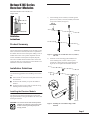
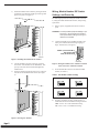
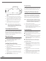
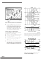
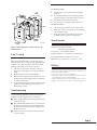
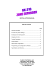
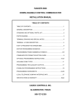
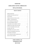
Caddx® Installation Instructions Package
This package includes instructions for the following Caddx products:
■
■
■
■
■
NetworX NX Series Receiver Modules—NX-408 & NX-408-I, NX-416 & NX-416-I, NX-448 & NX-448-I
(Document Number 466-1427)
NX-450 & NX-451 Door/Window Sensor (Document Number 466-1303-CDX)
60-686-43-EUR Door/Window Sensor (Document Number 466-1578)
NX-470 & 60-659-43-EUR 4-Button Keychain Touchpad (Document Number 466-1478)
NX-480 & 60-639-43-EUR Wireless Motion Sensor (Document Number 466-1479)
Caddx Controls, Inc. 1420 North Main Street Gladewater, Texas 75647
Toll Free: 1-800-727-2339 FAX: (903) 845-6811
Caddx is a registered trademark of Caddx Controls, Inc.
For reprints of this package, order part number 466-1486.
Document Number: 466-1486 Rev. E
NetworX NX Series
Receiver Modules
NetworX NX Series Receiver Modules
Document Number: 466-1427 Rev. E
August 1998
1)
After mounting the NX-8 cabinet, install the ground
plane screws, washers, and nuts (included) in the holes
on top of the cabinet (see Figure 1).
TOP OF
ENCLOSURE
9740G15A.DS4
60-732
Installation
Instructions
Product Summary
The NX-Series Receiver Modules (8-zone NX-408, 16-zone
NX-416, and 48-zone NX-448) add wireless capabilities to
the Caddx® NetworX NX-8 control panel. Adding a receiver
module makes NX-8 control panels compatible with NX
wireless transmitters and keychain touchpads (keyfobs).
The receiver modules mount inside the NX-8 cabinet and
require just three wire connections for power and data communications to the NX-8 motherboard.
9740G05A.DS4
Figure 1. Installing the Ground Plane Screws, Washers,
and Nuts
2)
Install the circuit board edge guide standoff in the
lower mounting hole, in either of the two spaces
located just to the left of the NX-8 motherboard (see
Figure 2). Do not tighten the standoff at this time.
Installation Guidelines
Use the following guidelines when installing receiver modules:
■
■
■
Leave at least 10" above the control panel for the module’s antennas.
Avoid areas that are likely to expose the module to
moisture.
Avoid areas with excessive metal or electrical wiring,
including furnace and utility rooms.
Installing the Receiver Module
The following steps describe mounting the circuit board
edge guide standoff, securing the module to the cabinet, and
inserting the antennas.
9740G08A.DS4
CAUTION: You must be free of static electricity before
handling circuit boards. Touch a bare metal
surface or wear a grounding strap to discharge yourself.
Figure 2. Installing the Circuit Board Edge Guide
Standoff
Page 1
NetworX NX Series Receiver Modules
3)
Install the module into the cabinet by turning the standoff sideways, then slide the module up onto the ground
plane screw posts (see Figure 3).
Wiring, Module Number DIP Switch
Settings, and Power Up
The following steps describe wiring the module to the NX8, setting the module number DIP switches, and powering
up the NX-8.
1)
Remove power (if applied) from the NX-8 control
panel.
CAUTION: To avoid possible equipment damage or personal injury, remove power from the NX-8
control panel before making any wiring connections to the module.
2)
Connect the module power and data terminals to the
NX-8 power and data terminals using 22-gauge or
larger, stranded wire (see Figure 5).
POWER + (TO NX-8 AUX PWR +)
GND (TO NX-8 COM)
DATA (TO NX-8 KP DATA)
9740G04A.DS4
Figure 3. Installing the Module into the Cabinet
9740G14A.DS4
4)
5)
Turn the standoff so the slot is facing up, insert the
back corner of the module into the standoff slot, then
press up at the front of the standoff and tighten the
standoff screw.
Insert the antennas through the holes on top of the cabinet and into the module antenna sockets (see Figure
4).
Figure 5. Wiring the Module Power and Data Terminals
to the NX-8 Power and Data Terminals
3)
Set the module DIP switches to the desired module
number (see Table 1).
Table 1. NX Module Number Settings
Module Number 32
ON
1 2
EDG
3 4
Module Number 34
ON
1 2
4)
9740G10A.DS4
Figure 4. Inserting the Antennas
Page 2
EDG
3 4
Module Number 33
ON
1 2
EDG
3 4
Module Number 35
ON
1 2
EDG
3 4
If using a NX-408 or NX-416, set DIP switch 3 to
enable zone blocks for transmitter learning as follows:
OFF = zones 9-16 or 9-24 enabled for learning
ON = zones 1-8 or 1-16 enabled for learning
NetworX NX Series Receiver Modules
5)
Apply power to the NX-8. The middle (red) LED on
the module should start blinking. Table 2 describes the
module’s status based on LED conditions.
Table 2. Module Status Conditions
LED
Module Status
Red-blinking
Normal data communication with
NX-8.
Red-off
No data communication with NX-8.
Check wiring and power source.
Green-blinking
Receiving radio signals from Learn
Mode wireless sensors.
Green-off
No radio signals currently being
received.
Note:
The red LED at the bottom of the module may
emit a dim glow but is not used as an indicator
and can be ignored.
Special Settings for Door/Window
Transmitters and Wireless Smoke Detectors
Use the following guidelines when setting features 3 and 4
for door/window transmitters and wireless smoke detectors.
■
Feature 3—Input Option 1
For door/window transmitters, turn on this feature to
disable the transmitter’s internal reed switches.
For wireless smoke detectors with tamper switches,
turn on this feature to enable the tamper feature.
Note:
■
Feature 3—Input Option 1, must be off (disabled)
when using wireless smoke detectors without
tamper switches.
Feature 4—Input Option 2
For door/window transmitters that use a normally open
external contact, leave this feature off (N/O).
For door/window transmitters that use a normally
closed external contact, turn this feature on (N/C).
Programming
This section describes the following programming steps:
■
■
■
Determine Programming Settings—provides tables to
record wireless transmitter and partition settings.
Enroll the Module—sets up the module to be supervised by the NX-8 control panel.
Program the Module—puts the module into program so
you can program transmitters and enter the settings for
transmitters and partitions.
Determine Transmitter Settings
When programming wireless transmitters into the module,
there are various options and partitions you can set for each
transmitter. These settings appear in segments of each programming location.
Check the desired boxes in the programming worksheet
table (Table 3) on pages 4 through 8 to determine the option
and partition settings for each transmitter zone. This gives
you all the programming information in one place and helps
speed up the programming process.
Note:
The default settings shown for Segments 1 and 2
in Location 1 (Zone 1) apply to all zone locations
1 through 48.
Page 3
NetworX NX Series Receiver Modules
Table 3. Module Programming Worksheet Table
(cont.)
Table 3. Module Programming Worksheet Table
Location
Location
Segment 2
0 (Supervision)
1 - Normal ______hrs.
(0 - 255 hours;
default = 24 hours)
Fire ______hrs.
(0 - 255 hours;
default = 4 hours)
1 (Zone 1)
Assigned to
module
#_____.
1 - Enable sensor ❏
(default = off)
2 - Supervised ❏
(default = on)
3 - Input option 1 ❏
(default = off)
4 - Input option 2 ❏
(default = off)
5 - Xmitter not lost* ❏
(default = off)
6 - Low battery* ❏
(default = off)
7 - Last signal good* ❏
(default = off)
8 - Not used*
(*Read only location)
Partition 1 keyfob ❏
(default = on)
Partition 2 keyfob ❏
(default = off)
Partition 3 keyfob ❏
(default = off)
Partition 4 keyfob ❏
(default = off)
Partition 5 keyfob ❏
(default = off)
Partition 6 keyfob ❏
(default = off)
Partition 7 keyfob ❏
(default = off)
Partition 8 keyfob ❏
(default = off)
1 - Enable sensor ❏
2 - Supervised ❏
3 - Input option 1 ❏
4 - Input option 2 ❏
5 - Xmitter not lost* ❏
6 - Low battery* ❏
7 - Last signal good* ❏
8 - Not used*
(*Read only location)
Partition 1 keyfob ❏
Partition 2 keyfob ❏
Partition 3 keyfob ❏
Partition 4 keyfob ❏
Partition 5 keyfob ❏
Partition 6 keyfob ❏
Partition 7 keyfob ❏
Partition 8 keyfob ❏
2 (Zone 2)
Assigned to
module
#_____.
3 (Zone 3)
Assigned to
module
#_____.
4 (Zone 4)
Assigned to
module
#_____.
Page 4
Segment 1
Segment 1
Segment 2
5 (Zone 5)
Assigned to
module
#_____.
1 - Enable sensor ❏
2 - Supervised ❏
3 - Input option 1 ❏
4 - Input option 2 ❏
5 - Xmitter not lost* ❏
6 - Low battery* ❏
7 - Last signal good* ❏
8 - Not used*
(*Read only location)
Partition 1 keyfob ❏
Partition 2 keyfob ❏
Partition 3 keyfob ❏
Partition 4 keyfob ❏
Partition 5 keyfob ❏
Partition 6 keyfob ❏
Partition 7 keyfob ❏
Partition 8 keyfob ❏
6 (Zone 6)
Assigned to
module
#_____.
1 - Enable sensor ❏
2 - Supervised ❏
3 - Input option 1 ❏
4 - Input option 2 ❏
5 - Xmitter not lost* ❏
6 - Low battery* ❏
7 - Last signal good* ❏
8 - Not used*
(*Read only location)
Partition 1 keyfob ❏
Partition 2 keyfob ❏
Partition 3 keyfob ❏
Partition 4 keyfob ❏
Partition 5 keyfob ❏
Partition 6 keyfob ❏
Partition 7 keyfob ❏
Partition 8 keyfob ❏
7 (Zone 7)
Assigned to
module
#_____.
1 - Enable sensor ❏
2 - Supervised ❏
3 - Input option 1 ❏
4 - Input option 2 ❏
5 - Xmitter not lost* ❏
6 - Low battery* ❏
7 - Last signal good* ❏
8 - Not used*
(*Read only location)
Partition 1 keyfob ❏
Partition 2 keyfob ❏
Partition 3 keyfob ❏
Partition 4 keyfob ❏
Partition 5 keyfob ❏
Partition 6 keyfob ❏
Partition 7 keyfob ❏
Partition 8 keyfob ❏
8 (Zone 8)
Assigned to
module
#_____.
1 - Enable sensor ❏
2 - Supervised ❏
3 - Input option 1 ❏
4 - Input option 2 ❏
5 - Xmitter not lost* ❏
6 - Low battery* ❏
7 - Last signal good* ❏
8 - Not used*
(*Read only location)
Partition 1 keyfob ❏
Partition 2 keyfob ❏
Partition 3 keyfob ❏
Partition 4 keyfob ❏
Partition 5 keyfob ❏
Partition 6 keyfob ❏
Partition 7 keyfob ❏
Partition 8 keyfob ❏
9 (Zone 9)
Assigned to
module
#_____.
1 - Enable sensor ❏
2 - Supervised ❏
3 - Input option 1 ❏
4 - Input option 2 ❏
5 - Xmitter not lost* ❏
6 - Low battery* ❏
7 - Last signal good* ❏
8 - Not used*
(*Read only location)
Partition 1 keyfob ❏
Partition 2 keyfob ❏
Partition 3 keyfob ❏
Partition 4 keyfob ❏
Partition 5 keyfob ❏
Partition 6 keyfob ❏
Partition 7 keyfob ❏
Partition 8 keyfob ❏
NetworX NX Series Receiver Modules
Table 3. Module Programming Worksheet Table
(cont.)
Table 3. Module Programming Worksheet Table
(cont.)
Location
Segment 1
Segment 2
Location
Segment 1
Segment 2
10 (Zone 10)
Assigned to
module
#_____.
1 - Enable sensor ❏
2 - Supervised ❏
3 - Input option 1 ❏
4 - Input option 2 ❏
5 - Xmitter not lost* ❏
6 - Low battery* ❏
7 - Last signal good* ❏
8 - Not used*
(*Read only location)
Partition 1 keyfob ❏
Partition 2 keyfob ❏
Partition 3 keyfob ❏
Partition 4 keyfob ❏
Partition 5 keyfob ❏
Partition 6 keyfob ❏
Partition 7 keyfob ❏
Partition 8 keyfob ❏
15 (Zone 15)
Assigned to
module
#_____.
1 - Enable sensor ❏
2 - Supervised ❏
3 - Input option 1 ❏
4 - Input option 2 ❏
5 - Xmitter not lost* ❏
6 - Low battery* ❏
7 - Last signal good* ❏
8 - Not used*
(*Read only location)
Partition 1 keyfob ❏
Partition 2 keyfob ❏
Partition 3 keyfob ❏
Partition 4 keyfob ❏
Partition 5 keyfob ❏
Partition 6 keyfob ❏
Partition 7 keyfob ❏
Partition 8 keyfob ❏
11 (Zone 11)
Assigned to
module
#_____.
1 - Enable sensor ❏
2 - Supervised ❏
3 - Input option 1 ❏
4 - Input option 2 ❏
5 - Xmitter not lost* ❏
6 - Low battery* ❏
7 - Last signal good* ❏
8 - Not used*
(*Read only location)
Partition 1 keyfob ❏
Partition 2 keyfob ❏
Partition 3 keyfob ❏
Partition 4 keyfob ❏
Partition 5 keyfob ❏
Partition 6 keyfob ❏
Partition 7 keyfob ❏
Partition 8 keyfob ❏
16 (Zone 16)
Assigned to
module
#_____.
1 - Enable sensor ❏
2 - Supervised ❏
3 - Input option 1 ❏
4 - Input option 2 ❏
5 - Xmitter not lost* ❏
6 - Low battery* ❏
7 - Last signal good* ❏
8 - Not used*
(*Read only location)
Partition 1 keyfob ❏
Partition 2 keyfob ❏
Partition 3 keyfob ❏
Partition 4 keyfob ❏
Partition 5 keyfob ❏
Partition 6 keyfob ❏
Partition 7 keyfob ❏
Partition 8 keyfob ❏
12 (Zone 12)
Assigned to
module
#_____.
1 - Enable sensor ❏
2 - Supervised ❏
3 - Input option 1 ❏
4 - Input option 2 ❏
5 - Xmitter not lost* ❏
6 - Low battery* ❏
7 - Last signal good* ❏
8 - Not used*
(*Read only location)
Partition 1 keyfob ❏
Partition 2 keyfob ❏
Partition 3 keyfob ❏
Partition 4 keyfob ❏
Partition 5 keyfob ❏
Partition 6 keyfob ❏
Partition 7 keyfob ❏
Partition 8 keyfob ❏
17 (Zone 17)
Assigned to
module
#_____.
1 - Enable sensor ❏
2 - Supervised ❏
3 - Input option 1 ❏
4 - Input option 2 ❏
5 - Xmitter not lost* ❏
6 - Low battery* ❏
7 - Last signal good* ❏
8 - Not used*
(*Read only location)
Partition 1 keyfob ❏
Partition 2 keyfob ❏
Partition 3 keyfob ❏
Partition 4 keyfob ❏
Partition 5 keyfob ❏
Partition 6 keyfob ❏
Partition 7 keyfob ❏
Partition 8 keyfob ❏
13 (Zone 13)
Assigned to
module
#_____.
1 - Enable sensor ❏
2 - Supervised ❏
3 - Input option 1 ❏
4 - Input option 2 ❏
5 - Xmitter not lost* ❏
6 - Low battery* ❏
7 - Last signal good* ❏
8 - Not used*
(*Read only location)
Partition 1 keyfob ❏
Partition 2 keyfob ❏
Partition 3 keyfob ❏
Partition 4 keyfob ❏
Partition 5 keyfob ❏
Partition 6 keyfob ❏
Partition 7 keyfob ❏
Partition 8 keyfob ❏
18 (Zone 18)
Assigned to
module
#_____.
1 - Enable sensor ❏
2 - Supervised ❏
3 - Input option 1 ❏
4 - Input option 2 ❏
5 - Xmitter not lost* ❏
6 - Low battery* ❏
7 - Last signal good* ❏
8 - Not used*
(*Read only location)
Partition 1 keyfob ❏
Partition 2 keyfob ❏
Partition 3 keyfob ❏
Partition 4 keyfob ❏
Partition 5 keyfob ❏
Partition 6 keyfob ❏
Partition 7 keyfob ❏
Partition 8 keyfob ❏
14 (Zone 14)
Assigned to
module
#_____.
1 - Enable sensor ❏
2 - Supervised ❏
3 - Input option 1 ❏
4 - Input option 2 ❏
5 - Xmitter not lost* ❏
6 - Low battery* ❏
7 - Last signal good* ❏
8 - Not used*
(*Read only location)
Partition 1 keyfob ❏
Partition 2 keyfob ❏
Partition 3 keyfob ❏
Partition 4 keyfob ❏
Partition 5 keyfob ❏
Partition 6 keyfob ❏
Partition 7 keyfob ❏
Partition 8 keyfob ❏
19 (Zone 19)
Assigned to
module
#_____.
1 - Enable sensor ❏
2 - Supervised ❏
3 - Input option 1 ❏
4 - Input option 2 ❏
5 - Xmitter not lost* ❏
6 - Low battery* ❏
7 - Last signal good* ❏
8 - Not used*
(*Read only location)
Partition 1 keyfob ❏
Partition 2 keyfob ❏
Partition 3 keyfob ❏
Partition 4 keyfob ❏
Partition 5 keyfob ❏
Partition 6 keyfob ❏
Partition 7 keyfob ❏
Partition 8 keyfob ❏
Page 5
NetworX NX Series Receiver Modules
Table 3. Module Programming Worksheet Table
(cont.)
Page 6
Table 3. Module Programming Worksheet Table
(cont.)
Location
Segment 1
Segment 2
Location
Segment 1
Segment 2
20 (Zone 20)
Assigned to
module
#_____.
1 - Enable sensor ❏
2 - Supervised ❏
3 - Input option 1 ❏
4 - Input option 2 ❏
5 - Xmitter not lost* ❏
6 - Low battery* ❏
7 - Last signal good* ❏
8 - Not used*
(*Read only location)
Partition 1 keyfob ❏
Partition 2 keyfob ❏
Partition 3 keyfob ❏
Partition 4 keyfob ❏
Partition 5 keyfob ❏
Partition 6 keyfob ❏
Partition 7 keyfob ❏
Partition 8 keyfob ❏
25 (Zone 25)
Assigned to
module
#_____.
1 - Enable sensor ❏
2 - Supervised ❏
3 - Input option 1 ❏
4 - Input option 2 ❏
5 - Xmitter not lost* ❏
6 - Low battery* ❏
7 - Last signal good* ❏
8 - Not used*
(*Read only location)
Partition 1 keyfob ❏
Partition 2 keyfob ❏
Partition 3 keyfob ❏
Partition 4 keyfob ❏
Partition 5 keyfob ❏
Partition 6 keyfob ❏
Partition 7 keyfob ❏
Partition 8 keyfob ❏
21 (Zone 21)
Assigned to
module
#_____.
1 - Enable sensor ❏
2 - Supervised ❏
3 - Input option 1 ❏
4 - Input option 2 ❏
5 - Xmitter not lost* ❏
6 - Low battery* ❏
7 - Last signal good* ❏
8 - Not used*
(*Read only location)
Partition 1 keyfob ❏
Partition 2 keyfob ❏
Partition 3 keyfob ❏
Partition 4 keyfob ❏
Partition 5 keyfob ❏
Partition 6 keyfob ❏
Partition 7 keyfob ❏
Partition 8 keyfob ❏
26 (Zone 26)
Assigned to
module
#_____.
1 - Enable sensor ❏
2 - Supervised ❏
3 - Input option 1 ❏
4 - Input option 2 ❏
5 - Xmitter not lost* ❏
6 - Low battery* ❏
7 - Last signal good* ❏
8 - Not used*
(*Read only location)
Partition 1 keyfob ❏
Partition 2 keyfob ❏
Partition 3 keyfob ❏
Partition 4 keyfob ❏
Partition 5 keyfob ❏
Partition 6 keyfob ❏
Partition 7 keyfob ❏
Partition 8 keyfob ❏
22 (Zone 22)
Assigned to
module
#_____.
1 - Enable sensor ❏
2 - Supervised ❏
3 - Input option 1 ❏
4 - Input option 2 ❏
5 - Xmitter not lost* ❏
6 - Low battery* ❏
7 - Last signal good* ❏
8 - Not used*
(*Read only location)
Partition 1 keyfob ❏
Partition 2 keyfob ❏
Partition 3 keyfob ❏
Partition 4 keyfob ❏
Partition 5 keyfob ❏
Partition 6 keyfob ❏
Partition 7 keyfob ❏
Partition 8 keyfob ❏
27 (Zone 27)
Assigned to
module
#_____.
1 - Enable sensor ❏
2 - Supervised ❏
3 - Input option 1 ❏
4 - Input option 2 ❏
5 - Xmitter not lost* ❏
6 - Low battery* ❏
7 - Last signal good* ❏
8 - Not used*
(*Read only location)
Partition 1 keyfob ❏
Partition 2 keyfob ❏
Partition 3 keyfob ❏
Partition 4 keyfob ❏
Partition 5 keyfob ❏
Partition 6 keyfob ❏
Partition 7 keyfob ❏
Partition 8 keyfob ❏
23 (Zone 23)
Assigned to
module
#_____.
1 - Enable sensor ❏
2 - Supervised ❏
3 - Input option 1 ❏
4 - Input option 2 ❏
5 - Xmitter not lost* ❏
6 - Low battery* ❏
7 - Last signal good* ❏
8 - Not used*
(*Read only location)
Partition 1 keyfob ❏
Partition 2 keyfob ❏
Partition 3 keyfob ❏
Partition 4 keyfob ❏
Partition 5 keyfob ❏
Partition 6 keyfob ❏
Partition 7 keyfob ❏
Partition 8 keyfob ❏
28 (Zone 28)
Assigned to
module
#_____.
1 - Enable sensor ❏
2 - Supervised ❏
3 - Input option 1 ❏
4 - Input option 2 ❏
5 - Xmitter not lost* ❏
6 - Low battery* ❏
7 - Last signal good* ❏
8 - Not used*
(*Read only location)
Partition 1 keyfob ❏
Partition 2 keyfob ❏
Partition 3 keyfob ❏
Partition 4 keyfob ❏
Partition 5 keyfob ❏
Partition 6 keyfob ❏
Partition 7 keyfob ❏
Partition 8 keyfob ❏
24 (Zone 24)
Assigned to
module
#_____.
1 - Enable sensor ❏
2 - Supervised ❏
3 - Input option 1 ❏
4 - Input option 2 ❏
5 - Xmitter not lost* ❏
6 - Low battery* ❏
7 - Last signal good* ❏
8 - Not used*
(*Read only location)
Partition 1 keyfob ❏
Partition 2 keyfob ❏
Partition 3 keyfob ❏
Partition 4 keyfob ❏
Partition 5 keyfob ❏
Partition 6 keyfob ❏
Partition 7 keyfob ❏
Partition 8 keyfob ❏
29 (Zone 29)
Assigned to
module
#_____.
1 - Enable sensor ❏
2 - Supervised ❏
3 - Input option 1 ❏
4 - Input option 2 ❏
5 - Xmitter not lost* ❏
6 - Low battery* ❏
7 - Last signal good* ❏
8 - Not used*
(*Read only location)
Partition 1 keyfob ❏
Partition 2 keyfob ❏
Partition 3 keyfob ❏
Partition 4 keyfob ❏
Partition 5 keyfob ❏
Partition 6 keyfob ❏
Partition 7 keyfob ❏
Partition 8 keyfob ❏
NetworX NX Series Receiver Modules
Table 3. Module Programming Worksheet Table
(cont.)
Table 3. Module Programming Worksheet Table
(cont.)
Location
Segment 1
Segment 2
Location
Segment 1
Segment 2
30 (Zone 30)
Assigned to
module
#_____.
1 - Enable sensor ❏
2 - Supervised ❏
3 - Input option 1 ❏
4 - Input option 2 ❏
5 - Xmitter not lost* ❏
6 - Low battery* ❏
7 - Last signal good* ❏
8 - Not used*
(*Read only location)
Partition 1 keyfob ❏
Partition 2 keyfob ❏
Partition 3 keyfob ❏
Partition 4 keyfob ❏
Partition 5 keyfob ❏
Partition 6 keyfob ❏
Partition 7 keyfob ❏
Partition 8 keyfob ❏
35 (Zone 35)
Assigned to
module
#_____.
1 - Enable sensor ❏
2 - Supervised ❏
3 - Input option 1 ❏
4 - Input option 2 ❏
5 - Xmitter not lost* ❏
6 - Low battery* ❏
7 - Last signal good* ❏
8 - Not used*
(*Read only location)
Partition 1 keyfob ❏
Partition 2 keyfob ❏
Partition 3 keyfob ❏
Partition 4 keyfob ❏
Partition 5 keyfob ❏
Partition 6 keyfob ❏
Partition 7 keyfob ❏
Partition 8 keyfob ❏
31 (Zone 31)
Assigned to
module
#_____.
1 - Enable sensor ❏
2 - Supervised ❏
3 - Input option 1 ❏
4 - Input option 2 ❏
5 - Xmitter not lost* ❏
6 - Low battery* ❏
7 - Last signal good* ❏
8 - Not used*
(*Read only location)
Partition 1 keyfob ❏
Partition 2 keyfob ❏
Partition 3 keyfob ❏
Partition 4 keyfob ❏
Partition 5 keyfob ❏
Partition 6 keyfob ❏
Partition 7 keyfob ❏
Partition 8 keyfob ❏
36 (Zone 36)
Assigned to
module
#_____.
1 - Enable sensor ❏
2 - Supervised ❏
3 - Input option 1 ❏
4 - Input option 2 ❏
5 - Xmitter not lost* ❏
6 - Low battery* ❏
7 - Last signal good* ❏
8 - Not used*
(*Read only location)
Partition 1 keyfob ❏
Partition 2 keyfob ❏
Partition 3 keyfob ❏
Partition 4 keyfob ❏
Partition 5 keyfob ❏
Partition 6 keyfob ❏
Partition 7 keyfob ❏
Partition 8 keyfob ❏
32 (Zone 32)
Assigned to
module
#_____.
1 - Enable sensor ❏
2 - Supervised ❏
3 - Input option 1 ❏
4 - Input option 2 ❏
5 - Xmitter not lost* ❏
6 - Low battery* ❏
7 - Last signal good* ❏
8 - Not used*
(*Read only location)
Partition 1 keyfob ❏
Partition 2 keyfob ❏
Partition 3 keyfob ❏
Partition 4 keyfob ❏
Partition 5 keyfob ❏
Partition 6 keyfob ❏
Partition 7 keyfob ❏
Partition 8 keyfob ❏
37 (Zone 37)
Assigned to
module
#_____.
1 - Enable sensor ❏
2 - Supervised ❏
3 - Input option 1 ❏
4 - Input option 2 ❏
5 - Xmitter not lost* ❏
6 - Low battery* ❏
7 - Last signal good* ❏
8 - Not used*
(*Read only location)
Partition 1 keyfob ❏
Partition 2 keyfob ❏
Partition 3 keyfob ❏
Partition 4 keyfob ❏
Partition 5 keyfob ❏
Partition 6 keyfob ❏
Partition 7 keyfob ❏
Partition 8 keyfob ❏
33 (Zone 33)
Assigned to
module
#_____.
1 - Enable sensor ❏
2 - Supervised ❏
3 - Input option 1 ❏
4 - Input option 2 ❏
5 - Xmitter not lost* ❏
6 - Low battery* ❏
7 - Last signal good* ❏
8 - Not used*
(*Read only location)
Partition 1 keyfob ❏
Partition 2 keyfob ❏
Partition 3 keyfob ❏
Partition 4 keyfob ❏
Partition 5 keyfob ❏
Partition 6 keyfob ❏
Partition 7 keyfob ❏
Partition 8 keyfob ❏
38 (Zone 38)
Assigned to
module
#_____.
1 - Enable sensor ❏
2 - Supervised ❏
3 - Input option 1 ❏
4 - Input option 2 ❏
5 - Xmitter not lost* ❏
6 - Low battery* ❏
7 - Last signal good* ❏
8 - Not used*
(*Read only location)
Partition 1 keyfob ❏
Partition 2 keyfob ❏
Partition 3 keyfob ❏
Partition 4 keyfob ❏
Partition 5 keyfob ❏
Partition 6 keyfob ❏
Partition 7 keyfob ❏
Partition 8 keyfob ❏
34 (Zone 34)
Assigned to
module
#_____.
1 - Enable sensor ❏
2 - Supervised ❏
3 - Input option 1 ❏
4 - Input option 2 ❏
5 - Xmitter not lost* ❏
6 - Low battery* ❏
7 - Last signal good* ❏
8 - Not used*
(*Read only location)
Partition 1 keyfob ❏
Partition 2 keyfob ❏
Partition 3 keyfob ❏
Partition 4 keyfob ❏
Partition 5 keyfob ❏
Partition 6 keyfob ❏
Partition 7 keyfob ❏
Partition 8 keyfob ❏
39 (Zone 39)
Assigned to
module
#_____.
1 - Enable sensor ❏
2 - Supervised ❏
3 - Input option 1 ❏
4 - Input option 2 ❏
5 - Xmitter not lost* ❏
6 - Low battery* ❏
7 - Last signal good* ❏
8 - Not used*
(*Read only location)
Partition 1 keyfob ❏
Partition 2 keyfob ❏
Partition 3 keyfob ❏
Partition 4 keyfob ❏
Partition 5 keyfob ❏
Partition 6 keyfob ❏
Partition 7 keyfob ❏
Partition 8 keyfob ❏
Page 7
NetworX NX Series Receiver Modules
Table 3. Module Programming Worksheet Table
(cont.)
Page 8
Table 3. Module Programming Worksheet Table
(cont.)
Location
Segment 1
Segment 2
Location
Segment 1
Segment 2
40 (Zone 40)
Assigned to
module
#_____.
1 - Enable sensor ❏
2 - Supervised ❏
3 - Input option 1 ❏
4 - Input option 2 ❏
5 - Xmitter not lost* ❏
6 - Low battery* ❏
7 - Last signal good* ❏
8 - Not used*
(*Read only location)
Partition 1 keyfob ❏
Partition 2 keyfob ❏
Partition 3 keyfob ❏
Partition 4 keyfob ❏
Partition 5 keyfob ❏
Partition 6 keyfob ❏
Partition 7 keyfob ❏
Partition 8 keyfob ❏
45 (Zone 45)
Assigned to
module
#_____.
1 - Enable sensor ❏
2 - Supervised ❏
3 - Input option 1 ❏
4 - Input option 2 ❏
5 - Xmitter not lost* ❏
6 - Low battery* ❏
7 - Last signal good* ❏
8 - Not used*
(*Read only location)
Partition 1 keyfob ❏
Partition 2 keyfob ❏
Partition 3 keyfob ❏
Partition 4 keyfob ❏
Partition 5 keyfob ❏
Partition 6 keyfob ❏
Partition 7 keyfob ❏
Partition 8 keyfob ❏
41 (Zone 41)
Assigned to
module
#_____.
1 - Enable sensor ❏
2 - Supervised ❏
3 - Input option 1 ❏
4 - Input option 2 ❏
5 - Xmitter not lost* ❏
6 - Low battery* ❏
7 - Last signal good* ❏
8 - Not used*
(*Read only location)
Partition 1 keyfob ❏
Partition 2 keyfob ❏
Partition 3 keyfob ❏
Partition 4 keyfob ❏
Partition 5 keyfob ❏
Partition 6 keyfob ❏
Partition 7 keyfob ❏
Partition 8 keyfob ❏
46 (Zone 46)
Assigned to
module
#_____.
1 - Enable sensor ❏
2 - Supervised ❏
3 - Input option 1 ❏
4 - Input option 2 ❏
5 - Xmitter not lost* ❏
6 - Low battery* ❏
7 - Last signal good* ❏
8 - Not used*
(*Read only location)
Partition 1 keyfob ❏
Partition 2 keyfob ❏
Partition 3 keyfob ❏
Partition 4 keyfob ❏
Partition 5 keyfob ❏
Partition 6 keyfob ❏
Partition 7 keyfob ❏
Partition 8 keyfob ❏
42 (Zone 42)
Assigned to
module
#_____.
1 - Enable sensor ❏
2 - Supervised ❏
3 - Input option 1 ❏
4 - Input option 2 ❏
5 - Xmitter not lost* ❏
6 - Low battery* ❏
7 - Last signal good* ❏
8 - Not used*
(*Read only location)
Partition 1 keyfob ❏
Partition 2 keyfob ❏
Partition 3 keyfob ❏
Partition 4 keyfob ❏
Partition 5 keyfob ❏
Partition 6 keyfob ❏
Partition 7 keyfob ❏
Partition 8 keyfob ❏
47 (Zone 47)
Assigned to
module
#_____.
1 - Enable sensor ❏
2 - Supervised ❏
3 - Input option 1 ❏
4 - Input option 2 ❏
5 - Xmitter not lost* ❏
6 - Low battery* ❏
7 - Last signal good* ❏
8 - Not used*
(*Read only location)
Partition 1 keyfob ❏
Partition 2 keyfob ❏
Partition 3 keyfob ❏
Partition 4 keyfob ❏
Partition 5 keyfob ❏
Partition 6 keyfob ❏
Partition 7 keyfob ❏
Partition 8 keyfob ❏
43 (Zone 43)
Assigned to
module
#_____.
1 - Enable sensor ❏
2 - Supervised ❏
3 - Input option 1 ❏
4 - Input option 2 ❏
5 - Xmitter not lost* ❏
6 - Low battery* ❏
7 - Last signal good* ❏
8 - Not used*
(*Read only location)
Partition 1 keyfob ❏
Partition 2 keyfob ❏
Partition 3 keyfob ❏
Partition 4 keyfob ❏
Partition 5 keyfob ❏
Partition 6 keyfob ❏
Partition 7 keyfob ❏
Partition 8 keyfob ❏
48 (Zone 48)
Assigned to
module
#_____.
1 - Enable sensor ❏
2 - Supervised ❏
3 - Input option 1 ❏
4 - Input option 2 ❏
5 - Xmitter not lost* ❏
6 - Low battery* ❏
7 - Last signal good* ❏
8 - Not used*
(*Read only location)
Partition 1 keyfob ❏
Partition 2 keyfob ❏
Partition 3 keyfob ❏
Partition 4 keyfob ❏
Partition 5 keyfob ❏
Partition 6 keyfob ❏
Partition 7 keyfob ❏
Partition 8 keyfob ❏
44 (Zone 44)
Assigned to
module
#_____.
1 - Enable sensor ❏
2 - Supervised ❏
3 - Input option 1 ❏
4 - Input option 2 ❏
5 - Xmitter not lost* ❏
6 - Low battery* ❏
7 - Last signal good* ❏
8 - Not used*
(*Read only location)
Partition 1 keyfob ❏
Partition 2 keyfob ❏
Partition 3 keyfob ❏
Partition 4 keyfob ❏
Partition 5 keyfob ❏
Partition 6 keyfob ❏
Partition 7 keyfob ❏
Partition 8 keyfob ❏
49 (Transmitter to be
programmed)
None
None
NetworX NX Series Receiver Modules
trol panel is enrolling the module. After about 12 seconds, the service LED should turn off.
Table 3. Module Programming Worksheet Table
(cont.)
Location
50 (All
default off)
51 (Default
= 0)
Segment 1
Segment 2
1 - Keyfob user ID ❏
(off = all keyfobs
report as user 99;
on = keyfob reports
as its learned zone)
2 - Enable jam detect ❏
3 - Enable antenna
tamper (Only
selectable on International versions,
reports as box
tamper) ❏
4 - Enable auto
advance to next
zone number ❏
5 - Enable partition 1
audible programming beeps ❏
6-8 Not used
Starting zone number
for receiver
0 = 1* (default) ❏
1=9❏
2 = 17 ❏
3 = 25 ❏
4 = 33 ❏
5 = 41 ❏
(* When set to 0, the
starting zone number
is determined by DIP
switch 3 setting.)
Enroll the Module
The following steps describe how to enroll and program the
module to be supervised by the NX-8.
1)
2)
3)
4)
5)
With power applied and the system disarmed, enter [✻]
[8] at the keypad. The five function lights should start
flashing.
Enter the “Go To Program Code” (factory default is 9 7
1 3). The service light should flash and the five function lights should change from flashing to on steady.
Enter [0] [#], where [0] is the NX-8 control panel number and [#] is the entry key. The Armed LED should
turn on, indicating the control panel is waiting for a
programming location entry.
Enter [9] [1] [5] [#] to enroll the module for supervision. The keypad sounder should beep three times indicating the NX-8 has accepted the enrolling request.
Exit program mode by entering [EXIT] [EXIT]. The
Service LED on the NX-8 turns on, indicating the con-
Program the Module
The following steps describe how to get the module into
program mode, load factory defaults if installing a new system, and program transmitters into memory.
Programming Guidelines
■
■
■
When a transmitter is learned into memory, the module
claims a block of eight zones around that number (1-8,
9-16, 17-24, etc.). For example, learning a transmitter
into zone 13 automatically claims the zone block of 9
through 16. Only wireless transmitters can now be
assigned to these zones.
Do not learn wireless transmitters into a zone block
claimed by a hardwire expander or the panel.
If two modules are installed, they cannot share the
same zone block. For example, wireless transmitters
learned into zones 11 and 12 must reside in one module.
Fill in Table 4 to help keep track of zone block module
assignments. Be sure to circle the module type; RM =
receiver module, HE = hardwire expander, P = panel.
Table 4. Zone Block Module Assignments
Zone Block
Assigned To Module
1-8
RM HE P #______
9 - 16
RM HE P #______
17 - 24
RM HE P #______
25 - 32
RM HE P #______
33 - 40
RM HE P #______
41 - 48
RM HE P #______
To program the module:
1)
2)
3)
4)
Enter [✻] [8] at the keypad. The five function lights
should start flashing.
Enter the “Go To Program Code” (factory default is 9 7
1 3). The service light should flash and the five function lights should change from flashing to on steady.
Enter [XX] [#], where [XX] is the DIP switch setting
module number and [#] is the entry key. The Armed
LED should turn on, indicating the control panel is
waiting for a programming location entry.
For new installations, enter [9] [1] [0] [#] to load factory defaults and clear any unwanted information in
memory before any further programming.
Page 9
NetworX NX Series Receiver Modules
5)
6)
Enter [4] [9] [#] to enter the sensor learning location.
The Ready LED should turn on and the Armed LED
should turn off.
Enter [XX] [✻], where [XX] is a zone number (1
through 48) and [✻] is the entry key.
Note:
Three beeps from the keypad indicates an entry
error. This occurs if you enter a transmitter number that is not within the module’s zone block or if
you try learning a sensor that is already learned
into the module.
If you change your mind about your entry, you
can terminate programming by entering [4] [9] [#]
[0] [✻]. Then, start again from step 5.
7)
Trip the desired transmitter (within 250 seconds) as
described in Table 5. Listen for the ‘ding dong’ for
confirmation.
Table 5. Tripping Transmitters for Learning
Transmitter
Action
Door/Window, Shock,
Glass Guard, Freeze
Activate tamper switch by
removing cover.
Door/Window with External Contact
Activate tamper switch by
removing cover. (Note:
Feature 3—Input Option
1, must be on.)
Recessed Door/Window
Activate tamper switch by
removing circuit board
until tamper switch is
exposed.
Micro Door/Window
Slide the battery about
half-way out of the battery
holder, then back.
PIR
Activate tamper switch by
removing back plate from
PIR.
Smoke Detector
Press and hold the test button.
Heat Detector
Press, then release the
tamper switch.
Fire Pull
Activate tamper switch by
removing sensor cover.
Single Button Panic
Press and hold the button.
Dual Button Panic
Press and hold both buttons together.
Table 5. Tripping Transmitters for Learning
Transmitter
Keyfobs
Press and hold the arm and
disarm buttons together.
Repeater
Press, then release the
tamper switch.
8)
9)
Program remaining transmitters by repeating steps 5-7.
Exit program mode by entering [EXIT] [EXIT].
Program Transmitter and Partition
Settings
This section describes programming guidelines, how to
change the supervision windows, and program the transmitter and partition settings using the information you entered
in the Table 3 programming worksheets.
Changing the Transmitter Supervision
Windows
Note:
For UL Listed installations, the normal supervision window must be set to 24 hours and the fire
supervision window must be set to 4 hours.
CAUTION: Do not set the normal or fire supervision windows to 1 hour. This causes false trouble
reports from all learned wireless transmitters.
1)
2)
3)
4)
5)
Enter [✻] [8] at the keypad. The five function lights
should start flashing.
Enter the “Go To Program Code” (factory default is 9 7
1 3). The service light should flash and the five function lights should change from flashing to on steady.
Enter [XX] [#], where [XX] is the DIP switch setting
module number and [#] is the entry key. The Armed
LED should turn on, indicating the control panel is
waiting for a programming location entry.
Enter [0] [#] to enter location 0, segment 1.
Enter the new normal supervision time (0 - 255).
Note:
6)
7)
Choosing 0 sets the normal supervision window
to 256 hours.
Press [✻] to save any changes and automatically enter
segment 2.
Enter the new fire supervision time (0 - 255).
Note:
Page 10
Action
Choosing 0 sets the fire supervision window to
256 hours.
NetworX NX Series Receiver Modules
8)
Press [✻] to save any changes. The panel is now waiting for the next location entry.
Note:
9)
Pressing [#] does not save changes to the current segment, but does save changes made in
previous segments.
Enter [EXIT] [EXIT] when all changes are completed.
Programming Transmitter and Partition
Settings
1)
Enter [✻] [8] at the keypad. The five function lights
should start flashing.
2) Enter the “Go To Program Code” (factory default is 9 7
1 3). The service light should flash and the five function lights should change from flashing to on steady.
3) Enter [XX] [#], where [XX] is the DIP switch setting
module number and [#] is the entry key. The Armed
LED should turn on, indicating the control panel is
waiting for a programming location entry.
4) Enter [XX] [#] to enter a location. For example, enter
[1] [#] to enter location 1, segment 1. The Armed LED
should turn on and the zone LEDs display the binary
data for the current settings.
or-- Enter [1] [#] [✻] to enter location 1, segment 2.
5) Enter [X] [✻], where [X] is the setting number (1 - 8)
from Table 5 that corresponds to the desired feature or
partition setting number and [✻] is the entry key. The
keypad displays the settings for that location and segment.
6) Press the keypad button that corresponds to the feature
number you want changed. Lights corresponding to the
feature number turn on or off each time the button is
pressed. Lights that turn on indicate the feature is on,
lights that turn off indicate the feature is off.
For example, turn on transmitter features 1 (Transmitter Enabled) and 3 (Input Option 1) by pressing [1] [3].
The 1 and 3 LEDs turn on to indicate the features are
turned on and the Ready LED flashes to indicate the
change request.
7) Press [✻] to enter the changes and automatically
advance to segment 2.
Note:
8)
Pressing [#] does not save changes to the current segment, but does save changes made in
previous segments. Repeat steps 4 - 7 to reenter and make changes to a location and segment.
Press the keypad button that corresponds to the partition number you want changed. Lights corresponding
to the partition number turn on or off each time the button is pressed. Lights that turn on indicate the keyfob is
active in that partition, lights that turn off indicate the
keyfob is inactive.
9)
Repeat steps 4 - 8 to continue programming transmitter
partition settings.
10) Enter [EXIT] [EXIT] when finished.
Deleting Transmitters
The following steps describe how to delete transmitters from
the module.
This procedure makes the module ignore a transmitter but
does not remove transmitter identification from the module’s memory. The transmitter can be reactivated later or a
new one can be learned into the zone.
1)
Enter [✻] [8] at the keypad. The five function lights
should start flashing.
2) Enter the “Go To Program Code” (factory default is 9 7
1 3). The service light should flash and the five function lights should change from flashing to on steady.
3) Enter [XX] [#], where [XX] is the DIP switch setting
module number and [#] is the entry key. The Armed
LED should turn on, indicating the control panel is
waiting for a programming location entry.
4) Enter [XX] [#] to enter the zone location to be deleted.
The Armed LED should turn on and the zone LEDs
display the binary data for the current settings.
5) Change transmitter feature 1 (Transmitter Enabled) by
pressing [1]. The 1 LED turns off to indicate the feature
change and the Ready LED flashes to indicate the
change request.
6) Enter [✻] [#]. The Ready LED stops flashing, indicating the new settings are stored in memory and the system automatically exits from that location.
7) Continue deleting transmitters by entering the desired
locations and segments in steps 4 through 6.
or-- Enter [9] [1] [0] [#] to delete all transmitters and load
factory defaults.
8) Enter [EXIT] [EXIT] when finished.
Testing Wireless Transmitters
Test all transmitters to verify correct programming and
operation, using the steps below.
1)
2)
3)
4)
Trip a transmitter (open a door, walk in front of a PIR,
etc.).
Enter [✻] [8] at the keypad. The five function lights
should start flashing.
Enter the “Go To Program Code” (factory default is 9 7
1 3). The service light should flash and the five function lights should change from flashing to on steady.
Enter [XX] [#], where [XX] is the DIP switch setting
module number and [#] is the entry key. The Armed
LED should turn on, indicating the control panel is
waiting for a programming location entry.
Page 11
NetworX NX Series Receiver Modules
5)
6)
Enter the tripped transmitters’ location.
Observe keypad light 7 which should be on, indicating
the transmitters’ signal is good.
If keypad light 7 is off (transmitter test below margin),
exit program mode and repeat steps 1-6 above.
Troubleshooting
Any transmitters that consistently test below margin should
be rotated in mounting position (90°, 180°, or 270°) and
retested.
If rotating the transmitter mounting position does not
improve signal reception or is not practical, move the transmitter to different locations near the desired mounting area.
Test each location until the transmitter consistently tests
good, then mount the transmitter.
Specifications
Compatibility: NX-8 control panel
Frequency: 319.5 MHz (NX-408, NX-416, & NX-448)
433 MHz (NX-408-I, NX-416-I, & NX-448-I)
Required Power: 12.0 VDC (provided by panel)
Current Draw: 20 mA maximum
Operating Temperature Range: 32° to 120°F
Dimensions: 4.65" x 3.20" (L x W)
U.L. Listings
The NetworX NX Series Receiver Modules (60-732) are
U.L. Listed for UL1023 Household Burglary, UL985
Household Fire, and are listed for use with the following
U.L. Listed devices:
NX-451 Door/Window Sensor (60-670-95R)
NX-470 4-Button Keychain Touchpad (60-659-95R)
NX-475 Water-Resistant Pendant Panic Button (60-578)
NX-480 PIR Motion Sensor (60-639-95R)
NX-490 Wireless Smoke Sensor (60-506)
Notices
This device complies with FCC Rules Part 15. Operation is subject to the following two conditions:
1) This device may not cause harmful interference.
2) This device must accept any interference that may be received, including
interference that may cause undesired operation.
Changes or modifications not expressly approved by Interactive Technologies, Inc. can void the user’s authority to operate the equipment.
Caddx Controls, Inc. 1420 North Main Street Gladewater, Texas 75647
Toll Free: 1-800-727-2339 FAX: (903) 845-6811
Caddx is a registered trademark of Caddx Controls, Inc.
Page 12
NX-450, NX-451 Door/
Window Sensors
NX-450, NX-451 Door/Window Sensors
Document Number: 466-1303-CDX Rev. B
September 1997
■
If possible, locate sensors within 100 feet of the
panel. While a transmitter may have a range of
500 feet or more out in the open, the environment
at the installation site can have a significant effect
on transmitter range. Sometimes a change in sensor location can help overcome adverse wireless
conditions.
■
Make sure the alignment arrow on the magnet
points to the alignment mark on the sensor (see
Figure 2).
8959g08a
60-670-95R
Installation
Instructions
Doorframe
Align Arrow
and Mark
Product Summary
The NX-450 (white) and NX-451 (brown) Door/Window Sensors can be installed on doors, windows, or
many other objects that open and close. The sensors
transmit signals to the control panel when a magnet
mounted near the sensor is moved away from or closer
to the sensor.
The sensors include an input that accepts external
hardwired devices such as flush-mounted door/window contacts.
Installation Guidelines
Use the following guidelines for installing Door/Window sensors.
■
Mount the sensor on the door frame and the magnet on the door (see Figure 1). If the sensor is to be
used on double doors, mount the sensor on the
least-used door and the magnet on the other door.
Sensor
Magnet
2 - AAA Batteries
8959G16B.DS4
Figure 2. Aligning the Door/Window Sensor
and Magnet
■
Place sensors at least 5 inches above the floor to
avoid damaging them.
■
Avoid mounting sensors in areas where they will
be exposed to moisture or where the operating
temperature (10°-120°F) will be exceeded.
■
Use spacers (not included) to keep sensors and
magnets away from metal or metallic surfaces
such as foil wallpaper.
Materials Needed
■
#6 flathead screws
■
Screwdriver or brad driver
Installing the Sensor
1.
2.
3.
Figure 1. Sensor and Magnet Locations
Remove the sensor cover by pressing the button
on the narrow end.
Remove the batteries to access the mounting
holes.
Mount the sensor base with two #6 flathead
screws at the locations shown in Figure 3. If you
need to connect external switches, they should be
installed at this point. Use the procedure for connecting external switches.
Page 1
NX-450, NX-451 Door/Window Sensors
Programming
MOUNTING HOLES
For complete programming instructions, refer to the
NX-Series Receiver Modules Installation Instructions.
Testing Door/Window Sensors
8888G01A.DS4
Figure 3. Mounting Hole Locations (Bottom
View)
4.
5.
6.
Remove the magnet from its base. Line up the
arrow on the magnet with the mark on the sensor.
Mount the magnet base no more than 3/8-inch
away from the sensor base. Replace the magnet
cover.
Re-install the batteries and circuit board; and
attach the sensor cover to the sensor base.
Note:
When window or door construction does not
allow the transmitter to be installed next to the
magnet, install an external switch and connect it
to the Door/Window Sensor.
Connecting External Switches
External switches used with Door/Window Sensors
allow you to protect doors and windows when there is
inadequate room for directly mounting the sensor or
when you want to locate the Door/Window Sensor in
an adjacent, but less visible place.
Testing sensors is recommended after all programming is completed and whenever a sensor-related
problem occurs, to verify radio signal integrity and
confirm control panel programming and response.
Note:
1.
2.
■
Use the following guidelines if the system does not
respond correctly when the sensor is activated.
■
Check programming and re-program sensor into
panel if necessary.
■
Hermetically sealed external switches (sealed
reed switch) that supply a minimum 250-millisecond open or closure on alarm
Use an RF Sniffer (NX-468) test tool to verify that
the sensor is transmitting. Constant beeps from
the RF Sniffer indicate a runaway (faulty) sensor.
Replace the sensor.
■
Change the position of or move the sensor to
another location and test for correct response.
Stranded 22-gauge wire
To reposition a sensor:
Installing External Switches
1.
2.
3.
4.
5.
6.
Page 2
Place the system in test mode.
Trip the sensor by moving the magnet away from
the sensor and listen for the correct system
response. If the system does not respond, proceed
to the “Troubleshooting “section.
Troubleshooting
Materials Needed
■
While the sensor test is a valuable tool, it only
tests sensor operation for the current conditions.
A sensor test should be done after any change in
environment, equipment, or programming.
Install the external switch according to the manufacturer’s instructions.
Remove the cover and batteries from the Door/
Window Sensor.
Feed the wires on the external switch through the
rear opening at the bottom of the Door/Window
Sensor.
Attach each wire to one side of the screw terminal. Press the screw terminal over the wire posts.
Mount the sensor.
Replace the batteries and sensor cover.
1.
2.
Rotate the sensor and test for improved sensor
communication at 90 and 180 degrees from the
original position.
If poor communication persists, relocate the sensor as described below.
To relocate a sensor:
1.
2.
3.
4.
Test the sensor a few inches from the original
position.
Increase the distance from the original position
and retest until an acceptable location is found.
Mount the sensor in the new location.
If no location is acceptable, replace the sensor.
NX-450, NX-451 Door/Window Sensors
To replace a sensor:
1.
2.
3.
Test a known good sensor at the same location.
If the system does not respond, avoid mounting a
sensor at that location.
If the replacement sensor functions, return the
problem sensor for repair or replacement.
Specifications
■
Power source: 2 AAA Alkaline batteries
■
Dimensions: L = 4.5” X W = 1.2” H = .94”
■
Typical battery life: 4-6 years (not verified by UL)
■
Operating temperature range: 10° to 120° F
Notices
These devices comply with part 15 of the FCC rules. Operation is subject to the following two conditions:
1. These devices may not cause harmful interference.
2. These devices must accept any interference received, including
interference that may cause undesired operation.
Changes or modifications not expressly approved by Interactive Technologies, Inc. can void the users’ authority to operate the equipment.
Page 3
NX-450, NX-451 Door/Window Sensors
Caddx Controls, Inc. 1420 North Main Street Gladewater, Texas 75647
Toll Free: 1-800-727-2339 FAX: (903) 845-6811
Caddx is a registered trademark of Caddx Controls, Inc.
Page 4
Door/Window
Sensor
Door/Window Sensor
Document Number: 466-1578 Rev. B
May 1998
■
■
■
Door/Window Sensor Spacers
White: Part #60-189
8867g01a.ds4
60-686-43-EUR
Magnet Spacers
White: Part #60-188
INSTALLATION
INSTRUCTIONS
■
Product Summary
■
The Door/Window Sensor can be installed on doors,
windows, or virtually anything that opens and closes.
During normal operation, the sensors transmit open
(TRIP) and close (RESTORE) signals to the panel.
The sensors also send a supervisory signal to the
panel every 64 minutes.
Sensors transmit open and close signals to the panel
when a magnet (mounted near the sensor) is moved
away from or closer to the sensor.
The sensor is powered by a 3.6-volt lithium battery.
Tools Needed
■
■
■
■
#6 flathead screws or 18-gauge brads
Screwdriver or brad driver
Small wire cutters
Sensor and magnet spacers (optional)
Installation Guidelines
■
■
Mount sensors with screws or brads, not doublesided tape.
Place sensors at least 5 inches above the floor to
avoid damaging them.
Use spacers (not included) to keep sensors and
magnets away from metal or metallic surfaces
such as foil wallpaper.
■
Avoid mounting sensors in areas with a large
quantity of metal or electrical wiring, such as a
furnace or utility room.
Avoid mounting sensors in areas where they will
be exposed to moisture.
Avoid mounting sensors in locations where the
operating temperature (10 ° to 120 ° F) will be
exceeded.
Installation
CAUTION: You must be free of all static electricity when
handling electronic components. Touch a
grounded, bare metal surface before touching a circuit board or wear a grounded wrist
strap.
1) Decide if the sensor should be mounted horizontally or vertically by locating the alignment
marks on the sensor and magnet plastic (see Figure 1.)
The marks indicate reed switch locations. Each
sensor uses only one of the two switches. You
will remove the unused switch in step 4.
Keep all sensors within 100 feet of the panel.
Mount the sensor on the door frame and the magnet on the door. If the sensor is to be used on double doors, mount the sensor on the least used door
and the magnet on the other door.
Page 1
Door/Window Sensor
ALIGNMENT MARKS
SENSOR END VIEW
SENSOR SIDE VIEW
ALIGNMENT MARK
ALIGNMENT MARKS
MAGNET
8867G03A.DS4
Figure 1. Alignment marks
2) Remove the sensor cover by squeezing the cover
ends firmly to release the tab on the cover from
the slot on the sensor base.
3) Remove the circuit board from the sensor base by
pulling back the plastic tab and lifting the battery
to release the circuit board.
4) Remove the unused reed switch, clipping the
leads as close to the board as possible (see Figure
2.)
SENSOR
MAGNET
DOOR
DOOR FRAME
8867G02A.DS4
Figure 3. Mounted Sensor and Magnet
NOTE: Mount the magnet so it won’t interfere with door
or window openings. Do not use two-sided tape.
7) Reattach the circuit board to the sensor base.
8) Reattach the sensor cover to the sensor base.
WIRE
ENTRY
Connecting External Switches
TAMPER SWITCH
TERMINALS
REED SWITCH
8867G04B.DS4
Figure 2. Door/Window Sensor Circuit Board
5) Mount the sensor base with screws or brads. Use
spacers to compensate for metal surfaces or
height variations.
6) Remove the magnet from its base. Mount the
magnet base no more than 3/8 inches away from
the sensor base (see Figure 3). Replace magnet
cover.
Door/window sensors can be connected to either normally open (close on alarm) or normally closed (open
on alarm) external switches. Wire multiple, normally
closed switches in series. Wire multiple, normally
open switches in parallel.
Do not attempt to use the built-in reed switches and an
external switch on the same door/window sensor. For
high security installations, always remove both reed
switches when connecting an external switch to the
sensor terminals.
Materials Needed
■
■
Page 2
Hermetically sealed external switches (sealed
reed switch) that supply a minimum 250-millisecond open or closure on alarm.
Stranded 22-gauge wire.
Door/Window Sensor
Installation Guidelines
Troubleshooting
■
Use the following guidelines if the system does not
respond correctly when the sensor is activated.
■ Check programming and re-program sensor into
panel if necessary.
■ Use an RF Sniffer (NX-468) test tool to verify
that the sensor is transmitting. Constant beeps
from the RF Sniffer indicate a runaway (faulty)
sensor. Replace the sensor.
■ Change the position of or move the sensor to
another location and test for correct response.
■
■
■
■
■
■
■
■
Do not use solid core wire.
Do not use mechanical switches.
If you are connecting an external device to a door/
window sensor, do not use the built-in reed
switches.
Do not connect fast pulse devices (such as Window Bugs) to door/window sensors.
Do not use more than 25 feet of 22-gauge,
stranded wire in any wire run.
Do not use more than 6 feet of untwisted wire in
any wire run.
Do not connect more than five switches, or more
than one alarm screen to a door/window sensor.
Do not run wires parallel to electrical wires. If
you can’t avoid a parallel wire run, keep it at least
18 inches away from electrical wiring.
If necessary, you may cross electrical wires at a
90 degree angle.
To reposition a sensor:
1.
2.
To relocate a sensor:
1.
Programming
For complete programming instructions, refer to the
NX-Series Receiver Modules Installation Instructions.
Testing Door/Window Sensors
Testing sensors is recommended after all programming is completed and whenever a sensor-related
problem occurs, to verify radio signal integrity and
confirm control panel programming and response.
Rotate the sensor and test for improved sensor
communication at 90 and 180 degrees from the
original position.
If poor communication persists, relocate the sensor as described below.
2.
3.
4.
Test the sensor a few inches from the original
position.
Increase the distance from the original position
and retest until an acceptable location is found.
Mount the sensor in the new location.
If no location is acceptable, replace the sensor.
To replace a sensor:
1.
2.
3.
Test a known good sensor at the same location.
If the system does not respond, avoid mounting a
sensor at that location.
If the replacement sensor functions, return the
problem sensor for repair or replacement.
NOTE: While the sensor test is a valuable tool, it only
tests sensor operation for the current conditions.
A sensor test should be done after any change in
environment, equipment, or programming.
1.
2.
Place the system in test mode.
Trip the sensor by moving the magnet away from
the sensor and listen for the correct system
response. If the system does not respond, proceed
to the “Troubleshooting “section.
Page 3
Door/Window Sensor
Specifications
Frequency:
433 MHz.
Operating
Temperature Range: 10 ° to 120 ° F.
Compatibility:
NX-408-I, NX-416-I, and
NX-448-I
Power Source:
3.6-volt lithium battery
Transmit Range:
At least 500 feet, open air
Dimensions:
L = 3.25” x W = 1.55”
x W = 1.0”
FCC Notice
This device complies with FCC Rules Part 15. Operation is subject to the following two
conditions:
This device may not cause harmful interference.
The device must accept any interference that may be received, including interference
that may cause undesired operation.
Changes or modifications not expressly approved by Interactive Technologies, Inc. can
void the user’s authority to operate the equipment.
Caddx Controls, Inc. 1420 North Main Street Gladewater, Texas 75647
Toll Free: 1-800-727-2339 FAX: (903) 845-6811
Caddx is a registered trademark of Caddx Controls, Inc.
Page 4
NX-470 KeyChain
Touchpad
Document Number: 466-1478 Rev. E
May 1998
NX-470 Keychain Touchpad
■
Light Button - arms system to STAY/INSTANT.
■
Star Button - performs EXIT button function.
■
Light and Star Buttons - when pressed simultaneously, activates a medical alarm.
Specifications
Power source: 12 V, 33 mAh alkaline battery
Frequency: 319.5 MHz. (NX-470)
433 MHz. (60-659-43-EUR)
Dimensions: L = 2.30” x W = 1.45” x H =.48”
Typical battery life: 5 - 8 years
60-659
Installation
Instructions
Product Summary
Operating temperature range: 10° to 120° F
Notices
These devices comply with part 15 of the FCC rules. Operation is subject to the following two conditions:
1. These devices may not cause harmful interference.
Keychain Touchpads provide users with convenient
options for the following system operations:
■
Arm the system (doors, windows, and motion
sensors)
■
Arm the system with no entry delay
■
Disarm the system
■
Activate panic and medical alarms
2. These devices must accept any interference received, including
interference that may cause undesired operation.
Changes or modifications not expressly approved by Interactive Technologies, Inc. can void the users’ authority to operate the equipment.
The touchpad is alkaline battery-powered and
designed to fit on a keychain, in a pocket or purse.
Programming
For complete programming information, refer to the
NX-Series Receiver Modules Installation Instructions.
Testing Keychain Touchpads
Test the Keychain Touchpad by pressing the buttons
as described below:
■
Unlock Button -disarms the system. Doors, windows, and motion sensors are disarmed.
■
Lock Button - arms doors and windows.
■
Lock and Unlock Buttons - when pressed simultaneously, activates a panic alarm. These two buttons are also used to test the sensor.
Page 1
NX-470 Keychain
Caddx Controls, Inc. 1420 North Main Street Gladewater, Texas
75647
Toll Free: 1-800-727-2339 FAX: (903) 845-6811
Caddx is a registered trademark of Caddx Controls, Inc.
Page 2
NX-480 Wireless
Motion Sensor
NX-480 Wireless Motion Sensor
Document Number: 466-1479 Rev. D
May 1998
Installation Guidelines
Motion sensors are ideal whenever it is not practical to
install Door/Window sensors on every opening. Large
areas in an open floor plan, downstairs family rooms,
and hallways are candidates for motion sensors.
Motion sensors are not suitable for rooms where pets
can enter.
60-639
Installation
Instructions
Use the following guidelines for installing motion sensors.
■
If possible, locate sensors within 100 feet of the
panel. While a transmitter may have a range of
500 feet or more out in the open, the environment
at the installation site can have a significant effect
on transmitter range. Sometimes a change in sensor location can help overcome adverse wireless
conditions.
■
Mount the motion sensor on an insulated, outside
wall facing in.
■
Mount the motion sensor on a rigid surface which
is free from vibrations.
■
Position the sensor so it faces a solid reference
point, like a wall.
■
Do not aim the sensor at windows, fireplaces, air
conditioners, area heaters, forced air heating
vents, or place it in direct sunlight. Sudden
changes in temperature may trigger a false alarm
from these devices.
■
Do not mount the sensor near duct work or other
large metallic surfaces which may affect the RF
signals (see RF Testing). Actual acceptable transmitter range should be verified for each installation.
Product Summary
A motion sensor (passive-infrared or PIR) detects
movement within a specific area by sensing the infrared energy emitted from a body as it moves across the
sensor’s field of view, causing a temperature change in
the sensor’s zones. When this motion is detected, the
sensor transmits an alarm signal to the control panel.
Use motion sensors to protect locations where door/
window sensors are impractical or not needed. For
example, use a motion sensor to protect large areas or
open floor plans. Motion sensors also provide backup
protection for door/window sensors.
The NX-480 Wireless Motion Sensor includes the following features:
■
35 feet by 40 feet coverage area for standard and
animal- alley lenses
■
Masking kit provided to block portions of coverage area
■
■
3-minute transmitter lockout time after an alarm
that helps extend battery life
Mount the sensor permanently on a flat wall or in
a corner. Do not set it on a shelf.
■
■
Cover-activated tamper (optional wall-activated
tamper is included)
Windows should be closed in any area which has
an armed motion sensor.
■
■
Supervisory signal transmitted every 64 minutes
to the control panel
A pet will trigger a motion sensor. See Animal
Alley lens guidelines to use a motion sensor when
pets are present.
■
Sensor low battery reports (trouble) to the control
panel
■
■
Field-selectable sensitivity options
Position the sensor to protect an area where an
intruder would be most likely to walk across the
detection pattern (see Figure 1).
Page 1
NX-480 Wireless Motion Sensor
0m
20 ft
TOP VIEW
11 m
6m
10 ft
3m
0 ft
0m
20 ft
3m
Person walking across detection path
8362G04B.DS4
Figure 1. Overhead (Bird’s Eye View) Detection Path
■
For best coverage, mount the sensor from 5 to 8
feet high in the corner of the area you want to
protect. See the Animal Alley lens guidelines for
mounting the Animal Alley lens. Higher mounting provides better range (up to 35 feet), and
lower mounting provides better protection close
to the motion sensor (see Figures 2 and 3).
Animal Alley Lens Guidelines
6m
35 ft
20 ft
0 ft
0m
8 ft
SIDE VIEW
1.2 m
4 ft
0 ft
0 ft
11 ft
2.4 m
VERTICAL TILT OF 12 DEGREES
0m
35 ft
8362G07A.DS4
The animal alley lens provides protection in installations where pets move about freely.
■
Allowed mounting height is between 3 and 5 feet.
■
Position the sensor to have a clear line of sight
across the protected room.
■
For best results, install the sensor higher than the
highest point that the pet might reach in the
detection area.
■
If the detection area contains furniture or other
objects upon which the pet could climb or jump,
either remove these objects, mount the PIR a safe
distance above these objects, or mask these areas.
Figure 2. Top Graph Shows Both Standard & Animal
Alley Lens Coverage Area. Lower Graph shows Side
View Coverage Area Using the Animal Alley Lens
0m
8 ft
SIDE VIEWS (STANDARD LENS)
7 1/2 FOOT MOUNTING HEIGHT
4 ft
1.2 m
0m
35 ft
0 ft
0 ft
0m
8 ft
4 ft
0 ft
0 ft
11 ft
2.4 m
5 FOOT MOUNTING HEIGHT
11 ft
2.4 m
1.2 m
0m
35 ft
8362G09A.DS4
Figure 3. Side Views Show the Differences in the
Coverage Area when using the standard lens
mounted at Different Heights.
Page 2
NX-480 Wireless Motion Sensor
Mounting the Sensor
The sensor can be flush-mounted, incline-mounted, or
corner-mounted depending on the application (see
Figure 4).
FLUSH MOUNT
USE
WITH
ANIMAL ALLEY LENS
INCLINED MOUNT
WALL
TAMPER
KNOCKOUT
USE WITH
STANDARD LENS
CORNER MOUNT
8362G01B.DS4
Figure 5. PIR Mounting Plate Knockouts
4.
8362G03A.DS4
5.
Figure 4. Wall Mount Options: use the inclined
position for surface or corner mounting with the
standard lens. Use the flush position for surface or
corner mounting with the animal alley lens.
Lens Replacement:
1.
Use the following procedure to mount the sensor.
1.
2.
3.
Remove the mounting plate by depressing the
button on the top of the sensor body. With the
opposite hand pull the mounting plate away from
the body of the sensor.
Punch out the mounting holes that best fit your
application. See Figure 4 for wall mount options.
See also Figure 5 to determine which knockouts to
use when mounting the motion sensor. Use the
lower-side holes for corner mounting, or the
lower-back holes for surface mounting with the
standard lens.
For applications without pets, use the lower
mounting holes. For applications with pets, use
the upper mounting holes and the animal alley
lens.
If you desire wall-tamper functionality, remove
the wall-tamper knockout (see Figure 5).
Note:
The wall-tamper switch cannot be used when the
sensor is swivel or corner mounted.
Mark the location of the required holes on the
mounting surface.
Use wall anchors and screws to secure into
place.Attach the sensor to the mounting plate.
2.
3.
4.
5.
6.
To change the lens, first remove the sensor from
its mounting plate by depressing the button on
the top of the sensor.
Remove the cover by depressing the two tabs on
the top and the one tab on the bottom of the sensor body and sliding the cover off (see Figure 7).
Remove the installed lens by gently placing pressure on the lens from the outside of the lens.
Replace with the appropriate lens by aligning its
notches with the appropriate tabs in the cover.
Install the new lens with the smooth side facing
out and the grooved side facing in.
Replace the cover and then replace the sensor in
its mounting plate.
Setting the Sensitivity
The PIR is set to standard sensitivity at the factory.
This sensitivity is preferred for most applications and
provides the best immunity to false alarms.
CAUTION: High sensitivity should only be used
in extremely quiet environments
where thermal transients are not
expected.
Page 3
NX-480 Wireless Motion Sensor
1.
Locate the sensitivity pins by first removing the
mounting plate and the sensor cover as described
in steps 1 and 2 of Lens Replacement process.
Note:
When the walk test mode has ended, an alarm
can be transmitted only after 3 minutes have
passed since the previous alarm. This 3 minute
lockout time reduces unnecessary RF transmissions in high traffic areas thereby extending battery life.
Environment Testing
Turn on all heating or air conditioning sources which
would normally be active during the protection
period. Stand away from the sensor and outside the
coverage pattern and watch for alarms.
Coverage Masking
STANDARD
HIGH
8362G06A.DS4
Figure 6. Sensitivity Pins Locations
2.
3.
Locate the sensitivity pins under the battery on
the right side of the PIR when looking at the front
of the PIR.
The sensor is set to standard sensitivity at the factory. To change this to high sensitivity move the
shorting jumper to the pair of pins that are closer
to the top of the PIR (see Figure 6)
Note:
4.
If the shorting jumper is not used or placed incorrectly, the sensor defaults to standard sensitivity.
Walk- testing should be done to determine the sensor’s actual coverage area. The edge of the coverage
pattern is determined by the first flash of the LED.
This may change slightly depending upon the sensitivity setting. Walk test the unit from both directions
to determine the pattern boundaries.
2.
Removing the sensor body from the mounted
mounting plate and then remounting the body to
activate the 60-second walk test mode.
Walk across the coverage pattern to determine the
coverage area, indicated by LED activation. Each
activation extends the walk test mode for an additional 60 seconds.
After the walk test mode has expired, the LED will not
activate when motion is detected.
Note:
Page 4
1.
2.
Determine which detection zone/lens segment
needs a masking label.
Peel the desired mask label from its backing and
apply to the inside of the lens segment to be
blocked.
Programming
Walk test the PIR to verify the sensitivity.
Walk-Testing
1.
After walk-testing and environment testing are completed, apply masking labels to the sensor’s lens to
block detection of desired areas. The masking labels
provided are cut to match the corresponding lens segments.
Excessive use of the walk test mode may reduce
battery life. Use only for initial setup and maintenance testing.
For complete programming instructions, refer to the
NX-Series Receiver Modules Installation Instructions.
Maintenance
At least once a year, the range and coverage should be
verified for proper operation. The end user should be
instructed to put the sensor in walk test mode and
walk through the far end of the coverage pattern to
verify proper detection.
Replacing Batteries
When battery replacement is necessary, observe
proper polarity (as shown in the battery compartment)
when installing the new battery, or the sensor may be
damaged. Be sure to note that as you look at the battery compartment, on the left side the positive side is
down and on the right side the positive end is up.
When the battery is replaced, wait at least 3 minutes
after installing the battery before activating the walk
test mode. See Figure 7 for battery locations.
NX-480 Wireless Motion Sensor
To relocate a sensor:
1.
PIR
COVER
2.
3.
4.
PWB
COVER
Test the sensor a few inches from the original
position.
Increase the distance from the original position
and retest until an acceptable location is found.
Mount the sensor in the new location.
If no location is acceptable, replace the sensor.
To replace a sensor:
LENS
TABS
1.
2.
3.
SENSOR
BODY
TAMPER
SWITCH
MOUNTING
PLATE
Test a known good sensor at the same location.
If the system does not respond, avoid mounting a
sensor at that location.
If the replacement sensor functions, return the
problem sensor for repair or replacement.
Specifications
8362G02A.DS4
Figure 7. PIR Components, Battery Locations, &
Tamper Switch
Frequency: 319.5 MHz. (NX-480)
433 MHz. (60-639-43-EUR)
Power source: 2 AA alkaline batteries
Final Testing
Typical battery life: 3 - 4 years (not verified by U.L.)
Operating temperature range: 32° to 120° F
Final testing should be done to verify radio signal
integrity and confirm control panel programming and
response. The actual transmitter range can be determined by performing a sensor test as follows:
1.
2.
3.
4.
After the sensor has been mounted, remove it
from its mounting plate to activate the walk test
mode.
Replace the sensor in its mounting plate.
Place the control panel in test mode. Move across
the detection pattern until the sensor’s LED turns
on. STOP your motion.
Listen for the appropriate system response. If the
system does not respond, proceed to the “Troubleshooting “section.
Dimensions: L = 2.875” X W = 2.375” X H = 1.875”
Notices
These devices comply with part 15 of the FCC rules. Operation is subject to the following two conditions:
1. These devices may not cause harmful interference.
2. These devices must accept any interference received, including
interference that may cause undesired operation.
Changes or modifications not expressly approved by Interactive Technologies, Inc. can void the users’ authority to operate the equipment.
Troubleshooting
Use the following guidelines if the system does not
respond correctly when the sensor is activated.
■
Check programming and re-program sensor into
panel if necessary.
■
Use an RF Sniffer (NX-468) test tool to verify that
the sensor is transmitting. Constant beeps from
the RF Sniffer indicate a runaway (faulty) sensor.
Replace the sensor.
■
Move the sensor to another location and test for
correct response.
Page 5
NX-480 Wireless Motion Sensor
Caddx Controls, Inc. 1420 North Main Street Gladewater, Texas 75647
Toll Free: 1-800-727-2339 FAX: (903) 845-6811
Caddx is a registered trademark of Caddx Controls, Inc.
Page 6