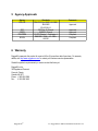
1
RuggedMC™ RMC30
Installation Guide
RuggedCom Inc.
300 Applewood Crescent,
Concord, Ontario
Canada L4K 5C7
Web: http://www.ruggedcom.com/
Tel: +1 905 856 5288
Fax: +1 905 856 1995
Toll Free: 1 888 264 0006
Copyright
COPYRIGHT © 2010 RuggedCom Inc. ALL RIGHTS RESERVED
Dissemination or reproduction of this document, or evaluation and communication of its contents, is not
authorized except where expressly permitted. Violations are liable for damages. All rights reserved,
particularly for the purposes of patent application or trademark registration.
This document contains proprietary information, which is protected by copyright. All rights are reserved. No
part of this document may be photocopied, reproduced or translated to another language without the prior
written consent of RuggedCom Inc.
Disclaimer of liability
We have checked the contents of this manual against the hardware and software described. However,
deviations from the description cannot be completely ruled out.
RuggedCom shall not be liable for any errors or omissions contained herein or for consequential damages
in connection with the furnishing, performance, or use of this material.
The information given in this document is reviewed regularly and any necessary corrections will be
included in subsequent editions. We appreciate any suggested improvements. We reserve the right to
make technical improvements without notice.
Registered Trademarks
Rugged MediaConverter™, ROS™ and RuggedMC™ are trademarks of RuggedCom Inc. Other
designations in this manual might be trademarks whose use by third parties for their own purposes would
infringe the rights of the owner.
Contacting RuggedCom
Corporate Headquarters
RuggedCom Inc.
300 Applewood Crescent
Concord, Ontario
Canada, L4K 5C7
US Headquarters
RuggedCom
1930 Harrison St., Suite 209
Hollywood, Florida
USA, 33020
Tel: +1 954 922 7938 ext. 103
Tel:
+1 905 856 5288
Fax:
+1 954 922 7984
Fax:
+1 905 856 1995
Toll-free: 1 888 264 0006
Toll-free: 1 888 264 0006
Email: [email protected]
Europe Headquarters
RuggedCom
Unit 41, Aztec Centre,
Aztec West, Almondsbury, Bristol
United Kingdom BS32 4TD
Tel:
Fax:
+44 1454 203 404
+44 1454 203 403
Technical Support
Toll Free (North America):
1 866 922 7975
International:
+1 905 856 5288
Email: [email protected]
Web: www.RuggedCom.com
RuggedCom®
2
RuggedMC™ RMC30 Installation Guide Rev 105
Federal Communications Commission Radio Frequency Interference Statement
This equipment has been tested and found to comply with the limits for a Class A digital device pursuant to
Part 15 of the FCC Rules. These limits are designed to provide reasonable protection against harmful
interference when the equipment is operated in a commercial environment. This equipment generates,
uses and can radiate radio frequency energy and, if not installed and used in accordance with the
instruction manual, may cause harmful interference to radio communications. Operation of this equipment
in a residential area is likely to cause harmful interference in which case the user will be required to correct
the interference on his own expense.
Warning: Changes or modifications not expressly approved by RuggedCom Inc. could void the user’s
authority to operate the equipment.
Caution – Use of controls or adjustments or performance of procedures other than those specified herein
may result in hazardous radiation exposure. This product contains no user-serviceable parts. Attempted
service by unauthorized personnel shall render all warranties null and void.
Should this device require service see the “Warranty and Service” section of this installation guide.
Important:
The RuggedMCTM should be installed in a restricted access location where access can only be gained by
service personnel or users who have been instructed about the reasons for the restrictions applied to the
location and about any precautions that shall be taken; and access is through the use of a tool or lock and
key, or other means of security, and is controlled by the authority responsible for the location.
RuggedCom®
3
RuggedMC™ RMC30 Installation Guide Rev 105
Table of Contents
1
2
3
4
5
6
Product Overview.......................................................................................................................................5
1.1 RMC30 Front Panel Description.........................................................................................................6
1.2 RMC30 Side and Bottom View............................................................................................................8
Installation...................................................................................................................................................9
2.1 DIN Rail Mounting...............................................................................................................................9
2.2 Panel Mounting..................................................................................................................................10
2.3 Power Supply Wiring and Grounding................................................................................................11
2.4 Serial Ports – Signal Description.......................................................................................................12
2.4.1 RS232 Data Port........................................................................................................................13
2.4.2 RS422 and RS485 Data Ports...................................................................................................14
2.5 RMC30 Quick Start Recommendations............................................................................................16
Technical Specifications...........................................................................................................................17
3.1 Power Supply Specifications.............................................................................................................17
3.2 Mechanical Specifications.................................................................................................................18
3.3 Operating Environment.....................................................................................................................19
Type Test Specifications..........................................................................................................................20
4.1 IEC 61850-3 Type Tests...................................................................................................................20
4.2 IEEE 1613 Type Tests......................................................................................................................21
4.3 IEC Environmental Type Tests.........................................................................................................22
Agency Approvals.....................................................................................................................................23
Warranty...................................................................................................................................................23
RuggedCom®
4
RuggedMC™ RMC30 Installation Guide Rev 105
1 Product Overview
INTRODUCTION
The RuggedServer™ RMC30 is an industrially
hardened, 2-port serial device server that has
been specifically designed to operate in
electrically harsh and climatically demanding
environments. The RMC30 allows you to
communicate with virtually any serial device via
Ethernet providing simple and reliable network
connectivity.
CONNECTIVITY
•
•
•
•
1-RS232 and 1-RS422/485 port
1-10BaseTX
Fully compliant EIA/TIA RS485 and RS232 ports
Built-In optional RS485 Termination
SERIAL ENCAPSULATION
•
•
•
•
•
Baud rates up to 230 kbps
Point to point and multi-point modes
Convert Modbus RTU to Modbus TCP
Support multiple Modbus masters
Use 'Serial IP' port redirection software to support
PC applications statistics and built-in 'sniffer' for
troubleshooting
The RMC30 is packaged in a compact,
galvanized steel enclosure that allows either
UNIVERSAL POWER SUPPLY OPTIONS
DIN or panel mounting for efficient use of
• Input voltages of 24VDC, 48VDC, and (88cabinet space. It has an integrated power
300VDC or 85-264VAC) for worldwide operability
supply with a wide range of voltages for
• Integrated power supply eliminates need for an
awkward external power transformer
worldwide operability. An operating
• Screw down terminal blocks ensure reliable
temperature range of -40 to +85°C (-40 to
maintenance free connections
+185°F) without the use of internal cooling fans • CSA/UL 60950 safety approved to +85°C
allows it to be placed in almost any location.
DESIGNED FOR HARSH ENVIRONMENTS
• Exceeds IEC 61850-3 requirements for electric
The RMC30 is compliant with EMI and
substations
environmental standards for utility substations, • power
Exceeds IEC 61000-6-2 for industrial
industrial manufacturing, process and control
environments
and intelligent transportation systems
• Exceeds NEMA TS 2 requirements for traffic
control equipment
applications.
•
The RMC30 offers both an RS232 port and a
RS485/422 port simultaneously via a solid
screw down terminal block. The 10Base-T
Ethernet port supports both auto-negotiation
and auto-crossover detection and simplifies
cabling. Simple and intuitive network based
configuration using either the built in Web or
Telnet server makes setup a breeze.
The RMC30's superior ruggedized design
coupled with the Rugged Operating System™
(ROS) provides improved system reliability
making it ideally suited for creating Ethernet
networks for mission critical, real-time, control
applications.
RuggedCom®
Meets IEEE 1613 requirements for electric power
substations
• Fully Independent, 3kV (RMS) Isolated, EIA/TIA
RS485 ports
• Operates over a temperature range of -40°C to
+85°C without the use of fans for improved
reliability
• 18 AWG galvanized steel enclosure and DIN or
panel mounting options provide secure
mechanical reliability
MANAGEMENT AND DIAGNOSTICS
•
•
•
•
Web-based, Telnet, CLI management interfaces
SNMP v2 with traps
Rich set of diagnostics with logging and alarms
Ethernet and Serial LED indicators aid in field
troubleshooting
• Flash memory for easy upgrades
• System watchdog with automatic reset
• Built in real time clock and SNTP time
synchronization
5
RuggedMC™ RMC30 Installation Guide Rev 105
1.1 RMC30 Front Panel Description
Reset Push Button
Power & Alarm
LED Indicators
10Base Tx
Ethernet Port
RS232/422/485
Connector
Transmit(Tx) and
Receive(Rx) LEDs
Power Supply
Connector
Drawing 1 - RMC30 Front Panel Description
The RMC30 LED definitions are as follows:
LED
Activity
Description
Power
Solid (Green)
Alarm
Solid (Red)
Link
Solid (Yellow)
Act
Blinking (Yellow)
Transmitting/receiving Ethernet data.
Tx
Blinking (Yellow)
Transmitting serial data*
Power On
Alarm condition present. For example, Ethernet link failed, selftest error, etc. See RMC30 User's Guide for complete details.
Ethernet link established.
Rx
Blinking (Yellow)
Receiving serial data*
* The Tx/Rx LEDs blink for either RS232 and RS422/485 data.
RuggedCom®
6
RuggedMC™ RMC30 Installation Guide Rev 105
1.2 RMC30 Side and Bottom View
Drawing 2- RMC30 Side and Bottom View
RuggedCom®
7
RuggedMC™ RMC30 Installation Guide Rev 105
2 Installation
2.1 DIN Rail Mounting
Drawing 3 - RMC30 DIN Rail Mounting
RuggedCom®
8
RuggedMC™ RMC30 Installation Guide Rev 105
2.2 Panel Mounting
With the use of an optional panel-mount adapter, the RuggedMCTM series of media converters can be
panel mounted. Drawing 4 shows an example of an RMC unit panel mounted using the optional panel
mount adapter.
The panel mount adapter can be secured to a panel with three screws. The RuggedMCTM product is easily
mounted onto the panel mount adapter via the two metal clips on either side of the unit, and a single screw
located on the bottom.
Drawing 4 - RuggedMCTM panel mounted using optional panel mount mounting adapter.
RuggedCom®
9
RuggedMC™ RMC30 Installation Guide Rev 105
2.3 Power Supply Wiring and Grounding
Drawing 5 - RuggedMCTM Power Supply Inputs
The RuggedMCTM power supply inputs are identical and are connected as follows:
1. +/L = DC (+) / AC (Hot) is connected to the positive (+) terminal if the power source is DC or to the
(Hot) terminal if the power source is AC.
2. -/N = DC (-) / AC (Neutral) is connected to the negative (-) terminal if the power source is DC or to
the (Neutral) terminal if the power source is AC.
3. Surge Ground is connected to the Safety Ground via a braided cable or other appropriate
grounding wire. Surge Ground is used as the ground conductor for all surge and transient
suppression circuitry internal to the RuggedMCTM.
4. Safety Ground should be connected to the power supply ground. This should be the safety
ground for AC inputs or the equipment ground bus for DC inputs.
Note: Surge Ground must be disconnected from Chassis Ground during HIPOT
(Dielectric strength) testing.
Notes:
1. For 125/250VDC rated equipment: An appropriately rated 300VDC circuit breaker must be
installed within 3 meters of unit.
2. For 110/230VAC rated equipment: An appropriately rated 250VAC circuit breaker must be
installed within 3 meters of the unit
3. A circuit breaker is not required for 48 or 24VDC rated equipment.
4. For multiple supplies, separate circuit breakers must be installed. Equipment must be
installed according to the applicable country wiring codes.
RuggedCom®
10 RuggedMC™ RMC30 Installation Guide Rev 105
2.4 Serial Ports – Signal Description
The RMC30 is equipped with a seven-terminal phoenix style connector. This connector can accommodate
one RS232 connection, and one RS485/422 connection. Drawing 6 shows the connections for RS232,
RS485, and RS422 communications. The following sections describe installation details for respective
ports.
RS232: Rx(In) & Tx(out)
Shared Common
RS485: Rx/Tx +/-
RS422: Rx +/- & Tx+/-
Drawing 6- Serial RS232, RS485, and RS422 terminal block connections
RuggedCom®
11
RuggedMC™ RMC30 Installation Guide Rev 105
2.4.1 RS232 Data Port
The RMC30 is equipped with a single EIA/TIA RS232 compliant port, consisting of three terminals:
Transmit, Receive, and Common. The RS232 port is intended for point-to-point applications only. The
EIA/TIA guidelines for RS232 communications include (but are not limited to) the following:
1. To minimize the effects of ambient electrical noise, shielded cabling is recommended.
2. Reliable communications within 15m. Greater distances are possible.
3. Communications of up to 120kbaud signal rate.
The RMC30's RS232 port does not use an industry standard DB9 connector but rather a 'Phoenix' style
compression connector. See Table 1 and Drawing 3 for pinouts.
The RS232 data port has two modes of operations; only one mode is active at any given time:
1. Communications with IEDs (intelligent electronic devices such as PLC, RTU, etc.)
2. Console configuration of the RMC30.
Two activate console configuration mode the user must press the <CTRL>Z key for approximately 10
seconds during power up. To deactivate console mode requires restting the RMC30.
Table 1 - RS232 DB9 Pinouts
RMC30 Connector
DB9 Connector Pin:Signal
RS232:Tx
2:RD (Receive Data)
RS232:Rx
3:TD( Transmit Data)
COM
5:SGND (Singnal Ground)
RMC30 Phoenix
Connector
DB9 Female
Connector
Rx
1
Tx
2
COM
3
-Rx
4
RS485
+Rx
5
RS422
-Tx
RS232
6
7
8
9
+Tx
Drawing 7 - RS232 DB9 Cable Wiring
RuggedCom®
12 RuggedMC™ RMC30 Installation Guide Rev 105
2.4.2 RS422 and RS485 Data Ports
The RMC30 is equipped with a single RS485 / RS422 data port. In half duplex mode (See section 2.5 for
RMC30 configuration) the RS485 connections (Rx +, Rx -, COM) should be connected. In full-duplex
mode the RS422 connections (Rx+, Rx -, Tx+, Tx-, COM) should be connected. Both RS485 and RS422
can accommodate multi-drop networks, for master-slave serial network communications. For both RS485 /
RS422 connections, the following general guidelines should be followed:
1. To minimize the effects of ambient electrical noise, shielded cabling is recommended
2. The correct polarity must be observed throughout the daisy chain
3. The number of devices wired should not exceed 32, and total distance should be less than 4000
feet (at 100Kbps)
4. The COM terminal should be connected to the common wire inside the shield.
5. The shield/COM should be grounded at ONE single point to avoid loop currents
6. The twisted pair should be terminated at each end of the chain. (Typically with a 120Ohm resistor
and a 10nF capacitor in series across the twisted pair)*
* Both data terminal pairs (Rx +/- and Tx +/-) are terminated by default from the factory. To remove
termination: Open the cover and remove jumper JP1 and/or JP2 (JP1 for Rx+, Rx- terminals, JP2 for Tx+,
Tx- terminals) depending on which port termination is NOT required. Termination provided is a 120 Ohm
resistor in series with a 10nF capacitor as per the ModBus 1.0 specification. In general termination should
be left in place unless it is detrimental to communications.
Note: Transient protection is provided on all RMC30 terminals. Lightning strikes and ground surge
currents can cause large momentary voltage differences between ends of communication links. To ensure
maximum reliability of the entire link, all equipment should have similar transient protection installed.
RuggedCom®
13
RuggedMC™ RMC30 Installation Guide Rev 105
Drawing 8 - Conceptual RS485 wiring diagram
RuggedCom®
14 RuggedMC™ RMC30 Installation Guide Rev 105
2.5 RMC30 Quick Start Recommendations
The following is an excerpt from the RMC30 User's Guide. It is included to aid those users experienced
with communications equipment that may wish to attempt to configure the server without fully reading the
guide. We recommend review of the User Guide for a complete understanding of the RMC30 serial device
server.
1. Attach a PC running terminal emulation software to the RS232 port and apply power to the chassis
(default baud rate, data bits, parity - “57600 8 n”, no hardware/software flow control). Set the terminal
type to VT100. See section 2.4.1 for making an appropriate RS232 cable.
2. While the RMC30 is powering on press and hold the <CTRL>Z key. The following prompt should
appear on the screen:
Console mode...
Type 'yes' if you want to enter MAIN console mode:
After entering 'yes' and then pressing any key the main login screen will appear. Using the default
password of “admin” will provide access to the User Interface (see Chapter 1).
3. As an alternative to steps 1 and 2, you may use Telnet or HTTP via the default IP address of
192.168.0.1 to configure the RMC30. This may require some minor setup of you PC network interfaces
to ensure that the RMC30 can be reached.
4. Configure the server’s IP address (Administration, Configure IP Services, IP Address) and Subnet
Mask (Administration, Configure IP Services, Subnet). If instead you wish the server to load the
address via DHCP, set the address type to dynamic (Administration, Configure IP Services, IP
Address Type). See Chapter 1 for more details.
5. You may wish to change the default guest, operator and administration passwords (Administration,
Configure IP Services, Configure Passwords). See Chapter 1 for more details.
6. The serial ports may be configured to support Serial encapsulation or TcpModbus, placing connections
to or accepting connections from a remote host. See Chapter 2 for more details
7. You may wish to configure the security aspects of the server. By default the server allows a number of
incoming telnet sessions. TFTP sessions are allowed, and may read (and not write) the servers
configuration. The server also allows a number of web management sessions to occur. You can limit
the numbers of these sessions or disable them completely (Administration, IP Services). If remote
SNMP management or traps are desired, configure the appropriate manage station (Administration,
Configure SNMP Management Stations).
8. Further concerns such as fine-tuning serial port parameters, measuring and optimizing performance are
dealt with by reading the guide fully.
RuggedCom®
15
RuggedMC™ RMC30 Installation Guide Rev 105
3 Technical Specifications
3.1 Power Supply Specifications
Power Supply Type
Minimum
Input
Maximum
Input
24 VDC
48 VDC
HI (88/300 VDC) 1
HI (120/240 VAC) 1
18 VDC
36 VDC
88 VDC
85 VAC
36 VDC
72 VDC
300 VDC
264 VAC
Internal
Fuse
Rating
3.15A(T) 2
3.15A(T) 2
3.15A(T) 2
Maximum Power
Consumption
3W
Notes: 1 – This is the same power supply for both AC and DC.
2 – (T) Denotes time-delay fuse
RuggedCom®
16 RuggedMC™ RMC30 Installation Guide Rev 105
3.2 Mechanical Specifications
Drawing 9 - RMC30 Mechanical Dimensions
Parameter
Dimensions
Weight
Enclosure
RuggedCom®
Value
4.30 x 2.40 x 3.30 inches
Comments
(Length x Width x Height)
(110) x (61) x (84) mm
1.5 lb (0,68 Kg)
18 gauge Galvanized Steel
17
RuggedMC™ RMC30 Installation Guide Rev 105
3.3 Operating Environment
Parameter
Range
Ambient Operating
Temperature
-40 to 85°C
Ambient Relative Humidity
Ambient Storage
Temperature
RuggedCom®
5% to 95%
Comments
Ambient Temperature as measured from a
30cm radius surrounding the center of the
RuggedMCTM enclosure.
Non-condensing
-40 to 85°C
18 RuggedMC™ RMC30 Installation Guide Rev 105
4 Type Test Specifications
4.1 IEC 61850-3 Type Tests
IEC 61850-3 EMI TYPE TESTS
Test
Description
IEC 61000-4-2
ESD
Test Levels
Severity
Levels
Enclosure Contact
+/- 8kV
4
Enclosure Air
+/- 15kV
4
IEC 61000-4-3
Radiated RFI
Enclosure ports
20 V/m
x
IEC 61000-4-4
Burst (Fast Transient)
Signal ports
+/- 4kV @ 2.5kHz
x
D.C. Power ports
+/- 4kV
4
A.C. Power ports
+/- 4kV
4
Earth ground ports1
+/- 4kV
4
Signal ports
+/- 4kV line-to-earth, +/2kV line-to-line
4
D.C. Power ports
+/- 2kV line-to-earth, +/1kV line-to-line
3
A.C. Power ports
+/- 4kV line-to-earth, +/2kV line-to-line
4
Signal ports
10V
3
D.C Power ports
10V
3
10V
3
Earth ground ports
10V
3
N/A
IEC 61000-4-5
IEC 61000-4-6
Surge
Induced (Conducted) RFI
A.C. Power ports
1
IEC 61000-4-8
Magnetic Field
Enclosure ports
40 A/m continuous, 1000
A/m for 1 s
IEC 61000-4-29
Voltage Dips & Interrupts
D.C. Power ports
30% for 0.1s, 60% for 0.1s, N/A
100% for 0.05s
A.C. Power ports
30% for 1 period, 60% for
50 periods
N/A
100% for 5 periods, 100%
for 50 periods 2
N/A
Signal ports
2.5kV common, 1kV diff.
mode@1MHz
3
D.C. Power ports
2.5kV common, 1kV diff.
mode@1MHz
3
A.C. Power ports
2.5kV common, 1kV diff.
mode@1MHz
3
Signal ports
30V Continuous, 300V for
1s
4
IEC 61000-4-11
IEC 61000-4-12
IEC 61000-4-16
RuggedCom®
Damped Oscillatory
Mains Frequency Voltage
19
RuggedMC™ RMC30 Installation Guide Rev 105
D.C. Power ports
30V Continuous, 300V for
1s
4
IEC 61000-4-17
Ripple on D.C. Power
Supply
D.C. Power ports
10%
3
IEC 60255-5
Dielectric Strength
Signal ports
2kVac (Fail-Safe Relay
output)
N/A
D.C. Power ports
1.5kVdc
N/A
A.C. Power ports
2kVac
N/A
Signal ports
5kV (Fail-Safe Relay
output)
N/A
D.C. Power ports
5kV
N/A
A.C. Power ports
5kV
N/A
Test Levels
Severity
Levels
Enclosure Contact
+/- 8kV
N/A
Enclosure Air
+/- 15kV
N/A
IEC 60255-5
H.V. Impulse
4.2 IEEE 1613 Type Tests
IEEE 1613 (C37.90.x) EMI IMMUNITYTYPE TESTS
Test
Description
IEEE C37.90.3
ESD
IEEE C37.90.2
Radiated RFI
Enclosure ports
35 V/m
N/A
IEEE C37.90.1
Fast Transient
Signal ports
+/- 4kV @ 2.5kHz
N/A
D.C. Power ports
+/- 4kV
N/A
+/- 4kV
N/A
Earth ground ports
+/- 4kV
N/A
Signal ports
2.5kV common mode
@1MHz
N/A
D.C. Power ports
2.5kV common, 1kV diff.
mode@1MHz
N/A
A.C. Power ports
2.5kV common, 1kV diff.
mode@1MHz
N/A
Signal ports
5kV (Fail-Safe Relay
output)
N/A
D.C. Power ports
5kV
N/A
A.C. Power ports
5kV
N/A
Signal ports
2kVac
N/A
D.C. Power ports
1.5kVdc
N/A
A.C. Power ports
2kVac
N/A
A.C. Power ports
3
IEEE C37.90.1
IEEE C37.90
IEEE C37.90
RuggedCom®
Oscillatory
H.V. Impulse
Dielectric Strength
20 RuggedMC™ RMC30 Installation Guide Rev 105
4.3 IEC Environmental Type Tests
ENVIRONMENTAL TYPE TESTS
Test
Description
Test Levels
Severity
Levels
IEC 60068-2-1
Cold Temperature
Test Ad
-40°C, 16 Hours
N/A
IEC 60068-2-2
Dry Heat
Test Bd
+85°C, 16 Hours
N/A
IEC 60068-2-30
Humidity (Damp Heat,
Cyclic)
Test Db
95% (non-condensing),
55°C , 6
cycles
N/A
IEC 60255-21-1
Vibration
Tests Fc
2g @ (10 - 150) Hz
Class 22
IEC 60255-21-2
Shock
Tests Ea
30g @ 11mS
Class 22
Notes: 1 – Only applicable to functional earth connections separated from the safety earth connection.
2 – Class 2 refers to "Measuring relays and protection equipment for which a very high security margin is required or
where the vibration levels are very high ( e.g. shipboard application and for severe transportation conditions").
RuggedCom®
21
RuggedMC™ RMC30 Installation Guide Rev 105
5 Agency Approvals
Agency
CSA, CE
FCC
CISPR
FDA/CDRH
IEC/EN
Standards
CSA C22.2 No. 60950, UL 60950,
EN 60950
EN 61000-6-2
FCC Part 15, Class A
EN55022, Class A
21 CFR Chapter 1, Subchapter J
EN60825-1:1994 + A11:1996 +
A2:2001
Comments
Approved
Approved
Approved
Compliant
Compliant
6 Warranty
RuggedCom warrants this product for a period of five (5) years from date of purchase. For warranty
details, visit http://www.ruggedcom.com/ or contact your customer service representative.
Should this product require warranty or service contact the factory at:
RuggedCom Inc.
300 Applewood Crescent,
Concord, Ontario
Canada L4K 5C7
Phone: +1 905 856 5288
Fax: +1 905 856 1995
RuggedCom®
22 RuggedMC™ RMC30 Installation Guide Rev 105