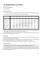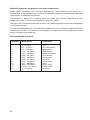
1
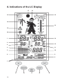
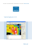
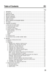
Operating Instructions
Weather station
„WS 200“
ELV Elektronik AG · PF 1000 · D-26787 Leer
Telefon 0491/6008-88 · Telefax 0491/6008-244
These operating instructions belong with this product. They contain important information
for putting it into service and operating it. This should be noted also when this product is
passed on to a third party.
Therefore look after these operating instructions for future reference!
A list of contents with the corresponding page numbers can be found in the index on page 44.
2
Introduction
Dear Customer,
Thank you for purchasing this product.
The product has been EMV-tested and thus meets the requirements of the valid European
and national guidelines. CE-conformity has been proven and the corresponding declarations
deposited with the manufacturer.
In order to maintain this condition and ensure safe operation, you, as the user, have to observe
this operating manual.
Prior to using the product for the first time, please read the entire operating manual and observe
all operating and safety instructions.
We should already like to point out now the correct order for commissioning the
products. Please also observe the installation and calibration instructions in this
operating manual as well as the information about impairment of radio transmission
between the sensors and base station.
All company names and product descriptions listed herein are the trademarks of the
respective manufacturers. All rights are reserved.
3
Table of Contents
Page
1. Intended Use ................................................................................................................... 6
2. Scope of Delivery ............................................................................................................ 6
3. Explanation of Symbols ................................................................................................. 7
4. Features and Functions ................................................................................................. 7
a) Base Station ................................................................................................................ 7
b) Multipurpose Sensor .................................................................................................. 9
c) Outdoor Sensor .......................................................................................................... 9
5. Safety Instructions ......................................................................................................... 9
6. Battery and Accumulator Information ....................................................................... 10
7. Preparation and Start-up ............................................................................................. 11
a)
b)
c)
d)
Start-up of the Multipurpose Sensor ....................................................................... 11
Start-up of Other Sensors ........................................................................................ 14
Start-up of the Base Station ..................................................................................... 14
Log-In of Sensors during Operation ......................................................................... 15
8. Indications of the LC Display ...................................................................................... 16
9. Configuration and Operation ...................................................................................... 18
a) Basic Settings, Configuration ................................................................................... 18
Calling-up the configuration mode ........................................................................... 19
Setting the date and time ......................................................................................... 19
Entering degrees of latitude and longitude .............................................................. 20
Setting the time zone ................................................................................................ 21
Assigning the march indication ................................................................................ 21
Selecting the unit for the temperature indication .................................................... 22
Selecting the unit for the wind speed ...................................................................... 22
Exiting the configuration mode ................................................................................ 22
b) Operation .................................................................................................................. 23
Selecting the indoor temperature ............................................................................. 23
Selecting the outdoor temperature .......................................................................... 23
Selecting the outdoor sensor ................................................................................... 23
Indicating the MIN/MAX values ................................................................................ 23
Indicating the time/date for the single extreme value ............................................. 24
Deleting the MIN/MAX values ................................................................................... 25
Setting the contrast of the LC display ..................................................................... 25
4
Page
c) Further Functions ...................................................................................................... 26
Indication of the moon phases ................................................................................. 26
Weather Willi ............................................................................................................. 26
Weather forecast ....................................................................................................... 26
Wind symbol indication (wind cone) ........................................................................ 27
Comfort indicator ...................................................................................................... 27
Frost warning ............................................................................................................ 27
Storm warning ........................................................................................................... 27
10. Replacing the Battery .................................................................................................. 28
a) Base Station .............................................................................................................. 28
b) Multipurpose Sensor, Outdoor Sensors .................................................................. 28
11. Troubleshooting ............................................................................................................ 29
12. Coverage ........................................................................................................................ 31
13. Maintenance and Cleaning .......................................................................................... 32
a) General ...................................................................................................................... 32
b) Cleaning the Base Station ........................................................................................ 32
c) Cleaning the Multipurpose Sensor and the Outdoor Sensors ................................ 33
14. Handling ......................................................................................................................... 34
a) General ...................................................................................................................... 34
b) Base Station .............................................................................................................. 34
c) Multipurpose Sensor ................................................................................................ 34
15. Explanation of Terms ................................................................................................... 35
16. Disposal ......................................................................................................................... 37
a) General ...................................................................................................................... 37
b) Disposal Instructions for Batteries/Accumulators ................................................... 37
17. Technical Data .............................................................................................................. 38
18. Position Table (Latitude and Longitude Degrees) .................................................... 39
19. Brief Instructions .......................................................................................................... 40
5
1. Intended Use
The Weather Station WS 200 is a high-quality universal weather measuring system which is able
to process a large number of weather data and additional information and can indicate both
current values and forecasts.
All relevant data are simultaneously presented on the LC display, further data can be indicated
by pressing a key.
A special feature is the figure of the ”Weather Willi”. The clothes he wears show the current
outdoor temperature range, his hair and scarf reflect the range of the current wind speed and
his umbrella indicates prognosticated rain.
The forecasts of the basis station are to be considered orientation values. They do not represent
an absolutely accurate prognosis. The manufacturer does not take over any responsibility for
incorrect indications, measured values or weather forecasts and the consequences thereof.
This product is designed for private use and is not suitable for medical purposes or for informing
the public.
The components of this product are not a toy, they contain fragile glass and ceramic parts.
Set up all the components in such a manner that they are out of the reach of children.
The product is operated by batteries. All external sensors transmit their data to the base station
via radio in the range of 868 MHz (coverage up to 100m in the free field).
Use other than that described above will lead to damage to the product.
Please read the complete operating instructions before use. They contain important
information for correct installation, functioning and operation.
2. Scope of Delivery
• Weather Station WS 200
• Plastic foot for the weather station
• Multipurpose sensor KS 200
• Mounting rod for the multipurpose sensor
• Specially shaped aluminium part for installing the mounting rod
• Hose band clip
• Operating instructions
6
3. Explanation of Symbols
The symbol with the lightening in the triangle is used when your health is at risk, e.g.
through an electric shock
An exclamation mark in a triangle indicates important information in these operating
instructions which must be observed without fail.
The ”hand” symbol can be found when you are to be given tips and information on
operation.
4. Features and Functions
a) Base Station
Indication of indoor temperature and air humidity
• temperature indication in °C or °F / air-humidity indication in % rH (% relative air humidity))
• can be switched to the indication of the inside dew point
• storage of minimum/maximum temperatures with the corresponding times/dates of
measurement
• storage of minimum/maximum air humidity with the corresponding times/dates of measurement
• Climatic comfort zone indicator
• graphical representation of the march of temperature over the last 24 hours
Indication of an outdoor sensor (temperature and air humidity)
• indication of the data of the multipurpose sensor or of the 8 outdoor sensors for temperature/
air humidity
• optional indication of temperature, dew point or perceived temperature (windchill)
• storage of minimum and maximum temperatures with the corresponding times/dates of
measurement
• storage of minimum and maximum air humidity with the corresponding times/dates of
measurement
• Graphical representation of the march of temperature over the last 24 hours
Indication of wind speed
• wind speed indication with selectable units: km/h, m/s, mph
• storage of the maximum wind speed values with the corresponding times/dates of measurement
• additional graphical representation (wind cone) for light, moderate and strong winds
7
Indication of the march of air pressure/indication of the tendency of
air pressure
• graphical representation of the pressure march over the last 24 hours
• storage of the minimum and maximum air pressure values with the corresponding times/
dates of measurement
• indication of the tendency of air pressure in 5 different steps: strongly increasing, increasing,
unchanging, decreasing, strongly decreasing
Symbol indication of the weather forecast
• symbols for: rainy, cloudy, bright, sunny
Indication of time and date
• integrated quartz clock
Indication of sunrise and sunset
• based on the locations which are to be entered individually, a calculation is possible in the
range from -60°N to +60°N
Indication of the phases of the moon
• indication of the current phase of the moon in 8 steps: new moon, waxing moon, full moon,
waning moon (with intermediate steps)
Warning functions
• frost warning for a temperature decreasing below 4°C (symbol: ice crystal)
• storm warning for a sharp air pressure decrease within a short period of time (symbol: danger
sign)
”Weather Willi” weather indicator
Following the almost forgotten weather house, in which a person with an umbrella steps out of
the door in case of bad weather and a person lightly dressed appears in case of good weather,
the WS 200 is provided with the ”Weather Willi”.
The behaviour of this figure depends on various weather factors so that you can see at a glance
which dressing you should put on if you want to go outside.
This indicator does not only reflect the current measured values for outdoor temperature, air
humidity and wind, but also the weather forecast data.
Therefore, many different presentations and kinds of clothing of ”Weather Willi” are
provided and shown according to the weather situation.
• The clothing of ”Weather Willi” depends on the outdoor temperature measured at the
multipurpose sensor and ranges from swimming shorts up to the complete winter dressing
including a cap, a muffler and gloves.
• At wind speeds higher than 20 km/h (moderate wind) the hair of ”Weather Willi” blow in the
wind and if he has put a muffler on – dependent on the temperature, too – it also blows in the
wind.
• If the weather forecast predicts rain, the ”Weather Willi” will take his umbrella with him.
8
b) Multipurpose Sensor
• Radio transmission of:
- wind speed
- temperature
- air humidity
C) Outdoor Sensor
• Radio transmission of:
- temperature
- air humidity
5. Safety Instructions
The warranty will lapse for damage due to non-compliance with these operating
instructions. We shall not be held liable for any consequential damage or loss!
We shall not accept liability for damage to property or personal injury caused
by incorrect handling or non-compliance with the safety instructions. Any claim
to warranty will lapse in such cases.
Dear Customer, the following safety and risk instructions are intended not only for the
protection of your health but also for the protection of the device. Please read through the
following points attentively:
Do not use this product in hospitals or medical institutions. The outdoor sensor does only emit
relatively weak radio signals. These radio signals could, however, lead to malfunctions in lifesupporting systems. The same may possibly apply to other areas.
The weather station is only designed for dry rooms. Do not expose it to direct sunlight, high
temperatures, coldness or excessive dampness and humidity.
The multipurpose sensor (and separately/additionally available outdoor sensors) is suitable for
operation in non-protected outdoor areas.
For safety and licensing (CE) reasons, unauthorised conversion of and/or modifications to the
product are not permitted.
Do not leave packaging material lying around carelessly. Plastic foil/bags and polystyrene parts
etc. could become dangerous toys for children.
Handle the product with care. It can be damaged through impact, blows or by being dropped
even from a low height.
9
6. Battery and Accumulator Information
• Batteries/accumulators must be kept out of the reach of children.
• Make sure that the batteries/accumulators are inserted with the correct polarity.
• Do not leave the batteries/accumulators lying around in the open; there is a risk of their being
swallowed by children or domestic animals. If swallowed, immediately contact a doctor.
• Leaking or damaged batteries/accumulators can cause burning if they come into contact with
the skin. For this reason you should use suitable protective gloves.
• Make sure that batteries/accumulators are not short-circuited or thrown into a fire. There is
a risk of explosion!
• Never dismantle batteries/accumulators!
• Batteries may not be recharged. There is a risk of explosion!
• In case of longer periods of non-use (e.g. during storage) remove the inserted batteries/
accumulators to avoid damage by a leaking battery/accumulator.
• Always replace the whole set of batteries/accumulators. Do not mix batteries/accumulators
of different types/manufacturers.
• Never mix batteries with accumulators!
Please note:
The weather station, multipurpose sensor and possibly used outdoor sensors can be
operated by accumulators. However, due to the lower voltage of accumulators
(accumulator = 1.2 V, battery = 1.5 V) the operating life can be decreased. Moreover,
the radio coverage will be reduced, in rare cases even malfunctions can be caused.
Therefore, the following rule applies:
If you face any problem during the operation based on accumulators, use batteries
instead of them. We recommend you to operate the weather station, multipurpose
sensor and possibly existing outdoor sensors only with high-quality alkaline batteries.
Please refer to chapter 16 for the environmental-friendly disposal of batteries
and accumulators.
10
7. Preparation and Start-up
Please note:
First start up all provided sensors (multipurpose sensor and possibly existing
outdoor sensors) (insert batteries) before starting up the weather station itself.
If you fail to follow this order of proceeding, it may be that the base station is
not able to identify the provided sensors!
It is principally recommended to test the base station with all its sensors (supplied multipurpose
sensor and possibly existing outdoor sensors) first in a room, before installing the sensors
outside.
The distance between the base station and the sensors must be at least 2m to avoid
interference. Do not place the sensors side by side, but install them throughout the
area (e.g. if you have purchased several additional sensors).
If you find out that one of the sensors is not received after the installation, you can take it for
granted that the radio reception is too weak.
You avoid complex and time-consuming troubleshooting, if you perform this first functional test.
a) Start-up of the Multipurpose Sensor
• Open the housing of the multipurpose sensor. First, turn
the lower cover of the housing a little bit towards the arrow
as shown on the right (1) and then pull it carefully
downwards (2).
• There are two options to mount the sensor on a mast:
1. Own installation mast, e.g. purchased in the DIY
superstore
2. Optionally available installation mast matched to the
system (not included in the scope of delivery, is to be
ordered separately)
Fig. 1
11
Proceed as follows for mounting:
1. Own individual installation mast
• Screw out the two small screws at the bottom
of the multipurpose sensor a little bit.
• Insert the supplied mounting rod of 25cm
from into the multipurpose sensor the bottom
in such a way that the two holes in the mounting
rod are directly positioned under the screws.
supplied
mounting rod
supplied shaped
aluminium part
• Then tighten the two screws carefully (screws
are to be screwed into the holes of the
mounting rod).
mounting clip
• The mast required must have a diameter of
between 25mm and 45mm. It can either be a
free mast or a mounting angle, e.g. for a
satellite dish.
installation mast
• Position the shaped aluminium part on one
side of this mast/mounting angle and put a
hose band clip over the two parts.
Fig. 2a
• Set the short mounting rod of the sensor against the other side of the shaped aluminium part
(on the right side in Figure 2 above) and tighten the hose band clip by using a screwdriver.
2. Optionally available installation mast (not included in the scope of delivery)
If you want to drive the rod with the flat tip (serves as an earth tip) into the ground by
means of a hammer, use a suited wooden clump in any case to protect the mast.
Otherwise, the upper end of the rod will be damaged (installation of the sensor mast
will not be possible any longer), guarantee will lapse!
• Assemble the single parts of the sensor mast. Plastic couplers combine the individual rods.
plastic coupler
Fig. 2b
• The flat rod end serves as an earth tip.
12
• After the installation of the mast, insert three batteries (AA/
Mignon) with the correct polarity into the battery compartment. You will find the corresponding image in the battery
compartment (see also figure 3 on the right).
If possible use alkaline batteries.
As already described in chapter 6, accumulators
can be used, too. They, however, can have a
negative influence on the operating life, coverage
and operational safety.
• During the following 5 minutes, the sensor is in the so
called synchronisation mode in which it sends one data
package every 4 seconds.
During this period of time you should insert the batteries
into the base station so that it can identify the sensor.
Fig. 3
• Then close the housing of the multipurpose sensor again, slide the cover upwards and lock
it by turning it to the right (reverse direction than shown in Fig. 1).
• To avoid unnecessary long ways for checking the functions, the final positioning, e.g. in the
garden, should be performed only after a successfully completed functional test as described
at the beginning of this chapter.
The correct location of the multipurpose sensor is decisive for obtaining the most accurate
measuring values.
The temperature sensor inside the housing of the multipurpose sensor is positioned
at the top below the ”umbrellas” in a ventilated area of the housing. Therefore, in
direct sunlight only a slightly higher temperature value will be measured.
Please ensure that the wind sensor at the tip of the multipurpose sensor is not
positioned too close to houses, trees etc., because this could falsify the measured
values of the wind speed.
That’s why, the multipurpose sensor should be set up in a free space, e.g. in the
garden.
• The mast must firmly stick in the soil with the multipurpose sensor being positioned
approximately 2 m above the ground.
When selecting the place of installation, consider the safety for children, pets,
vehicles etc.
If the multipurpose sensor falls down, there is risk of injury or damage to
vehicles or other objects.
Make sure that there are no pipes (e.g. hose pipes for irrigating systems or
similar) at the place where the earth rod is inserted/driven into the ground.
13
b) Start-up of Other Sensors
If you want to use several additional temperature/air humidity sensors suited to the Weather
Station WS 200, insert the batteries into the sensor(s) now. A maximum number of 8 of such
sensors can be operated.
The installation, addressing and start-up of the sensor is to be performed according to their
operating instructions.
c) Start-up of the Base Station
The base station is designed to indicate all registered and calculated data on a clearly arranged
LC display. The sensors for indoor use (temperature, air humidity, air pressure) are also included
in the housing of the base station.
For this reason, ensure during the start-up or installation of the base station that a heating or
ventilation system (e.g. an air-conditioning system) is not in its proximity, because false data
could be indicated in such a case. Avoid direct sunlight, too!
Keep to the following order of steps during the start-up:
• Open the battery compartment on the back side of the base station (remove the foot first, if
necessary!).
• Insert four batteries (AA/Mignon) in the battery compartment paying attention to the correct polarity. You
will find the corresponding image in the battery
compartment (see also figure 4 on the right).
If possible use alkaline batteries.
As already described in chapter 6, accumulators can be used, too. They, however, can
have a negative influence on the operating
life, coverage and operational safety.
• Close the battery compartment again.
• If the batteries are inserted, all segments of the LC
display will be shown briefly.
Fig. 4
• Afterwards, the base station activates the synchronisation mode for 15 minutes. In this period
of time all sensors received will be indicated one after the other.
14
If all your installed sensors have already been received, you can cause a premature
exit of the synchronisation mode by pressing any button, provided that all sensors
have already completed their own synchronisation mode.
If you face any problem in the identification of one sensor, you should wait as long
as the synchronisation time is finished. This process takes 15 minutes.
• After the synchronisation, the normal display of all weather data is shown.
Only sunrise and sunset as well as the phase of the moon have not been indicated
yet, because time and data are to be set before.
• Configure the base station as described in chapter 9 ”Configuration and Operation”.
• The base station can either be hung up on the wall (a suited opening is provided on the back
side) or placed on a foot onto a surface.
If you drive a nail into the wall or drill a hole for a plug with screw for this
purpose, pay attention that no power, gas or water pipes can be damaged,
grave danger!
• If you want to use the foot, first put the front central spike of the foot into the supports on the
back side of the base station. Then, swing the foot a little bit back till the two rear spikes lock
into the catch supports at the bottom of the base station.
d) Registration of Sensors during Normal Operation
When starting up the product, all available suited sensors are registered at the base station in
the synchronisation mode and then received during normal operation
(time required for the synchronisation of the base station takes about 15 minutes after inserting
the batteries, time required for the synchronisation of the sensors takes about 5 minutes after
inserting the batteries).
To register further new, additionally purchased sensors (or sensors lost during the battery
replacement) you do not need to follow the procedure of the initial start-up.
All data saved (minimum and maximum values, time etc.) would be lost during this
kind of proceeding.
But if the new sensor is not indicated, the problem may be found in the coverage (see
chapter 12 ”Coverage”).
Every day, the base station performs a synchronisation test at 8 a.m. and 6 p.m. so that it can
identify new sensors (or a sensor with battery replacement) automatically.
15
8. Indications of the LC Display
17
16
15
15
18
14
19
20
1
13
2
12
3
4
11
5
10
6
9
8
7
A
16
B
C
D
E
1
indoor temperature
2
indoor air humidity
3
comfort zone indicator (for indicating comfortable/uncomfortable climate)
4
indication of the air pressure tendency
5
graphical presentation of the march (history), according to the unit selected
6
indication of empty battery (”LoBat”)
7
time and date indication
8
sunset time
9
sunrise time
10
current wind speed
11
current air-humidity value of the selected outdoor sensor
12
sensor number (no indication, if the multipurpose sensor has been selected)
13
current temperature value of the selected outdoor sensor
14
analogue temperature indication of the multipurpose sensor
15
symbols for the weather forecast (sunny, bright, cloudy, rainy)
16
animated ”Weather Willi” symbol
17
symbol for the phase of the moon
18
additional graphical representation (wind cone) for light, moderate and strong winds
19
bad weather warning
20
frost warning
Control key functions in normal operation (see chapter ”Configuration” for further functions):
A IN
point
Switching the indoor temperature indication between temperature/dew
B
SENSOR
Selection of the outdoor sensor
C
MIN/MAX
Selection of the minimum or maximum value indication
D
RESET
No function
E
OUT
Switching the outdoor temperature indication between
temperature/dew point/windchill
Other symbols/terms:
Indicates that this value is presented in the march indication (5)
DEWPOINT
Dew point
WIND CHILL
Perceived temperature
MIN/MAX
Minimum or maximum indication is active
17
9. Configuration and Operation
When the batteries have been inserted into the sensors and the batteries have been inserted
subsequently into the base station (this order is to be strictly followed), the data transmitted via
radio by the sensors should appear in the LC display of the base station.
a) Basic Settings, Configuration
The following settings are still required for operation:
• year, month, day, hour, minute
• latitude and longitude degrees of your location
• time zone
Only after these settings, the phase of the moon, MIN-/MAX-data and the sunrise/
sunset times as well as the date and time will be indicated.
Additional setting options:
• assignment of the march indication (air pressure, indoor or outdoor temperature; standard:
air pressure)
• unit of the temperature measurement (standard: °C)
• unit of the wind speed measurement (standard: km/h)
In the configuration mode the keys have the following functions:
Imprint
Function
Description
IN
SENSOR
MIN/MAX
RESET
OUT
EXIT
+
NEXT
(not used, no function)
Decrease value
Exit the configuration mode
Increase value
Go to next setting
This key layout is also given on the back side of the weather station.
18
Please note:
If you press the + or - key during the individual settings a little bit longer, the values
will be changed rapidly.
After each setting procedure you can exit the configuration mode by pressing the
EXIT key or you can go the the next setting by activating the NEXT key.
The configuration is performed according to the following order:
year month day minutes hours latitude degree (LA = latitude) Längengrad (LO = “Longitude”) Zeitzone (ti) assignment of the march indication temperature unit wind unit
Afterwards, the setting order restarts from the beginning.
Calling-up the configuration mode
IN
>2 seconds
Press the IN key for approx. 2 seconds till the display
changes.
The configuration mode can be closed at any time by
pressing the EXIT key (= MIN/MAX). See ”Exiting the
Configuration Mode”.
Setting the date and time
+
-
year
NEXT
+
Press the NEXT key.
-
month
-
day
-
minutes
-
hours
NEXT
+
NEXT
Set the day via the + and - keys.
Press the NEXT key.
NEXT
+
Set the month via the + and - keys.
Press the NEXT key.
NEXT
+
Set the current year via the + and - keys.
Set the minutes via the + and - keys.
Press the NEXT key.
Set the hours via the + and - keys.
Press the NEXT key, afterwards you can set the latitude
degree (in the display appears LA = latitude). See next page.
19
Entering the degrees of latitude/longitude
The entry of the location of the weather station is required
for the calculation of sunrise and sunset times.
The degree of latitude can be entered in the range from 60.0° to +60.0°.
The degree of longitude can be entered in the range from
0.0° to 360.0°.
The position of Berlin is programmed by the manufacturer.
You can determine your location in different ways:
• You find a table with the coordinates of the most important
German towns in the chapter ”Position Table”. Select a
town close to you and enter its coordinates.
• If you possess a GPS navigation device, e.g. in your car
or a mobile one, you can take over its location information
and then you have your exact position.
• You can also get the exact coordinates via the Internet.
It provides numerous pages which contain information
on navigation.
Please consider the fact that the data for sunrise or sunset
are only exact at the sea or for a totally even landscape.
Hills, high forests etc. alter these values for your location.
Even for ideal positions the data may vary by some minutes,
because an approximation formula is used for the calculation.
+
-
latitude
NEXT
+
NEXT
20
Set the degree of latitude via the + and - keys.
For example: 52.5°, entry: 525
Press the NEXT key. Afterwards, the degree of longitude
can be entered. In the display these data are indicated by
LO (= longitude).
-
longitude
Set the degree of longitude via the + and - keys.
For example: 13.4°, entry: 0134
Press the NEXT key. Now, set the time zone. ”ti” is faded
into the display.
Setting the time zone
The entry of the time zone is required for the calculation of
sunrise and sunset times.
Enter the difference to the GMT (Greenwich Mean Time).
The following values are applicable for Germany:
• summer time
• winter time
+
-
time
zone
+2
+1
Set the current value for your time zone via the + and - keys.
To ensure the correct functioning of the weather station, all
settings required have been performed at this point. The
extended settings are not necessary for normal operation.
close the
configuration
mode
Press the EXIT key to close the configuration mode and turn
back to the normal mode. Afterwards, the base station is in
normal operating mode.
extended
configurations
Press the NEXT key to set further values if required. See
below.
EXIT
or
NEXT
Assigning the march indication
The following representations can be assigned to the course
indication:
• air pressure
• indoor temperature
• outdoor temperature
If the march indication is assigned to one of the two
temperature indications, the symbol “ ” appears
additionally in the corresponding display field.
Fading-in/Identification in the display field:
+
NEXT
-
assigning
the
march
direction
P = air pressure
O = outdoor temperature
I = indoor temperature
Select the assignment desired via the + and - keys.
Press the NEXT key. Now, the unit of the temperature
indication can be selected.
21
Selecting the unit for the temperature
indication
The following units can be selected:
°C
°F
+
-
NEXT
unit
for
temperature
indication
=
=
grade Centigrade (basic setting)
grade Fahrenheit
Here, the indication is presented with the analogue temperature indication, in the normal operating mode in all
temperature display fields.
Select the unit desired for indicating the temperature via the
+ and - keys.
Press the NEXT key. Now, the unit of the wind speed can be
selected.
Selecting the unit for the wind speed
The following units can be selected:
km/h =
m/s =
mph =
kilometres per hour
meters per second
miles per hour
The indication is given in the WIND field.
+
NEXT
-
unit
for
wind speed
Select the unit desired for indicating the wind speed via the
+ and - keys.
If you press the NEXT key, the year will appear
again and the order of entries will start from the
beginning. Now, you could either check or change
the entries.
Exiting the configuration mode
EXIT
Press the EXIT key to close the entry. This can be done at
any position, e.g. after entering the time.
The data already entered will be saved automatically.
22
b) Operation
Selecting the indoor temperature indication
In the normal operation mode, the indoor temperature and air humidity are presented in the IN
display field.
Press the IN key repeatedly to switch between
• indoor temperature
• corresponding dew point (= DEWPOINT)
Selecting the outdoor temperature indication
In the normal operation mode, the outdoor temperature and air humidity are presented in the
OUT display field.
Press the OUT key repeatedly to switch between
• outdoor temperature
• corresponding dew point ( =DEWPOINT)
• perceived temperature (=WINDCHILL)
Selecting the outdoor sensor
In the Sensor display field the currently selected outdoor sensor and its sensor number are
shown. Only active sensors (received in the synchronisation phase) are indicated.
To select the outdoor sensors or the multi-purpose sensor, press the SENSOR key as often as
it is required to indicate the sensor number desired.
• For the outdoor sensors 1-8 the corresponding sensor number (1-8) is displayed.
• For the multipurpose sensor a sensor number will not displayed, the faded in SENSOR (beside
the outdoor air humidity) will disappear.
Indicating the MIN/MAX values
The minimum and maximum values obtained for the measured values of the indoor/outdoor
temperatures and air humidity since the last deletion of data are saved.
For the wind speed measurement, only the MAX value is saved.
All MIN and MAX values are saved together with the corresponding times and dates
of the extreme values.
If the MIN/MAX keys are pressed several times, the display will switch between the indication
of the minimum values, the indication of the maximum values and the normal display.
23
Proceed as follows for calling up the saved data:
• Calling up minimum values
Press the MIN/MAX key. MIN appears in the centre of the display.
Now, the minimum values are indicated in the corresponding display fields. For the
wind speed a value will not be given (because the minimum value would always be
”0”).
• Calling up maximum values
Press the MIN/MAX key once again (starting from the normal display press the key twice).
MAX appears in the centre of the display.
The maximum values are indicated in the corresponding display fields.
• Go back to normal display
If you press the MIN/MAX key again, you go back to the normal display, MAX appears in the
display.
Indicating the time/date for the single extreme value
If required, you can indicate the time and date at which each single value was measured.
Proceed as follows:
• First, select either the indication of the minimum values (press the MIN/MAX key once, MIN
is shown in the LC display) or the indication of the maximum values (press the MIN/MAX key
twice, MAX is shown in the LC display).
• Now, the value desired can be displayed by pressing the SENSOR key several times.
Order of indication:
indoor temperature indoor air humidity outdoor temperature outdoor air humidity
wind speed (MAX value only)
Each time, only one display field is shown with its extreme value, at the bottom the
point of time and date appear at which the extreme value was measured.
• By a next pressure on the SENSOR key you come back to the overview display of all extreme
values (MIN or MAX, depending on your selection of the minimum or maximum values).
24
Deleting the MIN/MAX values
The extreme values can either be deleted in the group (all minimum or all maximum values) or
individually.
Delete single value
• Press the MIN/MAX key once to display the minimum values or twice to display the maximum
values.
• Select the value you want to delete by activating the SENSOR key.
• Press and hold the RESET key longer than two seconds to delete the value selected.
Delete group
• Press the MIN/MAX key once to display the minimum values or twice to display the maximum
values.
• Press the RESET key longer than two seconds to delete the group selected.
Setting the contrast of the LC display
The contrast of the LC display can be set according to your requirements. For doing this, an
opening for setting the contrast is located between the suspending ear and the battery
compartment on the back side of the weather station. Using a small flat-blade screwdriver you
can set the desired display contrast.
Do not use force in doing so, turn the setting controller very carefully!
25
c) Further Functions
Indication of the moon phase
The moon phases are indicated by the following symbols:
full moon
waxing moon
new moon
waning moon
Fig. 7
The indication of the moon phases will only be displayed, if time/date are entered.
Weather Willi
As an animated figure the ”Weather Willi” shows several weather factors simultaneously:
• Outdoor temperature (multipurpose sensor only)
Depending on the outdoor temperature measured at the multipurpose sensor, the clothing of
”Weather Willi” change from swimming shorts to complete winter clothing including a cap,
a muffler and gloves.
• Rain
If the weather forecast predicts rain, the ”Weather Willi” will take his umbrella with him.
• Wind speed
At wind speeds of more than 20km/h (moderate wind) the hair of ”Weather Willi” blows in the
wind.
If he has put on a scarf, this one will also blow in the wind.
Weather forecast
The symbols describing the weather forecast of the weather station are positioned at the top
of the display and deliver the following prognoses:
26
clouds with rain
➜
rainy
clouds
➜
cloudy
clouds with sun
➜
bright
sun
➜
sunny
Wind symbol indication (wind cone)
The wind cone symbol shows at a glance whether the wind is light, moderate or strong at the
moment.
wind cone hangs down
➜
wind cone is lifted to half the height ➜
wind cone is standing horizontally
➜
light wind (< 10km/h)
moderate wind (1…20km/h)
strong wind (> 20km/h)
Comfort indicator
The comfort indicator (☺ ) reflects the room air conditions (relationship of temperature
to air humidity). Please refer to the chapter ”Explanation of Terms” for finding a value table of
the indication ranges.
Frost warning
The frost warning (ice crystal symbol) will be displayed, if the temperature decreases below 4°C.
The frost warning will be deactivated as soon as the temperature increases above 5°C.
Storm warning
The storm warning (danger signal symbol) will be activated, if the air pressure decreases
considerably within a short period of time. As soon as the air pressure increases again above
5°C the frost warning will be deactivated.
27
10. Replacing the Battery
The replacement interval varies significantly for batteries and accumulators. Highquality alkaline batteries are the most efficient ones, whereas accumulators or cheap
zinc-carbon batteries require a more frequent replacement.
a) Base Station
If the battery empty symbol (
) is displayed, the batteries have to be replaced.
• Always replace the whole set of batteries.
• Never mix full and semi-full batteries.
• Always use four batteries of the same type and manufacturer.
• Never use batteries and accumulators together.
• As already mentioned before, the station can be operated by accumulators, but if batteries
are used, the operating time will be much longer.
• Proceed as described in chapter 7 c) to replace the batteries.
Please note:
After replacing the batteries, all data/values saved in the base station (e.g. time, data
etc.) are deleted and have to be entered anew.
b) Multipurpose Sensor, Outdoor Sensors
If the indication of the individual sensor is not displayed over a period of more than 24 hours,
the batteries are to be replaced as described in chapters 7a) and b).
28
Check, if the failed data transfer is caused by an interfered radio transmission. In this
case an indication will not be given in the display of the base station neither.
Another possible source of the problem could be for example a metal part placed in
the radio line. Such a problem can be detected by the fact that the data transmission
of other sensors being closer positioned also fail. (See chapter 11 on next page.)
11. Troubleshooting
Observe all safety instructions included in these operating instructions!
Problem
Possible solutions
No reception
• The distance between the base station and the outdoor sensors is
too long. Change the place of installation of the outdoor sensors.
• Objects or shielding materials impair the radio reception. Change
the place of installation of the outdoor sensors and the base
station.
• The batteries of the outdoor sensors are weak or almost empty. As
a test, insert new batteries into the outdoor sensors.
• Another transmitter at the same or adjacent frequency interferes
the radio signal of the outdoor sensors. This could be wireless
phones, wireless loudspeakers or similar systems.
In most cases, such products are not operated continuously. That
means that the radio reception will be perfect on the following day
and its more difficult to detect the cause of the problem.
If it is possible, set another frequency for these devices. This step
can eliminate the reception problem of the weather station.
Interference of other
devices by the
outdoor sensors
• The outdoor sensors emit their data to the base station at intervals
of approximately 3 minutes for the duration of 0.1 second (100ms).
In this short period of time
other devices are possibly interfered. For example, a very short
interfering signal can be heard in a wireless phone every 3 minutes.
Problems during
synchronisation
• When the batteries are inserted into the outdoor sensors and the
base station (keep strictly to this order of proceeding!!), these
devices are in the synchronisation mode. Here, a data telegram is
emitted every 4 seconds. This accelerates the detection and
registration process of the outdoor sensors at the base station.
To force a new synchronisation, take the batteries out of the base
station and the outdoor sensors. Afterwards, wait at least 50
seconds before inserting the batteries again into the outdoor
sensors and finally in the base station (this sequence is to be
observed in any case, first insert the batteries into all the existing
outdoor sensors and only then insert the batteries into the base
station).
However, all the data/values saved in the base station (e.g.
minimum values, maximum values, but also dates and times) will
be lost then.
• Before installing the outdoor sensors for example in your garden,
carry out a functional test as described at the beginning of chapter
7.
29
Problem
Possible solutions
Sunrise/sunset
times are not
indicated
• The base station has not been configured. Configure the base
station according to the chapter ”Configuration”.
Sunrise/sunset
times are wrongly
indicated
• The longitude or latitude is set incorrectly. Enter the correct
position (chapter ”Configuration”).
• Time zone is set incorrectly. Enter the correct time zone for your
position (chapter ”Configuration”).
• The date is wrong. Enter the correct date (chapter ”Configuration”).
Minimum and
maximum values
are not indicated
Moon phase is
not indicated
30
• The base station has not been configured. Configure the base
station according to the chapter ”Configuration”. Set the time and
date.
• The base station has not been configured. Configure the base
station according to the chapter ”Configuration”. Set the time and
date.
12. Coverage
The coverage of the transmission of the radio signals to the base station can reach up to 100m
under optimal conditions. This is also often designated as ”free-field coverage”.
This ideal arrangement (e.g. base station and outdoor sensor on a plane, even
meadow without trees, houses etc.), however, is never reality.
Normally, the base station is installed inside the house, the multipurpose sensor in the garden
and further outdoor sensors are positioned in outbuildings (e.g. in a aviary) or in the garage.
The coverage can be considerably limited by:
• walls, reinforced concrete ceilings
• coated/vapour-deposited insulating glass panes
• vehicles
• trees, brushes, earth, rocks
• the proximity to metallic & conductive objects (e.g. heating elements)
• the proximity to the human body
• broad-band interference, e.g. in residence areas (DECT telephones, mobile phones, wireless
loudspeakers, other radio weather stations, baby phones etc.)
• the proximity to electric motors, transformers, power supply units, computers
• the proximity to improperly shielded or uncovered operating computers or other electric
appliances
However, a guarantee for a specific coverage is not possible as the local circumstances
are different for different places of installation.
If the base station does not receive data from the multipurpose sensor or from
possibly additional other sensors (despite new batteries), reduce the distance
between the outdoor sensors and the base station, change the place of installation.
31
13. Maintenance and Cleaning
a) General
Check the technical safety of the weather station, such as damage to the housing, at regular
intervals.
When it can be assumed that a safe operation is no longer possible, the product must be put
out of service and precautions taken to ensure that it is not used unintentionally. Remove the
batteries.
It must be assumed that safe operation is not possible any longer, if
•
the station is visibly damaged,
•
the device does not operate any longer and
•
it has been stored for long periods under unfavourable conditions or
•
it has been subject to considerable stress in transit.
The safety instructions below must be observed before the weather station is cleaned or
maintained:
Before cleaning, servicing or repair works, the batteries must be removed.
None of the components inside the station is to be maintained by the user. The
housing must not be opened.
Repair work must always be carried out by qualified experts familiar with the hazards
involved and with the relevant regulations.
b) Cleaning the Base Station
Dust may be removed easily by using a vacuum cleaner and a clean, soft brush. Hold the
opening of the vacuum cleaner close to the base station (do not contact it, scratches could be
caused!) and remove the dust by means of the brush. The vacuum cleaner soaks up the dust
that has been blown up.
A soft, dry and lint-free cloth can also be used to clean the outside of the product.
For more resistant dirt, you may moisten the cloth slightly in lukewarm water.
Never use aggressive cleaning agents or chemical solutions, which could damage the housing
or even impair operation.
32
c) Cleaning the Multipurpose Sensor and the Outdoor Sensors
After a longer period of operation in the open, dust can deposit at the plastic surface of the
outdoor sensors. It can be removed rapidly with a cloth slightly moistened in water.
Never use a garden hose to clean the outdoor sensors, because they are only
protected against rain coming from the sky above but not against jets of water
coming from the sides or below.
33
14. Handling
Observe all safety instructions included in these operating instructions!
a) General
The product may not be opened or disassembled (apart from the battery replacement described
in these operating instructions).
None of the components inside the product is to be maintained by the user. Moreover, the
licence (CE) and warranty will lapse in such cases.
Do not drop the product, it will be damaged even if it falls down from a low height.
b) Base Station
Avoid the following unfavourable ambient conditions during the operation of the base station:
-
damp or air humidity which is too high
extreme cold or heat
direct sunlight
dust or combustible gases, vapours or solvents
strong vibrations
strong magnetic fields such as those found in the vicinity of machinery or loudspeakers.
Do not use the product immediately after it has been taken from a cold environment to a warm
one. The condensation water produced may destroy the product.
Wait until the base station has reached room temperature. This may take several hours!
Select such a place of installation that the base station stands safely and cannot fall down. There
is risk of injury due to its weight.
You should protect scratch-sensitive or valuable furniture surfaces by means of suited supports
before setting up the base station.
c) Multipurpose Sensor
Although the multipurpose sensor is protected against rain coming from above, it is not
protected against water from the sides or below. Therefore, never splash the station, e.g. by
means of a garden hose or another irrigation system.
Select such a place of installation that children can not tilt the multipurpose sensor. Do not set
it up in the proximity of vehicles, glass doors/windows or similar objects!
34
15. Explanation of Terms
Perceived temperature
See “Windchill”
Comfort indicator
The symbols of the comfort indicator (the three different smilies (
air conditions and will be shown according to the following table:
Temperature
<18°C
18 -19.9°C
20 -21.9°C
22 -23.9°C
24 -25.9°C
26 -27.9°C
> 28°C
☺) reflect the room
Humidity
20% 30%
35%
40%
45%
50%
55%
60%
65%
70%
☺
☺
☺
☺
☺
☺
☺
☺
☺
☺
☺
☺
Depending on the relationship between temperature and air humidity, clearly limited areas of
comfortable or uncomfortable air conditions can be defined.
At a temperature of 25°C an air humidity below 30% is perceived to be too dry (e.g. heating air)
and a humidity above 60% to be sultry.
Dew point
The dew point is a point of temperature which depends on the coincidence of a certain air
pressure, temperature and air humidity.
At this point of temperature the condensation of the air humidity starts, the so called dewing,
the air humidity condenses out and settles in form of a liquid (mist, vapour).
If the dew point for the water vapour is below 0°C, it condenses as snow or hoar.
Weather forecast
The weather forecast of the weather station is reflected in different weather symbols which are
calculated from the rate of increase or decrease of the air pressure (tendency).
This changing rate of the air pressure is the decisive factor for the forecast of the weather to be
expected, the absolute value plays only a secondary role here. Generally one can say that an
increasing air pressure means better weather, whereas a decreasing air pressure means that the
weather will become worse.
35
Windchill (equivalent temperature, perceived temperature)
Under certain conditions, men perceive temperatures totally different than shown by a
thermometer. At low temperatures, we perceive the temperature at our naked skin the lower the
more rapidly an additional wind blows.
The windchill is defined as a cooling effect for naked skin having a theoretical surface
temperature of 33°C and at a wind speed of more than 2.6m/s.
The higher the wind speed and the lower the actual ambient temperature, the more perceptible
is the windchill effect.
The ”perceived temperature” can almost be compared to the so called felt temperature which
additionally considers such effects as the radiation of sunlight, the luminous reflectance of the
clouds, the light wave length etc..
Wind speed table (Beaufort)
Beaufort
Wind speed
Designation
0
1
2
3
4
5
6
7
8
9
10
11
12
0 – 0.7km/h
0.7 – 5.4km/h
5.5 – 11.9km/h
12.0 – 19.4km/h
19.5 – 28.5km/h
28.6 – 38.7km/h
38.8 – 49.8km/h
49.9 – 61.7km/h
61.8 – 74.6km/h
74.7 – 88.9km/h
89.0 – 102.4km/h
102.5 – 117.4km/h
> 117.4km/h
calm
very soft breeze
light breeze
weak breeze
moderate breeze
fresh breeze
strong wind
stiff wind
stormy wind
storm
heavy storm
violent storm
hurricane
36
16. Disposal
a) General
Once the product becomes unusable, dispose of it in accordance with the relevant statutory
regulations.
b) Disposal Instructions for Battery/Accumulators
You, as the ultimate consumer, are required by law (Battery Ordinance) to return all spent
batteries/accumulators. Disposing of spent batteries/accumulators in the household waste
is prohibited!
Batteries/accumulators containing hazardous substances are marked by the opposite
symbols. These symbols also indicate that it is prohibited to dispose of these
batteries in the household waste.
The heavy metals concerned are: Cd=cadmium, Hg=mercury, Pb=lead (the
designation is written on the accumulator e.g. under the rubbish can symbols
depicted at the left).
You can hand in your used batteries/accumulators at the official collection points of
your community at no cost, at our outlets or everywhere where batteries/accumulators
are sold.
You thus fulfil your statutory obligations and contribute to the protection of the environment.
37
17. Technical Data
Measurement interval of the outdoor sensors: approx. 3 minutes
Measurement interval of the indoor sensors: ... approx. 10 minutes
Transmitting frequency: .................................... 868.35MHz
Coverage in the open field: ............................... max. 100m (Observe chapter 12!)
Inside temperature range: ................................. 0°C to +59.9°C
Resolution: ......................................................... 0.1°C
Accuracy: ........................................................... ±0.8°C
Outdoor temperature range
(multipurpose sensor): ....................................... -29.9°C to +79.9°C
Resolution: ......................................................... 0.1°C
Accuracy: ........................................................... ±0.8°C
Measurement range of relative air humidity
(indoor/outdoor): ............................................... 1% - 99 %
Resolution: ......................................................... 1%
Accuracy: ........................................................... ±5%
Wind speed: ...................................................... 0 to 200km/h
Resolution: ......................................................... up to100km/h 0.1km/h; above 100km/h: 1km/h
Voltage supply:
Base station: ...................................................... 4 x 1.5 V batteries, AA, Mignon,
(alkaline type recommended)
Multipurpose sensor: ........................................ 3 x 1.5 V batteries, AA, Mignon
(alkaline type recommended)
Dimensions (W x H x D) base station: .............. approx. 136mm * 198mm * 35mm (without foot)
38
18. Position Table
(Latitude and Longitude Degrees)
Position table for selected towns in Germany:
Location
Aachen
Augsburg
Berlin
Bonn
Bremen
Chemnitz
Dortmund
Dresden
Duisburg
Düsseldorf
Erfurt
Flensburg
Frankfurt on the Main
Freiburg in the Breisgau
Hamburg
Hannover
Jena
Karlsruhe
Kassel
Kiel
Cologne
Leer/ Ostfriesland
Leipzig
Magdeburg
Mainz
Munich
Nuremberg
Oberhausen
Oldenburg (Oldb.)
Saarbrücken
Schwerin
Stuttgart
Wiesbaden
Latitude
Longitude
Display
LA
Display
LO
50,8°
48,4°
52,5°
50,7°
53,0°
50,8°
51,5°
51,1°
51,4°
51,2°
51,0°
54,8°
50,1°
48,0°
53,6°
52,2°
50,9°
49,0°
51,3°
54,3°
50,9°
53,2°
51,3°
52,1°
50,0°
48,1°
49,5°
51,5°
53,1°
49,3°
53,6°
48,8°
50,1°
6,1°
10,9°
13,4°
7,1°
8,8°
12,9°
7,5°
13,8°
6,8°
6,8°
11,0°
9,4°
8,7°
7,9°
10,0°
9,7°
11,6°
8,4°
9,5°
10,1°
7,0°
7,4°
12,4°
11,6°
8,3°
11,6°
11,1°
6,8°
8,2°
7,0°
11,4°
9,2°
8,2°
39
19. Brief Instructions
Step 1
Install the mast (own mast or separately purchased mast) and put on
the multipurpose sensor
(See from Page 51)
Step 2 Open the battery compartment of the
multipurpose sensor, turn the lower
part to the left and slide it downwards
(See from Page 51)
Step 3
Insert the batteries into the multipurpose sensor, close the battery compartment
(See Page 53)
Step 4 Insert the batteries into the base station; DO NOT PRESS ANY KEY at the
base station!
(See Page 54)
Step 5
Wait 15 minutes to allow the base
station to identify the sensor(s)
(See Page 54)
Step 6 Configure the base station (set the
date, time, etc.)
(See from Page 58)
Step 7
Set up the base station by using a
foot or hanging it on the wall
(See Page 55)
40
Key Functions
IN
Short key pressure:
Switching between the indoor temperature indication and the dew point temperature
Long key pressure (min. 2 seconds, till the display changes):
Call-up of the configuration mode (see back of the housing for key layout)
SENSOR
If applicable, selection of additional outdoor sensors (display of SENSOR and sensor
number (1….8))
(if only the multipurpose sensor is used, the display will not change)
In the IN/MAX mode: indication of the point of time at which the MIN/MAX value has
been measured
MIN
MAX
Call-up of the MIN/MAX values:
press once:
MIN values (MIN appears in the display)
press twice:
MAX values (MAX appears in the display)
press three times:
back to normal display
During the MIN or MAX display, use the SENSOR key to call up/indicate the point of
time at which the MIN/MAX value has been measured
Sequence of indication:
indoor temperature indoor air humidity outdoor temperature outdoor air humidity wind speed (MAX value only)
Deletion of the currently displayed MIN/MAX value(s):
Press the RESET key for at least 2 seconds till the values indicated
are deleted (lines appear instead of numeric values)
RESET
In the MIN/MAX mode:
Long key pressure (at least for 2 seconds) deletes the corresponding MIN/MAX
values
OUT
Switching between the outdoor temperature indication and the windchill temperature
41
Imprint
These operating instructions are published by
ELV Elektronik AG, P.Box 1000, D-26787 Leer/Germany
No reproduction (including translation) is permitted in whole or part e.g. photocopy,
microfilming or storage in electronic data processing equipment, without the
express written consent of the publisher.
The operating instructions reflect the current technical specifications at time of
print. We reserve the right to change the technical or physical specifications.
© Copyright 2003 by ELV Elektronik AG.
57534
Ver. 1.0
06/05
42