1
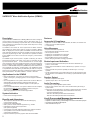
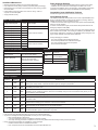
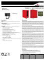
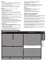
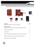
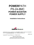
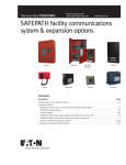
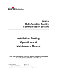
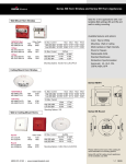
Notification
SPMNS
SAFEPATH® Mass Notification System & Expansion Options
SAFEPATH® Mass Notification System (MNS)
Page 2
SAFEPATH® MNS Microphone
Page 4
POWERPATH™ Notification Appliance Circuit (NAC)
Power Supplies
Page 4
SPMNS
Expansion Options
SAFEPATH® Audio Boosters
Page 6
SAFEPATH® 2-Zone Class A or 4-Zone Class B
Speaker Audio Splitter
SPMNS-MIC
Page 6
PS-6 & PS-8
SPB-80/4, SPB-160, SPB-320
SPAZ-A/B
UL
®
S5361
Notification
SAFEPATH® Mass Notification System (SPMNS)
Description
Cooper Notification’s SPMNS is an In-Building MNS for fire alarm, emergency
communications and voice evacuation with 24 VDC battery back up. It
provides personnel and building occupants with clear, concise and intelligible
voice messages that communicate how people should respond to a variety
of emergency situations.
The SPMNS, which meets UL 2572 requirements for MNS, interfaces
with a building fire alarm system (FAS) to provide a complete In-Building
MNS. An integral part of the fire system, the SPMNS controls all audio and
visual notification appliances for both fire and MNS and reports trouble and
supervisory signal through the FAS. Supervised voice speakers controlled
by the SPMNS can be used for both fire and emergency communication
applications.
The SPMNS single channel system is capable of delivering 40 watts of
supervised high fidelity audio power and 2 amps of supervised 24 VDC
synchronized strobe power. It comes standard with an on-board digital
voice messaging system with 8 standard messages, a hand-held microphone
for fire messages, power supply/battery charger and numerous additional
features. A dedicated MNS microphone (SPMNS-MIC) will be utilized for live
voice messages for emergency communications. The SAFEPATH system
is expandable to 5280 watts utilizing the SPB-80/4 (80 watts and 4 amps of
strobe power), the SPB-160 (160 watts) or SPB-320 (320 watts) supervised
audio power boosters. All models available in 115 VAC or 220 VAC.
Applications for the SPMNS
• Multi-use applications—The system can function as an evacuation
system, an emergency messaging system, and an employee notification
system
• Fire code applications—The system is listed under UL 2572 for MNS, UL
Standard 864, 9th edition delivering supervised audio and voice
messaging with strobes and notification appliance circuits (NAC) for
visual alerting
• Economic OSHA applications—The system is OSHA 1910.165 compliant;
this means that it does not require reliability inspections every two
months, or the required spare parts inventory
• Wide ranging applications—from small to large facilities
System Activation
• Contact closure message activation
Benefits and Advantages
• One Supervised, Multi-Function, Voice Fire Alarm/Emergency
Communications System
• Interfaces with addressable FAS
• Built in power for visual notification appliances e.g., Strobes
• Expandable for larger system requirements
(with optional equipment)
• Controls audio and visual notification appliances for both fire and MNS
• Voice speakers can be used for both fire and emergency
communication applications
• Reports trouble and supervisory signal for both the FAS and MNS.
2
SPMNS
Features
Approvals & Compliance
• Approvals: UL 2572 for MNS, UL Standard 864, 9th edition, UL Standard 1711
• OSHA 1910.165 and ADA Compliant
• 1 Year Warranty
Voice Messages
•
•
•
•
•
•
•
Complies to NFPA-72 requirements
Supervised NAC speaker and strobe circuits
Live microphone override
5 digitally pre-recorded MNS voice messages
3 digitally pre-recorded fire voice messages
User selectable pre-tones for fire messages
Flexible, field-programmable messaging capabilities
Strobe Inputs and Activation
• 2 Amps of 24 VDC supervised strobe power with built-in Wheelock sync
protocol. Power limited.
• Strobe output is selectable for control of Wheelock sync protocol or non-sync
operation
• Strobe terminals have pass thru capability for Wheelock sync or non-sync
operation
• 24 VDC supervised and synchronized strobe power can be expanded to meet
the requirements of the installation via connecting to optional Wheelock power
boosters
Speaker Output
• 40 watts of supervised audio power
• Speaker outputs: 25V or 70.7V power limited
Audio Processing
• Connectivity of optional speaker splitter modules
• Dual-tone tone generator with: Code 3 Tone and Slow Whoop for alerting of
system trouble
• Audio power can be expanded by connecting to optional audio power boosters
- SPB-80/4 80 Watt Supervised Audio Power Booster with 4 Amp
of Synchronized Strobe Power
- SPB-160 160 Watt Supervised Audio Power Booster
- SPB-320 320 Watt Supervised Audio Power Booster
Live & Pre-recorded Message Announcement
•
•
•
•
Supplied with 8 pre-recorded emergency messages
Capable of in-field recording of all messages via 1/8” line level audio input jack
On board Push-to-Talk Fire Microphone
Dedicated MNS Microphone
Installation/Maintenance
• Multiple trouble LED indicators for quick system diagnostics
• Fully supervised circuitry always in effect (via patent pending technology)
• Removable quick connect/disconnect terminals for ease of wiring, accepts
#12 to #22 AWG
• Power limited circuitry with Class “B” or Class “A” wiring. Class “A”
only with use of Audio Splitter
• Surge protected circuitry
Power Supply & Batteries
• 24 VDC, 33AH Max rechargeable battery back-up power circuitry built-in
• Batteries can be housed in the enclosure(Up to two BAT-1212, 12 volt,
12 ampere hour batteries can fit in the enclosure). Actual battery size required
will depend on speaker and/or strobe load. Batteries are sold separately.
Compatible Cooper Notification Products
All Wheelock Appliances Wheelock Strobe Power Supply
Voice Message Priority
The SPMNS will override the FAS with live voice from a separate MNS microphone or manual activation of a high-priority emergency message. After the
SPMNS relinquishes control, the following occurs:
1. Without an active fire alarm signal, the fire alarm system shall automatically
restore to normal operation
2. With an active fire alarm signal, the fire alarm shall operate based on the
Emergency Response Plan (ERP)
Inputs – Audio and Activation
Priority Ordered Inputs
Priority
Level
Auxiliary Microphone
1
Digital Message Input 1
2
Digital Message Input 2
3
Digital Message Input 3
4
Digital Message Input 4
5
Digital Message Input 5
6
On Board Microphone
7
Digital Message Input 6
8
Digital Message Input 7
9
Digital Message Input 8
10
Type of Input
MNS Microphone
The fire alarm signal deactivation function occurs only when both the FAS is in
alarm condition and an MNS voice message is initiated by the SPMNS. When
the fire alarm notification is overridden by the SPMNS priority emergency message, all other features of the FAS remain unaffected.
Contact Closure activation
Priority messaging is as follows:
- Live voice messages from the MNS microphone
- Pre-recorded prioritized mass notification messages
- Live voice messages from the fire microphone
- Pre-recorded fire messages
Fire Microphone
Contact Closure activation
Audio/Technical Specifications
Mechanical
Switch mode, Class D amplifier (40 Watts)
Dimensions
21” H x 16” W x 6” D
(wall mount)
Weight
36 lbs.
(without batteries)
Finish
Red exterior enclosure
Door Lock
Key-lock
Speaker Outputs
25V or 70.7V power limited
Frequency Response
Voice: 275 Hz – 6.5 kHz
Meets UL Voice Evacuation
Requirements of 800 - 2800 Hz
Signal to Noise Ratio
better than 65 dB
Dynamic Range
better than 65 dB
Total Harmonic Distortion
less than 2%
Stand by Current Draw
130 mA
Alarm Current Draw
4.7 amps
Message Capabilities
Message and
Priority #
MNS/Fire
Voice
Type
1
MNS
Male
Three (3) seconds of 1kHz of tone (followed by): ATTENTION: There is an emergency in the building. Evacuate the
building in an orderly fashion. Follow all instructions given by emergency responders.
2
MNS
Male
Three (3) seconds of 1kHz of tone (followed by): ATTENTION: A severe weather conditions exist – Seek shelter
immediately until further notice.
3
MNS
Male
Three (3) seconds of 1kHz of tone (followed by): ATTENTION: Hazardous Material Warning; Shut down all heating,
ventilation, and air conditioning systems; Seek cover immediately away from doors and windows. Stay where you are
until contacted by local authorities.
4
MNS
Female
ATTENTION: The building emergency has ended. An all clear has been given. Please resume normal activities.
5
MNS
Female
ATTENTION: There is an on-going situation in the building. Please listen for further announcements and remain safe
until further notice.
6
Fire
Male
May I have your attention please! A fire emergency has been reported in the building. While this is being verified,
please leave the building by the nearest exit. Do not use the elevators.
7
Fire
Male
May I have your attention please! A fire emergency has been reported in the building. While this is being verified, please
leave the building by the nearest exit. Do not use the elevators.
8
Fire
Male
Five (5) seconds of 1kHz tone (followed by). May I have your attention please! This is a test of
the Mass Notification System, repeat, this is only a test.
Message Script
• Each message can be selected to have a code 3 pre-alert tone, a 1kHz continuous pre-alert tone, or no pre-alert tone
• Post-tones are also selectable and match the pre-tones for individual messages
• Any of the 8 messages are field programmable to record your own custom message
• Each message length is 30 seconds
• A 1/8” line level audio input jack is supplied for message recording
• A two step recording procedure is required to ensure and verify that the standard message will be permanently erased
• Factory programmed messages are available for custom messages
• Contact customer service for additional information
• Form is required and can be downloaded from www.coopernotification.com
3
Notification
POWERPATH™ NAC POWER SUPPLIES
SAFEPATH®
MNS Microphone
SPMNS-MIC
PS-EXP
PS-6
Description
Description
MNS Microphone for use with the SAFEPATH Mass Notification System SPMNS
Applications
•
PS-8
Provides dedicated microphone for mass notification and emergency
communications applications
Features
•
Approvals: UL 2572 for MNS, UL Standard 864, 9th edition and
California State Fire Marshal (CSFM)
•
UFC 04-021-01 Compliant
•
Supervised hand held push to talk microphone
• Key required to enable microphone use
• Individual front panel LED indication for; System
Normal, System Trouble and Alarm
• When used with the SPMNS, the priority level of the SPMNS-MIC is 1,
the SPMNS on-board fire microphone is a lower priority
• Voice frequency response: 275 Hz - 6.5 kHz
• Requires 24VDC, supplied by the SPMNS, Audio
Boosters, or SP4-RMX
• Input current: Standby: 23mA
Alarm: 30mA
• Audio output level: 1.05V RMS
• 6 wire connection to the SPMNS
• Mounting plate is black and measures, 8 3/4” x 5 ¼”, fits into a 4 gang
back box
• All output circuitry is Power Limited
Cooper Notification’s POWERPATH Power Supplies PS-6 and PS-8 are 24VDC,
filtered and regulated, supervised remote power supplies/battery chargers. Used
for supervision and expanded power driving capability of Fire Alarm and Mass
Notification Appliance Circuits, PS-6 provides 6 amps of power distributed across
4 outputs, while the PS-8 provides 8 Amps across 4 outputs. In addition, the
PS-8 provides additional room in the chassis for accessories like an Addressable
Control Module, with mounting studs.
The Power Supplies may be connected to any 12V or 24V (FWR or DC) Fire
Alarm Control Panel (FACP) by using a Notification Appliance Circuit (NAC) or
a “Dry Contact”. Primary applications include NAC expansion (supports ADA
requirements) and auxiliary power to support system accessories. This unit
provides filtered and regulated 24VDC, up to four (4) Class “B”, two (2) Class
“A”, or two (2) Class “B” and one (1) Class “A” Notification Appliance Circuits.
With the optional plug-in PS-EXP module the unit supports (8) Class “B” or (4)
Class “A” Notification Appliance Circuits. Additionally, an auxiliary power output
of 2.5 Amps (disconnected upon AC power loss or an alarm condition) or up to
0.240 A of constant power on the PS-8 .
The Wheelock Power Supply can accommodate 7 or 12 AH batteries inside its
lockable chassis. Using an external battery cabinet, it can charge up to 33 AH
batteries (pending UL testing). Two FACP NAC circuits or two “Dry” contact
initiating circuits can be connected to the inputs. These inputs can then be
directed to control supervision and power delivery to any combination of the
four (4) outputs. Each output is rated at 3.0 Amps (Class “B”) or (Class “A”) and
can be programmed to generate a steady or Code 3 Temporal Horn sound and
a strobe output under alarm condition. Total load for PS-8 NAC circuits must not
exceed the power supplies rated output.
The Power Supplies under non-alarm condition provides independent supervision
for Class “A” and Class “B” FACP NAC circuits. In the event of circuit trouble,
the FACP will be notified via the POWERPATH steered input (IN1 or IN2). In
addition there are two sets of trouble reporting terminals, one used for AC power
loss reporting and the other for all troubles. The AC power loss reporting, on
the common trouble terminals and on IN1 or IN2, can be delayed for either 30
seconds or 170 minutes. The AC power loss terminals will always report the
trouble within 1 second after loss of AC power.
The PS-6 and PS-8 Power Supplies are UL Listed under UL 2572 for MNS
and UL Standard 864, 9th Edition to be used with any 24 volt listed regulated
notification appliances. They include the capability to synchronize Wheelock
strobes and horns and to silence the horn signal when horn/strobes are operating
on two wires.
Approvals
UL
®
THE CITY OF
NEW YORK
DEPARTMENT OF BUILDINGS
151.92-E
4
• Approvals Include: UL 2572 for MNS, UL Standard 864,
1481, California State Fire Marshal (CSFM), Factory Mutual (FM)
• Pending: New York City (MEA), Chicago (BFP) See Approvals by
model in Specification and Ordering Information
• Compliant with NFPA 72
Model
Dimensions
Weight
Comments
PS-6/PS-6B
17”H x 13”W x 3.5”D
11.5lbs (Ship) 9.4lbs (Unit)
Small profile
PS-8
17”H x 15”W x 5.5”D
17.7lbs (Ship) 15.6lbs (Unit)
Additional room for modules
PS-EXP
4.3”H x 3.7”W x 1”D
1lb. (Ship & Unit)
Plugs into main pcb on all models
Inputs
• 120VAC, 50/60Hz, 4.25 Amps and 5.32 Amps Operating Power in Alarm
• 240VAC, 60Hz, 3.22 Amps (PS-8E) Operating Power in Alarm
• 24VDC Battery Backup Connection
• Two (2), 12V or 24V NAC Initiating Circuits (8-33V at 5mA) FWR or DC
• Two (2) “Dry” Contact initiating Circuits
• Accepts two (2) Class “A” or two (2) Class “B” circuit inputs
• Built in battery charger for sealed lead acid or gel type batteries
Outputs
• NAC outputs are 24VDC, 3.0 Amps each, power limited
• 8 Amps on total alarm current
• Capable of four (4), Class “B” circuits
• Capable of two (2) Class “A” circuits
• Capable of one (1) Class “A” circuit and two (2) Class “B” circuits
• Capable of (8) Class “B” or four (4) Class “A” circuits with optional
PS-EXP module
• Temporal (Code 3), constant voltage output, Wheelock Sync output or
True input to output follower mode
• Built-in Wheelock synchronization mode that can be fed to any or all of
the output circuits
• Input and output can be synchronized with “IN>OUT SYNC” mode
(SM, DSM, 2nd POWERPATH™ or FACP with synchronization protocol is required)
• Audible silence capability
• Filtered and electronically regulated output
• 2.5 Amp auxiliary power limited output with reset capability
(Removed upon AC loss or alarm. Automatic reset 30 seconds after
AC power returns or the alarm condition is over) 0.240 Amps of auxiliary
power limited output which remains on during AC loss or an alarm
condition when configured for 24 hour battery backup
Supervision
• Compatible with 12V or 24V (FWR or DC) FACP
• Signaling appliance circuits are supervised and steered to either IN1 or IN2
• 10K Ohm, 1 Watt (Wheelock Model #MPEOL) End of Line Resistor
(EOLR) for supervision of all outputs
• 37 distinguishable trouble diagnostics
• AC loss trouble reported over a separate set of contacts (delay of 1 second)
• All troubles are reported over the common trouble contacts (AC loss
can have a delay of 30 seconds or 170 minutes)
• Automatic switchover to standby battery when AC fails
• Thermal and short circuit protection with auto reset
• Input and output status LED indicators
• AC fail supervision
• Battery presence and low battery supervision
• Ground Fault Detection, with diagnostics to indicate which circuit fault is on
• Latching LED’s for NAC trouble annunciation and Diagnostic
trouble LED’s (latching can be disabled)
Power
• Not Battery Dependent
• Automatic switch over to standby batteries when AC fails
• Supports sealed lead acid or gel type batteries
• Fused battery protection
• Thermal and short circuit protection with auto reset
• Supports both 7AH or 12AH batteries in the same cabinet
POWERPATH™ Operating Modes
(refer to Installation Manual):
Normal Mode: Provides constant 24 VDC output upon initiation by a voltage
to input IN1 or IN2 or by a contact opening on DRY1 or DRY2. The unit
returns to standby mode when the input is deactivated.
Wheelock Sync Mode: Provides signals for synchronization of patented
Wheelock audible and strobe notification appliances. Audibles can also be
silenced in this mode while the strobes continue to flash.
In>Out Sync Mode: Accepts a synchronization signal on the input to provide
a coded output or synchronized output. This signal may come from a FACP,
another POWERPATH or a Wheelock SM or DSM synchronization module.
Caution: Do not use strobes on coded output circuits.
True Input Follower Mode: Accepts a coded signal on the input to provide
a coded output with the same timing as the input. The signal may come
from a FACP, another POWERPATH or other coded source. Caution: Do
not use strobes on coded output circuits.
Temporal Mode: Codes the output voltage in a code-3 temporal pattern to
drive audible appliances such as horns, bells or chimes. Caution: Do not
use strobes on coded output circuits.
Specifications and Ordering Information
Model Number
Approvals
Order Code
Input Voltage/Current
UL
CSFM
PS-6
105530
6 Amp, red enclosure
X
X
PS-8
105531
8 Amp, red enclosure
X
X
PS-6EXP
105083
6 Amp power supply with preinstalled expansion module
X
X
PS-8EXP
106084
8 Amp poswer supply with preinstalled expansion module
X
X
PS-EXP
PS-EXP-RETRO
Input Circuit
105534
105527
4 class B or 2 class A expansion module
Field upgrade kit for models prior to January 2010#
Input Voltage and Current
X
X
X
X
Input voltage Range
8 to 33 VDC
Input Current @ 12 VDC
0.005 Amps
Input Current @ 24 VDC
0.005 Amps
Output Circuit
Output Voltage and Current
Four (4) Class B or
Two (2) Class A or
24 VDC @ up to 3 amps per curcuit
One (1) Class A and Two (2) Class “B” or
8 Class B or 4 Class A (optional PS-EXP module necessary)
X= Approved
*= Pending
#=Contact
Technical
Support for
additional
inforamation
on upgrade
options
Continuous duty up to 3 Amps per circuit, up to 4 Amps maximum per panel
0.129 Amps
Standby Current
Alarm Current
0.129 Amps
Primary PS-6 (120 VAC models)
105 to 130 VAC, 50/60 Hz @ 4.25 Amps
Primary PS-8 (120 VAC models)
105 to 130 VAC 50/60 Hz @ 5.32 Amps
Primary PS-8E (240 VAC models)
Secondary Power Charging Capacity
210 to 260 VAC 50/60 Hz @ 3.22 Amps
32 Amp hours @ 0.750 Amps per hour
Enclosure can house up to two 12 AH batteries
Aux Output
CP Mode
MP Mode
PS-8 up to 250 mA
2.5A during non alarm
5
Notification
SAFEPATH®
2-Zone Class A or 4-Zone Class B
Speaker Audio Splitter
SAFEPATH® Audio Boosters
SPB-320 - 320 Watt Supervised Audio Power Booster (Four 80
watt circuits)
SPB-160 - 160 Watt Supervised Audio Power Booster (Two 80
watt circuits)
SPB-80/4- 80 Watt Supervised Audio Power Booster with 4
SP4Z-A/B
Amps of Supervised and Synchronizable Strobe Power (Two 2
Amp circuits)
SPB-320
SPB-80/4
SPB-160
Description
Supervised 2-Zone Class A or 4-Zone Class B Speaker Audio Splitter for the
SPMNS or Audio Boosters. Enables a single supervised speaker audio output
to drive up to two Class A supervised speaker audio outputs or four Class B
supervised speaker audio outputs.
Applications
• • Provides for expansion of one zone to up to 2 zones of supervised
speaker audio output in Class A
Provides for expansion of one zone to up to 4 zones of supervised
speaker audio output in Class B
Features
•
•
•
•
•
•
•
•
•
•
•
•
•
•
•
•
Approvals: UL 2572 for MNS, UL Standard 864, 9th edition, and
California State Fire Marshal (CSFM), New York City (MEA)
UFC 04-021-01 Compliant
Expands one zone to up to 2 zones of supervised speaker audio
output in Class A
Expands one zone to up to 4 zones of supervised speaker audio
output in Class B
Each Class A zone can accept up to 40 watts of audio
Each Class B zone can accept up to 40 watts of audio
Operates on either 25V or 70.7V RMS
Mounts inside the enclosure of the SPMNS or Audio Boosters
Power and Trouble LED’s
Individual zone short and open LED indication
Capable of detecting wiring faults
Removable wiring terminals for quick connect/disconnect accepting
12–22 AWG
All output circuitry is Power Limited
Space provided to allow for naming of the zones
Powered by 24VDC, supplied by the either the SPMNS or Audio
Boosters
Standby and Alarm current at 24VDC is 15mA
Description
Supervised Facility Communication and Emergency Voice Evacuation Audio and
Audio/Strobe Power Boosters, UL 2572 for MNS, UL Standard 1711 and UL Standard
864, 9th edition with 24VDC battery backup capabilities. Designed to provide for
additional supervised audio power for live voice or pre-recorded messages. Fully
supervised patent pending circuitry is always in effect. The SPB-80/4 also provides
4 Amps of 24 VDC Supervised and Synchronized Strobe Power.
The SPB-320, SPB-160 and the SPB-80/4 easily connects to the Cooper Notification
SPMNS. Multiple SPB-320, SPB-160 and SPB-80/4 Audio Boosters can be interconnected to accommodate large installations with supervised audio power and
also supervised and synchronized strobe power requirements.
The SPB-320 draws 2.4 watts of audio input power to properly operate and provide
additional supervised audio output power. The SPB-160 and the SPB-80/4 draws
1.2 watts of audio input power to properly operate and provide additional supervised
audio output power. A maximum of 5,280 watts of supervised audio power can be
achieved. Additional strobe power can be obtained via a combination of SPB-80/4
or Wheelock Power Supplies/Chargers.
Applications
•
•
•
Provides for additional supervised audio power for large installations
Provides for additional supervised and synchronizable strobe power for
large installations
Can be used in new construction as well as in retrofit construction
Features
Approvals & Compliance
•
•
•
Approvals: UL 2572 for MNS, UL Standard 864, 9th edition, UL Standard 1711, California State Fire Marshal (CSFM), New York City (MEA)
OSHA 1910.165, ADA and UFC 04-021-01 Compliant
1 Year Warranty
•
•
70V or 25V input from the SPMNS
1 Volt input from SP4-RMX
•
8 - 33VDC NAC input connected to the strobe input
System Activation: Audio
System Activation: Strobe (SPB-80/4)
6
Power Supply & Batteries
•
•
•
•
•
•
•
Fully supervised patent pending circuitry always in effect
Power limited circuitry
Class D amplifiers
Internal battery charger and power supply Required batteries fit inside the enclosure (sold separately)
SPB-320 requires four 12 VDC, 12 AH batteries
SPB-160 and SPB-80/4 require two 12 VDC, 12 AH batteries
Outputs
•
•
•
•
•
•
SPB-320 has four 80 watt speaker output circuits
SPB-160 has two 80 watt speaker output circuits
SPB-80/4 has one 80 watt speaker output circuit and two 2 amp
strobe circuits (4 amps total)
Supervised Audio Speaker outputs: 70V or 25V field selectable (all
boosters must be either 70 V or 25 V)
Expansion output (supervised, 24VDC at .5A in alarm condition
used for connecting multiple boosters
DC output (unsupervised for optional splitter power). Each speaker
circuit (four for the SPB-320, two for the SPB-160, one for the SPB-80/4)
can connect to speaker splitters
SPB-80/4 Strobe Features
•
•
•
•
Two 24VDC 2 Amps, NAC supervised, synchronizable, power
limited, Class B strobe outputs
Selectable outputs: Wheelock sync, pass through, or constant DC
Trouble LED’s for open and short output conditions
Alarm indicator: LED’s for Strobe and Expansion Outputs
Inputs
•
•
Audio Speaker Inputs: 70V or 25V, field selectable
Auxiliary in (for alarm input signal)
Mechanical
SPB-160, SPB-80/4
•
•
•
•
Dimensions: 21” H x 16” W x 6” D (wall mount)
Weight:
36 lbs. (without batteries)
Finish: Red exterior enclosure
Door Lock:
Wheelock key-lock
SPB-320
•
•
•
•
Dimensions: 36” H x 24” W x 6” D (wall mount)
Weight:
80 lbs. (without batteries)
Finish:
Red or black exterior enclosure
Door Lock:
Wheelock key-lock
Technical Specifications
•
120VAC, 3.8A, 60 Hz input
•
SPMNS Models 240 VAC, 2.5A, 50-60 Hz
•
Standby current draw:
120mA per amplifier board
•
Alarm current draw:
9 Amps per amplifier board
SPB-80/4 and SPB-160 have one amplifier board
SPB-320 has two amplifier boards
•
System Frequency Response:
Voice 400 Hz - 6.5 kHz
•
Removable quick connect/disconnect terminals, accept 12 - 22 AWG
•
Multiple LED’s for easy indication of system diagnostic conditions
•
Signal to Noise Ratio: > 70 dB
•
Dynamic Range: > 65 dB
•
Total Harmonic Distortion: 2%
Note: The Speaker Splitter-Mounting Bracket (SPMB4Z) is
required when the Speaker Splitter is used in Audio Boosters.
The SPMB4Z can support two splitters.
Wheelock products must be used within their published specifications and must be PROPERLY specified, applied, installed, operated, maintained and
operationally tested in accordance with their installation instructions at the time of installation and at least twice a year or more often and in accordance
with local, state and federal codes, regulations and laws. Specification, application, installation, operation, maintenance and testing must be performed
by qualified personnel for proper operation in accordance with all of the latest National Fire Protection Association (NFPA), Underwriters’ Laboratories
(UL), National Electrical Code (NEC), Occupational Safety and Health Administration (OSHA), local, state, county, province, district, federal and other
applicable building and fire standards, guidelines, regulations, laws and codes including, but not limited to, all appendices and amendments and the
requirements of the local authority having jurisdiction (AHJ).
NOTE: Due to continuous development of our products, specifications and offerings are subject to change without notice in accordance with Cooper
Wheelock, Inc. dba Cooper Notification standard terms and conditions.
Note: Refer to the products Installation Instructions for proper installation, wiring procedures and any additional specifications.
7
SYSTEM COMPONENTS
Fire/M
FIRE MICROPHONE
SP
SPMNS
Addressable FACP
ALERT
PS-8
Fire Alarm / MNS Solution
8
ALERT
A
Notification
EXPANSION OPTIONS
MNS Speakers
SPB-160
Fire/MNS Speakers
SPB-320
PMNS-MIC
ALERT
Cluster Speaker
Fire
PS-8
Strobes
Fire
MNS
Strobes
ALERT
ALERT
ALERT
MNS
Some devices here may not meet UL Standards for MNS. Consult your Cooper Notification Sales
Manager for details.
9
Notification
Ordering Information
Model Number
Description
SPMNS
In-Building Mass Notification, Messaging, and Emergency Voice Evacuation System with 24 VDC battery backup circuitry.
Single channel system with 40 watts of supervised audio power and 2 amps of supervised 24 VDC synchronized strobe
power and 8 standard message, (Batteries not included, 2 required) red enclosure
SPB-320
320 Watt Supervised Audio Power Booster (Four 80 watt circuits)
SPB-160
160 Watt Supervised Audio Power Booster (Two 80 watt circuits), red enclosure
SPB-160-B
160 Watt Supervised Audio Power Booster (Two 80 watt circuits), black enclosure
SPB-80/4
80 Watt Supervised Audio Power Booster with 4 Amps of Supervised and Synchronized Strobe Power (Two 2 Amp
circuits), red enclosure
SPB-80/4-B
80 Watt Supervised Audio Power Booster with 4 Amps of Supervised and Synchronized Strobe Power (Two 2 Amp
circuits), black enclosure
SP4Z-A/B
Supervised 2-Zone Class A or 4-Zone Class B Speaker Audio Splitter for the SPMNS, SP40/2, SPB-320, SPB-160 or
SPB-80/4
SPMB4Z
Speaker Splitter Mounting Bracket for SPB-320, SPB-160 or SPB-80/4
SPMNS-MIC
Mass Notification Microphone for use with the SPMNS, black plate
PS-6
6 Amp Supervised Remote Power Supply, 24VDC
PS-8
8 Amp Supervised Remote Power Supply, 24VDC
BATC-R
Battery Cabinet, Red
BATC-B
Battery Cabinet, Black
BAT-1212
12 Volt, 12 Ampere Battery Cell
BAT-1224
12 Volt, 24 Ampere Battery Cell
BAT-1265
12 Volt, 65 Ampere Battery Cell
10
Architects and Engineers Specifications
SAFEPATH® Mass Notification System
The system shall be a multi-purpose NFPA compliant, supervised, fire/emergency communications system and shall interface with a building fire alarm system
(FAS) to provide a complete In-Building MNS. The system shall control all audio and visual notification appliances for both fire and MNS and report trouble and
supervisory signal through the FAS. The system shall be capable of delivering 40 watts of supervised audio power and 2 amps of supervised 24 VDC synchronized
strobe power. Minimum supervised audio power shall be 40 watts, expandable to 5280 watts, depending on system configuration and with additional modules
and power boosters. Supervised 24 VDC synchronized strobe power shall be 2 amps, expandable to the requirements of the installation. The system shall be
capable of operating from a 120 VAC power source. SPMNS shall be capable of operating from a 240 VAC power source. All models shall have a 24 VDC
battery backup. Standard on-board system features shall include: digital voice messaging, a hand-held push-to-talk microphone with override priority, and a power
supply/battery charger. Form C contacts shall be provided for system alarm and trouble conditions.
The system shall have 8 message contacts with contact closure activation. The system shall have 10 priority ordered inputs, including: On Board Microphone,
Auxiliary Input (Line Level), and 8 Digital Messages. The system shall have preset audio levels for emergency messaging (prerecorded and live mic). The
system shall be supplied with 8 pre-recorded messages and be capable of in-field recording of customer unique messages. The system shall have a dual-tone
tone generator with Code-3 Tone and Slow Whoop.
The panel shall have power-limited circuitry with an internal battery charger and power supply. The power supply/charger section shall be able to charge 24 VDC
batteries with a maximum capacity of 33 amp hours. Up to two 12 VDC, 12 AH batteries may be housed in the enclosure. Batteries larger than 12 Ah shall be
housed in a separate enclosure such as the Cooper Wheelock BATC or equivalent. Batteries shall be supplied separately.
The system shall have power limited circuitry and class B wiring. Wiring terminal blocks will be removable and accept #22 - #12 AWG wire. Audio output voltage
shall be selectable for 25V or 70.7V. The voice (live microphone or recorded message) frequency response shall be 275 Hz – 6.5 kHz. Stand by current draw
shall be 140mA. Alarm current draw shall be 4.7 amps. The signal to noise ratio shall be better than 65 dB, dynamic range shall be better than 65 dB, total
harmonic distortion shall be less than 2%.
The system shall be wall mountable, enclosed in a steel locking enclosure. The required batteries for 40-watt systems shall fit inside the enclosure. The 40 watt
system shall weigh no more than 36 lbs (without batteries) and its dimensions shall not exceed 21” H x 16” W x 6” D. Approvals for the system shall include: UL
Standard 864, 9th edition, UL 2572 for MNS, and UL Standard 1711. The system shall be OSHA 1910.165, and ADA compliant. 1 Year Warranty.
Wheelock POWERPATH™ Series PS-6
The power supply shall be Wheelock POWERPATH™ Series PS-6, or equivalent. The unit shall be stand alone power supply intended for powering fire alarm
notification appliances via its own Notification Appliance Circuit(s) (NAC). The unit shall be UL 2572 for MNS and UL 864 Listed for power limited operation of
outputs and comply with NFPA 70 (NEC), article 760.
The power supply shall support a full 6A of notification power even if the battery is in a degraded mode and only AC power is connected.
The power supply shall be activated by a standard Notification Appliance Circuit (NAC) from any Fire Alarm Control Panel (FACP) or a“Dry contact” opening. The
units shall be 6 ampere, 24 VDC, regulated and filtered, supervised remote power supply/charger. It shall operate over the voltage range of 8 to 33 VDC or FWR.
The primary application of the unit shall be able to expand fire alarm system capabilities for additional NAC circuits to support ADA requirements and to provide
auxiliary power to support system accessories or functions. The power supply shall provide four Class “B”, two Class “A”, or two Class “B” and one Class “A”
NAC circuit(s). Eight Class “B” or Four Class “A” circuits shall be available with an optional PS-EXP module. The PS-6 unit shall supply up to 200 mA of auxiliary
power that is available during both non-alarm and alarm or auxiliary power of not less than 2.5A at 24 VDC during non-alarm.The power supply shall be capable
of charging batteries of up to 33 ampere hours per NFPA 72 at a maximum rate of 0.750 Amps per hour.
Input activation options shall be from not less than two NAC circuits or Dry Contact closures. These inputs shall have the capability ofbeing directed to any
combination of the four NAC circuit outputs. Each NAC circuit output shall be rated at 3 amperes for Class “B”applications or 3 amperes each for Class “A”. The
outputs shall be programmable to generate a steady or Temporal (Code 3) outputand or a synchronized strobe or horn output. The power supply shall provide
independent loop supervision for either Class “A” or Class “B” FACP NAC circuits and shall have the capability to “steer” all alarm or trouble conditions to either
incoming NAC circuit. The units shall have common trouble terminals. The power supply shall be powered from a 120 VAC source with a current consumption of
xx amperes max. The unit shall incorporate short circuit protection with auto reset. The power supply shall incorporate a built in battery charger for lead acid or gel
type batteries with automatic switchover to battery back up in the event of AC power failure. The charger shall incorporate fused protection for the batteries and
have the ability to report low battery and/or no battery condition(s). Standby current for battery back up shall be 0.130 Amps max. The power supply shall have
the ability to latch trouble LED’s so the circuit in trouble can be identified. The cabinet dimensions shall be 17” H x 13” W x 3.5” D.
Wheelock POWERPATH™ Series PS-8
The power supply shall be Wheelock POWERPATH™ Series PS-8, or equivalent. The unit shall be stand alone power supply intended for powering fire alarm
notification appliances via its own Notification Appliance Circuit(s) (NAC). The unit shall be UL 2572 for MNS, UL 864 Listed for power limited operation of outputs
and comply with NFPA 70 (NEC), article 760.
The power supply shall support a full 8A of notification power even if the battery is in a degraded mode and only AC power is connected.
The power supply shall be activated by a standard Notification Appliance Circuit (NAC) from any Fire Alarm Control Panel (FACP) or a “Dry contact” opening.
The units shall be 8 ampere, 24 VDC, regulated and filtered, supervised remote power supply/charger. It shall operate over the voltage range of 8 to 33 VDC
or FWR. The primary application of the unit shall be able to expand fire alarm system capabilities for additional NAC circuits to support ADA requirements and
to provide auxiliary power to support system accessories or functions. The power supply shall provide four Class “B”, two Class “A”, or two Class “B” and one
Class “A” NAC circuit(s). Eight Class “B” or Four Class “A” circuits shall be available with an optional PS-EXP module. The PS-8 unit shall supply up to 240 mA
of auxiliary power that is available during both non-alarm and alarm or auxiliary power of not less than 2.5A at 24 VDC during non-alarm. The power supply shall
be capable of charging batteries of up to 33 ampere hours per NFPA 72 at maximum rate of 0.750 Amps per hour.
Input activation options shall be from not less than two NAC circuits or Dry Contact closures. These inputs shall have the capability of being directed to any
combination of the four NAC circuit outputs. Each NAC circuit output shall be rated at 3 amperes for Class “B” applications or 3 amperes each for Class “A”. The
outputs shall be programmable to generate a steady or Temporal (Code 3) output and or a synchronized strobe or horn output. The power supply shall provide
independent loop supervision for either Class “A” or Class “B” FACP NAC circuits and shall have the capability to “steer” all alarm or trouble conditions to either
incoming NAC circuit. The units shall have common trouble terminals. The power supply shall be powered from a 120 VAC source with a current consumption of
xx amperes max. The unit shall incorporate short circuit protection with auto reset. The power supply shall incorporate a built in battery charger for lead acid or
gel type batteries with automatic switchover to battery back up in the event of AC power failure. The charger shall incorporate fused protection for the batteries
and have the ability to report low battery and/or no battery condition(s). Standby current for battery back up shall be 0.129 Amps max. The power supply shall
have the ability to latch trouble LED’s so the circuit in trouble can be identified. The cabinet dimensions shall be 17” H x 15” W x 5.5” D.
11
Architects and Engineers Specifications
SAFEPATH MNS Microphone
The Mass Notification Microphone shall be UL 2572 for MNS, UL Standard 864, 9th edition and California State Fire Marshal (CSFM)
approved for use with the Mass Notification System.
The Mass Notification Microphone shall be a supervised microphone used for live voice emergency communication messages. When used
with the SAFEPATH Mass Notification System, the Mass Notification Microphone shall have the capability to override the fire microphone
and any fire pre-recorded messages. All output circuitry shall be power limited. Multiple on board diagnostic LED indicators shall be
provided. All wiring shall be capable of accepting 12 – 22 AWG wiring.
SAFEPATH® Audio Boosters
The Wheelock SPB-320, SPB-160 and SPB-80/4 Audio Boosters shall be NFPA compliant supervised audio and supervised 24VDC synchronized strobe power
boosters (some models will have supervised 24VDC synchronized strobe booster capability). The booster shall have 24VDC battery backup capabilities. The
booster shall have the capability to be inter-connected to accommodate large installations with supervised audio power and also supervised and synchronized
strobe power requirements. Three versions of the booster shall be made available: SPB-80/4, (80 watts of supervised audio power and 4 amps of supervised
and synchronized strobe power), SPB-160 (160 watts of supervised audio) or SPB-320 (320 watts of supervised audio).
Each booster shall use 1.2 watts of audio input power (The SPB-320 requires 2.4 watts of audio power) to properly operate and provide additional supervised
audio output power. A combination of boosters can be added together to provide for a maximum of 5,280 watts of supervised audio power. Additional strobe
power can be obtained via a combination of boosters. The audio section of the booster shall be connected via a selectable 70V or 25V input from the Cooper
Notification SPMNS. The strobe section of the booster shall be divided into two sections each supplying two Amps of 24VDC, NAC, supervised, synchronizable,
power limited, Class B strobe outputs, with selectable outputs offering Wheelock sync, pass through, or constant DC and can be activated via 8-33VDC NAC
input or contact closure.
The internal battery charger/power supply shall be capable of charging 24 VDC batteries with a maximum capacity of 33 amp hours. The enclosure shall be
capable of housing the correct number of 12 VDC rechargeable batteries (SPB-80/4 (2), SPB-160 (2), SPB-320 (4)) with a maximum capacity of 12 Amp hours.
Batteries with a larger capacity require an external battery enclosure(s) such as the Cooper Notification BATC or equivalent.
The boosters shall have power-limited circuitry and be a class D amplifier with an internal battery charger and power supply. The required batteries (purchased
separately) shall fit inside the enclosure (two 12VDC, 12 AH for the SPB-80/4 or SPB-160 and four 12 VDC, 12 AH for the SPB-320). The booster shall operate
on 120VAC, 3.8A, 50 – 60 Hz input. E model boosters shall operate on 240 VAC, 2.5A, 50 – 60 Hz input. The SPB-80/4 or SPB-160 standby current draw
shall be 120mA and alarm current draw shall be 9 Amps. The SPB-320 consists of two SPB-160’s. Each SPB-160 shall have its own power supply and battery
charger. The voice frequency response shall be 400 Hz – 6.5 kHz +/- 3 dB. Removable quick connect/disconnect terminals that accept 12 -22 AWG shall be
used. Multiple LED’s for easy indication of system diagnostic conditions shall be present on the PC board. The Signal to Noise Ratio shall be > 70 dB, the
dynamic range shall be > 65 dB, the Total Harmonic Distortion spec shall be 2%.
The booster shall be wall mountable, enclosed in a steel locking enclosure, with a red finish. Approvals for the booster shall include: UL 2572 for MNS, UL
Standard 864, 9th edition, UL Standard 1711, CSFM and MEA. The system shall be OSHA 1910.165, ADA and UFC 04-021-01 2002 (including October 2007
Draft) compliant. The booster shall carry a 1 Year Warranty.
The SPB-80/4 & SPB-160 enclosure dimensions are 21” H x 16” W x 6” D and the SPB-320 enclosure dimensions are 36” H x 24” W x 6” D.
4 Zone Class B Speaker Splitter
The Wheelock SP4Z-A/B shall be UL 2572 for MNS, UL Standard 864, 9th edition, California State Fire Marshal (CSFM) and New York City (MEA) approved,
2-Zone Class A or 4-Zone Class B Speaker Splitter for operation with the SPMNS, SP40/2, SPB-80/4, SPB-160 and SPB-320. The SP4Z-A/B shall enable a
single supervised speaker audio output to drive up to two Class A supervised speaker audio outputs or four Class B supervised speaker audio outputs. Each
Class A zone shall be capable of accepting up to 40 watts and operate on either 25 or 70.7V RMS of audio input. Each Class B zone shall be capable of
accepting up to 40 watts of audio and operate on either 25 or 70.7V RMS of audio input. The SP4Z-A/B shall be capable of supporting live microphone and
prerecorded emergency voice evacuation messages.
The SP4Z-A/B shall mount inside the enclosure of the SPMNS, SP40/2, SPB-80/4, SPB-160 and SPB-320 and shall have power and trouble LED with individual
zone short and open LED indication. The SP4Z-A/B shall be capable of detecting wiring faults. The SP4Z-A/B shall be powered by 24VDC, which is to be
supplied by the SPMNS, SP40/2, SPB-80/4, SPB-160 or SPB-320. Standby and Alarm current at 24VDC shall be 15mA. Removable wiring terminals for
quick connect/disconnect accepting 12–22 AWG shall be incorporated. All output circuitry shall be power limited. Space shall be provided to allow for naming
of the zones.
WARNING: PLEASE READ THESE SPECIFICATIONS AND INSTALLATION INSTRUCTIONS CAREFULLY BEFORE USING, SPECIFYING OR APPLYING THIS PRODUCT. FAILURE
TO COMPLY WITH ANY OF THESE INSTRUCTIONS, CAUTIONS AND WARNINGS COULD RESULT IN IMPROPER APPLICATION, INSTALLATION AND/OR OPERATION OF THESE
PRODUCTS IN AN EMERGENCY SITUATION, WHICH COULD RESULT IN PROPERTY DAMAGE, AND SERIOUS INJURY OR DEATH TO YOU AND/OR OTHERS.
NOTE: Due to continuous development of our products, specifications and offerings are subject to change without notice in accordance with
Wheelock Inc. standard terms and conditions.
WE ENCOURAGE AND SUPPORT NICET CERTIFICATION
1 Year Warranty
SPMNS 09/11
NJ Location
273 Branchport Ave.
Long Branch, NJ 07740
P: 800-631-2148
F: 732-222-8707
www.coopernotification.com
Cooper Notification is
12
FL Location
7246 16th Street East, Suite 105
Sarasota, FL 34243
P: 941-487-2300
F: 941-487-2389
VA Location
103 West Broad Street, Suite 500
Falls Church, VA 22046
P: 877-459-7726
F: 703-294-6560
Notification