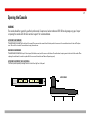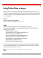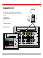
1
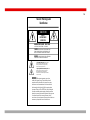
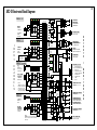
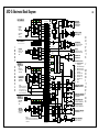
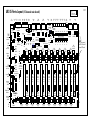
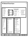
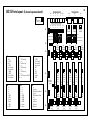
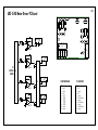
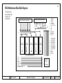
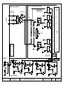
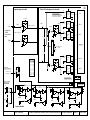
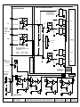
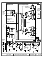
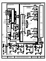
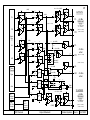
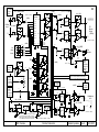
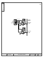
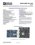
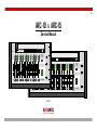
1.1
ARC-10
& ARC-15
Service Manual
ARC-10
Arrakis Systems inc.
Advanced
Radio
Console
Pgm
Pgm
Pgm
Pgm
Pgm
Pgm
Pgm
Pgm
Pgm
Pgm
Aud
Aud
Aud
Aud
Aud
Aud
Aud
Aud
Aud
Aud
Talk
Talk
Cue
Cue
Cue
Cue
Cue
ARC-15
Cue
Cue
Cue
Pgm
Pgm
Pgm
Pgm
Aud
Aud
Aud
Aud
Talk
Cue
Cue
Cue
Cue
Arrakis Systems inc.
Talk to
Caller
Pgm
Monitor & Headphone
Aud
Input Select
Cue
Head
phone
Pgm
Pgm
Pgm
Pgm
Pgm
Pgm
Pgm
Pgm
Pgm
Pgm
Aud
Aud
Aud
Aud
Aud
Aud
Aud
Aud
Aud
Aud
Cue
Cue
Cue
Cue
Cue
Cue
Cue
Cue
Cue
Cue
Advanced
Radio
Console
Cue
Air
Talk to
Caller
Pgm
Aud
Monitor & Headphone
Input Select
Arrakis Systems
Mic 1
Mic 2
Head
phone
Air
Monitor
Pgm
Phone
Aud
Arrakis Systems
Mic
Phone
Rev 1.0.4
ARRAKIS
a d va n c e d r a d i o
Monitor
1.2
How to contact Arrakis Systems
Arrakis Systems inc. is located at
Arrakis Systems inc
6604 Powell Street
Loveland, Colorado
80538
Business Hours:
8:00am - 4:30pm mountain time
Contact:
970-461-0730
970-663-1010
[email protected]
arrakis-systems.com
Voice:
Fax:
email:
web:
Having difficulty contacting Arrakis?
Refer to the website at... www.arrakis-systems.com
for current contact information
ARRAKIS
a d va n c e d r a d i o
1.3
Safety Instructions
1. Read All Instructions. All safety and operating
instructions must be read before operating the
product.
2. Retain All Instructions. All safety and
operating instructions must be retained for
future reference.
3. Heed All Warnings. All warnings on the
product and those listed in the operating
instructions must be adhered to.
4. Follow All Instructions. All operating and
product usage instructions must be followed.
5. Heat. This product must be situated away from
any heat sources such as radiators, heat
registers, stoves, or other products (including
power amplifiers) that produce heat.
6. Ventilation. Slots and openings in the product
are provided for ventilation. They ensure reliable
operation of the product, keeping it from
overheating. These openings must not be
blocked nor covered during operation. This
product should not be placed into a rack unless
proper ventilation is provided through
following the manufacturer’s recommended
installation procedures.
7. Water and Moisture. Do not use this product
near water—for example; near a bath tub, wash
bowl, kitchen sink or laundry tub; in a wet
basement; or near a swimming pool or the like.
8. Attachments. Do not use any attachments not
recommended by the product manufacturer
as they may cause hazards.
9. Power Sources. This product must be
operated from the type of power source
indicated on the marking label and in the
installation instructions. If you are not sure of
the type of power supplied to your facility,
consult your local power company.
10. Grounding and Polarization. This product is
equipped with a polarized AC plug with integral
safety ground pin. Do not defeat the safety
ground in any manner.
11. Power Cord Protection. Power supply cords
must be routed so that they are not likely to be
walked on nor pinched by items placed upon
or against them. Pay particular attention to the
cords at AC wall plugs and convenience
receptacles, and at the point where the cord
plugs into the product.
12. Lightning. For added protection for this
product during a lightning storm, or when it is
left unattended and unused for long periods of
time, unplug it from the AC wall outlet. This will
prevent damage to the product due to
lightning and power line surges.
13. Overloading. Do not overload AC wall outlets,
extension cords, or integral convenience outlets
as this can result in a fire or electric shock hazard.
14. Object and Liquid Entry. Never push objects
of any kind into this product through openings
as they may touch dangerous voltage points
or short-out parts that could result in a fire or
electric shock. Never spill liquid of any kind on
the product.
15. Accessories. Do not place this product on an
unstable cart, stand, tripod, bracket, or table. The
product may fall, causing serious damage to a
child or adult, and serious damage to the
product. Any mounting of the product needs
to follow manufacturer’s installation
instructions.
16. A Product and Cart Combination should be
moved with care. Quick stops, excessive force,
and uneven surfaces may cause the product and
the cart combination to overturn.
17. Servicing. Refer all servicing to qualified
servicing personnel.
18. Damage Requiring Service. Unplug this
product from the wall AC outlet and refer
servicing to qualified service personnel under
the following conditions:
a. When the AC cord or plug is damaged.
b. If liquid has been spilled or objects have
fallen into the product.
c. If the product has been exposed to rain or
water.
d. If the product does not operate normally
(following operating instructions).
e. If the product has been dropped or
damaged in any way.
f. When the product exhibits a distinct change
in performance. This indicates a need for
service.
19. Replacement Parts. When replacement parts
are required, be sure the service technician has
used replacement parts specified by the
manufacturer or that have the same
characteristics as the original parts. Unauthorized
substitutions may result in fire, electric shock, or
other hazards.
20. Safety Check. Upon completion of any repairs
to this product, ask the service technician to
perform safety checks to determine that the
product is in proper operating condition.
21. Cleaning. Do not use liquid cleaners or aerosol
cleaners. Use only a damp cloth for cleaning.
1.4
Hazard / Warning Label
Identification
C AU T I O N
RISK OF
ELECTRIC SHOCK
DO NOT OPEN
WARNING: SHOCK HAZARD - DO NOT OPEN
AVIS: RISQUE DE CHOC ELECTRIQUE - NE PAS OUVRIR
CAUTION: TO REDUCE THE RISK OF ELECTRIC SHOCK DO NOT
REMOVE ANY COVER OR PANEL. NO USER SERVICEABLE PARTS
INSIDE. REFER SERVICING TO QUALIFIED SERVICE PERSONNEL.
WARNING: TO REDUCE THE RISK OF FIRE OR ELECTRIC SHOCK,
DO NOT EXPOSE THE CONSOLE TO RAIN OR MOISTURE.
The Exclamation Point symbol, within an equilateral
triangle, alerts the user to the presence of important
operating and maintenance (servicing) instructions in
product literature and instruction manuals.
The Lightning Flash With Arrowhead symbol, within an
equilateral triangle, alerts the user to the presence of
uninsulated dangerous voltage within the product’s
enclosure that may be of sufficient magnitude to constitute
a risk of electric shock.
WARNING—This equipment generates, uses and can
radiate radio frequency energy. If not installed and used in
accordance with the instructions in this manual it may cause
interference to radio communications. It has been tested and
found to comply with the limits for a Class A computing device
(pursuant to Subpart J of Part 15 FCC Rules), which are designed
to provide reasonable protection against such interference when
operated in a commercial environment. Operation of this equip-ment
in a residential area is likely to cause interference, in which
case the user, at his own expense, will be required to take what-ever
measures may be required to correct the interference.
1.5
Warranty
This console carries a manufacturer‘s warranty subject to the following guidelines and limitations:
A)
Except as expressly excluded herein, Arrakis Systems inc. (“Seller”) warrants equipment of its own manufacture against faulty workmanship
or the use of defective materials for a period of one (1) year from date of shipment to Buyer. The liability of the Seller under this Warranty is limited to
replacing, repairing or issuing credit (at the Seller’s discretion) for any equipment, provided that Seller is promptly notified in writing within five (5)
days upon discovery of such defects by Buyer, and Seller‘s examination of such equipment shall disclose to its satisfaction that such defects existed
at the time shipment was originally made by Seller, and Buyer returns the defective equipment to Seller’s place of business in Loveland, Colorado,
packaging and transportation prepaid, with return packaging and transport guaranteed.
B)
Equipment furnished by Seller, but manufactured by another, shall be warranted only to the extent provided by the other manufacturer.
C)
Thermal filament devices (such as lamps and fuses) are expressly excluded from this warranty.
D)
The warranty period on equipment or parts repaired or replaced under warranty shall expire upon the expiration date of the original
warranty.
E)
This Warranty is void for equipment which has been subject to abuse, improper installation, improper operation, improper or omitted maintenance, alteration, accident, negligence (in use, storage, transportation or handling), operation not in accordance with Seller‘s operation and service
instructions, or operation outside of the environmental conditions specified by Seller.
F)
This Warranty is the only warranty made by Seller, and is in lieu of all other warranties, including merchantability and fitness for a particular
purpose, whether expressed or implied, except as to title and to the expressed specifications contained in this manual. Seller’s sole liability for any
equipment failure or any breach of this Warranty is as set forth in subparagraph A) above; Seller shall not be liable or responsible for any business
loss or interruption, or other consequential damages of any nature whatsoever, resulting from any equipment failure or breach of this warranty.
General Repair Considerations
1.6
WARNING
The console should be repaired by qualified, professional, & experienced, audio technicians ONLY. Before beginning any type of repair or
opening the console CALL Arrakis customer support for recommendations.
DESIGNED FOR MODULAR PART REPLACEMENT
The ARC series console is designed for modular replacement rather than repair. The power supply is external and plug in. The rotary faders are plug in. Most ICs are plug in, and a physical board layout is provided
with descriptions of the functions of each IC. ICs can be individually replaced to test for functionality. A small amount of disassembly is required. Diagrams on the following pages explain the required disassembly.
PC BOARD COMPONENT LEVEL REPAIR
If possible, PC board component level repair requiring soldering should be performed at the factory. In particular, replacement of slide faders and switches should be performed at the factory. If the repair must
be made in the field, then extreme care must be taken to not damage the PC board or other components. Arrakis can not warranty non-factory service.
POWER SUPPLY
The power supply is a sealed module that must be replaced in whole if there is a problem.
REPEATED EQUIPMENT FAILURES
If a specific part of the console is failing regularly, it is likely that it is being subject to unusual stresses.
Examples are;
(1) Switch or fader failurerough physical treatment
(2) Mic channel IC failurestatic discharge to mic
(3) Input op amp failurelightning, power surge, or other transient on this cable
(4) Output op amp failurelightning, power surge, or other transient on this cable
(5) Power Supply failurelightening, power surge, or other transient on the AC power line
SUGGESTED REPAIR PROCEDURES
(1) NO AUDIO OUT OF ONE INPUT CHANNEL- (Swap Cables) Be certain that the problem is in the console itself. If mic channel two doesn’t function but mic channel one functions properly, then plug the cable from
the good mic into the channel that you suspect to be bad. If the channel that you suspect to be bad now functions, then the problem is external to the console and is in the source or the wiring. This is a very fast
and easy way to test your system.
(2) VU METERS MOVE BUT NO AUDIO OUT OF THE CONSOLE- The VU meters measure the actual output of the console itself. If the meters move but no audio is present, the problem is after the console output
and is in the following signal chain. Plug a set of headphones into the output of the console and listen to the Program output to confirm this.
(3) LOUD LOW FREQUENCY HUM IN AUDIO- Many years ago this would mean a power supply failure. In today’s electronics, this is an installation problem such as a ground loop. To confirm the problem is not in
the console, remove ALL wiring from the console and connect a pair of headphones to the output you are testing. The hum should be absent. All wiring must be removed and headphones only used. A very common
problem is for an audio power amp and speakers to create the ground loop with the console.
(4) NO AUDIO OUT OF THE MONITORS- Be certain that the monitor system is not muted due to a mic channel being on or talkback being activated.
1.7
Opening the Console
WARNING
The console should be repaired by qualified, professional, & experienced, audio technicians ONLY. Before beginning any type of repair
or opening the console CALL Arrakis customer support for recommendations.
ACCESSING THE MOTHERBOARD
The motherboard is accessed from the bottom of the console. Six screws must be removed from the bottom panel to have access to the console electronics for test and IC replacement. Be careful to not scratch the console when turning the console over.
REMOVING THE MOTHERBOARD
The motherboard is attached on the top of the front panel (slide fader screws) and with screws on the bottom of the motherboard, requiring access to the inside of the console. When
replacing the motherboard, be certain to replace all of the screws so that switches and faders will operate properly.
ACCESSING THE INTERIOR OF THE VU METER PANEL
The VU meter panel is opened by removing the screw at the left and right front of the panel.
ACCESS SCREWS
Arrakis Systems inc.
Replacing Slide Faders, Switches, and other parts
Slide faders and switches are soldered onto the PC board and should be replaced at the factory if at all possible. The procedure requires proper tools, and it
can be difficult to remove the parts without damaging traces or pads on the PC board. Also, the switches are very sensitive to temperature and duration during
the soldering process and can be electronically damaged or destroyed when being soldered. If a slide fader, switch, or other part must be replaced in the field,
then extreme care must be taken.
Tools required:
1) Hand held solder sucker (stranded solder wick is not suggested)
2) Temperature controlled soldering iron with pencil tip (soldering guns should not be used)
Procedure:
1) Suck the solder from all holes until the damaged component is entirely free from the PC board. Remove the damaged part.
2) Place the new part onto the PC board. Slide faders and switches (and some other parts) ARE oriented and MUST be replaced in the correct orientation.
3) Carefully solder the new part to the PC board.
a) Clean the tip of the soldering iron on a wet sponge.
b) Tin the tip of the soldering iron (cover the tip of the soldering iron with a small amount of solder).
c) Set the soldering iron to 734 degrees Fahrenheit (390 degrees celsius).
d) Touch the tip of the ‘soldering iron’ to the junction of the PC board pad AND the component lead.
e) Immediately touch the ‘solder’ to the junction of the soldering iron and the PC board pad.
f) Flow only enough solder to fill the hole. Immediately remove the soldering iron from the part.
g) Do not keep the soldering iron on the part for more than 2 seconds.
h) Clean the solder rosin from the PC board if required. (See Note #1 below)
Note #1: Arrakis uses aqueous core (water soluble) solder that requires the solder joint to be cleaned by water after soldering. Aqueous core solder is acidic
and must be cleaned so as to not damage the PC board over time. Rosin core solder is not water soluble and requires a flux remover if it is to be cleaned. The
rosin residue however does not have to be removed for rosin core solder.
Warranty:
Arrakis can only warranty service performed at the factory. All field service is performed at the customer’s risk.
1.8
1.9
Replacing Rotary Faders
REMOVING THE KNOB
KNOB
COVER
All 3 rotary faders are in a single wiring harness that plugs into the motherboard. The
entire harness should be replaced with all three pots. Contact the factory for a replacement harness.
Pry cover from
top of the Knob
to reveal a lock
nut. Unscrew the
lock nut to remove
the knob
To remove a rotary fader
(1) Remove the knob cover as illustrated
(2) Remove the nut and nut plate.
(3) The pot will now remove from the rear of the
front panel.
(4) Unplug the pot from the motherboard.
KNOB
LOCK
NUT
To put a new rotary fader in place:
Reverse the removal procedure
ARC-15
Arrakis Systems inc.
Pgm
Pgm
Pgm
Pgm
Pgm
Pgm
Pgm
Pgm
Pgm
Pgm
Pgm
Pgm
Pgm
Pgm
Pgm
Aud
Aud
Aud
Aud
Aud
Aud
Aud
Aud
Aud
Aud
Aud
Aud
Aud
Aud
Aud
Talk
Cue
Cue
Cue
Cue
Cue
Cue
Cue
Cue
Cue
Cue
Cue
Cue
Cue
Cue
Advanced
Radio
Console
Cue
Talk to
Caller
ARC-10
Arrakis Systems inc.
Pgm
Pgm
Pgm
Pgm
Pgm
Pgm
Pgm
Pgm
Pgm
Pgm
Aud
Aud
Aud
Aud
Aud
Aud
Aud
Aud
Aud
Aud
Talk
Talk
Cue
Cue
Cue
Cue
Cue
Cue
Cue
Cue
Monitor & Headphone
Input Select
Advanced
Radio
Console
Head
phone
Air
Cue
Pgm
Talk to
Caller
Aud
Monitor & Headphone
Input Select
Head
phone
Arrakis Systems
Air
Pgm
Mic
Aud
Arrakis Systems
Mic 1
Mic 2
Phone
Phone
Monitor
Monitor
Replacing ICs
ICs must be replaced with care. Most ICs in the console are socketed so that they can be replaced.
When replacing an IC, be careful to not bend legs under the IC or outside the socket. Be extremely careful to not shock an IC or the PC board with a static discharge. In some cases, you must use a grounded arm or anklet if there is a possibility of a static discharge.
In all cases, retain the old IC because it may be found to not be damaged.
1.10
Factory Service
1.11
Technical Questions
Arrakis Systems maintains a staff of friendly broadcast engineers, design engineers, and technicians who have many years of in depth field experience in broadcasting. All of our technical resources are available to you to answer installation questions, solve problems, and repair equipment. If you have a question or problem,
please feel free to call us. We can not solve every problem, but our people are here to try.
Our customer support department is open from:
8AM - 4:30PM, Monday -Friday (except for Holidays)
Voice:
970-461-0730
Fax:
970-663-1010
email:
[email protected]
IMPORTANT:
Collect calls will not be accepted
Warranty Service Procedure for the ARC console hardware
Arrakis Systems assumes that its customers have on staff (or access to) competent technical personnel and adequate test equipment.
If a product fails, Arrakis will first seek to ascertain the problem over the phone and solve it at the modular replacement level where we find the specific part(s) that have failed and repair or replace them. This is
the least expensive and time consuming solution for you. Depending on the circumstances and at our discretion, Arrakis will replace the specific PC board suspected to be at fault. If replacing PC boards does not
resolve the problem, then the console is to be returned to the factory where it will we repaired and returned to you. Repair time at the factory is normally two week days. If the customer chooses to repair the
console in the field, then Arrakis will, at its sole discretion, send replacement parts under warranty. Arrakis can not warranty labor performed in the field.
Shipping- The customer is responsible for payment for shipping to the factory. Parts returned to the factory freight collect will be refused. Return shipping over and above the cost of UPS ground will be born by
the customer. In the case of international shipments, all cost of shipping and duties are born by the customer, both to and from the factory.
Under no circumstances will Arrakis replace a defective console with a replacement console.
IMPORTANT- Under no circumstances does Arrakis take any responsibility for non-factory technical expenses.
Warranty Replacement of Parts
To have a part replaced under warranty, you must:
1) Provide a valid product serial number that is within the warranty period
2) Contact the Arrakis customer service department and describe what parts need replacement and the circumstances of the failure. (The customer service department
may require on site test by your technician to confirm the part replacement is appropriate for your problem.)
3) A Return Merchandise Authorization Number (RMA #) will be issued when a part s to be returned to the factory.
4) Return ALL defective parts to the factory (shipping prepaid) to the attention of the “Customer Service Departent” with a letter including your name, address, call letters,
serial number, date, and valid RMA #.
5) Parts replaced under warranty will be shipped at Arrakis expense by UPS ground. Any expense over and above UPS ground will be born by the customer.
IMPORTANT- If the defective parts are not returned to the factory within 30 days, you will be invoiced for them and it will be assumed that they do not fall under warranty.
Further customer service will be denied until the defective parts are returned of paid for.
Spare Parts
(not provided with the ARC-10 or ARC-15 consoles)
A spare parts kit may be provided with the console. These parts are provided in case of emergency failure and normal infant mortality. These parts, when used to replace
failures, are not replaced under warranty.
Purchased Parts
An Arrakis customer may purchase spare or replacement parts from the factory. The cost of the parts will include a service charge, the cost for the parts, and the cost
of the shipping.
Parts may be purchased by:
1) C.O.D. shipping
2) Valid and approved Credit Card (below our current credit limit)
3) Prepaid by company check (shipment after check clears the bank)
4) Wire transfer of funds
5) Through an Arrakis authorized dealer
Arrakis does not sell items on open account.
IMPORTANT- Non payment or late payment for parts will result in refusal of further customer service until the problem is resolved.
1.12
1.13
ARC-10 Electronic Block Diagram
CHANNELS 1 & 2
ON
PGM
Logic
Logic
AUD
TALK
Logic
Talk to
Studio
F
A
D
E
R
VU meter
LEFT
PL-PR-AL-AR-Q-TB
Trim
MIC INPUT
balanced
(-50dBu, XLR)
Trim
48V PHANTOM
POWER
(2mm PLUG)
ON
PGM
Logic
Logic
AUD
Trim
CUE
FET
SW
Cue Sum
Logic
Cue Logic ->
STEREO LINE
unbalanced
-10 dBu
(RCA phono)
F
A
D
E
R
L
R
Balanced, +4 dBu,
stereo input option for
Channels 3-8 (RJ45)
LOGIC
RS232 serial
connection to PC
(9 pin D-SUB)
Pwr
AUD
HEADPHONE OUTPUT
for 8 ohm or Hi-Z headphones
(1/4" Headphone Jack)
L/R
CUE INPUT
for Cueing a PC or Talkback
(-10dBu, 1/8" Headphone Jack)
Trim
L
L
O
G
I
C
AIR MONITOR INPUT
(-10 dBu RCA phono)
CUE
R
FET
SW
LOGIC OUTPUT (15 pin D-sub)
1)
Control Room Mute Logic
2-8) Ch 3,4,5,6,7,8,10 On-off logic
9)
Autocue logic
10)
Talkback to Control Room
11)
Talkback from Studio to Cue
12)
Studio Monitor L out
13)
Studio Monitor R out
14)
+12VDC
15)
Ground
Aud in
AUD
D
B
1
5
PGM
SW
AUD
SW
Trim
L
PGM
Sum
Record
Jumper select
either Pgm or
Aud bus for
USB record
feed
Stt/Stp
Trim
PROGRAM OUTPUT- BALANCED
(+4 dBu XLR)
Trim
Phone
Mix
ON
PGM
Logic
Logic
AUD
F
A
D
E
R
NOTE #2
if a phone hybrid is not used, this channel can be
used as a standard mono channel with a balanced
+4dBu source
L
R
CUE
PGM
SW
PROGRAM MONO MIX OUTPUT
(unbalanced, -10dBu, RCA phono)
L+R
AUDITION MONO MIX OUTPUT
(unbalanced, -10dBu, RCA phono)
L
AUD
Sum
R
CUE
SW
PROGRAM OUTPUT- UNBALANCED
(-10dBu RCA phono)
L+R
Logic
AUD
SW
AUDITION OUTPUT- UNBALANCED
(-10dBu RCA phono)
Trim
Talk to
Caller
PL-PR-AL-AR-Q-TB
TALK
FET
SW
O
U
T
P
U
T
S
Trim
Pgm in
Logic
F
A
D
E
R
L/R
Pwr
R
HYBRID LOGIC
On-off
(RJ45)
INPUT FROM
PHONE HYBRID
balanced, mono
(+4 dBu XLR)
PGM
Logic
CUE
SW
NOTE #1
if this option is installed but not
being used, internal jumpers can
convert the input into a standard unbalanced, stereo, -10dBu,
line input channel (RCA phono)
CHANNEL 10
ON
Logic
Play
INTERNAL CUE SPEAKER
in VU meter bridge
Pwr
Air in
PGM
C
O
D
E
C
PC PLAY / RECORD
USB connection
to WINDOWS PC
(USB connector)
R
AIR
CUE
SW
Stt/Stp
D
B
9
F
A
D
E
R
SW
out
Monitor
Selector
AUD
SW
Trim
L/R
M
U
T
E
CONTROL ROOM
MONITOR OUTPUT
to powered speakers
(-10dBu RCA phono)
L
PGM
SW
CHANNEL 9 (optional)
C
H
A
N
N
E
L
S
F
A
D
E
R
VU meter
RIGHT
AUD
SW
TALK
SW
CHANNELS 3 - 9
I
N
P
U
T
PGM
SW
F
A
D
E
R
M
U
T
E
OUTPUT TO PHONE HYBRID
(balanced, +4 dBu XLR)
/
M
O
N
I
T
O
R
I
N
G
ARC-10 Parts Layout
DC
Power
CN10
CN11
Meter
Housing
Cable
Conn
Cue CH 9
In
In
Air
In
VU
meter
drivers
RS232 Cable
CN12
Monitor
Select
FET Sw
(CD4052)
Phone
SW amp
Headphone
Autocue
FET Sw
(CD4053)
Phone
Talkback
FET Sw
(CD4053)
-5V
led
Air
PGM
Out
Phone
Logic
A
/
Q
+12V
led
Monitor
Out
Mono
Mix
Out
AUD
unbal
Out
CH 10
P-A-Q Lgc
(CD4049)
Phone
Out
PGM
Out (R)
PGM
Out (L)
Phone
In
USB
Ch 9 In
Unbal/USB
LL RR
Phone
Out
PGM
unbal
Out
USB
REC IN
A P A P
Phone
In
PGM
L out
PGM
R out
Codec
Output
Filter
Phone Logic
Reed relays
& Transistors
Codec
Record
Filter
CN13
Remote Logic Cable
CH 9
P-A-Q Lgc
(CD4049)
CH 8
P-A-Q Lgc
(CD4049)
CH 7
P-A-Q Lgc
(CD4049)
CH 6
P-A-Q Lgc
(CD4049)
CH 8
In
CH7
In
USB Codec
(PCM2900)
CH 8
CH 6
In
CH 5 CH4
In
In
CH 3 48V
In phntm
power
Trimpots: ARC-10BP only
CH 7 CH 6 CH 5 CH 4
CH 8
In
CH 5
P-A-Q Lgc
(CD4049)
CH 7
In
CH 6
In
CH 4
P-A-Q Lgc
(CD4049)
CH 5
In
Mic 2 amp
(SSM2019)
CH 4
In
Mic 1
In
CH 3
Channel Input Preamps
12MHz
Xstal
Mic 2
In
Mic 1 amp
(SSM2019)
CH 3
In
CH 3
P-A-Q Lgc
(CD4049)
CH 2
P-A-Q Lgc
(CD4049)
CH 1
P-A-Q Lgc
(CD4049)
P
Mix the Phone
channel
with the Main
Output buses
AUD
mix
amp
CH 10
fader
makeup
gain
amp
CH 9
fader
makeup
gain
amp
CH 8
fader
makeup
gain
amp
CH 7
fader
makeup
gain
amp
CH 6
fader
makeup
gain
amp
CH 5
fader
makeup
gain
amp
CH 4
fader
makeup
gain
amp
CH 3
fader
makeup
gain
amp
CH 2
fader
makeup
gain
amp
CH 10
On Lgc
(CD4049)
CH 9
On Lgc
(CD4049)
CH 8
On Lgc
(CD4049)
CH 7
On Lgc
(CD4049)
CH 6
On Lgc
(CD4049)
CH 5
On Lgc
(CD4049)
CH 4
On Lgc
(CD4049)
CH 3
On Lgc
(CD4049)
CH 2
On Lgc
(CD4049)
CH 1
fader
makeup
gain
amp
Pgm
Aud
CN15
+5V
led
-12V
led
Mon Sel Lgc
Dual ‘D’ flip flop
(74AC74)
Headphone
Amp
Left
(LM386)
Headphone
Amp
Right
(LM386)
PGM
mix
amp
Talk
CN14
Mono AUD
Out Out
AIR In amp &
trimpots
Monitor
SW amp
Volume
Control
Cable
Conn
Cue
Speaker
Amp
(LM386)
Mon
Out
RS232 Logic
Transistors
Mute
FET Sw
(CD4053)
1.14
Note
All unmarked ICs
are NE5532 op amps
Mon Sel Lgc
Quad ‘AND’ gate
(74AC08)
Pgm
Aud
Cue
Mic
Talkback
Summing amps
A
/
Q
Mute
Ch 2 Ch 1
P
CH 10 FET Sw
P-A-Q
(CD4053)
CH 1
On Lgc
(CD4049)
CH 9 FET Sw
P-A-Q
(CD4053)
CH 8 FET Sw
P-A-Q
(CD4053)
CH 7 FET Sw
P-A-Q
(CD4053)
CH 6 FET Sw
P-A-Q
(CD4053)
CH 5 FET Sw
P-A-Q
(CD4053)
CH 4 FET Sw
P-A-Q
(CD4053)
CH 3 FET Sw
P-A-Q
(CD4053)
CH 2 FET Sw
P-A-Q
(CD4053)
CH 1 FET Sw
P-A-Q
(CD4053)
ARC-10 Motherboard IDC Connector Diagrams
CN12- RS232 IDC Conn.
1
2
3
4
5
6
7
8
9
10
Not connected
Data Set Ready (DSR)
Not connected
Request to Send (RTS)
Not connected
Clear to Send (CTS)
Not connected
Not connected
In
Ground
Not connected
CN10- VU Meter IDC Conn.
1
2
3
4
5
6
7
8
9
10
Not connected
Not connected
Pgm Left VU
Pgm Right VU
+5VDC
+5VDC
Ground
Ground
Not connected
Control Room Mute Logic
Note: connects thru
ribbon cable to top
VU meter panel
1.15
9 Pin D-sub Connector on Back Panel
In
Out
In
1
CN
12
2
ribbon cable
3
4
5
8
9
Data Carrier Detect (DCD/CD)
Receive Data Line (RD)
Transmit Data Line (TD)
Data Terminal Ready (DTR)
Ground
Data Set Ready (DSR)
Request to Send (RTS)
Clear to Send (CTS)
Ring Indicator (RI)
1
2
3
4
5
6
7
8
9
10
11
12
13
14
15
16
Mon L in
Mon L out
Gnd
Mon R in
Mon R out
Gnd
HP L in
HP L out
Gnd
HP R in
HP R out
Gnd
Cue in
Cue out
Gnd
not used
Note: connects to monitor, headphone and
cue pots on front panel of console
ARC Console
7
1
2
3
4
5
6
7
8
9
Note 1:
In
Data
Data
Out
Note 2:
In
Out
In
In
connects thru ribbon cable to rear
panel 9 pin D-sub connector for
RS232 connection to a PC
Logic 1 = minus 3-15 VDC
Logic 0 = plus 3-15 VDC
Max load = 3-7K ohms
4 inputs to PC = CTS, DSR, DCD(CD), RI
2 outputs from PC = RTS, DTR
CN 13- Remote Logic Cable
CN 11- Volume Control Connector
1
2
3
4
5
6
7
8
9
10
11
12
13
14
15
16
6
Control Room Mute Logic
Channel 10 Logic
Autocue Logic (Rev D board)
Studio Monitor Left output
Channel 8 Logic
Studio Monitor Right outut
Channel 7 Logic
CR Mic audio for talkback to Studio
Channel 6 Logic
Ground
Channel 5 Logic
+12 VDC
Channel 4 Logic
Audio Input to Cue for Talkback
Channel 3 Logic
Channel 2 Logic (not used in 15 pin D-sub)
Note: connects thru ribbon cable to rear
panel 15 pin D-sub connector
Board Connector Diagram
Arrakis Systems
Rev A
5/21/2007
ARC-15 Electronic Block Diagram
MIC CHANNELS
ON
PGM
Logic
Logic
1.16
AUD
TALK
Logic
Talk to
Studio
F
A
D
E
R
VU meter
LEFT
PL-PR-AL-AR-Q-TB
Trim
MIC INPUT
balanced
(-50dBu, XLR)
Trim
48V PHANTOM
POWER
(2mm PLUG)
PGM
ON
Logic
AUD
Trim
CUE
Cue Logic ->
STEREO LINE
Balanced, +4 dBu,
stereo inputs
(RJ45)
L/R
F
A
D
E
R
Trim
AUD
SW
C
O
D
E
C
AUD
HEADPHONE OUTPUT
for 8 ohm or Hi-Z headphones
(1/4" Headphone Jack)
L/R
CUE INPUT
for Cueing a PC or Talkback
(-10dBu, 1/8" Headphone Jack)
Pwr
L
AIR MONITOR INPUT
(-10 dBu RCA phono)
L
O
G
I
C
CUE
R
FET
SW
LOGIC OUTPUT (15 pin D-sub)
1)
Control Room Mute Logic
(for On Air light)
2-7) Ch 2,3,4,5,13,15 On-off logic
8)
Talkback audio to Studio
9)
Talkback audio from Studio
(into Cue bus)
10)
Autocue logic (for TB)
11)
Ch 2 Cue logic for TB
12)
Studio Monitor L out
13)
Studio Monitor R out
14)
+12VDC
15)
Ground
Pgm in
Aud in
AUD
D
B
1
5
Logic
F
A
D
E
R
L/R
PGM
SW
AUD
SW
Trim
L
PGM
Sum
R
Record
PROGRAM OUTPUT- BALANCED
(+4 dBu XLR)
Trim
L
Phone
Mix
R
Stt/Stp
HYBRID LOGIC
On-off
(RJ45)
INPUT FROM
PHONE HYBRID
balanced, mono
(+4 dBu XLR)
PGM
Logic
CUE
SW
NOTE #1
if this option is installed but not
being used, internal jumpers can
convert the input into a standard unbalanced, stereo, -10dBu,
line input channel (RCA phono)
CHANNEL 15
ON
Logic
Play
Pwr
Air in
Stt/Stp
PC PLAY / RECORD
USB connection
to WINDOWS PC
(USB connector)
INTERNAL CUE SPEAKER
in VU meter bridge
Pwr
AIR
PGM
D
B
9
F
A
D
E
R
R
SW
out
Monitor
Selector
CUE
SW
LOGIC
RS232 serial
connection to PC
(9 pin D-SUB)
M
U
T
E
CONTROL ROOM
MONITOR OUTPUT
to powered speakers
(-10dBu RCA phono)
L
PGM
SW
CHANNEL 14
C
H
A
N
N
E
L
S
FET
SW
Cue Sum
Logic
Logic
F
A
D
E
R
VU meter
RIGHT
AUD
SW
TALK
SW
LINE CHANNELS
I
N
P
U
T
PGM
SW
F
A
D
E
R
M
U
T
E
Trim
ON
PGM
Logic
Logic
AUD
F
A
D
E
R
NOTE #2
if a phone hybrid is not used, this channel can be
used as a standard mono channel with a balanced
+4dBu source
CUE
L+R
PROGRAM MONO MIX OUTPUT
(unbalanced, -10dBu, RCA phono)
L+R
AUDITION MONO MIX OUTPUT
(unbalanced, -10dBu, RCA phono)
Logic
PGM
SW
L
AUD
Sum
AUD
SW
R
CUE
SW
PROGRAM OUTPUT- UNBALANCED
(-10dBu RCA phono)
AUDITION OUTPUT- UNBALANCED
(-10dBu RCA phono)
Trim
Talk to
Caller
PL-PR-AL-AR-Q-TB
TALK
FET
SW
OUTPUT TO PHONE HYBRID
(balanced, +4 dBu XLR)
O
U
T
P
U
T
S
/
M
O
N
I
T
O
R
I
N
G
ARC-15 Parts Layout (10 channel main board)
DC
Power
CN10
Cue CH 9
In
In
Mon
Out
CN11
-12V
led
RS232 Cable
Monitor
Select
FET Sw
(CD4052)
Phone
SW amp
PGM
mix
amp
A
/
Q
Talk
CN14
Cue
Speaker Amp
(LM386)
-5V
led
Phone
Talkback
FET Sw
(CD4053)
CN15
Headphone
Cable Conn
Headphone
Amp Right
(LM386)
+5V
led
Phone
Out
+12V
led
Phone
Out
Mono
Mix
Out
AUD
unbal
Out
CH 15
P-A-Q Lgc
(CD4049)
PGM
unbal
Out
USB
REC IN
A P A P
PGM
Out (R)
PGM
Out (L)
Phone
In
Ch14
USB
Ch 14 In
Unbal/USB
LL RR
PGM
R out
Phone
In
PGM
L out
Codec
Output
Filter
Phone Logic
Reed relays
& Transistors
CN2
to 5 ch Expan Bd
Codec
Record
Filter
CN13 Remote Logic Cable
CH 14
P-A-Q Lgc
(CD4049)
CH 13
P-A-Q Lgc
(CD4049)
CH12
P-A-Q Lgc
(CD4049)
CH 11
P-A-Q Lgc
(CD4049)
CH13
In
CH12 CH11
In
In
USB Codec
(PCM2900)
CH13
CH12
CH10 CH9
In
In
CH 8 48V
In phntm
power
CH11
CH9
CH 10
CH13
In
CH 10
P-A-Q Lgc
(CD4049)
CH12
In
CH 11
In
CH 9
P-A-Q Lgc
(CD4049)
CH10
In
Mic4
In
CH 8
Mic4 amp
(SSM2019)
Mic 5 amp
(SSM2019)
Channel Input Preamps
12MHz
Xstal
Mic5
In
CH9
In
CH 8
In
CH 8
P-A-Q Lgc
(CD4049)
CH 7
P-A-Q Lgc
(CD4049)
CH 6
P-A-Q Lgc
(CD4049)
AUD
mix
amp
CN1
Note#1
CN1-6 correspond
with CN1-6 on the 5
channel PC board
CN3
P
Mix the Phone
channel
with the Main
Output buses
Mon Sel Lgc
Dual ‘D’ flip flop
(74AC74)
Air
Headphone
Amp Left
(LM386)
Phone
Logic
to VU Meter bd
in VU housing
Monitor
Out
CN12
Headphone
Autocue
FET Sw
(CD4053)
PGM
Out
CN7
Monitor
SW amp
Volume
Control
Cable Conn
Cue Speaker
Cable Conn
Mono AUD
Out Out
RS232 Logic
Transistors
Mute
FET Sw
(CD4053)
ARC10
VU Meter
Cable Conn
Air
In
1.17
Note
All unmarked ICs
are NE5532 op amps
CN4
CH 15
fader
makeup
gain
amp
CH 14
fader
makeup
gain
amp
CH 13
fader
makeup
gain
amp
CH 12
fader
makeup
gain
amp
CH 11
fader
makeup
gain
amp
CH 10
fader
makeup
gain
amp
CH 9
fader
makeup
gain
amp
CH 8
fader
makeup
gain
amp
CH 7
fader
makeup
gain
amp
CH 6
fader
makeup
gain
amp
CH 15
On Lgc
(CD4049)
CH 14
On Lgc
(CD4049)
CH 13
On Lgc
(CD4049)
CH 12
On Lgc
(CD4049)
CH 11
On Lgc
(CD4049)
CH 10
On Lgc
(CD4049)
CH 9
On Lgc
(CD4049)
CH 8
On Lgc
(CD4049)
CH 7
On Lgc
(CD4049)
CH 6
On Lgc
(CD4049)
CH13 FET Sw
P-A-Q
(CD4053)
CH 12 FET Sw
P-A-Q
(CD4053)
CH 11FET Sw
P-A-Q
(CD4053)
CH 10 FET Sw
P-A-Q
(CD4053)
CH 9 FET Sw
P-A-Q
(CD4053)
CH 8 FET Sw
P-A-Q
(CD4053)
CH 7 FET Sw
P-A-Q
(CD4053)
CH 6 FET Sw
P-A-Q
(CD4053)
Pgm
Aud
Mon Sel Lgc
Quad ‘AND’ gate
(74AC08)
Pgm
Aud
Cue
Summing amps
Mic
Talkback
A
/
Q
CN5
P
CH 15 FET Sw
P-A-Q
(CD4053)
CH 14 FET Sw
P-A-Q
(CD4053)
CN6
ARC-15 Motherboard IDC Connector Diagrams
CN12- RS232 IDC Conn.
1
2
3
4
5
6
7
8
9
10
Not connected
Data Set Ready (DSR)
Not connected
Request to Send (RTS)
Not connected
Clear to Send (CTS)
Not connected
Not connected
In
Ground
Not connected
CN 7- VU Meter IDC Conn.
1
2
3
4
5
6
7
8
9
10
Program Left
Program Right
Audition Left
Audition Right
-12VDC
-12VDC
+12VDC
+12VDC
Ground
Ground
Note: connects thru
ribbon cable to top
VU meter panel
1.18
9 Pin D-sub Connector on Back Panel
In
Out
In
1
CN
12
2
ribbon cable
3
4
5
8
9
Data Carrier Detect (DCD/CD)
Receive Data Line (RD)
Transmit Data Line (TD)
Data Terminal Ready (DTR)
Ground
Data Set Ready (DSR)
Request to Send (RTS)
Clear to Send (CTS)
Ring Indicator (RI)
1
2
3
4
5
6
7
8
9
10
11
12
13
14
15
16
Mon L in
Mon L out
Gnd
Mon R in
Mon R out
Gnd
HP L in
HP L out
Gnd
HP R in
HP R out
Gnd
Cue in
Cue out
Gnd
not used
Note: connects to monitor, headphone and
cue pots on front panel of console
ARC Console
7
1
2
3
4
5
6
7
8
9
Note 1:
In
Data
Data
Out
Note 2:
In
Out
In
In
connects thru ribbon cable to rear
panel 9 pin D-sub connector for
RS232 connection to a PC
Logic 1 = minus 3-15 VDC
Logic 0 = plus 3-15 VDC
Max load = 3-7K ohms
4 inputs to PC = CTS, DSR, DCD(CD), RI
2 outputs from PC = RTS, DTR
CN 13- Remote Logic Cable
CN 11- Volume Control Connector
1
2
3
4
5
6
7
8
9
10
11
12
13
14
15
16
6
Control Room Mute Logic
Channel 10 Logic
Autocue Logic (Rev D board)
Studio Monitor Left output
Channel 8 Logic
Studio Monitor Right outut
Channel 7 Logic
CR Mic audio for talkback to Studio
Channel 6 Logic
Ground
Channel 5 Logic
+12 VDC
Channel 4 Logic
Audio Input to Cue for Talkback
Channel 3 Logic
Channel 2 Logic (not used in 15 pin D-sub)
Note: connects thru ribbon cable to rear
panel 15 pin D-sub connector
Board Connector Diagram
Arrakis Systems
Rev A
5/21/2007
ARC-15 Parts Layout (5 channel expansion board)
Stereo Line Channel Inputs
CH 6 CH 5 CH 4
CH 3 CH 2
In
In
In
In
In
CH 7
In
1.19
Mono Mic Channel Inputs
Mic 3
In
Mic 2
In
Mic 3 amp
(SSM2019)
Mic 2 amp
(SSM2019)
Mic 1
In
Note
All unmarked ICs
are NE5532 op amps
CN1
Stereo Line Channel Input Preamps
CH 7 CH 6 CH 5 CH 4 CH 3
In
In
In
In
In
CH 2
In
none
none
mic jumper position
mic jumper position
line jumper position
line jumper position
CH 6 select CH 5 select
CN2
Mic 1 amp
(SSM2019)
CH 5
P-A-Q Lgc
(CD4049)
CH 3 select
CH 4
P-A-Q Lgc
(CD4049)
CH 2 select
CH 3
P-A-Q Lgc
(CD4049)
CH 2
P-A-Q Lgc
(CD4049)
CH 1
P-A-Q Lgc
(CD4049)
CN3
CN1
1
2
3
4
5
6
7
8
9
10
Mic 1
+12VDC
Mic 2
-12VDC
Ground (audio)
Ground (audio)
+48VDC
+48VDC
Ground (shield)
Ground (shield
CN4
1 nc
2 nc
3 nc
4 nc
5 +5VDC
6 +5VDC
7 Ground
8 Gorund
9 -5VDC
10 -5VDC
CN2
1 Ch 5 Start logic
2 nc
3 Ch 4 Start Logic
4 nc
5 Ch 3 Start logic
6 nc
7 Ch 2 Start logic
8 nc
9 Ch 2 Cue Logic for TB to CR
10 nc
CN5
1 nc
2 nc
3 nc
4 nc
5 +5VDC
6 +5VDC
7 +14VDC
8 +12VDC
9 Gorund
10 Ground
CN3
1 +12VDC
2 Gorund (audio)
3 Ground (audio)
4 Ground (audio)
5 CH1 L
6 nc
7 Ch 2 L
8 Ch 1R
9 Autocue
10 Ch 2R
CN6
1 nc
2 Mute logic
3 CR Mic to Hybrid talkback
4 Ground
5 CR MicTakback to Studio
6 Cue
7 Aud L bus
8 Aud R bus
9 Pgm L bus
10 Pgm R bus
CN4
Add jumper
to mute the
channel
CN5
CN6
CH 5 FET Sw
P-A-Q
(CD4053)
CH 5
Mute
CH 5
fader
makeup
gain
amp
CH 4
Mute
CH 4
fader
makeup
gain
amp
CH 3
Mute
CH 3
fader
makeup
gain
amp
CH 2
Mute
CH 2
fader
makeup
gain
amp
CH 1
fader
makeup
gain
amp
CH 1
On Lgc
(CD4049)
CH 5
On Lgc
(CD4049)
CH 4
On Lgc
(CD4049)
CH 3
On Lgc
(CD4049)
CH 2
On Lgc
(CD4049)
CH 4 FET Sw
P-A-Q
(CD4053)
CH 3 FET Sw
P-A-Q
(CD4053)
CH 2 FET Sw
P-A-Q
(CD4053)
CH 1 FET Sw
P-A-Q
(CD4053)
1.20
ARC-15 VU Meter Driver PC Board
U1
U2
10pF
32.4K
4.7K
+
6 _
7
5532
47uF
50K
2.2K
CN1
5 U1B
+
Pgm R
CN2
PL
PR
AL
AR
10pF
32.4K
4.7K
+
TO
MOTHER
BOARD
2 _
1
5532
47uF
50K
2.2K
3 U1A
+
Pgm L
CN1
10pF
32.4K
+
50K
4.7K
2 _
5532
3 U2A
47uF
1
2.2K
+
Aud L
10pF
32.4K
+
50K
47uF
4.7K
6 _
5532
5 U2B
+
7
Aud R
2.2K
CN2
TO MOTHERBOARD
CN1
1
2
3
4
5
6
7
8
9
10
Pgm L
Pgm R
Aud L
Aud R
-12VDC
-12VDC
+12VDC
+12VDC
ground
ground
TO VU METERS
CN2
1 NC
2 ground
3 NC
4 ground
5 Pgm L VU meter
6 ground
7 Aud L VU meter
8 ground
9 Aud R VU meter
10 ground
1.21
10 Ch Motherboard Bus Block Diagram
This diagram documents the basic bus
tracing on the
motherboard.
IO Bus
Output Connectors and Amps
Input Connectors and Amps
Out
In
1
2
3
4
5
6
7
8
9
10
11
12
13
Ext L in
Ext R In
CR Mon L
CR Mon R
PC ch On Logic
AL
AR
PL
PR
Phone out
Stu Mon L
Stu Mon R
CR Mic
Vertical Bus
Input
Channels
Input
Channels
Input
Channels
Input
Channels
1
2
3
4
5
6
7
8
9
10
11
12
13
Input
Channels
Main Preamp Mixing Bus
1
2
3
4
5
6
7
8
9
ARC Console
PL
PR
AL
AR
CUE
CR MIC
gnd
CR Mic to Studio Monitor
CR MUTE Logic
PL (w phone)
PR (w phone)
AL (w phone)
AR (w phone)
PL (wo phone)
PR (wo phone)
AL (wo phone)
AR (wo phone)
CUE
CR Mic
Logic
To Caller
Summing
Amps
P/A/Q/Mic
Main Buss Diagram
Arrakis Systems
Rev A
5/21/2007
Fader & Bus Assignment schematic
Input preamp schematic
10K
Rf = trimpot + 10 ohms
Rf = 10 then Av= 1000 (60dB)
Rf = 1000 then Av= 10 (20dB)
Nominal Input Level
(-)62dBm to (-)22dBm
10 ohms
12V
6.8k
+48
VDC
13
Y
Mic Talkback
to Studio
14
CD4053
X/Y
U4C
10K
12
X
inh
6
1.0k
22uF, 63V
Mic
Audio
Input
Note on CD4053 Headroom
At +(-)5V Vdd and Vee, the CD4053
clips at +13dBU for 15dB of headroom
above the nominal (-)2dBU level.
1.22
+5V
16
Vdd ctrl 11
22uF
63V
2
10k
_
12V
100
2019
U1
150pF
3
12V
6.8k
10k
(-2dBu)
(-2dBu)
8
47uF
6
X
10K
3
22uF, 63V
Vss inh
1
5532
U2A
+
47uF
10K
+
3
10K
ctrl
Y
Pgm L
6
9
Aud L
4
CD4053
X/Y
U4B
8
10K
+5V
9
8
40.2K
2 _
+
7 (-)12V
+12V
5
10K
47uF
ctrl
Y
4
CD4053
X/Y
U3B
10pF
(-14dBu)
+
4
+
12V
3
10K
1
5
X Vee
10K
4334
inh
6
7
(-)5V
3
Top
Fader
Audio bus
Fader in hand
= -12dB
2
4 na
1
Btm
10K
2112
10K
1
ctrl
Y
10
15
CD4053
X/Y
U3A
47uF
2
10pFF
+
47uF
40.2K
6 _
+
10K
5
7
5532
U2B
+
47uF
10K
+
475
10K
2
X
10K
10
Vee
inh
Aud R
6
7
(-)5V
6.81K
6.81K
Note on CD4053 Control
Ctrl = 1 then Y = on, X = off
Ctrl = 0 then X = on, Y = off
6.81K
CR Mute Bus
+12V
0.047uF
U5D
475
2.2k
0.047uF
10k
10k
2.2k
1
10
11 4049
12
U5E
8
10
11 4049
12
U6E
U6D
2.2k
9 4049
11 4049
12
0.047uF
7 4049
U7E
15
1.0k
4049 14
U5F
4
U7B
0.47uF
PGM
AUD
15
2N3904
1.0k
0.47uF
4049 14
U6F
15
1.0k
+12V
Logic schematic
5 4049
100k
0.47uF
ON/OFF
6
U7C
100k
0.47uF
ON/OFF
ARC Console
10
U7D
100k
+12V
22.1k
10k
2.2k
0.047uF
9 4049
100k
1k
ctrl
Y
4
(-)5V
9 4049
OFF
1
15
CD4053
X/Y
U4A
Remote Channel
On-off w Tally
+12V
inh
Pgm R
6
10K
dBu VPtoP
-50 0.0069
-20
0.22
-10
0.69
-2
1.7
0
2.2
+4
3.5
+8
5.5
+10
7.0
+13
10.0
+19
20.0
+19.8 21.5
ON
X
4049 14
U7F
CUE
2
1.0k
+12V
Mic Channels Schematic
+12V
4049 3
U7A
+12V
Arrakis Systems
Rev A
8/21/2007
Fader & Bus Assignment schematic
Input preamp schematic
10K
Note on CD4053 Headroom
At +(-)5V Vdd and Vee, the CD4053
clips at +13dBU for 15dB of headroom
above the nominal (-)2dBU level.
13
Y
1.23
+5V
16
Vdd ctrl 11
Cue
14
CD4053
X/Y
U4C
10K
12
X
inh
6
(Av = 7dB)
(-10dBu)
Left
Unbalanced
-10dBu
Stereo Audio
Input
10K
(-2dBu)
(-2dBu)
22.1K
2 _
(-2dBu = 1.7VPtoP)
1
5532
3 U1A
47uF
+
10K
3
10pF
Right
6 _
5532
1
5532
U2A
+
47uF
7
Vss inh
Pgm L
6
ctrl
Y
9
Aud L
4
CD4053
X/Y
U4B
10K
5
X Vee
10K
4334
inh
6
7
(-)5V
3
Top
5 U1B
+
3
8
10K
9
8
10K
+
+5V
22.1K
X
40.2K
2 _
+
(-10dBu = 0.7VPtoP)
5
10K
47uF
ctrl
Y
4
CD4053
X/Y
U3B
10pF
(-14dBu)
+
10K
3
10K
10pF
Fader
Audio bus
Fader in hand
= -12dB
2
4 na
10K
1
Btm
2112
RS232 PC
Logic (PC channel)
Channel On = (+)5V
Channel Off = (-)5V
3906
1.5K
3.9K
22K
47K
3904
47uF
2
10pFF
+
475
inh
Pgm R
6
6 _
+
10K
5
7
5532
U2B
+
47uF
10K
+
1
10K
2
10
CD4053
X/Y
U4A
15
X
6
4
(-)5V
ctrl
Y
10K
Vee
inh
Aud R
7
(-)5V
6.81K
6.81K
6.81K
Autocue bus
+12V
0.047uF
U5D
475
2.2k
0.047uF
10k
10k
2.2k
1
10
11 4049
12
U5E
8
10
11 4049
12
U6E
U6D
100k
2.2k
9 4049
11 4049
12
0.047uF
7 4049
U7E
15
1.0k
4049 14
U5F
4
U7B
0.47uF
PGM
AUD
15
2N3904
1.0k
0.47uF
4049 14
U6F
15
1.0k
+12V
Logic schematic
5 4049
100k
0.47uF
ON/OFF
6
U7C
100k
0.47uF
ON/OFF
ARC Console
10
U7D
100k
22.1k
10k
2.2k
0.047uF
9 4049
+12V
1k
X
Note on CD4053 Control
Ctrl = 1 then Y = on, X = off
Ctrl = 0 then X = on, Y = off
9 4049
OFF
10
40.2K
Remote Channel
On-off w Tally
+12V
ctrl
Y
10K
47uF
-5V
ON
1
15
CD4053
X/Y
U3A
dBu VPtoP
-50 0.0069
-20
0.22
-10
0.69
-2
1.7
0
2.2
+4
3.5
+8
5.5
+10
7.0
+13
10.0
+19
20.0
+19.8 21.5
+5V
10K
4049 14
CUE
2
U7F
1.0k
+12V
+12V
-10dBu Unbalanced Stereo Input Channel Schematic
4049 3
U7A
+12V
Arrakis Systems
Rev A
8/21/2007
Fader & Bus Assignment schematic
Input preamp schematic
10K
Note on CD4053 Headroom
At +(-)5V Vdd and Vee, the CD4053
clips at +13dBU for 15dB of headroom
above the nominal (-)2dBU level.
10K
2 _
12
100K
10K
10K
47uF
1
3 U1A
+
10K
X
inh
6
10K
3
6 _
47uF
+
ctrl
9
5
Aud L
X Vee
inh
6
7
(-)5V
3
Fader
(-2dBu = 1.7VPtoP)
Pgm L
6
4
CD4053
X/Y
U4B
10K
7
5 U1A
+
Vss inh
Y
10K
Top
100K
3
8
+5V
9
8
10K
4334
5532
(+4dBu =3.5VPtoP)
1
5532
U2A
+
10K
10pF
X
40.2K
2 _
+
10K
5
10K
47uF
ctrl
Y
4
CD4053
X/Y
U3B
10pF
(-14dBu)
+
(-2dBu = 1.7VPtoP)
100K
50K
3
(-2dBu)
(-2dBu)
5532
(+4dBu =3.5VPtoP)
Right
Cue
14
CD4053
X/Y
U4C
10K
10K
10pF
Balanced
+4 dBu
Stereo Audio
Input
Y
10K
50K
Left
13
1.24
+5V
16
Vdd ctrl 11
Audio bus
Fader in hand
= -12dB
2
4 na
10K
10K
100K
10K
(-)16dBu in to
(+)22dBu in to
1
Btm
Nominal Input Level & Trim Adjust
This input is designed to accept input levels from
(-)16dBu to +22dBu.
2112
10K
(-)2dBu out = 14dB gain
(-)2dBu out = (-)22dB atten.
47uF
Channel Off = (-)5V
22K
47K
3904
-5V
Remote Channel
On-off w Tally
ON
475
+12V
U5D
475
2.2k
Pgm R
6
10K
5
7
5532
U2B
+
47uF
10K
+
1
10
Aud R
15
CD4053
X/Y
U4A
4
10K
(-)5V
ctrl
Y
2
X
10K
Vee
inh
6
7
(-)5V
6.81K
6.81K
Note on CD4053 Control
Ctrl = 1 then Y = on, X = off
Ctrl = 0 then X = on, Y = off
6.81K
0.047uF
10k
10k
2.2k
1
10
11 4049
12
U5E
8
10
11 4049
12
U6E
U6D
2.2k
9 4049
11 4049
12
0.047uF
7 4049
U7E
15
1.0k
4049 14
U5F
4
U7B
0.47uF
PGM
AUD
15
2N3904
1.0k
0.47uF
4049 14
U6F
15
1.0k
+12V
Logic schematic
5 4049
100k
0.47uF
ON/OFF
6
U7C
100k
0.47uF
ON/OFF
ARC Console
10
U7D
100k
+12V
22.1k
10k
2.2k
0.047uF
9 4049
100k
1k
inh
Autocue bus
+12V
0.047uF
9 4049
OFF
X
10K
dBu VPtoP
-50 0.0069
-20
0.22
-10
0.69
-2
1.7
0
2.2
+4
3.5
+8
5.5
+10
7.0
+13
10.0
+19
20.0
+19.8 21.5
3906
1.5K
3.9K
10
40.2K
6 _
+
Channel On = (+)5V
2
10pFF
47uF
+5V
ctrl
Y
15
CD4053
X/Y
U3A
+
RS232 PC
Logic (PC channel)
1
4049 14
U7F
CUE
2
1.0k
+12V
+12V
+4dBu Balanced Stereo Input Channel Schematic
4049 3
U7A
+12V
Arrakis Systems
Rev A
8/21/2007
Fader & Bus Assignment schematic
Input preamp schematic
10K
Note on CD4053 Headroom
At +(-)5V Vdd and Vee, the CD4053
clips at +13dBU for 15dB of headroom
above the nominal (-)2dBU level.
10K
50K
Cue
14
CD4053
X/Y
U4C
10K
12
47uF
X
inh
6
Audio bus
10K
10K
3
1
5532
U2A
+
47uF
9
Vss inh
Pgm
6
Phone
Channel
8
4.7K
+
3
ctrl
Y
(Output section)
9
Aud
4
CD4053
X/Y
U4B
8
10K
+5V
10K
Nominal Input Level & Trim Adjust
This input is designed to accept input levels from
(-)16dBu to +22dBu.
X
40.2K
2 _
+
100K
5
10K
47uF
ctrl
Y
4
CD4053
X/Y
U3B
10pF
(-14dBu)
+
3 U1A
+
10K
(-2dBu)
(-2dBu)
(-2dBu = 1.7VPtoP)
1
5532
(+4dBu =3.5VPtoP)
3
4.7K
100K
2 _
(-)16dBu in to
(+)22dBu in to
Y
10K
10pF
Balanced
+4 dBu
Stereo Audio
Input
13
1.25
+5V
16
Vdd ctrl 11
5
X Vee
10K
4334
inh
6
7
(-)5V
3
Top
(-)2dBu out = 14dB gain
(-)2dBu out = (-)22dB atten.
Fader
Fader in hand
= -12dB
2
4 na
Hybrid Control
Logic
10K
+12V
START
4.7K
22K
100
1N914
2N3904
22K
22K
Remote Channel
On-off w Tally
ON
475
+12V
U5D
475
2.2k
10K
5
7
5532
U2B
+
47uF
4.7K
+
1
10
15
CD4053
X/Y
U4A
10K
(-)5V
ctrl
Y
4
2
X
10K
Vee
inh
nc
6
7
(-)5V
6.81K
6.81K
Note on CD4053 Control
Ctrl = 1 then Y = on, X = off
Ctrl = 0 then X = on, Y = off
6.81K
0.047uF
10k
10k
2.2k
1
10
11 4049
12
U5E
8
10
11 4049
12
U6E
U6D
2.2k
9 4049
11 4049
12
0.047uF
7 4049
U7E
15
1.0k
4049 14
U5F
4
U7B
0.47uF
PGM
AUD
15
2N3904
1.0k
0.47uF
4049 14
U6F
15
1.0k
+12V
Logic schematic
5 4049
100k
0.47uF
ON/OFF
6
U7C
100k
0.47uF
ON/OFF
ARC Console
10
U7D
100k
+12V
22.1k
10k
2.2k
0.047uF
9 4049
100k
1k
nc
6
Autocue bus
+12V
0.047uF
9 4049
OFF
inh
10K
dBu VPtoP
-50 0.0069
-20
0.22
-10
0.69
-2
1.7
0
2.2
+4
3.5
+8
5.5
+10
7.0
+13
10.0
+19
20.0
+19.8 21.5
+
X
40.2K
6 _
+
10uF
2
10pFF
+
22K
+12V
47K
10
15
CD4053
X/Y
U3A
47uF
2N3904
ctrl
Y
+
47uF
STOP
1
1N914
10uF
47K
100
1
Btm
2112
4049 14
U7F
CUE
2
1.0k
+12V
+12V
Telephone Hybrid Input Channel Schematic
4049 3
U7A
+12V
Arrakis Systems
Rev A
8/21/2007
Fader & Bus Assignment schematic
Input preamp schematic
10K
Note on CD4053 Headroom
At +(-)5V Vdd and Vee, the CD4053
clips at +13dBU for 15dB of headroom
above the nominal (-)2dBU level.
1.5K
D+
D-
Gnd
23.7 ohms
2
23.7 ohms
4
10uF
Shell
10uF
Av= -24dB
+
26.7K
Record in
from stereo
anti-aliasing
filter identical
to the Play filter
in this drawing
1.78K
+
1
D+
SSPND
28
2
D-
VDDI
27
3
VBUS
DGND
26
4
DGNDU
DOUT
25
5
HID0
DIN
24
6
HID1
VCCXI
23
7
HID2
AGNDX
22
8
SEL0
XTI
21
9
SEL1
XTO
20
10
VCCCI
VCCP2I
19
11
AGNDC
AGNDP
18
12
VINL
VCCP1I
17
13
VINR
VOUTL
16
14
VCOM
VOUTR
15
+
47uF
+5V
1uF
3
2
10K
3
1
Enable
1uF
+
+
4.75K
2 _
3
47K
8.25K
510pF
3904
+
10K
5
475
+12V
8
Aud L
X Vee
inh
6
7
(-)5V
Audio bus
1
10K
47uF
7
10
X
inh
Pgm R
6
40.2K
6 _
+
dBu VPtoP
-50 0.0069
-20
0.22
-10
0.69
-2
1.7
0
2.2
+4
3.5
+8
5.5
+10
7.0
+13
10.0
+19
20.0
+19.8 21.5
8
ctrl
Y
10K
47uF
5532
U2B
2
10pFF
+
150pF
1
10K
5
7
5532
U2B
+
47uF
10K
+
1
10
Aud R
15
CD4053
X/Y
U4A
4
10K
(-)5V
ctrl
Y
2
X
10K
Vee
inh
6
7
(-)5V
6.81K
6.81K
Note on CD4053 Control
Ctrl = 1 then Y = on, X = off
Ctrl = 0 then X = on, Y = off
6.81K
Autocue bus
+12V
0.047uF
U5D
475
2.2k
0.047uF
10k
10k
2.2k
1
10
11 4049
12
U5E
8
10
11 4049
12
U6E
U6D
2.2k
9 4049
11 4049
12
0.047uF
7 4049
U7E
15
1.0k
4049 14
U5F
4
U7B
0.47uF
PGM
AUD
15
2N3904
1.0k
0.47uF
4049 14
U6F
15
1.0k
+12V
Logic schematic
5 4049
100k
0.47uF
ON/OFF
6
U7C
100k
0.47uF
ON/OFF
ARC Console
10
U7D
100k
+12V
22.1k
10k
2.2k
0.047uF
9 4049
100k
1k
9
15
CD4053
X/Y
U3A
(-2dBu = 1.7VPtoP)
+12V
9 4049
OFF
ctrl
Y
Fader in hand
= -12dB
2
Remote Channel
On-off w Tally
ON
3
4
CD4053
X/Y
U4B
2112
na
-5V
8
10K
3
Btm
1
+
+
Vss inh
Pgm L
6
4 na
+12V
5
9
150pF
5532
U2A
6 _
X
8
Fader
32.4K
10K
ctrl
Y
10K
Top
Av= 10dB
+
47uF
4334
510pF
3906
1
+5V
22.1K
6.81K
+
10K
1uF
+5V
22K
6
4
CD4053
X/Y
U3B
5
5532
U2A
+5V
na
3.9K
inh
40.2K
2 _
+
4
CTS5-CB3
12M00000
10K
Channel Off = (-)5V
X
10K
47uF
Vcc
+
3
10pF
(-14dBu)
+
+
26.7K
1.5K
12
(-2dBu)
(-2dBu)
10uF
Note: the antialiasing filters
are 0.5dB down
at 15kHz and
0.9dB down at
20kHz
Channel On = (+)5V
Cue
14
CD4053
X/Y
U4C
10K
10K
1uF
1.78K
RS232 PC
Logic
Y
PCM2900
+5V
1
+
USB
Vcc
3
13
1.26
+5V
16
Vdd ctrl 11
4049 14
U7F
CUE
2
1.0k
+12V
+12V
USB Audio Codec Channel Schematic
4049 3
U7A
+12V
Arrakis Systems
Rev A
8/21/2007
(-2dB)
47pF
PL
10uF
+
100K
10uF
+
511
+
10uF
+
47pF
10K
PR
10uF
2 _
5532
3 U1A
+
511
1
2 _
trim adjust
-15 to +18dBu unbal
-9 to + 24dBu bal
1
47 ohm
(Max out = +25dBu)
3 U1A
+
1
+4 dBu
Balanced
+
47 ohm
PR
(+4dBu =3.5VPtoP)
47pF
(-2dB)
10uF
10uF
+
5532
3 U1A
2 _
10uF
10K
+
511
12.1K
PL
PR
AL
AR
+
10K
1
10uF
+
+
511
(Av= -8dB)
8.25K
47pF
10K
10uF
2 _
1
5532
Pgm
10uF
+
3.24K
5
X
47 ohm
7
5532
5 U1A
+
Vdd ctrl
9
13
47 ohm
6 _
47 ohm
7
5532
5 U1A
+
ctrl
X
CD4053 X/Y 14
U3A
Y
inh
10K
6.81K
2
+
10K
DB15
Pin 12
Talkback
audio out
From
Ch 1 Mic
Preamp
ARC Console
1
X
7
Vee
1N914
HA1
TB to
Caller
Vss
8
Av= -13 to + 20dB
47pF
ctrl
10
10uF
2 _
5532
3 U1A
+4 dBu
Balanced
10K
100K
2.2K
+
TO HYBRID
47pF
10pF
4.7K
CD4053 X/Y 15
U3B
Y
-10 dBu
unbal
HP1
10K
6
-5VDC
Mic
Talkback
to Caller
AR
10K
11
+5 VDC
10uF
AL
8.25K
1N914
10K
1
12.1K
10uF
Aud
5532
(Av= -8dB)
Y
12
(Max out = +19dBu)
(-10dBu = 0.7VPtoP)
3 U1A
+
8.25K
6.81K
+
PR
to
Monitor &
Mono Mix
(Av= -8dB)
12.1K
CD4053 X/Y 4
U3C
3
-10 dBu
unbal
2 _
5VDC
16
10K
47 ohm
6 _
3 U1A
+
Phone
Channel
PL
1
3 U1A
+
1
5532
2 _
5532
3 U1A
(-2dB)
2 _
3 U1A
+
10K
+
5532
8.25K
10K
1
47pF
10uF
(Av= -8dB)
12.1K
47pF
10K
+
10K
2 _
+
AR
PL
10K
5532
2.2K
5532
3 U1A
10uF
+
10K
AL
10pF
2 _
+
1
5532
3 U1A
+
Audio
Bus
10K
2 _
47 ohm
47pF
100K
10K
10uF
1
47 ohm
(-2dBu = 1.7VPtoP)
10K
10K
OUTPUTS
10K
+
3 U1A
+
+
10K
1
5532
10uF
2 _
5532
3 U1A
2.2K
2 _
+
1
5532
3 U1A
47pF
+
10K
2 _
1
10pF
10K
(-2dB)
10K
2 _
5532
3 U1A
+
47pF
47pF
10K
10K
10K
1.27
Av= -13 to + 20dB
10uF
1
+
10K
+
10uF
(-2dB)
Output Schematic
+
2 _
5532
2 _
5532
3 U1A
10K
1
3 U1A
+
1
47 ohm
trim adjust
-15 to +18dBu unbal
-9 to + 24dBu bal
47 ohm
(Max out = +25dBu)
(+4dBu =3.5VPtoP)
Arrakis Systems
Rev A
5/21/2007
CR Mute
Logic
Bus
(+)5VDC
Av = (-)8dB to +10dB
16
(-2dBu = 1.7VPtoP)
47pF
50K
6.8K
L
(-2dBu)
22K
2 _
2
+
15
10uF
+
Air Mon
(-12 to +6dBu)
Input
10K
1
5532
3 U1A
5
14
47pF
1
50K
6.8K
R
22K
6 _
12
10K
7
5532
5 U1A
+
+
4
11
10uF
6
10uF
from
Output
Section
PL
PR
AL
AR
+
+
+
+
(-2dBu)
10uF
47pF
Vdd
CD4052
3
U1
L IO
10uF
+
10K
+
R1 IO
10K
12
X
1
5532
3 U1A
L1 IO
(Av= +7dB)
(-14dBu)
+
10K
2 _
+
L3 IO
R3 IO
13
Y
inh
B
inh
A
Vss
10K
9 msb
10K
3
10= air
01= pgm
00= aud
7
ctrl
X
Y
inh
Vee
7
(-)5VDC
2
10K
10K
12
+
14
1
+
14
Q
74AHC74
U2B
CP
RD
13
Q
ctrl
X
6
Vss inh
+
2 _
10
6
+
6
(-10dBu = 0.7VPtoP)
(Av = 26dB)
1
330uF
8
LM386
3 U1
2 ohm
1/2W
.047uF
4
+
100 ohm
1/2W
100K
DB15
Pin 1
CR Mute
Logic for
On Air
Light
8
470
7
(-2dBu)
Mute = +12VDC
74AC08 11
22.1k
2N3904
13 U3D
10uF
10K
2 _
+
7
1
5532
3 U1A
10K
+
2
10uF
+
+
Pgm
3
DB15
Pin 15
Talkback
in to Cue
2.2K
10uF
4.7K
4
Aud
+
14
4
SD
D
Q
74AHC74
U2A
CP
RD
1
5
6
7
+
+
12
+
14
10
SD
D
Q
74AHC74
U1B
11
10K
1
Unused
CP
RD
13
+
14
Q
9
NA
Autocue
bus
470
74AC08 3
74AC08 8
10 U3C
200K
7
+
+
12
(Av = 4.8dB)
13
+
X
Y
100K
5532
3 U1A
+
Vss inh
+
32.4K
4.7K
50K
NOTE #1: The meter circuits on the 10 channel
PC board are used for the ARC-10 only. The
ARC-15 has VU meter driver boards located on
the VU Meters themselves in the VU housing.
6 _
5532
VU
right
7
2.2K
+
200K
10K
100K
(0VU on meter = 2.9VPtoP = 2.6dBu)
Monitor Schematic
ctrl
9
CD4053
4
X/Y
U9B
3
6 U1A
+
X
Y
inh
Vee
7
(-)5VDC
330uF
8
5
+
2 ohm
1/2W
.047uF
+
L
Headphone
jack
10
47uF
5
1
4
(Av = 26dB)
+
2.2K
ARC Console
6
LM386
3 U1
6
10pF
VU
left
1
+
2 _
8
+
2 _
+
47uF
47uF
10pF
32.4K
5VDC
16
Vdd ctrl 11
CD4053
14
X/Y
U9C
10K
47uF
DB15
Pin 14
+12VDC
2 ohm
+12VDC
(0 = X, 1 = Y input)
8
7
2 U3A
9
6.81K
DB15 Pin 10 Studio Monitor Left Audio output
DB15 Pin 11 Studio Monitor Right Audio output
470
74AC08 6
5 U3B
+
10K
DB15
Pin 2
Autocue
Logic In
Q
Cue
Speaker
+
5
10
8
9
R
7
5532
5 U1A
CD4053X/Y 15
U4A
Y
22K
6 _
+
10K
D
CR
Monitor
Output
(-10dBu)
10pF
9
10uF
100K
11
L
3 U1A
+
+
10
SD
1
5532
6
CD4053X/Y 4
U4B
10 lsb
(-)5VDC
10K
5
1
3 U1A
+
Vee
8
10K
10K
2 _
+
OUTPUTS
22K
2 _
CD4053X/Y 14
U4C
+
5532
L4 IO
R4 IO
10uF
13
R IO
47pF
50K
10pF
10uF
47pF
R2 IO
Ext
4.7K
5VDC
16
Vdd ctrl 11
L2 IO
12
Cue
Audio
Bus
1.28
(0 = X, 1 = Y input)
(-2dBu)
6
+
2
3
_
6
1
+
4
R
330uF
8
LM386
U1
+
5
.047uF
2 ohm
1/2W
(+5V PtoP = +7dBu)
+
10
Arrakis Systems
Rev A
5/21/2007
dBu VPtoP
-50 0.0069
-20
0.22
-10
0.69
-2
1.7
0
2.2
+4
3.5
+8
5.5
+10
7.0
+13
10.0
+19
20.0
+19.8 21.5
1.29
(-2dBu = 1.7VPtoP)
from
Output
Schematic
PL
PR
AL
AR
10K
10K
OUTPUTS
10pF
10K
2 _
3.9K
5532
3 U1A
3.29K
1
47
7
47
Pgm mono mix
(-)10dBu
+
10K
10K
10pF
10K
6 _
3.9K
5532
5 U1B
3.29K
ARC Console
Aud mono mix
(-)10dBu
+
Mono Mixdown Schematic
Arrakis Systems
Rev A
5/21/2007
1.30
Balanced Inputs
Input channels with balanced audio using RJ45 connectors as illustrated below. Pins 5,7,8 are not connected.
The balanced inputs are > 10,000 ohm input impedance and levels are set for +4dBu signals.
EIA/TIA 568B WIRING STANDARD COLORS
1,2,3,4,5,6,7,8
PIN
1
2
3
4
5
6
7
8
Wire Color
White w/Orange Stripe
Orange
White w/Green Stripe
Blue
White w/Blue Stripe
Green
White w/Brown Stripe
Brown
Audio
Left (+)
Left (-)
Right (+)
Ground
RJ45
Right (-)
Console Logic
1.31
The DB-15 connector on the rear panel of the console has the logic & audio
signals required for supporting a talk studio and controlling the starting &
stopping of sources.
Channel Logic
Channel 3,4,5,6,7,8, & 10 feature channel logic for use in talk studios or starting and stopping source devices. The logic requires an interface circuit to be built by a qualified broadcast technician.
a) Remote Channel On-off w Tally
DB15 CONNECTOR PINOUT (Solder Cup)
8 7
6
5
4 3
2
ON
475
The circuit shown at the right will remotely turn a
console channel on and off and drive a tally lamp to
display the On-off satus.
Channel
Logic
+12V
OFF
475
+12V
1
1k
15 14 13 12 11 10 9
CONSOLE BACK PANEL VIEW
PIN
1
2
3
4
5
6
7
8
9
10
11
12
13
14
15
DESCRIPTION
Control Room Mute Logic (will switch to Pin 13 ground)
Autocue Logic In (switch to ground to turn on)
Channel Eight Logic (+12VDC channel on, 0VDC channel off)
Channel Seven Logic (+12VDC channel on, 0VDC channel off)
Channel Six Logic (+12VDC channel on, 0VDC channel off)
Channel Five Logic (+12VDC channel on, 0VDC channel off)
Channel Four Logic (+12VDC channel on, 0VDC channel off)
Channel 3 Logic (+12VDC channel on, 0VDC channel off)
Channel 10 Logic (+12VDC channel on, 0VDC channel off)
Studio Monitor Left Audio Output
Studio Monitor Right Audio Output
Talkback audio from Mic 1 and Mic 2
Ground
+ 12 VDC
Talkback Audio Input to Cue
2N3904
The circuit shown at the right will close the relay for
~ 0.5 seconds to start & stop an audio source device
such as a CD player.
+12V
1N914
10uF
+
22K
22K
Channel
Logic
START
47K
2N3904
+12V
1K
22K
IMPORTANT- improper connection to console logic can damage the console.
22.1k
b) Source Start-stop Circuit
ON/OFF
TALLY
LED
2N3904
+12V
1N914
10uF
+
22K
22K
47K
2N3904
STOP