1
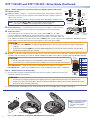
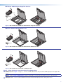
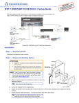
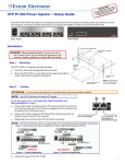
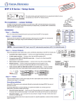
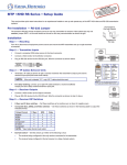
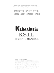
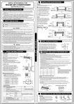
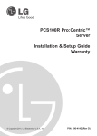
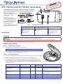
NT: ompletned
RTAfor the cio
O
ns, a
P
m
IM n.co
truct
the
g
ins
tro
w.ex tallation onnectin .
e
c
o ww
s
Go t uide, in s before er sourc
g
w
n
user cificatio o the po
spe roduct t
p
DTP T FB 332 and DTP T FB 232 • Setup Guide
HDMI IN
Rx Tx
SIG
LINK
DTP T FB 332
VGA IN
OUT
HDBT
DTP
Top Panel
Side Panel
Figure 1.
DTP T FB Unit features
Side (under adapter plate)
Installation
AUDIO IN
G
VGA
Rx
IR
Tx
+
HDMI
G
−
OVER DTP
RS-232
Tx Rx
POWER
12V
REMOTE
1.0A MAX RS-232
HDCP
AUTO
RESET
The transmitters switch
between one analog video and
one digital (HDMI) video input
and, paired with a compatible
receiver, can extend the
selected signal up to
330 feet (100 m) (DTP T FB 332) or
230 feet (70 m) (DTP T FB 232).
CONFIG
This guide provides instructions for an experienced installer to install either
the Extron DTP T FB 332 or the DTP T FB 232 switching transmitter into an
Ackermann GB3 (OBO-Betterman), MK Electric CableLink Plus Modular,
MK Electric CableLink Plus
Single Pan, ElectraPlan, or PUK
floor box and to make all
connections.
(Before installation in floor box)
(After installation in floor box)
Side (above adapter plate)
Top
A DC power input
B Remote RS-232
C TP function switch
D DTP output
E HDMI input
F VGA Input
G Audio input
H RS-232/IR Over TP output
I Configuration (USB)
J Reset button
KLEDs
Planning
CAUTION: Failure to check these items may result in personal injury or property damage.
ATTENTION : La non-vérification des éléments listés ci-dessous peut provoquer des blessures ou dommages matériels.
Check that the installation meets the building, electrical, and safety codes.
Mounting and Cabling
Step 1 — Preparing the floor box
a.
Install the floor box as directed by the manufacturer.
NOTE: Run all required cables and secure them with cable clamps.
b. Turn off or disconnect all equipment power sources.
Step 2 — Installing adapters
a.
1
Determine a position in the floor box to mount the DTP T FB unit (see the image at right).
2
b. Identify the applicable adapter plates for the floor box (see the table below).
c.
Install adapter plates to the same pair of mounting slots (see the table below for slot
recommendations) for the same position in the floor box. Slide the top flange into the
mounting slot and rotate the adapter plate down so the bottom flange rests against the
wall of the floor box.
Floor Box
Adapter Plates
Positions
Ackermann GB3
(OBO Betterman)
995241 (2)
995241 (2) and 995242 (1)
1 and 3
2
3rd from top
MK Electric CableLink Plus
Single Pan
995243 (2)
1 and 3
N/A
MK Electric CableLink Plus Modular
995244 (2)
1, 2, and 3
3rd from top
ElectraPlan
995300 (2)
1, 2, and 3
3rd from top
PUK
995300 (2)
1, 2, and 3
3rd from top
Highest
Mounting Slot
3
Typical Floorbox
Additional Notes
For position 2, use the provided screws to attach
the 995242 adapter plate to either 995241
adapter plate.
Do not use position 2. Use mounting screws to
secure the adapter plates to the floor box (see
figure 3 on page 3).
1
DTP T FB 332 and DTP T FB 232 • Setup Guide (Continued)
Ridges
Captive
Screw
Connector
Power (see figure 1 on page 1) — Connect the included 12 VDC power supply to either unit,
transmitter or receiver, as shown at right. Use the included tie-wrap to strap the cord to the
captive screw connector.
NOTE: If the TP switch (C) is in DTP, one power supply can power both units.
If the switch is in HDBT, each unit requires its own power supply.
B
Remote RS-232 port — For serial RS-232 control, connect a host device or control system to
the 3.5 mm, 3-pole captive screw connector. The wiring and protocol are shown at right.
C
TP function switch —
If the receiving device is in the Extron DTP series, set this switch to DTP. The TP output
consists of HDMI with embedded audio, analog audio, RS-232 and IR, and remote power. The
transmitter and receiver can be powered by one 12 VDC power supply connected to either unit.
3"
16 (5 mm) MAX
SECTION A–A
Power Supply A
Output Cord
A
G
Connect an IEC power cord between the power supply and a 100-240 VAC, 50-60 Hz source.
REMOTE
RS-232
A
Smooth
Rx Tx
Step 3 — Make side panel connections under the adapter plates and set the
TP function switch
3"
16 (5 mm) MAX
RS-232 Device • 9600 Baud
• 8 data bits
• No parity
• 1 stop bit
Tx Rx Gnd
For an HDBaseT-enabled receiver type, set this switch to HDBT position. The TP output consists of HDMI with embedded audio plus
RS-232 and IR. The transmitter and receiver each requires its own 12 VDC power supply.
ATTENTION:
• Position this switch BEFORE connecting the appropriate device to the TP connector. Failure to comply can damage the
endpoint.
• Positionnez le sélecteur AVANT de connecter l’appareil approprié au connecteur TP. Ne pas respecter cette procédure
pourrait endommager le point de connexion.
D
Out port— Connect the Out (RJ-45) port to the DTP In port on the receiver. Extron recommends that you terminate both cable ends in
accordance with the following, at a minimum: TIA/EIA T 568B and 24 AWG, solid conductor, shielded cable with 400 MHz bandwidth.
Pins:
12345678
ATTENTION:
• Do not connect this connector to a computer data or telecommunications network.
• Ne connectez pas ces port à des données informatiques ou à un réseau de télécommunications.
TIA/EIA T
568B
Pin Wire color
1 White-orange
2
3
White-green
Link LED indicator — Lights when a valid link between a DTP or HDBT input and output is established.
4
Blue
5
White-blue
Green
Step 4 — Mount the unit in the floor box
a.
Orange
Signal LED indicator — Lights when the device is transmitting a video signal or a test pattern.
6
Place the DTP T FB unit in the desired position in the floor box so that the side panel connectors face
towards the opening of the floor box.
TP Wires
7
White-brown
8
Brown
ATTENTION:
• Ensure there is enough space between the top panel connectors and the lid of the floor box so the lid fully closes.
• Assurez vous qu’il y ait assez d’espace entre les connecteurs du panneau supérieur et le couvercle du boîtier de sol afin
que celui-ci puisse se fermer entièrement.
b. Using the provided self-threading screws, secure the DTP T FB unit to the adapter plates (see figures 2 through 5).
Ackermann GB3 (OBO Betterman) floor box
DT
PT
FB
33
2
DT
PT
PO
12VWER
A MA RE
X RSMO
-23TE
2
- +
995242
2
995241
G
Rx
Tx
XT
P OU
T
Figure 2. DTP T FB Unit in an Ackermann GB3 (OBO Betterman) Floor Box
FB
33
2
NOTE: For position 2, install
adapter plate 995242 to
one of the other adapter
plates.
MK Electric CableLink Plus Single Pan floor box
DT
PT
FB
332
995243
995243
DT
PT
FB
332
PO
12VWER
A MA RE
X RSMO
-23TE
2
- +
G
Rx
Tx
DT
PT
FB
332
XT
PO
12VWER
A MA RE
X RSMO
-23TE
2
Figure 3. DTP T FB Unit in an MK Electric CableLink Plus Single Pan Floor Box
MK Electric CableLink Plus Modular floor box
TP
D
T
FB
2
33
D
TP
T
FB
33
2
995244
995244
PO
12VWER
A MA RE
X RSMO
-23TE
2
- +
G
Rx
XT
Tx
P OU
T
Figure 4. DTP T FB Unit in an MK Electric CableLink Plus Modular Floor Box
ElectraPlan or PUK floor box
DT
PT
FB
332
X
TP
T
FB
20
2
995300
995300
PO
12VWER
A MA RE
X RSMO
-23TE
2
- +
G
Rx
Tx
XT
P OU
T
Figure 5. DTP T FB Unit in an ElectraPlan (or PUK) Floor Box
Step 5 — Make side panel connections above the adapter plates
E
HDMI input port (see figure 1 on page 1) — Connect an HDMI cable between this port and the HDMI output port of the digital video
source.
NOTE: See the LockIt® Lacing Brackets on page 4 of this guide to securely fasten the HDMI connector to the transmitter.
F
VGA Input 1 port — Connect a VGA cable between this port and the VGA output port of the analog video source.
3
DTP T FB 332 and DTP T FB 232 • Setup Guide (Continued)
Step 6 — Make top panel connections
G
Audio input (see figure 1 on page 1) — Connect an unbalanced stereo audio source to this 3.5 mm mini stereo jack for an analog
audio input.
NOTE: Analog input audio is not embedded in the HDMI signal; it is transmitted separately and is present for any selected input.
Rx
Tx
Reset button — This button initiates two levels of reset. See the DTP T FB 332 and
DTP T FB 232 User Guide, available at www.extron.com, for details.
G
J
Tx Rx
Configuration port — Plug a PC or other controlling device into the switching transmitter via
this top panel mini-USB connector for remote configuration of the switching transmitter.
Rx Tx Gnd
IR
I
IR Device
OVER DTP
RS-232 and IR connector — To pass serial or infrared data or control signals on the Over DTP
RJ-45 output, connect the controlling device to the transmitter via the RS-232 and IR captive
screw connector. Connect the device to be controlled to the receiver.
RS-232
H
Tx Rx Gnd
RS-232 Device
Operation
After all connected devices are connected and powered on, the system is fully operational. The DTP T FB unit can be configured and
controlled using Extron Simple Instruction Set (SIS) commands (see the DTP T FB 332 and DTP T FB 232 User Guide available at
www.extron.com).
Indicators (K, see figure 1)
Power LED — Lights when power is applied.
HDMI
HDMI LED — Lights when the HDMI input signal is detected.
VGA
VGA LED — Lights when the VGA input signal is detected.
HDCP
HDCP LED — Lights when the HDMI input signal is encrypted.
AUTO
Auto LED — Lights when device is in auto switch mode. Auto switch is on by default.
When auto switch is on, the switcher automatically selects the input, HDMI or VGA, that has a valid signal present. When signals are
present on both inputs. the switcher selects VGA.
NOTE: Auto switch mode can be toggled off and on using the SIS commands. Issue the EnAUSW} SIS command,
where n = 0 (off) or 1 (on). The switcher responds with Auswn]. See the DTP T FB 332 and DTP T FB 232 User Guide,
available at www.extron.com, for details.
LockIt® Lacing Brackets
Use the included LockIt Lacing Brackets to securely fasten the HDMI cable as follows.
1. Plug the HDMI cable into the panel connection.
2. Loosen the HDMI connection mounting screw from the panel enough to allow the LockIt lacing
bracket to be placed over it. The screw does not have to be removed.
3. Place the LockIt lacing bracket on the screw and against the HDMI connector, then tighten the
screw to secure the bracket.
ATTENTION:
• Do not overtighten the HDMI connector mounting screw. The shield it fastens to is very
thin and can easily be stripped.
3
• Ne serrez pas trop la vis de montage du connecteur HDMI. Le blindage auquel elle est
attachée est très fin et peut facilement être dénudé.
4. Loosely place the included tie wrap around the HDMI connector and the LockIt lacing bracket as
shown.
5. While holding the connector securely against the lacing bracket, use pliers or similar tools to tighten the tie wrap, then remove any
excess length.
Extron Headquarters
+800.633.9876 Inside USA/Canada Only
Extron USA - West
Extron USA - East
+1.714.491.1500+1.919.850.1000
+1.714.491.1517 FAX
+1.919.850.1001 FAX
4
Extron Europe
+800.3987.6673
Inside Europe Only
+31.33.453.4040
+31.33.453.4050 FAX
Extron Asia
+65.6383.4400
+65.6383.4664 FAX
Extron Japan
+81.3.3511.7655
+81.3.3511.7656 FAX
Extron China
+86.21.3760.1568
+86.21.3760.1566 FAX
Extron Middle East
+971.4.299.1800
+971.4.299.1880 FAX
Extron Korea
+82.2.3444.1571
+82.2.3444.1575 FAX
Extron India
1800.3070.3777
(Inside India Only)
+91.80.3055.3777
+91.80.3055.3737 FAX
© 2014 Extron Electronics All rights reserved. All trademarks mentioned are the property of their respective owners. www.extron.com
68-2682-50 Rev. A
08 14