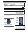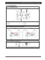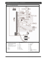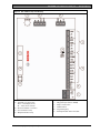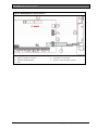
1
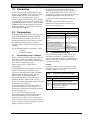
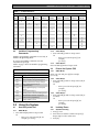
ICP-CC404
Quick Reference Guide
EN
ICP-CC404
Control Panel
ICP-CC404 | Quick Reference Guide | Copyright Notice
Copyright Notice
Notice of Liability
Unless otherwise indicated, this publication is the
copyright of Bosch Security Systems, Inc. (“Bosch”).
All rights are reserved.
While every precaution has been taken in the
preparation of this document, neither Bosch Security
Systems, Inc. nor any of its official representatives
shall have any liability to any person or entity with
respect to any liability, loss or damage caused or
alleged to be caused directly or indirectly by the
information contained in this book.
You may download a single copy of this publication.
By downloading the publication you agree that you
will: (i) only use the publication for your own
reference; (ii) not commercially exploit or charge any
person for the use of the publication; and (iii) not
modify the publication in any way without the prior
written permission of Bosch.
Except as specified above or where authorized by the
Copyright Act 1968 (Cth), no part of this publication
may be reproduced, transmitted, modified or stored,
in any form or by any means, without the prior
written permission of Bosch.
2
Bosch Security Systems, Inc. reserves the right to
make changes to features and specifications at any
time without prior notification in the interest of
ongoing product development and improvement.
Bosch Security Systems, Inc. | 10/08 | F01U089402-02
ICP-CC404 | Quick Reference Guide | Contents
Contents
Figures
1.0
2.0
2.1
2.2
2.3
3.0
3.1
3.1.1
3.1.2
3.1.3
3.2
3.2.1
3.2.2
3.2.3
3.3
3.3.1
3.3.2
3.4
3.5
3.6
3.7
3.8
3.9
3.9.1
3.9.2
3.9.3
3.10
3.11
3.12
3.13
3.14
3.15
3.16
3.17
3.18
3.19
3.20
3.21
3.22
3.23
3.24
4.0
5.0
6.0
7.0
Figure 1:
Figure 2:
Figure 3:
Figure 4:
Introduction ......................................................4
Programming ....................................................4
Programming Using a Codepad .......................4
Programming Option Bits .................................4
Installer’s Programming Commands................5
Using the System..............................................5
Arm the System (On).........................................5
AWAY Mode .....................................................5
STAY Mode 1 ....................................................5
STAY Mode 2 ....................................................5
Disarm the System (Off) ....................................5
AWAY Mode .....................................................5
STAY Mode 1 ....................................................5
STAY Mode 2 ....................................................5
Isolating Zones....................................................5
Standard Isolating ..............................................5
Code to Isolate ...................................................6
Set First Test Report ..........................................6
Event Memory Recall........................................6
Walk Test Mode.................................................6
Satellite Siren Service Mode .............................6
Telephone Monitor Mode (Toggle On/Off) ...6
Add/Delete User Code/RF Keyfob .................6
Add a User Code ...............................................6
Add an RF Keyfob.............................................6
Delete a User Code/RF Keyfob .......................6
Change Domestic Telephone Numbers ..........6
Turn Outputs On/Off........................................6
Setting Date and Time.......................................6
Day Alarm – Toggle On/Off ............................6
Program STAY Mode 2 Zones .........................7
Fault Analysis......................................................7
Modem Call (Alarm Link) ................................7
Reset Latching Outputs .....................................7
Set the Codepad ID/Buzzer Tone....................7
Test Report .........................................................7
Speaker Test........................................................7
Bell Test...............................................................7
Strobe Test (Toggle On/Off).............................7
Telco Arm Sequence (Call Forward On).........7
Telco Disarm Sequence (Call Forward Off)....7
Programming Parameters..............................8
Two-Channel and Four-Channel Keyfobs14
Wiring Diagrams............................................15
Country Codes................................................19
Bosch Security Systems, Inc. | 12/08 | F01U089402-02
Figure 5:
Figure 6:
Figure 7:
Figure 8:
RE012/E: 2-Channel Keyfob Transmitter14
RE013/E: 4-Channel Keyfob Transmitter14
Split EOL Wiring Diagram ......................15
Split EOL Wiring Diagrams Using N/O
Contacts......................................................15
Wiring Diagram for Keyswitch Zone......15
ICP-CC404 Wiring Diagram ...................16
ICP-CC404 Component Overlay............17
WE800/E Wireless On/Off Interface .....18
Tables
Table 1:
Table 2:
Table 3:
Table 4:
Table 5:
Table 6:
Quick Guide to Programming ...................4
Programming Option Bits Example..........4
Codepad Indicators.....................................5
Installer’s Programming Commands ........5
Telephone Monitor Mode Zone LEDs.....6
Fault Condition Indicators .........................7
3
ICP-CC404 | Quick Reference Guide | 1.0
Introduction
1.0 Introduction
Thank you for choosing the ICP-CC404 Control
Panel for your installation. This system is extremely
flexible, reliable, and easy to use. This quick
reference guide is supplied with the system to
provide enough basic information to wire, configure,
and program the system. Due to the system’s many
programmable features and options, get the complete
Installation Guide (P/N: F01U089401) that provides
detailed information on system options, functions,
and programming methods.
2.0 Programming
The programming options of the system are stored in
a non-volatile EPROM. This memory holds all
information during a total power loss. You can
change the information as many times as necessary.
The entire programming sequence consists of
entering a location number and changing the data as
required.
Use the following methods to program the system:
−
−
2.1
Codepad
Alarm Link Software
Programming Using a Codepad
Before you can program the system, the system must
be disarmed (with no active alarm). If there is an
active alarm or the system is armed, enter the Master
Code (default = 2580) and press [#].
Table 1 on page 4 shows a quick guide to
programming:
To enter Installer’s Programming Mode, enter the
installer code (default = 1234) and press [#].
Two beeps sound and both the STAY and AWAY
indicators flash simultaneously. The codepad
indicators show the data programmed in
Location 000 (the first location of the Primary
Telephone Number). Refer to Table 3 on page 5.
To move to another programming location, enter the
location number and press [#].
The codepad indicators show the data in the new
location (for example, enter [3 4 #] to move to
Location 034, the first location of the Subscriber ID
Number For Receiver 1).
To change the data programmed in the current
location, enter the new value (0 to 15) and press [*].
The codepad indicators show the new value. For
example, if you enter [1 4 *], both the Zone 4 and the
MAINS indicators light to show the new value).
To exit from Installer’s Programming Mode, enter
[9 6 0 #].
Two beeps sound and the STAY and AWAY
indicators turn off. The system is returned to the
disarmed state, ready for use.
Table 1: Quick Guide to Programming
Task
Keys to Press
Enter Installer’s Programming
Mode
Exit from Installer’s Programming
Mode
Move to the next location
Move to the previous location
Program data into the location
[1 2 3 4 #]
Move to another location
2.2
[9 6 0 #]
[#]
[*]
[Data][*]
(Data = 0 to 15)
[Location number][#]
Programming Option Bits
Some parameters provide up to four options. Use
option bits to program any combination of the
options in one location. To select a combination of
options, add the option numbers together. Program a
0 to disable all options.
Example
To program options 1 and 4 for Location 177, add
the numbers together and program the sum. In this
example, program 5 (1 + 4 = 5).
Table 2: Programming Option Bits Example
Option
1
2
4
8
Description
Dialer reporting functions allowed.
Remote arming by telephone allowed.
Answering machine bypass only when armed.
Use Bell 103 for FSK format
(disabled = CCITT V21).
To move to the next location, press [#].
The codepad indicators show the data in the next
location (for example, if you are positioned at
Location 034, press [#] to move to Location 035).
To move back one position, press [*] (for example, if
you are currently positioned at Location 35, pressing
[*] takes you back to Location 34).
4
Bosch Security Systems, Inc. | 12/08 | F01U089402-02
ICP-CC404 | Quick Reference Guide | 3.0
Using the System
Table 3: Codepad Indicators
Data
Value
Zone 1
Indicator
0
1
2
3
4
5
6
7
8
9
10
11
12
13
14
15
2.3
Zone 2
Indicator
Zone 3
Indicator
Zone 4
Indicator
Zone 5
Indicator
Zone 7
Indicator
Zone 8
Indicator
MAINS
Indicator
X
X
X
X
X
X
X
X
X
X
X
X
X
X
X
X
X
X
X
X
X
Installer’s Programming
Commands
Installer’s programming commands are used only in
Installer’s Programming Mode.
To execute an installer’s command, enter the
command and press [#].
Table 4 on page 5 shows the installer’s programming
commands.
Table 4: Installer’s Programming Commands
Command
959
960
961
962
Zone 6
Indicator
Description
Test programming key
Exit from Installer’s Programming Mode
Default system back to factory settings
Copy control panel memory to
programming key
Copy programming key to control panel
memory
Erase programming key
Default system for domestic dialing format
Enable/disable automatic stepping of
locations when programming
Display software version
3.1.2 STAY Mode 1
1. Press and hold [*] until two beeps sound.
Or
− Enter your code and press [*] (for
example,
[2 5 8 0 *]).
3.1.3 STAY Mode 2
Press and hold [0] until two beeps sound.
3.2
Disarm the System (Off)
3.2.1
AWAY Mode
Enter your code and press [#] (for example,
[2 5 8 0 #]).
3.0 Using the System
3.2.2 STAY Mode 1
1. Press and hold [*] until two beeps sound (only if
no alarm).
Or
− Enter your code and press [#] (for
example,
[2 5 8 0 #]).
3.2.3 STAY Mode 2
1. Press and hold [0] until two beeps sound (only if
no alarm).
Or
− Enter your code and press [#] (for
example,
[2 5 8 0 #]).
3.1
3.3
963
964
965
966
999
Arm the System (On)
3.1.1 AWAY Mode
1. Press and hold [#] until two beeps sound.
Or
− Enter your code and press [#] (for
example, [2 5 8 0 #]).
Bosch Security Systems, Inc. | 12/08 | F01U089402-02
Isolating Zones
3.3.1 Standard Isolating
1. Press [*] twice.
2. Enter the zone number to isolate and press [*].
Repeat Step 2 to select other zones.
3. Press [#].
5
ICP-CC404 | Quick Reference Guide | 3.0
Using the System
3.3.2 Code to Isolate
1. Press [*].
2. Enter your user code and press [*].
3. Enter the zone number to isolate and press [*].
Repeat Step 3 to select other zones.
4. Press [#] to exit.
3.4
1.
2.
Set First Test Report
Enter the Installer Code and press [1 #] (for
example, [1 2 3 4 1 #]).
Enter the number of days (0 to 15) to wait until
the first Test Report, and press [#].
3.5
Event Memory Recall
Enter the Installer Code and press [8 #] keys (for
example, [1 2 3 4 8 #]).
The last 40 events appear in reverse order (most
recent to least recent).
3.6
1.
2.
3.
Satellite Siren Service Mode
Enter the Installer Code and press [5 #] (for
example, [1 2 3 4 5 #]).
3.8
2.
3.
Telephone Monitor Mode (Toggle
On/Off)
Enter the Installer Code and press [6 #] (for
example, [1 2 3 4 6 #]).
To send a Test Report, press and hold [9] until
two beeps sound.
The codepad indicators show the dialing events
(refer to Table 5 on page 6).
Enter the Installer Code and press [6 #] to turn
Telephone Monitor Mode off.
You must exit from Telephone Monitor
Mode to resume normal operations.
3.9.1 Add a User Code
1. Enter the Master Code and press [1 #] (for
example, [2 5 8 0 1 #]).
2. Enter the user number (1 to 16) to add, and press
[#].
3. Enter the new code and press [#].
3.9.2 Add an RF Keyfob
1. Enter the Master Code and press [1 #] (for
example, [2 5 8 0 1 #]).
2. Enter the user number (9 to 16) to add, and press
[#].
4. Press the RF keyfob until hearing two beeps. The
RF keyfob is added. Refer to the ICP-CC404
Installation Guide for more details.
You can only program User Codes 9 to
16 as RF users.
3.9.3 Delete a User Code/RF Keyfob
1. Enter the Master Code and press [1 #] (for
example, [2 5 8 0 1 #]).
2. Enter the user number (1 to 16) to delete, and
press [#].
3. Press [*] to delete the user code.
3.10
1.
2.
3.
4.
1.
2.
3.
Zone LED
Dialing Event
1
2
3
4
5
None
Telephone line seized
Dialing telephone number
Handshake received
Data being sent
Kiss-off received
Released telephone line
2.
3.
Turn Outputs On/Off
Enter the Master Code and press [5 #] (for
example, [2 5 8 0 5 #]).
Enter the output number (1 to 3).
Press [#] to toggle the output on, or [*] to toggle
the output off.
Press [#] to exit.
3.12
1.
Change Domestic Telephone
Numbers
Enter the Installer Code or Master Code and
press [2 #] (for example, [1 2 3 4 2 #]).
Enter the digits of the telephone number.
If there is more than one telephone number,
enter [* 4] (which inserts a break between phone
numbers), then repeat Step 2.
Press [#] to exit.
3.11
4.
Table 5: Telephone Monitor Mode Zone LEDs
6
Add/Delete User Code/RF Keyfob
Walk Test Mode
Enter the Installer Code or Master Code and
press [7 #] (for example, [1 2 3 4 7 #]).
Test each zone.
Press [#] to exit.
3.7
1.
3.9
Setting Date and Time
Enter the Master Code and press [6 #] (for
example, [2 5 8 0 6 #]).
Enter the day (DD), month (MM), year (YY),
hour (HH) and minute (MM).
Press [#] to exit.
3.13
Day Alarm – Toggle On/Off
Press and hold [4] until two beeps sound.
Day alarm toggles on or off.
Bosch Security Systems, Inc. | 12/08 | F01U089402-02
ICP-CC404 | Quick Reference Guide | 3.0
3.14
1.
2.
3.
4.
Program STAY Mode 2 Zones
Enter the Installer Code or Master Code and
press [4 #] (for example, [1 2 3 4 4 #]).
Enter the zone number to automatically isolate,
and press [*].
Repeat Step 2 to program other zones.
Press [#] to exit.
3.15
1.
2.
3.
Fault Analysis
Press and hold [5] until two beeps sound.
The zone indicators show the fault condition.
Refer to Table 6 on page 7.
Press [#] to exit.
3.19
3.20
3.21
3.16
3.22
1.
Press and hold [6] until two beeps sound.
3.17
Reset Latching Outputs
1.
2.
3.
4.
2.
3.
4.
Telco Arm Sequence (Call Forward
On)
Enter the Installer Code or Master Code and
press [3 #] (for example, [1 2 3 4 3 #]).
Enter [1 #].
Enter the Call Forward On sequence.
Press [#] to exit.
3.24
1.
Strobe Test (Toggle On/Off)
To turn the strobe on, press and hold [3] until
three beeps sound.
To turn the strobe off, press and hold [3] until
two beeps sound.
FAULT Condition
Modem Call (Alarm Link)
Bell Test
Press and hold [2] until two beeps sound.
The piezo siren sounds for 2 sec.
3.23
Battery low
Date/time reset
Sensor watch fail
Horn speaker fail
Telephone line fail
EEPROM fail
AUX Power Supply fail
Communication fail
Speaker Test
Press and hold [1] until two beeps sound.
The speaker sounds for 2 sec.
2.
1
2
3
4
5
6
7
8
Test Report
Press and hold [9] until two beeps sound.
Table 6: Fault Condition Indicators
Zone LED
Using the System
Telco Disarm Sequence (Call
Forward Off)
Enter the Installer Code or Master Code and
press [3 #] (for example, [1 2 3 4 3 #]).
Enter [2 #].
Enter the Call Forward Off sequence.
Press [#] to exit.
Press and hold [7] until two beeps sound.
3.18
1.
2.
Set the Codepad ID/Buzzer Tone
Press and hold [8] until the desired buzzer tone
sounds.
Press [#] to exit.
Bosch Security Systems, Inc. | 12/08 | F01U089402-02
7
ICP-CC404 | Quick Reference Guide | 4.0
Programming Parameters
4.0 Programming Parameters
Location
Function
000 to 015
Phone Number 1 - Receiver 1
016 to 031
Phone Number 2 - Receiver 1
032
Handshake Tone – Receiver 1
033
Transmission Format –
Receiver 1
034 to 039
Subscriber ID Number – Receiver 1
040 to 055
Phone Number 1 - Receiver 2
056 to 071
Phone Number 2 - Receiver 2
072
Handshake Tone – Receiver 2
Options/Notes
Default
0 = 10 and telephone termination = 0
anywhere else 0 = 0
0000000000000000
0 = 10 and telephone termination = 0
anywhere else 0 = 0
1 HI-LO handshake (contact ID)
2 1400 Hz (Ademco TX @ 1900 Hz)
3 2300 Hz (Sescoa TX @ 1800 Hz)
1 Contact ID
2 4 + 2 express
3 FSK 300 baud
0000000000000000
4 No handshake
5 Pager
1
4 Domestic
5 Basic pager
1
Right justified
000000
0 = 10 and telephone termination = 0
anywhere else 0 = 0
0000000000000000
0 = 10 and telephone termination = 0
anywhere else 0 = 0
1 HI-LO handshake (contact ID)
2 1400 Hz (Ademco TX @ 1900 Hz)
3 2300 Hz (Sescoa TX @ 1800 Hz)
1 Contact ID
2 4 + 2 express
3 FSK 300 baud
0000000000000000
4 No handshake
5 Pager
1
4 Domestic
1
073
5 Basic pager
Transmission Format –
Receiver 2
Right justified
000000
074 to 079
Subscriber ID Number – Receiver 2
4 International DTMF
1 Australian DTMF
1
080
5 Reversed decadic
2 Australian decadic
Dialing Format
3 Alternate DTMF and Australian decadic 6 Alternate DTMF and reversed decadic
000000000000000
113 to 142
000000000000000
Telco Arming Sequence (Call Forward On)
0000000000000000
143 to 158
Telco Disarm Sequence (Call Forward Off)
0 = 10 and telephone termination = 0
0000000000000000
159 to 174
anywhere else 0 = 0
Call Back Telephone Number
0
Control panel does not answer
8
175
1 to 13 Number of rings until control panel answers
Ring Count
14
Answering machine bypass 2
15
Answering machine bypass 1
1 Display FAULT indicator when telephone line fails
0
176
2 Sound alarm when system arms
Telephone Line Fail Options
4 Sound alarm when system disarms
Options 2 and 4 must be used in conjunction with Option 1
(for example, program 1, 3, 5, or 7).
1 Dialer reporting functions allowed
9
177
2 Remote arming by telephone allowed
Dialer Options 1
4 Answering machine bypass only when armed
8 Bell 103 used for FSK format (Disabled = CCITT V21)
1 Open/Close Reports only if previous alarm
0
178
2 Open/Close Reports for STAY Mode 1 and STAY Mode 2
Dialer Options 2
4 Delay siren until transmission complete
8 Extend handshake wait time from 30 sec to 60 sec
8
Bosch Security Systems, Inc. | 12/08 | F01U089402-02
ICP-CC404 | Quick Reference Guide | 4.0
Location
Function
179
Dialer Options 3
180
Alarm Link Options
Options/Notes
1
2
4
8
1
2
4
8
267 to 322
Zone
Defaults
0
1
2
3
Default
Set DTMF dialing pulses to 1 digit/sec
Reserved
Change decadic dialing to 60/40
Reserved
Upload/download allowed
Call back phone number required for upload/download
Exit upload/download connection on alarm
Reserved
181 to 184
Installer Code
* The fifth location in each user code is the
185 to 264
authority level:
User Codes
0 Arm/disarm
1 Arm only
2 Arm/disarm and open/close reports
3 Arm only and close reports
4 Arm/disarm and code required to isolate
6 Arm/disarm and open/close reports and code
required to isolate
8 Master code and arm/disarm
10 Master code and arm/disarm and open/close
reports
12 Master code and arm/disarm and code
required to isolate
14 Master code and arm/disarm and code
required to isolate and open/close reports
1 Zone 1
265
2 Zone 2
Day Alarm Zones
266
EOL Resistor Value
Programming Parameters
No EOL
1K
1K5
2K2
4
5
6
7
3K3
3K9
4K7
5K6
0
3
1234
User #01 (185 to 189)
User #02 (190 to 194)
User #03 (195 to 199)
User #04 (200 to 204)
User #05 (205 to 209)
User #06 (210 to 214)
User #07 (215 to 219)
User #08 (220 to 224)
RF User #09 (225 to 229)
RF User #10 (230 to 234)
RF User #11 (235 to 239)
RF User #12 (240 to 244)
RF User #13 (245 to 249)
RF User #14 (250 to 254)
RF User #15 (255 to 259)
RF User #16 (260 to 264)
4 Zone 3
8 Zone 4
8
9
10
11
6K8
10K
12K
22K
12
13
14
15
2 5 8
15 15
15 15
15 15
15 15
15 15
15 15
15 15
15 15
15 15
15 15
15 15
15 15
15 15
15 15
15 15
15
15
15
15
15
15
0
15
15
15
15
15
15
15
15
0 10*
15 2*
15 2*
15 2*
15 2*
15 2*
15 2*
15 3*
15 2*
15 2*
15 2*
15 2*
15 2*
15 2*
15 2*
15 2*
0
Reserved
Reserved
Reserved
Split EOL (3K3/6K8)
Zone #01 (Default = Delay 1) (267 to 273)
Zone #02 (Default = Handover) (274 to 280)
Zone #03 (Default = Handover) (281 to 287)
Zone #04 (Default = Instant) (288 to 294)
Zone #05 (Default = Fixed 24-hr burglary) (295 to 301)
Zone #06 (Default = Fixed 24-hr burglary) (302 to 308)
Zone #07 (Default = Fixed 24-hr fire) (309 to 315)
Zone #08 (Default = Fixed Tamper) (316 to 322)
2
1
1
0
12
12
13
9
The first location (from the left) of the zone definition is the Zone Type. The options are:
12
8 24-hour hold-up
4 Reserved
0 Instant
13
9 24-hour tamper
5 Reserved
1 Handover
14
10 Reserved
6 24-hour medical
2 Delay 1
15
11 Keyswitch
7 24-hour panic
3 Delay 2
0
0
0
0
0
0
0
0
0
0
0
0
0
0
0
0
1
1
1
1
1
1
1
1
14
14
14
14
12
12
12
12
15
1
1
1
1
1
1
1
1
1
1
1
1
1
1
1
1
24-hour burglary
24-hour fire
Chime
Not used
The second location of the zone definition is the Zone Pulse Count. Use the pulse count to program the
number of pulses (0 to 15) that must register within the pulse count time to activate an alarm.
The third location (from the left) of the zone definition is the Zone Pulse Count Time. The options are:
20 ms Loop Response Time:
150 ms Loop Response Time:
12 60 sec
8 20 sec
4 4 sec
0 0.5 sec
13 90 sec
9 30 sec
5 5 sec
1 1 sec
14 120 sec
10 40 sec
6 10 sec
2 2 sec
15 200 sec
11 50 sec
7 15 sec
3 3 sec
The fourth location of the zone definition is the Zone Options 1 parameter. The options are:
1 Lockout siren/dialer
4 Silent alarm
2 Delay Alarm Report
8 Sensor watch
Bosch Security Systems, Inc. | 12/08 | F01U089402-02
9
ICP-CC404 | Quick Reference Guide | 4.0
Location
Function
267 to 322
Zone
Defaults
(continued)
Programming Parameters
Options/Notes
Default
The fifth location of the zone definition is the Zone Options 2 parameter. The options are:
1 Isolated in STAY Mode 1
4 Forced arming allowed
2 Zone isolation allowed
8 Zone Restore Report allowed
The sixth location of the zone definition is the Report Code. The options are:
0 Do not send Zone Alarm Reports
1 Send Zone Alarm Reports
The seventh location of the zone definition is the Zone Dialer Options parameter. The options are:
4 Report to both Receiver 1 and Receiver 2
0 No Zone Reports allowed
8 Report to Receiver 2 only if Receiver 1
1 Report to Receiver 1
fails
2 Report to Receiver 2
The keyswitch zone options replace Zone Options 1 for zones programmed to operate as keyswitch
zones (Zone Type = 11). The options are:
8 Momentary arm and disarm in AWAY
0 Latching arm and disarm in AWAY Mode
Mode
1 Latching arm in AWAY Mode
9 Momentary arm In AWAY Mode
2 Latching disarm from AWAY Mode or
10 Momentary disarm from AWAY Mode or
STAY Mode
STAY Mode
4 Latching arm and disarm in STAY Mode
12 Momentary arm and disarm in STAY Mode
5 Latching arm in STAY Mode
13 Momentary arm in STAY Mode
6 Latching disarm from STAY Mode
14 Momentary disarm from STAY Mode
1 to 15 Number of times siren operates until lockout
3
323
Swinger Shutdown Count for Siren
1 to 15 Number of times dialer operates until lockout
6
324
Swinger Shutdown Count for Dialer
9
325 Zone Bypass Report
8
326 Zone Bypass Restore Report
2
3
327 Zone Trouble Report
328 Zone Trouble Restore Report
329 Sensor Watch Report
330 Sensor Watch Restore Report
331 Zone Alarm Restore Code
332
Zone Status Reporting Options
333 Open Report
334 Close Report
335
Open/Close Reporting Options
4
5
14
0
1
2
4
8
No Zone Status Reports allowed
Report to Receiver 1
Report to Receiver 2
Report to both Receiver 1 and Receiver 2
Report to Receiver 2 only if Receiver 1 fails
1
11
12
0
1
2
4
8
No Open/Close Reports allowed
Report to Receiver 1
Report to Receiver 2
Report to both Receiver 1 and Receiver 2
Report to Receiver 2 only if Receiver 1 fails
1
6
336 Codepad Duress Report
337 to 338
Codepad Panic Report
339 to 340
Codepad Fire Report
341 to 342
Codepad Medical Report
343
Open/Close Reporting Options
0
1
2
4
8
7
15
Location 339: tens digit
Location 340: units digit
7
14
Location 341: tens digit
Location 342: units digit
7
13
No Codepad Alarm Reports allowed
Report to Receiver 1
Report to Receiver 2
Report to both Receiver 1 and Receiver 2
Report to Receiver 2 only if Receiver 1 fails
344 to 345
System Status – AUX Power Supply Fail Report
10
Location 337: tens digit
Location 338: units digit
1
Location 344: tens digit
Location 345: units digit
10
3
Bosch Security Systems, Inc. | 12/08 | F01U089402-02
ICP-CC404 | Quick Reference Guide | 4.0
Location
Function
346 to 347
System Status – AUX Power Supply Fail Restore
Report
348 to 349
System Status – AC Fail Report
350 to 351
System Status – AC Fail Restore Report
352 to 353
System Status – Low Battery Report
354 to 355
System Status – Low Battery Restore Report
356 to 358
System Status – Access Denied (Code Retry)
Options/Notes
Programming Parameters
Default
Location 346: tens digit
Location 347: units digit
10
8
Location 348: tens digit
Location 349: units digit
10
2
Location 350: tens digit
Location 351: units digit
10
7
Location 352: tens digit
Location 353: units digit
10
1
Location 354: tens digit
Location 355: units digit
10
6
Location 356: Code retry limit (0 = unlimited)
6
Location 357: tens digit
7
Location 358: units digit
12
0 No System Status Reports allowed
1
359
System Status Reporting Options 1 Report to Receiver 1
2 Report to Receiver 2
4 Report to both Receiver 1 and Receiver 2
8 Report to Receiver 2 only if Receiver 1 fails
Location 360: Hour of day (tens digit)
0
360 to 366
Location 361: Hour of day (units digit)
0
Test Report Time (Automatic)
Location 362: Minute of day (tens digit)
0
Location 363: Minute of day (units digit)
0
Location 364: Test Report (tens digit)
7
Location 365: Test Report (units digit)
1
Location 366: Repeat interval in days
0
0 No Test Reports allowed
1
367
1 Report to Receiver 1
Test Reporting Dialer Options
2 Report to Receiver 2
4 Report to both Receiver 1 and Receiver 2
8 Report to Receiver 2 only if Receiver 1 fails
1 14 0 0 0 0
Output 1 (Default = Horn speaker) (368 to 373)
368 to 397
2 7 10 2 1 5
Output 2 (Default = Fire alarm with verification) (374 to 379)
Outputs
2 0 6 40 8
Strobe Output (Default = Strobe – reset after 8 hr) (380 to 385)
1 15 1 0 0 0
Relay Output (Default = Sirens running) (386 to 391)
0 13 2 1 0 1
Codepad Buzzer (Default = Entry/exit plus day alarm) (392 to 397)
The first two locations (from the left) of the output definition provide the Event Code. The options are:
0 0
EDMSAT – satellite siren (Output 1
1 2
Kiss-off received
only)
0 1
System armed
1 3
AUX Power Supply fail
0 2
System disarmed
1 4
AC fail
0 3
Armed in STAY Mode
1 5
Low battery
0 4
Armed in AWAY Mode
1 6
Horn speaker fail
0 5
Pre-arming alert
1 7
Sensor watch alarm
0 6
Exit Warning (all zones sealed) and
1 8
Codepad medical alarm
entry warning
0 7
Exit Warning
1 9
Codepad fire alarm
0 8
Exit Warning finished
1 10 Codepad panic alarm
0 9
Kiss-off after end of Exit Time
1 11 Codepad duress alarm
0 10 Reserved
1 12 Access denied (code retries)
0 11 Entry warning
1 13 Reserved
0 12 Entry warning and day alarm resetting
1 14 Horn speaker (Output 1 only)
0 13 Exit Warning and entry warning and
1 15 Sirens running
day alarm resetting
0 14 Day alarm resetting
2 0
Strobe
0 15 Day alarm latching
2 1
Silent alarm
1 0
Day alarm enabled
2 2
Alarm in STAY Mode
1 1
Telephone line fail
2 3
Alarm in AWAY Mode
Bosch Security Systems, Inc. | 12/08 | F01U089402-02
11
ICP-CC404 | Quick Reference Guide | 4.0
Location
Function
368 to 397
Outputs
(continued)
Programming Parameters
Options/Notes
2
2
2
2
2
2
2
2
2
2
4
5
6
7
8
9
10
11
12
13
2 14
2 15
3
3
3
3
3
3
3
3
3
3
3
3
3
4
4
4
4
4
0
1
2
3
4
5
6
7
8
9
10
11
12
0
1
2
3
4
System fault
Fire alarm (resetting)
Fire alarm (latching)
Fire alarm (verification)
Remote Control 1
Remote Control 2
Remote Control 3
Radio Control Output 1
Radio Control Output 2
Radio Control Output 1 – not in
AWAY Mode
Radio Control Output 2 – not in
AWAY Mode
Communications fail after three
attempts
Communications fail
Dialer disabled
Dialer active (on-line)
Ring detect
Reserved
Mimic zone 1
Mimic zone 2
Mimic zone 3
Mimic zone 4
Mimic zone 5
Mimic zone 6
Mimic zone 7
Mimic zone 8
Reserved
Reserved
Reserved
Reserved
Reserved
4
4
4
4
4
4
4
4
4
4
5
6
7
8
9
10
11
12
13
14
Chime
Zone not sealed
Zone not sealed after Exit Time
Reserved
AC MAINS cycle (60 Hz or 50 Hz)
Reserved
Reserved
Reserved
Reserved
Reserved
4 15
Reserved
5 0
Reserved
5
5
5
5
5
5
5
5
5
5
5
5
5
5
5
6
6
Reserved
Reserved
Reserved
Reserved
Reserved
Reserved
Reserved
Reserved
Reserved
Reserved
Reserved
Reserved
Reserved
Reserved
Reserved
Reserved
Reserved
1
2
3
4
5
6
7
8
9
10
11
12
13
14
15
0
1
Default
The third location of the output definition is the output polarity. The options are:
8 Normally low, going open
0 Disabled
9 Normally low, pulsing open
1 Normally open, going low
10 Normally low, one shot open
2 Normally open, pulsing low
11 Normally low, one shot open (reactivate)
3 Normally open, one shot low
12 Normally low, one shot open (can reset)
4 Normally open, one shot low (reactivate)
13 Normally low, one shot open (alarm)
5 Normally open, one shot low (can reset)
14 Normally low, latching open
6 Normally open, one shot low (alarm)
7 Normally open, latching low
The fourth location of the output definition is the time base. The options are:
1 200 ms
3 1 min
2 1 sec
4 1 hr
The fifth and sixth locations of the output definition provide the time base multiplier. Enter a value between
01 and 99.
One Shot Mode
When you program the output polarity as one shot, the time base is multiplied by the time base multiplier.
For example, if the time base = 2 and the multiplier = 05, the output operates for 5 sec.
Pulsing Mode
When you program the output polarity as pulsing, the time base becomes the ON time and the multiplier
becomes the OFF time. The OFF time is the time base, which is multiplied by the multiplier. For example,
if you want the output to pulse 1 sec ON and 5 sec OFF, you would program time base as 2 and the
multiplier as 5.
12
Bosch Security Systems, Inc. | 12/08 | F01U089402-02
ICP-CC404 | Quick Reference Guide | 4.0
Location
Function
398 to 399
Entry Time 1
400 to 401
Entry Time 2
402 to 403
Exit Time (AWAY/STAY Modes)
404 to 405
Entry Guard Time for STAY Mode
406 to 407
Delay Alarm Report Time
408 to 409
Sensor Watch Time
410
Codepad Lockout Time
411
Siren Run Time
412
Siren Sound Rate
413
Auto Arming Pre-Alert Time
414 to 417
Auto Arming Time
Options/Notes
418 to 421
Auto Disarming Time
422
Kiss-Off Wait Time
423
Reserved
424
System Options 1
425
System Options 2
426
System Options 3
427
System Options 4
428
Consumer Options 1
429
Consumer Options 2
430
Consumer Options 3
Programming Parameters
Default
Location 398: increments of 1 sec (0 to 15 sec)
Location 399: increments of 16 sec (0 to 240 sec)
4
1
Location 400: increments of 1 sec (0 to 15 sec)
Location 401: increments of 16 sec (0 to 240 sec)
8
2
Location 402: increments of 1 sec (0 to 15 sec)
Location 403: increments of 16 sec (0 to 240 sec)
12
3
Location 404: increments of 1 sec (0 to 15 sec)
Location 405: increments of 16 sec (0 to 240 sec)
0
0
Location 406: increments of 1 sec (0 to 15 sec)
Location 407: increments of 16 sec (0 to 240 sec)
0
0
Location 408: increments of days (tens digit
Location 409: increments of days (units digit)
0
0
0
No lockout
1 to 15 Increments of 10 sec (10 sec to 150 sec)
0
0
No siren time
1 to 15 Increments of 1 min (1 min to 15 min)
5
0 (slowest frequency) to 15 (fastest frequency)
7
0
No pre-alert time
1 to 15 Increments of 5 min (5 min to 75 min)
1
Location 414: Hour of day (tens digit)
Location 415: Hour of day (units digit)
Location 416: Minute of day (tens digit)
Location 417: Minute of day (units digit)
Location 418: Hour of day (tens digit)
Location 419: Hour of day (units digit)
Location 420: Minute of day (tens digit)
Location 421: Minute of day (units digit)
0 to 15 Increments of 500 ms (500 ms to 8 sec)
0
0
0
0
0
0
0
0
3
0
1
2
4
8
1
2
4
8
1
2
4
8
1
2
4
8
1
2
4
8
1
2
4
8
1
2
4
8
Bosch smart lockout allowed
Horn speaker monitor
Strobe indication for radio arm/disarm
Horn speaker beeps for radio arm/disarm
Codepad panic to be silent
Codepad fire to be silent
Codepad medical to be silent
Access denied (code retries) to be silent
AC fail after 1 hr (disabled = after 2 min)
Ignore AC fail
Pulse count handover allowed
Handover delay to be sequential
Control panel to power up disarmed (if power reset)
Arm/disarm tracking on power up
Internal crystal to keep time
Night arm station or RE005 installed
Test reports only when armed
Test report after siren reset
Auto arm in STAY Mode 1
STAY indicator to display day alarm status
Codepad display extinguish after 60 sec
Single button arming allowed (AWAY/STAY Modes 1 and 2)
Single button disarming allowed (STAY Modes 1 and 2)
Alarm memory reset on disarm
Codepad fault beeps allowed
Use digit 3 for codepad duress alarm (instead of digit 9)
Alarms activate sirens and strobe outputs in STAY Modes 1 and 2
Reserved
Bosch Security Systems, Inc. | 12/08 | F01U089402-02
1
0
8
0
0
2
5
13
ICP-CC404 | Quick Reference Guide | 5.0
Location
Function
431
Radio Input Options
Two-Channel and Four-Channel Keyfobs
Options/Notes
1
2
3
4
Radio receiver (WE800)
Latching keyswitch input
Momentary keyswitch input
Reserved
748 to 749
Reserved
750 to 751
Country Codes
Refer to page 19
900
Default Options
901 to 904
System Time
Default
0
Location 750: Country Code (tens digit)
Location 751: Country Code (units digit)
0 Defaulting system allowed
15 Defaulting system disabled
0
Location 901: Hour of day (tens digit)
Location 902: Hour of day (units digit)
Location 903: Minute of day (tens digit)
Location 904: Minute of day (units digit)
Location 905: Day of the month (tens digit)
Location 906: Day of the month (units digit)
Location 907: Month of the year (tens digit)
Location 908: Month of the year (units digit)
Location 909: Current year (tens digit)
Location 910: Current year (units digit)
905 to 910
System Date
5.0 Two-Channel and
Four-Channel Keyfobs
0 2
0
0
0
0
0
1
0
1
0
1
Figure 2: RE013/E: 4-Channel Keyfob
Transmitter
1
Figure 1: RE012/E: 2-Channel Keyfob
Transmitter
3
1
2
2
3
1 – Button 1: Arm or disarm in AWAY Mode
2 – Button 2: Arm or disarm STAY Mode
3 – Buttons 1 and 2: Press both buttons at same
time to activate Panic alarm..
14
4
1 – Button 1: Arm or disarm in AWAY Mode
2 – Button 2: Arm or disarm in STAY Mode
3 – Buttons 1 and 2: Press both buttons at same
time to activate Panic alarm.
4 – Buttons 3 and 4: Your security company can
program these buttons for optional operation,
such as operating a garage door.
Bosch Security Systems, Inc. | 12/08 | F01U089402-02
ICP-CC404 | Quick Reference Guide | 6.0
Wiring Diagrams
6.0 Wiring Diagrams
Figure 3: Split EOL Wiring Diagram
1
8
2
4
7
3
5
6
5 – Zone 7
6 – Zone 8
7 – Zone 4
8 – Zone 5
1 – Zone 1
2 – Zone 2
3 – Zone 6
4 – Zone 3
Figure 4: Split EOL Wiring Diagrams Using N/O Contacts
Figure 5: Wiring Diagram for Keyswitch Zone
2
1
1 – Zone
Bosch Security Systems, Inc. | 12/08 | F01U089402-02
2 – Keyswitch (momentary/toggle)
15
ICP-CC404 | Quick Reference Guide | 6.0
Wiring Diagrams
Figure 6: ICP-CC404 Wiring Diagram
1 – 605 plug
2 – 6 (Red) Telecom line (street)
5 (Yellow) Internal phone line
3 and 4 Not used
2 (Black) Telecom line (street)
1 (Green) Internal phone line
3 – Zone 1
4 – Zone 5
5 – Zone 2
6 – Zone 6
16
7 – Power to external equipment:
12 V @ 400 mA
8 – PIR
9 – Zone 8
10 – Zone 4
11 – Zone 7
12 – Zone 3
13 – Piezo siren
14 – Smoke detector
15 – Strobe
16 – Horn speaker
17 – Codepad
18 – Yellow
19 – Green
20 – Red
21 – Black
22 – Battery
23 – 18 VAC 1.3 A plug pack
(TF008)
24 – Link between +12 V and Comm
Bosch Security Systems, Inc. | 12/08 | F01U089402-02
ICP-CC404 | Quick Reference Guide | 6.0
Wiring Diagrams
Figure 7: ICP-CC404 Component Overlay
1 – Socket for telecom lead connect
2 – Termination for phone line
OUT – internal phone line
IN – Telecom line (street)
3 – Receiver interface connection
4 – Zone termination strip
5 – Output termination strip
Bosch Security Systems, Inc. | 12/08 | F01U089402-02
6–
7–
8–
9–
10 –
11 –
Battery input
Plug pack input (Bosch TF008)
Relay contact select
Default switch
Programming key
Auxiliary Module: direct link cable
17
ICP-CC404 | Quick Reference Guide |
Figure 8: WE800/E Wireless On/Off Interface
1–
2–
3–
4–
18
Direct link cable
Receiver interface connection
Wireless On/Off Interface
Red
5 – Black
6 – Termination for phone line
7 – Socket for telecom lead connection
Bosch Security Systems, Inc. | 12/08 | F01U089402-02
ICP-CC404 | Quick Reference Guide | 7.0
Country Codes
7.0 Country Codes
The PSTN provides a programmable line interface to meet international telephone line requirements. This
program meets various country PTT standards.
Country
Code
Country
Code
Country
Code
Country
Code
Country
Code
Argentina
01
Poland
41
Liechtenstein
63
Gabon
65
Papua New
Guinea
65
Gambia
65
Paraguay
65
Ghana
65
Rwanda
65
65
St. Lucia
65
Samoa
Eastern
San Marino
65
Australia
02
Portugal
42
Austria
03
Romania
43
Afghanistan
65
Belgium
04
Russian
Federation
44
Albania
65
Brazil
05
45
Andorra
65
Grenada
65
Bulgaria
06
Saudi
Arabia
Serbia and
Montenegro
46
Angola
65
Guatemala
65
Canada
07
Singapore
47
Antigua and
Barbuda
65
Guinea
65
Sao Tome
and Principe
China
08
Slovakia
48
Azerbaijan
65
Guyana
65
Saint Vincent
65
Colombia
09
Slovenia
49
Bahamas
65
Haiti
65
Senegal
65
Croatia
10
South Africa
50
Bangladesh
65
Vatican
65
Seychelles
65
Cyprus
11
Spain
51
Barbados
65
Honduras
65
Sierra Leone
65
Czech
Republic
12
Sweden
52
Belize
65
Iran
65
Solomon Is
65
Denmark
13
Switzerland
53
Benin
65
Iraq
65
Somali
65
Egypt
14
Taiwan,
China
54
Bhutan
65
Ivory Coast
65
Sri Lanka
65
Bolivia
Estonia
15
Thailand
55
Finland
16
Turkey
56
France
17
United
Kingdom
57
Germany
18
United
States
Greece
19
Hong Kong,
PRC
20
Hungary
21
India
65
65
65
Jamaica
65
Sudan
65
65
Kenya
65
Suriname
65
Botswana
65
Kiribati
65
Swaziland
65
58
Brunei
65
Kuwait
65
Tajikistan
65
Venezuela
59
Burkina-faso
65
Laos
65
Tanzania
65
Vietnam
60
Burma
65
Lesotho
65
Togo
65
Burundi
65
Liberia
65
Tuvalu
65
22
Armenia
62
Cambodia
65
Libya
65
Uganda
65
Indonesia
23
Belarus
62
Cameroon
65
Madagascar
65
65
Ireland
24
Georgia
62
Cape Verde
65
Malawi
65
United Arab
Emirates
Uruguay
65
Italy
25
Jordan
62
Central African
Republic
65
Maldives
65
Uzbekistan
65
Vanuatu
65
Japan
26
Kazakhstan
62
Chad
65
Mali
65
Korea, South
27
Kyrgyzstan
62
Chile
65
Marshall
Islands
65
Latvia
28
Moldova
62
Comoros
65
Mauritania
65
Lithuania
29
Oman
62
Congo
65
Mauritius
65
65
Luxembourg
30
Pakistan
62
Costa Rica
65
Micronesia
Macedonia
31
Qatar
62
Cuba
65
Monaco
65
Malaysia
32
Syria
62
Djibouti
65
Mongolia
65
Malta
33
Ukraine
62
Dominica Rep.
65
Mozambique
65
East Timor
65
Namibia
65
Algeria
63
Ecuador
65
Nauru
65
Mexico
34
Netherlands
35
Bosch Security Systems, Inc. | 12/08 | F01U089402-02
19
ICP-CC404 | Quick Reference Guide | 7.0
Country Codes
Country
Code
Country
Code
Country
Code
Country
Code
New Zealand
36
Bahrain
63
El Salvador
65
Nepal
65
Nigeria
37
French
Polynesia
63
Equatorial Gui
nea
65
Nicaragua
65
Norway
38
Iceland
63
Eritrea
65
Niger
65
Peru
39
Israel
63
Ethiopia
65
Palau
65
Philippines
40
Lebanon
63
Fiji
65
Panama
65
20
Country
Code
Bosch Security Systems, Inc. | 12/08 | F01U089402-02
ICP-CC404 | Quick Reference Guide | Notes
Notes
Bosch Security Systems, Inc. | 12/08 | F01U089402-02
21
ICP-CC404 | Quick Reference Guide | Notes
Notes
22
Bosch Security Systems, Inc. | 12/08 | F01U089402-02
ICP-CC404 | Quick Reference Guide | Notes
Notes
Bosch Security Systems, Inc. | 12/08 | F01U089402-02
23
Bosch Security Systems, Inc.
Bosch
SecurityParkway
Systems, Inc.
130 Perinton
130
Perinton
Fairport,
NY Parkway
14450-9199 USA
Fairport,
NY 14450-9199 USA
www.boschsecurity.com
www.boschsecurity.com
© 2008 Bosch Security Systems, Inc.
F01U089402-02