1
MegaPixel IP Camera
Type numbers NWC-0700, NWC-0800, NWC-0900
en
Manual_en
MegaPixel IP Cameras | en
1
Table of Contents
1
Safety
3
1.1
Important safety instructions
3
1.2
Safety precautions
5
1.3
Important notices
5
2
Introduction
9
2.1
Product information
9
2.2
System requirements
9
2.3
Network switch or router
10
3
Camera reference
12
3.1
Introduction
12
3.2
Connectors
13
3.3
Housing and mounting
13
3.4
Network cabling
14
3.5
Optics
14
3.5.1
Using manual iris lenses
14
3.5.2
Auto-iris lenses
14
3.5.3
Using auto-iris lenses
14
3.6
Accessing cameras
15
3.6.1
Supported network services
15
4
Software
16
4.1
Software installation
16
4.1.1
Configure firewall
17
4.1.2
Bosch Application Manager
17
4.1.3
Camera installer
18
4.1.4
Installation tips
20
4.1.4
Assigning IP addresses
20
4.1.4
Subnets
20
4.1.4
Keeping a log of MAC addresses
20
4.2
Operating Bosch Video System
21
Bosch Security Systems
User Manual
F.01U.064.422 | V 1.0 | 2007.03
2
en |
MegaPixel IP Cameras
4.2.1
Toolbar
21
4.2.2
Selecting full/reduced resolution and zoom
23
4.2.2
Selecting Cameras
23
4.2.2
Full/Half camera resolution
23
4.2.2
Full size/Reduced size display
23
4.2.2
Zooming
23
4.2.3
Settings
24
4.2.4
Exposure
25
4.2.5
Image Quality
26
4.2.6
Archive
28
4.2.7
Motion Detection
28
4.2.8
Save to
31
4.2.9
Advanced
32
4.2.10
Permission
33
4.2.11
Remote Viewing
33
4.2.12
Day/Night
34
4.2.13
Auto-Iris
34
4.2.14
Right-click menu
35
4.2.15
User authentication
37
4.2.16
Language selection
37
4.2.17
Browsing archives
37
4.2.18
AVI Maker
37
4.2.19
HTTP access
38
4.2.20
Firmware Loader - Upgrading the cameras
38
4.3
DiBos8 set-up for Bosch Megapixel cameras
38
4.3.1
Preparing Megapixel cameras for DiBos8
38
4.3.2
Setting up DiBos8 for Megapixel Cameras
39
4.3.3
HTTP command string parameters
40
4.3.3
x0 and y0
40
4.3.3
x1 and y1
40
F.01U.064.422 | V 1.0 | 2007.03
User Manual
Bosch Security Systems
MegaPixel IP CamerasSafety | en
3
1
Safety
1.1
Important safety instructions
Read, follow, and retain for future reference all of the following safety
instructions. Heed all warnings on the unit and in the operating instructions
before operating the unit.
1.
Cleaning - Unplug the unit from the outlet before cleaning. Follow any
instructions provided with the unit. Generally, using a dry cloth for
cleaning is sufficient, but a moist fluff-free cloth or leather shammy may
also be used. Do not use liquid cleaners or aerosol cleaners.
2.
Heat Sources - Do not install the unit near any heat sources such as
radiators, heaters, stoves, or other equipment (including amplifiers)
that produce heat.
3.
Water - Do not use this unit near water, for example near a bathtub,
washbowl, sink, laundry basket, in a damp or wet basement, near a
swimming pool, in an outdoor installation, or in any area classified as a
wet location. To reduce the risk of fire or electrical shock, do not
expose this unit to rain or moisture.
4.
Object and liquid entry - Never push objects of any kind into this unit
through openings as they may touch dangerous voltage points or shortout parts that could result in a fire or electrical shock. Never spill liquid
of any kind on the unit. Do not place objects filled with liquids, such as
vases or cups, on the unit.
5.
Lightning - For added protection during a lightning storm, or when leaving this unit unattended and unused for long periods, unplug the unit
from the wall outlet and disconnect the cable system. This will prevent
damage to the unit from lightning and power line surges.
6.
Controls adjustment - Adjust only those controls specified in the operating instructions. Improper adjustment of other controls may cause
damage to the unit. Use of controls or adjustments, or performance of
procedures other than those specified, may result in hazardous radiation exposure.
7.
Overloading - Do not overload outlets and extension cords. This can
cause fire or electrical shock.
8.
Power cord and plug protection - Protect the plug and power cord from
foot traffic, being pinched by items placed upon or against them at
electrical outlets, and its exit from the unit.
9.
Power disconnect - Units with or without ON/OFF switches have power
supplied to the unit whenever the power cord is inserted into the
power source; however, the unit is operational only when the ON/OFF
switch is in the ON position. The power cord is the main power disconnect device for switching off the voltage for all units.
Bosch Security Systems
User Manual
F.01U.064.422 | V 1.0 | 2007.03
4
en | Safety
MegaPixel IP Cameras
10. Power sources - Operate the unit only from the type of power source
indicated on the label. Before proceeding, be sure to disconnect the
power from the cable to be installed into the unit.
–
For external power supplied units, use only the recommended or approved power supplies.
–
For limited power source units, this power source must
comply with EN60950. Substitutions may damage the unit
or cause fire or shock.
–
For 9-12 VDC units, voltage applied to the unit's power
input should not exceed 12.3 VDC. User-supplied wiring
must comply with local electrical codes (Class 2 power levels). Do not ground the supply at the terminals or at the
unit's power supply terminals.
–
If unsure of the type of power supply to use, contact your
dealer or local power company.
11. Servicing - Do not attempt to service this unit yourself. Opening or
removing covers may expose you to dangerous voltage or other hazards. Refer all servicing to qualified service personnel.
12. Damage requiring service - Unplug the unit from the main AC power
source and refer servicing to qualified service personnel when any damage to the equipment has occurred, such as:
–
the power supply cord or plug is damaged;
–
exposure to moisture, water, and/or inclement weather
(rain, snow, etc.);
–
liquid has been spilled in or on the equipment;
–
an object has fallen into the unit;
–
unit has been dropped or the unit cabinet is damaged;
–
unit exhibits a distinct change in performance;
–
unit does not operate normally when the user correctly follows the operating instructions.
13. Replacement parts - Be sure the service technician uses replacement
parts specified by the manufacturer, or that have the same characteristics as the original parts. Unauthorized substitutions may cause fire,
electrical shock, or other hazards.
14. Safety check - Safety checks should be performed upon completion of
service or repairs to the unit to ensure proper operating condition.
15. Installation - Install in accordance with the manufacturer's instructions
and in accordance with applicable local codes.
16. Attachments, changes or modifications - Only use attachments/accessories specified by the manufacturer. Any change or modification of the
equipment, not expressly approved by Bosch, could void the warrantee
F.01U.064.422 | V 1.0 | 2007.03
User Manual
Bosch Security Systems
MegaPixel IP CamerasSafety | en
5
or, in the case of an authorization agreement, authority to operate the
equipment.
1.2
Safety precautions
DANGER! High risk:
This symbol indicates an imminently hazardous situation such
as "Dangerous Voltage" inside the product. If not avoided, this
will result in an electrical shock, serious bodily injury, or death.
!
!
WARNING! Medium risk:
Indicates a potentially hazardous situation.
If not avoided, this could result in serious bodily injury or death.
CAUTION! Medium risk:
Indicates a potentially hazardous situation. If not avoided, this
may result in minor or moderate injury. Alerts the user to
important instructions accompanying the unit.
CAUTION!
Indicates a potentially hazardous situation.
If not avoided, this may result in property damage or risk of
damage to the unit.
i
1.3
NOTICE!
This symbol indicates information or a company policy that
relates directly or indirectly to the safety of personnel or
protection of property.
Important notices
Accessories - Do not place this unit on an unstable stand, tripod, bracket, or
mount. The unit may fall, causing serious injury and/or serious damage to
the unit. Use only with the cart, stand, tripod, bracket, or table specified by
the manufacturer. When a cart is used, use caution and care when moving
the cart/apparatus combination to avoid injury from tip-over. Quick stops,
excessive force, or uneven surfaces may cause the cart/unit combination to
overturn. Mount the unit per the manufacturer's instructions.
Camera lens - A camera lens must comply and be tested in accordance with
UL/IEC60950. Any output or signal lines from the camera must be SELV or
Limited Power Source. For safety reasons the environmental specification of
the camera lens assembly must be within the environmental specification of
-10 °C (14 °F) to 50 °C (122 °F).
Bosch Security Systems
User Manual
F.01U.064.422 | V 1.0 | 2007.03
6
en | Safety
MegaPixel IP Cameras
Disposal - Your Bosch product was developed and manufactured with high-quality material and components that can be
recycled and reused. This symbol means that electronic and
electrical appliances, which have reached the end of their working life, must be collected and disposed of separately from
household waste material. Separate collecting systems are usually in place for disused electronic and electrical products.
Please dispose of these units at an environmentally compatible
recycling facility, per European Directive 2002/96/EC.
Environmental statement - Bosch has a strong commitment towards the
environment. This unit has been designed to respect the environment as
much as possible.
Pluggable equipment - Install the socket outlet near the equipment so it is
easily accessible.
Power disconnect - Units have power supplied whenever the power cord is
inserted into the power source. The power cord is the main power disconnect for all units.
Power lines - Do not locate the camera near overhead power lines, power
circuits, or electrical lights, nor where it may contact such power lines, circuits, or lights.
Warning - This device is intended for use in public areas only. U.S. federal
law strictly prohibits surreptitious recording of oral communications.
i
NOTICE!
This is a class A product. In a domestic environment this
product may cause radio interference, in which case the user
may be required to take adequate measures.
FCC & ICES INFORMATION
(U.S.A. and Canadian Models Only)
This device complies with part 15 of the FCC Rules. Operation is subject to
the following conditions:
–
this device may not cause harmful interference, and
–
this device must accept any interference received, including interference that may cause undesired operation.
F.01U.064.422 | V 1.0 | 2007.03
User Manual
Bosch Security Systems
MegaPixel IP CamerasSafety | en
i
7
NOTICE!
This equipment has been tested and found to comply with the
limits for a Class A digital device, pursuant to Part 15 of the
FCC Rules and ICES-003 of Industry Canada. These limits are
designed to provide reasonable protection against harmful
interference when the equipment is operated in a commercial
environment. This equipment generates, uses, and radiates
radio frequency energy and, if not installed and used in accordance with the instruction manual, may cause harmful interference to radio communications. Operation of this equipment in a
residential area is likely to cause harmful interference, in which
case the user will be required to correct the interference at his
expense.
Intentional or unintentional modifications, not expressly
approved by the party responsible for compliance, shall not be
made. Any such modifications could void the user's authority to
operate the equipment. If necessary, the user should consult
the dealer or an experienced radio/television technician for corrective action.
The user may find the following booklet, prepared by the Federal Communications Commission, helpful: How to Identify and Resolve Radio-TV Interference Problems. This booklet is available from the U.S. Government Printing
Office, Washington, DC 20402, Stock No. 004-000-00345-4.
Disclaimer
Underwriter Laboratories Inc. ("UL") has not tested the performance or reliability of the security or signaling aspects of this product. UL has only tested
fire, shock and/or casualty hazards as outlined in UL's Standard(s) for Safety
for Information Technology Equipment, UL 60950-1. UL Certification does not
cover the performance or reliability of the security or signaling aspects of
this product.
UL MAKES NO REPRESENTATIONS, WARRANTIES, OR CERTIFICATIONS
WHATSOEVER REGARDING THE PERFORMANCE OR RELIABILITY OF ANY
SECURITY OR SIGNALING-RELATED FUNCTIONS OF THIS PRODUCT.
Bosch Security Systems
User Manual
F.01U.064.422 | V 1.0 | 2007.03
8
en | Safety
i
MegaPixel IP Cameras
NOTICE!
This user guide has been compiled with great care and the
information it contains has been thoroughly verified. The text
was complete and correct at the time of printing. The ongoing
development of the products may mean that the content of the
user guide can change without notice. Bosch Security Systems
accepts no liability for damage resulting directly or indirectly
from faults, incompleteness or discrepancies between the user
guide and the product described.
More Information
For additional information, please contact the Bosch Security
Systems location nearest you or visit our web site at
www.boschsecuritysystems.com
F.01U.064.422 | V 1.0 | 2007.03
User Manual
Bosch Security Systems
MegaPixel IP CamerasIntroduction | en
2
9
Introduction
Bosch MegaPixel® video cameras are state-of-the-art IP units
designed to deliver full-motion, high definition digital video
across local area networks. The DiBos software system accommodates multiple cameras connected to a single video server
and provides a variety of display and digital archiving modes.
Delivering over 45 Mpixels/sec of crystal-clear imagery, Bosch
MegaPixel cameras represent a superior alternative to low resolution analog and digital video. To accommodate this level of
performance certain minimum system requirements have to be
met. Please make sure to read this entire manual and to follow
the installation instructions given below. For DiBos8 insallation
and operation details, refer to its instructions and manuals.
2.1
Product information
Contact Bosch Security Systems:
2.2
–
On the web at http://www.boschsecurity.com/
–
By post, e-mail, or phone/fax: from the above mentioned
webpage click contact, select Security Systems from the
drop down menu and scroll down for your region.
System requirements
The DiBos8 digital video recorder system is the primary viewer
and recording system for the Megapixel cameras. In the DiBos8
dongle, the "Network Cameras" must be enabled. Sufficient
disk space should be available for the Megapixel cameras files.
File size is approximately 200 Kbytes per image.
Camera setup and verification is best done using a dedicated
PC with Windows 2000 or Windows XP operating system and
running the supplied Bosch Video System.
Personal Computer:
The suggested minimum computer requirements are as follows:
A PC (or laptop) for setup and verification.
–
CPU: 1.4 GHz
–
RAM: 512 MB
–
Video Card: 1024X768, 64 MB RAM
–
Network card: 100 base-T
Standard Performance, with live viewing of 16-17 FPS (frames
per second) of full-resolution video:
Bosch Security Systems
User Manual
F.01U.064.422 | V 1.0 | 2007.03
10 en | Introduction
MegaPixel IP Cameras
–
CPU: 3.0 GHz
–
RAM: 512 MB
–
Video Card: 1600x1200, 64 MB RAM
–
Network card: 100 base-T
High performance, with best frame rate live viewing:
–
CPU: Dual CPU or DualCore 3.2 GHz
–
RAM: 1 GB
–
Video card: 1920x1200, 128 MB RAM (for NWC-0800 resolution)
–
Network card: 100 base-T, 2 network cards - one for cameras and one for other network functions
Monitors, for full resolution live viewing:
–
24-inch Wide Aspect Flat Panel LCD Monitor with Height
Adjustable Stand (1920x1200 Resolution)
–
24 Inch LCD Display (1920 x 1200 resolution)
For Setup and verification:
–
2.3
Standard PC monitors can be used, images are automatically scaled to the correct size.
Network switch or router
Using a 100 Mbps network switch or router is recommended.
Simple hubs do not provide collision management and are not
suitable for a multi-camera audio/video system. Suggested
models:
Power-over-Ethernet routers:
–
"Netgear ProSafe 8PT 100Base-TX Switch with PoE
#FS108PNA
10/100Base-TX w/4 PoE 100Base-TX
–
"Netgear ProSave 16PT 100Base-TX Switch with PoE
#FS116P
10/100Base-TX w/8 PoE 100Base-TX
–
"Netgear ProSafe 24+2 Gigabit Switch with PoE
1 Gigabit output w/12 PoE 100Base-TX
(www.netgear.com)
–
"D-Link Web Smart #DES-1316 (POE Switch/Hub)
F.01U.064.422 | V 1.0 | 2007.03
User Manual
Bosch Security Systems
MegaPixel IP CamerasIntroduction | en
11
www.dlink.com
10/100Base-TX
8 PoE ports and 8 non-PoE ports
True IEEE 802.3af
–
"TRENDnet #TPE-S88 (POE Switch/Hub)
www.trendnet.com
10/100Base-TX
8 PoE ports and 8 non-PoE ports
True IEEE 802.3af
–
"PowerDsine #PD-6001/AC (PoE Single port hub)
www.powerdsine.com
10/100Base-TX
Single Midspan POE port
True IEEE 802.3af
i
NOTICE!
PoE network equipment must be CE marked for use in European Community. Note that the cameras are designed for use
with indoor network cabling only.
Bosch Security Systems
User Manual
F.01U.064.422 | V 1.0 | 2007.03
12 en | Camera reference
MegaPixel IP Cameras
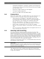
3
Camera reference
3.1
Introduction
NWC-0700, NWC-0800 and NWC-0900 are megapixel resolution
IP cameras capable of delivering crisp, low-noise images at a
video frame rate.
NWC-0700 is a 2-megapixel resolution camera having maximum
resolution of 1600 by 1200 and achieving a maximum frame
rate of 24.
NWC-0800 is a 3.1-megapixel resolution camera having maximum resolution of 2048 by 1536. It is typically viewed at 1920
by 1200 resolution with the frame rate up to 20.
NWC-0900 is a dual-sensor, day-night camera featuring a 3.1megapixel color sensor paired with a 1.3-megapixel monochrome sensor sensitive to near infrared illumination. When the
scene is well illuminated, the 3.1-megapixel sensor is selected
to deliver color images of up to 2048x1536 pixels. To provide
seamless transition between day and night modes, the color
sensor is set to default resolution of 1920x1200 pixels. In lowlight conditions, NWC-0900 can automatically switch to the 1.3megapixel (1280x1024) monochrome sensor, enabling the
delivery of clear imagery at illumination levels as low as 0.01
lux. NWC-0900 typically delivers 20 fps in day mode and over
30 fps in night mode.
All cameras are equipped with LAN connector and can deliver
image data at a maximum data rate of up to 55 Mbps. Images
are sent over the network in a compressed Motion JPEG format
using TFTP protocol with the supplied software or using HTTP
protocol with DiBos8.
Power for all cameras can be supplied via DC jack (+9 V to
+12 V) or Power over Ethernet.
!
CAUTION! Medium risk:
Never supply power via the Ethernet connection (PoE) when
power is already supplied via the power connector.
All cameras feature:
–
Automatic exposure (AE) and Gain (AGC) control
–
Automatic backlight compensation
–
Automatic multi-matrix white balance
–
50/60 Hz selectable flicker control
–
Electronic pan, tilt, and zoom (PTZ)
F.01U.064.422 | V 1.0 | 2007.03
User Manual
Bosch Security Systems
MegaPixel IP CamerasCamera reference | en
3.2
13
–
Adjustable brightness, saturation, gamma, and sharpness
–
Simultaneous delivery of full-field view and zoomed images
at video frame rate
–
Electronic image rotation by 180 degrees
–
On board motion detection
–
Auto iris on NWC-0700 and NWC-0800
Connectors
NWC-0700, NWC-0800, and NWC-0900 have the following connectors located on the rear side of the camera housing:
3.3
–
LAN connector (100 Base-T). The LAN connector also
accepts power-over-Ethernet, 48V DC over spare wires or
over data pairs. The cameras are compliant with IEEE
802.saf. The polarity is arbitrary. For a list of recommended PoE switches, see "Network Switch or Routers."
–
Via DC jack, accepting 9V-12V (+/-10%) DC supply,
500 mA. The center contact in the power connector is positive.
–
DC-iris connector. NWC-0900 does not support auto-iris so
does not have this connector.
Housing and mounting
All camera models feature durable aluminum housing. The
ambient temperature should be maintained between 0 ºC and
40 ºC. The cameras are not to be used outdoors without appropriate protective enclosures. When using outdoor an enclosure
with proper protection grade shall be used. The NWC-0900 has
two lenses and requires a 3" window to avoid shading; there is
no such limitation for the other two models.
Cameras are mounted using a ¼" x 20 threaded hole at the top
and bottom of the housing.
CAUTION!
When mounting the camera, make sure the screw that goes into
the hole is short in length, 6.35 mm (¼ inch) or less, and does
not touch the camera board.
The cameras are to be installed according to the applicable
code. The mounting means should be adequate for mounting a
½ kg (1 lb) camera.
Bosch Security Systems
User Manual
F.01U.064.422 | V 1.0 | 2007.03
14 en | Camera reference
3.4
MegaPixel IP Cameras
Network cabling
Category 5 cabling or better is recommended. All network
cabling must be installed according to applicable codes and
regulations.
3.5
Optics
The MegaPixel cameras should be used with a 1/2" or larger
optical format lens. The NWC-0900 requires two manual-iris
lenses and has a limitation on lens diameter (<38mm).
3.5.1
Using manual iris lenses
Choosing the lens correctly is very important for megapixel
cameras. A poorly selected lens may cause the image to appear
blurry when the lens iris is fully opened or closed too far. To
deliver sharp megapixel resolution images you should:
–
Use megapixel-resolution lenses;
–
Obtain best resolution and depth of focus by having the
iris slightly closed.
When setting up the camera, direct it at the scene and try closing the iris by several F-stops. At some point the image will look
its sharpest. Leave the iris closed at this value. In situations
where motion-blur can be expected, an iris value should be
selected that gives best balance of resolution, depth of focus,
and motion blur.
3.5.2
Auto-iris lenses
Standard DC auto-iris lenses can be used with the NWC-0700
and NWC-0800 cameras. Cable shall be minimum 20 mm or
longer.
3.5.3
Using auto-iris lenses
NWC-0700 and NWC-0800 are available with DC auto-iris
option. To use the DC auto-iris lens:
1.
Attach the lens to the camera.
2.
Plug the lens cable into the connector on the back of the
camera. Make sure that the lens cable is long enough.
Many DC lenses are available with short and long cable
options.
The camera will automatically detect the presence of an autoiris DC lens and start using it. Auto-iris lens operation typically
proceeds as follows:
–
If illumination is sufficient, the camera will close the iris
within half-a-minute.
F.01U.064.422 | V 1.0 | 2007.03
User Manual
Bosch Security Systems
MegaPixel IP CamerasCamera reference | en
–
15
When the iris is closed, the image should become visibly
sharper. As the iris is gradually closed, the image brightness may fluctuate slightly.
Note: You can monitor the state of the iris in the Bosch Video
System "Settings" dialog. See Section 3.5.2 Auto-iris lenses for
details.
3.6
Accessing cameras
Cameras can be accessed and controlled by means of:
3.6.1
–
Bosch Video System software
–
HTTP requests issued from DiBos8 or Internet Explorer
Supported network services
NWC-0700, NWC-0800, and NWC-0900 implement video over
TFTP and HTTP network protocols. The HTTP protocol allows
direct access to the cameras using DiBos8 and through Internet
Explorer or other HTTP-based applications.
The Bosch Video System software utilizes TFTP protocol. TFTP
protocol yields the highest live viewing frame rate.
Only 100 Mbps/1 Gbps network switches should be used. Simple hubs do not segregate network segments, and should be
replaced in existing networks to be used with MegaPixel cameras.
Bosch Security Systems
User Manual
F.01U.064.422 | V 1.0 | 2007.03
16 en | Software
4
MegaPixel IP Cameras
Software
DiBos 8 provides viewing and recording functions for standard
analog as well as Network-connected cameras. DiBos8 supports
full-resolution recording of the Bosch Megapixel cameras. At
playback, the full resolution can be utilized by zooming in on
the area of interest. In addition, live viewing supports the zoom
function to select display of detail. Refer to DiBos8 manuals for
further information.
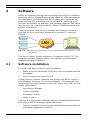
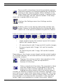
A typical system consists of a number of cameras connected
over the local or wide area network to a server PC running
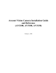
DiBos8.
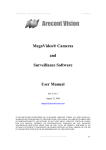
Fig. 4.1
Cameras connected over a local area network to a server PC running DiBos
The Bosch Video System software is supplied on the CD. This
program includes camera setup, live viewing, and firmware
upgrade software modules.
4.1
Software installation
To install the Bosch Video System software:
1.
Make sure your Windows XP/2K account has administrative
privileges;
2.
Run the setup.exe from the CD.
Setup process installs software and places the Bosch Application Manager shortcut icon on the desktop. The program also
installs Bosch Video System in the Start menu with links to individual applications:
–
Application Manger
–
Camera Installer
–
Firmware Loader
–
Video System
Starting the Application Manager opens a window with buttons
that access the following program functions:
–
Camera Installer: for setting up the network parameters of
individual megapixel cameras;
F.01U.064.422 | V 1.0 | 2007.03
User Manual
Bosch Security Systems
MegaPixel IP CamerasSoftware | en
17
–
Video System: live viewing for setting up the camera
parameters and motion detection function of the installed
cameras;
–
Camera Upgrade: for loading firmware upgrades into the
Megapixel cameras.
Note: The software is installed in C:\Program Files\Bosch
4.1.1
Configure firewall
As you start the application, your PC may prompt you to permit
access to the network. Bosch Video System includes two applications that need access to the network:
–
AVInstaller.exe - the camera finding and installation program;
–
LocalMachine.exe - the viewing and archiving program;
–
FirmwareLoader.exe - the firmware upgrading program.
The executables are located in the installation folder. You
should grant access to these applications when the firewall
prompts you.
If you are using the Windows XP firewall, add these three programs to the Exceptions Tab of the program.
4.1.2
Bosch Application Manager
Clicking the Bosch Application Manager icon on the user's
Desktop provides access to all programs and utilities of the
Bosch Video System. Click the Run button to start the individual program modules. Clicking Close ends operation of the program.
Fig. 4.2
Bosch Security Systems
Bosch Application Manager
User Manual
F.01U.064.422 | V 1.0 | 2007.03
18 en | Software
4.1.3
MegaPixel IP Cameras
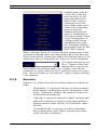
Camera installer
Camera Installer allows you to find all cameras that are present
on the local area network, assign IP addresses to the detected
cameras, and to verify that the cameras are accessible and
operational. Camera Installer saves information about installed
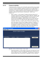
cameras into a dedicated file used by Video System. Camera
Installer supports two modes of operation - Basic and
Advanced.
–
Basic mode - In this mode, Camera Installer detects all
cameras that are within range of the broadcast request (all
cameras within the network segment of the host PC) and
automatically assigns IP addresses to the cameras. It
selects those addresses that belong to the same sub-network as the host PC itself and not yet assigned to other
network cameras. To detect and install the cameras automatically, the user should simply press the Automatic button in the Basic mode. The installer will find, configure,
and verify the operability of the cameras, and will report
installation results as shown below. Once installation is
complete, the user should press the Save/Exit button to
save the setup information and exit the Installer.
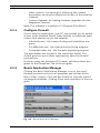
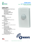
Fig. 4.3
–
Bosch Camera Installer - Basic mode
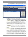
Advanced mode - In this mode, the user can detect all cameras present on the local area network and choose one or
more cameras for the installation. Furthermore, Advanced
mode allows you to issue the IP numbers of the cameras
F.01U.064.422 | V 1.0 | 2007.03
User Manual
Bosch Security Systems
MegaPixel IP CamerasSoftware | en
19
either automatically (as in Basic mode) or manually, if specific values of IP addresses are required.
Fig. 4.4
Bosch Camera Installer - Advanced mode
The "Advanced" mode provides the following set-up functions:
Automatic - this function installs the cameras and
verifies their operation. It is similar to the Automatic function in the Basic modes. However, in
the Advanced mode the Automatic installation only acts on
those devices that were highlighted by the user from among the
cameras displayed in the Present Cameras window. Select all
active cameras using the Ctrl or Shift click combination.
Find Cameras - this function will locate all cameras that are present on the local network and
are accessible by the broadcast request. At the
completion of this operation, the installer will show all detected
cameras.
Set IP - this function allows the user to program a
specific IP address in the camera. If the camera
has already been found by the Find Cameras
function, then the user should highlight that camera, type the
desired IP address in the New Camera IP window, and click Set
IP. If the camera cannot be found by the Find Cameras function
due to the fact that the existing firewall settings block broadcast requests, the user may still be able to change the camera
IP number. Type both the camera Ethernet (MAC) address and
Bosch Security Systems
User Manual
F.01U.064.422 | V 1.0 | 2007.03
20 en | Software
MegaPixel IP Cameras
desired IP number in the boxes at the top of the installer and
click the Set IP button.
Check Network - this feature will find the active
network adapters on your system. The results will
be displayed in the "Network Cards IP" section of
the Advanced window.
Clear Selections - this feature will clear/reset any
information in the "Present Cameras" section,
other than the MAC and IP addresses listed.
Save/ Exit - this feature will save the “successful”
set up information of the selected cameras and
exit the installer.
4.1.4
Installation tips
Assigning IP addresses
By using devices other than Bosch MegaPixel cameras on the
same network segment, the installer program will not find
those devices and, consequently, Automatic mode of the
installer could assign duplicate IP addresses. In this case, use
manual assignment of IP addresses in the Advanced mode.
In addition, the combination of Bosch MegaPixel cameras with
a DHCP function for other network devices on the same network segment will run the risk of creating duplicate IP
addresses in Automatic mode. Configure the DHCP server to
leave a block of IP addresses unassigned. Manually assign IP
addresses to the Megapixel cameras in this block of free IP
addresses. Finally, segmenting the network with only megapixel
cameras used in their own segment, would allow Automatic
assignment of IP addresses.
Subnets
When the megapixel camera has an existing IP address belonging to the same network but outside the subnet of the host PC,
assign a new IP address manually. After clicking "Set IP" the
program will report the correct IP address but may give a Fail
result. Select that camera and then Click the Automatic button.
The Result will now show success. Be sure to select and save all
active cameras.
Keeping a log of MAC addresses
We recommend keeping a written record of the camera's MAC
addresses and the location of their installation. This will enable
you to know the IP addresses assigned to that location when
the camera is added into the DiBos8 configuration. The MAC
and IP addresses can also be verified in the Video System
viewer. Right click in the viewer window and select "About".
F.01U.064.422 | V 1.0 | 2007.03
User Manual
Bosch Security Systems
MegaPixel IP CamerasSoftware | en
21
Now the image numbers, MAC, and IP addresses are displayed
in the pop up window.
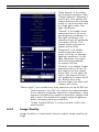
4.2
Operating Bosch Video System
Note: The Bosch Video System is provided as a tool for setting
up the megapixel cameras. The program is license free with
archiving and playback functions disabled. For extensive
recording and playback functions, the DiBos8 system should be
used.
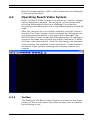
After the cameras are successfully installed using the Camera
Installer, the Video System can be activated by clicking on the
corresponding Run button in the Application Manager.The
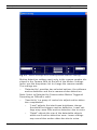
BOSCH Video System screen will then appear and, if applicable,
a pop-up message warning that the display resolution is different from camera resolution. Click OK; the images are automatically scaled to the available screen resolution. Shown below is
the Bosch Video System showing video display area for one
camera.
Fig. 4.5
4.2.1
Bosch Video System showing video display area for one camera
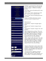
Toolbar
The toolbar of the Bosch Video System is located in the upper
portion of the screen above the video display area. It contains
the following icons:
Bosch Security Systems
User Manual
F.01U.064.422 | V 1.0 | 2007.03
22 en | Software
MegaPixel IP Cameras
Turns on/off a drop-down list of the installed cameras.
Individual cameras are disabled/enabled by left doubleclicking on the camera number. When disabled, a live
video image from the disabled camera is replaced with
a blue rectangle, and the camera number in the dropdown list is marked with a red cross.
Displays the Settings menu (see Settings section
below).
Enables a full screen display without the toolbar and
menus. Return to window display by clicking the dedicated icon in the pop-up window or by the Esc button.
Selects screen layout for viewing live video from multiple cam-
eras (from left to right):
–
single camera layout; 2x2 camera layout; 3x3 camera
layout; 4x4 camera layout;
–
10-camera layout with 2 large and 4x2 smaller images;
–
8-camera layout with 1 large, 3x1 and 1x4 smaller
images;
–
13-camera layout with 1 large, 2x2 and 4x2 smaller
images.
Depending on the chosen screen layout and the actual number
of installed cameras, the unused sections of the layout will be
empty blue screens.
Displays the archive controls (not operative in this
software version). These are explained in
Section 4.2.6 Archive.
Takes a snapshot of live video. The snapshot is taken
from the camera which is highlighted in the dropdown list of the installed cameras (see above). To
highlight another camera, left-click on the camera
number; to take the snapshot from all cameras, highlight "cameras" at the root (top) of the drop-down camera list. The snapshot file names contain the camera number, date, and time of
the snapshot. To locate/view the snapshots in the snapshot
folder, right-click anywhere on screen, then select "photo,"
F.01U.064.422 | V 1.0 | 2007.03
User Manual
Bosch Security Systems
MegaPixel IP CamerasSoftware | en
23
"browse." Alternatively, snapshots can be taken by right-clicking
on the live video image, and then selecting "photo", "save". The
directory path to the snapshot folder is specified in the Settings
menu (see Section 4.2.3 Settings).
4.2.2
Selecting full/reduced resolution and zoom
Selecting Cameras
Click the
icon to display the drop-down menu with
installed cameras. Cameras shown in the tree can be displayed
in any of the image windows of the selected screen layout.
Left-click on a camera in the tree and, while holding down the
mouse button, drag to the image window where the image
should be displayed - drop by releasing the mouse button.
Full/Half camera resolution
With single camera display selected, the camera operating resolution can be switched between full or half resolution by double-clicking on the image. When the display resolution of the PC
is lower than the camera resolution, the Video System program
will automatically scale the image down to correctly display the
full image size. Camera resolution (in pixels) is displayed in the
upper left corner of the image.
Full size/Reduced size display
In order to fit multiple video images on screen, the images are
displayed at a reduced display size. The format of the reduced
size display is determined by the chosen screen layout (see
Section 4.2.1 Toolbar).
An individual camera image can be expanded to full size of the
single image window or scaled back to its reduced resolution
display by double-clicking on the image. Image resolution (in
pixels) is displayed in the upper left corner of the image.
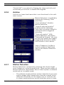
Zooming
A method for viewing more detail in the area of interest is the
zoom window (see following screenshot).
To zoom in on an area of interest, draw a rectangle with the
mouse (by left-clicking and holding down the mouse button). A
separate zoom window will open up showing live video of the
selected area at full resolution. A green outline of the selected
area will appear in the underlying reduced resolution image.
Zooming in and out is performed by pressing Page Up and Page
Down on the keyboard, or alternatively by rotating the mouse
wheel (if available). Panning of the zoomed area is performed
Bosch Security Systems
User Manual
F.01U.064.422 | V 1.0 | 2007.03
24 en | Software
MegaPixel IP Cameras
by dragging the green outline across the underlying camera
image with the mouse (by left-clicking within the outline and
holding down the mouse button), or alternatively with the keyboard arrow keys.
A maximum of four independent live zoom windows can be
opened for each camera. Each zoom window will display live
video at the image resolution provided by the camera.
Fig. 4.6
4.2.3
Bosch Video System showing the zoom window
Settings
Settings menu is displayed by clicking on the Settings button
in the toolbar.
F.01U.064.422 | V 1.0 | 2007.03
User Manual
Bosch Security Systems
MegaPixel IP CamerasSoftware | en
25
Settings menu (shown
on the left) is the toplevel menu for all settings provided in the
Bosch Video System.
Selecting one of the
menu items opens up a
lower level drop-down
menu containing
detailed settings and
options. Depending on
the camera model, some
of the listed groups of
settings may become
unavailable (for example, Day/Night settings
are available only for the
NWC-0900 camera).
Note: Selecting "Reset all" restores default settings only in the
currently displayed lower level drop-down menu, but does not
affect other groups of settings listed in the Settings menu. If no
lower level menu is displayed, the "Reset all" item is disabled.
The lower level menus contain a "Camera" field that
displays the camera number to which the settings apply. The "Camera" field can be
expanded to a drop-down list of all installed cameras for selection. The list includes an "All cameras" option to apply settings
to all cameras.
4.2.4
Exposure
Exposure is a lower-level menu to adjust exposure related settings:
–
‘Illumination’ is a group of options to adjust camera's
white balance computation to the illumination of the
scene. "Automatic" enables the camera to adjust for
illumination automatically
–
‘Lighting’ is a group of options to adjust camera's auto
exposure command to select indoor lighting flicker:
Europe/eastern Japan (50 Hz) or US/western Japan
(60 Hz).
–
‘Low Light Mode’ is a group of options selectable
from a drop-down list to adjust camera's operation
under low light conditions:
Bosch Security Systems
User Manual
F.01U.064.422 | V 1.0 | 2007.03
26 en | Software
MegaPixel IP Cameras
“High Speed" is to enable
the shortest exposure time,
"Short Exposure" between 1
and 10 ms. This option will
reduce motion blur, but may
result in a noisier video due
to a high gain under low
light conditions.
“Speed" is to enable short
exposure time of 10 ms in
good lighting conditions. In
low light situations, the
exposure time will gradually
increase to 80 ms. This
comes at the expense of
higher motion blur.
"Balanced" is to enable
medium-duration exposures of 20 ms. in average
lighting conditions. In low
light situations, the exposure time will gradually
increase to 80 ms.
"Quality" is to enable longer
exposures up to 40 ms, at
the expense of the slower
frame rate. In low light situations, the exposure time
will gradually increase to 80
ms. Motion blur may
become high, but video will
contain less noise.
"Moon Light™ is to enable very long exposures of up to 500 ms.
4.2.5
–
‘Auto exposure On/Off’ is an option to enable/disable
the in-camera automatic exposure computation. Auto
exposure enables the camera's electronic shutter and
gain control to maintain the target image brightness
under changing lighting conditions.
–
‘Single Capture Mode’ is not accessible in this software version.
Image Quality
Image Quality is a lower-level menu to adjust image quality settings.
F.01U.064.422 | V 1.0 | 2007.03
User Manual
Bosch Security Systems
MegaPixel IP CamerasSoftware | en
27
‘Quality’ (compression) adjusts the
level of JPEG compression applied
to the images in different display
modes:
"Full View" when displaying full resolution video;
"Multi View" when displaying multiple cameras at a reduced size;
"Zoom View" when displaying zoom
windows.
Slider at 100% yields best image
quality (lowest compression).
‘Adjustment’
"Brightness" adjusts image brightness.
"Sharpness" adjusts image sharpness.
"Saturation" adjusts image color saturation.
"Red" adjusts the red tint. This setting changes the target for camera's
automatic white balance computation. The effect is gradual: it takes
20-30 seconds for the camera to
adjust fully to the new setting.
"Blue" adjusts the blue tint. This setting changes the target for camera's
automatic white balance computation. The effect is gradual: it takes
20-30 seconds for the camera to
adjust fully to the new setting.
‘Speed’ adjusts the rate at which the
computer requests images from the
camera. The maximum rate is limited
by the camera (differs for different
camera models).
‘Size of Picture’ adjusts starting
coordinates and the image size.
Note: affected by "Don't update sensor window" in Advanced settings.
Bosch Security Systems
User Manual
F.01U.064.422 | V 1.0 | 2007.03
28 en | Software
MegaPixel IP Cameras
"Rotate 180" is an option for flipping the image vertically and
horizontally such that it is rotated 180 degrees.
4.2.6
Archive
Archive is a lower-level menu that is not functional in this software version.
Motion Detection is enabled by
making the following ‘Filter’
selections:
“Save all frames” disables
Motion Detection.
“Save all and mark motion”
enables motion detection.
Select this one when DiBos8 is
used with motion-triggered
recording.
“Save only motion”. With
motion detection selected to
"Detected by Camera", the camera will only output the images
triggered by the motion detection function in the camera.
Select ‘Frequency’ to Max in
order to enable a high frame
rate for the Motion Detection
window.
4.2.7
Motion Detection
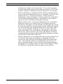
Motion detection is achieved by analyzing inter-frame brightness changes on a pixel-by-pixel basis. There are two modes of
Motion Detection supported in Bosch Video System: a software
mode and an in-camera mode.
–
The software mode performs motion detection by processing the images after transmission from the camera to the
computer and works on live images only. In contrast, the
in-camera mode performs motion detection prior to trans-
F.01U.064.422 | V 1.0 | 2007.03
User Manual
Bosch Security Systems
MegaPixel IP CamerasSoftware | en
29
mitting the images to the computer. Thus, the in-camera
motion detection significantly reduces both the CPU load
and the network load when motion detection is enabled.
–
Motion detection is enabled via the Archive settings when
one of the two following options is selected: "Save all and
mark motion" or "Save only motion." If the Archive is
enabled for "Save all frames", motion detection is disabled.
The Enabled/Disabled status is displayed in the bottom
right corner of the Motion Settings window.
–
Motion detection is computed independently in multiple
detection zones on a square grid. The largest grid supported for any Bosch camera model and image size is 8 by
8. The actual grid for any particular model is determined by
the chosen zone size (a drop-down list in the lower right
corner of the Motion Settings screen) and the camera's
pixel resolution. The actual grid is displayed in the lower
left corner. When motion is present, the Motion Settings
window displays green marks (selectable between crosses
and boxes) in the zones affected.
–
Motion detection can be masked to block motion detection
in some of the zones by drawing a rectangle with the
mouse (by left-clicking and holding down the mouse button). The masked areas are marked with red crosses. A
more complex shape can be created by drawing multiple
rectangles. Erasing the mask (or part of the mask) is done
by drawing a rectangle with the right mouse button.
Bosch Security Systems
User Manual
F.01U.064.422 | V 1.0 | 2007.03
30 en | Software
MegaPixel IP Cameras
Fig. 4.7
Motion Settings menu showing motion detection settings
Motion detection settings apply only to the camera number displayed in the Camera field on the left of the Motion Settings
menu: use the drop-down list to change the camera number.
The settings are:
–
‘Detected by’ provides two selected options, the software
motion detection and the in-camera motion detection.
Note: Select to Detected by Camera when Motion Triggered
Recording on DiBos8 is used.
–
‘Sensitivity’ is a group of controls to adjust motion detection computation:
–
"Level" adjusts the inter-frame brightness change
threshold that triggers motion detection. Lower settings may cause false motion detection due to noise.
–
"Detail" adjusts the size of the detectable objects
within each motion detection zone. Lower settings
may cause false motion detection due to noise.
F.01U.064.422 | V 1.0 | 2007.03
User Manual
Bosch Security Systems
MegaPixel IP CamerasSoftware | en
–
4.2.8
31
"Limit" serves as a guard against false triggering due
to a sudden overall change in lighting that would trigger motion detection in a large number of zones simultaneously. If the number of zones activated
simultaneously is larger than "Limit," motion detection
will be blocked. This parameter cannot exceed the
number of zones in the grid (displayed in the lower
left corner of Motion Settings).
Save to
A lower level Save to menu allows one to specify the directory
path for video archives and snapshot images. Note that the
other selections in this menu are for archiving, which is not
available in this software version.
Bosch Security Systems
User Manual
F.01U.064.422 | V 1.0 | 2007.03
32 en | Software
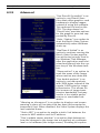
4.2.9
MegaPixel IP Cameras
Advanced
"Use DirectX if possible" is an
option to use DirectX functions that utilize graphics card
hardware to display images,
instead of using the software.
This reduces the load on the
CPU. The drop-down list
"DirectX size" provides options
for the graphics area size supported by DirectX.
"Auto - Startup" is an option to
start the Bosch Video System
automatically when Windows
starts up.
"RealTime if folded" is an
option to continue running the
Bosch Video System application at the top priority level in
the Windows Task Manager,
after the application was minimized and placed into the system tray of the Windows task
bar.
"Show motion" is an option to
mark the areas of the image
where motion was detected.
"Use double packets" is an
option to use data packets
with 2904 bytes instead of the
regular 1450 bytes for image
transmission. This allows for
the increase of image transmission bandwidth, but may
lead to a less stable performance on overloaded networks.
"Warning on disconnect" is an option to display a red screen
warning in place of live video that has been disconnected or
temporarily lost. When disabled, the Video System displays the
last captured frame.
"Static ARP" is an option to enable a static link between the
camera's MAC address and its IP address.
“Don't update sensor window" is an option that determines
how the changes to the image size are applied: at a software
level or in hardware (the image sensor). Enabling this option
F.01U.064.422 | V 1.0 | 2007.03
User Manual
Bosch Security Systems
MegaPixel IP CamerasSoftware | en
33
helps to avoid conflicts when multiple users are viewing the
same camera (each will be able to set a different image size).
Alternatively, disabling this option allows for increase of the
camera frame rate due to a smaller image size.
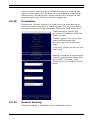
4.2.10
Permission
Permission (access control) is used to set up password-protected access to the Bosch Video System. For any user there
are three levels of access available (from the drop-down list):
“Administrator" grants full
access to all features of Bosch
Video System.
”Viewer" grants access to live
video and browsing the
archives, but not to the settings.
"Live only" grants access to live
video only.
Adding, changing, and removing
users is done via the three buttons "Add", "Change", and
"Remove" on the bottom of the
menu.
4.2.11
Remote Viewing
Remote Viewing is disabled in this software version.
Bosch Security Systems
User Manual
F.01U.064.422 | V 1.0 | 2007.03
34 en | Software
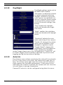
4.2.12
MegaPixel IP Cameras
Day/Night
Day/Night settings apply only to
the NWC-0900 camera.
"Automatic" enables the camera
to switch automatically from
daylight conditions (using the
color sensor) to nighttime conditions (using the monochrome
sensor) and vice versa, based
on the Threshold settings (see
below).
"Day" enables the daylight
mode and disables the nighttime mode.
"Night" enables the nighttime
mode and disables the daylight
mode.
‘Threshold’ adjusts the automatic switching of the camera:
"Switch At" changes the adjustment level of darkness from
daylight to nighttime mode.
"Toggle Guard" changes the
adjustment level of brightness
from nighttime to daylight
mode. Toggle Guard set to 0% corresponds to "Switch At" set
to 100%. Toggle Guard should be adjusted to prevent mode
toggling during the transitional lighting.
4.2.13
Auto-Iris
The Auto-Iris menu allows monitoring the state of the automatic
DC iris. If the scene is too dark, the camera will open the iris
fully. This allows more light onto the sensor and will substantially improve the low-light performance. If the scene is too
dark when the camera is started, the camera will not close the
iris until there is enough illumination.
Camera DC auto-iris can be configured using Auto-Iris menu:
F.01U.064.422 | V 1.0 | 2007.03
User Manual
Bosch Security Systems
MegaPixel IP CamerasSoftware | en
35
‘Auto-Iris’ can be disabled by
un-checking "Enabled". The
camera will open the iris fully
and have electronic auto-exposure enabled. This configuration
is identical to using a manual
lens.
Auto-iris will open the lens fully
once the in-camera analog gains
exceed a certain level. The
“Gain” scroll bar adjusts the
point where the auto-iris will
open fully: the higher the gain,
the later the auto-iris will open
as the illumination diminishes.
The ‘Status’ of the auto-iris is
displayed on a color panel,
which has six different states:
"Disabled" - the auto-iris is
either disabled by un-checking
the "Enabled" check box, or is
not present;
"Evaluating" - the camera is preparing to close the iris;
"Too Dark" - the camera cannot
close the iris because the scene illumination is too low;
"Closing" - the iris is closing down by the number of F-stops
appropriate for the illumination level;
"Closed" - the iris is closed to the correct F-stop;
"Opening" - the iris is opening.
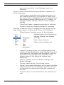
4.2.14
Right-click menu
Right-clicking anywhere within the Bosch Video System screen
allows you to invoke an additional menu:
‘Show’ presents two options:
–
"Archive" is not functional in this software version.
–
"Photos" enables access to snapshots taken with the
Bosch MegaPixel cameras. The default snapshots
location is: My Documents\My Pictures\BOSCH Photos -- a different directory path to the snapshot direc-
Bosch Security Systems
User Manual
F.01U.064.422 | V 1.0 | 2007.03
36 en | Software
MegaPixel IP Cameras
tory can be specified in the Settings menu (see
Settings).
‘Photo’ enables saving and printing individual snapshots, as
well as browsing:
–
"Save" takes a snapshot of live video and saves it in
the snapshot directory. The snapshot is taken from
the camera that is highlighted in the drop-down list of
the installed cameras (see Section 4.2.1 Toolbar). To
highlight another camera, left-click on the camera
number.
–
"Save/Print" takes a snapshot and prints it instantly.
–
"Browse" opens the snapshot folder for browsing.
‘Settings’ enables access to changing the main groups of settings as described in Settings (see Section 4.2.3 Settings).
–
"Miscellaneous" enables access to the following:
Authentication (see Permission);
Remote Viewing (see Remote
Viewing);
Save to (see Save to);
Advanced (see Advanced).
–
"Camera" enables access to a combined menu that
includes: Image Quality (see Image Quality), Exposure
(see Exposure), Day/Night (see Day/Night), Auto-Iris
(see Auto-Iris) and Archive (see Archive). It also
includes some of the Advanced settings (see
Advanced).
–
"Motion" enables access to Motion Settings (see
Motion Settings).
–
"Printer" opens up the "Print Setup" menu.
–
"Dump" logs camera settings to a file named LocalMachine.ini located in the installation directory. Technical Support may request providing the contents of
this file.
–
"Import license" is not functional in this software version.
F.01U.064.422 | V 1.0 | 2007.03
User Manual
Bosch Security Systems
MegaPixel IP CamerasSoftware | en
37
‘Hide’ minimizes the Bosch Video System application and hides
it in the system tray of the Windows task bar.
‘Log off’ logs off current user and hides the Video System application.
‘Exit’ exits the Video System application.
‘About’ shows the version of the Bosch Video System software
and the additional information for each of the installed camera(s): camera type, firmware and hardware version, MAC and
IP addresses.
4.2.15
User authentication
Bosch Video System allows setting up password-protected
access (see Section 4.2.10 Permission). If one or more user
accounts were created, the Bosch Video System will display a
log-in dialog prompting for the user name and password, as
shown.
4.2.16
Language selection
Bosch Live Video System supports interfaces in English; other
languages will be added in future releases. Press the F2 key to
bring up the language menu.
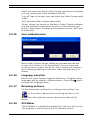
4.2.17
Browsing archives
Archive browsing is enabled by clicking on the archive icon
in the toolbar. Because the archiving function is not
available in this software version, the archive files will be
empty.
4.2.18
AVI Maker
The AVI Maker is intended for making AVI clips from the Archive.
The program is not functional in this software version.
Bosch Security Systems
User Manual
F.01U.064.422 | V 1.0 | 2007.03
38 en | Software
4.2.19
MegaPixel IP Cameras
HTTP access
Bosch MegaPixel cameras can be accessed from Internet
Explorer, via the in-camera web page. The web page allows
viewing live images and changing some of the camera settings.
The web pages can be addressed by typing in your browser’s
Address bar:
http://ip_address (or) http://ip_address/index.html
Individual images can be requested from Bosch MegaPixel cameras using a HTTP string.
Please refer to the DiBos8 section of this manual for the string
parameters.
4.2.20
Firmware Loader - Upgrading the cameras
Bosch MegaPixel cameras are upgradeable in the field.
The Firmware Loader is the software tool that loads the
upgrade files into the cameras.
Always follow the instructions that come with the upgrade file.
4.3
DiBos8 set-up for Bosch Megapixel
cameras
DiBos8 is using HTTP requests for live viewing and recording of
Megapixel images.
Though DiBos8 may not have display capabilities to view megapixel camera images in full resolution, it does, however, process
and record the images in megapixel format. Detail of live and
recorded images can be viewed using the DiBos8 zoom function.
The megapixel camera can send up to 5 streams to the same or
different clients. The streams can have different frame rates
and resolution. In order to save storage space, DiBos8 could
record a high resolution low frame rate image of a camera and,
at the same time, record images of the area of interest at a high
frame rate. In this case, DiBos8 creates two cameras with the
same IP address but with different HTTP parameters.
For detail of DiBos8 installation, refer to its respective manuals
and instructions.
4.3.1
Preparing Megapixel cameras for DiBos8
For sending the motion trigger signal correctly to DiBos8, you
should check that the megapixel camera archive and motion
detector settings are correct.
F.01U.064.422 | V 1.0 | 2007.03
User Manual
Bosch Security Systems
MegaPixel IP CamerasSoftware | en
39
In the settings menu of the Bosch Video System software, first
select ‘Archive’ and verify that the Filter is selected to "Save all
and mark motion". Next, select ‘Motion Detection’ and verify
that "Detected by Camera" is selected and the motion detection
parameters are set. The megapixel camera sends the ‘Motion
Detection’ trigger to the IP address of the client that last
accessed the camera.
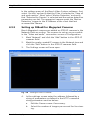
4.3.2
Setting up DiBos8 for Megapixel Cameras
Bosch Megapixel cameras are added as JPEG IP cameras in the
Network Devices section. The screens to set up are accessible
in the “Video and audio” connection screen of Configuration.
1.
Mark ‘Network’ and click the "Add" button in the JPEG IP
cameras field.
2.
Mark the newly created IP camera in the Network tree and
click the "Edit" button in the JPEG IP cameras field.
3.
The Settings screen will now open.
Fig. 4.8
4.
Settings screen in DiBos8
In the settings screen enter the address followed by a
string of parameters as defined in the HTTP command
string parameters section below:
a.
Edit the Camera name if necessary.
b.
Select the number of images per second for live viewing.
Bosch Security Systems
User Manual
F.01U.064.422 | V 1.0 | 2007.03
40 en | Software
MegaPixel IP Cameras
c.
Check "Motion camera" if motion-triggered recording
is used with this camera.
d.
Enter the port number as defined in the HTTP command string.
e.
For “On command” enter: ismotion
f.
For Off command enter: nomotion
g.
Click OK to save the entered configuration.
All remaining DiBos8 recording settings are standard.
4.3.3
HTTP command string parameters
The generic HTTP command string has the following format:
http://<ip_address>/
image?res=<resolution_value>&x0=<x0_value>&y0=
<y0_value>&x1=<x1_value>&y1=<y1_value>&qualty=
<quality_value>&doublescan=<doublescan_value> [&mdn=
<port_no>]
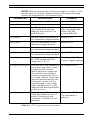
Table 3.1 describes the parameters.
The requested image can have a smaller size (electronic zoom
function) than the camera sensor size. The image size is defined
by the x0, y0, x1, and y1 coordinates on the sensor. For the
NWC-0700 and NWC-0800, the coordinates are defined in pixels. The NWC-0900 has two sensors of differing resolution. Set
the x and y coordinates for the 3.1 MegaPixel sensor.
x0 and y0
These two parameters define the left-hand, top-corner point of
the requested image. For the NWC-0700 and NWC-0800 the values are in pixels.
x1 and y1
These two parameters define the right-hand, bottom-corner
point of the requested image on the imaging device. For the
NWC-0700 and NWC-0800 the values are in pixels.
F.01U.064.422 | V 1.0 | 2007.03
User Manual
Bosch Security Systems
MegaPixel IP CamerasSoftware | en
41
NOTE! DiBos8 automatically scales an image to a 4 (H) x 3 (V)
aspect ratio for display. Always maintain the selected image
area to be displayed at a 4x3 aspect ratio.
PARAMETER
DESCRIPTION
COMMENT
<ip_address>
The IP address of the camera e.g. 192.168.2.75
/image?
Image request command
<resolution_value>
Specifies whether the camera should decimate the
image by the factor of 2 in
each direction
<x0_value>
The left hand coordinates of default: x0=0
the requested image window
<y0_value>
The top coordinates of the
requested image window
<x1_value>
The right hand coordinates of e.g. x1=1600
the requested image window
<y1_value>
The bottom coordinates of
e.g. y1=1200
the requested image window
<quality_value>
The compression quality of
the JPEG image with the
range from 1 to 21
full or half, e.g. res=
half=> an image with
1600x1200 will
become 800x600
default: y0=0
default: quality=12.
21 gives highest quality
<doublescan_value> Doublescan is the parameter e.g. doublescan=0
that allows the user to specify whether the camera
should delay the image output until the new image is
scanned (doublescan=0) or
the image request should be
serviced immediately by outputting the content of the
current image in the image
buffer (doublescan=1) (the
image will be displayed faster
on the screen)
The camera sends "ismotion" e.g. port_no=3028
to the specified port No. if
This parameter is
motion is detected and
optional.
"nomotion" if motion is not
detected.
<port_no>
Table 4.1 HTTP command string parameters
Bosch Security Systems
User Manual
F.01U.064.422 | V 1.0 | 2007.03
42 en | Software
MegaPixel IP Cameras
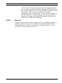
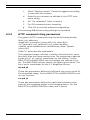
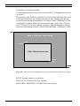
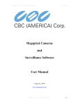
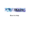
Example of zoomed image:
The drawing below shows the size of the 3.1 megapixel sensor
in pixels.
The sensor has 2048 px (pixels) in the horizontal direction and
1536 px vertically. An image request at full image size would
have the following parameters: x0=0&y0=0&x1=2048&y1=1536.
Taking the shaded area as a zoomed image, with size 1024 px
(H) X 768 px (V) at the drawn location, the parameters would
have the following values: x0=410&y0=492&x1=1434&y1=1260.
y=0
2048 x 1536 pixel sensor area
x=410
y=492
1024 x 768 pixel zoom area
y=1260
x=1434
y=1536
x=2048
Fig. 4.9
Size of the 3.1 megapixel sensor area in pixels and percentage.
NOTE: Image sensor resolution:
NWC-0700: 1600x1200 (hxv) pixels
NWC-0800, NWC0900: 2048x1536 (hxv) pixels
F.01U.064.422 | V 1.0 | 2007.03
User Manual
Bosch Security Systems
Bosch Security Systems
Robert-Koch-Straße 100
D-85521 Ottobrunn
Germany
www.boschsecuritysystems.com
© Bosch Security Systems, 2007