1
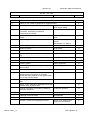
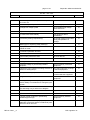
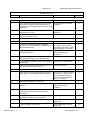
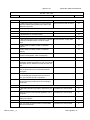
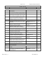
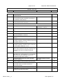
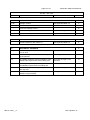
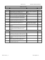
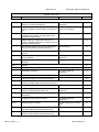
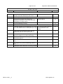
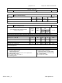
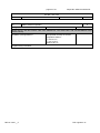
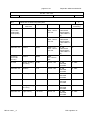
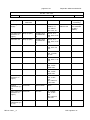
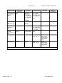
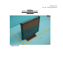
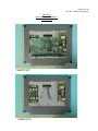
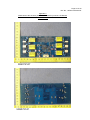
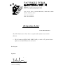
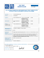
CB TEST
CERTIFICATE
Ref. Certificate No.
SG-2499M2
IEC SYSTEM FOR MUTUAL RECOGNITION OF TEST CERTIFICATES
FOR ELECTRICAL EQUIPMENT (IECEE) CB SCHEME
Issued by:
TÜV SÜD PSB Pte Ltd
Product:
LCD Monitor
Applicant:
DIVA Laboratories Ltd. 7TH FL-8, 351 CHUNG
SHAN RD, SEC 2,
CHUNG HO, TAIPEI
HSIEN 235 TAIWAN
DIVA Laboratories
7TH FL-8, 351 CHUNG
Ltd.
SHAN RD, SEC 2,
CHUNG HO, TAIPEI
HSIEN 235 TAIWAN
DIVA Laboratories Ltd. 7TH FL-8, 351 CHUNG
SHAN RD, SEC 2,
CHUNG HO, TAIPEI
HSIEN 235 TAIWAN
Manufacturer:
Factory:
nb: Additional factory
information on page 2
Taiwan
Taiwan
Taiwan
Rating and principal
characteristics:
100-240V~, 50/60Hz, 1.2-0.6A, Class I
Trade mark (if any):
DIVA
Model/Type
reference:
GODx7yzMI and GOKx7yzMI (where x = 8 or 9, y = 0-9 or A-Z and z = A-Z)
Additional information:
Certificate SG-2499 issued 2006-08-07 and Certificate SG-2499M1 issued
2006-10-25 are replaced by this version due to add model, trademark,
alternate metal enclosure and base and alternate classification according to
the degree of protection against ingress of water.
Sample of product
tested to be in
conformity with IEC:
60601-1(ed.2);am1;am2
Test Report Ref. No:
55S072147/NCH/CZ
This CB Test Certificate is issued by the National Certification Body:
TÜV SÜD PSB Pte Ltd
1 Science Park Drive, Singapore 118221
Signed by: Teo Kim Hock
Date of issue: 2007-11-26
1/2
IEC SYSTEM FOR CONFORMITY
TESTING TO STANDARDS FOR
SAFETY OF ELECTRICAL
EQUIPMENT (IECEE) CB SCHEME
Ref. Certificate No.
SG-2499M2
LUXON Systems Corporation
No. 161, Hsing Jen Road, Tamshui Taipei Hsien,
Taiwan
Additional information (if necessary)
This CB Test Certificate is issued by the National Certification Body:
TÜV SÜD PSB Pte Ltd
1 Science Park Drive, Singapore 118221
Signed by: Teo Kim Hock
Date of issue: 2007-11-26
2/2
page 2 of 27
Report No. 55S072147/NCH/CZ
Copy of marking plate:
See Appendix 14 to 19 of Test Report Ref. No.: 55S061674/NCH/CZ, Appendix 5 of Test Report Ref. No.:
55S062158/NCH/CZ and Appendix 5 of this Test Report.
TRF No. I6011__C
TRF originator: UL
page 3 of 27
Report No. 55S072147/NCH/CZ
GENERAL INFORMATION
Test item particulars (see also clause 5):
Classification of installation and use ....................................... :
Portable
Supply connection ................................................................... :
Appliance coupler
Accessories and detachables parts included in the evaluation
................................................................................................. :
None
Options included ..................................................................... :
None
Possible test case verdicts:
- test case does not apply to the test object ................. :N / A
N
- test object does meet the requirement ........................ :Pass
P
- test object does not meet the requirement .................. :Fail
F
Abbreviations used in the report:
- normal condition .......................................................... :N.C.
- operational insulation................................................... :OP
- basic insulation between parts of opposite polarity ..... :BOP
- double insulation.......................................................... :DI
- single fault condition ................... :S.F.C.
- basic insulation ........................... :BI
- supplementary insulation ............ :SI
- reinforced insulation.................... :RI
General remarks:
"This report is not valid as a CB Test Report unless appended to a CB Test Certificate issued by a
NCB, in accordance with IECEE 02".
"(see Attachment #)" refers to additional information appended to the report.
"(see appended table)" refers to a table appended to the report.
Throughout this report a point is used as the decimal separator.
The tests results presented in this report relate only to the object tested.
This report shall not be reproduced except in full without the written approval of the testing laboratory.
List of test equipment must be kept on file and available for review.
Summary of contents provided on the last page of this report.
TRF No. I6011__C
TRF originator: UL
page 4 of 27
Report No. 55S072147/NCH/CZ
General product information and considerations:
Remark 1: This modify report is to supplement the earlier reports:
-
Test Report No. 55S061674/NCH/CZ, dated 31 July 2006 (CB Ref. Certificate No.:
SG-2499).
-
Test Report No. 55S062158/NCH/CZ, dated 19 October 2006 (CB Ref. Certificate No.:
SG-2499M1)
Remark 2: The modifications made on this report were as below:
1. Add model: ER-191.
2. Add Trademark: AG neovo (for model: ER-191)
3. Add alternate metal enclosure and base.
4. Add alternate classification according to the degree of protection against ingress of water:
IPX2 (only for model: ER-191).
Remark 3:
Model: GOKx7yzMI is identical to Model: GODx7yzMI except for the model designation.
Model: ER-191 is similar to models: GOKx7yzMI & GODx7yzMI except for model designation ,
enclosure and base.
(Refer to Appendix 6 for the identity declaration letter)
x = 8 for 18” TFT panel size, x = 9 for 19” TFT panel size,
y = 0-9 or A-Z for different sale-area and different customers,
z = A-Z for different TFT panel supplier.
Remark 4: Components used for each model are as below:
Remark 5: All tests were conducted on Model: ER-191 unless otherwise specified and is the
representative of the other models.
TRF No. I6011__C
TRF originator: UL
page 5 of 27
Report No. 55S072147/NCH/CZ
IEC 601 + Am. 1& 2
Clause
Requirement + Test
5
CLASSIFICATION
P
5.1
Type of protection against electric shock
P
5.2
5.4
5.5
5.6
Class I equipment.
P
Class II equipment
Class I equipment.
N
Internally powered equipment
Class I equipment.
N
Degree of protection against electric shock
N
No applied part.
N
Type BF applied part
N
Type CF applied part
N
As the equipment is not
Not classified - no applied parts
intended to be connected to the
patient and does not have any
patient applied parts, it is
should not be marked with the
type B applied part symbol.
Nevertheless, the product
complies with the requirements
for type B applied part
concerning protection against
electric shock.
Classification according to the degree of protection IPX2, only for model: ER-191.
against ingress of water as detailed in the current (see separate test report)
edition of IEC 529 (see 6.1.1) .................................. ::
P
P
Methods of sterilization or desinfection
Not applicable.
N
Equipment not suitable for use in the presence of
flammable mixtures
The equipment is not AP or
APG category equipment.
N
Category AP equipment
N
Category APG equipment
N
Mode of operation:
P
-continuous operation
TRF No. I6011__C
Verdict
Class I equipment
Type B applied part
5.3
Result - Remark
Continuous operation.
P
-short-time operation, specified operation; period... :
—
-intermittent operation, specified operation; rest
period ....................................................................... :
—
-continuous operation with short-time, stated
permissible loading time .......................................... ::
—
-continuous operation with intermittent, stated
permissible loading/rest time ................................... :
—
TRF originator: UL
page 6 of 27
Report No. 55S072147/NCH/CZ
IEC 601 + Am. 1& 2
Clause
Requirement + Test
6
Identification, marking and documents
P
6.1
Marking on the outside of equipment or equipment parts
P
c) Markings of the specific power supply affixed
Result - Remark
Verdict
No applicable. No specific
power supply affixed.
d) If marking is not practicable due to size or nature Not applicable.
of enclosure, information is included in
accompanying documents
N
e) Name and/or trademark of the manufacturer or DIVA Laboratories Ltd. or
supplier .....................................................................: DIVA
P
f) Model or type reference ........................................: GODx7yzMI, GOKx7yzMI.
ER-191
(see Remark 4 on page 4)
P
g) Rated supply voltages or voltage range(s)
100-240 V~
P
Number of phases ....................................................: Single phase.
N
Type of current .........................................................: AC
P
50/60 Hz
h) Rated frequency or rated frequency range(s)
(Hz) ..........................................................................:
P
j) Rated power input (VA, W or A)............................: 1.2-0.6 A
P
k) Power output of auxiliary mains socket-outlets
No socket-outlet.
N
l) Class II symbol
Class I equipment.
N
Symbol for degree of protection against ingress of IPX2, wording in manual.
water provided ..........................................................:
P
Symbol for protection against electric shock ...........: No applied part.
N
If equipment has more than one applied part with
different degrees of protection, the relevant
symbols are clearly marked on such applied parts,
or on or near relevant outlets
N
Symbol for protection of defibrillation-proof applied
parts
No defibrillation applied parts.
Symbol 14 from Table DI for defibrillation-proof with
protection partly in patient cable
m) Mode of operation (if no marking, suitable for
continuous operation)
N
N
Continuous operation.
N
n) Types and rating of external accessible fuses ....: No external fuses.
N
p) Ratings of external output ...................................: Not applicable.
N
q) Symbol for physiological effect(s):
N
- attention, consult accompanying documents
TRF No. I6011__C
N
Symbol 14 of Table DI was
used in the User Manual.
TRF originator: UL
P
page 7 of 27
Report No. 55S072147/NCH/CZ
IEC 601 + Am. 1& 2
Clause
Requirement + Test
Verdict
- non-ionizing radiation, or symbols as adopted by
ISO or IEC 417
N
r) Anaesthetic-proof symbol: AP or APG .................: Not of category AP or APG.
N
s) Dangerous voltage symbol
No accessible high voltage
terminal devices.
N
t) Special cooling requirements
No such devices.
N
u) Limited mechanical stability
The equipment did no
overbalance.
P
v) Protective packing requirement(s)
No special measure was taken
during transportation or
storage.
N
- Marking(s) for unpacking safety hazard(s)
N
- Equipment or accessories supplied sterile,
marked as sterile
N
y) Potential equalization terminal
N
- Functional earth terminal
N
z) Removable protective means
6.2
Result - Remark
No such devices.
N
Durability of marking test
P
Marking on the inside of equipment or equipment parts
P
a) Nominal voltage of permanently installed
equipment
N
Not permanently connected
equipment.
b) Maximum power loading for heating elements or No heating elements or lamps
holders for heating lamps
inside the equipment.
N
c) Dangerous voltage symbol
Provided on the inverter,
located inside the equipment.
P
d) Type of battery and mode of insertion
No battery inside the
equipment.
N
- Marking referring to accompanying documents
used for battery not intended to be changed by the
operator
N
e) Fuses accessible with a tool identified either by Fuses were not accessible.
type and rating or by a reference to diagram
N
f) Protective earth terminal
Appliance inlet used.
P
g) Functional earth terminal
No functional earth terminal.
N
h) Supply neutral conductor in permanently
installed equipment (N)
Not permanently installed
equipment.
N
j) Markings required in 6.2 f), h), k) ,and l) remain
visible after connection and are not affixed to parts
which have to be removed
TRF No. I6011__C
N
TRF originator: UL
page 8 of 27
Report No. 55S072147/NCH/CZ
IEC 601 + Am. 1& 2
Clause
6.3
Requirement + Test
Result - Remark
- Markings comply with IEC 445
See below.
Verdict
P
Not permanently connected
k) For permanently connected devices the supply
equipment.
connections are clearly marked adjacent to the
terminals (or in accompanying documents for small
equipment)
N
l) Statement for suitable wiring materials at
temperatures over 75 °C
Not permanently connected
equipment.
N
n) Capacitors and/or circuit parts marked as
required in Sub-clause 15c
No such devices.
N
Marking of controls and instruments
P
a) Mains switch clearly identified
See below.
P
- ON and OFF positions marked according to
Symbols 15 and 16 of table D1 or indicated by an
adjacent indicator light
The line “I” for “ON” and circle
“O” for OFF were provided
according to IEC 60417-1-IEC5007 and 60417-1-IEC-5008.
P
b) Indication of different positions of control
devices and switches
Indication of control devices
were provided on the
equipment.
P
c) Indication of the direction in which the magnitude
of the function changes, or an indicating device
6.4
f) The functions of operator controls and indicators
are identified
Provided in the user manual.
P
g) Numeric indications of parameters are in SI
units except for units listed in Am. 2
Provided in SI units.
P
Symbols
Used symbols comply with Appendix D or IEC 417
and/or IEC 878 or ISO publications (if applicable)
6.5
P
The line “I” for “ON” and circle
“O” for OFF for mains switch
were provided according to
IEC 60417-1-IEC-5007 and
60417-1-IEC-5008.
Colors of the insulation of conductors
a) Protective earth conductor has green/yellow
insulation
TRF No. I6011__C
N
P
P
The protective earth conductor
is green/yellow color
insulation.
P
b) All insulations of internal protective earth
conductors are green/yellow at least at their
terminations
P
c) Only protective or functional earthing, or potential
equalization conductors are green/yellow
P
d) Color of neutral conductor ....................................: Not provided with the power
supply cord.
N
e) Colors of phase conductor(s) ..............................: Not provided with the power
supply cord.
N
TRF originator: UL
page 9 of 27
Report No. 55S072147/NCH/CZ
IEC 601 + Am. 1& 2
Clause
Requirement + Test
Result - Remark
Verdict
- Compliance with IEC 227 and IEC 245
f) Additional protective earthing in multi-conductor,
cords are marked green/yellow at the ends of the
additional conductors
6.6
N
Multi-conductor cord not used.
Medical gas cylinders and connections
a) In accordance with ISO ISO/R 32
N
N
No such device.
N
b) Identification of connection point
N
Indicator lights and push-buttons
N
a) Red indicator lights used exclusively to indicate No red indicator or light used.
a warning of danger and/or a need for urgent
action
N
- Yellow used to indicate caution or attention
required
N
- Yellow used to indicate caution or attention
required
N
b) Color red used only for push-buttons by which a
function is interrupted in case of emergency
N
6.8
ACCOMPANYING DOCUMENTS
P
6.8.1
Provided in the user manual.
Equipment accompanied by documents
containing at least instructions for use, a technical
description and an address to which the user can
refer
P
Classifications specified in Clause 5 included in
both the instructions for use and the technical
description
Provided in the user manual.
P
Markings specified in Sub-clause 6.1 included in
the accompanying documents if they have not
been permanently affixed to equipment
Provided on the equipment.
N
Warning statements and the explanation of
warning symbols provided in the accompanying
documents
Provided in the user manual.
P
6.7
6.8.2
TRF No. I6011__C
Instructions for use
P
a) General information provided in instructions for
use
Provided in the user manual.
P
- state the function and intended application of the
equipment
Provided in the user manual.
P
- include an explanation of: the function of controls, Provided in the user manual.
displays and signals
P
- the sequence of operation
Provided in the user manual.
P
- the connection and disconnection of detachable
parts and accessories
Provided in the user manual.
P
TRF originator: UL
page 10 of 27
Report No. 55S072147/NCH/CZ
IEC 601 + Am. 1& 2
Clause
Requirement + Test
Result - Remark
Verdict
- the replacement of material which is consumed
during operation
No replacement material.
- information regarding potential electromagnetic or Provided in the user manual.
other interference and advice regarding avoidance
P
- include: indications of recognized accessories,
detachable parts and materials, if the use of other
parts or materials can degrade minimum safety
N
- instructions concerning cleaning, preventive
inspection and maintenance to be performed
including the frequency of such maintenance
Provided in the user manual.
General information provided in instructions:
6.8.3
TRF No. I6011__C
N
P
P
- information for the safe performance or routine
maintenance
Routine maintenance is not
necessary.
N
- parts on which preventive inspection and
maintenance shall be performed by other persons
including the periods to be applied
Preventive inspection and
maintenance are not
necessary.
N
- explanation of figures, symbols, warning
statements and abbreviations on the equipment
Provided in the user manual.
P
c) Signal output or signal input parts intended only Provided in the user manual.
for connection to specified equipment described
P
d) Details about acceptable cleaning, disinfection
or sterilization methods included
No direct contact to the
patient.
N
e) Warning statement for mains operated
equipment with additional power source
No additional power source.
N
f) A warning to remove primary batteries if
equipment is not likely to be used for some time
No battery inside the
equipment.
N
g) Instructions to ensure safe use and adequate
maintenance of rechargeable batteries
No battery inside the
equipment.
N
h) Identification of specified external power
supplies or battery chargers necessary to ensure
compliance with the requirements of IEC 601-1
No such device.
N
j) Identification of any risks associated with the
disposal of waste products, residues, etc.
N
- Advice in minimizing these risks
N
Technical description
P
a) All characteristics essential for safe operation
provided
Provided in the user manual.
P
b) Required type and rating of fuses utilized in the
mains supply circuit external to permanently
installed equipment
Not permanently connected
equipment.
N
TRF originator: UL
page 11 of 27
Report No. 55S072147/NCH/CZ
IEC 601 + Am. 1& 2
Clause
Requirement + Test
Result - Remark
Verdict
- Instructions for replacement of interchangeable
and/or detachable parts which are subject to
deterioration during normal use
No such device.
N
c) Instructions or reference information for repair
of equipment parts designated by the
manufacturer as repairable provided
No user repairable parts.
N
d) Environmental conditions for transport and
storage specified in accompanying documents
and marked on packaging
Temperature: -20 C to +60 C
o
o
P
Humidity: 10% to 90%RH
Air Pressure: 187 to 1060hPa
P
16
ENCLOSURES AND PROTECTIVE COVERS
16a
Equipment enclosed to protect against contact
with live parts, and with parts which can become
live (finger, pin, hook test)
In compliance with the leakage
current requirements.
Insertion or removal of lamps - protection against
contact with live parts provided
No lamps inside the
equipment.
P
(see appended table)
N
16b
Opening in a top cover positioned that
Components enclosed in the
accessibility of live parts by a test rod is prevented EUT cannot be touched by the
test rod.
P
16c
Conductive parts accessible after the removal of handles, knobs, levers
N
- have a resistance of not more than 0.2
No such parts.
N
- separated from live parts by one of the means
described in Sub-clause 17g
N
No accessible internal
components
N
16d
Parts with voltage exceeding 25V a.c. or 60V d.c.
which cannot be disconnected by external mains
switch or plug protected against contact
16e
Removable enclosures protecting against contact with live parts.
P
- Removal possible only with the aid of a tool
P
16f
TRF No. I6011__C
The removal of the enclosure
needs the aid of tool.
- Use of automatic device making parts not live
when the enclosure is opened or removed
N
- Exception 16e applied to the following parts .......:
N
Openings for the adjustment of controls using a
tool. The tool not able to touch basic insulation or
any live parts
No pre-set control which may
be adjusted during normal
used.
TRF originator: UL
N
page 12 of 27
Report No. 55S072147/NCH/CZ
IEC 601 + Am. 1& 2
Clause
Requirement + Test
18
PROTECTIVE EARTHING, FUNCTIONAL EARTHING AND POTENTIAL
EQUALIZATION
P
18a
Accessible parts of Class I equipment separated
from live parts by basic insulation connected to
the protective earth terminal
P
18b
Protective earth terminals suitable for connection
to the protective earth conductor
18e
Potential equalization conductor
- Readily accessible
18f
Result - Remark
Verdict
Appliance inlet used.
P
N
No connection to potential
equalization conductor.
N
- Accidental disconnection prevented in normal
use
N
- Conductor detachable without the use of a tool
N
- Power supply cord does not incorporate a
potential equalization conductor
N
- Connection means marked with Symbol 9,
Table DI
N
For equipment without power supply cord,
impedance between protective earth terminal and
accessible metal part 0.1
N
- For equipment with an appliance inlet,
impedance between protective earth contact and
any accessible metal part 0.1
(See appended table18)
P
- For equipment with a non-detachable power
supply cord, impedance between protective earth
pin in mains plug and accessible metal part
0.2
N
18g
If the impedance of protective earth connections
other than in Cl. 18 f) exceeds 0.1 , the allowable
value of the enclosure leakage current is not
exceeded in single fault condition
N
18k
Functional earth terminal not used to provide
protective earthing
18l
Class II equipment with isolated internal screens
N
- insulation of screens and all internal wiring
connected to them is double insulation or
reinforced insulation
N
- functional earth terminal clearly marked
N
- explanation of functional earth terminal provided
in the accompanying documents
N
TRF No. I6011__C
Functional earthing terminal
not used.
TRF originator: UL
N
page 13 of 27
Report No. 55S072147/NCH/CZ
IEC 601 + Am. 1& 2
Clause
Requirement + Test
19
CONTINUOUS LEAKAGE CURRENTS AND PATIENT AUXILIARY CURRENTS
P
19.1b
Leakage currents
P
20
Result - Remark
Verdict
(see appended table 19)
- earth leakage current
P
- enclosure leakage current
P
- patient leakage current
No patient leakage current.
N
- patient auxiliary current
No patient auxiliary current.
N
P
DIELECTRIC STRENGTH
Overall compliance with Clause 20
(see appended table 20)
P
P
21
MECHANICAL STRENGTH
21a
Sufficient rigidity of an enclosure tested by:
force of 45 N
(see appended table 21)
P
21b
Sufficient strength of an enclosure tested by:
impact hammer
No damage after the test.
P
21c
On portable equipment carrying handles or grips
withstand the requirements of the loading test
No handle and grip on the
enclosure.
N
21.3
No damage to parts of patient support and/or
immobilization system after the loading test
No such parts.
N
21.5
Hand held equipment or equipment parts are safe No hand held equipment.
after drop test
N
21.6
Portable and mobile equipment is able to
withstand rough handling
P
TRF No. I6011__C
(see appended table 21)
TRF originator: UL
page 14 of 27
Report No. 55S072147/NCH/CZ
IEC 601 + Am. 1& 2
Clause
Requirement + Test
24
STABILITY IN NORMAL USE (SEE APPENDED TABLE 24)
P
24.1
Equipment does not overbalance during normal
use when tilted through an angle of 10º
P
24.3
Equipment overbalances when tilted through an angle of 10º
N
- does not overbalance when tilted through an
angle of 5º in any position excluding transport
N
- carry a warning notice stating that transport
should only be undertaken in a certain position
N
- in the position specified for transport does not
overbalance when tilted to an angle of 10º
N
Equipment or its parts with a mass of more than 20 kg is provided with:
N
- suitable handling devices (grips etc.), or
N
24.6a
Result - Remark
Verdict
The EUT did not overbalance
at 10º.
The weight of the equipment,
ER-191 is 8.2 kg. (< 20 kg)
- instructions for lifting and handling during
assembly
N
24.6b
b) On portable equipment with a mass of more
than 20 kg carrying handle(s) is (are) so situated
that equipment may be carried by 2 or more
persons
N
42
EXCESSIVE TEMPERATURES
P
42.1
(see appended table 42)
Equipment does not attain temperatures
exceeding the values given in Table Xa over the
range of ambient temperatures per Clause 10.2.1
P
42.2
Equipment does not attain temperatures
exceeding the values given in Table Xb at 25ºC
ambient
(see appended table 42)
P
42.3
Applied parts not intended to supply heat have
surface temperatures not exceeding 41ºC
42.5
Guards to prevent contact with hot surfaces
removable only with a tool
TRF No. I6011__C
N
No such surface.
N
TRF originator: UL
page 15 of 27
Report No. 55S072147/NCH/CZ
IEC 601 + Am. 1& 2
Clause
Requirement + Test
Result - Remark
Verdict
44
OVERFLOW, SPILLAGE, LEAKAGE, HUMIDITY, INGRESS OF LIQUIDS,
CLEANING, STERILIZATION AND DISINFECTION
P
44.2
Equipment contain a liquid reservoir:
N
- the equipment is electrically safe after 15% overfill No liquid reservoir inside the
steadily over a period of 1 min
equipment.
N
- transportable equipment is electrically safe after
additionally having been tilted through an angle of
15º in the least favorable direction(s) (if necessary
with refilling)
N
44.3
Electrical properties of the equipment do not
change in connection of spillage test (200 ml of
water)
44.4
Liquid which might escape in a single fault
condition does not wet parts which may cause a
safety hazard
44.5
Equipment sufficiently protected against the
effects of humidity
30ºC, 168 hours, 93% RH.
44.6
Enclosures designed to give a protection against
harmful ingress of water classified according to
IEC Publication 529
IPX2, only for model: ER-191.
(see separate test report)
44.7
Testing performed according
Equipment capable of withstanding cleaning,
sterilization or disinfection without deterioration of to method described in the
user manual.
safety provisions
TRF No. I6011__C
No use of liquid inside the
equipment.
N
N
P
(See appended table)
TRF originator: UL
P
P
page 16 of 27
Report No. 55S072147/NCH/CZ
IEC 601 + Am. 1& 2
Clause
Requirement + Test
Result - Remark
Verdict
52
ABNORMAL OPERATION AND FAULT CONDITIONS
P
52.1
Equipment is so designed and manufactured that
even in single fault condition no safety hazard as
described under 52.4 exists (see 3.1 and Cl. 13)
P
(see appended table 52)
The safety of equipment incorporating
programmable electronic systems is checked by
applying IEC 601-1-4
N
52.5.2
Failure of thermostats presents no safety hazards No thermostat used.
N
52.5.3
Short-circuiting of either part of double insulation
presents no safety hazard
N
52.5.5
Impairment of cooling:
temperatures not exceeding 1.7 times the values
of Clause 42 minus 17.5ºC
P
52.5.6
Locking of moving parts presents no safety
hazard
No moving part inside the
equipment.
N
52.5.7
Interruption and short-circuiting of motor
capacitors presents no safety hazard
No motor inside the
equipment.
N
52.5.8
Duration of motors locked rotor test in compliance No motor used.
with Cl. 52.5.8
N
52.5.9
Failure of one component at a time presents no
safety hazard
(see appended table 52)
P
52.5.10
Overload of heating elements presents no safety
hazard
No heating elements.
N
N
f) Motors intended to be remotely controlled,
automatically controlled, or liable to be operated
continuously provided with running overload
protection
h) Equipment with three-phase motors can safely
operate with one phase disconnected
TRF No. I6011__C
No motor inside the
equipment.
TRF originator: UL
N
page 17 of 27
Report No. 55S072147/NCH/CZ
IEC 601 + Am. 1& 2
Clause
Requirement + Test
56
COMPONENTS AND GENERAL ASSEMBLY
56.1b
Result - Remark
Verdict
P
List of critical components
(see appended table 56.1)
P
Ratings of components not in conflict with the
conditions of use in equipment
The components are used
according to their rating.
P
Ratings of mains components are identified
The critical components were
used within the intended
rating.
P
56.1d
Components, movements of which could result in The movement of components
a safety hazard mounted securely
is prevented.
P
56.1f
Conductors and connectors secured and/or
insulated to prevent accidental detachment
resulting in a safety hazard
No connection was likely to be
detached.
P
56.3a
Connectors provide separation required by
Sub-clause 17g
Double or reinforce insulation
provided.
P
Plugs for connection of patient circuit leads can
not be connected to other outlets on the same
equipment
No connection to the patient.
N
Medical gas connections not interchangeable
N
56.3b
Accessible metal parts can not become live when Interconnection cord only
detachable interconnection cord between different connected to Safety Extra Low
Voltage.
parts of equipment is loosened or broken
P
56.3c
Leads with conductive connection to a patient are No patient connection.
constructed such that no conductive connection
remote from the patient can contact earth or
hazardous voltages.
N
56.4
Connections of capacitors
P
Not connected between live parts and nonprotectively earthed accessible parts
P
If connected between mains part and protectively
earthed metal parts comply with:
IEC Publication 384-14
Evaluated in the certified
power supply.
P
Enclosure of capacitors connected to mains part No such device.
and providing only basic insulation, is not secured
to non-protectively earthed metal parts
N
Capacitors or other spark-suppression devices
are not connected between contacts of thermal
cut-outs
N
No thermal cut-off used.
56.5
Protective devices which cause disconnection
No such device.
from the supply mains by producing a short-circuit
not provided in equipment
N
56.6
Temperature and overload control devices
N
TRF No. I6011__C
TRF originator: UL
page 18 of 27
Report No. 55S072147/NCH/CZ
IEC 601 + Am. 1& 2
Clause
Requirement + Test
Result - Remark
Verdict
a) Thermal cut-outs which have to be reset by a
soldering not fitted in equipment
No thermal cut-out inside the
equipment.
Thermal safety devices provided where necessary No thermal safety devices
to prevent operating temperatures exceeding the inside the equipment.
limits
N
Independent non-self-resetting thermal cut-out
provided where a failure of a thermostat could
constitute a safety hazard
N
No such device.
Audible warning provided where the loss of
function caused by operation of a thermal cut-out
presents a safety hazard
Self-resetting thermal cut-outs and self-resetting
over-current releases operated 200 times
N
No such device.
N
Non-self resetting over-current releases operated
10 times
56.6b
56.7
Thermostats with varying temperature settings
clearly indicated
N
No thermostat inside the
equipment.
N
Operating temperature of thermal cut-outs
indicated
N
Batteries
N
a) Battery compartments:
N
- adequately ventilated
56.8
N
No battery inside the
equipment.
N
- accidentally short-circuiting is prevented
N
b) Incorrect polarity of connection prevented
N
Indicators - unless indication provided by other means (from the normal operation
position), indicator lights are used (color see 6.7):
P
- to indicate that equipment is energized
N
- to indicate the operation of non-luminous
heaters if a safety hazard could result
No heaters inside the
equipment.
- to indicate when output exists if a safety hazard
could result
N
N
- charging mode indicator provided
No battery inside the
equipment.
N
56.10
Actuating parts of controls
No actuating parts of controls
used.
N
56.10b
Actuating parts are adequately secured to prevent
them from working loose during normal use
N
Controls are secured to prevent the movement
relative to scale marking (safety related only)
N
TRF No. I6011__C
TRF originator: UL
page 19 of 27
Report No. 55S072147/NCH/CZ
IEC 601 + Am. 1& 2
Clause
56.10c
Requirement + Test
TRF No. I6011__C
Verdict
Detachable indicating devices are prevented from
incorrect connection without the use of tool
N
Stops are provided on rotating controls:
N
- to prevent an unexpected change from
maximum to minimum or vice versa where this
could produce a safety hazard
56.11
Result - Remark
No such device.
N
- to prevent damage to wiring
N
Cord-connected hand-held and foot-operated control devices
N
a) Contain voltages not exceeding 25 V a.c. or 60 No cord-connected hand-held
V d.c. and isolated from the mains part by Cl. 17g or foot-operated control
device.
N
b) Hand-held control devices comply with the
requirement and test of Sub-clause 21.5
N
- Foot-operated control devices designed to
support the weight of an adult human being
N
c) Devices not change their setting when
inadvertently placed
N
d) Foot-operated control devices are at least
IPX 1
N
- For surgical use, electrical switching parts are
IPX 8
N
e) Adequate strain relief at the cord entry provided
N
TRF originator: UL
page 20 of 27
Report No. 55S072147/NCH/CZ
IEC 601 + Am. 1& 2
Clause
Requirement + Test
18
TABLE: protective earthing
Result - Remark
Verdict
P
Test
current (A)
Test location
AC inlet Earth Pin to Enclosure
Measured Resistance
(ohms)
voltage (V)
40
0.4
10 m
Remarks
2 min
Supplementary information:
19
TABLE: leakage current
Type of leakage current and test condition
(including single faults)
P
Supply
voltage
(V)
Supply
frequency
(Hz)
Measured max.
value
Before
Humidity
(µA)
After
Humidity
(µA)
Remarks
Model: ER-191, with D/A inverter: TDK, P/N: TBD319LF-2, LCD panel: NEC, P/N: NL128102BC29
Figure 16, Earth Leakage
ER, NC, S1 = 1, S5 = N
264
60
35
37
MD1
ER, NC, S1 = 1, S5 = R
264
60
35
36
MD1
ER, SFC, S1 = 0, S5 = N
264
60
292
292
MD1
ER, SFC, S1 = 0, S5 = R
264
60
295
296
MD1
(Record at least maximum measured value for each test required by Clause 19 and the specific conditions of the test
circuit and equipment).
Abbreviations used:
ER - Earth leakage current
EN - Enclosure leakage current
P - Patient leakage current
PM - Patient leakage current with mains on the applied parts
PA -Patient auxiliary current
Fig. 15 - refers to Fig. 15 in IEC601-1
MD - Measuring device
TRF No. I6011__C
A - After humidity conditioning
B - Before humidity conditioning
1 - Switch closed or set to normal polarity
0 - Switch open or set to reversed polarity
NC - Normal condition
SFC - Single fault condition
TRF originator: UL
page 21 of 27
Report No. 55S072147/NCH/CZ
IEC 601 + Am. 1& 2
Clause
Requirement + Test
Result - Remark
20
TABLE: dielectric strength
Verdict
P
Insulation type: (OP-operational /
BI-basic / SI-supplementary /
DI-double / RI-reinforced)
Reference
voltage (V)
Test
voltage
(V)
Remarks
A-a1
BI-Basic
250
1707 Vac
Pass
A-e
DI-double
354
4416 Vac
Pass
A-a1
BI-Basic
250
1707 Vac
Pass
A-e
DI-double
354
4416 Vac
Pass
Insulation under test
(area from insulation
diagram)
Before humidity
After humidity
Supplementary information:
21
TABLE: mechanical strength
P
Part under test
Test (impact, drop, force, handle, rough
handling, mobile)
Remarks
Plastic enclosure top/ side/
rear
Force Test: 45N
Pass
Plastic enclosure top/ side/
rear
Impact Test by the impact hammer 0.5 J
Pass
LCD Monitor with base
Drop Test at height: 5 cm
Pass
Supplementary information:
24
TABLE: - stability
P
Part under test
Test condition
LCD Monitor
10 tilt conducted on front, rear and sides
Remarks
Pass, not overbalance
Supplementary information:
TRF No. I6011__C
TRF originator: UL
page 22 of 27
Report No. 55S072147/NCH/CZ
IEC 601 + Am. 1& 2
Clause
Requirement + Test
42
TABLE: normal temperature
Supply voltage . : 90V, 264V
Ambient temperature .
24.4ºC
Result - Remark
Verdict
P
Test Condition: Normal load
: 24.6 ºC,
Measured temperature
[ºC]
Measuring location
Remarks
(Limit)
Model: ER-191, with D/A inverter: TDK, P/N: TBD319LF-2, LCD panel: NEC, P/N: NL128102BC29, Panel
placed vertically
Test Voltage
90V
264V
-
Measured
value at
ambient
[ºC]
Corrected
value at 40
ºC ambient
[ºC]
Measured
value at
ambient
[ºC]
Corrected
value at 40
ºC ambient
[ºC]
Ambient
24.6
40.0
24.4
40.0
-
Power board T1 coil
70.0
85.4
72.4
88.0
120
Power board T1 core
70.7
86.1
75.1
90.7
120
Main board PWB near U16
62.0
77.4
62.3
77.9
105
Main board PWB near U45
61.6
77.0
61.8
77.4
105
Inverter T2 coil
73.0
88.4
73.1
88.7
105
Inverter T2 core
72.3
87.7
72.3
87.9
105
Enclosure outside near T1
39.8
55.2
40.6
56.2
60
Supplementary information: The tests were conducted under VGA mode.
COR - indicates measurements taken using change-of-resistance method
44
TABLE: overflow, spillage, leakage, humidity, ingress of liquids, cleaning,
sterilization, disinfection
P
Test type and condition
Part under test
Remarks
To clean with the damp cloth
Unit
PASS
Unit
PASS
Humidity
30 ºC, 93%, 168 hrs
Supplementary information:
TRF No. I6011__C
TRF originator: UL
page 23 of 27
Report No. 55S072147/NCH/CZ
IEC 601 + Am. 1& 2
Clause
Requirement + Test
52
TABLE: abnormal operation
Test type, condition and clause reference
Result - Remark
Verdict
P
Observed results
Remarks
Model: ER-191, with D/A inverter: TDK, P/N: TBD319LF-2, LCD panel: NEC, P/N: NL128102BC29, Panel
placed vertically
Ventilation openings blocked
Unit operated normally. No hazard.
-
Temperature data on:
T1 coil: 72.2 ºC
T1 core: 74.9 ºC
Ambient: 26.2 ºC
Supplementary information:
TRF No. I6011__C
TRF originator: UL
page 24 of 27
Report No. 55S072147/NCH/CZ
IEC 601 + Am. 1& 2
Clause
Requirement + Test
56.1
TABLE: lists of critical component parts
Object/part No
Manufacturer/
trademark
Result - Remark
Type/model
Verdict
P
Technical data
Standard
Mark(s) of
1
conformity )
Enclosure
(for models
GODx7yzMI,
GOKx7yzMI)
Bayer
FR2000
Rated V-1 or
better, 1.6 mm
thick min.
UL 746
UL
(Harmonized
with IEC 60707
& IEC 60695-1110)
-Alternate Use-
Chi Mei
PA-765A
Rated V-1 or
better, 1.6 mm
thick min.
UL 746
UL
(Harmonized
with IEC 60707
& IEC 60695-1110)
-Alternate Use-
Various
Various
Rated V-1 or
better, 1.6 mm
thick min.
UL 746
UL
(Harmonized
with IEC 60707
& IEC 60695-1110)
Enclosure
(for model:
ER-191)
Various
Various
Metal,
min. 0.81mm
thick
-
-
AC Inlet
Zhang Jia Gang HF-301
Hua Feng
250Vac, 10A
UL 498
VDE 0625
EN 60320
UL, VDE
-Alternate Use-
Solteam
ST-01
250Vac, 10A
UL 498
VDE 0625
EN 60320
UL, VDE
-Alternate Use-
Rich Bay
R-301SN
250Vac, 10A
UL 498
VDE 0625
EN 60320
UL, VDE
Power Switch
Solteam
MR-21
250Vac 10A
UL 1054
VDE 0630
EN 61058
UL, VDE
-Alternate Use-
Zhang Jia Gang HF-606
Hua Feng
250Vac, 12A
UL 1054
VDE 0630
EN 61058
UL, VDE
-Alternate Use-
Light Country
250Vac, 4A
UL 1054
VDE 0630
EN 61058
UL, VDE
TRF No. I6011__C
R 19 series
TRF originator: UL
page 25 of 27
Report No. 55S072147/NCH/CZ
IEC 601 + Am. 1& 2
Clause
Requirement + Test
Object/part No
Manufacturer/
trademark
Switching Power DIVA
Supply
Result - Remark
Type/model
DMP8012
Technical data
Verdict
Standard
I/P: 100-240Vac, IEC 60601-1:
50/60Hz, 1.41988+A1+A2
0.7A, Class I
O/P: +12V, 7A
Mark(s) of
1
conformity )
UL, TUV/R (CB
Ref. Certificate
No.:DE 2008837)
LCD Panel (see
Remark 4 on
page 4)
Sharp (Fujitsu)
LQ190E1LW41
(FLC48SXC8V12)
19 inch, TFTLCD, 5Vdc, 3.5A
max.
-
-Alternate Use-
Sharp (Fujitsu)
LQ190E1LW01
(FLC48SXC8V11)
19 inch, TFTLCD, 5Vdc, 3.5A
max.
-
-Alternate Use-
AUO
M190EG01
19 inch, TFTLCD, 5Vdc, 3A
max.
-
-
-Alternate Use-
LG. Philips
LM190E05
19 inch, TFTLCD, 13.2Vdc,
3A max.
-
-
-Alternate Use-
NEC
NL128102BC29
19 inch, TFTLCD, 5Vdc, 1.4A
max.
-
-Alternate Use-
IDTech
ITSX88E
18.1 inch, TFTLCD, 12Vdc,
46.6W max.
-
-
-Alternate Use-
IDTech
ITSX98E
18.1 inch, TFTLCD, 12Vdc,
46.6W max.
-
-
D/A Inverter (see Hwa Youn
Remark 4 on
page 4)
QF74V5
I/P: 13.2Vdc
max., 2.25A
max.
O/P: 760Vrms,
7.2mA max.
-
-
-Inverter
Hwa Youn
Transformer (T1,
T2)
EFD15-TF502
105°C
-
-
D/A Inverter (see Hwa Youn
Remark 4 on
page 4)
QF171V1
I/P: 13.2Vdc
max., 2.75A
max.
O/P: 750Vrms,
7mA max.
-
-
-Inverter
Hwa Youn
Transformer (T1,
T2, T3)
EFD15-TF507
105°C
-
-
TRF No. I6011__C
TRF originator: UL
page 26 of 27
Object/part No
Manufacturer/
trademark
Type/model
Report No. 55S072147/NCH/CZ
Technical data
Standard
Mark(s) of
1
conformity )
D/A Inverter (see TDK
Remark 4 on
page 4)
TBD319LF-1,
TBD319LF-2
(two models are
identical to each
other except for
output
connector)
I/P: 12.6Vdc
max., 3.3A max.
O/P: 2000Vrms
max., 7.5mA
max.
-
-Inverter
TDK
Transformer (T1T6)
NIA15/20EMT68H002
105°C
-
-
D/A Inverter (see Ambit
Remark 4 on
page 4)
25L7623
I/P: 12.6Vdc
max., 36W max.
O/P: 1600Vrms,
6.7mA max.
-
-Inverter
Xtreme
Transformer (T1T6)
XT-10370-2033
105°C
-
-
PWB
Lan Circuittech
LCT-M
Rated V-1 or
o
better, 105 C
UL 796
(Harmonized
with IEC 60707
& IEC 6069511-10)
UL
-Alternate Use-
Various
Various
Rated V-1 or
o
better, 105 C
UL 796
(Harmonized
with IEC 60707
& IEC 6069511-10)
UL
1
) an asterisk indicates a mark which assures the agreed level of surveillance
TRF No. I6011__C
TRF originator: UL
page 27 of 27
Report No. 55S072147/NCH/CZ
SUMMARY OF CONTENTS:
The equipment has been tested according to standard IEC 60601-1:1988 Second Edition + A1:1991
+ A2:1995.
All applicable tests according to the above specified standard(s) have been carried out.
These tests fulfill the requirements of standard EN45001.
This test report comprises 27 pages of CB Test Report and the following Attachments:
Attachment #
Appendix 1 to
Appendix 5
Appendix 6
-
Description
Photographs
Pages
A1 to A5
Identity Declaration Letter
-
A6
-
Note:
Attachments may include Schematics, Components information, Component test Reports, Particular
Standard test Reports, Standard test Reports, Information from accompanying documents and similar.
TRF No. I6011__C
TRF originator: UL
Page A1 of A6
Ref. No.: 55S072147/NCH/CZ
Appendix 1
External front view of LCD Monitor
Model: ER-191
55S072147
Page A2 of A6
Ref. No.: 55S072147/NCH/CZ
Appendix 2
External rear view of LCD Monitor
Model: ER-191
55S072147
Page A3 of A6
Ref. No.: 55S072147/NCH/CZ
Appendix 3
Internal views of LCD Monitor
Model: ER-191
55S072147
55S072147
Page A4 of A6
Ref. No.: 55S072147/NCH/CZ
Appendix 4
PWB views of D/A inverter (TDK, P/N: TBD319LF-2) used in LCD Monitor
Model: ER-191
55S072147
55S072147
Page A5 of A6
Ref. No.: 55S072147/NCH/CZ
Appendix 5
Product Markings of LCD Monitor
Model: ER-191
55S072147
Page A6 of A6
Ref. No.: 55S072147/NCH/CZ
Appendix 6
Letter of Declaration by “DIVA Laboratories Ltd.”
----1 page as attached----
FACSIMILE FORM
鈺緯科技開發股份有限公司
DIVA Laboratories Ltd.
7F-8 , NO,351 , SEC.2 , CHUNG SHAN RD., CHUNG HO ,TAIPEI
HSIEN , TAIWAN , R.O.C.
TEL : 886-2-22268631
FAX : 886-2-22262423
Declaration Letter
Letter Date: 2007/10/17
We, DIVA Laboratories Ltd., have to explain and confirm to our models
ER-191.
1. ER-191 same as GODx7yzMI, GOKx7yzMI ( x can be A~Z.) just enclosure
different and add IPX2 for this enclosure.
Best Regards
Signature:
John Liu
Director / R&D Dept