1
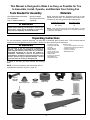
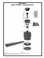
The Zonix
™
Ceiling Fan
Net Weight 9.07 kg (20 lbs)
Model No. FP4620**
OWNER’S MANUAL
READ AND SAVE THESE INSTRUCTIONS
Important Safety Instructions
WARNING: To avoid fire, shock and serious personal injury, follow these instructions.
1. Read your owner’s manual and safety information before installing your new fan. Review the accompanying assembly diagrams.
2. Before servicing or cleaning unit, switch power off at service panel and lock service panel disconnecting means to prevent power
from being switched on accidentally. When the service disconnecting means cannot be locked, securely fasten a warning device, such
as a tag, to the service panel.
3. Be careful of the fan and blades when cleaning, painting, or working near the fan. Always turn off the power to the ceiling fan before
servicing.
4. Do not insert anything into the fan blades while the fan is operating.
5. Do not operate reversing switch until fan blades have come to a complete stop.
Additional Safety Instructions
1. To avoid possible shock, be sure electricity is turned off at the fuse box before wiring, and do not operate fan without blades.
2. All wiring and installation procedures must satisfy National Electrical Codes (ANSI/ NFPA 70-1999) and Local Codes. The ceiling fan
must be grounded as a precaution against possible electrical shock. Electrical installation should be made or approved by a licensed
electrician.
3. The fan base must be securely mounted and capable of reliably supporting at least 50 lbs. See page 4 of owner’s manual for
support requirements. Consult a qualified electrician if in doubt.
4. The fan must be mounted with the fan blades at least 7 feet from the floor to prevent accidental contact with the fan blades.
5. Follow the recommended instructions for the proper method of wiring your ceiling fan. If you do not have adequate electrical
knowledge or experience, have your fan installed by licensed electrician.
WARNING: This product is designed to use only those parts supplied with this product and/or accessories designated specifically for
use with this product. Using parts and/or accessories not designated for use with this product could result in personal injury or property
damage.
WARNING: To reduce the risk of personal injury, do not bend the blade bracket (flange or blade holder) when installing the brackets,
balancing the blades, or cleaning the fan. Do not insert foreign objects in between rotating fan blades.
WARNING: To Reduce The Risk Of Fire Or Electric Shock. Do Not Use This Fan With Any Solid-State Speed Control Device.
LIMITED LIFETIME WARRANTY
Extends to the original purchaser of a Fanimation Fan
1. LIMITED LIFETIME MOTOR WARRANTY - If any part of your fan motor fails, due to a defect in materials or workmanship during
the lifetime of the original purchaser, Fanimation will provide the replacement part free of charge, when the defective fan is returned
to our national service center. Proof of purchase is required. Customer shall be responsible for all costs incurred in the removal or
reinstallation and shipping of the product for repairs or replacement.
2. ONE YEAR MOTOR LABOR WARRANTY - If your fan motor fails at any time within one year from the original purchase, due to
defects in materials or workmanship, labor to repair the motor will be provided free of charge at our national service center. Purchaser
will be responsible for labor charges after this one-year period. Customer shall be responsible for all costs incurred in the removal or
reinstallation and shipping of the product for repairs or replacement.
3. If any other part of your fan fails at any time within one year after original purchase, due to a defect in materials or workmanship, we
will repair, or replace, at our option, the defective part free of charge for parts and labor performed at our national service center.
4. Because of varying climate conditions, this warranty does not cover changes in the finish, including rusting, pitting, corroding,
tarnishing, or peeling.
5. This warranty is void and does not apply to damage from improper installation, neglect, accident, misuse, exposure to extremes of
heat or humidity, or as a result of any modification to the original product.
6. All costs of removal and reinstallation of the fan are the sole responsibility of the owner of the fan and not the store that sold the fan
or Fanimation.
7. Fanimation reserves the right to modify or discontinue any product at any time and may substitute any part under this warranty.
8. Under no circumstances may a fan be returned without prior authorization from Fanimation. The receipt of purchase must accompany authorized returns and must be sent freight prepaid to Fanimation. The fan to be returned must be properly packed to avoid
damage in transit; Fanimation will not be responsible for any damage resulting from improper packaging.
9. It is understood that any repair or replacement is the exclusive remedy available from Fanimation. There is no other expressed or
implied warranty. Fanimation hereby disclaims any and all implied warranties, including, but not limited to those of merchantability and
fitness for a particular purpose to the extent permitted by law. Some states do not allow limitations on implied warranties. Fanimation
will not be liable for incidental, consequential, or special damages arising out of or in conjunction with product use or performance,
except as may otherwise be accorded by law. This warranty gives you special legal rights and you may also have other rights that vary
from state to state.
10. A certain amount of wobble is normal and should not be considered a problem or a defect.
Table of Contents
Unpacking Instructions . . . . . . . . . . . . . . . . . . . . . . . . . . . . . . . . . . . . . . . 3
Energy Efficient Use of Ceiling Fans . . . . . . . . . . . . . . . . . . . . . . . . . . . . 4
Electrical and Structural Requirements . . . . . . . . . . . . . . . . . . . . . . . . . . 4
How to Assemble Your Ceiling Fan . . . . . . . . . . . . . . . . . . . . . . . . . . . . . 5
How to Hang Your Ceiling Fan . . . . . . . . . . . . . . . . . . . . . . . . . . . . . . . . . 6
How to Wire Your Ceiling Fan - CW40 Wall Control . . . . . . . . . . . . . . . . 7
Installing the Canopy Housing . . . . . . . . . . . . . . . . . . . . . . . . . . . . . . . . . 7
Mounting the Fan Blades and Lower Housing Cover . . . . . . . . . . . . . . . 8
Operating Instructions - CW40 Wall Control . . . . . . . . . . . . . . . . . . . . . . 9
Maintenance . . . . . . . . . . . . . . . . . . . . . . . . . . . . . . . . . . . . . . . . . . . . . . . . 9
Blade Cleaning . . . . . . . . . . . . . . . . . . . . . . . . . . . . . . . . . . . . . . . . . . . . . . 9
Parts List . . . . . . . . . . . . . . . . . . . . . . . . . . . . . . . . . . . . . . . . . . . . . . . . . . 10
Exploded-View Illustration. . . . . . . . . . . . . . . . . . . . . . . . . . . . . . . . . . . . 11
Trouble Shooting . . . . . . . . . . . . . . . . . . . . . . . . . . . . . . . . . . . . . . . . . . . 12
This Manual is Designed to Make it as Easy as Possible for You
to Assemble, Install, Operate, and Maintain Your Ceiling Fan
Tools Needed for Assembly
• One Phillips head screwdriver
• One stepladder
• One ¼˝ blade screwdriver
Materials
• One wire stripper
• Three wire connectors
(supplied)
Wiring outlet box and box connectors must be of type
required by local code. The minimum wire would be a 3conductor (2-wire with ground) of the following size:
▲WARNING
Before assembling your ceiling fan, refer to section on
proper method of wiring your fan (page 4). If you feel you
do not have enough wiring knowledge or experience,
have your fan installed by a licensed electrician.
Installed Wire Length
Wire Size A.W.G.
Up to 50 ft.
50 - 100 ft.
14
12
NOTE: Place the parts from the loose parts bags in a small
container to keep them from being lost. If any parts are missing,
contact your local retailer.
Unpacking Instructions
For your convenience, check-off each step. As each step is completed, place a check mark. This will ensure that all
steps have been completed and will be helpful in finding your place should you be interrupted.
• Fan Motor Assembly
• Downrod/Hanger Ball
Assembly
• Hanger Bracket
• Ceiling Canopy
• Canopy Screw Cover
• Motor Coupling Cover
• Adapter Plate
• Lower Cover Assembly
• Wood Blades (3)
• CW40 Wall Control
▲WARNING
Do not install or use fan if any part is damaged or
missing. This product is designed to use only those
parts supplied with this product and/or any accessories
designated specifically for use with this product by
Fanimation. Substitution of parts or accessories not
designated for use with this product by Fanimation could
result in personal injury or property damage. Contact
your retail store for missing or damaged parts.
• Hardware bags:
– 3/16-24 x 15 mm (blade to motor hub)
washer-head screws & fiber washers
– Phillips screwdriver, 4˝
– Four wire connectors
– Blade Balance Kit
1. Check to see that you have received the following
parts:
NOTE: If you are uncertain of part description, refer to
exploded view illustration. (Figure 1, page 13)
Downrod/
Hanger Ball
Assembly
Motor Coupling Cover
Canopy
Screw Cover
Ceiling Canopy
Hanger Bracket
Lower Cover Assembly
Adapter Plate
Blade Set
Fan Motor Assembly
3
Hardware Bags
CW40 Wall Control
Energy Efficient Use of Ceiling Fans
Ceiling fan performance and energy savings rely
heavily on the proper installation and use of the ceiling
fan. Here are a few tips to ensure efficient product
performance.
Using the Ceiling Fan Year Round
Summer Season: Use the ceiling fan in the counterclockwise direction. The airflow produced by the ceiling
fan creates a wind-chill effect, making you “feel” cooler.
Select a fan speed that provides a comfortable breeze,
lower speeds consume less energy.
Winter Season: Reverse the motor and operate the ceiling
fan at low speed in the clockwise direction. This produces
a gentle updraft, which forces warm air near the ceiling
down into the occupied space.Remember to adjust your
thermostat when using your ceiling fan - additional energy
and dollar savings could be realized with this simple step!
Choosing the Appropriate Mounting Location
Ceiling fans should be installed, or mounted, in the middle
of the room and at least 7 feet above the floor and 18
inches from the walls. If ceiling height allows, install the fan
8 - 9 feet above the floor for optimal airflow. Consult your
Fanimation Retailer for optional mounting accessories.
Turn Off When Not in the Room
Ceiling fans cool people, not rooms. If the room is
unoccupied, turn off the ceiling fan to save energy.
Electrical and Structural Requirements
Your new ceiling fan will require a grounded electrical
supply line of 120 volts AC, 60 Hz, 15 amp circuit. The
outlet box must be securely anchored and capable of
withstanding a load of at least 50 lbs. Figure 1 depicts
different structural configurations that may be used for
mounting the outlet box.
Ceiling
▲WARNING
Ceiling
Joists
To reduce the risk of fire, electrical shock, or personal
injury, mount fan to outlet box marked acceptable for
fan support. Use screws supplied with outlet box. Most
outlet boxes commonly used for support of light fixtures
are not acceptable for fan support and may need to be
replaced. Consult a qualified electrician if in doubt.
2˝ x 4˝
Outlet
Box
▲WARNING
Figure 1
Turning off wall switch is not sufficient. To avoid
possible electrical shock, be sure electricity is turned
off at the main fuse box before wiring. All wiring must
be in accordance with National and Local codes and the
ceiling fan must be properly grounded as a precaution
against possible electrical shock.
▲WARNING
To avoid fire or shock, follow all wiring instructions
carefully. Any electrical work not described in these
instructions should be done or approved by a licensed
electrician.
4
How to Assemble Your Ceiling Fan
1. Remove the Hanger Ball by loosening the setscrew
in the Hanger Ball until the ball falls freely down the
Downrod. (Figure 1) Remove the Pin from the Downrod,
then remove the Hanger Ball. Retain the Pin and Hanger
Ball for reinstallation in Step 5.
Pin
Hanger
Ball
2. The fan comes with blue, black and white 80˝ wires.
Separate & untwist the three wires and safety cable. Route
the wires through the downrod.
Setscrew
NOTE: You will be using either the 6˝ downrod supplied with
your fan or an optional downrod purchased separately.
3. Loosen the two setscrews in the Downrod Support. Align
the Clevis Pin holes in the Downrod with the holes in the
Downrod Support. Install the Clevis Pin and secure with
the Hairpin Clip. (Figure 3) Be sure to push the straight
leg of the hairpin clip through the hole near the end of the
clevis pin until the curved portion of the hairpin clip snaps
around the clevis pin. The hairpin clip must be properly
installed to prevent the clevis pin from working loose. Pull
on the Downrod to make sure the clevis pin is properly
installed.
Figure 1
Motor
Coupling
Cover
Downrod
Support
▲WARNING
Clevis Pin
It is critical that the clevis pin in the downrod support
is properly installed and the setscrews are securely
tightened. Failure to verify that the pin and setscrews
are properly installed could result in the fan falling.
Setscrew (2)
Hairpin Clip
Reverse
Switch
4. Route wires through Motor Coupling Cover, Canopy
(with Canopy Screw Cover) on fan shown with open side
facing up. (Figure 3)
Figure 2
5. Reinstall the Hanger Ball (Figure 1) on the Downrod
as follows. Route the three 80˝ wires and cable through
the Hanger Ball. Position the Pin through the two holes
in the Downrod and align the Hanger Ball so the Pin is
captured in the groove in the top of the Hanger Ball. Pull
the Hanger Ball up tight against the pin. Securely tighten
the setscrew in the Hanger Ball. A loose setscrew
could create fan wobble.
6. While pulling up on the hanger ball, securely tighten the
two setscrews with nuts in the downrod support. Slide the
Motor Coupling Cover down on top of the motor housing.
(Figures 2 & 3)
7. Before installing fan, measure up approximately 6-9
inches above top of Downrod/Hanger Ball Assembly. Cut
off excess wire and strip back insulation ½˝ from end of
wire.
8. All set screws must be checked and retightened where
necessary before installation.
9. You have now completed the upper assembly of your
new ceiling fan. You can now proceed with the hanging
and the electrical wiring of your fan.
Figure 3
5
How to Hang Your Ceiling Fan
▲WARNING
To avoid possible electrical shock, be sure electricity is
turned off at the main fuse box before hanging.
NOTE: If you are not sure if the outlet box is grounded,
contact a licensed electrician for advice, as it must be
grounded for safe operation.
▲WARNING
The fan must be hung with at least 7´ of clearance from
floor to blades (Figure 1)
No
less than
7 ft
▲WARNING
Floor
The outlet box must be securely anchored and capable
of withstanding a load of at least 50 lbs. Hanger bracket
must seat firmly against outlet box. If the outlet box is
recessed, remove wallboard until bracket contacts box.
If bracket and/or outlet box are not securely attached,
the fan could wobble or fall.
Figure 1
Outlet Box
CAUTION
Hanger
Bracket
Do not connect fan blades until the fan is completely
installed. Hanging fan with blades connected may result
in damage to the fan blades.
1. Securely attach the hanger bracket to the outlet box
using the outlet box screws and washers supplied with the
outlet box (Figure 2).
NOTE: Outlet box screws pass through slotted holes of
the hanger bracket (Figure 2).
Tab
Screw (2)
Supplied with
Outlet Box
2. Pull the electric wires in the outlet box down through
the opening in the hanger bracket and bend wires up and
out of the way so that the hanger ball will easily fit into the
hanger bracket.
Figure 2
Outlet Box
3. Carefully lift the fan and seat the downrod/hanger ball
assembly on the hanger bracket that was just attached to
the outlet box (Figure 3). Be sure the groove in the ball is
lined up with tab on the hanger bracket (Figure 2).
Hanger
Bracket
4. After splicing, the wiring should be turned upward and
pushed carefully up into the outlet box.
▲WARNING
Downrod/Hanger
Ball Assembly
Failure to seat tab in groove could cause damage to
electrical wires and possible shock or fire hazard.
Figure 3
▲WARNING
To avoid possible shock, do not pinch wires between the
downrod/hanger ball assembly and the hanger bracket.
6
How to Wire Your Ceiling Fan - CW40 Wall Control
If you feel that you do not have enough electrical wiring knowledge or experience, have your fan installed by a
licensed electrician.
▲WARNING
1. Installing Wall Control (Figures 1 & 2):
• With electrical power still disconnected, remove the
existing wall plate and switch.
• Make wiring connections with wire nuts as shown in
Figure 1.
– One black wire from wall control unit to black
(hot supply).
– One black wire from wall control unit to black wire
leading to ceiling outlet box.
– One green wire from wall control unit to ground wire
leading to ceiling outlet box.
• Attach wall control unit to outlet box using the two
6-32 screws provided.
• Attach wall plate to the switch control front using the two
small screws provided.
WH-TO MOTOR
BLU-TO LIGHT
BLK-TO MOTOR
BLK
TO HOT
GRN
WH
GRN from bracket
BLK TO FAN
GRN TO GROUND
GRN from hanger ball
To avoid possible electrical shock, be sure electricity is
turned off at the main fuse box before wiring.
NOTE: If you are not sure if the outlet box is grounded,
contact a licensed electrician for advice, as it must be
grounded for safe operation.
BLK
120 VAC SUPPLY
(User Supplied)
Figure 1
Hot Supply
Ground
Supply To Fan
NOTE: Blue wire MUST be capped if not installing optional light
kit.
▲WARNING
Check to see that all connections are tight, including
ground, and that no bare wire is visible at the wire
connectors, except for the ground wire. Do not operate
fan until the blades are in place. Noise and fan damage
could result.
Figure 2
Installing the Canopy Housing
NOTE: This step is applicable after the necessary wiring
is completed.
▲WARNING
To avoid possible fire or shock, make sure that the
electrical wires are completely inside the canopy housing
and not pinched between the housing and the ceiling.
1. Loosen the two shoulder screws in the Hanger
Bracket.
Figure 1a
2. Securely attach the Canopy Housing over the shoulder
screws (Figure 1a).
3. Securely attach and tighten the Canopy Screw Cover
over the shoulder screws in the Hanger Bracket utilizing
the keyslot twist-lock feature (Figure 1b).
7
Figure 1b
Mounting the Fan Blades and Switch Cup Cover Assembly
INSTALLATION NOTE
Do not connect fan blades until the fan is completely
installed. Installing the fan with blades assembled may
result in damage to the fan blades.
▲WARNING
Fan Blade
To reduce the risk of personal injury, do not bend the
blades when installing, balancing or cleaning the fan.
Do not insert foreign objects in between the rotating
blades.
Figure 1
Blade Assembly:
1. Carefully slide the blade through the slot as shown.
(Figure 1)
2. Securely fasten the three blades with washer-head
screws with fiber washers. Do not over-tighten.
(Figure 2)
Washer-Head
Screw with
Fiber Washer
(3 per blade)
Figure 2
Switch Cup Cover Assembly:
3. Disassemble Switch Cup Cover from Switch Cup
Support Plate by removing three screws. (Figure 3)
Figure 3
4. Loosen three screws and remove one screw from
support flange. (Figure 4)
Figure 4
5. Attach the Switch Cup Support Plate to the support
flange by rotating plate and properly positioning screws
in key slots. Install fourth screw in remaining hole. Fully
tighten all four screws. (Figure 5)
Figure 5
8
Mounting the Fan Blades and Switch Cup Cover Assembly (cont’d)
6. Assemble the Switch Cup Cover onto the assembled
Switch Cup Support Plate with three screws provided.
(Figure 6)
7. Restore Power and your fan is now wired to be turned
on and off from the wall speed control.
Screw (3)
Figure 6
Operating Instructions - CW40 Wall Control
1. Restore electrical power to the outlet box by turning the
electricity on at the main fuse box.
2. Your fan model is equipped with a 4-position, 3-speed,
slide switch wall control. The operating sequence is as
follows:
• 4th Position = low speed
• 3rd Position = medium speed
• 2nd Position = medium high speed
• 1st Position = high speed
• — Position = fan off
3. If airflow is desired in the opposite direction, turn the
fan off and wait for the blades to stop turning. Slide the
reverse switch to the opposite position (located on top of
fan housing) and turn fan on again.
Figure 1
Maintenance
Periodic cleaning of your new ceiling fan is the only
maintenance that is needed.
When cleaning, use only a soft brush or lint free cloth to
avoid scratching the finish.
Abrasive cleaning agents are not required and should be
avoided to prevent damage to finish.
CAUTION
Do not use water when cleaning your ceiling fan. It
could damage the motor or the blades and create the
possibility of electrical shock.
Blade Cleaning
Periodic light dusting of the blades is recommended.
A feather duster will work best.
Avoid using water, cleansers, or harsh rags, which can
warp and ruin the blades.
9
Parts List
Model FP4620**
Ref. #
Description
1
Hanger Bracket Assembly with Screws
2
Downrod/Hanger Ball Assembly Containing:
2a
Hanger Ball Assembly
2b
Downrod
Part #
AP255BL
ADR1-6**
2c
Clevis Pin
2d
Hairpin Clip
3
Ceiling Canopy
4
Canopy Screw Cover
AP260**
5
Motor Coupling Cover with Grommet
AP1115**
6
Fan Motor Assembly
AMA4620**
7
Switch Cup Cover Assembly with Flat-Head Screws (3)
AP462010**
8
Blade Set (3)
AP462007**
9
Wall Control
CW40
PG154**
Hardware Bag Containing:
HDWFP4620
Blade Balance Kit (BALKT)
HDWHW4620
Wire Connectors (4)
10
Blade Mounting Hardware Bag Containing:
3/16–24
x 15 mm Washer Head Screw (10)
Fiber Washers (10)
HDWBM4620
Phillips Screwdriver, 4˝
¾¾
Insert FINISH CODES (Refer to fan model number located on downrod support)
Before discarding packaging materials, be certain all parts have been removed
How To Order Parts
When ordering repair parts, always
give the following information:
• Part Number
• Part Description
• Fan Model Number
Contact your retail store for repair parts.
10
The Zonix™
Model FP4620** Exploded-View
1
2a
9
2b
2
2c
2d
3
4
5
6
8
7
Figure 1
NOTE: The illustration shown is not to scale or its actual configuration may vary.
Product/parts are subject to change without notice.
11
10
Trouble Shooting
▲WARNING
For your own safety turn off power at fuse box or circuit breaker before trouble shooting your fan.
Trouble
1. FAN WILL NOT START
Probable Cause
Suggested Remedy
1. Fuse or circuit breaker blown.
1. Check main and branch circuit fuses or circuit
breakers.
2. Loose power line connections to the fan, or loose
switch wire connections in the switch housing.
2. Check line wire connections to fan and switch wire
connections in the switch housings.
CAUTION: Make sure main power is turned off !
3. Reversing switch in neutral position.
3. Make sure reversing switch position is all the way to
one side.
1. Blades not attached to fan.
1. Attach blades to fan before operating.
2. Loose screws in motor housing.
2. Check to make sure all screws in motor housing are
snug (not over-tight).
3. Screws securing fan blade holders to motor flywheel
are loose.
3. Check to make sure the screws which attach the fan
blade holders to the motor flywheel are tight.
4. Wire connectors inside housing rattling.
4. Check to make sure wire connectors in switch
housing are not rattling against each other or against
the interior wall of the switch housing.
2. FAN SOUNDS NOISY
CAUTION: Make sure main power is turned off !
5. Motor noise caused by solid state variable speed
control.
5. Some fan motors are sensitive to signals from
solid-state variable speed controls. Solid-state controls
are not recommended, choose an alternative control
method.
6. Lock nuts holding blades to blade holders are loose.
6. Tighten lock nuts securely.
7. Lower housing support set screw loose.
7. Tighten set screw securely.
1. Setscrew in downrod support is loose.
1. Tighten both setscrews securely in downrod support.
2. Setscrew in downrod/hanger ball assembly is loose.
2. Tighten the setscrew in the downrod/hanger ball
assembly.
3. Screws securing fan blade holders to motor hub are
loose.
3. Check to be sure screws which attach the fan blade
holders to the flywheel are tight.
4. Blade holders not seated properly.
4. Check to be sure the fan blade holders seat firmly
and uniformly to the surface of the motor housing. If
holders are seated incorrectly, loosen the screws and
retighten.
5. Hanger bracket and/or ceiling outlet box is not
securely fastened.
5. Tighten the hanger bracket screws to the outlet box,
and secure outlet box.
6. Fan blades out of balance.
6. Interchanging position of fan blades can redistribute
the weight and result in a smoother operation. For
example, exchange blades in positions 1 and 3 or 1 and
4. If this does not improve wobble, exchange 2 and 3 or
2 and 4.
3. FAN WOBBLES
EXCESSIVELY
1. If possible, consider using a longer downrod. For
example, use a 12” downrod instead of the 6” downrod
that comes with your fan.
4. NOT ENOUGH AIR
MOVEMENT
12
Copyright 2008 Fanimation
10983 Bennett Parkway
Zionsville, IN 46077
(888) 567-2055
FAX (866) 482-5215
Outside U.S. call (317) 733-4113
Visit Our Website @ www.fanimation.com
2008/02