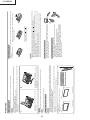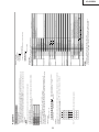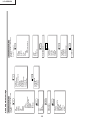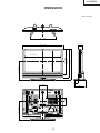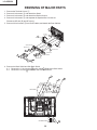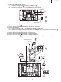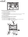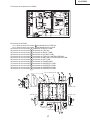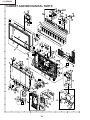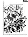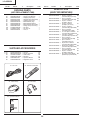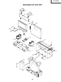
1
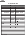
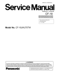
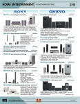
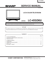
LC-45GD6U SERVICE MANUAL SY4B6LC45GD6U LCD COLOR TELEVISION MODEL LC-45GD6U In the interests of user-safety (Required by safety regulations in some countries) the set should be restored to its original condition and only parts identical to those specified should be used. OUTLINE This model is based on the LC-45GD4U and is equipped with a redesigned speaker. This Service Manual covers the modifications alone. For the other points, refer to the LC-45GD4U Service Manual. CONTENTS Page » » » » » » » » LIST OF CHANGED PARTS ...........................................................................................................................2 IMPORTANT SERVICE SAFETY PRECAUTION ........................................................................................ 3 SPECIFICATIONS........................................................................................................................................6 OPERATION MANUAL ................................................................................................................................7 DIMENSIONS ............................................................................................................................................13 REMOVING OF MAJOR PARTS ................................................................................................................14 PARTS LIST ...............................................................................................................................................20 PACKING OF THE SET .............................................................................................................................27 SHARP CORPORATION This document has been published to be used for after sales service only. The contents are subject to change without notice. LC-45GD6U LIST OF CHANGED PARTS Ref.No. Description LC-45GD4U LC-45GD6U Note PWB ASSEMBLIES HDMI/DVI Unit DUNTKC267VJ59 DUNTKC267VJ60 No parts changed DIGITAL Unit DKEYDC307VJ37 DKEYDC307VJ38 No parts changed INVERTER-1 Unit DUNTKC471UJ05 DUNTKC471UJ06 No parts changed INVERTER-2 Unit DUNTKC472UJ05 DUNTKC472UJ06 No parts changed INVERTER-3 Unit DUNTKC473UJ05 DUNTKC473UJ06 No parts changed INVERTER-4 Unit DUNTKC474UJ05 DUNTKC474UJ06 No parts changed PC CARD Unit DUNTKC544VJ06 TOP LCD CONTROLLER Unit DUNTKD001UJ01 DUNTKD001UJ02 Parts changed BOTTOM LCD CONTROLLER Unit DUNTKD002UJ01 DUNTKD002UJ02 No parts changed MAIN Unit DUNTKD003VJ01 DUNTKD003VJ02 No parts changed DC/DC1 Unit DUNTKD004VJ01 DUNTKD004VJ02 No parts changed DC/DC2 Unit DUNTKD005UJ01 DUNTKD005UJ02 No parts changed AV Unit DUNTKD006VJ01 DUNTKD006VJ02 No parts changed AV SUB Unit DUNTKD007UJ01 DUNTKD007UJ02 No parts changed SP-T Unit DUNTKD008UJ01 DUNTKD008UJ02 Parts changed AC-INLET Unit DUNTKD009UJ01 DUNTKD009UJ02 No parts changed KEY_U Unit DUNTKD010UJ01 DUNTKD010UJ02 No parts changed R/C, LED Unit DUNTKD011UJ01 DUNTKD011UJ02 No parts changed POWER Unit RDENCA085WJZZ 1BIT AMP Unit B2SX4102BT 45” Wide LCD Panel Unit RLCDTA030WJZZ LCD PANEL TOP LCD CONTROLLER Unit R2209 Metal Oxide R2215 Metal Oxide VRS-CY1JF223JY VRS-CY1JF103JY VRS-CY1JF223JY QTANAA004WJZZ SP-T Unit J203 Terminal, 4Pin QTANAA003WJZZ CABINET AND MECHANICAL PARTS Please refer to a Parts list. PACKING PARTS AND ACCESSORIES Please refer to a Parts list. 2 LC-45GD6U IMPORTANT SERVICE SAFETY PRECAUTION Ë Service work should be performed only by qualified service technicians who are thoroughly familiar with all safety checks and the servicing guidelines which follow: » Use an AC voltmeter having with 5000 ohm per volt, or higher, sensitivity or measure the AC voltage drop across the resistor. » Connect the resistor connection to all exposed metal parts having a return to the chassis (antenna, metal cabinet, screw heads, knobs and control shafts, escutcheon, etc.) and measure the AC voltage drop across the resistor. All checks must be repeated with the AC cord plug connection reversed. (If necessary, a nonpolarized adaptor plug must be used only for the purpose of completing these checks.) Any reading of 0.75 Vrms (this corresponds to 0.5 mA rms AC.) or more is excessive and indicates a potential shock hazard which must be corrected before returning the monitor to the owner. WARNING 1. For continued safety, no modification of any circuit should be attempted. 2. Disconnect AC power before servicing. A V CAUTION: FOR CONTINUED PROTECTION AGAINST A RISK OF FIRE REPLACE ONLY WITH SAME TYPE FUSE. F7003 (2A, 250V), F7004 (1A, DC 450V) F7301, F7302, F7401, F7402, F7501, F7502, F7601, F7602 (4A,250V) F7801 (8A, 250V) BEFORE RETURNING THE RECEIVER (Fire & Shock Hazard) Before returning the receiver to the user, perform the following safety checks: DVM AC SCALE 1. Inspect all lead dress to make certain that leads are not pinched, and check that hardware is not lodged between the chassis and other metal parts in the receiver. 2. Inspect all protective devices such as non-metallic control knobs, insulation materials, cabinet backs, adjustment and compartment covers or shields, isolation resistor-capacitor networks, mechanical insulators, etc. 3. To be sure that no shock hazard exists, check for leakage current in the following manner. » Plug the AC cord directly into a 120 volt AC outlet. » Using two clip leads, connect a 1.5k ohm, 10 watt resistor paralleled by a 0.15µF capacitor in series with all exposed metal cabinet parts and a known earth ground, such as electrical conduit or electrical ground connected to an earth ground. 1.5k ohm 10W 0.15 µF TEST PROBE TO EXPOSED METAL PARTS CONNECT TO KNOWN EARTH GROUND 12345678901234567890123456789012123456789012345678901234567890121234567890123456789012345678901212 12345678901234567890123456789012123456789012345678901234567890121234567890123456789012345678901212 12345678901234567890123456789012123456789012345678901234567890121234567890123456789012345678901212 12345678901234567890123456789012123456789012345678901234567890121234567890123456789012345678901212 SAFETY NOTICE and shaded areas in the Replacement Parts List and Schematic Diagrams. For continued protection, replacement parts must be identical to those used in the original circuit. The use of a substitute replacement parts which do not have the same safety characteristics as the factory recommended replacement parts shown in this service manual, may create shock, fire or other hazards. Many electrical and mechanical parts in LCD color television have special safety-related characteristics. These characteristics are often not evident from visual inspection, nor can protection afforded by them be necessarily increased by using replacement components rated for higher voltage, wattage, etc. Replacement parts which have these special safety characteristics are identified in this manual; electrical components having such features are identified by " å" 12345678901234567890123456789012123456789012345678901234567890121234567890123456789012345678901212 12345678901234567890123456789012123456789012345678901234567890121234567890123456789012345678901212 12345678901234567890123456789012123456789012345678901234567890121234567890123456789012345678901212 12345678901234567890123456789012123456789012345678901234567890121234567890123456789012345678901212 3 LC-45GD6U PRECAUTIONS A PRENDRE LORS DE LA REPARATION Ë Ne peut effectuer la réparation qu' un technicien spécialisé qui s'est parfaitement accoutumé à toute vérification de sécurité et aux conseils suivants. de 0.15µF en série avec toutes les pièces métalliques exposées du coffret et une terre connue comme une conduite électrique ou une prise de terre branchée à la terre. • Utiliser un voltmètre CA d'une sensibilité d'au moins 5000Ω/V pour mesurer la chute de tension en travers de la résistance. • Toucher avec la sonde d'essai les pièces métalliques exposées qui présentent une voie de retour au châssis (antenne, coffret métallique, tête des vis, arbres de commande et des boutons, écusson, etc.) et mesurer la chute de tension CA en-travers de la résistance. Toutes les vérifications doivent être refaites après avoir inversé la fiche du cordon d'alimentation. (Si nécessaire, une prise d'adpatation non polarisée peut être utilisée dans le but de terminer ces vérifications.) Tous les courants mesurés ne doivent pas dépasser 0.5 mA. Dans le cas contraire, il y a une possibilité de choc électrique qui doit être supprimée avant de rendre le récepteur au client. AVERTISSEMENT 1. N'entreprendre aucune modification de tout circuit. C'est dangereux. 2. Débrancher le récepteur avant toute réparation. A V P R E C AU T I O N : P O U R L A PROTECTION CONTINUE CONTRE LES RISQUES D'INCENDIE, REMPLACER LE FUSIBLE F7003 (2A, 250V), F7004 (1A, DC 450V) F7301, F7302, F7401, F7402, F7501, F7502, F7601, F7602 (4A,250V) F7801 (8A, 250V) VERIFICATIONS CONTRE L'INCEN-DIE ET LE CHOC ELECTRIQUE Avant de rendre le récepteur à l'utilisateur, effectuer les vérifications suivantes. 1. Inspecter tous les faisceaux de câbles pour s'assurer que les fils ne soient pas pincés ou qu'un outil ne soit pas placé entre le châssis et les autres pièces métalliques du récepteur. 2. Inspecter tous les dispositifs de protection comme les boutons de commande non-métalliques, les isolants, le dos du coffret, les couvercles ou blindages de réglage et de compartiment, les réseaux de résistancecapacité, les isolateurs mécaniques, etc. 3. S'assurer qu'il n'y ait pas de danger d'électrocution en vérifiant la fuite de courant, de la facon suivante: • Brancher le cordon d'alimentation directem-ent à une prise de courant de 120V. (Ne pas utiliser de transformateur d'isolation pour cet essai). • A l'aide de deux fils à pinces, brancher une résistance de 1.5 kΩ 10 watts en parallèle avec un condensateur DVM ECHELLE CA 1.5k ohm 10W 0.15 µF SONDE D'ESSAI AUX PIECES METALLIQUES EXPOSEES BRANCHER A UNE TERRE CONNUE 12345678901234567890123456789012123456789012345678901234567890121234567890123456789012345678901212 12345678901234567890123456789012123456789012345678901234567890121234567890123456789012345678901212 12345678901234567890123456789012123456789012345678901234567890121234567890123456789012345678901212 AVIS POUR LA SECURITE identifiées par la marque " å " et hachurées dans la De nombreuses pièces, électriques et mécaniques, dans liste des pièces de remplacement et les diagrammes les téléviseur ACL présentent des caractéristiques schématiques. spéciales relatives à la sécurité, qui ne sont souvent Pour assurer la protection, ces pièces doivent être pas évidentes à vue. Le degré de protection ne peut identiques à celles utilisées dans le circuit d'origine. pas être nécessairement augmentée en utilisant des L'utilisation de pièces qui n'ont pas les mêmes pièces de remplacement étalonnées pour haute tension, caractéristiques que les pièces recommandées par puissance, etc. l'usine, indiquées dans ce manuel, peut provoquer des Les pièces de remplacement qui présentent ces électrocutions, incendies, radiations X ou autres caractéristiques sont identifiées dans ce manuel; les accidents. pièces électriques qui présentent ces particularités sont 12345678901234567890123456789012123456789012345678901234567890121234567890123456789012345678901212 12345678901234567890123456789012123456789012345678901234567890121234567890123456789012345678901212 12345678901234567890123456789012123456789012345678901234567890121234567890123456789012345678901212 12345678901234567890123456789012123456789012345678901234567890121234567890123456789012345678901212 4 LC-45GD6U Precautions for using lead-free solder 1 Employing lead-free solder "PWBs" of this model employs lead-free solder. The LF symbol indicates lead-free solder, and is attached on the PWBs and service manuals. The alphabetical character following LF shows the type of lead-free solder. Example: LFa Indicates lead-free solder of tin, silver and copper. 2 Using lead-free wire solder When fixing the PWB soldered with the lead-free solder, apply lead-free wire solder. Repairing with conventional lead wire solder may cause damage or accident due to cracks. As the melting point of lead-free solder (Sn-Ag-Cu) is higher than the lead wire solder by 40°C, we recommend you to use a dedicated soldering bit, if you are not familiar with how to obtain lead-free wire solder or soldering bit, contact our service station or service branch in your area. 3 Soldering As the melting point of lead-free solder (Sn-Ag-Cu) is about 220°C which is higher than the conventional lead solder by 40°C, and as it has poor solder wettability, you may be apt to keep the soldering bit in contact with the PWB for extended period of time. However, since the land may be peeled off or the maximum heat-resistance temperature of parts may be exceeded, remove the bit from the PWB as soon as you confirm the steady soldering condition. Lead-free solder contains more tin, and the end of the soldering bit may be easily corroded. Make sure to turn on and off the power of the bit as required. If a different type of solder stays on the tip of the soldering bit, it is alloyed with lead-free solder. Clean the bit after every use of it. When the tip of the soldering bit is blackened during use, file it with steel wool or fine sandpaper. Be careful when replacing parts with polarity indication on the PWB silk. Lead-free wire solder for servicing Part No, ★ Description ZHNDAi123250E J φ0.3mm 250g(1roll) ZHNDAi126500E J φ0.6mm 500g(1roll) ZHNDAi12801KE J φ1.0mm 1kg(1roll) 5 Code BL BK BM LC-45GD6U SPECIFICATIONS Item 45" LIQUID CRYSTAL TELEVISION, Model: LC-45GD6U LCD panel Number of dots TV TV-standard (CCIR) Function Receiving VHF/UHF Channel CATV Digital Terrestrial Broadcast (8VSB) Digital cable (64/256 QAM) Audio multiplex Brightness Viewing angles Audio amplifier Speakers Terminals Rear INPUT 1 45" Advanced Super View & BLACK TFT LCD 6,220,800 dots (1920 × 1080 × 3 dots) American TV Standard ATSC/NTSC System VHF 2-13ch, UHF 14-69ch 1-125ch 2-69ch 1-135ch BTSC System 450 cd/m2 H : 170° V : 170° 10W × 2 Ø 8cm 2pcs, Ø 2.5cm 2pcs AV in, COMPONENT in AV in, COMPONENT in S-VIDEO in, AV in INPUT 3 HDMI in (Type-A) with HDCP INPUT 4 INPUT 5 Audio in, DVI-I in with HDCP ANALOG ANTENNA 75 Ω Unbalance, F Type for VHF/UHF/CATV in × 2, out × 1 DIGITAL ANTENNA 75 Ω Unbalance, F Type for Digital Air/Cable in × 1 MONITOR OUTPUT S-VIDEO out, AV out 4 Ω 10W (L/R) EXTERNAL SPEAKER INPUT 2 CENTER CHANNEL INPUT RCA pin DIGITAL AUDIO OUTPUT i.LINK PC CARD slot CableCARD slot DC OUTPUT Optical Digital audio output × 1 (PCM/Dolby Digital) IEEE1394 × 2 with DTCP 68 pin PCMCIA × 1 68 pin PCMCIA × 1 DC 9 V 7 W MAX English/French/Spanish OSD language Power Requirement Power Consumption Display only Weight AC 120 V, 60 Hz 330 W (13.4 W Standby with AC 120 V) 60.6 lbs./27.5 kg with Display and speaker 71.7 lbs./32.5 kg with Display, speaker and stand 80.5 lbs./36.5 kg • As part of policy of continuous improvement, SHARP reserves the right to make design and specification changes for product improvement without prior notice. The performance specification figures indicated are nominal values of production units. There may be some deviations from these values in individual units. 6 Display INPUT button POWER button 7 OPC indicator OPC sensor POWER indicator CARD indicator CHANNEL buttons (CH / ) VOLUME buttons (VOL / ) Remote control sensor Part names * OPC: Optical Picture Control RS-232C terminal CENTER CHANNEL INPUT terminal RESET* AV MODE resets to DYNAMIC (Fixed) TV channel returns to initial channel (Air:2ch, Cable:1 or 2ch) Twin picture resets to normal Audio setting initializes Dolby virtual resets to off Image position initializes • Pressing RESET will not work if the TV is in standby mode. • Pressing RESET will not delete channel preset or secret number. NOTE INPUT 5 terminals AC INPUT terminal i.LINK terminals INPUT 4 terminal CableCARD slot ANALOG B IN terminal ANALOG A OUT terminal ANALOG A IN terminal ** Press SYSTEM RESET if the TV does not operate after starting up. • • • • • • * Press RESET if the TV cannot return to its original state after performing various operations. DIGITAL IN terminal SYSTEM RESET** EXTERNAL SPEAKER terminals INPUT 2 terminals MONITOR OUTPUT terminals DC OUTPUT terminal (Terminal for expanded functionality in the near future.) DIGITAL AUDIO OUTPUT terminal INPUT 1 terminals INPUT 3 terminals Display Part names LC-45GD6U OPERATION MANUAL 8 33 32 28 29 30 31 • When using the remote control unit, point it at the Liquid Crystal Television. 12 13 14 15 16 11 27 24 25 26 7 8 9 10 20 19 18 21 22 23 17 6 5 4 2 3 1 1 Virtual: Selects Virtual Dolby Surround settings. 32 EDIT: Registers favorite channel. 33 AV MODE: Selects an audio or video setting. (AV mode: STANDARD, MOVIE, GAME, USER, DYNAMIC (Fixed), DYNAMIC. PC mode: STANDARD, USER.) While watching, you can toggle the selected channels by pressing A, B, C and D. 30 FREEZE: Sets the still image. Press again to return to normal screen. 31 CC: Displays captions during closed-caption source. 20 FLASHBACK: Returns to the previous channel or input external mode. 21 INPUT: Selects a Liquid Crystal Television input source. (TV, INPUT 1, INPUT 2, INPUT 3, INPUT 4, INPUT 5, i.LINK, Card) 22 DIGITAL: Receives digital broadcasts. 23 CH / : Selects the channel. 24 MUTE: Mutes the sound. 25 CH LIST: Displays the channel list screen. 26 MENU: Displays the menu screen. 27 / / / /ENTER: Selects a desired item on the screen. 28 RETURN: Returns to the previous menu screen. 29 FAVORITE CH A, B, C, D: Selects four preset favorite channels in four different categories. 14 SLEEP: Sets the sleep timer. 15 AUDIO: Selects the MTS/SAP or the audio mode during multi-channel audio broadcasts. 16 i.LINK: Displays the i.LINK panel. 17 FUNCTION: Switches the remote control for TV, CBL/ SAT, VCR, DVD and AUDIO operation. Indicator lights up for the current mode. 18 : When pressed all buttons on the remote control unit will light. The lighting will turn off if no operations are performed within about 5 seconds. This button is used for performing operations in low-light situations. 19 VIEW MODE: Selects the screen size. 11 EXIT: Turns off the menu screen. 12 SELECT: Selects the active screen. 13 TWIN PICTURE: Sets the twin picture mode. Press again to return to normal screen. 10 7 8 9 5 6 4 TV POWER: Switches the Liquid Crystal Television power on or Standby. DISPLAY: Displays the channel information. SOURCE POWER: Turns the power of the external equipment on and off. External equipment operational buttons: Operates the external equipment. 0 – 9: Sets the channel. A-ANALOG-B: Each button selects the corresponding antenna. VOL / : Sets the volume. CARD: Switches to card mode. INFO: Displays the program information screen. 2 1 4 inches (10 cm) or more • Do not remove the stand and speaker from the Display unless using an optional bracket to mount it. • Keep enough space above and behind the Display. • When you move the TV, carry it by two or more people. • When you move the Display, hold the side portion of the Display, not the speaker. CAUTION Handling the Display Setting the TV in place Display • Select a place with good ventilation. Selecting the location of the TV First select the location where to place the TV. Where to place the TV Remote control unit 2 3 Preparation Part names CAUTION Adjust the screen with both hands. Put one hand on the Display and rotate the screen while steadying the stand with your other hand. Please note that you cannot adjust the screen vertically with this model. LC-45GD6U 9 AC cord (with Ferrite core) Press down the hooks to remove the cover toward you. Insert the cable clamp in the hole on the Display as shown. Cable clamp Bundling the cables with the clamp Connecting the AC cord to the Display Display (rear view) Removing the terminal cover • TO PREVENT RISK OF ELECTRIC SHOCK, DO NOT TOUCH UN-INSULATED PARTS OF ANY CABLES WITH THE AC CORD CONNECTED. CAUTION 3 2 1 After putting the Display in place, connect the AC cord. Use the cable clamp for bundling the cables. Setting the TV Preparation Unfasten the screws. 4 • To attach the speakers, perform the steps in reverse order. NOTE • Do not remove the stand and speaker from the Display unless using an optional bracket to mount it. • Before performing work spread cushioning over the base area to lay the Display on. This will prevent it from being damaged. CAUTION Disconnect the cable from the speaker. 3 Take off the speaker terminal cover. 2 Unfasten the screw used to secure the speaker bracket. 1 Removing speakers LC-45GD6U Detach the stand from the Display. (Hold the stand so it will not drop from the edge of the base area.) Unfasten the four screws used to secure the stand in place. 10 Vertical mounting Angular mounting Hanging on the wall AN-37AG2 wall mount bracket. (See the bracket instructions for details.) With Speakers Attached 5˚ With Speakers Removed 5˚ Angle of Display About setting the Display angle 5˚ Using an optional bracket to mount the Display • You can ask a qualified service personnel about using the optional AN-37AG2 bracket to mount the Display to the wall. • Carefully read the instructions that come with the bracket before beginning work. • Installing the Liquid Crystal Television requires special skill that should only be performed by qualified service personnel. Customers should not attempt to do the work themselves. SHARP bears no responsibility for improper mounting or mounting that results in accident or injury. CAUTION Setting the Display on the wall NOTE • To attach the stand, perform the above steps in reverse order. • Do not remove the stand and speaker from the Display unless using an optional bracket to mount it. CAUTION 2 1 • Before performing work make sure to turn off the TV. • Before performing work spread cushioning over the base area to lay the Display on. This will prevent it from being damaged. Before attaching/detaching stand • Do not remove the stand from the Display unless using an optional wall mount bracket to mount it. CAUTION Before detaching (or attaching) stand, unplug the AC cord from the AC input terminal. Removing the stand Preparation Inserting the batteries CAUTION • Do not expose the remote control unit to shock. In addition, do not expose the remote control unit to liquids, and do not place in an area with high humidity. • Do not install or place the remote control unit under direct sunlight. The heat may cause deformation of the remote control unit. • The remote control unit may not work properly if the remote control sensor on the Display is under direct sunlight or strong lighting. In such cases, change the angle of the lighting or the Display, or operate the remote control unit closer to the remote control sensor. Cautions regarding remote control unit Use the remote control unit by pointing it towards the remote control sensor on the Display. Objects between the remote control unit and the remote control sensor may prevent proper operation. Using the remote control unit Improper use of batteries can result in chemical leakage or explosion. Be sure to follow the instructions below. • Place the batteries with their terminals corresponding to the ( ) and ( ) indications. • Do not mix batteries of different types. Different types of batteries have different characteristics. • Do not mix old and new batteries. Mixing old and new batteries can shorten the life of new batteries or cause chemical leakage in old batteries. • Remove batteries as soon as they are worn out. Chemicals that leak from batteries can cause a rash. If you find any chemical leakage, wipe thoroughly with a cloth. • The batteries supplied with this product may have a shorter life expectancy due to storage conditions. • If you will not be using the remote control unit for an extended period of time, remove batteries from it. • Place the batteries with their terminals corresponding to the ( ) and ( ) indications in the battery compartment. If the remote control fails to operate Liquid Crystal Television functions, replace the batteries in the remote control unit. 1 Open the battery cover. 2 Insert two “AAA” size batteries 3 Close the battery cover. (supplied with the product). LC-45GD6U 9,600 bps 8 bits None 1 bit None 11 Parameter 4-digits P4 Return code Command 4-digits:Command. The text of four characters. Parameter 4-digits:Parameter 0 – 9, x, blank, ? 0 0 5 0 0 0 5 9 ? ? ? ? ? When “?” is input for some commands, the present setting value responds. 3 0 1 0 − 0 0 Input the parameter values, aligning left, and fill with blank(s) for the remainder. (Be sure that 4 values are input for the parameter.) When the input parameter is not within an adjustable range, “ERR” returns. (Refer to “Response code format”.) Any numerical value can replace the “x” on the table. Parameter Command 4-digits C1 C2 C3 C4 P1 P2 P3 Command format Eight ASCII codes + CR Communication procedure Send the control commands from the PC via the RS-232C connector. The display operates according to the received command and sends a response message to the PC. Do not send multiple commands at the same time. Wait until the PC receives the OK response before sending the next command. Baud rate: Data length: Parity bit: Stop bit: Flow control: Communication conditions Set the RS-232C communications settings on the PC to match the display’s communications conditions. The Display’s communications settings are as follows: • This operation system should be used by a person who is accustomed to using computers. NOTE • When a program is set, the Display can be controlled from the PC using the RS-232C terminal. The input signal (PC/AV) can be selected, the volume can be adjusted and various other adjustments and settings can be made, enabling automatic programmed playing. • Attach an RS-232C cable cross-type (commercially available) to the supplied Din/D-Sub RS-232C for the connections. PC Control of the TV RS-232C port specifications Appendix K Return code (0DH) R R Return code (0DH) NOTE C D D C C A 2 L L C P C 1 0 C 1 1 H U P H D W N T S D C * * x x 0 1 2 3 x * * * * _ _ _ _ _ _ _ * * _ _ _ _ _ _ _ * * * _ _ _ _ _ _ _ (0-9999) (0-6383) The channel number of TV The channel number of TV (Toggle) ANALOG-A ANALOG-B DIGITAL (Toggle) _ (0-999) Toggle operation of a closed caption. DIGITAL Cable (One-Part numbers, 5-digit, less than 10,000) DIGITAL Cable (One-Part numbers, 5-digit, more than 10,000) 1 If it is not TV display, it will input-switch to TV. same function as CH 1 If it is not TV display, it will input-switch to TV. same function as CH ANALOG-A ANALOG-B DIGITAL An input change is included if it is not TV display. In Air, 2–69ch is effective. In Cable, 1–125ch is effective. DIGITAL Air (Two-Part numbers, 2-digit plus 2-digit) DIGITAL Cable (Two-Part numbers, 3-digit plus 3-digit) Front half of DIGITAL CABLE CHANNEL NO. (Designate major channel) DIGITAL Cable (Two-Part numbers, 3-digit plus 3-digit) Rear half of DIGITAL CABLE CHANNEL NO. (Designate minor channel) Although it can choose now, it is toggle operation in inside. Although it can choose now, it is toggle operation in inside. CONTROL CONTENTS It shifts to standby. It input-switches by the toggle. (It is the same as an input change key) It input-switches to TV. (A channel remains as it is. (Last memory)) It input-switches to INPUT1~INPUT5. It input-switches to i.LINK. It shifts to CARD mode. An input change is also included. • If an underbar (_) appears in the parameter column, enter a space. • If an asterisk (*) appears, enter a value in the range indicated in brackets under CONTROL CONTENTS. • As long as that from which the parameter ( ) in the table is a numerical value, it may write anything. CC ANTENNA SELECT CH UP CH DOWN (DIGITAL) COMMAND PARAMETER P O W R 0 _ _ _ I T G D x _ _ _ (Toggle) I T V D 0 _ _ _ I A V D * _ _ _ Input terminal number (1–5) L I N K x _ _ _ I C R D x _ _ _ I N P 1 0 _ _ _ AUTO 1 _ _ _ VIDEO 2 _ _ _ COMPONENT INPUT 2 I N P 2 0 _ _ _ AUTO 1 _ _ _ VIDEO 2 _ _ _ COMPONENT INPUT 5 I N P 5 5 _ _ _ DIGITAL PC 6 _ _ _ ANALOG PC 7 _ _ _ DIGITAL AV 8 _ _ _ ANALOG AV AV MODE SELECTION A V M D 0 _ _ _ (Toggle) 1 _ _ _ STANDARD 2 _ _ _ MOVIE 3 _ _ _ GAME 4 _ _ _ USER 5 _ _ _ DYNAMIC (Fixed) 6 _ _ _ DYNAMIC VOLUME V O L M * * _ _ Volume (0–60) H-POSITION H P O S * * * _ AV mode. ( 10) * * * _ INPUT5: AV mode. ( 90) POSITION * * * _ PC mode. (0–180) V-POSITION V P O S * * * _ AV mode. ( 20) * * * _ INPUT5: AV mode. ( 50) * * * _ PC mode. (0–100) CLOCK C L C K * * * _ Only PC mode. (0–180) PHASE P H S E * * * _ Only PC mode. (0–40) VIEWMODE W I D E 0 _ _ _ (Toggle) [AV] 1 _ _ _ Side Bar [AV] 2 _ _ _ S.Stretch [AV] 3 _ _ _ Zoom [AV] 4 _ _ _ Stretch [AV] 5 _ _ _ Normal [PC] 6 _ _ _ Zoom [PC] 7 _ _ _ Stretch [PC] 8 _ _ _ Dot by Dot [PC] [AV] MUTE M U T E 0 _ _ _ (Toggle) 1 _ _ _ On 2 _ _ _ Off Dolby Virtual A C D V 0 _ _ _ (Toggle) 1 _ _ _ On 2 _ _ _ Off AUDIO SELECTION A C H A x _ _ _ (Toggle) SLEEP TIMER O F T M 0 _ _ _ OFF 1 _ _ _ OFF TIMER – 30 MIN. 2 _ _ _ OFF TIMER – 60 MIN. 3 _ _ _ OFF TIMER – 90 MIN. 4 _ _ _ OFF TIMER – 120 MIN. DIRECT CHANNEL D C C H * * * _ The channel number of TV CHANNEL (1–125) (ANALOG) DIRECT D A 2 P * * * * (0100-9999) D C 2 U * * * _ (1-999) CHANNEL CONTROL ITEM POWER SETTING INPUT SELECTION A TOGGLE TV INPUT1-5 i.LINK CARD INPUT 1 INPUT SELECTION B • Commands not indicated here are not guaranteed to operate. Command table E Problem response (communication error or incorrect command) O Normal response Response code format LC-45GD6U 12 Setup Power Control EZ Setup CH Setup Antenna Setup-DIGITAL Speaker Setup Input Label Parental CTRL Position Picture Flip Language No Signal Off No Operation Off Treble Bass Balance Dolby Virtual Audio OPC Backlight Contrast Brightness Color Tint Sharpness Advanced C.M.S. Color Temp. Sharpness Enhancement Automatic Contrast I/P Setting Film Mode 3D-Y/C Monochrome Picture List of AV menu items to help you with operations AV input mode menu items Basic adjustment settings CableCARD MENU Video Setup Audio Setup i.LINK Setup Digital Setup Audio Only 3D Noise Reduction Mosquito Noise Reduction HDMI Setup Input Select Output Select Quick Shoot Center Channel Input Caption Setup Title Display Type Option *PC input mode menu items Power Control Option i.LINK Setup Digital Setup Audio Only Input Select Output Select Quick Shoot Center Channel Input Speaker Setup Input Signal Auto Sync. Input Label Fine Sync. Picture Flip Language Setup Power Management Treble Bass Balance Dolby Virtual OPC Backlight Contrast Brightness Red Green Blue Advanced C.M.S. Sharpness Enhancement Picture *When INPUT5 is set to PC. List of PC menu items to help you with operations LC-45GD6U LC-45GD6U DIMENSIONS Unit: inch/(mm) 2621/32 (677) 47/32 (107) 4243/64 (1084) 18 31/32 (482.1) 31 37/64 (802) 297/32 (742) 2129/32 (556.7) 25 25/64 (645) 3815/16 (989.1) 439/64 (117) 7 7/8 (200) 18 31/32 (482.1) 7 7/8 (200) 307 13 LC-45GD6U REMOVING OF MAJOR PARTS Remove the Terminal Covers 1 . Remove 4 lock screws 2 and detach the Stand. Remove 4 lock screws 3 and detach the Bracket Covers. Remove 4 lock screws 4 and separate the Speaker Box from the set. Disconnect SP wire (R) and SP wire (L). 5. Remove 26 lock screws 5 from Rear Cabinet, and detach the Rear Cabinet. 1. 2. 3. 4. 5 SP wire Cover (L) 1 5 Terminal Cover Rear Cabinet 5 Speaker Bracket SP wire (R) SP wire (L) Bracket Cover 3 4 SP wire Cover (R) 1 Terminal Cover Speaker Box 3 2 4 Speaker Bracket Bracket Cover Stand 6. Remove the Back Shield and Sub Back Shield. 6-1. Remove the 11 lock screws 6-1 and 4 rivets 6-2 . Detach the Back Shield. 6-2. Remove the 2 rivets 6-3 and detach the Sub Back Shield. 6-1 6-2 Back Shield Sub Back Shield 14 6-3 6-1 LC-45GD6U 7. Remove the Top and Bottom Shields. 7-1. Remove the 2 lock screws 7-1 , Shield (Top) and 2 nuts 7-2 . 7-2. Remove the 1 lock screw 7-3 1 rivet 7-4 . Detach the Shield (Bottom). Shield (Top) 7-2 7-1 7-2 7-3 7-4 Shield (Bottom) 8. Remove the 2 lock screws 8 and detach the Main/Digital PWB Shield. 9. Remove the 4 lock screws 9 and detach the Wire Holder Cover Ass’y. 10.Remove the Fan Angle. 10-1. Remove the 2 lock screws 10-1 and detach the Upper Wire Angle Ass’y. 10-2. Remove the Connector (P4805) from the TOP LCD CONTROLLER PWB. Remove the 4 lock screws 10-2 and detach the Fan Angle. 11.Remove the 8 lock screws 11 and detach the Center Angle. 12.Remove the 6 lock screws 12 and detach the LCD PWB Shield. 13.Remove the 7 lock screws 13 and detach the Digital PWB Shield. 14.Remove the 2 lock screws 14 from the Top Cover. Remove the Connector (P154) from the Key PWB. 10-1 Upper Wire Angle Assíy Fan Angle 11 Wire Holder Cover Assíy 9 14 10-2 Top Cover LCD PWB Shield P154 Key PWB 12 Center Angle 8 TOP LCD CONTROLLER PWB P2203 Main/Digital PWB Shield P4805 Digital PWB Shield 13 15 LC-45GD6U 15.Remove the connectors from PWBs. 16.Remove the 6 lock screws 15 and detach the Fan Angles. 17.Remove the PC Card PWB. 17-1. Remove the 5 lock screws 16-1 from the PC Card Unit Holder. 17-2. Remove the 4 lock screws 16-2 from the PC Card Shield Ass’y. 17-3. Detach the PC Card PWB. 18.Remove the Digital PWB and Main PWB. 18-1. Remove the 2 lock screws 17-1 and remove the Digital/Main PWB Angle. Remove the 2 lock screws 17-2 and Remove the Digital Cover. 18-2. Remove the 6 lock screws 17-3 and detach the Main PWB Shield. Remove the Main PWB. 18-3. Remove the Digital Shield. 19.Remove the AV SUB PWB Unit. 19-1. Remove the 3 lock screws 18-1 and detach the AV SUB PWB Unit. 19-2. Remove the 1 lock screw 18-2 and detach the AV SUB PWB. 20.Remove the HDMI/DVI PWB. 20-1. Remove the 3 lock screws 19-1 and detach the HDMI Cover. 20-2. Remove the 2 lock screws 19-2 and detach the HDMI Shield. 20-3. Remove the 2 lock screws 19-3 and detach the HDMI/DVI PWB. Remove the HDMI Terminal Shield. 20-4. Remove the 4 lock screws 19-4 and detach the SUB AV Shield Ass’y. PC Card Shield Assíy 16-2 16-2 PC Card PWB 16-1 AV SUB PWB Unit PC Card Flap 18-2 PC Card Unit Holder 15 Fan Angle 15 Fan Angle 18-1 Main PWB Shield SUB AV Shield Assíy 17-3 HDMI/DVI PWB Main PWB 19-3 Digital/Main PWB Angle 19-4 Digital PWB HDMI Terminal Shield HDMI Shield 17-1 HDMI Cover Digital Cover 19-1 19-1 19-2 17-2 16 Digital Shield LC-45GD6U 21.Remove the connectors from PWBs. 22.Remove the AV PWB. 22-1. Remove the 6 lock screws 20-1 and detach the AV PWB Unit. 22-2. Remove the 5 lock screws 20-2 and detach the AV Cover R. 23.Remove the 4 lock screws 21 and detach the DC/DC2 PWB. 24.Remove the 2 lock screws 22 and detach the 1 Bit Amp. 25.Remove the 4 lock screws 23 and detach the DC/DC1 PWB. 26.Remove the 6 lock screws 24 and detach the AC-INLET PWB. 27.Remove the 2 lock screws 25 and detach the TOP LCD CONTROLLER PWB. 28.Remove the 6 lock screws 26 and detach the BOTTOM LCD CONTROLLER PWB. 29.Remove the 3 lock screws 27 and detach the SP-T PWB. 30.Remove the 8 lock screws 28 and detach the POWER PWB. 31.Remove the 5 lock screws 29 and detach the INVERTER-1 PWB. 32.Remove the 5 lock screws 30 and detach the INVERTER-2 PWB. 33.Remove the 5 lock screws 31 and detach the INVERTER-3 PWB. 34.Remove the 5 lock screws 32 and detach the INVERTER-4 PWB. TOP LCD CONTROLLER PWB 20-1 31 21 23 29 25 22 20-2 1 Bit Amp. DC/DC2 DC/DC1 PWB PWB 20-2 AV Cover R INVERTER-3 PWB INVERTER-1 PWB INVERTER-4 PWB INVERTER-2 PWB AV PWB 32 30 SP-T PWB 27 BOTTOM LCD CONTROLLER PWB AC-INLET PWB 26 28 POWER PWB 28 17 24 LC-45GD6U 35.Remove the 2 lock screws 36.Detach the Heat Sink. 37.Remove the 8 lock screws 38.Remove the 8 lock screws 39.Remove the 4 lock screws 33 and detach the R/C, LED PWB. 34 and detach the Angles. 35 and detach the Side Angles. 36 and detach the LCD Panel Unit Ass’y. 36 Heat Sink 35 35 35 35 Side Angle Side Angle Angle Angle R/C, LED PWB 33 34 34 34 18 34 LC-45GD6U 40.Remove the 4 lock screws 37 from the LCD Panel Unit, and detach the LCD Panel Unit. 41.Remove the 14 lock screws 38 . Detach the Sheet Angle (Top), Sheet Angle (Bottom) and Sheet Angle (Side). 42.Detach the Prism, Diffusion and Reflection/Deflection Sheets and Diffusion Panel. 43.Remove the 4 lock screws 39 . Detach the Sheet Angle (Top) and Sheet Angle (Bottom). 44.Remove the 6 lock screws 40 . Detach the Sheet Angles (Side) and Lamp Holer Ass'y (top). 45.Remove the 12 Lamps from the Back Light Chassis. Back Light Chassis Lamp Holer Assíy (top) Sheet Angle (Top) Sheet Angle (Side) 40 Sheet Angle (Top) Sheet Angle (Side) Lamps 39 38 40 Lamp Holer Assíy (top) 37 39 38 Sheet Angle (Side) Sheet Angle (Bottom) Diffusion Pane Diffusion Sheet 38 Prism Sheet Reflection / Deflection Sheet LCD Panel Unit Sheet Angle (Side) Sheet Angle (Bottom) 19 LC-45GD6U PARTS LIST LISTE DES PIECES PARTS REPLACEMENT CHANGE DES PIECES Replacement parts which have these special safety characteristics identified in this manual; electrical components having such features are identified by å and shaded areas in the Replacement Parts Lists and Schematic Diagrams. The use of a substitute replacement part which dose no have the same safety characteristic as the factory recommended replacement parts shown in this service manual may create shock, fire or other hazards. Les pi`eces de rechange qui pr élelesentent ces caract éleristiques sp éleciales de s élecurit éle, sont identifi élees dans ce manuel : lespi`eces élelectriques qui pr élesentent ces particularit éles, sont rep éler élee par la marque ået sont hachur élees dans les listes de pi`eces et dans les diagrammes sch élematiques. La substitution d'une pi`ece de rechange par une autre qui ne pr éLesente pas les m éoemes caract éLeristiques de s élecurit éle que la pi`ece recommand élee parl'usine et dans ce manuel de service, peut provoquer une éLelectrocution, un incendie ou toutautre sinistre. "HOW TO ORDER REPLACEMENT PARTS" To have your order filled promptly and correctly, please furnish the following informations. 1. MODEL NUMBER 2. REF. NO. 3. PART NO. 4. DESCRIPTION in USA: "COMMENT COMMANDER LES PIECES DE RECHANGE" Pour que votre commande soit rapidement et correctement remplie, veuillez fournir les renseignements suivants. Contact your nearest SHARP Parts Distributor to order. For location of SHARP Parts Distributor, Please call TollFree; 1-800-BE-SHARP 1. NUMERO DU MODELE 2. NO. DE REF 3. NO. DE PIECE 4. DESCRIPTION in CANADA: Contact SHARP Electronics of Canada Limited Phone (416) 890-2100 ★ MARK: SPARE PARTS-DELIVERY SECTION Ref. No. Part No. ★ Description Ref. No. Code PRINTED WIRING BOARD ASSEMBLIES – J – – – – J – – J – – – – – – – – – J Description Code LCD PANEL (NOT REPLACEMENT ITEM) DUNTKC267VJ60 DKEYDC307VJ38 DUNTKC471UJ06 DUNTKC472UJ06 DUNTKC473UJ06 DUNTKC474UJ06 DUNTKC544VJ06 DUNTKD001UJ02 DUNTKD002UJ02 DUNTKD003VJ02 DUNTKD004VJ02 DUNTKD005UJ02 DUNTKD006VJ02 DUNTKD007UJ02 DUNTKD008UJ02 DUNTKD009UJ02 DUNTKD010UJ02 DUNTKD011UJ02 RDENCA085WJZZ B2SX4102BT ★ Part No. HDMI/DVI Unit — DIGITAL Unit INVERTER-1 Unit — INVERTER-2 Unit — INVERTER-3 Unit — INVERTER-4 Unit — PC CARD Unit BX TOP LCD CONTROLLER Unit — BOTTOM LCD CONTROLLER Unit — MAIN Unit CU DC/DC1 Unit — DC/DC2 Unit — AV Unit — AV SUB Unit — SP-T Unit — AC-INLET Unit — KEY_U Unit — R/C, LED Unit — POWER Unit — 1BIT AMP Unit BL NOTE: THE PARTS HERE SHOWN ARE SUPPLIED AS AN ASSEMBLY BUT NOT INDEPENDENTLY. RLCDTA030WJZZ J 45” Wide LCD Panel Unit (LK445D3FZA0) HE DUNTKD001UJ02 TOP LCD CONTROLLER Unit R2209 VRS-CY1JF103JY R2215 VRS-CY1JF223JY J 10k 1/16W Metal Oxide J 22k 1/16W Metal Oxide AA AA DUNTKD008UJ02 SP-T Unit J203 20 QTANAA004WJZZ J Terminal, 4Pin AG LC-45GD6U Ref. No. Part No. ★ Description Code CABINET AND MECHANICAL PARTS 1 1-1 1-2 1-3 1-4 1-5 1-6 1-7 1-8 CCABAA756WJ01 J Front Cabinet Ass’y Not Available – Front Cabinet GCOVAA917WJSA J LED Cover HBDGBA039WJSA J Badge "SHARP" PSPAGA237WJZZ J Spacer (LED), x2 PSPAHA376WJZZ J Mask Spacer, x6 PSPAKA083WJZZ J Spacer (LCD), x2 PSPAKA084WJZZ J Spacer (LCD) TLABZA743WJZZ J Pop Label BQ — AG AL 2 2-1 2-2 2-3 2-4 2-5 2-6 2-7 2-8 2-9 2-10 2-11 2-12 2-13 2-14 2-15 2-16 2-17 2-18 2-19 CCABBA486WJ01 Not Available GCOVAA454WJKD GCOVAA755WJKA GCOVAB058WJKA GDORTA007WJKA HiNDP5733CESB HiNDPB257WJSA HiNDPB258WJSA HiNDPB259WJSA LANGKA236WJFW LHLDWA048WJKZ LHLDWA055WJKZ LHLDWA057WJKZ LHLDZ0132CEZZ MSPRDA020WJFW PDMPFA002WJZZ PSPAKA081WJZZ XBPSN20P05000 XEBSN30P10000 J – J J J J J J J J J J J J J J J J J J Rear Cabinet Ass’y Rear Cabinet Hole Cover, x4 Hole Cover, x6 Side SP Cover, x4 PC Card Door AQUOS Label Terminal Indicator Terminal Indicator Terminal Indicator Damper Angle SP Cable Wire Holder, x3 Tuner Holder, x4 Cable Holder Holderr, x2 Spring Damper Spacer (Stand) Screw, x2 Screw, x9 BY — AC AC AK AN AD AF AB AC AE AD AC AG AA AA AA 3 3-1 3-2 3-3 3-4 CCOVAA921WJ01 Not Available JBTN-A325WJKA JBTN-A326WJKA MSPRCA049WJFW J – J J J Control Cover Ass’y Control Cover Power Button Control Button Power Button Spring AV — AH AL AC 4 4-1 4-2 4-3 4-4 4-5 4-6 4-7 4-8 4-9 4-10 4-11 4-12 4-13 CCHSMA158WJ01 Not Available LANGKA305WJFW LANGKA390WJFW LHLDWA044WJKZ LHLDWA088WJZZ LX-BZA046WJFN PSPAGA187WJ00 PSPAHA432WJZZ PSPAHA433WJZZ PSPAHA470WJZZ PSPAHA476WJZZ XBBS830P06000 XBPSN30P08JS0 J – J J J J J J J J J J J J Center Frame Ass’y Center Frame Stand Angle Fan Angle Wire Holder Wire Holder, x2 Screw, x4 Spacer, x4 Spacer, x5 Spacer, x2 Spacer, x3 Spacer, x4 Screw, x4 Screw, x2 BX — AW AP AB AF AA AB AC AC AD AC AA AB 5 5-1 5-2 CCOVAB048WJ01 J AV Cover Ass’y Not Available – AV Cover QEARPA133WJFW J Earth Angle AR — AF 6 6-1 6-2 6-3 6-4 6-5 6-6 6-7 CCOVAB051WJ01 Not Available JKNBZA015WJSA LANGKA382WJFW LHLDZA496WJZZ MSPRDA038WJFW XBBS830P06000 XEBSN30P08000 J – J J J J J J Digital Cover Ass’y Digital Cover CATV Card Lock Lock Angle Lock Holder Lock Spring Screw, x2 Screw, x2 AW — AK AK AE AC AA AA 7 7-1 7-2 7-3 7-4 7-5 7-6 CDAi-A122WJ08 GDAi-A122WJKA LANGKA282WJSA PSPAZA476WJZZ PSPAZA477WJZZ PSPAZA530WJZZ XEBS940P10000 J J J J J J J Stand Base Ass’y Stand Base Base Angle Leg Cushion, x4 Leg Cushion, x2 Leg Cushion, x2 Screw, x10 BP BC BF AC AD AD AB Part No. ★ Description 8 8-1 8-2 8-3 8-4 8-5 8-6 CHNG-A102WJ01 Not Available GDAi-A117WJF8 GDAi-A137WJSA LX-NZA013WJFN PSPAZA580WJZZ XCSS940P25000 J – J J J J J Stand Hinge Ass’y Stand Hinge Swivel Base Stand Support Nut Spacer, x2 Screw, x5 BQ — AP BB AE AC AB 9 9-1 9-2 9-3 9-4 9-5 9-6 9-7 9-8 9-9 9-10 9-11 CHLDZA500WJ01 Not Available LHLDW1046CEZZ LHLDWA043WJKZ LHLDWA059WJKZ LHLDWA073WJKZ LHLDWA074WJKZ PSLDMA607WJFW PSPAHA484WJZZ PSPAHA487WJZZ QEARZA075WJZZ XEBSN30P10000 J – J J J J J J J J J J Wire Holder Cover Ass’y Wire Holder Cover Wire Holder Wire Holder, x3 Wire Holder Wire Holder, x6 Wire Holder, x3 Wire Shield Spacer Spacer Ground-Part, x2 Screw, x5 AZ — AA AB AC AC AD AM AB 10 10-1 10-2 10-3 10-4 10-5 10-6 10-7 10-8 CHLDZA499WJ01 Not Available GCOVAB060WJKA LANGKA384WJFW LHLDZA498WJZZ MSPRDA021WJFW PSPAHA482WJZZ PZETKA120WJZZ XEBSN30P10000 J – J J J J J J J PC Card Unit Holder Ass’y PC Card Unit Holder PC Card Flap PC Card Unit Angle PC Card Flap Holder PC Card Flap Spring Spacer, x2 Insulator Screw, x4 AV — AL AL AF AB AB AE AA 11 11-1 11-2 11-3 11-4 CANGKA387WJ01 Not Available LHLDWA043WJKZ LHLDWA073WJKZ PSPAHA483WJZZ J – J J J SUB AV Shield Ass’y SUB AV Shield Wire Holder, x2 Wire Holder Spacer AP — AB AC AB 12 12-1 12-2 12-3 12-4 12-5 12-6 12-7 CANGKA388WJ01 Not Available LHLDWA029WJKZ PSPAHA482WJZZ PSPAHA484WJZZ PSPAHA488WJZZ PSPAHA491WJZZ PSPANA010WJZZ J – J J J J J J MAIN PWB Angle Ass’y MAIN PWB Angle Wire Holder Spacer Spacer, x2 Spacer Spacer Spacer AY — AC AB AB AB AB AC 13 13-1 13-2 13-3 13-4 CANGKA389WJ01 Not Available PSPAGA187WJ00 PSPAHA159WJZZ XBPSN30P08JS0 J – J J J Fan Angle Ass’y Fan Angle Spacer, x4 Spacer, x2 Screw, x2 AP — AB AB AB 14 14-1 14-2 14-3 14-4 CANGKA428WJ01 Not Available LHLDWA048WJKZ LHLDWA058WJKZ PSPAHA481WJZZ J – J J J Upper Wire Angle Ass’y Upper Wire Angle Wire Holder B, x3 Wire Holder A, x2 Spacer, x3 AQ — AB AC 15 15-1 Not Available RLCDTA030WJZZ – 45” Wide LCD Panel Unit Ass’y — J 45” Wide LCD Panel Unit HE (LK445D3FZA0) Ref. No. AC AB AA AE 21 Code AB AA 15-2 CANGKA306WJ01 15-2-1 Not Available 15-2-2 PSPAKA071WJZZ 15-2-3 PSPAKA074WJZZ J – J J Sheet Angle Ass’y (Upper) BB Sheet Angle (Upper) — Spacer AQ Spacer AQ 15-3 CANGKA306WJ02 15-3-1 Not Available 15-3-2 PSPAKA086WJZZ 15-3-3 PSPAKA087WJZZ J – J J Sheet Angle Ass’y (Upper) BB Sheet Angle (Upper) — Spacer AR Spacer AR 15-4 CANGKA308WJ01 15-4-1 Not Available 15-4-2 PSPAKA072WJZZ J Sheet Angle Ass’y (Side), x2 – Sheet Angle (Side) J Spacer AU — AM LC-45GD6U Ref. No. ★ Part No. Description Code Ref. No. CABINET AND MECHANICAL PARTS (Continued) 15-5 15-5-1 15-5-2 CANGKA335WJ01 Not Available PSPAZA466WJKZ J Sheet Angle Unit Ass’y – Sheet Angle Unit J Spacer, x4 15-6 15-6-1 15-6-2 15-6-3 15-6-4 CANGKA337WJ01 Not Available LHLDZA419WJKZ LHLDZA420WJKZ XEPS730P08000 J – J J J Sheet Angle Ass’y (Side), x2 Sheet Angle (Side), x2 Holder Holder Screw, x4 AX — AF AF AA 15-7 15-7-1 15-7-2 15-7-3 15-7-4 15-7-5 15-7-6 15-7-7 15-7-8 15-7-9 15-7-10 15-7-11 15-7-12 15-7-13 15-7-14 15-7-15 15-7-16 15-7-17 15-7-18 15-7-19 15-7-20 15-7-21 15-7-22 15-7-23 15-7-24 15-7-25 15-7-26 15-7-27 15-7-28 15-7-29 15-7-30 15-7-31 15-7-32 15-7-33 15-7-34 15-7-35 CCHSMA156WJ01 Not Available LANGFA147WJFW LANGKA318WJFW LANGKA322WJFW LANGKA323WJFW LANGKA391WJFW LANGKA392WJFW LANGKA393WJFW LHLDWA043WJKZ LHLDWA048WJKZ LHLDWA072WJKZ LHLDWA073WJKZ LHLDWA080WJKZ LHLDWA087WJKZ LHLDWA089WJKZ LHLDZA401WJKZ LHLDZA402WJKZ LHLDZA436WJKZ LHLDZA507WJKZ LX-BZA046WJFN PMiR-A058WJZZ PSPAHA338WJZZ PSPAHA463WJZZ PSPAHA480WJZZ PSPAZA599WJZZ PZETKA094WJZZ PZETKA103WJZZ PZETKA111WJZZ PZETKA117WJZZ TCAUZA031WJZZ TLABNA998WJZZ XBPS730P06WS0 XBPS830P08000 XBPSN30P08000 XEBSN30P06000 J – J J J J J J J J J J J J J J J J J J J J J J J J J J J J J J J J J J Back Light Chassis Unit Ass’y Back Light Chassis Unit Center Support Angle Side Support Angle, x2 Fixing Metal, x2 Fixing Metal, x2 Support Angle (Top) Support Angle (BOTTOM) Support Angle (Side), x2 Wire Holder, x11 Wire Holder, x6 Wire Holder, x13 Wire Holder, x9 Wire Holder Wire Holder Wire Holder Lamp Holder (BOTTOM), x2 Lamp Clip, x24 Power Button Holder Mirror Crip, x24 Screw, x24 Mirror Clip Cover, x16 Spacer, x2 Spacer Spacer Insulator (For INV PWB), x2 Insulator (For INV PWB), x2 Insulator (For POWER PWB) Insulator (For AC INLET PWB) Caution Label Label Screw, x18 Screw, x10 Screw, x4 Screw, x3 CL — BD AY AN AN BE BE AB AB AC AC AB AC AD AN AD AH AD AA BM AB AD AC AD AH 15-8 15-9 15-10 15-11 15-12 15-13 15-14 15-15 15-16 15-17 15-18 15-19 15-20 15-21 15-22 15-23 KLMP-A029WJZZ LANGKA335WJFW LHLDZA400WJKZ LX-BZA051WJF7 LX-BZA080WJF7 LX-BZA081WJF7 LX-BZA088WJFN LX-EZA015WJF7 PCOVUA029WJZZ PSHEPA173WJZZ PSHEPA174WJZZ PSHEPA175WJZZ PSPAGA233WJZZ PSPAGA234WJZZ PSPAGA235WJZZ PSPAGA236WJZZ J J J J J J J J J J J J J J J J Lamp, x12 Sheet Angle (Upper) Lamp Holder (Upper), x2 Screw, x4 Screw, x8 Screw, x6 Screw, x14 Screw, x6 Diffusion Panel Reflection/Deflection Sheet Prism Sheet Diffusion Sheet Shild Spacer, x2 Shild Spacer, x2 Shild Spacer, x4 Shild Spacer, x2 BC AX AP AB AA AA AA AA BL CE BW BB AF AF AF AG 16 16-1 16-2 CSLDMA368WJ01 Not Available PSPAHA482WJZZ J PC Card Shield Ass’y – PC Card Shield J Spacer AM — AB 17 17-1 17-2 17-3 CSLDMA544WJ01 Not Available PSPAHA454WJZZ PSPAHA455WJZZ J – J J AX — AB AA LCD Panel Shield Ass’y LCD Panel Shield Spacer, x2 Spacer, x4 AX — AB AN AL AB AA AA AA AA 22 Part No. ★ Description Code J – J J J J J MAIN PWB Shield Ass’y MAIN PWB Shield Heat Sink Heat Sink Spacer Spacer Screw, x5 AY — AF AM AB AB AA 18 18-1 18-2 18-3 18-4 18-5 18-6 CSLDMA548WJ01 Not Available PRDARA104WJFW PRDARA168WJFW PSPAHA482WJZZ PSPAHA486WJZZ XBPS730P06WS0 19 19-1 19-2 CSLDMA549WJ01 J DIGITAL PWB Shield Ass’y AT Not Available – DIGITAL PWB Shield — PRDARA128WJFW J Heat Sink AF 20 20-1 20-2 20-3 20-4 20-5 CSLDMA551WJ01 Not Available PMLT-A146WJZZ PMLT-A147WJZZ PSPAHA485WJZZ PSPAHA486WJZZ 21 21-1 21-2 21-3 21-4 CSLDMA603WJ01 J LCD CONT PWB Shield Ass’y Not Available – LCD CONT PWB Shield PSLDHA029WJFW J Shield, x4 PSPAHA482WJZZ J Spacer, x4 PSPAHA485WJZZ J Spacer, x2 24 25 26 27 28 29 30 31 32 33 34 35 36 37 38 39 40 41 42 43 DUNTKC267VJ60 DKEYDC307VJ38 DUNTKC471UJ06 DUNTKC472UJ06 DUNTKC473UJ06 DUNTKC474UJ06 DUNTKC544VJ06 DUNTKD001UJ02 DUNTKD002UJ02 DUNTKD003VJ02 DUNTKD004VJ02 DUNTKD005UJ02 DUNTKD006VJ02 DUNTKD007UJ02 DUNTKD008UJ02 DUNTKD009UJ02 DUNTKD010UJ02 DUNTKD011UJ02 B2SX4102BT RDENCA085WJZZ – J – – – – J – – J – – – – – – – – J – HDMI/DVI Unit — DIGITAL Unit INVERTER-1 Unit — INVERTER-2 Unit — INVERTER-3 Unit — INVERTER-4 Unit — PC CARD Unit BX TOP LCD CONTROLLER Unit — BOTTOM LCD CONTROLLER Unit — MAIN Unit CU DC/DC1 Unit — DC/DC2 Unit — AV Unit — AV SUB Unit — SP-T Unit — AC-INLET Unit — KEY_U Unit — R/C, LED Unit — 1BIT AMP Unit BL POWER Unit — 44 45 46 47 48 49 50 51 52 53 54 55 56 57 58 59 62 63 64 65 66 67 68 69 70 71 72 73 74 GCOVAA678WJKA GCOVAB044WJKA GCOVAB045WJKA GCOVAB046WJKA GCOVAB047WJKA GCOVAB049WJKA GCOVAB050WJKA PCLiCA004WJKZ LX-NZA029WJFN GCOVHA042WJKA HiNDPB191WJSA LANGKA333WJFW LANGKA332WJZZ LANGQA013WJFW LHLDWA045WJZZ LHLDWA055WJKZ NFANR0126CEZZ NSFTZ0134CEFW PRDARA166WJFW PSLDMA419WJFW PSLDMA422WJFW PSLDMA423WJFW PSLDMA546WJZZ PSLDMA547WJFW PSPAGA210WJZZ PSPANA009WJZZ PSPAZA398WJKA PSPAZA478WJKZ PSPAZA565WJKZ J J J J J J J J J J J J J J J J J J J J J J J J J J J J J SD Card Cover Terminal Cover T Terminal Cover R Terminal Cover L Terminal Cover C AV Cover R AV Cover B Ribet, x11 Nut, x2 CATV Card Cover Model Label Side Angle, x2 Under SP Angle L AC INLET Angle Core Holder Wire Holder POWER PWB DC FAN, x3 Shaft, x4 Heat Sink TUNER Shield HDMI Shield HDMI Terminal Shield FPC, x6 DIGITAL Shield Spacer Spacer, x2 Spacer, x8 Spacer, x2 Spacer J – J J J J MAIN - DIGITAL PWB Shield Ass’y AR MAIN - DIGITAL PWB Shield — Gasket L AE Gasket S, x3 AD Spacer AB Spacer AB AY — AH AB AB AE AV AT AU AT AQ AN AC AD AE AH AG AN AH AD AC AT AD AN AK AH AH AK AN AC AC AK AP AF LC-45GD6U Ref. No. ★ Part No. Description Code Ref. No. CABINET AND MECHANICAL PARTS (Continued) 75 76 77 78 79 80 81 82 83 84 85 86 87 88 89 90 91 92 93 94 95 96 97 98 99 100 101 102 103 104 105 106 107 108 109 110 111 112 QCNW-C634WJQZ QCNW-C635WJQZ QCNW-C636WJQZ QCNW-C644WJQZ QCNW-D152WJQZ QCNW-D153WJQZ QCNW-D154WJQZ QCNW-D155WJQZ QCNW-D156WJQZ QCNW-D157WJQZ QCNW-D158WJQZ QCNW-D159WJQZ QCNW-D160WJQZ QCNW-D161WJQZ QCNW-D162WJQZ QCNW-D163WJQZ QCNW-D164WJQZ QCNW-D165WJQZ QCNW-D166WJQZ QCNW-D167WJQZ QCNW-D168WJQZ QCNW-D169WJQZ QCNW-D170WJQZ QCNW-D171WJQZ QCNW-D172WJQZ QCNW-D173WJQZ QCNW-D174WJQZ QCNW-D186WJQZ QCNW-D224WJQZ QCNW-D225WJQZ QCNW-D247WJQZ QCNW-D248WJQZ QPWBHC640WJQZ QPWBHD059WJQZ QPWBMC494WJPZ QPWBMC534WJPZ RCORFA012WJZZ RCORFA039WJZZ J J J J J J J J J J J J J J J J J J J J J J J J J J J J J J J J J J J J J J Connecting Cord, [TOP-KEY] AK Connecting Cord, [TOP-INV], x2 AN Connecting Cord, [BOTTOM-RC] AM Connecting Cord, [TOP-BOTTOM] AX Connecting Cord, [TOP-DCDC1] AU Connecting Cord, [DCDC2-AV] AM Connecting Cord, [MAIN-LCD CONT] AQ Connecting Cord, [AV-DIGITAL] AQ Connecting Cord, [AV-SP-T] AM Connecting Cord, [AV-PC-CARD] AR Connecting Cord, [AV-AV SUB] AS Connecting Cord, [AV-1BIT AMP] AP Connecting Cord, [AV-1BIT AMP] AL Connecting Cord, [MAIN-DVI] AN Connecting Cord, [DCDC2-POWER] AP Connecting Cord, [DCDC2-DCDC1] AM Connecting Cord, [DIGITAL-DCDC2] AM Connecting Cord, [MAIN-DCDC2] AS Connecting Cord, [AV-DVI] AM Connecting Cord, [AV-DVI] AH Connecting Cord, [POWER-INV]AR Connecting Cord, [AV-DIGITAL] AT Connecting Cord, [MAIN-AV]AU Connecting Cord, [MAIN-AV]AX Connecting Cord, [MAIN-DVI] AU Connecting Cord, [MAIN-DVI] AW Connecting Cord, [AC INLET-POWER]AL Connecting Cord, [MAIN-AV]AG Connecting Cord, [TOP-MAIN] AX Connecting Cord, [TOP-MAIN] Connecting Cord, SP CABLE (R) AK Connecting Cord, SP CABLE (L) AL FPC, [TOP-BOTTOM] AX FPC, [MAIN-PC-CARD] AW FPC, [TOP-PANEL], x2 AM FPC, [BOTTOM-PANEL], X2 AP Core AG Core, X4 AG 113 113-1 113-2 CANGKA331WJ01 Not Available PSPAHA484WJZZ J SP Angle Ass’y – SP Angle J Spacer AP — AB 115 116 GCOVAA918WJKA GCOVAA919WJKA J Bracket Cover (L) J Bracket Cover (R) AN AN 117 118 119 120 121 122 123 124 125 126 127 128 129 130 131 132 133 134 XBBS840P18000 XBBS840P10000 XBBS840P14000 XBBSN50P12JS0 XBPS730P06WS0 XBPS730P08JS0 XBPS740P12JS0 XBPSN30P04J00 XBPSN30P20XS0 XBSS830P08000 XCBS940P25000 XEBS930P10000 XEBS940P20000 XEBSN30P06000 XEBSN30P10000 XEBS940P12000 XBBS830P06000 PSLDMA639WJN1 J J J J J J J J J J J J J J J J J J AB AB AB AF AA AB AB AA AB AA AB AA AB AA AA AB AA 134 PSLDMA658WJN1 J 135 136 137 138 139 PSLDMA643WJN1 CSLDMA642WJ02 CSLDMA645WJ01 PSPAZA551WJZZ PSPAZA534WJZZ J J J J J Screw, x4 Screw, x2 Screw, x8 Screw, x4 Screw, x103 Screw, x4 Screw, x1 Screw, x2 Screw, x6 Screw, x2 Screw, x5 Screw, x10 Screw, x13 Screw, x2 Screw, x18 Screw, x4 Screw, x5 Back Shield Ass’y (October Production) Back Shield Ass’y (November Production) Sub Back Shield Ass’y Shield Shield Spacer, x4 Spacer, x2 AX AQ AL AD AC 23 Part No. ★ Description Code 140 LHLDWA095WJKZ J Wire Holder 141 141-1 141-2 141-3 141-4 141-5 141-6 CPNLSA031WJ01 Not Available HDECQA440WJKB HPNC-A071WJSA PSPAHA393WJZZ PSPAZA515WJZZ XEBSN26P06000 J – J J J J J Speaker Panel Ass’y Speaker Panel Decoration Plate Punching Metal Spacer, x2 Spacer Screw, x10 CE — AU CB AF AN AA 142 142-1 142-1-1 142-1-2 142-2 142-2-1 142-2-2 142-3 142-4 Not Available CHLDZA421WJ01 Not Available PSPAGA221WJZZ CHLDZA422WJ01 Not Available PSPAGA222WJZZ LX-BZA075WJ01 RSP-ZA086WJN2 – J – J J – J J J Speaker Unit Speaker Bracket (R) Ass’y Speaker Bracket (R) Spacer Speaker Bracket (L) Ass’y Speaker Bracket (L) Spacer Screw, x4 Speaker — AP — AC AP — AC AE BX 143 144 QCNCMA161WJSAQ J Card Slot Not Available – No. Label AV — LC-45GD6U CABINET AND MECHANICAL PARTS 127 142-3 131 H 132 142-2 3 115 142 E 3-1 3-3 142-3 142-4 3-2 132 127 142-2-1 142-2-2 3-4 142-1 p E 116 A 40 141 141-4 131 G 142-1-1 142-1-2 1-5 141-3 1-5 141-6 1-5 1-5 o 131 1-6 1-5 F 41 141-5 1-4 1-2 1-5 141-2 1-1 2-10 1-6 2-19 141-4 2-18 2-15 A 1-3 2-5 2-16 47 129 1 2-19 E 45 2-4 2-3 2-6 48 2 131 46 118 2-2 121 55 106 2-4 A 126 54 144 2-12 2-3 117 15-7-20 131 15 2-14 138 15-7-4 D AA I 2-19 15-7-11 2-4 105 2-19 131 15-7-20 15-7-4 128 2-3 B 2-13 131 2-12 15-7-11 120 2-3 138 121 2-4 2-1 B 2-14 2-11 8-6 8-1 131 C 55 2-19 b 14 8-2 A 65 14-3 14-1 138 121 E 14-2 125 8-5 139 8 8-3 4-3 8-4 8-5 4-7 121 15-7-20 4-13 56 131 139 15-7-5 B 9-7 138 15-7-9 119 15-7-20 131 102 9-6 AA 15-7-5 cb 9-1 ba 131 15-7-9 7-1 7-2 113-2 113 121 131 113-1 az 121 4-1 7 4-12 9-5 113-2 4 E 7-6 9-3 7-4 9 A 7-5 4-6 7-3 4-2 1 2 3 4 24 5 6 LC-45GD6U H 15-18 15-7-27 15-17 15-7-23 15-3 15 15-7-9 15-7 15-3-2 15-3-1 15-7-22 15-14 15-4 15-7-12 15-7-29 15-7-26 15-7-22 15-21 J 15-7-9 15-7-23 15-3-3 15-4-1 G 15-7-12 15-7-22 15-4-2 15-16 15-4 15-7-26 15-7-10 15-7-22 15-22 15-14 15-23 15-7-20 15-14 ae 15-7-30 15-19 15-2-2 af 15-7-22 J 15-4-2 15-7-20 15-2-1 15-22 15-7-22 15-7-20 15-7-20 15-2-3 15-7-31 15-7-20 15-7-3 15-20 15-20 15-4-1 15-2 AC 15-22 F 15-7-20 V AF 15-7-6 Z 15-23 15-14 ah 15-1 L ai 15-7-3 T P 15-7-1 15-7-20 AB U 15-21 15-22 Y 15-7-7 15-11 AD M 15-7-36 J 15-7-20 S X 13 J Q N t 13-1 15-7-16 E 15-7-19 121 R 15-13 V n 18-3 15-6 121 s ca cf 18 18-2 15-6-3 D 15-6 as 100 15-12 15-13 15-12 15-10 15-5-1 15-15 15-12 15-6-1 al ab 12 g j cg 10-2 t 10-8 10-4 121 L j AE 121 16-1 121 89 121 143 v 59 w Z 10-1 10-3 15-7-12 z AD 15-7-9 32 134 35 C 1 s 39 110 77 110 ai 112 15-7-32 2 52 87 cf 51 121 l 121 m 121 137 ch 94 5-2 128 c S cg 5-1 121 ak 63 121 al 5 121 49 11 66 24 11-1 57 aj 67 x 82 133 Y 101 s 27 r b 121 N o q 37 an 121 h 86 U T a ao 121 121 M 26 52 73 x 50 AB ah 112 AE Q ag cd 36 121 i q 121 68 A ay ad 121 X 15-7-2 140 121 z 68 ax l m 43 136 42 ap 85 i 81 h aw an ac 121 21 112 72 d ag 53 aa ab 79 15-7-32 15-7-8 ad at ce 68 76 au 80 107 34 f 15-7-35 P 71 90 e 15-7-8 91 30 6 44 r d 78 AC n e f 95 135 124 121 6-7 92 15-7-28 121 130 121 109 68 31 am 6-2 29 15-7-32 84 109 af 51 21-1 75 68 96 6-1 121 15-7-18 u g 93 cd 13-1 13 p ae ak 76 112 k 69 6-6 k v 121 12-1 W AE 68 97 aw 72 AF 15-12 72 88 140 am 121 13-2 19-1 au 72 64 19 98 at av ac 25 122 102 133 121 K ce ap 108 ar 62 a cc aj 74 t B aa as 28 C 121 33 121 ch 99 w 15-12 125 20-1 104 ao 15-12 15-5 20 ar 15-12 cb cc 103 15-7-19 15-7-16 15-8 122 18-6 15-7-22 15-6-2 15-6-1 121 18-6 ca 18-1 15-9 15-15 51 134 15-7-21 15-7-22 15-12 125 62 13-2 15-7-20 15-10 15-7-27 15-7-20 K 58 122 3 c I 83 63 121 111 R 38 126 4 25 ay 5 6 LC-45GD6U Ref. No. Part No. ★ Description Code Ref. No. (NOT REPLACEMENT ITEM) SPAKCB722WJZZ SPAKCB673WJZZ SPAKPA423WJZZ SPAKPA377WJZZ SPAKPA458WJZZ SPAKXA657WJZZ SPAKXA658WJZZ SPAKXA659WJZZ SPAKFA687WJZZ TLABKA013WJZZ TLABK0001TAZZ SPAKL0023CEZZ – – – – – – – – – – – – Packing Case (Top) Packing Case (Bottom) Wrapping Paper (Set) Wrapping Paper (Stand Side) Wrapping Paper (Top) Buffer Material (Top) Buffer Material (Bottom) Buffer Material (Stand Side) Packing Case (for Accessory) No. Label No. Label, x2 Joint, x4 — — — — — — — — — — — — QACCDA036WJPZ RRMCGA242WJSA LHLDW0110CESD QCNWGA061WJZZ TiNS-B694WJZZ TCADEA028WJN1 X1 AC Cord X3 Cable Clamp J J J J J J AC Cord Remote Control Unit Cable Clamp RF Cable Operation Manual Registration Card Description Code QCNW-C222WJQZ J 80pins L=1000mm AW [LCD CONT PWB] to [LCD Panel] QCNW-C225WJQZ J 5pins L=1000mm AQ [LCD CONT PWB] to [KEY PWB] QCNW-C329WJQZ J 15pins L=1000mm AW [AV PWB] to [1Bit Amp] QCNW-C332WJQZ J 12pins L=1000mm AY [AV PWB] to [Sub-AV Amp] QCNW-C333WJQZ J 14pins L=1000mm BA [LCD CONT PWB] to [MAIN PWB] QCNW-C334WJQZ J 5pins L=1000mm AU [CPU PWB] to [Sub-AV PWB] QCNW-C485WJQZ J 7+12 to 16pins L=800mm AY [LCD CONT PWB] to [POWER Unit] QCNW-C486WJQZ J 8 to 4pins L=800mm AP [LCD CONT PWB] to [INV GND Unit] QCNW-C487WJQZ J 9pins L=300mm AW [LCD CONT PWB] to [AV PWB] QCNW-C741WJQZ J 9pins L=800mm AT [CPU PWB] to [Power Unit] QCNW-C492WJQZ J 33pins FFC L=800mm AM [LCD CONT PWB] to [MAIN PWB] QCNW-C493WJQZ J 45pins FFC L=600mm AM [LCD CONT PWB] to [MAIN PWB] QCNW-C845WJQZ J 4pins L=1000mm AS [LCD CONT PWB] to [AV PWB] QCNW-C846WJQZ J 40pins L=1000mm BL [AV PWB] to [MAIN PWB] QCNW-C847WJQZ J 20 to 16pins L=800/1000mm BG [POWER Unit] to [AV/ MAIN PWB] SUPPLIED ACCESSORIES å X1 X2 X3 X4 X5 X6 ★ SERVICE JIGS (USE FOR SERVICING) PACKING PARTS S1 S2 S3 S4 S5 S6 S7 S8 S9 S10 S11 S12 Part No. AT BC AE AL BB AD X2 Remote Control Unit X4 RF Cable X5 Operation Manual LC-45GD6U 26 LC-45GD6U PACKING OF THE SET S6 S5 S6 S3 S4 S8 S7 S1 S12 S7 S10 S11 S12 S2 S12 S12 S9 X1 X2 X3 X4 X5 X6 27 LC-45GD6U COPYRIGHT © 2004 BY SHARP CORPORATION ALL RIGHTS RESERVED. No part of this publication may be reproduced, stored in a retrieval system, or transmitted in any form or by any means, electronic, mechanical, photocopying, recording, or otherwise, without prior written permission of the publisher. TQ1837-S Dec. 2004 Printed in Japan Design and Production Information Design : Japan Production : Japan SY. KD SHARP CORPORATION AV Systems Group Quality & Reliability Control Center Yaita, Tochigi 329-2193, Japan