1
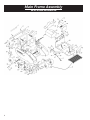
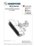
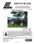
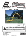
SA-25
“STAND-AER™”
STAND ON AERATOR
(S.N. 173 and Up)
Operator’s Manual and Parts List
A Division of Schiller-Pfeiffer, Inc.
www.classen-mfg.com
1028 Street Road • Southampton, PA 18966
Toll Free: 1-877-596-6337 • Fax: 1-215-357-8045
TABLE OF CONTENTS
SAFETY INSTRUCTION
MANUAL
SAFETY INSTRUCTION MANUAL . . . . . . . . . . . . . . . . . . 2
INTRODUCTION . . . . . . . . . . . . . . . . . . . . . . . . . . . . . . . . . . 2
GENERAL SAFETY INSTRUCTIONS. . . . . . . . . . . . . . . . . 2
Introduction
OWNER/USER NOTICE . . . . . . . . . . . . . . . . . . . . . . . . . . . . 2
This aerator is built to the highest standards in the industry.
However, carelessness or operator error may result in serious
injury or death. Accident and hazard prevention are dependent
upon the awareness, concern, wisdom, and proper training of
the personnel involved in the operation, transport, maintenance,
and storage of the equipment. Make sure every operator is
properly trained and thoroughly familiar with all of the
information in this manual before operating the equipment.
USER EXPERIENCE AND QUALIFICATIONS . . . . . . . . . 2
USER CLOTHING . . . . . . . . . . . . . . . . . . . . . . . . . . . . . . . . . 3
INSPECT AERATOR BEFORE EACH USE . . . . . . . . . . . . . 3
SCHEDULED AERATOR MAINTENANCE . . . . . . . . . . . . 3
WORK AREA CONDITIONS AND INSPECTION . . . . . . . 3
INITIAL OPERATING AND INSPECTION . . . . . . . . . . . . . 3
OPERATING ON SLOPES. . . . . . . . . . . . . . . . . . . . . . . . . . . 4
General Safety Instructions
OPERATION IN REVERSE. . . . . . . . . . . . . . . . . . . . . . . . . . 4
The Classen STAND-AER™ is designed with your safety in
mind. It has the following safety systems that you should be
familiar with:
OPERATION IN FORWARD DIRECTION. . . . . . . . . . . . . . 4
•
The warning decals on the aerator.
OPERATING DURING ZERO-RADIUS TURNS. . . . . . . . . 4
•
You must be standing on the foot platform while the
engine is running before the machine will move.
HYDRAULIC SAFETY . . . . . . . . . . . . . . . . . . . . . . . . . . . . . 4
•
If you get off of the foot platform while the engine
is running, the machine will become idle.
PRE-DELIVERY SERVICE OF AERATOR . . . . . . . . . . . . . 4
•
Letting go of the control arms will stop the
wheels instantly.
•
Belt and chain guards must be in place.
•
Rear wheels are provided to minimize the possibility of
tipping back and over on the operator. These should be in
the downward positions at all times for the exception of
loading unit into a vehicle or trailer. (Loading should
always be in reverse).
REPLACEMENT PARTS . . . . . . . . . . . . . . . . . . . . . . . . . . . . 4
FUEL SAFETY . . . . . . . . . . . . . . . . . . . . . . . . . . . . . . . . . . . . 4
OPERATING INSTRUCTIONS . . . . . . . . . . . . . . . . . . . . . . . 5
INSPECT AERATOR BEFORE EACH USE . . . . . . . . . . . . . 5
HOW TO START AERATOR . . . . . . . . . . . . . . . . . . . . . . . . . 5
UNUSUAL NOISES OR IRREGULAR OPERATION . . . . . 5
HOW TO DRIVE AERATOR . . . . . . . . . . . . . . . . . . . . . . . . . 5
Owner/User Notice
SERVICE AND ADJUSTMENT . . . . . . . . . . . . . . . . . . . . . . 5
POWER TRAIN PARTS LIST . . . . . . . . . . . . . . . . . . . . . . . . 9
The owner’s/user obligation is to instruct themselves and all
potential users in the safe operation of the equipment and be
sure they read and follow the instructions in this manual and
other material provided by Classen MFG., Inc. before using or
allowing others to operate the equipment. Do not use this unit
unless you carefully read, understand and follow the assembly,
installation, and safety instructions contained in the manual
and the warning decals provided on the unit. Do not let other
person’s use this unit unless you make sure they carefully read,
understand and follow these instructions. Never allow children
to operate or play on the unit.
HANDLE AND CONTROL ASSEMBLY . . . . . . . . . . . . . . 10
User Experience & Qualifications
HANDLE AND CONTROL PARTS LIST . . . . . . . . . . . . . . 11
This product is designed for use by physically fit and
experienced persons. DO NOT allow children to operate this
unit. Do not allow adults to operate the aerator without the
proper instruction mentioned above. Never allow passengers
on the aerator.
TIRE MAINTENANCE . . . . . . . . . . . . . . . . . . . . . . . . . . . . . 5
BLEEDING AIR FROM THE HYDRAULIC SYSTEM . . . . 5
DECALS . . . . . . . . . . . . . . . . . . . . . . . . . . . . . . . . . . . . . . . . . 5
MAIN FRAME ASSEMBLY . . . . . . . . . . . . . . . . . . . . . . . . . 6
MAIN FRAME PARTS LIST . . . . . . . . . . . . . . . . . . . . . . . . . 7
POWER TRAIN ASSEMBLY . . . . . . . . . . . . . . . . . . . . . . . . 8
TINE FRAME ASSEMBLY . . . . . . . . . . . . . . . . . . . . . . . . . 12
HOSES AND ADAPTERS DESCRIPTION. . . . . . . . . . . . . 13
HYDRAULIC HOSES DESCRIPTION . . . . . . . . . . . . . . . . 14
TWO YEAR LIMITED WARRANTY . . . . . . . . . . . . . . . . . 16
2
User Clothing
DO NOT operate the aerator while wearing sandals, tennis
shoes, or shorts. Always wear long non-baggy pants. Wear
high-top leather work boots with thick, textured tread at all
times. Hard or smooth soled shoes are too slippery for a good
footing on aerator platform. NEVER wear loose fitting
clothing which could get caught in the moving parts. Wearing
safety glasses, ear protection and safety shoes is advisable.
mount), and raise platform. Once platform is raised and
secured in the up position, you have access to the tines.
When you are done maintaining the tines, lower the platform,
and re-secure the 3/8” snap lock pin.
Work Area Conditions and Inspection
Replace worn rear drive tires with less than 3/32” of any tread
groove left. Grease all fittings (12 total) daily. Each grease
fitting should be filled until full.
Prior to operating the unit carefully inspect all lawn/ground
areas where you plan to use the aerator for hidden, hard-to-see
objects or uneven ground that may be hidden in the grass.
Clear the work area of moveable objects such as wire, rocks,
sprinkler heads, glass, etc. that might damage the aerator or be
thrown. Remove, if possible, or mark the location of all
immovable objects or irregular areas and be sure not to hit
them with any part of the aerator. Obstacles such as holes,
abrupt changes in the ground contour, tree trunks, stumps or
roots, stub pipes protruding from the ground, paving edges,
etc. in the path of operation can abruptly turn or stop the
aerator. This could throw you off the aerator or into and
possibly over the control handle causing serious injury or
death. The faster you are moving the more potential there is
for injury. Aerate only in daylight or in good artificial light.
Keep away from drop-offs, the edges of ponds, streams, pools,
etc. especially at the bottom of slopes. Do not aerate when
children or others are around. Never operate the aerator in an
enclosed area without good, approved ventilation. Exhaust
fumes are dangerous.
•
4 fitting on the swing arm.
Initial Operating Safety Guidelines
•
1 fitting on each of the front wheels.
•
Read and understand the warning decals on the unit.
•
1 fitting on the left and right control handles.
•
Keep a firm hold on the stationary handle at all times.
•
1 fitting on each tine disc hub.
•
Keep both feet on foot platform at all times.
•
1 fitting on each female rod end.
•
Know the controls and how to stop quickly.
Check roller chains for wear. Apply a light coat of No. 30 oil
or penetrating chain lubricant to keep the chains in proper
running order.
•
Before attempting to start engine, follow all
starting instructions.
•
Look behind before backing up.
Check roller chain(s) for tightness. Follow these steps:
•
Before leaving the operator’s position for any momentary
reasons, make sure the tines are up. Keep others from
coming near the aerator. Get back on the aerator as soon
as possible.
•
When transporting, driving onto transport vehicles, into
buildings, across parking lots or otherwise not aerating, lift
tines up.
•
When driving the machine onto a trailer, or transport
vehicle, always back the machine onto the unit, for fear of
tipping backwards.
•
Before performing any maintenance, or repair service
always turn engine off.
•
DO NOT allow inexperienced people to operate the
aerator until they have read and understood these safety
instructions. Operate the aerator at slower speeds while
becoming familiar with it.
•
Speeding is dangerous for even an experienced operator.
Sudden stops from excessive speed may cause serious
injury.
Inspect Aerator Before Each Use
DO NOT use the aerator if any parts are not maintained in
good operating condition. Examine the moving parts prior to
each use. Look for excessive wear, bald or worn tires, cracks in
parts, loose or missing bolts, cotter, lynch, or hair pins and
replace before operating the aerator. Make sure all safety
equipment provided with the aerator is in good operating order,
including all the warning decals. Inspect the rear wheels and
their respective bolts for tightness and proper operation. Ensure
that all parts of the hand-operated transmission control system
are tight and secure. This is to reduce the possibility that the
aerator could have a loss of control or safety.
Scheduled Aerator Maintenance
Model SA-25
1.
Disconnect spark plug.
2.
Take off pulley guard(s).
3.
Loosen nuts by turning counter clockwise
4.
Retighten nut by turning clockwise against lock washer.
5.
Replace pulley guard, nuts and lock washers and
retighten nuts.
DO NOT change the engine governor settings or over-rev the
engine contrary to engine manufacturer specifications. Keep
the Classen aerator in good operating condition, and keep
safety devices and shields in place and in working condition.
Keep all nuts and bolts tight to be sure the equipment is in safe
working condition. Replace worn tines. Make sure the engine
is turned off when doing ANY maintenance on unit. The
aerator should not be used after the tine strikes a foreign
object, until conducting a thorough inspection and any damage
is repaired. When changing tines, pull out and remove the 3/8”
snap lock pin (located in the upper-center of the foot platform
3
•
Keep all shields and covers in place.
Operating During Zero-Radius Turns
•
Keep hands, feet, and clothing away from moving parts.
•
Do not touch engine or muffler while engine is running or
soon after it is stopped. These areas can be so hot as to
cause severe burns.
During zero-radius turns (when one aerator wheel rotates
backwards while the other is moving forward) drive extra
slowly to reduce the possibility of losing traction or control.
•
Be alert for traffic when crossing roads or operating
near roadways.
•
Before crossing gravel drives, sidewalks or roads, lift tines
out of the ground.
Operation on Slopes
DO NOT operate on steep slopes. Do not operate aerator on
slopes steeper than you can feel secure about the ability of the
aerator. Do not operate the aerator at all when the grass is wet.
There is a danger of suddenly sliding sideways or down the
hill. When operating on a slope, travel across the grade
whenever possible, not an up or down pattern. Reduce speed
and exercise extreme caution on slopes and in sharp turns to
prevent tipping or loss of control. Be especially cautious when
changing direction on slopes.
Replacement Parts
Use of parts other than specified parts supplied by Classen
MFG., Inc., may compromise the safe use of the aerator and
is not recommended.
Operation in Reverse
Always keep a firm grip on the aerator handles with both
hands. Keep both feet firmly on the foot platform. Always lift
the tines out of the ground when reversing. Never aerate in
reverse. Operate the aerator very slowly, inching it backwards
until you become familiar with how the aerator operates and
always in an awkward location or position. Never place your
foot or feet on the ground near the back edge of the aerator
while backing up to prevent serious injury to feet or legs if
aerator were to run over you. Look behind you before backing
to prevent injuring yourself or anyone behind you.
Operation in Forward Direction
Always keep a firm grip on the aerator handles with both
hands. Operate the aerator slowly until you become familiar
with how the aerator handles. Do not operate the aerator faster
than conditions allow. For example hills, wet or bumpy ground
or dim light would all be conditions where you should work
slower than normal. Never operate the aerator at the highest
speed unless you are on a level, wide open area of clearly
visible ground or transporting on paved areas. Speeding with
the aerator is dangerous, and so is traveling faster than the
conditions should permit on this aerator. Sudden stops from
excessive speed or falling off the aerator may cause serious
injury or death.
4
Fuel Safety
Handle gasoline with care – it is highly flammable. Do not
smoke while handling gasoline. Use an approved gasoline
container. Never remove the fuel cap or add gasoline to a
running or hot engine or an engine that has not been allowed to
cool for several minutes after running. Never fill the tank
indoors and always clean up spilled gas. NEVER store the
equipment with gasoline in the tank inside a building where
fumes may reach an open flame or spark. Allow the engine to
cool before storing in any enclosure.
Hydraulic Safety
Keep body and hands away from pin holes or fittings that eject
hydraulic fluid under high pressure. Use paper or cardboard
and not hands to search leaks. Make sure all hydraulic fluid
connections are tight and all hydraulic hoses and lines are in
good condition before starting the Classen aerator.
PRE-DELIVERY SERVICE
Pre-Delivery Service of Aerator
The Classen STAND-AER™ is shipped completely assembled
and has been adjusted at the factory. However, due to the
jostling of the shipping process and the amount of time elapsed
since this was done at the factory until you receive the machine
the following items need to be repeated again before starting
the aerator:
•
Remove spark plug wire from spark plug.
•
Inspect the aerator for any damage, unusual conditions or
missing parts.
•
Inspect the aerator for all of its decals, especially the
warning decals.
•
Check (and fill if necessary) engine oil level according to
the engine manufacturing recommendation. Refer to your
Honda manual.
•
Check (and fill if necessary) hydraulic fluid level. Use
20W-50.
•
Lubricate all moving parts. Re-grease after every use.
•
Fill fuel tank with regular unleaded gasoline.
OPERATING INSTRUCTIONS
Inspect aerator before each use
Do not use aerator if any parts are not maintained in good
operating condition. Examine the moving parts prior each use.
Look for excessive wear, bald drive tires or worn out front
tires, cracks in parts, loose or missing bolts, cotter, lynch, or
hair pins and replace before operating the aerator.
How to Start the Aerator
unit. Refill the reservoir as necessary. Check for any fluid
leaks, and check the reservoir level. Add fluid if necessary.
The transmission is now ready for operation. Check the
reservoir daily for proper fluid level. It should be filled to the
top, or about 4 quarts.
Decals
•
(3) CLASSEN® decals located on front bumper and on
both sides of frame.
•
(2) STAND-AER™ decals located on both sides of frame,
under CLASSEN® decal.
•
Turn the ignition switch to the “On” position.
•
(1) DANGER decal located on left side pulley guard.
•
Turn the choke on (if engine is cold).
•
•
Pull engine rope until it starts.
(1) ALL GUARDS decal located on right side
pulley guard.
•
Turn the choke off once it’s running smoothly.
•
(2) SA-25 decals located on both sides of handle.
•
Immediately step onto the foot platform after the engine
is running.
•
(1) TINE DEPTH decal located on front left of machine.
•
(1) R.H. FORWARD/REVERSE decal located on right
upper side of handle.
•
(1) L.H. FORWARD/REVERSE decal located on left
upper side of handle.
•
(1) THROTTLE FAST/SLOW decal located on lower
right side of handle.
•
(1) SERIAL TAG located on lower left inside of handle.
•
(1) LUBRICATION TAG twist tied to engine.
•
(1) TINES decal located on upper left side of handle.
Unusual Noises or Irregular Operation
As you drive the aerator listen for any unusual noises and test
for irregular operation and adjust or service as necessary.
How to Drive the Aerator
You must stand on the aerator foot platform for the aerator to
move. Move the throttle speed to the desired speed. Once you
are standing on the foot platform, and the engine is set at the
desired speed, push both control handles away from you to go
forward, and pull them both towards you to go backwards. To
turn right pull the right control handle. To turn left pull the left
control handle. Let go of both the control handles to bring the
machine to idle position.
P/N 100074
SERVICE AND
ADJUSTMENT
P/N 100380
Tire Maintenance and Pressure
Excessively worn tire tread is dangerous on all hills. Replace
drive tires with less than 3/32” of any tread groove left. Use
only tires supplied by Classen. All six tires are foam filled and
do not hold air. You will not need to check air pressure.
P/N 100096
P/N 100350
P/N 100069
How to Bleed Air from the Hydraulic System
When any of the hydraulic parts are disconnected or removed
or when the oil is changed, air must be bled from the system.
With the bypass valve (brass nut on each of the hydraulic
pumps with a hole in the middle) closed, slowly move the
control handles in both the forward and reverse directions. As
air is purged from the unit, the oil level in the reservoir will
drop and bubbles may appear in the fluid. Refill the reservoir
as necessary.
P/N 100421
P/N 100422
P/N 100425
P/N 100073
P/N 100423
P/N 100424
Place the control handles in the neutral position and open the
bypass valve using a 5/8” wrench. Slowly move the control
handles in both the forward and reverse directions to purge the
air from the closed circuit.
Close the bypass valve and run the unit in both directions for
several minutes, until any remaining air is purged from the
P/N 100055
5
Main Frame Assembly
SA-25 STAND ON AERATOR
6
KEY
1
2
3
4
5
6
7
8
9
10
11
12
13
14
15
16
17
18
19
20
21
22
23
24
25
26
27
28
29
30
31
32
33
34
35
36
37
38
39
40
PART NO.
100074
500135
300121
500006
500106
400208
500129
500130
500042
100010
500091
500133
300119
500115
500101
400203
400216
400226
500134
400227
100043
500034
100365
400214
500228
500043
500016
400218
100380
500041
500230
500001
400206
500146
400213
100361
100017
500152
400217
500025
QTY/PER
SHEET
3
4
1
7
5
1
22
22
10
2
6
7
1
6
1
1
1
2
10
2
4
25
1
2
4
8
13
1
2
8
1
6
1
4
1
4
4
2
1
4
DESCRIPTION
DECAL, "CLASSEN"
1/2" x 2-1/2" BOLT
WEIGHT BAR
1/2" LOCK WASHER
1/2" NUT
SA-25 MAIN FRAME
3/8" NUT
3/8" LOCK WASHER
3/8" FLAT WASHER
IDLER PULLEY
3/8" x 2" BOLT
5/16" x 1" BOLT
DEPTH GAUGE PLATE
5/16" LOCK WASHER
5/16" NUT
LEFT HANDLE GUARD
REAR WHEEL LINKAGE ARM
FRONT WHEEL ASSEMBLY
3/8" x 1-1/4" BOLT
FRONT WHEEL PLATE
IDLER SPROCKET
1/2" FLAT WASHER
CYLINDER
PIVOT FLAT
1/2" x 1-1/2" BOLT w/HOLE
3/8" x 1" BOLT
5/32" x 1-1/4" COTTER PIN
SWIVEL PLATE
DECAL, "STAND-AER"
3/8" LOCK NUT
1/2" x 2" BOLT w/HOLE
1/4" x 28 GREASE FITTING
SWING ARM
3/8" x 1-1/2" BOLT
REAR TIRE FRAME
REAR WHEEL AXLE
TIRE & WHEEL ASSEMBLY, 9 x 350 x4
1/2" x 2-3/4" BOLT
DEPTH GAUGE ROD
3/8" FINE THREAD NUT
KEY
41
42
43
44
45
46
47
48
49
50
51
52
53
54
55
56
57
58
59
60
61
62
63
64
65
66
67
PART NO.
500026
400201
400215
500149
500019
400210
400211
500065
500092
100363
500079
100360
100352
400212
100346
100381
400220
400202
100069
500083
100442
300130
500232
100096
500053
300131
500182
QTY/PER
SHEET
4
1
1
1
1
1
1
4
2
2
1
1
1
1
2
1
1
1
1
6
1
1
1
1
4
4
2
DESCRIPTION
3/8" CLEVIS YOKE
CENTER PULLEY GUARD
LINKAGE ARM HANDLE
1/2" x 2" BOLT
SMALL HANDLE SPRING
THROTTLE PLATE
PLATFORM
COMPRESSION SPRING
HAIR PIN
3/8" x 3" CLEVIS PIN
3/8" x 1-3/4" BOLT
READY ROD
HANDLE GRIPS, 11" x 1"
PLATFORM MOUNT
3/8" SNAP PIN
3/8" SNAP LOCK PIN, SMALL
PLATFORM MOUNT ASSEMBLY
RIGHT HANDLE GUARD
DECAL, "DANGER"
5/16" FLAT WASHER
GOVERNOR CABLE w/CONNECTING ENDS
SWING ARM MOUNT
3/8" STUD
DECAL, "ALL GUARDS"
5/8" FLAT WASHER
2" MACHINERY WASHER
3/16" x 1-1/2" COTTER PIN
7
Power Train Assembly
SA-25 STAND ON AERATOR
8
KEY
1
2
3
4
5
6
7
8
9
10
11
12
13
14
15
16
17
18
19
20
21
22
23
24
25
26
27
28
29
30
31
32
33
34
35
36
37
38
39
40
PART NO.
500146
500042
100377
500130
500129
500134
100374
100373
500079
100382
500181
100378
300118
100315
100371
100155
100386
300125
100385
200047
500043
200049
200050
200051
100370
500135
500006
500106
500034
100043
100389
500150
100367
100388
200048
400222
300127
100248
200009
300124
QTY/PER
SHEET
4
20
1
34
38
8
1
1
8
1
1
2
4
2
2
8
2
2
2
2
24
2
2
2
2
2
10
10
2
2
2
8
2
2
2
2
2
4
4
2
DESCRIPTION
3/8" x 1-1/2" BOLT
3/8" FLAT WASHER
13 HP HONDA ENGINE
3/8" LOCK WASHER
3/8" NUT
3/8" x 1-1/4" BOLT
LEFT SIDE HYDRAULIC PUMP
RIGHT SIDE HYDRAULIC PUMP
3/8" x 1-3/4" BOLT
CLUTCH
1/4" x 1-1/2" KEY
PUMP MOUNT
PUMP BRACKET SPACER
1B-34 PULLEY
6941 V-BELT
BEARING w/COLLAR, 1" 3-BOLT
40 B-17 SPROCKET
3/4" x 1.3125 O.D. SPACER
40 B-16 SPROCKET
1" x 13-1/2" SHAFT
3/8" x 1" BOLT
CHAIN, 102 ROLLER + 1/2
CHAIN, 104 ROLLERS
CHAIN, COUPLER w/CONN LINKS
HYDRAULIC MOTOR, w/ 1/4" x 1" KEY
1/2" x 2-1/2" BOLT
1/2" LOCK WASHER
1/2" NUT
1/2" FLAT WASHER
IDLER SPROCKET
32 TOOTH SPROCKET
1/2" x 1-1/2" BOLT
MOTOR MOUNT
LARGE REAR WHEEL
1" x 7" REAR WHEEL SHAFT
1" SHAFT w/B12 x 1" SPROCKET
SPACER COLLAR
BEARING w/COLLAR, 1" 2-BOLT FLANGETTE
SPROCKET w/1" HUB, #40 X 36
JACKSHAFT SPACER
KEY
41
42
43
44
45
46
47
48
49
50
51
52
53
54
55
56
PART NO.
500101
500115
500163
500229
300129
100418
500233
500148
100429
400219
100364
100363
200052
100438
400225
100035
QTY/PER
SHEET
8
8
8
2
2
2
1
1
2
1
1
1
2
2
1
1
DESCRIPTION
5/16" NUT
5/16" LOCK WASHER
5/16" x 3/4" CARRIAGE BOLT
5 mm KEY
SPACER
SPLIT LOCK COLLAR
3/8" x 1-1/2" FINE BOLT
3/8" HEAVY WASHER
50 x 12 SPROCKET
ENGINE BRACKET
#12 SPRING
3/8" x 3" CLEVIS PIN
CHAIN, 68 ROLLERS
BEARING w/SET SCREW 1" 2 BOLT FLANGETTE
3/8" LOCK NUT RING
THROTTLE CABLE CONNECTING SPRING
9
Handle and Control Assembly
SA-25 STAND ON AERATOR
10
KEY
1
2
3
4
5
6
7
8
9
10
11
12
13
14
15
16
17
18
19
20
21
22
23
24
25
26
27
28
29
30
31
32
33
34
35
36
37
38
39
40
PART NO.
500043
500029
300137
500130
500129
500137
100480
100481
100352
400200
100368
500073
100354
500101
400207
500158
300117
500106
500006
500134
500026
500041
500025
400198
100012
100350
400197
100351
300114
100353
400196
100375
100376
500042
400199
500001
300135
500234
100425
600001
QTY/PER
SHEET
16
2
2
16
16
4
2
2
4
1
1
2
2
4
2
2
2
2
2
2
2
2
2
1
1
2
1
1
1
1
1
1
1
2
1
2
1
2
1
2
DESCRIPTION
3/8" x 1" BOLT
1/4" x 3/4" BOLT
FILTER MOUNT BRACKET
3/8" LOCK WASHER
3/8" NUT
1/4" LOCK WASHER
FILTER MOUNT
OIL FILTER
HANDLE GRIPS, 11" x 1”
RIGHT HANDLE CONTROL
THROTTLE CABLE
5/16" x 1-1/4" BOLT
FEMALE ROD END w/ ZERK
5/16" NUT
READY ROD, 3/8" x 5/16"
1/2" x 3-1/2" BOLT
BUSHING
1/2" NUT
1/2" LOCK WASHER
3/8" x 1-1/4" BOLT
3/8" CLEVIS YOKE
3/8" LOCK NUT
3/8" FINE THREAD NUT
RIGHT SIDE HANDLE
SPRING
SA-25 DECAL
LEFT SIDE HANDLE
STOMACH GUARD PAD
STOMACH GUARD PLATE
VENT PLUG
TOP MAIN HANDLE
CONTROL VALVE
CONTROL VALVE HANDLE
3/8" FLAT WASHER
LEFT HANDLE CONTROL
1/4" X 28 GREASE FITTING
CAP, HYDRAULIC
1/4" x 3/4" LAG BOLT
DECAL, "TINE DEPTH" (NOT SHOWN)
STEEL SLEEVE
QTY/PER
SHEET
1
KEY
41
PART NO.
100421
42
100422
1
43
44
100423
100424
1
1
45
46
100055
100073
1
1
DESCRIPTION
DECAL, "RIGHT, FORWARD-REVERSE"
(NOT SHOWN)
DECAL, "LEFT, FORWARD-REVERSE"
(NOT SHOWN)
DECAL, "TINE, UP-DOWN" (NOT SHOWN)
DECAL, "THROTTLE, FAST-SLOW"
(NOT SHOWN)
DECAL, SERIAL TAG" (NOT SHOWN)
LUBRICATION TAG (NOT SHOWN)
11
Tine Frame Assembly
SA-25 STAND ON AERATOR
KEY
1
2
3
4
5
6
7
8
9
10
11
12
13
14
15
16
17
18
12
PART NO.
400204
500041
100155
500043
300123
200009
700031
500003
100032
500146
100383
100384
500169
400221
500001
500147
200046
100430
QTY/PER
SHEET
1
12
4
6
2
2
2
2
36
6
2
4
72
2
2
72
1
4
DESCRIPTION
TINE MOUNT FRAME
3/8" LOCK NUT
BEARING w/COLLAR, 1"-3 BOLT
3/8" x 1" BOLT
TINE SPACER
SPROCKET w/1" HUB, 40 x 30
TINE DISC SHAFT ASSEMBLY
1/4" HALF MOON KEY
TINE
3/8" x 1-1/2" BOLT
BEARING w/SET SCREWS, 1"-3 BOLT
NYLON WASHER
5/16" LOCK NUT
TINE DISC w/HUB WELDED ON
1/4" X 28 GREASE FITTING
5/16" X 1-1/2" BOLT
TINE SHAFT
MR16RS BEARING
Hoses and Adapters Description
SA-25 STAND ON AERATOR
KEY
1
2
3
4
5
6
7
8
9
10
11
12
13
PART NO.
600062
600063
600057
600051
600058
600052
600053
600059
600054
600055
600060
600056
600050
QTY/PER
SHEET
2
2
1
1
1
1
1
1
1
1
1
1
1
DESCRIPTION
HOSE #1 (6C2AT x 23) w/1-6MJ-6MB, 2-6G-6FJX, 1-6MJ-6MB90
HOSE #2 (6C2AT x 7-1/2) w/1-6MB-6MJ, 2-6G-6FJX, 1-6MJ-8MP90, 1-1 x 1/2 BLACK BUSHING
HOSE #5 (8C2AT x 12) w/1-8MB-8MJ, 1-8G-8FJX, 1-10MB-8MJ, 1-8G-8FJX45
HOSE #6 (8C2AT x 10) w/1-8MB-8MJ, 2-8G-8FJx45, 1-10MB-8MJ
HOSE #7 (8C2AT x 12) w/1-8MB-8MJ, 2-8G-8FJX45, 1-10MB-8MJ
HOSE #8 (8C2AT x 11-1/4) w/1-8MB-8MJ, 1-8G-8FJX, 1-10MB-8MJ, 1-8G-8FJX45
HOSE #9 (6C2AT x 4-1/4) w/1-6MB-6MJ90, 2-6G-6FJX
HOSE #10 (6C2AT x 22) w/1-6MB-6MJ90, 2-6G-6FJX
HOSE #11 (8C2AT x 31) w/1-8MJ-12MP90, 2-8G-8FJX, 1-6MJ-6MJ-8MT TEE
HOSE #12 (6C2AT x 22-3/4) w/1-6MJ-6MB, 1-6G-6FJx90M, 1-6MJ-4MB45, 1-6B-6FJX45
HOSE #13 (6C2AT x 24-1/2) w/16MJ-6MB, 1-6MJ-4MB45, 1-6G-6FJX90M, 1-6G-6FJX45
HOSE #14 (6C2AT x 26-3/4) w/2-6MJ-6MB, 1-6G-6FJX
HOSE #15 (6C2AT x 25-1/2) w/1-6MJ-6MB, 1-6MJ-6MB45, 2-6G-6FJX
13
Hydraulic Hoses Description
SA-25 STAND ON AERATOR
14
See the complete line of Turf Care Products
from CLASSEN
COMPACT AERATORS
CA-18H
CA-18B
SPLIT DRIVE AERATORS
TA-25D
TA-17D
SA-25
TURF AERATORS
TA-19D
TA-26D
TOW/3PT AERATORS
48RT
60RT
72RT
3 PT AERATORS
48R
60R
72R
84R
SOD CUTTERS
SC-12
SC-18
SC-20
SC-24
TURF RAKES
TR-20H
TR-20B
TR-20MH
TR-20MB
TR-20SH
TR-20SB
TRC-20H
TRC-20B
TRS-20H
TRS-20B
TURF SEEDERS
TS-20H
TS-20B
TSS-20H
TSS-20B
TRAILERS
AST
SAT
Classen reserves the right to make changes or add improvements to its products at any time without incurring any obligation to make
such changes to products manufactured previously. Classen, or its distributors and dealers, accept no responsibility for variations
which may be evident in the actual specifications of its products and the statements and descriptions contained in this publication.
15
A Division of Schiller-Pfeiffer, Inc.
www.classen-mfg.com
1028 Street Road • Southampton, PA 18966
Toll Free: 1-877-596-6337 • Fax: 1-215-357-8045
TWO YEAR LIMITED WARRANTY
Effective April 1, 2007
For the period of two years from the date of purchase, CLASSEN MFG., INC. will repair or replace for the
original purchaser free of charge, any part or parts found upon the examination of our factory authorized
service station, or by the factory in Norfolk, Nebraska, to be defective in material or workmanship. All
transportation charges on parts submitted for repair or replacement under this warranty shall be borne by
the purchaser.
This warranty does not include engines or engine parts, tires, batteries, or gearboxes that are covered
under separate warranties furnished by their manufacturer or supplier, nor does it include normal
maintenance parts, including but not limited to, spark plugs, points, filters, blades, and lubricants.
All service under this warranty will be furnished or performed by our factory authorized service stations.
There is no other expressed warranty. Implied warranties, including those of merchantability and fitness
for a particular purpose, are limited to two years from the date of purchase and to the extent permitted by
law, any and all implied warranties are excluded. The above remedy of repair and replacement of defective
parts is the purchaser’s exclusive remedy for any defect, malfunction or breach of warranty. Liability for
incidental or consequential damages under any and all warranties is excluded to the extent permitted
by law.
NORMAL RESPONSIBILITIES OF THE SELLER AND THE USER
1.
2.
3.
4.
5.
The Distributor or Dealer is responsible for the proper assembly and preparation of the product for
delivery to the end user.
The User is responsible for reading the Manual and Instructions.
The User is responsible for proper operation and maintenance as described in the manual.
The User is responsible for the replacement of wear items such as blades, belts, tires, batteries, etc.
The User is responsible for damage due to improper operation and maintenance, as well as abuse.
All claims must be received by the factory 30 days after the end of the warranty period to receive warranty
consideration.
© 2007 Schiller-Pfeiffer, Inc.
9/07