1
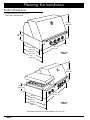
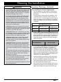
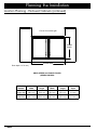
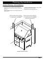
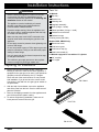
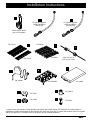
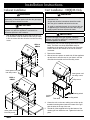
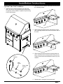
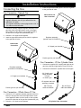
Installation Instructions
Epicure Outdoor Grill
®
Models: OB36, OB52, OBS36 and OBS52
Tested in accordance with the latest edition of
ANSI Z21.58 2006 ● cSa 1.6-2006 Standard for outdoor
cooking gas appliances. IN CANADA: INSTALLATIONS MUST
BE IN ACCORDANCE WITH THE CURRENT CAN/CG A-B149.1.
NATURAL GAS INSTALLATION CODE CAN/CG A-B149.2. PROPANE
INSTALLATION CODE AND/OR LOCAL CODE.
Part No. 102032 Rev. L
Table of Contents
Important Safety Instructions........................................... 1
Important Information About Safety Instructions............... 1
General Safety Precautions.............................................. 2
Planning the Installation.................................................... 4
Product Dimensions.......................................................... 4
Location Planning - General............................................. 5
Location Planning - Enclosed Cabinets............................ 6
Location Planning - Cart Installations............................... 9
Installation Instructions................................................... 10
Preparing for Installation................................................. 10
Cabinet Installation.......................................................... 12
Cart Installation - OB[S]36 Only...................................... 12
Connecting the Gas........................................................ 14
Final Assembly and Test................................................. 15
Verifying Proper Operation.............................................. 17
Wiring Diagrams............................................................... 18
Notes................................................................................. 20
Before You Begin...
Important:
•
Installer: In the interest of safety and to minimize problems, read these installation instructions completely and carefully before you begin the installation process. Leave these installation instructions with the customer.
•
Customer: Keep these installation instructions for future reference and the local electrical inspector’s use.
Customer Service Information
If You Need Help...
Model Identification
If you have questions or problems with installation, contact
®
your Dacor dealer or the Dacor Customer Service Team.
For repairs to Dacor appliances under warranty call the
Dacor Distinctive Service line. Whenever you call, have
the model and serial number of the appliance ready. The
model and serial number are printed on the product data
label on the back of the unit. The product data label also
specifies the power supply requirements.
OB36 36 inches wide, no side burner, three (3)
U shaped burners in main compartment
OBS36 36 inches wide, no side burner, two (2)
U shaped burners and one (1) sear burner in
main compartment
OB52 52 inches wide with side burner, three (3)
U shaped burners in main compartment
Dacor Customer Service
OBS52 52 inches wide with side burner, two (2)
U shaped burners and one (1) sear burner in
main compartment
Phone: (800) 793-0093. (U.S.A. and Canada)
Monday - Friday 6:00 a.m. to 5:00 p.m. Pacific Time
Web site: www.Dacor.com
Dacor Distinctive Service (repairs under warranty only)
Model numbers with “NG” are equipped (only) for use with
natural gas. Model numbers with “LP” are equipped (only)
for use with liquid petroleum (propane).
Phone: (877) 337-3226 (U.S.A. and Canada)
Monday - Friday 6:00 a.m. to 4:00 p.m. Pacific Time
California proposition 65 warning
The burning of gas cooking fuel generates some by-products
that are on the list of substances which are known by the State
of California to cause cancer or reproductive harm. California
law requires businesses to warn customers of potential
exposure to such substances. To minimize exposure to these
substances, always operate this unit according to the use
and care manual, ensuring you provide good ventilation when
cooking with gas.
All specifications subject to change without notice. Dacor assumes no liability for changes to specifications.
© 2008 Dacor, all rights reserved.
Important Safety Instructions
Important Information About
Safety Instructions
•
•
The Important Safety Instructions and warnings in
these instructions are not meant to cover all possible
problems and conditions that can occur. Use common
sense and caution when installing, maintaining or operating this or any other appliance.
DANGER
If you smell gas:
1.
Shut off gas to the appliance.
2.
Extinguish any open flame.
3.
Open lid.
4.
If odor continues, keep away from the appliance
and immediately call your gas supplier or your
fire department.
Always contact Dacor Customer Service about problems and conditions that you don’t understand.
warning
Safety Symbols and Labels
DANGER
Immediate hazards that WILL result in severe personal
injury or death.
warning
Hazards or unsafe practices that COULD result in severe
personal injury or death.
caution
Hazards or unsafe practices that COULD result in minor
personal injury or property damage.
1.
Do not store or use gasoline or other flammable
liquids or vapors in the vicinity of this or any
appliance.
2.
An LP cylinder not connected for use shall not
be stored in the vicinity of this or any other
appliance.
warning
If the information in this manual is not followed exactly,
a fire or explosion may result causing property damage,
personal injury or death.
warning
NEVER use this appliance as a space heater to heat or
warm the room. Doing so may result in carbon monoxide
poisoning and overheating of the appliance.
warning
This outdoor cooking appliance is not intended to be
installed in or on a recreational vehicle and/or boats.
warning
Use this outdoor gas cooking appliance outdoors only.
Do not use it in a building, garage or any other enclosed
area.
read and save these instructions
1
Important Safety Instructions
General Safety Precautions
To reduce the risk of fire, electric shock, serious injury or death when using your appliance, follow basic safety precautions, including the following:
warning
warning
• Read the use and care manual completely before
using this appliance.
• To avoid the possibility of fire, do not leave the appliance unattended when in use.
• Use this appliance only for its intended use as
described in the use and care manual. Use it only to
cook food. It is not designed for commercial, industrial or laboratory use.
• To avoid the possibility of fire or burns, do not allow
clothing, potholders, towels or rags to come into contact with hot surfaces during and immediately after
use.
• If you receive a damaged product, immediately contact your dealer or builder. Do not install or operate
an appliance that has been damaged or dropped.
• Do not use towels or bulky cloth as pot holders.
• This appliance must be properly installed and grounded by a qualified installer according to these installation instructions. Have the installer show you the
location of the gas shut-off valve and the electrical
outlet so that you know where and how to turn off the
gas supply and disconnect power to the appliance.
• Do not repair or replace any part of this appliance
unless specifically recommended in the literature
accompanying it. All other service should be done
by a qualified service technician. Contact the Dacor
Customer Service Team at (800) 793-0093, or at
www.Dacor.com for examination, repair or adjustment.
• Do not wear loose or hanging apparel while using this
appliance. Do not allow clothing to come into contact
with the cooking surface.
• Inspect the gas hose and regulator assemblies before
each use of this appliance.
• Keep items that could explode, such as aerosol cans
away from the grill and burners. Do not store flammable or explosive materials in adjacent cabinets or
areas.
• Exercise caution when opening the canopy. Let hot
air or steam escape before looking or reaching inside.
• Do not install this appliance with surface (downdraft)
ventilation systems.
• Do not use abrasives, caustic cleaners or detergents
to clean this appliance. They may cause permanent
damage to surfaces. Do not use aerosol cleaners.
They may be flammable or cause corrosion of metal
parts.
• Do not install this appliance under unprotected overhead combustible materials.
• Turn the knobs to the OFF position prior to removing
them from the valve stems.
• Excessive weight warning: Use two or more people to
move and install this product.
• Do not operate the appliance without the knobs and
trim rings in place.
• Do not install the grill in a laminate, or synthetic, solid
surface countertop material.
• Do not expose the knobs or trim rings to direct lame,
hot utensils or other sources of heat.
• Sheet metal edges can be dangerous in heavy lifting
situations. Wear gloves during installation.
• Clean the appliance thoroughly before operating it for
the first time.
• Keep the electrical cords away and gas supply lines
from heated surfaces.
• NEVER cover any slots, holes or passages on
the outdoor grill or its chassis. Doing so blocks air
flow and may cause carbon monoxide poisoning.
Aluminum foil linings may also trap heat, causing a
fire hazard. Keep all slots, holes and passages clear
of grease and grime.
• Before performing any type of service, make sure that
the gas shut-off valve is closed (turned off) and the
power plug is disconnected.
• Failure to provide proper clearances as noted in
these installation instructions may result in a fire hazard.
• DO NOT TOUCH ANY OF THE COOKING
SURFACES DURING OR IMMEDIATELY AFTER
USE. After use, make sure these surfaces have had
sufficient time to cool before touching them.
2
• In the event of a power failure, use only the Dacor
supplied match light tool or a long stemmed match to
light.
• Make sure this appliance is used only by those individuals who are able to operate it properly.
• Never allow anyone, including children to sit, stand
or climb on any part of the appliance. Doing so may
cause tipping, damage, serious injury or death.
Important Safety Instructions
warning
• Do not leave children alone or unattended in the area
around the appliance. Do not allow children to operate it, play with the controls, pull on the handle or
touch other parts.
• Do not store items of interest to children on top of
or above the appliance. Children could be burned or
injured while climbing on it.
• Keep the ventilation openings for the LP cylinder free
and clear from debris.
• Non-stick coatings, when heated, can be harmful to
birds. Remove birds to a separate, well-ventilated
area during cooking.
• Make sure that all of the appliance’s parts are dry
before lighting a burner. Do not cover the burners and
grates with anything except properly selected utensils. Decorative covers may cause a fire hazard or
damage to the unit if a burner is accidentally burned
on with the cover in place.
• Keep flammable items, such as paper, cardboard,
plastic, and cloth away from the burners and other
hot surfaces. Do not allow pot holders to touch hot
surfaces or gas burners.
• Do not hang flammable or heat sensitive objects over
or in close proximity to the appliance.
• Do not use the appliance for storage.
• Make sure that all the burner parts are dry before
lighting a side burner.
• Do not allow food to sit for more than one hour before
or after cooking. Eating spoiled food can result in
food poisoning.
warning
• IMPORTANT: This appliance is equipped with a
three-prong grounding electrical plug for protection
against possible electric shock hazards. It must be
plugged into a dedicated, grounded electrical outlet
that meets local codes for outdoor appliances. If only
a two-prong electrical
outlet is available, it
is the responsibility of
the customer to have it
replaced with a dedicated, properly grounded
three-prong electrical
outlet. Do not under any
circumstances:
◊ Cut or remove the third (ground) prong from the
power cord.
◊ Use an adapter plug.
◊ Use a power cord that is frayed or damaged.
• If using an extension cord, use only a grounded cord
approved for use outdoors. Use a cord that is as
short as possible. Avoid routing it through wet areas.
TO REDUCE THE RISK OF INJURY TO PERSONS IN
THE EVENT OF A GREASE FIRE:
• SMOTHER FLAMES with a close-fitting lid, cookie
sheet or metal tray, then turn off the burner. BE
CAREFUL TO PREVENT BURNS. If the flames do
not go out immediately, EVACUATE AND CALL THE
FIRE DEPARTMENT.
• NEVER PICK UP A FLAMING PAN - you may be
burned.
• Do not line the appliance with aluminum foil or other
materials. These items can melt or burn up during
cooking.
• DO NOT USE WATER, including wet dish cloths or
towels - a violent steam explosion may result.
• Do not leave the canopy open when the outdoor grill
is not in use to prevent an accumulation of water/
moisture inside. If water accumulates in the grill compartment the unit should not be used and a service
technician should be called to clean the inside of the
compartment.
a. You have a Class ABC extinguisher, and you
already know how to operate it.
• If the appliance is left out in the rain (with the canopy
shut), wait 30 minutes after the rain storm before
using it.
d. You can fight the fire with your back to an exit.
• Use a fire extinguisher ONLY if:
b. The fire is small and contained in the area where
it started.
c. The fire department is being called.
3
Planning the Installation
Product Dimensions
Product tolerances: ±1/16 (±1.6 mm)
unless other wise specified
25 1/8"
(63.8 cm)
9 1/8"
(23.2 cm)
23 3/4"
(60.3 cm)
36"
(91.4 cm)
26 1/2"
(67.3 cm)
27” *
(68.6 cm)
OB36 and
OBS36
25 1/8"
(63.8 cm)
9 1/8"
(23.2 cm)
23 3/4"
(60.3 cm)
26 1/2"
(67.3 cm)
27" *
(68.6 cm)
52"
(132.1 cm)
OB52 and
OBS52
* Total depth from back to front of handles is 30” (76.2 cm)
4
Planning the Installation
warning
Location Planning - General
• This installation must conform to local codes or, in the
absence of local codes, with either the National Fuel
Gas Code, ANSI Z223.1/NFPA 54, Natural Gas and
Propane Installation Code, CSA B149.1, or Propane
Storage and Handling Code, B149.2.
Gas and Electric Power Requirements
•
Prior to installation, the gas supply for natural gas or
whole house LP installations must meet the specifications below.
• Prevent grill combustion products from being drawn
into a building through fresh air inlets: The venting
system of other than a direct-vent appliance must
terminate at least 4 feet (1.2 m) below, 4 feet (1.2 m)
horizontally from, or 1 foot (30.5 cm) above any door,
window or gravity air inlet into any building. The bottom of the vent terminal must be located at least 12
inches (30.5 cm) above grade.
•
For natural gas or whole house LP installations, have
a qualified plumber or gas fitter install a 3/4 inch (1.9
cm) or 1/2 inch (1.3 cm) gas supply line with a shut-off
valve (not included). Have it installed in an accessible
location that allows it to be shut off when the appliance
is installed.
• A MINIMUM clearance of 10 inches (25.4 cm) must
be maintained, above the countertop material, from all
combustible vertical materials on the sides and behind
the outdoor grill chassis and canopy.
• A MINIMUM clearance of 1 1/4 inches (3.2 cm) must
be maintained, above the countertop material, from all
non-combustible vertical materials on the sides and
behind the outdoor grill chassis and canopy.
Gas Supply Requirements
Model Type
Manifold Pressure
Minimum Gas
Supply Pressure
Natural Gas
4” Water Column
5” Water Column
LP Gas
11” Water Column
12” Water Column
•
• A MINIMUM clearance of 1/4 inch (6 mm) must be
maintained, inside the base enclosure below the
countertop material, from all vertical surfaces on the
sides of the appliance.
• A MINIMUM clearance of 3/4 inch (1.9 cm) must be
maintained, from the bottom of the control panel to
any material for ventilation purposes. Failure to do so
will block air flow through the outdoor grill and may
cause carbon monoxide poisoning or improper operation.
Electrical Requirements
Circuit Requirement
Total Connected Load
• The maximum gas supply pressure to the regulator
must not exceed 1/2 pound per square inch.
• Use only the factory supplied gas regulator or a Dacor
approved replacement.
120 Vac, 15 Amp.
2.9 Amps, (0.35 kW)
•
It is the owner’s responsibility to ensure that the electrical connection to this appliance is installed by a
qualified electrician. The electrical installation, including minimum supply wire size and grounding, must be
done in accordance with National Electric Code ANSI/
NPFA 70, (or the latest revision) or Canadian Electrical
Code CSA C22.1, and local codes and ordinances for
connection of an outdoor appliance.
•
Locate the electrical outlet within reach of the 48 inch
(121.9 cm) long power cord so that it will reach when
the grill is completely installed in the enclosure.
•
Total connected loads shown include the ignition system, interior lights and rotisserie motor.
•
The rotisserie motor should be plugged into the same
grounded outlet power source or an alternate 120 Vac
duplex outlet located on the same circuit as the grill.
• The back edge of the grill must maintain a minimum
clearance (10 inches/25.4 cm) from combustible back
splash materials. Special cabinet and countertop
dimensions are required.
• The electrical outlet and gas service must be installed
only by a qualified, licensed professionals.
Correct voltage, frequency and amperage must be supplied to the appliance from an isolated, grounded circuit
which is protected by a properly sized circuit breaker or
time-delay fuse. The required voltage, frequency, and
amperage ratings are listed on the product data plate
and are also below.
5
Planning the Installation
Location Planning - Enclosed
Cabinets
Enclosed Cabinet Installations with a LP
Cylinder
•
Maintain all minimum clearances specified below and
on the facing page.
•
For proper outdoor grill operation, provide a flat, level
mounting surface with minimum 3/4” (1.9 cm) thickness.
•
All models are designed to allow installation in combustible or non-combustible base material structures.
•
On installations without a LP cylinder tank located
below the unit, plan the installation so that the gas
shut-off valve and pressure regulator are accessible
after the appliance is installed so that gas and power
can be turned off if service is required. Also, make sure
the electric plug can be disconnected easily during service.
•
When using a LP-gas cylinder, it must be completely
enclosed, It must also be ventilated by openings on
the sides, back and floor of the enclosure. Each opening must have a total area of no less than 10 square
inches (25.4 square cm).
•
Plan to install the grill in a base structure that has one
of the following structural details:
◊
The LP cylinder shut-off valve shall be readily
accessible for hand operation. A door on the enclosure to gain access to the valve is acceptable, provided it is non-locking and can be opened without
the use of tools.
◊
The enclosure for the LP-gas cylinder shall isolate
the cylinder from the burner compartment to provide shielding from radiation, a flame barrier and
protection from foreign materials such as hot drippings.
◊
There shall be a minimum clearance of 2 inches
(51 cm) between the floor of the LP-gas cylinder
enclosure and the ground. The design of the outdoor cooking enclosure must allow the LP-gas cylinder to be connected, disconnected and the connections inspected and tested outside the cylinder
enclosure.
Optional Finish Trim Kits
The optional finish trim can be installed on the countertop
to finish the sides and back of the countertop opening. The
stainless steel finish trim can be caulked to the countertop
and should be secured to the base enclosure with flat head
screws. Center the trim within the cutout dimensions noted
in this manual, then utilizing the deck screws along with
the holes located along the vertical sides of the finish trim,
install them securely to the base enclosure countertop substraight.
•
Connections which may be disturbed when installing
the cylinder in the enclosure can be leak tested inside
the enclosure.
•
Internal mounting means shall be provided on the outdoor gas grill for mounting the LP-gas supply cylinder.
If the outdoor grill is not in use, the gas must be turned
off at the supply cylinder.
10" (25.4 cm) min. to combustibles
1 1/4" (3.2 cm) min. to non-combustible
28 1/2" (72.4 cm)
to finished
countertop
1 1/4"
(3.2 cm)
Junction
box
Cutout Dimensions - Side View
(All Models)
1/4"
Rotisserie mounting
bracket (factory installed) (6 mm)
3/4" (1.9 cm)
min. to any
material*
6
23 3/4" (60.3 cm)
24" (61.0 cm)
Trim frame
(accessory)
Planning the Installation
Cutout tolerances: +1/16 (+1.6 mm), -0
unless other wise specified
Coutertop
depth
25"
(63.5 cm)
6" x 7"
(15.2 cm x 17.8 cm)
utility cutout
Cabinet
depth
24"
(61.0 cm)
12 1/4"
(31.1 cm)
3/8" (1.0 cm) ø
both sides
OB[S]36 - 33 1/2" (85.1 cm)
OB[S]52 - 49 1/2" (125.7 cm)
Outdoor grill placement
1 1/2" (3.8 cm)
Cutout Dimensions - Top View
OB[S]36 - 36 1/2" (92.7 cm)
OB[S]52 - 52 1/2" (133.4 cm)
9" (22.8 cm)
max.
36"
(91.4 cm)
3/4" (1.9 cm)
min. to any
material for
ventilation
8" (20.3 cm) min.
to combustibles
above the countertop
surface, both sides
Door depth: 1/4” 6 mm)
Cutout Dimensions - Front View
OBAD36 Accessory doors shown
7
Planning the Installation
Location Planning - Enclosed Cabinets (continued)
Cut-out for outdoor grill
Overall
height
Overall width
Door depth: 1/4” 6 mm)
OBAD SERIES ACCESSORY DOORS
(OBAD36 SHOWN)
8
Model
Number
Overall
Width
Overall
Height
Cutout
Width
Cutout
Height
Cutout
Depth
OBAD20
(Single door)
19 1/2”
(49.5 cm)
21”
(53.3 cm)
16 3/4”
(42.5 cm)
18 3/4”
(47.6 cm)
3”
(7.6 cm)
OBAD36
(Dual door)
35 7/8”
(91.1 cm)
21”
(53.3 cm)
33 1/8”
(84.1 cm)
18 3/4”
(47.6 cm)
3”
(7.6 cm)
Planning the Installation
Location Planning - Cart Installations
•
Maintain all minimum clearances shown between the
appliance and all surfaces behind and to the side of the
appliance.
•
Allow 26 inches minimum in front to open and close the
cabinet drawers.
Above
surface, both
bothsides:
sides:
Above the
the cooking
cooking surface,
111/4”
1/4” (32mm)
(3.2 cm) Min.
min. to
to non-combustibles
non-combustibles
10”
10” (254mm)
(25.4 cm) Min.
min. to combustibles
combustibles
•
For proper grill and drawer operation, use the outdoor
grill and cart only on a level surface.
•
Side distances exclude optional shelves.
Above
cookingsurface,
surface,behind
behindunit:
unit:
Above
the cooking
2 1/2”
(64mm)
Min.
to non-combustibles
2 1/2”
(6.4
cm) min.
to non-combustibles
1/4"
(286mm)
Min.
to combustibles
1111
1/4”
(28.6
cm) min.
to combustibles
(with
hood
in closed
position)
(with
hood
in closed
position)
Example of Grill Cart Location
9
Installation Instructions
warning
• Before installing the appliance, make sure the electrical and gas (on tank-less installations) service
meets the requirements specified in the Planning the
Installation section of this manual.
• This appliance must be installed by a licensed
plumber or gas fitter when installed within the
Commonwealth of Massachusetts.
• Excessive weight warning: Since the appliance and
grill cart are heavy, install the appliance with the help
of at least one other person.
• Make sure the power cord is NOT connected to the
electrical outlet while connecting the gas line to the
appliance.
Parts List
All Models:
A Drip tray B Smoker box
C Warming rack
D Regulator assembly
E Grills (2 large, 2 small)
F Flame spreaders (2 large, 1 small)
G Rotisserie rod and forks
H Rotisserie motor
Cleaning cream (PN A302)
Models OB52, OBS52 Only:
• Do not apply excessive pressure when tightening connections and fittings.
L Side burner cover
• Do not use plumber’s putty or Teflon tape on gas compression connections. Doing so can defeat the proper
sealing of these fittings.
M Side burner caps (2)
• Use only approved gas line thread compound or tape
to seal gas connections.
• The maximum gas supply pressure to the regulator
must not exceed 1/2 pound per square inch.
K Side burner grate
N Side burner heads (2)
LP Models equipped for use with an LP cylinder:
P 3/4” coupling
Q 3/4” nipple
Preparing for Installation
A
1. Before removing the unit from the box, check the
labeling on the box to make sure that the appliance is
equipped for the gas type to be used. Liquid petroleum
(propane) units are identified by the “LP” designation at the end of the model number. Do not proceed
with installation if you do not have the correct model.
Conversion in the field from one gas type to another is
not permissible.
2. With the help of an assistant, remove the appliance
and all the parts from the box. Check to make sure all
parts are included.
PN 700481
B
3. Remove all shipping materials from the appliance and
peel off the protective plastic coating.
4. To reduce weight during installation, make sure all
loose parts are removed from the grill.
PN 27738
C
PN 101154
10
Installation Instructions
D
D
D
LP cylinder regulator
OB36 and OBS36
(PN 72310)
LP cylinder regulator
OB52 and OBS52
(PN 101578)
Whole house natural
gas or LP regulator*
E
PN 101163
PN 36628
F
PN 36661
PN 101164
G
Rod: PN 101179
Fork (2): PN 72162
L
K
H
PN 700482
M
N
PN 72436SB
P
PN 72231
PN 72232
Q
PN 13548
PN 700614
PN 72801
* A whole house gas regulator comes standard with natural gas models (Dacor PN 700597NG. For whole house LP
installations, replace the standard LP tank regulator and hose that come with LP models with a whole house LP regulator
(Dacor PN 700597LP). The whole house LP regulator must be ordered separately.
11
Installation Instructions
Cabinet Installation
Cart Installation - OB[S]36 Only
warning
warning
To avoid an explosion hazard, do not connect the cart or
appliance(s) to electrical power until after the gas supply
system has been checked for leaks.
important
To prevent damage to the gas regulator, install the
regulator only after the appliance is mounted in its
permanent position in the enclosure.
•
With at least one person on each side of the unit, lift
it up and lower it into the cabinet cutout. As you lower
it into the cutout slide the electrical cord into the utility
cutout.
OB36 or
OBS36
• Attach the appliance to the cart with all of the supplied
bolts before use.
• All gas and electrical connections should be made
after the grill is installed and bolted to the cart.
• To avoid an explosion hazard, do not connect the cart
or appliance(s) to electrical power until after the gas
supply system has been checked for leaks.
important
To prevent damage to the gas regulator, install the
regulator only after the appliance is mounted in its
permanent position on the cart.
1. Remove the cart from the shipping pallet before installation. The Dacor cart ships assembled ready for
installation of the outdoor grill. Set the cart in an open
location and lock the wheels on the cart to minimize
movement.
2. Remove the drawers.
3. With at least one person on each side, lift the appliance
up and lower it onto the cart. As you lower it onto the
cart slide the electrical cord into the utility cutout.
Insert power cord
into utility cutout
Insert power cord
into utility cutout
OB52 or
OBS52
Utility cutout
Locking
wheel
Rotating wheel
Tank shelf
Locking wheel
4. Center the unit on the cart, making sure to line up the
threaded mounting holes under the bottom of the grill
with the holes in the top of the cart.
Insert power cord
into utility cutout
12
5. Thread all of the supplied bolts into the bottom of the
outdoor grill from inside the cart. Tighten the bolts into
place.
Installation Instructions
Optional Side Shelf Installation
1. Install the front mounting bracket for the right side
shelf. Use two (2) of the provided button head fasteners and two (2) lock washers. Tighten into place using
a 5/32” Allen wrench.
2. Slide the slot on the inside of the shelf over the pin on
the mounting bracket.
Pin
3. While holding the shelf in place, insert the pin on the
back mounting bracket into the slot on the back side of
the shelf.
4. While holding the shelf and back mounting bracket in
place, attach the back mounting bracket using two (2)
of the provided button head fasteners and two (2) lock
washers.
Bracket
Lock
washer
Button head
fastener
5. Repeat steps 1 through 4 for the other shelf.
13
Installation Instructions
Connecting the Gas
3. Install an approved flexible gas line from the regulator
to the gas shut-off valve.
Gas Connection - Natural Gas
note
Whole House LP
Gas Connection
• Units equipped for use with natural gas ship with a
regulator assembly with 3/4” pipe attached and an
additional 3/4” nipple.
• The regulator assembly is also equipped with a 3/4” to
1/2” reducer on the inlet side.
1. Connect the factory supplied regulator assembly to the
gas inlet at the back right bottom corner of the appliance. Make sure the arrow on the regulator points in
the direction of the gas flow (towards the grill).
2. Connect a 1/2” nipple to the regulator.
3. Install an approved flexible gas line from the regulator
to the gas shut-off valve.
Natural Gas
Connection
Regulator assembly
(special order PN 700597LP)
1/2” Nipple (not included)
Flexible gas line (not included)
Gas Connection - LP Gas Cylinder Hose
Regulator assembly
(included PN 700597NG)
1/2” Nipple (not included)
1. Connect the supplied 3/4” coupling and nipple to the
gas inlet at the back right bottom corner of the unit.
2. Connect the included LP cylinder hose to the nipple.
3/4” Coupling and
nipple (included)
Connect
to outdoor grill
LP regulator and hose
assembly (included)
Flexible gas line (not included)
PN 72310 for
OB36 and OBS36
PN 101578 for
OB52 and OBS52
Gas Connection - Whole House LP Gas
1. Connect the LP regulator assembly (special order from
Dacor) to the gas inlet at the back right bottom corner
of the appliance. Make sure the arrow on the regulator
points in the direction of the gas flow (towards the grill).
2. Connect a 1/2” nipple to the regulator.
14
LP Cylinder Hose Connection
Installation Instructions
Final Assembly and Test
Assemble the Side Burner - 52 Inch Models
Assemble the Grill
1. Open the canopy on the unit.
2. Insert the drip tray completely into the slot on the front
of the unit.
3. Put the flame spreaders on the floor of the appliance,
inside the canopy. The large holes go toward the front
of the unit. The holes are used to light the burners in
case of power failure. Push the spreaders as far to the
right as possible, leaving an opening on the left for the
smoker box.
7. Put the burner heads on to the burner bases. Line up
the slots on each head with the pins on the base so
that it lies flat. Put the burner caps on top of the burner
heads. Line up the slots on each cap with the pins on
the base so that it lies flat.
8. Put the grate over the top of the side burner. Line up
the legs with the dimples on the top of the side burner
chassis.
4. Install the grills on the shelves above the flame spreaders. Push the grills as far to the right as possible, leaving an opening on the left for the smoker box.
5. Insert the smoker box into the opening to the left side
of the grills.
9 Burner cover
6. Place the warming rack on the holders on the walls
inside the canopy.
8 Grate
5 Smoker box
7 Burner heads and caps
4 Grills
1 Open canopy
3 Flame spreaders
6 Warming rack
2 Drip tray
15
Installation Instructions
Final Assembly and Test (cont.)
1. For units that will use a LP cylinder, start by making
sure the tank shut-off valve is completely closed.
LP Cylinder Installation - Some Models
2. Place the tank into the final position within the cabinet
or cart.
warning
• The largest recommended LP cylinder size for the
rollout tank shelf on the cart is five gallons. A five
gallon portable liquid propane cylinder should be
approximately 12 inches (30.5 cm) in diameter and
18 inches (45.7 cm) high,. It must be constructed and
marked in accordance with the specification for liquid
propane (LP) gas cylinders of the U.S. Department
of Transportation (DOT) and designed for use with a
5LP-A quick disconnect systems only.
• Cylinders must be stored outdoors in a well vented
area out of the reach of children.
Gas connection at
right rear corner
under outdoor grill
Tank gas
regulator (included)
LP tank valve
• On installations with a LP cylinder, when storing the
appliance indoors, you must disconnect and store the
LP cylinder outdoors.
• On models OB52 and OBS52 equipped for use with
a LP tank, use only a two stage regulator on the gas
supply line.
• For LP cylinder installations, the LP gas cylinder must
have its own certified high-pressure regulator (Either
Type I or No. 600 Connection).
• A dented or rusty LP tank may be hazardous and
should be checked by your LP supplier.
• Never use a cylinder with a damaged shut-off valve.
• Do not change the regulator/hose assembly with a
standard 510 POL tank/valve assembly.
• The cylinder must be provided with a shut-off valve
terminating in a liquid propane (LP) gas supply cylinder valve outlet specified, as applicable, for connection No. 5LP-A.
• The cylinder supply system must be arranged for
vapor withdrawal and provided with a listed overfilling
prevention device.
Flexible gas
line (included)
Slideout LP tank
storage shelf on
optional cart
LP tank
(not included)
5 Gallon maximum
shelf capacity
Leak Testing
warning
• Do not use a flame to check leaks.
• The grill or cooktop and shut-off valve must be disconnected from the gas supply piping during any pressure testing exceeding 1/2 psi (3.5 kPA).
1. Turn all burner control knobs on the front
of the appliance to the OFF position.
2. With the power to the appliance
DISCONNECTED, open the gas shut-off
valve.
OFF
3. Check all gas connections for leaks using an electronic
gas leak detector. You may also apply a water and
soap solution to the connections. Bubbles around the
connections indicate a leak. If you observe leakage do
not attempt to operate the appliance until all leaks have
been eliminated.
Power Connection - Cart Models
1. If the appliance is installed on a cart, connect a threeprong extension cord (minimum 5 Amp. capacity)
designed for outdoor use to the power input on the
back of the cart. Connect the other end of the extension cord to a grounded, three-prong, electrical outlet
that meets local code for use with outdoor appliances.
16
Installation Instructions
2. With the tank shelf open, connect the power cord from
the outdoor grill and the warming oven (if equipped with
one) to the electrical outlet on the back panel inside the
cart.
3. Connect the rotisserie motor power cord to the electrical outlet on the back side of the cart.
6. If the second or third attempt to ignite the burner is
not successful then turn all burner controls to the OFF
position.
7. If the grill or cooktop fails to operate properly, make
sure that power to the electrical outlet and gas supply
are turned on and that all installation steps have been
carefully followed. Check also for a tripped ground
fault interrupter on the electrical outlet. Push in on the
RESET button.
NOTE: If using an extension cord, the igniters will
not spark properly if the cord is not supplying a solid
ground.
If the grill still will not light, close the gas shut-off valve. Do
not attempt to repair the appliance yourself. Contact Dacor
Distinctive Service at (877) 337-3226. Have the model and
serial number from the product data label available when
you call.
Electrical Outlet with Ground Fault Interrupter
Power Connection - Cabinet Installations
•
•
Connect the appliance(s) to an electrical outlet
that meets the specifications in the Planning the
Installation section.
The rotisserie motor should be plugged into the same
outlet or an alternate 120 Vac outlet on the same circuit
as the appliance.
Verifying Proper Operation
Lighting Instructions
1. Read and understand the accompanying use and care
manual prior to cooking with this appliance. The use
and care manual contains additional important safety,
service and warranty information.
2. No adjustment of burner settings is required. All valves
and air mixture shutters found in this appliance have
been factory preset.
3. With the gas shut-off valve open, turn all
burner knobs to the HIGH position for
approximately 20 seconds to allow the air
in the system to purge from the grill and
cooktop side burners.
4. Once the gas has filled the lines the automatic electronic ignition system should
ignite the burner. If the system burners
do not ignite within 20 seconds turn all
burner controls to the OFF position. Wait
five minutes and attempt the ignition process again.
Dacor is not responsible for the cost of correcting problems
caused by a faulty installation.
Installation Checklist
warning
• To ensure a safe and proper installation, the following checklist should be completed by the installer to
ensure that no part of the installation has been overlooked.
• Proper installation is the responsibility of the homeowner. The importance of proper installation of your
Dacor Outdoor Grill cannot be over emphasized.
□□ Is the electrical outlet for the appliance grounded and
located according to these instructions and in accordance with all applicable electrical codes for outdoor
appliances?.
□□ Is the gas service for the appliance located and
installed according to these instructions and in accordance with all applicable codes?
□□ Has the gas supply inlet pressure been measured to
ensure that it does not exceed the maximums and
meets the minimum stated in these instructions?
HIGH
□□ Is the appliance secured to the cabinet or cart?
□□ Are the grease tray, flame spreaders, grates and, if
applicable, burner heads and caps properly installed
according to these instructions?
OFF
5. Visually check the burner flame for proper operation.
Proper flame operation will show a steady, soft blue
color and stable flame.
□□ Has proper operation been verified? Did the installer
check the gas supply for leaks?
□□ Have any problems been noted on the warranty card
or during the on-line warranty activation? Has the warranty been activated on-line or the warranty card filled
out completely and mailed?
17
Wiring Diagrams
Wiring Diagram - OB(S)36
18
Wiring Diagram - OB(S)52
Wiring Diagrams
19
Notes
20
21
Dacor ● 600 Anton Blvd. Suite 1000 Costa Mesa, CA 92626 ● Phone: (800) 793-0093 ● Fax: (626) 403-3130 ● www.Dacor.com