1
TM-H6000III
Technical Reference
Guide
❏
Receipt and Slip model
❏
with MICR model
❏
with Endorsement model
❏
with Validation model
❏
with Endorsement and MICR model
❏
with Validation and MICR model
❏
with Image Scanner model
❏
Photo-ID Model with Image Scanner model
English
410307004
Rev. E
TM-H6000III Technical Reference Guide
CAUTIONS
❏
This document shall apply only to the product(s) identified herein.
❏
No part of this document may be reproduced, stored in a retrieval system, or transmitted in any form or by any
means, electronic, mechanical, photocopying, recording, or otherwise, without the prior written permission of
Seiko Epson Corporation.
❏
The contents of this document are subject to change without notice. Please contact us for the latest information.
❏
While every precaution has been taken in the preparation of this document, Seiko Epson Corporation assumes no
responsibility for errors or omissions.
❏
Neither is any liability assumed for damages resulting from the use of the information contained herein.
❏
Neither Seiko Epson Corporation nor its affiliates shall be liable to the purchaser of this product or third parties
for damages, losses, costs, or expenses incurred by the purchaser or third parties as a result of: accident, misuse, or
abuse of this product or unauthorized modifications, repairs, or alterations to this product, or (excluding the U.S.)
failure to strictly comply with Seiko Epson Corporation's operating and maintenance instructions.
❏
Seiko Epson Corporation shall not be liable against any damages or problems arising from the use of any options
or any consumable products other than those designated as Original EPSON Products or EPSON Approved
Products by Seiko Epson Corporation.
TRADEMARKS
Microsoft, Windows NT, Windows 2000, Windows XP, Windows Vista, Visual Basic and Visual C++ are trademarks
and registered trademarks of Microsoft Corporation, USA.
Java and JavaPOS are trademarks or registered trademarks of Sun Microsystems, Inc.
EPSON® and ESC/POS® are registered trademarks of Seiko Epson Corporation.
General Notice: Other product and company names used herein are for identification purposes only and may be
trademarks of their respective companies.
ESC/POS® Proprietary Command System
EPSON took the initiative by introducing ESC/POS, a proprietary POS printer command system including patented
commands and enabling versatile POS system construction with high scalability. Compatible with all types of EPSON
POS printers and displays, this proprietary control system also offers the flexibility to easily make future upgrades. Its
popularity is worldwide.
Rev. E
iii
Revision Information
Revision
Page
Altered Items and Contents
Rev. A
all pages
Newly authorized
Rev. B
all pages
The validation model added
Rev. C
iv
“Restriction of Use” added
viii
Caution for the manual cutter added
Caution for aerosol sprayers added
iv
Rev. D
all pages
Add the Image scanner model and the Photo-ID model.
Rev. E
all pages
UPOS information updated
Rev. E
TM-H6000III Technical Reference Guide
About This Manual
Aim of the Manual
This manual was created to provide the information on the TM-H6000III printer for anyone who
is developing hardware, installations, or programs. Programmers will also want to consult other
documents.
Contents of the Manual
Chapter 1 General Information:
Chapter 2 System Planning:
General description of features plus specifications.
Contains introduction of control methods (APD,
OPOS, JavaPOS, and ESC/POS) and each
connection form.
Chapter 3 Setup:
Contains information on such matters as DIP
switches, memory switches, error processing for
using TM-H60000III.
Chapter 4 Maintenance & Troubleshooting: Contains useful information for using.
Chapter 5 Application Development
Contains useful information for programming.
Information for UPOS:
Chapter 6 Application Development
Contains useful information for programming.
Information for APD:
Chapter 7 Application Development for
Contains useful information for general
Image Scanner:
programming with the TM-H6000III.
Appendix A Character Code Tables:
Contains the character code tables.
Appendix B Power Supply Specifications: Contains the specifications.
Appendix C FAQ:
Contains FAQ for interfaces.
Appendix D Comparison Table:
Comparison table for TM-H6000II with Image
Scanner, TM-H6000II Photo-ID Model, TMH6000III with Image Scanner, TM-H6000III PhotoID Model.
Key to Symbols
The following symbols are used in the documentation for this product. See the specific warnings
and cautions at appropriate points throughout this guide.
WARNING:
Warnings must be followed carefully to avoid serious bodily injury.
CAUTION:
Cautions must be observed to avoid minor injury to yourself or damage to your
equipment.
Note:
Notes have important information and useful tips on the operation of your printer.
Rev. E
v
Restriction of Use
When this product is used for applications requiring high reliability/safety such as
transportation devices related to aviation, rail, marine, automotive etc.; disaster prevention
devices; various safety devices etc; or functional/precision devices etc, you should use this
product only after giving consideration to including fail-safes and redundancies into your
design to maintain safety and total system reliability. Because this product was not intended for
use in applications requiring extremely high reliability/safety such as aerospace equipment,
main communication equipment, nuclear power control equipment, or medical equipment
related to direct medical care etc, please make your own judgment on this product’s suitability
after a full evaluation.
Related Software and Documents
Related software and documents
Software/document name
Description
TM-H6000III User’s Manual
Provides basic handling procedures to enable POS
operators to use the TM-H6000III safely and correctly. This
manual is packed in the box with the printer.*
ESC/POS Application Programming Guide
Provides detailed ESC/POS command information used
by each TM printer, along with sample programs and
other information about the printers. Contact us to
obtain this guide.*
TM-H6000III Technical Reference Guide
This guide.*
EPSON OPOS ADK
This is an OCX driver.*
EPSON OPOS ADK Manual
Provides information for anyone who is programming
using OPOS. This is included in the EPSON OPOS ADK.*
EPSON Advanced Printer Driver (APD)
This is a Windows driver.*
This provides instructions on using the driver and
programming methods. Sample programs are also
included.
* You can obtain these items from one of the following URLs:
For customers from North America, go to the following web site: http://www.epsonexpert.com/
For customers in other countries, go to the following web site: http://www.epson-pos.com/
vi
Rev. E
TM-H6000III Technical Reference Guide
Safety Precautions
EMC and Safety Standards Applied
Product Name: TM-H6000III
Type Name: M147G
The following standards are applied only to the printers that are so labeled. (EMC is tested using the EPSON power
supplies.)
Europe:
CE marking
Safety: EN 60950
North America:
EMI: FCC/ICES-003 Class A
Safety: UL 1950/CSA C22.2 No. 950
Japan:
EMI: VCCI Class A
Oceania:
EMC: AS/NZS CISPR22 Class B
WARNING
The connection of a non-shielded printer interface cable to this printer will invalidate the EMC standards of this
device.
You are cautioned that changes or modifications not expressly approved by Seiko Epson could void your authority to
operate the equipment.
CE Marking
The printer conforms to the following Directives and Norms
Directive 89/336/EEC
EN 55022
M147G: Class B
EN 55024
IEC 61000-4-2
IEC 61000-4-3
IEC 61000-4-4
IEC 61000-4-5
IEC 61000-4-6
IEC 61000-4-8
IEC 61000-4-11
FCC Compliance Statement
For American Users
This equipment has been tested and found to comply with the limits for a Class A digital device, pursuant to Part 15 of
the FCC Rules. These limits are designed to provide reasonable protection against harmful interference when the
equipment is operated in a commercial environment.
This equipment generates, uses, and can radiate radio frequency energy and, if not installed and used in accordance
with the instruction manual, may cause harmful interference to radio communications. Operation of this equipment in
a residential area is likely to cause harmful interference, in which case the user will be required to correct the
interference at his own expense.
Rev. E
vii
For Canadian Users
This Class A digital apparatus complies with Canadian ICES-003.
Cet appareil numérique de la classe A est conforme à la norme NMB-003 du Canada.
GEREÄUSCHPEGEL
Gemäß der Dritten Verordnung zum Gerätesicherheitsgesetz (Maschinenlärminformations- Verordnung-3. GSGV) ist
der arbeitsplatzbezogene Geräusch-Emissionswert kleiner als 70 dB(A) (basierend auf ISO 7779).
viii
Rev. E
TM-H6000III Technical Reference Guide
Safety Precautions
This section presents important information to ensure safe and effective use of this product.
Please read this section carefully and store it in an accessible location.
WARNING:
❏ Shut down your equipment immediately if it produces smoke, a strange odor, or
unusual noise. Continued use may lead to fire or electric shock. Immediately unplug
the equipment and contact your dealer or a Seiko Epson service center for advice.
❏ Never attempt to repair this product yourself. Improper repair work can be
dangerous.
❏ Never disassemble or modify this product. Tampering with this product may result in
injury, fire, or electric shock.
❏ Be sure to use the specified power source. Connection to an improper power source
may cause fire or shock.
❏ Never insert or disconnect the power plug with wet hands. Doing so may result in
severe shock.
❏ Do not allow foreign matter to fall into the equipment. Penetration of foreign objects
may lead to fire or shock.
❏ If water or other liquid spills into this equipment, unplug the power cord immediately,
and then contact your dealer or a Seiko Epson service center for advice.
Continued usage may lead to fire or shock.
❏ Do not place multiple loads on the power outlet (wall outlet). Overloading the outlet
may lead to fire.
❏ Always supply power directly from a standard domestic power outlet.
❏ Handle the power cord with care. Improper handling may lead to fire or shock.
•
Do not modify or attempt to repair the cord.
•
Do not place any object on top of the cord.
•
Avoid excessive bending, twisting, and pulling.
•
Do not place cord near heating equipment.
•
Check that the plug is clean before plugging it in.
•
Be sure to push the prongs all the way in.
❏ If the cord becomes damaged, obtain a replacement from your dealer or a Seiko
Epson service center.
Rev. E
ix
CAUTION:
❏ Do not connect cables other than as described in this manual. Different
connections may cause equipment damage and burning.
❏ Be sure to set this equipment on a firm, stable, horizontal surface.
Product may break or cause injury if it falls.
❏ Do not use in locations subject to high humidity or dust levels.
Excessive humidity and dust may cause equipment damage, fire, or shock.
❏ Do not place heavy objects on top of this product. Never stand or lean on this
product. Equipment may fall or collapse, causing breakage and possible injury.
❏ Take care not to injure your fingers on the manual cutter
•
When you remove printed paper
•
When you perform other operations such as loading/replacing roll paper
❏ To ensure safety, please unplug this product prior to leaving it unused for an
extended period.
❏ Do not touch either the thermal or the dot matrix print head or the paper feed
motor. Wait for the heads and the motor to cool. The head and the motor can be
very hot after printing for a long time. Touching them may cause burns.
❏ Do not use aerosol sprayers containing flammable gas inside or around this product.
Doing so may cause fire.
x
Rev. E
TM-H6000III Technical Reference Guide
Contents
TM-H6000III Technical Reference Guide
Revision Information . . . . . . . . . . . . . . . . . . . . . . . . . . . . . . . . . . . . . . . . . . . . . . . . . . . . . . . . . . . . . . . . . . . . .
About This Manual . . . . . . . . . . . . . . . . . . . . . . . . . . . . . . . . . . . . . . . . . . . . . . . . . . . . . . . . . . . . . . . . . . . . . . .
Aim of the Manual . . . . . . . . . . . . . . . . . . . . . . . . . . . . . . . . . . . . . . . . . . . . . . . . . . . . . . . . . . . . . . . . . . .
Contents of the Manual . . . . . . . . . . . . . . . . . . . . . . . . . . . . . . . . . . . . . . . . . . . . . . . . . . . . . . . . . . . . . . .
Key to Symbols . . . . . . . . . . . . . . . . . . . . . . . . . . . . . . . . . . . . . . . . . . . . . . . . . . . . . . . . . . . . . . . . . . . . . .
Restriction of Use . . . . . . . . . . . . . . . . . . . . . . . . . . . . . . . . . . . . . . . . . . . . . . . . . . . . . . . . . . . . . . . . . . . . . . . .
Related Software and Documents . . . . . . . . . . . . . . . . . . . . . . . . . . . . . . . . . . . . . . . . . . . . . . . . . . . . . . . . .
iv
v
v
v
v
vi
vi
Safety Precautions
EMC and Safety Standards Applied . . . . . . . . . . . . . . . . . . . . . . . . . . . . . . . . . . . . . . . . . . . . . . . . . . . . . . . .
CE Marking . . . . . . . . . . . . . . . . . . . . . . . . . . . . . . . . . . . . . . . . . . . . . . . . . . . . . . . . . . . . . . . . . . . . . . . . .
FCC Compliance Statement
For American Users . . . . . . . . . . . . . . . . . . . . . . . . . . . . . . . . . . . . . . . . . . . . . . . . . . . . . . . . . . . . . . . . . . .
For Canadian Users . . . . . . . . . . . . . . . . . . . . . . . . . . . . . . . . . . . . . . . . . . . . . . . . . . . . . . . . . . . . . . . . . .
GEREÄUSCHPEGEL . . . . . . . . . . . . . . . . . . . . . . . . . . . . . . . . . . . . . . . . . . . . . . . . . . . . . . . . . . . . . . . . . . . . . . .
Safety Precautions . . . . . . . . . . . . . . . . . . . . . . . . . . . . . . . . . . . . . . . . . . . . . . . . . . . . . . . . . . . . . . . . . . . . . . .
vii
vii
vii
viii
viii
ix
Contents . . . . . . . . . . . . . . . . . . . . . . . . . . . . . . . . . . . . . . . . . . . . . . . . . . . . . . . . . . . . . . . . . . . . . . . . . . . . . xi
Chapter 1 General Information
1.1 Features . . . . . . . . . . . . . . . . . . . . . . . . . . . . . . . . . . . . . . . . . . . . . . . . . . . . . . . . . . . . . . . . . . . . . . . . . . . . .
1.1.1 Receipt Section . . . . . . . . . . . . . . . . . . . . . . . . . . . . . . . . . . . . . . . . . . . . . . . . . . . . . . . . . . . . . . . . .
1.1.2 Slip/ Validation/ Endorsement Section (Validation/ Endorsement option) . . . . . . . . . . . . . . . .
1.1.3 MICR section (Option) . . . . . . . . . . . . . . . . . . . . . . . . . . . . . . . . . . . . . . . . . . . . . . . . . . . . . . . . . . . .
1.1.4 Image scanner section (Option) . . . . . . . . . . . . . . . . . . . . . . . . . . . . . . . . . . . . . . . . . . . . . . . . . . .
1.1.5 Card image scanner section (Option) . . . . . . . . . . . . . . . . . . . . . . . . . . . . . . . . . . . . . . . . . . . . . .
1.1.6 Others . . . . . . . . . . . . . . . . . . . . . . . . . . . . . . . . . . . . . . . . . . . . . . . . . . . . . . . . . . . . . . . . . . . . . . . . .
1.1.7 About control method . . . . . . . . . . . . . . . . . . . . . . . . . . . . . . . . . . . . . . . . . . . . . . . . . . . . . . . . . . .
1.2 Product Structure . . . . . . . . . . . . . . . . . . . . . . . . . . . . . . . . . . . . . . . . . . . . . . . . . . . . . . . . . . . . . . . . . . . . .
1.2.1 Standard Parts Included with the Printer . . . . . . . . . . . . . . . . . . . . . . . . . . . . . . . . . . . . . . . . . . . .
1.2.2 Options . . . . . . . . . . . . . . . . . . . . . . . . . . . . . . . . . . . . . . . . . . . . . . . . . . . . . . . . . . . . . . . . . . . . . . . .
1.3 Consumables . . . . . . . . . . . . . . . . . . . . . . . . . . . . . . . . . . . . . . . . . . . . . . . . . . . . . . . . . . . . . . . . . . . . . . . .
1.3.1 Roll paper . . . . . . . . . . . . . . . . . . . . . . . . . . . . . . . . . . . . . . . . . . . . . . . . . . . . . . . . . . . . . . . . . . . . . .
1.3.2 Ribbons . . . . . . . . . . . . . . . . . . . . . . . . . . . . . . . . . . . . . . . . . . . . . . . . . . . . . . . . . . . . . . . . . . . . . . . .
1.4 Printing and Paper Specifications . . . . . . . . . . . . . . . . . . . . . . . . . . . . . . . . . . . . . . . . . . . . . . . . . . . . . . .
1.4.1 Receipt Section . . . . . . . . . . . . . . . . . . . . . . . . . . . . . . . . . . . . . . . . . . . . . . . . . . . . . . . . . . . . . . . . .
1.4.1.1 Autocutter . . . . . . . . . . . . . . . . . . . . . . . . . . . . . . . . . . . . . . . . . . . . . . . . . . . . . . . . . . . . . . . .
1.4.1.2 Paper Roll Supply Device Section . . . . . . . . . . . . . . . . . . . . . . . . . . . . . . . . . . . . . . . . . . . . .
1.4.1.3 Paper Specifications . . . . . . . . . . . . . . . . . . . . . . . . . . . . . . . . . . . . . . . . . . . . . . . . . . . . . . . .
1.4.1.4 Printable Area . . . . . . . . . . . . . . . . . . . . . . . . . . . . . . . . . . . . . . . . . . . . . . . . . . . . . . . . . . . . .
1.4.1.5 Printing and Cutting Positions . . . . . . . . . . . . . . . . . . . . . . . . . . . . . . . . . . . . . . . . . . . . . . . . .
1.4.2 Slip/ Validation Section . . . . . . . . . . . . . . . . . . . . . . . . . . . . . . . . . . . . . . . . . . . . . . . . . . . . . . . . . .
1.4.2.1 Paper Specifications . . . . . . . . . . . . . . . . . . . . . . . . . . . . . . . . . . . . . . . . . . . . . . . . . . . . . . . .
1.4.2.2 Printable Area for slip . . . . . . . . . . . . . . . . . . . . . . . . . . . . . . . . . . . . . . . . . . . . . . . . . . . . . . .
1.4.2.3 Printable Area for validation paper . . . . . . . . . . . . . . . . . . . . . . . . . . . . . . . . . . . . . . . . . . .
1.4.2.4 Unprintable area for surface printing when Using the Image Scanner . . . . . . . . . . . . . .
1.4.3 Endorsement Section (Option) . . . . . . . . . . . . . . . . . . . . . . . . . . . . . . . . . . . . . . . . . . . . . . . . . . . .
1.4.3.1 Paper Specifications . . . . . . . . . . . . . . . . . . . . . . . . . . . . . . . . . . . . . . . . . . . . . . . . . . . . . . . .
1.4.3.2 Printable Area . . . . . . . . . . . . . . . . . . . . . . . . . . . . . . . . . . . . . . . . . . . . . . . . . . . . . . . . . . . . .
1.4.3.3 Notes on Using the Endorsement Print Mechanism . . . . . . . . . . . . . . . . . . . . . . . . . . . . . . .
Rev. E
1-1
1-1
1-2
1-2
1-2
1-2
1-2
1-2
1-3
1-3
1-3
1-3
1-3
1-3
1-4
1-4
1-5
1-5
1-6
1-7
1-7
1-8
1-9
1-12
1-13
1-13
1-14
1-14
1-15
1-16
xi
1.4.4 MICR Reader (Option) . . . . . . . . . . . . . . . . . . . . . . . . . . . . . . . . . . . . . . . . . . . . . . . . . . . . . . . . . . .
1.4.4.1 Reading method . . . . . . . . . . . . . . . . . . . . . . . . . . . . . . . . . . . . . . . . . . . . . . . . . . . . . . . . . . .
1.4.4.2 Recognition rating . . . . . . . . . . . . . . . . . . . . . . . . . . . . . . . . . . . . . . . . . . . . . . . . . . . . . . . . .
1.4.4.3 Inserting direction and endorsement printing . . . . . . . . . . . . . . . . . . . . . . . . . . . . . . . . . . .
1.4.4.4 Notes on using the MICR reader . . . . . . . . . . . . . . . . . . . . . . . . . . . . . . . . . . . . . . . . . . . . . .
1.4.5 Slip Image Scanner Specification (Option) . . . . . . . . . . . . . . . . . . . . . . . . . . . . . . . . . . . . . . . . . .
1.4.5.1 Image Scanner Specification . . . . . . . . . . . . . . . . . . . . . . . . . . . . . . . . . . . . . . . . . . . . . . . .
1.4.5.2 Paper Specification . . . . . . . . . . . . . . . . . . . . . . . . . . . . . . . . . . . . . . . . . . . . . . . . . . . . . . . .
1.4.5.3 Image Readable Area . . . . . . . . . . . . . . . . . . . . . . . . . . . . . . . . . . . . . . . . . . . . . . . . . . . . . .
1.4.5.4 Image Data Quality . . . . . . . . . . . . . . . . . . . . . . . . . . . . . . . . . . . . . . . . . . . . . . . . . . . . . . . .
1.4.6 Card Image Scanner Specification (Option) . . . . . . . . . . . . . . . . . . . . . . . . . . . . . . . . . . . . . . . .
1.4.6.1 Image Scanner Specification . . . . . . . . . . . . . . . . . . . . . . . . . . . . . . . . . . . . . . . . . . . . . . . .
1.4.6.2 Card Specification . . . . . . . . . . . . . . . . . . . . . . . . . . . . . . . . . . . . . . . . . . . . . . . . . . . . . . . . .
1.4.6.3 Example Scanning Result . . . . . . . . . . . . . . . . . . . . . . . . . . . . . . . . . . . . . . . . . . . . . . . . . . . .
1.4.6.4 Notes on Using the Card Image Scanner . . . . . . . . . . . . . . . . . . . . . . . . . . . . . . . . . . . . . .
1.5 Sensors . . . . . . . . . . . . . . . . . . . . . . . . . . . . . . . . . . . . . . . . . . . . . . . . . . . . . . . . . . . . . . . . . . . . . . . . . . . . .
1.5.1 Paper Sensors . . . . . . . . . . . . . . . . . . . . . . . . . . . . . . . . . . . . . . . . . . . . . . . . . . . . . . . . . . . . . . . . . . .
1.5.1.1 Receipt section . . . . . . . . . . . . . . . . . . . . . . . . . . . . . . . . . . . . . . . . . . . . . . . . . . . . . . . . . . . .
1.5.1.2 Slip/ Validation section . . . . . . . . . . . . . . . . . . . . . . . . . . . . . . . . . . . . . . . . . . . . . . . . . . . . . .
1.5.2 Printer Cover Sensors . . . . . . . . . . . . . . . . . . . . . . . . . . . . . . . . . . . . . . . . . . . . . . . . . . . . . . . . . . . . .
1.5.2.1 Receipt section . . . . . . . . . . . . . . . . . . . . . . . . . . . . . . . . . . . . . . . . . . . . . . . . . . . . . . . . . . . .
1.5.2.2 Slip section . . . . . . . . . . . . . . . . . . . . . . . . . . . . . . . . . . . . . . . . . . . . . . . . . . . . . . . . . . . . . . . .
1.6 Other Specifications . . . . . . . . . . . . . . . . . . . . . . . . . . . . . . . . . . . . . . . . . . . . . . . . . . . . . . . . . . . . . . . . . .
1.6.1 Internal Buffer . . . . . . . . . . . . . . . . . . . . . . . . . . . . . . . . . . . . . . . . . . . . . . . . . . . . . . . . . . . . . . . . . . .
1.6.2 Electrical Characteristics . . . . . . . . . . . . . . . . . . . . . . . . . . . . . . . . . . . . . . . . . . . . . . . . . . . . . . . . .
1.6.3 Reliability . . . . . . . . . . . . . . . . . . . . . . . . . . . . . . . . . . . . . . . . . . . . . . . . . . . . . . . . . . . . . . . . . . . . . . .
1.6.3.1 Receipt printer section: . . . . . . . . . . . . . . . . . . . . . . . . . . . . . . . . . . . . . . . . . . . . . . . . . . . . .
1.6.3.2 Slip/Validation printer section: . . . . . . . . . . . . . . . . . . . . . . . . . . . . . . . . . . . . . . . . . . . . . . . .
1.6.3.3 Endorsement print mechanism section: . . . . . . . . . . . . . . . . . . . . . . . . . . . . . . . . . . . . . . . .
1.6.3.4 MICR section: . . . . . . . . . . . . . . . . . . . . . . . . . . . . . . . . . . . . . . . . . . . . . . . . . . . . . . . . . . . . . .
1.6.3.5 Image scanner section: . . . . . . . . . . . . . . . . . . . . . . . . . . . . . . . . . . . . . . . . . . . . . . . . . . . . .
1.6.3.6 Card Image scanner section . . . . . . . . . . . . . . . . . . . . . . . . . . . . . . . . . . . . . . . . . . . . . . . . .
1.6.4 Environmental Conditions . . . . . . . . . . . . . . . . . . . . . . . . . . . . . . . . . . . . . . . . . . . . . . . . . . . . . . . .
1.6.5 Installation . . . . . . . . . . . . . . . . . . . . . . . . . . . . . . . . . . . . . . . . . . . . . . . . . . . . . . . . . . . . . . . . . . . . .
1.6.6 Interfaces . . . . . . . . . . . . . . . . . . . . . . . . . . . . . . . . . . . . . . . . . . . . . . . . . . . . . . . . . . . . . . . . . . . . . .
1.7 Notes for Barcode printing on slip printer . . . . . . . . . . . . . . . . . . . . . . . . . . . . . . . . . . . . . . . . . . . . . . . . .
1.8 External Dimensions and Weight . . . . . . . . . . . . . . . . . . . . . . . . . . . . . . . . . . . . . . . . . . . . . . . . . . . . . . . .
1.9 Maintenance Area . . . . . . . . . . . . . . . . . . . . . . . . . . . . . . . . . . . . . . . . . . . . . . . . . . . . . . . . . . . . . . . . . . .
1-17
1-17
1-17
1-17
1-18
1-19
1-19
1-19
1-19
1-20
1-21
1-21
1-21
1-21
1-22
1-23
1-23
1-23
1-23
1-24
1-24
1-24
1-25
1-25
1-25
1-28
1-28
1-28
1-29
1-29
1-29
1-29
1-30
1-31
1-31
1-31
1-32
1-35
Chapter 2 System Planning
2.1 Control Method . . . . . . . . . . . . . . . . . . . . . . . . . . . . . . . . . . . . . . . . . . . . . . . . . . . . . . . . . . . . . . . . . . . . . .
2.1.1 Windows Driver (EPSON Advanced Printer Driver) . . . . . . . . . . . . . . . . . . . . . . . . . . . . . . . . . . . .
2.1.1.1 General Features of EPSON Advanced Printer Driver . . . . . . . . . . . . . . . . . . . . . . . . . . . . .
2.1.1.2 EPSON Advanced Printer Driver Supported Environment . . . . . . . . . . . . . . . . . . . . . . . . .
2.1.1.3 Sample Program . . . . . . . . . . . . . . . . . . . . . . . . . . . . . . . . . . . . . . . . . . . . . . . . . . . . . . . . . . .
2.1.2 UPOS . . . . . . . . . . . . . . . . . . . . . . . . . . . . . . . . . . . . . . . . . . . . . . . . . . . . . . . . . . . . . . . . . . . . . . . . . .
2.1.2.1 UPOS Driver . . . . . . . . . . . . . . . . . . . . . . . . . . . . . . . . . . . . . . . . . . . . . . . . . . . . . . . . . . . . . . .
2.1.2.2 Downloading UPOS Driver . . . . . . . . . . . . . . . . . . . . . . . . . . . . . . . . . . . . . . . . . . . . . . . . . . .
2.1.3 ESC/POS Command . . . . . . . . . . . . . . . . . . . . . . . . . . . . . . . . . . . . . . . . . . . . . . . . . . . . . . . . . . . . .
2.1.4 Downloading Drivers, Utilities, and Manuals . . . . . . . . . . . . . . . . . . . . . . . . . . . . . . . . . . . . . . . . .
2.2 Connection Form and Cables . . . . . . . . . . . . . . . . . . . . . . . . . . . . . . . . . . . . . . . . . . . . . . . . . . . . . . . . . .
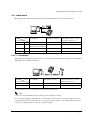
2.2.1 USB . . . . . . . . . . . . . . . . . . . . . . . . . . . . . . . . . . . . . . . . . . . . . . . . . . . . . . . . . . . . . . . . . . . . . . . . . . . .
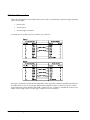
2.3 Serial Connection . . . . . . . . . . . . . . . . . . . . . . . . . . . . . . . . . . . . . . . . . . . . . . . . . . . . . . . . . . . . . . . . . . . .
2.3.1 Stand alone . . . . . . . . . . . . . . . . . . . . . . . . . . . . . . . . . . . . . . . . . . . . . . . . . . . . . . . . . . . . . . . . . . . .
2.3.2 Y-connection . . . . . . . . . . . . . . . . . . . . . . . . . . . . . . . . . . . . . . . . . . . . . . . . . . . . . . . . . . . . . . . . . . .
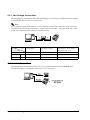
2.3.3 Pass-Through Connections . . . . . . . . . . . . . . . . . . . . . . . . . . . . . . . . . . . . . . . . . . . . . . . . . . . . . . . .
2.4 Parallel Connection . . . . . . . . . . . . . . . . . . . . . . . . . . . . . . . . . . . . . . . . . . . . . . . . . . . . . . . . . . . . . . . . . .
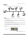
2.5 Ethernet . . . . . . . . . . . . . . . . . . . . . . . . . . . . . . . . . . . . . . . . . . . . . . . . . . . . . . . . . . . . . . . . . . . . . . . . . . . .
2-1
2-1
2-1
2-3
2-3
2-4
2-4
2-4
2-4
2-4
2-5
2-5
2-6
2-7
2-7
2-8
2-8
2-9
xii
Rev. E
TM-H6000III Technical Reference Guide
Chapter 3 Setup
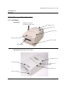
3.1 Part Name and Basic Operation . . . . . . . . . . . . . . . . . . . . . . . . . . . . . . . . . . . . . . . . . . . . . . . . . . . . . . . .
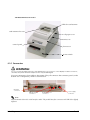
3.1.1 Part Names . . . . . . . . . . . . . . . . . . . . . . . . . . . . . . . . . . . . . . . . . . . . . . . . . . . . . . . . . . . . . . . . . . . . .
3.1.2 Connectors . . . . . . . . . . . . . . . . . . . . . . . . . . . . . . . . . . . . . . . . . . . . . . . . . . . . . . . . . . . . . . . . . . . . .
3.1.2.1 Important Installation Notes . . . . . . . . . . . . . . . . . . . . . . . . . . . . . . . . . . . . . . . . . . . . . . . . . .
3.1.3 The Control Panel . . . . . . . . . . . . . . . . . . . . . . . . . . . . . . . . . . . . . . . . . . . . . . . . . . . . . . . . . . . . . . .
3.1.3.1 LED . . . . . . . . . . . . . . . . . . . . . . . . . . . . . . . . . . . . . . . . . . . . . . . . . . . . . . . . . . . . . . . . . . . . . . .
3.1.3.2 LEDs on the Card panel . . . . . . . . . . . . . . . . . . . . . . . . . . . . . . . . . . . . . . . . . . . . . . . . . . . . .
3.1.3.3 Control Panel Buttons . . . . . . . . . . . . . . . . . . . . . . . . . . . . . . . . . . . . . . . . . . . . . . . . . . . . . . .
3.1.4 Validation paper handling (Option) . . . . . . . . . . . . . . . . . . . . . . . . . . . . . . . . . . . . . . . . . . . . . . . .
3.1.5 Card insertion method (Option) . . . . . . . . . . . . . . . . . . . . . . . . . . . . . . . . . . . . . . . . . . . . . . . . . . .
3.2 Setup Flow . . . . . . . . . . . . . . . . . . . . . . . . . . . . . . . . . . . . . . . . . . . . . . . . . . . . . . . . . . . . . . . . . . . . . . . . . . .
3.3 Printer setup . . . . . . . . . . . . . . . . . . . . . . . . . . . . . . . . . . . . . . . . . . . . . . . . . . . . . . . . . . . . . . . . . . . . . . . . .
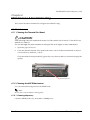
3.3.1 Connecting the Power Supply Unit (PS-180) . . . . . . . . . . . . . . . . . . . . . . . . . . . . . . . . . . . . . . . . . .
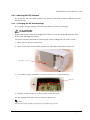
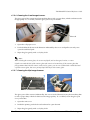
3.3.2 Installing or Replacing the Ribbon Cassette . . . . . . . . . . . . . . . . . . . . . . . . . . . . . . . . . . . . . . . . .
3.3.3 Installing or Replacing the Endorsement Ribbon Cassette . . . . . . . . . . . . . . . . . . . . . . . . . . . . .
3.3.4 Installing or Replacing the Paper Roll . . . . . . . . . . . . . . . . . . . . . . . . . . . . . . . . . . . . . . . . . . . . . . .
3.3.5 Connecting the Printer to the Host PC / POS Terminal . . . . . . . . . . . . . . . . . . . . . . . . . . . . . . . . .
3.3.5.1 Serial interface model . . . . . . . . . . . . . . . . . . . . . . . . . . . . . . . . . . . . . . . . . . . . . . . . . . . . . . .
3.3.5.2 Parallel Interface Models . . . . . . . . . . . . . . . . . . . . . . . . . . . . . . . . . . . . . . . . . . . . . . . . . . . .
3.3.5.3 USB Interface Models . . . . . . . . . . . . . . . . . . . . . . . . . . . . . . . . . . . . . . . . . . . . . . . . . . . . . . .
3.3.5.4 Connecting a Drawer . . . . . . . . . . . . . . . . . . . . . . . . . . . . . . . . . . . . . . . . . . . . . . . . . . . . . . .
3.4 Customizing . . . . . . . . . . . . . . . . . . . . . . . . . . . . . . . . . . . . . . . . . . . . . . . . . . . . . . . . . . . . . . . . . . . . . . . . .
3.4.1 How to Confirm Current Settings . . . . . . . . . . . . . . . . . . . . . . . . . . . . . . . . . . . . . . . . . . . . . . . . . . .
3.4.2 Adjusting the Roll Paper Near End Detector . . . . . . . . . . . . . . . . . . . . . . . . . . . . . . . . . . . . . . . . .
3.4.3 Adjusting the DIP Switches . . . . . . . . . . . . . . . . . . . . . . . . . . . . . . . . . . . . . . . . . . . . . . . . . . . . . . . .
3.4.3.1 Changing the DIP Switch Settings . . . . . . . . . . . . . . . . . . . . . . . . . . . . . . . . . . . . . . . . . . . . .
3.4.3.2 Serial interface model . . . . . . . . . . . . . . . . . . . . . . . . . . . . . . . . . . . . . . . . . . . . . . . . . . . . . . .
3.4.3.3 Parallel / Ethernet interface model . . . . . . . . . . . . . . . . . . . . . . . . . . . . . . . . . . . . . . . . . . .
3.4.3.4 USB interface model . . . . . . . . . . . . . . . . . . . . . . . . . . . . . . . . . . . . . . . . . . . . . . . . . . . . . . .
3.4.3.5 When Using Original Paper . . . . . . . . . . . . . . . . . . . . . . . . . . . . . . . . . . . . . . . . . . . . . . . . . . .
3.4.4 Memory Switches . . . . . . . . . . . . . . . . . . . . . . . . . . . . . . . . . . . . . . . . . . . . . . . . . . . . . . . . . . . . . . . .
3.4.5 How to Use Two-Color Printing . . . . . . . . . . . . . . . . . . . . . . . . . . . . . . . . . . . . . . . . . . . . . . . . . . . . .
3.5 Self Tests . . . . . . . . . . . . . . . . . . . . . . . . . . . . . . . . . . . . . . . . . . . . . . . . . . . . . . . . . . . . . . . . . . . . . . . . . . . .
3.5.1 Running the Self Test on Roll Paper . . . . . . . . . . . . . . . . . . . . . . . . . . . . . . . . . . . . . . . . . . . . . . . . .
3.5.2 Running the Self Test with Slip Paper . . . . . . . . . . . . . . . . . . . . . . . . . . . . . . . . . . . . . . . . . . . . . . . .
3.5.3 Running the Self Test with the Validation paper (Option) . . . . . . . . . . . . . . . . . . . . . . . . . . . . . .
3.5.4 Running the Self Test with the Endorsement Function (Option) . . . . . . . . . . . . . . . . . . . . . . . . . .
3-1
3-1
3-2
3-3
3-3
3-3
3-4
3-5
3-5
3-6
3-7
3-8
3-8
3-9
3-12
3-13
3-15
3-15
3-16
3-16
3-17
3-18
3-18
3-18
3-19
3-19
3-20
3-21
3-22
3-23
3-23
3-24
3-24
3-24
3-25
3-25
3-25
Chapter 4 Maintenance & Troubleshooting
4.1 Maintenance . . . . . . . . . . . . . . . . . . . . . . . . . . . . . . . . . . . . . . . . . . . . . . . . . . . . . . . . . . . . . . . . . . . . . . . .
4.1.1 Cleaning the Thermal Print Head . . . . . . . . . . . . . . . . . . . . . . . . . . . . . . . . . . . . . . . . . . . . . . . . . .
4.1.2 Cleaning the MICR Mechanism . . . . . . . . . . . . . . . . . . . . . . . . . . . . . . . . . . . . . . . . . . . . . . . . . . . .
4.1.2.1 Cleaning frequency . . . . . . . . . . . . . . . . . . . . . . . . . . . . . . . . . . . . . . . . . . . . . . . . . . . . . . . .
4.1.2.2 Cleaning sheet . . . . . . . . . . . . . . . . . . . . . . . . . . . . . . . . . . . . . . . . . . . . . . . . . . . . . . . . . . . .
4.1.2.3 Cleaning procedure . . . . . . . . . . . . . . . . . . . . . . . . . . . . . . . . . . . . . . . . . . . . . . . . . . . . . . . .
4.1.2.4 Self mode . . . . . . . . . . . . . . . . . . . . . . . . . . . . . . . . . . . . . . . . . . . . . . . . . . . . . . . . . . . . . . . . .
4.1.2.5 Command mode . . . . . . . . . . . . . . . . . . . . . . . . . . . . . . . . . . . . . . . . . . . . . . . . . . . . . . . . . .
4.1.2.6 Cleaning the Card Image Scanner . . . . . . . . . . . . . . . . . . . . . . . . . . . . . . . . . . . . . . . . . . .
4.1.2.7 Cleaning the Slip Image Scanner . . . . . . . . . . . . . . . . . . . . . . . . . . . . . . . . . . . . . . . . . . . . .
4.2 Troubleshooting . . . . . . . . . . . . . . . . . . . . . . . . . . . . . . . . . . . . . . . . . . . . . . . . . . . . . . . . . . . . . . . . . . . . . .
4.2.1 Removing a Paper Jam . . . . . . . . . . . . . . . . . . . . . . . . . . . . . . . . . . . . . . . . . . . . . . . . . . . . . . . . . .
4.2.2 Autocutter Jam . . . . . . . . . . . . . . . . . . . . . . . . . . . . . . . . . . . . . . . . . . . . . . . . . . . . . . . . . . . . . . . . .
4.2.3 Card Jam . . . . . . . . . . . . . . . . . . . . . . . . . . . . . . . . . . . . . . . . . . . . . . . . . . . . . . . . . . . . . . . . . . . . . .
4.2.4 LED Blinking Pattern . . . . . . . . . . . . . . . . . . . . . . . . . . . . . . . . . . . . . . . . . . . . . . . . . . . . . . . . . . . . . .
4.2.4.1 Error Types . . . . . . . . . . . . . . . . . . . . . . . . . . . . . . . . . . . . . . . . . . . . . . . . . . . . . . . . . . . . . . . . .
4.2.5 Blinking pattern of Card panel LED . . . . . . . . . . . . . . . . . . . . . . . . . . . . . . . . . . . . . . . . . . . . . . . . .
4.2.6 Printer prints “?“ or Incorrect Data With Serial Interface . . . . . . . . . . . . . . . . . . . . . . . . . . . . . . . .
4.2.7 Hexadecimal Dump . . . . . . . . . . . . . . . . . . . . . . . . . . . . . . . . . . . . . . . . . . . . . . . . . . . . . . . . . . . . .
Rev. E
4-1
4-1
4-1
4-1
4-2
4-2
4-2
4-2
4-3
4-3
4-4
4-4
4-5
4-5
4-6
4-6
4-7
4-8
4-8
xiii
Chapter 5 Application Development Information for UPOS
5.1 Single-pass processing . . . . . . . . . . . . . . . . . . . . . . . . . . . . . . . . . . . . . . . . . . . . . . . . . . . . . . . . . . . . . . . . 5-1
5.1.1 Recommended Flow . . . . . . . . . . . . . . . . . . . . . . . . . . . . . . . . . . . . . . . . . . . . . . . . . . . . . . . . . . . . 5-2
5.1.2 Sample Program . . . . . . . . . . . . . . . . . . . . . . . . . . . . . . . . . . . . . . . . . . . . . . . . . . . . . . . . . . . . . . . . 5-3
Chapter 6 Application Development Information for APD
Chapter 7 Application Development for Image Scanner
7.1 The flow of single pass processing . . . . . . . . . . . . . . . . . . . . . . . . . . . . . . . . . . . . . . . . . . . . . . . . . . . . . . .
7.2 Sharpness Function . . . . . . . . . . . . . . . . . . . . . . . . . . . . . . . . . . . . . . . . . . . . . . . . . . . . . . . . . . . . . . . . . . .
7.2.1 What is sharpness? . . . . . . . . . . . . . . . . . . . . . . . . . . . . . . . . . . . . . . . . . . . . . . . . . . . . . . . . . . . . . .
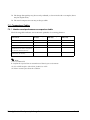
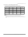
7.3 Comparison Tables . . . . . . . . . . . . . . . . . . . . . . . . . . . . . . . . . . . . . . . . . . . . . . . . . . . . . . . . . . . . . . . . . . .
7.3.1 Interface and performance comparison table . . . . . . . . . . . . . . . . . . . . . . . . . . . . . . . . . . . . . .
7.3.2 Function vs. control method comparison table . . . . . . . . . . . . . . . . . . . . . . . . . . . . . . . . . . . . . .
7-1
7-3
7-3
7-4
7-4
7-5
Appendix A Character Code Tables
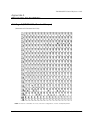
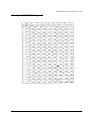
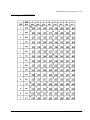
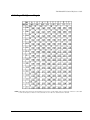
A.1 Page 0 (PC437: USA, Standard Europe) . . . . . . . . . . . . . . . . . . . . . . . . . . . . . . . . . . . . . . . . . . . . . . . . . .
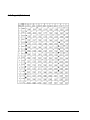
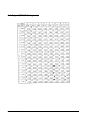
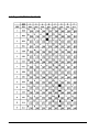
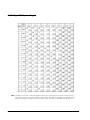
A.2 Page 1 (Katakana) . . . . . . . . . . . . . . . . . . . . . . . . . . . . . . . . . . . . . . . . . . . . . . . . . . . . . . . . . . . . . . . . . . .
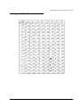
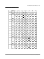
A.3 Page 2 (PC850: Multilingual) . . . . . . . . . . . . . . . . . . . . . . . . . . . . . . . . . . . . . . . . . . . . . . . . . . . . . . . . . . .
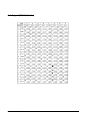
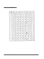
A.4 Page 3 (PC860: Portuguese) . . . . . . . . . . . . . . . . . . . . . . . . . . . . . . . . . . . . . . . . . . . . . . . . . . . . . . . . . . .
A.5 Page 4 (PC863: Canadian-French) . . . . . . . . . . . . . . . . . . . . . . . . . . . . . . . . . . . . . . . . . . . . . . . . . . . . .
A.6 Page 5 (PC865: Nordic) . . . . . . . . . . . . . . . . . . . . . . . . . . . . . . . . . . . . . . . . . . . . . . . . . . . . . . . . . . . . . . .
A.7 Page 16 (WPC1252) . . . . . . . . . . . . . . . . . . . . . . . . . . . . . . . . . . . . . . . . . . . . . . . . . . . . . . . . . . . . . . . . . .
A.8 Page 17 (PC866: Cyrillic2) . . . . . . . . . . . . . . . . . . . . . . . . . . . . . . . . . . . . . . . . . . . . . . . . . . . . . . . . . . . . .
A.9 Page 18 (PC852: Latin2) . . . . . . . . . . . . . . . . . . . . . . . . . . . . . . . . . . . . . . . . . . . . . . . . . . . . . . . . . . . . . . .
A.10 Page 19 (PC858: Euro) . . . . . . . . . . . . . . . . . . . . . . . . . . . . . . . . . . . . . . . . . . . . . . . . . . . . . . . . . . . . . . .
A.11 Page 254 (Space Page) . . . . . . . . . . . . . . . . . . . . . . . . . . . . . . . . . . . . . . . . . . . . . . . . . . . . . . . . . . . . . .
A.12 Page 255 (Space Page) . . . . . . . . . . . . . . . . . . . . . . . . . . . . . . . . . . . . . . . . . . . . . . . . . . . . . . . . . . . . . .
A.13 International Character Sets . . . . . . . . . . . . . . . . . . . . . . . . . . . . . . . . . . . . . . . . . . . . . . . . . . . . . . . . . .
A-1
A-2
A-3
A-4
A-5
A-6
A-7
A-8
A-9
A-10
A-11
A-12
A-13
Appendix B Power Supply Specifications
B.1 PS-180 (Energy Saving Power Supply Unit) . . . . . . . . . . . . . . . . . . . . . . . . . . . . . . . . . . . . . . . . . . . . . . . .
B.1.1 Electrical Characteristics . . . . . . . . . . . . . . . . . . . . . . . . . . . . . . . . . . . . . . . . . . . . . . . . . . . . . . . . .
B.1.2 Case Specifications . . . . . . . . . . . . . . . . . . . . . . . . . . . . . . . . . . . . . . . . . . . . . . . . . . . . . . . . . . . . .
Material . . . . . . . . . . . . . . . . . . . . . . . . . . . . . . . . . . . . . . . . . . . . . . . . . . . . . . . . . . . . . . . . . . . . . . . .
B.1.3 AC Cable Selection . . . . . . . . . . . . . . . . . . . . . . . . . . . . . . . . . . . . . . . . . . . . . . . . . . . . . . . . . . . . .
B-1
B-1
B-2
B-2
B-2
Appendix C FAQ
C.1 Serial Interface . . . . . . . . . . . . . . . . . . . . . . . . . . . . . . . . . . . . . . . . . . . . . . . . . . . . . . . . . . . . . . . . . . . . . .
C.1.1 The printer does not operate correctly or the printer does not print. What should I do? . . . .
C.1.2 Printing takes a long time. What should I do? . . . . . . . . . . . . . . . . . . . . . . . . . . . . . . . . . . . . . . . .
C.1.3 The Customer Display does not operate correctly. What should I do? . . . . . . . . . . . . . . . . . . .
C.1.4 What is the cable wiring for connecting a printer and a host PC with a serial interface? . . .
C.1.5 How many printers can be connected? . . . . . . . . . . . . . . . . . . . . . . . . . . . . . . . . . . . . . . . . . . . .
C.1.6 Is there limitation for the length of a cable? . . . . . . . . . . . . . . . . . . . . . . . . . . . . . . . . . . . . . . . . .
C.2 Parallel Interface . . . . . . . . . . . . . . . . . . . . . . . . . . . . . . . . . . . . . . . . . . . . . . . . . . . . . . . . . . . . . . . . . . . .
C.2.1 The printer does not operate correctly or the printer does not print. What should I do? . . . .
C.2.2 What is the cable wiring for connecting the printer
and the host PC with a parallel interface? . . . . . . . . . . . . . . . . . . . . . . . . . . . . . . . . . . . . . . . . . .
C.2.3 How many printers can be connected? . . . . . . . . . . . . . . . . . . . . . . . . . . . . . . . . . . . . . . . . . . . .
C.2.4 Is there limitation for the length of a cable? . . . . . . . . . . . . . . . . . . . . . . . . . . . . . . . . . . . . . . . . .
C.2.5 Can a Customer Display be connected? . . . . . . . . . . . . . . . . . . . . . . . . . . . . . . . . . . . . . . . . . . .
C.2.6 When I turned on the printer with a parallel interface and then turned on the PC,
the message “New hardware has been found.” appeared
and the device “EPSON TM-Px.xx” was detected. What is “EPSON TM-Px.xx”? . . . . . . . . . . . .
C.2.7 Printer cannot be reset. What should I do? . . . . . . . . . . . . . . . . . . . . . . . . . . . . . . . . . . . . . . . . . .
xiv
C-1
C-1
C-1
C-1
C-2
C-3
C-3
C-4
C-4
C-4
C-5
C-6
C-6
C-6
C-6
Rev. E
TM-H6000III Technical Reference Guide
C.3 USB Interface . . . . . . . . . . . . . . . . . . . . . . . . . . . . . . . . . . . . . . . . . . . . . . . . . . . . . . . . . . . . . . . . . . . . . . . .
C.3.1 The TM printer does not operate. What should I do? . . . . . . . . . . . . . . . . . . . . . . . . . . . . . . . . . .
C.3.2 The Customer Display does not operate correctly. What should I do? . . . . . . . . . . . . . . . . . . .
C.3.3 What should be considered for a Customer Display connection? . . . . . . . . . . . . . . . . . . . . . .
C.3.4 Can a Customer Display be connected? . . . . . . . . . . . . . . . . . . . . . . . . . . . . . . . . . . . . . . . . . . .
C-6
C-6
C-7
C-7
C-8
Appendix D Comparison Table
Rev. E
xv
xvi
Rev. E
TM-H6000III Technical Reference Guide
Chapter 1
General Information
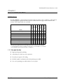
1.1 Features
TM-H6000III (Receipt and Slip printers) *
✔
✔
TM-H6000III with MICR
✔
✔
TM-H6000III with Endorsement
✔
✔
TM-H6000III with Validation
✔
✔
TM-H6000III with Endorsement and MICR
✔
✔
✔
TM-H6000III with Validation and MICR
✔
✔
✔
TM-H6000III with Image Scanner
✔
✔
✔
✔
✔
TM-H6000III Photo-ID Model with Image Scanner
✔
✔
✔
✔
✔
Photo-ID
Validation
Image Scanner
Model
Endorsement
MICR
Slip
Receipt
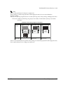
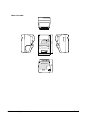
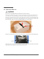
The TM-H6000III is a high-quality POS printer that can print on slip, validation, endorsement
and receipt paper (paper roll). There are also models with an image scanner and Photo-ID
scanner. Following models are available.
✔
✔
✔
✔
✔
✔
* Models with Simplified Chinese and Traditional Chinese characters are available.
For the detailed information regarding models, please contact EPSON or your dealer.
(See “Related Software and Documents” on page vi.)
1.1.1 Receipt Section
❏ High-speed graphic printing
❏ Autocutter provides easy user operation
❏ Easy drop-in paper roll loading
❏ PDF417 symbols (2-dimensional code) printing is possible
❏ Two-color printing is possible with two-color paper
Rev. E
General Information 1-1
1.1.2 Slip/ Validation/ Endorsement Section (Validation/ Endorsement option)
❏ High throughput using bidirectional, minimum distance printing.
❏ Page mode for flexibility in printing formats
❏ Two ways are available for slip paper loading (drop- in for validation, and front insertion for
slip)
❏ An endorsement printer (E/P) that enables single-pass high speed printing of
endorsements.(The endorsement printer cannot be installed on a printer with the validation
function.)
❏ Line spacing cannot be changed for an endorsement printer.
1.1.3 MICR section (Option)
❏ A Magnetic Ink Character Recognition (MICR) reader that enables the printer to perform
consecutive reading and processing of MICR characters
1.1.4 Image scanner section (Option)
❏ The sharpness function is supported.
❏ Single-pass processing for checks eliminates the need to reverse the check paper for printing
an endorsement.(The validation function model doesn't have an endorsement printer.)
1.1.5 Card image scanner section (Option)
❏ Card can be scanned as an image based on ISO/IEC7810
❏ Operation is as easy as using a card in an ATM.
1.1.6 Others
❏ Small footprint and simple design
❏ EPSON customer display modules (DM-D***) can be connected (available only for the serial
interface model)
❏ NV (Non-volatile) bit image buffer (384 KB) *
❏ NV (Non-volatile) user memory (1 KB) *
❏ A counter function that allows checking the printer by remote maintenance
❏ Several interface models (USB, RS-232, bidirectional parallel, Ethernet) are supported
* The memory size can be set by ESC/POS command.
1.1.7 About control method
❏ Command protocol based on the ECS/POS® Proprietary Command System.
❏ Automatic Status Back (ASB) function that automatically transmits changes in the printer
status
❏ Windows® printer driver is provided. (Advanced Printer Driver, OPOS and JavaPOS)
1-2 General Information
Rev. E
TM-H6000III Technical Reference Guide
1.2 Product Structure
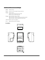
1.2.1 Standard Parts Included with the Printer
This printer is packed with the materials listed below.
❏ Printer
❏ User’s Manual
❏ Roll paper (diameter 40 mm {1.57"}) 1 roll
❏ Power switch cover (using this cover enables you to prevent accidental turning off of the
power)
❏ Exclusive ribbon cassette ERC-32(B)
❏ Endorsement ribbon cassette (only for printers equipped with the optional endorsement
print mechanism)
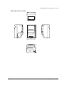
1.2.2 Options
The options for this printer are provided as below.
❏ EPSON power supply unit, PS-180
❏ Direct connection customer display and special stand DM-D500+DP502, DM-D110+DP502,
DM-D210+DP502 (available only for the serial interface model)
❏ Special tray (PT-6000, DPR-6000, TA-6000)
1.3 Consumables
1.3.1 Roll paper
Paper width:
79.5 ± 0.5 mm {3.13" ± 0.02"}
Paper roll size:
Roll diameter: Maximum 83 mm {3.27"}
Take-up paper roll width: 80+0.5/-1.0 mm {3.15+0.02/-0.04"}
NOTE:
See “Paper Specifications” (page 1-6) for details.
1.3.2 Ribbons
This printer needs a ribbon cassette to print on slip/validation(and endorsement). We provide 2
ribbon cassettes:
❏ EPSON ribbon cassette, ERC-32 (B) (Life: 4,000,000 characters / Color: Black) for slip/
validation.
❏ EPSON ribbon cassette ERC-41 (B) (Life: 800,000 characters) (for the optional endorsement
print mechanism)
Rev. E
General Information 1-3
1.4 Printing and Paper Specifications
1.4.1 Receipt Section
Printing method:
Thermal line printing
Dot density:
180 dpi × 180 dpi [the number of dots per 25.4 mm {1"}]
Printing direction:
Unidirectional with friction feed
Printing width:
72 mm {2.83"}, 512 dot positions
Paper width:
79.5 ± 0.5mm {3.13 ± 0.02"}
Characters per line:
42 (font A, default) 56 (font B)
Character spacing:
0.28 mm {.01"} (2 dots) (font A, default)
0.28 mm {.01"} (2 dots) (font B)
Programmable by control command.
Print speed:
Normal: 63 lps maximum (computed value for 1/8" feed)
200 mm/s {7.9"/s} maximum
(at 24 V, density level 2) (lps: lines per second)
Ladder barcode/2-dimensional code printing:
118 mm/s {4.65"/s} maximum
Two-color print mode:
78 mm/s {3.07"/s} maximum
(at 24V, density level 2)
Paper feed speed:
Approximately 200 mm/s {7.9"/s} continuous feeding
Line spacing (default): 4.23 mm {1/6"}, programmable by control commands.
Number of characters: Alphanumeric characters: 95
International characters:
37
Extended graphics: 128 × 11 pages (including one space page)
Multilingual character model supports printing with one of the
following character sets:
Simplified Chinese (GB2312): 7580
Traditional Chinese (Big 5): 13494
Character structure:
Font A: 12 × 24 (including 2-dot spacing in horizontal)
Font B: 9 × 17 (including 2-dot spacing in horizontal)
Kanji: 24 × 24
Font A is the default
1-4 General Information
Rev. E
TM-H6000III Technical Reference Guide
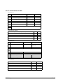
Character size, characters per line
Standard
W x H in mm
{inches}
Double-height
CPL
W x H in mm
{inches}
Double-width/
Double-height
Double-width
CPL
W x H in mm
{inches}
CPL
W x H in mm
{inches}
CPL
Font A
12 x 24
1.41 x 3.39
{.06 x .13"}
42
1.41 x 6.77
{.06 x .27"}
42
2.82 x 3.39
{.11 x .13"}
21
2.82 x 6.77
{.11 x .27"}
21
Font B
9 x 17
0.99 x 2.40
{.04 x .09"}
56
0.99 x 4.80
{.04 x .19"}
56
1.98 x 2.40
{.08 x .09"}
28
1.98 x 4.80
{.08 x .19"}
28
Kanji
12 x 24
3.39 x 3.39
{.13 x .13"}
21
3.39 x 6.77
{.13 x .27"}
42
6.77 x 3.39
{.27 x .13"}
10
6.77 x 6.77
{.11 x .27"}
21
*
CPL = characters per line
*
Space between characters is not included
*
Characters can be scaled up to 64 times the standard size.
*
When using Font B in a font mode such as emphasized mode, some words may be hard to read. Check the font
mode in advance when using Font B.
1.4.1.1 Autocutter
Partial cut: Cutting with one point left uncut
NOTE:
1. To prevent dot displacement, after cutting, feed paper approximately 1 mm (14/360 inches) or more before
printing.
2. If the printer is stopped, you must feed paper more than 40 mm {1.57"} before cutting.
1.4.1.2 Paper Roll Supply Device Section
Supply method:
Near-end sensor:
Paper roll end detection:
Drop-in paper roll
Micro switch
Paper roll spool diameter:
Inside: 12 mm {.47"}
Outside: 18 mm {.71"}
Near-end adjustment: Adjusting screw
Remaining amount: Fixed position
#1 approximately 23 mm {0.9"}
#2 approximately 27 mm {1.06"}
(The adjusting screw has two positions.)
See Chapter 5.
Micro switch
NOTE: You can use the ESC/POS command to stop printing upon detection of a paper near-end.
Rev. E
General Information 1-5
1.4.1.3 Paper Specifications
Paper type:
Specified thermal paper
Form:
Paper roll
Paper width:
79.5 ± 0.5 mm {3.13" ± 0.02"}
Paper roll size:
Roll diameter: Maximum 83 mm {3.27"}
Take-up paper roll width: 80+0.5/-1.0 mm {3.15+0.02/-0.04"}
Specified paper:
Specified thermal roll paper, NTP080-80
In Japan: Nakagawa Mfg. Co., Ltd.
In USA: Nakagawa Mfg. (USA) Inc.
In Europe: Nakagawa Mfg. (Europe) GmbH
In Southeast Asia: N.A.K. Mfg. (Malaysia) SDN BHD
[Original paper: TF50KS-E (paper thickness: 65µm) Nippon
Paper Industries Co.,Ltd.]
The following paper can be used instead of the specified paper
above:
Original paper: PD 160R (paper thickness: 75µm) (Oji Paper
Mfg. Co. Ltd.)
Original paper: AF50KS-E (paper thickness: 65µm) (Jujo
Thermal Oy (Finland))
Original paper: P350(F380) (paper thickness: 62µm) (Kanzaki
Specialty Papers, Inc. (U.S.A.))
Original paper: P310 (paper thickness: 58µm) (Kanzaki
Specialty Papers, Inc. (U.S.A.))
Original paper: P300 (paper thickness: 56µm) (Kanzaki
Specialty Papers, Inc. (U.S.A.))
Original paper: F5041 (paper thickness: 60µm) (Mitsubishi
HiTec Paper Flensburg GmbH (Germany))
Specified two-color thermal roll paper, ENTPB080080
In Japan: Nakagawa Mfg. Co., Ltd.
In USA: Nakagawa Mfg. (USA) Inc.
In Europe: Nakagawa Mfg. (Europe) GmbH
In Southeast Asia: N.A.K. Mfg. (Malaysia) SDN BHD
[Original paper: PD750R (paper thickness: 75µm) Oji Paper
Mfg. Co.,Ltd.] Paper roll which is made of the original paper
PD750R can be used.
NOTE: With some printing patterns, the previous print color may not be
cleared. The printer’s reliability when two-color thermal paper is used differs
from the reliability when monochrome paper is used.
Paper roll spool diameter:
Inside: 12 mm {.47"} Outside: 18 mm {.71"}
NOTE:
Paper must not be pasted to the paper roll spool.
When paper other than that specified is used, the thermal print head may be worn out.Be sure to use the
specified paper.
Depending on each paper specification, it is recommended to set the DIP switch.
(See “When Using Original Paper” on page 3-23.)
1-6 General Information
Rev. E
TM-H6000III Technical Reference Guide
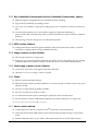
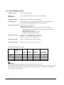
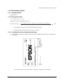
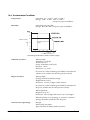
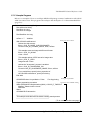
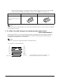
1.4.1.4 Printable Area
The printable area of a paper roll with a width of 79.5 ± 0.5 mm (3.13" ± 0.02") is 72.2 ± 0.2 mm
(2.84" ± 0.008") (512 dots), and the space on the right and left sides are approximately 3.7 ±
2 mm (0.15" ± 0.079").
72.2
3.7 2
79.5 0.5
Printable area for paper roll
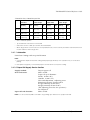
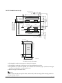
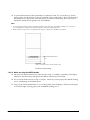
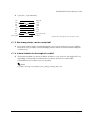
1.4.1.5 Printing and Cutting Positions
Manual cutter position
Approx. 24
Autocutter head position
Approx. 10
Paper feed direction
Center of the print dotline
[Units:mm(All the numerical values ae typical.)]
Printing and cutting positions
NOTE: Numeric values used here are typical values; the values may vary slightly as a result of paper slack or
variations in the paper. Take this into account when setting the cutting position of the autocutter.
Rev. E
General Information 1-7
1.4.2 Slip/ Validation Section
Printing method:
Serial impact dot matrix
Head wire
configuration:
9-pin vertical line, 0.353 mm {1/72-inch} wire pitch
Printing direction:
Bidirectional, minimum distance printing
Printing speed:
Approximately 5.7 LPS (printing 40 columns per line with 17.8 CPI
when the head energizing time is set to normal mode.)
Number of characters: Alphanumeric characters: 95
International characters: 37
Extended graphics: 128 × 12 pages (including two space pages)
Multilingual character model supports printing with one of the
following character sets:
Simplified Chinese (GB2312): 7580
Traditional Chinese (Big 5): 13494
Character structure:
Font A: 5 × 9 (total 270 dots horizontally)
Font B: 7 × 9 (total 540 half dots horizontally)
Kanji: 16 × 16 (two-pass printing font)
Characters per line:
Refer to “Character size and print speed.”
Characters per inch:
Refer to “Character size and print speed.”
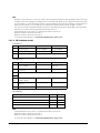
Character size and print speed
Character
structure
(horizontal dots
×
vertical dots)
Character
spacing
Characters
per inch
Characters
per line
Character size
(width× height)
A
(default)
5× 9
1 dot
13.3
45
1.56 × 3.1 mm
B
7× 9
2 half-dots
17.8
60
1.24 × 3.1 mm
Kanji
16 × 16
2 half-dots
8.9
30
2.7 × 2.9 mm
Font
Note:
TM-H6000III (Receipt and Slip printers) has models with Kanji characters.
Kanji character spacing by default setting is 2 half dots. (Kanji character spacing can be changed by ESC/
POS command.) Printing speed for Kanji characters shown in table above is in the case of full column
printing with two-pass printing.
1-8 General Information
Rev. E
TM-H6000III Technical Reference Guide
1.4.2.1 Paper Specifications
1. Cut sheet
Paper type: Normal paper, pressure-sensitive paper, carbon copy paper
Paper size: 68 - 230 mm (W) × 68 - 297 mm (L) {2.7 - 9.1"(W) × 2.7 - 11.7"(L)}
NOTE: The minimum size is 68mm × 152mm {2.7" × 6.0"}
Copy capability and paper thickness:
•
Normal paper (single-ply):0.09 to 0.2 mm {0.0035 to 0.0079"}
•
Carbon copy paper
combination:4 sheets maximum
•
Backing paper:
0.07 to 0.12 mm {0.0028 to 0.0047"}
Copy and original:
0.04 to 0.07 mm {0.0016 to 0.0028"}
Carbon paper:
Approximately 0.035 mm {0.0014"}
Total thickness:
0.09 to 0.31 mm {0.0035 to 0.0122"}
Example: one original + 2 copies,
Original paper:
0.04 mm
Carbon paper:
0.07 mm (0.035 mm × 2 sheets)
Copy paper:
0.04 mm
Backing paper:
0.07 mm
Total thickness:
0.22 mm {0.0087 "}
Ambient temperature and copy capability:
Copy capability is greatly influenced by the ambient temperature, so printing must be
performed under the conditions described in the table below.
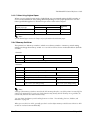
Relationship between ambient temperature and number of copies
Number of copies
Ambient temperature
Original + 3 copies
10 to 40 °C {50 to 104°F}
Original + 1 copy
5 to 45 °C {41 to 113 °F}
Rev. E
General Information 1-9
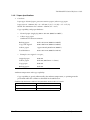
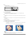
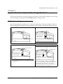
2. Notes on slip/validation paper
•
The paper must be flat, without curls or wrinkles, especially at the top edges.
Otherwise, the paper may rub against the ribbon and become dirty.
•
Insert a validation from the upper side in the validation entrance of the case opening. If
the validation is inserted sliding from the left to the right, the print position may be
incorrect since the paper can be crooked or the validation sensor can detect incorrectly.
•
There must be no glue on the bottom edge of paper. Choose paper carefully when the
glue is on the right or top edge, since paper feeding and insertion are affected by gluing
conditions (e.g., glue quality, method, and length) and glue location (refer to the figure
below). Be especially careful when paper is wide and has the glue on the left edge, since
skew may occur.
OK to use
Paper feed
direction
Do not use
Use carefully
Use carefully
Glued area
Slip (validation) paper glued area
•
Since the slip BOF sensor uses a photo sensor, do not use paper that has holes at the
sensor position, or is translucent.
•
Since the slip TOF sensor and validation sensor use a reflective photo sensor and it
detects from the back of slip paper, do not use paper that has holes or dark portions with
low reflection (less than 40% reflection) at the sensor position.
•
Since the slip paper ejection sensor uses a reflective photo sensor and it detects from the
surface of the paper roll, do not use paper that has holes or dark portions with low
reflection (less than 40% reflection) at the sensor position.
1-10 General Information
Rev. E
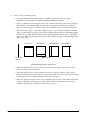
TM-H6000III Technical Reference Guide
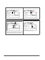
•
Use thinner paper (N30 or equivalent) between the top and bottom sheets of multi-ply
paper. If thick paper is used, the copy capability is lowered.
30
15
20
10
Area where paper holes are
prohibited and reflection rate
for the back on paper should
be 40% or more.
Area where paper holes are
prohibited and reflection rate
for the surface on paper
should be 40% or more.
Paper holes and
translucence prohibited in
this area.
Paper feed direction
[Units: mm (All the numeric values are typical.)]
Prohibited area for slip paper holes and low reflection
: Holes or portions with
low reflection are
prohibited in this area.
Inserting
direction
7mm
20mm
Prohibited area for validation paper holes and low reflection
Rev. E
General Information 1-11
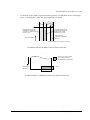
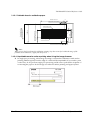
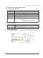
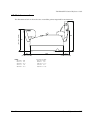
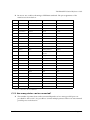
1.4.2.2 Printable Area for slip
Slip ejection sensor position
23.2
5.6
3.1
85.4
56.8
*2Approx. 81.3
(For 461 steps)
Approx. 92.8
16.4
(2)
Paper feeding
roller position
Form stopper position
9
37.8
2
Sub-paper feeding
roller position
60
*4Approx. 114.8
TOF sensor position
(MAX. 651 steps)
Paper insertion direction
Forward paper feed direction
*3
( 8.1 )
The first printing line position
BOF sensor position
4
*5
MIN . 18 . 4
The last printing line position
Form stopper
PRINT
AREA
Paper inserting direction
5
18.4
(Min)
85.4(MAX)
68(Min)
5.6
(Units: mm)
Printable area for slip paper
*2 The length from the form stopper to the tip of the paper.
*3 The length from the tip of the paper to the first printing line position.
*4 The printable area after the slip BOF sensor detects the end of the paper. (The bottom margin
must be considered for a real printable area.)
*5 Bottom margin (calculated value).
Note:
Numeric values used here are typical values; consider this for the user design for the starting position in
the paper feeding direction.
1-12 General Information
Rev. E
TM-H6000III Technical Reference Guide
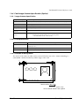
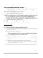
1.4.2.3 Printable Area for validation paper
Printable Area 85.4
5.6
23.2
Validation sensor position
15
71
1.5
18.4
Last printing position
Printable Area 32.8
49.65
29.65
3.1
Print starting position
(20)
8 lines printing for 168 steps
(When approximately 4.23mm (1/6”) feeding pitch)
70 (MIN. 68)
Paper feeding direction
Paper inserting direction
Slip ejection sensor position
Note:
When reverse feed is performed in validation printing, keep the reverse feed within the range of the
printable area. Otherwise, a paper jam away occur.
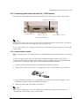
1.4.2.4 Unprintable area for surface printing when Using the Image Scanner
❏ In single-pass processing, when image scanning is executed in combination with surface
printing, 40 mm (typical) from the edge of a check will be unprintable. If you need to print
on that area, do not perform single-pass processing and be sure to perform the sequence of
re-inserting the paper to do the image scan after the surface printing and paper ejection.
Rev. E
General Information 1-13
1.4.3 Endorsement Section (Option)
Printing method:
Shuttle impact dot matrix
Wire pitch approximately 0.353 mm {1/72"}
Head wire
configuration
8 print solenoids in a horizontal line
Characters per line:
40 columns
Print speed:
Approximately 1.9 lps (lps: lines per second)
Number of characters: Alphanumeric characters: 95
International characters:
37
Extended graphics: 128 × 11 pages (including one space page)
Character structure
5 × 7 (total 240 dots horizontally)
Character size
1.1 × 2.42 mm (W × H)
Note:
Character dot spacing can be changed by an ESC/POS command.
An endorsement printer cannot be installed on a printer with the validation function.
Line spacing cannot be changed.
1.4.3.1 Paper Specifications
Cut sheet
Paper type:
Normal paper
Paper size:
68-230 mm (W) × 68-297 mm (L)
{2.7 - 9.1"(W) × 2.7 - 11.7"(L)}
Paper thickness:
Single-ply (copy paper cannot be used) 0.09 mm - 0.2 mm
{0.0035 - 0.0079"}
1-14 General Information
Rev. E
TM-H6000III Technical Reference Guide
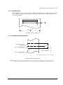
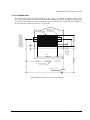
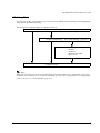
1.4.3.2 Printable Area
The print head consists of 8 print solenoids (A, B, C, D, E, F, G, and H) arranged in a horizontal
line. The print head moves from the left (from the standby position) to the right, printing at 30
positions as each print solenoid is energized, so that one dot line is formed. The total number of
dots per dot line is 240 (30 positions × 8 solenoids).
Slip paper feeding
roller position
2.42
47.8
(152 steps)
Approx. 26.8
3.53
(20 steps)
55.2
6.9
16
Paper feed direction
16.2
Approx. 92.3
MIN. 68
60
Form stopper position
(523 steps)
Paper insertion direction
Endorsement printing
4
BOF sensor position
E/P printable area (for endorsement printing)
Rev. E
General Information 1-15
1.4.3.3 Notes on Using the Endorsement Print Mechanism
❏ The endorsement print mechanism (abbreviated as E/P) enables printing of endorsements
as part of a sequence that is automatically processed: MICR reading, printing an
endorsement on the back side of a personal check, and printing on the surface of it. Once the
end of the paper exceeds the E/P print head position, reverse paper feeding to the front side
is not possible.
❏ When the endorsement printing is executed after a MICR reading, the printer feeds the
paper forward automatically after receiving a command to print the endorsement; then the
printer starts printing up to approximately 7.0 mm {0.28"} from the end of the check paper
by using reverse paper feeding.
❏ Since the E/P printing format is assumed to print an endorsement on a U.S. personal check,
the print begins on the back side of the paper. (As viewed from the front of the printer, the
endorsement printing characters are upside down.)
❏ The printing sequence for slip paper is different, depending on whether an endorsement
print mechanism is installed. That is, when the E/P is installed, once the printing exceeds
the E/P printable area and the slip paper is fed forward, reverse paper feeding must be
prohibited. Consider this when developing application programs.
❏ The E/P printing must be not performed on copy paper. Otherwise, a paper jam may occur
or the E/P may be broken. Because E/P printing feeds the paper in a reverse paper feed
direction, the paper may be wrinkled.
❏ In some case paper feeding may not be accurate when E/P printing is performed on check
paper. This may depend on the width of the check paper. Therefore, it is recommended for
the user to check in advance whether the check paper prints correctly or not.
1-16 General Information
Rev. E
TM-H6000III Technical Reference Guide
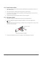
1.4.4 MICR Reader (Option)
1.4.4.1 Reading method
Magnetic bias
1.4.4.2 Recognition rating
98% or more (at 25 ° C, 77 ° F)
Recognition rating is defined as follows
Recognition rationg (%) =
Total number of checks - (number of sheets misread or not identified.)
Total number of checks
•
Check paper used for test is EPSON standard check paper.
•
Checks must be flat, without curls, folds, or wrinkles.
100
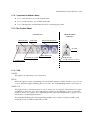
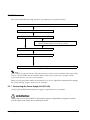
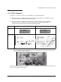
1.4.4.3 Inserting direction and endorsement printing
❏ Insert the check with the surface printed with the magnetic ink upward, following the slip
side guide.
Area of personal check where MICR character recognition is impossible
Rev. E
General Information 1-17
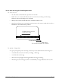
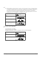
❏ To print endorsements in the specified area (within 38.1 mm {1.5”} from the top), set the
print position for the last line so that it is printed at least 3 mm {0.118”} above the bottom of
the printable area (Especially when the printer is used near the display device, the user is
required to check the recognition rate of the MICR).
NOTE:
1. Do not install the printer near any magnetic fields, because this may cause MICR reading errors. (Be sure to
check the MICR recognition rate when the printer is used near a display device.)
2. MICR characters may not be recognized when impact or vibration is applied to the printer.
Specified printing aria
38.1
[Units : mm (All numeric values are typical.)]
Endorsement printing
1.4.4.4 Notes on using the MICR reader
❏ The personal checks must be flat, without curls, folds, or wrinkles (especially at the edges).
Otherwise, the check may rub against the ribbon and become ink-stained.
❏ Do not insert checks that have clips or staples. These may cause paper jams, MICR reading
errors, and damage to the MICR head.
❏ Let go of the check immediately as soon as the printer starts feeding it. Otherwise, the paper
is not fed straight, causing paper jams and MICR reading errors.
1-18 General Information
Rev. E
TM-H6000III Technical Reference Guide
1.4.5 Slip Image Scanner Specification (Option)
1.4.5.1 Image Scanner Specification
Image scanner type
Contact Image Sensor (CIS)
Resolution
200 dpi (H) × 200 dpi (V) [dpi: dots per inch (number of dots per 25.4 mm {1"})
Gradation
Bi-tonal (black/white) or 256-level gray scale are selectable with a command.
Image scanning width
Width: 100 mm (typical)
Image scanning speed
120 mm/s
Data compression
method
With bi-tonal: CCITT/group4
With gray scale: JPEG
Data transmission
format
With bi-tonal: TIFF (If the data is transmitted without compressing data,
raw data or BMP format.)
With gray scale: JFIF (JPEG format)
(If the data is transmitted without compressing data,
raw data, BMP format or TIFF format.)
1.4.5.2 Paper Specification
Paper type
Normal paper
Paper dimension
68 to 100 × 152 to 230 mm (W × L) {2.7 ∼3.94" × 5.98 ∼ 9.06"}
Minimum: 68 × 152 mm {2.7 ∼6.0"}
Paper thickness
0.09 to 0.2 mm {0.0035 ∼ 0.0079"} (single-ply)
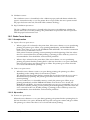
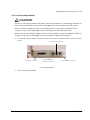
1.4.5.3 Image Readable Area
There is possibility that the areas a, b, and c shown in the illustration below may not be scanned.
Image scanning
width: 100 mm (typical)
c = MAX 2mm
Check insertion direction
Rev. E
General Information 1-19
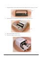
1.4.5.4 Image Data Quality
❏ Be sure to include the pre-scanning step when scanning with bi-tonal, because it can
minimize as much as possible problems of decreasing image data quality caused by
environmental temperature, wear of scanner parts, great variation in color shading of the
background of a check, and input voltage fluctuation.
❏ The quality of image scanning on the front of a check may be reduced by a large variation in
density of an ink ribbon cassette.
❏ Be sure to consider these other conditions that may reduce image quality when scanning
with bitonal:
•
Extremely low density of handwriting on front of a check.
•
Extremely high density of the background of a check.
•
An extremely large variation in the density and color tone of the background of a check.
•
Many folds or wrinkles in a check.
•
Exposure of the image scanning part of the printer to strong sunlight.
•
A foreign object, such as sand, entering the printer and scratching the glass surface of the
scanner.
❏ Be sure to consider these other conditions that may reduce image quality when scanning
with gray scale:
•
Extremely low density of handwriting on front of a check.
•
Many folds or wrinkles in a check.
•
Exposure of the image scanning part of the printer to strong sunlight.
•
A foreign object, such as sand, entering the printer and scratching the glass surface of the
scanner.
1-20 General Information
Rev. E
TM-H6000III Technical Reference Guide
1.4.6 Card Image Scanner Specification (Option)
1.4.6.1 Image Scanner Specification
Image scanner type
Contact Image Sensor (CIS)
Resolution
200 dpi (H) × 200 dpi (V) [dpi: dots per inch (number of dots per 25.4 mm {1"})
Gradation
256-level gray scale
Scanning area
56 × 90 mm {2.20" × 3.54"}
Image scanning speed
120 mm/s {4.72"/s}
Data compression
method
JPEG
Data transmission
format
JFIF (JPEG format)
(If the data is transmitted without compressing data,
raw data, BMP format or TIFF format.)
1.4.6.2 Card Specification
Type of card
Based on ISO/IEC 7810 (except a card with embossing)
Card size
53.92 to 54.18 × 85.47 to 85.90 mm (W × L) {2.123 ∼ 2.133" × 3.365 ∼ 3.382"} (W × L)
(Card type: ID-1)
Card thickness
0.5 to 0.84 mm {0.020 ∼ 0.033"}
Curvature of card
2mm {0.079"} or less (ISO/IEC7810)
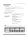
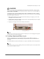
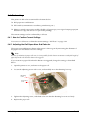
1.4.6.3 Example Scanning Result
1
3
1
56
1
The whole of the card (one side) can be scanned. The data size is 56 × 90 mm including a 1 ~
3mm {0.040 ~ 0.0118"} border beyond the edges of the card.
90
Card insertion direction
[Units: mm]
All numerical Values are typical.
Rev. E
General Information 1-21
1.4.6.4 Notes on Using the Card Image Scanner
❏ Notes on card
•
The side to be scanned must be up when it is inserted.
•
Make sure to use a flat card without excessive curvature, cracking, or embossing.
Otherwise, the card feeding may be affected.
•
When you use an IC card, be sure not to touch the contacts on it.
•
Since the card sensor uses a transmissive photo sensor, do not use a card with a hole or a
transmissive area in the sensor position.
7
2
Prohibited area for a hole or
a transmissive area.
Card insertion direction
[Units: mm]
All numerical Values are typical.
❏ Quality of image data
An appropriate quality of the scanning result may not be obtained in the following cases:
•
A card that has excessive curvature, cracking, or damage.
•
A card that has embossing.
•
When excessively bright external light affects the image scanning.
•
When the glass of the image scanner is scratched by a foreign substance such as sand.
1-22 General Information
Rev. E
TM-H6000III Technical Reference Guide
1.5 Sensors
1.5.1 Paper Sensors
1.5.1.1 Receipt section
❏ Paper roll near-end sensor:
•
The sensor is located on the roll paper supply device on the receipt section. It detects the
near-end of the paper roll by detecting the paper roll diameter. You can adjust the
sensor. See Chapter 5 for details on adjustment.
•
When the printer detects a paper near-end, it either stops or continues printing,
depending on the Paper sensor command setting.
•
When the sensor is selected to stop printing and the sensor detects a paper near-end, the
printer automatically goes offline after printing the current line. To restart printing, load
the paper and set the printer back online by closing the printer cover. The printer starts
initializing and continues printing data stored in the print buffer.
❏ Paper roll end sensor:
•
The paper roll end sensor is located in the paper path on the receipt section. It detects the
presence of paper in the paper path of the printer mechanism.
•
When there is no paper in the paper path, the PAPER OUT LED lights.
•
When the sensor detects a paper end, printing stops even if it is in the middle of one
transaction; therefore, it is recommended to use the paper roll near-end sensor and use
the paper end sensor as a supplement.
1.5.1.2 Slip/ Validation section
❏ TOF (Top of Form) sensor:
•
The slip TOF sensor is located in the slip paper path and detects the presence of slip
paper in the paper path. The SLIP LED lights accordingly.
❏ BOF (Bottom of Form) sensor:
Rev. E
•
The sensor is located in the slip entrance and detects whether the paper is inserted
correctly and whether it is removed or not. The printer does not proceed to the next
operation until the paper has been inserted correctly or removed. (The SLIP LED
continues blinking.)
•
When the printer detects a paper end, it either stops or continues printing depending on
the Paper sensor command setting.
•
When the sensor is selected to stop printing, the sensor detects a paper-end and the
printer prints data up to the end of the printable area, ejects the slip when all the next
print data is transmitted, and then waits for the slip to be removed. After the slip is
removed, the printer enters the paper insertion waiting state.
General Information 1-23
❏ Validation sensor:
The validation sensor is located below the validation paper path and detects whether the
paper is inserted correctly or not. The printer does not proceed to the next operation until
the paper has been removed. (The SLIP LED continues flashing.)
❏ Slip/Validation eject sensor:
The slip/validation eject sensor is located in the slip paper exit and detects whether the
paper is removed or not after printing. The printer does not proceed to the next operation
until the paper has been removed.
1.5.2 Printer Cover Sensors
1.5.2.1 Receipt section
❏ Paper roll cover open sensor:
•
When a paper roll is selected as the print sheet, if the sensor detects a cover open during
printing, the printer goes offline, stops printing immediately, and the ERROR LED
blinks. Even if the cover is closed, the ERROR LED still blinks. You need to transmit the
error recovery command to recover.
If the printer continues printing, it starts printing from the beginning of the line where
the error occurred; therefore, double printing or printing position shift may occur. It is
recommended to clear the buffers and resend the print data.
•
When a slip is selected as the print sheet, if the sensor detects a cover open during
printing, the printer finishes printing data for the line when the cover open is detected,
then stops the carriage movement and goes offline. The printer goes online when the
cover is closed and restarts printing.
❏ Unit cover open sensor:
•
When the sensor detects a unit cover open during printing, the printer goes offline
depending on the setting of bit 8 for the memory switch.
The default is that the printer finishes printing data for the line when the cover open is
detected and stops printing. The printer goes online when the cover is closed and
restarts printing.
If a recoverable error is selected by memory switch, the printer goes offline, stops
printing immediately and the ERROR LED blinks. Even if the cover is closed, the
ERROR LED still blinks. You need to transmit the error recovery command to recover. If
the printer continues printing, it starts printing from the beginning of the line where the
error occurred. In this case, double printing or printing position shift may occur. It is
recommended to clear the buffers and resend the print data.
1.5.2.2 Slip section
❏ Front cover open sensor:
When the sensor detects a cover open during printing, the printer finishes printing data for
the line when the cover open is detected, then stops the carriage movement and goes offline.
The printer goes online when the cover is closed and restarts printing.
1-24 General Information
Rev. E
TM-H6000III Technical Reference Guide
1.6 Other Specifications
1.6.1 Internal Buffer
1. Receive buffer selectable as 45 Byte or 4 KB using the DIP switch.
2. User-defined buffer (both for user-defined characters and user-defined bit images)
Receipt: 12KB; Slip: Approximately 3KB
3. Macro buffer 2KB
4. NV (non-volatile) bit image buffer 384KB
5. NV (non-volatile) user memory 1KB
1.6.2 Electrical Characteristics
Supply voltage:
+24 V ± 10% (optional power supply: EPSON PS-180)
Ripple voltage: 300 mVpp or less
(only when the printer is used with the MICR reader)
Current consumption (at
24V except for drawer
kickout driving):
Slip: Operating:
Mean: Approximately 1.7A
(Character font A α-N, all columns printing)
Peak: Approximately 5.5A
Receipt: Operating:
Mean: Approximately 1.8A
(Character font A α-N, all columns printing)
Peak: Approximately 7.7A
Card Image Scanner:
Operating: Mean:Approximately 0.5A
Peak: Approximately 0.6A
Standby:
Mean: Approximately 0.2A
Note:
The current consumption is as follows when a receipt is printed in low temperature. Take in consideration
if a power supply other than the Epson specified one is used or the print pattern is different.
Print pattern
See figure ’A’ below
See figure ’B’ below
See figure ’C’ below
Print duty
18% (Alphanumeric
in full column)
50%
100%
Current value (A) at
Peak
Mean
Peak
Mean
Peak
Mean
5C°
7.7
1.8
8.5
3.5
9.5
5.0
Rev. E
General Information 1-25
❏ The values in the table above are measured in the following conditions, but are just for your
reference.
❏ The Epson original power supply PS-180 can print within the print duty above.
❏ Contact Epson if you need more detailed information.
Environmental temperature:
Supply voltage:
Print pattern:
Measurement terminal:
Print density:
Ԙ
Figure
’A’
5° C {41° F}
24 V
See figures below
At the connector of the printer's power supply
Print density level 2
The print density levels 3 and 4 are higher by +15% and +30%
respectively than the value of the level 2 in the table above.
Figure
ԙ ’B’
Figure
’C’
Ԛ
abcd
300 mm
300 mm
7890
42 columns
(Font A)
72 mm
72 mm
Alphanumeric rolling pattern with
full column printing
1 dot for square
1-26 General Information
Rev. E
TM-H6000III Technical Reference Guide
Note:
Notes on using the Epson PS-180 power supply unit
If the printing is continuously performed with the high print ratio, the overcurrent limitation
might be operated.
Therefore, the printing length must not exceed the following values when printing withhigh print ration.
Print ratio: Number of dots being energized per one dotline / Total number of dots per one dotline
(512 dots)
Limitation of the Printing Length on Print Ratio
Print ratio
Print
example
80%
50%
72mm
Print length
--
100%
58mm
30 mm or less
72mm
20 mm or less
If the overcurrent limitation is operated when printing is continuously performed with a high print ratio,
uneven print density or a low voltage error may occur.
Rev. E
General Information 1-27
1.6.3 Reliability
1.6.3.1 Receipt printer section:
Life:
Mechanism: 15,000,000 lines (when using monochrome
thermal paper), 7,500,000 lines (when using two-color
thermal paper)
The printer is defined to have reached the end of its life when
it reaches the beginning of the Wearout Period.
MTBF:
360,000 hours
In the printer’s life of 15 million lines (in monochrome
printing) or 7.5 million lines (in two-color printing). Failure is
defined as a Random Failure occurring at the time of the
Random Failure Period.
MCBF:
72,000,000 lines
This is an average failure interval based on failures relating to
Wearout and Random Failures up to the life of 15 million
lines (in monochrome printing) or 7.5 million lines (in twocolor printing).
Thermal head life:
100 million pulses, 100 km (when using monochrome thermal
paper), 50 km (when using two-color thermal paper)
Autocutter life:
1,500,000 cuts
1.6.3.2 Slip/Validation printer section:
Life:
Mechanism: 15,000,000 lines
The printer is each defined to have reached the end of its life
when it reaches the beginning of the Wearout Period.
MTBF:
180,000 hours
Failure is defined as a Random Failure occurring during the
Random Failure Period.
MCBF:
37,000,000 lines
This is an average failure interval based on failures relating to
Wearout and Random Failures up to the life of 15 million
lines.
1-28 General Information
Rev. E
TM-H6000III Technical Reference Guide
Print head life:
200 million characters (when printed with Font B only)
Note
Printing pattern: Average 2 dots / wire per character
This printer has nine wire (dots) vertically and prints characters
moving horizontally. If one wire prints repeatedly, the problem may
occur. Consider this when you use the printer.
Example:
If the characters which consists of the horizontally adjacent dots
such as "H", "L", "-", or " A" are repeatedly printed, the number of
the printed lines should be ten or less. If more than ten such lines
need to be printed, the printer should pause for a time longer the
total printing time for each 10 lines.
1.6.3.3 Endorsement print mechanism section:
Life:
Mechanism: 1,350,000 lines
The printer is defined to have reached the end of its life when
it reaches the beginning of the Wearout Period.
MTBF:
180,000 hours
Failure is defined as a Random Failure occurring at the time
of the Random Failure Period.
MCBF:
3,300,000 lines
This is an average failure interval based on failures relating to
Wearout and Random Failures up to the life of 1.35 million
lines.
1.6.3.4 MICR section:
MICR reader mechanism:
240,000 passes (when used with US personal checks)
1.6.3.5 Image scanner section:
Image scanner mechanism:
240,000 passes (when used with US personal checks)
1.6.3.6 Card Image scanner section
Image scanner mechanism:
Rev. E
240,000 passes
General Information 1-29
1.6.4 Environmental Conditions
Temperature:
Operating: 5 C° to 45 C° {41F° to 113F° }
Storage: –10C° to 50 C° {14F° to 122F° }
(except for paper and ribbon)
Humidity:
Operating: 10 to 90% RH
Storage: 10 to 90% RH (except for paper and ribbon)
90
80
60
Relative humidity
Operating environment
range
40
20
10
0
0
10
20
30
40
50
Ambient
temperature
Operating temperature and humidity range
Vibration resistance:
When packed:
Frequency: 5 to 55 Hz
Acceleration: 2 G
Sweep: 10 minutes (half cycle)
Duration: 1 hour
Directions: x, y, and z
No external or internal damage should be found after the
vibration test, and the unit should operate normally.
Impact resistance:
When packed:
Package: EPSON standard package
Height: 50 cm {19.69"}
Directions: 1 corner, 3 edges, and 6 surfaces
No external or internal damage should be found after the
drop test, and the unit should operate normally.
When unpacked:
Height: 5 cm {1.97"}
Directions: Lift one edge and release it (for all 4 edges).
When the printer is not printing, no external or internal
damage should be found after the drop test.
Acoustic noise (operating):
1-30 General Information
Receipt:
When using autocutter:
Approximately 52 dB (bystander position)
Rev. E
TM-H6000III Technical Reference Guide
1.6.5 Installation
The printer must be installed horizontally.
1.6.6 Interfaces
❏ USB
❏ RS-232
❏ IEEE 1284 bidirectional parallel
❏ 10BASE-T/100BASE-TX
❏ RS-485
1.7 Notes for Barcode printing on slip printer
This printer supports the barcode printing on roll paper and slips. Note the following when a
barcode is printed on the slip/validation.
❏ Ladder barcode is not supported.
❏ HRI character must be added.
❏ Use the ERC-32(B) black ink ribbon cassette.
❏ Recognized rate of barcode reading may differ with density, gradation, or performance
capabilities of a barcode reader to be used. Therefore, process the barcode with HRI
characters which can be used if the barcode is unable to be read.
Rev. E
General Information 1-31
1.8 External Dimensions and Weight
Width:
186 mm {7.32"}
Depth:
298 mm {11.73"}(except for the protrusion)
Height: 185 mm {7.28"}
185 mm {7.28"} Image Scanner model
209 mm {8.23"} Photo-ID model
Weight: Approximately 5.3 kg {11.7 lb}
Approximately 5.7 kg {12.6 lb} Image Scanner model
Approximately 5.9 kg {13.0 lb} Photo-ID model
(All the numeric values are typical.)
Color:
White (ECW), Dark Gray(EDG)
298
TM-H6000III:
185
186
1-32 General Information
Rev. E
TM-H6000III Technical Reference Guide
298
With Image scanner model:
185
186
Rev. E
General Information 1-33
298
Photo-ID model:
209
186
1-34 General Information
Rev. E
TM-H6000III Technical Reference Guide
1.9 Maintenance Area
282
203
56
298
(Photo ID model:88)
NOTE:
203 mm =
56 mm =
298 mm =
47 mm =
282 mm =
Rev. E
8.0"
2.1"
11.7"
1.9"
11.1"
(Photo ID model:280)
(Photo ID model:203)
The illustrations below show the area around the printer required for maintenance.
47
(Photo ID model:69)
(Photo-ID model)
203 mm = 8.0"
88 mm = 3.5"
298 mm = 11.7"
69 mm = 2.7"
280 mm = 11.0"
General Information 1-35
1-36 General Information
Rev. E
TM-H6000III Technical Reference Guide
Chapter 2
System Planning
This section provides you information for system planning.
2.1 Control Method
A TM printer can print and be controlled using any of the following three methods:
1. Windows printer driver (EPSON Advanced Printer Driver)
2. UPOS (OPOS, OPOS for .NET, JavaPOS)
3. ESC/POS commands
Depending on the driver or interface to be used, an IP setting tool for the Ethernet specification
and a logo registration utility for printing (TMFlash logo utility) are provided.
See “Downloading Drivers, Utilities, and Manuals” on page 2-4.
2.1.1 Windows Driver (EPSON Advanced Printer Driver)
The EPSON Advanced Printer Driver is a method for controlling the TM printer in the same
manner as the Windows standard printer driver.
2.1.1.1 General Features of EPSON Advanced Printer Driver
❏ Easy
•
Allows you to print from commercially available applications, since the APD is a
Windows driver.
•
Allows you to print a Barcode and 2D-Code with the fonts built in the APD.
•
Allow you to print logos and graphics.
•
Allows you to send the paper cut command to the TM printer.
•
Allows you to send the open command to the cash drawer.
❏ Fast
Rev. E
•
Achieves high speed printing using the Device fonts of the TM printer.
•
Allows you to convert the Windows fonts to the Device fonts.
•
Allows you to print an image such as a store logo faster by registering the image in the
TM printer.
System Planning 2-1
❏ Convenience
•
Allows you to make horizontally long printings by rotated printing, for example
landscape format receipt. When using the TM printer oriented vertically (wall mount), it
can print backward to make it easy to read for customers.
•
Allows you to print images as a background.
❏ Expandability
•
Printer sharing is supported. Allows you to share TM printer with other computers on a
network. (Printer sharing through a print server is not supported.)
•
Allows you to use ESC/POS commands control.
❏ Programming
•
Win32/.Net environment is supported. See the “Status API Manual” to find out which
development language is supported.
•
Allows you to check the status of the device (TM printer) by using the Status API.
❏ Installation
•
Allows you to copy the existing settings of the APD environment to other computers.
(Silent Install)
•
After the APD installation, the printer driver will be automatically installed to the TM
printer equipped with a USB interface by the Plug and Play function.
❏ Compatibility
•
Note that APD 4.xx cannot coexist with APD 2.xx or 3.xx.
Note:
When you install APD 4.xx in an environment in which APD 2.xx or 3.xx is already
installed, APD first automatically uninstalls the previous version before installing 4.xx
•
Coexistence with OPOS in a computer is not possible.
2-2 System Planning
Rev. E
TM-H6000III Technical Reference Guide
2.1.1.2 EPSON Advanced Printer Driver Supported Environment
❏ Supported interfaces
•
Parallel
•
Serial
•
USB
USB 2.0 compliant (Full-Speed 12 Mbps operation. High-Speed operation is not
possible.)
•
Ethernet (10/100 Base-T)
•
Wireless LAN (IEEE 802.11b)
❏ Supported Operating Systems
•
Microsoft Windows Vista SP1 (32bit) English version
•
Microsoft Windows XP Professional SP3 (32bit) English version
•
Microsoft Windows XP Embedded SP2 English version
Note:
It cannot be used in the Terminal Server environment.
❏ Supported Development Languages
Win32:
•
Visual Basic 6.0
•
Visual C++
.NET:
•
Visual Basic .NET
•
Visual C#
Note:
If you use Status API .NET Wrapper in Windows XP, install .NET Frame Work 2.0 or later before
installing APD.
2.1.1.3 Sample Program
Sample programs using the APD are provided in supported development languages.
Rev. E
System Planning 2-3
2.1.2 UPOS
UPOS is a driver formulated for POS application development complying with the UPOS
specification.
2.1.2.1 UPOS Driver
❏ OPOS
A driver using the OLE technology. Visual Basic/Visual C++ are used as the development
language.
❏ OPOS for .NET
A driver using the Microsoft .NET Framework technology. Complies with POS for .NET.
Visual Basic .NET/Visual C# are used as the development language.
❏ JavaPOS
A driver using the Java technology. Supports Windows/Linux as the operation
environment. Java SE Development Kit is used as the development language.
2.1.2.2 Downloading UPOS Driver
Go to the web site below to download the UPOS driver.
http://www.epsonexpert.com/
2.1.3 ESC/POS Command
Print/control by ESC/POS commands is direct control for TM printers using the ESC/POS
commands proposed by EPSON. Sending ESC/POS commands to the printer from an
application enables direct control of the printer. For the detailed information regarding the
ESC/POS commands, please contact EPSON or your dealer.
2.1.4 Downloading Drivers, Utilities, and Manuals
Drivers, utilities, and manuals can be downloaded from one of the following URLs:
For customers from North America, go to the following web site:
http://www.epsonexpert.com/
For customers in other countries, go to the following web site:
http://www.epson-pos.com/
2-4 System Planning
Rev. E
TM-H6000III Technical Reference Guide
2.2 Connection Form and Cables
2.2.1 USB
The TM printer can be connected to the host PC via a USB connector, and other TM printers can
be connected to the first printer via USB. (See “Changing the DIP Switch Settings” in Chapter 3
for DIP switch settings.)
Modular
Self-powered USB HUB
Cash drawer
(Photo-ID model Only)
Note:
The host PC needs to have an installed “USB device driver” for using USB model TM printer. See
“Downloading Drivers, Utilities, and Manuals” on page 2-4. See the readme_e.txt of the driver for the
procedure for installing.
EPSON does not supply the port driver or similar program necessary to control the USB interface printer
with the ESC/POS commands. Control it with the driver (APD, OPOS or JavaPOS).
If you connect a Customer Display, set DIP switch settings as follows. For details, see the User’s Manual
packed with your Customer Display.
Item
Transmission setting
Selection
Transmission speed
19200 bps
Parity
None
Data word length
8 bits
Before turning on the printer, be sure to turn on the Customer Display. If you reverse the order, the
Customer Display will not be recognized correctly.
To satisfy the EMI standard, be sure to mount the ferrite core on the display module cable. To mount the
ferrite core, put the display module cable into the ferrite core.
See also “FAQ” on page C-1 for more details.
Rev. E
System Planning 2-5
2.3 Serial Connection
When the TM printer is connected to the host PC with a serial interface, the following connection
forms are possible:
•
Stand alone
•
Y-connection
•
Pass-through connection
Connections for usable serial cross cables are as follows:
The type of cable that should be used depends on the operation and the handshake method for
the TM printer. You can operate the TM printer by Windows driver, OPOS, JavaPOS, or ESC/
POS commands. XON/XOFF, DTR/DSR, or RTS/CTS are available as handshake controls. See
tables in following sections for the type of cable for each connection.
2-6 System Planning
Rev. E
TM-H6000III Technical Reference Guide
2.3.1 Stand alone
Both TM printer and Customer Display are connected to the host PC via serial port.
2
1
Application XON/XOFF
TM side
control
control setting
(except OPOS)
DTR/DSR
(DOS, OPOS, Visual C)
RTS/CTS
(DOS, Windows driver, Visual C,
Visual Basic, MSComm)
XON/XOFF
1
Type A or B
—
—
2
DM-D500: A,B
Other DM-D: not available
—
—
1
—
Type A or B
Type B
2
—
Type A or B
Type B
DTR/DSR
2.3.2 Y-connection
TM printer is connected to the host PC via serial port and the Customer Display is connected to
TM printer via modular connector.
Application XON/XOFF
TM side
control (except OPOS)
control setting
DTR/DSR
(DOS, OPOS, Visual C)
RTS/CTS
(DOS, Windows driver, Visual C,
Visual Basic, MSComm)
XON/XOFF
Not available
—
—
DTR/DSR
—
Type B (*)
Type B
(*) When RTS/CTS control is used between the TM and Customer Display.
Note:
You need to use the UB-S09 interface when you use a modular connector.
On a Customer Display (DM-D500 etc...) device that has a DIP switch to select the Y-type connection,
confirm that the DIP switch has been set to “Y-type connection: Enable.” For details of the DIP switch,
see the User’s Manual packed with your Customer Display.
Rev. E
System Planning 2-7
2.3.3 Pass-Through Connections
The TM printer is connected to the Customer Display via a serial port, and the Customer Display
is connected to the host PC via a serial port.
Note:
On a Customer Display (DM-D500 etc...) device that has a DIP switch to select the Y-type connection,
confirm that the DIP switch has been set to “Y-type connection: Disable.” For details of the DIP switch,
see the User’s Manual packed with your Customer Display.
Application XON/XOFF
TM side
control
control setting
(except OPOS)
DTR/DSR
(DOS, OPOS, Visual C)
RTS/CTS
(DOS, Windows driver, Visual C,
Visual Basic, MSComm)
XON/XOFF
Not available
—
—
1
—
Type A or B
Type B
2
—
Type A or B
Type A or B
DTR/DSR
2.4 Parallel Connection
The TM printer is connected to the host PC via a parallel interface board (UB-P02II). The
Customer Display is connected to the host PC via a serial port.
2-8 System Planning
Rev. E
TM-H6000III Technical Reference Guide
2.5 Ethernet
TM printers are connected to a network via a hub using an Ethernet cable.
Note:
If the TM printer is connected to the host PC via an Ethernet interface, a Customer Display cannot be
connected to the TM printer.
We provide the IP address setup utility“EPSON TMNet WinConfig,” for setting the IP address of the
Ethernet model TM printer on the host PC. It is downloadable from the web site. See “Downloading
Drivers, Utilities, and Manuals” on page 2-4.
The Ethernet interface TM printer does not accept a Customer Display. Connect the Customer Display to
a POS terminal or appropriate equipment other than the printer.
When controlling the printer with OPOS, it is necessary to use exclusive control. Therefore, when using 1
printer with several PCs, it is necessary to consider that application programming by a PC that already
has the exclusive right must release it; then another PC must claim it.
Names of parts
The names of the various parts of the Ethernet interface are shown below.
10BASE-T/100BASE-TX Ethernet
interface connector
LED (Green)
Rev. E
LED (Yellow)
Push button
To print the parameters for the interface,
press the button and hold it for more than 3 seconds.
System Planning 2-9
Connection procedure
CAUTION:
Connecting devices directly to LAN cables that are installed outdoors will expose them
to damage from power surges caused by lightning and other inductive sources. It is best
to make sure that devices without proper surge protection are cushioned by being
connected through devices that do have surge protection. Otherwise, it is better not to
connect them to outdoor lines.
Never attempt to connect the Customer Display cable, drawer kick out cable or the
standard telephone line cable to the 10 Base-T Ethernet connector.
1. Confirm that the power supplies for both the printer and the host computer have been
turned off.
2. Connect the 10 Base-T cable to the 10 Base-T Ethernet connector by pressing firmly until the
connectors click.
Note:
For the various methods of setting the Ethernet interface, refer to the Technical Reference Guide for the
interface. It is downloadable from the web site. See “Downloading Drivers, Utilities, and Manuals” on
page 2-4.
2-10 System Planning
Rev. E
TM-H6000III Technical Reference Guide
Chapter 3
Setup
3.1 Part Name and Basic Operation
3.1.1 Part Names
TM-H6000III
Validation entrance
(validation model only)
roll paper cover
unit cover
front cover
control panel
power switch
Slip entrance
TM-H6000III with Image Scanner model
roll paper cover
control panel
unit cover
front cover
power switch
Rev. E
Setup 3-1
TM-H6000III Photo-ID model
LEDs for card scanner
card entrance for scan
roll paper cover
unit cover
control panel
front cover
power switch
3.1.2 Connectors
WARNING:
Do not connect a telephone line to the drawer kick-out connector or the display module connector;
otherwise the printer and the telephone line may be damaged.
You can connect up to four cables to the printer. They all connect to the connector panel (on the
bottom rear of the printer), which is shown below.
interface
connector
display module
connector
drawer kick-out
connector
power supply
connector
Note:
This illustration shows the serial interface model. The parallel interface connector and USB looks slightly
different.
3-2 Setup
Rev. E
TM-H6000III Technical Reference Guide
3.1.2.1 Important Installation Notes
❏ For a serial interface, use a null modem cable.
❏ For a parallel interface, use an IEEE 1284 cable.
❏ For a USB interface, install the driver before connecting the printer.
3.1.3 The Control Panel
Control Panel
ERROR LED
SLIP LED
Photo-ID Model
Card Panel
RELEASE BUTTON
ID LED
FEED BUTTON
PAPER OUT LED
POWER LED
ERROR LED
(Card scanner section)
3.1.3.1 LED
POWER
This light is on when the power is turned on.
ERROR
When this light is on but not blinking, it means that the printer is offline. Check to see if a cover
is open. When this light is blinking, there is an error. See “LED Blinking Pattern” in Chapter 4
PAPER OUT
This light comes on when the printer is out, or nearly out, of roll paper. The printer has a paper
end detector, and it also has a near-end detector (which can be adjusted) to warn you that the
printer is nearly out of paper. See “Adjusting the Roll Paper Near End Detector” (page 3-18) for
information on adjusting the detector.
This light blinks during the self-test printing standby state or macro execution standby state
(when the macro execution command is used).
Rev. E
Setup 3-3
SLIP
❏ This light blinks when the printer is ready to receive slip paper. It stays on during printing
on slip paper and blinks again when slip paper should be removed. When the slip paper is
removed in the slip removal waiting state, the printer enters the paper roll mode two
seconds later. The SLIP LED light is on during this time. The blinking patterns for the slip
inserting and removal waiting states are different as follows:
SLIP LED Blinking Pattern
State
320 ms
Slip insertion waiting
Slip removal waiting
Check insertion waiting
(only for MICR-equipped model)
2080 ms
1760 ms
3.1.3.2 LEDs on the Card panel
ID
On: Card scanner is operating.
Off: Card scanner is not selected.
Flashing: Card insertion / removal waiting state (refer to the following table).
SLIP LED Blinking Pattern
State
160 ms
Card insertion waiting
Card removal waiting
3-4 Setup
2080 ms
Rev. E
TM-H6000III Technical Reference Guide
ERROR
Off: Normal condition.
Flashing: Error (refer to the following figure).
SLIP LED Blinking Pattern
320 ms
State
Card Ejection error
5120 ms
3.1.3.3 Control Panel Buttons
The control panel has two paper buttons that you may have to use, although most paper
handling functions will be handled by your software.
FEED
Use this button to feed roll paper or to start a roll paper self test. (See the instructions later in this
chapter.)
RELEASE
Use this button to release slip paper or to start a slip paper self test. (See the instructions later in
this chapter.)
Panel Button Operations
ESC/POS command can be set to enable or disable the panel buttons.
3.1.4 Validation paper handling (Option)
1. Transmit the command from host PC to make the printer ready for a validation paper to
be inserted.
2. Insert a validation paper into the validation entrance from the upper side.
insert the paper against the corner
incorrect insertion
correct insertion
Note:
Use only validation paper (flat paper, without wrinkles, creases, or folds) that matches the
specifications.The validation function is a factory option.
Rev. E
Setup 3-5
3.1.5 Card insertion method (Option)
When you would like to scan a card with the TM-H6000III with Photo-ID, follow the following
procedure.
1. Transmit control command to TM-H6000III from your application for card insertion.
Note:
The control command depends on your control method. See Chapter 5 or Chapter 6 according to your
method for confirming the command.
2. When the TM-H6000III receives the transmitted control
command, the ID LED blinks. Insert the card face up into the
card entrance as far as far it will go.
(See illustration on the right.)
3. The printer will detect the card and start drawing it in. When the printer starts drawing it in,
let go of the card immediately.
4. The printer scans the card while ejecting it.
5. When the ID light starts flashing again, remove the card by pulling it straight out; do not
pull it at an angle.
Note:
Appropriate image data quality might not be acquired in the following conditions:
•
•
•
•
3-6 Setup
Excessive damage such as curvature, cracking, or folding of the card.
Embossed cards.
When the image scanner part is exposed to excessive light such as sunlight, a spotlight, or
fluorescent lamp.
When the scanner glass has been damaged by foreign matter such as sand.
Rev. E
TM-H6000III Technical Reference Guide
3.2 Setup Flow
You have to set up your printer to use it. And you can adjust some feature by customizing them.
This section describes the setup.
The set up flow of preparing to use printer is below..
Printer setup (See “Printer setup,” page 3-8)
Printer customizing
(See “Customizing,” page 3-18)
Driver setup
❏ APD
❏ OPOS
❏ OPOS for .NET
❏ JavaPOS
Complete set up
Note:
When you use OPOS (OCX driver from EPSON), Advanced Printer Driver, or JavaPOS, you need to
install the driver. When you use ESC/POS commands, you don’t have to install drivers. For information
on these drivers, see “Control Method” (page 2-1).
Rev. E
Setup 3-7
3.3 Printer setup
This section describes the setup. The flow of preparing to use printer is below
Start set up
1. Connect power supply (PS-180)
2. Install ribbon cassette(s)
2. Installing the Endorsement Ribbon Cassette
(Endorsement function is a factory option)
3. Install roll paper
4. Connect the printer to host PC / POS terminal
Complete set up
Note:
If your printer is equipped with the endorsement function, you also need to install the endorsement ribbon
cassette, which is smaller than the standard ribbon cassette. If your printer isn’t equipped with the
endorsement function, you don’t need to install it.
When you use this printer with a serial interface, you have to adjust the communication settings.
See “Customizing” (page 3-18) for how to set them.
3.3.1 Connecting the Power Supply Unit (PS-180)
Use the optional EPSON PS-180 power supply or equivalent for your printer.
WARNING:
Make sure you use the EPSON PS-180 power supply or equivalent. Using an incorrect
power supply may cause fire or electrical shock.
3-8 Setup
Rev. E
TM-H6000III Technical Reference Guide
CAUTION:
When connecting or disconnecting the power supply from the printer, make sure the
power supply is not plugged into an electrical outlet. Otherwise you may damage the
power supply or the printer.
If the power supply’s rated voltage and your outlet’s voltage do not match, contact
your dealer for assistance. Do not plug in the power cord. Otherwise you may damage
the power supply or the printer.
1. Make sure the printer’s power switch is turned off, and the power supply’s power cord is
unplugged from the electrical outlet.
2. Check the label on the power supply to make sure the voltage required by the power supply
matches that of your electrical outlet.
3. Plug the power supply cord into the connector shown below.
Power supply connector
Note:
To remove the DC cable connector, make sure the power supply’s power cord is unplugged; then grasp the
connector at the arrow and pull it straight out.
3.3.2 Installing or Replacing the Ribbon Cassette
EPSON recommends the use of genuine EPSON ribbon cassettes. Ribbon cassettes not
manufactured by EPSON may cause damage to your printer that is not covered by EPSON’s
warranties.
To install the ribbon cassette for the first time or to replace a used ribbon, follow the steps below:
Note:
Be sure to turn on the power before installing a ribbon cassette. When the printer is turned off, the ribbon
cassette cannot be installed or removed.
Rev. E
Setup 3-9
1. Unpack the ribbon cassette and turn the knob in the direction shown to take up any slack.
Knob
2. Open the front cover of the printer, using the tabs on each side of the cover.
Tab
3. Remove the old ribbon, if there is one.
4. Insert the new ribbon cassette as shown.
3-10 Setup
Rev. E
TM-H6000III Technical Reference Guide
5. Turn the knob two or three times to make sure the ribbon is seated correctly. You can also
look at the side of the slip unit to see if the ribbon is in the correct place. See below.
Edge of
ribbon cassette
6. Close the front cover of the printer.
Rev. E
Setup 3-11
3.3.3 Installing or Replacing the Endorsement Ribbon Cassette
If your printer is equipped with the endorsement function, you also need to install the
endorsement ribbon cassette, which is smaller than the standard ribbon cassette.
EPSON recommends the use of genuine EPSON ribbon cassettes. Ribbon cassettes not
manufactured by EPSON may cause damage to your printer that is not covered by EPSON’s
warranties.
Note:
Be sure to turn on the power before installing a ribbon cassette.
1. Unpack the ribbon cassette and turn the knob in the direction shown to take up any slack.
2. Open the unit cover, as shown below. Inside the printer, push the levers backward to open
the unit.
Note:
Do not open the unit during printing.
3-12 Setup
Rev. E
TM-H6000III Technical Reference Guide
3. Insert the ribbon cartridge into the printer. You can see a properly installed ribbon in the
illustration below.
4. Turn the knob two or three times to make sure that the ribbon is seated correctly.
5. Close the cover of the printer.
3.3.4 Installing or Replacing the Paper Roll
Note:
Do not use paper rolls that have the paper glued or taped to the core because they might cause a paper jam.
To prevent paper jams, make sure that nothing obstructs paper coming out of the paper exit, and do not
pull the paper out of the printer.
1. To prevent data loss make sure that the printer is not receiving data.
2. Open the paper roll cover by lifting up the two tabs on the paper roll cover and then pushing
the cover back.
3. Remove the used paper roll core if there is one.
4. Insert the paper roll as shown.
Rev. E
Setup 3-13
5. Be sure to note the correct direction that the paper should come off the roll.
6. Pull out a small amount of paper, as shown. Then close the cover and tear off the extra paper
by pulling it toward the front of the printer.
3-14 Setup
Rev. E
TM-H6000III Technical Reference Guide
3.3.5 Connecting the Printer to the Host PC / POS Terminal
All cables are connected to the connector panel located on the lower rear side of the printer.
Drawer kick connector
Interface connector
Customer Display
(DM-D) connector
Power supply connector
Connector panel
Note:
The figure above shows the connector panel for the RS-232/RS-485 interface model printer. The shape of
the interface connector varies according to the type of interface used.
Be sure to turn off the power supply for both the printer and the host computer unit before connecting the
various cables.
3.3.5.1 Serial interface model
Before connecting any of the cables, make sure that both the printer and the host PC are turned
off.
You need an appropriate serial, parallel, USB, or Ethernet interface cable to connect your
computer to the printer. For the serial model, it is important that you use a null modem cable,
not any other serial cable, and for the parallel model use an IEEE 1284 cable.
1. Plug the cable connector securely into the printer’s interface connector.
2. If the cable connector has screws on it, tighten the screws on both sides of the connector.
3. If your interface connector has a grounding wire, attach it to the printer using the screw
labeled FG, which is next to the interface connector.
4. Attach the other end of the cable to the host PC.
Note:
When using serial interface, you need to adjust serial communication using the DIP switches. See
“Adjusting the DIP Switches” (page 3-19) for details.
Rev. E
Setup 3-15
3.3.5.2 Parallel Interface Models
1. Press the connector on the end of the interface cable firmly into the interface connector on
the connector panel.
2. Press down the clips on either side of the connector to lock it in place.
3. For interface cables equipped with a ground line, attach the ground line to the screw hole
marked "FG" on the printer.
4. Connect the other end of the interface cable to the host computer.
3.3.5.3 USB Interface Models
1. Attach the locking wire saddle at the location shown in the figure below.
2. Hook the USB cable through the locking wire saddle, as shown in the figure below.
Note:
Hooking the USB cable through the locking wire saddle, as shown in the figure below, will prevent the
cable from coming unplugged.
Locking wire saddle
Attaching locking wire saddle
3. Connect the USB cable from the host computer to the USB upstream connector.
3-16 Setup
Rev. E
TM-H6000III Technical Reference Guide
3.3.5.4 Connecting a Drawer
CAUTION:
Be sure to connect a drawer that meets printer specifications. Connecting a drawer of
the wrong specifications may result in damage to both the drawer and the printer.
Never connect a telephone line to the drawer kick out connector (labeled “DK”).
Doing so may result in damage to both the telephone line and the printer.
Never connect the drawer cable to the customer display connector (labeled “DM-D”).
Doing so may result in damage to both the drawer cable and the printer.
1. Connect the drawer cable to the drawer kick out connector (labeled “DK”) on the connector
panel.
Drawer kick connector
Interface connector
Customer Display
(DM-D) connector
Power supply connector
Connecting drawer
2. The connecting is finished.
Rev. E
Setup 3-17
3.4 Customizing
This printer is able to be customized for the items below:
❏ Roll paper near end detector
❏ DIP switch (communication condition, print density, etc...)
❏ Memory switch (some notices enable/disable, roll paper type, error signal output, paper jam
detection for slip, and unit cover open while printing)
The current settings can be confirmed by a self-test.
3.4.1 How to Confirm Current Settings
You can use a self-test to confirm the current settings. “Self Tests” on page 3-24
3.4.2 Adjusting the Roll Paper Near End Detector
The paper near end detector detects when paper is almost gone by measuring the diameter of
the paper roll. The detector has two settings.
Note:
Because of variations in paper roll cores, it is not possible for the detector to measure exactly the length of
paper left on the roll when the detector is triggered.
If you want more paper left when the detector is triggered, change the setting, as described
below.
1. Open the printer cover, and remove the paper roll.
2. Loosen the adjusting screw with a coin, and carefully move the detecting lever up.
Adjusting
screw
Detecting
lever
3. Tighten the adjusting screw, and check to be sure that the detecting lever moves freely.
4. Replace the paper roll.
3-18 Setup
Rev. E
TM-H6000III Technical Reference Guide
3.4.3 Adjusting the DIP Switches
The printer has two sets of DIP switches. The function of the DIP switches is different for each
interface model.
3.4.3.1 Changing the DIP Switch Settings
If you need to change settings, follow the steps below to make your changes:
CAUTION:
Turn off the power while removing the DIP switch cover to prevent an electric short,
which can damage the printer.
Use a crosshead screwdriver to remove the screw holding the DIP switch cover.
1. Make sure the printer is turned off.
2. Remove the screw from the DIP switch cover. Then take off the DIP switch cover.
DIP switch cover
3. Set switches using a pointed tool, such as tweezers or a small screwdriver.
switches
4. Replace the DIP switch cover. Then secure it with the screw.
The new settings take effect when you turn on the printer.
Note:
The functions of the switches of are shown in the following sections.
Rev. E
Setup 3-19
3.4.3.2 Serial interface model
DIP Switch 1
SW
Function
ON
OFF
1-1
Data receive error
Ignored
Prints “?”
1-2
Receive buffer capacity
45 bytes
4 KB
1-3
Handshaking
XON/XOFF
DTR/DSR
1-4
Data word length
7 bits
8 bits
1-5
Parity check
Enabled
Disabled
1-6
Parity selection
Even
Odd
1-7
Transmission speed (See the table below.)
1-8
Transmission speed
Transmission Speed in BPS (bits per second)
1-7
1-8
4800
ON
ON
9600
OFF
ON
19200
ON
OFF
38400
OFF
OFF
DIP Switch 2
SW
Function
ON
OFF
2-1
Handshaking (BUSY condition)
Receive buffer full
Offline or receive
buffer full
2-2
Customer display connection
Connected
Not connected
2-3
Print density (See the table below.)
2-4
2-5
Internal use
Fixed to OFF
2-6
Internal use
Fixed to OFF
2-7
I/F pin 6 reset signal
Enabled
Disabled
2-8
I/F pin 25 reset signal
Enabled
Disabled
Print density
Print Density
SW 2-3
SW 2-4
1 (Light)
ON
ON
2↑
OFF
OFF
3↓
ON
OFF
4 (Dark)
OFF
ON
3-20 Setup
Rev. E
TM-H6000III Technical Reference Guide
NOTE:
Changes in DIP switch settings (excluding switches 2-7 and 2-8, interface reset signals) are recognized only when
the printer power is turned on or when the printer is reset. If the DIP switch setting is changed after the printer
power is turned on, the change does not take effect until the printer is turned on again or is reset.
If you turn on DIP switch 2-7 or 2-8 while the printer power is turned on, the printer may be reset, depending on
the signal state. DIP switches should not be changed while the printer power is on.
If the print density is set to level 3 or 4, print speed is reduced as follows:
Maximum 180mm/s at 24V, 25°C in level 3
Maximum 170mm/s at 24V, 25°C in level 4
For a tip about print density, see “When Using Original Paper” (page 3-23).
3.4.3.3 Parallel / Ethernet interface model
DIP Switch 1
SW
Function
ON
OFF
1-1
Auto line feed
Always enabled
Always disabled
1-2
Receive buffer capacity
45 bytes
4KB
1-3~
1-8
Reserved
Fixed to OFF
DIP Switch 2
SW
Function
ON
OFF
2-1
Handshaking
(BUSY condition)
Receive buffer full
Offline or receive
buffer full
2-2
Internal use (Do not
change setting.)
Fixed to OFF
2-3
Print density (See the table below.)
2-4
2-5~
2-6
Internal use (Do not
change setting.)
Fixed to OFF
2-7
Reserved (for serial
interface)
Fixed to OFF
2-8
I/F pin 31 reset signal
(Do not change setting.)
Fixed to ON
Print density
Print Density
SW 2-3
SW 2-4
1 (Light)
ON
ON
2↑
OFF
OFF
3↓
ON
OFF
4 (Dark)
OFF
ON
Rev. E
Setup 3-21
NOTE:
When pin 6 of the interface connector is used for the reset signal, the printer is reset at MARK on the RS-232 level.
Changes in DIP switch settings (excluding switch 2-8, interface reset signal) are recognized only when the printer
power is turned on or when the printer is reset by using the interface. If the DIP switch setting is changed after the
printer power is turned on, the change does not take effect until the printer is turned on again or is reset.
If you turn on DIP switch 2-8 while the printer is turned on, the printer may be reset, depending on the signal state.
DIP switches should not be changed while the printer power is on.
If the print density is set to level 3 or 4, print speed is reduced as follows:
Maximum 180mm/s at 24V, 25°C in level 3
Maximum 170mm/s at 24V, 25°C in level 4
For a tip about print density, see “When Using Original Paper” (page 3-23).
3.4.3.4 USB interface model
DIP Switch 1
SW
Function
ON
OFF
1-1
Auto line feed
Always enabled
Always disabled
1-2
Receive buffer capacity
45 bytes
4KB
1-3~
1-8
Reserved
Fixed to OFF
DIP Switch 2
SW
Function
ON
OFF
2-1
Handshaking
(BUSY condition)
Receive buffer full
Offline or receive
buffer full
2-2
Customer display
connection
Connected
Not connected
2-3
Print density (See the table below.)
2-4
2-5~
2-6
Internal use (Do not
change setting.)
Fixed to OFF
2-7
Reserved (for serial
interface)
Fixed to OFF
2-8
Reserved
Differs depending on printer specifications.
Print density
Print Density
SW 2-3
SW 2-4
1 (Light)
ON
ON
2↑
OFF
OFF
3↓
ON
OFF
4 (Dark)
OFF
ON
NOTE:
If the print density is set to level 3 or 4, print speed is reduced as follows:
Maximum 180mm/s at 24V, 25°C in level 3
Maximum 170mm/s at 24V, 25°C in level 4
For a tip about print density, see “When Using Original Paper” (page 3-23).
3-22 Setup
Rev. E
TM-H6000III Technical Reference Guide
3.4.3.5 When Using Original Paper
When you use original paper such as P350 (F380), we recommend setting the DIP switches as
shown in the table below. The setting differs depending on each paper specification. See the
Other Qualified Suppliers for Thermal Paper section later in this chapter.
DIP SW2
Original paper type
3
4
Print density
level
P350 (F380)
ON
ON
1
PD160R, AF50KS-E, P310, P300
OFF
OFF
2 (default)
Note:
See the thermal paper section in Chapter 4 for information about thermal paper.
3.4.4 Memory Switches
This printer has “Memory switches“ which are software switches. A memory switch setting
utility can change the memory switch 1 or 8 to ON or OFF as shown in the table below (default:
all OFF):
• Switch 1
Bit
ON
OFF
1
Transmits the power ON notice
Does not transmit the power ON notice
2 ~8
Reserved (Do not change the setting)
• Switch 8
Bit
ON
OFF
1-3
Reserved (Do not change the setting)
4
Uses two-color roll paper
5
Reserved (Do not change the setting)
6
Error signal output: Disabled
Error signal output: Enabled
7
Slip paper jam detection: Disabled
Slip paper jam detection: Enabled
8
Becomes recoverable error if the unit cover and
front cover is open during printing
Goes offline if the unit cover and
front cover is open during printing
Uses monochrome roll paper
Note:
Settings of the memory switch are stored in the NV memory; therefore, even if the printer is turned off, the
settings are maintained. Excessive use of this function may destroy the NV memory. As a guideline, do
not use this function more than 10 times a day.
You can obtain the Memory switch utility from our web site. “Downloading Drivers, Utilities, and
Manuals” on page 2-4
When you use OPOS or APD, generally you don’t need to adjust memory switch because OPOS or APD
are able to set these items automatically.
Rev. E
Setup 3-23
3.4.5 How to Use Two-Color Printing
This printer is able to print in two colors by using two-color thermal paper. The adjustment
method is described below.
1. Adjust Memory switch 8-4 to ON “Uses two-color roll paper.“ (“Memory Switches” on page
3-23) When you use OPOS, adjust the “paper” item in the setupPOS utility.
2. Install two-color thermal paper in the printer.
3. Print two color data. (Ex: two-color graphic data)
Note:
When you use APD, you may use the memory switch utility to set the memory switch. You can obtain the
Memory switch utility from our web site. “Downloading Drivers, Utilities, and Manuals” on page 2-4
3.5 Self Tests
The self tests let you know if your printer is operating properly. There are self tests for both roll
paper and slip paper. They check the control circuits, printer mechanisms, print quality, control
software version, and DIP switch settings.
These tests are independent of any other equipment or software, so it is a good idea to run them
when you first set up the printer and if you have any trouble. If the self tests work correctly, the
problem is in the other equipment or the software, not the printer.
3.5.1 Running the Self Test on Roll Paper
1. Make sure the printer is turned off and the printer cover is closed properly.
2. While holding down the FEED button, turn on the printer using the switch on the front of the
printer. The self test prints the printer settings and then prints the following, cuts the paper,
and pauses. (The PAPER OUT light blinks.)
If you want to continue SELF-TEST printing, Please press the
FEED button.
3. Press the FEED button to continue printing. The printer prints a pattern using the built-in
character set.
4. The self test automatically ends and cuts the paper after printing the following:
*** completed ***
The printer is ready to receive data as soon as it completes the self test.
Note:
If you want to pause the self test manually, press the FEED button. Press the FEED button again to
continue the self test.
3-24 Setup
Rev. E
TM-H6000III Technical Reference Guide
3.5.2 Running the Self Test with Slip Paper
1. Make sure the printer is turned off and the printer cover is closed properly.
2. While holding down the RELEASE button, turn on the printer using the switch on the front of
the printer. (The SLIP light blinks.)
3. Feed a sheet of slip paper into the printer. The printer loads the paper automatically, prints
the printer settings, and then ejects the paper. (The SLIP light blinks.)
4. Remove the paper from the printer and feed another sheet of slip paper into the printer to
print characters from the character table. Continue to feed slip paper into the printer until
the self test prints the following:
***completed***
The printer is ready to receive data as soon as it completes the self test.
3.5.3 Running the Self Test with the Validation paper (Option)
1. Make sure the printer is turned off and the printer cover is closed properly.
2. While holding down the FEED button and RELEASE button, turn on the printer using the
switch on the front of the printer. ( The SLIP light flashes.)
3. Feed a validation paper into the printer. The printer loads the paper automatically, prints the
printer settings, and then ejects the paper. ( The SLIP light flashes.)
4. Remove the paper from the printer and feed another validation paper into the printer to
print characters from the character table. Continue to feed slip paper into the printer until
the self test prints the following:
*** completed***
The printer is ready to receive data as soon as it completes the self test.
3.5.4 Running the Self Test with the Endorsement Function (Option)
If your printer has the endorsement function, the slip paper self test is slightly different. When
you feed additional sheets of slip paper in step 4, two lines are printed on the back of the slip by
the endorsement print mechanism; then the test continues printing on the surface side of the slip
as described above.
Rev. E
Setup 3-25
3-26 Setup
Rev. E
TM-H6000III Technical Reference Guide
Chapter 4
Maintenance & Troubleshooting
This section describes maintenance and general troubleshooting.
4.1 Maintenance
4.1.1 Cleaning the Thermal Print Head
CAUTION:
After printing, the print head can be very hot. Be careful not to touch it. Also let it cool
before you clean it.
Do not damage the print head by touching it with your fingers or any hard object.
1. Open the paper roll cover.
2. Clean the thermal element of the print head with a cotton swab moistened with an alcohol
solvent (ethanol, methanol, or IPA)
Clean the thermal head periodically (generally every three months) to maintain receipt print
quality.
.
thermal element
4.1.2 Cleaning the MICR Mechanism
Use a moistened cleaning sheet for the MICR head.
Note:
Be sure not to use an adhesive cleaning sheet.
4.1.2.1 Cleaning frequency
Clean the MICR head every 12 months or 72000 passes.
Rev. E
Maintenance & Troubleshooting 4-1
4.1.2.2 Cleaning sheet
Use the following or an equivalent commercially available cleaning sheet:
PRESAT brand (KIC) “CHECK READER CLEANING CARD.”
4.1.2.3 Cleaning procedure
You can perform cleaning either in self mode or command mode. These modes are described
below.
4.1.2.4 Self mode
1. Load a paper roll in the printer.
2. Turn off the power.
3. Open the paper roll cover.
4. Turn the power back on while holding down the RELEASE button.
5. Press the RELEASE button seven times.
6. Close the paper roll cover.
7. The printer prints the following message on receipt paper and the SLIP light flashes.
8. Load the cleaning sheet like a standard check.
CAUTION:
Be sure that the sheet is inserted with the correct side up and that it is inserted in the
correct direction.
9. When the sheet is ejected, press the RELEASE button, and remove the sheet from the printer.
CAUTION:
Do not use a cleaning sheet more than once.
4.1.2.5 Command mode
1. Send the cleaning command to the printer.
2. Perform steps 8 and 9, as described in self mode.
4-2 Maintenance & Troubleshooting
Rev. E
TM-H6000III Technical Reference Guide
4.1.2.6 Cleaning the Card Image Scanner
The glass part of the scanner may become dirty due to ink or paper dust, which can decrease the
image quality. To avoid this, clean the glass part every 12 months.
blue tab
1. Open the roll paper cover.
2. Push the blue tab down in the direction indicated by the arrow and pull it toward you to
open the card feed path.
3. Wipe the glass gently with a soft, dry cloth.
Note:
When cleaning the scanner glass, do not use any liquid, such as detergent, benzine, or water.
Liquids can reach the back of the scanner glass and cause it to become dirty. If the scanner glass has
foreign matter that is hard to remove, such as oil or grease, you can wet a cloth a little with alcohol and
wipe the scanner glass, but never put any liquid directly on the scanner glass.
4.1.2.7 Cleaning the Slip Image Scanner
The glass part of the scanner (indicated by the arrows in the illustration) may become dirty due
to ink or paper dust, which can decrease the image quality. To avoid this, clean the glass part
every 12 months.
1. Open the unit cover.
2. Inside the printer, push the levers backward to open the unit.
3. Wipe the glass gently with a soft, dry cloth.
Rev. E
Maintenance & Troubleshooting 4-3
4.2 Troubleshooting
4.2.1 Removing a Paper Jam
CAUTION:
Do not touch the paper feed motor because it can be very hot.
If the paper is jammed in the paper roll section, turn the printer off. Next, open the paper roll
cover. Then remove the jammed paper and put the roll back in the printer and close the cover.
If the paper is jammed in the slip section, turn off the printer and remove the jammed paper and
use a fresh sheet. If you cannot remove the jammed paper easily, open the unit cover. Move the
tabs on the sides of the cover forward and then lift the cover, as shown below.
Tab
Push the levers backward to open the unit as shown below, and then remove the jammed paper.
Lever
Lever
If the paper roll cover cannot be opened because paper is caught in the autocutter in the receipt
section, follow the instructions in the autocutter section below.
4-4 Maintenance & Troubleshooting
Rev. E
TM-H6000III Technical Reference Guide
4.2.2 Autocutter Jam
If a foreign object such as a push pin or paper clip drops in the autocutter and causes the auto
cutter to lock up, the printer enters an error state and begins the recovery operation
automatically.
If the problem is not serious, the autocutter returns to its normal position without any
intervention by the user.
If the autocutter does not return to its normal position by itself, follow the steps below to correct
the problem:
1. If the paper roll cover cannot be opened because paper is caught in the autocutter in the
receipt section, open the unit cover. Move the tabs on the sides of the cover forward and then
lift the cover, as shown on the previous page.
2. Following the instructions on the label inside the printer, turn the knob until you see a pin in
the opening, as shown in the illustration below. This returns the cutter blade to the normal
position.
3. Close the unit cover.
4.2.3 Card Jam
blue tab
Rev. E
Maintenance & Troubleshooting 4-5
4.2.4 LED Blinking Pattern
4.2.4.1 Error Types
The printer stops all printer operations for the selected paper section, goes offline, and blinks the
ERROR LED when detecting an error.
❏ Errors that automatically recover
ERROR LED Blinking Pattern
ERROR
Description
Print head
temperature error
The temperature of the
thermal print head is
extremely high
320 ms
Recovery
Recovers automatically
when the print head
cools
Note:
Print head temperature error is not abnormal.
❏ Errors that have the possibility of recovery:
When a recoverable error occurs, after the cause of the error is removed, the printer can
recover from the error by transmitting error recovery command without turning off the
power:
ERROR LED Blinking Pattern
320 ms
ERROR
Description
Recovery
Autocutter error
The autocutter does not
work correctly
Recovers by error recovery
command
Home position
detection error
The home position cannot
be detected due to a
paper jam
Recovers by error recovery
command
Carriage detection
error
The carriage is
malfunctioning due to a
paper jam, etc.
Recovers by error recovery
command
Paper roll cover open
error
Printing on the paper roll is
not performed correctly
due to a paper roll cover
open or unit cover open
Recovers by error recovery
command with the cover
closed
Slip ejection error
The slip is not ejected
when the printer feeds a
specified amount of paper
Recovers by error recovery
command
Unit cover open error
Printing on the paper roll or
on the slip is not performed
correctly due to a unit
cover open and front
cover open
When bit 8 of memory switch
8 is set to OFF: Recovers by
closing the unit cover
When bit 8 of memory switch
8 is set to ON: Recovers by
error recovery command
See “Removing a Paper Jam” (page 4-4) for removing a paper jam.
4-6 Maintenance & Troubleshooting
Rev. E
TM-H6000III Technical Reference Guide
Note:
When the printer recovers from an error using error recovery command while slip paper is selected, the
printer first ejects the slip. A error recovery command do loading paper additionally. However, when the
printer recovers from a slip ejection error, the printer only ejects the slip and does not load paper.
❏ Errors that are impossible to recover:
Call your dealer to repair the printer.
ERROR LED Blinking Pattern
320 ms
ERROR
Description
Recovery
R/W error in memory
or gate array
After R/W checking, the
printer does not work
correctly.
Writing to, reading out, or
erasing the NV memory for
image scanning results
does not work correctly.
Impossible to recover
High voltage error
The power supply voltage
is extremely high
Impossible to recover
Low voltage error
The power supply voltage
is extremely low
Impossible to recover
CPU execution error
The CPU executes an
incorrect address or I/F
board is not connected
Impossible to recover
Control circuit board
error
There is an abnormality in
the print head
temperature, thermistor is
detected incorrectly or
thermistor wiring is not
connected or the
endorsement printer is
broken or the lever driving
motor is broken, or the
image scanner operation
is not correct
Impossible to recover
4.2.5 Blinking pattern of Card panel LED
The Card panel ERROR LED flashes, the error have the possibility of recovery:
ERROR LED Blinking Pattern
State
Description
Card Ijection error
This error is caused by card
jam.
Rev. E
320 ms
5120 ms
Recovery
Fix the card jam according
to the desription of “Card
Jam”on page 5-5 by youself,
then transmit a recovery
command.
Maintenance & Troubleshooting 4-7
4.2.6 Printer prints “?“ or Incorrect Data With Serial Interface
If one of the following errors occurs during serial interface communication, the printer prints “?”
or ignores the data, depending on the setting of DIP switch 1-1.
❏ Parity error
❏ Framing error
❏ Overrun error
Note:
For other errors, we recommend confirming the transmission setting of DIP switch 1-3: Handshaking.
4.2.7 Hexadecimal Dump
This feature allows experienced users to see exactly what data is coming to the printer. This can
be useful in finding software problems. When you turn on the hex dump function, the printer
prints all commands and other data in hexadecimal format, along with a guide section to help
you find specific commands.
To use the hex dump feature, follow these steps:
1. After you make sure the printer is off, open the paper roll cover.
2. Hold down the FEED button while you turn on the printer.
3. Close the cover.
4. Run any software program that sends data to the printer. The printer prints “Hexadecimal
Dump” and then all the codes it receives in a two-column format. The first column contains
the hexadecimal codes and the second column gives the ASCII characters that correspond to
the codes. Part of a hexadecimal dump is shown below:
Hexadecimal Dump
To terminate hexadecimal dump,
press FEED button three times.
1B 21 00 1B 26 02 40 40
. ! . . & . @ @
1B 25 01 1B 63 34 00 1B
. % . . c 4 . .
41 42 43 44 45 46 47 48
A B C D E F G H
•
A period (.) is printed for each code that has no ASCII equivalent.
•
In hex dump mode all commands except real time ESC/POS commands are disabled.
4-8 Maintenance & Troubleshooting
Rev. E
TM-H6000III Technical Reference Guide
5. Open the cover to set the printer offline so that it will print the last line.
6. Close the cover and turn off the printer, press the FEED button three times, or reset the
printer to turn off the hex dump mode.
Note:
The hexadecimal dump mode can’t be used with OPOS, APD, or JavaPOS.
Rev. E
Maintenance & Troubleshooting 4-9
4-10 Maintenance & Troubleshooting
Rev. E
TM-H6000III Technical Reference Guide
Chapter 5
Application Development Information for UPOS
5.1 Single-pass processing
TM-H6000III with Image scanner can use Single-pass processing for check. The Single-pass
processing for checks can process 4 actions without the check fliping and another inserting
operation. The actions are as following.
❏ MICR reading
❏ Endorsement printing
❏ Face printing
❏ Check image scanning
Rev. E
Application Development Information for UPOS 5-1
5.1.1 Recommended Flow
The recommended flow of the Single-pass processing is shown below. It is explained for OPOS.
You need to replace it with JavaPOS or OPOS for .NET if necessary.
Start
Setting the check scanner
OPOSCheckScanner.DirectIO CHK_DI_CHANGE_MODE
OPOSCheckScanner.DirectIO CHK_DI_SHARPNESS_IMAGE
Specify the properties of OPOSCheckScanner
(Ex. ImageFormat)
Setting the AsyncMode
OPOSPOSPrinter.AsyncMode = False
Check insertion &
MICR reading
OPOSMICR.BeginInsertion
OPOSMICR.EndInsertion
Endorsement printing
OPOSPOSPrinter.PrintNormal
Face side printing
OPOSPOSPrinter.ChangePrintSide
OPOSPOSPrinter.PrintNormal
Slip Scanning
OPOSCheckScanner.BeginInsertion
OPOSCheckScanner.EndInsertion *
Populating the “ImageData” property
with the scanned result
OPOSCheckScanner.RetrieveImage
End
* you may execute the prescan at the check scanner’s EndInsertion by “CHK_DI_ENDINSERTION_EXTENDED.“
5-2 Application Development Information for UPOS
Rev. E
TM-H6000III Technical Reference Guide
5.1.2 Sample Program
Below is as example of how to use Slip & MICR & Slip image scanner Combination with OPOS
ADK Ver.2.30 or later. This program is based upon the description “5.1.1 Recommended Flow
(page 5-2)”
Private Sub Command1_Click()
Dim strDum As String
Dim lDum As Long
Dim iDum As Integer
Dim lDataSize As Long
strDum = ""
'initialize
With OPOSCheckScanner1
'Selects the slip scanner
lDum = CHK_DI_MODE_CHECKSCANNER
.DirectIO CHK_DI_CHANGE_MODE, lDum, strDum
Setting the check scanner
'This sample scans an image with Bi-tonal format
iDum = CHK_CL_MONO
.Color = iDum
'This sample selects JPEG format for image data
iDum = CHK_IF_JPEG
.ImageFormat = iDum
'selects the "sharpness" process is enabled
lDum = CHK_DI_SHARPNESS_ON
.DirectIO CHK_DI_SHARPNESS_IMAGE, lDum, strDum
'If you would like to specify other properties of
'the OPOSCheckScanner, specify this timing.
End With
OPOSPOSPrinter1.AsyncMode = False
'For slip printing
Setting the AsyncMode
Check insertion & MICR reading
'Paper preparation procedure
While OPOSMICR1.BeginInsertion(3000) = OPOS_E_TIMEOUT
MsgBox "Please insert a check."
DoEvents
Wend
OPOSMICR1.EndInsertion
'* * * * * * * * * * * * * * * * * * * * * * * * * * * * * * *
'This sample omits the MICR character reading result process.
'* * * * * * * * * * * * * * * * * * * * * * * * * * * * * * *
(To be continue to the next page)
Rev. E
Application Development Information for UPOS 5-3
With OPOSPOSPrinter1
Endorsement printing
'Endorsement Printing
.PrintNormal PTR_S_SLIP, Chr(&H1B) & "Endorsement Printing" & vbLf
Printing side change & face printing
'Change of the printing side & face printing
.ChangePrintSide PTR_PS_SIDE1
.PrintNormal PTR_S_SLIP, Chr(&H1B) & " Slip Printing" & vbLf
End With
Slip scanning
'Scans the check image
With OPOSCheckScanner1
'.ClearInput
'Ready to fired event
.DataEventEnabled = True
'Add timeout function.
While .BeginInsertion(3000) = OPOS_E_TIMEOUT
MsgBox "Please insert a check."
DoEvents
Wend
'Set paper & Scanning
.EndInsertion
Populating the Image data
'Call to retrieve an image to the ImageData proparty
.RetrieveImage CHK_CROP_AREA_ENTIRE_IMAGE
End With
End Sub
Note:
Process the image data using the “ImageData” property for the porpuse of your application program.
When you scan a check with 256-level gray scale data format, you don’t need the prescanning.
This check image scanning doesn’t require "BeginRemoval" and "EndRemoval" methods.
After execution each method, confirm the "Result code," and necessary of an Error processing.
About detail of methods and properties, see "OPOS APG," and "EPSON OPOS Application
Development Guide (Generarl Information, Common Information, Check Scanner)."
5-4 Application Development Information for UPOS
Rev. E
TM-H6000III Technical Reference Guide
Chapter 6
Application Development Information for APD
You can program the following functions for the application using the APD.
Note:
For details of development, see the APD Manuals and the sample programs.
( See “Downloading Drivers, Utilities, and Manuals” on page 4.)
❏ Can print a barcode and 2D-Code.
❏ Can print graphics such as shop logos and bitmap files.
❏ Can program the following functions using the Status API.
•
Check the printer status such as offline and printing, and also check the status with
maintenance counters.
•
Open the drawer, and also check the drawer status.
•
Use MICR and scanner functions.
•
Retouch scanned image data.
❏ Can change the APD settings by using the Devmode API. The following settings can be
changed.
Rev. E
•
Paper Size
•
Rotate
•
Paper Conservation
•
Input Unit
•
Paper Source
•
Printing Speed
•
True Type Font Substitution
Application Development Information for APD 6-1
6-2 Application Development Information for APD
Rev. E
TM-H6000III Technical Reference Guide
Chapter 7
Application Development for Image Scanner
This section explains key words in a question and answer format and the single-pass processing
for developing a system with the TM-H6000III with the image scanner.
7.1 The flow of single pass processing
The following figures introduce you to “smart pass processing.“ This processing provides you
MICR reading, slip printing (face & endorsement), and scanning a check with one time insertion.
The direction the
paper has been
fed (forward).
MICR head
1. When the check is inserted.
MICR head
2. MICR reading is completed.
Image scanner
Endorsement
head
The direction the
paper has been
fed (forward).
The direction
the paper has
been fed
(forward).
3. Pre-scanning has been done.
(This step is required when you scan with bi-tonal data
format only)
Rev. E
4. Print position for the endorsement printing has been
set (based on the bottom edge of the paper). The
area for reverse printing is limited; therefore when
setting the print area, be sure to note that the
endorsement printing cannot be done within 6.9 mm
(typical) from the bottom of the paper.
Application Development for Image Scanner 7-1
Print head
Endorsement
head
The direction
the paper has
been fed
(reverse).
The direction
the paper has
been fed
(reverse).
5. Endorsement printing has been done.
6. Print position for the surface printing is completed.
The direction the paper
has been fed (forward).
Image scanner
Print head
40 mm or more
7. Surface printing has been done.
The area for the reverse printing is limited; therefore when
setting the print area for single-pass processing, be sure to
note that the printing on the surface cannot be done
within 40 mm (typical) from the bottom of the paper.
7-2 Application Development for Image Scanner
The direction the
paper has been fed
(forward).
9. Image scanning has been done.
Rev. E
TM-H6000III Technical Reference Guide
7.2 Sharpness Function
7.2.1 What is sharpness?
Sharpness is a process to improve the readability of scanned image data.
❏ When sharpness is specified for 256-level gray scale image data, the readability of small
characters is improved by emphasizing the edges.
❏ When sharpness is specified for bitonal (black/white) image data, the readability of
characters is improved because the edges of characters on dark backgrounds are
emphasized to separate the character from the background.
Scanned result when sharpness is disabled
Scanned result when sharpness is enabled
256-level
gray scale
Bi-tonal data
(black / white)
An example of surplus dots
•
For your reference, the original check for the examples above for bitonal data is shown
below without sharpness applied.
However, the sharpness processing may have the opposite effect for bitonal (black/white) data
with a finely detailed background:
Rev. E
Application Development for Image Scanner 7-3
❏ The Image data quality may be severely reduced, as shown in the above example: (there
may be surplus dots)
❏ The usual compression rate may not be possible.
7.3 Comparison Tables
7.3.1 Interface and performance comparison table
The following table indicates environmental aptitudes for scanning function.
Environment
Image scanning with
TIFF (Slip)
Image scanning with
JPEG (Slip)
Image scanning with
JPEG (Card)
Serial (19,200 bps)
B
B
B
Serial (38,400 bps)
A
B
B
Parallel
B
B
B
USB
(USB interface board for This printer;
Ex. UB-U05 / UB-U06/ UB-U19)
A(*1)
A (*1)
A (*1)
Ethernet
(UB-E series; Ex. UB-E02)
B
B
B
Note:
A: It is recommended
B: Confirm the required time to transmit stored data in your environment.
(*1) Use a USB interface with OPOS, JavaPOS or APD.
(*2) Please contact Epson about the condition.
7-4 Application Development for Image Scanner
Rev. E
TM-H6000III Technical Reference Guide
7.3.2 Function vs. control method comparison table
The following table indicates enabled functions for each control method.
ESC/POS
APD
OPOS
/ OPOS for .NET
JavaPOS
Auto Size
Disabled
Enabled
Enabled
Enabled
Cropping (according
to UPOS) (*1)
Enabled
Enabled
Enabled
Enabled
Filtering (*1)
Enabled
Enabled
Enabled
Enabled
Sharpness
Enabled
Enabled
Enabled
Enabled
Image Rotation (90° )
Disabled
Enabled
Enabled
Enabled
Full Rimless
Disabled
Enabled
Enabled
Enabled
Storage function for
host PC
(function for OPOS)
Disabled
Enabled
Enabled
Enabled
Function
Note:
(*1) Cropping function: The function cuts out necessary parts from a image data.
Filtering function: The function masks unnecessary parts of a image data with white color.
Functions supported by OPOS differ depending on the version of OPOS.See the OPOS Manual for
details.
Rev. E
Application Development for Image Scanner 7-5
7-6 Application Development for Image Scanner
Rev. E
TM-H6000III Technical Reference Guide
Appendix A
Character Code Tables
A.1 Page 0 (PC437: USA, Standard Europe)
(International Character Set: USA)
NOTE: Character code tables show only character configurations, not the actual print pattern.
Rev. E
Character Code Tables A-1
A.2 Page 1 (Katakana)
A-2 Character Code Tables
Rev. E
TM-H6000III Technical Reference Guide
A.3 Page 2 (PC850: Multilingual)
Rev. E
Character Code Tables A-3
A.4 Page 3 (PC860: Portuguese)
A-4 Character Code Tables
Rev. E
TM-H6000III Technical Reference Guide
A.5 Page 4 (PC863: Canadian-French)
Rev. E
Character Code Tables A-5
A.6 Page 5 (PC865: Nordic)
A-6 Character Code Tables
Rev. E
TM-H6000III Technical Reference Guide
A.7 Page 16 (WPC1252)
Rev. E
Character Code Tables A-7
A.8 Page 17 (PC866: Cyrillic2)
A-8 Character Code Tables
Rev. E
TM-H6000III Technical Reference Guide
A.9 Page 18 (PC852: Latin2)
Rev. E
Character Code Tables A-9
A.10 Page 19 (PC858: Euro)
A-10 Character Code Tables
Rev. E
TM-H6000III Technical Reference Guide
A.11 Page 254 (Space Page)
NOTE: Page 254 is supported only when printing on the face of a slip. When font A is selected, character codes 80H
to FFH are all spaces. When font B is selected, the font above is defined as the default.
Rev. E
Character Code Tables A-11
A.12 Page 255 (Space Page)
NOTE: In printing on the face of a slip with page 255, the font is selected as above, when font A is selected,
character codes 80H to FFH are all spaces, when font B is selected, the following font is defined as the
default. In printing on roll paper or the back side of a slip, character codes 80H to FFH are all spaces.
A-12 Character Code Tables
Rev. E
TM-H6000III Technical Reference Guide
A.13 International Character Sets
ASCII code (Hex)
Country
Rev. E
23 24 40 5B 5C 5D 5E 60 7B 7C 7D 7E
U.S.A
#
$
@
[
\
]
^
`
{
|
}
~
France
#
$
à
°
ç
§
^
`
é
ù
è
¨
Germany
#
$
§
Ä
Ö
Ü
^
`
ä
ö
ü
ß
U.K.
£
$
@
[
\
]
^
`
{
|
}
~
Denmark I
#
$
@ Æ
Ø
Å
^
`
æ
ø
å
~
Sweden
#
¤
É
Ä
Ö
Å
Ü
é
ä
ö
å
ü
Italy
#
$
@
°
\
é
^
ù
à
ò
è
ì
Spain I
Pt
$
@
¡
Ñ
¿
^
`
¨
ñ
}
~
Japan
#
$
@
[
¥
]
^
`
{
|
}
~
Norway
#
¤
É
Æ
Ø
Å
Ü
é
æ
ø
å
ü
Denmark II
#
$
É
Æ
Ø
Å
Ü
é
æ
ø
å
ü
Spain II
#
$
á
¡
Ñ
¿
é
`
í
ñ
ó
ú
Latin America
#
$
á
¡
Ñ
¿
é
ü
í
ñ
ó
ú
Korea
#
$
@
[
W
]
^
`
{
|
}
~
Character Code Tables A-13
A-14 Character Code Tables
Rev. E
TM-H6000III Technical Reference Guide
Appendix B
Power Supply Specifications
This appendix describes the optional power supply unit (PS-180).
B.1 PS-180 (Energy Saving Power Supply Unit)
B.1.1 Electrical Characteristics
❏ Input conditions
Input voltage (rating):
Frequency (rating):
Input current (rating):
AC switch
LED
90 to 264VAC
(100 VAC -10% to 230 VAC +15%)
47 Hz to 63 Hz
100VA
None
None
❏ Output conditions
Output voltage (rating):
Output current (rating):
Output electric power (rating):
Output peak current:
Rev. E
24 V ± 5%
2.0 A
48 W
4.5 A (within 300ms on 1/6 duty)
Power Supply Specifications B-1
B.1.2 Case Specifications
❏ Size:
68 mm (D) × 136 mm (L) × 32 mm (H) (excluding
projections) Refer to the figure below.
Approx. 0.4 kg (excluding the AC cable)
Flame-resistance grade: V0
Black (mat)
❏ Mass:
❏ Material:
❏ Color:
136
68
32
Case specifications
Material
No specific brominated flame retardants such as PBBE, PBB are used in this product.
B.1.3 AC Cable Selection
❏ Select an AC cable that satisfies the following conditions.
•
Safety Standard product
•
Plug with P.E terminal
❏ Ground connection:
B-2 Power Supply Specifications
Ground certainly for safety.
Rev. E
TM-H6000III Technical Reference Guide
Appendix C
FAQ
C.1 Serial Interface
C.1.1 The printer does not operate correctly or the printer does not print. What
should I do?
❏ Confirm that the cable is connected correctly.
•
Is the cable wiring between the printer and the host PC correct? See the wiring cable
diagrams shown in “What is the cable wiring for connecting a printer and a host PC with
a serial interface?” on page 2 of this section.
•
Confirm that the COM port (1 or 2) of the host PC to which the printer is connected is
correct.
•
Confirm that the cable is not broken.
❏ Confirm that the DIP switch settings of the printer are correctly set.
•
Confirm that the settings such as the baud rate for the printer are the same as those of the
host PC.
❏ Confirm that all necessary drivers are installed. For details, see the manuals for the drivers.
❏ Confirm that the necessary settings of the driver are correct. Is the output port setting
correctly set? Is the baud rate the same as that of the printer?
C.1.2 Printing takes a long time. What should I do?
❏ Compared to other interfaces, the transmission speed of a serial interface is slower;
therefore, when transmitting large amount of data, printing may take time. Especially, when
using TrueType fonts with the APD (Advanced Printer Driver), the printing will take time. It
is recommended to use the built-in fonts of the printer.
C.1.3 The Customer Display does not operate correctly. What should I do?
❏ Confirm that the DIP switch settings of the Customer Display and the TM are correctly set.
❏ Confirm that the Customer Display connector is correctly connected.
❏ Confirm that the jumper switch settings are correct.
Rev. E
FAQ C-1
•
If the Customer Display is connected to the Customer Display connector of the UB-S09,
confirm that the settings of the jumper switch on the UB-S09 are correctly set.
JP 1
1-2 shorted
2-3 shorted
Customer Display connected
Customer Display not connected
Customer Display connection
settings
3
2
1
3
2
1
Note:
Do not set JP1 open (without jumper). If you short pins other than 1 and 2 or 2 and 3 of JP1, the UB-S09
will not operate correctly.
C.1.4 What is the cable wiring for connecting a printer and a host PC
with a serial interface?
The diagrams below show the pin numbers and pin assignments for the interface connectors,
but only the pin assignments without numbers for the PC side because serial interface pin
assignments of different PCs are different.
Note:
This type of connection is frequently called a “null modem cable.”
❏ 9 pin (PC) - 25 pin (Interface)
FG
1 FG
TXD
RXD
2 TXD
3 RXD
CTS
4 RTS
DTR
6 DSR
SG
DSR
Reset signal
C-2 FAQ
7 SG
20 DTR
25 INIT(*1)
(*1) The signal can be used as a reset signal for the
printer by setting a DIP switch of the printer.
Rev. E
TM-H6000III Technical Reference Guide
❏ 9 pin (PC) - 9 pin (Interface)
FG
SHELL FG
RXD
TXD
DSR
SG
2 RXD
3 TXD
4 DTR
5 SG
DTR
6 DSR
RTS
CTS
7 RTS
8 CTS (Reserved)
Reset signal
9 INIT(*1)
(*1) When the reset signal of the host PC is used.
C.1.5 How many printers can be connected?
❏ How many printers can be connected depends on how many COM ports are provided by
the host PC. It is possible to connect multiple printers if there are unconnected COM ports
on the host PC.
C.1.6 Is there limitation for the length of a cable?
❏ The RS-232 standard says that it should be 15 meters or less; however, the length will vary
depending on the quality or the baud rate of a cable to be used. To secure stable
communication, use a cable as short as possible.
Note:
If a cable is too long or its quality is poor, garbage printing may occur.
Rev. E
FAQ C-3
C.2 Parallel Interface
C.2.1 The printer does not operate correctly or the printer does not print.
What should I do?
❏ Confirm that the cable is connected correctly.
•
Is the cable wiring between the printer and the host PC correct? For details, see the table
in “What is the cable wiring for connecting the printer and the host PC with a parallel
interface?” on page 4 of this section.
•
Confirm that the LPT port of the host PC to which the printer is connected is correct.
•
Confirm that the cable is not broken.
❏ Confirm that all necessary drivers are installed. For details, see the manuals for the drivers.
❏ Confirm that the necessary settings of the driver are correct. Is the output port setting
correctly set?
C.2.2 What is the cable wiring for connecting the printer and the host PC
with a parallel interface?
Note:
The parallel interface pin assignments of different PCs are different, so pin assignments for the interface
only are given in the table.
C-4 FAQ
Rev. E
TM-H6000III Technical Reference Guide
❏ Be sure to use a cable conforming to IEEE1284 standards. The pin assignments of the
interface are shown below.
Pin
Source
Compatibility Mode
Nibble Mode
Byte Mode
1
Host
nStrobe
HostClk
HostClk
2
Host/Printer
Data0(LSB)
Data0(LSB)
Data0(LSB)
3
Host/Printer
Data1
Data1
Data1
4
Host/Printer
Data2
Data2
Data2
5
Host/Printer
Data3
Data3
Data3
6
Host/Printer
Data4
Data4
Data4
7
Host/Printer
Data5
Data5
Data5
8
Host/Printer
Data6
Data6
Data6
9
Host/Printer
Data7(MSB)
Data7(MSB)
Data7(MSB)
10
Printer
nAck
PtrClk
PtrClk
11
Printer
Busy
PtrBusy/Data3,7
PtrBusy
12
Printer
Perror
AckDataReq/
Data2,6
AckDataReq
13
Printer
Select
Xfalg/Data1,5
Xflag
14
Host
nAutoFd
HostBusy
HostBusy
15
NC
ND
ND
16
GND
GND
GND
17
FG
FG
FG
Logic-H
Logic-H
Logic-H
GND
GND
GND
18
Printer
19-30
31
Host
nlnit
nlnit
nlnit
32
Printer
nFault
nDataAvail/Data0,4
nDataAvail
GND
ND
ND
33
34
Printer
DK_STATUS
ND
ND
35
Printer
+5V
ND
ND
36
Host
nSelectIn
1284-Active
1284-Active
NC: No connection, ND: Not defined
C.2.3 How many printers can be connected?
❏ The number of printers that can be connected depends on how many parallel ports are
provided for the host PC. It is possible to connect multiple printers if there are unconnected
parallel ports on the host PC.
Rev. E
FAQ C-5
C.2.4 Is there limitation for the length of a cable?
❏ The length and the quality of a cable must conform to the IEEE1284 standards. A cheap cable
or a long cable may not conform to the standard. Use as short a cable as possible.
C.2.5 Can a Customer Display be connected?
❏ No. A Customer Display cannot be connected.
C.2.6 When I turned on the printer with a parallel interface and then turned on the
PC, the message “New hardware has been found.” appeared and
the device “EPSON TM-Px.xx” was detected. What is “EPSON TM-Px.xx”?
❏ It is the device ID of the parallel interface board used with the TM printer. Regardless of the
connected printer model, it is the common name.
C.2.7 Printer cannot be reset. What should I do?
❏ Confirm that the reset function is enabled by the DIP switch setting.
C.3 USB Interface
C.3.1 The TM printer does not operate. What should I do?
❏ If the printer power has been turned on before installing the printer driver, the printer driver
will not operate correctly.
❏ Confirm usage conditions of the interface.
•
If the USB host controller of the host PC is USB 2.0, a USB 2.0 hub is used, or the TM
printer is a HighSpeed model, the guaranteed operating systems are Windows 2000 SP4
or later and Windows XP SP1 or later and Windows Vista.
❏ Confirm that the BIOS setting is correct.
•
Confirm that USB items are set to “Enabled.” If they are disabled, change the settings to
“Enabled.”
❏ Confirm that the power cable and the USB cable are correctly inserted.
•
Be sure to use a USB cable that conforms to the USB 2.0 standard certification (with the
USB logo) and a USB hub (USB 1.1 or higher).
❏ Confirm that all necessary devices such as the TM printer and the USB hub are turned on.
C-6 FAQ
Rev. E
TM-H6000III Technical Reference Guide
❏ Confirm that the interface is correctly recognized by the host PC.
•
Confirm that [EPSON USB Controller for TM Printer Series] appears in the device
manager of the host PC. If “?, x, or !”, [Unknown Device], or [USB Printing Support]
appears, re-install the device driver as follows.
1. Turn on the printer.
2. Double-click SETUP.EXE in the TMUSB package.
3. Delete the incorrect item ([Unknown Device] or [USB Printing Support]).
4. Turn off the printer and turn it on again.
C.3.2 The Customer Display does not operate correctly. What should I do?
❏ Confirm that the baud rate is set to 19200 bps by the DIP switch of the Customer Display. See
the User’s Manual of your Customer Display or you can check the setting with the self test of
the TM printer.
❏ Confirm that the Customer Display connector is connected to the Customer Display
connector on the USB interface board.
When the USB interface is mounted on the TM printer, the display module connector
(Customer Display connector) on the TM printer cannot be used. Be sure to use the
Customer Display connector on the interface when a Customer Display is connected.
❏ Confirm that the TM printer and the Customer Display are turned on.
Be sure to check that the power of all necessary devices is turned on.
❏ Confirm that the power of the Customer Display has been turned on before turning on the
power of the TM printer.
When the TM printer is turned on, it recognizes whether the Customer Display is connected
or not. For correct recognition, be sure to turn on the Customer Display and then turn on the
TM printer.
C.3.3 What should be considered for a Customer Display connection?
❏ Fix the baud rate of a Customer Display to 19200 bps.
❏ Turn on the power of a Customer Display before turning on the power of the TM printer.
Otherwise, the Customer Display is not recognized correctly.
❏ Use the Customer Display connector on the USB interface board. When the USB interface is
mounted on the TM printer, the display module connector (Customer Display connector) on
the TM printer cannot be used. Be sure to use the Customer Display connector on the
interface.
❏ Be sure to attach a ferrite core. To mount the ferrite core, put the display module cable into
the ferrite core.
Rev. E
FAQ C-7
C.3.4 Can a Customer Display be connected?
❏ A Customer Display can be connected to the Customer Display connector on the USB
interface board. The Customer Display connector on the TM printer cannot be used.
C-8 FAQ
Rev. E
Rev. E
Appendix D
Comparison Table
Differences between the TM-H6000III with ImageScanner and the previous model, the TM-H6000II with ImageScanner, are shown in
the following table.
TM-H6000II
with Image Scanner Model
TM-H6000II Photo-ID Model
with Image Scanner
TM-H6000III
with Image Scanner Model
TM-H6000III Photo-ID Model
with Image Scanner
Case dimensions (mm)
(W × D × H)
186 × 298 × 185
186 × 298 × 209
186 × 298 × 185
186 x 298 x 209
Weight
6.2 kg
6.5 kg
5.7 kg
5.9 kg
2 dimension barcode PDF
417 availability
Available
Available
Available
Available
2 color printing
Available
Available
Available
Available
Image scanning
Available
Available
Available
Available
Image data storage
Available (Option)
Available (Option)
Available (Option)
Available (Option)
Sharpness function
(for scanned image data)
Available
Available
Available
Available
Slip Image data compression
method
Bitonal:
CCITT/group 4
Gray scale:
JPEG
Bitonal:
CCITT/group 4
Gray scale:
JPEG
Bitonal:
CCITT/group 4
Gray scale:
JPEG
Bitonal:
CCITT/group 4
Gray scale:
JPEG
Slip Image data transmission
format
Bitonal:
Raw, BMP, TIFF (When
using compression)
Gray scale:
Raw, BMP, TIFF,
JFIF (When using JPEG
compression)
Bitonal:
Raw, BMP, TIFF (When
using compression)
Gray scale:
Raw, BMP, TIFF,
JFIF (When using JPEG
compression)
Bitonal:
Raw, BMP, TIFF (When
using compression)
Gray scale:
Raw, BMP, TIFF,
JFIF (When using JPEG
compression)
Bitonal:
Raw, BMP, TIFF (When
using compression)
Gray scale:
Raw, BMP, TIFF,
JFIF (When using JPEG
compression)
Card Image data
compression method (*1)
--
JPEG
--
JPEG
Card Image data
transmission format (*1)
--
Raw, BMP, TIFF,
JFIF (When using JPEG
compression)
--
Raw, BMP, TIFF,
JFIF (When using JPEG
compression)
TM-H6000III Technical Reference Guide
Comparison Table D-1
Specification related items
D-2 Comparison Table
Specification related items
TM-H6000II
with Image Scanner Model
TM-H6000II Photo-ID Model
with Image Scanner
TM-H6000III
with Image Scanner Model
TM-H6000III Photo-ID Model
with Image Scanner
Thermal print speed
(Receipt)
Single color mode:
max 170 mm/s
2-color print mode:
max 75 mm/s
Single color mode:
max 170 mm/s
2-color print mode:
max 75 mm/s
Single color mode:
max 200 mm/s
2-color print mode:
max 78 mm/s
Single color mode:
max 200 mm/s
2-color print mode:
max 78 mm/s
Optional roll paper spacer
for 58mm or 60mm PG-58
Available by memory switch
setting option: PG-58
Print speed:
Single color mode:
max 150 mm/s
2-color print mode:
max 75 mm/s
Available by memory switch
setting option: PG-58
Print speed:
Single color mode:
max 150 mm/s
2-color print mode:
max 75 mm/s
--
--
Ladder barcode print speed
max 114 mm/s
max 114 mm/s
max 118 mm/s
max 118 mm/s
Paper feed speed
Approximately 170 mm/s {6.7"/s} Approximately 170 mm/s {6.7"/s}
continuous feeding
continuous feeding
Approximately 200 mm/s {7.9"/s} Approximately 200 mm/s {7.9"/s}
continuous feeding
continuous feeding
Slip print speed
Approximately 5.14lps
Approximately 5.14lps
Approximately 5.7lps
Approximately 5.7lps
Paper Roll Supply Device
Section Paper roll end
detection
Detection method:
Reflective photo sensor
Detection method:
Reflective photo sensor
Detection method:
Micro switch
Detection method:
Micro switch
Printing and Cutting Positions
Manual cutter position:
Approximately 27
Auto cutter position:
Approximately 10.5
Manual cutter position:
Approximately 27
Auto cutter position:
Approximately 10.5
Manual cutter position:
Approximately 24
Auto cutter position:
Approximately 10
Manual cutter position:
Approximately 24
Auto cutter position:
Approximately 10
Dip Switch 2-3, 2-4
If the print density is set to level 3
or 4, printing speed is usually
reduced.
If the print density is set to level 3
or 4, printing speed is usually
reduced.
If the print density is set to level
3 or 4, printing speed is as
below.
max 180mm/s(at24V, 25°C
Print density level3)
max 170mm/s(at24V, 25°C
Print density level4)
If the print density is set to level
3 or 4, printing speed is as
below.
max 180mm/s(at24V, 25°C
Print density level3)
max 170mm/s(at24V, 25°C
Print density level4)
EMI (CE marking)
Class A
Class A
Class A
(Oceania model is Class B)
Class A
(Oceania model is Class B)
OPOS supported version (*2)
2.10E SP4 or later
2.30 SP3 or later
2.50 or later
2.50 or later
Rev. E
Rev. E
Specification related items
TM-H6000II
with Image Scanner Model
TM-H6000II Photo-ID Model
with Image Scanner
TM-H6000III
with Image Scanner Model
TM-H6000III Photo-ID Model
with Image Scanner
APD (Advanced Printer
Driver) Ver.4.xx
✔
✔
✔
✔
APD (Advanced Printer
Driver) Ver.3.xx
✔
✔
✔
✔
APD (Advanced Printer
Driver) Ver.2.xx
✔
✔
-
-
(*1) The card scanner scans with 256-level gray scale data format only.
(*2) Please contact EPSON about supported OS versions,
TM-H6000III Technical Reference Guide
Comparison Table D-3
D-4 Comparison Table
Rev. E