1
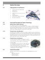
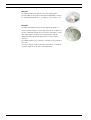
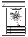
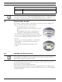
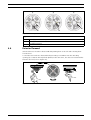
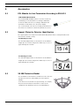
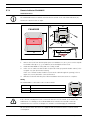
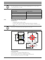
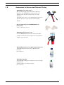
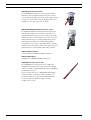
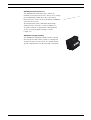
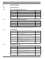
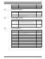
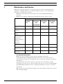
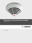
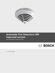
Conventional Automatic Detectors
FCP-320/FCH-320
en
Operation Guide
Conventional Automatic Detectors
Table of Contents | en
3
Table of Contents
1
Product Description
5
2
System Overview
6
2.1
Configuration of the Detector
6
2.2
Functional Description of Sensor Technology
6
2.2.1
Optical Sensor (Smoke Detector)
6
2.2.2
Thermal Sensor (Heat Detector)
6
2.2.3
Chemical Sensor (Gas Sensor)
6
2.3
System Description
6
2.4
Features
7
3
Planning
8
3.1
Basic Planning Guidelines
8
3.2
Use in Fire Barriers Conforming to DIBt
8
4
Installation
9
4.1
Overview of Detector Bases
4.2
Mounting the Bases
11
9
4.3
Wiring
12
4.3.1
Wiring the MS 400/MS 400 B
12
4.3.2
Wiring the MSR 320
13
4.4
Detector Base Sounder
14
4.5
Installing the Detector Head
14
4.6
Detector Removal
15
5
Accessories
16
5.1
EOL Module for Line Termination According to EN 54-13
16
5.2
Support Plates for Detector Identification
16
5.3
SK 400 Protective Basket
16
5.4
SSK 400 Protective Dust Cover
17
5.5
MK 400 Detector Console
17
5.6
MH 400 Detector Heating Element
17
5.7
External Detector Alarm Display / Remote Indicator
17
5.7.1
Remote Indicator FAA-420-RI
18
5.7.2
External Detector Alarm Display MPA
19
5.8
Accessories for Service und Detector Testing
21
6
Order Overview
24
6.1
Detector Variants
24
6.1.1
Detectors with 820 Ohm Alarm Resistor
24
6.1.2
Detectors with 470 Ohm Alarm Resistor*
24
6.2
Detector Bases
24
6.3
Detector Accessories
24
6.4
Installation Accessories
25
6.5
Detector Base Sounders
25
Bosch Sicherheitssysteme GmbH
Operation Guide
F.01U.002.707 | 8.0 | 2011.10
4
en | Table of Contents
Conventional Automatic Detectors
6.6
Service Accessories
25
7
Maintenance and Service
26
7.1
Coding of the Detector Types
27
7.2
Test Procedure for Detectors with C-Sensor
27
7.3
Test Procedure for Detectors without C-Sensor
28
7.4
Warranty
28
7.5
Repair
28
7.6
Disposal
28
7.7
Additional Documentation
28
8
Specifications
29
I
Abbreviations
31
F.01U.002.707 | 8.0 | 2011.10
Operation Guide
Bosch Sicherheitssysteme GmbH
Conventional Automatic Detectors
1
Product Description | en
5
Product Description
NOTICE!
This Product Information describes the entire product range of the FCP-320/FCH-320
Conventional Automatic Fire Detectors.
The FCP-320/FCH-320 Conventional Automatic Fire Detectors works on the basis of the
conventional technology and combines standard detection methods such as scattered light
measurement and temperature measurement with gas measuring technology at the highest
configuration level.
This method uses state-of-the-art processing methods to evaluate the signals from the gas
sensor and scattered light sensor or thermal sensor.
Security against false alarms is thus increased significantly and detection time is reduced in
comparison with the fire detectors generally available on the market today.
Thanks to the higher information content of the multisensor detectors, the use of detectors is
possible in environments where pure smoke detectors cannot be used.
The detectors are available in the following configuration levels:
–
FCP-OC320: Combined optical, gas-sensitive smoke detectors
–
FCP-OT320: Combined optical, thermal smoke detectors
–
FCP-O320: Optical smoke detectors
–
FCH-T320: Thermal detectors.
The detector's timeless and innovative design is a result of the cooperation between
engineers and designers. With this design it is possible to reconcile the contradictory goals of
a generous installation space and a small detector.
The placement of the individual display on the detector tip is the first externally visible
characteristic of the installation-friendly development concept. The stable and robust
detector base need no longer be aligned due to the position-independent position of the
individual display.
It is suitable for surface and flush mounting and includes separate mounting points for
dropped ceiling and concealed sockets. In addition, it fits all common bore patterns. For
surface mounting, the cable may be fed through on the side.
The integrated strain relief for interfloor cables prevents the removal of cables from the
terminal after installation. The terminals are easily accessible; a retainer for the end of line
resistor is integrated. Cable diameters of up to 2.5 mm2 can be used.
It can be equipped with a damp room seal so that all installation requirements can be covered
with one base.
The 320 Series detectors are available with either a 420 Ω alarm resistor or a 320 Ω alarm
resistor. The operating voltage range is 8.5 V DC to 32 V DC, which allows the detectors to be
used with almost every common conventional fire panel.
Bosch Sicherheitssysteme GmbH
Operation Guide
F.01U.002.707 | 8.0 | 2011.10
6
en | System Overview
Conventional Automatic Detectors
2
System Overview
2.1
Configuration of the Detector
1
Smoke measurement chamber with
2
Thermal sensor
3
Chemical sensor (covered on the cross-
3
4
optical sensor
2
1
section)
4
Individual display
5
PC board with evaluation electronics
6
MS 400 / MS 400 B Base
6
5
Figure 2.1 Configuration of the Detector
2.2
Functional Description of Sensor Technology
2.2.1
Optical Sensor (Smoke Detector)
The optical sensor uses the scattered-light method.
An LED sends light into the measuring chamber (refer to Figure 2.1, item 1); this light is
absorbed by the labyrinth structure. In the event of a fire, smoke enters the measuring
chamber. The light is scattered by the smoke particles and hits the photo diodes, which
transform the quantity of light into a proportional electrical signal.
2.2.2
Thermal Sensor (Heat Detector)
A thermistor (refer to Figure 2.1, item 2) in a resistance network is used as a thermal sensor;
an analog-digital converter measures the temperature-dependent voltage at regular intervals.
Depending on the detector class set, the temperature sensor switches to an alarm state if the
maximum temperature exceeds 54 °C (thermal maximum) or a defined temperature increase
within a particular timeframe (thermal differential).
2.2.3
Chemical Sensor (Gas Sensor)
The gas sensor (refer to Figure 2.1 and Figure 2.2, item 3)
detects mainly the carbon monoxide (CO) that is produced
by a fire, but it also detects hydrogen (H) and nitrogen
monoxide (NO).
The underlying measurement principle is CO oxidation and
the measurable current that it creates. The sensor signal
3
value is proportional to the concentration of gas.
The gas sensor supplies additional information in order to
reliably suppress deception variables.
2.3
Figure 2.2 Chemical Sensor
System Description
Up to two detection principles are integrated into the FCP-320/FCH-320 Series Fire
Detectors:
–
Optical (for smoke): O
–
Thermal (for heat): T
–
Chemical (for gas): C
F.01U.002.707 | 8.0 | 2011.10
Operation Guide
Bosch Sicherheitssysteme GmbH
Conventional Automatic Detectors
System Overview | en
7
All sensor signals are analyzed continually by the internal signal analysis electronics and are
linked with each other. If a signal combination fits the detector’s programmed code field, an
alarm is automatically triggered.
By linking the sensors (combined detectors), the detector can also be used in places where
the work carried out gives rise to light smoke, steam or dust.
The FCP-OC320/FCP-OC320-R470 detectors analyze the present CO concentration and adjust
the threshold of the optical sensor in accordance with the CO concentration. If no CO is in the
air, the alarm is triggered nonetheless at a certain level of smoke density and above. However,
the alarm is not triggered if only CO is detected in the air.
The FCP-OT320/FCP-OT320-R470 detectors trigger an alarm in the case of smoke as well as in
the case of a temperature rise. Additionally, the threshold of the optical sensor is adjusted in
accordance with the absolute temperature and the rate of temperature rise.
2.4
Features
–
Active adjustment of the threshold (drift compensation) if the optical sensor becomes
contaminated.
–
Active adjustment of the threshold (drift compensation) of the chemical sensor.
–
Activation of a remote external detector alarm display is possible.
–
Optional mechanical removal safeguard (can be activated/deactivated).
–
Dust-resistant labyrinth and cap construction.
–
Every detector base has a “Chamber Maid Plug” (a cleaning opening with a plug) for
blowing out the optical chamber with compressed air (not required for the FCH-T 320/
FCH-T 320-R470/FCH-T 320-FSA Heat Detectors).
–
Connectable to Bosch fire panels and the majority of conventional fire panels available on
the market.
–
Two variants with 820 Ω alarm resistor and 470 Ω alarm resistor enables the detector
application with nearly all conventional fire panels.
–
An unscreened cable may be used for the primary line.
Bosch Sicherheitssysteme GmbH
Operation Guide
F.01U.002.707 | 8.0 | 2011.10
8
3
en | Planning
Conventional Automatic Detectors
Planning
NOTICE!
FCP-320/FCH-320 Conventional Automatic Fire Detectors are not designed for exterior use.
3.1
Basic Planning Guidelines
–
The planning of multisensor fire detectors takes place according to the guidelines for
optical detectors, until an independent guideline has been worked out with the VdS (see
DIN VDE 0833 Part 2 and VDS 2095):
–
–
–
Maximum monitoring area 120 m2
–
Maximum installation height 16 m.
Maximum permitted air speed: 20 m/s.
A maximum of 32 detectors can be connected per primary line. This number is limited to
20 detectors when connected to an UGM 2020 (GIF/GIF2).
3.2
Use in Fire Barriers Conforming to DIBt
The FCH-T320-FSA and FCP-O320 are available for use in fire barriers conforming to the
guideline of the DIBt (Deutsches Institut für Bautechnik/German Institute for Building
Technology).
When planning for fire barriers conforming to DIBt, the FCH-T 320-FSA detector must be set
to class A1R.
Both models have DIBt approval.
F.01U.002.707 | 8.0 | 2011.10
Operation Guide
Bosch Sicherheitssysteme GmbH
Conventional Automatic Detectors
Installation | en
4
Installation
4.1
Overview of Detector Bases
9
The FCP-320/FCH-320 Series detector head is used in one of the following listed detector
bases, which are suitable for both flush-mounted and surface-mounted cable feed. They have
separate attachment points for ceiling mount/flush-mounted back boxes. In addition, they fit
all standard bore patterns.
The detector bases are made from white ABS plastic (color similar to RAL 9010) and have a
matte surface finish.
The bases have screw terminals for connection of the detector and its accessories to the fire
panel. Contacts connected with the terminals provide for a secure electrical connection when
mounting the FCP-320/FCH-320 detector heads. Cables up to 2.5 mm2 can be used.
To protect against unauthorized removal, the detector head can be secured with a variable
locking.
MS 400
The MS 400 Detector Base is the standard detecor base. It has
seven screw terminals.
MSF 400 B
The standard MS 400 Detector Base with Bosch-branding.
FAA-420-SEAL
Seal for using the MS 400 and MS 400 B detectors in a humid
environment. The TPE seal protects the detector reliably
against the penetration of condensed water.
Bosch Sicherheitssysteme GmbH
Operation Guide
F.01U.002.707 | 8.0 | 2011.10
10
en | Installation
Conventional Automatic Detectors
MSR 320
The MSR 320 Conventional Detector Base with Relay is
provided with an integrated relay that has NO/C/NC contacts
for switching applications (e. g. dampers, door holders, etc.).
MSC 420
The MSC 420 Additional Base was designed specially for
surface mounted cable feed via cable protection conduits. It is
used in combination with any of the above listed bases. It has
two opposing pre-cut inlets of 20 mm diameter and two
additional opposing and prepared inlets for up to 28 mm
diameter.
The additional base has a diameter of 120 mm and a height of
36.7 mm.
To protect against condensed water penetration, a seal made
of TPE is situated on the base of the MSC 420.
F.01U.002.707 | 8.0 | 2011.10
Operation Guide
Bosch Sicherheitssysteme GmbH
Conventional Automatic Detectors
4.2
Installation | en
11
Mounting the Bases
The detector bases are screwed to the even, dry surface using two screws approx. 55 mm
apart.
In the case of cable feed for surface mounting, break out the prepared entry points (X) on the
housing.
In the case of flush mounted cable feed, route the cable through the opening in the centre of
the base.
The short mounting bores marked in the sketch with “Y” may be used only for fixing over a
back box.
NOTICE!
Cable feed and outfeed can be on the same side.
For cable feed at the FAA-420-SEAL and MSC 420 puncture the sealing with a pointed tool. Do
not cut the sealing with a knife.
Ø 120
14
7.8
22.7
X
Ø 100
55
Y
Y
Bosch Sicherheitssysteme GmbH
Operation Guide
F.01U.002.707 | 8.0 | 2011.10
12
en | Installation
4.3
Conventional Automatic Detectors
Wiring
NOTICE!
Keep screening wire as short as possible and insulate it.
4.3.1
Wiring the MS 400/MS 400 B
b1
b2
}
LSN +/L..b
max. 30 V DC
bk
ye
rd
wh
bk
a1/a2
(LSN -/L..a)
ye
gn
C
max. 3 m
bk rd
+
MPA/
FAA-420-RI
–
Legend
ye
yellow, connects to b1/b2 + / L..b (conventional)
wh
white, connects to a1/a2 - / L..a (conventional)
rd
red, connects to +V
bk
black, connects to 0V
gn
green, connects to shielding wire
c
Indicator output
+V / 0V
Terminals for looping through the power supply to subsequent elements
MPA / FAA-420-
External Detector Alarm Display / Remote Indicator
RI
F.01U.002.707 | 8.0 | 2011.10
Operation Guide
Bosch Sicherheitssysteme GmbH
Conventional Automatic Detectors
Installation | en
13
NOTICE! The last detector in a conventional line can be terminated either with a terminal
resistor in the detector base or with an FLM-320-EOL2W EOL module. For terminating the line
according to the EN-54-13 standard, the FLM-320-EOL2W EOL module is required.
4.3.2
Wiring the MSR 320
Maximum contact load (resistive load) of the change-over relay:
–
62.5 VA: 0.5 A at 125 V AC
–
30 W: 1 A at 30 V DC
0,5 A / 125 V AC
1 A / 30 V DC
NC NO
FLM-420/4-CON
CZM
} OUT +
COM
b2
NC
C
b1
NO
ye
ye
rd
wh
bk
gn
c
C
max. 3 m
a1/a2
–
FLM-420/4-CON
CZM
} OUT –
bk
rd
+
MPA/
FAA-420-RI
Legend
ye
yellow, connects to b1/b2 + / L..b (conventional)
wh
white, connects to a1/a2 - / L..a (conventional)
rd
MPA/FAA-420-RI: red, connects to b1
bk
MPA/FAA-420-RI: black, connects to c (Indicator output)
gn
green, connects to shielding wire
NC / C / NO
Changeover relay (for the MSR 320 only)
Bosch Sicherheitssysteme GmbH
Operation Guide
F.01U.002.707 | 8.0 | 2011.10
14
en | Installation
Conventional Automatic Detectors
Legend
+V / 0V
Terminals for looping through the power supply to subsequent elements
MPA / FAA-420-
External Detector Alarm Display / Remote Indicator
RI
NOTICE! The last detector in a conventional line can be terminated either with a terminal
resistor in the detector base or with an FLM-320-EOL2W EOL module. For terminating the line
according to the EN-54-13 standard, the FLM-320-EOL2W EOL module is required.
4.4
Detector Base Sounder
Detector base sounders, available in four variants, are used if the acoustic signaling of an
alarm is required directly at the location of the fire.
–
MSS 300 Detector Base Sounder white, for
conventional technology, connection via the detector C
point.
–
MSS 300 WS-EC Detector Base Sounder white, for
conventional technology, with external activation.
The integrated tone generator has 11 tones for selection
(incl. tones according to DIN 33404 and EN 457) with sound
pressure of max. 100 dBA, depending on the type of tone
selected.
The tone type on conventional variants is set via four DIP
switches and the volume adjusted continuously via a
potentiometer.
Surface mounted and flush mounted cable feed are
possible.
4.5
Installing the Detector Head
NOTICE!
The packaging for the multisensor detector with C sensor consists of tear-proof PE-ALU
laminated film and must be cut open carefully.
After installation and connection of the base, the detector head is set into the base and
turned to the right as far as it will go.
Detector bases are delivered with inactive locks.
The detector head can be locked into the base (removal protection). The locking feature is
activated by breaking the bolt (X) out of the base and pushing it into the corresponding guide,
as shown in Figure 4.1.
F.01U.002.707 | 8.0 | 2011.10
Operation Guide
Bosch Sicherheitssysteme GmbH
Conventional Automatic Detectors
Installation | en
1
2
15
3
X
X
X
X
Figure 4.1 Activating the Removal Protection
Legend
4.6
1
Bolt (X) prior to breaking out
2
Bolt (X) installed but inactive
3
Locking activated
Detector Removal
Unlocked detector heads are disassembled by turning them to the left and removing them
from the base.
Locked detector heads are disassembled by inserting a screwdriver into the unlocking
opening (Y) so that the bolt is pushed upward; at the same time, the detector head should be
turned to the left (refer to Figure 4.2).
Y
Figure 4.2 Detector Removal (Locked Detector)
Bosch Sicherheitssysteme GmbH
Operation Guide
F.01U.002.707 | 8.0 | 2011.10
16
en | Accessories
Conventional Automatic Detectors
5
Accessories
5.1
EOL Module for Line Termination According to EN 54-13
FLM-320-EOL2W EOL-Modul
The FLM-320-EOL2W EOL module is a 2-wire moduel for
terminating a conventional line according to EN 54-13.
It detects faults in the line according to EN 54-13 and
transmits a notification to the fire panel display.
For a conventional connection according to EN 54-13 one
line must not contain more than 32 automatic detectors.
5.2
Support Plates for Detector Identification
The support plates are made from 1.8mm thick ABS plastic and are clamped between the
detector base and the ceiling.
TP4 400 Support Plate
The TP4 400 Support Plate is intended for an installation
height up to 4 m and is designed for labels up to a size of
approximately 65 x 34 mm.
15 / 4
TP8 400 Support Plate
The TP8 400 Support Plate is intended for an installation
height up to 8 m and is designed for labels up to a size of
approximately 97 x 44 mm.
5.3
SK 400 Protective Basket
The SK 400 Protective Basket is installed over the detector
and gives the detector substantial protection against
damage.
If the detector is mounted in a sports facility, for example,
the protective basket prevents balls or other sports
equipment from hitting the detector and damaging it.
F.01U.002.707 | 8.0 | 2011.10
Operation Guide
Bosch Sicherheitssysteme GmbH
Conventional Automatic Detectors
5.4
Accessories | en
17
SSK 400 Protective Dust Cover
The SSK 400 Protective Dust Cover is necessary during
construction work to protect an installed detector base,
with or without upper detector section, from
contamination. The protective dust cover made from
polypropylene (PP) is pushed onto the installed detector
base.
5.5
MK 400 Detector Console
The MK 400 Detector Console is used to install detectors
above door frames or similar in compliance with DIBt.
The console is supplied with a pre-mounted MS 400
Detector Base (the detector shown is not included in the
scope of delivery).
5.6
MH 400 Detector Heating Element
The MH 400 Detector Heating Element is required if the
detector is used in an environment where water
condensation can occur, such as in a warehouse that must
frequently be opened briefly for delivery vehicles.
The detector heating element is connected to the + V/0 V
terminals in the detector base.
Operating voltage: 24 V DC
Resistor: 1 kΩ
Power consumption: 3 W.
The heating is supplied with power either by the loopedthrough supply voltage via the control panel or by a
separate power supply unit.
With supply via the control panel, the number of detector
heating elements depends on the cable cross section and
cable length used.
5.7
External Detector Alarm Display / Remote Indicator
An External Detector Alarm Display or Remote Indicator is required if the detector is not
directly visible or has been mounted in false ceilings or floors.
The remote indicators should be installed in corridors or access pathways to the
corresponding building sections or rooms. The red alarm indication of both FAA-420-RI and
MPA correspond to DIN 14623.
Bosch Sicherheitssysteme GmbH
Operation Guide
F.01U.002.707 | 8.0 | 2011.10
18
en | Accessories
5.7.1
Conventional Automatic Detectors
Remote Indicator FAA-420-RI
Installation Notes
NOTICE!
The FAA-420-RI must be installed such that the broad side of the red alarm indication (A)
follows the observer’s line of sight.
51
1.
57
FAA-420-RI
X
_+
79
A
Y
31
2.
79
Z
A
Figure 5.1 Mounting the FAA-420-RI
1.
Remove the hood from the baseplate prior to installation. To do so, press on the snap-fit
hook with a flat object (e. g. screwdriver) and carefully lift off the hood.
2.
Install the FAA-420-RI on a dry and even ceiling or wall.
3.
In the case of surface mounted cable feed, break off the pre-punched cable entries (refer
to Figure 5.1, item Z) from the housing.
In the case of flush mounted cable feed, insert the cable through the opening (refer to
Figure 5.1, item Y) below the connection board.
4.
Refit the hood and click into place when installation and connection are complete.
Wiring
The FAA-420-RI is connected to two screw terminals.
Terminal
Connector
-
GLT - / LSN -
+
GLT + / LSN +
_+
CAUTION!
If the current consumption for the connected detector exceeds 20 mA, it can lead to the
malfunction of or damage to the FAA-420-RI Remote Indicator.You should restrict the
maximum detector current consumption to 20 mA to avoid damaging the FAA-420-RI.
All current Bosch fire detectors are equipped with an internal resistor to restrict current
consumption.
F.01U.002.707 | 8.0 | 2011.10
Operation Guide
Bosch Sicherheitssysteme GmbH
Conventional Automatic Detectors
Accessories | en
19
NOTICE!
The cable length between the detector and the FAA-420-RI must not exceed 3 m when
connected by an unscreened cable.
Technical Specification FAA-420-RI
5.7.2
Operating voltage
5 V DC to 30 V DC
Maximum current consumption
20 mA
Display medium
2 LEDs
Permissable wire gauge
0.6 mm to 2 mm
Dimensions
79 x 79 x 31 mm
Weight
approx. 45 g
External Detector Alarm Display MPA
Installation Notes
–
Installation directly onto wall or ceiling.
–
For surface cable feed break out the prepared inlets (X) at the housing wall.
–
For rear entry, conduit box mounting, feed the cable through the opening in the base
center.
NOTICE!
The flat side of the prism (Y) must show in direction of the viewer.
85
60
85
55
A
1234
Y
39
55
X
11
A
Y
Figure 5.2 Mounting the MPA
Connecting the MPA
The MPA will be connected to the Wago-clamps 1 to 4.
Connect: Put in the isolated wire (no braid) into the clamp.
Disconnect: Pull the wire out of the clamp by turning it back and forth.
You can connect up to four detectors onto each MPA.
Bosch Sicherheitssysteme GmbH
Operation Guide
F.01U.002.707 | 8.0 | 2011.10
20
en | Accessories
Conventional Automatic Detectors
Three inputs (terminal 2 to terminal 4) allow the adaptation to the different line technologies.
Connection on reliance to the used line technology
Line Technology
Fire Panel
Terminals Used
Conventional
BZ 1060
1+2
Conventional
FPA-5000, UEZ 1000, UGM 2020, FP 102/104/106
1+3
FPA-5000, BZ 500 LSN, UEZ 1000, UEZ 2000 LSN,
1+4
LSN
UGM 2020
Terminal
Connector
1
Ground
2
Input flashing (LED flashes)
3
Input static (LED steady on)
4
Input static (LED steady on)
Connect onto terminal 4 only via pre resistor, otherwise the LED could
be destroyed.
1234
All current Bosch fire detectors are equipped with an internal resistor
to restrict current consumption.
CAUTION!
If the current consumption for the connected detector exceeds 20 mA, it can lead to the
malfunction of or damage to the MPA External Detector Alarm Display. You should restrict the
maximum detector current consumption to 20 mA to avoid damaging the FAA-420-RI.
NOTICE!
The cable length between the detector and the MPA must not exceed 3 m when connected by
an unscreened cable.
Technical Specifications MPA
Operating voltage
9 V DC to 30 V DC
Maximum current consumption
–
Terminal 2
–
approx. 2 mA
–
Terminal 3
–
limited to 13 mA
–
Terminal 4
–
limit to maximum 20 mA
Display medium
1 LED
Permissable wire gauge
0.6 mm to 0.8 mm
Dimensions
79 x 79 x 31 mm
Weight
approx. 65 g
VdS approval number
G 294 052
F.01U.002.707 | 8.0 | 2011.10
Operation Guide
Bosch Sicherheitssysteme GmbH
Conventional Automatic Detectors
5.8
Accessories | en
21
Accessories for Service und Detector Testing
SOLO200 Detector Removal Tool
With its pivoting grip segments and three different
diameters, the SOLO200 Detector Removal Tool is
suitable for the insertion and removal of most fire
detectors.
The plastic caps ensure secure gripping of fire detectors
and thus also protect the detector surface against
damage.
RTL-cap Plastic Caps for the SOLO200 Detector
Removal Tool
Scope of delivery = 2 pieces
SOLO330 Smoke Detector Tester
Use the SOLO330 Smoke Detector Tester for in place
testing of smoke detectors using an aerosol designed to
simulate smoke particles.
SOLO A3-001 Test Aerosol for Optical Smoke Detectors
Spray with 250 ml Test Aerosol for Optical Smoke
Detectors
DU = 12 pieces
SOLO CO Testing Gas
Spray with CO testing gas for multisensor detectors with
C component.
Contents: approx. 4 l compressed gas
DU = 12 pieces
Bosch Sicherheitssysteme GmbH
Operation Guide
F.01U.002.707 | 8.0 | 2011.10
22
en | Accessories
Conventional Automatic Detectors
SOLO461 Heat Detector Tester
The SOLO461 Heat Detector Tester operates with a
battery to direct heated air at heat detector sensors.
It uses a patented CAT™ (Cross Air Technology) system
to focus the air and direct it horizontally at the sensor
regardless of the detector's size or shape.
FME-TESTIFIRE Multi-Stimulus Detector Tester
The FME TESTIFIRE is the first functional test tool for
optical and ionization fire detectors, heat detectors
(fixed temperature and rate-of-rise), carbon monoxide
(CO) detectors, as well as multi sensor detectors and
multi criteria detectors. Testing stimuli (heat, smoke,
and carbon monoxide) are created without using
pressurized aerosol cans or hazardous media. Testing
stimuli are generated at the time of test using safe and
patented processes fuelled by replaceable capsules.
FME-TS3 Smoke Capsule
Smoke Capsule for FME-TESTIFIRE testing tool
FME-TC3 CO Capsule
CO Capsule for FME-TESTIFIRE testing tool
SOLO100 Telescopic Access Pole
The SOLO100 Telescopic Access Pole enables the
installation and replacement of fire detectors at high
ceilings. It can be expanded with up to three SOLO101
Fixed Extension Poles.
The Telescopic Access Pole withstands high voltage
situations and is checked for Safety compliance in
accordance with the requirements of BS EN 61235
Section 12 using an applied voltage of 20 kV.
Length: 1 m to 3.4 m
F.01U.002.707 | 8.0 | 2011.10
Operation Guide
Bosch Sicherheitssysteme GmbH
Conventional Automatic Detectors
Accessories | en
23
SOLO101 Fixed Extension Pole
The SOLO101 Fixed Extension Pole enables the
installation and replacement of fire detectors at ceilings.
Use it individually or with up to three other Fixed
Extension Poles. It also can be used with the SOLO100
Telescopic Access Pole.
The Fixed Extension Pole withstands high voltage
situations and is checked for safety compliance in
accordance with the requirements of BS EN 61235
Section 12 using an applied voltage of 20 kV.
Length: 1 m
SOLO610 Test Equipment Bag
The SOLO610 Test Equipment Bag is made of sturdy
woven polyester with a PVC coating for carrying and
storing test and service products. It is designed with
special compartments to hold a full range of products.
Bosch Sicherheitssysteme GmbH
Operation Guide
F.01U.002.707 | 8.0 | 2011.10
24
en | Order Overview
Conventional Automatic Detectors
6
Order Overview
6.1
Detector Variants
6.1.1
Detectors with 820 Ohm Alarm Resistor
Type Number
Designation
Product ID
FCP-OC320
Multisensor Detector Optical/Chemical
F.01U.026.292
FCP-OT320
Multisensor Detector Optical/Thermal
F.01U.026.295
FCP-O320
Optical Smoke Detector
F.01U.026.293
FCH-T320
Heat Detector
F.01U.026.291
Heat Detector for Fire Barriers conforming to DIBt,
F.01U.026.294
FCH-T320-FSA
Quality-controlled
6.1.2
Detectors with 470 Ohm Alarm Resistor*
Type Number
Designation
Product ID
FCP-OC320-R470
Multisensor Detector Optical/Chemical
F.01U.029.867
FCP-OT320-R470
Multisensor Detector Optical/Thermal
F.01U.029.862
FCP-O320-R470
Optical Smoke Detector
F.01U.029.857
FCH-T320-R470
Heat Detector
F.01U.029.861
Detectors with 470 Ohm Alarm Resistors are not available in all countries.
6.2
Detector Bases
Type Number
Designation
Product ID
MS 400
Standard Detector Base for surface-mounted and
4.998.021.535
flush-mounted cable feed
MS 400 B
Standard Detector Base for surface-mounted and
F.01U.215.139
flush-mounted cable feed, with Bosch-branding
FAA-420-SEAL
Damp Room Seal for the MS 400 and MS 400 B
F.01U.215.142
Detector Bases
MSR 320
Conventional Detector Base with Relay for surface-
4.998.114.565
mounted and flush-mounted cable feed
MSC 420
Additional Base with Damp Room Seal, for surface-
4.998.113.025
mounted cable feed
6.3
Detector Accessories
Type Number
Designation
Product ID
FLM-320-EOL2W
EOL Module 2-Wire
F.01U.083.619
TP4 400
Support Plate for Detector Identification up to 4 m
4.998.084.709
installation height (1 pack = 50 pieces)
TP8 400
Support Plate for Detector Identification up to 8 m
4.998.084.710
installation height (1 pack = 50 pieces)
SK 400
Protective Basket, to protect against mechanical
4.998.025.369
damage
F.01U.002.707 | 8.0 | 2011.10
Operation Guide
Bosch Sicherheitssysteme GmbH
Conventional Automatic Detectors
6.4
Order Overview | en
25
Type Number
Designation
Product ID
SSK 400
Protective Dust Cover (1 pack = 10 pieces)
4.998.035.312
MH 400
Detector Heating Element
4.998.025.373
Installation Accessories
Type Number
Designation
Product ID
MK 400
Detector Console, for DIBt compliant mounting of
4.998.097.924
detectors above doors etc., including detector base
FMX-DET-MB
Mounting Bracket, with mounting material for false
2.799.271.257
floors, without detector base
6.5
Detector Base Sounders
Type Number
Designation
Product ID
MSS 300
Detector Base Sounder White,
4.998.025.372
only C point activation via attached detector, for
surface-mounted and flush-mounted cable feed
MSS 300 WS-EC
4.998.120.501
Detector Base Sounder White,
only for separate activation e.g. via Interface Module,
for surface-mounted and flush-mounted cable feed
6.6
Service Accessories
Type Number
Designation
Product ID
SOLO200
Detector Removal Tool
4.998.112.113
RTL-cap
Plastic Caps for the SOLO200 Detector Removal Tool
4.998.082.502
(Scope of delivery = 2 pieces)
SOLO330
Smoke Detector Tester
4.998.112.071
SoloA3-001
Test Aerosol for Optical Smoke Detectors
4.998.112.074
Solo CO testgas
Solo CO Testing Gas (400 ml, 1 pack = 10 pieces)
4.998.109.056
SOLO461
Heat Detector Tester (wireless)
4.998.112.072
SOLO720
Battery for SOLO461 Heat Detector Tester
4.998.147.576
FME-TESTIFIRE
Multi-Stimulus Testing Tool
F.01U.143.407
FME-TS3
Smoke Capsule
F.01U.143.404
FME-TC3
CO-Capsule
F.01U.143.405
SOLO100
Telescopic Access Pole
4.998.112.069
SOLO101
Fixed Extension Pole
4.998.112.070
SOLO610
Test Equipment Bag
4.998.112.073
Bosch Sicherheitssysteme GmbH
Operation Guide
F.01U.002.707 | 8.0 | 2011.10
26
7
en | Maintenance and Service
Conventional Automatic Detectors
Maintenance and Service
Maintenance and inspection work on security systems are governed in Germany by the
regulations of DIN VDE 0833; these regulations stipulate reference to the manufacturer's
instructions for maintenance intervals.
–
Maintenance and inspection work should be carried out regularly and by trained
personnel.
–
BOSCH ST recommends a functional and visual inspection at least once a year.
Testing
Detector Type
FCP-O320
FCH-T320
FCP-OT320
FCP-OC320
FCP-O320-
FCH-T320-
FCP-OT320-
FCP-OC320-
R470
R470
R470
R470
FCH-T320-FSA
Check of the LED
X
X
X
X
X
X
X
X
X
X
X
X
X
X
X
X
-
X
X
X
X
-
X
X
-
-
-
X
display
Visual check of the
mounting
Visual check for
damage
Check the monitoring
range has not been
restricted, for
instance by shelves
or similar
installations.
Triggering with hot
air
Triggering with Solo
A3-001 testing gas
Triggering with CO
testing gas
–
FCP-OC320/FCP-OC320-R470
Multisensor detectors with C sensors must be exchanged every 5 years.
An FCP-OC320 and FCP-OC320-R470 will deactivate its C sensor after 5 years of
operation due to the gas sensor's limited life cycle. The detector continues to function as
an O detector.
Depending on the system, there may be no message to the control panel, and the
deactivation of the C sensor is only noticed when the detector is tested. The FCP-OC320/
FCP-OC320-R470 should therefore be exchanged promptly before 5 years of operation
has elapsed.
–
Optical smoke detectors should, depending on the environmental conditions, be cleaned
and exchanged regularly.
F.01U.002.707 | 8.0 | 2011.10
Operation Guide
Bosch Sicherheitssysteme GmbH
Conventional Automatic Detectors
Maintenance and Service | en
27
Every detector bottom has a “Chamber Maid Plug”
(cleaning opening with a plug) for blowing out the
optical chamber with compressed air (not required for
the FCH-T320/FCH-T320-R470 Heat Detectors).
7.1
Coding of the Detector Types
With the exception of the FCP-O320 and FCP-O320-R470, every detector has a colored
detector type identification ring around the central individual display.
This facilitates inspection by service personnel.
Type Number
Color Code
FCP-OC320/
Blue
FCP-OC320-R470
FCP-OT320/
Black
FCP-OT320-R470
FCH-T320/
Red
FCH-T320-R470/
FCH-T320-FSA
FCP-O320/
-
FCP-O320-R470
7.2
Test Procedure for Detectors with C-Sensor
You must first test the optical unit of the FCP-OC320 with the test aerosol. Reset the detector
when you have released the O sensor. This switches the C sensor into revision mode for
15 minutes and it can then be tested. Since the aerosol test for the detectors works like a
disturbance signal, (very large sig-nal with very quick increase), the signal evaluation for
disturbance variables is brought to bear and alarm signaling occurs only after approx. one
minute.
1.
Position the Smoke Detector Tester on the FCP-OC320.
2.
Spray aerosol (1 to 2 seconds).
Do not remove the test device from the detector; the O sensor triggers only approx.
60 seconds after the application of the test aerosol.
3.
Reset detector.
This switches the detector to revision mode.
4.
Place CO Testing Gas bottle in the test device.
5.
Position test device on the detector.
6.
Apply CO gas for 1/2 to 1 second.
The C sensor triggers after approx. 20 seconds.
NOTICE!
In revision mode the chemical unit of the detector can be tested separately. A minimum CO
gas concentration of 30 to 35 ppm is required when the chemical sensor is tested. This is
guaranteed if the test is performed with the CO Test Gas bottle as described.
Bosch Sicherheitssysteme GmbH
Operation Guide
F.01U.002.707 | 8.0 | 2011.10
28
7.3
en | Maintenance and Service
Conventional Automatic Detectors
Test Procedure for Detectors without C-Sensor
1.
2.
Position the Smoke Detector Tester on the detector.
Spray aerosol (1 to 2 seconds).
Do not remove the test device from the detector; the O sensor triggers only approx.
30 seconds after the application of the test aerosol.
3.
Reset detector.
This switches the detector to revision mode.
4.
The thermal sensor of the FCP-OT320/FCP-OT320-R470 and all heat detectors is tested
with the test device for heat detectors.
7.4
Warranty
Defective detectors are exchanged free of charge in the case of a claim under the warranty.
7.5
Repair
In the event of a defect, the entire detector is exchanged.
7.6
Disposal
Unusable electrical and electronic devices/modules must not be disposed of
with normal household refuse. They must be disposed of in compliance with
the applicable regulations and directives (e. g. WEEE in Europe).
FCP-OC320 Packaging Film
The packaging bag used for multisensor detectors with C sensor consists of tear-resistant PEALU laminated film and may be disposed of with the household refuse.
Defective detectors are exchanged and should be disposed of in accordance with statutory
regulations.
7.7
Additional Documentation
NOTICE!
The latest Product Information and the Installation Guide for the device are available as a
downloadable PDF file at http://www.boschsecurity.com/emea/fire.
F.01U.002.707 | 8.0 | 2011.10
Operation Guide
Bosch Sicherheitssysteme GmbH
Conventional Automatic Detectors
8
Specifications | en
29
Specifications
Multisensor Detectors
Device Type
FCP-OC320/FCP-OC320-R470
Detection principle
FCP-OT320/FCP-OT320-R470
Combination of:
Combination of:
–
Scattered light measurement
–
Scattered light measurement
–
Combustion gas measurement
–
Measurement of absolute
temperature and temperature
increase
Special features
–
Drift compensation of the optical
–
sensor and the gas sensor
Operating voltage
sensor
8.5 V DC to 30 V DC
Current consumption
< 0.12 mA
Individual display
LED red
Alarm output
Current increase (alarm resistor approx. 820 Ω or 470 Ω)
Indicator output
Response sensitivity (basic
Drift compensation of the optical
Open collector, connects through 0 V via 3.92 kΩ, max. 8 mA
–
data)
–
Optical sensor:
< 0.15 dB/m (EN54-7)
< 0.15 dB/m (EN54-7)
–
Optical sensor:
Chemical sensor: ppm range
–
Thermal sensor: Class A2R acc. to
EN 54-5
–
Thermal maximum unit:
> 54 °C
–
Thermal differential unit:
refer to table Page 30
Max. monitoring range
120 m2 (observe VdS guidelines)
Maximum installation height
16 m (observe VdS guidelines)
Permissible air speed
Permissible operating temp.
20 m/s
-10 °C . . . +50 °C
-20 °C . . . +50 °C
Permissible relative humidity
< 95% (non-condensing)
Protection category according
IP 40
to EN 60529
Color code
IP 43 with detector base with damp room seal
Blue ring
Black ring
Dimensions without base
circumference 99,5 x 52 mm
Dimensions with base
circumference 120 x 63,5 mm
Housing material / color
Weight without packaging
Weight with packaging
Product ID
Bosch Sicherheitssysteme GmbH
ABS / white, similar to RAL 9010, matte surface
approx. 80 g
approx. 75 g
approx. 125 g
approx. 115 g
F.01U.026.292/F.01U.026.867
F.01U.026.295/F.01U.026.862
Operation Guide
F.01U.002.707 | 8.0 | 2011.10
30
en | Specifications
Conventional Automatic Detectors
Smoke and Heat Detectors
Device Type
FCP-O320/FCP-O320-
FCH-T320/
R470
FCH-T320-R470/
Detection principle
Special features
FCH-T320-FSA
Scattered light
Measurement of absolute temperature and
measurement
temperature increase
Drift compensation of
For Fire Barriers
optical sensor
conforming to DIBt,
Quality-controlled
Operating voltage
8.5 V DC to 30 V DC
Current consumption
< 0.12 mA
Individual display
LED red
Alarm output
Current increase (alarm resistor approx. 820 Ω or 470 Ω)
Indicator output
Open collector, connects through 0 V via 3.92 kΩ, max. 8 mA
Response sensitivity (basic
< 0.15 dB/m (EN54-7)
–
data)
–
Class A2R acc. to
–
–
Thermal max. unit:
Max. monitoring range
Thermal max. unit:
> 54 °C
> 54 °C
–
Class A1R acc. to
EN 54-5V
EN 54-5
–
Thermal diff. unit:
Thermal diff. unit:
refer to table
refer to table
Page 30
Page 30
120 m2 (observe VdS
40 m2 (observe VdS guidelines)
guidelines)
Maximum installation height
16 m (observe VdS
6 m (observe VdS guidelines)
guidelines)
Permissible air speed
20 m/s
Permissible operating temp.
-20 °C . . . +65 °C
Permissible relative humidity
-20 °C . . . +50 °C
< 95% (non-condensing)
Protection category according
IP 40
to EN 60529
IP 43 with detector base with damp room seal
Color code
-
Red ring
Dimensions without base
circumference 99,5 x 52 mm
Dimensions with base
circumference 120 x 63,5 mm
Housing material / color
ABS / white, similar to RAL 9010, matte surface
Weight without packaging
approx. 75 g
Weight with packaging
approx. 115 g
Product ID
F.01U.026.293/
F.01U.026.291/
F.01U.029.857
F.01U.029.861
F.01U.026.294
Response Sensitivity of the Thermal Differential Unit According to EN 54-5
Temperature Rate of
Response Time for Detectors in the
Response Time for Detectors in the
min-1]
Sensitivity Class A1R
Sensitivity Classes A2R
Rise [K
10
F.01U.002.707 | 8.0 | 2011.10
Lower Limiting
Upper Limiting
Lower Limiting
Upper Limiting
Value [min/sec]
Value [min/sec]
Value [min/sec]
Value [min/sec]
4 min 20 s
2 min
5 min 30 s
1 min
Operation Guide
Bosch Sicherheitssysteme GmbH
Conventional Automatic Detectors
Temperature Rate of
Rise [K min
-1]
Specifications | en
Response Time for Detectors in the
Response Time for Detectors in the
Sensitivity Class A1R
Sensitivity Classes A2R
Lower Limiting
Upper Limiting
Lower Limiting
Upper Limiting
Value [min/sec]
Value [min/sec]
Value [min/sec]
Value [min/sec]
20
30 s
2 min 20 s
1 min
3 min 13 s
30
20 s
1 min 40 s
40 s
2 min 25 s
I
31
Abbreviations
ABS
Acrylonitrile butadiene styrene
DIBt
Deutsches Institut für Bautechnik (German Institute for Building Technology)
DIN
Deutsches Institut für Normung e.V. (German Institute for Standardization)
EN
European Standard
GLT
Conventional technology
LED
Light Emitting Diode
LSN
Local SecurityNetwork
PI
Product information
PP
Polypropylene
UEZ
Universelle Europazentrale (Universal European Fire Panel)
UGM
Universelle Gefahrenmeldezentrale (Universal Security System)
VDE
Verband Deutscher Elektrotechniker e.V. (German Association for Electrical,
Electronic & Information Technologies)
VdS
VdS Schadenverhütung GmbH
OTC
Optical/Thermal/Chemical (gas)
OT
Optical/Thermal
O
Optical
T
Thermal
Bosch Sicherheitssysteme GmbH
Operation Guide
F.01U.002.707 | 8.0 | 2011.10
Bosch Sicherheitssysteme GmbH
Robert-Bosch-Ring 5
85630 Grasbrunn
Germany
www.boschsecurity.com
© Bosch Sicherheitssysteme GmbH, 2011