1
AT&T 7400B Data Module
User’s Guide
555-020-707
Issue 1
November 1989
TO ORDER COPIES OF THIS MANUAL
Call:
AT&T Customer Information Center on 800-432-6600
In Canada Call 800-255-1242
Write:
AT&T Customer Information Center
2855 North Franklin Road
P.O. Box 19901
Indianapolis, Indiana 46219
Order:
Document No. 555-020-707 Issue 1, November 1989
FCC Notice:
This equipment has been tested and found to comply with the limits for a Class A digital
device, pursuant to Part 15 of the FCC Rules. These limits are designed to provide
reasonable protection against harmful interference when the equipment is operated in a
commercial environment. This equipment generates, uses, and can radiate radio
frequency energy and, if not installed and used in accordance with the instruction
manual, may cause harmful interference to radio communications. Operation of this
equipment in a residential area is likely to cause harmful interference in which case the
user will be required to correct the interference at his own expense.
While reasonable efforts were made to ensure that the
information in this document was complete and
accurate at the time of printing, AT&T can assume no
responsibility for any errors.
Changes or corrections to the information contained in
this document may be incorporated into future reissues.
DEFINITY is a trademark of AT&T. Hayes is a registered trademark and Smartmodem is a trademark of
Hayes Microcomputer Products, Inc. Microsoft and MS-DOS are registered trademarks of Microsoft
Corporation. PROCOMM is a registered trademark of Datastorm Technologies, Inc. RELAY GOLD is a
registered trademark of Relay Communications, Inc. CROSSTALK is a registered trademark of Digital
Communications Associates. CompuServe is a registered trademark of H&R Block. Delphi is a registered
trademark of Delphi Systems, Inc. Dow Jones News is a registered trademark of Dow Jones & Company,
Inc. LEXIS/NEXIS are registered trademarks of Mead Data Central, Inc. Newsnet is a registered
trademark of Newsnet, Inc. Official Airline Guide is a registered trademark of the Reuben H. Donnelley
Corporation.
Copyright© 1989 AT&T
All Rights Reserved
Printed in U.S.A.
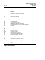
CONTENTS
PREFACE: ABOUT THIS GUIDE
Typographical Conventions
Organization of This Guide
Related Documentation
1
CHAPTER 1: INTRODUCTION
External Features
2
2-1
2-7
2-12
2-12
2-12
CHAPTER 3: FIRST TIME USERS
Operating Modes
Essential AT Commands
Sample Command Lines
A Sample On-Line Session
4
1-2
CHAPTER 2: INSTALLATION
Hardware and Software Requirements
Hardware Installation
Initial System Checks
If You Are Using a PC
If You Are Using a Dedicated Terminal
3
i
i
ii
3-1
3-2
3-4
3-6
CHAPTER 4: OPERATION AND CONFIGURATION
CONFIGURATION PARAMETERS
Operating Modes
Issuing Commands
From Data Mode to Command Mode and Back
Dialing a Number
Repeating a Command
Storing a Telephone Number
Automatic Answering
Remote Site Use
RESET AND CONFIGURATION RECALL
4-1
4-2
4-3
4-6
4-6
4-7
4-7
4-8
4-9
4-9
5
CHAPTER 5: TROUBLESHOOTING
How to Use This Chapter
A
APPENDIX A: AT COMMAND SET
B
APPENDIX B: S-REGISTERS
C
APPENDIX C: APPLICATION NOTES
PBX Application Notes
PC Applications Guide
Procomm Plus
Relay Gold
Crosstalk XVI
D
5-1
C-1
C-1
C-2
C-5
C-8
APPENDIX D: QUICK-REFERENCE SUMMARIES
GL GLOSSARY
PREFACE: ABOUT THIS GUIDE
DEFINITY Communications System
7400B Data Module
Page i
User’s Guide
PREFACE: ABOUT THIS GUIDE
The purpose of this guide is to provide information for installing,
operating, and maintaining the 7400B Data Module.
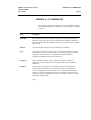
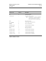
TYPOGRAPHICAL
CONVENTIONS
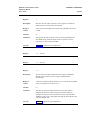
Throughout this guide, command lines that you type are shown in
typewriter-style characters, and responses that the 7400B Data Module
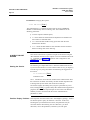
returns are shown in italics. The following is an example.
at h [ Enter ]
OK
Note the following characteristics of the display representation:
●
ORGANIZATION OF THIS
GUIDE
The first line is a command line as it should be typed. The [ Enter ]
symbol, when shown, indicates that you must press the Enter or
Return key to complete the command line.
●
Spaces are used to separate commands in some examples shown in
this guide. In actual use, the spaces may be typed, but they are not
required.
●
The second line in the example shows a typical response returned by
the data module.
The following paragraphs summarize the chapters and appendices
contained in this guide.
Chapter 1: Introduction. Discusses the basic operating features
of the AT&T 7400B Data Module and describes the external
indicators and connectors.
Chapter 2: Installation. Describes the hardware and software
required for installing the data module, and outlines procedures for
preparing the data module for operation.
Chapter 3: First Time Users. Provides some basics on 7400B
Data Module operation, describes how to use a few AT commands
that are essential for most data communications operations, and
then outlines a typical on-line session.
Chapter 4: Operation and Configuration. Describes how to
change, store, and recall configuration parameters, outlines how to
create and save custom, configuration profiles, and discusses more
advanced command usage with example command lines.
PREFACE: ABOUT THIS GUIDE
DEFINITY Communications System
7400B Data Module
User’s Guide
Page ii
Chapter 5: Troubleshooting. Describes procedures for
troubleshooting problems that may be encountered while
configuring and operating the 7400B Data Module.
Appendix A: AT Command Set. Contains an explanation of each
AT command accepted by the 7400B Data Module.
Appendix B: S-Registers. Contains an explanation of each Sregister used by the 7400B Data Module.
Appendix C: Application Notes. Contains notes on how to
configure some popular PC data communications software
packages for use with the 7400B Data Module, and provides a list
of application notes that describe how to administer specific AT&T
PBX systems for using the data module.
Appendix D: Quick-Reference Summaries. Contains quickreference summaries of AT commands, S-registers, result codes,
factory-default configuration settings, EIA-232-D connector pinouts, ASCII character set.
A glossary and an index are provided at the rear of this guide.
RELATED
DOCUMENTATION
The following is a list of other manuals that may provide helpful
information while installing and using the 7400B Data Module. Since
each user may have different equipment and software preferences or
availability, only generic titles are given for the manuals.
If you are using a terminal device other than a PC:
User's guide for your terminal device. You may need information
about the configuration and capabilities of your terminal device
from this manual during the installation and preliminary operation
of the 7400B Data Module.
If you are using a PC as your terminal:
User’s guide for Microsoft® MS-DOS®. You may need this
reference for explanations of commands used by your PC to install,
configure, and run your data communications software.
User's guide for your data communications software. You may need
this guide for information on how to configure your terminal
emulation software to access the 7400B Data Module.
DEFINITY Communications System
7400B Data Module
CHAPTER 1: INTRODUCTION
Page 1-1
User’s Guide
CHAPTER 1: INTRODUCTION
This chapter discusses the basic operating features of the 7400B Data
Module and describes the external indicators and connectors.
The data module provides an asynchronous data service link between a
Data Terminal Equipment (DTE) device and the following AT&T digital
PBX equipment:
●
DEFINITY™ Communications System Generic 1
●
DEFINITY Communications System Generic 2
●
System 75
●
System 85
Note:
Unless a specific DTE device is intended, the words terminal
device shall be used throughout this guide to represent any
applicable DTE device, including a dumb terminal, a printer,
a plotter, or a personal computer (PC) with an appropriate
data communications software package.
An EIA-232-D standard interface (formerly EIA recommended standard
RS-232-C) connects the terminal device to the 7400B Data Module, and
a standard Digital Communications Protocol (DCP) interface (using a
type D8W modular telephone cord) connects the data module to the
digital PBX.
An internal DIP-switch option allows the 7400B Data Module to be set
for use either with or without a telephone. In without-telephone mode,
the data module supports data service only, but in with-telephone mode
the data module provides simultaneous data and voice service (requires
an associated AT&T 7400-series DCP digital voice terminal).
Note:
If a 7400-series voice terminal with data features is used
with the 7400B Data Module, data service is provided by the
7400B Data Module and the data features of the voice
terminal cannot be used.
The 7400B Data Module uses a subset of the industry-standard AT
command set and supports transmission speeds of 300, 1200, 2400,
4800, 9600, and 19,200 bps.
Additional features of the 7400B Data Module, described in later
chapters of this manual, include:
●
non-volatile, read-write memory for storing two data options
profiles and up to four telephone numbers
●
automatic speed and parity adjustment
DEFINITY Communications System
CHAPTER 1: INTRODUCTION
7400B Data Module
User’s Guide
Page 1-2
●
data metering option
●
programmable control characters
●
self-test at start-up
●
local and remote loopback tests
●
test duration timers
●
voice terminal powered by the PBX is not affected if ac power
is removed from the 7400B Data Module
EXTERNAL FEATURES
The external features of the front and rear panels of the 7400B Data
Module and the separate power supply unit are described in this section.
The data module has a removable access panel on top of the unit, which
is described further in the hardware installation section of Chapter 2,
“Installation.”
Front Panel
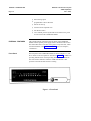
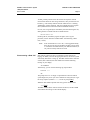
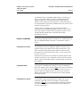
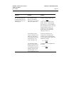
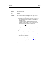
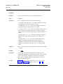
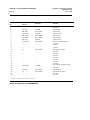
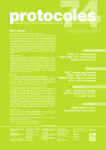
The front panel of the 7400B Data Module is shown in Figure 1-1, and
the 10 LEDs on the front panel are described in Table 1-1. In addition to
providing indications for normal operating modes, all of the LEDs are
also used as status indicators when the 7400B Data Module is first
powered on and the internal self-test is running.
Figure 1-1. Front Panel
DEFINITY Communications System
CHAPTER 1: INTRODUCTION
7400B Data Module
Page 1-3
User’s Guide
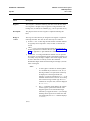
Connector
Description
POWER/
TEST
This red LED lights as long as power is applied to the data module. This LED
flashes during any test mode, except the start-up self-test. It also flashes along
with the DATA LED if the connection with the PBX is lost.
DATA
METERING
This red LED lights to indicate the state of the CTS (Clear To Send) output lead
when the Data Metering option is enabled.
AA
Automatic Answer. This red LED flashes to indicate an incoming call and
lights continuously when the data module is operating in Automatic Answer
mode.
CD
Carrier Detect. This red LED lights as long as communication is established
with the far end device.
RD
Receive Data. This red LED lights when received data is being transferred
from the 7400B Data Module to the local terminal device.
SD
Send Data. This red LED lights when transmitted data is being transferred from
the local terminal device to the 7400B Data Module.
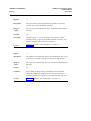
TR
Terminal Ready. If the &d0 option is enabled, the red LED is on continuously;
if either the &d1 or &d2 option is enabled, this LED indicates the state of the
DTR lead (see description of &d command in Appendix A).
OH
Off Hook. This red LED lights continuously from the time a data
communications call is initiated until the call is terminated.
CHECK
SPEED
This red LED lights when a call set up fails because of an incompatibility
between the configuration of the local terminal device and the far end device.
The incompatibility will usually occur if a common operating speed cannot be
achieved between the two endpoints. Chapter 5, “Troubleshooting,” provides
information about this and other conditions that may cause this LED to light.
DATA
This green LED lights to indicate that a data call is in progress. This LED
flashes along with the POWER/TEST LED if the connection with the PBX is
lost.
TABLE 1-1 Front Panel LED Indicator Descriptions
CHAPTER 1: INTRODUCTION
DEFINITY Communications System
7400B Data Module
User's Guide
Page 1-4
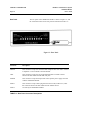
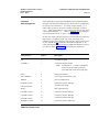
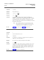
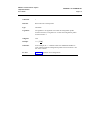
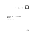
Rear Panel
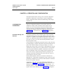
The rear panel of the 7400B Data Module is shown in Figure 1-2, and
the connectors located on the rear panel are described in Table 1-2.
Figure 1-2. Rear Panel
Connector
Description
PHONE
This connector accepts one end of the D8W telephone line cord used to connect
a telephone or voice terminal to the data module.
LINE
This connector accepts one end of the D8W telephone cord that connects
between the data module and the PBX wall jack.
POWER
This connector accepts the output cable of the separate power supply unit used
with the 7400B Data Module.
PORT 1
This connector accepts a male plug from the EIA-232-D (or RS-232-C) cable
that connects between the data module and the terminal device.
PORT 2
Not used by the 7400B Data Module.
TABLE 1-2 Rear Panel Connector Descriptions
CHAPTER 1: INTRODUCTION
DEFINITY Communications System
7400B Data Module
Page 1-5
User’s Guide
Power Supply Unit
A separate power supply unit is required with the 7400B Data Module.
This unit connects between a grounded AC outlet and the “POWER”
connector at the rear of the data module. This power supply unit
provides the necessary operating voltages for the data module.
Caution:
Make certain that the AC outlet to which you connect the
power supply is unswitched (for example, not controlled
by a wall switch or light dimmer).
Instructions for installing the power supply unit with an illustration are
provided in the hardware installation section of Chapter 2,
"Installation."
CHAPTER 2: INSTALLATION
DEFINITY Communications System
7400B Data Module
Page 2-1
User’s Guide
CHAPTER 2: INSTALLATION
This chapter describes the hardware and software required for installing
the data module, and outlines procedures for preparing the data module
for operation.
HARDWARE AND
SOFTWARE
REQUIREMENTS
In addition to the 7400B Data Module and the required separate power
supply, you will need the following items:
●
●
an asynchronous data terminal device or a personal computer
(PC) with data communications software
an EIA-232-D interface (formerly RS-232-C) cable to connect
between the terminal device and the data module
●
a type D8W telephone cord for Data Communications Protocol
(DCP) connection between the Data Module “LINE” jack and
the PBX wall jack
●
(optional) an AT&T 7400-series DCP digital voice terminal
(and associated adjunct equipment, if applicable)
●
(optional) a second type D8W cord to connect between the data
module “PHONE” jack and optional voice terminal (you may
need an adjunct power supply, adapter, and D6AP cord, as
applicable)
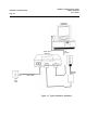
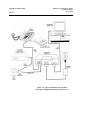
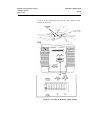
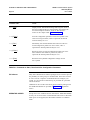
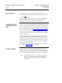
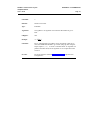
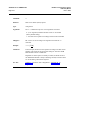
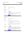
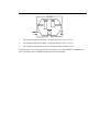
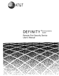
Figure 2-1 illustrates the needed hardware items for an arrangement
without a telephone, Figure 2-2 shows the set up for using a telephone
without adjunct equipment, and Figure 2-3 shows a similar setup with
some typical adjunct equipment.
DEFINITY Communications System
7400B Data Module
User’s Guide
CHAPTER 2: INSTALLATION
Page 2-2
PERSONAL
COMPUTER
7400B DATA
MODULE
EIA
CABLE
POWER
SUPPLY
D8W CORD
PBX
WALL
JACK
Figure 2-1. Typical Standalone Installation
DEFINITY Communications System
CHAPTER 2: INSTALLATION
7400B Data Module
Page 2-3
User’s Guide
Figure 2-2. Typical Installation with Telephone
CHAPTER 2: INSTALLATION
Page 2-4
DEFINITY Communications System
7400B Data Module
User’s Guide
Figure 2-3. Typical Installation with Telephone
and Adjunct Equipment Requiring Auxiliary Power
DEFINITY Communications System
CHAPTER 2: INSTALLATION
7400B Data Module
Page 2-5
User’s Guide
About the Terminal Device
The 7400B Data Module operates with any asynchronous data terminal
device that has an EIA-232-D (or RS-232-C) serial port connector. If
you are using a PC as your terminal, you will need a suitable data
communications software package.
Also, you must set the appropriate configuration options before
connecting the 7400B Data Module to a printer or plotter. To do this,
connect a data terminal or PC to Port 1 of the data module, change the
necessary configuration parameters, remove the data terminal or PC, and
then connect the printer of plotter. The configuration parameters used
for this type of operation are described in Chapter 4, "Operation and
Configuration," in a section titled “Remote Site Use.”
EIA-232-D cables and data communications software packages are
described in the following paragraphs.
Selecting an EIA-232-D
Cable
Select an EIA-232-D with a male connector at one end to mate with the
Port 1 connector of the 7400B Data Module, and a connector of the
appropriate "gender" at the other end to mate with the communications
port of your terminal device.
Note:
Cables with the earlier RS-232-C designation will also work.
The most common EIA-232-D cables are supplied with a male
connector at both ends. If you have this type of cable and the EIA-232D port on your terminal device is a male connector, you can use a cable
adapter commonly referred to as a “gender changer”. Otherwise, obtain
an EIA-232-D cable that has the appropriate gender connector at each
end to fit your application needs.
Selecting Data
Communications Software
The purpose of data communications software is to allow your PC to
operate as an asynchronous data communications terminal. Of the many
software packages available, all perform essentially the same functions,
but often in significantly different ways.
If you do not already have a communications software package, consult
with an experienced user for advice on selecting software to suit your
data communications needs. The following, though not required, are a
few helpful features that you may wish to look for in the software you
select:
●
●
Terminal mode. Also called local mode or chat mode, this
feature allows you to issue commands to the 7400B Data
Module. The software that you select must have some form of
terminal mode.
Dialing directory. This feature allows you to store several
frequently called numbers, often along with configuration of
the data options needed for completing the connection.
CHAPTER 2: INSTALLATION
DEFINITY Communications System
7400B Data Module
User’s Guide
Page 2-6
●
●
Predefine data options profiles. Some programs include
completely defined data option profiles (also called
configuration profiles) for popular modems. If available, select
the options profile for the Hayes® Smartmodem 2400™.
Command files. These files, also called script files, allow you
to define a group of commands that may be executed for
automatically logging into specific remote devices.
Appendix C, “Application Notes,” provides guidelines for using a few
of the more popular communications software packages with the 7400B
Data Module.
Selecting DCP Cords
The 7400B Data Module is supplied with a 5-foot D8W cord. Use this,
or obtain the appropriate length D8W telephone cord for DCP
connection between the 7400B Data Module and the PBX wall jack. If
you are using the with-telephone option, you will need a second D8W
telephone cord to connect between the data module and your telephone
or voice terminal.
Selecting DIP-Switch
Options
Three hardware options may be selected by setting switches on an
internal 8-position DIP switch (SW1). These options are described here,
and procedures for setting the switches are provided in a later section
titled “Setting the Hardware Option DIP Switches.”
With/Without Telephone Option (SW1-1)
When this option is set for operation without an associated telephone
(SW- 1 set to " WITHOUT PHONE"), the 7400B Data Module offers
only data service between a terminal device and a remote system.
Setting this option for operation with an associated voice terminal (SW1 is set to “WITH PHONE”) enables simultaneous data and voice
service over the same line from the PBX.
When the 7400B Data Module is optioned for “WITH PHONE,” an
AT&T 7400-series DCP digital voice terminal is connected to the data
module only for its voice service features; data service is provided
directly from the 7400B Data Module, and any data features that the
voice terminal may offer cannot be used.
Note:
A change in the setting of this option becomes effective
when the data module is powered on after being powered
off. The setting of this option cannot be changed
arbitrarily—it must agree with how the line is administered
at the PBX. For information on how to administer the
7400B Data Module at the PBX for use with or without a
telephone, refer to Appendix C, “Application Notes.”
CHAPTER 2: INSTALLATION
DEFINITY Communications System
7400B Data Module
Page 2-7
User’s Guide
Data Metering Option (SW1-5)
When the data metering option is disabled (SW1-5 set to "OFF"), the
transfer speed of the 7400B Data Module will adjust to match the
transfer speed of the remote system. The C0NNECT xxxx message
displayed when a connection is completed will always indicate the far
end speed.
When this option is enabled (SW1-5 set to "ON"), it allows the user to
set-up a call to a remote end device that is running at a lower speed than
the local data module. The CONNECT xxxx message will always
indicate the speed of the local data transfer. The data module performs
the speed conversion and uses the CTS lead to flow-control the user’s
terminal if it is sending too much data too fast. During the data transfer,
the DATA METERING LED indicates the state of the CTS lead.
Note:
If you are using a PC with a data communications package,
or a dedicated terminal that does not support CTS control,
you cannot make file transfers with the data metering option
enabled.
A change in the setting of this option becomes effective immediately
when the data module is in the idle mode or as soon as it is returned to
the idle mode. The data module is in idle mode any time that it is not in
test mode or connected to an active data call.
Make Busy on Local Loop Option (SW1-8)
This option controls the make-busy feature of the 7400B Data Module.
When the option is enabled (SW1-8 set to "ON"), the data module will
busyout the DCP line when either the Local Loopback or Local
Loopback/Self-Test mode is entered. The busyout condition is released
when the test ends.
Note:
HARDWARE
INSTALLATION
A change in the setting of this option becomes effective
immediately when the data module is in the idle mode or as
soon as it is returned to the idle mode. The data module is in
idle mode any time that it is not connected to an active data
call.
This section outlines procedures for setting the hardware options DIP
switches on the Data Module, connecting the EIA-232-D cable,
installing the power supply, and connecting the D8W telephone cord(s).
Caution:
To avoid possible shock hazards and damage to the
equipment, you should perform the installation steps in
the order given.
DEFINITY Communications System
CHAPTER 2: INSTALLATION
7400B Data Module
User’s Guide
Page 2-8
Setting the Hardware
Option DIP Switches
Three hardware options are selected by setting switches on an internal
8-position DIP switch. Setting these switches is described in the
following paragraph; however, for more information about using these
options, refer to Chapter 4, “Operation and Configuration.”
Note:
The factory-default settings of these switches are correct for
the vast majority of applications. Check the default settings
shown in Table 2-1 to determine whether you need to make
any changes.
Telephone
SW1-1
Without Phone
ON
With Phone
(factory-default)
OFF
Data Metering
SW1-5
On—enabled
ON
Off—disabled
(factory-default)
OFF
Busy Out on Local Loop
SW1-8
On—enabled
ON
Off—disabled
(factory-default)
OFF
TABLE 2-1 Option DIP Switch Settings
DEFINITY Communications System
CHAPTER 2: INSTALLATION
7400B Data Module
User’s Guide
Page 2-9
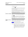
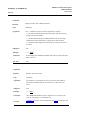
To access and set the hardware option switches, refer to Figure 2-4 and
perform the following:
Figure 2-4. Accessing the Hardware Option Switches
DEFINITY Communications System
7400B Data Module
User’s Guide
CHAPTER 2: INSTALLATION
Page 2-10
Caution:
1.
Connecting the EIA-232-D
Cable
Disconnect all cables and telephone cords attached at the
rear of the unit. Failure to disconnect all cables and
cords at this point could result in permanent damage to
the 7400B Data Module.
Remove the top access panel of the data module as follows:
a.
While applying a gentle lifting pressure at the rear edge of
the access panel, insert the tip of a ball-point pen or other
suitable device into each of the two tab-lock holes in the
rear panel to release the locking tabs.
b.
Lift and remove the access panel.
2.
If a ROM board is installed just inside the access opening of the
Data Module, grasp the edges of the ROM board inside the access
opening and lift the board out of its socket.
3.
Locate the 8-position DIP switch on the main circuit board,
approximately in the center of the area exposed by the access
opening.
4.
Set the appropriate positions of this DIP switch as shown in the
Table 2-1.
5.
If a ROM board was removed in step 2, reinsert the board into its
connector.
6.
Replace the access panel by placing it into position and pressing
down at the rear edge to engage the locking tabs.
Connect the EIA-232-D cable between the Data Module and the
terminal device as follows:
1.
Insert a male connector of the EIA-232-D cable into the connector
labeled PORT 1 on the rear panel of the Data Module. Tighten
both connector retaining screws.
2 .
Insert the other end of the EIA-232-D cable into the
communications port connector on the terminal device. Tighten
all retaining screws.
Note:
Be sure to attach any required adapter as discussed
previously in the paragraphs titled "Selecting the
EIA-232-D Cable."
DEFINITY Communications System
CHAPTER 2: INSTALLATION
7400B Data Module
User’s Guide
Connecting the DCP Cord
Page 2-11
Attach the DCP type D8W telephone cord as follows:
1.
Insert either end of the telephone cord into the connector on the
rear panel of the Data Module labeled LINE.
2.
Insert the other end of the telephone cord into the PBX wall jack.
3.
If you are using the with-phone option of the 7400B Data Module
(voice and data), install the second D8W telephone cord as
follows:
a.
Insert one end of the second D8W cord into the jack on your
7400-series DCP voice terminal.
b.
Insert the other end of the second D8W cord into the jack on
the rear panel of the Data Module labeled PHONE.
Note:
Connecting the Power
supply
An internal DIP-switch must be set correctly for
this option to work (see "Setting the Hardware
Option Switches" in this chapter). Also, if your
voice terminal has data capabilities, the data
features of the voice terminal are not supported
while it is connected to the 7400B Data Module.
Connect the separate power supply unit to the 7400B Data Module as
follows:
1.
Insert the output connector of the power supply into the connector
on the rear panel of the Data Module labeled “POWER.”
Caution:
2.
Be sure that the side of the power supply cable
connector labeled “TOP” is facing upward before
inserting the connector.
Insert the AC connector of the power supply unit into an
appropriate AC outlet.
Note:
Caution:
Since the 7400B Data Module does not have a power
on/off switch, the unit will power on as soon as the
power supply is connected to an active AC line.
Make certain that the AC outlet to which you connect the
power supply is unswitched (for example, not controlled
by a wall switch or light dimmer).
CHAPTER 2: INSTALLATION
DEFINITY Communications System
7400B Data Module
User’s Guide
Page 2-12
INITIAL SYSTEM CHECKS
This section describes procedures for initially checking out your
hardware and any required software. It is assumed at this point that your
hardware and data communications software have been properly
installed and are ready for use.
Note:
Power-Up Self-Test
Data communications software is required only if you are
using a PC as your terminal device. A dedicated data
terminal does not need data communications software.
When power is first applied to the 7400B Data Module, the unit
performs a self-test to determine that it is in working order. The
progression of the self-test is indicated by the sequential, left-to-right
lighting of the 10 front-panel LEDs.
If the self-test finds no problems, the LEDs labeled POWER/TEST and
TR will remain lit and all other LED lamps will go out.
Note:
The operation of the LEDs described here assumes that the
factory-default options are still in effect. Once certain
options have been changed, the operation of the LEDs may
differ from this description.
Your 7400B Data Module is now installed and ready for data
communications operation.
IF YOU ARE USING A PC
Review the documentation for your PC and data communications
software. Be sure that you understand both well enough to get the
software running and place your PC in terminal mode.
Since there is such a diversity of functionality among the many
packages available, refer to the user’s manual of the software package
for specific details of its use. Appendix C, “Application Notes”
provides guidelines for using a few of the more popular packages with
the 7400B Data Module.
IF YOU ARE USING A
DEDICATED TERMINAL
To determine whether your terminal is communicating with the 7400B
Data Module, type the following command line:
AT [ Enter ]
Note:
The two characters of the “AT” command prefix must be
typed as either both uppercase or both lowercase. That is,
you can type either at or AT, but At or aT will not
work.
If everything is operating properly, the command should appear on the
screen as you type it, and the 7400B Data Module should respond with
OK. Refer to Chapter 5,“Troubleshooting,” for help if you are not
getting these results.
CHAPTER 3: FIRST TIME USERS
DEFINITY Communications System
7400B Data Module
User’s Guide
Page 3-1
CHAPTER 3: FIRST TIME USERS
This chapter provides some basics on 7400B Data Module operation,
describes how to use a few AT commands that are essential for most data
communications operations, and then outlines a typical on-line session.
Note:
OPERATING MODES
The commands for the data module are referred to as AT
commands because you must type the letters “AT” as the
first characters on the line for most commands.
Except when the 7400B Data Module is in a test mode, it is always in
one of two distinct operating states or modes: command mode and online or data mode.
In command mode, the data module tries to interpret everything you
type on your keyboard as a command. In on-line mode, the data module
passes everything on as data.
While in on-line mode, typing a specific character three times in quick
succession (the factory-default escape sequence is 3 plus signs, or +++)
causes the data module to go into command mode without disconnecting
an active data call.
The operating modes, the escape sequence, and several AT commands
are explained further in Chapter 4, “Operation and Configuration.” All
AT commands are described fully in Appendix A, “AT Commands.”
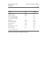
Character Formats
In this context, character format refers to the form a character may take
locally, between the 7400B Data Module and your terminal device. The
elements that make up character format are often referred to as
communication parameters. Formats supported by the 7400B Data
Module are shown in Table 3-1.
Data Bits
7
7
8
Parity
even or odd
mark or space
none
TABLE 3-1 CHARACTER FORMATS
Stop Bits
1
1
1
DEFINITY Communications System
CHAPTER 3: FIRST TIME USERS
7400B Data Module
User’s Guide
Page 3-2
All of these parameters may be changed on the local terminal device as
needed. The 7400B Data Module will adjust to match the speed and
parity of the local terminal device.
If you connect to a remote system and your screen shows a series of
nonsense characters (also referred to as "garbage"), chances are that you
need to adjust speed or parity.
For more information on configuration, see Chapter 4, “Operation and
Configuration.”
ESSENTIAL AT
COMMANDS
Note:
This section pertains mostly to dedicated terminals, since
many data communications packages for PCs may not allow
you to send AT commands directly to the data module.
This section provides a basic description of the most commonly used
AT commands. These few commands are all you will need for
completing many data communications tasks. In a later section titled
“Sample On-Line Session,” presented at the end of this chapter, you
will enter the commands manually from your terminal keyboard.
Note:
If you are using a PC with software that permits command or
script files, you may create files to perform automatic log in
for devices that you plan to communicate with frequently.
In this case, the commands used are typically not direct AT
commands, but function commands defined by the software
package. For more information on PC software, refer to
Appendix C, “Application Notes.”
Table 3-2 describes the subset of AT commands you will need for the
on-line session at the end of this chapter. For a complete description of
all AT commands, refer to Appendix A.
Note:
Except where otherwise noted, press [ Enter ] to complete all
AT command lines.
CHAPTER 3: FIRST TIME USERS
DEFINITY Communications System
7400B Data Module
Page 3-3
User’s Guide
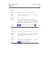
AT Command
AT
Description
The command prefix that must be typed as the first two letters of
all AT commands except +++ and A/. This prefix gets the
AT tention of the data module.
Note:
D
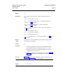
The Dial command. This command follows the AT and precedes
the number that you wish your data module to dial. For example:
atd71204 [ Enter ]
Note:
A/
The characters of the AT prefix must both be typed in
either uppercase or lowercase letters (AT or at will
work, but At or aT will not). Typing a space between
the AT prefix and the next command on the line is
optional, but do not separate the two letters “AT” with
a space.
Other commands may precede the D command, but
any characters following it will be interpreted as part
of the number that is to be dialed.
The redo or Again command. This is one of the two commands
that does not require the AT prefix. To repeat the previous
command line exactly, type A/ without pressing [ Enter ].
(more)
TABLE 3-2 AT Command Subset
DEFINITY Communications System
7400B Data Module
CHAPTER 3: FIRST TIME USERS
User’s Guide
Page 3-4
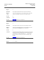
AT Command
+++
Description
The escape character sequence. This is one of the two
commands that does not require the AT prefix. Once
you have connected to the remote device, your data
module assumes the on-line mode of operation. If you
need to return to the command mode, leave the keyboard
idle for at least one second, and then type +++ without
pressing [ Enter ]. Within a few seconds, the data module
will respond with OK, signifying that it has entered the
command mode and is waiting for you to type a
command.
Whether OK is returned or not depends on the setting of
certain parameters. If the factory-default settings are in
effect, OK should be returned.
O
The return to On-line command. After using the +++
escape sequence to enter command mode, you can type
ato and press [ Enter ] to return to on-line mode.
Note:
This command will not work if you have
disconnected the data call.
H
The hang up or disconnect command. After using the
+++ escape sequence to enter command mode, you can
type ath and press [ Enter ] to disconnect the data call.
&F
The return to Factory-default settings command. If an
experimental change of your data module settings
produces unexpected results — and you are not sure how
to get out of the fix — type AT&F and press [ Enter ]. This
will return all configuration parameters back to the
factory-default settings.
TABLE 3-2 AT Command Subset (Contd.)
SAMPLE COMMAND LINES
This section presents a few sample AT command lines with
explanations of the results they will produce.
EXAMPLE 1: Dialing a number.
at d 5551212 [ Enter ]
CONNECT 2400
CHAPTER 3: FIRST TIME USERS
DEFINITY Communications System
7400B Data Module
User’s Guide
Page 3-5
In the first line of this example,
●
AT is the required command prefix,
●
D is the dial command,
●
and the remainder of the line is the telephone number.
Note:
The spaces between the commands and the telephone
number are included only for readability and are not
required. You may also insert hyphens (-) anywhere in the
telephone number for increased readability.
In the second line of this example, the data module returns a response
indicating that a connection with the remote end device has been
successfully completed at 2400 bps.
EXAMPLE 2: Dialing a telephone number outside your PBX domain with a
few other options thrown in.
at &f
BUSY
d
9-555-1212 [ Enter ]
In the first line of this example,
●
●
at is the required command prefix,
&f tells the data module to restore the factory-default configuration
parameters,
d is the dial command,
●
●
9 represents the access code required to dial a number outside your
PBX domain,
●
and the remainder of the line is the telephone number.
In the second line of this example, the data module indicates that it detected a
busy signal.
EXAMPLE 3: Using a time saver.
A/
The A/ command tells the data module to repeat the last command line
exactly. If, as in the previous example, you had issued the command to dial a
number and the data module returned the message BUSY, you could type the
A/ command to try the number again.
Note:
The A/ command must be the only command on the command
line, and you do not press [ Enter ] to complete the line.
DEFINITY Communications System
7400B Data Module
User’s Guide
CHAPTER 3: FIRST TIME USERS
Page 3-6
EXAMPLE 4: Changing data options.
at el &d2 s0=5 [ Enter ]
This command line is a command sequence that sets up the 7400B Data
Module to automatically answer incoming calls. The commands set the
following parameters:
●
●
●
●
AT is the required command prefix,
e1 causes characters entered from the keyboard to be echoed to the
screen while in command mode
&d2 causes the data module to hang up the call when the local
terminal turns off DTR
s0=5 causes the data module to enter automatic answer mode and
answer incoming calls on the fifth ring.
A SAMPLE ON-LINE
SESSION
This section outlines how to perform a simple on-line session using the
AT commands described in this chapter. For more information about all
AT commands, see Chapter 4, "Operation and Configuration" and
Appendix A, “AT Command Set.”
Starting the Session
The following is a sample data call to a fictitious bulletin board service.
If you know the number of a "real" bulletin board service, you might try
an actual log on by using that number and following the suggestions in
this session.
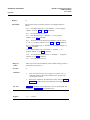
at d 9-555-7575 [ Enter ]
CONNECT 1200
The D command is used to dial the number of the bulletin board. Since
the connection was made successfully, the data module responded with
a message that says the remote end connected at 1200 bps.
The remote end may do nothing until you press a particular key a few
times, usually [ Enter ]. Typical of many data communications application
programs, this sometimes required input lets the remote end determine
whether you have connected with the correct communications
parameters in effect.
Possible Display Problems If the response from the remote end is unintelligible “garbage,” chances
are that the speed or parity bit selection is incorrect. In this case,
assuming that your terminal device allows, the parameters may be
corrected without disconnecting the call. Otherwise, you must
disconnect, correct the parameters, and then try the call again.
CHAPTER 3: FIRST TIME USERS
DEFINITY Communications System
7400B Data Module
Page 3-7
User’s Guide
Another possible problem is that the remote end response contains
normal words mixed in with strange characters, many of which are left
brackets ([). This usually indicates that the remote device is sending
ANSI display control sequences, and your terminal does not recognize
them (ANSI stands for American National Standards Institute).
On a PC, this can generally be remedied by first disconnecting the call,
editing the PC’s CONFIG.SYS file to include the line
DEVICE=ANSI.SYS
rebooting the PC, and then trying the call again. (For a log off
procedure, see the alternative method under “Disconnecting a Data
Call,” below.)
Note:
Disconnecting a Data Call
If the terminal device is not a PC, or the suggested remedy
does not seem to solve the problem, and then you will need
to consult the documentation for your dedicated terminal, or
for your PC and any software involved.
Most remote systems will have a command or menu selection for
logging off. When you select the appropriate means, the remote system
will usually disconnect or hang up. The PBX will disconnect from the
call and, after a moment, the data module will send the following
message to your display:
NO CARRIER
Alternatively, you can use the following log off procedure:
Selection: +++
OK
The prompt Selection: is simply a representation of how the remote
system might ask you for your next command or menu selection. Type
the escape sequence (default is +++) but do not press [ Enter ].
When the data module responds with OK, type the command line:
ath [ Enter ]
The PBX will disconnect from the remote end device, and the 7400B
will send the OK message to the terminal display.
DEFINITY Communications System
7400B Data Module
CHAPTER 4: OPERATION AND CONFIGURATION
Page 4-1
User’s Guide
CHAPTER 4: OPERATION AND CONFIGURATION
This chapter describes how to change, store, and recall configuration
parameters, outlines how to create and save custom configuration
profiles, and discusses more advanced command usage with example
command lines.
CONFIGURATION
PARAMETERS
Values for configuration parameters are selected by using AT
commands to change values contained in the S-registers. The Sregisters are a set of 8-bit memory locations that the data module
reserves for storage of configuration settings. For a description of AT
commands and S-registers used by the 7400B data module, refer to
Appendix A, “AT Command Set,” and Appendix B, “S-Registers.”
Parameter Storage and
Retrieval
Configuration parameter values include the option values selected by
AT commands that require option values, and the values stored in the
S-registers. A complete set of configuration parameter values is called a
profile. The 7400B Data Module has four configuration profiles at any
given time, one active, two stored, and one that permanently contains
the factory-default values.
Unsaved changes to configuration parameters remain in effect until they
are changed again, or until the data module is disconnected from the AC
power source. Before making or storing any changes, or to check
changes that you have made, you can issue an AT command to view the
values that are currently in the active profile and the two stored profiles.
The active profile contains the parameter values that are currently in
effect. All parameter values can be changed, and most changes can be
stored to one of the two profile storage locations by issuing an AT
command. Another AT command recalls values from one of the two
stored profiles into the active profile.
Factory-default parameter values are a selection of values that are
appropriate for a wide number of applications. These values are stored
permanently in ROM and you can issue an AT command to recall them
into the active profile at any time.
Commands to view, store, and recall configuration parameters are
summarized in Table 4-1. The commands discussed in this section are
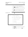
described in greater detail in Appendix A, “AT Command Set. ” To
determine whether a configuration parameter that affects a particular Sregister can be stored in memory, refer to Appendix B, “S- Registers.”
CHAPTER 4: OPERATION AND CONFIGURATION
DEFINITY Communications System
7400B Data Module
User’s Guide
Page 4-2
Command Line:
Action:
at&v [ Enter ]
Display current AT command settings and S-register values in
the active profile and the two stored profiles (also displays the
four stored telephone numbers, which are described in a
section of this chapter titled “Number Storage”).
at&w n [ Enter ]
Store the configuration parameters in the active profile to one
of the two storage locations, where n represents the desired
location and may be 0 or 1.
atz n [ Enter ]
Immediately reset the data module and recall one of the two
stored configuration profiles into active status, where n
represents the desired profile and may be 0 or 1.
at&y n [ Enter ]
Recall one of the two stored configuration profiles into active
status when the data module is powered on, where n
represents the desired profile and may be 0 or 1.
at&f [ Enter ]
Recall the factory-default configuration settings into the
active profile.
TABLE 4-1 Commands to Store, Recall and View Configuration Parameters
PC Software
Many data communications software packages for use with PCs provide
the possibility of writing script or command files. These files can then
be run to execute a sequence of commands that will configure your
system, or even provide an automatic log on procedure for a particular
remote end device.
Guidelines for use of some of the more popular software packages with
the 7400B Data Module are provided in Appendix C, “Application
Notes.”
OPERATING MODES
Except when a test condition has been initiated, the 7400B Data Module
is always in one of two states: command mode and on-line or data mode.
When power is first applied, the data module initializes to command
mode.
DEFINITY Communications System
CHAPTER 4: OPERATION AND CONFIGURATION
7400B Data Module
User’s Guide
Page 4-3
In command mode, the 7400B Data Module looks at everything you
type on your keyboard. When you type in something that the data
module recognizes as a valid command with a valid parameter (if
required), it will execute the action requested. A valid command with
an invalid parameter will produce the ERROR result code, and an invalid
command is simply ignored.
In on-line mode, everything you type is passed as data without
interpretation by the 7400B Data Module, except the escape sequence.
The escape sequence, described in later paragraphs, provides a way of
switching the data module back to command mode without
disconnecting a data call.
ISSUING COMMANDS
The following paragraphs describe the elements of a command line and
how the 7400B Data Module responds to a command line when it is
issued.
Command Line Prefix
All commands issued to the 7400B Data Module, except the escape
sequence and the repeat command, must begin with the letters “AT”.
This is called the command line prefix and must be entered as either
both uppercase or both lowercase letters (that is, at and AT will work,
but aT or At will not).
The AT prefix (also known as the ATtention command) alerts the data
module to expect one or more commands to follow. Each time the AT
prefix is sent, the data module adjusts its speed and parity to match your
local terminal.
Command Buffer
As you type in a command, each character is saved in a 40-character
buffer. The AT prefix, spaces, and the [ Enter ] at the end of the command
line are not saved and do not add to the character count. If you try to
type more than 40 countable characters on one line, the result code
ERROR will be displayed on your terminal screen, and the command
line will be ignored.
Command Line Set Up
A command line begins with the AT prefix, includes one or more
commands, and finishes with a line termination, usually issued by
pressing the [ Enter ] key. The factory-default line termination character
is an ASCII carriage return, represented by the decimal number 013
stored in S-register S03.
DEFINITY Communications System
CHAPTER 4: OPERATION AND CONFIGURATION
7400B Data Module
User’s Guide
Page 4-4
Note:
A special application may require choosing a different line
terminating character, accomplished by issuing the
command:
ats3= ddd [ Enter ]
where ddd is a 1- to 3-digit decimal representation of the
ASCII character with a range of 0 through 127 (see ASCII
Character Set in Appendix D).
Caution:
Before changing this or any other default ASCII
character, make certain that your terminal device will
recognize the new character.
If you make an error while typing a command line, you can send the
backspace character, usually issued by pressing the [ Backspace ] key, as
often as needed to delete the error. However, as soon as you enter the
AT prefix, the data module immediately reads it and sets up for a
command to follow. Hence, you cannot delete the AT prefix once it is
typed.
The factory-default backspace character is an ASCII backspace,
represented by the decimal number 008 which is stored in S-register
S05.
Note:
A special application may require choosing a different
backspace character, accomplished by issuing the command:
ats5=ddd [ Enter ]
where ddd is a 1- to 3-digit decimal representation of the
ASCII character with a range of 0 through 127 (see ASCII
Character Set in Appendix D).
Caution:
Before changing this or any other default ASCII
character, make certain that your terminal device will
recognize the new character.
Once you complete a command line by pressing [ Enter ], the data module
will try to interpret all characters on the command line as valid
commands. If the data module finds a character that is not a valid
command, it will ignore the erroneous character and any remaining
characters on the command line; if it finds an incorrect parameter for a
valid command, the data module will issue the ERROR result code and
ignore any remaining characters.
CHAPTER 4: OPERATION AND CONFIGURATION
DEFINITY Communications System
7400B Data Module
Page 4-5
User’s Guide
Command
Acknowledgement
Most commands are acted upon immediately and are acknowledged by
the result code OK. This assumes that the result codes are configured in
the verbose form (command V1 is in effect), and are enabled (Q0 in
effect). Other options are the short or numeric form result code is set
(V0), which would produce a 0 (zero) instead of the message OK, and no
visible acknowledgement (Q1). Refer to Appendix A, “AT Command
Set” for descriptions of the V and Q commands.
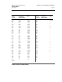
Several other result codes may appear on your terminal screen while the
data module is completing a call. The option selected by the X
command controls which of these result codes may appear on the screen
of your terminal (the X command is described in Appendix A). All
result codes that may be returned by the 7400B Data Module are shown
in Table 4-2 and in Appendix D, “Quick-Reference Summaries.”
Verbose Form
Numeric
Description
OK
0
Command accepted
CONNECT
1
Connection made at 300 bps
Note:
If command X1 is in effect, CONNECT
means connection made at whatever
speed both ends of the call agreed upon.
RING
2
Ring signal detected
NO CARRIER
3
Carrier signal not detected or lost
ERROR
4
Error in command line
CONNECT 1200
5
Connection made at 1200 bps
NO DIALTONE
6
No dial tone detected
BUSY
7
Busy signal detected
CONNECT 2400
10
Connection made at 2400 bps
CONNECT 4800
11
Connection made at 4800 bps
CONNECT 9600
12
Connection made at 9600 bps
CONNECT 19200
14
Connection made at 19200 bps
TABLE 4-2 Result Codes
CHAPTER 4: OPERATION AND CONFIGURATION
DEFINITY Communications System
7400B Data Module
User’s Guide
Page 4-6
Multiple Characters
If you type in the at prefix and it displays on your screen as aatt,
you may disable the command echo by typing the following command:
ate0 [ Enter ]
The command will appear as aattee00 as you type it, but the data
module will send the response code OK to your screen. The next
command that you type should appear in single characters.
FROM DATA MODE TO
COMMAND MODE AND
BACK
A special escape sequence can be typed at any time during a data call to
return temporarily to command mode. Your call does not disconnect, but
data is not exchanged. Once you have “escaped” to command mode,
the data module returns OK to acknowledge that it has entered command
mode (see previous section titled "Command Acknowledgement").
At this point, you can issue commands to the data module. As long as
the data call has not been disconnected, you can use the O command to
return to on-line mode.
One other condition will cause the data module to switch from data
mode to command mode. If the PBX senses that the remote device has
disconnected, it will disconnect the call to the data module. The data
module will turn off the CD, OH, and DATA LEDs (see note), display a
result code message on your terminal screen (such as NO CARRIER),
and then return to command mode.
The escape sequence and all other commands discussed in this section
are explained in Appendix A, “AT Commands.”
DIALING A NUMBER
The dial command is issued to the 7400B Data Module in the form
atd nnn...n, where nnn...n represents the number you wish to dial. The
command line can hold up to 40 characters, so you can usually precede
the D command with other commands on the same line, if you wish.
Note:
Every character following the D command is regarded as
part of the number to be dialed and is sent to the PBX;
hence, the D command must be the last command in the
command line.
CHAPTER 4: OPERATION AND CONFIGURATION
DEFINITY Communications System
7400B Data Module
Page 4-7
User’s Guide
The following is an example:
atd74768 [ Enter ]
In the example, the command will cause the data module to go off hook,
dial the number, and then wait the period of time specified in S-register
S7 for the call to be completed.
If the call is not completed, the data module will disconnect and send
the result code NO CARRIER to your display screen. When a call is
successfully completed, the data module will send the result code
CONNECT nnnn to your screen, where nnnn represents the speed of
the 7400B Data Module, (for example, 1200).
REPEATING A COMMAND
As mentioned earlier, the command buffer contains the last completed
command line. If you wish to repeat the previous command line without
retyping it, type A/ without the AT command prefix and without
pressing [ Enter ].
This command is most useful when you have typed a command line to
have the 7400B Data Module dial a number, and the data module returns
the result code BUSY. Use the A/ command to redial the number as
often as you wish.
STORING A TELEPHONE
NUMBER
The 7400B Data Module is capable of storing up to four telephone
numbers, each of which can contain up to 25 characters. Numbers
stored in this way remain available indefinitely, even after the data
module has been powered off and then on again.
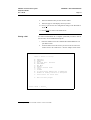
Table 4-3 describes the command lines used to store a telephone
number, delete a number from storage, and dial a stored number.
Note:
Digits 0 through 9 and all letters “a” through “z” and “A”
through “Z” may be part of the stored “number.” Spaces
and hyphens (-) may be used in the number when typing the
command line. Spaces are not stored and do not add to the
total count of characters in the stored number, but all other
ASCII characters are stored and counted. Any ASCII
character may be used, as long as it is acceptable to the
PBX.
CHAPTER 4: OPERATION AND CONFIGURATION
DEFINITY Communications System
7400B Data Module
User’s Guide
Page 4-8
Command line:
Action:
at&z m=nnn...n [ Enter ]
Store number nnn...n in location m, which is one of four
locations designated by the numbers 0 through 3. For
example:
at&z2=92015551212 [ Enter ]
stores the number 92015551212 in number storage location 2.
at&zm= [ Enter ]
Delete any number stored in location m, which is one of four
locations designated by the numbers 0 through 3. For
example:
at&z2= [ Enter ]
deletes any number that may have been stored in number
storage location 2.
atds=m [ Enter ]
Dial the number stored in location m, which is one of four
locations designated by the numbers 0 through 3. For
example:
atds=2 [ Enter ]
causes the data module to send whatever is contained in
number storage location 2 to the PBX as a number to be
dialed.
TABLE 4-3 Commands for Using Stored Telephone Numbers
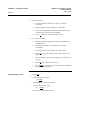
AUTOMATIC ANSWERING
The 7400B Data Module can be set up to answer incoming data calls
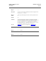
automatically. To initialize this option, type the command line:
ats0=nnn [ Enter ]
where nnn is a decimal number in the range of 1 through 255,
representing the number of rings to wait before answering.
DEFINITY Communications System
CHAPTER 4: OPERATION AND CONFIGURATION
7400B Data Module
User’s Guide
Page 4-9
If nnn is 0 (the factory-default setting), the automatic answer feature is
turned off. The red LED on the front of the data module labeled “AA”
lights when the automatic feature is turned on.
REMOTE SITE USE
The 7400B Data Module can be used at a remote site as a dedicated
service device to answer incoming data calls, send data to a remote end
device, and then hang up. For example, you may wish to provide access
to a printer from a remote site.
The following is a typical command line you might use for setting up
this operation (spaces are used here for readability, but are not required):
at &c1 &d2 q1 s0=1 &w0 &y0
[ Enter ]
Following the at prefix, the commands in the example produce the
following results:
●
&C1 sets the Data Carrier Detect (DCD) circuit of the data module
to operate according to the EIA standard.
●
&D2 sets the data module to go on hook when an on-to-off transition
is detected on the Data Terminal Ready (DTR) input, disconnecting
the call
●
Q1 turns off the result codes that would be the normal responses of
the data module to commands that it receives.
●
S0=1 turns on the automatic answer feature and causes the data
module to answer an incoming data call on the first ring.
●
●
&W0 causes the current configuration to be stored in data profile
storage location 0.
&Y0 selects the configuration stored in data profile storage location
0 to become the current configuration each time the data module is
powered on
Refer to Appendix A, “AT Command Set,” for a complete description
of each command used in this section.
RESET AND
CONFIGURATION RECALL
Two commands are available for recovering from various data
communications problems. You can reset the 7400B Data Module and
recall one of two stored data profiles as the current configuration. The
form for this command is as follows:
atz n [ Enter ]
where n is the number 0 or 1, representing the data profile to be recalled.
CHAPTER 4: OPERATION AND CONFIGURATION
DEFINITY Communications System
7400B Data Module
User’s Guide
Page 4-10
A second command allows you to recall the factory-default
configuration if, for instance, you loose track of changes you have made
and need to start over. The form for this command is as follows:
at&f [ Enter ]
CHAPTER 5: TROUBLESHOOTING
DEFINITY Communications System
7400B Data Module
Page 5-1
User’s Guide
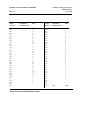
CHAPTER 5: TROUBLESHOOTING
This chapter describes procedures for troubleshooting most problems
that may be encountered while installing, configuring, and operating the
7400B Data Module.
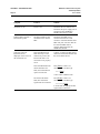
HOW TO USE THIS
CHAPTER
Use the following guidelines to isolate and correct a problem:
1.
Scan through the “Symptom” column in the chart to find the
description that best describes the problem situation you have
encountered.
2.
In the “Problem” column, one or more problem descriptions is
offered. Select the one that best describes the observable
condition, or try each suggestion in turn until the trouble has been
corrected.
3.
Perform the task described in the “Solution” column. In cases
where you are directed to type an AT command to correct the
problem and the 7400B Data Module is in the command mode,
simply type the command; from data mode, do the following:
4.
a.
Type the escape sequence (+++) to enter command mode;
the data module will respond with OK or 0 (unless the Q1
option has been set to disable result codes).
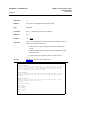
b.
Type the suggested command line (if the solution suggests
disconnecting the call, type the command line ath [ Enter ]).
To return to data mode after using the escape sequence to enter
command mode, type the command line ato [ Enter ].
DEFINITY Communications System
CHAPTER 5: TROUBLESHOOTING
7400B Data Module
User’s Guide
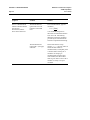
Page 5-2
Symptom
Problem
Solution
All LEDs are off.
Power is off.
Check that the AC outlet is live.
Check that the power supply unit is
connected to the 7400B Data
Module and to the AC outlet.
POWER/TEST and DATA
LEDs flash together.
The data module has lost
communications with the
PBX.
Check that the D8W cord is
connected between the LINE
connector of the data module and a
PBX wall jack. Note also that the
line from the PBX must be
properly administered for the
7400B Data Module.
Characters typed on
keyboard are not
displayed on the screen of
the terminal device.
If the SD LED does not
flash when keys on the
terminal are pressed, the
EIA-232-D cable is not
connected or not properly
wired.
Connect or replace the EIA-232-D
cable between the data module and
the local terminal device.
If the SD LED flashes but
the RD LED does not
flash, the command echo
option is turned off.
Press [ Enter ] to start a new
command line, and then type
atel [ Enter ]
to turn on the command echo.
The SD and RD LEDs
flash, but certain EIA
signal leads are turned off.
Press [ Enter ] to start a new
command line, and then type
at&s0&c0 [ Enter ]
to ensure that the appropriate EIA
signal leads are turned on.
CHAPTER 5: TROUBLESHOOTING
DEFINITY Communications System
7400B Data Module
Page 5-3
User’s Guide
Symptom
Problem
Solution
Call disconnects
immediately after an
attempt to connect; NO
CARRIER may be
displayed on the local
terminal device; CHECK
SPEED LED lights.
The speed of the far end
device is higher than the
speed of the local terminal
device.
Change the speed of the local
terminal device to match that of the
far end device. If the speed of the
far end device is not known, set the
local terminal device to the highest
speed available.
The far end device is set
up for half-duplex or
synchronous operation.
The 7400B Data Module cannot
communicate with a far end device
that is operating half-duplex or
synchronous. This problem can be
resolved only if the far end device
can be reconfigured for fullduplex, asynchronous operation.
The far end device is busy
with another call.
Try the call again.
The telephone number
was dialed incorrectly.
Check the number of the far end
device that you wish to call and try
the call again.
The far end device is not
busy, but the PBX has
restricted access to the
called device.
This situation can only be resolved
by having the PBX readministered
to remove the access restriction.
Call disconnects
immediately after an
attempt to connect; BUSY
may be displayed on the
local terminal device;
CHECK SPEED LED
does not light.
CHAPTER 5: TROUBLESHOOTING
DEFINITY Communications System
7400B Data Module
User’s Guide
Page 5-4
Symptom
Problem
Solution
The PC communications
software indicates that the
call has been
disconnected, but the
DATA LED remains lit.
The data module has
ignored the on-to-off
transition of the DTR
lead.
From command mode, type the
command
at&d2 [ Enter ]
to set the DTR lead option to
disconnect on DTR lead transition
from on-to-off. Alternatively,
determine and use the command
provided by the communications
software to implement this change.
The data module has
ignored the H (hang-up)
command.
Ensure that after the escape
sequence (+++) has been entered to
switch the data module to
command mode, an adequate pause
is allowed before issuing the H
command. In escaping to
command mode with the result
codes enabled, the data module
must be given time to return OK or
0 before it is ready to accept a
command.
CHAPTER 5: TROUBLESHOOTING
DEFINITY Communications System
7400B Data Module
Page 5-5
User’s Guide
Symptom
Problem
Solution
The AA LED flashes but
the data module does not
automatically answer the
incoming call.
The automatic answer
option is not enabled;
when there is no incoming
call, the AA LED is off.
From the command mode, type
The automatic answer
option is enabled; the AA
LED is on when there is
no incoming call, but the
terminal device is not
ready (TR LED is off).
If the local terminal is a PC,
configure the communications
software to turn on the DTR lead,
or set the data module to ignore the
DTR lead by typing
The automatic answer
option is enabled; the AA
and TR LEDs are lit, but
the POWER/TEST lamp is
flashing, indicating that
the data module is in a
local loopback test mode.
Terminate the local loopback test
by typing
ats0=1 [ Enter ]
to turn on the automatic answer
feature. Set the value following
the equal sign (1 in the example) to
the ring number on which you want
the data module to answer an
incoming call. The automatic
answer feature is turned off by
setting this value to 0.
at&d0 [ Enter ]
at&t0 [ Enter ]
DEFINITY Communications System
7400B Data Module
User’s Guide
CHAPTER 5: TROUBLESHOOTING
Page 5-6
Symptom
Problem
Solution
Transmitted and/or
received data contains
errors.
Speed settings of the
terminal device and the
data module are not the
same.
Change terminal device speed to
agree with the speed that was
indicated in the C0NNECT nnnn
message.
The local terminal device
and the far end device are
configured for different
parity settings.
Change the parity setting of the
local terminal device to match that
of the far end device.
Far end data errors only
during file transfer with
PC data communication
software.
Disconnect the call, set the data
metering option to off (see
“Setting the Hardware Option DIP
Switches” in Chapter 2), reestablish the call, and try the file
transfer again.
The display result codes
option is turned off.
Turn on the display result codes
option by typing
The DATA LED is lit, but
a CONNECT xxxx
message or numeric result
code was not displayed.
Numeric code returned
when CONNECT xxxx
message is preferred.
atq0 o [ Enter ]
The O command at the end of the
above command line will cause the
data module to return to the on-line
mode and send the CONNECT xxxx
message, or an equivalent numeric
code, to the terminal display (see
“Result Codes” in Appendix D).
The result code format
option is set to numeric
form.
Change the result code format
option to message form by typing
atv1 [ Enter ]
DEFINITY Communications System
CHAPTER 5: TROUBLESHOOTING
7400B Data Module
Page 5-7
User’s Guide
Symptom
Problem
Solution
Commands are displayed
without error as they are
typed (echoed), but the
data module does not
respond to any command.
The local terminal device
is set to a speed not
supported by the 7400B
Data Module.
Set the terminal device for one of
the supported speeds: 300, 1200,
2400, 4800, 9600, or 19200 bps.
The CONNECT message
is sent without a speed
indication, but the far end
device is not set at 300
bps.
The data module is
configured to display only
the basic set of result
codes (option x0).
Configure the data module to send
CONNECT nnnn messages for all
speeds except 300 bps by typing
The terminal device has
its DTR lead turned on,
but the TR LED is off.
A defective or nonstandard (null-modem)
EIA-232-D cable is in use.
Replace the EIA-232-D cable with
one that is wired correctly.
atx4 [ Enter ]
APPENDIX A: AT COMMAND SET
DEFINITY Communications System
7400B Data Module
Page A-1
User’s Guide
APPENDIX A: AT COMMAND SET
This appendix contains an explanation of each AT command accepted
by the 7400B Data Module. Labels used in the descriptions are defined
as follows:
Label
Description
Command:
The command is shown as it should be typed. The command may be typed in
uppercase or lowercase. Spaces may be typed between multiple commands on
the same command line for readability, but the spaces are ignored by the 7400B
Data Module.
Function:
A brief, functional description of the command is provided here.
Type:
Type may be immediate or configuration. An immediate command causes the
data module to perform an action as soon as the command is sent (for example,
go off-hook or dial a number). A configuration command modifies a
configuration parameter during the current session.
Arguments:
Many commands accept or require a numerical argument. Whether an
argument is required and the range of acceptable values for the argument is
shown here.
S-Register:
The S-registers consist of 28 1-byte memory locations in the data module,
designated as S0 through S27. The S-registers hold values for defining the
current configuration of the data module. Some commands modify a specific
S-register, and some commands perform an action based on the current value
stored in an S-register. Whether an S-register is modified or read by the current
command is explained here.
(more)
APPENDIX A: AT COMMAND SET
Page A-2
Label
DEFINITY Communications System
7400B Data Module
User’s Guide
Description
(Contd.)
Example:
A sample command line follows this label to demonstrate how the command
may be used.
Comments:
An explanation of the example and any other information about the command
not provided elsewhere is provided here. Additional commands may be typed
on the same command line with the command currently under discussion, unless
noted otherwise.
See Also:
Following this label are suggestions on where to look for more information
about the current command and a listing of any other commands that may be
used with or affect the use of the current command.
DEFINITY Communications System
APPENDIX A: AT COMMAND SET
7400B Data Module
Page A-3
User’s Guide
Command:
+++
Function:
Escape sequence.
Type:
immediate
Arguments:
none
S-Register:
none
Example:
+++
Comments:
The purpose of the +++ command is to provide a way to switch the
data module from on-line or data mode to command mode without
disconnecting a data call that is in progress. As long as the call is not
disconnected, you can return to the on-line mode with the O
command.
This is one of the two commands that does not require the AT prefix
(A/ is the other one), and it is never followed by pressing [ Enter ]. The
value in S12 determines how long your keyboard should remain idle
before entering the escape sequence, as well as the maximum
allowable time between entering each character of the sequence. The
character used in the escape sequence is determined by the value in S2
(default is ASCII 43, the plus sign).
See Also:
Chapter 3, “First Time Users,” Chapter 4, "Operation and
Configuration"; the O command in this appendix; S2 and S12 in
Appendix B.
APPENDIX A: AT COMMAND SET
DEFINITY Communications System
7400B Data Module
User's Guide
Page A-4
Command:
A
Function:
Go off-hook in Answer mode.
Type:
immediate
Arguments:
none
S-Register:
Bit 7 of S14 is set to 0.
Example:
ata [ Enter ]
Comments:
The A command causes the data module to go off-hook in answer
mode and attempt to answer an incoming call. The option set by the
&D command and the contents of S0 and S1 are ignored when this
command is issued.
See Also:
Command &D; Chapter 3, “First Time Users,” Chapter 4, “Operation
and Configuration”; Appendix B, “S- Registers.”
Command:
A/
Function:
Re-execute the last valid command line.
Type:
immediate
Arguments:
none
S-Register:
none
Example:
a/
Comments:
This is one of the two commands that does not require the AT prefix
(+++ is the other one). To repeat the previously executed command
line exactly, type A/ without pressing the Return or Enter key. This
command must be typed at the beginning of a new line and cannot be
combined with any other command.
See Also:
Chapter 3, "First Time Users."
APPENDIX A: AT COMMAND SET
DEFINITY Communications System
7400B Data Module
Page A-5
User’s Guide
Command:
D
Function:
Dial a telephone number.
Type:
immediate
Arguments:
The D command requires an ASCII character string, which is sent by
the data module to the PBX. The string may include any ASCII
character, with the following restrictions:
●
If the letters “t” or “p” (uppercase or lowercase) are typed as the
first character following the D command, the data module will
delete either character.
For example, if you want your dial string to be the mnemonic
“TEXAS,” you must type the “T” twice (the first “t” may be
uppercase or lowercase), producing the command line:
atdtTEXAS [ Enter ]
The “t” following the D command will be discarded and the
string “TEXAS” will be sent to the PBX as a dial mnemonic (the
PBX must be administered to recognize this mnemonic as the
representation of a number to be dialed).
●
●
The PBX may interpret certain non-alphanumeric characters as
commands and perform an unexpected action, if you did not
intend to send the command to the PBX. Consult the
documentation for your PBX to determine which characters may
be interpreted as commands.
The string (or AT command) s =n, where n may be a number
from 0 through 3, will cause the data module to send the
contents of its respective telephone number storage location to
the PBX as the telephone number. For details on how to use this
feature, refer to “Storing a Telephone Number” in Chapter 4,
“Operation and Configuration.”
(more)
APPENDIX A: AT COMMAND SET
DEFINITY Communications System
7400B Data Module
Page A-6
User’s Guide
Command:
D (Contd.)
S-Register:
Bit 7 of S14 is set to 1.
Example 1:
atd555–1212 [ Enter ]
Example 2:
atds=1 [ Enter ]
Comments:
In example 1, the number 555-1212 is dialed. The hyphen (-) is
optional and may be used for easier reading of the command line. In
example 2, the number stored in telephone number location 1 is dialed.
The maximum length of the ASCII string is 39 characters; the AT
prefix, the carriage return, and spaces used for readability do not add to
the character count for the line.
Note:
Other commands should not be issued following the dial
string until the call is either completed or fails. If anything
is typed before the call is completed, the call will fail.
See Also:
Chapter 3, "First Time Users," Chapter 4, "Operation and
Configuration."
Command:
E
Function:
Turn the command echo on or off.
Type:
configuration
Arguments:
No argument or an argument of 0 disables echo and an argument of 1
enables echo. The factory-default is 1.
S-Register:
Bit 1 of S14 is set according to the argument of the command.
Example:
ate1 [ Enter ]
Comments:
Typically, for a display terminal operating in full-duplex mode, use the
1 argument if you wish to see the AT commands on the screen as you
type them. If your display terminal is operating in half-duplex mode,
use the 0 argument (the 1 argument would cause characters typed to
appear on the screen like tthhiiss).
See Also:
Chapter 4, “Operation and Configuration.”
DEFINITY Communications System
7400B Data Module
APPENDIX A: AT COMMAND SET
Page A-7
User’s Guide
Command:
H
Function:
Switch hook control.
Type:
immediate
Arguments:
No argument or an argument of 0 causes the data module to go onhook.
S-Register:
none
Example:
ath [ Enter ]
Comments:
The H command with no argument can be used during a data call to
cause the 7400B Data Module to go on-hook (hang up) after using the
escape sequence (+++) to return to command mode. An argument of 0
produces the same result, and an argument of 1 is accepted but causes
no action.
See Also:
The escape sequence command (+++); Chapter 4, “Operation and
Configuration.”
APPENDIX A: AT COMMAND SET
DEFINITY Communications System
7400B Data Module
User’s Guide
Page A-8
Command:
I
Function:
Request product code or ROM checksum.
Type:
immediate
Arguments:
The I command accepts one of three arguments as follows:
0 - The data module displays the decimal number 249, followed by a
carriage return and line feed.
1 - The data module displays the ROM checksum as two four-digit
hexadecimal values, followed by a carriage return and line feed.
2 - The data module displays OK, followed by a carriage return and
line feed.
S-Register:
none
Example:
ati0 [ Enter ]
Comments:
In the example, the 7400B Data Module will return its product ID code
as the value 249.
See Also:
none
Command:
O
Function:
Return to the on-line mode.
Type:
immediate
Arguments:
No argument or an argument of 0 (zero) causes the data module to
return from command mode to on-line mode, if a data call is still
active.
S-Register:
none
Example:
ato [ Enter ]
Comments:
The 7400B Data Module accepts an argument of 1 but treats it the
same as no argument or an argument of 0.
See Also:
Chapter 4, “Operation and Configuration”; the +++ command in this
appendix.
DEFINITY Communications System
APPENDIX A: AT COMMAND SET
7400B Data Module
User's Guide
Page A-9
Command:
Q
Function:
Turn the display of result codes on or off.
Type:
configuration
Arguments:
No argument or an argument of 0 enables the display of result codes;
an argument of 1 disables the display of result codes. The factorydefault is result codes enabled.
S-Register:
Bit 2 of S14 is set according to the argument used with the Q
command.
Example:
atq1 [ Enter ]
Comments:
In the example, the result codes are disabled. Use this option only if
you wish to prevent the data module from returning result codes after
an AT command is issued.
See Also:
Chapter 4, “Operation and Configuration;” result codes in either
Chapter 4 or Appendix D, “Summary Tables;” the V and X
commands in this appendix.
Command:
V
Function:
Select format for result codes.
Type:
configuration
Arguments:
No argument or an argument of 0 causes the data module to return the
short form or numeric result codes; an argument of 1 causes the data
module to return the verbose form or text message result codes. The
factory-default setting is the verbose form.
S-Register:
Bit 3 of S14 is set according to the argument used with the V
command.
Example:
atv [ Enter ]
Comments:
The example would set the short form or numeric result code format.
See Also:
Chapter 4, “Operation and Configuration”; result codes in either
Chapter 4 or Appendix D, “Summary Tables;” the Q and X
commands in this appendix.
APPENDIX A: AT COMMAND SET
DEFINITY Communications System
7400B Data Module
Page A-10
User’s Guide
Command:
X
Function:
Control the extended result code set and dialing capabilities.
Type:
configuration
Arguments:
The X command accepts one of 5 arguments as follows:
0 - The basic result code set (0—4) is enabled. No dial tone or busy
signal detection. No speed indication on connect.
1 - Result codes 0—5, 10—12, and 14 are enabled. No dial tone or
busy signal detection. Speed indication on connect.
2 - Result codes 0—6, 10—12, and 14 are enabled. Wait for dial tone
before dialing. Call is aborted if dial tone is not detected within
length of time in S7. No busy signal detection. Speed indication on
connect.
3 - Result codes 0—5, 7, 10—12, and 14 are enabled. No dial tone
detection. Busy signal detection enabled. Speed indication on
connect.
4 - Result codes 0 - 7, 10 - 12, and 14 are enabled. Blind dialing
capability is disabled. Speed indication is provided when a
connection is established. Busy signal detection and dial tone
detection are enabled (see comments). This is the factory-default
setting.
S-Register:
Bits 4, 5, and 6 of S22 are set according to the argument given with the
X command.
Example:
atx2 [ Enter ]
Comments:
In the example, the results described under argument value 2 are
implemented. Regardless of which argument is used, the data module
will wait until the call is completed, or the time set in register S7
expires. All arguments do change the appropriate bits in S22 and
affect the result codes returned.
See Also:
Chapter 4, “Operation and Configuration”; result codes in either
Chapter 4 or Appendix D, “Summary Tables;” the Q and V
commands in this appendix.
DEFINITY Communications System
APPENDIX A: AT COMMAND SET
7400B Data Module
Page A-11
User’s Guide
Command:
Z
Function:
Reset and recall a stored profile.
Type:
immediate
Arguments:
No argument or an argument of 0 recalls the configuration profile
stored in location 0; an argument of 1 recalls the configuration profile
stored in location 1.
S-Register:
none
Example:
atz1 [ Enter ]
Comments:
In the example, the z command causes the 7400B Data Module to
reset, and then loads the configuration profile stored in location 1 into
the active location.
See Also:
Chapter 4, “Operation and Configuration.”
APPENDIX A: AT COMMAND SET
DEFINITY Communications System
7400B Data Module
User’s Guide
Page A-12
Command:
&C
Function:
Data Carrier Detect (DCD) options.
Type:
configuration
Arguments:
The &C command accepts one of two arguments as follows:
0 - (or no argument) maintain the DCD circuit on at all times
(factory-default setting)
1 - the DCD circuit operates according to the EIA-232-D standard
S-Register:
Bit 5 of S21 is set according to the argument used with the &C
command.
Example:
at&c1 [ Enter ]
Comments:
In the example, the DCD circuit operates according to the EIA-232-D
standard. This would be an appropriate setting for when the 7400B
Data Module is used at a remote site.
Regardless of which option is currently in effect, the DCD circuit of
the 7400B Data Module is always off during self-test, and turns off for
0.5 second during a disconnect sequence.
See Also:
Chapter 4, “Operation and Configuration”; Appendix B, “SRegisters.”
DEFINITY Communications System
APPENDIX A: AT COMMAND SET
7400B Data Module
User’s Guide
Page A-13
Command:
&D
Function:
Data Terminal Ready (DTR) options.
Type:
configuration
Arguments:
The &D command accepts one of four arguments as follows:
0 - ignore the DTR interchange circuit (factory-default setting).
1 - return to the command state if an on-to-off transition is detected
on the DTR input; an active data call is not disconnected.
2 - go on hook when an on-to-off transition is detected on the DTR
input (EIA-232-D standard); an active data call is disconnected.
3 - perform a reset if an on-to-off transition is detected on the DTR
input; an active data call is disconnected.
S-Register:
Bits 3 and 4 of S21 are set according to the option used with the &D
command.
Example:
at&d2 [ Enter ]
Comments:
In the example, the DTR circuit is set according to the EIA-232-D
standard. This would be an appropriate setting for when the 7400B
Data Module is used at a remote site as a dedicated device to
automatically answer an incoming data call.
For the 0 option, the front panel DTR indicator (TR LED) is always on,
regardless of the state of the DTR input; for all other options the
indicator follows the state of the DTR input.
If the change of state for the DTR circuit persists for a time shorter
than specified in S25, the change is ignored.
See Also:
Chapter 4, “Operation and Configuration”, Appendix B, “SRegisters.”
APPENDIX A: AT COMMAND SET
DEFINITY Communications System
7400B Data Module
User’s Guide
Page A-14
Command:
&F
Function:
Load the factory-default configuration.
Type:
immediate
Arguments:
none
S-Register:
none
Example:
at&f [ Enter ]
Comments:
The factory-default configuration values are permanently stored in
ROM and can be recalled at any time. No reset or self-test is initiated
by issuing the &F command.
See Also:
Chapter 4, “Operation and Configuration.”
Command:
&S
Function:
Data Set Ready (DSR) options.
Type:
configuration
Arguments:
The &S command accepts one of two arguments as follows:
0 - (or no argument) the DSR circuit is maintained on at all times
(factory-default setting)
1 - the DSR circuit operates according to the EIA-232-D standard.
S-Register:
Bit 6 of S21 is set according to the argument used with the &S
command.
Example:
at&s1 [ Enter ]
Comments:
In the example, the DSR circuit is configured to operate according to
the EIA-232-D standard. Regardless of which option is currently in
effect, the DSR circuit of the 7400B Data Module is always off during
self-test, and turns off for 0.5 second during a disconnect sequence.
See Also:
Chapter 4, “Operation and Configuration.”
APPENDIX A: AT COMMAND SET
DEFINITY Communications System
7400B Data Module
User’s Guide
Page A-15
Command:
&T
Function:
Control diagnostic and test facilities.
Type:
immediate
Arguments:
The &T command accepts one of eight arguments (see comment 2) as
follows:
0 - (or no option) terminate any test in progress (see comment 3)
1 - initiate local digital loopback test
2 - same as 1
3 - initiate local data loopback test
4 - allow remote digital loopback requests from the remote system
(factory-default selection)
5 - deny remote digital loopback requests from the remote system
6 - initiate remote digital loopback test
7 - initiate remote digital loopback test with self-test
8 - initiate local digital loopback test with self-test
S-Register:
Bits 0 and 2—6 of S16 are set according to the argument used with the
&T command.
Example:
at&t3 [ Enter ] (see comment 1)
Comments
See Also:
1.
In the example, a local data loopback test is initiated.
2.
All argument values in the range of 0—8 are valid. All of the
options selected by the command arguments described above are
accepted and implemented by the 7400B Data Module, but they
are named differently than in the EIA-232-D standard.
3.
If the local digital loopback or remote digital loopback tests are
in progress, it is necessary to issue the escape sequence to return
to command mode before the &T0 command can be used to
terminate these tests. The test timer value stored in S18 can also
be set to halt automatically any locally initiated test in progress.
Chapter 4, “Operation and Configuration;” Appendix B, “SRegisters.”
DEFINITY Communications System
7400B Data Module
APPENDIX A: AT COMMAND SET
User’s Guide
Page A-16
Command:
&V
Function:
View the active configuration and stored profiles.
Type:
immediate
Arguments:
The &V command does not take an argument.
S-Register:
none
Example:
at&v [ Enter ]
Comments:
The &V command displays all active and stored configuration data as
follows (see sample screen below):
See Also:
●
command and S-register settings for the active configuration
profile
●
command and S-register settings saved in configuration profile
locations 0 and 1
●
contents of the four telephone number storage locations
Chapter 4, “Operation and Configuration.”
ACTIVE PROFILE:
B1 E1 L2 M1 Q0 V1 X4 Y0 &C0 &D0
S00:000 S01:000 S02:043 S03:013
S08:002 S09:006 S10:014 S12:050
S22: 76F S23:0BH S25:005 S26:001
&G0 &J0 &L0 &P0 &Q0 &R0 &S0 &X0 &Y0
S04:010 S05:008 S06:002 S07:060
S14:AAH S16:00H S18:000 S21:00H
S27:40H
STORE PROFILE 0:
B1 E1 L2 M1 Q0 V1 X1 Y0 &C0 &D0 &G0 &J0 &L0 &P0 &Q0 &R0 &S0 &X0
S00:000 S14:AAH S18:000 S21:00H S22:46H S23:OBH S25:005 S26:001
S27:40H
STORED PROFILE 1:
B1 E1 L2 M1 Q0 V1 X4 Y0 &C0 &D0 &G0 &J0 &L0 &P0 &Q0 &R0 &S0 &X0
S00:000 S14:AAH S18:000 S21:7H 001
S27:40H
Telephone Numbers:
&Z0= 34017
&Z1= 95551212
&Z2= 74802
&Z3= PPARIS
OK
DEFINITY Communications System
APPENDIX A: AT COMMAND SET
7400B Data Module
User’s Guide
Page A-17
Command:
&W
Function:
Store the active configuration profile.
Type:
immediate
Arguments:
No argument or an argument of 0 stores to location 0, an argument of 1
stores to location 1.
S-Register:
none
Example:
at&w0 [ Enter ]
Comments:
In the example, the currently active configuration profile is stored to
memory location 0. Only a subset of the configuration parameters are
actually stored.
See Also:
Chapter 4, “Operation and Configuration”; Appendix B, “SRegisters.”
Command:
&Y
Function:
Designate the default configuration profile.
Type:
configuration
Arguments:
An argument of 0 will recall stored profile 0; an argument of 1 will
recall stored profile 1. Factory-default selection is stored profile 0.
S-Register:
none
Example:
at&y1 [ Enter ]
Comments:
In the example, the configuration profile stored in location 1 will be
recalled the next time that the 7400B Data Module is powered on.
When the &Y command is issued, the currently active profile does not
change until the data module is powered off and then on again.
See Also:
Chapter 4, “Operation and Configuration.”
APPENDIX A: AT COMMAND SET
Page A-18
DEFINITY Communications System
7400B Data Module
User’s Guide
Command:
&Z
Function:
Store a telephone number.
Type:
immediate
Arguments:
The &Z command accepts one of four arguments (0 through 3), which
designates the memory location in which the dialing string that follows
the command will be stored.
S-Register:
none
Example:
at&z2=555-1212 [ Enter ]
Comments:
In the example, the dial string 555-1212 is stored in memory location
2. Each of the four number storage locations can store a maximum of
25 characters.
See Also:
Chapter 4, “Operation and Configuration.”
DEFINITY Communications System
APPENDIX B: S-REGISTERS
7400B Data Module
User’s Guide
Page B-1
APPENDIX B: S-REGISTERS
This appendix contains an explanation of each S-register used by the
7400B Data Module. An S-register is an 8-bit location in non-volatile
memory that is used for storing the value of one or more configuration
parameters. When the data module is first powered on, the values that
were last stored in the S-registers are the values in effect until AT
commands are issued to change them.
You can check the current value stored in all S-registers with the &V
command (see description in Appendix A, “AT Command Set”). To
look at the contents on just one register, use the command Smm?,
where mm is the number of the S-register.
To change the value in any one S-register directly, use the command
Smm=nnn, where mm is the number of the S-register and nnn is the
number you wish to place in the register. The following dialog
illustrates the use of the S command to read and change the value
contained in an S-register:
ats18? [ Enter ]
055
OK
ats18=120 [ Enter ]
OK
The first command request the value stored in register S18. The data
module returns the value 055, followed by OK. The next command
changes the value in register S18 to 120, and the data responds with OK.
You could enter the first command a second time to verify that the value
was changed correctly.
More information is provided in the following definitions of the labels
used in the S-register descriptions.
DEFINITY Communications System
7400B Data Module
User’s Guide
APPENDIX B: S-REGISTERS
Page B-2
Label
Description
Register:
The S-register is identified following this label. Note that the names
for S-registers 1 through 9 may be typed as two-digit numbers with
leading zeros, if desired, for readability (e.g., S01 is equivalent to S1).
Description:
The purpose and use for the S-register is explained following this
label.
Range of
Values:
The range of values that may be assigned to the register is explained
following this label. The units for the value may be as follows:
●
●
●
decimal—a one- to three-digit decimal number. Decimal numbers
are typically used to represent a count, seconds, or fractions of a
second.
ASCII—a one- to three-digit decimal number that represents the
decimal equivalent for an ASCII character (see ASCII Character
Table in Appendix D, "Quick-Reference Summaries").
hexadecimal—a two-digit hexadecimal number used to represent
the contents of a bit-mapped S-register. Bit-mapped S-registers are
not usually set by entering a complete value for the register, but are
set one or more bits at a time by various AT commands.
Hexadecimal digits include the decimal digits 0 through 9, and the
letters A through F.
Notes:
(more)
1.
A value typed as a decimal or ASCII argument
to a command may be entered as a one, two, or
three digit number, as required, but will always
be displayed as a three digit number (for
example, you type the command ATS0=3 to set
automatic answer feature to answer an incoming
call on the third ring, and then type the AT&V
command to verify the value, which is displayed
as S00:003).
2.
The &V command, which displays the contents
of all S-registers, presents the contents of bitmapped registers as two hexadecimal digits
followed by an uppercase letter H (for example,
assuming that S-register S14 contains the value
AA hexadecimal, the AT&V command displays
S14:AAH).
DEFINITY Communications System
APPENDIX B: S-REGISTERS
7400B Data Module
User’s Guide
Label
Page B-3
Description
(Contd.)
Storable:
A yes after this label indicates that the contents of this S-register will
be written when the current configuration profile is saved to one of the
two configuration profile storage locations. A no here indicates that
the contents of the S-register will not be written to storage.
Note:
Any changes to non-storable S-registers are lost when
power is removed from the Data Module; however, the &Y
command can be set to load a specific stored configuration
profile at start up, and the values set by AT command
arguments in the recalled profile will be placed into effect.
Comments:
Additional information about the S-register is presented following this
label.
See Also:
Following this label are references to other parts of this manual where
you will find more information, and/or a list of other S-registers or AT
commands that are associated with this S-register.
DEFINITY Communications System
7400B Data Module
APPENDIX B: S-REGISTERS
User’s Guide
Page B-4
Register:
S0
Description:
The value in this S-register represents the ring number on which an
incoming call will be automatically answered.
Range of
Values:
The value may be 000 through 255 rings. The factory-default setting is
000 rings.
Storable:
yes
Comments:
Setting S-register S0 to any value from 001 through 255 enables
automatic answer; a value of 000 disables automatic answering. The
count of incoming rings is stored in S-register S1.
See Also:
Chapter 4, “Operation and Configuration”; S-register S1.
Register:
S1
Description:
The number of incoming rings detected. Incremented each time a ring
is detected. It is cleared if no rings are detected for eight seconds.
Range of
Values:
The value may be 000 through 255 rings. The factory-default setting is
000 rings.
Storable:
no
Comments:
In the 7400B, incoming rings are not detected as such. The PBX
notifies the 7400B of an incoming call and a ring cycle (RI lead) is
generated internally. The register is incremented after each ring cycle.
See Also:
Chapter 4, “Operation and Configuration”; S-register S0.
DEFINITY Communications System
APPENDIX B: S-REGISTERS
7400B Data Module
User’s Guide
Page B-5
Register:
S2
Description:
This S-register stores the ASCII value of the escape sequence
character.
Range of
Values:
Value may be 000 through 127 (see comments); factory-default setting
is 043, the ASCII code for a plus sign (+).
Storable:
no
Comments:
Setting the value greater than 127 will disable escape sequence
detection, in which case the escape sequence cannot be used to move
to command mode. The operation of the Data Terminal Ready (DTR)
circuit, set by the &D command, can still be used to move to command
state without disconnecting the call.
See Also:
Chapter 4, “Operation and Configuration”; AT command &D in
Appendix A.
Register:
S3
Description:
This S-register stores the ASCII value of the carriage return character.
Range of
Values:
Value may be 000 through 127; factory-default setting is 013, usually
output by the Enter or Return key or the Ctrl-M key combination
from a data terminal.
Storable:
no
Comments:
This character serves as the command terminator on an AT command
line. It is also output following all result codes.
See Also:
Chapter 4, “Operation and Configuration.”
DEFINITY Communications System
7400B Data Module
User’s Guide
APPENDIX B: S-REGISTERS
Page B-6
Register:
S4
Description:
This S-register holds the ASCII value for the line feed character.
Range of
Values:
Value may be 000 through 127; factory default setting is 010, usually
output by the Ctrl-J key combination from a display terminal.
Storable:
no
Comments:
none
See Also:
Chapter 4, “Operation and Configuration.”
Register:
S5
Description:
This S-register holds the ASCII value for the backspace character.
Range of
Values:
Value may be 000 through 032 and 127; factory-default value is 008,
usually output by the Backspace key of a data terminal.
Storable:
no
Comments:
The operation of the backspace character is to move the cursor left one
character space and (on a command line) erase the character moved to.
If command echo is enabled (AT command E1), the output of the
backspace character is actually three characters: backspace, space,
backspace.
See Also:
Chapter 4, "Operation and Configuration."
Register:
S6 — not used
DEFINITY Communications System
APPENDIX B: S-REGISTERS
7400B Data Module
User’s Guide
Page B-7
Register:
S7
Description:
Wait time for line signal or dial tone. If line signal is not detected
within this time, the call will be disconnected.
Range of
Values:
Value may be 001 through 055 seconds; factory-default value is 030
seconds.
Storable:
no
Comments:
This register will affect only the wait time for line signal detection.
The 7400B always waits the length of time in register S7 for the
equivalent of a dial tone from the PBX.
See Also:
Chapter 4, “Operation and Configuration.”
Register:
S8 — not used
Register:
S9 — not used
Register:
S10
Description:
The value in this S-register determines how long the 7400B Data
Module will wait after loss of line signal is detected before
disconnecting.
Range of
Values:
Value may be 000 through 255 tenths (0.1) of a second; factory-default
value is 014 tenths of a second (1.4 sec.).
Storable:
no
Comments:
The delay set by this S-register allows the receive line signal to
disappear momentarily without causing a disconnect (hang-up).
Setting this S-register to the maximum value (255) causes the Data
Module to ignore receive line signal status and not disconnect the data
call if line signal is lost.
See Also:
Chapter 4, “Operation and Configuration.”
DEFINITY Communications System
APPENDIX B: S-REGISTERS
7400B Data Module
User’s Guide
Page B-8
Register:
S11 — not used
Register:
S12
Description:
The value in this S-register determines the minimum delay required
immediately before and after entering the escape sequence (guard
time). It also determines the maximum interval allowed between
entering each of the three consecutive characters of the sequence.
Range of
Values:
Value may be 000 through 255 fiftieths (0.02) of a second; factorydefault value is 050 fiftieths of a second (1 sec.).
Storable:
no
Comments:
If the value in this S-register is set to 0, timing is not a factor in escape
sequence recognition.
See Also:
Chapter 4, “Operation and Configuration.”
Register:
S13 — not used
APPENDIX B: S-REGISTERS
DEFINITY Communications System
7400B Data Module
Page B-9
User’s Guide
Register:
S14
Description:
This S-register is used to store the status of bit-mapped options as
follows:
bit 0 — not used (always set to 0)
bit 1 — 0 = command echo disabled, 1 = command echo enabled
(default = 1, see E command)
bit 2 — 0 = result codes enabled, 1 = result codes disabled
(default = 0, see Q command)
bit 3 — 0 = short result codes, 1 = verbose result codes (default = 1,
see V command)
bit 4 — not used (always set to 0)
bit 5 — 0 =not used (see comment 1)
bit 6 — not used (always set to 0)
bit 7 — 0 = originate mode, 1 = answer mode (default = 1, see A and
D commands)
Range of
Values:
Value may be 00 to FF hexadecimal; factory-default settings produce a
value of AA (see comment 2).
Storable:
yes
Comments:
1.
In the DCP operating environment of the 7400B Data Module,
tone and pulse dialing have no meaning. If the T or P dial
modifiers are used, bit 5 is changed accordingly, but the data
module performs no other action.
2.
Refer to the explanation of hexadecimal values under the Range
of Values label description at the beginning of this appendix.
See Also:
Chapter 4, “Operation and Configuration”; refer to the indicated AT
commands in Appendix A, “AT Command Set.”
Register:
S15 — not used
DEFINITY Communications System
7400B Data Module
User’s Guide
APPENDIX B: S-REGISTERS
Page B-10
Register:
S16
Description:
This S-register stores test function status in a bit-mapped format as
follows:
bit 0 — local digital loop test; 0 = test disabled, 1 = test in progress
(default = 0, see the &T1 and &T2 commands)
bit 1 — not used (always set to 0)
bit 2 — local data loop test; 0 = disabled, 1 = test in progress
(default = 0, see &T3 command)
bit 3 — status bit for remote digital loop initiated by remote system;
0 = off, 1 = in progress (default = 0, see &T4 and &T5 commands)
bit 4 — remote digital loop; 0 = disabled, 1 = in progress (default = 0,
see &T6 command)
bit 5 — remote digital loop with self-test 0 = disabled, 1 = in
progress (default = 0, see &T7 command)
bit 6 — local digital loop with self-test; 0 = disabled, 1 = in progress
(default = 0, see &T8 command)
bit 7 — not used (always set to 0)
Range of
Values:
Value may be 00 to FF hexadecimal; factory-default settings produce a
value of 00 (see comment 1).
Storable:
no
Comments:
1.
Only one of the tests may be in progress at any time. The T0
command terminates any locally initiated test in progress and
sets S-register 16 to 00.
2 . Refer to the explanation of hexadecimal values under the Range
of Values label description at the beginning of this appendix.
See Also:
Chapter 4, “Operation and Configuration”; refer to the indicated AT
command in Appendix A, “AT Command Set.”
Register:
S17 — not used
DEFINITY Communications System
7400B Data Module
APPENDIX B: S-REGISTERS
Page B-11
User’s Guide
Register:
S18
Description:
The value in this S-register establishes the duration of diagnostic tests
initiated by the &T command.
Range of
Values:
Value may be 000 through 255 seconds. The factory-default value is
0.
Storable:
yes
Comments:
Any locally initialized test in progress is automatically terminated
when the time specified in S-register 18 has elapsed. If S-register 18 is
set to 0, a test initiated by the &T command must be terminated
manually. Issuing the &T0 command terminates any locally initiated
test immediately, regardless of the value in S-register 18.
See Also:
Chapter 4, “Operation and Configuration”; Appendix A, “AT
Command Set.”
Register:
S19 — not used
Register:
S20 — not used
DEFINITY Communications System
7400B Data Module
APPENDIX B: S-REGISTERS
User’s Guide
Page B-12
Register:
S21
Description:
This S-register is used to store the status of bit-mapped options as
follows:
bit 0 — not used (default = 0, see comment 1)
bit 1 — not used (always set to 0)
bit 2 — not used (default = 0, see comment 1)
bits 3 and 4 — DTR options; value depends on argument of DTR
option command (default = 00, see &D command)
bit 5 — DCD options; 0 = always on, 1 = EIA-232-D standard
(default = 0, see &C command)
bit 6 — DSR options; 0 = always on, 1 = EIA-232-D standard
(default = 0, see &S command)
bit 7 — not used (default = 0 see comment 1)
Range of
Values:
Value may be 00 to FF hexadecimal; factory-default settings produce a
value of 00 (see comment 2).
Storable:
yes
Comments:
See Also:
1.
For the 7400B Data Module, bits 0, 2, and 7 will be set by the
appropriate command, however, there will be no other effect.
2.
Refer to the explanation of hexadecimal values under the Range
of Values label description at the beginning of this appendix.
Chapter 4, “Operation and Configuration”; refer to the indicated AT
command in Appendix A, “AT Command Set.”
APPENDIX B: S-REGISTERS
DEFINITY Communications System
7400B Data Module
Page B-13
User’s Guide
Register:
S22
Description:
This S-register is used to store the status of bit-mapped options as
follows:
bits 0 and 1 — not used (default = 2, see comment 1)
bits 2 and 3 — not used (default = 1, see comment 1)
bits 4, 5 and 6 — result codes; value depends on argument of result
code options command (default = 0, see X command)
bit 7 — not used (default = 0, see comment 1)
Range of
Values:
Value may be 00 to FF hexadecimal; factory-default settings produce a
value of 76 hexadecimal (see comment 2).
Storable:
yes
Comments:
See Also:
1.
For the 7400B Data Module, bits 0 through 3 and bit 7 will be set
by the appropriate command, however, there will be no other
effect.
2.
Refer to the explanation of hexadecimal values under the Range
of Values label description at the beginning of this appendix.
Chapter 4, “Operation and Configuration”; refer to the indicated AT
command in Appendix A, “AT Command Set.”
DEFINITY Communications System
7400B Data Module
APPENDIX B: S-REGISTERS
User’s Guide
Page B-14
Register:
Description:
S23
This S-register is used to store the status of bit-mapped options as
follows:
bit 0 — allow remote loop request from remote system; 0 = disabled,
1 = enabled (default = 1, see &T command)
bits 1, 2, and 3 — local communications speed (see comment 1)
0 = 300 bps
1 = not used
2 = 1200 bps
3 = 2400 bps (factory-set default)
4 = 4800 bps
5 = 9600 bps
6 = 19200 bps
7 = not used
bits 4 and 5 — local parity setting; 0 = even, 1 = space, 2 = odd, and
3 = mark/none (default = 0)
bit 6 and 7 — not used (see comment 2)
Range of
Values:
Value may be 00 to FF hexadecimal; factory-default settings produce a
value of 07 hexadecimal (see comment 3).
Storable:
yes
Comments:
1.
Hayes compatible modems use only bits 0, 1 and 2 for speeds up
to 2400 bps. The 7400B Data Module uses bit 3 to support
speeds above 2400 bps.
2.
Bits 6 and 7 are set by the appropriate command, but there will
be no other effect.
3 . Refer to the explanation of hexadecimal values under the Range
of Values label description at the beginning of this appendix.
See Also:
Chapter 4, “Operation and Configuration”; refer to the indicated AT
command in Appendix A, “AT Command Set.”
Register:
S24 — not used
DEFINITY Communications System
APPENDIX B: S-REGISTERS
7400B Data Module
User’s Guide
Page B-15
Register:
S25
Description:
The value in this S-register determines how long a change of state
(OFF to ON or ON to OFF) on the Data Terminal Ready (DTR) lead
must persist before it is acknowledged. If the change of state persists
for a shorter time than is specified in S-register 25 it is ignored.
Range of
Values:
Values may be 000 through 255 hundreds of a second (0.01 sec.). The
factory-default setting is 5 (0.05 sec.).
Storable:
yes
Comments:
none
See Also:
Chapter 4, “Operation and Configuration.”
Register:
S26 — not used
Register:
S27 — not used
DEFINITY Communications System
APPENDIX C: APPLICATION NOTES
7400B Data Module
User’s Guide
Page C-1
APPENDIX C: APPLICATION NOTES
This appendix provides a list of application notes that describe how to
administer specific AT&T PBX systems for using the data module and
describes how to configure some popular PC data communications
software packages for use with the 7400B Data Module.
PBX APPLICATION NOTES
The following application notes are used for administering AT&T PBX
systems to recognize the 7400B Data Module:
AT&T DEFINITY Communications System Generic 1 and System 75
7400B Data Module Application Notes, ordering number 555-207-017
PC APPLICATIONS GUIDE
Application notes for using several popular PC data communications
software packages with the 7400B Data Module are also available. This
document contains information on several more packages than are
contained in this Appendix.
AT&T 7400B Data Module PC Application Guide, ordering number
555-035-023.
DEFINITY Communications System
APPENDIX C: APPLICATION NOTES
7400B Data Module
User’s Guide
Page C-2
PROCOMM PLUS
Procomm Plus is a data communications software package produced by
Datastorm Technologies, Inc. The following procedures are based on
version 1.1B of the software package.
Configuring the Software
Note:
If Procomm Plus is being installed for the first time select
Hayes 2400 as the modem type.
1 . To begin Procomm Plus, at the DOS prompt type
pcplus [ Enter ]
2.
Press any key to display the Terminal Mode screen.
3.
Press [ Alt ] [ s ] to display the SETUP FACILITY menu.
4.
Select Modem Options.
5.
Check that the options displayed on your screen match those in the
menu below. Change any options that do not match.
MODEM OPTIONS
PROCOMM PLUS SETUP UTILITY
A –
Initialization command . . ATE1V1X4Q0&C1&D2 S7=255 s0=0ˆM
B –
Dialing command . . . . . . . . . ATDT
C –
Dialing command suffix . . ˆM
D –
Hangup command . . . . . . . . . . ..˜˜˜ +++ ˜˜˜ ATH0ˆM
E –
Auto answer command . . . . .
F –
Wait for connection . . . . . 45 seconds
G –
Pause between calls . . . . . 4 seconds
H –
Auto baud detect . . . . . . . . ON
I –
Drop DTR to hangup . . . . . YES
J –
Send init if CD high . . . . YES
˜˜˜ +++ ˜˜˜ ATS0=1ˆM
Alt-z: Help Press the letter of the option to change: Esc: Exit
6.
When you are finished, press [ Esc ] to return the SETUP
UTILITY menu.
7 . Select Result Messages.
8.
Check that the options displayed on your screen match those in the
menu below. Add the messages for options D, E, and F.
APPENDIX C: APPLICATION NOTES
DEFINITY Communications System
7400B Data Module
Page C-3
User’s Guide
PROCOMM PLUS SETUP UTILITY
MODEM RESULT MESSAGES
A – 300 baud connect message . . . . . . CONNECT
B – 1200 baud connect message . . . . . CONNECT 1200
C – 2400 baud connect message . . . . . CONNECT 2400
D – 4800 baud connect message . . . . . CONNECT 4800
E – 9600 baud connect message . . . . . CONNECT 9600
F – 19200 baud connect message . . . . CONNECT 19200
G – No connect message 1 . . . . . . . . . . NO CARRIER
H – No connect message 2 . . . . . . . . . . BUSY
I – No connect message 3 . . . . . . . . . . NO DIALTONE
J – No connect message 4 . . . . . . . . . . ERROR
Alt-z: Help Press the letter of the option to change: Esc: Exit
9.
When you are finished, press [ Esc ] twice to return to the MAIN
MENU of the PROCOMM PLUS SETUP UTILITY.
10. Select Save Setup Options.
11. Press [ Esc ] to return to the Terminal Mode screen.
12. Press [ Alt ] [ x ] to exit from Procomm Plus.
Note:
You must exit and restart Procomm Plus to implement
the changes to the software that affect the
configuration of the 7400B Data Module.
13. To restart Procomm Plus, at the DOS prompt type
pcplus [ Enter ]
Placing a Call
This example uses ATTMAIL as the system to be called.
1.
From the Terminal Mode Screen, press [ Alt ] [ d ] to display the
DIALING DIRECTORY shown below.
Note:
The screen shown includes the overlay windows for
revising a selected entry and saving the revisions to
the PC hard disk.
DEFINITY Communications System
7400B Data Module
APPENDIX C: APPLICATION NOTES
User’s Guide
Page C-4
DIALING DIRECTORY: PCPLUS
NUMBER BAUD P D S D SCRIPT
NAME
2400 N-8-1 F
1
2400 N-8-1 F
2
2400 N-8-1 F
3
2400 N-8-1 F
4
2400 N-8-1 F
5
2400 N-8-1 F
6
7
2400 N-8-1 F
2400 N-8-1 F
8
I -- I Revise Entry 1 I ------------------- I
2400 N-8-1 F
9
NAME: ATTMAIL
I
I
2400 N-8-1 F
I
10
I
NUMBER: 9,1800-624-5123
--------- I
BAUD: 2400
I -------------------------------PgUp S I
PARITY: NONE
I -------------------------------------- I ed
I CLEAR LAST DATE AND TOTAL? (Y/N) Yes I ectory
PgDn S I DATA BITS: 8
I des
I ACCEPT THIS ENTRY? (Y/N) Yes
Home F I STOP BITS: 1
I ir
I SAVE ENTRY TO DISK? (Y/N) Yes
DUPLEX: FULL
End La I
I play
SCRIPT:
I
Esc EX I
--------- I
PROTOCOL: XMODEM
I ------------------------------I
TERMINAL: VT102
Choice I
PORT: COM1
SETTINGS:
2.
2400 N-8-1
DUPLEX: FULL
DIALING CODES:
Use the up and down arrow keys to select an unused entry line.
3 . Press R to select Revise Entry.
4.
Following the example in the Revise Entry window of the
DIALING DIRECTORY screen shown, type the required data.
5.
Press [ Enter ] to save the entry to the PC hard disk.
6.
Press [ Enter ] again to dial ATTMAIL.
Note:
Disconnecting Call
Once a connection is established, CONNECT 2400
flashes on the screen and the Terminal Mode Screen
returns automatically. The connect message indicates
that the data call was connected at 2400 bps, which is
correct for the example.
7.
Press [ Enter ] once more to display the ATTMAIL login prompt.
1.
To disconnect (hang-up) a data call, press [ Alt ] [ h ].
2.
When the call is disconnected, press [ Alt ] [ d ] to return to the
DIALING DIRECTORY, or press [ Alt ] [ x ] to exit to DOS.
DEFINITY Communications System
7400B Data Module
APPENDIX C: APPLICATION NOTES
Page C-5
User’s Guide
RELAY GOLD
Configuring the Software
Relay Gold is a data communications software package produced by
Relay Communications, Inc. The following procedures are based on
release 3.0 of the software package.
1.
At the DOS prompt, type
install [ Enter ]
2.
Enter your personal computer ID.
3 . Select the letter that corresponds to the Hayes Smartmodem 2400
or compatible for port COM1.
Note:
Most of the default configuration values for the Hayes
Smartmodem 2400 are appropriate for the 7400B Data
Module.
4 . Select the default communication port and speed that will be used
most frequently.
Placing a Call Directly
RELAY Gold
5.
Enter a selection for 3270 emulation board type or leave it at the
default of NONE.
6.
Enter a selection for the video display adapter used in your PC.
7.
Press [ Enter ] to start Relay Gold.
1.
With the OFF LINE menu displayed as shown below, press [ F1 ] to
select Call a Host.
(c) Copyright 1985, 88 RELAY Communications, Inc. OFFLINE
Your PC ID is:
F1 = Call a HOST
F2 = Answer a Call From A PC
F3 = Review the Directory of Computers
F4 = Set Personal Computer Options
F6 = Edit a File
F7 = Print Files
F8 = Run a Program
F9 = Stop Printer or Script
Esc = Exit
F10 = HELP
Alt K = More Keys
APPENDIX C: APPLICATION NOTES
DEFINITY Communications System
7400B Data Module
User’s Guide
Page C-6
2.
Type the telephone number of the system you want to call, and
Relay Gold sends the number to the 7400B Data Module to dial
the system.
This example uses ATTMAIL as the system to be called.
Placing a Call Through the
Directory
1.
At the OFF LINE menu, press [ F3 ] to select the Review the
Directory of Computers option.
2.
At the name field, type
ATTMAIL
3.
Press [ Tab ] to move to the number field, and then type
9,18006245123
Note:
4.
The values used in this example are typical, not actual.
Press [ Tab ] to move to the speed field, and type
2400
5.
Press [ Tab ] to move to the type field, and type
vt100
6.
Press [ F4 ] to display the Review Connect Options for Computer
Named screen, as shown below.
Review Connect Options for Computer Named: ATTMAIL
(1-15)
Logon Script Filename?
COMn Port Number? 1
IBM3101
File Protocol?
RL
Parity Code?
I (I,N,E,O,M,S,7,8) Translation Filename?
Local Echo?
N (Y, N)
Full or Half Duplex?
Auto Linefeed?
N (Y,N,X)
Flow Control (XON/XOFF)? N (Y,N,R,X,H)
Stop Bits?
1 (1,2)
Turnaround Character?
11 (00-FF)
Answerback Char?
00 (00-FF)
Script Control Char?
00 (00-FF)
Send LF with CR?
N (Y,N)
Show Control Characters? N (Y,N,D)
(R-,N,K,X,XC) Function Key Filename?
Delay After Line? 0 (0-99)
Wrap at End of Line?
RELAY/3270 Model Number: 2
Esc = Quit
(press F10 for list)
F10 = HELP
F (F, H)
N (Y, N)
APPENDIX C: APPLICATION NOTES
DEFINITY Communications System
7400B Data Module
Page C-7
User’s Guide
7.
Make any necessary changes in the appropriate fields.
8.
Press [ Enter ] to save changes to the PC hard disk and display the
Directory of Computers screen.
9.
Use the up and down arrow keys to select the system that you want
to call.
10. Press [ F1 ] to call the system located next to the cursor. Relay
Gold sends the number to the 7400B Data Module to dial the
system.
Disconnecting a Call
RELAY Gold
1.
Press [ Esc ] to return to the ONLINE menu as shown below.
Your PC ID is:
relay.gold
ONLINE
F1 = Return to Terminal Screen
Alt F1 = Redial or Reanswer the Telephone
Alt F2 = Hang up and Return to Main Offline Menu
F3 = Send Files to Another Computer
F4 = Receive Files to Your PC
F5 = Set Current Connect Options
F6 = Edit a File
F7 = Print Files
F8 = Run a Program
F9 = Stop Printer, File Transfer, or Script
Esc = Return
F10 = HELP
Alt K = More Keys
2 . Press [ Alt ] [ F2 ] to disconnect (hang-up) the data call and return to
the OFFLINE menu.
3 . Press [ F1 ] or [ F3 ] to place another call, or press [ Esc ] to exit to
DOS.
DEFINITY Communications System
7400B Data Module
User’s Guide
APPENDIX C: APPLICATION NOTES
Page C-8
Crosstalk XVI is a data communications software package produced by
Digital Communications Associates.
CROSSTALK XVI
Configuring the Software
1.
At the DOS prompt, type
xtalk [ Enter ]
A title screen is displayed for a few seconds, followed by the
Status Screen as shown below.
NAme
NUmber
------- CROSSTALK - XVI Status Screen ------I
I
LOaded STD
CROSSTALK defaults (Hayes 2400)
CApture Off
--------- Communications
I
SPeed 2400
DAta 8
POrt 1
parameters -------I
PArity None
S TO P 1
DUplex Full
EMulate None
Call
MOde
--------------- Key settings -------------- I
I
COmmand ETX (ˆC)
ATten Esc
End
BReak
SWitch Home
------- Filter settings ------I
I
Off
DEbug
Off
TAbex
INfilter On
Off
LFauto
BLankex Off
OUtfiltr On
-----SEnd control settings ---I
I
None
CWait
None
LWait
------ ------- -------------- Available command files --------------------------I
4) STD
3) SETUP
2) NEWUSER
1) AT&T
I
2 . Choose the number next to the command file SETUP shown on
your Status screen or press the number for Setup and [ Enter ] again
to access the command line, then type LOad SETUP.
3. To continue the SETUP program press [ Enter ].
4. Select the letter next to Hayes Smartmodem (all models).
5 . Select the letter next to Hayes Smartmodem 2400.
6 . Select the COMmunication port to which your data module is
connected (typically COM 1).
7 . Press [ Enter ], and then wait a few seconds as Crosstalk sets up the
7400B Data Module.
APPENDIX C: APPLICATION NOTES
DEFINITY Communications System
7400B Data Module
Page C-9
User’s Guide
8.
Select the baud rate that you will use most often.*
9.
Select the type of video display used in your PC.*
10. Press [ Y ] to save the new configuration settings to the hard disk of
the PC.
11. Press [ Enter ] to return to the Status Screen.
Placing a Call
To create a command file for a computer system that you want to call for
the first time, use the NEWUSER script file.
1.
Enter the number next to the command file NEWUSER shown on
your Status screen.
2.
Enter the letter next to the service you want to call or enter O for
“Other Service not listed above.” See the sample screen below.
Choose a service to set up:
A
B
C
D
E
F
G
H
I
J
K
L
-
AT&T Mail
CompuServe
Delphi
Dow Jones News / Retrieval
LEXIS/NEXIS
MCI MAIL
Newsnet
Official Airline Guide
Source
VU/TEXT
A system running Remote2 Host or R2LAN Host
Another PC running Crosstalk or Transporter
O - Other service not listed above
X - Exit from this program
Please choose a service:_
* These options may not be available on earlier versions of Crosstalk.
DEFINITY Communications System
7400B Data Module
User’s Guide
APPENDIX C: APPLICATION NOTES
Page C-10
3.
4.
Disconnecting a Call
For a listed service:
a.
Enter the telephone number (for example, 5551234 or
9,5551234).
b.
Enter the baud rate (for example, 300, 1200, 2400).
c.
Enter any other parameters required for that specific service
(such as login, password, account number).
d.
Enter [ Y ] when you are asked to make the call.
For a service not listed:
a.
Enter the telephone number (for example, 18006245123 or
9,18006245123).
b.
Enter the system name you are calling (for example,
ATTMAIL).
c.
Enter the baud rate (for example, 300, 1200, 2400).
d.
Enter [ Y ] to save this setup to the hard disk on the PC for
future use.
e.
Enter a filename for this setup (typically, the system you are
calling).
f.
Enter [ Y ] when asked to make the call.
g.
Press [ Enter ]; Crosstalk sends the number to the 7400B Data
Module to dial the system.
1 . Press [ Esc ].
2 . At the Command? line, type
bye [ Enter ]
to disconnect from the other computer.
3 . At the Command? line, type
quit [ Enter ]
to exit Crosstalk and return to DOS.
APPENDIX D: QUICK-REFERENCE SUMMARIES
DEFINITY Communications System
7400B Data Module
Page D-1
User’s Guide
APPENDIX D: QUICK-REFERENCE SUMMARIES
This appendix contains quick-reference summaries for the following
data:
●
AT Command Set
●
S-Registers
●
Result Codes
●
Factory-Default Configuration
●
EIA-232-D Pin Assignments
●
ASCII Character Set
APPENDIX D: QUICK-REFERENCE SUMMARIES
Page D-2
DEFINITY Communications System
7400B Data Module
User’s Guide
Command
Description
AT
Command prefix—precedes most commands.
A
Go off hook and remain in command state.
A/
Repeat the last command line.
D
Enter originate mode and dial number that follows.
E0
E1
Inhibit command state echo.
Enable command state echo.
H0
H1
Go on-hook (hang up).
Accepted but causes no action.
I0
I1
I2
Returns decimal number 249 to data terminal.
Returns ROM checksum as two 4-digit hexadecimal numbers.
Returns OK.
O
Return to on-line mode.
Q0
Q1
Enable display of result codes.
Disable display of result codes.
Sr
Sr=n
Sr?
Set pointer to S-register r.
Set S-register r to value n.
Display value stored in S-register r.
V0
V1
Display short form (numeric) result codes.
Display verbose form (text) result codes.
X1
X2
X3
X4
Enables features of result codes 0-4.
Enables features of result codes 0-5, 10-12, 14.
Enables features of result codes 0-6, 10-12, 14.
Enables features of result codes 0-7, 10-12, 14.
Z0
Z1
Reset and recall stored configuration profile 0.
Reset and recall stored configuration profile 1.
(more)
TABLE D-1 AT COMMAND SET
DEFINITY Communications System
7400B Data Module
APPENDIX D: QUICK-REFERENCE SUMMARIES
Page D-3
User’s Guide
Command
Description
&C0
&C1
Maintain DCD circuit in ON state.
DCD circuit operates according to EIA-232-D specification.
&D0
&D1
&D3
Ignore DTR signal.
Return to command mode if ON/OFF transition of DTR is
detected; active call is not disconnected.
Return to command mode if ON/OFF transition of DTR is
detected; active call is disconnected.
Perform reset if ON/OFF transition of DTR is detected.
&F
Recall factory-default configuration profile.
&S0
&S1
Maintain DSR circuit in on state.
DSR circuit operates according to EIA-232-D specification.
&T0
&Tl
&T2
&T3
&T4
&T5
&T6
&T7
&T8
Terminate any test in progress.
Initiate local digital loopback test.
Same as &T1.
Initiate local data loopback test.
Allow remote digital loopback request from remote endpoint.
Deny remote digital loopback requests from remote endpoint.
Initiate remote digital loopback test.
Initiate remote digital loopback test with self-test.
Initiate local digital loopback test with self-test.
&V
Display active and stored configuration profiles.
&W0
&W1
Store active configuration profile in location 0.
Store active configuration profile in location 1.
&Y0
&Y1
Recall configuration profile stored in location 0 at start-up.
Recall configuration profile stored in location 1 at start-up.
&Z0
&Z1
&Z2
&Z3
Store the following telephone number in location 0.
Store the following telephone number in location 1.
Store the following telephone number in location 2.
Store the following telephone number in location 3.
&D2
TABLE D-1 AT COMMAND SET (Contd.)
APPENDIX D: QUICK-REFERENCE SUMMARIES
Page D-4
DEFINITY Communications System
7400B Data Module
User’s Guide
Register
Description
Range/Unit
S0
S1
S2
S3
S4
Ring to answer on.
Incoming ring count.
Escape sequence character.
Carriage return character.
Line feed character.
000-255 count
000-255 count
000-127 ASCII
000-127 ASCII
000-127 ASCII
S5
S6
S7
S8
S9
Back space character.
Not used.
Wait time for call completion.
Not used.
Not used.
000-032, 127 ASCII
—
001-055 sec.
—
—
S10
S11
S12
S13
S14
Delay between lost line signal and hang up.
Not used.
Escape sequence guard time.
Not used.
Bit mapped options (see Appendix B).
000-255 0.1 sec.
—
000-255 0.02 sec.
—
00-FF hex.
S15
S16
S17
S18
S19
Not used.
Test function status (see Appendix B).
Not used.
Diagnostic test duration timer.
Not used.
—
00-FF hex.
—
000-255 sec.
—
S20
S21
S22
S23
S24
Not used.
Bit mapped options (see Appendix B).
Bit mapped options (see Appendix B).
Bit mapped options (see Appendix B).
Not used.
—
00-FF hex.
00-FF hex.
00-FF hex.
—
S25
S26
S27
DTR change detect time.
Not used.
Not used.
000-255 0.01 sec.
—
—
TABLE D-2 S-REGISTER SUMMARY
APPENDIX D: QUICK-REFERENCE SUMMARIES
DEFINTY Communications System
7400B Data Module
Page D-5
User’s Guide
Verbose Form
Numeric
Description
OK
0
Command accepted
CONNECTED
1
Connection made at 300 bps
Note:
If command X1 is in effect, CONNECT
means connection made at whatever
speed both ends of the call agreed upon.
RING
2
Ring signal detected
NO CARRIER
3
Carrier signal not detected or lost
ERROR
4
Error in command line
CONNECT 1200
5
Connection made at 1200 bps
NO DIALTONE
6
No dial tone detected
BUSY
7
Busy signal detected
CONNECT 2400
10
Connection made at 2400 bps
CONNECT 4800
11
Connection made at 4800 bps
CONNECT 9600
12
Connection made at 9600 bps
CONNECT 19200
14
Connection made at 19200 bps
TABLE D-3 RESULT CODES
DEFINITY Communications System
7400B Data Module
User’s Guide
APPENDIX D: QUICK-REFERENCE SUMMARIES
Page D-6
Parameter
Value
AT Command
Command state echo
Communication mode
Default user profile
enabled
asynchronous
profile 0
E1
&M0/&Q0
&Y0
DCD circuit option
DSR circuit option
DTR circuit option
always on
always on
DTR ignored
&C0
&S0
&D0
—
—
—
&G0
Y0
&P0
RDL request
Result codes
Result code format
granted
enabled
text
&T4
Q0
V1
Result code subset
Not used by 7400B Data Module
Not used by 7400B Data Module
0-7,10-12,14
—
—
X4
&R0
M1
—
—
—
L2
B1
&J0
Not used by 7400B Data Module
Not used by 7400B Data Module
Not used by 7400B Data Module
Not used by 7400B Data Module
Not used by 7400B Data Module
Not used by 7400B Data Module
(more)
TABLE D-4 FACTORY-DEFAULT CONFIGURATION
DEFINITY Communications System
7400B Data Module
APPENDIX D: QUICK-REFERENCE SUMMARIES
Page D-7
User’s Guide
Parameter
Value
S-Register
Auto-answer on ring
Backspace character
Carriage return character
disabled
ASCII 8
ASCII 13
S0=0
S5=8
S3=13
Not used by 7400B Data Module
Not used by 7400B Data Module
Not used by 7400B Data Module
—
—
—
S9=6
S8=2
S11=95
DTR detection
Escape sequence character
Escape sequence guard time
0.05 sec.
ASCII 43
1 sec.
S25=5
S2=43
S12=50
Hang up after lost carrier
Line feed character
Ring count
1.4 sec.
ASCII 10
0 rings
S10=14
S4=10
S 18=0
Not used by 7400B Data Module
Test timer duration
Wait for call completion
—
0 sec.
30 sec.
S26=1
S18=0
S7=30
Not used by 7400B Data Module
—
S6=2
TABLE D-4 FACTORY-DEFAULT CONFIGURATION (Contd.)
APPENDIX D: QUICK-REFERENCE SUMMARIES
Page D-8
DEFINITY Communications System
7400B Data Module
User’s Guide
Circuit
Direction
Function
1
2
3
4
5
—
BA (SD)
BB (RD)
CA (RTS)
CB (CTS)
—
to 7400B
from 7400B
to 7400B
from 7400B
not used
transmit data
receive data
request to send
clear to send
6
7
8
9
10
CC (DSR)
AB (SG)
CF (RLSD)
—
—
from 7400B
common
from 7400B
—
—
data set ready
signal ground
receive line signal detector
not used
not used
11
12*
13
14
15
—
CI
—
—
—
—
from 7400B
—
—
—
not used
data signal rate select
not used
not used
not used
16
17
18
19
20
—
—
—
—
CD (DTR)
—
—
—
—
to 7400B
not used
not used
not used
not used
data terminal equipment ready
21
22
23*
24
25
—
CE (RI)
CI
—
—
—
from 7400B
from 7400B
—
—
not used
ring indicator
data signal rate select
not used
not used
Pin
*CI on pin 12 is Bell 212A, on pin 23 is EIA-232-D
TABLE D-5 EIA-232-D PIN ASSIGNMENTS
APPENDIX D: QUICK-REFERENCE SUMMARIES
DEFINITY Communications System
7400B Data Module
Page D-9
User’s Guide
ASCII
VALUE
CONTROL
CHARACTER
KEY
ASCII
VALUE
000
001
002
003
004
005
006
007
008
009
010
011
012
013
014
015
016
017
018
019
020
021
022
023
024
025
026
027
028
029
030
031
NUL
SOH
STX
ETX
EOT
ENQ
ACK
BEL
BS
HT
LF
VT
FF
CR
SO
SI
DLE
DC1
DC2
DC3
DC4
NAK
SYN
ETB
CAN
EM
SUB
ESC
FS
GS
RS
US
Ctrl-@
Ctrl-A
Ctrl-B
Ctrl-C
Ctrl-D
Ctrl-E
Ctrl-F
Ctrl-G
Ctrl-H
Ctrl-I
Ctrl-J
Ctrl-K
Ctrl-L
Ctrl-M
Ctrl-N
Ctrl-O
Ctrl-P
Ctrl-Q
Ctrl-R
Ctrl-S
Ctrl-T
Ctrl-U
Ctrl-V
Ctrl-W
Ctrl-X
Ctrl-Y
Ctrl-Z
Ctrl-[
Ctrl-\
Ctrl-]
Ctrl-^
Ctrl-_
032
033
034
035
036
037
038
039
040
041
042
043
044
045
046
047
048
049
050
051
052
053
054
055
056
057
058
059
060
061
062
063
(more)
TABLE D-6 ASCII CHARACTER SET
CONTROL
CHARACTER
KEY
spacebar
!
"
#
$
%
&
'
(
)
*
+
,
.
/
0
1
2
3
4
5
6
7
8
9
:
;
<
=
>
?
DEFINITY Communications System
7400B Data Module
User’s Guide
APPENDIX D: QUICK-REFERENCE SUMMARIES
Page D-10
ASCII
VALUE
064
065
066
067
068
069
070
071
072
073
074
075
076
077
078
079
080
081
082
083
084
085
086
087
088
089
090
091
092
093
094
095
CONTROL
CHARACTER
KEY
ASCII
VALUE
@
A
B
C
D
E
F
G
H
I
J
K
L
M
N
O
P
Q
R
S
T
U
V
W
X
Y
Z
[
\
]
^
096
097
098
099
100
101
102
103
104
105
106
107
108
109
110
111
112
113
114
115
116
117
118
119
120
121
122
123
124
125
126
127
—
TABLE D-6 ASCII CHARACTER SET (Contd.)
CONTROL
CHARACTER
KEY
‘
DEL
a
b
c
d
e
f
g
h
i
j
k
l
m
n
o
p
q
r
s
t
u
v
w
x
y
z
{
I
}
˜
Delete
DEFINITY Communications System
GLOSSARY
7400B Data Module
User’s Guide
Page GL-1
GLOSSARY
ANSI display protocol. A standard set of escape sequences, established
by ANSI (the American National Standards Institute), used by many
display terminal devices to transmit or receive display control functions,
such as cursor movement and color or graphics configuration
parameters.
Asynchronous data communications. A method of communicating
data in which each “character” (a 7 or 8 bit data word) is sent or
received separately at a selectable data transfer rate, and is framed by
extra bits preceding and following the character. Various errorchecking methods use the total bit-count to determine whether the
character received at one end of the data path is the same as the one sent
at the other end. Also called asynchronous mode, this method, as
opposed to synchronous mode, does not use a clock signal to meter data.
(Since the 7400B Data Module operates only in asynchronous mode,
synchronous mode is not defined in this glossary.) See also data
options.
AT command set. A de facto industry-standard set of commands used
for configuration and operation of DCE devices or modems. The AT
(Attention) command set originated with Hayes Microcomputer
Products, Inc. The AT&T 7400B Data Module uses a subset of the full
AT command set.
Command files. Files created for or by data communications software
running on a PC that can be used to execute a sequence of commands to
complete a task, such as performing an automatic log in to a specific
remote device. Also called script files.
Command line. A string of one or more valid and compatible AT
commands typed on one line with any applicable arguments. Most
command lines begin with the AT prefix and end with a carriage return
(issued by pressing [ Enter ]).
Command mode. An operating mode in which the 7400B Data Module
looks at all characters coming from its associated terminal device and
attempts to interpret them as commands. See also on-line mode.
Communications parameters. See data options.
Configuration profiles. See option profiles.
Data Communications Equipment. (DCE, also Data Circuitterminating Equipment) The equipment that provides the functions
required to establish, maintain and terminate a data communications
connection. The DCE also provides any required signal conversion for
communication between the data terminal equipment (DTE) and the
telephone line or data circuit.
DEFINITY Communications System
7400B Data Module
GLOSSARY
User’s Guide
Page GL-2
Data metering. A selectable feature of the 7400B Data Module that
allows the device and its associated terminal to operate at a higher speed
than the remote system to which it is connected.
Data mode. See on-line mode.
Data options. For asynchronous data communications, these
parameters include data transfer speed (expressed in bits/second or bps,
and sometimes called baud rate), parity, data word size (or data bits),
and stop bits. Generally, these parameters must be set to match at both
ends of the communication line. Except when the data metering option
is enabled, the 7400B data module attempts to adjust to match the speed
of the remote device. Also called communications parameters. See also
asynchronous data communications and data metering.
Data Terminal Equipment. (DTE) A device that sends and/or receives
data over a communication line via a DCE. Examples of DTE devices
are a display terminal, a PC running appropriate data communications
software, or a printer or plotter.
DCE. See Data Communications Equipment.
DCP. See Digital Communications Protocol.
Dial modifier. Any character that may be inserted in a command line
following the D (dial) command. See D command in Appendix A, "AT
Command Set," for a description of valid dial modifiers.
Digital Communications Protocol (DCP). A proprietary digital
protocol used by AT&T PBX equipment to communicate with AT&T
voice terminals and data modules. DCP supports simultaneous voice
and data services over the same line.
DTE. See Data Terminal Equipment.
D8W. A standard modular telephone cord used to connect DCP devices
to a PBX wall jack.
EIA-232-D. A US industry standard interface for digital data
communications equipment, established by EIA (the Electronics
Institute of America). The standard defines the cabling, connectors, and
lead signal assignments used in the interface. Formerly referred to as
the EIA Recommended Standard RS-232-C.
Hayes compatible. Of a DCE device, using the AT command set and
performing in close compliance with the configuration and operating
standards established by Hayes Microcomputer Products, Inc. See also
AT command set.
Idle mode. An operational mode in which the 7400B Data Module is
onhook waiting either for an incoming call or to originate a call.
GLOSSARY
DEFINITY Communications System
7400B Data Module
User’s Guide
Page GL-3
Linked mode. A DIP-switch selected operating mode in which the
7400B Data Module supports both data and voice services.
On-line mode. An operating mode in which the 7400B Data Module
transmits all characters coming from its associated terminal device and
does not attempt to interpret them as commands. Also called data mode.
See also command mode.
Option profiles. See configuration profiles.
Script files. See command files.
Standalone mode. A DIP-switch selected operating mode in which the
7400B Data Module supports only data services.
Terminal mode. Of data communications software, the operating mode
of the software in which your PC is emulating a data terminal. In this
operating mode, you may be communicating with either the data module
or a remote device, such as a host computer. See also standalone mode
and on-line mode.
DEFINITY Communications System
INDEX
7400B Data Module
User’s
Page Index-1
INDEX
A
Adjunct equipment, 2-1
power adapter, 2-1
power supply, 2-1
Crosstalk XVI, C-8
PBX, C-1
PC software, C-1
Procomm Plus, C-2
Relay Gold, C-5
ASCII character
backspace, B-6, 4-4
carriage return, B-5
character set, 4-4
dialing string, A-4
escape sequence, B-4
line feed, B-5
D-9
AT command prefix, 2-12
AT command set, A-1, 1-1
AT commands, 3-2
+++, B-4, 3-4, 5-1
A, A-3
A/, A-4, 3-2, 4-7
buffer, 4-3
&C, A-11, 4-6, 4-9
command line, 3-4, 4-3
&D, R-4, A-12
D, 3-2, 4-6, 4-7
&D, 4-9, 5-2, 5-4
E, A-6, 4-6, 5-2
escape sequence, A-3, B-4, 3-4, 4-6, 5-4
&F, A-13, 3-4, 4-2, 4-10
H, A-6, 3-4, 5-1, 5-4
I, A-7
O, A-8, 3-4, 4-6, 5-1, 5-6
prefix, 2-12, 3-1, 4-3
Q, A-9, 4-5, 5-1, 5-6
S=, A-4
&S, A-14
S=, 4-7
&S, 5-2
Smm=, B-1
snn=, 5-5
summary, D-2
&T, B-10, A-14
&V, B-2
V, A-9, 4-5, 5-6
&V, A-15, 4-2
&W, A-17, 4-2, 4-9
X, A-10, 4-5, 5-7
&Y, B-3, A-17, 4-2, 4-9
Z, A-10, 4-2, 4-9
&Z, A-17, 4-7
Automatic answering, B-2, B-4
B
Busy, 5-3
C
Cables
EIA-232-D, 2-5, 2-10, 5-2, 5-7
RS-232-C, 2-5
Character
ASCII, 4-4
formats, 3-1
line termination 4-3
Command acknowledgement, 4-5
Command files, 2-6, 4-2
Command line, 3-4
Configuration
factory-default, D-6, A-13
parameters, 4-1
PC, 3-7
profiles, A-15, A-17, 2-6, 4-1
Comectors, 1-4
Cords
D8W, 2-6, 2-11
DCP, 2-6, 2-11
D
D6AP cord, 2-1
D8W cord, 2-1
Data bits, 3-2
Data Carrier Detect (DCD), A-11
Data errors, 5-6
Data metering option, 2-7
Data Set Ready (DSR), A-14
Data Terminal Device, 1-1
Data Terminal Ready (DTR), B-4, A-12, B-14, 5-4, 5-5
DEFINITY Communications System
7400B Data Module
INDEX
User’s
Page Index-2
DCP, see Digital Communications Protocol
DEFINITY Communications System, Generic 1, 1-1
DEFINITY Communications System, Generic 2, 1-1
Dialing directory, 2-5
example, 3-4
Digital Communications Protocol, 1-1
DIP switch options, 1-1, 2-6
Display problems, 3-6
DTE, see Data Terminal Device
DTR lead, 5-7
Duplex
full, A-6, 5-3
half, A-6, 5-3
E
EIA-232-D, 1-1, 2-1
pin assignments, D-8
Errors, data, 5-6
Escape sequence, 3-4, 4-6
F
Factory-default configuration, D-6
Features, 1-1
Formats, character, 3-1
Front panel, 1-2
G
Garbage, 3-2, 3-6
H
Hardware installation, 2-7
options, 2-6
RD, 1-3, 5-2
SD, 1-3, 5-2
TR, 1-3, 5-5
Local mode, 2-5
Loopback test
local, A-14, 2-7, 5-5
remote, A-14
M
Make busy on local loop option, 2-7
Modes
asynchronous operation, 5-3
command, 3-1, 4-3
on-line, 4-3
on-line (data), 3-1
operating, 3-1, 4-2
synchronous operation, 5-3
O
On-line
disconnecting, 3-7
example, 3-6
Operating modes
command, A-8, 3-1
on-line (data), A-8, 3-1
Options
bit-mapped, B-8, B-9, B-11, B-12, B-13
data metering, 2-7
DIP switch, 2-6, 2-8
factory-default, 2-8
hardware, 2-6
make busy on local loop, 2-7
profiles, 2-6
telephone, 2-6
I
Initial system checks, 2-12
Installation, hardware, 2-7
requirements, 2-1
L
LEDs, 1-2, 5-2
AA, 1-3, 5-5
CHECK SPEED, 1-3, 5-3
DATA, 1-3, 5-2, 5-4, 5-6
DATA METERING, 1-3
OH, 1-3
POWER/TEST, 1-3, 5-2
P
Parameters
changing, 4-1
communications, 3-1
configuration, 4-1
factory-default, 4-1
retrieval, 4-1
storage, 4-1
Parity, 3-2, 5-6
PBX, 1-1, 5-2
wall jack, 1-4, 2-1
PC Applications Guide, C-1
INDEX
DEFINITY Communications System
7400B Data Module
Page Index-3
User’s
PC software
Crosstalk XVI, C-8
Procomm Plus, C-2
Relay Gold, C-5
Plotter, 2-5
Power supply, 1-4, 1-5, 2-11
Power-up self-test, 2-12
Printer, 2-5
Profile
active, 4-1
configuration, A-15, A-17, 4-1
stored, A-10
T
Telephone, 1-1, 1-4
number storage, A-4, 4-7
option, 2-6
Terminal, dedicated, 2-12, 3-2
Terminal device, 1-1, 1-4, 2-1
Terminal mode, 2-5
Terminal, PC, 2-12
Terminal, voice, 1-1, 1-4
Test
local loopback, 2-7, 5-5
power-up, 2-12
Troubleshooting, 5-1
R
Rear panel, 1-4
Remote site use, 4-9
Result codes, A-9, A-10, 4-5, 4-6, 5-6, 5-7
summary, D-5
Ring cycle, B-4
ROM board, removing and installing, 2-10
RS-232-C, See EIA-232-D
S
Script files, 2-6, 4-2
Software, data communications, 2-5, 2-12, 4-2
Speed, 1-1, 3-2, 5-3, 5-6, 5-7
S-registers, B-1, 4-1, 4-7
registers, S0, B-4
S1, B-4
S10, B-7
S12, A-3, B-8
S14, A-3, A-5, A-6, A-9
S16, B-9, A-14
S18, B-10
S2, A-3, B-4
S21, B-11, A-12, A-14
S22, A-10, B-12
S23, B-13
S25, B-14
S3, B-5
S4, B-5
S5, B-6
S7, B-6, A-10
summary, D-4
Stop bits, 3-2
Storing telephone numbers, A-17, 4-7
System 75, 1-1
System 85, 1-1
V
Voice terminal, 1-1, 1-4, 2-1
AT&T
AT&T Bell Laboratories
subject: Errata
Sheets for 7400B Data Module User’s Guide
date:
December 11, 1990
from:
Sandra Talarico
MT XGPK20000
2E-401 x957-6072
The attached five errata sheets contain modifications to the 7400B Data Module User’s Guide,
order number 555-020-707 Issue 1 November 1989.
Please disregard the earlier memo containing errata sheets for the same document. The
sheets attached to this memo replace any and all errata sheets.
The attached errata sheets contain:
●
U.L. Safety Instructions. These instructions are very important and must be read carefully
and immediately.
Replacement of page 1-4. This page illustrates the correct version of the data module’s rear
panel.
Please clip these replacement pages to your original copy of the document.
●
Sandra Talarico
IMPORTANT SAFETY INSTRUCTIONS
When using your telephone equipment, basic safety precautions should always be followed to
reduce the risk of fire, electric shock and injury to persons, including the following:
●
Read and understand all instructions.
●
Follow all warnings and instructions marked on the product.
●
●
●
●
●
●
●
●
This product can be hazardous if immersed in water. To avoid the possibility of electric
shock, do not use when you are wet. If you accidentally drop it into water, do not retrieve it
until you have first unplugged the line cord from the modular wall jack. Do not plug the
telephone back in until it has dried thoroughly.
Avoid using the telephone (other than a cordless type) during electrical storms in your
immediate area. There is a remote risk of electric shock from the lightning. Urgent calls
should be brief. Even though your telephone company may be using protective measures to
limit electrical surges from entering your building, absolute protection from lightning is
impossible.
If you suspect a gas leak, report it immediately, but use a telephone away from the area in
question. The telephone’s electrical contacts could generate a tiny spark. While unlikely, it
is possible that this spark could ignite heavy concentrations of gas.
Never push objects of any kind into this telephone through housing slots as they may touch
hazardous voltage points or short out parts that could result in a risk of electric shock. Never
spill liquid of any kind on the telephone.
To reduce the risk of electric shock, do not disassemble this product. There are no user
serviceable parts inside. Opening or removing covers may expose you to hazardous voltages.
Incorrect reassembly can cause electric shock when the telephone is subsequently used.
Disconnect the cords on this product before cleaning. Do not use liquid cleaners or aerosol
cleaner. Use a damp cloth for cleaning.
Slots and openings in the housing and the back or bottom are provided for ventilation to
protect it from overheating, these openings must not be blocked or covered. The opening
should never be blocked by placing the product on a sofa, rug, or other similar surface. This
product should never be placed near or over a radiator or heat register. This product should
not be placed in a built-in installation unless proper ventilation is provided.
This product should be operated only from the type of power source indicated on the marking
label. If you are not sure of the type of power supply being used, contact a qualified service
person.
●
●
●
Do not allow anything to rest on the power cord. Do not locate this product where the cord
will be abused by people walking on it.
Do not overload wall outlets and extension cords as this can result in the risk of fire or
electric shock.
Disconnect the cords on this product and refer servicing to qualified service personnel under
the following conditions:
A.
When the power supply cord or plug is damaged or frayed.
B.
If liquid has been spilled into the product.
C.
If the product has been exposed to rain or water.
D.
If the product does not operate normally by following the operating instructions.
Adjust only those controls that are covered by the operating instructions because
improper adjustment of other controls may result in damage and will often require
extensive work by a qualified technician to restore the product to normal operation.
E.
If the product has been dropped or the housing has been damaged.
F.
If the product exhibits a distinct change in performance.
SAVE THESE INSTRUCTIONS
When you see this symbol on the product refer to the instruction booklet packed
with the product for more information before proceeding.
IMPORTANT INSTALLATION
SAFETY INSTRUCTIONS
WARNING
When this product is located in a separate building from the telephone communications system, a
line current protector MUST be installed at the entry/exit points of ALL buildings through which
the line passes.
The following are the ONLY acceptable devices for use in this application:
★
AT&T 4-type procetors
★
ITW LINX™ LP-type protectors
Never install telephone wiring during a lightning storm.
Never install telephone jacks in wet locations unless the jack is specifically designed for wet
locations.
Never touch uninsulated telephone wires or terminals unless the telephone line has been
disconnected at the network interface.
Use caution when installing or modifying telephone lines.
WARNING
RISK OF ELECTRIC SHOCK
EQUIPMENT MUST BE PROPERLY GROUNDED
Your AT&T equipment requires a properly grounded 3-prong AC power receptacle for safe
operation. Do not cut or remove the third (ground) prong from the AT&T power cord. Do not
use 2 wire extension cords or adapters to defeat the safety features of your equipment. If you
have a 2-prong receptacle, it is very important to have it replaced with a 3-prong receptacle,
installed by a qualified electrician.
Before equipment installation, a qualified technician should use an outlet tester or voltmeter to
check the AC receptacle for the presence of ground as shown in the figure below.
1.
The voltage measured from Phase to Neutral should be 110 to 125 VAC.
2.
The voltage measured from Phase to Ground should be 110 to 125 VAC.
3.
The voltage measured from Neutral to Ground should be less than 1 VAC.
If the receptacle is not a properly grounded 3-prong type, stop the installation. Installation can
only be completed after a qualified electrician corrects the problem.