1
HP Virtual Connect for c-Class BladeSystem
Setup and Installation Guide
Abstract
This document contains setup, installation, and configuration information for HP Virtual Connect Manager, v3.60 and lower. This document is for the
person who installs, administers, and troubleshoots servers and storage systems. HP assumes you are qualified in the servicing of computer
equipment and trained in recognizing hazards in products with hazardous energy levels.
Part Number: 621010-008
June 2012
Edition: 8
© Copyright 2010, 2012 Hewlett-Packard Development Company, L.P.
The information contained herein is subject to change without notice. The only warranties for HP products and services are set forth in the express
warranty statements accompanying such products and services. Nothing herein should be construed as constituting an additional warranty. HP shall
not be liable for technical or editorial errors or omissions contained herein.
Microsoft® and Windows® are U.S. registered trademarks of Microsoft Corporation.
Adobe® is a registered trademark of Adobe Systems Incorporated.
Bluetooth® is a trademark owned by its proprietor and used by Hewlett-Packard Company under license.
Contents
Documentation resources ............................................................................................................... 6
Virtual Connect documentation ...................................................................................................................... 6
Planning the installation ................................................................................................................. 7
Virtual Connect overview .............................................................................................................................. 7
Using multiple enclosures .................................................................................................................... 8
Pre-deployment planning ............................................................................................................................... 8
Hardware setup overview ........................................................................................................................... 10
Default module configuration ............................................................................................................. 11
Virtual Connect Manager setup overview...................................................................................................... 11
Installation ................................................................................................................................. 13
Firmware requirements................................................................................................................................ 13
Installation guidelines ................................................................................................................................. 13
Supported configurations .................................................................................................................. 14
Bay configuration guidelines ............................................................................................................. 17
HP Virtual Connect Flex-10 Module guidelines .................................................................................... 19
HP Virtual Connect FlexFabric 10Gb/24-port Module guidelines .......................................................... 20
Multiple enclosure guidelines ............................................................................................................. 20
Virtual Connect and EBIPA ................................................................................................................ 21
Recommended stacking connections ............................................................................................................. 21
Network loop protection ................................................................................................................... 24
Connecting multiple enclosures .................................................................................................................... 25
FC and FlexFabric bay configuration using multiple enclosures ............................................................. 27
Directly connecting VC domains .................................................................................................................. 29
Installing a VC-Enet module ......................................................................................................................... 30
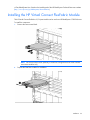
Installing the HP Virtual Connect FlexFabric Module ....................................................................................... 33
Installing a VC-FC module ........................................................................................................................... 35
Installing SFP/SFP+/XFP transceivers ............................................................................................................ 37
Removing SFP/SFP+/XFP transceivers .......................................................................................................... 38
Factory default settings ............................................................................................................................... 38
Connecting Virtual Connect Ethernet module uplinks ...................................................................................... 39
Configuration example using a Cisco Core switch ............................................................................... 42
Failover and check-pointing......................................................................................................................... 44
Interconnect module removal and replacement .............................................................................................. 45
Virtual Connect modules ................................................................................................................... 45
Upgrading to an HP Virtual Connect 8Gb 24-Port FC Module............................................................... 46
Upgrading to an HP Virtual Connect 8Gb 20-Port FC Module............................................................... 46
Upgrading or removing an HP Virtual Connect Flex-10 module or HP Virtual Connect FlexFabric module .. 47
Upgrading to an HP Virtual Connect FlexFabric module from a VC-FC module ....................................... 49
Onboard Administrator modules ........................................................................................................ 49
HP Virtual Connect Manager........................................................................................................ 50
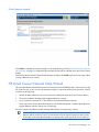
Configuring browser support ....................................................................................................................... 50
Virtual Connect and Insight Control Server Deployment .................................................................................. 51
Accessing HP Virtual Connect Manager ....................................................................................................... 51
Command Line Interface overview...................................................................................................... 52
Contents
3
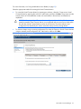
Logging on to the HP Virtual Connect Manager GUI ...................................................................................... 53
About HP Virtual Connect Manager ............................................................................................................. 54
Reset Virtual Connect Manager ................................................................................................................... 54
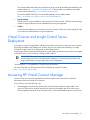
Recovering remote enclosures ............................................................................................................ 54
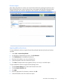
Running the setup wizards........................................................................................................................... 54
HP Virtual Connect Domain Setup Wizard .......................................................................................... 54
HP Virtual Connect Network Setup Wizard ......................................................................................... 64
HP Virtual Connect Fibre Channel Setup Wizard ................................................................................. 78
HP Virtual Connect Manager Server Profile Setup Wizard .................................................................... 84
Verifying data center connections ................................................................................................................ 91
Verify link and speed ........................................................................................................................ 92
Verify network status using VC Manager ............................................................................................ 92
Component identification ............................................................................................................. 93
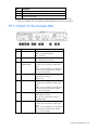
HP 1/10Gb VC-Enet Module components and LEDs ...................................................................................... 93
HP 1/10Gb VC-Enet Module components .......................................................................................... 93
HP 1/10Gb VC-Enet Module LEDs ..................................................................................................... 94
HP 1/10Gb VC-Enet Module system maintenance switch ..................................................................... 95
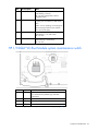
HP 1/10Gb-F VC-Enet Module components and LEDs .................................................................................... 95
HP 1/10Gb-F VC-Enet Module components ........................................................................................ 95
HP 1/10Gb-F VC-Enet Module LEDs................................................................................................... 96
HP 1/10Gb-F VC-Enet Module system maintenance switch ................................................................... 97
HP Virtual Connect Flex-10 10Gb Ethernet Module components and LEDs ....................................................... 98
HP Virtual Connect Flex-10 10Gb Ethernet Module components............................................................ 98
HP Virtual Connect Flex-10 10Gb Ethernet Module LEDs ...................................................................... 99
HP Virtual Connect Flex-10 10Gb Ethernet Module system maintenance switch .................................... 101
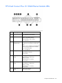
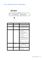
HP Virtual Connect FlexFabric 10Gb/24-port Module components and LEDs ................................................. 102
HP Virtual Connect FlexFabric 10Gb/24-port Module components...................................................... 102
HP Virtual Connect FlexFabric 10Gb/24-port Module LEDs ................................................................ 102
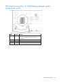
HP Virtual Connect FlexFabric 10Gb/24-port Module system maintenance switch ................................ 105
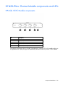
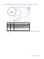
HP 4Gb Fibre Channel Module components and LEDs ................................................................................. 106
HP 4Gb VC-FC Module components ................................................................................................ 106
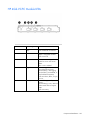
HP 4Gb VC-FC Module LEDs ........................................................................................................... 107
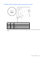
HP 4Gb VC-FC Module system maintenance switch ........................................................................... 108
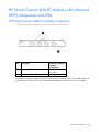
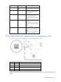
HP Virtual Connect 4Gb FC Module (with enhanced NPIV) components and LEDs .......................................... 109
HP Virtual Connect 4Gb FC Module components .............................................................................. 109
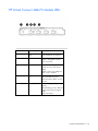
HP Virtual Connect 4Gb FC Module LEDs ......................................................................................... 110
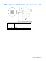
HP Virtual Connect 4Gb FC Module system maintenance switch ......................................................... 111
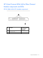
HP Virtual Connect 8Gb 24-Port Fibre Channel Module components and LEDs ............................................... 112
HP VC 8Gb 24-Port FC Module components ..................................................................................... 112
HP VC 8Gb 24-Port FC Module LEDs ............................................................................................... 113
HP VC 8Gb 24-Port FC Module system maintenance switch................................................................ 114
HP Virtual Connect 8Gb 20-Port Fibre Channel Module components and LEDs ............................................... 115
HP VC 8Gb 20-Port FC Module components ..................................................................................... 115
HP VC 8Gb 20-Port FC Module LEDs ............................................................................................... 115
HP VC 8Gb 20-Port FC Module system maintenance switch................................................................ 116
Resetting the Administrator password and DNS settings ............................................................................... 117
Regulatory compliance notices ................................................................................................... 119
Regulatory compliance identification numbers ............................................................................................. 119
Federal Communications Commission notice ............................................................................................... 119
FCC rating label ............................................................................................................................ 119
FCC Notice, Class A Equipment ...................................................................................................... 119
FCC Notice, Class B Equipment ....................................................................................................... 119
Contents
4
Declaration of conformity for products marked with the FCC logo, United States only...................................... 120
Modifications ........................................................................................................................................... 120
Cables .................................................................................................................................................... 120
Canadian notice (Avis Canadien) .............................................................................................................. 120
European Union regulatory notice .............................................................................................................. 121
Disposal of waste equipment by users in private households in the European Union ........................................ 121
Japanese notice ....................................................................................................................................... 122
BSMI notice ............................................................................................................................................. 122
Korean notice .......................................................................................................................................... 122
Chinese notice ......................................................................................................................................... 123
Laser compliance ..................................................................................................................................... 123
Electrostatic discharge ............................................................................................................... 124
Preventing electrostatic discharge .............................................................................................................. 124
Grounding methods to prevent electrostatic discharge .................................................................................. 124
Support and other resources ...................................................................................................... 125
Before you contact HP .............................................................................................................................. 125
HP contact information .............................................................................................................................. 125
Customer Self Repair ................................................................................................................................ 125
Acronyms and abbreviations ...................................................................................................... 133
Documentation feedback ........................................................................................................... 136
Index ....................................................................................................................................... 137
Contents
5
Documentation resources
Virtual Connect documentation
The following Virtual Connect documentation is available on the Installing tab of the HP BladeSystem
Technical Resources website (http://www.hp.com/go/bladesystem/documentation):
•
HP Virtual Connect for c-Class BladeSystem User Guide
This guide provides details for the Virtual Connect GUI, including descriptions of screen contents and
steps to set up domains, profiles, networks, and storage.
•
HP Virtual Connect for c-Class BladeSystem Setup and Installation Guide
This guide provides hardware installation and configuration information for initial setup of a Virtual
Connect solution. The guide also provides Virtual Connect module component and LED descriptions
and guidelines for module installation and upgrades.
•
HP Virtual Connect Manager Command Line Interface for c-Class BladeSystem User Guide
This guide provides information for using the Virtual Connect Command Line Interface, including use
scenarios and complete descriptions of all subcommands and managed elements.
•
HP Virtual Connect Ethernet Cookbook: Single and Multiple Domain (Stacked) Scenarios
This guide helps new Virtual Connect users understand the concepts of and implement steps for
integrating Virtual Connect into a network. The scenarios in this guide vary from simplistic to more
complex while covering a range of typical building blocks to use when designing Virtual Connect
solutions.
•
HP Virtual Connect Fibre Channel Networking Scenarios Cookbook
This guide details the concepts and implementation steps for integrating HP BladeSystem Virtual
Connect Fibre Channel components into an existing SAN fabric. The scenarios in this guide are
simplistic while covering a range of typical building blocks to use when designing a solution.
•
HP Virtual Connect with iSCSI Cookbook
This guide describes how to configure HP Virtual Connect for an iSCSI environment. It provides tips and
troubleshooting information for iSCSI boot and installation.
•
HP BladeSystem c-Class Virtual Connect Support Utility User Guide
This guide provides instructions for using the Virtual Connect Support Utility, which enables
administrators to upgrade VC-Enet and VC-FC firmware and to perform other maintenance tasks
remotely on both HP BladeSystem c7000 and c3000 enclosures using a standalone, Windows-based
command line utility.
•
Release Notes
Release notes document new features, resolved issues, known issues, and important notes for each
release of the Virtual Connect Manager and support utility.
Documentation resources
6
Planning the installation
Virtual Connect overview
HP Virtual Connect is a set of interconnect modules and embedded software for HP BladeSystem c-Class
enclosures that simplifies the setup and administration of server connections. Virtual Connect includes the
following components:
•
•
•
VC-Enet modules
o
HP 1/10Gb Virtual Connect Ethernet Module for c-Class BladeSystem
o
HP 1/10Gb-F Virtual Connect Ethernet Module for the c-Class BladeSystem
o
HP Virtual Connect Flex-10 10Gb Ethernet Module for BladeSystem c-Class
o
HP Virtual Connect FlexFabric 10Gb/24-port Module for BladeSystem c-Class, which provides the
capability to configure Ethernet and FC/FCoE or iSCSI connections
VC-FC modules
o
HP 4Gb Virtual Connect Fibre Channel Module for c-Class BladeSystem
o
HP Virtual Connect 4Gb Fibre Channel Module for BladeSystem c-Class (enhanced NPIV)
o
HP Virtual Connect 8Gb 24-Port Fibre Channel Module for BladeSystem c-Class
o
HP Virtual Connect 8Gb 20-Port Fibre Channel Module for BladeSystem c-Class
HP Virtual Connect Manager
Virtual Connect implements server edge virtualization between the server and the data center infrastructure
so networks can communicate with pools of HP BladeSystem servers, and so you can upgrade, replace, or
move server blades within the enclosures without changes being visible to the external LAN and SAN
environments. The external networks connect to a shared resource pool of servers rather than to individual
servers. Virtual Connect cleanly separates server enclosure administration from LAN and SAN
administration.
VCM is embedded on the VC-Enet module. You can access VCM through a web-based GUI or CLI. The
Onboard Administrator provides a web link to the Virtual Connect GUI.
The VC modules support the HP BladeSystem c7000 Enclosure, the HP BladeSystem c3000 Enclosure, and
all the server blades and networks contained within the enclosure. FlexFabric modules are only supported in
BladeSystem c7000 enclosures and G6 or newer server blades with Virtual Connect firmware v3.15 and
later.
VC-Enet modules enable connectivity to all brands of data center Ethernet switches. VC-Enet modules can
also be directly connected to other types of devices, such as printers, laptops, rack servers, and network
storage devices.
The VC-FC and FlexFabric modules enable connectivity of the enclosure to Brocade, Cisco, McDATA, or
QLogic data center FC switches. Every FC fabric is limited in the number of switches it can support, but the
VC-FC modules do not appear as switches to the FC fabric and do not count against FC fabric limits.
A basic Virtual Connect domain includes a single HP c-Class BladeSystem c7000 Enclosure for a total of 16
servers (or up to 32 servers if the double-dense option is enabled), or a single HP c-Class BladeSystem c3000
Planning the installation
7
Enclosure for a total of 8 servers (or up to 16 servers if the double-dense option is enabled). For more
information on the double-dense option, see "Double-dense server bay option" in the user guide. Within the
domain, any server blade with the requisite LAN or SAN devices can access any LAN or SAN connected to
a VC module, and a server blade of a given processor type (Integrity or X86) can be used as a spare for any
server blade of the same processor type within the same enclosure, as long as the server has the requisite
number and type of connections. Using network access groups feature, the network administrator can clearly
define a separation of networks based on their allowed functionality and prevent the server administrator
from assigning specific network combinations in the same server profile.
By stacking (cabling) the VC-Enet modules together within the domain and connecting the VC-FC or
FlexFabric module FC uplinks on the same bay of all enclosures to the same FC switch, every server blade in
the domain can be configured to access any external network or fabric connection. With this configuration,
you can use VCM to deploy and migrate a server blade profile to any server in the Virtual Connect domain
without changing external LAN or SAN configurations.
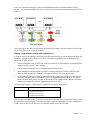
Using multiple enclosures
Multiple enclosure support enables up to four c7000 enclosures to be managed within a single Virtual
Connect domain for a total of 128 servers, if double-dense support is enabled while using the Domain Setup
Wizard. There are 16 half-height or 8 full-height server bays in a c7000 enclosure. A combination of
full-height and half-height servers can be used in the same enclosure.
Multiple enclosure domains are not supported on c3000 enclosures. The VC-Enet or FlexFabric modules use
stacking cables between enclosures so that network traffic can be routed from any server Ethernet port to any
uplink within the VC domain. Since FC does not support stacking, the VC-FC or FlexFabric module FC uplinks
on the same bay of all enclosures must be connected to the same FC switch to enable profile mobility.
The management interfaces for all enclosure Onboard Administrators and VC modules within the same VC
domain must be on the same lightly loaded subnet and highly reliable network. Overloads or loss of
connectivity can disable configuration attempts until the connectivity is re-established and synchronized with
the domain. The Onboard Administrator IP addresses used must be configured to be static. The Onboard
Administrator user credential for all enclosures must be consistent to enable VCSU firmware updates for VC
modules in the remote enclosures. All FC-capable modules in the same horizontally adjacent bay pair (bays
1-2, 3-4, and so on) must be of the same type and position in all enclosures.
Multi-enclosure double-dense domains require similar and compatible VC-FC modules in bays 5, 6, 7, and
8 in all enclosures if FC connectivity is required. If a multi-enclosure double-dense configuration contains
incompatible VC-FC modules in bays 5, 6, 7, or 8 in the local or remote enclosures, some or all of the
compatible VC-FC modules in the remote enclosures might be designated INCOMPATIBLE after import.
Pre-deployment planning
During the planning phase, the LAN and server administrator must determine how each server blade will
connect to the network and on which IP network and VLAN the server will reside. In a traditional network,
these connections are established through physical cables. If a move from one network to another is required,
the cables must also be moved. Virtual Connect provides a wire-once implementation when VC modules are
connected to upstream or core switches and the VC networks and server profiles are defined. Assigning a
server profile to a server blade completes the physical connection to the core network. If a server blade fails
or moves, all of the configuration parameters can be transferred easily to the new server.
Before beginning installation, complete the following tasks:
Planning the installation
8
•
Be sure that the firmware revisions on all VC modules in the domain are at the same revision level. The
active VCM does not allow incompatible modules to be managed as part of the same VC domain. For
more information, see "Firmware requirements (on page 13)."
•
Be sure that OA, iLO, server blade system ROM, Ethernet option ROM, and FC option ROM firmware
are up-to-date. For more information, see "Firmware requirements (on page 13)."
•
Determine which mezzanine cards, HBAs, and interconnect modules are going to be used and where
they will be installed in the enclosure. For installation and information on mapping server ports to
interconnect bays, see the appropriate HP BladeSystem enclosure setup and installation guide on the
Installing tab of the HP BladeSystem Technical Resources website
(http://www.hp.com/go/bladesystem/documentation)
•
Determine the Ethernet stacking cable layout, and ensure that the proper cable and transceiver options
are ordered. Stacking cables enable any Ethernet NIC from any server to be connected to any of the
Ethernet networks defined for the enclosure.
•
o
For information on cable layout, see "Recommended stacking connections (on page 21)."
o
For information on supported cable and transceiver options, see the Virtual Connect module
QuickSpecs on the Installing tab of the HP BladeSystem Technical Resources website
(http://www.hp.com/go/bladesystem/documentation).
Determine which Ethernet networks will be connected to or contained within the enclosure.
Most installations will have multiple Ethernet networks, each typically mapped to a specific IP subnet.
Virtual Connect Ethernet networks can be contained completely within the enclosure for server-to-server
communication, or connected to external networks through rear panel ports (uplinks). For each network,
the administrator must use the VCM to identify the network by name and to define any external port
connections.
•
Determine which Fibre Channel fabrics will be connected to the enclosure.
Each uplink has a capability of aggregating up to 16 server HBA N-port links into an N-port uplink
through the use of NPIV.
•
Coordinate with data center personnel to ensure Ethernet network cable connections and Fibre Channel
cable connections to the enclosure are installed or scheduled to be installed.
•
Determine the Ethernet MAC address range to be used for the servers within the enclosure.
Server and networking administrators should fully understand the selection and use of MAC address
ranges before configuring the enclosure. For more information, see "MAC address settings (on page
65)."
•
Determine the FC World Wide Name (WWN) range to be used for servers within the enclosure.
Server and storage administrators should fully understand the selection and use of WWN ranges before
configuring the enclosure. For more information, see "WWN settings (on page 78)."
•
Identify the administrators for the Virtual Connect environment, and identify what roles and
administrative privileges they will require. The VCM classifies each operation as requiring server,
network, domain, or storage privileges. A single user may have any combination of these privileges.
For more information, see the information on local users in the HP Virtual Connect for c-Class
BladeSystem User Guide on the Installing tab of the HP BladeSystem Technical Resources website
(http://www.hp.com/go/bladesystem/documentation).
IMPORTANT: If you plan on using VC-assigned MAC addresses and WWNs and are also
working with server software that will be licensed by MAC addresses or WWNs, assign server
profiles before deploying an image through RDP or attaching a license.
Planning the installation
9
Hardware setup overview
The following steps provide an overview of setting up the interconnect modules:
1.
Install and set up the enclosure. See the appropriate HP BladeSystem enclosure quick install instructions
on the Installing tab of the HP BladeSystem Technical Resources website
(http://www.hp.com/go/bladesystem/documentation).
2.
Install the interconnect modules ("Installation" on page 13).
Plan your installation carefully. After the VC domain has been created, the position and type of the
primary and backup VC modules cannot be changed without deleting and recreating the domain.
3.
Install stacking links ("Recommended stacking connections" on page 21).
4.
Connect the VC-Enet module uplinks to data center networks. The network administrator should have
already installed the network cables into the rack with the proper labels. See "Connecting Virtual
Connect Ethernet module uplinks (on page 39)."
5.
Connect data center FC fabric links (if applicable).
6.
Note the default DNS name, user name, and password settings for the primary VC module, available
on the module Default Network Settings label.
The primary VC module is the first VC-Enet or FlexFabric module in an odd-numbered interconnect bay.
7.
Note the default DNS name, user name, and password for the HP Onboard Administrator, available on
the module Default Network Settings label. See the HP BladeSystem Onboard Administrator User
Guide on the Installing tab of the HP BladeSystem Technical Resources website
(http://www.hp.com/go/bladesystem/documentation).
8.
Apply power to the enclosures. See "Default module configuration (on page 11)." Also see the
appropriate HP BladeSystem enclosure quick install instructions on the Installing tab of the HP
BladeSystem Technical Resources website (http://www.hp.com/go/bladesystem/documentation).
9.
Use the HP Onboard Administrator for basic setup of the enclosures (including enclosure name and
passwords). See the HP BladeSystem Onboard Administrator User Guide on the Installing tab of the HP
BladeSystem Technical Resources website (http://www.hp.com/go/bladesystem/documentation).
10.
Be sure that all Virtual Connect interconnect module management interfaces and server blade iLO
interfaces have valid IP and gateway addresses using one of the following methods:
o
Run DHCP on the management network connected to the Onboard Administrator.
o
Configure the Onboard Administrator to set enclosure bay IP addresses. See "Virtual Connect and
EBIPA (on page 21)."
11.
Be sure that OA, iLO, server blade system ROM, Ethernet option ROM, and FC option ROM firmware
are up-to-date. For more information, see "Firmware requirements (on page 13)."
12.
Access VCM using one of the following methods:
o
Use a web link from within the Onboard Administrator graphical user interface or use the dynamic
DNS name from the Default Network Settings label. See "Accessing HP Virtual Connect Manager
(on page 51)."
o
Access the VCM CLI remotely through an SSH session. See the HP Virtual Connect Manager
Command Line Interface User Guide on the Installing tab of the HP BladeSystem Technical
Resources website (http://www.hp.com/go/bladesystem/documentation).
Planning the installation
10
IMPORTANT: For proper management of enclosure devices there must be an Ethernet
connection from the Onboard Administrator module to the external management network. For
information on Onboard Administrator module cabling, see the HP BladeSystem Onboard
Administrator User Guide.
Default module configuration
When VC modules are inserted into an enclosure that is not yet part of a Virtual Connect domain, the
modules are configured to provide basic connectivity. After a Virtual Connect domain is defined for an
enclosure, server blades within that enclosure are isolated from all external network and fabric connections
until configured explicitly within VCM.
When not part of a Virtual Connect domain, each VC-Enet module is configured so that all server ports
connected to that module are connected to a single network, which is then connected to a single uplink. To
provide greater bandwidth, you can use LACP to aggregate additional ports on that module, as long as they
are connected to the same external switch. For aggregation of links to an external switch, the external switch
must support dynamic creation of link aggregation groups using the IEEE 802.3ad LACP. All stacking links
are disabled. This default configuration enables connectivity testing between server NICs and devices
outside the enclosure prior to Virtual Connect domain configuration.
When not part of a Virtual Connect domain, all of the VC-FC Module uplink ports are grouped into an uplink
port group and dynamically distribute connectivity from all server blades across all available uplink ports.
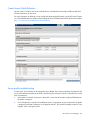
Virtual Connect Manager setup overview
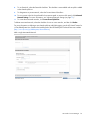
The following steps provide an overview of setting up VCM:
1.
Log in and run the domain setup wizard ("HP Virtual Connect Domain Setup Wizard" on page 54).
a. Import the enclosure.
b. Name the Virtual Connect domain.
c.
Set up local user accounts and privileges.
TIP: If you want to setup network access groups, uncheck the "Start the Network Setup Wizard"
checkbox on the Finish screen of the Domain Setup Wizard.
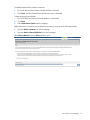
2.
Define network access groups. For more information about network access groups, see "Network
Access Groups screen" in the user guide.
a. Select Network Access Group from the Define pull-down menu.
b. Set up network access groups. For more information about creating network access groups, see
"Define Network Access Group screen" in the user guide.
3.
Run the network setup wizard ("HP Virtual Connect Network Setup Wizard" on page 64).
a. Assign the MAC addresses used by server blade Ethernet network adapters within the Virtual
Connect domain ("MAC Address Settings" on page 65).
b. Configure server VLAN tagging support.
c.
4.
Set up the networks.
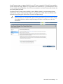
Run the Fibre Channel setup wizard ("HP Virtual Connect Fibre Channel Setup Wizard" on page 78).
a. Select a WWN range to be used by server blade FC HBAs ("WWN settings" on page 78).
b. Define the SAN fabrics.
Planning the installation
11
5.
If you created associated networks using the network setup wizard, all networks are assigned to the
Default network access group. You must be sure that all networks are in the proper network access
group before running the server profile setup wizard. For more information about editing network
access groups, see "Edit Network Access Group screen" in the user guide.
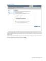
6.
Run the server profile setup wizard ("HP Virtual Connect Manager Server Profile Setup Wizard" on
page 84).
a. Assign serial numbers to server blades within the domain.
b. Create a server profile definition.
c.
Assign server profiles.
d. Name server profiles.
e. Create server profiles.
After an enclosure is imported into a Virtual Connect domain, server blades that have not been assigned a
server profile are isolated from all networks to ensure that only properly configured server blades are
attached to data center networks.
A server profile can be assigned and defined for each device bay so that the server blade can be powered
on and connected to a deployment network. These profiles can then later be modified or replaced by another
server profile.
A server profile can also be assigned to an empty bay to enable deployment at a later date.
Planning the installation
12
Installation
Firmware requirements
IMPORTANT: The active VCM does not allow incompatible modules to be managed as part of
the Virtual Connect domain.
IMPORTANT: For optimal operation of HP Virtual Connect, use the recommended firmware
versions.
Install the recommended firmware for the following items:
•
Server blade system ROMs
•
Ethernet mezzanines
•
Converged network adapter mezzanines
•
HP BladeSystem Onboard Administrator
Server blades and mezzanine cards can be updated before the domain is created using the default network
configuration on the VC-Enet modules. After the domain is created, the server blades are isolated from fabrics
and networks until a profile is assigned to the server blade.
For more information on recommended firmware versions, to download firmware upgrades, and to
download the HP BladeSystem for ProLiant Firmware Management Best Practices Implementer Guide, see the
HP website (http://www.hp.com/go/bladesystemupdates).
Installation guidelines
CAUTION: Always use blanks to fill empty spaces in enclosures. This arrangement ensures
proper airflow. Using an enclosure without the proper blanks results in improper cooling that can
lead to thermal damage.
Observe the following guidelines:
•
In all Virtual Connect configurations, a VC-Enet or FlexFabric module must be installed in the enclosure.
The embedded VCM operates on this module.
•
VC-Enet modules are used typically in pairs to provide access to all Ethernet controllers on the server
blade.
•
The specific interconnect bays with Ethernet connectivity depend on mezzanine card locations within
the server blade.
•
For c3000 enclosures, when two Fibre Channel mezzanine cards are installed in slots 2 and 3 of a
full-height server blade, the VC Manager only creates Fibre Channel connections and assigns WWNs
to the ports associated with the Fibre Channel mezzanine card in slot 2. This restriction does not apply
for c7000 enclosures.
Installation
13
•
For each Ethernet mezzanine port you want to manage with VCM, install a VC-Enet or HP VC FlexFabric
10Gb/24-port Module in the interconnect bay connected to that port. For more information, see the
appropriate HP BladeSystem enclosure setup and installation guide.
•
For Ethernet connections, Virtual Connect can be configured to assign or migrate MAC addresses for
device bay ports connected to VC-Enet or FlexFabric modules.
•
For Fibre Channel connections, FlexFabric module SFP ports can be connected only to Fibre Channel
switch ports that support N_port_ID virtualization. To verify that NPIV support is provided, see the
firmware documentation that ships with the Fibre Channel switch.
•
When using optional transceiver modules, or when using stacking cables to connect multiple VC-Enet
modules or multiple FlexFabric modules, order the cables and transceiver modules separately. For more
information, see the HP Virtual Connect QuickSpecs on the Installing tab of the HP BladeSystem
Technical Resources website (http://www.hp.com/go/bladesystem/documentation).
•
All modules in the enclosure require a valid and unique IP address, and all modules must be on the same
subnet. Use a DHCP server or the Onboard Administrator EBIPA feature to assign each module an IP
address.
•
For server or I/O interconnect hardware changes that involve adding or removing Flex-10 functionality,
the profile assigned to a server or server bay must be removed, all hardware changes performed, and
the profile reassigned. Otherwise, indeterminate network operation might occur. For more information,
see "Upgrading or removing an HP Virtual Connect Flex-10 Module or HP Virtual Connect FlexFabric
Module (on page 47)."
Additional information
•
For the most up-to-date support information, see the HP website (http://www.hp.com/storage/spock).
Simple registration is required.
•
For more information on the association between the server blade mezzanine connectors and the
interconnect bays, see the HP BladeSystem enclosure setup and installation guide that ships with the
enclosure. During server blade installation, the location of the mezzanine card determines the
installation location of the interconnect modules.
•
For specific interconnect module port connection information for each server blade, see the HP
BladeSystem enclosure setup and installation guide that ships with the enclosure. Connections differ by
server blade type.
•
For more information on BladeSystem port mapping, see the HP BladeSystem enclosure setup and
installation guide that ships with the enclosure.
•
For the most current product information, see the release notes on the Installing tab of the HP
BladeSystem Technical Resources website (http://www.hp.com/go/bladesystem/documentation).
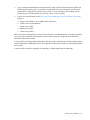
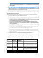
Supported configurations
The following table outlines the Ethernet, Fibre Channel, and enclosure support for each version of Virtual
Connect.
VC firmware
version
Enclosure
FlexFabric
Support
Ethernet
support
FC support
Enclosures per
single VC
domain
1.10
c3000
—
—
—
—
1.10
c7000
—
Up to 8 modules Up to 4 modules 1
Installation
14
VC firmware
version
Enclosure
FlexFabric
Support
Ethernet
support
FC support
1.20
c3000
—
Up to 4 modules Up to 2 modules 1
2.10
c7000
—
2.10
c3000
—
Up to 16
Up to 16
Up to 4
modules
modules
Up to 4 modules Up to 2 modules 1
3.00
c7000
—
3.00
c3000
—
3.10
c7000
—
3.10
c3000
—
Up to 16
Up to 16
Up to 4
modules
modules
Up to 4 modules Up to 2 modules 1
3.15/3.17
c7000
3.15/3.17
c3000
Up to 16
modules
—
Up to 16
Up to 16
Up to 4
modules
modules
Up to 4 modules Up to 2 modules 1
3.30
c7000
3.30
c3000
Up to 16
modules
—
Up to 16
Up to 16
Up to 4
modules
modules
Up to 4 modules Up to 2 modules 1
3.51
c7000
3.51
c3000
Up to 16
modules
—
Up to 16
Up to 16
Up to 4
modules
modules
Up to 4 modules Up to 2 modules 1
3.60
c7000
3.60
c3000
Up to 16
modules
—
Up to 16
Up to 16
Up to 4
modules
modules
Up to 4 modules Up to 2 modules 1
Enclosures per
single VC
domain
Up to 16
Up to 16
Up to 4
modules
modules
Up to 4 modules Up to 2 modules 1
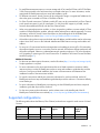
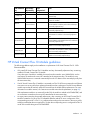
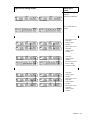
HP BladeSystem c7000 Enclosure supported configurations
The following tables show a number of typical, supported configurations for an HP BladeSystem c7000
Enclosure.
In the following tables, "Other" indicates any c-Class interconnect module including a VC, Pass-Thru, or
switch.
[Bay 1]
VC Ethernet
[Bay 2]
Empty
[Bay 3]
Other/empty
[Bay 4]
Other/empty
[Bay 5]
Other/empty
[Bay 6]
Other/empty
[Bay 7]
Other/empty
[Bay 8]
Other/empty
[Bay 1]
VC Ethernet
[Bay 2]
VC Ethernet
[Bay 3]
Other/empty
[Bay 4]
Other/empty
[Bay 5]
Other/empty
[Bay 6]
Other/empty
[Bay 7]
Other/empty
[Bay 8]
Other/empty
[Bay 1]
Other/empty
[Bay 2]
Other/empty
[Bay 3]
VC Ethernet*
[Bay 4]
VC Ethernet
[Bay 5]
Other/empty
[Bay 6]
Other/empty
Other/empty
[Bay 8]
Other/empty
[Bay 7]
*Requires minimum VC v3.10 firmware
Installation
15
[Bay 1]
VC Ethernet
[Bay 2]
VC Ethernet
[Bay 3]
Other/empty
[Bay 4]
Other/empty
[Bay 5]
VC Ethernet
[Bay 6]
VC Ethernet
[Bay 7]
Other/empty
[Bay 8]
Other/empty
[Bay 1]
VC Ethernet
[Bay 2]
VC Ethernet
[Bay 3]
VC Ethernet
[Bay 4]
VC Ethernet
[Bay 5]
VC Ethernet
[Bay 6]
VC Ethernet
[Bay 7]
Other/empty
[Bay 8]
Other/empty
[Bay 1]
VC Ethernet
[Bay 2]
Empty
[Bay 3]
VC-FC
[Bay 4]
Empty
[Bay 5]
Other/empty
[Bay 6]
Other/empty
[Bay 7]
Other/empty
[Bay 8]
Other/empty
[Bay 1]
VC Ethernet
[Bay 2]
VC Ethernet
[Bay 3]
VC-FC
[Bay 4]
VC-FC
[Bay 5]
Other/empty
[Bay 6]
Other/empty
[Bay 7]
Other/empty
[Bay 8]
Other/empty
[Bay 1]
VC Ethernet
[Bay 2]
VC Ethernet
[Bay 3]
VC Ethernet
[Bay 4]
VC Ethernet
[Bay 5]
VC-FC
[Bay 6]
VC-FC
[Bay 7]
Other/empty
[Bay 8]
Other/empty
[Bay 1]
VC Ethernet*
[Bay 2]
VC Ethernet
[Bay 3]
VC Ethernet
[Bay 4]
VC Ethernet
VC-FC
[Bay 6]
VC-FC
[Bay 5]
[Bay 8]
VC-FC
[Bay 7]
VC-FC
* This configuration only applies to enclosures with full-height servers.
VC Ethernet
[Bay 2]
VC Ethernet
[Bay 3]
VC-FC
[Bay 4]
VC-FC
[Bay 5]
VC Ethernet
[Bay 6]
VC Ethernet
[Bay 7]
Other/empty
[Bay 8]
Other/empty
[Bay 1]
VC Ethernet
[Bay 2]
VC Ethernet
[Bay 3]
VC-FC
[Bay 4]
VC-FC
[Bay 5]
VC Ethernet
[Bay 6]
VC Ethernet
[Bay 7]
VC Ethernet
[Bay 8]
VC Ethernet
[Bay 1]
VC Ethernet
[Bay 2]
VC Ethernet
[Bay 3]
Other/empty
[Bay 4]
Other/empty
[Bay 5]
VC-FC
[Bay 6]
VC-FC
[Bay 7]
Other/empty
[Bay 8]
Other/empty
[Bay 1]
VC Ethernet
[Bay 2]
VC Ethernet
[Bay 3]
VC-FC
[Bay 4]
VC-FC
[Bay 5]
VC-FC
[Bay 6]
VC-FC
[Bay 1]
Installation
16
[Bay 7]
Other/empty
[Bay 8]
Other/empty
[Bay 1]
VC Ethernet
[Bay 2]
VC Ethernet
[Bay 3]
VC Ethernet
[Bay 4]
VC Ethernet
[Bay 5]
VC Ethernet
[Bay 6]
VC Ethernet
[Bay 7]
VC Ethernet
[Bay 8]
VC Ethernet
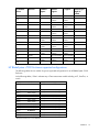
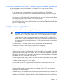
HP BladeSystem c3000 Enclosure supported configurations
The following tables show several typical, supported configurations for an HP BladeSystem c3000 Enclosure.
In the following tables, "Other" indicates any c-Class interconnect module including a VC, Pass-Thru, or
switch.
VC Ethernet
[Bay 2]
VC Ethernet
[Bay 3]
Other/empty
[Bay 4]
Other/empty
[Bay 1]
VC Ethernet
[Bay 2]
VC Ethernet
[Bay 3]
VC Ethernet
[Bay 4]
VC Ethernet
[Bay 1]
VC Ethernet
[Bay 2]
VC Ethernet
[Bay 3]
VC-FC
[Bay 4]
VC-FC
[Bay 1]
Other/empty
[Bay 2]
Other/empty
[Bay 3]
VC Ethernet
[Bay 4]
VC Ethernet
[Bay 1]
IMPORTANT: The HP Virtual Connect FlexFabric 10Gb 24-port Module is not supported in
c3000 enclosures.
The use of an HP VC-Enet in bay 1 and a Fibre Channel module (for example, VC-FC, SNA
switch, or FC pass-thru) in bay 2 is not supported in c3000 enclosures.
Bay configuration guidelines
Primary and backup VC modules
Observe the following guidelines when installing primary and backup interconnect modules:
•
Plan your installation carefully. After the VC domain has been created, the position and type of the
primary and backup VC modules cannot be changed without deleting and recreating the domain.
IMPORTANT: The primary bay pair cannot be changed after the domain is created, including
through a restore configuration file operation.
•
To support failover configuration for VCM, install two VC-Enet modules or two FlexFabric modules in
horizontally adjacent bays.
•
To support high availability of the Virtual Connect environment, HP recommends that VC-Enet modules
be used in horizontally adjacent interconnect bays. The embedded VCM operates in an active/standby
configuration. For more information, see "Failover and check-pointing (on page 44)."
IMPORTANT: In a single enclosure domain, HP recommends that you do not manage the VC
domain from HP 1/10 Gb VC-Enet Modules or HP 1/10 Gb-F Ethernet Modules if FlexFabric
modules exist in the same enclosure.
In a multi-enclosure domain, you cannot manage the VC domain from HP 1/10 Gb VC-Enet
Installation
17
Modules or HP 1/10 Gb-F Ethernet Modules if HP VC Flex-10 and FlexFabric modules are present
in the same enclosure. However, homogeneous 1/10 Gb module multi-enclosure configurations
are acceptable.
•
To set up and configure VCM, an odd-numbered interconnect bay must be populated with a VC-Enet
module or FlexFabric module. The lowest odd-numbered interconnect bay populated with a VC-Enet
module or FlexFabric module becomes the primary VC module.
•
If the OA Administrator has configured VLANs for I/O modules, the primary and backup VC modules
must be installed in bays 1 and 2. This constraint will be removed when OA 3.21 or higher is installed.
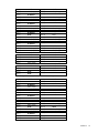
Horizontally adjacent interconnect bays
Observe the following guidelines when installing interconnect modules in horizontally adjacent bays:
•
Only like VC modules can reside in adjacent horizontal bays.
o
If a VC-Enet module is installed in an interconnect bay, the only module that can be installed in the
horizontally adjacent bay is another VC-Enet module of the same type.
o
HP Virtual Connect Flex-10 10Gb Ethernet Modules can reside in any bay. However, only another
Flex-10 10Gb Ethernet Module can reside in an adjacent bay.
o
HP 1/10 Gb VC-Enet Modules and HP 1/10 Gb-F Ethernet Modules can reside in any bay.
However, only another HP 1/10 Gb VC-Enet Module or an HP 1/10 Gb-F Ethernet Module can
reside in an adjacent bay.
o
HP VC 8Gb 20-Port FC Modules can reside in any bay. However, only another HP VC 8Gb 20-Port
FC Module can reside in an adjacent bay.
o
HP Virtual Connect 8Gb 24-Port Fibre Channel Modules can reside in any bay. However, only
another 8Gb 24-Port Fibre Channel Module can reside in an adjacent bay.
o
Do not mix HP Virtual Connect 8Gb 24-Port FC Modules with HP Virtual Connect 4Gb or 8Gb
20-Port FC Modules in the horizontally adjacent interconnect bays connected to the same server
blade mezzanine card.
•
For c3000 enclosures, VC-FC modules are not supported in interconnect bay 2.
•
To avoid connectivity loss, do not install VC and non-VC modules in interconnect bays connected to the
same server blade mezzanine card. Non-VC modules cannot be installed in an adjacent interconnect
bay.
•
Do not mix VC-Enet modules and VC-FC modules in interconnect bays connected to the same server
blade mezzanine card. This action generates an enclosure electronic keying error.
Odd numbered
bay
Horizontally
adjacent bay
Good
configuration?
Notes
VC FlexFabric
10Gb/24-port
VC FlexFabric
10Gb/24-port
Yes
—
VC FlexFabric
10Gb/24-port
Flex-10 Enet
No
Only install VC FlexFabric 10Gb/24-port modules
into bays horizontally adjacent to bays containing
VC FlexFabric 10Gb/24-port modules.
Flex-10 Enet
Flex-10 Enet
Yes
—
Flex-10 Enet
1/10Gb-F Enet
No
Only install HP Flex-10 10Gb VC-Enet modules into
bays horizontally adjacent to bays containing HP
Flex-10 10Gb VC-Enet modules.
1/10Gb-F Enet
1/10Gb-F Enet
Yes
—
1/10Gb Enet
1/10Gb Enet
Yes
—
Installation
18
Odd numbered
bay
Horizontally
adjacent bay
Good
configuration?
Notes
1/10Gb-F Enet
1/10Gb Enet
Yes
—
1/10Gb Enet
4Gb FC
No
Do not mix Ethernet and FC modules in horizontally
adjacent bays.
4Gb FC
4Gb FC
Yes
Bays 3 and 4 of adjacent enclosures must also
contain FC modules.
4Gb FC
4Gb FC with
enhanced NPIV
Yes
You can mix HP 4Gb VC-FC modules and HP Virtual
Connect 4Gb FC modules (with enhanced NPIV) in
horizontally adjacent bays.
4Gb FC
8Gb 24-Port FC
No
Do not mix 4Gb FC and 8Gb 24-Port FC modules in
horizontally adjacent bays.
4Gb FC
8Gb 20-Port FC
Yes
You can mix HP VC 4Gb VC-FC modules and HP
8Gb 20-Port FC modules in horizontally adjacent
bays.
4Gb FC with
enhanced NPIV
8Gb 20-Port FC
Yes
You can mix HP VC 4Gb FC modules (with
enhanced NPIV) and HP 8Gb 20-Port FC modules in
horizontally adjacent bays.
8Gb 24-Port FC
8Gb 20-Port FC
No
Do not mix HP 8Gb 24-Port FC and 8Gb 20-Port FC
modules in horizontally adjacent bays.
VC FlexFabric
10Gb/24-port
8Gb 20-Port FC
No
The VC FlexFabric 10Gb/24-port module can only
have another VC FlexFabric 10Gb/24-port module
in the horizontally adjacent bay.
No
Do not mix VC and non-VC (switch or pass-thru)
modules in horizontally adjacent bays.
VC-Enet or VC-FC non-VC Other
HP Virtual Connect Flex-10 Module guidelines
The following guidelines apply to the installation or replacement of HP Virtual Connect Flex-10 10Gb
Ethernet Modules:
•
Only install HP Virtual Connect Flex-10 Modules into bays horizontally adjacent to bays containing
another HP Virtual Connect Flex-10 Module.
If any other type of module is installed, the second one discovered is set to UNKNOWN, and no
connections are made to the server NICs attached to the interconnect bay. The module is set to
UNKNOWN because it is removed automatically from the VC domain when removed physically from
the interconnect bay.
•
If an HP Virtual Connect Flex-10 Module is connected to a Flex-10 NIC that corresponds to an Ethernet
connection in a server profile, then replacing the module with any other type of Virtual Connect Ethernet
module requires that all network uplinks be removed from the module before replacement. For more
information on module removal, see "Interconnect module removal and replacement (on page 45)."
If the replacement module is not removed from the GUI, the module is marked as INCOMPATIBLE, and
no connections are made to the server NICs attached to the interconnect bay.
•
An empty interconnect bay horizontally adjacent to a bay containing an HP Virtual Connect Flex-10
Module is treated as if it has a Flex-10-compatible Ethernet module for server configuration. If the
corresponding server NIC is Flex-10, it is partitioned according to the connections in the server profile.
Adding a module that does not support Flex-10 when the corresponding server is configured for Flex-10
results in the module being set to INCOMPATIBLE.
Installation
19
HP Virtual Connect FlexFabric 10Gb/24-port Module guidelines
The following guidelines apply to the installation or replacement of HP Virtual Connect FlexFabric
10Gb/24-port Modules:
•
For full storage network compatibility, each server blade attached to the HP VC FlexFabric
10Gb/24-port Module must have either an embedded or mezzanine-based FlexFabric converged
network adapter.
•
Only install an HP VC FlexFabric 10Gb/24-port Module in an interconnect bay horizontally adjacent
to a bay that contains an HP VC FlexFabric 10Gb/24-port Module.
•
The HP VC FlexFabric 10Gb/24-port Module only supports external stacking for Ethernet traffic. When
the HP VC FlexFabric 10Gb/24-port Module has ports configured to carry Fibre Channel traffic, those
ports do not support stacking.
Multiple enclosure guidelines
Observe the following guidelines when connecting multiple enclosures:
•
Each enclosure must have at least one VC-Enet, Flex-10, or FlexFabric module installed.
IMPORTANT: In a single enclosure domain, HP recommends that you do not manage the VC
domain from HP 1/10 Gb VC-Enet Modules or HP 1/10 Gb-F Ethernet Modules if FlexFabric
modules exist in the same enclosure.
In a multi-enclosure domain, you cannot manage the VC domain from HP 1/10 Gb VC-Enet
Modules or HP 1/10 Gb-F Ethernet Modules if HP VC Flex-10 and FlexFabric modules are present
in the same enclosure. However, homogeneous 1/10 Gb module multi-enclosure configurations
are acceptable.
•
All VC-Enet, Flex-10, or FlexFabric modules must be interconnected (redundantly stacked).
•
All enclosures must have the same FC and FlexFabric module configuration.
•
A single domain supports up to four c7000 enclosures.
•
When using multiple c7000 enclosures, the number of modules supported across the enclosures within
a domain is limited. A total of 16 Ethernet and 16 VC-FC type modules can be installed. A FlexFabric
module counts as 1 Ethernet and 1 VC-FC module. Thus, up to 16 FlexFabric Modules or combinations
of FlexFabric, VC-Enet, and VC-FC modules are allowed as long as the 16-module limit for each module
type (Ethernet and FC) is not exceeded in the domain.
•
All Onboard Administrators and VC modules must be on the same lightly loaded and highly reliable
management Ethernet network and IP subnet.
•
VC modules must be running VCM v3.15 or higher.
•
The VC-FC and FlexFabric FC-configured uplink port configuration must be identical across all
enclosures.
•
The Onboard Administrator firmware must be version 3.11 or higher.
•
All Onboard Administrators must use the same user credentials because VCSU uses the primary
credentials for the remote enclosure.
•
When both Primary and Standby modules in the base enclosure are taken down for maintenance or
lose power and are no longer present in the domain, you will experience a loss of the management
capabilities in the VC domain. If network and fabric uplinks were defined on the remaining enclosures,
Installation
20
the servers continue to have network and storage access. Both the Primary and Standby modules in the
base enclosure must be recovered to regain management access to the VC domain.
Virtual Connect and EBIPA
Enclosure Bay IP Addressing is used to specify IP addresses for the interconnect modules, which are then
provided to the modules by the Onboard Administrator.
Because Virtual Connect communicates with other components through the Onboard Administrator, special
considerations are required when using EBIPA with Virtual Connect Ethernet modules:
•
The Onboard Administrator must be on the same IP subnet as all Virtual Connect modules.
•
The Onboard Administrator IP address must be set properly before changing the IP addresses of the
Virtual Connect modules.
Recommended stacking connections
Stacking links are used to add VC-Enet modules into a Virtual Connect domain. This feature enables all
Ethernet network controllers on all servers in the Virtual Connect domain to have access to any VC-Enet
module uplink port. By using these module-to-module links, a single pair of uplinks can function as the data
center network connections for the entire Virtual Connect domain. Stacking enables any server NIC
connected physically to a VC module to be connected to any Ethernet network.
Each interconnect module has several numbered Ethernet connectors. All of these connectors can be used to
connect to data center switches, or they can be used to stack VC modules and enclosures.
The HP VC FlexFabric 10Gb/24-port Module only supports external stacking for Ethernet traffic. When the
HP VC FlexFabric 10Gb/24-port Module has ports configured to carry Fibre Channel traffic, those ports do
not support stacking.
Virtual Connect automatically detects when one VC-Enet module port is connected to another VC-Enet
module port within the domain and changes the port ID indicator to amber.
All VC-Enet modules within the Virtual Connect domain must be interconnected. Any combination of 1-Gb
and 10-Gb cables can be used to interconnect the modules. However, the following table provides
recommended configurations for two, four, six, or eight VC-Enet modules. A 10-Gb stacking link is already
provided on the enclosure midplane for horizontally adjacent VC-Enet modules (bays 1 and 2, 3 and 4, 5
and 6, or 7 and 8 of the c7000 enclosure, or bays 1 and 2, or 3 and 4 of the c3000 enclosure).
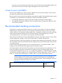
NOTE: Port X0 is the 10Gb port connected through the midplane of horizontally-adjacent
VC-Enet modules. Port X7 and x8 connect to the internal link between horizontally-adjacent
Flex-10 or FlexFabric enabled Virtual Connect Ethernet modules. These ports appear in the list of
stacking link connections within the user interface.
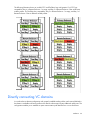
Single enclosure stacking diagram
Modules (top to
bottom)
Stacking two modules
Installation
21
Single enclosure stacking diagram
Modules (top to
bottom)
HP Virtual Connect
FlexFabric
10Gb/24-port Modules
HP Virtual Connect
Flex-10 10Gb Ethernet
Modules
Stacking four modules
•
•
•
•
HP Virtual Connect
FlexFabric
10Gb/24-port
Modules
HP Virtual Connect
FlexFabric
10Gb/24-port
Modules
HP Virtual Connect
FlexFabric
10Gb/24-port
Modules
HP Virtual Connect
Flex-10 10Gb
Ethernet Modules
Stacking six modules
•
•
•
HP Virtual Connect
FlexFabric
10Gb/24-port
Modules
HP Virtual Connect
FlexFabric
10Gb/24-port
Modules
HP Virtual Connect
FlexFabric
10Gb/24-port
Modules
Installation
22
Single enclosure stacking diagram
Modules (top to
bottom)
•
•
•
•
•
•
HP Virtual Connect
FlexFabric
10Gb/24-port
Modules
HP Virtual Connect
FlexFabric
10Gb/24-port
Modules
HP Virtual Connect
Flex-10 10Gb
Ethernet Modules
HP Virtual Connect
FlexFabric
10Gb/24-port
Modules
HP Virtual Connect
Flex-10 10Gb
Ethernet Modules
HP 1/10Gb-F
VC-Enet Modules*
Stacking eight modules
•
•
•
•
•
•
•
•
HP Virtual Connect
FlexFabric
10Gb/24-port
Modules
HP Virtual Connect
FlexFabric
10Gb/24-port
Modules
HP Virtual Connect
FlexFabric
10Gb/24-port
Modules
HP Virtual Connect
FlexFabric
10Gb/24-port
Modules
HP Virtual Connect
FlexFabric
10Gb/24-port
Modules
HP Virtual Connect
FlexFabric
10Gb/24-port
Modules
HP Virtual Connect
Flex-10 10Gb
Ethernet Modules
HP Virtual Connect
Flex-10 10Gb
Installation
23
Single enclosure stacking diagram
Modules (top to
bottom)
Ethernet Modules
*HP 1/10Gb VC-Enet Modules and HP 1/10 Gb-F Ethernet Modules are not supported as primary and backup modules
in multi-enclosure configurations. For optimal VC Manager performance, HP Virtual Connect FlexFabric 10Gb/24-port
Modules or HP Virtual Connect Flex-10 10Gb Ethernet Modules should be designated as primary and backup modules
over HP 1/10Gb VC-Enet Modules and HP 1/10 Gb-F Ethernet Modules in a single-enclosure configuration, when
possible.
VC-Enet modules support 0.5 m to 7 m (1.64 ft to 23.00 ft) 10GBASE-CX4 stacking cables. The 1000BASE-T
links can also be used as stacking links of up to 100 m (328 ft). Ports with different connector types can be
aggregated if the link speed is the same. For example, CX4 and SFP+ ports both running at 10G can be
aggregated to provide enhanced throughput for the stacking link.
NOTE: The CX4 interface uses the same physical connector as Infiniband, but Infiniband cables
are tuned differently and will not perform as well in CX4 applications. HP recommends
purchasing CX4 cable assemblies that meet the IEEE CX4 specifications and support 10-Gigabit
communication at distances from 3 m to 15 m (9.84 ft to 49.20 ft).
FlexFabric modules support DAC cables. Uplink ports X1-X4 only support 0.5 m to 5m (1.64 ft to 16.40 ft)
DAC stacking or uplink cables. Uplink Ports X5-X8 support 0.5 m to 7 m (1.64 ft to 23.00 ft) DAC stacking
or uplink cables.
HP recommends fully redundant interconnection of VC-Enet modules. The recommended stacking
configurations have redundant connections. If a stacking cable is disconnected or fails, the Ethernet packets
within the Virtual Connect domain are automatically re-routed to the uplink through the redundant path. This
configuration also helps preserve network connectivity if an Ethernet interconnect module fails or is removed.
Network loop protection
To avoid network loops, Virtual Connect first verifies that only one active uplink exists per network from the
Virtual Connect domain to the external Ethernet switching environment. Second, Virtual Connect makes sure
that no network loops are created by the stacking links between Virtual Connect modules.
•
One active link—A VC uplink set can include multiple uplink ports. To prevent a loop with broadcast
traffic coming in one uplink and going out another, only one uplink or uplink LAG is active at a time. The
uplink or LAG with the greatest bandwidth should be selected as the active uplink. If the active uplink
loses the link, then the next best uplink is made active.
•
No loops through stacking links—If multiple VC-Enet modules are used, they are interconnected using
stacking links, which might appear as an opportunity for loops within the VC environment. For each
individual network in the Virtual Connect environment, VC blocks certain stacking links to ensure that
each network has a loop-free topology.
Enhanced network loop protection detects loops on downlink ports, which can be a Flex-10 logical port or
physical port. The feature applies to Flex-10 logical function if the Flex-10 port is operating under the control
of DCC protocol. If DCC is not available, the feature applies to a physical downlink port.
Enhanced network loop protection uses two methods to detect loops:
•
It periodically injects a special probe frame into the VC domain and monitors downlink ports for the
looped back probe frame. If this special probe frame is detected on downlink ports, the port is
considered to cause the loop condition.
Installation
24
•
It monitors and intercepts common loop detection frames used in other switches. In network
environments where the upstream switches send loop detection frames, the VC Enet modules must
ensure that any downlink loops do not cause these frames to be sent back to the uplink ports. Even
though VC probe frames ensure loops are detected, there is a small time window depending on the
probe frame transmission interval in which the loop detection frames from the external switch might loop
through down link ports and reach uplink ports. By intercepting the external loop detection frames on
downlinks, the possibility of triggering loop protection on the upstream switch is eliminated. When
network loop protection is enabled, VC-Enet modules intercept the following types of loop detection
frames:
o
PVST+ BPDUs
o
Procurve Loop Protect frames
When the network loop protection feature is enabled, any probe frame or other supported loop detection
frame received on a downlink port is considered to be causing the network loop, and the port is disabled
immediately until an administrative action is taken. The administrative action involves resolving the loop
condition and clearing the loop protection error condition. The "loop detected" status on a port can be
cleared by one of the following administrative actions:
•
Restart loop detection by issuing "reset" loop protection from the CLI or GUI
•
Unassign all networks from the port in "loop detected" state
The SNMP agent supports trap generation when a loop condition is detected or cleared.
Virtual Connect provides the ability to enable or disable network loop protection. The feature is enabled by
default and applies to all VC-Enet modules in the domain. Network loops are detected and server ports can
be disabled even prior to any enclosure being imported.
A loop-protect reset command resets and restarts loop detection for all server ports in a “loop-detected” error
condition.
For each individual network in the Virtual Connect environment, VC blocks certain stacking links to ensure
that each network has a loop-free topology. VCM determines which stacking links are used to forward traffic
by determining the shortest route from the module with the active uplink to the remaining stacked VC-Enet
modules. For optimal stacking strategies, see HP Virtual Connect for the Cisco Network Administrator on the
Functionality & Value tab of the HP BladeSystem Technical Resources website
(http://www.hp.com/go/bladesystem/documentation).
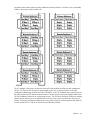
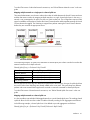
Connecting multiple enclosures
Virtual Connect version 2.10 and higher supports the connection of up to four c7000 enclosures, which can
reduce the number of network connections per rack and also enables a single VC manager to control multiple
enclosures. A single set of cables can be used to carry all external Ethernet traffic from a single rack.
Multiple enclosure support enables up to four c7000 enclosures to be managed within a single Virtual
Connect domain. This configuration supports up to 16 VC-Enet modules and up to 16 VC-FC modules in the
same domain, with a maximum of 4 VC-Enet, or 4 VC-FC modules per enclosure. Using multiple c7000
enclosures, you can install up to 16 FlexFabric modules in the same domain. Each FlexFabric Module counts
as 1 VC-Enet module and 1 VC-FC module towards the 16 maximum module limit per multi-enclosure
domain.
Stacking multiple enclosures enables the management of up to four enclosures from a single control point. VC
Manager operates in the primary enclosure, and it enables up to three additional remote enclosures of the
same type to be added as part of a single VC domain. The locally managed primary enclosure must be
Installation
25
imported into the domain before importing additional (remote) enclosures. If a failure occurs, the standby
module in the primary enclosure takes over.
The VC manager in the primary enclosure accesses all remote modules and OAs over the management
network. The OAs for each enclosure to be managed as part of a VC domain must be on the same
management subnet along with all of the VC-Enet, FlexFabric, and VC-FC modules that are in each enclosure.
All enclosure OAs and VC modules within the same VC domain must be on the same lightly loaded subnet.
The OA IP addresses used must be configured to be static. The VC-Enet or FlexFabric modules use stacking
cables between enclosures to route network traffic from any server port to any uplink port within the VC
domain. The primary and backup module bays in the primary enclosure must be populated with either HP
Virtual Connect Flex-10 10Gb or HP Virtual Connect FlexFabric modules.
Installation
26
IMPORTANT: In a single enclosure domain, HP recommends that you do not manage the VC
domain from HP 1/10 Gb VC-Enet Modules or HP 1/10 Gb-F Ethernet Modules if FlexFabric
modules exist in the same enclosure.
In a multi-enclosure domain, you cannot manage the VC domain from HP 1/10 Gb VC-Enet
Modules or HP 1/10 Gb-F Ethernet Modules if HP VC Flex-10 and FlexFabric modules are present
in the same enclosure. However, homogeneous 1/10 Gb module multi-enclosure configurations
are acceptable.
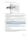
The VC-FC modules and FlexFabric FC-configured ports do not support stacking. Connecting multiple
enclosures requires identical FC and FlexFabric module bay configuration in each enclosure. For more
information, see "FC and FlexFabric bay configuration using multiple enclosures (on page 27)."
Multi-enclosure double dense domains require similar and compatible FC modules in bays 5, 6, 7, and 8 in
all enclosures. If a multi-enclosure double dense configuration contains incompatible FC modules in bays 5,
6, 7, or 8 in either the local or remote enclosures, some or all of the compatible FC modules in the remote
enclosures might be designated INCOMPATIBLE after import.
To add additional enclosures to a domain, see the HP Virtual Connect for c-Class BladeSystem User Guide
on the Installing tab of the HP BladeSystem Technical Resources website
(http://www.hp.com/go/bladesystem/documentation).
FC and FlexFabric bay configuration using multiple enclosures
The VC-FC modules and FlexFabric FC-configured uplinks do not support stacking. To ensure server profile
mobility, the VC-FC and FlexFabric bay configurations must be identical for all enclosures in the domain.
Installation
27
For example, in a multi-enclosure domain with a total of four enclosures, if bays 3 and 4 of the Primary
Enclosure contain VC-FC modules, then bays 3 and 4 of Remote Enclosures 1, 2, and 3 must also contain
VC-FC modules. If bays 1 and 2 of the Primary Enclosure contain FlexFabric modules, then bays 1 and 2 of
Remote Enclosures 1, 2, and 3 must also contain FlexFabric modules. The following illustration shows a valid
VC-FC and FlexFabric bay configuration.
Installation
28
The following illustration shows an invalid VC-FC and FlexFabric bay configuration. For VC-FC bay
compatibility, Bay 4 in Remote Enclosure 1 is empty, and Bay 3 of Remote Enclosure 2 has an Ethernet
module present. For FlexFabric bay compatibility, Bay 2 in Remote Enclosure 1 is empty, and Bay 1 of
Remote Enclosure 2 has an Ethernet module present.
Directly connecting VC domains
In a multi-enclosure domain configuration with properly installed stacking cables, each network defined in
the domain is available to all server profiles in the domain without requiring any additional uplink ports. This
configuration enables you to establish an open communication path between two or more enclosures.
Installation
29
You can also directly associate the uplinks from two enclosures from different domains so that servers in the
two domains attached to the networks configured for those uplinks can communicate with one another. This
configuration establishes a private communication path between the two enclosures. However, the
communication path is public for all of those servers and applications associated with it. Traffic would not
flow from an upstream switch over that direct connection.
The two enclosures can communicate with each other by a dedicated uplink port or a shared uplink port
defined on each enclosure. These uplinks on the two enclosures can be “teamed” using LACP because both
domains run LACP active. The link between the two enclosures cannot have any additional active links
connected to other targets. Only networks defined for that link can be shared between the two enclosures.
Installing a VC-Enet module
The VC-Enet module can be used in an HP BladeSystem c7000 Enclosure or an HP BladeSystem c3000
Enclosure. The following illustrations show the VC-Enet module being installed in a c7000 enclosure.
To install the component:
1.
Remove the interconnect blank.
NOTE: HP Virtual Connect works optimally in enclosures configured with HP Virtual Connect
interconnect modules only.
Installation
30
2.
Prepare the VC-Enet module for installation (HP VC Flex-10 10Gb Ethernet Module shown).
3.
Install the module into the interconnect bay (HP VC Flex-10 10Gb Ethernet Module shown). Push the
module in slowly and smoothly until it is firmly seated.
4.
If the Virtual Connect configuration includes three or more VC-Enet modules, install stacking links
(typically 10GBASE-CX4 cables) between the modules. For more information, see "Connecting Virtual
Connect Ethernet Module uplinks (on page 39)."
5.
Connect the data center network cables to the appropriate VC-Enet module faceplate ports. This step
can be deferred until after setup of the Virtual Connect Manager software. See "Default module
configuration (on page 11)."
For VC-Enet Modules with fiber Ethernet ports (such as 1000BASE-SFP and 10GBASE-XFP), fiber ports
can be used to connect to the data center if they are populated with a supported pluggable SFP, XFP,
or SFP+ transceiver module.
For HP Virtual Connect Flex-10 10Gb Ethernet Modules, the SFP+ ports can be used to connect to the
data center if they are populated with a supported pluggable SFP or SFP+ transceiver module.
Installation
31
IMPORTANT: For proper thermal operation, always install SFP dust covers in SFP ports without
SFP transceivers installed.
6.
Remove the perforated portion of the Default Network Setting label that extends beyond the faceplate
of the primary module, or record the information contained on the label.
The Default Network Settings label contains the DNS name, user name, and password of the primary
interconnect module. This information is required for access to VCM.
7.
Power on and configure the enclosure. For more information, see the appropriate HP BladeSystem
enclosure setup and installation guide on the Installing tab of the HP BladeSystem Technical Resources
website (http://www.hp.com/go/bladesystem/documentation).
8.
Connect a workstation to the data center network hosting the HP BladeSystem Onboard Administrator
for the enclosure.
9.
Start and log on to the workstation.
10.
Open a compatible web browser.
11.
Log on to the HP BladeSystem Onboard Administrator. For specific instructions, see the HP BladeSystem
Onboard Administrator User Guide on the Installing tab of the HP BladeSystem Technical Resources
website (http://www.hp.com/go/bladesystem/documentation).
12.
Verify the HP Onboard Administrator firmware. HP recommends using version 3.21 or higher. For
specific instructions, see the HP BladeSystem Onboard Administrator User Guide on the Installing tab of
the HP BladeSystem Technical Resources website
(http://www.hp.com/go/bladesystem/documentation).
IMPORTANT: For proper Virtual Connect operation, always assign an IP address to each server
blade iLO and interconnect module.
13.
Be sure that the server blade BIOS and NIC options ROM are at the appropriate revision level. For more
information, see the HP website (http://www.hp.com/go/bladesystemupdates).
14.
Review the Onboard Administrator bay summary screens to verify that each server blade iLO and
interconnect module has been assigned an IP address. Each IP address must be valid and unique, and
all iLOs and VC modules must be on the same subnet. For more information, see the HP BladeSystem
Onboard Administrator User Guide on the Installing tab of the HP BladeSystem Technical Resources
website (http://www.hp.com/go/bladesystem/documentation).
15.
From the Onboard Administrator enclosure overview screen, click the Virtual Connect Manager link.
The VCM logon screen appears.
16.
Enter the user name from the Default Network Settings label into the Username field.
17.
Enter the password from the Default Network Settings label into the Password field, and then click Sign
In.
The HP Virtual Connect Manager Setup Wizard screen appears.
18.
Use the VC Manager to administer the VC-Enet module for the enclosure.
After an enclosure is imported into a Virtual Connect domain, server blades that have not been assigned a
server profile are isolated from all networks to ensure that only properly configured servers are attached to
data center networks.
A pre-deployment server profile can be defined within VCM for each device bay so that the server blade can
be powered on and connected to a deployment network. These profiles can then be modified at a later time
or replaced by another server profile. For more information on server profiles, see the HP Virtual Connect for
Installation
32
c-Class BladeSystem User Guide on the Installing tab of the HP BladeSystem Technical Resources website
(http://www.hp.com/go/bladesystem/documentation).
Installing the HP Virtual Connect FlexFabric Module
The HP Virtual Connect FlexFabric 10/24-port Module can be used in an HP BladeSystem c7000 Enclosure.
To install the component:
1.
Remove the interconnect blank.
NOTE: HP Virtual Connect works optimally in enclosures configured with HP Virtual Connect
interconnect modules only.
2.
Prepare the FlexFabric module for installation.
Installation
33
3.
Install the FlexFabric module into the interconnect bay.
4.
If the enclosure configuration includes more than one VC module, connect any necessary stacking
cables between the modules.
The FlexFabric module supports stacking links for Ethernet traffic only. For more information, see the HP
Virtual Connect for c-Class BladeSystem User Guide on the Installing tab of the HP BladeSystem
Technical Resources website (http://www.hp.com/go/bladesystem/documentation).
5.
Connect the data center network cables to any FlexFabric module port not being used for Virtual
Connect stacking links.
Any available port can be used to connect to the data center for Ethernet traffic. If the port requires a
pluggable module, then the port must be populated with a supported pluggable transceiver module that
is compatible with the data center port type.
6.
If the FlexFabric module is being configured for Fibre Channel traffic, connect the data center SAN
switch ports to ports X1 through X4 of the module.
IMPORTANT: For proper thermal operation, always install SFP dust covers in SFP ports without
SFP transceivers installed.
7.
Remove the perforated portion of the Default Network Settings label that extends beyond the faceplate
of one of the VC-Enet module or FlexFabric module installed in the enclosure.
The Default Network Settings label contains the DNS name, user name, and password of the
interconnect module. This information is required for access to VCM.
8.
Connect a workstation to the data center network hosting the HP BladeSystem Onboard Administrator
for the enclosure.
9.
Start and log on to the workstation.
10.
Open a web browser.
11.
Log on to the HP BladeSystem Onboard Administrator. If prompted, follow the steps in the OA First Time
Setup Wizard. For specific instructions, see the HP BladeSystem Onboard Administrator User Guide on
the Installing tab of the HP BladeSystem Technical Resources website
(http://www.hp.com/go/bladesystem/documentation).
Installation
34
12.
Before accessing VCM, verify that the HP BladeSystem Onboard Administrator firmware is at the
recommended firmware version. For specific instructions, see the HP website
(http://www.hp.com/go/bladesystemupdates).
IMPORTANT: For proper Virtual Connect operation, always assign an IP address to each server
blade iLO and interconnect module.
13.
Verify that each server blade iLO and interconnect module has been assigned an IP address by
reviewing the bay summary screens in the Onboard Administrator. Each IP address must be valid and
unique, and all iLOs and Virtual Connect modules must be on the same subnet. For more information,
see the HP BladeSystem Onboard Administrator User Guide on the Installing tab of the HP BladeSystem
Technical Resources website (http://www.hp.com/go/bladesystem/documentation).
14.
From the enclosure overview screen, click Virtual Connect Manager.
The VCM logon screen appears.
15.
16.
In the Username field, type Administrator.
Enter the password from the Default Network Settings label into the Password field.
The HP Virtual Connect Manager Setup Wizard screen appears.
17.
Use VCM to administer the Virtual Connect Ethernet module for the enclosure. For more information, see
the HP Virtual Connect for c-Class BladeSystem User Guide on the Installing tab of the HP BladeSystem
Technical Resources website (http://www.hp.com/go/bladesystem/documentation).
Installing a VC-FC module
The VC-FC module can be used in an HP BladeSystem c7000 Enclosure or an HP BladeSystem c3000
Enclosure. The following illustrations show the VC-FC module being installed in a c7000 enclosure.
To install the component:
1.
Remove the interconnect blank.
NOTE: HP Virtual Connect works optimally in enclosures configured with HP Virtual Connect
interconnect modules only.
Installation
35
2.
Prepare the VC-FC module for installation (HP Virtual Connect 4Gb Fibre Channel Module shown).
3.
Install the VC-FC module into the interconnect bay (HP Virtual Connect 4Gb Fibre Channel Module
shown). Push the module in slowly and smoothly until it is firmly seated.
4.
Connect the data center SAN switch ports to the VC-FC module 1/2/4 Gb SFP ports.
IMPORTANT: For proper thermal operation, always install SFP dust covers in SFP ports without
SFP transceivers installed.
IMPORTANT: For proper Virtual Connect operation, always assign an IP address to each server
blade iLO and interconnect module.
5.
Review the Onboard Administrator bay summary screens to verify that each server blade iLO and
interconnect module has been assigned an IP address. Each IP address must be valid and unique, and
all iLOs and VC modules must be on the same subnet. For more information, see the HP BladeSystem
Onboard Administrator User Guide on the Installing tab of the HP BladeSystem Technical Resources
website (http://www.hp.com/go/bladesystem/documentation).
Installation
36
6.
Configure the VC-FC module:
o
If VC-Enet modules are installed in the same enclosure, use VCM to administer VC-FC modules.
o
If VC-Enet modules are not installed in the same enclosure, the VC-FC module operates in the default
configuration only.
Installing SFP/SFP+/XFP transceivers
WARNING: To avoid serious injury, never look directly into an open transceiver port.
CAUTION: Disconnect all cables before removing or installing an SFP/SFP+/XFP transceiver,
because of the potential damage to the cables, the cable connector, or the optical interfaces in the
transceiver.
Removing and installing a transceiver can shorten the useful life. Do not remove and insert
transceivers more often than is necessary.
CAUTION: Do not remove the dust plugs from the fiber-optic SFP/SFP+/XFP transceiver or the
rubber plugs from the fiber-optic cable until you are ready to connect the cable. The plugs and
caps protect the transceiver ports and cables from contamination and ambient light.
To install a transceiver:
1.
Remove the dust cap and save it for future use.
IMPORTANT: Use only SFP, SFP+, and XFP transceivers approved for the VC module.
2.
Install the transceiver with the label side up. (SFP transceiver shown).
Ensure that the latch is closed and that the transceiver is fully seated.
3.
Do one of the following:
o
Connect the appropriate cable.
o
Install the dust plug onto the transceiver.
Installation
37
Removing SFP/SFP+/XFP transceivers
WARNING: To avoid serious injury, never look directly into an open transceiver port.
CAUTION: Disconnect all cables before removing or installing an SFP/SFP+/XFP transceiver,
because of the potential damage to the cables, the cable connector, or the optical interfaces in the
transceiver.
Removing and installing a transceiver can shorten the useful life. Do not remove and insert
transceivers more often than is necessary.
1.
Disconnect all cables.
2.
Open the latch.
3.
Remove the transceiver. (SFP transceiver shown).
4.
Install dust plugs on the fiber-optic transceiver and rubber plugs on the fiber-optic cable.
CAUTION: Be sure to install the dust plugs on the fiber-optic transceiver and the rubber plugs on
the fiber-optic cable. The plugs and caps protect the transceiver ports and cables from
contamination and ambient light.
Factory default settings
The Virtual Connect Delete Domain operation returns all VC-FC modules to the factory default settings.
VC-FC modules that are physically removed from a VC domain can be returned to the factory default settings
when placed into a new enclosure by applying power, and then pressing and holding the reset button on the
front panel for at least 10 seconds. When moved from a VC domain and placed into an enclosure not part
of a VC domain, VC-FC modules retain assigned mappings until reset to the factory default.
Installation
38
Connecting Virtual Connect Ethernet module uplinks
Each interconnect module has several numbered Ethernet connectors. All of these connectors can be used to
connect to data center switches (uplink ports), or they can be used to stack Virtual Connect modules as part
of a single Virtual Connect domain (stacking ports). See "Recommended stacking connections (on page
21)."
Networks must be defined within VCM so that specific named networks can be associated with specific
external data center connections. These named networks can then be used to specify networking connectivity
for individual servers. The network connection can be between one or many networks to one or many uplink
ports:
•
One network to one port (unshared network)
•
One network to multiple uplink ports (unshared network)
•
Multiple networks to one port (shared uplink set)
•
Multiple networks to multiple ports (shared uplink set)
In addition, multiple networks can be connected to server downlink ports using server VLAN IDs. For more
information, see "Managing server profiles" in the user guide.
The following sections provide an overview of the types of external connections and their behaviors.
Mapping individual networks to individual external uplink ports
The simplest approach to connecting the defined networks to the data center is to map each network to a
specific external uplink port. This uplink port is defined by the following:
•
Enclosure name
•
Interconnect bay containing the VC-Enet module
•
Selected port on that module
Port status indicators can be used to locate a specific port or to provide additional status.
The following table shows an example of simple network mapping, where the Virtual Connect enclosure is
named Enclosure1 and VC-Enet modules are in interconnect module bays 1 and 2.
Network
Uplink port
Production_Network
Enclosure1:Bay1:PortX2
Dev_Network
Enclosure1:Bay1:Port4
Backup_Network
Enclosure1:Bay2:Port3
iSCSI_Storage_Network
Enclosure1:Bay2:PortX2
Installation
39
In this case, the Ethernet packets are passed unchanged between the server blades and the external
networks. Any VLAN tags added by the server or external switch are ignored and pass through the VC-Enet
modules.
The previous figure also shows a local connection between Server Blade 2 and Server Blade 16, which might
be used in a cluster or as a network heartbeat.
Mapping a single network to multiple uplinks (uplink port set)
A single network can be mapped to more than one external uplink port to provide improved throughput and
availability, referred to as an uplink port set. Review the following guidelines before mapping a single
network to an uplink port set:
•
External uplink ports within an uplink port set can be on the same VC-Enet module or on multiple VC-Enet
modules within the Virtual Connect domain.
•
Cables can be connected to one or more data center Ethernet switches.
•
When multiple external uplink ports are used for the same network, the VC-Enet modules provide
automatic loop prevention by enabling for a single active link or link set at any one time.
•
VC automatically chooses the uplink port that optimizes throughput and availability. Where possible,
links within the uplink port set automatically form a link aggregation group with LACP. This action
requires multiple uplink ports on a single VC-Enet module to be connected to an external switch that is
capable and configured to form link aggregation groups with LACP.
In the following example, a single network is mapped to four external uplink ports.
Network
Uplink port set
Production_Network
{ Enclosure1:Bay1:Port1
Enclosure1:Bay1:Port2
Enclosure1:Bay2:Port1
Enclosure1:Bay2:Port2 }
In this example, the ports from Bay 1 could be connected to one external switch, and the ports on Bay 2 could
be connected to a second switch. If the external switches support link aggregation, then this configuration
would provide an active 2-Gb link to one switch and a standby 2-Gb link to the other.
Installation
40
To make VCM aware of individual network connections, see "Define Ethernet Network screen" in the user
guide.
Mapping multiple networks to a single port in a shared uplink set
The network administrator can choose to reduce the number of cables between the Virtual Connect enclosure
and the data center switches by mapping multiple networks to a single, shared uplink port. In this case, a
network is not just mapped to an uplink port, but to a VLAN on that port. This configuration requires VLAN
tags to be added to each packet as it leaves the Virtual Connect domain and that packets entering the Virtual
Connect domain be tagged. The VLAN tag is stripped from packets entering the Virtual Connect domain
before they are routed to the appropriate server.
In the following example, an uplink port is defined as a shared uplink port so that it can then be used as the
external connection for multiple networks.
Shared_Uplink_Port_A = Enclosure1:Bay1:PortX2
Network
Shared uplink port and VLAN
Production_Network
Shared_Uplink_Port_A:VLAN_15
Dev_Network
Shared_Uplink_Port_A:VLAN_21
Backup_Network
Shared_Uplink_Port_A:VLAN_32
iSCSI_Storage_Network
Shared_Uplink_Port_A:VLAN_76
Because appropriate VLAN tags are added as the packets leave the enclosure, this type of uplink should not
be used in cases where VLAN tags are already added on the server itself. The system drops any Ethernet
packets with server-inserted VLAN tags that are received on networks connected to shared uplink ports.
To make VCM aware of shared network connections, see "Define Shared Uplink Set screen" in the user
guide.
Mapping multiple networks to a shared uplink set
It is also possible to map multiple VLAN-tagged networks to a set of shared uplink ports. The resulting shared
uplink set allows for the minimum number of cables while still providing for link aggregation and failover.
In the following example, a shared uplink set is first defined to provide aggregation and failover.
Shared_Uplink_Set_A = {Enclosure1:Bay1:PortX2, Enclosure1:Bay2:PortX2}
Installation
41
Network
Shared uplink set and VLAN
Production_Network
Shared_Uplink_Set_A:VLAN_15
Dev_Network
Shared_Uplink_Set_A:VLAN_21
Backup_Network
Shared_Uplink_Set_A:VLAN_32
iSCSI_Storage_Network
Shared_Uplink_Set_A:VLAN_76
In this example, all of the defined networks share a single active uplink port (such as
Enclosure1:Bay1:PortX2) using VLAN tagging, while the second link in the shared uplink set is available for
failover. The shared uplink set can also be constructed from multiple 1-Gb external ports.
To make VCM aware of shared network connections, see "Define Shared Uplink Set screen" in the user
guide.
Configuration example using a Cisco Core switch
There are several ways to implement a redundant Virtual Connect configuration. This example provides a
reference for anyone unfamiliar with switch configurations. This example is just one of several ways to
connect an HP Virtual Connect to a Cisco Core switch. For more information, see HP Virtual Connect for the
Cisco Network Administrator on the Functionality & Value tab of the HP BladeSystem Technical Resources
website (http://www.hp.com/go/bladesystem/documentation).
Connecting Virtual Connect to a Cisco Core/distribution switch using a shared uplink set and VLAN tagging
done at the VC/data center boundary
In the following example, LACP is used on the Cisco Switch to connect to a shared uplink set using three
uplink ports. VLANs 10, 20, 30, and 40 from the network are tagged on the three shared uplink ports.
IMPORTANT: Change Channel Mode to LACP on the Cisco switch.
By default, all ports on a Catalyst 4500/4000 switch and a Catalyst 6500/6000 switch use channel
protocol PAgP and are not running LACP. For all ports concerned, you must change the channel mode to
LACP.
Installation
42
On switches running CatOS, you can only change channel mode per module. In the following example,
change the channel mode for slots 1 and 2 by using the following command:
set channelprotocol lacp module_number
Verify the changes by using the following command:
show channelprotocol.
CatOSSwitch (enable)
Mod 1 is set to LACP
CatOSSwitch (enable)
Mod 2 is set to LACP
CatOSSwitch (enable)
Channel
Module Protocol
------- -------1
LACP
2
LACP
3
PAGP
5
PAGP
set channelprotocol lacp 1
protocol.
set channelprotocol lacp 2
protocol.
show channelprotocol
On switches running Cisco IOS Software, specify which interfaces should be using LACP by entering the
following interface configuration command:
channel-protocol lacp:
CiscoIOSSwitch(config-if)#channel-protocol lacp
Example switch configuration of a Cat 6500 switch using IOS. Ports 7/46, 7/47, and 7/48 on the Cat
6500 switch are used to uplink to the Virtual Connect module:
interface Port-channel10
switchport
switchport trunk encapsulation dot1q
switchport trunk allowed vlan 10,20,30,40
switchport mode trunk
no ip address
interface GigabitEthernet7/46
description test-VC
switchport
switchport trunk encapsulation dot1q
switchport trunk allowed vlan 10,20,30,40
switchport mode trunk
no ip address
speed 1000
channel-protocol lacp
channel-group 10 mode active
!
interface GigabitEthernet7/47
description test-VC
switchport
switchport trunk encapsulation dot1q
switchport trunk allowed vlan 10,20,30,40
switchport mode trunk
no ip address
speed 1000
channel-protocol lacp
channel-group 10 mode active
!
interface GigabitEthernet7/48
description test-VC
Installation
43
switchport
switchport trunk encapsulation dot1q
switchport trunk allowed vlan 10,20,30,40
switchport mode trunk
no ip address
speed 1000
channel-protocol lacp
channel-group 10 mode active
Failover and check-pointing
VCM runs as a high-availability pair when VC-Enet modules are installed in horizontally adjacent
interconnect bays. The active VCM is usually on the lowest odd numbered bay when the enclosure is
powered up.
Each time a configuration is changed, it is written to local flash memory and then check-pointed to the
standby module. Configurations can also be backed up to a workstation using the GUI or Virtual Connect
Support Utility.
NOTE: HP recommends saving a configuration after each session and before updating
firmware.
Installation
44
Interconnect module removal and replacement
Virtual Connect modules
In VC releases prior to 3.00, when a module was removed from an enclosure and was no longer in use by
the domain, it had to be removed from the domain using the "Remove from Domain" feature available in the
GUI and VCM CLI.
Starting with VCM firmware version 3.00, it is no longer necessary to remove the module from the domain
if the module is not in use. In that scenario, the module is removed automatically from the domain without user
intervention.
Replacing a primary or backup VC module with a different VC module type is not allowed without first
deleting the domain.
If a module is in use and configured by the domain at the time it is physically removed from an enclosure, then
the module is marked as MISSING, and can only be replaced by a module of the same model and type. If
an in-use module is replaced by a module of a different type, then it is marked as INCOMPATIBLE by the
domain.
If a module being physically removed is the primary module of a primary bay pair, then it is marked as
MISSING and can only be replaced by a module of the same type.
A VC-Enet module is in use if any of the following conditions exist:
•
The module physically exists in an interconnect bay using VC release prior to 3.00.
•
The uplink and downlink ports of the module are being used by one or more networks, uplink sets, or
profiles.
•
Port monitoring is enabled for the interconnect module.
A VC-FC capable module is in use if any the following conditions exist:
•
The module physically exists in an interconnect bay using VC release prior to 3.00.
•
The uplink ports of the module are being used by a fabric that is being used by a profile.
•
The module is part of a FC bay group in a multi-enclosure configuration where other FC modules exist
in the bay group.
If a VC-FC module is replaced with a spare VC-FC module without powering down the servers, and if the
server has profiles assigned to it with FC connections, servers are allowed to log in for a brief period through
an uplink of the new module, provided that the uplink is connected to the fabric. Approximately 8 seconds
after discovering the new VC-FC module, VCM configures it with the correct information, mapping downlinks
to the correct uplinks. To work around this problem, power down the servers in the enclosure before
replacing or swapping FC modules. Alternatively, do not connect the VC-FC uplinks to the fabric until VCM
recognizes and configures the VC-FC module.
When adding VC interconnect modules to a VC managed enclosure, wait until the modules have been fully
integrated into the current domain before attempting to make configuration changes to the VC domain. These
changes include adding or editing networks, fabrics, profiles, and shared uplink sets. Verify that the domain
status is clear for the newly added interconnect module before making any changes to the configuration.
Modifying the configuration before the integration is complete can cause unexpected behavior such as
incorrect/invalid connections in a profile.
Installation
45
Upgrading to an HP Virtual Connect 8Gb 24-Port FC Module
Upgrading to an HP VC 8Gb 24-Port FC Module requires several important steps, depending on the starting
configuration.
Replacing an HP 4Gb VC-FC Module, HP VC 4Gb FC Module, or HP 8Gb 20-Port FC Module with an HP VC
8Gb 24-Port FC Module
1.
Upgrade the VC domain firmware to v2.10 or higher.
2.
Verify that the replacement will result in a good configuration. See "Multiple enclosure guidelines (on
page 20)."
3.
Verify that the user has Server privileges.
4.
Remove any FC profile connections that are connected to the interconnect bays being upgraded. To
remove the profile connections, un-assign the profile, and then delete the connections from the profile.
5.
If any FC SAN fabrics were created using uplinks from the interconnect bays that are being upgraded,
delete these FC SAN fabrics from the Virtual Connect domain.
6.
Physically remove the existing modules from BOTH horizontally adjacent bays for each enclosure in the
domain. In a double-dense domain, remove the modules from Bay 7 and Bay 8 when removing
modules in Bay 5 and Bay 6.
7.
Ensure that the VC-FC modules are no longer shown in the domain.
8.
Install the HP VC 8Gb 24-Port FC Modules.
9.
Re-create previously deleted FC SAN fabrics.
10.
Re-assign the server profiles, and then add the FC connections to the profiles.
Upgrading to an HP Virtual Connect 8Gb 20-Port FC Module
Replacing an HP 4Gb VC-FC Module or HP VC 4Gb FC Module with an HP VC 8Gb 20-Port FC module
1.
Upgrade the VC domain firmware to v2.30 or higher.
2.
Physically remove the existing module.
3.
Install the HP VC 8Gb 20-port FC Module.
No additional steps are required.
Replacing an HP 8Gb 24-Port FC Module with an HP VC 8Gb 20-Port FC Module
1.
Upgrade the VC domain firmware to v2.30 or higher.
2.
Verify that the replacement will result in a good configuration. See "Multiple enclosure guidelines (on
page 20)."
3.
Verify that the user has Server privileges.
4.
Remove any FC profile connections that are connected to the interconnect bays being upgraded. To
remove a profile connection, un-assign the profile, and then delete the connections from the profile.
5.
If any FC SAN fabrics were created using uplinks from the interconnect bays that are being upgraded,
delete these FC SAN fabrics from the Virtual Connect domain.
6.
Physically remove the existing modules from BOTH horizontally adjacent bays for each enclosure in the
domain. In a double-dense domain, remove the modules from Bay 7 and Bay 8 when removing
modules in Bay 5 and Bay 6.
7.
Ensure that the VC-FC modules are no longer shown in the domain.
Installation
46
8.
Install the HP VC 8Gb 20-port FC Modules.
9.
Re-create previously deleted FC SAN fabrics.
10.
Re-assign the server profiles, and then add the FC connections to the profiles.
Possible errors
If the previous steps are not followed exactly, the module might be set to the UNKNOWN or INCOMPATIBLE
state depending on how the error state was reached. The module should be physically removed. Then, the
correct module type can be inserted.
If the previous steps have been followed and the server is not connecting properly to the network, power
down the server, and then power it back up.
Upgrading or removing an HP Virtual Connect Flex-10 module or
HP Virtual Connect FlexFabric module
Upgrading an enclosure to Flex-10 or FlexFabric support or removing Flex-10 support requires several steps,
depending on the starting configuration.
Replacing a Virtual Connect Ethernet module with an HP Virtual Connect Flex-10 module or HP FlexFabric
module in a horizontally adjacent bay pair hosting VC Manager (the horizontal bays housing primary
and/or backup modules)
CAUTION: Replacing the primary/backup bay pair modules with modules of a different type
requires the creation of a new VC domain, creating the probability that VC managed identifiers
(MAC, WWN, and serial numbers) could be assigned to different server ports or slots from the
original VC domain.
1.
Upgrade the VC domain firmware to v3.15 or higher.
2.
Delete the domain.
3.
Remove all network uplinks from the modules to be removed.
4.
Remove the existing non-Flex-10 or non-FlexFabric modules from both horizontally adjacent bays.
5.
Install the HP Virtual Connect Flex-10 modules or FlexFabric modules.
6.
Import one or more enclosures and create a new VC domain. If available, a user-created CLI script file
can accelerate VC domain recreation. However, be sure to verify the settings, because VC-managed
identifiers, such as MAC, WWN, and serial numbers, might not match the original VC domain settings.
Replacing a Virtual Connect Ethernet module with an HP Virtual Connect Flex-10 module or HP FlexFabric
module in a horizontally adjacent bay pair not hosting VC Manager
1.
Upgrade the VC domain firmware to v3.15 or higher.
2.
Save the configuration.
3.
If any Flex-10 NICs with profile connections are connected to the interconnect bays being upgraded,
the profile connections must be removed. To remove a profile connection, unassign the profile
(recommended) or delete the connection from the profile.
4.
Remove all network uplinks from the modules to be removed.
5.
Remove the existing non-Flex-10 or non-FlexFabric modules from both horizontally adjacent bays.
6.
Ensure that the modules are removed from the Virtual Connect GUI. If the modules still appear on the
GUI, there are still profiles with connections to the modules or networks with uplinks on the modules. Do
not proceed until the modules are removed.
Installation
47
7.
Install the HP Virtual Connect Flex-10 modules or FlexFabric modules.
8.
Reassign the server profiles or add the connections to the profiles, depending on what was done in step
3.
Replacing an HP Virtual Connect Flex-10 module or HP FlexFabric module with a Virtual Connect Ethernet
module in a horizontally adjacent bay pair hosting VC Manager (the horizontal bays housing primary
and/or backup modules)
CAUTION: Replacing the primary/backup bay pair modules with modules of a different type
requires the creation of a new VC domain, creating the probability that VC managed identifiers
(MAC, WWN, and serial numbers) could be assigned to different server ports or slots from the
original VC domain.
1.
Delete the domain.
2.
Remove all network uplinks from the modules to be removed.
3.
Remove the existing Flex-10 or FlexFabric modules from both horizontally adjacent bays.
4.
Install the Virtual Connect Ethernet modules.
5.
Import one or more enclosures and create a new VC domain. If available, a user-created CLI script file
may accelerate VC domain recreation. However, be sure to verify the settings, because VC-managed
identifiers, such as MAC, WWN, and Serial Numbers, might not match the original VC domain
settings.
Replacing an HP Virtual Connect Flex-10 module or HP FlexFabric module with a Virtual Connect Ethernet
module in a horizontally adjacent bay pair not hosting VC Manager
1.
If any Flex-10 NICs with profile connections are connected to the interconnect bays being upgraded,
the profile connections must be removed. To remove a profile connection, unassign the profile
(recommended) or delete the connection from the profile.
2.
Remove all network uplinks from the modules to be removed.
3.
Remove the existing Flex-10 or FlexFabric modules from both horizontally adjacent bays.
4.
Ensure that the modules are removed from the Virtual Connect GUI. If the modules still appear on the
GUI, there are still profiles with connections to the modules or networks with uplinks on the modules. Do
not proceed until the modules are removed.
5.
Install the Virtual Connect Ethernet modules.
6.
Reassign the server profiles or add the connections to the profiles, depending on what was done in step
1.
Possible errors
If the previous steps are not followed exactly, the newly inserted module might be set to the UNKNOWN or
INCOMPATIBLE state, depending on how the error state was reached. The module should be removed
physically and the original module reinserted. Ensure that all profiles have been unassigned, remove the
module, and verify that the module is removed from the GUI. Then, the correct module type can be inserted.
If the previous steps have been followed and the server is not connecting properly to the network, power
down the server, and then power it back up.
Installation
48
Upgrading to an HP Virtual Connect FlexFabric module from a
VC-FC module
Replacing any VC-FC module with an HP VC FlexFabric module:
1.
Upgrade the VC domain firmware to v3.15 or higher.
2.
Verify that the replacement will result in a good configuration. See "Multiple enclosure guidelines (on
page 20)."
3.
Verify that the user has Server privileges.
4.
Remove any FC profile connections that are connected to the interconnect bays being upgraded by
deleting the connections from the profile.
5.
If any FC SAN fabrics were created using uplinks from the interconnect bays being upgraded, delete
these FC SAN fabrics from the Virtual Connect domain.
6.
Physically remove the existing modules from both horizontally adjacent bays.
7.
Ensure that the VC-FC modules are no longer shown in the domain.
8.
Replace the server blade FC HBA mezzanine cards with FlexFabric Adapter mezzanine cards.
9.
Install the HP VC FlexFabric Modules with the appropriate FC SFP+ transceivers.
10.
Recreate the previously deleted FC SAN fabrics.
11.
Add FCoE connections to the profiles.
12.
Power up the server and install the appropriate drivers for the FlexFabric Adapter mezzanine card.
Onboard Administrator modules
Replacing the OA in an enclosure containing only one OA causes the OA to leave VC mode. This mode
change requires VC Manager to re-establish credentials with the OA. During this process, VC Manager
rewrites all server settings and sets the state of the servers to "profile recovered." There should not be any
disruption to the servers, but the administrator should be sure that all servers have the correct MAC addresses
and WWNs. Powering off the server clears the "profile recovered" state. If any servers are rebooted or
power-cycled while the credential recovery occurs, the MAC addresses and WWNs might be returned to the
factory default settings.
Installation
49
HP Virtual Connect Manager
Configuring browser support
Access to the VCM GUI is provided through HTTPS (HTTP exchanged over an SSL-encrypted session) and
requires HTTPS (port 443) to be enabled on the management network.
For optimal viewing, HP recommends setting the screen resolution to 1280 x 1024.
Requirements
The VCM web interface requires an XSLT-enabled browser with support for JavaScript 1.3 or the equivalent.
The following browsers are supported:
•
Microsoft Internet Explorer 8.x and 9.x
•
Mozilla Firefox 9.x and ESR 10x
Browsers that provide the required functionality but do not appear in the above list are not prevented from
running the application, but no support is offered for unlisted browsers.
If you receive a notice that your browser does not have the required functionality, examine your browser
settings to ensure they meet the following requirements or contact your administrator.
The use of third-party browser download managers is not supported or recommended when using Virtual
Connect. The use of third-party download managers might cause problems with some VC file download
functionality not working correctly. For example, when saving the domain configuration, downloading a
support information file, and so on.
For IE8 web browsers, the MaxConnectionsPerServer registry setting already exists with a default value of 6,
and you should not experience slower responses from the web browser. For more information about
increasing the number of browser connections for IE, see the Microsoft website
(http://support.microsoft.com/kb/282402).
Mozilla Firefox web browsers default to a higher number of browser connections, so no additional settings
are required.
The following browser settings must be enabled before running the application:
•
JavaScript
Client-side JavaScript is used extensively by this application. Check the browser settings to make sure
JavaScript is enabled before running the application.
•
ActiveX
When using Microsoft Internet Explorer with this application, ActiveX must be enabled. Check the
browser settings to make sure ActiveX is enabled before running the application.
•
Adobe Flash Player
•
VCM 3.60 requires Adobe Flash Player 10.x or higher before you can log in. HP recommends updating
to Adobe Flash Player 10.2 or higher. When using IE9, HP recommends using Adobe Flash Player
10.3.181.16 or higher.
HP Virtual Connect Manager 50
The recommended Adobe Flash Player web browser plug-in can be downloaded and installed from the
Adobe website (http://get.adobe.com/flashplayer/), or downloaded as a standalone executable
from the Adobe website (http://www.adobe.com/downloads).
For the latest Adobe Flash Player Security Bulletin Updates, see the Adobe website
(http://www.adobe.com/support/security/index.html#flashplayer).
•
Pop-up windows
Pop-up windows must be enabled for certain features to function correctly. Check the browser settings
to make sure pop-up blockers are not enabled before running the application.
•
Cookies
Cookies must be enabled for certain features to function correctly. Check your browser settings to make
sure cookies are enabled before running the application.
Virtual Connect and Insight Control Server
Deployment
If you plan on using VC-assigned MAC addresses and WWNs and are also working with server software
that will be licensed by MAC addresses or WWNs, assign server profiles before deploying an image
through HP Insight Control Server Deployment or attaching the license.
Always apply relevant licenses that are dependent on MAC addresses after the server profiles are assigned
so that the licenses are not lost due to a change in MAC address.
IMPORTANT: If you plan to use Insight Control Server Deployment for RedHat Linux installation
and also plan to use User- or HP-defined MAC addresses, you must import the enclosure and
assign profiles before running Insight Control Server Deployment.
"Rip and replace" is not supported in a Virtual Connect environment.
For more information on HP Insight Control Server Deployment, see the HP website
(http://www.hp.com/servers/rdp).
Accessing HP Virtual Connect Manager
Access to VCM occurs over the same Ethernet connection used to access the enclosure Onboard
Administrator and server blade iLO connections.
Access VCM in one of the following ways:
•
If the management network uses dynamic DNS, locate the Default Network Settings label on the
primary VC-Enet module, and then type the DNS name into the address field of the web browser.
If the management network does not use dynamic DNS, use the Onboard Administrator to access VCM.
HP Virtual Connect Manager 51
•
Log on to the enclosure Onboard Administrator. From the rack overview screen, select the Virtual
Connect Manager link from the left navigation tree. The Onboard Administrator firmware must be
version 3.21 or higher.
•
Log on to the enclosure Onboard Administrator. To display the Interconnect Bays summary screen,
select Interconnect Bays in the left navigation tree of the Onboard Administrator user interface. Select
the Management URL link for the primary VC-Enet module.
VCM typically operates on the primary VC-Enet module unless that module becomes unavailable,
causing a failover to the backup VC-Enet module. If you cannot connect to the primary VC-Enet module,
try connecting to the management URL for the backup VC-Enet module.
•
Access the VCM CLI remotely through an SSH session by connecting to the VC-Enet module
management IP address.
In a multi-enclosure VC domain, VCM runs on the primary module in the primary enclosure. If both the
primary and backup modules in the primary enclosure fail, are powered off, or are removed, VCM is not
accessible.
Command Line Interface overview
The VCM Command Line Interface can be used as an alternative method for administering the VCM. Using
the CLI can be useful in the following scenarios:
•
You can develop tools that utilize VCM functions for data collection and for executing provisioning and
configuration tasks.
•
When no browser is available or you prefer to use a command line interface, you can access
management data and perform configuration tasks.
•
You can batch commands using script files. These script files can be run manually or scheduled to run
automatically.
For more information, see the HP Virtual Connect Manager Command Line Interface for c-Class BladeSystem
User Guide on the Installing tab of the HP BladeSystem Technical Resources website
(http://www.hp.com/go/bladesystem/documentation).
HP Virtual Connect Manager 52
Logging on to the HP Virtual Connect Manager GUI
Log on using the user name (Administrator) and password.
You can optionally specify the authentication method or VCM role at log on:
•
To specify the authentication method (local, ldap, radius, tacacs), enter the authentication method
followed by a colon before the user name. For example, ldap:user1.
•
To specify the VCM role (domain, network, server, storage), enter the role followed by a colon before
the user name. For example, network:user1.
For more information on authentication methods and VCM roles, see information about Virtual Connect users
and roles in the HP Virtual Connect for c-Class BladeSystem User Guide on the Installing tab of the HP
BladeSystem Technical Resources website (http://www.hp.com/go/bladesystem/documentation).
If the default password for the Administrator user has been changed and needs to be restored, see "Resetting
the Administrator password and DNS settings (on page 117)."
Logon problems might be caused by the following:
•
You have recently upgraded the VCM firmware. You might have to clear the browser cache before
attempting to log on again.
•
The information is not being entered correctly. User names and passwords are case-sensitive.
•
The account being entered is not an account for VCM.
•
The account being entered has been deleted, disabled, or locked out.
•
The password for the account needs to be changed.
•
There is no connection to the primary VC-Enet module running VCM.
•
VCM is undergoing a failover or recovery.
HP Virtual Connect Manager 53
•
The attempted IP sign-in address is not valid for the specified account.
•
The attempted IP sign-in address is for a VC-Enet module not running the primary VCM.
•
The browser settings are incorrect. See "Configuring browser support (on page 50)."
•
You have entered an invalid role or authentication service name.
•
Authentication service is disabled, is not correctly configured, or is not up in the server.
About HP Virtual Connect Manager
To view detailed product information, select About HP Virtual Connect Manager from the Help pull-down
menu.
Reset Virtual Connect Manager
You must have domain privileges to reset VCM. In a multi-enclosure environment, the VC-Enet modules in
bays 1 and 2 of the local enclosure host VCM. With VCM 3.10 and higher, the primary modules can be in
bays other than 1 and 2.
To reset VCM running on the primary VC-Enet module, select Reset Virtual Connect Manager from the Tools
pull-down menu. The Reset Virtual Connect Manager screen appears.
•
If the Force Failover checkbox is selected and a VC-Enet module is available in the alternate
interconnect bay, the GUI is redirected to the alternate VC-Enet module for log on after the VCM has
restarted. Reset times depend on the size and complexity of the VC domain configuration.
•
If the Force Failover checkbox is not selected or a VC-Enet module is not available in the alternate
interconnect bay, the VCM restarts on the current VC-Enet module, and you are presented the logon
screen for the current VC-Enet module after VCM restarts. Reset times depend on the size and
complexity of the VC domain configuration.
When resetting the VC-Enet module, VCM is temporarily unavailable. If failover is specified and a backup
VC-Enet module is available, you are logged off and redirected to the backup VC-Enet module IP address.
Recovering remote enclosures
If a previously saved configuration file is restored, the OA is reset to factory defaults, or the OA associated
with the remote enclosure is replaced, then the credentials of the remote enclosure must be restored. If the IP
link between the primary enclosure OA and the remote enclosure OA is lost, the remote enclosure is also
marked as NO-COMM. Ensure network connectivity before attempting credentials recovery.
Running the setup wizards
HP Virtual Connect Domain Setup Wizard
A Virtual Connect domain consists of an enclosure and a set of associated modules and server blades that
are managed together by a single instance of the VCM. The Virtual Connect domain contains specified
networks, server profiles, and user accounts that simplify the setup and administration of server connections.
Establishing a Virtual Connect domain enables you to upgrade, replace, or move servers within your
enclosures without changes being visible to the external LAN/SAN environments.
HP Virtual Connect Manager 54
Plan your interconnect module usage carefully before running the Virtual Connect Domain Setup Wizard.
After an interconnect bay is configured for use with a VC module, it remains configured for that module type
until the module is removed or the overall VC domain is deleted. Virtual Connect reports failures for any VC
module that is removed from the domain.
Before getting started, perform the following tasks:
•
Verify that the HP Onboard Administrator is running the latest firmware (must be v3.21 or later).
•
Note the following information from the Default Network Settings label attached to the primary module:
•
o
DNS name
o
User name
o
Password
Connect any Ethernet module stacking cables ("Recommended stacking connections" on page 21).
After logging in for the first time, the Virtual Connect Domain Setup Wizard appears. This wizard walks you
through the following tasks:
•
Importing the enclosure (creating the domain)
•
Naming the domain
•
Administrating local users
If the wizard is canceled before the enclosure is imported, you are returned to the Virtual Connect Home
page. To restart the wizard, select Domain Setup Wizard from the Tools menu on the home page. You must
have domain privileges to access the Domain Setup Wizard.
Local Enclosure
To communicate with other VC modules and server blades, VCM requires the logon credentials for the local
Onboard Administrator.
HP Virtual Connect Manager 55
IMPORTANT: An Onboard Administrator user name and password with full administrative
privileges for the selected enclosure is required.
Enter the user name and password for the enclosure Onboard Administrator. The local enclosure is detected
and selected automatically. If an error appears, it indicates that an invalid Onboard Administrator user name
and password, or one without sufficient privileges, might have been used.
After you import the remote enclosure, the OA IP address must not change. You must always assign a static
IP address or configure it appropriately through your DHCP server.
VCM creates a local user named "vcmuser" on the OA module. Do not modify the credentials for this user.
Do not change the "local users" authentication setting for the OA module.
Enclosure Import/Recovery
After VCM has successfully established contact with the Onboard Administrator, you can create a Virtual
Connect domain by importing the enclosure or by restoring a previously created Virtual Connect domain
from a saved configuration file.
If you plan to use double density server blades, select the "Enable double dense server support (Restricts
single dense server support)" checkbox to display server device bays as double density slots.
This option should only be selected if double-dense servers will be in use. Single-dense servers do not have
access to I/O bays 7 and 8 when this option is selected.
NOTE: This option cannot be modified. After the enclosure is imported, select the Display single
dense device bays checkbox on the Domain Settings (Configuration) screen to display server
device bays as single density slots again.
HP Virtual Connect Manager 56
For more information, see "Using double-dense server blades (on page 59)."
Select the appropriate method for creating the Virtual Connect domain.
•
To create the Virtual Connect domain by importing an enclosure, select the "Create a new Virtual
Connect domain by importing this enclosure" radio button, and then click Next. This process can take
several minutes as VCM establishes contact with each module in the enclosure and identifies its
capabilities.
CAUTION: Restoring a Virtual Connect domain configuration from a backup file that was
created on another Virtual Connect domain is not supported and can cause serious faults within
this and other Virtual Connect Domains within the environment. The restore selection and
configuration files should only be used to restore the same previously existing domain.
•
To restore a domain using an existing configuration file, select the "Restore a Virtual Connect domain
using an externally-saved configuration file" radio button, and then click Next.
HP Virtual Connect Manager 57
Enclosure Import
After making the selection to create a new Virtual Connect domain by importing the enclosure on the
Enclosure Import/Recovery screen, the Import Status screen appears and provides information about
whether the import was successful. If the import is not successful, error information is displayed.
Importing additional enclosures
To import additional enclosures using the Domain Setup Wizard after the initial enclosure has been
imported:
1.
Select Tools > Domain Setup Wizard.
2.
On the Enclosure Import Recovery screen, click Find Enclosure.
3.
Click Find Enclosure to find additional enclosures.
4.
Enter the OA IP address, user name, and password.
5.
Select the checkbox next to the enclosures to import.
6.
Click Next. The Import status screen appears so that you can verify a successful import.
To import additional enclosures using the Domain Settings screen:
1.
Click the Domain Settings link on the Virtual Connect Home screen.
2.
Click the Domain Enclosures tab.
3.
Click Add.
4.
Enter the appropriate OA information, and then click OK.
5.
Select the checkbox next to the enclosure to import.
HP Virtual Connect Manager 58
6.
Click Import.
Using double-dense server blades
Beginning with version 1.31, Virtual Connect Manager supports the use of double density server blades,
which means support for up to 32 device bays in a single c7000 enclosure. This support also provides 32
new device bays (1A-16A and 1B-16B) for profile assignment. On a c3000 enclosure, this feature supports
8 additional or 16 total device bays. (1A-8A and 1B-8B.)
The two physical servers A and B in a double density server blade correspond to the left and the right sides
of the device bay in c7000 enclosures, or the top and bottom of the device bay in c3000 enclosures. Servers
A and B have independent iLO, power, presence, and status capabilities.
In c7000 enclosures, Bays 1A-16A are associated with the left sides of the double density server blades
seated in the half-height bays 1-16. Bays 1B-16B are associated with the right sides of the double density
server blades seated in the half-height bays 1-16. In c3000 enclosures, Bays 1A-8A are associated with the
top of the double-dense server blades seated in the half-height bays 1-8. Bays 1B-8B are associated with the
bottom of the double-dense server blades seated in the half-height bays 1-8.
Enclosure recovery
If restoring a Virtual Connect domain using an externally saved configuration file, click Browse and locate the
saved configuration file.
CAUTION: Restoring a Virtual Connect domain configuration from a backup file that was
created on another Virtual Connect domain is not supported and can cause serious faults within
this and other Virtual Connect Domains within the environment. The restore selection and
configuration files should only be used to restore the same previously existing domain.
If the configuration file was originally created on an enclosure with a different serial number, the Ignore
enclosure serial number in restored configuration file checkbox must be selected to allow it to be used in a
new enclosure. Click Next to continue restoring the enclosure. At the end of the restoration, the browser
returns to the login screen. After the domain is restored, one of the local user accounts from the original
Virtual Connect domain must be used to login.
HP Virtual Connect Manager 59
When restoring from the configuration file, remote enclosure credentials are lost. See "Recovering remote
enclosures (on page 54)."
General Settings
The Virtual Connect domain name should be unique within the data center, and can be up to 31 characters
without spaces or special characters.
The Domain Setup Wizard automatically assigns a domain name (enclosurename_vc_domain). This name
can be changed when running the setup wizard, or at any time from the Domain Settings (Configuration)
screen.
HP Virtual Connect Manager 60
Local Users
The first time this screen appears, the Administrator account, which has all administrative privileges, might be
the only user listed. The Administrator account cannot be deleted or have domain privileges removed.
However, the Administrator password can be changed, and the network, server, and storage privileges can
be removed. The default Administrator password is identified on the Default Network Settings label on the
primary VC module.
To reset the Administrator password to the factory default, see "Resetting the Administrator password and
DNS settings (on page 117)."
The following tasks can be performed on this screen:
•
To create a new local user account, click Add User. The User Settings screen appears.
•
To edit attributes of a defined local account, select the user name from this screen.
•
To delete a user account, click the Delete icon for that line item, and then click Apply.
•
To enable strong passwords or enable local users, click Advanced.
•
To edit the delete confirmation preference, click Advanced, select or clear Auto Populate Name During
Delete Confirmation, and then click Apply.
HP Virtual Connect Manager 61
VCM displays confirmation dialog boxes when deleting objects such as server profiles, networks, and
so on. These dialog boxes require you to enter the name of the item you want to delete and, in some
cases, you must also enter the word "delete." If you enable the Auto Populate Name During Delete
option, the confirmation dialog boxes appear with the required information automatically populated,
enabling you to simply click OK to proceed with the deletion. This is a domain-wide setting.
To enable the use of strong passwords, select the Require Strong Passwords checkbox. Use the up and down
arrows to select a password length between 3 and 40 characters. With strong passwords enabled,
passwords must also contain at least one character from three of the following four categories:
•
Upper-case character
•
Lower-case character
•
Numeric character
•
Non-alphanumeric character
HP Virtual Connect Manager 62
User Settings
Observe the following user settings guidelines:
•
Username is a required field.
•
The Username field must contain an alpha-numeric value with 1 to 31 characters.
•
The Password field must contain an alpha-numeric value with 3 to 31 characters.
•
If strong passwords are enabled, the password must contain the administrator-designated number of
characters and at least one character from three of the following four categories:
o
Upper-case character
o
Lower-case character
o
Numeric character
o
Non-alphanumeric character
•
The Full Name field can contain a value with a maximum value of 63 characters.
•
The Contact field can contain a value with a maximum value of 127 characters.
Up to 32 local user accounts can be created. Each account can be set up to have a combination of up to four
access privileges: Domain, Network, Server, Storage.
HP Virtual Connect Manager 63
Finish domain wizard
Click Finish to complete this wizard, and then run the Network Setup Wizard ("HP Virtual Connect Network
Setup Wizard" on page 64) to define the Ethernet networks that will be available within the Virtual Connect
domain.
Deselect the Start the Network Setup Wizard checkbox, and then click Finish to go to the Home page without
running additional setup wizards.
HP Virtual Connect Network Setup Wizard
This wizard establishes external Ethernet network connectivity for the HP BladeSystem c-Class enclosure using
HP Virtual Connect. A user account with network privileges is required to perform these operations. Use this
wizard to do the following:
•
Identify the MAC addresses to be used on the servers deployed within this Virtual Connect domain.
•
Choose the method of handling VLAN tagged packets from servers.
•
Set up connections from the HP c-Class enclosure to the external Ethernet networks.
These connections can be uplinks dedicated to a specific Ethernet network or shared uplinks that carry
multiple Ethernet networks with the use of VLAN tags.
Be sure to connect any Ethernet module stacking cables before running the setup wizard.
IMPORTANT: For a Virtual Connect environment to operate properly, all HP Virtual Connect
Ethernet modules within the Virtual Connect domain must be interconnected with stacking links.
HP strongly recommends that redundancy be maintained in stacking links to ensure continued
HP Virtual Connect Manager 64
connectivity of servers to the external networks.
For more information, see “Supported configurations (on page 14)" and “Recommended stacking
connections (on page 21)."
NOTE: Virtual Connect does not support stacking for FC modules, so each VC-FC module
requires uplink connections to the external FC SAN environment.
To initiate this wizard, click the Network Setup Wizard link on the homepage, or select Network Setup
Wizard from the Tools pull-down menu. You must have network privileges to access the Network Setup
Wizard.
MAC Address Settings
At this point in the wizard, you are asked to select the type of Ethernet MAC addresses to be used on the
server blades within the enclosure. Choose either the server factory default Ethernet MAC address that came
with the server or the Ethernet MAC addresses assigned by Virtual Connect. Be sure to fully understand the
following information before making this selection.
IMPORTANT: Configuring Virtual Connect to assign server blade MAC addresses requires
careful planning to ensure that the configured range of MAC addresses is used once within the
environment. Duplicate MAC addresses on an Ethernet network can result in a server network
outage.
Each server blade Ethernet NIC ships with a factory default MAC address. The MAC address is a 48-bit
number that uniquely identifies the Ethernet interface to other devices on the network. While the hardware
ships with default MAC addresses, Virtual Connect can assign MAC addresses that override the factory
default MAC addresses while the server remains in that Virtual Connect enclosure.
HP Virtual Connect Manager 65
Always establish control processes to ensure that a unique MAC address range is used in each Virtual
Connect domain in the environment. Reusing address ranges could result in server network outages caused
by multiple servers having the same MAC addresses.
If using Virtual Connect assigned MAC addresses, the following notes apply:
•
Virtual Connect automatically assigns two MAC addresses to each VC-Enet connection in the server
profile, a primary address for the Ethernet NIC, and an iSCSI MAC address for use by multifunction
gigabit server adapters, such as the HP NC373m PCI Express Dual Port Multifunction Gigabit Server
Adapter. Only the primary MAC address is used by standard (not multifunction) Ethernet devices.
•
If a server blade is moved from a Virtual Connect managed enclosure to a non-Virtual Connect
enclosure, the local MAC addresses on that server blade are automatically returned to the original
factory defaults.
•
If a server blade is removed from a bay within a Virtual Connect domain and installed in another bay
in the same Virtual Connect domain or in a bay in a different domain, it is assigned the new set of
addresses appropriate for that server location.
•
When FlexFabric adapters are in use, Virtual Connect assigns a MAC address to each FCoE connection
in the server profile.
Assigned MAC addresses
The MAC address range used by the Virtual Connect domain must be unique within the environment. HP
provides a set of pre-defined ranges that are for use by VCM and do not conflict with server factory default
MAC addresses.
When using the HP-defined MAC address ranges, be sure that each range is used only once within the
environment.
HP Virtual Connect Manager 66
Select the type and range of MAC address, and then click Next.
Selecting VC-assigned MAC address ranges
When using VC-assigned MAC addresses, you can choose between using an HP pre-defined MAC address
range or using a user-defined MAC address range.
•
HP pre-defined MAC address range (recommended). These pre-defined ranges are reserved and are
not the factory default on any hardware. There are 64 ranges of 1024 unique addresses to choose
from. Be sure to use each range only once within a data center.
1024 unique addresses might not be enough for a large configuration (multiple enclosures with many
Flex-10 NICs). If you plan a domain of this type, determine the number of MAC addresses you are likely
to use, and then select an option that provides the domain with sufficient MAC addresses.
•
User-defined MAC address range. To avoid potential conflict with other hardware MAC addresses in
the environment, consider using a subrange of MAC addresses reserved by the IEEE for
locally-administered MAC addresses. Ensure that the range does not conflict with any Ethernet device
already deployed within the enterprise.
IMPORTANT: If you plan to use Insight Control Server Deployment for RedHat Linux installation
and also plan to use User- or HP-defined MAC addresses, you must import the enclosure and
assign profiles before running Insight Control Server Deployment.
NOTE: After any server profiles are deployed using a selected MAC address range, that range
cannot be changed until all server profiles are deleted.
Select the type and range of MAC address, and then click Next.
HP Virtual Connect Manager 67
Server VLAN Tag Settings
VLAN tunneling support
You can tunnel VLAN tags and map VLAN tags in the same domain. As of VC 3.30, tunneling and mapping
is configured at the network level, not at the domain level. Server VLAN tunneling is supported only on
networks with dedicated uplinks and cannot be used with shared uplink sets.
Server VLAN tagging support
When the 'Force server connections to use same VLAN mappings as shared uplink sets' check box is
selected, server ports connected to multiple VC Ethernet networks are forced to use the same VLAN mappings
as those used for the corresponding shared uplink sets. This action forces all server connections mapped to
multiple networks to be linked to a shared uplink set. Server administrators cannot override this selection
when creating or editing a profile. When this check box is selected, server network connections can only be
selected from a single shared uplink set.
When the 'Force server connections to use same VLAN mappings as shared uplink sets' check box is not
selected, server network connections can be selected from any VC Ethernet network and the external VLAN
ID mappings can be manually edited. However, administrators must ensure that no server connection VLAN
ID conflict exists.
The 'Force server connections to use the same VLAN mappings as shared uplink sets' check box can be
selected if no server profile connections are assigned to multiple networks that are not linked to a shared
uplink set.
VLAN capacity
Virtual Connect imposes certain limits on the number of networks (VLANs) in the domain and the server
connections carrying multiple VLANs. In a VC domain that does not contain legacy (1/10Gb) VC Ethernet
modules, these restrictions can be relaxed to provide support for more VLANs and enhance the flexibility of
HP Virtual Connect Manager 68
mapping VLANs to server connections. When VCM detects that no legacy modules are present in the
domain, it enables the selection of a new domain mode that expands the VLAN capacity. The increase in the
number of VLANs per domain, in addition to the flexibility of allocating VLANs among the server connections
for a physical port, provides you with more options when configuring a Virtual Connect environment.
CAUTION: If VCEM is managing the domain, be sure that the VCDG containing the domain is
running at a firmware mode of 3.30 or higher before applying VLAN capacity changes. Failure
to do so requires removal of the domain from the VCEM VCDG.
Legacy VLAN capacity
This mode has the same limits as previous releases of Virtual Connect. There is a limit of 320 VLANs per
Ethernet module and 128 VLANs per shared uplink set. Every VLAN on every uplink counts towards the 320
VLAN limit. If a shared uplink set is comprised of multiple uplinks, each VLAN on that shared uplink set is
counted multiple times. In addition, each server connection is limited to 28 VLANs. If less than 28 VLANs are
used on a server connection, the remaining capacity is not made available to other server connections on the
same physical server port. All VC Ethernet modules are supported.
Expanded VLAN capacity
This mode allows up to 1000 VLANs per domain. The number of VLANs per shared uplink set is restricted to
1000. In addition, up to 162 VLANs are allowed per physical server port, with no restriction on how those
VLANs are distributed among the server connections mapped to the same physical server port. There is also
a limit of 162 VLANs per server connection. However, care must be taken not to exceed the limit per physical
server port. For example, if you configure 150 VLAN mappings for a server connection (FlexNIC-a) of a
Flex-10 physical server port, then you can only map 12 VLANs to the remaining three server connections
(FlexNIC-b, FlexNIC-c, and FlexNIC-d) of the same physical server port. If you exceed the 162 VLAN limit,
the physical server port is disabled and the four server connections are marked as Failed.
CAUTION: After Expanded VLAN Capacity mode is configured, you must delete the VC domain
to return to Legacy VLAN Capacity mode.
IMPORTANT: Expanded VLAN Capacity mode is not supported on the following VC Ethernet
modules:
• HP 1/10Gb VC-Enet Module
• HP 1/10Gb-F VC-Enet Module
If these modules are inserted into an enclosure that is in Expanded VLAN Capacity mode, they are
marked as incompatible.
Multiple Networks Link Speed Settings
When using mapped VLAN tags (multiple networks over a single link), these settings are used for the overall
link speed control. Select the checkbox next to each item to set the value.
These settings affect only newly created profiles.
To change these settings, click the selection box, and then select a setting (100Mb to 10Gb):
•
Set a Custom value for the Preferred Link Connection Speed. This value is the default speed for server
profile connections mapped to this network. The server administrator can override this setting on an
individual profile connection.
•
Set a Custom value for the Maximum Link Connection Speed. This value is the maximum speed for
server profile connections mapped to this network.
Virtual Connect can only control link speed for Flex-10 NICs when they are connected to an HP Virtual
Connect Flex-10 Module. Virtual Connect cannot control the link speed of traditional NICs. For more
HP Virtual Connect Manager 69
information on Flex-10, see the HP Virtual Connect for c-Class BladeSystem User Guide on the Installing tab
of the HP BladeSystem Technical Resources website
(http://www.hp.com/go/bladesystem/documentation).
Select Network Connection Type
To begin, select one of the following external network connections:
•
Connection with uplink(s) dedicated to a single network ("Define Single Network" on page 71)
Select this option to define a network within the Virtual Connect environment and identify any module
uplink ports used to connect to that network in the data center. Internal-only networks (without external
uplinks) can also be defined.
These single networks pass through any VLAN tags added by the server or added externally.
•
Connection with uplink(s) carrying multiple networks (using VLAN tagging)
Select this option to define multiple networks that all share a common set of module uplink ports within
the Virtual Connect environment. Network traffic from each network within the Virtual Connect
environment receives a VLAN tag as it exits on a shared uplink port. Virtual Connect uses the VLAN tag
on incoming network traffic to place it on the appropriate internal network. Ethernet VLAN tags are
added on egress and stripped on ingress.
Avoid using this type of network connection when the server inserts VLAN tags.
One network can be designated as a native VLAN, causing all untagged incoming Ethernet packets to
be placed on this network. For more information, see "Shared uplink sets and VLAN tagging" in the user
guide.
After each network is defined, you have the option to define additional networks or finish the wizard.
To determine the types of network connections to use, see "Connecting Virtual Connect Ethernet module
uplinks (on page 39)."
HP Virtual Connect Manager 70
Define Single Network
To define a network:
1.
Enter a name for the network that will be easily understood and recognized by the server administrators
defining and deploying server profiles. The network name can be up to 64 characters in length (no
spaces).
2.
To add a color to the network, select a color from the Color pull-down menu. The network color is used
as visual identifier for the network within VCM.
3.
To add labels to the network, type a label in the Labels field, and then press Enter. Labels are used as
text-based identifiers for the network within VCM. Each label can contain up to 24 characters,
excluding spaces. Each network can have up to 16 labels.
4.
To enable Smart Link, select the checkbox under Smart Link.
The checkbox is not available until an uplink is added to the network.
5.
To designate as a private network, select the checkbox under Private Network.
6.
To enable VLAN tunneling, select the checkbox under Enable VLAN Tunneling.
7.
To set a custom value for the preferred link connection speed or maximum link connection speed, click
Advanced Network Settings. For more information, see "Advanced Network Settings (on page 72)."
8.
Select the specific VC-Enet module external uplink ports that will connect the network to the data center.
The available external ports are listed in the multi-level Add Port selector. Each port is labeled as linked
or not linked. This status refers to whether or not a current connection to an external switch exists.
If the network is to be local to the servers within the VC domain (enclosure), then no uplinks need to be
selected.
To delete a port, click the Delete link in the Action column of the row to be deleted.
HP Virtual Connect Manager 71
9.
In the Network Access Groups field, begin typing the name of a Network Access Group that should
include this network. When the Network Access Group name appears, select the name.
10.
Click Create Network.
For more information on defining networks, see the HP Virtual Connect for c-Class BladeSystem User Guide
on the Installing tab of the HP BladeSystem Technical Resources website
(http://www.hp.com/go/bladesystem/documentation).
Advanced Network Settings
These settings affect only newly created profiles.
To change these settings:
1.
2.
Click the selection box, and then select a setting (100Mb to 10Gb):
o
Set preferred connection speed. This value is the default speed for server profile connections
mapped to this network. The server administrator can override this setting on an individual profile
connection.
o
Set maximum connection speed. This value is the maximum speed for server profile connections
mapped to this network.
Click Apply.
HP Virtual Connect Manager 72
Define Shared Uplink Set Connection
To define multiple networks that share a common set of external uplink ports:
1.
Enter an overall name for the set of shared uplinks (up to 64 characters, no spaces).
2.
From the Add Port list, select the external uplink ports that will carry these networks.
To delete a port, click the Delete link in the Action column of the row to delete.
3.
Click Add to define the name and VLAN identifier of each network to use these shared uplinks.
4.
You can select to add a single associated network or multiple associated networks. Selecting multiple
associated networks enables you to enter a comma-separated list of individual VLANs and ranges of
VLANs that share a common name.
The name is comprised of the prefix, VLAN ID, and suffix. An example name is provided after the VLAN
IDs are specified.
5.
To add a color to the network, select a color from the Color pull-down menu. The network color is used
as visual identifier for the network within VCM.
6.
To add labels to the network, type a label in the Labels field, and then press Enter. Labels are used as
text-based identifiers for the network within VCM. Each label can contain up to 24 characters,
excluding spaces. Each network can have up to 16 labels.
7.
To use native VLAN, select the Native checkbox. Only one VLAN can be designated as the native
VLAN.
HP Virtual Connect Manager 73
8.
To use Smart Link, select the Smart Link checkbox. The checkbox is not available until an uplink is added
to the shared uplink set.
9.
To designate as a private network, select the Private Network checkbox.
10.
To set a custom value for the preferred link connection speed or maximum link speed, click Advanced
Network Settings. For more information, see "Advanced Network Settings (on page 72)."
11.
To create the associated networks, click Create Shared Uplink Set.
To delete associated networks, select the checkbox for one or more networks, and then click Delete.
For more information on defining a new shared uplink set and VLAN tagging, see the HP Virtual Connect for
c-Class BladeSystem User Guide on the Installing tab of the HP BladeSystem Technical Resources website
(http://www.hp.com/go/bladesystem/documentation).
Add a single Associated Network:
HP Virtual Connect Manager 74
Add multiple associated networks:
HP Virtual Connect Manager 75
Defined Network Connections
This summary screen displays the external connections for each defined network.
For more information about the data displayed on this screen, see "Ethernet Networks (External Connections)
screen" in the user guide.
To define additional networks in the domain, click Create more networks.
To complete the Network Setup Wizard, click Done.
To view a filtered list of created networks, click Filter, select the criteria, and then click Go. To return to the full
list, click X.
Finish network wizard
When the Network Setup Wizard completes, external Fibre Channel connectivity can be configured (if
applicable) or server profiles can be defined and associated with server blades.
HP Virtual Connect Manager 76
To establish external Fibre Channel connectivity:
1.
Be sure the Start the Fibre Channel Wizard checkbox is selected.
2.
Click Finish. The Fibre Channel Wizard Welcome screen is displayed.
To begin deploying server blades:
1.
Be sure the Start Fibre Channel Wizard checkbox is not selected.
2.
Click Finish.
3.
Select Define Server Profile from the homepage.
Additional network connections can be defined at any time by using one of the following methods:
•
Select the Define a Network link on the homepage.
•
Select the Define a Shared Uplink Set link on the homepage.
Select Ethernet Network from the Define pull-down menu.
HP Virtual Connect Manager 77
HP Virtual Connect Fibre Channel Setup Wizard
This wizard configures external Fibre Channel connectivity for the HP BladeSystem c-Class enclosure using
HP Virtual Connect. A user account with storage privileges is required to perform these operations. Use this
wizard to do the following:
•
Identify WWNs to be used on the server blades deployed within this Virtual Connect domain.
•
Define fabrics.
To initiate this wizard, click the Fibre Channel Wizard link on the homepage, or select Fibre Channel Setup
Wizard from the Tools pull-down menu. You must have storage privileges to access the Fibre Channel Setup
Wizard.
WWN settings
At this point in the wizard, you are asked to select the type of FC WWNs to be used on the server blades
within the enclosure. You can choose to use the server factory default WWNs provided with the FC HBA
mezzanine card or to use FC WWNs assigned by Virtual Connect. Be sure to fully understand the following
information before making this selection.
Each server blade FC HBA mezzanine card ships with factory default port and node WWNs for each FC
HBA port. Each WWN is a 64-bit number that uniquely identifies the FC HBA port/node to other devices on
the network. While the hardware ships with default WWNs, Virtual Connect has the ability to assign WWNs
that override the factory default WWNs while the server remains in that Virtual Connect enclosure. When
configured to assign WWNs, Virtual Connect securely manages the WWNs by accessing the physical FC
HBA through the enclosure Onboard Administrator and the iLO interfaces on the individual server blades.
When assigning WWNs to FC HBA ports, Virtual Connect assigns both a port WWN and a node WWN.
Because the port WWN is typically used for configuring fabric zoning, it is the WWN displayed throughout
the Virtual Connect user interface. The assigned node WWN is always the same as the port WWN
incremented by one.
HP Virtual Connect Manager 78
Virtual Connect assigns or migrates WWNs for server FC ports connected to HP Virtual Connect modules.
Virtual Connect also assigns WWNs to FC ports that are not connected to an I/O module because Virtual
Connect modules can be added later. Server FC ports connected to non-Virtual Connect modules retain the
server factory default WWNs.
Configuring Virtual Connect to assign WWNs in server blades maintains a consistent storage identity
(WWN) even when the underlying server hardware is changed. This method allows server blades to be
replaced without affecting the external Fibre Channel SAN administration.
CAUTION: To avoid storage networking issues and potential loss of data associated with
duplicate WWNs on a FC SAN fabric, plan carefully when allowing Virtual Connect to assign
server blade WWNs so that the configured range of WWNs is used only once within the
environment.
HP Virtual Connect Manager 79
Assigned WWNs
The WWN range used by the Virtual Connect domain must be unique within the environment. HP provides
a set of pre-defined ranges that are reserved for use by Virtual Connect and do not conflict with server factory
default WWNs.
When using the HP-defined WWN ranges, be sure that each range is used only once within the environment.
Select the type and range of WWNs, and then click Next.
HP Virtual Connect Manager 80
Define Fabric
To define a fabric, select the Define Fabric checkbox, and then click Next.
If you do not want to define a fabric at this time, select the I do not want to create SAN Fabrics at this time
checkbox, and then click Next.
HP Virtual Connect Manager 81
Define SAN Fabric
To define the SAN fabric:
1.
Name the fabric. Do not use spaces.
2.
Select the uplink ports to be used. Only uplinks on the same bay can be in the same SAN fabric.
3.
Change the configuration speed, if preferred.
When finished, click Apply.
If you are linking to an HP VC FlexFabric 10/Gb/24-Port module, the Advanced button is available. Click
Advanced to set the login re-distribution. For more information, see "Login re-distribution (on page 82)."
Only connect HP VC 4Gb FC module, HP VC 8Gb 24-Port FC module, HP VC 8Gb 20-Port FC module, or
HP VC FlexFabric 10Gb/24-port module uplinks to Fibre Channel switch ports that are NPIV-enabled. If
using a Brocade FC switch, verify that NPIV is enabled properly by using the portshow command. If NPIV
is not enabled properly, you might need to downgrade the Brocade switch firmware, and then upgrade the
firmware again.
Login re-distribution
When creating a SAN fabric using HP VC FlexFabric 10Gb/24-port Modules, click Advanced to select the
login re-distribution.
•
Manual Login Re-Distribution—Configures the VC FlexFabric module to expect you to initiate login load
distribution for the defined fabric.
HP Virtual Connect Manager 82
•
Automatic Login Re-Distribution—Configures the VC FlexFabric module to automatically initiate login
load re-distribution every configured number of seconds if the load becomes unbalanced.
The default is manual login re-distribution. The interval is specified by selecting Configure > Fibre Channel
Settings, and then selecting the Misc. tab. The interval applies to all fabrics defined with the automatic option,
and defaults to 30 seconds.
Defined SAN Fabric
This screen lists the SAN fabrics currently defined for this domain. Select Yes to define additional fabrics, or
No if you have defined all available fabrics, and then click Next.
Finish Fibre Channel wizard
When the Fibre Channel Setup Wizard completes, server profiles can be defined and associated with server
blades.
To begin deploying server blades:
1.
Be sure the Start the Server Profile Wizard check box is selected.
2.
Click Finish. The Server Profile Wizard Welcome screen appears.
The FC SAN configuration can be changed at any time by using one of the following methods:
HP Virtual Connect Manager 83
•
Click WWN Settings under Fibre Channel Settings in the left navigation tree of the homepage.
•
Select Fibre Channel Settings from the Configure pull-down menu.
HP Virtual Connect Manager Server Profile Setup Wizard
This wizard enables you to setup and configure network/SAN connections for the server blades within the
enclosure.
Use the wizard to define a server profile template that identifies the server connectivity to use on server blades
within the enclosure. Then use the template to create and apply server profiles to up to 16 server blades
automatically. Once created, the individual server profiles can be edited independently.
Before beginning the server profile wizard, do the following:
•
Complete the Network Setup Wizard.
•
Complete the Fibre Channel Setup Wizard (if applicable).
•
Be sure that any server blades to be configured using this wizard are powered off.
This wizard walks you through the following tasks:
•
Designate serial numbers (logical) (optional)
•
Define a server profile template
•
Assign server profiles
•
Name server profiles
•
Create server profiles
HP Virtual Connect Manager 84
Serial Number Settings
Use this screen to assign serial numbers to server blades within the domain.
By configuring VCM to assign serial numbers, a profile can present a single serial number regardless of the
physical server. With these configuration values added to server profiles, software that is licensed to a
particular server, based on one or both of these values, can be migrated to new server hardware without
re-licensing the software for the new server hardware. This feature prevents you from having to reinstall serial
number sensitive software after a system recovery.
CAUTION: The use of Serial Number Settings might prevent the proper operation of software
designed to track servers by serial number or UUID. Do not enable this feature until you consider
and understand the impact to the entire software environment in which the servers operate. This
impact includes, but is not limited to, warranty service, asset tracking, server deployment, and
software licensing.
For more information on serial number settings, see the HP Virtual Connect for c-Class BladeSystem User
Guide on the Installing tab of the HP BladeSystem Technical Resources website
(http://www.hp.com/go/bladesystem/documentation).
HP Virtual Connect Manager 85
Create Server Profile Definition
Use this screen to create a new server profile definition, which defines and configures Ethernet and Fibre
Channel connectivity for the server.
For more information on defining a server profile and advanced profile settings, see the HP Virtual Connect
for c-Class BladeSystem User Guide on the Installing tab of the HP BladeSystem Technical Resources website
(http://www.hp.com/go/bladesystem/documentation).
Server profile troubleshooting
In some cases, server profiles can be assigned to server blades when certain mismatches exist between the
server profile definition and the server blade. The following list summarizes Virtual Connect behavior under
these circumstances:
•
If the number of network connections in the profile is more than the number of physical Ethernet ports,
the profile is assigned.
•
If a switch other than a Virtual Connect Ethernet switch is connected to any port in the profile, the profile
is assigned, but the MAC address is not changed on the NIC. The connections display a status of “Not
mapped” when viewing the profile.
HP Virtual Connect Manager 86
•
If the number of Fibre Channel connections in the profile is more than the number of physical Fibre
Channel HBA ports, the profile is assigned, but the connections display a status of “Not mapped” when
viewing the profile.
•
If the number of iSCSI connections in the profile is more than the number of available iSCSI ports on the
server, the profile assignment succeeds, but the connections display a status of "Not mapped" when
viewing the profile.
•
If the number of FCoE connections in the profile is more than the number of available FCoE ports on the
server, the profile assignment succeeds, but the connections display a statue of "Not mapped" when
viewing the profile.
IMPORTANT: Disabling a server port by entering the iLO Remote Console, rebooting the server,
and then using the F9 key to enter RBSU causes a "Profile pending" status for a server profile
when a VCM failover occurs.
IMPORTANT: When used with Virtual Connect, the HP Integrity BL860c Server Blade does not
support configuration of PXE settings. Other Virtual Connect server profile settings are configured
properly when the appropriate BL860c firmware is used.
VCM supports a maximum of 256 profiles within the domain.
Assign Server Profiles
Server profiles are created from the definition. When these server profiles are created, you can choose to
automatically assign them to device bays or to leave the server profiles unassigned.
When defining server profiles in a multi-enclosure configuration, profiles can be assigned to server bays in
any of the enclosures that have been added and imported into the domain.
When a profile is created and assigned to a multi-blade server, the profile is applied to all of the blades in
the multi-blade server. Be sure that the profile contains enough Ethernet and Fibre Channel connection entries
for all of the ports on all of the blades in the multi-blade server.
HP Virtual Connect Manager 87
•
Single enclosure domain
HP Virtual Connect Manager 88
•
Multi-enclosure domain
Name Server Profiles
The table displays the automatically generated names that will be assigned to the new server profiles. The
server profile name can be up to 64 characters in length (no spaces). Because the server profile can be
assigned to different locations, HP recommends that the name reflect the server function. For each enclosure,
a base name is provided. You can use this enclosure name to create names for the profiles assigned to the
enclosure. The individual profile names can be edited as needed. Be sure that the names are unique and
meaningful.
After reviewing the profiles to be created, click Create Profiles.
HP Virtual Connect Manager 89
•
Single enclosure domain
•
Multi-enclosure domain
Create Server Profiles
This screen provides confirmation of each profile that was created and successfully assigned (if applicable).
HP Virtual Connect Manager 90
Click Start Over to create additional profiles using the wizard. This option returns you to the appropriate step
for creating more profiles.
Click Finish if you are finished creating profiles at this time. This option launches the Virtual Connect Home
page.
If creation of a server profile failed, see "Server profile troubleshooting (on page 86)."
Verifying data center connections
After completing the cabling between the HP BladeSystem c-Class enclosure and the data center networks,
use the following techniques to verify that the network connections are operating properly:
•
Verify that all external connections are linked and operating at the right speed.
•
Review the Virtual Connect Manager Network status screens ("Verify network status using VC
Manager" on page 92).
•
Use port IDs to verify network connections.
•
Configure a server and verify network connectivity.
HP Virtual Connect Manager 91
Verify link and speed
To verify that all external ports connected to the data center are linked and are operating at the appropriate
speed:
1.
Verify that all VC-Enet and FlexFabric modules are powered on and functioning properly. The module
status LED should be green for all modules connected and configured in Virtual Connect for data center
use.
If the LED is not green, use the HP Onboard Administrator user interface to diagnose the problem and
verify that the module is powered on.
2.
Verify that all VC-FC modules are powered on and functioning properly. The module status LED should
be green for all modules connected and configured in Virtual Connect for data center use.
If the LED is not green, use the HP Onboard Administrator user interface to diagnose the problem and
verify that the module is powered on.
3.
Verify that the data center switches are powered on.
4.
Verify that each external port is linked and operating at the appropriate speed using link/speed activity
LEDs for that port.
If ports are not linked, verify that the cables being used are not defective, and verify that both ends of
the link are configured for the same speed/duplex settings. Both sides of the configuration must match
for the link to be established. For autonegotiation, both ports must be configured to run autonegotiation.
To use a forced speed, (for example, 100 Mb full-duplex), both ports must be configured to be the same
forced speed. Mismatched configuration can result in ports not linking up or not functioning properly.
VC-Enet and FlexFabric modules do not support half-duplex operations.
5.
Verify that the port status indicator (port number) of each configured external port is illuminated green,
assuming no port IDs are enabled. This status indicates that the port is actively configured as part of an
external connection.
Verify network status using VC Manager
VCM provides many status and summary screens that can be used to verify that the networks were defined
properly and mapped to the appropriate network.
One useful summary screen is the Ethernet Networks (Summary) screen. To access this screen, click the
Ethernet Networks link in the left navigation tree.
The following actions are available from this screen:
•
Identify the external ports associated with each Ethernet network.
•
View the current port status (link, speed) of each external port.
•
View the current active/standby state of each external port.
•
Access information about attached switches (if the external switch supports LLDP).
•
Highlight the port IDs for all external ports associated with a specific network.
HP Virtual Connect Manager 92
Component identification
HP 1/10Gb VC-Enet Module components and LEDs
HP 1/10Gb VC-Enet Module components
Item
Description
1
Port X1 (10GBASE-CX4)
2
Port X2 (10GBASE-CX4)
3
USB 2.0 mini AB connector (covered)
4
Ports 1-8 (10/100/1000BASE-T)
5
Reset button (recessed)
6
Next button
Component identification
93
HP 1/10Gb VC-Enet Module LEDs
Item
Description
Status
1
Module locator (UID) Blue = Module ID is selected.
Off = Module ID is not selected.
2
Module status
Green = Normal operation
Amber = Degraded condition
Off = Module powered off
3
X1/X2 port status
(10GBASE-CX4)
Green = Port is configured and operating as
an uplink port connected to a data center
fabric.
Amber = Port is operating as a stacking link
interconnecting Virtual Connect Ethernet
modules.
Blue = Port locator (PID)
4
X1/X2 link/port
activity
Green = Link
Green flashing = Activity
Off = No link
5
Port 1-8 port status
Green = Port is configured and operating as
an uplink port connected to a data center
fabric.
Amber = Port is operating as a stacking link
interconnecting Virtual Connect Ethernet
modules.
Blue = Port locator (PID)
6
Port 1-8 link/activity
Green = 10/100 link
Green flashing = 10/100 activity
Off = No link
7
Port 1-8 link/activity
Amber = 1000 link
Amber flashing = 1000 activity
Off = No link
Component identification
94
HP 1/10Gb VC-Enet Module system maintenance switch
Switch
Default
Function
1
Off
Off = Normal operation
On = Restore factory default login and DNS
information
2
Off
Reserved
3
Off
Reserved
4
Off
Reserved
HP 1/10Gb-F VC-Enet Module components and LEDs
HP 1/10Gb-F VC-Enet Module components
Item
Description
1
Port X1 (10GBASE-CX4)
2
Port X2 XFP connector*
3
Port X3 XFP connector*
4
Port S1 SFP connector**
5
Port S2 SFP connector**
6
USB 2.0 mini AB connector (covered)
Component identification
95
Item
Description
7
Next button
8
Ports 1-4 (10/100/1000BASE-T)
9
Reset button (recessed)
* Supports 10GBASE-SR-XFP and 10GBASE-LR-XFP pluggable optical transceiver modules
** Supports 1000BASE-T-SFP and 1000BASE-SX-SFP pluggable optical transceiver modules
HP 1/10Gb-F VC-Enet Module LEDs
Item
LED description
Status
1
Module status
Green = Normal operation
Amber = Degraded condition
Off = Power off
2
Module locator (UID) Blue = Module ID selected
Off = Module ID not selected
3
X1 port status
(10GBASE-CX4)
Green = Port is configured and operating as
an uplink port connected to a data center
fabric.
Amber = Port is operating as a stacking link
interconnecting Virtual Connect modules.
Blue = Port locator (PID)
4
X1 link/port activity
Green = Link
Green flashing = Activity
Off = No link
5
Port X2/X3 status
Green = Port is configured and operating as
an uplink port connected to a data center
fabric.
Amber = Port is operating as a stacking link
interconnecting Virtual Connect module.
Blue = Port locator (PID)
6
Port X2/X3 activity
Green = Link
Green flashing = Activity
Off = No link, unsupported or absent
pluggable module
7
Port S1/S2 status
Green = Port is configured and operating as
an uplink port connected to a data center
fabric.
Amber = Port is operating as a stacking link
interconnecting Virtual Connect module.
Blue = Port locator (PID)
Component identification
96
Item
LED description
Status
8
Port S1/S2 activity
Green = Link
Green flashing = Activity
Off = No link, unsupported or absent
pluggable module
9
Port 1-4 port status
Green = Port is configured and operating as
an uplink port connected to a data center
fabric.
Amber = Port is operating as a stacking link
interconnecting Virtual Connect modules.
Blue = Port locator (PID)
10
Port 1-4 link/activity
Green = 10/100 link
Green flashing = 10/100 activity
Off = No link
11
Port 1-4 link/activity
Amber = 1000 link
Amber flashing = 1000 activity
Off = No link
HP 1/10Gb-F VC-Enet Module system maintenance switch
Switch
Default
Function
1
Off
Off = Normal operation
On = Restore factory default login and DNS
information*
2
Off
Reserved
3
Off
Reserved
4
Off
Reserved
*See "Resetting the Administrator password and DNS settings (on page 117)."
Component identification
97
HP Virtual Connect Flex-10 10Gb Ethernet Module
components and LEDs
HP Virtual Connect Flex-10 10Gb Ethernet Module components
Item
Description
1
Port X1 (10GBASE-CX4), multiplexed with item 4
2
USB 2.0 mini AB connector (covered)
3
Next button
4
Port X1 SFP+ connector*, multiplexed with item 1
5
Port X2 SFP+ connector*
6
Port X3 SFP+ connector*
7
Port X4 SFP+ connector*
8
Port X5 SFP+ connector*
9
Port X6 SFP+ connector*
10
Port X7 SFP+ connector*, multiplexed with internal 10Gb interface
cross-link
11
Port X8 SFP+ connector*, multiplexed with internal 10Gb interface
cross-link
12
Reset button (recessed)
*Supports 1000BASE-T-SFP, 1000BASE-SX-SFP, 10GBASE-LR SFP+, 10GBASE-SR SFP+, and 10GBASE-LRM SFP+
pluggable transceiver modules
Component identification
98
HP Virtual Connect Flex-10 10Gb Ethernet Module LEDs
Item
LED description
Status
1
Module locator (UID) Blue = Module ID is selected.
Off = Module ID is not selected.
2
Module status
Green = Normal operation
Amber = Degraded condition
Amber flashing = Fault condition
Off = Power off
3
X1 port status
(10GBASE-CX4)
Green = Port is configured and operating as
an uplink port connected to a data center
fabric.
Amber = Port is operating as a stacking link
interconnecting Virtual Connect modules.
Blue = Port locator (PID)
Off = Unconfigured
4
X1 link/port activity
Green = Link
Green flashing = Activity
Off = No link
5
X1-X6 link/port
activity
Green = 10G link
Green flashing = 10G activity
Amber = 1G link
Amber flashing = 1G activity
Off = No link
6
X7/X8 link/port
activity
Green = 10G link
Green flashing = 10G activity
Amber = 1G link
Amber flashing = 1G activity
Off = No link
7
X7/X8 shared port
activity
Green = Port is active.
Off = Port is inactive.
Component identification
99
Item
LED description
Status
8
X7/X8 port status
Green = Port is configured and operating as
an uplink port connected to a data center
fabric.
Amber = Port is operating as a stacking link
interconnecting Virtual Connect modules.
Blue = Port locator (PID)
Off = Unconfigured
9
X1/X6 port status
Green = Port is configured and operating as
an uplink port connected to a data center
fabric.
Amber = Port is operating as a stacking link
interconnecting Virtual Connect modules.
Blue = Port locator (PID)
Off = Unconfigured
10
X1 shared port
activity
Green = Port is active.
Off = Port is inactive.
Shared port operation
Port X1 (10BASE-CX4) and Port X1 (SFP+)
Port X1 (10BASE-CX4) is multiplexed with Port X1 (SFP+). Either the CX-4 port is active or the SFP+ port is
active, but not both. The triangle LED underneath each port indicates which port is active. The SFP+ port
always has precedence over the CX4 port.
•
•
If there is a module installed in the SFP+ port, the SFP+ port is the active port.
o
The LED under the SFP+ port is on.
o
The LED under the CX4 port is off.
If there is no module installed in the SFP+ port, the CX4 port is the active port.
o
The LED under the CX4 port is on.
o
The LED under the SFP+ port is off.
Port X7 and port X8
•
Port X7 (SFP+) and port X8 (SFP+) are each multiplexed with an internal 10Gb interface cross-link,
which is provided on the enclosure midplane between two horizontally adjacent VC modules to
establish stacking links. Either the port is active or the internal cross-link is active, but not both. The
triangle LEDs underneath ports X7 and X8 indicate whether the SFP+ port is active or the internal
cross-link is active. The SFP+ port always has precedence over the internal cross-link port. Port X7 is
shared with internal cross-link 1, and Port X8 is shared with internal cross-link 2.
•
If there is a module installed in the SFP+ port, the SFP+ port is the active port.
The LED under the SFP+ port is on.
•
If there is no module installed in the SFP+ port, and the port has not been configured as an uplink in a
VC Ethernet network, then the corresponding internal cross-link is the active port.
The LED under the SFP+ port is off.
•
If there is no module installed in the SFP+ port, and the port has been configured as an uplink in a VC
Ethernet network, then the SFP+ port is the active port.
The LED under the SFP+ port is on.
Component identification
100
HP Virtual Connect Flex-10 10Gb Ethernet Module system
maintenance switch
Switch
Default
Function
1
Off
Off = Normal operation
On = Restore factory default login and DNS
information*
2
Off
Reserved
3
Off
Reserved
4
Off
Reserved
*See "Resetting the Administrator password and DNS settings (on page 117)."
Component identification
101
HP Virtual Connect FlexFabric 10Gb/24-port Module
components and LEDs
HP Virtual Connect FlexFabric 10Gb/24-port Module
components
Ports X1 through X4 support Ethernet or Fibre Channel traffic. Ports X5 through X8 support Ethernet traffic
only. Ports X7 and X8 are multiplexed with the internal 10Gb interface cross-link.
Item
Description
Capable speed
1
—
2
USB 2.0 mini AB connector
(covered)
Next button
3
Port X1 SFP+ connector*
10Gb Ethernet
2Gb, 4Gb, or 8Gb FC
4
Port X2 SFP+ connector*
10Gb Ethernet
2Gb, 4Gb, or 8Gb FC
5
Port X3 SFP+ connector*
10Gb Ethernet
2Gb, 4Gb, or 8Gb FC
6
Port X4 SFP+ connector*
10Gb Ethernet
2Gb, 4Gb, or 8Gb FC
7
Port X5 SFP+ connector**
1Gb or 10Gb Ethernet
8
Port X6 SFP+ connector**
1Gb or 10Gb Ethernet
9
Port X7 SFP+ connector**
1Gb or 10Gb Ethernet
10
Port X8 SFP+ connector**
1Gb or 10Gb Ethernet
—
*Supports 10GBASE-LR SFP+, 10GBASE-SR SFP+, or 10GBASE-DAC SFP+ pluggable Ethernet transceiver modules and
2/4/8Gb SFP+ pluggable Fibre Channel transceiver modules
**Supports 1000BASE-T-SFP, 1000BASE-SX-SFP, 1000BASE-RJ45-SFP, 10GBASE-LR SFP+, 10GBASE-SR SFP+,
10GBASE-LRM SFP+, and 10GBASE-DAC SFP+ pluggable Ethernet transceiver modules
HP Virtual Connect FlexFabric 10Gb/24-port Module LEDs
Component identification
102
Item
LED description
Status
1
Module locator (UID) Blue = Module ID is selected.
Off = Module ID is not selected.
2
Module status
Green = Normal operation
Amber = Degraded condition
Amber flashing = Fault condition
Off = Power off
3
5
7
9
X1-X4 port status
Ethernet mode
Green = Port is configured and operating as
an uplink port connected to a data center
fabric.
Amber = Port is operating as a stacking link
interconnecting Virtual Connect modules.
Amber flashing = SFP module is invalid for
Ethernet mode.
Purple flashing = Port is configured as a
mirror to port.
Blue = Port locator (PID)
Off = Unconfigured
Fibre Channel mode
Green = Port is online and logged in to an
attached switch.
Green flashing = Port is either not online or
not logged in.
Amber flashing = SFP module is invalid for
Fibre Channel mode.
Blue = Port locator (PID)
Off = Unconfigured
4
6
8
10
X1-X4 link/port
activity
Ethernet mode
Green = 10GbE link
Green flashing = 10GbE activity
Off = No link
Fibre Channel mode
Orange = 2Gb link
Orange flashing = 2Gb activity
Green = 4Gb link
Green flashing = 4Gb activity
Amber = 8Gb link
Amber flashing = 8Gb activity
Off = No link
Component identification
103
Item
LED description
Status
11
13
15
17
X5-X8 port status
Green = Port is configured and operating as
an uplink port connected to a data center
fabric.
Amber = Port is operating as a stacking link
interconnecting Virtual Connect modules.
Amber flashing = SFP module is invalid for
Ethernet mode.
Purple flashing = Port is configured as a
mirror to port.
Blue = Port locator (PID)
Off = Unconfigured
12
14
16
18
X5-X8 link/port
activity
Green = 10GbE link
Green flashing = 10GbE activity
Amber = 1GbE link
Amber flashing = 1GbE activity
Off = No link
19
X8 shared port
indicator
Green = Port is multiplexed to the external
SFP+ connector.
Off = Port is multiplexed to the internal 10Gb
interface crosslink.
20
X7 shared port
indicator
Green = Port is multiplexed to the external
SFP+ connector.
Off = Port is multiplexed to the internal 10Gb
interface crosslink.
21
23
26
28
Fibre Channel mode
indicators
Green = The port is configured for Fibre
Channel traffic.
Off = The port is not configured for this mode.
22
24
25
27
Ethernet mode
indicators
Green = The port is configured for Ethernet
traffic.
Off = The port is not configured for this mode.
Component identification
104
HP Virtual Connect FlexFabric 10Gb/24-port Module system
maintenance switch
Switch
Default
Function
1
Off
Off = Normal operation
On = Restore factory default login and DNS
information*
2
Off
Reserved
3
Off
Reserved
4
Off
Reserved
*See "Resetting the Administrator password and DNS settings (on page 117)."
Component identification
105
HP 4Gb Fibre Channel Module components and LEDs
HP 4Gb VC-FC Module components
Item
Description
1
SFP 2/4 Gb port 1
2
SFP 2/4 Gb port 2
3
SFP 2/4 Gb port 3
4
SFP 2/4 Gb port 4
5
Reset button (recessed)
In the default configuration (before a Virtual Connect domain is created), all 2/4 Gb capable uplink ports
are grouped into an uplink port group and dynamically distribute connectivity from all 16 server blades.
Component identification
106
HP 4Gb VC-FC Module LEDs
Item
LED description
Status
1
Module locator
(UID)
Blue = Module ID selected
Off = Module ID not selected
2
Module status
Green = Normal operation
Amber = Degraded condition
Off = Power off
3
Port
Green = Port is configured as the
uplink for one or more server
HBAs.
Blue = Port is selected.
4
Logged in
Green = Logged in to an external
Fibre Channel switch port
Green flashing = Port logging
into the fabric, port disabled, or
port failed POST at startup
Off = Port down, offline, no sync,
or error
5
Activity
Green flashing (variable) = Link
activity
Green flashing (1 Hz) = External
fabric switch does not support
NPIV
Off = No activity
Component identification
107
HP 4Gb VC-FC Module system maintenance switch
Switch
Default
Function
1
Off
Reserved
2
Off
Reserved
3
Off
Reserved
4
Off
Reserved
When part of a Virtual Connect domain, Virtual Connect Manager overrides any system maintenance switch
settings.
Component identification
108
HP Virtual Connect 4Gb FC Module (with enhanced
NPIV) components and LEDs
HP Virtual Connect 4Gb FC Module components
Item
Description
Device bays supported
in default
configuration
1
2/4 Gb capable SFP connectors
1-16 (c7000)
1-8 (c3000)
2
Reset button (recessed)
—
In the default configuration (before a Virtual Connect domain is created), all 2/4 Gb capable uplink ports
are grouped into an Uplink Port Group and dynamically distribute connectivity from all server blades.
Component identification
109
HP Virtual Connect 4Gb FC Module LEDs
Item
LED description
Status
1
Module locator
(UID)
Blue = Module ID selected
Off = Module ID not selected
2
Module status
Green = Normal operation
Amber = Degraded condition
Off = Power off
3
Port
Green = Port is configured as the
uplink for one or more server
HBAs.
Amber = Port is not configured.
Blue = Port is selected.
4
Logged in
Green = Logged in to an external
Fibre Channel switch port
Off = Port down, offline, no sync,
or error
5
Activity
Green flashing (variable) = Link
activity
Green flashing (1 Hz) = External
fabric switch does not support
NPIV.
Off = No activity
Component identification
110
HP Virtual Connect 4Gb FC Module system maintenance switch
Switch
Default
Function
1
Off
Reserved
2
Off
Reserved
3
Off
Reserved
4
Off
Reserved
When part of a Virtual Connect domain, Virtual Connect Manager overrides any system maintenance switch
settings.
Component identification
111
HP Virtual Connect 8Gb 24-Port Fibre Channel
Module components and LEDs
HP VC 8Gb 24-Port FC Module components
Item
Description
1
SFP/SFP+ ports supporting 8Gb SFP+ and 1-16
4Gb SFP transceivers
Reset button (recessed)
—
2
Device bays supported
when in default
configuration
Component identification
112
HP VC 8Gb 24-Port FC Module LEDs
Item
LED description
Status
1
Module locator
(UID)
Blue = Module ID selected
Off = Module ID not selected
2
Module status
Green = Normal operation
Amber = Degraded condition
Off = Power off
3
Port link/activity
Green = Port is online, but not
passing traffic
Green slow flashing = Port is
online and not logged in
Green flickering = Port is online
passing traffic
Amber = Port has light or signal,
but not yet online
Amber slow flashing = Port is
disabled (NPIV not enabled or
supported on external devices)
Amber fast flashing = Port is
faulty
Off = No power or signal on the
port
4
Port indicator
Green = Logged in to an external
Fibre Channel switch port
Off = Port down, offline, no sync,
or error
5
Port speed indicator Off = 2 Gb
Green = 4 Gb
Amber = 8 Gb
Component identification
113
HP VC 8Gb 24-Port FC Module system maintenance switch
Switch
Default
Function
1
Off
Reserved (must be in "Off" position)
2
Off
Reserved (must be in "Off" position)
3
Off
Reserved (must be in "Off" position)
4
Off
Off = Module debug and test interface is
inaccessible.
On = Module debug and test interface is accessible.
When part of a Virtual Connect domain, Virtual Connect Manager overrides any system maintenance switch
settings.
Component identification
114
HP Virtual Connect 8Gb 20-Port Fibre Channel
Module components and LEDs
HP VC 8Gb 20-Port FC Module components
Item
Description
1
SFP/SFP+ ports supporting 8Gb SFP+ and 1-16 (c7000)
4Gb SFP transceivers
1-8 (c3000)
2
Reset button (recessed)
Device bays supported
in default
configuration
—
In the default configuration, before a Virtual Connect domain is created, all uplink ports are grouped into an uplink port group and
dynamically distribute connectivity from all server blades.
HP VC 8Gb 20-Port FC Module LEDs
Component identification
115
Item
LED description
Status
1
Module locator
(UID)
Blue = Module ID is selected.
Off = Module ID is not selected.
2
Module status
Green = Normal operation
Amber = Degraded condition
Off = Power off
3
Logged in
Green = Logged in to an external
Fibre Channel switch port
Off = Port down, offline, no sync,
or error
4
Activity
Green flashing (variable) = Link
activity
Green flashing (1 Hz) = External
fabric switch does not support
NPIV.
Off = No activity
5
Port indicator
Green = Port is configured as the
uplink for one or more server
HBAs.
Amber = Port is not configured.
Blue = Port is selected.
HP VC 8Gb 20-Port FC Module system maintenance switch
Switch
Default
Function
1
Off
Reserved
2
Off
Reserved
3
Off
Reserved
4
Off
Reserved
When part of a Virtual Connect domain, Virtual Connect Manager overrides any system maintenance switch
settings.
Component identification
116
Resetting the Administrator password and DNS
settings
To return the VC-Enet module to factory default settings for the Administrator password and DNS settings, you
must access the system maintenance switch. For switch locations, see the appropriate module system
maintenance switch information.
When the VC-Enet module system maintenance switch 1 is in the ON position, the following actions occur:
•
The firmware restores the Administrator account password and DNS Settings to the factory defaults
listed on the module label (without disturbing any other local user accounts).
•
The VC-Enet module management console displays the Administrator account password. To access the
console, see the HP BladeSystem Onboard Administrator User Guide
(http://h20000.www2.hp.com/bc/docs/support/SupportManual/c00705292/c00705292.pdf).
While switch 1 is in the ON position and reserved switches are in the OFF position, passwords are restored
during each power-up sequence, but changes are not allowed.
After switch 1 is returned to the OFF position, the following conditions exist:
•
Users with appropriate privileges can change the Administrator password.
•
The VC-Enet module management console no longer displays the Administrator password.
To recover a password:
1.
Remove the Virtual Connect Ethernet module from interconnect bay 1.
2.
Remove the access panel from the Virtual Connect Ethernet module.
3.
Set switch 1 to the ON position. Be sure that all other switches remain in the OFF position.
4.
Install the access panel.
5.
Install the Virtual Connect Ethernet module into bay 1 and allow the module to power up and reach a
fully booted and operational state (approximately 1 minute).
6.
Remove the Virtual Connect Ethernet module from interconnect bay 2.
This action forces the module in interconnect bay 1 to run the active VC Manager. Because switch 1 is
set, the Administrator password remains at the factory default for interconnect bay 1 (not overwritten by
the change of state because of the failover).
7.
Wait to ensure that the VC Manager has had time to become active on the module in interconnect bay
1. Log in to the VC Manager to confirm it is active.
8.
Insert the Virtual Connect Ethernet module into interconnect bay 2 and allow the module to power on
and reach a fully booted and operational state (approximately 1 minute).
9.
Remove the Virtual Connect Ethernet module from interconnect bay 1.
10.
Remove the access panel from the Virtual Connect Ethernet module.
11.
Set switch 1 to the OFF position. Ensure that all other switches remain in the OFF position.
12.
Install the access panel.
13.
Install the Virtual Connect Ethernet module into interconnect bay 1 and allow the module to power up
and reach a fully booted and operation state (approximately 1 minute).
14.
Log in to the active VC Manager. Use the factory default user name and password to log in to the
module, regardless of its location in interconnect bay 1 or interconnect bay 2.
Component identification
117
15.
Change the Administrator password.
Component identification
118
Regulatory compliance notices
Regulatory compliance identification numbers
For the purpose of regulatory compliance certifications and identification, this product has been assigned a
unique regulatory model number. The regulatory model number can be found on the product nameplate
label, along with all required approval markings and information. When requesting compliance information
for this product, always refer to this regulatory model number. The regulatory model number is not the
marketing name or model number of the product.
Federal Communications Commission notice
Part 15 of the Federal Communications Commission (FCC) Rules and Regulations has established Radio
Frequency (RF) emission limits to provide an interference-free radio frequency spectrum. Many electronic
devices, including computers, generate RF energy incidental to their intended function and are, therefore,
covered by these rules. These rules place computers and related peripheral devices into two classes, A and
B, depending upon their intended installation. Class A devices are those that may reasonably be expected
to be installed in a business or commercial environment. Class B devices are those that may reasonably be
expected to be installed in a residential environment (for example, personal computers). The FCC requires
devices in both classes to bear a label indicating the interference potential of the device as well as additional
operating instructions for the user.
FCC rating label
The FCC rating label on the device shows the classification (A or B) of the equipment. Class B devices have
an FCC logo or ID on the label. Class A devices do not have an FCC logo or ID on the label. After you
determine the class of the device, refer to the corresponding statement.
FCC Notice, Class A Equipment
This equipment has been tested and found to comply with the limits for a Class A digital device, pursuant to
Part 15 of the FCC Rules. These limits are designed to provide reasonable protection against harmful
interference when the equipment is operated in a commercial environment. This equipment generates, uses,
and can radiate radio frequency energy and, if not installed and used in accordance with the instructions,
may cause harmful interference to radio communications. Operation of this equipment in a residential area
is likely to cause harmful interference, in which case the user will be required to correct the interference at
personal expense.
FCC Notice, Class B Equipment
This equipment has been tested and found to comply with the limits for a Class B digital device, pursuant to
Part 15 of the FCC Rules. These limits are designed to provide reasonable protection against harmful
interference in a residential installation. This equipment generates, uses, and can radiate radio frequency
energy and, if not installed and used in accordance with the instructions, may cause harmful interference to
Regulatory compliance notices 119
radio communications. However, there is no guarantee that interference will not occur in a particular
installation. If this equipment does cause harmful interference to radio or television reception, which can be
determined by turning the equipment off and on, the user is encouraged to try to correct the interference by
one or more of the following measures:
•
Reorient or relocate the receiving antenna.
•
Increase the separation between the equipment and receiver.
•
Connect the equipment into an outlet on a circuit that is different from that to which the receiver is
connected.
•
Consult the dealer or an experienced radio or television technician for help.
Declaration of conformity for products marked with
the FCC logo, United States only
This device complies with Part 15 of the FCC Rules. Operation is subject to the following two conditions: (1)
this device may not cause harmful interference, and (2) this device must accept any interference received,
including interference that may cause undesired operation.
For questions regarding this product, contact us by mail or telephone:
•
Hewlett-Packard Company
P. O. Box 692000, Mail Stop 530113
Houston, Texas 77269-2000
•
1-800-HP-INVENT (1-800-474-6836). (For continuous quality improvement, calls may be recorded or
monitored.)
For questions regarding this FCC declaration, contact us by mail or telephone:
•
Hewlett-Packard Company
P. O. Box 692000, Mail Stop 510101
Houston, Texas 77269-2000
•
1281-514-3333
To identify this product, refer to the part, series, or model number found on the product.
Modifications
The FCC requires the user to be notified that any changes or modifications made to this device that are not
expressly approved by Hewlett-Packard Company may void the user’s authority to operate the equipment.
Cables
Connections to this device must be made with shielded cables with metallic RFI/EMI connector hoods in
order to maintain compliance with FCC Rules and Regulations.
Canadian notice (Avis Canadien)
Class A equipment
Regulatory compliance notices 120
This Class A digital apparatus meets all requirements of the Canadian Interference-Causing Equipment
Regulations.
Cet appareil numérique de la classe A respecte toutes les exigences du Règlement sur le matériel brouilleur
du Canada.
Class B equipment
This Class B digital apparatus meets all requirements of the Canadian Interference-Causing Equipment
Regulations.
Cet appareil numérique de la classe B respecte toutes les exigences du Règlement sur le matériel brouilleur
du Canada.
European Union regulatory notice
Products bearing the CE marking comply with the following EU Directives:
•
Low Voltage Directive 2006/95/EC
•
EMC Directive 2004/108/EC
•
Ecodesign Directive 2009/125/EC, where applicable
CE compliance of this product is valid if powered with the correct CE-marked AC adapter provided by HP.
Compliance with these directives implies conformity to applicable harmonized European standards
(European Norms) that are listed in the EU Declaration of Conformity issued by HP for this product or product
family and available (in English only) either within the product documentation or at the following HP website
(http://www.hp.eu/certificates) (type the product number in the search field).
The compliance is indicated by one of the following conformity markings placed on the product:
For non-telecommunications products and for EU harmonized telecommunications products, such as
Bluetooth® within power class below 10mW.
For EU non-harmonized telecommunications products (If applicable, a 4-digit notified body number is
inserted between CE and !).
Please refer to the regulatory label provided on the product.
The point of contact for regulatory matters is Hewlett-Packard GmbH, Dept./MS: HQ-TRE, Herrenberger
Strasse 140, 71034 Boeblingen, GERMANY.
Disposal of waste equipment by users in private
households in the European Union
Regulatory compliance notices 121
This symbol on the product or on its packaging indicates that this product must not be disposed of
with your other household waste. Instead, it is your responsibility to dispose of your waste
equipment by handing it over to a designated collection point for the recycling of waste electrical
and electronic equipment. The separate collection and recycling of your waste equipment at the
time of disposal will help to conserve natural resources and ensure that it is recycled in a manner
that protects human health and the environment. For more information about where you can drop
off your waste equipment for recycling, please contact your local city office, your household
waste disposal service or the shop where you purchased the product.
Japanese notice
BSMI notice
Korean notice
Class A equipment
Regulatory compliance notices 122
Class B equipment
Chinese notice
Class A equipment
Laser compliance
This product may be provided with an optical storage device (that is, CD or DVD drive) and/or fiber optic
transceiver. Each of these devices contains a laser that is classified as a Class 1 Laser Product in accordance
with US FDA regulations and the IEC 60825-1. The product does not emit hazardous laser radiation.
Each laser product complies with 21 CFR 1040.10 and 1040.11 except for deviations pursuant to Laser
Notice No. 50, dated June 24, 2007; and with IEC 60825-1:2007.
WARNING: Use of controls or adjustments or performance of procedures other than those
specified herein or in the laser product's installation guide may result in hazardous radiation
exposure. To reduce the risk of exposure to hazardous radiation:
• Do not try to open the module enclosure. There are no user-serviceable components inside.
• Do not operate controls, make adjustments, or perform procedures to the laser device other
than those specified herein.
• Allow only HP Authorized Service technicians to repair the unit.
The Center for Devices and Radiological Health (CDRH) of the U.S. Food and Drug Administration
implemented regulations for laser products on August 2, 1976. These regulations apply to laser products
manufactured from August 1, 1976. Compliance is mandatory for products marketed in the United States.
Regulatory compliance notices 123
Electrostatic discharge
Preventing electrostatic discharge
To prevent damaging the system, be aware of the precautions you need to follow when setting up the system
or handling parts. A discharge of static electricity from a finger or other conductor may damage system
boards or other static-sensitive devices. This type of damage may reduce the life expectancy of the device.
To prevent electrostatic damage:
•
Avoid hand contact by transporting and storing products in static-safe containers.
•
Keep electrostatic-sensitive parts in their containers until they arrive at static-free workstations.
•
Place parts on a grounded surface before removing them from their containers.
•
Avoid touching pins, leads, or circuitry.
•
Always be properly grounded when touching a static-sensitive component or assembly.
Grounding methods to prevent electrostatic discharge
Several methods are used for grounding. Use one or more of the following methods when handling or
installing electrostatic-sensitive parts:
•
Use a wrist strap connected by a ground cord to a grounded workstation or computer chassis. Wrist
straps are flexible straps with a minimum of 1 megohm ±10 percent resistance in the ground cords. To
provide proper ground, wear the strap snug against the skin.
•
Use heel straps, toe straps, or boot straps at standing workstations. Wear the straps on both feet when
standing on conductive floors or dissipating floor mats.
•
Use conductive field service tools.
•
Use a portable field service kit with a folding static-dissipating work mat.
If you do not have any of the suggested equipment for proper grounding, have an authorized reseller install
the part.
For more information on static electricity or assistance with product installation, contact an authorized
reseller.
Electrostatic discharge
124
Support and other resources
Before you contact HP
Be sure to have the following information available before you call HP:
•
Active Health System log
Download and have available an Active Health System log for 3 days before the failure was detected.
For more information, see the HP iLO 4 User Guide or HP Intelligent Provisioning User Guide on the HP
website (http://www.hp.com/go/ilo/docs).
•
Onboard Administrator SHOW ALL report (for HP BladeSystem products only)
For more information on obtaining the Onboard Administrator SHOW ALL report, see the HP website
(http://h20000.www2.hp.com/bizsupport/TechSupport/Document.jsp?lang=en&cc=us&objectID=c
02843807).
•
Technical support registration number (if applicable)
•
Product serial number
•
Product model name and number
•
Product identification number
•
Applicable error messages
•
Add-on boards or hardware
•
Third-party hardware or software
•
Operating system type and revision level
HP contact information
For United States and worldwide contact information, see the Contact HP website
(http://www.hp.com/go/assistance).
In the United States:
•
To contact HP by phone, call 1-800-334-5144. For continuous quality improvement, calls may be
recorded or monitored.
•
If you have purchased a Care Pack (service upgrade), see the Support & Drivers website
(http://www8.hp.com/us/en/support-drivers.html). If the problem cannot be resolved at the website,
call 1-800-633-3600. For more information about Care Packs, see the HP website
(http://pro-aq-sama.houston.hp.com/services/cache/10950-0-0-225-121.html).
Customer Self Repair
HP products are designed with many Customer Self Repair (CSR) parts to minimize repair time and allow for
greater flexibility in performing defective parts replacement. If during the diagnosis period HP (or HP service
Support and other resources
125
providers or service partners) identifies that the repair can be accomplished by the use of a CSR part, HP will
ship that part directly to you for replacement. There are two categories of CSR parts:
•
Mandatory—Parts for which customer self repair is mandatory. If you request HP to replace these parts,
you will be charged for the travel and labor costs of this service.
•
Optional—Parts for which customer self repair is optional. These parts are also designed for customer
self repair. If, however, you require that HP replace them for you, there may or may not be additional
charges, depending on the type of warranty service designated for your product.
NOTE: Some HP parts are not designed for customer self repair. In order to satisfy the customer warranty,
HP requires that an authorized service provider replace the part. These parts are identified as "No" in the
Illustrated Parts Catalog.
Based on availability and where geography permits, CSR parts will be shipped for next business day
delivery. Same day or four-hour delivery may be offered at an additional charge where geography permits.
If assistance is required, you can call the HP Technical Support Center and a technician will help you over the
telephone. HP specifies in the materials shipped with a replacement CSR part whether a defective part must
be returned to HP. In cases where it is required to return the defective part to HP, you must ship the defective
part back to HP within a defined period of time, normally five (5) business days. The defective part must be
returned with the associated documentation in the provided shipping material. Failure to return the defective
part may result in HP billing you for the replacement. With a customer self repair, HP will pay all shipping
and part return costs and determine the courier/carrier to be used.
For more information about HP's Customer Self Repair program, contact your local service provider. For the
North American program, refer to the HP website (http://www.hp.com/go/selfrepair).
Réparation par le client (CSR)
Les produits HP comportent de nombreuses pièces CSR (Customer Self Repair = réparation par le client) afin
de minimiser les délais de réparation et faciliter le remplacement des pièces défectueuses. Si pendant la
période de diagnostic, HP (ou ses partenaires ou mainteneurs agréés) détermine que la réparation peut être
effectuée à l'aide d'une pièce CSR, HP vous l'envoie directement. Il existe deux catégories de pièces CSR:
Obligatoire - Pièces pour lesquelles la réparation par le client est obligatoire. Si vous demandez à HP de
remplacer ces pièces, les coûts de déplacement et main d'œuvre du service vous seront facturés.
Facultatif - Pièces pour lesquelles la réparation par le client est facultative. Ces pièces sont également
conçues pour permettre au client d'effectuer lui-même la réparation. Toutefois, si vous demandez à HP de
remplacer ces pièces, l'intervention peut ou non vous être facturée, selon le type de garantie applicable à
votre produit.
REMARQUE: Certaines pièces HP ne sont pas conçues pour permettre au client d'effectuer lui-même la
réparation. Pour que la garantie puisse s'appliquer, HP exige que le remplacement de la pièce soit effectué
par un Mainteneur Agréé. Ces pièces sont identifiées par la mention "Non" dans le Catalogue illustré.
Les pièces CSR sont livrées le jour ouvré suivant, dans la limite des stocks disponibles et selon votre situation
géographique. Si votre situation géographique le permet et que vous demandez une livraison le jour même
ou dans les 4 heures, celle-ci vous sera facturée. Pour bénéficier d'une assistance téléphonique, appelez le
Centre d'assistance technique HP. Dans les documents envoyés avec la pièce de rechange CSR, HP précise
s'il est nécessaire de lui retourner la pièce défectueuse. Si c'est le cas, vous devez le faire dans le délai
indiqué, généralement cinq (5) jours ouvrés. La pièce et sa documentation doivent être retournées dans
l'emballage fourni. Si vous ne retournez pas la pièce défectueuse, HP se réserve le droit de vous facturer les
coûts de remplacement. Dans le cas d'une pièce CSR, HP supporte l'ensemble des frais d'expédition et de
retour, et détermine la société de courses ou le transporteur à utiliser.
Support and other resources
126
Pour plus d'informations sur le programme CSR de HP, contactez votre Mainteneur Agrée local. Pour plus
d'informations sur ce programme en Amérique du Nord, consultez le site Web HP
(http://www.hp.com/go/selfrepair).
Riparazione da parte del cliente
Per abbreviare i tempi di riparazione e garantire una maggiore flessibilità nella sostituzione di parti
difettose, i prodotti HP sono realizzati con numerosi componenti che possono essere riparati direttamente
dal cliente (CSR, Customer Self Repair). Se in fase di diagnostica HP (o un centro di servizi o di assistenza
HP) identifica il guasto come riparabile mediante un ricambio CSR, HP lo spedirà direttamente al cliente per
la sostituzione. Vi sono due categorie di parti CSR:
Obbligatorie – Parti che devono essere necessariamente riparate dal cliente. Se il cliente ne affida la
riparazione ad HP, deve sostenere le spese di spedizione e di manodopera per il servizio.
Opzionali – Parti la cui riparazione da parte del cliente è facoltativa. Si tratta comunque di componenti
progettati per questo scopo. Se tuttavia il cliente ne richiede la sostituzione ad HP, potrebbe dover sostenere
spese addizionali a seconda del tipo di garanzia previsto per il prodotto.
NOTA: alcuni componenti HP non sono progettati per la riparazione da parte del cliente. Per rispettare la
garanzia, HP richiede che queste parti siano sostituite da un centro di assistenza autorizzato. Tali parti sono
identificate da un "No" nel Catalogo illustrato dei componenti.
In base alla disponibilità e alla località geografica, le parti CSR vengono spedite con consegna entro il
giorno lavorativo seguente. La consegna nel giorno stesso o entro quattro ore è offerta con un supplemento
di costo solo in alcune zone. In caso di necessità si può richiedere l'assistenza telefonica di un addetto del
centro di supporto tecnico HP. Nel materiale fornito con una parte di ricambio CSR, HP specifica se il cliente
deve restituire dei componenti. Qualora sia richiesta la resa ad HP del componente difettoso, lo si deve
spedire ad HP entro un determinato periodo di tempo, generalmente cinque (5) giorni lavorativi. Il
componente difettoso deve essere restituito con la documentazione associata nell'imballo di spedizione
fornito. La mancata restituzione del componente può comportare la fatturazione del ricambio da parte di HP.
Nel caso di riparazione da parte del cliente, HP sostiene tutte le spese di spedizione e resa e sceglie il
corriere/vettore da utilizzare.
Per ulteriori informazioni sul programma CSR di HP contattare il centro di assistenza di zona. Per il
programma in Nord America fare riferimento al sito Web HP (http://www.hp.com/go/selfrepair).
Customer Self Repair
HP Produkte enthalten viele CSR-Teile (Customer Self Repair), um Reparaturzeiten zu minimieren und höhere
Flexibilität beim Austausch defekter Bauteile zu ermöglichen. Wenn HP (oder ein HP Servicepartner) bei der
Diagnose feststellt, dass das Produkt mithilfe eines CSR-Teils repariert werden kann, sendet Ihnen HP dieses
Bauteil zum Austausch direkt zu. CSR-Teile werden in zwei Kategorien unterteilt:
Zwingend – Teile, für die das Customer Self Repair-Verfahren zwingend vorgegeben ist. Wenn Sie den
Austausch dieser Teile von HP vornehmen lassen, werden Ihnen die Anfahrt- und Arbeitskosten für diesen
Service berechnet.
Optional – Teile, für die das Customer Self Repair-Verfahren optional ist. Diese Teile sind auch für Customer
Self Repair ausgelegt. Wenn Sie jedoch den Austausch dieser Teile von HP vornehmen lassen möchten,
können bei diesem Service je nach den für Ihr Produkt vorgesehenen Garantiebedingungen zusätzliche
Kosten anfallen.
Support and other resources
127
HINWEIS: Einige Teile sind nicht für Customer Self Repair ausgelegt. Um den Garantieanspruch des
Kunden zu erfüllen, muss das Teil von einem HP Servicepartner ersetzt werden. Im illustrierten Teilekatalog
sind diese Teile mit „No“ bzw. „Nein“ gekennzeichnet.
CSR-Teile werden abhängig von der Verfügbarkeit und vom Lieferziel am folgenden Geschäftstag geliefert.
Für bestimmte Standorte ist eine Lieferung am selben Tag oder innerhalb von vier Stunden gegen einen
Aufpreis verfügbar. Wenn Sie Hilfe benötigen, können Sie das HP technische Support Center anrufen und
sich von einem Mitarbeiter per Telefon helfen lassen. Den Materialien, die mit einem CSR-Ersatzteil geliefert
werden, können Sie entnehmen, ob das defekte Teil an HP zurückgeschickt werden muss. Wenn es
erforderlich ist, das defekte Teil an HP zurückzuschicken, müssen Sie dies innerhalb eines vorgegebenen
Zeitraums tun, in der Regel innerhalb von fünf (5) Geschäftstagen. Das defekte Teil muss mit der zugehörigen
Dokumentation in der Verpackung zurückgeschickt werden, die im Lieferumfang enthalten ist. Wenn Sie das
defekte Teil nicht zurückschicken, kann HP Ihnen das Ersatzteil in Rechnung stellen. Im Falle von Customer
Self Repair kommt HP für alle Kosten für die Lieferung und Rücksendung auf und bestimmt den
Kurier-/Frachtdienst.
Weitere Informationen über das HP Customer Self Repair Programm erhalten Sie von Ihrem Servicepartner
vor Ort. Informationen über das CSR-Programm in Nordamerika finden Sie auf der HP Website unter
(http://www.hp.com/go/selfrepair).
Reparaciones del propio cliente
Los productos de HP incluyen muchos componentes que el propio usuario puede reemplazar (Customer Self
Repair, CSR) para minimizar el tiempo de reparación y ofrecer una mayor flexibilidad a la hora de realizar
sustituciones de componentes defectuosos. Si, durante la fase de diagnóstico, HP (o los proveedores o socios
de servicio de HP) identifica que una reparación puede llevarse a cabo mediante el uso de un componente
CSR, HP le enviará dicho componente directamente para que realice su sustitución. Los componentes CSR se
clasifican en dos categorías:
•
Obligatorio: componentes para los que la reparación por parte del usuario es obligatoria. Si solicita a
HP que realice la sustitución de estos componentes, tendrá que hacerse cargo de los gastos de
desplazamiento y de mano de obra de dicho servicio.
•
Opcional: componentes para los que la reparación por parte del usuario es opcional. Estos
componentes también están diseñados para que puedan ser reparados por el usuario. Sin embargo, si
precisa que HP realice su sustitución, puede o no conllevar costes adicionales, dependiendo del tipo de
servicio de garantía correspondiente al producto.
NOTA: Algunos componentes no están diseñados para que puedan ser reparados por el usuario. Para que
el usuario haga valer su garantía, HP pone como condición que un proveedor de servicios autorizado
realice la sustitución de estos componentes. Dichos componentes se identifican con la palabra "No" en el
catálogo ilustrado de componentes.
Según la disponibilidad y la situación geográfica, los componentes CSR se enviarán para que lleguen a su
destino al siguiente día laborable. Si la situación geográfica lo permite, se puede solicitar la entrega en el
mismo día o en cuatro horas con un coste adicional. Si precisa asistencia técnica, puede llamar al Centro de
asistencia técnica de HP y recibirá ayuda telefónica por parte de un técnico. Con el envío de materiales
para la sustitución de componentes CSR, HP especificará si los componentes defectuosos deberán
devolverse a HP. En aquellos casos en los que sea necesario devolver algún componente a HP, deberá
hacerlo en el periodo de tiempo especificado, normalmente cinco días laborables. Los componentes
defectuosos deberán devolverse con toda la documentación relacionada y con el embalaje de envío. Si no
enviara el componente defectuoso requerido, HP podrá cobrarle por el de sustitución. En el caso de todas
Support and other resources
128
sustituciones que lleve a cabo el cliente, HP se hará cargo de todos los gastos de envío y devolución de
componentes y escogerá la empresa de transporte que se utilice para dicho servicio.
Para obtener más información acerca del programa de Reparaciones del propio cliente de HP, póngase en
contacto con su proveedor de servicios local. Si está interesado en el programa para Norteamérica, visite
la página web de HP siguiente (http://www.hp.com/go/selfrepair).
Customer Self Repair
Veel onderdelen in HP producten zijn door de klant zelf te repareren, waardoor de reparatieduur tot een
minimum beperkt kan blijven en de flexibiliteit in het vervangen van defecte onderdelen groter is. Deze
onderdelen worden CSR-onderdelen (Customer Self Repair) genoemd. Als HP (of een HP Service Partner) bij
de diagnose vaststelt dat de reparatie kan worden uitgevoerd met een CSR-onderdeel, verzendt HP dat
onderdeel rechtstreeks naar u, zodat u het defecte onderdeel daarmee kunt vervangen. Er zijn twee
categorieën CSR-onderdelen:
Verplicht: Onderdelen waarvoor reparatie door de klant verplicht is. Als u HP verzoekt deze onderdelen
voor u te vervangen, worden u voor deze service reiskosten en arbeidsloon in rekening gebracht.
Optioneel: Onderdelen waarvoor reparatie door de klant optioneel is. Ook deze onderdelen zijn ontworpen
voor reparatie door de klant. Als u echter HP verzoekt deze onderdelen voor u te vervangen, kunnen
daarvoor extra kosten in rekening worden gebracht, afhankelijk van het type garantieservice voor het
product.
OPMERKING: Sommige HP onderdelen zijn niet ontwikkeld voor reparatie door de klant. In verband met
de garantievoorwaarden moet het onderdeel door een geautoriseerde Service Partner worden vervangen.
Deze onderdelen worden in de geïllustreerde onderdelencatalogus aangemerkt met "Nee".
Afhankelijk van de leverbaarheid en de locatie worden CSR-onderdelen verzonden voor levering op de
eerstvolgende werkdag. Levering op dezelfde dag of binnen vier uur kan tegen meerkosten worden
aangeboden, indien dit mogelijk is gezien de locatie. Indien assistentie gewenst is, belt u een HP Service
Partner om via de telefoon technische ondersteuning te ontvangen. HP vermeldt in de documentatie bij het
vervangende CSR-onderdeel of het defecte onderdeel aan HP moet worden geretourneerd. Als het defecte
onderdeel aan HP moet worden teruggezonden, moet u het defecte onderdeel binnen een bepaalde
periode, gewoonlijk vijf (5) werkdagen, retourneren aan HP. Het defecte onderdeel moet met de
bijbehorende documentatie worden geretourneerd in het meegeleverde verpakkingsmateriaal. Als u het
defecte onderdeel niet terugzendt, kan HP u voor het vervangende onderdeel kosten in rekening brengen. Bij
reparatie door de klant betaalt HP alle verzendkosten voor het vervangende en geretourneerde onderdeel en
kiest HP zelf welke koerier/transportonderneming hiervoor wordt gebruikt.
Neem contact op met een Service Partner voor meer informatie over het Customer Self Repair programma
van HP. Informatie over Service Partners vindt u op de HP website (http://www.hp.com/go/selfrepair).
Reparo feito pelo cliente
Os produtos da HP são projetados com muitas peças para reparo feito pelo cliente (CSR) de modo a
minimizar o tempo de reparo e permitir maior flexibilidade na substituição de peças com defeito. Se,
durante o período de diagnóstico, a HP (ou fornecedores/parceiros de serviço da HP) concluir que o reparo
pode ser efetuado pelo uso de uma peça CSR, a peça de reposição será enviada diretamente ao cliente.
Existem duas categorias de peças CSR:
Obrigatória – Peças cujo reparo feito pelo cliente é obrigatório. Se desejar que a HP substitua essas peças,
serão cobradas as despesas de transporte e mão-de-obra do serviço.
Support and other resources
129
Opcional – Peças cujo reparo feito pelo cliente é opcional. Essas peças também são projetadas para o
reparo feito pelo cliente. No entanto, se desejar que a HP as substitua, pode haver ou não a cobrança de
taxa adicional, dependendo do tipo de serviço de garantia destinado ao produto.
OBSERVAÇÃO: Algumas peças da HP não são projetadas para o reparo feito pelo cliente. A fim de
cumprir a garantia do cliente, a HP exige que um técnico autorizado substitua a peça. Essas peças estão
identificadas com a marca "No" (Não), no catálogo de peças ilustrado.
Conforme a disponibilidade e o local geográfico, as peças CSR serão enviadas no primeiro dia útil após o
pedido. Onde as condições geográficas permitirem, a entrega no mesmo dia ou em quatro horas pode ser
feita mediante uma taxa adicional. Se precisar de auxílio, entre em contato com o Centro de suporte técnico
da HP para que um técnico o ajude por telefone. A HP especifica nos materiais fornecidos com a peça CSR
de reposição se a peça com defeito deve ser devolvida à HP. Nos casos em que isso for necessário, é
preciso enviar a peça com defeito à HP dentro do período determinado, normalmente cinco (5) dias úteis.
A peça com defeito deve ser enviada com a documentação correspondente no material de transporte
fornecido. Caso não o faça, a HP poderá cobrar a reposição. Para as peças de reparo feito pelo cliente, a
HP paga todas as despesas de transporte e de devolução da peça e determina a transportadora/serviço
postal a ser utilizado.
Para obter mais informações sobre o programa de reparo feito pelo cliente da HP, entre em contato com o
fornecedor de serviços local. Para o programa norte-americano, visite o site da HP
(http://www.hp.com/go/selfrepair).
Support and other resources
130
Support and other resources
131
Support and other resources
132
Acronyms and abbreviations
BPDU
Bridge Protocol Data Unit
DAC
direct attach cable
DHCP
Dynamic Host Configuration Protocol
DNS
domain name system
EBIPA
Enclosure Bay IP Addressing
FC
Fibre Channel
FCoE
Fibre Channel over Ethernet
HBA
host bus adapter
iSCSI
Internet Small Computer System Interface
LACP
Link Aggregation Control Protocol
LAG
link aggregation group
LLDP
Link Layer Discovery Protocol
Acronyms and abbreviations
133
MAC
Media Access Control
MIB
management information base
NPIV
N_Port ID Virtualization
OA
Onboard Administrator
POST
Power-On Self Test
RDP
Rapid Deployment Pack
SFP
small form-factor pluggable
SPP
HP Service Pack for ProLiant
SSL
Secure Sockets Layer
USB
universal serial bus
VCDG
Virtual Connect Domain Group
VCEM
Virtual Connect Enterprise Manager
VCM
Virtual Connect Manager
VCSU
Virtual Connect Support Utility
Acronyms and abbreviations
134
VLAN
virtual local-area network
WWN
World Wide Name
XFP
10 Gb small form factor pluggable
Acronyms and abbreviations
135
Documentation feedback
HP is committed to providing documentation that meets your needs. To help us improve the documentation,
send any errors, suggestions, or comments to Documentation Feedback (mailto:[email protected]).
Include the document title and part number, version number, or the URL when submitting your feedback.
Documentation feedback 136
Index
A
About menu
54
accessing HP Virtual Connect Manager
10, 51
ActiveX
50
adding enclosures
58
Advanced Network Settings
72
allowing double density device bays
56
assign server profiles
86
assigned MAC addresses
65, 67
assigned WWNs
79
authorized reseller
123
B
backup module
10, 13, 25
bay configuration guidelines
17
browser requirements
50
BSMI notice
120
buttons
92
C
cables
118
cabling
21, 39
Canadian notice
118
check-pointing
44
Chinese notice
121
Cisco Core switch
42
class A equipment
117
class B equipment
117
CLI (Command Line Interface)
52
command line interface, using
52
command line overview
52
components
92, 94, 97, 101, 105, 108, 111,
113
components, HP 1/10Gb VC-Enet Module
92
components, HP 1/10Gb-F VC-Enet Module
94
components, HP 4Gb VC-FC Module
105
components, HP VC 8Gb 20-Port FC Module
113
components, HP VC 8Gb 24-Port FC Module
111
components, HP Virtual Connect
101
components, HP Virtual Connect 4Gb FC
Module
108
components, HP Virtual Connect Flex-10 10Gb
Ethernet Module
97
configuration example
42
configuration, default module
11
configuration, redundant
21
connecting multiple enclosures
25
connectors
92
contact information
123
contacting HP
123
cookies
50
create server profile definition
84
create server profiles, Server Profile Wizard
89
customer self repair (CSR)
123
D
data center connections, verifying
90
Declaration of Conformity
118
define network
71
define network connection
70, 75
define SAN fabric
80, 81
define shared uplink set
73
direct connect VC domains
29
DNS label
30, 33
DNS settings
115
documentation
6, 134
domain name
60
domain setup wizard
54
domains, directly connecting
29
double density device bays, allowing
56, 59
double-dense server blades
59
E
EBIPA (Enclosure Bay IP Addressing)
21
electrostatic discharge
122
enable local users
61
enclosure import
56, 58
enclosure recovery
56, 59
Ethernet connections
85
Ethernet module components
92, 94
Ethernet module LEDs
92, 93, 94, 95
Ethernet module, installing
30
European Union notice
119
external connections
39
Index 137
external port connections, verifying
external uplink ports
71, 73
HP Virtual Connect Flex-10 10Gb Ethernet
Module
100
HP Virtual Connect Flex-10 10Gb Ethernet Module
components and LEDs
97
HP Virtual Connect Flex-10 module, upgrading
to
47
HP Virtual Connect FlexFabric 10Gb/24-port
Module
104
HP Virtual Connect FlexFabric 10Gb/24-port Module
components and LEDs
101
HP Virtual Connect Manager
50
91
F
factory default settings
38
failover
13, 54
FC connections
85
FC module bay configuration, multiple
enclosures
27
FC module, installing
35
FCC rating label
117
Federal Communications Commission (FCC)
notice
117, 118
Fibre Channel settings (WWN)
78
finish wizard
64, 76, 82
firmware requirements
13
firmware, Onboard Administrator requirements
Flex-10 installation guidelines
19
FlexFabric module bay configuration, multiple
enclosures
27
FlexFabric module, installation
33
I
51
G
general settings
60
grounding methods
122
H
hardware setup
10, 30, 33, 35
help resources
123
high availability support
21, 44
HP 1/10Gb VC-Enet Module
94
HP 1/10Gb-F VC-Enet Module
96
HP 4Gb Fibre Channel Module components and
LEDs
105
HP 4Gb VC-FC Module
107
HP technical support
123
HP VC FlexFabric 10Gb/24-port Module
guidelines
20
HP Virtual Connect 4Gb FC Module
110
HP Virtual Connect 4Gb FC Module (with enhanced
NPIV) components and LEDs
108
HP Virtual Connect 8Gb 20-Port FC Module
113,
115
HP Virtual Connect 8Gb 20-Port FC Module,
upgrading to
46
HP Virtual Connect 8Gb 24-Port FC Module
111,
112
HP Virtual Connect 8Gb 24-Port FC Module,
upgrading to
46
identification number
117
import enclosures
58
importing enclosures
58
installation guidelines
13
installation guidelines, Flex-10 module
installation, FlexFabric module
33
installation, management card
13
installing, Ethernet module
30
installing, FC module
35
interconnect modules, removing
45
interconnect modules, replacing
45
Internet Explorer support
50
iSCSI MAC address
65
iSCSI support
65
19
J
Japanese notice
Javascript
50
120
K
Korean notices
120
L
laser compliance
121
LEDs
92, 93, 95, 98, 101, 106, 109, 111, 114
LEDs, HP 1/10Gb VC-Enet Module
93
LEDs, HP 1/10Gb-F VC-Enet module
95
LEDs, HP 4Gb VC-FC Module
106
LEDs, HP Virtual Connect 4Gb FC Module
109
LEDs, HP Virtual Connect 8Gb 20-Port FC
Module
114
LEDs, HP Virtual Connect 8Gb 24-Port FC
module
111
LEDs, HP Virtual Connect Flex-10 10Gb Ethernet
Module
98
Index 138
LEDs, HP Virtual Connect FlexFabric 10Gb/24-port
Module
101
licensed software and MACs or WWNs
51
local user accounts
61
logging in
53
login distribution
81
loop prevention
24
M
MAC address settings
65
modifications, FCC notice
118
module configuration, default
11
module removal and replacement
45
Mozilla support
50
multiple enclosures, adding and importing
58
multiple enclosures, FC module bay
configuration
27
multiple enclosures, FlexFabric module bay
configuration
27
multiple enclosures, managing
8, 20, 25
multiple enclosures, using
8
N
name server profiles
88
native VLAN
73
network mapping
39
node WWN
78
NPIV
13
O
Onboard Administrator login credentials
55
Onboard Administrator module, removing
49
Onboard Administrator, accessing Virtual Connect
Module
51
Onboard Administrator, required firmware
revision
51
password, resetting
115
phone numbers
123
planning the installation
7
port WWN
78
pre-deployment planning
8
primary module
10, 13, 25, 44, 51
private networks
71
R
8
117
S
SAN fabrics, defining available
81
serial number settings
83
series number
117
server profile troubleshooting
85
server profiles
85
setup wizard
54, 64, 77, 83
SFP transceiver, installing
37
SFP transceiver, removing
38
shared port operation
99
shared server links
68
Smart Link
71
static electricity
122
strong password
61
support
123
support and other resources
123
supported configurations
14, 15, 17
system maintenance switch
94, 96, 100, 104,
107, 110, 112, 115
T
technical support
123
troubleshooting, server profiles
P
RDP, using with Virtual Connect
recommended stacking connections
21
recovering remote enclosures
54
recovery, enclosure
59
Red Hat procedures
51
redundant configuration
21
regulatory compliance identification numbers
regulatory compliance notices
117, 119
remote enclosures, recovering
54
remove module from an enclosure
45
removing the Onboard Administrator
49
replace a module
45
replacing the Onboard Administrator
49
resetting the adminsitrator password
115
resetting the system
54
running the setup wizards
54
85
U
upgrading to
Module
upgrading to
Module
upgrading to
Module
upgrading to
Module
an HP
46
an HP
46
an HP
47
an HP
47
Virtual Connect 8Gb 20-Port FC
Virtual Connect 8Gb 24-Port FC
Virtual Connect Flex-10
Virtual Connect FlexFabric
Index 139
Upgrading to an HP Virtual Connect FlexFabric
Module from a VC-FC module
49
user accounts
61
user settings
63
using multiple enclosures
8
V
VC domains, directly connecting
29
VC-assigned MAC addresses
67
verify data center connections
90
verify link and speed
91
verify network status
91
Virtual Connect documentation
6
Virtual Connect Manager setup overview
Virtual Connect overview
7
VLAN tagging
39, 68
VLAN tunneling, enable or disable
71
11
W
website, HP
123
WWN settings
78
WWN, selecting a range
79
X
XFP transceiver, installing
XFP transceiver, removing
37
38
Index 140