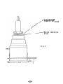
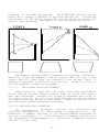
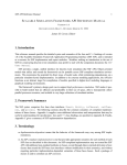
1
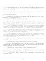
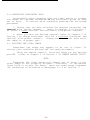
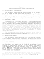
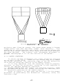
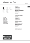
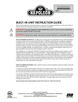
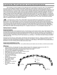
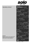
SECTION III - OPERATION
GENERAL INFORMATION
Chapter 1
1.1 FACTORY PRESET MODE OF OPERATION
The Aquastar 600 comes
following manner:
from the factory preset in the
1.1.1 PICTURE SIZE AND THROW DISTANCE
The Aquastar 600 leaves the factory properly set-up for an
on-axis 60" X 80" image with a throw distance of 10' 2" from the
screen to the front of the green lens.
The Aquastar 600 is
capable of projecting an image from 4 to 12 feet wide with the
high resolution lenses. Optional lenses can give the capability
for a picture width of up to 25 feet. If an image size of other
than 60" X 80" is desired, it will be necessary to change the
throw distance, change the lateral lens adjustments, and refocus
the lenses.
These adjustments should be performed by the
qualified technician doing the projector installation.
The projector comes preset for FRONT PROJECTION but has the
capability of operating in either front or rear screen modes. To
reverse the direction of the horizontal sweep, a sweep reversal
plug (J-21) is provided on the deflection board. When the sweep
is reversed switch S-501 must be changed to the "ON" position for
the remote control to center properly.
The magnetic and electronic effects of sweep reversal will require some mechanical and
electronic realignments so this procedure should be performed
only by a qualified technician.
1.1.2 NTSC/RGB OPERATION
The projector comes preset for RGB operation on a 60" X 80"
screen. NTSC operation of any projector does not use the maximum
viewing area possible within the transmission facility and the
Aquastar 600 is no exception.
The sides and the top of the
raster are blanked and this portion of the picture is not seen by
the viewer. However, in RGB operation, the maximum viewing area
is all used. There will be a slight reduction in picture size
for NTSC operation.
1.1.3 ON/OFF AXIS PROJECTION
The projector is preset for ON AXIS PROJECTION. This means
that the projector is mounted perpendicular to the center of the
Projection at any angle other than perpendicular will
screen.
The
introduce keystone distortion into the projected image.
Aquastar 600 can correct for keystone distortion at projection
angles of up to 15 degrees, but a qualified technician should
make this correction adjustment.
-38-
1.1.4 HORIZONTAL AND VERTICAL HOLD PRESET CHANNELS
The NTSC channel and each of the eight RGB horizontal and
vertical hold preset channels are set at the factory for 15,750Hz
for horizontal and 60Hz for vertical. To change the preset hold
rates, refer to Chapter 3 of Section I.
-39-
Chapter 2
SYSTEM INFORMATION
2.1 SYSTEM OPERATION
The following section contains simple step by step instructions for turning the projector ON and OFF and aligning and
adjusting the video image.
2.1.1 SYSTEM TURN ON
Verify that the power cord to the projection unit is firmly
connected to an active AC outlet.
NOTE: All Aquastar 600's are shipped from the factory configured
for 115V 60Hz operation unless special ordered for 220v 50Hz
operation. Your unit will be marked adjacent to the power cord
on the projector rear panel with the required voltage.
1. Depress the ON button on the front of t h e remote control.
A. At this time the POWER ON LED on the remote control
should be lit.
B. The projector should start a 10 second countdown procedure. This countdown will be displayed on the projector LED.
-40-
C. Upon completion of the countdown procedure, the projector
In the event of a malfunction, error
will be ready for use.
codes will be displayed on the projector LED's by the error
diagnostic circuits.
D. Allow the projector to warm up for about 15 minutes
before proceding with the set-up adjustments.
2.1.2 SYSTEM TURN OFF
To turn the projector OFF depress the ON switch on the front
panel of the remote control.
2.1.3 COMPOSITE VIDEO CONNECTIONS: NTSC
This section of the manual describes how to adjust the
projector to obtain the best video image when using a composite
video input signal (NTSC). All adjustments should be made only
after the warm-up period described.
1. The brightness, picture, color, and tint controls may be
adjusted from the remote control for the desired projected image.
( Refer to Chapter 3 of Section 1 for remote control operation)
2. The detail (peaking), and focus may be adjusted for a
sharp, well defined projected image. ( Refer to Chapter 3 of
Section 1 for remote control operation)
3. The composite video (NTSC) should be connected to the
IN BNC connection on the back panel of the projector.
(The
feed-through BNC must be terminated if not in use)
VIDEO
2.1.4 RGB CONNECTIONS
There are three different cable connection configurations
from RGB signal sources.
1. Three wire - Red, Green, Blue, w/sync on green.
In this configuration only the Red, Green , and Blue BNC
connectors are used and the sync is extracted from the green
signal internally by the projector.
2. Four wire - Red, Green, Blue, Composite sync.
In this configuration The Red, Green, and Blue inputs are
connected as before and additionally a composite sync signal is
applied to the sync input BNC connector.
3. Five wire - Red, green, blue w/separate horizontal and
vertical syncs.
-41-
In this configuration the Red, Green, and Blue inputs are
connected as before and the horizontal sync is connected to the
sync BNC connector and the vertical sync is connected to the
vertical drive BNC connector.
The Aquastar 600 will automatically detect which
configuration is used and adapt to that input.
input
NOTE
DO NOT USE A SYNC INPUT CABLE IF THERE IS SYNC ON THE GREEN
SIGNAL. THIS CONFIGURATION WILL CAUSE A WASHED-OUT IMAGE.
2.2 VIDEO IMAGE ALIGNMENTS (DC positioning)
On rare occasions, the Red, Green, and Blue image components
may become misaligned.
This problem is indicated by a red,
green, or blue line along the edges of sharply defined objects in
the projected image. To correct this problem do the following:
DO NOT PERFORM THIS PROCEDURE UNTIL THE SYSTEM HAS HAD A 15
MINUTE WARM-UP TIME.
1. Using the remote control, project the crosshair test
pattern. (refer to Chapter 3 of Section 1 for remote control
operation).
2. If the Red and/or Blue crosshairs do not superimpose the
Green crosshair properly, perform step 3.
3. To correct a vertical or horizontal misalignment: Use the
Green crosshair as the reference and superimpose the Red and Blue
crosshairs on the Green crosshair. (refer to Red centering and
Blue centering in Chapter 3 of Section 1)
2.3 CORRECTING A VERTICAL IMAGE ROLL
Occasionally after changing from one video source to another
To correct this condition perform the
the image will roll.
following procedure.
1. Insure that you have selected the desired horizontal and
vertical hold preset channel. (refer to Chapter 3 of Section 1 to
select a given vertical and horizontal hold preset channel)
Refer to Chapter 3
2. After you have the desired channel:
of Section 1 to change vertical hold for a selected horizontal
and vertical hold preset channel. Change the vertical hold until
the rolling stops.
-42-
2.4 CORRECTING HORIZONTAL HOLD
Occasionally after changing from one video source to another
the image will become distorted in the horizontal plane or drop
To correct this condition perform the following
out of sync.
procedure:
1. Insure that you have selected the desired horizontal and
(refer to Chapter 3 of Section 1
to select a given vertical and horizontal hold preset channel)
vertical hold preset channel.
2. After you have the desired channel: Refer to Chapter 3 of
Section 1 to change horizontal hold for a selected horizontal and
vertical hold preset channel. Change the horizontal hold until
the image is in proper sync.
2.5 FOCUSING THE VIDEO IMAGE
Sometimes the image may appear to be out of focus. To
correct this condition perform the following procedure:
1. Using the remote control, focus the image for the desired
picture. (refer to Chapter 3 of Section 1 TO CHANGE MASTER FOCUS)
NOTE
Sometimes the video image will appear out of focus if the
Therefore, if the master
video image is not properly aligned.
focus fails to correct the image, check the video image alignment
(DC centering) as discussed in paragraph 3.1.2 of Section 1.
-43-
Chapter 3
SYSTEM TROUBLESHOOTING
This chapter of the manual describes the steps for correcting difficulties that may be encountered when using this projection system. If you should encounter a problem, locate it in the
text below and follow the steps outlined for its correction. If
you are still unable to correct the problem, troubleshoot the
projector using the theory of operation section and the schematic
diagrams.
3.1 SYSTEM WILL NOT OPERATE
1..
Verify that the power cord is firmly plugged in at both
ends.
2. Verify that power outlets are furnishing power.
3. With the power cord plugged in depress the ON button on
the front of the remote control. The LED on the remote control
should be lit at this time. If the LED on the remote is not lit,
check the master fuse F-l on the back panel of the projector. If
the fuse is not open, troubleshoot the AC distribution and
associated cables.
The +5 V supply for the microprocessor
furnishes the power to light the remote LED.
4. If the LED on the remote is lit after depressing the ON
button on the remote:
a. Check the LED readout on the projector for error codes
and if error codes are present, refer to Figure 4-4 to determine
where the problem is.
b. If no error codes are displayed on the projector LED
check your video source. With no video source there will be no
projected image. (no raster is projected in normal operation,
only video data)
c. After insuring that the video source is proper and you
are in the proper mode of operation for that source, if you still
have a problem troubleshoot the video section of the projector.
3.2 SYSTEM STOPS DURING OPERATION
One of the projector's protection circuits may have been
tripped by a power surge or an arc. To reset the protect circuit
perform the following procedure:
1. Depress the ON button on the remote control to turn the
projector OFF.
2. Wait 1 minute to allow the protect circuit to reset.
-44-
3. Depress the ON button on the remote control to turn the
projector on.
4. If the image still does not appear, follow the procedures
outlined under "System will not operate".
-45-
Chapter 4
CHANGING FROM FACTORY PRESET CONFIGURATION
4.1 FACTORY PRESET CONFIGURATION
The projector comes from the factory preset for an on-axis,
60" by 80" image (in RGB) using front projection.
The Aquastar 600 is capable of projecting images from 4 to
25 feet in width, front or rear screen projection, floor, table,
or ceiling mounting, etc.
This chapter of the manual will try to explain the steps
necessary to change from one configuration to another.
4.2 PERFORMANCE CHECK
This portion of the chapter describes a complete performance
check of the projector.
It also provides a reference to direct
you to adjustment and alignment procedures contained in Section V
of this manual. The following performance check is not essential
for installation of new projectors, installed the same as the
preset configuration, since the factory has preset all the
If the installation requirements differ from the
controls.
factory standards, as outlined above, adjustment of the projector
is required. If the projector is older or used often as a demo
unit, periodic performance checks are recommended to insure
optimum performance.
The procedures discussed below are presented in the order in
which they should be performed. The step-by-step procedures are
all contained in Section V of this manual.
4.3 MECHANICAL ALIGNMENT
The performance check is divided into two sections, mechanical alignments and electronic alignments. The mechanical portion
needs to be done first to reduce the amount of electronic correction.
4.3.1 LENS FOCUSING
Changing image size changes the focal plane of the projector
Lens
and the image, will appear out of focus on the screen.
focusing is explained in section V of this manual. The lateral
lens adjustment will also be required. refer to paragraph 4.3.2
below. For image sizes from 4 to 6 feet in width, optical wedges
For image sizes above 12 feet in width wide
may be required.
screen lenses will be required.
4.3.2 LATERAL LENS ADJUSTMENT
This adjustment is needed whenever image size is changed.
The figure on the next page shows the effect of moving the
projector closer or further from the screen. When moving the
-46-
FIG I
t
AGUAS'PAR
9’
for
moved t o
image
befor e acree n BIZC
caangr
(Screen
1nc; cCcplctcd
4 x 6’
h e r e i rt h e t3OSSdAIit.)
projector away from the screen, the green image seems to become
This
larger while the Red and Blue images move laterally.
condition is called parallax and can be corrected by moving the
Red and Blue lenses laterally after image size and throw distance
The lateral lens adjustment procedure is
has been decided.
provide idn Paragraph 4.3.2 of this section of the manual.
4.3.3 RASTER CENTERING
To obtain optimum performance the raster should be centered
on the face of the CRT's. There are two things that will change
the raster centering, the centering rings on the CRT deflection
coils and the centering controls on the Remote control.
It is very important that the centering rings be properly
so that the electronic centering is not required to
adjusted
correct for improper mechanical centering.
Always insure that the images are centered properly, WITH
THE REGISTRATION SWITCH OFF, before correcting the centering with
the electronic centering on the remote control.
Refer to Figure 2 on next page and Section V for the proper
procedure on performing the mechanical centering using the
centering rings.
-47-
ASTIGMATISH
CORRECTION R!NGS
RASTER CENTERING
RINGS
FIG.2
-48-
With the raster centered on the face of the CRT's, as the
projector is moved forward or backward the three projected images
will diverge. When this happens it is necessary to realign the
If you are unable to
images with the lateral lens adjustments.
properly overlay the images upon each other it will be necessary
to perform an alignment. Refer to Section V for the mechanical
and electronic alignment procedures.
4.3.4
FRONT AND REAR PROJECTION (sweep reversal)
Changing from front to rear projection or vice versa involves reversing the direction of the horizontal sweep action.
This is accomplished by removing and turning around a sweep
reversal plug on the deflection board. (See drawing below)
WARNING
Be sure to turn the projector OFF and disconnect power from the
projector before reversing the sweep reversal plug (J-21).
Failure to do so may result in electrical shock and severe damage
to the projector.
-49-
When the horizontal sweep is reversed a number of things
occur. Deflection currents and magnetic fields are reversed so
that the projected image is correct. The raster centering should
not move when the sweep is reversed. If the sweep does move it
will be necessary to adjust R-131. The procedure for adjusting
R-131 can be found in Section V.
When the sweep is reversed it may be necessary to register
the projector. The procedure for registering the projector can
be found in Section V.
4.3.5 REGISTRATION ADJUSTMENTS
The registration adjustments are accessible from the back
This portion of the manual will discuss
panel (see figure 3).
ON/OFF AXIS projection, the function of the individual focus
controls and certain considerations before performing the registration procedure.
JORK
LIGHT
pILL--‘E3 i
p%!sgqpqq
_.
@0
rzpyp
I __-
4
C
(0
@)
6
4.3.5.1.
VERTICAL SIZE
VERTICAL LIN o
HORIZONTAL S K E W
tiO;~I7Of4-i-~~~ P@‘$!:
E - W KEYSTUNE
k&YSTCNE
_
~~6
_
-LIGHT
___I
8
---
G HORIZONTAL LIN.
VERTICAL SKEW
I VERTJCAL BOW
\‘;:uT ti
FIG. 3 -5
ON AXIS PROJECTION
An example of ON-AXIS projection is shown in figure 4, as
you can see, the projector is mounted perpendicular or ON-AXIS
This arrangement may be
to the center of the screen.
Figure 5 a and b shows
inconvenient in most installations.
alternate methods of
-50-
With OFF-AXIS projection the
mounting, or off-AXIS projection.
raster will contain a measure of keystone distortion. Increasing
the degree of OFF-AXIS projection either above or below the
On-Axis line increases the amount of this keystone distortion.
FIGURE Sl:
El
The Aquastar 600 provides 15 degrees of keystone correction.
r 600 no higher than the top of the
Generally, keep the Aquastar
screen and no lower than the bottom of the screen, then 15
degrees of keystone correction is sufficient. Refer to Section V
for the keystone correction procedure.
4.3.5.2.
INDIVIDUAL FOCUS ADJUSTMENTS
These controls, under the top cover, are used with master
focus control on the remote control box, to focus the image.
Once the individual controls are properly adjusted the focus of
all three guns can be controlled simultaneously from the remote
to correct for any drift in the focus. Refer to Section V for
the Individual Focus Adjustment procedure.
4.3.5.3 REGISTRATION PROCEDURE
The registration procedure involves the mechanical and
electronic alignment of all three images to converge as one. The
mechanical alignment involves all of the procedures discussed in
The electronic alignment begins with
Section V paragraph 3.1.
the adjustments in paragraphs 3.2. Electronic alignment controls
(figure 3-5) are used.
-51-
BEFORE THE FINAL ELECTRONIC ADJUSTMENTS ARE MADE YOU
MUST INSURE THAT THE REGISTRATION SWITCH IS
- OFF
- AND:
1.
The rasters are centered in all CRT's.
2.
Each of the images are focused.
3.
The centers of all three crosshairs are superimposed on one another. This is accomplished
with the raster centering procedure and the
Lateral Lens Adjustment.
4.
The differences in the yokes both horizontally
(horizontal and
and vertically have been matched.
vertical size)
5.
Master vertical linearity is adjusted properly.
Providing these conditions have been met you are ready
to begin the final alignment. Refer to Section V for the
registration adjustments.
4.3.6.
OPERATING
INST R UC T IONS
(RGB
MODE )
RGB operation in the Aquastar 600 is different from NTSC
operation only in how video information is processed. Instead of
a single composite video signal for NTSC operation, RGB requires
separate Red, Green and Blue signals and, in some cases, a
These RGB signals are supplied by some
separate SYNC signal.
computers graphics generators and video cameras. They are each
connected to the Aquastar 600 back panel, processed separately
and projected simultaneously to reproduce a full color range.
CONNECTIONS AND ADJUSTMENTS FOR RGB REMONSTRATIONS - There
are three different modes of operation in the RGB mode:
1.
2.
3.
1.
2.
Perform the Alignment procedure using the internal test
pattern.
Connect the sync wire/wires to the back panel.
*
*
*
3.
Red, Green and Blue video with sync on Green (3 wire).
Red, Green and Blue video with external composite sync
(4 wire).
Red, Green and Blue video with separate horizontal and
vertical sync (5 wire).
Green video for a 3 wire system
Composite sync to the sync input for a 4 wire system
Horizontal sync to the sync input, vertical sync to
the vertical drive input for a 5 wire system.
Remove the two lower rear cover brackets.
-52-
3.
4.
5.
Remove the two lower rear cover brackets.
Remove the two upper back panel retaining screws.
Pull down the back panel, exposing the video PCB.
4.3.7.
RASTER CENTERING
Figure 6 illustrates the effect of decreasing the blanking
time for RGB operation. The image on the CRT is wider, taller
and off--center compared to a typical NTSC raster.
WARNING
Overscanning the CRT's can cause severe
damage to the CRT's and the high voltage
power supply.
--_---
FIGURE 6
Section V, paragraph 2.1 for the RGB blanking and
raster centering procedures.
Go the
4.3.8.
GRAYSCALE TRACKING ADJUSTMENTS
Using the Aquastar 600 in the RGB mode will require the
installer or technician to adjust the RGB gain and sub-brightness
controls to obtain grayscale tracking. ESP cannot adjust the RGB
video controls because the RGB signal sources differ in strength
between manufacturers. The procedure is provided in Section V.
The projector has been adjusted with 1 Vp-p RGB signals for
proper grayscale tracking.
-53-
4.3.9.
RGB SYSTEM OPERATION
The NTSC and RGB operation of the Aquastar 600 is identical
except for the items discussed above. All procedures described
in Section V with the exception of raster size and centering
changes, apply also to NTSC operation. On the remote control the
BRITEness control is the only picture control useable in the RGB
mode.
-54-