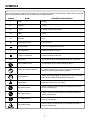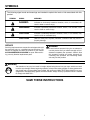
1
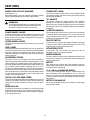
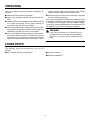
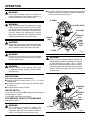
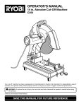
OPERATOR'S MANUAL
14 in. ABRASIVE
CUT-OFF MACHINE
CM1450
Your new cut-off machine has been engineered and manufactured to our high standards for dependability, ease of operation, and operator safety. When properly cared for, it will give you years of rugged, trouble-free performance.
WARNING:
To reduce the risk of injury, the user must read and understand the operator’s manual before using this product.
Thank you for buying a RIDGID product.
SAVE THIS MANUAL FOR FUTURE REFERENCE
TABLE OF CONTENTS
n Introduction ...................................................................................................................................................................... 2
n General Safety Rules .....................................................................................................................................................3-4
n Specific Safety Rules.....................................................................................................................................................4-5
n Symbols.........................................................................................................................................................................6-7
n Electrical ........................................................................................................................................................................... 8
n Features .......................................................................................................................................................................8-10
n Unpacking ..................................................................................................................................................................... 11
n Loose Parts..................................................................................................................................................................... 11
n Operation ...................................................................................................................................................................12-14
n Adjustments...............................................................................................................................................................15-17
n Maintenance ................................................................................................................................................................... 18
n Troubleshooting .............................................................................................................................................................. 19
n Warranty ......................................................................................................................................................................... 21
n Parts Ordering/Service ................................................................................................................................................... 22
INTRODUCTION
Your cut-off machine has many features for making the use of this product more pleasant and enjoyable. Safety, performance,
and dependability have been given top priority in the design of this product making it easy to maintain and operate.
IMPORTANT INFORMATION ON THE USE OF CUT-OFF WHEELS AND ANSI B7.1 can be obtained by writing to:
GRINDING WHEEL INSTITUTE
30200 Detroit Road
Cleveland, OH 44145-1967
2
GENERAL SAFETY RULES
n ALWAYS WEAR SAFETY GLASSES WITH SIDE
SHIELDS. Everyday eyeglasses have only impactresistant lenses; they are NOT safety glasses.
n SECURE WORK. Use clamps or a vise to hold work
when practical. It's safer than using your hand and
frees both hands to operate tool.
n DON'T OVERREACH. Keep proper footing and balance
at all times.
n MAINTAIN TOOLS WITH CARE. Keep tools
sharp and clean for better and safer performance.
Follow instructions for lubricating and changing
accessories.
n DISCONNECT TOOLS. When not in use, before
servicing, or when changing attachments, wheels,
bits, cutters, etc., all tools should be disconnected.
n AVOID ACCIDENTAL STARTING. Be sure switch is
off when plugging in.
n USE RECOMMENDED ACCESSORIES. The use of
improper accessories may cause risk of injury.
n NEVER STAND ON TOOL. Serious injury could occur if
the tool is tipped or if the cutting wheel is unintentionally
contacted.
n CHECK DAMAGED PARTS. Before further use of the
tool, a guard or other part that is damaged should
be carefully checked to determine that it will operate
properly and perform its intended function. Check for
alignment of moving parts, binding of moving parts,
breakage of parts, mounting and any other conditions
that may affect its operation. A guard or other part that
is damaged must be properly repaired or replaced by
an authorized service center to avoid risk of personal
injury.
n NEVER LEAVE TOOL RUNNING UNATTENDED.
TURN POWER OFF. Don't leave tool until it comes to
a complete stop.
n PROTECT YOUR LUNGS. Wear a face or dust mask
if the cutting operation is dusty.
n PROTECT YOUR HEARING. Wear hearing protection
during extended periods of operation.
n DON'T ABUSE CORD. Never yank cord to disconnect
from receptacle. Keep cord from heat, oil, and sharp
edges.
n USE OUTDOOR EXTENSION CORDS. When tool is
used outdoors, use only extension cords with approved
ground connection that are intended for use outdoors
and so marked.
n WHEELS COAST AFTER TURN OFF.
WARNING:
Read and understand all instructions. Failure to
follow all instructions listed below may result in
electric shock, fire and/or serious personal injury.
READ ALL INSTRUCTIONS
n KNOW YOUR POWER TOOL. Read the operator's
manual carefully. Learn the cut-off machine's
applications and limitations as well as the specific
potential hazards related to this tool.
n GUARD AGAINST ELECTRICAL SHOCK BY
PREVENTING BODY CONTACT WITH GROUNDED
SURFACES. For example; pipes, radiators, ranges,
refrigerator enclosures.
n KEEP GUARDS IN PLACE and in working order. Never
operate the tool with any guard or cover removed.
Make sure all guards are operating properly before
each use.
n REMOVE ADJUSTING KEYS AND WRENCHES.
Form habit of checking to see that keys and adjusting
wrenches are removed from tool before turning it on.
n KEEP WORK AREA CLEAN. Cluttered areas and
benches invite accidents. DO NOT leave tools or
material on the machine while it is in operation.
n AVOID DANGEROUS ENVIRONMENT. Don't use
power tools in damp or wet locations or expose to
rain. Keep work area well lit.
n KEEP CHILDREN AND VISITORS AWAY. All visitors
should wear safety glasses and be kept a safe distance
from work area. Do not let visitors contact tool or
extension cord while operating.
n MAKE WORKSHOP CHILDPROOF with padlocks or
master switches, or by removing starter keys.
n DON'T FORCE TOOL. It will do the job better and
safer at the feed rate for which it was designed.
n USE RIGHT TOOL. Don't force tool or attachment
to do a job it was not designed for. Don't use it for a
purpose not intended.
n MAKE SURE YOUR EXTENSION CORD IS IN GOOD
CONDITION. When using an extension cord, be sure
to use one heavy enough to carry the current your
product will draw. An undersized cord will cause a
drop in line voltage resulting in loss of power and
overheating. A wire gage size (A.W.G.) of at least 14
is recommended for an extension cord 25 feet or less
in length. If in doubt, use the next heavier gage. The
smaller the gage number, the heavier the cord.
n DRESS PROPERLY. Do not wear loose clothing, gloves,
neckties, or jewelry. They can get caught and draw you
into moving parts. Rubber gloves and nonskid footwear
are recommended when working outdoors. Also wear
protective hair covering to contain long hair.
3
GENERAL SAFETY RULES
n INSPECT EXTENSION CORDS PERIODICALLY and
replace if damaged.
n KEEP TOOL DRY, CLEAN, AND FREE FROM OIL AND
GREASE. Always use a clean cloth when cleaning.
Never use brake fluids, gasoline, petroleum-based
products, or any solvents to clean tool.
n STAY ALERT AND EXERCISE CONTROL. Watch what
you are doing and use common sense. Do not operate
tool when you are tired. Do not rush.
n DO NOT USE TOOL IF SWITCH DOES NOT TURN
IT ON AND OFF. Have defective switches replaced by
an authorized service center.
n NEVER USE IN AN EXPLOSIVE ATMOSPHERE.
Normal sparking of the motor could ignite fumes.
n INSPECT TOOL CORDS PERIODICALLY. If damaged,
have repaired by a qualified service technician at an
authorized service facility. The conductor with insulation
having an outer surface that is green with or without
yellow stripes is the equipment-grounding conductor.
If repair or replacement of the electric cord or plug is
necessary, do not connect the equipment-grounding
conductor to a live terminal. Repair or replace a
damaged or worn cord immediately. Stay constantly
aware of cord location and keep it well away from the
rotating wheel.
SPECIFIC SAFETY RULES
n USE ONLY CORRECT WHEELS. Do not use wheels with
incorrect size holes. Never use wheel washers or wheel
screws that are defective or incorrect. The maximum wheel
capacity of your cut-off machine is 14 in. (356 mm).
n DO NOT REMOVE THE MACHINE'S WHEEL GUARDS.
Never operate the machine with any guard or cover
removed. Make sure all guards are operating properly
before each use.
n KEEP HANDS AWAY FROM CUTTING AREA. Keep
hands away from wheel. Do not reach underneath work
or around or under the wheel while the wheel is rotating.
Do not attempt to remove cut material while wheel is
moving.
n ALWAYS SUPPORT LONG MATERIAL. To minimize risk
of tipping machine, always support long material.
n BEFORE MAKING A CUT, BE SURE ALL ADJUSTMENTS ARE SECURE.
n ALWAYS USE THE VISE CLAMP to secure the
material.
n NEVER TOUCH WHEEL or other moving parts during
use.
n NEVER START THE CUT-OFF MACHINE WHEN THE
WHEEL IS IN CONTACT WITH THE MATERIAL.
n NEVER cut more than one piece of material at a time.
DO NOT STACK more than one piece of material on the
machine base at a time.
n NEVER PERFORM ANY OPERATION "FREEHAND".
Always secure the material to be cut in the vise.
n NEVER hand hold a piece of material. Material will become
very hot while being cut.
n NEVER reach behind, under, or within three inches of the
wheel and its cutting path with your hands and fingers
for any reason.
n NEVER reach to pick up a piece of material, a piece of
scrap, or anything else that is in or near the cutting path
of the wheel.
n AVOID AWKWARD OPERATIONS AND HAND
POSITIONS where a sudden slip could cause your hand
n
n
n
n
n
n
n
n
n
n
4
to move into the wheel. ALWAYS make sure you have
good balance.
NEVER stand or have any part of your body in line with
the path of the wheel.
ALWAYS release the power switch and allow the wheel
to stop rotating before raising wheel guard or removing
material.
DO NOT TURN THE MOTOR SWITCH ON AND OFF
RAPIDLY. This could cause the wheel to loosen and could
create a hazard. Should this ever occur, stand clear and
allow the wheel to come to a complete stop. Disconnect
your cut-off machine from the power supply and securely
retighten the wheel arbor bolt after checking the wheel
for damage.
WHEN SERVICING USE ONLY IDENTICAL RIDGID
REPLACEMENT PARTS. Use of any other parts may
create a hazard or cause product damage.
NEVER leave the cut-off machine unattended while
connected to a power source.
IF ANY PART OF THIS CUT-OFF MACHINE IS MISSING
or should break, bend, or fail in any way, or should any
electrical component fail to perform properly, shut off
the power switch, remove the machine plug from the
power source and have damaged, missing, or failed parts
replaced before resuming operation.
MAKE SURE THE CUT-OFF WHEEL IS SECURELY
MOUNTED as described in the operating instructions
before connecting the tool to a power supply. Do not
tighten wheel excessively, since this can cause cracks.
CHECK THE WHEEL FOR FISSURES AND CRACKS,
and test for normal operation prior to use.
ONLY USE A CUT-OFF WHEEL RATED FOR 3900
RPM OR GREATER and manufactured in compliance
with ANSI B7.1. Always store wheels in a dry place with
little temperature variation.
ALWAYS EASE THE ABRASIVE WHEEL AGAINST THE
MATERIAL when starting to cut. A harsh impact can break
the wheel.
SPECIFIC SAFETY RULES
n ALWAYS STAY ALERT! Do not allow familiarity (gained
from frequent use of your cut-off machine) to cause a
careless mistake. ALWAYS REMEMBER that a careless
fraction of a second is sufficient to inflict severe injury.
n STAY ALERT AND EXERCISE CONTROL. Watch what
you are doing and use common sense. Do not operate
tool when you are tired. Do not rush.
n SAVE THESE INSTRUCTIONS. Refer to them frequently
and use them to instruct other users. If you loan someone
this tool, loan them these instructions also.
n BEFORE CUTTING press the trigger switch and allow
the cut-off wheel to reach full speed.
n MAKE SURE THE WORK AREA HAS AMPLE LIGHTING
to see the work and that no obstructions will interfere with
safe operation BEFORE performing any work using your
cut-off machine.
n DO NOT OPERATE THIS TOOL WHILE UNDER
THE INFLUENCE OF DRUGS, ALCOHOL, OR ANY
MEDICATION.
WARNING:
Some dust created by power sanding, sawing, grinding, drilling, and other construction activities contains chemicals
known to cause cancer, birth defects or other reproductive harm. Some examples of these chemicals are:
• lead from lead-based paints,
• crystalline silica from bricks and cement and other masonry products, and
• arsenic and chromium from chemically-treated lumber.
Your risk from these exposures varies, depending on how often you do this type of work. To reduce your exposure
to these chemicals: work in a well ventilated area, and work with approved safety equipment, such as those dust
masks that are specially designed to filter out microscopic particles.
5
SYMBOLS
Some of the following symbols may be used on this tool. Please study them and learn their meaning. Proper interpretation of these symbols will allow you to operate the tool better and safer.
SYMBOL
NAME
DESIGNATION/EXPLANATION
V
Volts
Voltage
A
Amperes
Current
Hz
W
min
no
.../min
Hertz
Frequency (cycles per second)
Watt
Power
Minutes
Time
Alternating Current
Type of current
Direct Current
Type or a characteristic of current
No Load Speed
Rotational speed, at no load
Class II Construction
Double-insulated construction
Per Minute
Revolutions, strokes, surface speed, orbits etc., per minute
Wet Conditions Alert
Do not expose to rain or use in damp locations.
Read The Operator’s Manual
To reduce the risk of injury, user must read and understand
operator’s manual before using this product.
Eye Protection
Always wear safety goggles or safety glasses with side shields
and a full face shield when operating this product.
Safety Alert
Precautions that involve your safety.
No Hands Symbol
Failure to keep your hands away from the blade will result in
serious personal injury.
No Hands Symbol
Failure to keep your hands away from the blade will result in
serious personal injury.
No Hands Symbol
Failure to keep your hands away from the blade will result in
serious personal injury.
No Hands Symbol
Failure to keep your hands away from the blade will result in
serious personal injury.
6
SYMBOLS
The following signal words and meanings are intended to explain the levels of risk associated with this
product.
SYMBOL
SIGNAL
MEANING
DANGER:
Indicates an imminently hazardous situation, which, if not avoided, will
result in death or serious injury.
WARNING:
Indicates a potentially hazardous situation, which, if not avoided, could
result in death or serious injury.
CAUTION:
Indicates a potentially hazardous situation, which, if not avoided, may
result in minor or moderate injury.
CAUTION:
(Without Safety Alert Symbol) Indicates a situation that may result in
property damage.
SERVICE
WARNING:
Servicing requires extreme care and knowledge and should
be performed only by a qualified service technician. For
service we suggest you return the product to your nearest
AUTHORIZED SERVICE CENTER for repair. When servicing, use only identical replacement parts.
To avoid serious personal injury, do not attempt to
use this product until you read thoroughly and understand completely the operator’s manual. Save
this operator’s manual and review frequently for
continuing safe operation and instructing others
who may use this product.
WARNING:
The operation of any tool can result in foreign objects being thrown into your eyes, which can result
in severe eye damage. Before beginning operation, always wear safety goggles or safety glasses with
side shields and a full face shield when needed. We recommend Wide Vision Safety Mask for use over
eyeglasses or standard safety glasses with side shields. Always wear eye protection which is marked
to comply with ANSI Z87.1.
SAVE THESE INSTRUCTIONS
7
ELECTRICAL
EXTENSION CORDS
GROUNDING INSTRUCTIONS
Use only 3-wire extension cords that have 3-prong grounding plugs and 3-pole receptacles that accept the tool's plug.
When using a power tool at a considerable distance from the
power source, use an extension cord heavy enough to carry
the current that the tool will draw. An undersized extension
cord will cause a drop in line voltage, resulting in a loss of
power and causing the motor to overheat. Use the chart
provided below to determine the minimum wire size required
in an extension cord. Only round jacketed cords listed by
Underwriter's Laboratories (UL) should be used.
Length of Extension Cord
Wire Size (A.W.G.)
Up to 25 feet
14
26-50 feet
12
When working with the tool outdoors, use an extension cord
that is designed for outside use. This is indicated by the letters WA on the cord's jacket.
Before using an extension cord, inspect it for loose or exposed wires and cut or worn insulation.
In the event of a malfunction or breakdown, grounding provides a path of least resistance for electric current to reduce
the risk of electric shock. This tool is equipped with an electric cord having an equipment-grounding conductor and a
grounding plug. The plug must be plugged into a matching
outlet that is properly installed and grounded in accordance
with all local codes and ordinances.
Do not modify the plug provided. If it will not fit the outlet, have
the proper outlet installed by a qualified electrician. Improper
connection of the equipment-grounding conductor can result
in a risk of electric shock. The conductor with insulation having
an outer surface that is green with or without yellow stripes is
the equipment-grounding conductor. If repair or replacement
of the electric cord or plug is necessary, do not connect the
equipment-grounding conductor to a live terminal.
Check with a qualified electrician or service personnel if the
grounding instructions are not completely understood, or if
in doubt as to whether the tool is properly grounded.
Repair or replace a damaged or worn cord immediately.
This tool is intended for use on a circuit that has an outlet
like the one shown in Figure 1. It also has a grounding pin
like the one shown.
CAUTION:
Keep the cord away from the cutting area and
position the cord so that it will not be caught on
material, tools, or other objects during cutting.
ELECTRICAL CONNECTION
Your Cut-Off Machine is powered by a precision built electric motor. It should be connected to a power supply that
is 120 volts, 60 Hz, AC only (normal household current).
Do not operate this tool on direct current (DC). A substantial
voltage drop will cause a loss of power and the motor will
overheat. If the machine does not operate when plugged
into an outlet, double check the power supply.
POWER SUPPLY
Before operating your cut-off machine, check your power
supply and make sure it meets the requirements listed on
the tool’s data plate. A substantial voltage drop will cause
a loss of power and machine overheating.
Common causes of power loss and machine overheating are insufficient extension cord size and multiple tools
operating from the same power source.
GROUNDING
PIN
COVER OF GROUNDED
OUTLET BOX
Fig. 1
8
FEATURES
PRODUCT SPECIFICATIONS
n
n
n
n
n
Input......................... 120V, 60 Hz, AC Only,15 Amperes
No Load Speed...............................................3900/min.
Arbor Diameter ....................................... 1 in. (25.4 mm)
Wheel Diameter ..................................... 14 in. (356 mm)
Net Weight ............................................... 51 lbs. (23 kg)
n Fence Angle......................................Right (45˚), Left (0˚)
n Vise Clamp Angle ...........................Right (45˚), Left (45˚)
n Maximum Cutting Capacities:
Round Pipe .................. 5 in. (127 mm) outside diameter
Steel Studs ................................................... Full Bundle
Bar Stock ................................................ 2 in. (50.8 mm)
"D" HANDLE
MOTOR
UPPER WHEEL GUARD
BRUSH CAP
SPINDLE LOCK
LOWER WHEEL GUARD
ADJUSTABLE STOP
MITER LOCK HANDLE
14 in. (356 mm) ABRASIVE WHEEL
ADJUSTABLE FENCE
VISE CLAMP
QUICK LOCKRELEASE LEVER
VISE CRANK HANDLE
RUBBER FEET
TRANSPORT CHAIN
Fig. 2
ARBOR
WRENCH
UPPER WHEEL
GUARD
"D" HANDLE
ON/OFF SWITCH
RUBBER
FEET (3)
PADLOCK
MACHINE
BASE
METAL
FOOT
WRENCH STORAGE
CARRYING
HANDLE
Fig. 3
9
Fig. 4
FEATURES
KNOW YOUR CUT-OFF MACHINE
TRANSPORT CHAIN
See Figures 2 - 4.
Before attempting to use your machine, familiarize yourself
with all operating features and safety requirements.
The cut-off machine can be locked in the lowered position
for compact storage. The chain is only used during carrying
and storage operations.
"D" HANDLE
The handle contains the trigger switch with a padlock
locking hole to prevent unauthorized use. The wheel is
lowered into the material by pushing down on the handle.
The wheel will return to its upright position when the handle
is released.
WARNING:
Do not allow familiarity with your machine to make
you careless. Remember that a careless fraction of
a second is sufficient to inflict severe injury.
CARRYING HANDLE
LOWER WHEEL GUARD
This handle is built into the unit to move it from one location
to another. Before attempting to pick up the unit by the
carrying handle always lock the power head in the down
position using the transport chain.
The lower wheel guard provides protection from each side
of the wheel. Contact with the material causes the lower
guard to raise over the upper wheel guard as the wheel is
lowered into the material.
ON/OFF SWITCH
UPPER WHEEL GUARD
To start the tool, squeeze the trigger. Release the trigger
to stop the tool. Install a padlock through the hole in the
trigger to help prevent unauthorized use.
Protects user from abrasive wheel contact on upper portion
of wheel.
VISE CLAMP
ADJUSTABLE STOP
A vise clamp has been provided with your cut-off machine. It
is located on the end of the vise screw and provides greater
control by clamping the material to the fence. It also prevents the material from creeping toward the wheel during a
cutting operation.
In the down (full cut) position, the pivot arm hits an
adjustable stop on the support bracket.
ARBOR WRENCH
The arbor wrench is found on the underside of the base. Use
wrench when replacing cut-off wheel or when making fence
angular adjustments.
ADJUSTABLE FENCE
The fence on your cut-off machine has been provided to
support the material and provide clamping support to the
vise for holding your material securely when making all cuts.
It is an adjustable fence that has been provided to make your
cut-off machine more versatile. It adjusts from 0° to 45° to
the right for making angled cuts. The hole pattern allows it
to be moved forward when making cuts in tall or thick stock,
such as square stock or tube stock. The hole pattern allows
it to be moved back when making cuts in stock that is thin
or wide, such as angle stock.
MOTOR
This machine has a strong motor with sufficient power to
handle tough cutting jobs. It also has externally accessible
brushes for ease of servicing.
14 in. (356 mm) ABRASIVE WHEEL
A 14 in. (356 mm) abrasive wheel is included with your
cut-off machine. It will cut materials up to 5 in. (127 mm)
thick or 8 in. (203 mm) wide, depending upon the thickness
or width of the material and the setting at which the cut is
being made.
QUICK LOCK-RELEASE LEVER
A quick lock-release lever has been provided on your cut-off
machine. This feature allows you to open and close the vise
clamp quickly without repetitive turning of the vise crank
handle.
MITER LOCK HANDLE
Allows the adjustable fence to be pivoted at a given angle
then locked in place.
SPINDLE LOCK
A spindle lock has been provided for locking the spindle
which keeps the wheel in your machine from rotating. Depress and hold the spindle lock while installing, changing,
or removing wheel only.
10
UNPACKING
Your cut-off machine has been shipped completely assembled.
pressure should remain on the machine arm to prevent
sudden rise upon release of the transport chain.
n Remove all loose parts from the carton.
n Examine all parts to make sure no breakage or damage
has occurred during shipping.
n Remove the packing materials from around your machine.
If any parts are damaged or missing, do not attempt to plug
in the power cord and turn the switch on until the damaged
or missing parts are obtained and are installed correctly.
Contact your nearest RIDGID dealer or call 1-866-539-1710
for assistance if any parts are missing or damaged.
n Carefully lift the cut-off machine from the carton and place
it on a level work surface. This is a heavy machine. To
avoid back injury, get help when needed.
n Do not discard the packing materials until you have carefully inspected the machine, identified all loose parts, and
satisfactorily operated your new cut-off machine.
WARNING:
If any parts are missing do not operate your cutoff machine until the missing parts are replaced.
Failure to do so could result in possible serious
injury.
n Your cut-off machine has been shipped with the machine
arm locked in the down position. To release the arm, push
down on top of the machine arm and remove transport
chain from bottom of motor housing. See Figure 2. Hand
LOOSE PARTS
The following items are included with your Cut-Off
Machine:
n Arbor Wrench, (Stored under Machine)
n Operator's Manual
n Warranty Registration
11
OPERATION
n To prevent machine movement or tipping during cutting
operation, secure cut-off machine in place to a workbench
or work surface that is also secure.
WARNING:
Do not allow familiarity with tools to make you
careless. Remember that a careless fraction of a
second is sufficient to inflict severe injury.
"D" HANDLE
WARNING:
ON/OFF SWITCH
This cut-off machine has been designed for cutting
metals, using reinforced abrasive cut-off wheels
only. Do not remove the wheel, install a steel blade,
and attempt to cut other types of materials such
as wood, masonry, etc. Attempting to cut these
other types of materials could cause an accident
resulting in possible serious personal injury.
VISE CLAMP
MATERIAL TO
BE CUT
MACHINE
BASE
QUICK
LOCKRELEASE
LEVER
WARNING:
Always wear safety goggles or safety glasses with side
shields during power tool operation or when blowing
dust. If operation is dusty, also wear a dust mask.
C-CLAMP
Fig. 5
WARNING:
Always use the vise clamp on the cut-off machine
to prevent accidents that could result in possible
serious personal injury.
WARNING:
Large, circular, or irregularly shaped material may
require additional means of clamping to be secured
in place adequately for cutting. Use “C” clamps
that can be mounted along the left and front side of
the machine base. Also use blocks to hold material
securely. Failure to comply could result in serious
personal injury.
WARNING:
Failure to unplug cut-off machine could result
in accidental starting causing possible serious
personal injury.
APPLICATIONS
(Use only for the purposes listed below)
n Cutting all types of metals such as 2 in. x 6 in. steel
framing studs.
n Cutting hard metal iron stock such as square bar stock
and angle iron.
n Cutting metal tube and pipe stock.
ADJUSTABLE
FENCE
ON/OFF SWITCH
To turn your cut-off machine ON, squeeze the on/off switch
located in the "D" handle.
To turn it OFF, release the on/off switch.
MATERIAL TO
BE CUT
VISE
CLAMP
CUTTING WITH YOUR CUT-OFF MACHINE
See Figures 5 and 6.
WARNING:
C-CLAMP
Do not attempt to cut wood or masonry with
this cut-off machine. Never cut magnesium or
magnesium alloy with this machine. Failure to
comply could result in serious personal injury.
C-CLAMP AREA
12
Fig. 6
OPERATION
CUT-OFF
obtain a uniform cut through the material. Never force the
wheel into the material being cut.
n When the cut is complete, release the on/off switch and
allow the wheel to stop rotating before raising the wheel
out of material.
See Figures 7 and 8.
A cut-off is made by cutting across the width of the material.
A straight crosscut is made with the adjustable fence set at
the zero degree position. Angled cut-offs are made with the
adjustable fence set at some angle other than zero.
TO CUT WITH YOUR CUT-OFF MACHINE:
WARNING:
n Firmly secure the material to be cut using the machine’s
vise (adjustable fence and vise clamp).
n loosen the miter lock handle securing the fence. See
Figures 7 and 8.
n Rotate the adjustable fence to the desired angle.
n Retighten miter lock handle securing fence.
Do not touch the cut material until it cools or you
can be burned. Failure to heed this warning could
result in serious personal injury.
"D" HANDLE
WARNING:
ON/OFF SWITCH
To avoid serious personal injury, always tighten
vise adjustment bolt securely before making a cut.
Failure to do so could result in movement of the
material while making a cut.
MITER
LOCK
HANDLE
n Place the material flat on the machine base with one
surface securely against the adjustable fence.
n Align cutting line on the material with the edge of the
abrasive wheel.
n Push in the vise crank handle to set the vise clamp against
the material. Turn the vise crank handle 1/2 to 1 turn
clockwise to securely clamp the material to the fence.
ADJUSTABLE
FENCE
MATERIAL TO
BE CUT
QUICK
LOCKRELEASE
LEVER
VISE
CRANK
HANDLE
WARNING:
MACHINE
BASE
To avoid serious personal injury, keep your hands
at least 3 in. (76.2 mm) from wheel.
Fig. 7
n When cutting long pieces, support the opposite end of
the material with a roller stand or with a work surface
level with the machine base.
WARNING:
Never perform any cutting operation freehand
(without placing material in the vise). Material will
get hot during cutting operation. Keep hands off of
metal being cut to avoid serious personal injury.
MITER
LOCK
HANDLE
MATERIAL
TO BE CUT
n Before turning on machine, perform a dry run of the
cutting operation just to make sure that no problems will
occur when the cut is made.
n Start the machine by grasping the handle and fully
squeezing the on/off switch. Allow several seconds for
the wheel to build up to full speed before letting it come
into contact with the material to be cut.
n Once it reaches full speed slowly lower the "D" handle
until the cut-off wheel comes in contact with the material
being cut. Continue to use steady and even pressure to
ADJUSTABLE
FENCE
VISE
CLAMP
VISE
CRANK
HANDLE
C-CLAMP
AREA
13
Fig. 8
OPERATION
TO USE THE QUICK LOCK-RELEASE LEVER
AND VISE CLAMP
To Loosen:
MITER
LOCK
HANDLE
VISE
CLAMP
ENGAGED
(TIGHTEN)
VISE
SCREW
See Figure 9.
WARNING:
NOT ENGAGED
(LOOSEN)
TO LOOSEN
Failure to unplug cut-off machine could result in
accidental starting causing possible serious personal injury.
n Unplug your cut-off machine.
n Release tension on the vise clamp by rotating the vise
crank handle 1/2 to 1 turn counterclockwise.
n Lift up the quick lock-release lever as shown in figure
9 and pull back on vise crank handle to slide open the
vise.
QUICK LOCK-RELEASE LEVER WITH
THREADS NOT ENGAGED
To Tighten:
MITER
LOCK
HANDLE
See Figure 10.
VISE
CLAMP
VISE SCREW
VISE CRANK
HANDLE
Fig. 9
VISE CRANK
HANDLE
WARNING:
Failure to unplug cut-off machine could result in
accidental starting causing possible serious personal injury.
n Unplug your cut-off machine.
n Push the vise crank handle forward to slide the vise clamp
against the material.
n Rotate the quick lock-release lever forward and push
down as shown in figure 10 to engage its threads with
the vise screw.
n Rotate the vise crank handle clockwise to tighten the vise
clamp against the material.
QUICK LOCK-RELEASE LEVER
WITH THREADS ENGAGED
14
Fig. 10
ADJUSTMENTS
n Unplug your cut-off machine.
n Push down on "D" handle (machine arm) and remove
transport chain from hook on motor housing to release
machine arm.
n Raise machine arm to its full raised position. Be cautious
when raising, machine arm is spring loaded.
n Rotate lower wheel guard upward, exposing 8 mm wheel
bolt that secures abrasive wheel to wheel arbor.
n Depress the spindle lock and rotate bolt until spindle
locks, preventing shaft from rotating.
n Using the arbor wrench provided, loosen and remove
bolt.
NOTE: Wheel bolt has right hand threads. Turn wheel
bolt counterclockwise to loosen.
n Remove wheel bolt, outer flange and wheel.
WARNING:
To prevent accidental starting that could cause
possible serious personal injury, assemble all
parts to your cut-off machine before connecting
it to power supply. Machine should never be connected to power supply when you are assembling
parts, making adjustments, installing or removing
wheels, or when not in use.
As mentioned previously your cut-off machine has been
factory assembled and adjusted. After extended use and
wear, the wheel will need to be replaced with a new one.
WARNING:
A 14 in. (356 mm) wheel is the maximum wheel
capacity of your cut-off machine. Never use a
wheel that is too thick to allow outer flange to engage with the flats on the spindle. Larger wheels
will come in contact with the wheel guards, while
thicker wheels will prevent the bolt from securing
the wheel on the arbor. Either of these situations
could result in a serious accident and can cause
serious personal injury.
To Install:
See Figure 11.
n Unplug your cut-off machine.
n Inspect the replacement wheel for defects such as cracks,
chipping, and correct speed rating. If defects are found
or the speed rating is not greater than 3900 rpm, do not
use. Select another wheel.
n Clean debris from the wheel arbor.
n Place new wheel over spacer, then place both on wheel
arbor against fixed inner flange.
n Clean outer flange, then align flats with flats on wheel
arbor and slide outer flange onto arbor until it is flush.
n Place recessed side of outer flange against wheel, then
insert washer and wheel bolt into threaded end of wheel
arbor.
n Start threads and turn wheel bolt clockwise to snugly
tighten.
n Depress the spindle lock and rotate bolt until spindle
locks, preventing shaft from rotating.
n Using the arbor wrench provided, securely tighten wheel
bolt.
NOTE: Wheel bolt has right hand threads. Turn wheel
bolt clockwise to tighten.
REMOVAL AND INSTALLATION OF WHEEL
To Remove:
See Figure 11.
WARNING:
Failure to unplug cut-off machine could result
in accidental starting causing possible serious
personal injury.
LOWER WHEEL
GUARD
UPPER WHEEL
GUARD
14 IN. (356 MM)
ABRASIVE WHEEL
WARNING:
Do not overtighten wheel bolt. Overtightening can
cause the new wheel to crack, resulting in premature failure and possible serious personal injury.
SPACER
OUTER
FLANGE
WHEEL
ARBOR
WASHER
WHEEL
BOLT
Fig. 11
15
ADJUSTMENTS
SCREW
SHAFT
TO ADJUST WIDTH OF CUT
See Figure 12.
STATIONARY
VISE
WARNING:
Failure to unplug cut-off machine could result
in accidental starting causing possible serious
personal injury.
The stationary vise can be repositioned by removing the
vise adjustment bolt.
n Unplug your cut-off machine.
n To increase the width of cut of your cut-off machine,
use the arbor wrench to loosen and remove the vise
adjustment bolt securing stationary vise to machine
base.
n Reposition the stationary vise with one of three threaded
holes in back of the machine base.
n Install vise adjustment bolt into machine base.
n Check and adjust fence to desired cutting angle.
MITER
LOCK
HANDLE
VISE ADJUSTMENT
BOLT
Fig. 12
MITER
LOCK
HANDLE
n Replace and tighten the vise adjustment bolt. The
maximum width capacity is approximately 8-1/4 in.
(210 mm) at 90° and 5 in. (127 mm) at 45°.
ANGLE
GUIDE
n Return arbor wrench to its storage area in base.
TO ADJUST CUTTING ANGLE
See Figures 12 - 13.
WARNING:
Failure to unplug cut-off machine could result
in accidental starting causing possible serious
personal injury.
VISE ADJUSTMENT
BOLT
Fig. 13
n Unplug your cut-off machine.
n Loosen the miter lock handle by pushing down and
rotating counterclockwise.
n Rotate fence until the desired angle of cut on the scale
is aligned with the indicator in machine base.
n Tighten the miter lock handle. For precise cuts, check
the angle of cut for the fence against the wheel with
a protractor, bevel square, or other similar device.
This will secure the fence in place at desired angle.
See Figure 12.
16
ADJUSTMENTS
TO ADJUST DEPTH STOP
CAUTION:
See Figure 14.
The depth stop limits the wheel's downward travel. It
allows the wheel to go below the machine base enough to
maintain full cutting capacities.
The adjustable depth stop is a bolt threaded into the pivot
bracket at the rear. To adjust the depth stop use the arbor
wrench supplied to raise or lower the depth stop bolt.
The depth stop is factory set to provide maximum cutting
capacity for the 14 in. (356 mm) abrasive wheel provided
with your cut-off machine.
When the diameter of the wheel has been reduced due to
wear, it may be necessary to adjust the depth stop to provide
maximum cutting capacity. When a new abrasive wheel is
installed, it is necessary to check the clearance of the wheel
to the machine base support.
Do not start your cut-off machine without checking for interference between the wheel and the
machine base support. Damage may result to the
wheel if it strikes the machine base support during
operation of the machine.
DEPTH STOP
BOLT
PIVOT
BRACKET
WARNING:
Failure to unplug cut-off machine could result
in accidental starting causing possible serious
personal injury.
TO
LOWER
TO
RAISE
n Unplug your cut-off machine.
n Loosen the depth stop bolt.
n The depth stop is lowered by turning the depth
stop bolt clockwise and raised by turning the bolt
counterclockwise.
n By pressing down on the machine arm, lower the wheel
and check clearance and maximum cutting distance
(distance from adjustable stationary vise where wheel
enters) to front of machine base slot.
n Adjust if necessary.
Fig. 14
n Tighten the depth stop bolt with the arbor wrench
provided.
17
MAINTENANCE
BRUSH REPLACEMENT
WARNING:
See Figure 15.
Your cut-off machine has externally accessible brush
assemblies that should be periodically checked for wear.
Proceed as follows when replacement is required:
When servicing, use only identical RIDGID replacement parts. Use of any other part may create a
hazard or cause product damage.
GENERAL
BRUSH
CAP
Avoid using solvents when cleaning plastic parts. Most
plastics are susceptible to damage from various types of
commercial solvents and may be damaged by their use. Use
a clean cloth to remove dirt, carbon dust, etc.
BRUSH
ASSEMBLY
CAUTION:
Do not at any time let brake fluids, gasoline, petroleum-based products, penetrating oils, etc.
come in contact with plastic parts. They contain
chemicals that can damage, weaken or destroy
plastic.
BRUSH
ASSEMBLY
LUBRICATION
BRUSH
CAP
All of the bearings in this tool are lubricated with a sufficient
amount of high grade lubricant for the life of the unit under
normal operating conditions. Therefore, no further lubrication
is required.
Fig. 15
WARNING:
Keep extension cords away from the cutting area
and position the cord so that it will not get caught
on materials, tools, etc., during cutting operation.
WARNING:
Failure to unplug cut-off machine could result in
accidental starting causing possible serious personal injury.
n Unplug your cut-off machine.
n Remove brush cap with a screwdriver. Brush assembly is
spring loaded and will pop out when you remove brush cap.
n Remove brush assembly.
n Check for wear. Replace both brushes when either has
less than 1/4 in. length of carbon remaining. Do not
replace one side without replacing the other.
n Reassemble using new brush assemblies. Make sure
curvature of brush matches curvature of motor and that
brush moves freely in brush tube.
n Make sure brush cap is oriented correctly (straight) and
replace.
n Tighten brush cap securely. Do not overtighten.
WARNING:
Check extension cords before each use. If damaged, replace immediately. Never use tool with a
damaged cord since touching the damaged area
could cause electrical shock resulting in serious
injury.
WARNING:
Always wear safety goggles or safety glasses with
side shields during power tool operation or when
blowing dust. If operation is dusty, also wear a
dust mask.
WARNING:
To ensure safety and reliability, all repairs — with
the exception of the externally accessible brushes
— should be performed by a RIDGID Authorized
Service Center.
18
TROUBLESHOOTING
PROBLEM
Machine does not start
Motor does not reach full speed
or power
CAUSE
SOLUTION
1. Power cord not plugged in.
1. Plug in cord.
2. Power cord is damaged.
2. Have the cord replaced at your nearest
authorized service center.
3. Circuit breaker is tripped.
3. Reset circuit breaker.
4. Circuit fuse is blown.
4. Replace circuit fuse.
5. Switch is damaged or burned out.
5. Have the switch replaced at your nearest
authorized service center and request a voltage
check from the power company.
1. Voltage from power source is low.
1. Request a voltage check from the power company.
2. Circuit is overloaded.
2. Test on a different circuit or without anything
else on circuit.
3. Motor burned out.
3. Have tool serviced and request a voltage check
from the power company.
4. Fuses or circuit breakers are wrong size. 4. Have an electrician replace with a 15 amp fuse or
circuit breaker.
5. Extension cord is too long.
5. Use a shorter extension cord.
6. Switch is defective.
6. Have the switch replaced at your nearest
authorized service center.
1. Switch is defective.
1. Have the switch replaced at your nearest
authorized service center.
2. Voltage from source is low.
2. Request a voltage check from the power company.
3. Fuses or circuit breakers are wrong size
or defective.
3. Have an electrician replace with a 15 amp fuse or
circuit breaker.
1. Motor is overloaded.
1. Request a voltage check from the power company.
2. Wheel is being fed into work too fast.
2. Feed wheel into work slower.
Machine is noisy when running.
1. Motor needs attention.
1. Have the motor checked at your nearest
authorized service center.
Wheel hits table.
1. Wheel not properly installed.
1. See “Removal and Installation of Wheel” section.
2. Depth stop setting incorrect.
2. Adjust the depth stop. See “Depth Stop” section.
1. Depth stop setting incorrect.
1. Adjust the depth stop. See “Depth Stop” section.
2. Wheel worn too much.
2. Replace with a new 14 in. (356 mm) abrasive cut
off wheel.
3. Incorrect cutting operation.
3. See “Cut-Off” section.
1. Wheel is out-of-round.
1. Replace wheel.
2. Wheel is chipped
2. Replace wheel.
3. Wheel is loose.
3. Tighten wheel bolt on arbor.
4. Machine is not secure.
4. Check and tighten all hardware.
5. Work surface is uneven.
5. Relocate and secure on a flat surface.
Motor stalls, blows fuses, or trips
circuit breakers.
Motor overheats.
Wheel does not cut through
material.
Machine vibrates or shakes
excessively.
19
NOTES
20
WARRANTY
RIDGID® HAND HELD AND STATIONARY POWER TOOL
LIMITED THREE YEAR WARRANTY AND 90-DAY SATISFACTION GUARANTEE POLICY
WHAT IS NOT COVERED
This product is manufactured by One World Technologies,
Inc., under a trademark license from RIDGID, Inc. All
warranty communications should be directed to One World
Technologies, Inc., attn: RIDGID handheld and stationary
power tool technical service at (toll free) 1-866-539-1710.
This warranty applies only to the original purchaser at retail
and may not be transferred. This warranty only covers
defects arising under normal usage and does not cover
any malfunction, failure or defect resulting from misuse,
abuse, neglect, alteration, modification or repair by other
than an authorized service center for RIDGID branded
hand held and stationary power tools. RIDGID, INC.
AND ONE WORLD TECHNOLOGIES, INC. MAKE NO
WARRANTIES, REPRESENTATIONS OR PROMISES AS
TO THE QUALITY OR PERFORMANCE OF ITS POWER
TOOLS OTHER THAN THOSE SPECIFICALLY STATED
IN THIS WARRANTY.
90-DAY SATISFACTION GUARANTEE POLICY
During the first 90 days after the date of purchase, if you
are dissatisfied with the performance of this RIDGID tool for
any reason you may return the tool to the dealer from which
it was purchased for a full refund or exchange. To receive a
replacement tool you must present proof of purchase and
return all original equipment packaged with the original
product. The replacement tool will be covered by the limited
warranty for the balance of the three year warranty period.
ADDITIONAL LIMITATIONS
To the extent permitted by applicable law, all implied
warranties, including warranties of MERCHANTABILITY
or FITNESS FOR A PARTICULAR PURPOSE, are
disclaimed. Any implied warranties, including warranties of
merchantability or fitness for a particular purpose, that cannot
be disclaimed under state law are limited to three years from
the date of purchase. One World Technologies, Inc. is not
responsible for direct, indirect, incidental or consequential
damages. Some states do not allow limitations on how long
an implied warranty lasts and/or do not allow the exclusion
or limitation of incidental or consequential damages, so the
above limitations may not apply to you. This warranty gives
you specific legal rights, and you may also have other rights
which vary from state to state.
WHAT IS COVERED UNDER THE LIMITED
THREE YEAR WARRANTY
This warranty covers all defects in workmanship or materials
in this RIDGID tool for the three year period from the date of
purchase. This warranty is specific to this tool. Warranties
for other RIDGID products may vary.
HOW TO OBTAIN SERVICE
To obtain service for this RIDGID tool you must return it,
freight prepaid, to an authorized RIDGID service center
for hand held and stationary power tools. You may obtain
the location of the authorized service center nearest you
by calling (toll free) 1-866-539-1710 or by logging on to
the RIDGID website at www.ridgid.com. When requesting
warranty service, you must present the proof of purchase
documentation, which includes a date of purchase. The
authorized service center will repair any faulty workmanship,
and either repair or replace any defective part, at our option
at no charge to you.
One World Technologies, Inc.
Hwy. 8
Pickens, SC 29671
21
OPERATOR'S MANUAL
14 in. ABRASIVE
CUT-OFF MACHINE
CM1450
CUSTOMER SERVICE INFORMATION
For parts or service, contact your nearest RIDGID authorized service center. Be
sure to provide all relevant information when you call or visit. For the location
of the authorized service center nearest you, please call 1-866-539-1710 or
visit us online at www.ridgid.com.
The model number of this tool is found on a plate attached to the motor housing.
Please record the serial number in the space provided below. When ordering
repair parts, always give the following information:
CM14500
Model No.
Serial No.
983000-392 (REV:01)
8-06
22