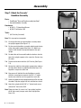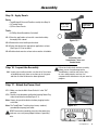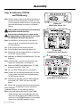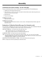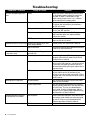
1
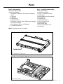
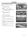
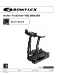
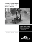
®
®
Bowflex® TreadClimber® 1000, 3000 & 5000
Assembly Manual
Nautilus®
Bowflex®
P/N 001-7142 Rev B (01/09)
Schwinn® Fitness
StairMaster®
Universal®
Nautilus Institute®
Table of Contents
Product Specifications.....................................................................................................................................................1
Important Safety Instructions..........................................................................................................................................2
Before You Assemble........................................................................................................................................................3
Basic Assembly Principles.................................................................................................................................3
Select Your Workout Area..................................................................................................................................3
Machine Mat........................................................................................................................................................3
Parts.....................................................................................................................................................................................4
Hardware............................................................................................................................................................................6
Assembly.............................................................................................................................................................................7
Put the Treadles on the Base.............................................................................................................................7
Connect the Speed and Step Pickup Wires....................................................................................................8
Lock the Treadles.................................................................................................................................................9
Attach the Drive Belt...........................................................................................................................................9
Attach the Uprights...........................................................................................................................................10
Attach the Upright Junction............................................................................................................................11
Attach the Cosmetic Plugs...............................................................................................................................11
Attach the Console/Handlebar Assembly.....................................................................................................12
Attach the Hydraulic Cylinders.......................................................................................................................13
Inspect the Assembly.......................................................................................................................................13
Attach the Frame Covers..................................................................................................................................14
Adjust Speed Sensor and Attach the Rear Cover........................................................................................15
Attach the Drive Covers...................................................................................................................................16
Attach the Side Foot Support Platforms.........................................................................................................16
Apply Decals......................................................................................................................................................17
Inspect the Assembly.......................................................................................................................................17
Attach the Power Cord.....................................................................................................................................17
Calibration (TC 3000 and TC 5000 only)...........................................................................................................18
If Calibration Fails..............................................................................................................................................19
Explanation of Calibration Display Messages..............................................................................................19
Troubleshooting...............................................................................................................................................................20
Exploded Views...............................................................................................................................................................23
Important Contact Numbers..........................................................................................................................................27
Product Specifications
Physical Dimensions
Length
Width
Height
Weight
Shipping Weight
System Capacities
Maximum Weight Capacity
Speed
46 inches (117 cm)
28.5 inches (72.5 cm)
55.25 inches (140.5 cm)
185 pounds (84 kg)
220 pounds (100 kg)
300 lbs (136 kgs)
TC1000
TC3000 and TC5000
0.5 to 3.8 MPH (0.8 to 6.1KPH )
0.7 to 4.0 MPH (1.1 to 6.4 KPH)
Workout Resistance Levels
1 to 12
Warranty LengthSee the Warranty section for full
information per machine type
Component Specifications
Belt Motor
Treadmill Incline
Frame
Operational Voltage
Operational Current
7.75 in x 38.5 in (19.5 cm x 98 cm)
0.5 hp continuous duty
0% Grade
Powder-coated steel
95 to 130 VAC 50 - 60 Hz
12A Max
A short 14 gauge, 3 wire extension cord is permissible.
Regulatory Approvals Marks = c-ETL-US The standard for Safety for Motor-Operated Massage and Exercise Machines, UL 1647, 3rd Ed. and
Motor-Operated Appliances, CAN/CSA-C22.2 No. 68-92
Patent Information
TC1000
U.S. and International Patents Pending
TC3000
TC5000
Assembly Manual
1
Important Safety Instructions
This icon means a potentially hazardous situation which, if not avoided, could result in death or
serious injury.
Obey the following warnings:
Read and understand all warnings on this machine.
Carefully read and understand the Assembly Manual.
• Keep bystanders and children away from the product you are assembling at all times.
• Do not connect power supply to the machine until instructed to do so.
• Make sure assembly is done in an appropriate work space away from foot traffic and exposure to
bystanders.
• Some components of the machine can be heavy or awkward. Use a second person when doing the assembly steps involving these parts. Do not do steps that involve heavy lifting or awkward movements on your own.
• Set up this machine on a solid, level, horizontal surface.
• Do not try to change the design or functionality of this machine. This could compromise the safety and can void the warranty.
• If replacement parts are necessary use only genuine Nautilus® replacement parts and hardware. Failure to use genuine replacement parts can cause a risk to users, keep the machine from operating correctly or void the warranty.
• Do not use or put the machine into service until the machine has been fully assembled and inspected for correct performance in accordance with the Owner’s Manual.
• Read and understand the complete Owner’s Manual supplied with this machine before first use. Keep the Owner’s Manual for future reference.
2
Assembly Manual
Before You Assemble
Basic Assembly Principles
Here are a few basic assembly tips that can make assembly of the Bowflex® TreadClimber® exercise machine quick and
easy.
1.Gather the pieces needed for each step prior to starting the step.
2.Turning towards the right tightens all the bolts and locknuts on your Bowflex® TreadClimber®. Turning towards the left,
loosens them.
3.All of the tools needed for assembly of your Bowflex® TreadClimber® exercise machine have been included. These tools
are only designed for one use. If damaged, substitute any commonly available 9/16” wrench and #2 screwdriver.
Note: A utility knife or scissors will be required during the unpacking and assembly process
(not included).
Select Your Workout Area
Select where you are going to put your Bowflex® TreadClimber® exercise machine carefully. The best place for your
TreadClimber® machine is on a hard, level surface. You will need at least 20 inches (0.5 meters) on each side and in front
of your TreadClimber® machine, and at least 36 inches (0.75 meters) behind it for dismount.
Make sure that the location you choose has a 10A power outlet within reach of the TreadClimber® machine power cord,
preferably to the right side of the machine where you will be less likely to step on the cord during dismount.
Note: The TreadClimber® machine is designed to plug into a grounded, non-GFI outlet only. To determine if your outlet or
circuit breaker is GFI, look for a test and reset button on them. If they have the test and reset button it is a GFI outlet
or circuit breaker.
Further, if you ever perform any repairs on your TreadClimber® machine that require you to lay it on its side, you will need
at least 60 inches (1.5m) to one side of your workout area.
Machine Mat
The Bowflex® TreadClimber® Machine Mat is an optional accessory for the TreadClimber® machine that helps keep
your workout area free from debris and dust. The rubber machine floor mat provides a non-slip surface when mounting
and dismounting the TreadClimber® machine, limits static discharge when you touch the machine, greatly reducing the
possibility of display or running errors. A rubberized mat will protect your flooring when you are performing repairs or
maintenance. Put your Bowflex® TreadClimber® Machine Mat in your selected workout area before begining assembly to
protect your floors and your TreadClimber® machine from damage.
Assembly Manual
3
Parts
Box 1 contains:
Qty: 1
Descr: Rear Cover
Qty: 1
Descr: Control Panel/Handlebar Assembly
Qty: 2
Descr: Plastic Upright Junction Covers
Qty: 2
Descr: Left and Right Side Foot Support Platform
Qty: 1
Descr: Left Side Plastic Frame Cover
Qty: 1
Descr: Right Side Plastic Frame Cover
Qty: 1
Descr: Right Side Plastic Drive Cover
Qty: 1
Descr: Left Side Plastic Drive Cover
4
Assembly Manual
Qty: 2
Descr: Left & Right
Hydraulic
Cylinder
Qty: 1
Descr: Left
Upright
Support
Qty: 1
Descr: Right
Upright
Support
Parts
Box 1 also contains:
Qty:1 Assembly Hardware Bag
Contains the following:
Qty:1 Owner’s Manual Bag
Contains the following:
•The Bowflex TreadClimber Assembly Guide and Owner’s
Manual
• (1) Drive Belt
• Power Cord
• (2) Treadle Decals
•(2) Drive Cover Decals
• TreadClimber® Safety Key *Note: TC1000 Safety Key plugged
into console for shipping.
•Heart Rate Monitor Chest Strap (TC5000 Only)
• (1) #2 Phillips Screw Driver
®
®
• (1) #2 Phillips Screwdriver
• (2) 5/16" x 1 1/2" Button Head Screw
• (1) 3/16" Hex Key
• (12) 5/16" Flat Washers SAE (smaller O.D.)
• (1) 5/32" Hex Key
• (2) 5/16" Acorn Nut
• (1) 9/16" Open End Wrench
• (6) 1/4" x 1" Flat Head Screw
• (2) 5/16" Flat Washers
• (4) 3/8" Cosmetic Plugs
• (14) 5/16" x 1" Button Head Screw
• (16) #10 Phillips
Note: Occasionally extra parts are included.
Box 2 contains the TreadClimber® treadles
Cylinder Stud
Qty: 1
Descr: TreadClimber® Treadle Assembly
Box 3 contains the TreadClimber® base
Qty: 1
Descr: TreadClimber® Base
Assembly Manual
5
Hardware
Hardware:
Qty: 6
Descr: 1/4” x 1” Flat Head Screw
Qty: 2
Descr: 5/16” x 1 1/2” Button Head Screw
Qty: 16
Descr: #10 Phillips Head Screw
Qty: 14
Descr: 5/16” x 1” Button Head Screw
Qty: 2
Descr: 5/16” Flat Washer
Qty: 12
Descr: 5/16” Flat Washer SAE
Qty: 4
Descr: 3/8” Cosmetic Plugs
Qty: 2
Descr: 5/16” Acorn Nut
Tools:
Qty: 1
Descr: #2 Phillips Screwdriver
Qty: 1
Descr: 3/16” Hex Key
Qty: 1
Descr: 9/16” Open End Wrench
Qty: 1
Descr: 5/32” Hex Key
Parts:
Qty: 1
Descr: Drive Belt
6
Assembly Manual
Qty: 1
Descr: Safety Key with Clip (Models TC3000 & TC5000 only.)
Assembly
Step 1: Put the Treadles on the Base
Parts:
• TreadClimber® Base Assembly
• TreadClimber® Treadle Assembly
Hardware:
• (4) 3/8” X 1 1/4” Hex Bolts (preassembled)
Note: H
ardware is only hand tightened. Finish tightening
the hardware in Step 1-5 below.
Figure 1-1
Tools:
• 9/16” Open End Wrench (included)
• Scissors or other cutting tool
• Ruler
Note: This step requires two people.
1-1Unlock the latch lever (see Figure 1-1).
Align roller casting so it lays flush
on base
1-2Lower the tower treadle assembly onto base with two
people.
1-3Align roller casting flush to the base (See Figure 1-2)
1-4 U
se a ruler to center the treadles between the upright
bases.
1-5 T ighten the (4) 3/8” x 1 1/4” Hex Bolts on the rear roller
casting and base with the 9/16” open end wrench (See
Figure 1-3).
Figure 1-2
Note: Tighten the outside bolts on the rear roller casting first, then the inner bolts.
1-6 Cut the treadle zip tie located underneath the treadles.
Figure 1-3
Assembly Manual
7
Assembly
Step 2: C
onnect the Speed and Step Wires
(TC3000 and TC5000 only)
Parts:
•TreadClimber® Base and Treadle assembly from Step 1
2-1Connect the Speed Wires (See Figure 2-1).
2-2Connect the Step Wires (See Figure 2-2). Push any excess
wire through holes in frame (See Figure 2-3).
Speed Wire
Figure 2-1
Note: T he TC1000 is not equipped with step sensor function. Tuck
unused step sensor wires through hole in frame.
Figure 2-2
Figure 2-3
8
Assembly Manual
Assembly
Step 3: Lock the Treadles
Parts:
•TreadClimber® Base and Treadle assembly from Step 2
3-1Line up the treadles parallel to each other and cut the zip
tie connecting them.
3-2Move the locking lever down and to the left and then up into
the locked position until it clicks (See Figure 3-1).
3-3From the front of the machine, press down on each treadle
individually until they lock into the down position.
Figure 3-1
Lever in locked position
The treadles might unlock during workout if they are not fully engaged.
Step 4: Attach the Drive Belt
Parts:
•TreadClimber® Base and Treadle assembly from Step 3
•(1) Drive Belt
Tools:
• 3/16” Hex Key (included)
4-1Position the drive belt over the roller pulley and the motor
pulley (See Figure 4-1).
Figure 4-1
4-2 M
ake sure that the belt is installed correctly into the grooves
of the pulleys (See Figure 4-2).
4-3 R
emove the motor shipping bolt from the motor pan with
the 3/16” hex key (See Figure 4-3).
Note: R
emoving the shipping bolt will make the drive belt tight with
spring-loaded tension. Be sure to keep the bolt in a safe place
in case the machine must be disassembled for shipping or part
replacement.
4-4 Put the unit in the upright position.
Figure 4-2
Figure 4-3
Assembly Manual
9
Assembly
Step 5: Attach the Uprights
Parts:
•TreadClimber® Base and Treadle assembly from Step 4
• (1) Left Upright Support & Hydraulic Cylinder
• (1) R
ight Upright Support & Hydraulic Cylinder
Hardware:
• (2) 5/16” x 1” Button Head Screws
Tools:
Figure 5-1
• 3/16” Hex Key
5-1Screw a 5/16” x 1” button head screw half way into the
outside of the left and right lower upright brackets of the
base assembly (See Figure 5-1).
5-2Put the left upright on the left upright bracket (See Figure
5-2) so that it rests on the button head screw (See Figure
5-3). The cylinder bracket will be at the top and face the
rear of the machine.
Note:Make sure the decal on the upright support faces outward from
the machine.
Figure 5-2
5-3Repeat on the opposite side.
Figure 5-3
10
Assembly Manual
Assembly
Step 6: Attach the Upright Junction
Parts:
•TreadClimber® Base and Treadle assembly from Step 5
• (2) Plastic Upright Junction Covers
6-1Put the plastic upright junction cover on the top of the left
upright support (See Figure 6-1).
Note:Make sure the plastic upright junction cover extends to the
rear of the machine.
6-2 Repeat on opposite side.
Figure 6-1
Assembly Manual
11
Assembly
Step 7: Attach the Console/
Handlebar Assembly
Parts:
• TreadClimber® Base and Treadle assembly from Step 7
• Console/Handlebar Assembly
Hardware:
• (6) 5/16” x 1” Button Head Screws
• (6) 5/16” Flat Washers SAE
Figure 7-1
Tools:
• 3/16” Hex Key (included)
Note: This step requires two people.
7-1 L ift and position the console/handlebar assembly above
the upright supports (See Figure 7-1).
7-2Put the console/handlebar assembly cable through the top
of the right upright support (See Figure 7-2). Make sure
that the cable extends throught the bottom of the right
upright.
Figure 7-2
7-3Put both sides of the console/handle bar brackets into the
tops of the upright supports at the same time. Do not crimp
the cable.
7-4Tighten the hardware with the 3/16” hex key (See Figure
7-3).
Figure 7-3
7-5Connect the cable from the upright support to the cable on
the right side of the base upright bracket (See Figure 7-4).
Repeat this step on the other side.
7-6One person will hold the Console/Handlebar assembly
while the second person removes the 5/16” x 1” button
head screw at the base of the support from each side.
7-7Lower the upright on to the upright bracket base. Do not crimp
the cables. Drop the upright until flush with the base frame.
Figure 7-4
7-8 A
ttach the upright with (6) 5/16” x 1” button head screws
and (6) 5/16” flat washers SAE.
Note: Tighten the front (2) screws first (1 per upright) and then
the (4) side screws, two per outer side of upright (See
Figure 7-5).
12
Assembly Manual
Figure 7-5
Assembly
Step 8: Attach the Cosmetic Plugs
Hardware:
• (4) Cosmetic Plugs
8-1Insert the cosmetic plugs into the holes on the top, inside and
outside of the left upright support (See Figure 8-1).
8-2 Repeat on opposite side.
Figure 8-1
Step 9: Attach the Hydraulic Cylinders
Parts:
• TreadClimber® Base and Treadle assembly from Step 8
Hardware:
•
•
•
•
(2) 5/16” x 1 1/2” Button Head Screws
(2) 5/16” Acorn Nuts
(2) 5/16” x 1” Button Head Screws (preassembled)
(2) 5/16” Flat Washers (preassembled)
Tools:
Figure 9-1
• 3/16” Hex Key (included)
• 9/16” Open End Wrench (included)
Note: This step requires two people.
9-1Attach the hydraulic cylinder to the upright bracket with (1) 5/16”x 1 1/2”
Button Head Screw and (1) 5/16” Acorn Nut (Figure 9-1).
Note:Make sure that the single white arrow, located on the Workout Level
Setting Dials at the top of the hydraulic cylinders, is pointing up and to
the rear of the machine.
9-2Remove the pre-installed (1) 5/16” x 1” Button Head Screw and (1) 5/16”
Flat Washer from treadle. Lift treadle and slide the lower shock eyelet
onto the treadle stud.
Figure 9-2
9-3Attach the hydraulic cylinder with the (1) 5/16” x 1” button head screw
and (1) 5/16” flat washer (Figure 9-2).
9-4Tighten the hardware with the Hex Key and Open End Wrench.
Assembly Manual
13
Assembly
Step 10: Inspect the Assembly
10-1 Remove the plastic film from the console face.
10-2Inspect all of the attachments and securely tighten all of
the bolts before proceeding to Step 11.
Step 11: Attach the Frame Covers
Parts:
•TreadClimber® Base and Treadle assembly from Step 10
• (1) Left Plastic Frame Cover
• (1) R
ight Plastic Frame Cover
Hardware:
• (6) #10 Phillips Head Screws
Figure 11-1
Tools:
• #2 Phillips Head Screwdriver (included)
11-1 Attach the left and right Plastic Frame Covers to the sides
of the base frame with (6) #10 Phillips Head Screws (3 per
side) and the provided #2 Phillips screwdriver (See Figures
11-1 and 11-2).
Figure 11-2
14
Assembly Manual
Assembly
Step 12: Adjust Speed Sensor and Attach the Rear Cover
Parts:
•TreadClimber® Base and Treadle assembly from Step 11
• (1) Rear Cover
Hardware:
Figure 12-1
• (4) #10 Phillips Head Screws
Tools:
• #2 Phillips Head Screwdriver (included)
12-1 Hold a stiff business card, ID card, or similar object onto
the inside of the drive pulley. Adjust the speed sensor
towards the card until it just makes contact.
Figure 12-2
12-2 Remove object.
12-3 Attach the rear cover to the back of the frame with the (4)
#10 Phillips Head Screws (2 per side) and the provided #2
Phillips Head Screwdriver (See Figure 12-1 and 12-2).
Assembly Manual
15
Assembly
Step 13: Attach the Drive Covers
Parts:
•TreadClimber® Base and Treadle assembly from Step 12
• (1) Left Plastic Drive Cover
• (1) R
ight Plastic Drive Cover
Hardware:
• (6) #10 Phillips Head Screws
Tools:
Figure 13-1
• #2 Phillips Head Screwdriver (included)
13-1 Attach the left and right Plastic Drive Covers to the sides of the
base with (6) #10 Phillips Head Screws (3 per side) and the provided
#2 Phillips screwdriver (See Figures 13-1). Install upper screw first.
Note: Do not tighten hardware until all screws have been installed.
Step 14: A
ttach the Side Foot
Support Platforms
Parts:
•TreadClimber® Base and Treadle assembly from Step 13
• (1) Left Foot Support Platform
• (1) R
ight Foot Support Platform
Hardware:
• (6) 1/4” x 1” Flat Head Screws
• 5/16” Hex Key (included)
Figure 14-1
Tools:
14-1Attach the right and left side foot support platforms to each treadle
with (6) 1/4” x 1” Flat Head Screws (3 per side) (See Figures 14-1
and 14-2).
Figure 14-2
16
Assembly Manual
Assembly
Step 15: Apply Decals
Parts:
•TreadClimber® Base and Treadle assembly from Step 14
• (2) Treadle Decals
• (2) Drive Cover Decals
Treadle decal
1 per side
Drive decal
1 per side
Tools:
• #2 Phillips Head Screwdriver (included)
15-1Clean the application surface with a wet cloth and dry
thoroughly with a towel.
Figure 15-1
15-2Remove the relase backing on the decal.
15-3Center the decal on the appropriate application surfaces
(See Figure 15-1) for locations.
15-4Rub the decal onto the surface to force out the air bubbles.
Illustration 15-A:
TreadClimber® Drive and
Treadle Decals
Step 16: Inspect the Assembly
16-1Inspect your machine to make sure that all of it has been
assembled correctly, there are no loose or missing parts
and that all of the hardware has been tightened.
F ailure to visually check and test assembly
before use can cause damage to the
TreadClimber® machine and serious injury
to users and bystanders and can also
compromise the effectiveness of your exercise
program.
Step 17: Attach the Power Cord
17-1 M
ake sure that the Main Power Switch is in the “Off”
postition.
17-2 Carefully insert the power cord into the Incoming Power Plug
at the rear of the base unit (See Figure 17-1).
Note: A
lways plug cord into the base before plugging into the
wall outlet.
Note: T he TreadClimber® machine plugs into any standard,
grounded (three-prong) wall outlet.
Figure 17-1
EVER remove the grounding prong from the power plug
N
and never use a two-prong adapter without a grounding
wire.
Incoming Power Plug
Main Power Switch
Assembly Manual
17
Assembly
Step 18: C
alibration (TC3000
and TC5000 only)
Note: D
uring calibration, observe the walking belt alignment.
Belts do not need to be perfectly centered, but if they
are far enough from center to cause a scraping sound,
follow the belt alignment instructions in the Owner’s
Manual.
Figure 18-1
Main Power Switch “On”
Failure to calibrate your machine prior to use could result in machine failure and could cause injury.
During the entire calibration process, stand on the side
foot support platforms or rubber mat only. Do not stand on
the walking belts during this entire process.
Note: Re-calibration is also neccessary in the event of a
power outage or if a component like a belt or motor
has been replaced.
18-1 Plug the power cord into the the wall outlet.
18-2 Turn on the Main Power Switch (See Figure 18-1).
18-3Stand on the side foot support platforms or rubber floor
mat. Do NOT stand on the belts.
Figure 18-2
TC5000 Power & Slower Buttons
18-4Hold down the POWER and SLOWER buttons. Insert the
Safety Key.
Note: If
the Safety Key is not fully inserted into the safety
keyhole, the TreadClimber® will not operate.
18-5Release the POWER and SLOWER buttons. The TIME
display will read “CAL”, PrSS”,”Strt”.
0/7%2-/$5,%
É
18-6 Press the START/STOP button to start calibration.
4/34!24
0RESS*"7,
Note: The belts will start and stop and the displays will show
various numbers that relate to the calibration process.
Do NOT interrupt calibration.
18-7Calibration will take about 3 minutes. When calibration
has finished “CAL” “PASS” will show in the TIME
display.
18-8 Remove and re-insert the Safety Key to clear the display.
When the Bowflex® TreadClimber® exercise machine has
completed calibration, you may begin your workout.
Note: D
uring calibration the 30 meter LED on the TC5000
signifies the belt speed sensor, 305 meters LED is the
step sensor. Some models of the TC 3000 will show the
step sensor in the DISTANCE window as a heart and the
speed sensor in the SPEED window as a heart.
18
Assembly Manual
--
Figure 18-3
TC3000 Power & Slower Buttons
Assembly
If Calibration Fails (Screen Displays “Cal Fail” Message):
This error usually indicates that the console is unable to determine the speed of the belts. Take the following steps:
1. Unplug the unit and remove the three back covers.
2.Hold a stiff business card, ID card, or other similar onto the inside of the drive pulley. Adjust the speed sensor towards the card until it just makes contact.
3. Remove the card.
4. Plug unit in and recalibrate.
If calibration is successful:
• Replace the three back covers.
If calibration is not successful:
•Leave plastic covers off and contact customer care for assistance. ( See Important Contact Numbers page at the
back of this manual).
Explanation of Calibration Display Messages (for information only):
During calibration, the TIME display will show you text messages updating you as to the status of calibration. When there
is no text message in the TIME display window, the other displays will show the following:
HEART RATE (TC5000 Only) – will show the status of the motor control relay.
• “ON” signifies the power relay is on and energizing the motor.
• “OFF” signifies the motor control relay is off and not energizing the motor.
CALORIES/CAL PER MIN – will show the version number of the software.
TIME – will show either a text message regarding auto-calibration (“d0nE”, “Strt”, etc.) or the actual Pulse Width
Modulation (PWM) number (a number that provides digital information about base unit functions to the console) if
START/STOP, FASTER or SLOWER is pressed during calibration.
MILES/TOTAL STEPS (DISTANCE/MILES for TC3000) – will show the calibration of the total step count.
SPEED – will display the actual belt speed during the calibration function.
Assembly Manual
19
Troubleshooting
Condition / Problem
Unit will not power up/turn on/
start
Things to Check
Outlet
Make sure outlet is functioning correctly. Verify
this by plugging another object (ex: lamp) into
the outlet. If outlet is connected to a light
switch, check to make sure it is on. If outlet is
not functioning find a working outlet.
Power cord not plugged in
Make sure the power cord is firmly secured to
A/C inlet on the unit and firmly inserted into a
non-GFI wall socket.
Power switch turned off
Make sure the power switch at the rear of the
unit is in the “ON” position.
Safety key not plugged in
Plug Safety Key into console (See Emergency
Stop Procedure within the Important Safety
Precautions section).
LED Diagnostic needed
Remove rear plastic covers and contact customer service for assistance.
Speed displayed is not accurate Display set to wrong unit of measure. (English/Metric)
Heart rate not displayed while
using chest strap
Walking belt misalignment
Speed dependent grinding or
scraping noise in all modes
20
Assembly Manual
Solution
Change display units (See Owner’s Manual).
Out of calibration
Re-calibrate machine (See Calibration procedure
in Owner’s or Service Manual).
Transmitter not making good contact with skin
Moisten skin contact area on the chest strap.
Electromagnetic interference
Turn off any television, AM radio, microwave, or
computer within 6 feet (2 meters) of the TreadClimber® fitness machine.
Chest strap transmitter
Test chest strap with another HR monitoring
device such as HR watch or a machine at a gym.
If transmitter has good skin contact and still is
not found to be emitting HR signal, replace chest
strap transmitter.
HR receiver
If chest strap is known to work with other
devices and no sources of interference are
present, or console has been tested with a Pulse
Simulator and is not receiving the signal, replace
the HR receiver.
Rear belt guides
Belts should ride on top of triangular black belt
guides at rear of treadles.
Tracking adjustment
Belts are not required to be perfectly centered
and are typically farther out in the rear than they
are in the front. This may vary depending on
user’s stride. If belt is tracking to one side far
enough to cause rubbing of belt follow belt alignment procedure in Owner’s Manual.
Belt alignment
Check walking belt alignment. Belt contact with
metal guides under treadle can make loud grinding sound. If belts are misaligned follow belt
alignment procedure in Owner’s Manual.
Rollers or motor
Contact customer service for further assistance.
Troubleshooting
Condition / Problem
Hesitation or belt slipping
when walking on unit
Things to Check
Solution
Belt tension
If belt hesitates or slips when walking on unit
it may be caused by either a loose walking belt
or a loose drive belt. To determine the cause
perform the following test: Stand beside TreadClimber® fitness machine and set speed to 2
MPH. Step on one treadle and attempt to stop
movement. If one belt stops but roller at rear
and other belt continue to turn walking belt tension should be adjusted. If both belts stop but
motor is still turning the drive belt tension should
be adjusted.
Walking belt tension
Adjust walking belt tension at the front of the unit
using the provided hex wrench on the exposed
adjustment bolts located on each side of each
front roller. Be sure to adjust both bolts on each
roller the same amount as to not disrupt belt
alignment. Tighten (turn clockwise) each adjustment bolt in full turn increments. After each
adjustment, restart unit and check to see if belt
slippage has been eliminated. Repeat if necessary. If slipping feel persists after several adjustments, stop and refer to drive belt checklist.
Drive belt
Unplug power from unit. Wait 5-minutes to
ensure no residual power remains. Turn unit on
its side to expose its underside. Verify shipping
bolt has been removed. If bolt is not present,
return machine to upright posiition. Remove
left rear plastic cover to expose “v” belt drive
line and motor. Tighten nut on the motor tension
bolt located on front side of motor in 1/2 turn
increments until drive belt slippage is eliminated
- DO NOT OVER TIGHTEN. Replace cover when
finished.
“Tick” sound once per revolution or scraping noise from
under treadle
Belt alignment
Belt seam may be contacting metal belt guide
under treadle. Slight adjustment of belt should
alleviate noise. Follow belt alignment procedure
in Owner’s Manual.
Floors Climbed Display not
updating
Size of steps taken
In order for a step to register, the pedals must
pass each other completely. This ensures that
the magnet on the treadle passes the step sensor. Make sure treadles are not locked in treadmill mode and that they are moving enough to
register a step.
Step sensor
Be sure step sensor wire is connected at rear of
machine.
Assembly Manual
21
Troubleshooting
Condition / Problem
Knocking noises when unit is
operating in TreadClimber or
stepper mode, but not in treadmill mode
Belts stop turning and “err LS”
or “err OS” is displayed
22
Assembly Manual
Things to Check
Solution
Treadle alignment
Make sure treadles are centered between
uprights and treadle is not contacting upright
during use. If not centered remove rear plastic
covers to access rear baseplate bolts. Loosen
bolts slightly to allow treadles to be centered.
Once centered tighten outer two bolts securely
then tighten inner bolts securely.
Drive pulley and flywheel
pulley
Unplug power from Unit. Wait at least 5 minutes.
Remove left side plastic drive cover to expose
“v” belt drive line. Using a ½” wrench, tighten
the bolt that attaches the 4 ½” drive pulley to
the drive shaft while holding the drive rollers
still. Also, using a 5/32” hex wrench, tighten the
setscrew on the flywheel motor pulley. Reinstall
plastic drive cover.
Igus bushing
If knocking sound seems to be coming directly
from the rear roller, check igus bushings and
replace if cracked.
Hydraulic cylinder bolts
Check and tighten both upper and lower bolts
that connect the hydraulic cylinders to the unit.
Calibration
Re-calibrate machine using Owner’s Manual
calibration procedure.
Speed sensor
1. Cycle power off and on.
2. Put the machine in calibration mode (see Calibration procedure in Owner’s Manual) but do not
start the calibration routine.
3. Remove right rear plastic cover to view LED
diagnostics on control board.
Caution: Machine is on. Current is active!!
4. Locate LED D on the motor controller board.
LED may be lit or unlit.
5. Manually advance the treadle with your foot,
and check if LED D is blinking.
6. If LED D is not blinking, then the speed sensor
is not supplying a signal. Check that the speed
sensor wire is plugged into the motor controller
board, to the connection labeled “P1”. Check
connection of speed sensor to jumper wire.
Check speed sensor adjustment (use business
card to set gap between sensor and pulley). If
LED D still does not flash replace sensor.
I/O cables
If LED D is flashing when the belts are turning
but err LS or OS persists check connections and
for signs of visible damage to any of the three I/O
cables. If no damage, check continuity using a
multi-meter. If a multi-meter is not available contact customer service for replacement cables
and further assistance.
Exploded Views
Ordering Replacement Parts
Call a Bowflex® TreadClimber® Representative at 1-800-NAUTILUS (1-800-628-8458) to order replacement parts and
get assistance with your specific replacement or service requirements.
TC1000
Console Assembly
Overlay
(Not illustrated)
Console Top
Electronics
Limit Switch
Tether Housing
Assembly
Tether Housing
Console Bottom
TC Handlebar
Upright Junction
Covers
Round Plug
Plugs
Upright
Upright
Cylinders/Shocks
Assembly Manual
23
Exploded Views
Walking Belts
R. Rear
Belt Guide
(L. Rear Belt Guide
Not Shown)
Deck
Front Roller
Keeper
R. Outer
Treadle Skin
Foot Platform
Front Roller
Bracket
Front Roller
Inner Treadle
Skin (L & R)
Front Roller
Bracket
L. Outer
Treadle Skin
Treadle
Friction
Block
Belt Guide
Rear Roller
Bracket
Rear Roller Bracket
Inner Roller
Bracket
Right Drive
Bracket
Single
Roller
Bearing
Foot Platform
Shaft Spacer
Bearing
Speed Sensor
Drive Pulley
Treadle Stop
Bracket
Treadle Stop
Blocks
24
Assembly Manual
Left Drive
Bracket
Drive Base
Center
Rear Drive
Base
M. Pivot Bushing
Washer Kit*
*Middle Pivot Bushing/Washer Kit:
(4) TC Igus® Bearing
(8) TC Igus® Washer
(4) TC Treadle Pivot Bushing
Main Frame
Left Drive Cover
Left Frame Cover
Base Cover
Safety Plate
Red Cap
TC Foot
gs
Plu
Wheels
Lever Latch
Bracket
gs
Plu
Rear Cover
Cord Bracket
Locking Latches
Latch Offset Bracket
Latch Arm
Assembly Manual
Ten
Motor Base
M
r
oto
Kit
tor
Mo
n
sio
Right Drive Cover
Right Frame Cover
Motor Controller
Exploded Views
25
Important Contact Numbers
UNITED STATES OFFICES
TECHNICAL/CUSTOMER SERVICE
Phone: 800-NAUTILUS (800-628-8458)
E-mail: [email protected]
CORPORATE HEADQUARTERS
Nautilus, Inc.
World Headquarters
16400 SE Nautilus Drive
Vancouver, Washington, USA 98683
Phone: (800) NAUTILUS (800) 628-8458
INTERNATIONAL OFFICES
INTERNATIONAL CUSTOMER SERVICE
Nautilus International S.A.
Rue Jean Prouvé
1762 Givisiez / Switzerland
Tel: + 41 26 460 77 77
Fax: + 41 26 460 77 70
E-mail: [email protected]
GERMANY and AUSTRIA
Nautilus International GmbH
Albin-Köbis-Str. 4
51147 Köln
Tel: + 49 02203 2020 0
Fax: + 49 02203 2020 45 45
ITALY
Nautilus Italy S.r.l., Via della Mercanzia, 103
40050 Funo di Argelato - Bologna
Tel: + 39 051 664 6201
Fax: + 39 051 664 7461
SwITZERLAND
Nautilus Switzerland SA
Rue Jean-Prouvé 6
CH-1762 Givisiez
Tel: + 41 26 460 77 66
Fax: + 41 26 460 77 60
Please supply the serial number of your machine and the date of
purchase when you call Nautilus. Use the space in the boxes below
to write down this information. Dial the number of the office close
to you.
Serial Number
Date of Purchase
United Kingdom
Nautilus UK Ltd
4 Vincent Avenue
Crownhill, Milton Keynes, Bucks, MK8 0AB
Tel: + 44 1908 267 345
Fax: + 44 1908 267 345
chinA
Nautilus (Shanghai) Fitness Co., Ltd.
7A No.728, Yan’an Road (West)
200050 Shanghai, China
Tel: + 86 21 523 707 00
Fax: + 86 21 523 707 099
Assembly Manual
27
®
®
Printed in China
©2008. Nautilus, Inc. All rights reserved. Nautilus, the Nautilus Logo, TreadClimber, the TreadClimber Logo, Bowflex, Bowflex Logo, StairMaster and Nautilus Institute are either registered trademarks or trademarks of Nautilus, Inc. Schwinn is a registered trademark. All other trademarks are owned by their respective companies. Nautilus, Inc., World Headquarters, 16400 SE Nautilus
Drive, Vancouver, WA 98683 1-800-NAUTILUS www.nautilus.com
Nautilus®
Bowflex®
Schwinn® Fitness
StairMaster®
Universal®
Nautilus Institute®