1
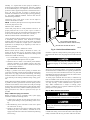
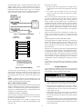
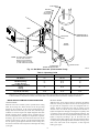
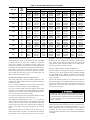
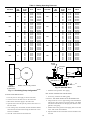
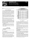
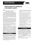
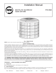
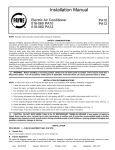
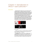
50YA
Water Source Comfort System
Installation and Start-Up Instructions
NOTE: Read the entire instruction manual before starting the
installation.
SAFETY CONSIDERATIONS
Improper installation, adjustment, alteration, service, maintenance,
or use can cause explosion, fire, electrical shock, or other
conditions which may cause personal injury or property damage.
Consult a qualified installer, service agency, or your distributor or
branch for information or assistance. The qualified installer or
agency must use factory-authorized kits or accessories when
modifying this product. Refer to the individual instructions packaged with the kits or accessories when installing.
Follow all safety codes. Wear safety glasses and work gloves. Use
quenching cloth for brazing operations. Have fire extinguisher
available. Read these instructions thoroughly and follow all
warnings or cautions attached to the unit. Consult local building
codes and the National Electrical Code (NEC) for special installation requirements.
Recognize safety information. This is the safety-alert symbol .
When you see this symbol on the unit or in instructions and
manuals, be alert to the potential for personal injury.
Understand the signal word DANGER, WARNING, or CAUTION. These words are used with the safety-alert symbol. DANGER identifies the most serious hazards which will result in severe
personal injury or death. WARNING signifies hazards that could
result in personal injury or death. CAUTION is used to identify
unsafe practices which would result in minor personal injury or
product and property damage.
Electrical shock can cause personal injury or death. Before
installing or servicing system, always turn off main power to
system. There may be more than 1 disconnect switch. Turn
off accessory heater power if applicable.
INSTALLATION
Step 1—Check Jobsite
HORIZONTAL UNITS
Because horizontal units are designed for installation above a false
ceiling or ceiling plenum, access becomes an important consideration. Be sure that the site chosen for unit installation provides
enough clearance to allow easy maintenance or servicing of the
unit without removal from the ceiling. Refer to Fig. 1 for a typical
horizontal unit.
INSTALLATION GUIDELINES
1. Provide a hinged access door (inconcealed-spline or plaster
ceilings), or removable tiles (in T-bar or lay-in ceilings).
The access opening must be large enough to allow the service
technician to service the unit (including compressor removal
and replacement), and to permit removal of the unit. See Fig.
2 for base unit dimensions.
Fig. 1—Model 50YAH
A93331
2. Provide easy access to hanger brackets, water valves, and
fittings, and allow screwdriver clearance to access panels, the
discharge collar, and all electrical connections.
3. If a return duct is used, be sure to provide a duct slot for filter
replacement.
4. To allow removal of the unit, do not run obstructions (for
example, piping, electrical cable, etc.) under the unit.
5. Minimize obstructions in the conditioned space beneath the
unit whenever possible. A manual, portable jack can then be
used to lift and support the weight of the unit during
installation or servicing.
VERTICAL UNITS
While vertical units are typically installed in a floor level closet or
basement. The unit access guidelines for vertical units are very
similar to those described for horizontal units. Refer to Fig. 2 for
base unit dimensions and Fig. 3 for condensate trap installation.
UNIT LOCATION
1. Provide adequate clearance for filter replacement and drain
pan cleaning. Do not allow piping, conduit, etc. to block filter
access.
2. Provide sufficient access to allow maintenance and servicing
of the fan and fan motor, compressor, and coils.
3. Provide an unobstructed path to enable removal of the unit
from the closet or utility room.
4. Provide ready access to water valves and fittings, and allow
screwdriver access to unit side panels, discharge collar, and all
electrical connections.
Step 2—Check Unit
Be sure to inspect the carton or crating housing each unit as it is
received at the job site. Verify that all items have been received
and that there is no visible damage; note any shortages or damage
on all copies of the freight bill. In the event of damage or shortage,
remember that the purchaser is responsible for filing the necessary
claims with the shipping company.
Manufacturer reserves the right to discontinue, or change at any time, specifications or designs without notice and without incurring obligations.
Book 1 4
PC 101
Catalog No. 565-188
Printed in U.S.A.
Form 50YA-1SI
Pg 1
7-93
Replaces: New
Tab 5a 5a
A
Vertical Models
UNIT SIZE
009,012
015,019
024,030
036
042-060
A (IN.)
24-1/8
37-1/2
37-1/2
42
43-3/16
B (IN.)
19-1/8
21-1/8
21-1/8
25-5/16
28-1/8
C (IN.)
19-1/8
21/1/8
18-1/8
25-5/16
28-1/8
C
B
A
C
B
Horizontal Models
UNIT SIZE
009,012
015,019
024,030
036
042-060
Fig. 2—Base Unit Dimensions
2
A (IN.)
11-1/8
17
19
21
21
B (IN.)
20
20
20
20
36-1/4
C (IN.)
34
43
43
47
36-1/4
3. Verify that the refrigerant tubing is free of kinks or dents, and
that it does not touch other unit components.
4. Inspect all electrical connections; connections should be clean
and tight at the terminals. The compressors are internally
spring-mounted. Those equipped with external spring vibration isolator must have bolts loosened and shipping clamps
removed.
Step 3—Mounting the Unit
MOUNT UNIT—HORIZONTAL
While horizontal units may be installed on a suitable surface strong
enough to hold their weight, they are typically suspended above a
ceiling or within a soffitt using field-supplied, threaded rods to
support the weight. See Fig. 4 for elevation line information.
1″
3″
PITCH DOWN
1/4 IN. PER FT
ELA
WH VATIO
EN
MOUN LINE
NTE
D LE
CONDENSATE
TRAP
Fig. 3—Condensate Trap
1/4″
VEL
A93332
Loosen the compressor mounting bolts to remove the 3 shipping
blocks if equipped before installation.
A periodic maintenance checklist is provided in the maintenance
section to outline recommended maintenance schedules. Do not
substitute these checklist for the detailed information found in the
appropriate sections of this manual.
Fig. 4—Elevation Line
STORAGE
If the equipment is not needed for immediate installation upon its
arrival at the job site, it should be left in its shipping carton and
stored in a clean, dry area of the building, or in a warehouse. Units
must be stored in an upright position at all times. If carton stacking
is necessary, stack units as follows: horizontal units, maximum 4
high; vertical units up to and including model 060, 3 high. Do not
remove any equipment from its shipping package until it is needed
for installation.
A93333
A mounting kit (which includes 4 mounting brackets and vibration
isolators) is shipped inside the blower compartment of the unit.
Attach the brackets and isolators to the bottom corners of the unit.
Then use 4 field-supplied threaded rods to suspend the unit. (See
Fig. 5.)
3/8″
THREADED ROD
UNIT PROTECTION
Once the units are properly positioned on the job site, they must be
covered with either a shipping carton, vinyl film, or an equivalent
protective covering; open end of pipes stored on the job site must
be capped. This precaution is especially important in areas where
painting, plastering, or spraying of fireproof material, etc. is not
yet complete. Foreign material that accumulates within the units
can prevent proper start-up and require costly clean-up operations.
VIBRATION
ISOLATOR
Before installing any of the system components, be sure to
examine each pipe, fitting, and valve, and remove any dirt found
on these components.
UNIT
(REF)
HEX NUT
WASHER
Do not use these units as a source of heat during construction of
the building since the filters will quickly fill with construction dirt
and debris. It is strongly recommended that an alternative means of
providing temporary heat be used.
Fig. 5—Hanger Kit
A93334
Remember that the unit must not be mounted flush with the floor
slab above, but should hang clear and be supported only by the
mounting bracket assemblies. A minimum of 30 in. is recommended for fan section, compressor section, and electrical access.
Allow 1 ft clearance for non-ducted return-air flow.
INSPECT UNIT
To prepare a unit for installation, complete the instructions listed
below:
1. Compare the electrical data on the unit nameplate with
ordering and shipping information to verify that the correct
unit has been shipped.
Unit installation within the plenum should provide adequate
clearance for filter removal. On those applications with a return air
plenum, a slot for filter removal (i.e., toward the front) must be
provided.
2. Do not remove the cardboard carton until the unit is ready for
installation.
3
Normally it is required that the heat pump be installed in a
protected space inside the conditioned area. If the unit is installed
in an unconditioned space, it is imperative that it be isolated and
protected so that its physical temperature is maintained at 60°F or
above. All water pipes that are subject to freezing must be
insulated. All connections to the heat pump by ducting, plumbing,
etc., must follow ASHRAE standards. All local codes must be
followed during installation.
Locating the unit in crawl spaces or attics in areas subject to
extreme cold should be avoided.
NOTE: An auxiliary drain pan at least 4 in. larger than the bottom
of the heat pump must be used.
MOUNT UNIT—VERTICAL
Vertical heat pump units are usually installed on the floor. To
properly isolate the unit, be sure to place a piece of rubber or
neoprene under the unit; the pad should extend beyond the edges
of the unit, and should be 3/8-to l/2-in. thick. (See Fig. 6.)
ISOLATION
PAD
SOUND ATTENUATION—HORIZONTAL UNITS
Correct placement of the horizontal unit can play an important part
in minimizing sound problems. Since ductwork is normally
applied to these units, the unit can be placed so that the principal
sound emission is outside the occupied space in sound-critical
applications. A fire damper may be required by a local code if a
fire wall is penetrated.
INSULATED SOUND BAFFLE
(OPEN BOTH ENDS AND BOTTOM)
RETURN AIR LOUVER OR GRILLE
A93335
SOUND ATTENUATION—VERTICAL UNITS
Fig. 6—Vertical Sound Attenuation
Because vertical units are usually in basements or closets , the
location of the unit often serves as the primary means of sound
attenuation. (See Fig. 6.) Additional measures for reducing sound
transmission include the following:
Insulation is required on all exposed loop water piping. If the loop
temperature falls below 60°F, the piping will sweat and suffer heat
loss.
1. Use a sound baffle, as shown in Fig. 6, to attenuate line-ofsight sound radiated through the return-air grilles.
2. Mount the unit on a rubber or cork isolation pad to minimize
vibration transmission to the building structure (The entire
base of the unit—not just the corners—should rest on the pad
to ensure adequate isolation.)
Failure to insulate loop piping may result in damage from
condensate dripping on surrounding equipment and structures.
Though the horizontal run of the condensate hose is usually too
short to pose any drainage problems, it is important to remember
that horizontal runs of condensate line are typically pitched at least
1 in. for every 10 ft of run in the direction of flow. Low points and
unpitched piping cannot be allowed, since dirt will collect in these
areas and cause stoppage and overflow.
Step 4—Make Duct Connections
A flange is provided at the blower opening to facilitate duct
connections. A flexible connection must be made between the heat
pump and to any supply and return metal ducting. All ducting
should be insulated to avoid heat loss in both heating and cooling
cycles and keep from forming condensate during cooling operation.
To ensure proper condensate flow from units, a condensate trap
must be installed at each unit with the top of the trap positioned
below the unit condensate drain connection. Trap must be at least
3 in. deep. (See Fig. 3.) Pitch condensate line to open drain or
sump. When condensate line is subject to sweating, proper
material or insulation may be required. Condensate trap must be
primed prior to unit operation.
Existing ductwork should be checked to ensure that proper airflow
is possible. The factory specifications on the fan capacity must be
checked to ensure that the correct amount of air will pass through
the heat pump. Check all existing ducts for leaks and repair before
operating. The unit is factory wired for medium speed (blue wire).
High speed (black wire) and low speed (red wire) taps are
provided.
Step 6—Make Electrical Connections
Step 5—Make All Piping Connections
Besides complying with any applicable codes, system piping
should also include the following features:
To avoid possible injury or death due to electrical shock, open
supply power disconnect switch and secure it in that position.
1. A drain valve at the base of each supply and return riser to
enable system flushing at start-up and during routine servicing.
Use only copper conductors for field-installed electrical
wiring. Unit terminals are not designed to accept other types
of conductors.
2. Shut-off/balancing valves and unions at each unit to permit
unit removal for servicing.
3. Strainers at the inlet of each system circulating pump. (Shutoff balancing valves, flow indicators, and drain tees in the
supply runout and return at each floor facilitate loop balancing
and servicing.)
Install a branch circuit disconnect switch per NEC of adequate size
to handle unit starting current Locate disconnect within sight and
readily accessible from the unit, per Section 440-14 of the NEC.
4
Water flow rates should:
All field-installed wiring—including the electrical ground—must
comply with the NEC, as well as applicable local codes. In
addition, all field wiring must conform to the Class II temperature
limitations described in the NEC. Refer to Fig. 7 for a schematic
of the field connections which must be made by the installing or
electrical contractor. Refer to Fig. 8. for thermostat wiring.
1. Be high enough that the temperature rise through the heat
exchanger does not exceed 10°F when operating in the cooling
mode.
2. Not exceed 4 gpm per nominal ton. Flow rates that have
velocities of 10 ft/s or more may cause pipe erosion and heat
exchanger failure.
Water source heat pumps typically require a water flow rate of 2
to 3 gpm per nominal ton. Flow rates may need to be somewhat
higher in northern climates during winter. During periods of
extreme weather, the heat pump(s) may run continuously for
extended periods of time. Therefore, the water supply must be able
to deliver the required water flow continuously for 24 to 48 hours
or more. Thorough "draw down" testing will indicate if the well
has the capacity to handle long term demand. It is the responsibility of the well driller to know and adhere to all appropriate
codes and regulations.
Fig. 7—Line Power Connection
CARRIER
THERMOSTAT
50YA
TERMINAL
BOARD
R
R
C
5
Y
Y2
O
O
G
G
L
Y1
W2
A
Pump size and location are other considerations. Carefully evaluate lift, power requirement, run time, etc. to ensure the energy
saved by the water source heat pump is not consumed by the well
pump.
A88174
EARTH COUPLED-CLOSED LOOP HEAT PUMP
The closed ground loop is coupled to the earth by a system of pipes
buried in the ground or submerged in coils in lakes, rivers, and
streams. The ground-coupling method takes advantage of the
earth’s temperature to cool or heat the circulating water or other
heat transfer fluid.
The earth coil or closed-loop system may be installed horizontally
or vertically. The length of the earth coil is determined by the size
of the heat pump, climatic conditions, soil temperatures, soil type,
and other sizing variables. The closed-loop systems are pressurized
and circulate the same water or fluid. Since the earth coil is closed
and pressurized, the required pumping power for circulation is
considerably less than the pumping power required for an open
system.
E
NOTE: Supplemental heat (W2) and
emergency heat (E) will control
an independent heating source
and must be interlocked through
fan circuit (G).
Fig. 8—Thermostat Wiring
An antifreeze is often required in the ground-loop to prevent
freezing. Local codes must be consulted. See Table 2 for potential
antifreezes.
SYSTEM CHECKOUT
After completing the installation (including system cleaning and
flushing) of the water source heat pump, a series of system checks
and recordings os system parameters must be made.
A93340
To ensure proper electrical hookup, be sure to consult the unit
wiring diagram pasted on the inside surface of the electrical access
panel. The 24-v transformer connection must be modified if the
unit nameplate voltage is 208-230v, and the actual supply power is
208v.
NOTE: To minimize vibration and sound transmission to the
structure, all final unit electrical connections should be made with
a length of flexible, rather than rigid, conduit.
Before servicing unit, open unit disconnect switch to prevent
injury or death due to electrical shock or contact with moving
parts.
Step 7—Water Quality Limitations
1. Check Voltage: Ensure that voltage is within the utilization
range specifications of the unit compressor and fan motor.
The water supply need not be suitable for human consumption, but
should be evaluated for degree of impurity. Impurity testing is
available from independent testing labs, health departments, or
state agencies. Potential problem areas, and the appropriate heat
exchanger coil are described in Table 1.
2. Check System Water Temperature: Ensure that it is within an
acceptable range to facilitate start-up. (See Table 3.) When
conducting this check, be sure to verify the proper heating and
cooling setpoints as well.
3. Check System Water pH: Verify that system water exhibits an
approximately neutral balance (for example, a pH of 7.5 or
8.5); this will contribute to the longevity of the hoses and heat
exchangers.
AVOIDING POTENTIAL PROBLEMS
All water contains some degree of impurities which may affect the
performance of a heat pump system. The use of a cupronickel coil
can help avoid potential problems.
4. Check System Flushing: Proper system cleaning and flushing
is the most important aspect of the start-up procedure for water
source heat pump installations. Make sure that the system has
been flushed properly.
Most potential problems can be avoided by ensuring the water
system is sealed and free of air leaks, and maintaining the proper
water flow rate.
5
Table 1—Potential Problem Areas
POTENTIAL PROBLEMS
SCALING
Calcium and Magnesium Salts
(hardness)
Iron Oxide
CORROSION*
pH
Hydrogen Sulfide
Carbon Dioxide
Dissolved Oxygen
Chloride
Total Dissolved Solids
BIOLOGICAL GROWTH
Iron Bacteria
SUSPENDED SOLIDS
USE COPPER COIL
USE CUPRONICKEL COIL
Less than 350 ppm (25 grain/gallons)
Low
More than 350 ppm (up to sea
water)
High
7-9
Less than 10 ppm
Less than 50 ppm
Only with pressurized water tank
Less than 300 ppm
Less than 1000 ppm
5 to 7 and 9 to 10
10 to 50 ppm
50 to 75 ppm
All systems
300 to 600 ppm
1000 to 1500 ppm
Low
High
Low
High
*IMPORTANT: If the concentration of these corrosives exceeds the maximum tabulated in the Cupronickel column, then the potential for serious corrosion problems
exists.
Table 2—Antifreeze Solutions
TYPE
Methanol
Propylene
Glycol
GS4
2. Operate the unit first in the cooling cycle. Room temperature
should be in the normal range (approximately 75°F to 85°F,
dry bulb). Loop water temperature entering the heat pump
should normally be at least 60°F, but not in excess of 95°F.
MINIMUM TEMPERATURE FOR
FREEZE PROTECTION
10°F
15°F
20°F
25°F
25%
21%
16%
10%
26%
23%
19%
9%
22%
17%
13%
9%
NOTE: Three factors determine the operating limits of a unit: (l)
return air temperature, (2) water temperature, and (3) ambient
temperature. Whenever any one of these factors is at a minimum
or maximum level, the other 2 factors must be at normal levels to
ensure proper unit operation.
Notes: 1. All percentages are by volume (gal/gal), not weight.
2. Do not use calcium chloride as antifreeze.
3. Consult local codes before selection.
a. For heat pumps equipped with an optional, accessory
manual changeover thermostat, adjust the thermostat temperature indicator to the lowest setting, and turn the selector
switch to COOL. At this time, both the fan and compressor
should run.
5. Check Balanced Water Flow Rate to Heat Pump: Make sure
that the inlet and outlet water temperatures are recorded.
This check will eliminate nuisance unit trip-outs resulting
from water velocities that are either too low or too high; it can
also prevent the occurrence of erosive water flow rates.
b. For heat pumps equipped with an optional, accessory
automatic changeover thermostat, set the thermostat temperature indicators to the far left position, and turn the
selector switch to AUTO. At this time both the fan and the
compressor should run.
6. Check System Water Loop : Verify that all air is removed
from the system. (Air in the system will impair unit operation
and cause corrosion in the system piping).
7. Check Unit Filters: Check to ensure that unit filter is clean;
this will contribute to the proper operation of the unit by
ensuring adequate airflow across the coil.
c. Check the elevation and flow of the condensate line.
3. Operate each heat pump in the heating cycle immediately after
checking cooling cycle operation.
NOTE: Horizontal and vertical heat pumps are designed to start
heating at a minimum return air temperature of 50°F with a normal
water flow rate and ambient temperature.
Before checking fans, open unit disconnect switch to prevent
injury or death due to electrical shock or contact with moving
parts.
a. If the unit is equipped with an accessory thermostat, adjust
the thermostat temperature indicator to the highest setting
and set the selector switch to HEAT; both the fan and
compressor should run.
8. Check Unit Fans: Manually rotate fans to make sure that they
rotate freely, and that they are secured properly to the fan
shaft. Do not oil fan motors on start-up; they were lubricated
at the factory.
START-UP
b. If the unit is equipped with an accessory thermostat, set the
thermostat temperature indicator levers to the far right
position with the selector switch still set on AUTO; both
the fan and compressor should run.
High voltage is present in some areas of the electrical panels
with the disconnect switch(es) closed. Be sure to exercise
caution when working with energized equipment.
4. If the unit fails to operate, conduct the following checks:
1. Adjust all valves to the full open position, and turn on the line
power to all heat pump units.
6
HOT
WATER
SUPPLY
COLD
WATER
SUPPLY
TEMPERATURE &
PRESSURE RELIEF
OUT
CHECK
VALVE
WATER
HEATER
HWG
IN
SHUTOFF
VALVES
NOTE: All copper tubes and fittings
to be 5/8″ O.D. minimum.
Maximum 50 ft separation.
Insulate all piping runs with
3/8″ wall closed cell insulation.
DRAIN
VALVE
TEE
Fig. 9—Hot Water Generator (Factory-Installed Pump)
Before servicing unit, open unit disconnect switch to prevent
injury or death due to electrical shock or contact with moving
parts.
a. Check the unit high and low voltage. It should be in
accordance with the electrical specifications described on
the unit nameplate.
b. Look for wiring errors; check for loose terminal screws
where wire connections have been made on both the line
and low-voltage terminal boards.
c. Check for dirty filters; a clogged filter will trip the safety
circuit and stop unit operation.
d. Verify that the supply and return piping is properly
connected to the inlet and outlet connections on the unit.
e. If the fan fails to operate, check to see that the fan wheel
turns freely and that it is secured to the shaft. Also,
determine whether the fan operates during both the heating
and cooling modes.
SAFETY CONTROLS
The water source heat pump unit is equipped with safety controls
which are designed to protect the unit in case of loss of air
movement, water supply, or refrigeration charge. Safety controls
should not be bypassed by a service technician if there is a failure.
The unit is equipped with a lock-out control which prevents the
compressor from restarting when current is momentarily inter-
7
A93336
rupted. The lock-out control functions when the low-pressure
switch, high-pressure switch, or freezestat opens the control
circuit.
When a trip occurs, the unit may be restarted by interrupting high
voltage to the heat pump or by turning the thermostat to the OFF
position, and then to the ON position. If the compressor overload
has tripped, wait until the compressor has cooled to room
temperature before attempting to restart the unit.
SAFETY DEVICES
The low pressure sensor is a high refrigerant temperature switch
located on the compressor discharge tube.
The low pressure sensor will open when the compressor discharge
temperature becomes too high. The low pressure sensor is usually
activated by a low refrigerant charge. However, during the heating
season, low return air temperatures and/or low water temperatures
may cause this device to operate.
The high-pressure switch is mounted on the discharge line leaving
the compressor and is set to open at 375 psi. The high-pressure
switch is usually activated by a low water flow to the heat pump
during the cooling cycle. The reset pressure is 290 psi. Manual
restart of the heat pump is required once this switch opens.
The thermal overload is an integral part of the compressor. The
overload will trip when the temperature and/or ampere ratings are
exceeded, resulting in an overloaded compressor. The compressor
can be restarted after it is allowed to cool to room temperature.
The 3 above devices, once activated, require that the heat pump be
manually restarted at the thermostat or by opening and resetting
the high voltage power supply. The safety devices are all 24v
controls.
ELECTRICAL
BOX
AIR VENT
LOCATED
AT SYSTEM
HIGH POINT
HWG
OUT
INDICATOR
PLUG
ELECTRICAL
CONDUIT
(BY OTHERS)
TEMPERATURE &
PRESSURE RELIEF
PUMP
WATER
HEATER
IN
SHUTOFF
VALVE
NOTE: All copper tubes and fittings
to be 5/8″ O.D. minimum.
Maximum 50 ft separation.
Insulate all piping runs with
3/8″ wall closed cell insulation.
DRAIN VALVE
CONCENTRIC
WATER HEATER FITTING
A93337
Fig. 10—Hot Water Generator (Field Installed Pump)
Table 3—Operating Limits
OPERATING LIMIT
Power Supply Voltage
208-230-60-1
Entering Air Temperature:
Wet Bulb (Cooling)
Dry Bulb (Heating)
Entering Water Temperature:
Cooling
Heating
Surrounding Ambient (°F)(db,
dry bulb; wb, wet bulb)
MINIMUM
NORMAL
MAXIMUM
197
208-230
252
57
50
61-67
65-75
75
80
40
25
50-70
35-50
110
80
40 db
75 db
63 wb
70 wb
Notes: 1. Determination of operating limits is dependant primarily upon 3 factors: (1) return air temperature, (2) water temperature, and (3) ambient temperature.
Whenever any 1 of these factors is at a minimum or maximum level, the other 2 factors should be at normal levels to ensure proper unit operation.
2. Extreme variations in temperature and humidity, and corrosive water or air will adversely affect unit performance, reliability, and service life.
WATER SOURCE COMFORT SYSTEM OPERATION
HEATING MODE
When the water source comfort system is operated in the heating
mode, the reversing valve directs the flow of the refrigerant as a
hot gas from the compressor to the air-to-refrigerant heat exchanger. The heat is removed by the cooler air passing over the
surfaces of the coil, and the hot gas condenses and becomes a
liquid. This liquid flows through a metering device (capillary tube
or expansion valve) to the water-to-refrigerant heat exchanger. The
warmer water in the water-to-refrigerant heat exchanger causes the
liquid to evaporate, becoming a gas. At the same time, the
refrigerant absorbs heat from the water. The refrigerant then flows
as a low pressure gas through the other side of the reversing valve,
back to the suction side of the compressor, to then begin the
heating cycle again.
COOLING MODE
When the water source comfort system is operated in the cooling
mode, the reversing valve directs the flow of the hot gas being
pumped by the compressor to the water-to-refrigerant heat exchanger. The heat is removed by the cooler water, and the hot gas
condenses to become a liquid. The liquid refrigerant then flows
through a metering device (capillary tube or expansion valve) to
the air-to-refrigerant heat exchanger. The liquid then evaporates,
becoming a gas, and at the same time absorbs heat from the air
passing over the surface of the air coil. The refrigerant then flows
as a low pressure gas through the other side of the reversing valve
back to the suction side of the compressor to then begin the cooling
cycle again.
8
Table 4—Cooling Operating Pressures (PSIG)
UNIT SIZE
009
012
015
019
024
030
036
042
048
060
ENT.
AIR
TEMP.
75
80
85
75
80
85
75
80
85
75
80
85
75
80
85
75
80
85
75
80
85
75
80
85
75
80
85
75
80
85
50
Suct
67-73
70-76
73-79
67-73
70-76
73-79
69-75
72-78
75-81
69-75
72-78
75-81
69-75
72-78
75-81
66-72
69-75
72-78
66-72
69-75
72-78
70-76
73-79
76-82
61-67
64-70
67-73
62-68
65-71
68-74
Disch
120-140
130-150
140-160
115-135
125-145
135-155
130-150
140-160
150-170
130-150
140-160
150-170
130-150
140-160
150-170
140-160
150-170
160-180
128-148
138-158
148-168
119-139
129-149
139-159
123-143
133-153
143-163
146-166
156-176
166-186
ENTERING FLUID TEMPERATURE
70
85
Suct
Disch
Suct
Disch
73-79
163-183
77-83
221-241
76-82
173-193
80-86
231-251
79-85
183-203
83-89
241-261
71-77
155-175
72-78
181-201
74-80
165-185
75-81
191-211
77-83
175-195
78-84
201-221
75-81
172-192
77-83
222-242
78-84
182-202
80-86
232-252
81-87
192-212
83-89
242-262
73-79
174-194
77-83
210-230
76-82
184-204
80-86
220-240
79-85
192-212
83-89
230-250
73-79
174-194
77-83
210-230
76-82
184-204
80-86
220-240
79-85
192-214
83-89
230-250
74-80
186-206
76-82
210-230
77-83
196-216
79-85
220-240
80-86
206-226
82-88
230-250
71-77
160-180
72-78
210-230
74-80
170-190
75-81
220-240
77-83
180-200
78-84
230-250
73-79
166-186
75-81
205-225
76-82
176-196
78-84
215-235
79-85
186-206
81-87
225-245
65-71
169-189
66-72
194-214
68-74
179-199
69-75
204-224
71-77
189-209
72-78
214-234
67-73
199-219
70-76
208-228
70-76
209-229
73-79
218-238
73-79
219-239
76-82
228-248
110
Suct
81-87
84-90
87-93
79-85
82-88
85-91
80-86
83-89
86-92
81-87
85-91
89-95
87-93
90-96
93-99
86-92
89-95
92-98
82-88
85-91
88-94
80-86
83-89
86-92
70-76
73-79
76-82
82-88
85-91
88-94
Disch
279-299
289-309
299-319
289-309
299-319
309-329
272-292
282-302
292-312
280-300
290-310
300-320
307-327
317-337
327-347
307-327
317-337
327-347
307-327
317-337
327-347
299-319
309-329
319-339
286-306
296-316
306-326
304-324
314-334
324-344
Regardless of the connection methods used, if scaling or residue
problems exist you should add provisions for periodic maintenance. Under extreme conditions, it may be wise to not use the hot
water generator option since the probable cost of frequent maintenance may offset or exceed any savings.
NORMAL OPERATING PRESSURES
Normal operating pressures are the pressures that the unit should
be operating at when the water flow is adjusted to 3 gpm/ton.
Under these conditions, the difference between entering and
leaving water temperatures is about 10°F in cooling mode and 6°F
in heating mode. The difference between entering and leaving air
temperature is about 20°F in cooling mode and 27°F in heating
mode. Normal operating pressure is based on 80 db/67 wb return
air in cooling mode and 70 db return air in heating mode. See
Tables 6 and 7 for operating pressures.
INSTALLATION OF HOT WATER GENERATOR
The field-installed circulating pump should be connected to the
"Water In" port on the heat pump. DO NOT CONNECT POWER
TO THE PUMP UNTIL THERE IS WATER IN THE HOT
WATER TANK. Locate the hot water tank as close to the heat
pump as possible.
DESUPERHEATERS/HOT WATER GENERATORS
The 50YAV,YAH offers a factory installed, optional hot water
generator. This option utilizes heat from "superheated" refrigerant
to produce hot water.
The hot water generator aquastat is set at 125°F and is located on
the hot water generator heat exchanger "Water In" line. If the water
generator is connected incorrectly or if circulation is reversed, the
aquastat will sense leaving water temperature and prevent hot
water generator operation.
Fig. 9 is a typical example of hot water generator water piping
connections on a 50YAV with a factory-installed pump.
Fig. 10 is a typical example of hot water generator water piping
connections on a 50YAH with the field-installed pump. Using a
concentric hot water tank connection fitting eliminates the need to
tie into the hot water tank cold water piping.
UNDER NO CIRCUMSTANCES DISCONNECT OR REMOVE THE HOT WATER GENERATOR AQUASTAT.
Full load conditions could drive hot water tank temperatures
far above desirable levels if the aquastat has been disconnected or removed.
If a concentric fitting is not used, an arrangement suitable for either
circulating pump configuration is shown in Fig. 11.
The installation method illustrated in Fig. 11 is very useful if
scaling or mineral residue normally creates a problem in hot water
tanks in your area. The water flow path illustrated continually
cleans the seat of the check valve, "shocks" the heat exchanger to
prevent scale build-up, and purges and reprimes the circulator
pump.
The heat pump, water piping, pump, and hot water tank should be
located where the ambient temperature does not fall below 50°F.
Keep water piping lengths at a minimum. DO NOT use a 1 way
length greater than 50 ft. All installations must be made in
accordance with local codes. The installer is responsible for
knowing the local requirements, and for performing the installation
accordingly.
Water flow discharges to the bottom of the hot water tank so
residue at the bottom of the tank is not sucked into the pump and
heat exchanger. This circulates the tank to heat the entire tank.
9
Table 5—Heating Operating Pressures
UNIT SIZE
ENT.
AIR
TEMP
009
70
012
70
015
70
019
70
024
70
ENT.
FLUID
TEMP.
25
30
40
50
60
70
80
25
30
40
50
60
70
80
25
30
40
50
60
70
80
25
30
40
50
60
70
80
25
30
40
50
60
70
80
SUCT
DISCH
37-43
42-48
50-56
61-67
68-74
76-82
77-83
36-43
40-46
51-57
60-66
71-77
81-87
85-91
32-38
37-43
46-52
56-62
65-71
75-81
87-93
31-37
36-42
47-53
57-63
65-71
76-82
88-94
33-39
38-44
46-52
56-62
62-68
70-76
78-84
157-177
165-185
170-190
181-201
186-206
190-210
200-220
166-186
180-200
188-208
208-228
217-237
237-257
240-260
160-180
165-185
176-196
187-207
197-217
207-227
219-239
169-189
174-194
185-205
196-216
205-225
219-239
228-248
160-180
165-185
172-192
181-201
188-208
197-217
206-226
UNIT SIZE
ENT.
AIR
TEMP.
030
70
036
70
042
70
048
70
060
70
ENT.
FLUID
TEMP.
25
30
40
50
60
70
80
25
30
40
50
60
70
80
25
30
40
50
60
70
80
25
30
40
50
60
70
80
25
30
40
50
60
70
80
SUCT
DISCH
31-37
37-43
47-53
56-62
67-73
77-83
87-93
38-44
39-45
48-54
58-64
68-74
81-87
89-95
34-40
41-47
48-54
58-64
68-74
80-86
87-93
37-43
42-48
47-53
52-58
60-66
67-73
72-78
30-36
36-42
44-50
54-60
63-69
75-81
83-89
157-177
167-187
184-204
207-227
220-240
242-262
257-277
169-189
180-200
182-202
197-217
208-228
226-246
240-260
156-176
166-186
171-191
187-207
197-217
212-232
223-243
174-194
181-201
186-206
203-223
216-236
228-248
245-265
169-189
183-203
199-219
220-240
239-259
261-281
279-299
BOILER
DRAIN
SHUTOFF
VALVE
L1
HWG
PUMP
DETAIL A
PETE'S
PLUG
OUT
L2
(SEE DETAIL A)
HWG
PUMP
TERMINALS
(4 AMPS MAX)
IN
NOTE: Pump must be grounded.
Fig. 12—Shut Off Valve
A93339
A93338
Fig. 11—Circulating Pump Configuration
7. Install hot water generator water piping.
HOT WATER GENERATOR WATER PIPING
WATER TANK PREPARATION
1. If necessary, install the circulating pump.
1. Turn off power or fuel supply to the hot water tank.
CAUTION - THE PUMP SHAFT MUST BE HORIZONTAL
2. Connect a hose to the drain valve on the water tank.
2. Using at least 5/8 in. O.D. copper tubing, route and install the
water piping, valves, and air vent as shown in Fig. 9-12. When
used, the air vent MUST be at the high point of the hot water
generator water piping.
3. Shut off the cold water supply to the water tank.
4. Open the drain valve and open the pressure relief valve or a
hot water faucet.
5. In an existing tank, once drained, the tank should be flushed
with cold water until the water leaving the drain hose is clear
and free of sediment.
3. Insulate all hot water generator water piping with no less than
3/8 in. wall closed cell installation.
4. Open both shut-off valves and make sure the tank drain valve
is closed.
6. Close all valves and remove the drain hose.
10
WATER TANK REFILL
1. Open the cold water supply to the tank.
To avoid fouled machinery and extensive unit clean-up, do
not operate units without filters in place or use as a temporary
heat source during construction.
2. Open a hot water faucet to vent air from the system until water
flows from the faucet, then close.
3. Depress the hot water tank pressure relief valve handle to
ensure there is no air remaining in the tank.
To remove the filter, simply slide the filter out of its frame. When
installing a new filter, be sure to use the slide-in rails to guide the
filter into the proper position. Verify that the airflow arrow found
on the top of each filter points toward the unit.
4. Slowly unscrew the shaft plug from the pump motor until all
air is purged from the pump, then replace.
5. Inspect all work for leaks.
CONDENSATE DRAINS
6. Before restoring the power or fuel supply to the water heater,
adjust the temperature setting on the tank thermostat(s) to
ensure maximum utilization of the heat available from the
refrigeration system and to conserve the most energy. On
tanks with both upper and lower elements and thermostats, the
lower element should be turned down to 100°F, while the
upper element should be adjusted to 120°F. On tanks with a
single thermostat, lower the thermostat setting to 120°F or the
"low" position.
Check condensate drain pans for algae growth at 3 month intervals.
When algae growth is apparent, consult a water treatment specialist for proper chemical treatment.
VISUAL INSPECTION
Visually inspect the unit at least once each year.
When inspecting each horizontal and vertical unit, give special
attention to the hose assemblies; note any signs of deterioration or
cracking, and repair any leaks immediately.
7. Replace access cover(s) and restore power or fuel supply.
INITIAL START-UP
1. Make sure all valves in the hot water generator water circuit
are full open.
REFRIGERANT COIL
Inspect the refrigerant coil at least once each year (or more
frequently if the unit is located in a "dirty" environment). Clean as
required.
2. Turn on the heat pump and allow it to run for 10-15 minutes.
3. Turn the heat pump and heat pump power supply "off" and
connect power to the remote hot water generator pump as
shown in Fig. 10. On units with an internally mounted pump,
connect the pump power lead as instructed on the lead tag.
CONDENSATE DRAIN LINE
If the unit is installed above a ceiling, it must have an additional
drain pan under the entire length of the unit. You should never see
water coming from the auxiliary drain line connected to this pan,
as it is used to collect emergency water.
4. The hot water generator pump should not run if the compressor is not running.
5. The temperature difference between the water entering and
leaving the hot water generator coil should be about 10°F.
WATER COIL
6. Allow the unit to operate for 20 to 30 minutes to ensure it is
functioning properly.
The water coil requires very little maintenance. Scale is the
primary concern. Closed loop applications will not normally see
any scale build-up because the liquid in the water side plumbing is
not usually changed once the system is checked and started up.
7. When the pump is first started, the shaft may rotate slowly
until the water has penetrated the bearings. If the pump does
not run, the shaft can be turned manually. To accomplish this,
turn off the electrical supply. Close the shut-off valves on each
water line. Remove the shaft plug in the middle of the
nameplate with a slot type screwdriver. Insert a small slot type
screwdriver into the end of the shaft and gently turn until the
shaft moves freely. Replace and tighten the plug. Open the
valves and wait 2 to 3 minutes for the system pressure to
equalize before starting the pump.
Open systems, such as wells and surface water sources, can
accumulate this coil scale if the installation is done incorrectly.
Suction line leaks on above-ground water pumps and low water
flows in the cooling mode will cause scaling. Low water flow in
cooling mode will cause the temperature rise across the water coil
to increase. Temperature change will cause the impurities in the
water to precipitate out and become deposited on the walls of the
heat exchanger.
MAINTENANCE
Perform the maintenance procedures outlined below at the intervals indicated.
If a cleaning solution is used to clean the heat exchanger, a sample
of the scale should be checked to ensure that it will dissolve. Any
cleaning agent must also be checked to ensure that it will not attack
copper, nickel, or copper-nickel alloys.
Before servicing unit, open unit disconnect switch to prevent
injury or death due to electrical shock or contact with moving
parts.
FILTERS
Inspect filters every month. Replace as needed.
11
TROBLESHOOTING
Thermostat In On Position, But Unit Does Not Operate
SYMPTOM
SECONDARY SYMPTOM
CHECKS AND CORRECTIONS
Check for faulty or incorrect wiring in the line voltage circuit, overCompressor Silent
heated contacts, open compressor windings, or overloaded.
Check for low line voltage, loose connections, defective start relay,
Contactor Closed
or compressor capacitor. Check to see if the compressor has open
Compressor HUMS then Opens on Internal Overload or grounded windings. If the unit is new, try a hard start kit. Also,
check the refrigerant circuit for unequalized pressures or contaminates.
Check the control voltage—it should be between 20 and 27 v. If
there is normal voltage to the coil, the contactor could be defective
or fouled. If less than 20 v the coil, check the line voltage and the
Contactor Buzzing
transformer line tap. The low voltage transformer or thermostat
could be defective, or the thermostat wiring could be undersized or
too long.
The contactor coil could be defective. If there is no voltage to the
Contactor Open
coil, the problem could be a loose wire, inoperative thermostat, or
the safety circuit. If the safety circuit is the problem, the highpressure switch could have tripped due to high pressure, the
Contactor Silent
freezestat could have tripped due to low water temperature, the
low pressure sensor could have tripped due to low pressure or
any of the above may be defective. If the unit was off on a safety
switch and the problem has been corrected, be sure to interrupt
power to reset the lockout relay.
Unit Starts And Shuts Off
SYMPTOM
SECONDARY SYMPTOM
Lockout Relay Not Energized
Compressor Shuts Off
High-Pressure Switch Opens
CHECKS AND CORRECTIONS
High amp draw or high discharge pressure could cause the compressor
overload to trip. Electrical problems could be low voltage, faulty wiring, or
overheated contacts.
High pressure could be caused in the cooling mode by low water flow.
On open loop systems this can be caused by loss of water flow, restricted heat exchanger, incorrect pump sizing, incorrect water-flow or a
dirty water filter or strainer. On closed loop systems the causes can be
water systems air lock, restricted heat exchanger, incorrect pump sizing,
incorrect water flow, a fouled pump impeller, or loss of water flow.
High pressure could be caused in the heating mode by low air flow. The
fan motor could have incorrect voltage, be incorrectly wired, be on the
wrong speed, be rotating the wrong direction, be overloaded, be defective, or have a defective capacitor. The fan could be loose on the shaft or
icorrectly located in the housing. There could be problems in the air
stream such as restricted air path, dirty filter or air coil, or incorrectly designed or installed duct system.
Other possible problems could be incorrect or contaminated refrigerant
charge, restricted or poorly operating expansion device, high suction
pressure, or high entering air temperature.
In the cooling mode, low pressure could be caused by low air flow. A
frosting air coil or low entering air temperature are possible causes.
Other possible cause are listed under LOCKOUT RELAY
ENERGIZED—HIGH- PRESSURE SWITCH in this section.
Lockout Relay Energized
Low-Pressure Sensor Opens
Low pressure could be caused by incorrect refrigerant charge, restricted
or faulty expansion device, or a restriction in the distributor, liquid line, or
suction line.
In the heating mode, low pressure could be caused by low water flow or
low entering water temperature. Causes for low water are listed under
LOCKOUT RELAY ENERGIZED—HIGH-PRESSURE SWITCH in this
section.
Freezestat Opens
Low water temperatures can be caused by exposing water piping to ambient conditions or an improperly designed or installed ground loop.
Low entering water temperature or low water flow can cause the freezestat to trip. Causes for low water flow are listed under LOCKOUT RELAY ENERGIZED—HIGH PRESSURE SWITCH in this section
Causes for low water temperatures are listed under LOCKOUT RELAY
ENERGIZED—LOW PRESSURE SENSOR in this section.
12
Unit Short Cycles
SYMPTOM
SECONDARY SYMPTOM
Unit Oversized
Incorrect Load Calculation
CHECKS AND CORRECTIONS
Recalculate the building load. To assure satisfactory conditions within the building, it may be necessary to install a
smaller unit.
Replace the capacitor.
If amp draw is normal, compressor windings are overheated
or the overload is defective. If amp draw is high, the compressor may be operating against high head pressure, the
motor may be defective, or the compressor may be tight.
Voltage may be low or the power wiring could be faulty.
The thermostat can be incorrectly installed; that is, not level
or located in areas where it is affected by a source other
than the conditioned space ambient air. Also check for incorrect heat anticipator setting or defective thermostat.
Run Capacitor Defective
Contactor Closed
Contactor Opens and Closes
Compressor Overloaded
Thermostat Problem
Inadequate Cooling
SYMPTOM
High Suction/Low Discharge
High Suction/High Discharge
SECONDARY SYMPTOM
CHECKS AND CORRECTIONS
Check for leaking compressor.
This can be caused by an excessive load, the strains of initial cool
down. Also check for incorrect refrigernat charge or reversing
valve operation.
As discussed in the UNIT STARTS AND SHUTS OFF portion of
this section, air flow problems can be caused by fan, filter, or the
air stream.
Low refrigerant flow can be caused by loss of refrigerant, a restriction in the refrigerant circuit, or a faulty expansion device.
As mentioned in the UNIT STARTS AND SHUTS OFF portion of
this section, water flow problems can be caused by incorrect flow
or pump sizing, heat exchanger fouling, air locking or clogged/fouled water filter, or pump impeller.
High suction pressure can be caused by incorrect refrigerant
charge, faulty expansion device, or low water flow.
Check for leaking compressor valves.
Evaporating icing can be caused by room air or entering water
temperatures being too cold or low air flow.
Compressor
Low Air Flow
Low Suction Pressure
Low Refrigerant Flow
Low Water Flow
High Discharge
High Suction Pressure
Low Amp Draw
Other Causes
Evaporating Icing
Inadequate Heating
SYMPTOM
High Suction/Low Discharge
High Suction/High Discharge
SECONDARY SYMPTOM
Compressor
Low Water Flow
Low Suction
Low Refrigerant Flow
High Discharge
Low Air Flow
Open Loop Systems
Unit Off on Freezestat
Closed Loop Systems
Other Causes
High Amp Draw
CHECKS AND CORRECTIONS
Check for leaking compressor.
This can be caused by an excessive load, the strains of initial warm up,
or high entering water temperature. Also check for a reversing valve
problem. Check for correct refrigerant charge as a last resort.
As mentioned in the UNIT STARTS AND SHUTS OFF portion of this
section, water flow problems can be caused by incorrect flow or pump
sizing, heat exchanger fouling, air locking, clogged/fouled water filter, or
pump impeller.
Low refrigerant flow can be caused by loss of refrigerant, a restriction in
the refrigerant circuit, or a faulty expansion device.
As discussed in the UNIT STARTS AND SHUTS OFF portion of this section, air flow problems can be caused by fan, air filter, or the air stream.
On open loop systems the freezestat will shut the unit down due to water
supply problemsor low entering water temperature.
On closed loop systems the freezestat will shut down the unit due to water loop problems or not installing a low temperature freezestat when ANTIFREEZE is used. If the ground loop is properly sized and installed, the
low temperature freezestat should never trip.
A tight compressor or low supply voltage can cause high amp draw.
13
Other
SYMPTOM
SECONDARY SYMPTOM
Water Drips From Unit
Condensate Drain
Compressor Will Not Shut Off
Compressor
Noisy Operation
Blower Assembly
Contacts Chatter
Water Noise
Air Noise
Open Loop
Low Water Temperature Differential
Closed Loop
Copyright 1993 CARRIER Corp. • 7310 W. Morris St. • Indianapolis, IN 46231
CHECKS AND CORRECTIONS
Check to see that the unit is pitched to allow for proper drainage
and that the condensate piping is not restricted. Check for more
than 1 trap in the condensate drain line.
Check for stuck or frozen contacts.
Check to see if all shipping blocks were removed and that the
mounting bolts have been loosened so that the compressor floats
freely. See if there is any metal to metal contact as a result of
shipping damage.
Check the blower assembly for clearance and alignment and to
see if the blower wheel is loose on the shaft. Check the motor for
bad bearings.
Check for long low-voltage wiring runs and control power less than
20v at the contactor.
Check for excessive water flow or air in the water.
Check for undersized or improperly balanced ductwork. If CFM is
too high, reduce blower speed.
Check for heat exchanger fouling or excessive water flow.
Check for inadequate antifreeze in loop or ice forming in the heat
exchanger.
13121c
Manufacturer reserves the right to discontinue, or change at any time, specifications or designs without notice and without incurring obligations.
Book 1 4
PC 101
Catalog No. 565-188
Printed in U.S.A.
Form 50YA-1SI
Pg 14
7-93
Replaces: New
Tab 5a 5a