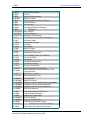
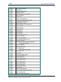
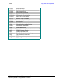
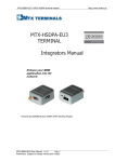
1
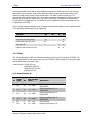
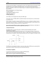
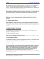
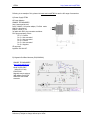
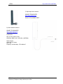
GTR64 http://www.matrix.es/GTR64 GTR-64 TERMINAL Integrators Manual Intelligent, powerful, flexible and simple GSM Terminal in a box Powered by WAVECOM GR64 wireless CPU (legacy SonyEricsson M2M) GTR64 Integrators Manual V.1.2 Pag. 1 Preliminary. Subject to change without prior notice GTR64 http://www.matrix.es/GTR64 Important information This technical description contains important information for start up and use of the GTR64 Terminal. Read it carefully before you start working with the GTR64 Terminal. The warranty will be void should damage occur due to non-compliance with these instructions for use. We cannot accept any responsibility for consequential loss. SECOND EDITION. JULY 2006 Service and Support To contact customer support please use the contact details below: Matrix Electronica Alejandro Sanchez, 109 28019 Madrid –[email protected] Tel. +34915602737 Information about GTR64 product and accessories is available on the following web site: http://www.matrix.es/GTR64 Or contact your local distributor / sales agent: GTR64 Integrators Manual V.1.2 Pag. 2 Preliminary. Subject to change without prior notice GTR64 http://www.matrix.es/GTR64 1. INTRODUCTION ................................................................................................................................................. 5 1.1 Description............................................................................................................................ 5 1.2 Highlights.............................................................................................................................. 6 1.3 GTR-64 Wireless modems in a Communication System.............................................................. 7 1.4 Main Features and Services .................................................................................................... 9 1.4.1 Types of Mobile Station .............................................................................................................................. 9 1.4.2 Short Message Service................................................................................................................................ 9 1.4.3 Voice Calls ................................................................................................................................................. 9 1.4.4 Data .......................................................................................................................................................... 10 1.4.5 GPRS Multi-Slot Support.......................................................................................................................... 10 1.4.6 SIM Card .................................................................................................................................................. 10 1.4.7 Power Consumption ................................................................................................................................. 10 1.5 Precautions ......................................................................................................................... 10 2. MECHANICAL DESCRIPTION ...................................................................................................................... 11 2.1 Overview ............................................................................................................................ 11 2.2. Dimensions ........................................................................................................................ 12 3. ELECTRICAL DESCRIPTION ........................................................................................................................ 12 3. ELECTRICAL DESCRIPTION ........................................................................................................................ 13 3.1 Power Conector ................................................................................................................... 13 3.2 Audio Conector .................................................................................................................... 14 3.3 Mini USB Connector ............................................................................................................. 15 3.4 Antenna Conector ................................................................................................................ 16 3.5. SIM card reader.................................................................................................................. 16 3.6 RS232 Serial Port................................................................................................................. 17 3.6.1 Serial Data ............................................................................................................................................... 18 3.6.2 Serial Data Signals - RD, TD ................................................................................................................... 18 3.6.3 Control Signals - RTS, CTS, DTR, DSR, DCD, RI ................................................................................... 18 3.7 Expansion I/O port............................................................................................................... 19 3.7.1. SECONDARY SERIAL PORT.................................................................................................................. 20 3.7.2. I2C Serial Control Bus ............................................................................................................................ 20 3.7.3. SPI Bus .................................................................................................................................................... 21 3.7.4. General Purpose IO................................................................................................................................. 21 3.7.5 Real Time Clock ....................................................................................................................................... 22 3.8. Software Updates ............................................................................................................... 22 4. OPERATION....................................................................................................................................................... 23 4.1 4.2 4.3 4.4 Switching On the Modem...................................................................................................... 23 Switching Off the Modem ..................................................................................................... 23 Resetting the Modem ........................................................................................................... 23 Operating States/LED........................................................................................................... 23 5. EMBEDDED APPLICATIONS......................................................................................................................... 24 5.1 Features ............................................................................................................................. 24 5.2 Implementation ................................................................................................................... 24 5.2.1 Limitations................................................................................................................................................ 24 5.2.2 M2mpower IDE (Integrated Developers Environment) ........................................................................... 25 6 SAFETY AND PRODUCT CARE...................................................................................................................... 25 6.1. Safety instructions .............................................................................................................. 25 6.2. General precautions ............................................................................................................ 25 GTR64 Integrators Manual V.1.2 Pag. 3 Preliminary. Subject to change without prior notice GTR64 6.3. 6.4. 6.5. 6.6. http://www.matrix.es/GTR64 SIM card precautions .......................................................................................................... 26 Antenna precautions ........................................................................................................... 26 Radio Frequency (RF) exposure and SAR .............................................................................. 26 Personal Medical Devices..................................................................................................... 27 7. INSTALLATION OF THE MODEM ............................................................................................................... 27 7.1 Where to install the modem.................................................................................................. 27 7.1.1 Environmental conditions......................................................................................................................... 27 7.1.2 Signal strength.......................................................................................................................................... 27 7.1.3 Connections of components to GTR64 Terminal...................................................................................... 28 7.1.4 Network and Subscription ........................................................................................................................ 28 7.2 How to install the modem..................................................................................................... 28 7.2.1 Power supply ............................................................................................................................................ 28 7.2.2 Securing the modem ................................................................................................................................. 28 7.3 Antenna .............................................................................................................................. 28 7.3.1 General..................................................................................................................................................... 28 7.3.2 Antenna type ............................................................................................................................................. 29 7.3.3 Antenna placement ................................................................................................................................... 29 7.3.4 The antenna cable..................................................................................................................................... 29 7.3.5 Possible communications disturbances .................................................................................................... 29 7.4 Accessories ......................................................................................................................... 29 8. DISPOSAL OF OLD ELECTRICAL & ELECTRONIC EQUIPMENT (WEEE MARK) ......................... 33 9. ABBREVIATIONS ............................................................................................................................................. 33 10. AT COMMAND SUMMARY .......................................................................................................................... 34 GTR64 Integrators Manual V.1.2 Pag. 4 Preliminary. Subject to change without prior notice GTR64 http://www.matrix.es/GTR64 1. INTRODUCTION 1.1 Description The GTR64 is an intelligent GSM/GPRS control terminal that encapsulates everything you need for wireless M2M capability in one compact unit. In conjunction with M2mpower package the GTR64 can host and control your wireless application, minimising the need for extra components. Alternatively, it can be used as a powerful standalone GPRS modem with its intrinsic TCP/IP stack. The GTR64 is a self contained terminal with its own SIM card reader and two standard connectors interfaces, minimising the need for further hardware development.. This terminal can be used as a powerful and flexible device that can be used in a wide range of telemetry and telematics applications that rely on the remote exchange of data, voice, SMS or faxes via the GSM cellular network. As well as providing a standard RS232 serial communication interface the GTR64 also has an audio interface allowing an analogue handset to be connected. Also a USB port is included to allows the connectivity to all relevant PCs and control boards in office and industrial environments. The expansion port has a wide and useful range of IOs that can be reconfigured to add functions and features that make your M2M solution both innovative and cost effective. The GTR64 can be used to provide a communications link for a variety of wireless applications including fleet and asset management, vending, security and alarm monitoring, e-maintenance and other telemetry applications. With quad band 900/1800 MHz and 850/1900 MHz, your applications can be used all over the world. The control terminal comes with a library of sample script applications to give developers a head start where needed. The GTR-64 incorporates a Wavecom (legacy Sony Ericsson) GR64/40 GSM/GPRS wireless CPU engine. The GTR64 terminal offers compatibility with both SonyEricsson legacy GM28/29 and GT47/48 terminals, with enhanced features. Note!.All functions described inside this Technical Description are only possible when the SIM-Card is inserted GTR64 Integrators Manual V.1.2 Pag. 5 Preliminary. Subject to change without prior notice GTR64 http://www.matrix.es/GTR64 1.2 Highlights Radio Features Quad Band GSM/GPRS GSM 850/900 Power class 4 (33dBm) GSM 1800/1900 Power class 1 (30dBm) Mobile Class B Extended Measurement Reporting Compliant with 3GPP Release 99 Protocol Stack Interfaces RS232 9–way Dsub Expansion Port: 15-way HD-Dsub: 4 Digital Input/Output 1 Analog Input 1 I2C bus 1 2-wires RS232 UART VRTC + Alarm USB mini (2.0 Full-Speed End-Point Compliant) Power: 5 – 32VDC (RJ11) Audio: Handset (RJ9) Antenna: 50 Ohms (FME male) SIM card reader: 1,8V/3V interface with SIM detection General Features Power supply: 5 – 32 VDC Overall dimensions (excluding connectors): 77 x 67 x 26 mm Temperature range: -30°C to +75°C (Operational) -40°C to +85°C (Storage temperature) Weight: ca. 100g Control by AT commands (GSM 27.005, 27.007 plus proprietary commands) Data Features GPRS Class 10 Multiple simultaneous PDDP contexts GPRS Coding Schemes CS1-CS4 Transparent and non-transparent CSD up to 9.6 kbps Modem Type; V21, V22, V23, V22bis, V26ter, V32, V34, V24 V42bis compression GSM supplementary services supported GSM 27.010 Multiplexing Protocol USSD GTR64 Integrators Manual V.1.2 Pag. 6 Preliminary. Subject to change without prior notice GTR64 http://www.matrix.es/GTR64 Voice Features Telephony Emergency calls Full Rate, Enhanced Full Rate, Half Rate and Adaptive Multi-rate (FR/EFR/HR/AMR) Noise suppression and echo cancellation Sidetone/microphone amplification Short Message Service (SMS) Features Text and PDU Point to point (MT/MO) Cell Broadcast Internet Protocols TCP/UDP/IP protocol stack Extensive AT command access to TCP/IP stack Multi sockets (up to 15) through AT commands Non blocking listening/server capability IPv4 protocol Dynamic & static IP address allocation PPP protocol (PAP) Embedded Application Multiple UART access Embedded script interpreter Extensive API library Embedded application script downloads over the air using GPRS 1.3 GTR-64 Wireless modems in a Communication System Figure 1 and Figure 2 illustrate the main blocks of a wireless communication system using the wireless modem. Figure 1 shows the communication system when a micro-controller is used. They also show the communication principles of the system and the interface between the wireless modem and the application and Figure 2 shows the communication system when the script is embedded on the wireless modem. The definitions in the figures, as used elsewhere in this manual, are in accordance with the recommendations of 3GPP TS 27.007. The MS (mobile station) represents the wireless modem and SIM card. The wireless modem excluding SIM card, is known as the ME (mobile equipment). The DTE (data terminal equipment) is the controlling application. This can be either an external host or an internal embedded application. The DCE (data circuit terminating equipment) is the serial communication interface of the MS. GTR64 Integrators Manual V.1.2 Pag. 7 Preliminary. Subject to change without prior notice GTR64 http://www.matrix.es/GTR64 Figure 1. Main Blocks in a Wireless System (external micro-controller) Figure 2. Main Blocks in a Wireless System (embedded application) GTR64 Integrators Manual V.1.2 Pag. 8 Preliminary. Subject to change without prior notice GTR64 http://www.matrix.es/GTR64 1.4 Main Features and Services The GTR64 performs a set of telecom services (TS) according to GSM standard phase 2+, ETSI and ITUT. The services and functions of the GTR64 are implemented by issuing customised applications embedded on the device, or by AT commands issued internally, or over the RS232 serial interface. 1.4.1 Types of Mobile Station The GTR64 is a a fully Quad Band capable GSM/GPRS mobile station with the characteristics shown in the table below. Feature GSM850 E-GSM900 GSM1800 GSM1900 Tx 824-849 880-915 1710-1785 1850-1910 Rx 869-894 925-960 1805-1880 1930-1990 200kHz 200kHz 200kHz 200kHz Number of channels 124 174 374 299 Number of TD slots 8 8 8 8 Duplex spacing 45MHz 45MHz 95MHz 80MHz GSM power class 4 (2W) 4 (2W) 1 (1W) 1 (1W) Frequency range (MHz) Channel spacing Modulation Receive sensitivity GMSK <-102dBm at antenna connector GPRS multi-slot class Class 10 1.4.2 Short Message Service The wireless modem supports the following SMS services: • Sending; MO (mobile-originated) with both PDU (protocol data unit) and textvmode supported • Receiving; MT (mobile-terminated) with both PDU and text mode supported • CBM (cell broadcast message); a service in which a message is sent to all subscribers located in one or more specific cells in the GSM network (for example, traffic reports) • SMS status report according to 3GPP TS 23.40 The maximum length of a text mode SMS message is 160 characters using 7-bit encoding. The wireless modem supports up to six concatenated messages to extend this function. Concatenation is performed by the host application. 1.4.3 Voice Calls The wireless modem offers the capability of MO (mobile originated) and MT (mobile terminated) voice calls, as well as supporting emergency calls. Multi-party, call waiting and call divert features are available. Some of these features are network operator specific. For the inter-connection of audio, the wireless modem offers balanced analogue input and output lines. The wireless modems support HR, FR, EFR and AMR vocoders. GTR64 Integrators Manual V.1.2 Pag. 9 Preliminary. Subject to change without prior notice GTR64 http://www.matrix.es/GTR64 1.4.4 Data The wireless modem supports the following data protocols: • GPRS (General Packet Radio Service) The wireless modem is a Class B terminal. The wireless modem is GPRS multi-slot class10 (4+2) enabled, capable of receiving at a maximum of four timeslots per frame (down link), and transmitting in two timeslots per frame (up link). See section 1.4.5 for multi-slot allocation by class. • CSD (Circuit Switched Data) The GR64 wireless modem is capable of establishing a CSD communication at 9.6 kbps over the air. 1.4.5 GPRS Multi-Slot Support GSM Multi-slot classes supported by Gx64 devices Maximum slot allocation Multislot Class Downlink Uplink Active 8 4 1 5 Allowable Configuration 1 up; 4 down 1 up; 4 down 10 4 2 5 2 up; 3 down Max data rate 8-12Kbps Send 32-48Kbps Receive 8-12Kbps Send 32-48Kbps Receive 16-24Kbps Send 24-36Kbps Receive 1.4.6 SIM Card The GTR64 supports an external SIM card through the integrated SIM holder. Both 3V and 1.8V SIM technology is supported. Older, 5V SIM technology is not supported. 1.4.7 Power Consumption Feature GSM850 & E-GSM900 GSM1800 & GSM1900 Voice/CSD Data (GPRS) Voice/CSD Data (GPRS) Sleep Mode DRX 8 Idle Mode Transmit Operation 1.6 mA 17 mA 2000 mA 1.6 mA 16 mA 1450 mA The power consumption figures shown represent typical average current for maximum transmitted power, single uplink (transmit) slot, and single downlink (receive) slot. The module will consume more average power in different multi-slot configurations, the worst case being that of two uplink and three downlink slots. 1.5 Precautions The GTR64 as a standalone item is designed for indoor use only. To use outdoors it must be integrated into a weatherproof enclosure. Do not exceed the environmental and electrical limits as specified in “Technical Data”, page 32. GTR64 Integrators Manual V.1.2 Pag. 10 Preliminary. Subject to change without prior notice GTR64 http://www.matrix.es/GTR64 2. MECHANICAL DESCRIPTION 2.1 Overview The pictures below show the mechanical design of the module along with the positions of the different connectors and mounting holes. The module case is made of durable PC/ABS plastic. Figure 3. GTR64 Module viewed from the right side Figure 4. GTR64 Module viewed from the left side GTR64 Integrators Manual V.1.2 Pag. 11 Preliminary. Subject to change without prior notice GTR64 http://www.matrix.es/GTR64 2.2. Dimensions Figure 5. Dimensions of the GTR64 terminal in mm GTR64 Integrators Manual V.1.2 Pag. 12 Preliminary. Subject to change without prior notice GTR64 http://www.matrix.es/GTR64 3. ELECTRICAL DESCRIPTION All electrical connections to the module are protected in compliance with the standard air and contact Electrostatic Discharge (ESD). The module uses the following industry standard connectors: • Sub-D 9 pin female (Main RS232 serial port) • High density 15 pin (Secondary RS232 UART and extended I/O interface) • RJ12 6-way (power supply connector) • RJ9 4-way (handset connector) • SIM card reader • FME male coaxial jack (antenna connector) 3.1 Power Conector An RJ11 6-way connector, as shown and described below, serves means of supplying and controlling d.c. power to the modem. The supply voltage, VCC, required by the modem is in the range 32V d.c. Application of the supply voltage does not switch the modem on. To do so an additional active-high control signal, TO_IN, must applied for > 0.2s. A second active-high control signal, HR_IN, can be used to switch modem off when applied for 1 - 2 seconds, or can be used to perform hardware reset when applied for > 3.5s. TO_IN and HR_IN are referenced to GND (pin 6 on the connector). VCC and GND are reverse polarity and overvoltage protected. PIN: Signal Dir Limits Description 1 2 3 VCC VCHARGE HR_IN Input Input Input 5-32 V DC Positive power input 5 – 36 V 4 TO_IN Input 5 3.6V out Output 6 GND Input Active high control line used to switch off or reset the modem VIH > 5V, VIL < 2V Power off: 1s < t < 2s Hard reset: t > 3.5s Active high control line used to switch on the modem VIH > 5V, VIL < 2V Power on: t > 0.2s 3.6V DC reference signal output. Max 75mA Negative power (ground) input and return path for TO_IN, HR_IN and VCHARGE 5 – 36 V GTR64 Integrators Manual V.1.2 Pag. 13 Preliminary. Subject to change without prior notice GTR64 http://www.matrix.es/GTR64 3.2 Audio Conector A 4-way RJ9 connector, as shown below, allows a telephone handset to be plugged into the modem, giving access to the microphone and earpiece signals. The connector may also be used to drive other analogue audio sub-systems or devices. Although the GTR-64 is pre-configured to work with a range of handsets, the audio interface is flexible and its performance can be configured, using AT commands, to match a particular handset or audio subsystem. 1 2 3 MICN BEARN BEARP 4 MICP Audio signal descriptions are listed below: Pin Signal Dir 1 MICN I 2 BEARN O 3 BEARP O 4 MICP I Description Microphone negative input Earpiece negative output Earpiece positive output Microphone positive input MICP and MICN are balanced differential microphone input signals. These inputs are compatible with an electret microphone. The terminal provides a microphone bias at 2.4V, and can supply at least 1mA of current. Parameter Input voltage full scale Frequency response Conditions Min Typ Max Unit max input gain 14 16 18 mVrms min input gain 45 50 56 mVrms -3dB cut-off 300 3400 Hz 2.64 V Output dc bias level 2.16 2.4 BEARP and BEARN are the speaker output signals. These are differential-mode outputs. With a full-scale PCM input to the CODEC, 0 dB audio output gain setting, and a differential load RL = 30Ω, the output voltage between EARP and EARN is 1.5 V rms. For load resistances less than 30Ω, the full-scale output needs is limited using the modules internal programmable gain attenuator. GTR64 Integrators Manual V.1.2 Pag. 14 Preliminary. Subject to change without prior notice GTR64 http://www.matrix.es/GTR64 The electrical characteristics are given in the table below. Parameter Input voltage full scale Frequency response Conditions Min Typ Max Unit RL = 30Ω 1.34 1.5 1.68 Vrms RL = 16Ω 1.41 Vrms RL = 8Ω 1.24 Vrms -3dB cut-off 300 3400 Hz Analogue audio can be used for various configurations, including a car kit mode, portable hands free and speakerphone (with an additional output gain stage). Five audio profiles are available for GR64 users to configure various modes of operation. Each profile is factory set to represent different modes, typical of general usage. The customer can modify profiles to optimize acoustic performance to their specific application. The analogue inputs and outputs share common uplink and downlink chains which are multiplexed, and selectively switched by the user through AT-commands. There five factory-set audio profiles as follows: • Portable hands free Low-level is recommended. • Handset Low-level is recommended. • Car kit Low-level is recommended. • Speakerphone High-level is recommended. • Headset Low-level or High-level can be used with headset, depending on requirements. Portable hands free is the factory-set default profile. The modification, configuration, manipulation and storage of audio profiles is achieved with the AT*E2EAMS (Audio Profile Modification) and AT*E2APR (Audio Profile). 3.3 Mini USB Connector The USB 2.0 interface allows the connectivity to all relevant PCs and control boards in office and industrial environments. The USB interface is a USB 2.0 full speed interface for AT-C modem functionality between the GTR64 Terminal and e.g. a PC. There is an AT command to enable this functionality. See AT*USB in the GTR64 AT command manual. Also there is available drivers for Windows environment applications. Visit GTR64 web page at: www.matrix.es/GTR64 GTR64 Integrators Manual V.1.2 Pag. 15 Preliminary. Subject to change without prior notice GTR64 http://www.matrix.es/GTR64 3.4 Antenna Conector The antenna connector allows transmission of radio frequency (RF) signals between the modem and an external customer-supplied antenna. The modem is fitted with a 50Ω, FME male coaxial jack. Description of antenna connector parameters Parameter Limit Nominal impedance 50Ω (SWR better than 2.5:1) Output Power Static Sensitivity Watt peak (Class 4) 1 Watt peak (Class 1) Better than –102dBm Better than –102dBm Description Extended GSM900 GSM1800 Extended GSM900 GSM1800 3.5. SIM card reader The GTR64 Terminal is fitted with a SIM card reader designed for 1.8V and 3V SIM cards. It is the flipup type which is lockable in the horizontal position and is accessed through a removable panel as shown below. The full operation of the GTR64 relies on a SIM card being inserted.. Some GTR64 functionality may be lost if you try to operate the control terminal without a SIM card The SIM card reader includes a SIM presence switch. This ensures that when a SIM card is inserted or removed while the GTR64 is turned ON, it will reset. GTR64 Integrators Manual V.1.2 Pag. 16 Preliminary. Subject to change without prior notice GTR64 http://www.matrix.es/GTR64 3.6 RS232 Serial Port The modem supports a standard RS232 serial interface (EIA/TIA 574) via its 9 pin Sub-D connector, shown below. In line with serial communication terminology the GTR64 serial modem should be considered as the data circuit-terminating equipment (DCE) and the external application or computer as the data terminating equipment (DTE). The electrical characteristics of the serial port signals are shown below: Pin Signal Dir Voltage levels 1 DCD O > +4V < –4V Data carrier detect 2 RD O > +4V < –4V Received data 3 TD I > 2V < 0.8V Transmitted data 4 DTR I > 2V < 0.8V Data terminal ready 5 GND - 0V Ground connection 6 DSR O > +4V < –4V Data set ready 7 RTS I > 2V < 0.8V Request to send 8 CTS O 9 RI O > < > < +4V –4V +4V –4V Description Clear to send Ring indicator GTR64 Integrators Manual V.1.2 Pag. 17 Preliminary. Subject to change without prior notice GTR64 http://www.matrix.es/GTR64 3.6.1 Serial Data The modem supports the standard data character format of • 1 start bit, 7 or 8 data bits, 1 optional parity bit, 1 or 2 stop bits • Programmable baud rate • Auto-configuration mode with auto-baud and auto-format operation In line with serial communication terminology the module is the data circuit-terminating equipment (DCE) and the external application or computer is the data terminating equipment (DTE). 3.6.2 Serial Data Signals - RD, TD The default baud rate of the UARTs is auto-baud. Baud rates of between 600 bauds to 460 kbauds are possible. The wireless modem also supports 3GPP TS 27.010 multiplexing protocol, which starts when the appropriate command is sent. Serial Data From Modem (RD) RD is an output signal that the modem uses to send data to the application. Serial Data To Modem (TD) TD is an input signal, used by the application to send data to the modem. 3.6.3 Control Signals - RTS, CTS, DTR, DSR, DCD, RI Depending upon the user application, some, all, or none of the control signals may be needed. Each of the control signals can alternatively be configured as a general purpose IO. When hardware flow control is not used in communications between the application and the wireless modem, some applications may require RTS and CTS to be connected to each other at the wireless modem. Users should familiarize themselves with the specific implementation of their UART. RTS and CTS are capable of transmitting at 1/10th of the data transmission speed for data rates up to 460kbps (byte-oriented flow control mechanism). Request to Send (RTS) Used to condition the DCE for data transmission. The default level is high by internal pull up. The exact behaviour of RTS is defined by an AT command. Software or hardware control can be selected. Hardware flow is the default control. The application must pull RTS low to communicate with the modem. The modem will respond by asserting CTS low, indicating it is ready for communication. Clear To Send (CTS) CTS indicates that the DCE is ready to transmit data. The default level is high. You can define the exact behaviour of CTS through an AT command, and can select software or hardware flow control. Data Terminal Ready (DTR) DTR indicates that the DTE is ready to transmit and receive data. It also acts as a hardware ‘hang-up’, terminating calls when switched high.The signal is active low. You can define the exact behaviour of DTR with an AT command. The DTR line can also be used to switch on the modem when activated for 0.2 seconds. The DTR line must be deactivated prior to switching off the modem to ensure it switches off (powers down) correctly. Data Set Ready (DSR) An active DSR signal is sent from the modem to the application (DTE) to confirm that a communications path has been established. DSR has two modes of operation, settable using the AT command AT&S. GTR64 Integrators Manual V.1.2 Pag. 18 Preliminary. Subject to change without prior notice GTR64 http://www.matrix.es/GTR64 Data Carrier Detect (DCD) DCD indicates that the DCE is receiving a valid carrier (data signal) when low. You can define the exact behaviour of DCD with an AT command. Ring Indicator (RI) RI indicates that a ringing signal is being received by the DCE when low. You can define the exact behaviour or RI with an AT command. 3.7 Expansion I/O port The GTR64 supports a range of configurable I/Os including a second 2-wire RS232 interface. on the 15 pin high density connector together with I2C bus and VTRC with ALARM functionality. 1. SCL 2. RD3 6. SDA 7. VRTC 11. IO 2 12. IO 4 3. TD3 4. IO 1 5. IO 3 8. ALARM 9. VREF 10. RI / IO8 13. SERVICE 14. GND 15. ADC 1 Pin GTR64 Signal Dir Max. Voltage limits 1 SCL O -0.5 - +3.6 V 2 RD3 I ±5 v Secondary RS232 UART signal: Transmitted data 3 TD3 ± 25V Secondary RS232 UART signal Received data. V IL < 0.6V, V IH > 2.4V 4 IO 1 I/O -0.5 - VREF 5 IO 3 I/O -0.5 - VREF 6 SDA I/O -0.5 - +3.6 V 7 VRTC I 1,1 – 1,55 V 8 ALARM O -0.5 - +3.6V 9 VREF O +3.6 V Description I2C clock signal Digital input/output I/O 1 Digital VREF Digital input/output I/O 3 Digital VREF I2C data VRTC supply for real time clock RTC Alarm LEAVE UNCONNECTED !!! GTR64 Integrators Manual V.1.2 Pag. 19 Preliminary. Subject to change without prior notice GTR64 http://www.matrix.es/GTR64 10 RI1 IO 8 O I/O 0.4 – 3.2 V -0.5 - VREF Ring Indication Digital Input/Output I/O 8 11 IO 2 I/O -0.5 - VREF Digital Input/Output I/O 3 Digital VREF 12 IO 4 I/O -0.5 - VREF Digital Input/Output I/O 4 Digital VREF 13 SERVICE I -0.5 - +3.6V Flash programming enable signal Active High 14 GND 0V Ground connection 15 ADC 1 0 - 2.59V ADC Input 1 I 3.7.1. SECONDARY SERIAL PORT The secondary serial port is called UART3. Pin Name Direction Function 2 RD3 I ±5 v 3 TD3 o ± 25V Secondary RS232 UART signal: Transmitted data Secondary RS232 UART signal Received data. V IL < 0.6V, V IH > 2.4V UART 3 consists of a full duplex serial communication port with transmission and reception lines. Timing and electrical signals characteristics are the same as for UART1, including the baud rate range and the capability to auto-baud. 3.7.2. I2C Serial Control Bus Because of the nature of the I2C interface signals, SDA (data) & SCL (clock), they utilize a different type of level-shifting technology to that of the ‘common’ IO. The I2C level shifter IC uses an open drain construction with no direction pin, ideally suited to bi-directional low voltage I2C port translation to the normal 3.3 V or 5.0 V I2C-bus signal levels. Unlike the common level shifters, the I2C level shifters have a very low (6.5ohm RDSON) resistance between input and output pins. The I2C level shifters use VREF as the host-side voltage reference and the internal 1.8V digital IO core as the module-side reference. The I2C interface comprises two signals; data (SDA) and clock (SCL). Both SDA and SCL have pull-up resistors. Therefore, when the bus is free, both SDA and SCL are in a HIGH state. The GTR64 implementation of I2C supports only a single master mode, with the module being the master. The output stages of SDA and SCL must have an opendrain or open-collector to perform a wired-AND function. The wired-AND function provides the I2C bus ability to perform clock synchronization on the SCL line. Due to the wired-AND function, the SCL line will be held LOW by the device with the longest LOW period. Therefore, the device with the shorter LOW period will be in a HIGH wait-state during this time. GTR64 Integrators Manual V.1.2 Pag. 20 Preliminary. Subject to change without prior notice GTR64 http://www.matrix.es/GTR64 Clock synchronization can be used as a handshaking mechanism, to enable receivers to cope with fast data transfers. On a byte level, a slave (host application-side) I2C device may be able receive a data transfer, but need time to store the byte received before it is ready to receive another byte. The slave/receiver will therefore hold the SCL line low, after sending the acknowledge bit following the byte received, thereby forcing the master into a wait state. Once the SCL is released by the slave/receiver, the wait state of the master will end. This feature of the I2C standard is known as clock-stretching and is supported by the GTR64. The I2C interface supports Standard-mode (100kbps) and Fast-mode (400kbps). It also supports Normal (7-bit) addressing and Extended (10-bit) addressing . Parameter Min Typ SCL clock frequency 0 LOW period of the SCL clock 1.3 μs HIGH period of the SCL clock 0.6 μs Data hold time 0 Capacitive load for each bus line Max Unit 400 kHz 0.9 μs 400 pF 3.7.3. SPI Bus SPI: The implementation of SPI uses the same command structure as the AT command AT*E2SPI. The current implementation of this function only supports SPI Mode 0 (data is latched on a rising clock edge and the default state of the clock is low). 4 wires are used - CLOCK (IO1 pin), DATA INPUT (IO2 pin), DATA OUTPUT (IO3 pin), and SYNC (RI pin). 3.7.4. General Purpose IO Pin GTR64 Signal Dir Max. Voltage limits 4 IO 1 I/O -0.5 - VREF 11 IO 2 I/O -0.5 - VREF 5 IO 3 I/O -0.5 - VREF 12 IO 4 I/O -0.5 - VREF Digital Input/Output I/O 4 Digital VREF 10 RI1 IO 8 O I/O 0.4 – 3.2 V -0.5 - VREF Ring Indication Digital Input/Output I/O 8 Description Digital Digital Digital Digital Digital Digital Input/Output I/O 1 VREF Input/Output I/O 2 VREF Input/Output I/O 3 VREF GTR64 Integrators Manual V.1.2 Pag. 21 Preliminary. Subject to change without prior notice GTR64 http://www.matrix.es/GTR64 All general purpose IO (GPIO) is programmable by the user. The I/O8 has alternate functionality already associated with it; this is indicated in the default column. This I/O which has alternate function is effectively multiplexed, so that the user chooses through AT commands the appropriate configuration for their application. GPIO is programmable for the following features: • An input or output • Level-sensitive or transition-sensitive • Open drain or direct drive • Polarity (inversion) • Internal pull-up resistors In the GTR64, all IO undergoes level shifting with VREF signal. In the actual version of GTR64, VREF is connected internally to 3.6V internal VCC, so the level values are referred to 3.6V. Only by request, is it possible to change the VREF acting as an input, providing the reference input to the host side level shifter devices. This enables users of varying technologies to connect directly to the GR64’s IO by providing a reference from their own application IO. Users should not that GPIO that is used truly bidirectional cannot be open drain type on both sides. At least one side needs to be able to drive the signal both high and low. 3.7.5 Real Time Clock The GTR64 contains a real time clock (RTC) to maintain accurate timekeeping and to enable “timestamping” of messages. The RTC is powered with the signal VRTC present in pin 7 of the expansion conector. The user must connect this pin to an external energy device like a battery or super-capacitor to provide back-up power to maintain the RTC. Example. If using a 300mF supercap the RTC can be maintain for at least 12 hours. The GTR64 can accommodate this battery or super-cap inside, and the GTR64 can be ordered with this special option by request. Please contact your sales nearest distributor. 3.8. Software Updates It is possible and sometimes necessary to update the GTR64 software. Updates must be carried out by a approved technician. Please contact your supplier for details Service/Programming GTR64 Integrators Manual V.1.2 Pag. 22 Preliminary. Subject to change without prior notice GTR64 http://www.matrix.es/GTR64 SERVICE Input Flash programming enable signal The SERVICE input signal is for flash programming enable input. The SERVICE pin is driven active high by the host application using either a logic control input or applying a dc voltage (common in legacy applications) to begin a flash download. This pin should be pulled leave unconnected during normal use Signal SERVICE Mode Active High Inactive Low Value Minimum input voltage 2.5 V Maximum input voltage 12.0 V Maximum input voltage 0.8 V 4. OPERATION 4.1 Switching On the Modem There are two ways to switch on the modem, once power is applied. • either assert TO_IN high for > 0.2s; • or activate the RS232 control line DTR, high for > 0.2s. The modem is fully operational after 4 seconds. Logging onto a network may take longer than this and is outside the control of the modem. The modem can be configured to start up at the time power is applied by permanently tying power connector signals TO_IN (pin 4) and VCC (pin 1) together. In this case DTR must be used to switch the modem on again after it has been switched off or reset, while power is still applied. Note! DTR must be cycled from low to high. 4.2 Switching Off the Modem There are three ways to switch off (power down) the modem as described below: • either use the AT+CFUN command; • or assert HR_IN high for 1 - 2 seconds. A delay of up to 10s is experienced as the modem logs off the network • or assert TO_IN low to high for 1 - 2 seconds. Note! The DTR line must be deactivated prior to switching off the modem to ensure the unit switches off correctly. 4.3 Resetting the Modem A full system reset, independent of the status of the software, may be applied to the modem as follows: • assert HR_IN high for > 3.5s. 4.4 Operating States/LED The modem has a green LED, as depicted below, which is used to indicate various operating states. These states are described in following table. GTR64 Integrators Manual V.1.2 Pag. 23 Preliminary. Subject to change without prior notice GTR64 http://www.matrix.es/GTR64 Operating State LED Status After switching on the modem On after 4s Switch off (Power down) or power removed Off Standby or talk Flashing No network, network search, no SIM card, no PIN entered On Notes! Switch off (Power Down): DC power is applied but the modem is switched OFF. Standby: The GTR64 is switched ON and camped on to the network. No call in progress. Talk: The GTR64 is switched ON and a voice/data call is in progress. 5. EMBEDDED APPLICATIONS The module has the capability to store and run customer written code in the form of a script during the processors idle time, through the use of an on board interpreter. 5.1 Features Main features of embedded applications are as follows. •C based scripting language (Sony Ericsson specific) •Over the air upgrade of scripts (NOT GSM software) •Library of intrinsic functions •Multiple on radio device script support 5.2 Implementation The module has up to 512kbytes of space available for storage of two scripts in the scripting language and 256kbytes of operating RAM. Structures included in this language are: •If - then - else statements •While loops •For loops All hardware interfaces that are normally available to the module through the AT commands are available to the embedded application. Further drivers have been written such as M bus and I2C for use by the embedded application (EA) through the use of the I/O pins. 5.2.1 Limitations Since the module is processing the script using its own memory, limitations are placed onto the scripts that are run. A direct comparison cannot be made to a fully compiled C program in terms of size but a gauge of script size is that if each line were 128 characters long in the script then the script could be 350 lines long. Processing power is something that needs to be considered as the script is run as a low priority process within the software. However, controller mode stops GSM operation and provides all the processing power for the script to be run. See the Application Guide for more details. GTR64 Integrators Manual V.1.2 Pag. 24 Preliminary. Subject to change without prior notice GTR64 http://www.matrix.es/GTR64 Code cannot be ported directly from an existing application and loaded directly onto the radio device. It must be re written in the Sony Ericsson Mobile script language so that the radio device interpreter can function correctly. 5.2.2 M2mpower IDE (Integrated Developers Environment) The IDE is a windows based package which allows the user to write, simulate, debug and download the application into a radio device with the embedded application (EA) software. The standard version is designed to run on Windows XP and 2000. A guide is available for implementing applications using the developers kit and the embedded application (EA) functionality. For further information please contact your customer support. 6 SAFETY AND PRODUCT CARE Please read the information in this section and the information in “Installation of the Modem”, before starting your integration work! 6.1. Safety instructions PLEASE READ THESE SAFETY INSTRUCTIONS AND KEEP A COPY OF THEM. • Always ensure that use of the modem is permitted. The modem may present a hazard if used in proximity to personal medical electronic devices. As a rule, the modem must not be used in hospitals, airports or planes. • Never use the modem at a gas station, refuelling point, blasting area or in any other environment where explosives may be present. • Operating the modem close to other electronic devices, such as antennas, television sets, and radios may cause electromagnetic interference. • This product is intended to be used with the antenna or other radiating element at least 20cm away from any part of the human body. In applications where this rule cannot be applied, the application designer is responsible for providing the SAR measurement test report and declaration. • You are responsible for observing your country's safety standards, and where applicable, the relevant wiring rules. 6.2. General precautions The GTR64 Terminal as a stand alone item is designed for indoor use only. To use outside it must be integrated into a weatherproof enclosure. Do not exceed the environmental and electrical limits as specified in “Technical Data”. • Avoid exposing the modem to lighted cigarettes, naked flames or to extreme hot or cold temperature. • Never try to dismantle the modem yourself. There are no components inside the modem that can be serviced by the user. If you attempt to dismantle the modem, you may invalidate the warranty. GTR64 Integrators Manual V.1.2 Pag. 25 Preliminary. Subject to change without prior notice GTR64 http://www.matrix.es/GTR64 • The GTR64 Terminal must not be installed or located where the surface temperature of the plastic case may exceed 85°C. • All cables connected to the GTR64 Terminal must be secured or clamped, immediately adjacent to the modem's connectors, to provide strain relief and to avoid transmitting excessive vibration to the modem in the installation • Ensure the d.c. cable, supplying power to the GTR64 Terminal, does not exceed 3 metres. • To protect power supply cables and meet the fire safety requirements when the unit is powered from a battery or a high current supply, connect a fast 1.25A fuse in line with the positive supply. • Do not connect any incompatible component or product to the GTR64 Terminal. Note! GTR64 distribuitors and sales offices may refuse warranty claims where evidence of product misuse is found. 6.3. SIM card precautions Before handling the SIM card in your application, ensure that you are not charged with static electricity. Use proper precautions to avoid electrostatic discharges. • When the SIM card hatch is opened, the SIM card connectors lie exposed under the SIM card holder. Caution! Do not touch these connectors! If you do, you may release an electrical discharge that could damage the modem or the SIM card. • When designing your application, the SIM card’s accessibility should be taken into account. We always recommend that you have the SIM card protected by a PIN code. This will ensure that the SIM card cannot be used by an unauthorized person. 6.4. Antenna precautions If the antenna is to be mounted outside, consider the risk of lightning. Follow the instructions provided by the antenna manufacturer. • Never connect more than one modem to a single antenna. The modem can be damaged by radio frequency energy from the transmitter of another modem. • Like any mobile station, the antenna of the modem emits radio frequency energy. To avoid EMI (electromagnetic interference), you must determine whether the application itself, or equipment in the application’s proximity, needs further protection against radio emission and the disturbances it might cause. Protection is secured either by shielding the surrounding electronics or by moving the antenna away from the electronics and the external signals cable. • The modem and antenna may be damaged if either come into contact with ground potentials other than the one in your application. Beware, ground potential are not always what they appear to be. 6.5. Radio Frequency (RF) exposure and SAR Your wireless modem device is a low-power radio transmitter and receiver (transceiver). When it is turned on, it emits low levels of radio frequency energy (also known as radio waves or radio frequency fields). Governments around the world have adopted comprehensive international safety guidelines, developed by scientific organizations, e.g. ICNIRP (International Commission on Non-Ionizing Radiation Protection) and GTR64 Integrators Manual V.1.2 Pag. 26 Preliminary. Subject to change without prior notice GTR64 http://www.matrix.es/GTR64 IEEE (The Institute of Electrical and Electronics Engineers Inc.), through periodic and thorough evaluation of scientific studies. These guidelines establish permitted levels of radio wave exposure for the general population. The levels include a safety margin designed to assure the safety of all persons, regardless of age and health, and to account for any variations in measurements. Specific Absorption Rate (SAR) is the unit of measurement for the amount of radio frequency energy absorbed by the body when using a transceiver. The SAR value is determined at the highest certified power level in laboratory conditions, but the actual SAR level of the transceiver while operating can be well below this value. This is because the transceiver is designed to use the minimum power required to reach the network. The GR64 wireless modem device has been approved for applications where the antenna is located >20cm from the body. In all other configurations the integrator is responsible for meeting the local SAR regulations. Integrators of the GR64 wireless modem device are responsible for ensuring that they meet the SAR regulatory requirements of the countries in which they intend to operate the device, and that their documentation contains the relevant SAR declaration, certification information, and user guidance as appropriate. 6.6. Personal Medical Devices Wireless modem devices may affect the operation of cardiac pacemakers, hearing aids and certain other implanted equipment. If a minimum distance of 15 cm (6 inches) is maintained between the GR64 module’s radiating antenna and a pacemaker, the risk of interference is limited. If the integrator’s application is likely to be situated in the vicinity of personnel, a suitable warning should be contained in the equipment manual to this effect. 7. INSTALLATION OF THE MODEM This chapter gives you advice and helpful hints on how to integrate the GTR64 Terminal into your application from a hardware perspective. 7.1 Where to install the modem There are several conditions which need to be taken into consideration when designing your application as they might affect the modem and its function. They are: 7.1.1 Environmental conditions The modem must be installed so that the environmental conditions stated in the Technical Data chapter, such as temperature, humidity and vibration are satisfied. Additionally, the electrical specifications in the Technical Data section must not be exceeded. 7.1.2 Signal strength The modem has to be placed in a way that ensures sufficient signal strength. To improve signal strength, the antenna can be moved to another position. Signal strength may depend on how close the modem is to a radio base station. You must ensure that the location at which you intend to use the modem, is within the network coverage area. Degradation in signal strength can be the result of a disturbance from another source, for example an electronic device in the immediate vicinity. More information about possible communication disturbances can be found in section 7.3.5. When an application is completed, you can verify signal strength by issuing the AT command AT+CSQ. See “AT+CSQ Signal Strength”. GTR64 Integrators Manual V.1.2 Pag. 27 Preliminary. Subject to change without prior notice GTR64 http://www.matrix.es/GTR64 Tip! Before installing the modem, use an ordinary mobile telephone to check a possible location for it. In determining the location for the modem and antenna, you should consider signal strength as well as cable length. 7.1.3 Connections of components to GTR64 Terminal The integrator is responsible for the final integrated system. Incorrectly designed or installed, external components may cause radiation limits to be exceeded. For instance, improperly made connections or improperly installed antennas can disturb the network and lead to malfunctions in the modem or equipment. 7.1.4 Network and Subscription Before your application is used, you must ensure that your chosen network provides the necessary telecommunication services. Contact your service provider to obtain the necessary information. • If you intend to use SMS in the application, ensure this is included in your (voice) subscription. • Consider the choice of the supplementary services 7.2 How to install the modem 7.2.1 Power supply • Use a high-quality power supply cable with low resistance. This ensures that the voltages at the connector pins are within the allowed range, even during the maximum peak current. • When the unit is powered from a battery or a high current supply, connect a fast 1.25A fuse in line with the positive supply. This protects the power cabling and modem. 7.2.2 Securing the modem Before securing the modem take into account the amount of additional space required for the mating connectors and cables that will be used in the application. • Where access is restricted, it may be easier to connect all the cables to the modem prior to securing it in the application. • Securely attach the GTR64 Terminal modem to the host application using two 3mm diameter pan-head screws 7.3 Antenna 7.3.1 General The antenna is the component in your system that maintains the radio link between the network and the modem. Since the antenna transmits and receives electromagnetic energy, its efficient function will depend on: • the type of antenna (for example, circular or directional); • the placement of the antenna; • communication disturbances in the vicinity in which the antenna operates. In the sections below, issues concerning antenna type, antenna placement, antenna cable, and possible communication disturbances are addressed. In any event, you should contact your local antenna manufacturer for additional information concerning antenna type, cables, connectors, antenna placement, and the surrounding area. You should also determine whether the antenna needs to be grounded or not. Your local antenna manufacturer might be able to design a special antenna suitable for your the application. GTR64 Integrators Manual V.1.2 Pag. 28 Preliminary. Subject to change without prior notice GTR64 http://www.matrix.es/GTR64 7.3.2 Antenna type Make sure that you choose the right type of antenna for the modem. Consider the following requirements: • the antenna must be designed for the one of the frequency bands in use; please ask your network provider for more informations: • GSM 850/900 MHz • GSM 1800/1900 MHz; • the impedance of the antenna and antenna cable must be 50Ω; • the antenna output-power handling must be a minimum of 2W; • the VSWR value should be less than 3:1 to avoid damage to the modem. 7.3.3 Antenna placement The antenna should be placed away from electronic devices or other antennas. The recommended minimum distance between adjacent antennas, operating in a similar radio frequency band, is at least 50cm. If signal strength is weak, it is useful to face a directional antenna at the closest radio base station. This can increase the strength of the signal received by the modem. The modem’s peak output power can reach 2W. RF field strength varies with antenna type and distance. At 10cm from the antenna the field strength may be up to 70V/m and at 1m it will have reduced to 7V/m. In general, CE-marked products for residential and commercial areas, and light industry can withstand a minimum of 3V/m. 7.3.4 The antenna cable Use 50Ω impedance low-loss cable and high-quality 50Ω impedance connectors (frequency range up to 2GHz) to avoid RF losses. Ensure that the antenna cable is as short as possible. The Voltage StandingWave Ratio (VSWR) may depend on the effectiveness of the antenna, cable and connectors. In addition, if you use an adapter between the antenna cable and the antenna connector, it is crucial that the antenna cable is a high-quality, low-loss cable. Minimize the use of extension cables, connectors and adapters. Each additional cable, connector or adapter causes a loss of signal power. 7.3.5 Possible communications disturbances Possible communication disturbances include the following: • Noise can be caused by electronic devices and radio transmitters. • Path-loss occurs as the strength of the received signal steadily decreases in proportion to the distance from the transmitter. • Shadowing is a form of environmental attenuation of radio signals caused by hills, buildings, trees or even vehicles. This can be a particular problem inside buildings, especially if the walls are thick and reinforced. • Multi-path fading is a sudden decrease or increase in the signal strength. This is the result of interference caused when direct and reflected signals reach the antenna simultaneously. Surfaces such as buildings, streets, vehicles, etc., can reflect signals. • Hand-over occurs as you move from one cell to another in the GSM network. Your mobile application call is transferred from one cell to the next. Hand-over can briefly interfere with communication and may cause a delay, or at worst, a disruption. 7.4 Accessories The GTR64 has been type approved together with a range of accessories including: Power supply, all type of antennas (indoor, outdoor, high gain, etc…), cables and DIN adapter GTR64 Integrators Manual V.1.2 Pag. 29 Preliminary. Subject to change without prior notice GTR64 http://www.matrix.es/GTR64 Following is an example of this, please visit www.matrix.es/GTR64 to see the full-range of accessories A) Power Supply GTR64 AC Power Adaptor: OPANIEL TECHNOLOGIES http://www.opaniel.com/ Input: 240VAC, 0.1A power adaptor, 50-60Hz mains lead Euro plug option. Output: 12V DC, 1.2A. 2m cable with RJ12 plug connector see below. RJ12 plug proprietary pinout: Pin 1 = Positive Pin 2 = Not connected Pin 3 = Not connected Pin 4 = Positive Pin 5 = Not connected Pin 6 = Negative CE approved logicode: 901.004.167. B) Magnetic Dual Band Antenna (900/1800MHz) OPANIEL TECHNOLOGIES http://www.opaniel.com Model # MTX-FME F ( whips 6 & 22 cm) 118.003.000 Magnetic-mount antenna, 0dB radiator, 3m RG174 cable with FME female connector GTR64 Integrators Manual V.1.2 Pag. 30 Preliminary. Subject to change without prior notice GTR64 http://www.matrix.es/GTR64 C) Right angle short antenna OPANIEL TECHNOLOGIES http://www.opaniel.com Model # MTX-ACODADA FME F D) Patch Adeshive Antenna OPANIEL TECHNOLOGIES http://www.opaniel.com MTX-UT902 – FME F 118.003.024 MTX- UT-902, RG174 3 mts, GSM DUAL BAND ( 900 / 1800 MHz ) ANTENNA Patch Antenna Cable RG174 3 Meters Gain 2 dB Frequency: 824-960 MHz, 1770-1880mhZ GTR64 Integrators Manual V.1.2 Pag. 31 Preliminary. Subject to change without prior notice GTR64 http://www.matrix.es/GTR64 C) Expansion port - RS232 2-way Serial Cable Modem and System Breakout Cable 1m lead length with: • HD15 male connector Connected to; • DB9 female connector (9 signal RS232 serial connection) • 7 flying leads Conductor current rating < 1.5A DC, 26 AWG HD15 male 1 2 3 4 5 6 7 8 9 10 11 12 13 14 15 DB9 female SCL RD3 TD3 IO 1 IO 3 SDA VRTC ALARM VREF RI1/IO8 IO 2 IO 4 SERVICE GND ADC 1 Flying leads 1 2 3 6 7 8 9 4 5 Black Brown Red Orange Yellow Green Blue Interconnect Table GTR64 Integrators Manual V.1.2 Pag. 32 Preliminary. Subject to change without prior notice GTR64 http://www.matrix.es/GTR64 8. DISPOSAL OF OLD ELECTRICAL & ELECTRONIC EQUIPMENT (WEEE MARK) This symbol, applied on our products and/or on its packaging, indicates that this product should not be treated as household waste when you wish to dispose of it. Instead, it should be handed over to an applicable collection point for the recycling of electrical and electronic equipment. By ensuring this product is disposed of correctly, you will help prevent potential negative consequences to the environment and human health, which could otherwise be caused by inappropriate disposal of this product. The recycling of materials will help to conserve natural resources. For more detailed information about the recycling of this product, please contact your local city office, household waste disposal service or the retail store where you purchased this product. 9. ABBREVIATIONS Abbreviation CBM CBS CSD DCE DTE DTMF EFR EMC ETSI FR GPRS GSM HR HSCSD ITU-T ME MO MS MT PDU RLP RF RTC SIM SMS TA TE TS Explanations Cell Broadcast Message Cell Broadcast Service Circuit Switched Data Data Circuit Terminating Equipment Data Terminal Equipment Dual Tone Multi Frequency Enhanced Full Rate Electro-Magnetic Compatibility European Telecommunication Standards Institute Full Rate General Packet Radio Service Global System for Mobile Communication Half Rate High Speed Circuit Switched Data International Telecommunication Union - Telecommunications Standardisation Sector Mobile Equipment Mobile Originated Mobile Station Mobile Terminated Protocol Data Unit Radio Link Protocol Radio Frequency Real Time Clock Subscriber Identity Module Short Message Service Terminal Adapter Terminal Equipment Telecom Services GTR64 Integrators Manual V.1.2 Pag. 33 Preliminary. Subject to change without prior notice GTR64 http://www.matrix.es/GTR64 10. AT COMMAND SUMMARY The AT standard is a line-oriented command language. AT is an abbreviation of ATtention and it is always used to start sending a command line from the terminal equipment (TE) to the terminal adaptor (TA). The command line consists of a string of alphanumeric characters. It is sent to the GTR64 to instruct it to perform the commands specified by the characters. The AT commands listed below are supported by the GR64(italic) within the GTR64. The AT command user manual can be download from GTR64 web page: www.matrix.es/gtr64. will be same document as GR64 AT command manual. Be aware that not all AT commands will perform valid operations in the GR64 owing to its modified range of IOs. AT command *E2OTR *E2SDR *ECAV *EPEV *ESTKCALL *ESTKCC *ESTKCLOSE *ESTKDISP *ESTKGIN *ESTKITEM *ESTKKEY *ESTKOPEN *ESTKRCVD *ESTKRSH *ESTKSMENU *ESTKSMS *ESTKSNDD *ESTKSS *ESTKTONE *ESTKUSSD AT&C AT&D AT&F AT&S AT&V AT&W AT&Y AT*E2APC AT*E2APD AT* AT*E2CD AT*E2CMGA Description Operational Temperature Range Reporting SIM Detection Unsolicited Response Call Monitoring Unsolicited Result Code Pin Event Unsolicited report Set Up Call Call Control Event From SIM/USIM Application Toolkit Close Channel Display Text Get Input Select Item Get Inkey Open Channel Receive Data Refresh Set Up Menu Send Short Message Send Data Send SS Play Tone Send USSD Circuit 109 (DCD) Control Circuit 108 (DTR) Response Set to Factory Defined Configuration Circuit 107 (DSR) Response View Configuration Profile Store User Profile Select Default User Profile Application Program Control Application Program Download E2APR Audio Profile Manipulation Cell Description Modify message attribute GTR64 Integrators Manual V.1.2 Pag. 34 Preliminary. Subject to change without prior notice GTR64 AT*E2CMGL AT*E2CMGR AT*E2EAMS AT*E2EMM AT*E2ESC AT*E2GAA AT*E2GC AT*E2GDV AT*E2IO AT*E2IPA AT*E2IPACT AT*E2IPATO AT*E2IPC IP AT*E2IPE IP AT*E2IPEV IP AT*E2IPI IP AT*E2IPL IP AT*E2IPO IP AT*E2IPRH AT*E2IPS IP AT*E2OTR AT*E2RESET AT*E2RS232 AT*E2SDR AT*E2SMSRI AT*E2SPN AT*E2SSCS _ AT*E2SSN AT*E2STKTO AT*EALS AT*EAUD AT*EBATTCNF AT*EBSE AT*ECAM AT*ECIND AT*ECLCC AT*ECSP AT*EDRX AT*EDST AT*EIDSUM AT*ELIN AT*EMBOX AT*EMIC AT*EMRDY AT*EMWI http://www.matrix.es/GTR64 List message, without marking message Read Read Message without Read mark Audio Profile Modification Engineering Monitoring Mode Escape Sequence Guard Time GPRS Auto Attach Setting GPRS Class Setting GPRS Data Volume Input/Output Read/Write IP Activate IP Socket Accept IP Socket ATO Command Socket Close Error Socket Events Info listen (server) Open/Connect IP Resolve Host Setup IP Parameters Operational Temperature Reporting Restart Module RS232 control mode SIM Detection Reporting Ring indicator for SMS Service Provider Name Supported Speech Codec Set SIM Serial Number SIM Application Toolkit Settings Request ALS Status Audio Parameters Battery Configuration Band Selection Call Monitoring Expanded Indicator Control List Current Calls Customer Service Profile DRX reporting Daylight Saving Time Fixed Format Module Id Summary Line Set Mailbox Numbers Microphone Mode Module Ready Command Message Waiting Indication GTR64 Integrators Manual V.1.2 Pag. 35 Preliminary. Subject to change without prior notice GTR64 AT*ENAD AT*EPEE AT*EPIN AT*ERINFO AT*ERSE AT*ESIL AT*ESLN AT*ESRB AT*ESSE AT*ESTKMENU AT*ESTKRES AT*ESTKS SIM AT*TTY AT*USB AT+CACM AT+CALA AT+CALD AT+CAOC AT+CBC AT+CBST AT+CCFC AT+CCLK AT+CCWA AT+CCWE AT+CEER AT+CFUN AT+CGACT AT+CGANS AT+CGATT AT+CGCLASS AT+CGDATA AT+CGDCONT AT+CGEQMIN AT+CGEQNEG AT+CGEQREQ AT+CGEREP AT+CGMI AT+CGMM AT+CGMR AT+CGPADDR AT+CGRDATA AT+CGREG AT+CGSMS AT+CGSN http://www.matrix.es/GTR64 Internet Account Define Pin Event Additional PIN Information Network Capability PCM/Analog Audio and RS232 Selection Silence Command Set Line Name Setup Restart/Shutdown Message SIM selection Menu Selection Terminal Response Application Toolkit Settings CTM (Cellular Text Telephone Mode) Support USB control mode Accumulated Call Meter Set Alarm Alarm Delete Advice of Charge Battery Charge Select Bearer Service Type Call Forwarding number and Conditions Set Clock and Date Call Waiting Call Meter Maximum Event Extended Error Report Set Phone Functionality PDP Context Activate or Deactivate Manual response to a network request for PDP context activation GPRS Attach or Detach GPRS Mobile Station Class Enter Data State Define PDP Context 3G Quality of Service Profile (Minimum acceptable) 3G Quality of Service Profile (Negotiated) 3G Quality of Service Profile (Requested) GPRS Event Reporting Read MS Manufacturer Identification Read MS Model Identification Read Revision Identification Show PDP Address Send Limited Data Pattern GPRS Network Registration Status Select Service for MO SMS Messages Read Product Serial Number Identification GTR64 Integrators Manual V.1.2 Pag. 36 Preliminary. Subject to change without prior notice GTR64 http://www.matrix.es/GTR64 AT+CHLD y AT+CHUP AT+CIMI AT+CIND AT+CLAC AT+CLCC AT+CLCK AT+CLIP AT+CLIR AT+CLVL AT+CMEE AT+CMER AT+CMGC AT+CMGD AT+CMGF AT+CMGL AT+CMGR AT+CMGS AT+CMGW AT+CMSS AT+CMUX AT+CNMI AT+CNUM AT+COLP AT+COPN AT+COPS AT+CPAS AT+CPBR AT+CPBS Call Hold and Multipart Hang up Call Subscriber Identification Indicator Control List All Available AT Commands List Current Calls Facility Lock Calling Line Identification Calling Line Identification Restriction Loudspeaker Volume Level Mobile Equipment Error Mobile Equipment Event Reporting Send Command Delete Message Message Format List Message Read Message Send Message Write Message to Memory Send From Storage GSM 7.10 multiplexing New Message Indications to TE Subscriber Number Connected Line Identification Presentation Read Operator Names Operator Selection Phone Activity Status Phonebook Read Phonebook Storage Select AT+CPBW Phonebook Write AT+CPIN AT+CPMS AT+CPOL AT+CPWD AT+CR AT+CRC AT+CREG AT+CRES AT+CRLP AT+CRSM AT+CSAS AT+CSCA AT+CSCB AT+CSCS AT+CSDH PIN Control Preferred Message Storage Preferred Operator List Change Password Service Reporting Control Cellular Result Code Network Registration Restore SMS Settings Radio Link Protocol Restricted SIM Access Save Settings Service Centre Address Select Cell Broadcast Message Type Select Character Set Show Text Mode Parameters GTR64 Integrators Manual V.1.2 Pag. 37 Preliminary. Subject to change without prior notice GTR64 AT+CSIM AT+CSMP AT+CSMS AT+CSNS AT+CSQ AT+CSSN tion AT+CSTA r AT+CTZU AT+CUSD AT+CVHU AT+GCAP AT+GMI AT+GMM AT+GMR AT+GSN AT+ICF AT+IFC AT+ILRR AT+IPR AT+VTD AT+VTS http://www.matrix.es/GTR64 Generic SIM Access Set Text Mode Parameters Select Message Service Single Numbering Scheme Signal Strength Supplementary Service Notifica Select Type of Phone Numbe Automatic Time Zone Update Unstructured Supplementary Service Data Voice Hang-Up Capabilities Request Manufacturer Identification Request Model Identification Revision Identification Request Product Serial Number Identification DTE-DCE Character Framing DTE-DCE Local Flow Control Cable Interface Local Rate Reporting Cable Interface Port baud rate DTMF tone duration DTMF and Tone Generation GTR64 Integrators Manual V.1.2 Pag. 38 Preliminary. Subject to change without prior notice