1
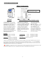
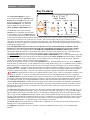
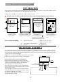
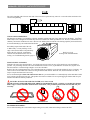
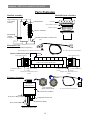
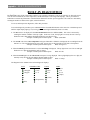
Swimming Pool and Spa Purification System
Pool Pilot™
Soft Touch
by Aqua Cal AutoPilot Inc.
Owners Manual
Installation and Operation
(For Indoor or Outdoor use)
IMPORTANT
Read This Manual Before Installing & Operating
Section 1a – GENERAL PRODUCT INFORMATION
Pool Pilot™
Soft Touch
by
Aqua Cal AutoPilot Inc.
.
Record The Following Information
Installer: ___________________________ Date of Installation: __________________________
Control Unit
Model Number:
ST-220
Cell
Model Number:
SC-
Control Unit
Serial Number: # ____________________________
_
Cell
Serial Number: # ____________________________
Factory Direct Customer Assistance…
HOTLINE: 1.800.786-7751 or 1.727.823.5642
FAX: 1.727.824.0847
e-mail to: [email protected]
Visit Us On The Internet @
http://www.autopilot.com
Manufactured by
Aqua Cal AutoPilot Inc.
2737 24th Street North • St. Petersburg • Florida 33713, U.S.A.
Pool Pilot™
Soft Touch
by Aqua Cal AutoPilot Inc.
1
Section 1b – GENERAL PRODUCT INFORMATION
IMPORTANT SAFETY INSTRUCTIONS
READ AND FOLLOW ALL INSTRUCTIONS
INSTALLATION AND EQUIPMENT RELATED
Installation of all Pool Pilot™ Soft Touch models:
When installing and using your Pool Pilot™ Soft Touch Control Box, basic safety precautions must
always be followed, including the following:
1.
Follow all aspects of the local and National Electrical Code(s) when installing your Control Box.
2.
During installation, mount your Control Box to ensure the least amount of direct exposure to rain, garden sprinkler water,
direct sunlight or any corrosive environment.
3.
DANGER – Risk of electrical shock. Install Control Box at least 10’ (3 m) for 115VAC Units, from the inside wall of
the pool or spa using non-metallic plumbing. 5’ (1.5 m) minimum distance for 230VAC Units.
4.
All field-installed metal components such as rails, ladders, drains or similar hardware within 10’ (3 m) of the spa or hot tub
shall be bonded to the equipment grounding bus with copper conductors not smaller than No. 8 AWG (8.4 mm²).
5.
6.
WARNING – Maintain water chemistry in accordance with manufacturer’s instructions.
DANGER – To reduce the risk of injury, do not permit children to use this product unless they are closely supervised
at all times. Children should not use spas, hot tubs or pools without permanent adult supervision.
Equipment Related
115/230VAC, 50/60 Hz Models (fixed wiring)
1
A wire connector is provided on your Pool Pilot™ Soft Touch to connect a minimum No. 8 AWG (8.4 mm²) solid copper
bonding conductor between this unit and any metal equipment, metal enclosures of electrical equipment, metal water pipe
or conduit within 5’ (1.5 m) of the unit.
2
A bonding terminal is located inside your Pool Pilot™ Soft Touch. To reduce the risk of electrical shock, this terminal
must be connected to the grounding means provided in the electrical supply panel with a continuous copper wire
equivalent size to the circuit conductors supplying your Pool Pilot™ Soft Touch.
3
A disconnection device from the power source, with a contact separation of at least 0.12” (3mm) in all poles, must be
incorporated in the fixed wiring for permanently wired units.
4
The input voltage to the Pool Pilot™ Soft Touch must match the 115/230VAC, 50/60 Hz jumper terminals on the Circuit
board, marked “TRANSFORMER PRIMARY”, shown on Page 5.
SAVE THESE INSTRUCTIONS
2
Section 1c – GENERAL PRODUCT INFORMATION
Table of Contents
Pool Pilot™
Soft Touch
by Aqua
Cal AutoPilot Inc
Section 1 GENERAL INFORMATION
1a
1b
1c
Product Information and Contact Numbers ............................................................................. 1
Important Safety Instructions................................................................................................... 2
Table of Contents..................................................................................................................... 3
Section 2 INSTALLATION
2a
2b
2c
Main Components.................................................................................................................... 4
Specifications
Control Box Connections......................................................................................................... 5
Electrical Connections
Cell Cord and Tri-Sensor Connections
ORP Connections
Cell and Manifold Installation ................................................................................................. 6
Verification of Flow Switch Protection ................................................................................... 6
Section 3 OPERATION
3a
3b
3c
Key Features – Control Panel .................................................................................................. 7
Pool Water Preparation ............................................................................................................ 8
Salt Requirement Chart
Start-Up Procedures ................................................................................................................. 8
Monitoring and Maintenance ................................................................................................... 9
Water Chemistry Parameters
Saturation Index
Section 4 SERVICE and MAINTENANCE
4a
4b
4c
Servicing .................................................................................................................................. 10
Control Box
Tri-Sensor
Servicing .................................................................................................................................. 11
Cell Removal
Cell Maintenance and Cleaning
Filter Backwashing .................................................................................................................. 11
Parts Explosion ........................................................................................................................ 12
Section 5 TROUBLESHOOTING
5a
Troubleshooting ....................................................................................................................... 13
Appendix Diagnostics............................................................................................................................... 14
3
Section 2a – INSTALLATION
Main Components
Tri-Sensor Assembly
Cell Power
FLOW
BOOST
SALT
CHECK
SYSTEM
Maximum Operating Pressure: 50 psi
Maximum Flow Rate: 100 gpm
Reversing
SuperCell
Flow In
Soft Touch
Control Box
CONTROL BOX converts incoming
AC power to a Low Voltage DC current,
which energizes the Cell(s). Set the
Control Box on a vertical surface away
from excessive exposure to heat and
moisture. Use the template to mark and
drill the (4) mounting holes and insert
the screws, leaving a ¼” gap. Hang the
control box on the screws and level.
Remove the cover by following the steps
on page 10 to access the mounting
holes to tighten the screws.
RATINGS:
Input Power: 115 VAC (3.0 AC amps)
230 VAC (1.5 AC amps)
50/60 Hz
Flow Out
Patented Automatic Flow Bypass Manifold Assembly
ELECTROLYTIC SUPERCELL
receives Low Voltage DC current from
the Power Circuit Board, which initiates
the electrolytic process. This process
converts ordinary table salt (Sodium
Chloride) to 100% Pure Sodium
Hypochlorite (Chlorine Bleach) or
Bromine (with the addition of Sodium
Bromide), which in turn purifies your
pool or spa.
See page 8 for salt requirements.
Cl2 Output Rating:
@ Cell Power 3
(8 amps DC)
SC-60
SC-48
SC-36
TRI-SENSOR ASSEMBLY
ensures that adequate
flow, 15gpm (3.4 m³/hr) minimum;
salt, 2500 – 3500 ppm
(2,5 – 3,5 gm/l) ideal range; and
water temperatures, above
55°F (13 °C) are satisfactory to
prevent abusive conditions for the
cell to operate. See page 10 for
instructions to remove and inspect
the tri-sensor assembly.
2.00 lbs/day (0.91 kg/day)
1.56 lbs/day (0.71 kg/day)
1.28 lbs/day (0.58 kg/day)
Output Power: Cell Power 1 (5.0* DC amps)
Agency Approvals: NSF, ETL us, ETL c, CE
Cell Power 2 (6.5* DC amps)
Cell Power 3 (8.0* DC amps)
*Indicates nominal amperage output. The dual axis controller will slightly vary the amps to optimize the power to the cell.
The cell and tri-sensor are located in a Patented Automatic Flow Bypass Manifold Assembly. 12’ (3.6 m) of Cell and TriSensor cords are provided with the unit. Ensure that the manifold is located within that distance from the control box with
enough slack to allow for removal for service or maintenance.
CAUTION: It is suggested to locate the cell downstream of all other equipment and on the pool return line only to avoid
over-saturation conditions of your spa. For applications other than as recommended, contact the factory.
4
Section 2b – INSTALLATION
Control Box Connections
Electrical Connections
Autopilot recommends that a licensed electrician or certified electrical contractor perform the electrical connections.
DANGER: ensure that the electrical panel or filter pump circuit breaker is turned OFF before wiring this unit.
Your Pool Pilot™ Soft Touch Control Box comes pre-wired from the factory for 230VAC (1.5 amps max draw) and can also
operate on 115 VAC, (3.0 amps max draw) at 50/60Hz. Short test lead wire are attached to the terminal strip and must be
removed prior to installation.
Converting to 115VAC is accomplished by accessing the circuit board, rewiring, and attaching the included jumper as shown
below. Remove the cover (see page 10) to access and ensure that the Jumper Connections on the circuit board marked
“TRANSFORMER PRIMARY” are matched to the LINE IN voltage. Follow all state/local codes for electrical installations.
►An additional jumper is
provided with your
Installation Kit for 115VAC.
Power Circuit Board
230VAC
Transformer
Location of the
Input Jumper Connections
TAB 9
TAB 10
TAB 7
TAB 8
TAB 5
TAB 6
TAB 3
TAB 4
TRANSFORMER PRIMARY
230 VAC
FACTORY SETTING
INNER CONTROL PANEL
TAB 9
115VAC
115VAC
TAB 10
TAB 7
TAB 8
TAB 5
TAB 6
TAB 3
TAB 4
TRANSFORMER PRIMARY
115 VAC
WIRING DIAGRAM
Top terminals factory wired – do not disturb.
Vac to PCB
Bonding
Lug
6-pin Tri-sensor
connector
Plug
#1 #2 #3 #4 #5 #6
Ground
Lugs
Conduit
connector
provided
AC
Line In
(Gr/Yel) (Br) (Bl)
Plug
2-pin ORP
Connector
CONTROL BOX BASE PLATE
Pool Pilot AC Line IN
Cell Cord
Connectors
AC LINE IN (Wiring diagram also located on inside of cover):
For 230 VAC; Brown (Br) = Line 1, Blue (Bl) = Line 2, Green w/Yellow Tracer (Gr/Yel) = Earth Ground
For 115 VAC; Brown (Br) = Line, Blue (Bl) = Neutral, Green w/Yellow tracer (Gr/Yel) = Earth Ground
Connect AC wires to Terminals #1, #2, and ground lug of the Pool Pilot from the LOAD SIDE of the time clock or the same
location as the circulation pump wires (pump connected to circuit breaker, time clock or electronic controller)..
Cell Cord. Each Cell Cord contains (2) Banana Plugs that attach to the (2) Banana Jacks on the bottom of the Control Box.
Polarity does not matter. The other end of the cell cord has a three-position plug that connects to the cell in any direction. For
the SC-36 and SC-48 Cell Types, ensure the red cap is inserted into the hole not used. See page 11 for service instructions.
Tri-Sensor Cord. The Tri-Sensor Cord connects to the keyed 6-pin harness on the Control Box Base Plate. The opposite
end of the cord connects to the Tri-Sensor Assembly with a locking ring quick connect. Align the grove and keyway on the
connector and twist the locking ring to ensure a proper connection. Refer to the instructions on pages 10 & 12 for diagrams
and additional instructions.
ORP Connection. When an ORP Chemical Controller is interfaced to your Pool Pilot™ Soft Touch, the Chemical
Controller will remotely control the purifier Output. Adjust the output level to 0% (All Purifier Output lights off) and connect
the ORP controller to the 2-pin connector on the Control Box Base Plate. When the ORP is activated, the system will generate
chlorine. If it is desired to have a visual confirmation of chlorine generation with the ORP feed is on, increase the Purifier
Output to show the first LED light by pressing the arrow up one time. When the ORP feed is on, this light will flash.
WARNING: THE ORP CONNECTIONS ARE DRY CONTACT INPUTS, DO NOT ENERGIZE THESE
INPUTS! DAMAGE TO THE CONTROL BOX WILL OCCUR AND WILL VOID THE WARRANTY.
5
Section 2c – INSTALLATION
Cell and Manifold Installation
Your Pool Pilot System is adaptable for use with either the SC-36, SC-48 or SC-60 cell. All models come pre-assembled with
a Patented Automatic Flow Bypass Manifold Assembly. The manifold must be located as the last accessory in the POOL
RETURN LINE only. For pool/spa combinations or special plumbing configurations, please contact the factory for assistance
in locating the manifold.
Standard Manifold Assembly (all models):
WARNING: Do not mount the manifold upside down.
Maximum flow rate 100 gpm (22.6 m³/hr). We recommend using a 2 lb spring bypass check valve for flow rates greater than
100 gpm (22.6 m³/hr) and plumbing it parallel to the manifold. For Pool-Spa combinations, the manifold assembly must be
mounted in the Pool return line, so as to avoid over saturation of the spa when isolated.
To Pool Return
*One set of 68mm x 2” metric adapters (#19059) included with European Systems.
For other plumbing configurations, please contact the factory for assistance.
Verification of Flow Switch Protection:
It is important to annually inspect and verify the safe and proper operation of the Tri-sensor’s Flow Switch protection device.
Autopilot recommends following this procedure to verify that the flow switch is working as designed, which is to halt power
from being sent to the cell in the presence of insufficient flow. A defective Flow Switch can cause serious equipment damage.
Using a small plastic wrap (saran wrap, food wrap or zip lock bag), block off flow to the upper portion of the manifold by
wrapping the strainer screen with the plastic wrap and placing it back in the union and tightening. Operating the system on
with this blockage should detect a FLOW obstruction, turning the FLOW-OK light off and activating a single red SERVICE
flashing light. Once this protection feature has been verified, remove the plastic wrap, replace the strainer screen and resume
operation. Turn the output dial to OFF and contact the factory if the flow switch protection does not activate properly.
Plastic Wrap
CLEAN UNION
SCREEN
REGULARLY
6
Section 3a – OPERATION
Key Features
Pool Pilot™
Soft Touch
The Control Panel Display provides a
series of control buttons for OUTPUT level,
BOOST mode and SETUP functions, with
diagnostic indicator lights for FLOW-OK,
SALT and SERVICE. Two additional
indicator lights show the selected setup
CELL POWER and REVERSING cycle.
OUTPUT
100%
SERVICE CELL POWER
1
2
SALT
3
OK
REVERSING
SHORT
LOW
NORMAL
LONG
ADD Concealed Set Up Button
FLOW-OK
50%
BOOST
The Pool Pilot™ Soft Touch Purifying
OUTPUT level is adjustable from 0% (OFF)
to 100 %(MAX). Press the Up/Down Arrows
0%
to set the desired output level. When increasing
or decreasing the Output with the Up/Down buttons, the three lights of the Cell Power and Reversing will light or not light at
all, and will remain that way for a period of a few seconds. The Cell Power lights will stage up (increasing) or down
(decreasing) to indicate the increments of output of each Output light. Little adjustment is needed once the initial setting is
established. The selected output level will remain steady when the system is at rest and will begin flashing when the system is
producing the purifying agent.
Note: The Pool Pilot™ Soft Touch does not test for purifier levels nor automatically adjust to maintain a desired
purifier level. This is done by periodically testing the water and adjusting the output levels up or down, as needed.
The Pool Pilot Soft Touch is designed with an AUTOMATIC TEMPERATURE COMPENSATION feature, which
automatically adjusts the output level setting based upon changes in seasonal water temperatures only. This unique feature
conveniently compensates for warm (more purifier needed) or cold (less purifier needed) water conditions.
The SETUP Mode allows the user to program the CELL POWER and REVERSING cycle. To enter Setup Mode, press and
hold the concealed Setup button (which can be felt under the label) until the CELL POWER light begins flashing. The Pool
Pilot™ Soft Touch is set on “2“ from the factory. Use the Up/Down Arrows to change the Cell Power setting. Adjust the
OUTPUT level to the new setting to maintain proper sanitizer levels.
Pressing the Setup Button once more will go to the REVERSING cycle. The Pool Pilot™ Soft Touch is set on “NORMAL”
from the factory for ideal cell life. Use the Up/Down Arrows to change the Reversing cycle. For conditions such as extremely
high calcium levels or conditions that can cause the cell to scale quicker than the self-cleaning cycle can control, change the
setting to “SHORT”. For optimum water chemistry balance according to the Saturation Index, see page 9, you can change the
REVERSING cycle to “LONG”. Pressing the setup button once more will leave the Setup Mode and save the programmed
Cell Power and Reversing settings. Test your water chemistry parameters monthly and compare to the Saturation Index.
WARNING: Changing the Reversing cycle to SHORT will also reduce cell life. However, operating the cell under scaled
conditions on “Normal” or “Long” is more detrimental to the life of the cell, and changing the Reverse cycle is suggested.
The BOOST Button overrides the normal Purifier Output % and activates at 100%, indicated by a solid Boost Light, when it is
pressed once, and will produce the purifying agent for 24 hours. The purifying agent can be produced for 72-hours, indicated
by a flashing Boost Light, by pressing and holding the BOOST button for 8-seconds from the Boost-Off position. This is
called the Super-Boost Mode. In either mode, the purifying agent is produced continuously, throughout the normal On/Off
cycles of the pump and throughout all power line disturbances. The system will discontinue operation of the Boost or Super
Boost mode after the 24-hr or 72-hr cycle has passed, of if the boost button is pressed once more, then return to the normal
purifying output setting.
The SALT light indicates the salt level in the water. The salt level should be maintained between 2500 – 3500 ppm (2,5 – 3,5
g/l), where the SALT-OK light will display. If the salt level drops between 2400 - 2000 ppm (2,4 -2,0 g/l), the SALT-LOW
light will display and the system will reduce efficiency in producing the purifying agent. If the salt level drops below 1900
ppm (1,9 g/l), the SALT-ADD light will display and the system will halt production of the purifying agent. The Pool Pilot™
Soft Touch can also handle special application salt levels of up to 35,000 ppm (35,0 g/l) without any adverse effects to the unit.
(NOTE: HIGH Salt level does not affect purifier production but can cause corrosion problems with metallic fixtures, light
rings, ladders and hand rails.) See Appendix (page 14) to determine your salt level.
The FLOW-OK light turns on when there is sufficient flow. Insufficient flow is indicated by the Flow-OK light off and a
Flashing Service Light (single flash pattern).
The SERVICE light flashes when service is needed. Check the Troubleshooting Section, page 13, for troubleshooting
solutions.
7
Section 3b – OPERATION
Pool Water Preparation
Salt Requirements
It is important that with typical pools, a salt residual of 2500 to 3500 ppm (2,5 – 3,5 g/l) be maintained at all times for peak
efficiency. The Pool Pilot™ Soft Touch can also handle special application salt levels of up to 35,000 ppm (35,0 g/l) without
any adverse effects to the unit.
NOTE: HIGH Salt level does not affect purifier production but can cause corrosion problems with metallic fixtures, light
rings, ladders and handrails.
The amount of salt required depends on the size of the pool and the present salt level. As the salt is being added, we
recommend running the circulation pump continually for 24 hours with the main drain opened. Brushing the salt towards the
bottom main drain will assist in the dissolve rate and prevent possible staining with certain types of salt.
We recommend the use of AutoSoft Plus™ Water Conditioning Salt. AutoSoft Plus™ salt contains 99.8% pure Sodium
Chloride (NaCl) without Iodine or the Anti-Caking additive, Yellow Prussiate of Soda (YPS). Iodine and YPS can cause a
localized tint to the water or yellow staining on the cementitious finish if allowed to rest undissolved on the finish for extended
periods of time. AutoSoft Plus™ is blended with the proper amount of stabilizer to maintain a proper level within the
recommended range when added according to the salt chart on the box.
Granular Salt, Table Salt, Solar Salt or Water Conditioner Pellets can also be used but will have different dissolve rates. If the
salt you use contains Iodine or YPS, constant brushing will help the dissolve rate and prevent staining due to the additives in
the salt. Ensure that the salt you use contain a minimum purity of 99% Sodium Chloride (NaCl).
NOTE: Do not use Rock Salt due to its high levels of impurities.
TEST YOUR WATER FOR SALT LEVEL FIRST with the provided salt test strips,
and then use the chart below to determine the amount of salt to add.
SALT REQUIREMENT CHART
SALT Level
Before Addition
POUNDS (kg) OF SALT NEEDED FOR 3000 PPM RESIDUAL
Pool Volume in Gallons (m³)
0 ppm
1,000
(3.77)
25 (11.3)
2,500
(9.43)
63 (28)
5,000
(18.9)
126 (57)
7,000
(28.3)
175 (79)
10,000
(37.7)
252 (113)
15,000
(56.6)
378 (170)
20,000
(75.4)
504 (227)
30,000
(123.2)
756 (340)
500 ppm
21 (9.5)
53 (24)
106 (48)
147 (66)
212 (95)
318 (175)
424 (191)
636 (286)
750 ppm
19 (8.6)
48 (22)
96 (43)
133 (60)
192 (86)
288 (130)
384 (173)
576(259)
1000 ppm
17 (7.7)
43 (19)
86 (39)
119 (54)
172 (77)
258 (116)
344 (155)
516 (232)
1500 ppm
13 (5.9)
33 (15)
66 (30)
91 (41)
132 (59)
198 (89)
264 (119)
396 (178)
2000 ppm
8 (3.6)
21(9.5)
42 (19)
56 (25)
84 (38)
126 (57)
168 (76)
252 (113)
2250 ppm
6 (2.7)
15 (7)
30 (14)
42 (19)
60 (28)
90 (41)
120 (54)
180 (81)
Note: The above chart is based on 1 lb. (2.2 kg) of salt added to 1,000 gallons (3.8 m³) to increase your salt residual 120-ppm.
Start Up Procedures
Keep the Output Setting on your Pool Pilot™ Soft Touch on 0% (OFF) until you get your water clear, blue and properly
balanced.
1.
After balancing your water chemistry according to the Water Chemistry Parameters shown on page 9, add the proper
amount of salt (see Salt Requirement Chart above) and circulate 24-hours prior to starting your Pool Pilot™ Soft Touch.
2.
The following day, turn your Output Level to 50% and operate normally. For the first two weeks, test the water every 2-3
days for proper Purifier levels. Raise or Lower the Output Control Setting as needed, according to your test results.
3.
Once your Output Level has been established, you will only need to adjust your chlorine level according to increased
bather usage by increasing the Purifier Output % or by using the Boost button.
8
Section 3c – OPERATION
Monitoring and Maintenance
Water Chemistry Parameters - VERY IMPORTANT NOTE! Your Pool Pilot™ Soft Touch is designed to provide
Purifier on a daily basis. We recommend the following water chemistry ranges and periodic checks to monitor your systems
efficiency. Always follow all local and state requirements.
Biweekly Checks:
Free Chlorine: 1.0 – 3.0 PPM
Or Bromine: 2.0 – 4.0 PPM
pH:
7.2 – 7.8
Monthly Checks:
Calcium Hardness: 200 – 400 PPM
Salt Residual:
2500 – 3500 PPM
Total Alkalinity:
80 – 120 PPM
Saturation Index:
± 0.3 pH of saturation
Cyanuric Acid:
60 – 80 PPM
Visual Cell Inspection for wear, scale or debris
CHLORINE/BROMINE REQUIREMENTS: During Peak Purifier Demand (rainy season or heavy bather usage) it may be
necessary to increase your purifier level by increasing your Output Level setting and/or pump run time. Conversely, during
Low Purifier Demand, you can decrease your Output Level to a lower setting. For extremely Heavy Purifier Demand or to
boost your purifier levels quickly, you can Boost the system or supplement with a Potassium Monopersulfate based shock. If
the water is clear but is difficult getting a bromine residual using DPD or test strips, we recommend using an OTO test kit.
NOTE: During cold-water conditions, below 60ºF, Purifier demand is reduced significantly. For colder climate regions
with sustained low or freezing temperatures, contact your local pool professional for proper pool winterizing instructions.
WARNING: Excessive chlorine levels can cause corrosion damage to stainless steel rails, ladders, heater heat exchangers,
light faceplates and other metallic equipment. Avoid over saturation of chlorine levels.
pH: When pH levels fall below the recommended range, Purifier is used up quickly and can be damaging to equipment. For
pH levels higher than the recommended range, Purifier becomes less effective and works harder to keep your pool purified.
Improper pH also contributes to the strong smell, red eyes, dry itchy skin and brittle hair conditions associated with “too much
Chlorine”.
CALCIUM HARDNESS AND TOTAL ALKALINITY: Your Pool Pilot™ Soft Touch provides 100% pure sodium
hypochlorite and does not affect the calcium hardness or total alkalinity levels. Maintain and balance only as needed.
CYANURIC ACID (STABILIZER/CONDITIONER): This chemical goes by either trade name and allows the chlorine
residual to last longer by protecting it from the UV degradation of the sun. With low or no Cyanuric acid it is possible for the
chlorine to be used up as quickly as it enters the pool. Check and maintain your cyanuric acid levels at the same time as your
salt level, as these tend to deplete at the same rate.
NOTE: For Bromine or indoor pools, it is not necessary to add stabilizer.
SALT RESIDUAL: Your Pool Pilot™ Soft Touch works most efficiently with salt levels between 2500- 3500 ppm (2,5 – 3,5
g/l). If it falls below 2500 ppm (2,5 g/l), determine the salt level and adjust according to the SALT REQUIREMENT. Low
salt will cause premature deterioration of the Cell blades. For “SEAWATER” pools, your Pool Pilot™ Soft Touch is designed
to handle up to 35,000 ppm (35,0 g/l), however, salt levels above 6000 ppm (6,0 g/l) can be corrosive to metallic fixtures.
BROMINE RESIDUAL: Along with the normal Salt level, add 1lb (0.45 kg) Sodium Bromide (NaBr) per 2000 gallons (0.75
m³) of water. Your Pool Pilot™ Soft Touch will now generate Bromine to purify your pool. Maintain your bromine level by
checking your salt level. Once your salt falls below the recommended range, we suggest you add 1lb (0.45 kg) sodium
bromide with every 50 lbs (22.5 kg) of salt added. We recommend testing Bromine Purifier levels with an OTO test kit.
SATURATION INDEX (SI): a formula used to ensure that your total water chemistry does not fall into a scale forming or
corrosive condition. Either condition can cause premature damage to the Cell, equipment and cementitious finish. Have your
water professionally tested periodically according to the Saturation Index or use this chart to determine your water balance.
SI = pH + TF + CF + AF – Constant
Temperature
TF Calcium Hardness CF
Total Alkalinity AF
TDS
Constant
60F 15.6C
0.4
150
1.8
75
1.9
0 – 1000
12.1
66F 18.9C
0.5
200
1.9
100
2.0
1001 +
12.2
76F 24.4C
0.6
250
2.0
125
2.1
84F 28.9C
0.7
300
2.1
150
2.2
94F 34.4C
0.8
400
2.2
200
2.3
103F 39.4C
0.9
600
2.4
250
2.4
Test your water for pH, Calcium Hardness, Total Alkalinity and TDS levels. Use the equivalent Factor in the SI equation.
SI = +0.3; balanced
SI above + 0.3; scaling, staining or cloudy water conditions.
SI below -0.3; corrosive to metals, etches/deteriorates plaster finishes or skin irritating conditions.
9
Section 4a –SERVICE and MAINTENANCE
CONTROL BOX
There are little serviceable parts on the Pool Pilot™ Soft Touch Control Box except the fuses. For any other problems with the
Control Box, please contact the Factory or Authorized Dealer/Service Center.
To remove the Control Box Cover and access the fuses, follow these steps.
DANGER: TURN OFF THE POWER FROM THE CIRCUIT BREAKER BEFORE SERVICING THIS UNIT.
1
2
POOL PILOT™
Soft Touch
f
3
Control Circuit Board
F3
Front of Unit
Top Cover
F2
Inner Metal
Cover
Wire Harness Connection
Inside Top Cover
F1
Loosen (4) knobs
(you do not need to)
(remove these).
Lift off cover and disconnect
wire harness (Control Circuit
board removes with cover).
Fuse Location and Ratings
Remove (3) screws and
lift off metal cover.
The (4) Mounting holes, at
each corner are accessed here
(without removing metal cover).
F1
Main AC Power Fuse
F2
F3
Control Panel Circuit Board Fuse
Cell Fuse
Access is gained to
electrical connections,
fuses, and pump/aux
relay.
3 Amps 250 VAC (230 Volts)
6 Amps 250 VAC (115 Volts)
3 Amps 250 VAC
20 Amps 250 VAC
TRI-SENSOR ASSEMBLY
The Tri-sensor assembly tests for Flow, Salt and Water temperatures. A minimum flow rate of 15 gpm (3.4 m³/hr) is required
to activate the flow switch. As the water flow closes the paddle, a magnet activates a micro switch to verify proper flow. The
Salt sensor protects against low salt levels and the temperature sensor protects against cold water temperatures. Both of which
can contribute to accelerated cell failure.
►Note: The use of high strength magnet devices in the close proximity
of the tri-sensor can cause the flow switch to read incorrectly.
Remove the Tri-Sensor as follows (with pump off):
directional
arrow
Remove both screws from the sides of the Tee Assembly.
With the aid of large Channel-lok® (or similar) pliers, firmly
grip the Tri-Sensor assembly and move back and forth
while removing the Tri-Sensor from the tee.
Inspect the thin metalic paddle for erosion and straightness.
Take care not to twist or tweak this paddle, which can cause
inaccurate flow readings.
Inspect the salt sensor blades for scale and debris and clean
if necessary. See page 13 for cleaning instructions. Follow
the directions for Manual Cell Cleaning.
Check the tri-sensor assembly for any damage to the plastic
housing and replace if needed.
screws
one on each side
10
Section 4b –SERVICE and MAINTENANCE
Cell
The Cell is installed with Unions on each end of the cell to allow quick and easy removal. Loosen the unions and remove the
cell from the plumbing.
Side View of Cell and Unions
VISUAL CELL INSPECTION:
The titanium Cell blades, seen inside the Cell body, should be straight and clear of any debris between the blades. Your Pool
Pilot™ Soft Touch is designed to automatically self-clean calcium scale build-up within the Cell. However, imbalanced water
chemistry and certain conditions can cause a heavier scale build up that exceeds the self-cleaning capability and would need to
be cleaned manually by the method described below.
Periodically inspect both ends of the cell.
A White Flaky or Crusty build-up on the
edge or between the blades will prematurely
deplete the life of the cell. Immediately
clean the cell and determine the cause of
scaling. See Troubleshooting Section, page 13.
End View of cell
Looking at the Titanium Blades
MANUAL CELL CLEANING:
With the Cell removed as described above, use a high-pressure hose nozzle to spray off as much loose scale and debris as
possible. Any remaining calcium scale can be treated with a mixture of one (1) part Muriatic Acid into four (4) parts water.
Mix the solution in a container high enough to cover the Cell blades.
Remove the Cell cord and immerse the Cell so that the blades are completely covered in the solution for up to 15 minutes. An
effervescences action indicates the calcium is being neutralized and cleaned. Drain the cell, flush with fresh water and reinspect. Repeat the immersion if necessary.
We recommend using Lo-Chlor Salt Cell Protector Plus as a prevention additive to continually help soften and reduce buildup of calcium scale deposits in the cell. This product also reduces calcium scale on exposed aggregate finishes and new pool
finishes and enhances chlorine production.
DANGER: ALWAYS ADD ACID TO WATER, never water to acid.
NEVER USE ANY SHARP OR METALLIC OBJECTS TO REMOVE SCALE. Scraping or scratching the titanium
blade’s edge or surface will allow chemical attack of the blade, cause premature failure of the Cell and will void your
warranty.
Hacksaw Blades
Screwdrivers
Forks
Knives
FILTER BACKWASHING:
We recommend turning the Control Panel Output setting to 0% (OFF) when backwashing a Sand or DE filter.
11
Section 4c –SERVICE and MAINTENANCE
Parts Explosion
Manifold Assembly:
Manifold Union w/Strainer:
(#19065)
Upper manifold
w/Tri-sensor
(#941R)
TRI-SENSOR
Union Nut
Union O-Ring (#19014)
Strainer (#19064)
CELL w/ UNIONS
MANIFOLD
UNION
w/Strainer
MANIFOLD BASE w/Check Valve
(#941)
Electrolytic Cell:
(Cell Unions and Cord ordered separately)
Red Cap Plug for SC-36 and SC-48 cell cord (#19050)
12’ (3.6m) Cell Cord (# 952-ST/DIG)
UNION COMPLETE (#19070)
Union O-Ring (#19013)
Union O-Ring (#19013)
Cell (#’s SC-36, SC-48, SC-60)
1.5” Half union (#312-C)
2” Slip Union (#312-B)
(38 mm)
(51 mm)
Nut only for 2” Slip Union (#312-A)
(51 mm)
2” Slip Union (#312-B)
1.5” Half Union (#312-C)
(51 mm)
(38 mm)
Nut Only for 2” Slip Union (#312-A)
(51 mm)
Tri-Sensor Assembly:
(Cord Ordered Separately)
Tri-Sensor
(#909-GO1.5)
View of locking
Quick connect heads
Directional Flow Indicator
Tri-Sensor O-Ring (#19028)
Flow Switch Paddle
Temperature Sensor Post
Salt Sensor Blades
Direction of Water Flow
12
12’ (3.6m) Tri-Sensor Cord (# 956-1)
Section 5a – TROUBLESHOOTING
TROUBLESHOOTING
PROBLEM
1)
2)
3)
4)
5)
6)
7)
8)
9)
10)
11)
12)
13)
CAUSE
SOLUTION
Insufficient Purifier Production.
A) The test kit reagents or test strips are old or expired.
B) The unit is set too low in relation to purifier demand.
C) The circulation run time is insufficient.
D) The bather load has increased.
A)
B)
C)
D)
E) The body of water being purified leaks.
F) Low Salt.
G) “Cell Power” selection not matched to the cell installed.
H) Purifier loss due to intense sunlight
Scale Build-up within the Cell.
A) The water being purified contains high pH, total
alkalinity and calcium hardness levels.
(Cell scales within 2 – 3 weeks)
B) Power Supply not reversing polarity.
(Cell constantly scales within 3 – 5 days)
DC Plug and Cell Terminals Burned.
A) The Cell terminals are wet due to a leaking cell body.
B) The Cell plug is not securely pushed onto the cell
terminals, allowing moisture to seep into the plug.
Premature Cell Failure (Requires Replacement Cell).
A) Abnormally high Cell usage due to an insufficient
Stabilizer (Cyanuric acid) level.
B) Excessive Scale/Debris in the Cell.
C) “Cell Power” selection not matched to the Cell installed.
White Flakes in the Water.
A) This occurs when excessive calcium hardness is
present. Usually due to water chemistry imbalance.
No Power to the Control Box.
A) Internal Fuse blown.
B) Circuit Breaker tripped.
E)
F)
G)
H)
Retest with new Reagents or Strips.
Turn up the output setting.
Increase your pump run time.
Same solution as (B) or add a Non-Chlorine Shock
containing Potassium Monopersulfate to supplement.
Repair the leak and rebalance as needed.
Check the residual salt level and adjust as needed.
Follow the SET UP procedures to match the cell, see page 7.
Check your stabilizer level and adjust if needed.
A) Calculate Saturation Index to assure balanced water.
Adjust chemicals and clean the Cell. See pages 9 & 11.
B) Contact the factory for Warranty Status/Procedures.
A) Contact the factory for Warranty Status/Procedures.
B) Ensure the Cell cord plug is pressed completely onto the
Cell terminal. Check the terminals and clean with a dry
cloth to remove all dirt and corrosion.
A) Check the stabilizer level and adjust to recommended levels.
B) See Section 2 above.
C) Follow the SETUP procedures to match the cell, see page 7.
A) Visually inspect Cell for scale build-up and clean the cell as
described on page 11. Adjust your water chemistry.
A) Check and replace fuse. See page 10.
B) Check the power going to the Control Box. Reset the
Circuit Breaker.
SERVICE Light (Single RED Flash and Flow-OK light off).
A) Contact the factory for Warranty Status/Procedures.
A) Tri-Sensor Defective.
B) Insufficient Flow (Min. 15 gpm) (3.4 m³/hr)
B) Ensure your Filter and Cell are clean of debris.
Check all valves that might divert flow away from the cell.
SERVICE Light (Double RED Flash)(Purifier is producing).
A) High Cell Volts with Low Amps
A) Check cell for calcium build-up or scale deposits.
Cell is depleted and needs replacement.
Cell cord is loose or defective. Ensure that the cord is firmly
attached to the cell. Check the Banana Plug connections.
SERVICE Light (Triple RED Flash)(Purifier production halted).
(Microprocessor version V1.4 or older)
A) High Cell volts with Extremely Low Amps.
A) Heavily scaled cell or failed cell.
(Microprocessor version V1.5 or newer)
A) Improperly wired or failed Power Supply.
A) Ensure voltage input matches wiring connection (page 5).
SERVICE Light (Quadruple RED Flash)(Purifier is producing).
A) Tri-sensor or tri-sensor cord is loose or defective.
A) Inspect and tighten or replace.
LOW SALT Light activated (Purifier is producing) .
A) Salt level Low (below 2400 ppm (2,4 g/l)).
A) Check with Salt test strips or meter and adjust as needed.
ADD SALT Light activated (Purifier production halted).
A) Salt level extremely low (below 2000 ppm (2,0 g/l)).
A) Check with Salt test strips or meter and adjust as needed.
Unable to set output to a high level.
A) Temperature is too low (below 55F (13C)).
A) The Pool Pilot has limited output to protect the cell.
13
Appendix – BUILT-IN DIAGNOSTICS
BUILT-IN DIAGNOSTICS
The Pool Pilot™ Soft Touch Control Box contains a way to display a diagnostic report on its operation. It allows the user to
view the salt concentration, the water temperature, and the Electrolytic Cell voltage and amperage. This is provided for a
technician to evaluate the performance of the Pool Pilot without the need for special equipment. The values are measured by
counting the number of flashes of the lights, as described below.
To access and interpret the diagnostics, follow this procedure:
To start the diagnostic procedure, press and hold both the UP and DOWN buttons at the same time. Hold them pressed
until the output display lights go out, leaving just the bottom light illuminated (about 5 seconds).
1. The first value to be displayed is the salt concentration in Parts Per Million (PPM). This value is measured by
counting the number of flashes of the top 3 lights. In the case of salt, the top light is not used, the next to the top
flashes the 1000’s digit and the third light flashes the 100’s digit in ppm.
Example: 2 flashes/pause/8 flashes/pause
Read: 2,800 PPM
2. The second value is the water temperature in degrees Fahrenheit. When this is displayed, the second light from the
bottom is on. The top light flashes the 100’s digit, the next the 10’s digit and the next the units of temperature.
Example: 8 flashes/pause/6 flashes/pause
Read: 86 Degrees F
3. When the third light from the bottom is on, the cell voltage is displayed. The top light is not used. The second light
flashes the 10’s digit and the third the units of voltage.
Example: 2 flashes/pause/8 flashes/pause
Read: 28 Volts
4. When the fourth light is on the cell current in amperes is being displayed. The top light displays the 10’s digit (not
normally used), the next the units and the third the tenths of amps.
Example: 5 flashes/pause/5 flashes/pause
Read: 5.5 Amps
The diagrams below summarize the built-in diagnostic displays.
SALT
TEMPERATURE
x100 °F
x1000 ppm
x10 °F
x100 ppm
x1 °F
VOLTS
x10 V
x1 V
(Volts)
(Temperature)
(Salt)
14
AMPS
x10 A
x1 A
x0.1 A
(Amps)