1
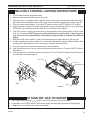
Unvented Gas Log Heater
or
Vented Decorative
Appliance
Models: NB18, NB24, NB18SC,
NB24SC, NB18SCR, NB24SCR
Installation and Operating
Instructions
WARNINGS
If the information in this manual is not followed
exactly, a fire or explosion may result causing
property damage, personal injury or loss of
life.
– Do not store or use gasoline or other
flammable vapors and liquids in the vicinity
of this or any other appliance.
– WHAT TO DO IF YOU SMELL GAS
• Do not try to light any appliance.
• Do not touch any electrical switch; do not
use any phone in your building.
• Immediately call your gas supplier from
a neighbor's phone. Follow the gas
supplier's instructions.
• If you cannot reach your gas supplier, call
the fire department.
– Installation and service must be performed
by a qualified installer, service agency or
the gas supplier.
810107
NB18/24 cover
This appliance may be installed in an
aftermarket, permanently located,
manufactured (mobile) home, where not
prohibited by local codes.
This appliance is only for use with the type
of gas indicated on the rating plate. This
appliance is not convertible for use with other
gases.
This is an unvented gas-fired heater. It uses
air (oxygen) from the room in which it is
installed. Provisions for adequate combustion
and ventilation air must be provided.
Refer to Page 4.
INSTALLER: Leave this manual with the appliance.
CONSUMER: Retain this manual for future reference.
81D0107 12/11 Rev. 9
NB18/NB24 Gas Log Set
CONTENTS
Thank you and congratulations on your purchase of a Monessen Log Set
Please read the Installation and Operation Instructions before using the appliance!
IMPORTANT: Read all instructions and warnings carefully before starting installation.
Failure to follow these instructions may result in a possible fire hazard and will void the warranty.
Important Safety Information.......................................3
Codes........................................................................3
Product Features and Specifications .........................5
Gas Pressures..........................................................5
Ignition Controls - Millivolt.........................................5
Pilot/ODS..................................................................5
Thermal Generator....................................................5
Fireplace and Hearth Dimensions ..............................6
Placement in a Fireplace w/ Restrictive Barrier.............6
Clearances and Height Requirements . ......................7
Floor Clearance ..........................................................10
Fireplace Preparation . ...............................................11
Vented Application Installation NB, NBSC Models .................................................12
Flame Appearance.......................................................23
Operating Instructions - Millivolt...............................23
For Your Safety Read Before Lighting....................24
Millivolt Control Lighting Instructions.......................25
To Turn Off Gas to Heater.......................................25
Match Lighting Instructions.....................................26
Check Gas Pressure & Electrical Installation - SCS27
Command Center Wall Installation..........................27
Wall Switch Installation...........................................27
Wiring Diagram - SCS.............................................28
Operating Instructions - Signature Command..........29
For Your Safety Read Before Lighting....................29
Operating Instructions.............................................30
To Turn Off Gas to Appliance..................................30
Signature Command System Operation Instructions31
Gas Line Connection .................................................13
Touch Screen Remote Control Operation................... 34
Check Gas Pressure ..................................................13
Millivolt....................................................................13
Cleaning & Servicing..................................................39
Electrical Wiring - Millivolt..........................................14
Optional Wall Switch or Thermostat........................14
Connect Remote Receiver......................................15
Check System Operation........................................15
Final Installation..........................................................16
Cast Iron Grate Installation.....................................16
Rock Wool Placement.............................................17
Berkley Oak Log Placement ..................................17
Ember and Rock Placement...................................19
Stoney Creek Log Placement.................................20
Troubleshooting..........................................................40
Millivolt Control System...........................................40
Signature Command System..................................42
Replacement Parts......................................................43
Burner Assembly - Millivolt......................................43
Burner Assembly - SCS..........................................44
Berkeley Oak Refractory Logs................................45
Stoney Creek Refractory Logs................................46
Massachusetts Residents Only.................................50
Warranty.......................................................................51
81D0107
IMPORTANT SAFETY INFORMATION
NB18/NB24 Gas Log Set
OWNER
INSTALLER
Please leave these instructions with the appliance.
Please retain these instructions for future reference.
IMPORTANT
WARNING
Read these instructions carefully before installing or trying to operate this vent-free gas heater.
• Any change to this heater or its controls can be dangerous.
• Improper installation or use of the heater can cause serious injury or death
from fire, burns, explosion or carbon monoxide poisoning.
• Do not allow fans to blow directly into the fireplace. Avoid any drafts that alter
burner flame patterns.
• Do not use a blower insert, heat exchanger insert or other accessory, not
approved for use with this heater where applicable.
1. Due to high temperatures, the appliance should be
located out of traffic and away from furniture and
draperies.
2. Children and adults should be alerted to the hazard
of high surface temperature and should stay away to
avoid burns or clothing ignition.
3. Young children should be carefully supervised when
they are in the same room with the appliance.
4. Do not place clothing or other flammable material on
or near the appliance.
5. Any safety screen or guard removed for servicing an
appliance, must be replaced prior to operating the
heater.
6. Installation and repair should be done by a qualified
service person.
7. To prevent malfunction and/or sooting, an unvented
gas heater should be cleaned before use and at least
annually by a professional service person. More frequent cleaning may be required due to excessive lint
from carpeting, bedding material, etc. It is imperative
that control compartments, burners and circulating air
passageways be kept clean.
8. CARBON MONOXIDE POISONING: Early signs of
carbon monoxide poisoning are similar to the flu with
headaches, dizziness and/or nausea. If you have these
signs, obtain fresh air immediately. Have the heater
serviced as it may not be operating properly.
9. The installation must conform with local codes or, in
the absence of local codes, with the National Fuel
Gas Code, ANSI Z223.l/NFPA54.
10. The NB(18,24) and NB(18,24)SC units comply with
ANSI Z21.11.2 Unvented Heaters, latest edition and
also complies with ANSI Z21.60 Decorative Vented
Appliances for Solid Fuel Burning Fireplaces, latest
edition. The NB(18,24)SCR units comply with ANSI
Z21.11.2 Unvented Heaters, latest edition ONLY.
81D0107
State and local codes may only allow operation of
this appliance in a vented configuration. Check your
state or local codes. For vented operation, see “Vented
Instructions” in this manual.
11. Do not install the heaters in a bathroom or bedroom.
12. Correct installation of the logs, proper location of the
heater, and annual cleaning are necessary to avoid
potential problems with sooting. Sooting, resulting
from improper installation or operation, can settle on
surfaces outside the fireplace. See log placement
instructions for proper installation.
13. Avoid any drafts that alter burner flame patterns. Do not
allow fans to blow directly into fireplace. Do not place
a blower inside burn area of firebox. Ceiling fans may
create drafts that alter burner flame patterns. Sooting
and improper burning will occur.
14. Caution: Candles, incense, oil lamps, etc. produce
combustion by-products including soot. Vent-free
appliances will not filter or clean soot produced by
these types of products. In addition, the smoke and/or
aromatics (scents) may be reburned in the vent-free
appliance which can produce odors. It is recommended
to minimize the use of candles, incense, etc. while the
vent-free appliance is in operation.
15. This is an unvented gas-fired heater. It uses air
(oxygen) from the room in which it is installed. Provisions for adequate combustion and ventilation air must
be provided.
16. This heater shall not be installed in a room or space
unless the required volume of indoor combustion air is
provided by the method described in the National Fuel
Gas Code, ANSI Z223.1/NFPA 54, the International
Fuel Gas Code or applicable local codes.
17. Keep room area clear and free from combustible
materials, gasoline and other flammable vapors and
liquids.
IMPORTANT SAFETY INFORMATION
NB18/NB24 Gas Log Set
WARNING
Massachussetts residents only:
Refer to Page 46 for
additional information.
Never connect unit to private (non-utility)
gas wells. This gas is commonly known
as wellhead gas.
NB18, NB18SC, NB24, NB24SC
Certified To
ANSI Z21.11.2 Latest Edition
Unvented Heaters &
Z21.60 Latest Edition;
CSA 2.26 Latest Edition
NB18SCR, NB24SCR
Certified To
ANSI Z21.11.2, Latest Edition
Unvented Heaters
CODES
Adhere to all local codes or, in their absence, the latest
edition of THE NATIONAL FUEL GAS CODE ANSI Z223.1
or NFPA54 which can be obtained from…
American National Standards Institute, Inc.
1430 Broadway
New York, NY 10018
or
National Fire Protection Association, Inc.
Batterymarch Park
Quincy, MA 02269
WARNING
18. Unvented gas heaters are a supplemental zone heater.
They are not intended to be the primary heating appliance.
19. Unvented gas heaters emit moisture into the living
area. In most homes of average construction, this
does not pose a problem. In houses of extremely
tight construction, additional mechanical ventilation is
recommended.
20. During manufacturing, fabricating and shipping, various
components of this appliance are treated with certain
oils, films or bonding agents. These chemicals are not
harmful but may produce annoying smoke and smells
as they are burned off during the initial operation of the
appliance; possibly causing headaches or eye or lung
irritation. This is a normal and temporary occurrence.
The initial break-in operation should last four hours to
properly cure logs and rock wool, with the burner at
the highest setting. Provide maximum ventilation by
opening windows or doors to allow odors to dissipate.
Any odors remaining after this initial break-in period
will be slight and will disappear with continued use.
21. Input ratings are shown in BTU per hour and are for
elevations up to 2,000 feet. For elevations above 2,000
feet, input ratings should be reduced 4 percent for each
1,000 feet above sea level. Refer to the National Fuel
Gas Code.
22. The appliance and its appliance main gas valve must
be disconnected from the gas supply piping system
during any pressure testing of that system at test pressures in excess of 1/2 psig (3.5 kPa).
23. The appliance must be isolated from the gas supply
piping system by closing its equipment shutoff valve
during any pressure testing of the gas supply piping
system at test pressures equal to or less than 1/2 psig
(3.5 kPa).
24. Do not use this room heater if any part has been under
water. Immediately call a qualified service technician
to inspect the room heater and to replace any part of
the control system and any gas control which has been
under water.
25. This appliance must not be used with glass doors in
the closed position. This can lead to pilot outages and
severe sooting outside the fireplace.
26. Never burn solid fuels in a fireplace where a unvented
room heater is installed.
27. Always have a fireplace screen in place when the
appliance is in operation and, unless other provisions
for combustion air are provided, the screen must have
an opening(s) for induction of combustion air.
If the area in which the heater may be
operated does not meet the required volume
for indoor combustion air, combustion and
ventilation air shall be provided by one
of the methods described in the National
Fuel Gas Code, ANSI Z223.1/NFPA 54, the
International Fuel Gas Code or applicable
local codes.
81D0107
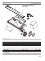
PRODUCT FEATURES
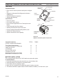
Make sure you have received all
parts:
Check your packing list to verify that all listed parts have
been received. You should have the following:
NB Models
• Unvented Gas Log Burner Assembly
• Two (2) Plastic Bags Containing Crushed Volcanic
Rock
• Installation/Operating Instructions
• Two (2) Anchoring Screws
• Ceramic Fiber Logs / Refractory Logs
• Rock wool & Bright Embers
• Grate Assembly
• On/Off Log Switch Assembly (MV Models Only)
• Thermostat Remote Control (SCR Models Only)
• ‘AA’ Batteries (SC Models only)
The following options may be used with the millivolt controlled heater. These options are not packaged with the
log set.
• Hand Held Remote with Receiver (MV)
• Wall Thermostat with 15' Wire
• Wall Switch with 15' Wire
Carefully inspect the contents for shipping damage. If any
parts are missing or damaged, immediately inform the
dealer from whom you purchased the appliance. Do not
attempt to install any part of the appliance unless you
have all parts in good condition.
What you will need for
installation:
You should have the following items available before proceeding with installation:
NB18/NB24 Gas Log Set
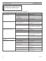
GAS pressures
Natural Propane (LP)
Inlet Minimum
5.0” w.c.
11.0” w.c.
Inlet Maximum
10.5” w.c. 13.0” w.c.
Regulator Pressure Setting 3.5” w.c.
11.0” w.c.
Pilot Regulator
3.5” w.c.
n/a
Gas Specifications
Gas Rate
Max.InputMin. Input
Model
Fuel
BTU/h BTU/h
NB18
Natural
28,000 19,000
NB24
Natural
37,000 25,000
NB18
LP
27,000 22,000
NB24
LP
36,000 28,000
Natural Gas
NOTE: An external regulator is required to reduce supply
pressure to a maximum of 10Z\x" w.c. on natural gas systems operating at higher pressure.
Propane/LPG
Note: An external regulator is required to reduce supply
pressure to a maximum of 13" w.c.
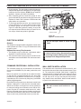
MILLIVOLT ignition controls
Piezo ignitor allows ignition of the pilot without the use of
matches or batteries.
Millivolt control has four (4) positions:
OFF - All gas to the gas logs is shut off at the
valve.
IGN - Valve position to light/maintain a standing pilot.
• External regulator (for propane/LPG and 1/2 psi
•
•
•
•
•
ON - Valve position to turn ON/OFF log set
with remote switch/thermostat.
LOW/HI - Variable position to control flame height
(heat output).
•
•
•
CAUTION
natural gas systems only)
Piping which complies with local codes
Sediment trap (recommended)
Screwdriver
Tee joint.
Pipe sealant approved for use with propane/LPG
(Resistant to sulfur compounds)
Drill with 5/32 masonry bit
Pipe wrench or appropriate size crescent wrench
set
Manual shutoff valve
Gloves are recommended when handling
ceramic fiber logs to prevent skin irritation
from loose fibers. Logs are fragile — handle
with care.
81D0107
SIGNATURE COMMAND CONTROLS
Refer to Page 28
Pilot/ODS
The gas log heater is fitted with a specially designed
safety pilot (ODS assembly) which senses the amount
of oxygen available in the room and shuts the gas log
heater off if the oxygen level begins to drop below
a satisfactory level. The pilot can only be relit when
adequate fresh air is available.
Thermal Generator
The millivolt gas log pilot is fitted with a millivolt
(thermopile) generator to provide power for remote
activation.
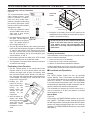
FIREPLACE and HEARTH DIMENSIONS
WARNING
NB18/NB24 Gas Log Set
This appliance is for installation only in a
solid-fuel burning masonry or UL127 factorybuilt fireplace, vent free appliance, or in
listed ventless firebox enclosure. It has been
design certified for these installations.
Exception: DO NOT install this appliance
in a factory-built fireplace that includes
instructions stating it has not been tested
or should not be used with unvented gas
logs.
Use manufacturer's installation and clearance requirements as defined in their manual.
The NB and NBSC/SCR Series unvented room heaters
are approved for installation into the following unvented
fireplaces:
VF Series Fireboxes, Magnum36/42, Lo-Rider36 or
BUF
The NB and NBSC/SCR Series unvented room heaters
may also be installed into a Ventless Firebox Enclosure for
Gas Fired Decorative Type Unvented Room Heaters per
ANSI Z21.91 (typically referred to as a "Universal Firebox"),
as long as firebox hearth dimensions meet the minimum
hearth dimensions shown below.
C
D
Important information for the
installation of this gas log set
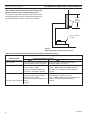
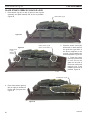
PLACEMENT IN FIREPLACE WITH A
RESTRICTIVE BARRIER
The following are guidelines for placing a gas log set in
a fireplace that has a restrictive barrier along the bottom
front opening of the fireplace. Some examples of barriers are glass/screen door frames and sunken/recessed
fireplaces.
Height of
Minimum Depth of
Restriction (x)
Fireplace/Firebox
No Restriction
13”
0” to 1Z\x”
16”
Greater than 1Z\x” to 3”
16”
Greater than 3”
*
*Any barrier greater than 3” placed in front of the gas log
set is not recommended by the manufacturer.
NOTE: Non combustible material such as refractory brick
may be used to line the floor of the fireplace in order to raise
the height of the gas log set in relation to a restrictive barrier.
If the unit is raised, the minimum height dimension listed in
the homeowner’s manual must not be exceeded.
NOTE: If the log set is equipped with a remote receiver, a
restrictive barrier may reduce the battery life by increasing
the ambient temperature inside the fireplace. Placement
of the receiver outside of the fireplace will extend the
battery life.
The log set should be
Glass door frames
with adjustable
louvers should have
the louvers fully
open while the unit
is in operation
placed against or as
near as possible to the
rear wall of the fireplace/
firebox.
A
B
Model
NB18 w/18” Log
NB24 w/24” Log
NB24 w/30” Log
NB18SC,SCR w/18” Log
NB24SC/SCR w/24” Log
NB24SC/SCR w/30” Log
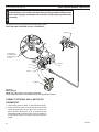
Figure 1 Minimum Hearth Dimensions
A
26”
29”
33”
28Z\x”
31”
35”
B
13”
13”
13”
13”
13”
13”
C
18”
22Z\v”
25Z\v”
20Z\v”
25Z\v”
25Z\v”
D
17”
17”
17”
17”
17”
17”
Height of restrictive barrier
caused by glass door frames,
recessed fireplaces, etc. from
the base or bottom surface of
the unit. (Refer to Table)
Figure 2 Reference Drawing of a Natural Flame Log
Set in an Enclosure
WARNING
FP2252
Depth of Fireplace/Firebox
Refer to Table
Barriers such
as the bottom of a glass door
FP2252
set in
in enclosure
frame placed
front of a gas log set can
change the air flow characteristics of the
fireplace which in turn can cause the unit to
overheat and malfunction.
81D0107
WARNING
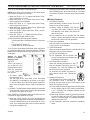
CLEARANCES and HEIGHT REQUIREMENTS
NB18/NB24 Gas Log Set
The dimensions shown in Figures 3 through 11 and defined in the
fireplace manufacturer's instructions are minimum clearances to
maintain when installing this heater. Left and right clearances are
determined when facing the front of the heater.
When heater is installed into a ventless firebox, minimum clearances,
as specified by the ventless firebox manufacturer, must be met.
Follow these instructions carefully to ensure safe installation. Failure
to follow instructions exactly can create a fire hazard.
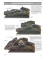
Sidewall and ceiling clearances: The sides of the fireplace opening must be at least 16" from any combustible
wall. The ceiling must be at least 42" from the top of the
fireplace opening.
42"
16"
Heat resistant material (minimum requirements) with
no wooden mantel or other combustible projection:
To install the gas logs into a fireplace with no wooden
mantel, shelf or other combustible projection above the
fireplace opening, measure the heat resistant material
height, according to Figure 4 and TABLE A.
Heat resistant materials such as slate and marble must be
at least 1/2” thick. Sheet metal should not be installed
onto combustible material.
IMPORTANT: If you cannot meet these minimum clearances you must operate the heater with chimney flue
damper open. Refer to “Installing Vented Applications”
found on Page 17.
Heat resistant
Material
Measure
This
Distance
Figure 3 Sidewall and Ceiling Clearances
Heater in
Fireplace/
Firebox
FP2254
Figure 4 Measure Heat Resistant Material
Table A - Heat Resistant Material Requirements with No Mantel or Combustible Projection
Heat Resistant Requirements for Safe Installation
FP2254
Material Measurement
NB18
NB24
measure heat resist
12” or more
Hood not required
Hood not required
8” or less than 12”
Hood not required
Extend heat resistant material to 12” or install hood. Figure 4
Less than 8”
Extend heat resistant Extend heat resistant material to 8” AND install hood.
material to 8” AND
Figure 5. OR, extend heat resistant material to a height of install hood. Figure 4
at least 12”
81D0107
NB18/NB24 Gas Log Set
CLEARANCES and HEIGHT REQUIREMENTS
Heat resistant material (minimum requirements) with
wooden mantel or other combustible projection:
To install the heater with a wooden mantel, shelf or other
combustible projection above, first measure the heat resistant material shown in Figure 5, then refer to Table B.
8” or More
of Heat
Resistant
Material
Hood
Heater in Fireplace
or Firebox
FP2255
Figure 5 Measuring Heat Resistant Material for Mantel
Table B - Heat Resistant Material Requirements Height and Mantel Location
Requirements for Safe Installation with Wooden Mantel, Shelf or
FP2255
Heat Resistant
other Combustible Projection
Material Measurement
NB18
NB24measure heat resist
12” or more
Hood not required. Observe profiles Hood not required. Observe profile (side (side elevations) shown in Figure 6 elevations shown on Figure 8
8” or less than 12”
Install hood and observe profiles Install hood and observe profiles shown in shown in Figure 7 OR Figure 7; OR extend heat resistant material
extend heat resistant material to
to at least 12” and observe profiles shown in at least 12” and observe profiles
Figure 8
Less than 8”
Extend heat resistant to at least 8”, Extend heat resistant material to least 8”, install
install hood and observe profiles
hood and observe profiles shown in
shown in Figure 7; OR
Figure 7; OR extend heat resistant material to at
extend heat resistant material to at least 12” and observe profiles shown in
12” and observe profiles shown in
Figure 8
Figure 6
81D0107
CLEARANCES and HEIGHT requirements
NB18/NB24 Gas Log Set
10" or less
10"
8"
6"
256O"
Heat
Resistant
Material
Heat
Resistant
Material
28"
12" min.
8" 14" 2056O" 246" 28"
Heater in
Fireplace or
Firebox
FP2256
Heater in
Fireplace or
Firebox
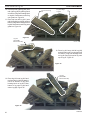
Figure 6 Minimum Mantel
Clearance with No
Hood - NB18
Example: A mantel may project from the wall a maximum
of 2Z\x" at a minimum of 14" above the opening, and a maximum of 6" at a minimum
of 20Z\x" above the opening.
FP2256
FP2260
Example: The bottom of the mantel may project from the
wall a maximum of 10" at a minimum of 28" above the
FP2260
opening.
min mantel 24
7"
6"
min. clearance no hood
12"
10"
8"
6"
Heat
Resistant
Material
Figure 8 Minimum Mantel
Clearance with No
Hood — NB24
Mantel
256O"
8" 1456O" 186" 2256O" 26"
Minimum
of 8” Heat
Resistant
Material
256O"
1456O"
4"
8"
Hood
Heater in
Fireplace or
Firebox
Figure 7 Minimum Mantel
Clearance with Hood
- All Models
FP2257
Example: A mantel may project from the wall a maximum
of 2Z\x" at a minimum of 8" above the opening, and a maximum of 6" at a minimum
of 14Z\x" above the opening.
FP2257
min clear with hood
FP2259
Hood
Figure 9 - Minimum Mantel
Clearance with Hood - NB24
(Example of Unsafe
Installation)
FP2259of an unsafe mantel installation.
Figure 9 is an example
wrong mantel clearance
This mantel projects
4" at 8" above the opening, exceeding
the maximum acceptable depth of 2Z\x” The mantel also
projects 7" at 14Z\x" above the opening, exceeding the
maximum acceptable depth of 6".
If your mantel profile is unsafe, you may either:
• Raise the mantel to an acceptable height
or
• Remove the mantel
81D0107
FLOOR CLEARANCE
NB18/NB24 Gas Log Set
The gas log heater must be installed at least 1C\," above any combustible flooring material, such
as carpeting or tile, which is closer than 14" to the base of the fireplace. The minimum distance
must be maintained from the top surface of carpeting, tile, etc. Figure 10
OR
The gas log heater may be installed nearer to the floor if a minimum of 14" of noncombustible
material such as slate or marble is installed between the base of the fireplace and the combustible flooring. Figure 11
Heater in Fireplace
or Firebox
Combustible
Material
1C\,” Minimum
FP2261
Figure 10 Minimum Clearance above Combustible Flooring
FP2261
Min comb floor clear
Heater in Fireplace
or Firebox
Combustible
Material
This Distance
May Now be
Less Than 1C\,”
14” Minimum
FP2262
Figure 11 FP2262
Minimum Clearance above Combustible
withfloor clearance
MinFlooring
noncomb
Noncombustible Material Installed at Base of Fireplace
10
81D0107
WARNING
WARNING
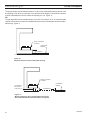
FIREPLACE PREPARATION
NB18/NB24 Gas Log Set
Before installing in a solid fuel burning fireplace, The chimney flue and
firebox must be cleaned of soot, creosote, ashes and loose paint by a
qualified chimney cleaner.
This appliance is for installation only in a solid fuel burning fireplace
(masonry fireplace or manufactured fireplace) with a working flue and
constructed of noncombustible material.
Exception: DO NOT install this appliance in a factory-built fireplace
that includes instructions stating that it has not been tested or should
not be used with unvented gas logs. This log set may be installed as a
vented log set.
Before fully installing the unit:
• Turn OFF the gas supply to the fireplace or firebox.
• Seal any fresh air vents and/or ash clean-out doors
located on the floor or wall of the fireplace. If left
unsealed, drafting may cause pilot outage or sooting. Use a heat resistant sealant. Do not seal the
chimney flue damper.
INSTALLING VENTED APPLICATIONS NB & NBSC ONLY
Install and operate the appliance as directed in this
manual.
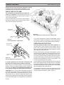
Damper stop installation
A damper stop must be provided with the unit. Contact your
dealer to obtain one. The damper stop must be installed as
shown in Figure 12 to prevent full closure of the fireplace
damper blade and provide a minimum 29 square inch flue
opening.
Manual and millivolt controlled gas logs may be installed
as a vented decorative log set in compliance with ANSI
Z21.60 and National Fuel Gas Code, Section 6.6. Since,
the gas logs are operated with the damper open, noncombustible material and minimum mantel requirements do not apply.
Before installing the appliance:
• Turn off gas supply to fireplace or firebox.
• Have the fireplace floor and chimney professionally
cleaned to remove ashes, soot, creosote or other
obstructions. Have this cleaning performed annually
after installation.
• Seal any fresh air vents or ash clean-out doors
located on floor or wall of fireplace. If not, drafting
may cause pilot outage or sooting. Use a heat-resistant sealant.
81D0107
Damper Stop
Damper
FP2263
Figure 12 Damper Stop Installation.
FP2263
Damper stop install
11
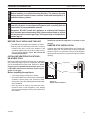
VENTED APPLICATION INSTALLATION / SECURE APPLIANCE
NB18/NB24 Gas Log Set
The fireplace and gas logs function as a
system. If the fireplace is spilling into the
room (check with a match or a smoke stick),
reposition the damper clamp until a positive
draft is obtained by opening the damper. If
negative pressure in home prevents having
a positive draft, contact your dealer for
assistance.
WARNING
WARNING
VENTED APPLICATIONS ONLY
You must secure the gas log heater to
the fireplace floor. If not, the entire unit
may move when you adjust the controls.
Movement of unit may cause shifting of
the gas logs which leads to sooting and
improper burning. Grate movement could
cause a gas leak.
Special care is required if you are installing
the unit into a sunken fireplace. You must
raise the fireplace floor to allow access to gas
log controls. This will insure adequate air flow
and guard against sooting. Raise the fireplace
floor using noncombustible materials, as
described in Placement in a Fireplace with
Restrictive Barrier on Page 6.
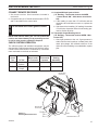
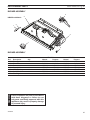
Assembly procedure
1. Center the gas log unit on the fireplace or firebox. Make certain the front of the burner sits
inside the front edge of the fireplace or firebox.
2. Anchor holes are located on the right and left sides of the unit. After centering the burner
correctly, mark the hole positions on the fireplace/firebox floor. Drill two (2) 5/32" diameter
holes approximately 1Z\x" deep.
3. Anchor the grate to the fireplace/firebox floor using the screws provided. Figure 13
Proper installation of the grate is essential to prevent any movement of the gas logs
and controls during operation.
Screw
Screw
FP2264
Figure 13 Securing Heater to Floor of Fireplace/Firebox
Anchor Hole
81D0107
12
FP2263
secure to floor
WARNING
gas line connection
NB18/NB24 Gas Log Set
Use new black iron or steel pipe. Internally tinned copper or copper
tubing can be used per National Fuel Code, section 2.6.3, providing gas
meets hydrogen sulfide limits, and where permitted by local codes. Gas
piping system must be sized to provide minimum inlet pressure (Listed
on Data Plate) at the maximum flow rate (BTU/hr). Undue pressure loss
will occur if the pipe is too small.
A manual shutoff valve must be installed upstream of the appliance.
Union tee and plugged 1/8" NPT pressure tapping point should be
installed upstream of the appliance. Figure 14
NOTICE: A qualified gas appliance installer must connect
the heater to the gas supply. Consult all local codes.
IMPORTANT: Hold heater valve firmly with a wrench to
prevent movement when connecting to inlet pipe.
Always use an external regulator for all propane/LPG
heaters and high pressure one to two-pound systems
only, to reduce the supply tank pressure to a maximum of
13” w.c. This is in addition to the internal regulator in the
heater valve.
To Heater
Valve
Pipe Coupling
Pipe
Stainless
Flexible Tube
Locations
that the
Pressure
Tapping
Point May Be
Installed
Gas
Supply
Inlet
Manual Shutoff
Valve
Test all gas joints from the gas meter to the heater valve
for leaks using a gas analyzer or soap and water solution
after completing connection. DO NOT USE AN OPEN
FLAME.
Check the gas pressure with the appliance burning and
the control set to HIGH.
Millivolt Valve Control
Figure 15
The valve regulator controls the burner pressure which
should be checked at the pressure test point.
Turn captured screw counter clockwise two or three turns
and then place tubing to pressure gauge over test point
(Use test point “OUT” closest to control knob). After taking
pressure reading, be sure and turn captured screw clockwise firmly to re-seal. Do not over torque. Check for gas
leaks.
WARNING
FP2265
CHECK
FP2265 GAS TYPE: The gas supply must
be
same as stated on the heater’s ratgas the
connection
ing plate. If the gas supply is different, DO
NOT INSTALL THE HEATER. Contact your
dealer for the correct model.
Connecting directly to an unregulated propane/LPG tank can cause an explosion.
81D0107
When tightening up the joint to the valve, hold the valve
securely to prevent movement.
Test Port “OUT”
WARNING
Figure 14 Gas Connection
The heater gas inlet connection is a 3/8" NPT at the valve.
On all control type units, the inlet connection is on the right
side of unit. To connect from the opposite side, route the
pipe around the back portion of the unit.
FP2266
Figure 15 Pressure Test Point Location
Millivolt Control
FP2266
valve
13
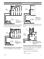
ELECTRICAL WIRING - Millivolt
CAUTION
NB18/NB24 Gas Log Set
Label all wires prior to disconnection when servicing controls. Wiring errors
can cause improper and dangerous operation. Verify proper operation after
servicing.
The millivolt valve is a self-powered combination gas control
that does not require 110 Vac to operate.
ODS Pilot
ODS
Pilot
On/Off Switch
or Optional Wall
Switch, Remote
or T-Stat
Millivolt
Valve
TH = 3
TP = 1
TP/TH = 2
Log Switch
Figure 16 Wiring Diagram
NOTE: Log switch wires are not factory connected.
Connect log switch wires to the TH/TP and TH valve terminals as shown.
Connect Optional Wall Switch or
Thermostat
FP2267
1. Use 18 awg, two-wire cable, 15 feet maximum length.
wiring diagram
2. At one end of the cable, connect both wires to the wall
switch or thermostat. At the other end, connect one
wire to TP/TH and one wire to TH, or connect the wall
switch/thermostat to the two male (0.25") terminals on
the left side of the unit. The color of the wires does not
matter.
14
81D0107
ELECTRICAL WIRING - Millivolt
NB18/NB24 Gas Log Set
Connect Remote Receiver
A.Complete Millivolt System Check
NOTICE
1. Set remote receiver. See instructions included in
receiver kit.
2. Connect the two (2) 1/4" female connectors to the TP/TH
and TH terminals on the control valve.
Do not allow wires touch grate or burner.
NOTE: Heat reduces battery life. You can protect the
receiver and extend battery life by mounting receiver
in wall or other location outside the fireplace.
Check System Operation
The millivolt system and individual components may be
checked with a millivolt meter having a 0-1000 mV range.
Conduct each check shown in chart below by connection
meter test leads to terminals as indicated.
Check
Test
To Test
A
Complete
System
B
Thermopile
Output
(“A” Reading - Thermostat contacts CLOSED
- Control Knob “ON” - Main burner should turn
ON)
a. If the reading is more than 175 millivolts and the
automatic valve still does not come on, replace the
control.
b. If the closed circuit reading (“A” reading) is less than
175 millivolts, determine cause for low reading, proceed to Section B below.
B.Thermopile Output Reading Check
(“B” Reading - Thermostat contacts OPEN - Main
burner OFF)
1. Check gas pressure to the unit. If gas pressure is
within minimum and maximum on data plate, then
check pilot voltage, 500 millivolts minimum. If the
minimum millivolt reading is not obtainable, replace
pilot.
Connect
Meter Leads
To Terminals
2 & 3
Switch or
Thermostat
Contacts
Closed
Meter
Reading
Should Be
Minimum 175
1 & 2
Open
Minimum 500
Remote Wire
Connectors
Remote Wire
Connectors
Figure 17 Installing Remote Receiver
81D0107
FP2268
TP/TH = 2
TP = 1
TH = 3
Valve
Remote Receiver
FP2268
remote receiver
15
final installation
WARNING
NB18/NB24 Gas Log Set
The positioning of the logs is critical to the safe and clean operation of
this heater. Sooting and other problems may result if the logs are not
properly and firmly positioned in the appliance. Never add additional logs
or embellishments such as pine cones, vermiculite or rock wool to the
heater. Only use the logs and 2G-RW rock wool (for NB18), or 3G-RW rock
wool (for NB24) supplied with the unit.
Failure to position the parts in accordance with diagrams below or to use
only parts specifically approved for this heater may result in property
damage or personal injury.
Before you begin — This unit is supplied with seven (7)
ceramic fiber logs. Do not handle these logs with your bare
hands. Always wear gloves to prevent skin irritation
from ceramic fibers. After handling the logs, wash your
hands gently with soap and water to remove any traces
of fibers.
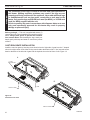
Cast Iron Grate Installation
Install the cast iron grate by inserting screw head on back of right side of grate into the “I” shaped
slot on front right corner of unit. After moving screw head to the bottom of the “I” slot, insert the screw
head on the back of the left side of grate into the keyhole slot on the left front of unit. Figure 18
A.
Key
Hole Slot
B.
I Slot
Cast Iron Grate
Figure 18 FP2270
Install Cast Iron Grate
install grate
Cast Iron Grate
16
FP2271
81D0107
LOG PLACEMENT
NB18/NB24 Gas Log Set
Before installing logs, place rockwool in dime size pieces
evenly over small burner ports starting in the rear of the
burner going towards the front. Avoid placing rock wool on
slots on each side of rear burner and on large yellow flame
ports on front of burner. After covering small burner ports,
discard any excess rock wool.
WARNING
Rock Wool placement
Wash hands after placing rock wool. Itching may occur.
Note: Installation instructions are the same for 18",
24", and 30" log sets. Pictures used in this manual
illustrate the 24" set. Some variation may exist between
the images and the set included with this manual.
Install 18", 24" and 30" (F,R) Berkley
OAK logs on Natural blaze Burner
• Use only rock wool provided with log
set.
• Do not add additional rock wool.
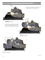
1. Place the #1 log (the “chunk”) on the grate bar right side
of the burner adjacent to the controls. Figure 20
2. Place front right log (#2) on right pin located on burner
and right grate bar. Figure 21. slide Log #1 forward so
that it is tight against log #2.
Ember Chunk
Log #1
Dime-sized Pieces
of Rock Wool
FP2269
Figure 19 Place Rock Wool
Figure 20 Place Ember Chunk Log #1
LG620
LG620
place log 1
Right Front
Log #2
FP2269
place rock wool
3. Place right rear log (#3) on pin located
on rear support bracket and rest left side
of log on front right log. Figure 22.
LG630
Figure 21 Place Right Front Log #2
81D0107
LG630
NB18/24 log 2
17
LOG PLACEMENT
NB18/NB24 Gas Log Set
Right Rear
Log #3
4. Place left rear log (#4) on pin located on rear
support bracket on left side. Figure 23
LG631
Left Rear
Log #4
Figure 22 Place Right Rear Log #3
LG631
5. Place left front logNB18
(#5)24
onLog
left3pin located
on burner and left grate bar. Rest top right
portion of log on right front log. Figure
LG632
Figure 23 Place Left Rear Log #4
Left Front Log #5
LG632
NB18 24 Log 4
24
LG633
Figure 24 Place Left Front Log #5
18
LG633
NB18 24 Log 5
81D0107
LOG PLACEMENT
NB18/NB24 Gas Log Set
Middle Left
Log #6
6. Place top left log (#6) on unit by
placing grooved portion of log onto
left grate bar with bark facing outward. Rest front part of log in groove
on left front log. Figure 25
Figure 25 Place Middle Left Log #6
LG634
Left Top
Log #7
Right Top
Log #8
7. Place left top log (#7) on left rear log
(#4) and left front log (#5) using locating
grooves on bottom of #7 LG634
and locating
NB18 24 log 6
blocks on logs #4 and #5. Figure 26
8. Place right top log (#8) onto right rear
(#3) and right front (#2) logs using locator
on bottom of right top log. Figure 26
PLACE FLICKERING EMBERS
Place flickering bright embers (FBE-.1G)
after placing logs on burner. Pull apart into
small strands and place on top of existing
rock wool in front of and between front logs
where they can be seen. Try to avoid stacking these embers on top of each other. Use
smaller and stringier strands for maximum
effect. Use as much as needed until desired
effect is achieved.
Figure 26 Place Right Top Log #8
LG636
LG636 the decorative rock
PlacE
CAUTION
NB 18 24 log 8
DO NOT sprinkle volcanic rock on the logs,
around the pilot, or on or near burners. This
may cause sooting. Place volcanic rock only
on the floor of the fireplace.
During initial operation of the new heater,
new burning logs and/or rock wool will give
off a paper burning smell and orange flames
will be present. Simply open the windows for
a few hours to vent the odor.
Figure 27 Place embers
19
81D0107
810107
NB18/24 cover
LOG PLACEMENT
NB18/NB24 Gas Log Set
PLACE STONEY CREEK SC18/24/30-R LOGS
1. Place bottom log (#1) on two (2) pins on rear of grate
assembly and push towards rear as far as possible.
Figure 28
Bottom Rear Log #1
Figure 28
LG1065
2. Place the ember chunk (#2)
with notch on both ends on
the grate bar right side of
the burner adjacent to the
controls. Push towards rear
LG1065
as far as possible. Figure 29
Mon SC24R log 1
3. Place the ember
chunk (#3) with notch
on one end on the
grate bar left side of
the burner with notch
towards rear. Push
towards rear as far as
possible. Figure 29
Ember Chunk Log #2
(Notch on both ends)
Figure 29
Ember Chunk
Log #3
(Notch on
one end)
LG1066
Front Bottom Log #4
4. Place front bottom right log
(#4) on right pin located on
burner and right grate bar.
Figure 30
LG1066
Mon SC24R logs 2 3
LG1067
Figure 30
20
LG1067
Mon SC24R log 4
81D0107
LOG PLACEMENT
NB18/NB24 Gas Log Set
5. Place front bottom left log (#5) on
left pin located on burner and left
grate bar. The right side of the log
should rest on log #4. Figure 31
6. Place mid right log (#6) on bottom
rear log (#1) and front bottom
right log (#4) by placing notch on
bottom of log on locating block on
log #1. Place front of log in notch
of log #4. Figure 31
Mid Right Log #6
Front Bottom Left
Log #5
Figure 31
LG1068
Mid Rear Log #7
LG1068
7. Place mid rear log Mon
(#7) on
SC24R
logs
Figure
32 5 6
bottom rear log (#1) and mid
right log (#6) by placing notch on
bottom of log onto locating block
on log #1. Right side of log will
rest on log #6. Figure 32
LG1069
Center Log #9
Mid Left Log #8
Figure 33
8. Place mid left log (#8) on mid rear
log (#7) and front bottom log (#5) by
LG1069
placing notches on bottom of log onto
Mon SC24R log 7
locating blocks on log #7 and log #5.
Figure 33
9. Place center log (#9) onto
front bottom left log (#5)
by placing notch on
bottom of log #9 onto
locating block on log
#5. The flat triangleshaped end of log #9
should be towards
front with pointed
end of log resting on
bottom rear log (#1).
Figure 33
LG1070
81D0107
LG1070
Mon SC24R logs 8 9
21
LOG PLACEMENT
NB18/NB24 Gas Log Set
10. Place top front right log (#10) onto
mid right log (#6) by placing notch
on bottom of log onto locating block
on log #6. Rest bottom end of log
onto grate bar. Figure 34
11. Place top front left log (#11) onto
mid left log (#8) by placing notch on
bottom of log onto locating block on
log #8. Rest bottom end of log onto
grate bar. Figure 34
Top Front Left Log
#11
Top Front Right
Log #10
Figure 34
Log #12
(SC2430EK
Enhancement Kit)
LG1071
12. Place log #12 onto mid left log (#8)
LG1071
Mon SC24R logs 10and
11 mid rear log (#7) by placing notch
on bottom of log onto locating block
on log #8. Rest right end of log onto
top of log #7. Figure 35
Figure 35
LG1072
LG1072
13. Place log #13 onto log #12
and
SC24R log 12
top front right log (#10) byMon
placing
notch on bottom of log onto
locating block on log #12. Rest
bottom of log onto log #10 and
center log (#9). Figure 36
Log #13
(SC2430EK
Enhancement Kit)
Figure 36
22
81D0107
FLAME APPEARANCE
NB18/NB24 Gas Log Set
Flames from the pilot and burner should be visually
checked as soon as the heater is installed. In addition,
periodically check the flames visually during operation.
Check the pilot flame
The pilot flame must always be present when the
heater is in operation. It should just touch the top
of the thermocouple tip for natural. Refer to Figure
37 for correct pilot flame.
If the pilot flame does not touch the thermocouple,
then the main burner cannot function reliably. Figure
38 for incorrect shape of pilot flame.
Thermocouple
for Natural
Figure 39 Correct Appearance of Rear Flames for Berkley Oak
Thermocouple
for LP
Figure 37 Correct Appearance of Pilot Flame
log. If flame impingement cannot be eliminated, contact
your installer or dealer for assistance. Flame impingement
on logs may create soot and possible property damage.
OPERATING INSTRUCTIONS
Thermocouple
for Natural
FP2272
pilot correct flame
Thermocouple
for LP
Figure 38 Incorrect Appearance of Pilot Flame
In normal operation at full rate after 15 minutes, the
following flame appearances should be observed:
Burner will have a random pattern of yellow flames as
shown in Figure 39. There should be glowing embers on
the front burner. NOTE: The front flames and embers will
be an opaque orange color during the burn off time.
FP2273
CAUTION: After a 15 minute pre-heat period, observe all
pilot bad flame
yellow flames to ensure there is no impingement with any
Avoid any drafts that alter burner flame patterns. Do
not allow fans to blow directly into the fireplace. Do not
place a blower inside the burn area of the firebox. Ceiling
fans may create drafts that alter flame patterns. Sooting
and improper burning will result.
During manufacturing, fabricating and shipping, various
components of this appliance are treated with certain oils,
films or bonding agents. These chemicals are not harmful, but may produce annoying smoke and smells as they
are burned off during the initial operation of the appliance,
possibly causing headaches or eye or lung irritation. This
is a normal and temporary occurrence.
The initial break-in operation should last four hours with the
burner at the highest setting. Provide maximum ventilation
by opening windows or doors to allow odors to dissipate.
Any odors remaining after this initial break-in will be slight
and will disappear with continued use.
This appliance must not be used with glass doors in the
closed position. This can lead to pilot outages and severe
sooting outside the fireplace. Page 6, Figure 2
log. If any yellow flame is contacting any log, turn off log
set and allow to cool. Remove all logs and carefully reinstall following log placement instructions precisely. Relight
burner and check again for impingement of any flame on
81D0107
23
OPERATING INSTRUCTIONS - MILLIVOLT
NB18/NB24 Gas Log Set
WARNING
for your safety read before lighting
If you do not follow these instruction exactly, a
fire or explosion may result causing property
damage, personal injury or loss of life.
A. This appliance is equipped with a piezo ignition device which lights the pilot. If piezo is not working
properly see Match Lighting Instructions, Page 26.
B. BEFORE OPERATING smell all around the appliance area for gas. Be sure to smell next to the floor
because some gas is heavier than air and will settle on the floor.
WHAT TO DO IF YOU SMELL GAS:
• Do not attempt to light any appliance.
• Do not touch any electric switch; do not use any phone in your building.
• Immediately call your gas supplier from a neighbor's phone. Follow the gas supplier's instructions.
• If you cannot reach your gas supplier, call the fire department.
C. Use only your hand to push in, or turn the gas control knob. Never use tools. If the knob will not push
in or turn by hand, don't try to repair it. Call a qualified service technician. Force or attempted repair
may result in a fire or explosion.
D. Do not use this appliance if any part of it has been under water. Immediately call a qualified service
technician to inspect the appliance and to replace any part of the control system and any gas control
that has been under water.
Pilot
Piezo Ignitor
Hi/Lo Knob
On/Off/Pilot Knob
FP2274
Location of Piezo Ignitor, Control Knobs and Switch
Switch
FP2274
NB burner
24
81D0107
OPERATING INSTRUCTIONS - MILLIVOLT
NB18/NB24 Gas Log Set
MILLIVOLT CONTROL LIGHTING INSTRUCTIONS
1. STOP! Read the safety information label.
2. Make sure the manual shutoff valve is fully open.
3. This gas log set is equipped with an ignition device (piezo) which automatically lights the pilot. If
piezo ignitor does not light the pilot, refer to instructions for Match Lighting Instructions, Page 26.
4. Turn gas control knob clockwise
to the OFF position and turn ON/OFF switch to OFF position.
5. Wait (5) minutes to clear out any gas. Then smell for gas, including near the floor. If you smell gas,
STOP! Follow the instructions under What To Do If You Smell Gas, Page 24.
6. From OFF position, turn the gas control knob counterclockwise
to IGN position. Push in control
knob for 5 seconds. NOTE: If you are running the heater for the first time, it may be necessary to press in the control knob for 30 seconds or longer to allow air to bleed out of the gas
piping.
7. With the control knob pushed in, push in and release the piezo ignitor button to light the pilot.
8. Continue pushing the control knob in for a further 60 seconds to prevent the flame detector from
shutting off the gas while the probe is warming up. Release the control knob.
9. Turn gas control knob counterclockwise
to the ON position.
10. After the pilot has been lit for one minute, the burners can be turned on. Turn the ON/OFF switch to
ON position.
11. If the gas logs will not operate, follow the instructions To Turn Off Gas To Heater below and call your
service technician or gas supplier.
Pilot
Piezo Ignitor
Hi/Lo Knob
On/Off/Pilot Knob
Pilot
Switch
Controls
FP2274
NB burner
TO TURN OFF GAS TO HEATER
1. Turn control knob clockwise
to OFF position to completely shut off the heater.
2. If applicable: Turn ON/OFF switch to OFF position and/or set thermostat (if present) to lowest setting.
3. If applicable: Turn off all electric power to the heater.
81D0107
25
NB18/NB24 Gas Log Set
OPERATING INSTRUCTIONS - MILLIVOLT
MATCH LIGHTING INSTRUCTIONS
1. Remove any items necessary for easy access to the pilot (for example: logs, screens, etc.).
2. Follow appropriate lighting instructions found previously. Instead of pushing and releasing the piezo
button, light a match and hold the flame to the end of the pilot and ignite the pilot.
3. After control knob has been released and pilot stays lit, reinstall any items that were removed for pilot
access.
4. Call a qualified service technician for repair or replacement of the piezo ignitor.
26
81D0107
CHECK GAS PRESSURE & ELECTRICAL INSTALLATION - SIGNATURE NB18/NB24
COMMANDGas Log Set
1. Check gas type. The gas supply must be the same as
stated on the appliance’s rating decal. If the gas supply
is different from the fireplace, STOP! Do not install the
appliance. Contact your dealer immediately.
2. After completing gas line connection, purge air from
gas line and test all gas joints from the gas meter to the
fireplace for leaks. Use a solution of 50/50 water and
soap solution or a gas sniffer.
3. To check gas pressures at valve, turn captured screw
counter clockwise 2 or 3 turns and then place tubing
to pressure gauge over test point. Turn unit to high.
Figure 40. After taking pressure reading, be sure and
turn captured screw clockwise firmly to reseal. Do not
over torque. Check test points for gas leaks.
Pressure Inlet
FP1909a
Pressure Outlet
Figure 40 Signature Command Valve
WARNING
Do not FP1909a
use open flame to check for gas
leaks.
1. This fireplace may be used with a wall switch and/or
Signature Command wireless controls.
2. The command center control may be mounted on the
wall with the use of the SCSWEK 15ft. wall mount extension kit.
CAUTION
Electrical Wiring
Label all wires before disconnecting when
servicing controls. Wiring errors can cause
improper and dangerous operation.
COMMAND CENTER WALL INSTALLATION
WALL SWITCH INSTALLATION
This fireplace is equipped with the Signature Control valve
which operates on 6 volts. Four (4) “AA” batteries are used
to power control.
Optional Accessory Requirements
The command center may be mounted on the wall with
the use of the SCSWEK Kit (15ft. cable, junction box, wall
cover).
Mount the junction box provided at the desired location
on the wall. Do not extend beyond the 15 ft. wire cable
provided. If a longer distance is required, the 15 ft. may be
extended up to 30 ft. maximum by using two (2) SCSWEK
cables plugged together.
Route the wire from junction box to the burner control in the
fireplace. Unplug the 12" cable from the command center.
Attach the connector to the pins from wire by pushing in
to connector making sure to follow the color code on connector. Plug the 15 ft. extension cable into the 2 ft. cable.
Remove command center from the fireplace and plug the
other end of the extension cable into the command center.
Snap on wall cover provided and screw to junction box.
81D0107
signature command valve
alternate view
8/08
The wall switch wire connection is located off the 2 ft. wire
harness from the control box to the command center. Figure
41. The connection is labeled “Wall Switch”. Unplug the
male and female connectors and connect the two (2) low
voltage wires not provided. Run wire to desired location
on wall. Up to 50 ft. of 18 ga. wire may be used if necessary. Attach wires to wall switch. Mount the wall switch in
to junction box and screw on cover.
WARNING
General
Do not connect wall switch to 110 V
circuit.
27
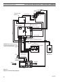
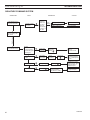
ELECTRICAL INSTALLATION - SIGNATURE COMMAND
NB18/NB24 Gas Log Set
Thermocouple
Module
Thermocouple
Pilot
Orange
RF Receiver
ON/OFF Button
Control Board
Yellow
Black / Thermopile
Red / Thermopile
Black
Sensor
Ignitor / Sparker
Plug-in Connector
Control Board to Command Center
Red
OFF/LO
NOTE: Wall switch wires must
be connected together if a wall
switch is not being used.
Ground
Plug-in Connector
Stepper Motor to
Control Board
LED
ON/HI
Master Switch
Command Center
Optional
Wall Switch
DC Power/Green
Plug-in Connector
Control Board to
Solenoid
Gas Out
Gas In
Pilot Gas Tubing
Figure 41 Signature Command Wiring Diagram
28
fp2701
SCS 2 wire wiring
Valve
81D0107
OPERATING INSTRUCTIONS - SIGNATURE COMMAND
NB18/NB24 Gas Log Set
WARNING
for your safety read before lighting
If you do not follow these instruction
exactly, a fire or explosion may result
causing property damage, personal
injury or loss of life.
A. This appliance is equipped with an ignition device which automatically lights the pilot. Refer
to the instructions.
B. BEFORE OPERATING smell all around the appliance area for gas. Be sure to smell next to
the floor because some gas is heavier than air and will settle on the floor.
WHAT TO DO IF YOU SMELL GAS:
• Do not attempt to light any appliance.
• Do not touch any electric switch; do not use any phone in your building.
• Immediately call your gas supplier from a neighbor's phone. Follow the gas supplier's
instructions.
• If you cannot reach your gas supplier, call the fire department.
C. Use only your finger to push in the master switch. Never use tools. If the switch will not function
by hand, do not try to repair it. Call a qualified service technician. Force or attempted repair
may result in a fire or explosion.
D. Do not use this appliance if any part of it has been under water. Immediately call a qualified
service technician to inspect the appliance and to replace any part of the control system and
any gas control that has been under water.
81D0107
29
OPERATING INSTRUCTIONS - SIGNATURE COMMAND
NB18/NB24 Gas Log Set
OPERATing INSTRUCTIONS
1. STOP! Read the safety information above.
2. This appliance is equipped with an ignition device which automatically lights the burner. Do not try
to light the burner by hand.
3. With five (5) minutes to clear out any gas. Then smell for gas, including near the floor. If you smell
gas, STOP! Follow "B" in the safety information on Page 29. If you do not smell gas, go to next
step.
4. Press the master switch to the "ON" (-) position. Within eight (8) seconds it will beep once. This
indicates the system is ready.
5. Press "ON " button. Sparker will spark and pilot flame will light.
6. Once pilot flame is established, the main burner flame will light automatically.
7. If the pilot will not stay lit after several tries, turn the master switch to "OFF" and call your service
technician or gas supplier.
OFF
OFF
ON
Master
Switch
ON
Command Center
FP1913
TO TURN
OFF GAS TO APPLIANCE
Switch
box
8/08
1. Turn master switch to "OFF".
2. Turn off all electrical power to the appliance if service is to be performed.
30
81D0107
SIGNATURE COMMAND SYSTEM OPERATION INSTRUCTIONS
FEATURES
NB18/NB24 Gas Log Set
To Thermopile
RF Receiver
ON/OFF
Command Center
To Sensor
• Easy Access Function Operation and System Configuration
• Operation Confirmation/Fault Diagnostic Indications
(LED/Buzzer)
• ON/OFF/HI/Med/Low Operation
• Optional Wall Mounting
Control Board
To Sparker
NG/LP
Conversion
Control
Board
• Electronic Ignition
• Pilot Lockout safety feature
• Electric Power Regeneration from Thermopile to save
•
•
•
•
•
battery
6-hour Automatic Shut Down Option
Standing Pilot/Intermittent pilot Conversion
Previous settings Restoration Ability (Memory Off)
ON/OFF RF Remote Receiver
Optional Transmitter Learn Capability
To Command
Center
To Stepper Motor
LED
OFF
Command
Center
To Valve
ON
Master Switch
Battery Door
Figure 42 Signature Command System Components
Transmitter (Options)
(TSTSC is supplied with R-Models)
Three Flame Height Settings
Low battery Indication for Transmitter Child Proof Lock-out
LCD Backlight
Security Codes 10,000
Countdown 6 hr Timer
Standard Thermostatic Control Mode
Smart Mode® Thermostat (Auto Flame)
TSTSC
TSMSC
X
X
X
X
X
X
X
X
X
X
X
X
X
X
---
FP1917
Signature components
8/08
BATTERY INSTALLATION
The Command Center uses four (4) "AA" batteries to operate the system.
To Install Batteries:
1. Press down the battery door tabs and pull out to remove battery door.
2. Install the batteries as indicated on Command Center.
3. Close battery door by snapping in place.
4. When the four (4) batteries are installed the system is ready to operate.
5. The batteries should be replaced when the LED indicates low battery or at least once a year.
81D0107
31
NB18/NB24 Gas Log Set
SIGNATURE COMMAND SYSTEM OPERATION INSTRUCTIONS
SYSTEM CONFIGURATION/SETUP
All System configuration/setup is done on the Command Center.
NOTE: When using On/Off wall switch, the switch must be in the ON position to perform all configuration set ups
at the command center.
Intermittent/Standing Pilot Setup (Default intermittent)
1. Holding the ON button on the Command Center while turning on the master switch will toggle between standing
pilot and intermittent pilot.
2. After the above operation, one beep (for standing pilot) or two beeps (for intermittent pilot) will be given as confirmation.
Six-hour Safety Shutdown Option (Default ON)
1. The system comes preset from the factory with a six (6) hour shutdown from its last command of operation. This is
done to prevent the fireplace from continuing to operate if unattended. You may disable this feature if you wish.
NOTE: By disabling this feature, your fireplace may continue to operate unattended.
2. When the master switch is in the ON position (“-”), pressing the ON button and the OFF button on the Command
Center simultaneously will toggle between enabling and disabling the six-hour shutdown option.
3. After the above operation, one beep (for enabling the six-hour shutdown option) or two beeps (for disabling the
six-hour shutdown option) will be given as confirmation.
Remote Transmitter Learn Function (Default OFF; unless packed with remote default will be on)
1. The RF receiver button located on the Control Board must be in the on position before the learn function can
begin. Use paper clip to depress button. One beep for RF receiver ON or two beeps for RF receiver OFF will be
given as confirmation. Refer to Figure 42 for location.
2. After the RF receiver is on, holding the OFF button on the Command Center while turning on the master switch
will activate the learn function for the transmitter.
3. After the above operation, two beeps will be given and the green LED on the Command Center will flash for 10
seconds.
4. During the 10 seconds, press the OFF button on a transmitter to learn. Another two beeps will be given to confirm
a successful learning. Refer to transmitter instructions for remote operations.
Shutting Off the Standing Pilot (Temporary Shut Off)
To shut off the standing pilot for service or summer shut down, press and hold the ON button on the Command
Center for 3 seconds when the master switch is in the ON position (“-”) and the main burner is off.
Note: Pilot will resume the next time system is turned on.
Key Combinations for System Settings
NOTE: When On/Off wall switch is used, it must be in the On position to perform all system setups.
Function
Intermittent/Standing
Pilot Setup
Standing Pilot Temp.
Shutoff
RF Remote Receiver
On/Off
Learn Remote
Transmitter
6-hour safety shutdown setup
32
Operation
Hold the ON ▲ button while turning on the master switch
(Beep once for standing pilot, twice for intermittent pilot)
Hold the ON ▲ button 3 seconds (when the master switch
on the main burner is off)
Push the RF receiver On/Off button on the control board
Beep once for ON and beep twice for OFF
Hold the OFF ▼ button while turning on the master switch
(Beep twice then press any handheld remote button)
Press the ON ▲ button and OFF ▼ button simultaneously
(Beep once for ON, twice for OFF)
Default Setting
Intermittent
Pilot
RF OFF
ON
81D0107
SIGNATURE COMMAND SYSTEM OPERATION INSTRUCTIONS
NB18/NB24 Gas Log Set
FUNCTIONS/OPERATION (from the Command Center)
Turning on the fireplace
1. Turn on the master switch and wait for a beep.
2. Press the ON button on the Command Center or turn on wall switch. Pilot will light and burner will come on High setting or last memory setting (See Turning Off Fireplace below). For memory feature.
Pilot Safety Lockout Function
1. If the pilot doesn’t light after sparking for 30 seconds, pilot trial lockout happens. The LED on the Command Center
flashes Green once every 2 seconds, until reset.
2. If the pilot flame is lost during normal operation, the system will try three (3) times to relight after three (3) failures, flame
loss lockout happens. The LED on the Command Center flashes Red-Green once every 2 seconds, until reset.
3. Turning the master switch on the Command Center to the off position, then ON again will reset the system.
Flame Height Control
1. Press the ON button (on the Command Center) once to turn on the main burner with maximum flame height.
2. Press the OFF button to decrease flame height. The first two presses will decrease the flame height to medium and
low.
3. The third press on OFF will turn off the main burner. In standing pilot configuration, the pilot will stay; in intermittent
pilot configuration, the pilot will be shut off.
Turning the Fireplace Off
There are three ways to turn the fireplace off.
1. Flip the master switch to the off (“O”) position. (This will turn the entire system OFF.)
2. Press the OFF button to Medium, Low, then Off.
3. Hold the OFF button anytime for three seconds or by turning off the wall switch. These two commands of OFF are
(Memory Off) the system will remember all last settings before turning off. The next time the fireplace is turned on, all
settings will resume. To reset, change to the desired settings and shut off by using the Memory Off commands and
the system will be reset to those new settings.
NOTE: After turning off there may be up to a two (2) minute delay before the burner can be relit. There will be three
(3) red flashes if the on button is pressed before the safety control is automatically reset.
Command Center Operations:
The following functions are available on the Command Center.
Function
Power Up
Fireplace ON
Fireplace OFF
Flame Height Up
Flame Height Down
Operation
Flip the master switch to the ON ("_") position to power up the system
Press the ON ▲ button on the Command Center or turn on wall switch to turn the fireplace on
Flip the master switch to the OFF ("o") position OR press the OFF ▼ button 3 times OR for Memory Off, hold the OFF ▼ button 3 seconds, or turn off wall switch
Press the ON ▲ button once to turn on the fireplace with maximum flame height
Press the OFF ▼ button to lower the flame height to Medium and Low
Self Diagnostics Chart:
The Command Center has a self-diagnostic LED enabling you to troubleshoot problems and potentially avoid a service call. Please refer to the charts below for indicator reference.
81D0107
Fault
Conversion Cover Missing
Spark Fail
No Sensor Signal or 2 min. safety
Pilot Lockout - trial
Pilot Lockout - flame loss
Low Battery
No or Low Thermopile Power
Learning
AC Power On
Pressure Switch Failed (Power Vent only)
LED Indication
One RED (1 time)
Two RED (1 time)
Three RED (1 time)
One GREEN, every 2 sec. (until manual reset)
One RED-GREEN, every 2 sec. (until manual reset)
One RED, every 10s (continuously)
Two RED, every 10s (continuously)
GREEN Flashes, every 1 sec. (for 10 sec.)
GREEN solid
One RED every 2 sec. (until manual reset)
33
Figure 43 shows the display of the TSTSC LCD.
Logo
Bar
n Function Areas of the LCD Display
Adjustment
Controls
Turn appliance OFF (at the master switch) if you
are away from your house for an extended period of time. Never leave anything on top of the
surface of the transmitter.
Menus
Due to the sensitive temperature monitoring
components in the transmitter, it is necessary
to allow the transmitter to stabilize to room temperature before accurate room temperatures
are displayed. If the transmitter is activated
from a severe cold condition, allow 15 minutes
for accurate temperature readings to appear on
the LCD display.
Touch Area
WARNING
TOUCH SCREEN REMOTE CONTROL OPERATION - SCR MODELS
Information
Bar
NOTE
NB18/NB24 Gas Log Set
Function Areas of the LCD Display
Information Bar
Figure 43
The information bar shows the room temperature, the
“sending signal” radio icon, the low battery indication icon,
the child-proof icon, and the flame icon. This area doesn’t
have touch buttons.
The Logo Bar contains the brand logo: Signature Command.
• The room temperature will always be shown after
•
•
•
•
power-up. It displays the room temperature from 40
°F to 99 °F. “Lo” and “HI” will be displayed when the
room temperature is lower than 40°F or higher than
99°F, respectively.
The radio icon will be shown when the transmitter is
sending a signal.
The low battery indication icon will be shown when
the battery voltage is low.
The child-proof icon will be shown when the childproof mode is activated.
The flame icon indicates the current flame height
- Off, Low, Medium and High
Touch Area
The touch area contains all touch buttons to control the
transmitter. It consists of two categories: menus and adjustment arrows. The blue LED backlight lights up for 8
seconds when any of the touch buttons is pressed.
• The menus include TIMER and THERMO buttons.
• The adjustment arrows include ON/up and OFF/
down. Their default function is to turn on/off the
flame. When a button from the menu is pressed,
the ON/up and OFF/down buttons will temporarily
become adjustment controls for the selected item.
When the adjustment is done, the ON/up and OFF/
down buttons go back to flame controller again.
34
Logo Bar
FP2660
n Initialization and
Setting up
TSTSC display
Installing Batteries
Figure 35
The remote transmitter has two
battery compartments, one on
each end of the transmitter. Always change all four (4) batteries at the same time.
Battery
Door
Tabs
Figure 44
To install batteries,
1. Press down the battery door
tab and pull out to remove the battery door.
2. Install the batteries as indicatedFP2607
inside the battery
compartments.
install battery
3. Close the battery door by snapping in place.
4. When all four batteries are installed, the transmitter
will initialize for 5 seconds and then is ready for use.
5. The batteries should be replaced every 12 months or
when the low battery icon indicator is displayed.
Changing Temperature Unit
When batteries are installed in the transmitter,
1. All available icons on the LCD will be turned on then
be cleared.
2. The LCD will display temperature unit: °F. Use ON ∆
to toggle the units between °F and °C within the first 5
seconds.
3. The transmitter enters Manual Mode
4. The LCD displays room temperature with the chosen
unit.
81D0107
TOUCH SCREEN REMOTE CONTROL OPERATION - SCR MODELS
The remote transmitter privacy
code is preset in factory. In the
event of activation or interference from other nearby transmissions, change the code using
the following procedures (learn
function must be performed after
changing the code):
1. Press the ON/arrow button
and the TIMER button at the
same time to enter privacy
code setup mode.
2. The setup display is shown in
the figure. The four digits on Figure 45
the top stand for the privacy
code. The default values of FP2661
the four digits will be all “1”.
set privacy code
3. The first digit will be flashing upon entering the setup
mode. Push the ON button to toggle its value between
“0” and “9”, and push the “OFF” button to jump to the
next digit. The next digit will then start flashing and the
first one stops flashing. Set up the four digits to your
choice between “0” and “9”.
4. After setting up all the four digits, push “OFF” to finish
the process and return to the previous mode.
5. The Signature Command control board then needs to
re-learn the new setting.
Performing Learn Function
1. The RF receiver button on the control board in the
fireplace must be in the on position before the learn
function can begin (refer to figure for location). With
the Command Center master switch in the ON position, use paper clip to depress the recessed button on
Control Board, one beep for RF receiver ON or two
beeps for RF receiver OFF.
2. Holding the OFF
RF
button on the ComReceiver
mand Center while
ON/OFF
turning
on
the
master switch will
activate the learn
function for the
transmitter.
3. After the above operation, two beeps
will be given and the Control
green LED on the Board
Figure 46
Command Center
will flash for 10 seconds.
81D0107
ON
LED
Command
Center
OFF
Figure 47
FP2650
Battery Door
Master Switch
4. During
the 10 seconds, press the OFF button on the
FP2650
transmitter to learn. Another two beeps will be given to
command
ctr ctrl
brd
confirm
a successful
learning.
WARNING
Setting Privacy Code on Transmitter
Figure 45
NB18/NB24 Gas Log Set
Do not use two (2) or more remote control systems in the same area with the same privacy
code setting, as they will communicate with
each other. This may cause the appliances to
malfunction.
Resetting the transmitter
If the transmitter is not working properly, reinstall the batteries to reset the transmitter.
1. Pull out at least one of the batteries.
2. Press any key on the screen to discharge.
3. Wait for 10 seconds and reinstall the batteries.
Pushing and holding any key for more than 10 seconds
until the display refreshes will also reset the transmitter.
nFunctions and Operations
General
The TSTSC Remote Control has four (4) operating
modes: Manual, Timer, Thermostatic and Smart Mode.
The control system can be set to temperature range between 45° F and 90° F. The flame height can be adjusted
in the manual and thermostatic mode. The Smart Mode
will automatically adjust flame height according to the difference between Set and Room temperatures.
The transmitter will operate the remote receiver from 1
foot to a maximum of 30 feet. The distance is reduced
when batteries are low.
Manual Mode
Figure 48
In this mode, the TIMER/THERMO buttons will only display “TIMER” / “THERMO”, without showing the time and
the SET temperature. Pressing the ON/up and OFF/down
buttons will change the flame height and turn on/off the
fireplace if the TIMER/THERMO buttons are not pressed
and flashing.
FP2650
command ctr ctrl brd
35
NB18/NB24 Gas Log Set
TOUCH SCREEN REMOTE CONTROL OPERATION - SCR MODELS
1. Press the ON/up button to turn
on the fireplace. The flame icon
on the LCD displays High.
2. Press the OFF/down button to
decrease the flame height and
turn off the fireplace. When the
OFF/down button is pressed
for three times, the flame icon
changes form High to Medium,
to Low, then to Off.
3. If the OFF button is held for
more than 3 seconds at any
flame height, the fireplace will
be turned off and the flame
icon disappears.
Figure 48
4. Sliding up and down on the ar- FP2662
row buttons can also turn on or turn
off themode
fireplace.
manual
5. If the fireplace is shut off using the above methods in 3
and 4, all the settings will be remembered and will be
resumed next time the fireplace is turned on (Memory
Off).
Timer Mode
Figure 49
Press the TIMER button to enter
timer mode. The fireplace will stay
on for a period of time as specified
by the timer and then be shut off
by the transmitter when the timer
counts down to zero.
1. When the TIMER button is
pressed, the Set Time appears
in the frame of the button and
flashes.
2. Use ON and OFF arrows to
increase or decrease the Set
Time in 15 min. increments, Figure 49
FP2663
between 0:00 to 6:00. Sliding
timer
mode
up and down on the arrow buttons will
increase
or decrease the Set Time in 1 hour increments.
3. Push the TIMER button again to confirm the Set Time,
the transmitter sends an ON signal to turn on the fireplace.
4. The flashing stops and the ON/up and OFF/down buttons become flame height controller again. The flame
height will then stay as set up by the ON/up and OFF/
down buttons.
5. The TIMER button can be used when the transmitter is in Manual Mode or in Thermostat Mode. In both
modes, the fireplace will be shut down completely
when the timer counts down to zero.
6. To exit Timer Mode,
a. Push and hold the TIMER button for 3 seconds Or
36
b. Use the OFF/down buttons to decrease the Set
Time to zero Or
c. Slide down on the arrow buttons to exit TIMER
mode and shut off the fireplace.
Thermostat Mode
Figure 50
Press the THERMO button to set
the transmitter in thermostat mode.
The transmitter will automatically
turn on the fireplace when the
room temperature is below the set
temperature and turn off the appliance when the room temperature
is above the set temperature within one degree.
1. When the THERMO button is
pressed, the Set temperature
appears in the frame of the butFigure 50
ton and flashes.
2. Use ON and OFF to increase
FP2664
or decrease the Set temperature in
1 degree
increthermo
mode
ments, between 45 degrees and 90 degrees. Sliding
up and down on the arrow buttons will increase or decrease the Set Temperature in 10 degree increments.
3. Press the THERMO button again to confirm the Set
Temperature. The transmitter will send out an On
signal or an Off signal depending on the relationship
between the Set temperature and the Room temperature.
4. The flashing stops and the ON and OFF buttons become flame controller again.
5. To exit Thermostat Mode and shut off the fireplace:
a.push and hold the THERMO button for 3 seconds
Or
b.press the OFF button three times Or
b.slide down on the arrow buttons.
Smart Mode Option for Thermostat Mode
Figure 51
Press and hold the THERMO button and the ON/UP
button at the same time
for 3 seconds to toggle
between Smart Mode
thermostat and the regular Thermostat Mode. The
icon “Smart Mode” will appear under the Set Temperature. The transmitter
will automatically adjust
the flame height according
to the difference between
the Set temperature and
the Room temperature.
Smart
Mode
Icon
Figure 51
FP2665
smart mode
81D0107
TOUCH SCREEN REMOTE CONTROL OPERATION - SCR MODELS
There is no manual flame height adjustment.
NOTE: there will a 10 second delay for the flame adjustment when the fireplace is turned on.
1. When Set Temp. is 3° F or higher than Room Temp.,
flame height will be on High.
2. When Set Temp. is 2° F higher than Room Temp.,
flame height will be on Medium.
3. When Set Temp. is 1° F higher than Room Temp.,
flame height will be on Low.
4. When Set Temp. is equal to Room Temp., flame height
does not change (stays on low).
5. When Set Temp. is lower than Room Temp., the fireplace will be shut off.
6. When Set Temp. is 1° F higher than Room Temp.,
again the flame height will be on Low.
To exit Smart Mode and shut off the fireplace;
a.push and hold the THERMO button for 3 seconds,
Or
b.press the OFF button, Or
c.slide down on the arrow buttons.
To shut off the Smart Mode thermostat option and return
to regular thermostat mode, press and hold the THERMO
button and the ON/UP button at the same time for 3 seconds again.
Setting up Blank
Screen or Constant
Display in Idle
Figure 52
There is an option to
set up how the LCD
displays and functions
when the transmitter
is in idle. There are
two choices:
1. A) Mode. When Figure 52
FP2666
the transmitter is in
idle, the icons in the “touch
displayarea” (timer, thermostat
and ON/OFF) will disappear, as shown in the figure
on the left. When any of the touch buttons is pressed,
those icons will appear and are ready to operate (default).
2. B) Mode. The transmitter always displays all available
icons showing current status of timer and thermostat
as shown in the figure on the right.
Press TIMER and THERMO buttons at the same time for
3 seconds to toggle between A) and B).
1. When the current setting is A), touch any place in the
touch area to bring up the icons then press TIMER button and THERMO button at the same time for 3 seconds. The backlight will flash once to indicate that the
setting has changed to B).
81D0107
NB18/NB24 Gas Log Set
2. When the current setting is B), pressing TIMER button
and THERMO button at the same time for 3 seconds
will switch to A) Mode. The touch area icons will disappear.
n Safety Features
1. Low Battery Detection
When low battery condition occurs, the transmitter will turn off the fireplace.
A)Battery voltage is checked every one minute. When the battery voltage is low, the
LCD displays a low battery icon which will
FP2612
exist in all modes.
B)The transmitter will not operate with low battery
low batter
voltage. Change the batteries before the batteries
become too weak for normal operations.
2. Power On Initialization
After the power-on initialization, the transmitter sends
a signal to turn off the fireplace.
3. Thermal Shutdown
When the ambient temperature is more than 99°F, the
transmitter will turn off the fireplace.
A)The LCD will display “HI”.
B)The Transmitter will not function until
the room temperature has dropped below 99 degree Fahrenheit.
4. Low Temperature Condition
FP2613
When the ambient temperature is less
HI
than 40 degrees Fahrenheit, the LCD
will display “LO”, and NO SIGNAL will
be sent to turn on the appliance.
All functions still remain the same for
both Manual Mode and Thermostat
Mode
5. Child-proof Protection
The child-proof icon will be shown when
the child-proof mode is activated by
pressing the ON button and the OFF button at the
FP2614
same time for three seconds.
lo no
childboth
A)Enter childproof mode by pressing and
holding
the ON button and the OFF button simultaneously for 3 seconds. The Childproof indicator will be
shown on the LCD.
B)Deactivate childproof mode by pressing and holding the ON button and the OFF button simultaneously for 3 seconds again. The Childproof indicator
disappears on the LCD.
C)The transmitter cannot be operated in childproof
mode.
37
NB18/NB24 Gas Log Set
TOUCH SCREEN REMOTE CONTROL OPERATION - SCR MODELS
n Using the Mounting Base
The transmitter comes with a mounting base which allows
you to hang the transmitter on the wall.
1. Secure the mounting base on the wall with supplied
screws. For best viewing angle, make it the same
height as your eyes.
2. Hang the transmitter on the hook of the mounting
base, then push down so the transmitter is flush to the
mounting base.
Figure 53
FP2674
mounting base
TROUBLESHOOTING
Symptom
Causes
Action
1.Battery icon on LCD on transmitter
1.Low Battery
1.Replace batteries. Change batteries
every 6 months.
2.LCD display is blank
2.Check battery installation or replace
batteries.
3.LCD display shows “funny” display
3.Reset the transmitter (see “Resetting the Transmitter” section).
4.Appliance does not come on
2.The transmitter did not match 1.Make sure the transmitter has
with the receiver learned to the receiver.
3.Transmitter measures temp-
1.Move transmitter to a cooler place
erature exceeding 99 degrees and wait until temperature drops
Fahrenheit and shows “HI” on below 99 degrees.
LCD
4.Distance between the 1.Make sure the opening distance is
transmitter and receiver is less than 30 feet.
more than 30 feet
38
81D0107
CLEANING AND SERVICING
NB18/NB24 Gas Log Set
CLEANING AND SERVICING
WARNING
Annual inspection and cleaning by your dealer or qualified service technician is recommended
to prevent malfunction and/or sooting.
Turn off heater and allow to cool before
cleaning. Disconnect electrical power
before cleaning or servicing.
Remove logs, handling carefully by holding gently at each end. Gloves are recommended to prevent
skin irritation from ceramic fibers. If skin becomes irritated, wash gently with soap and water. Refer
to manual for correct log placement.
Periodic Cleaning - Refer to parts diagram for location of items discussed below.
• Do not use cleaning fluid to clean logs or any part of heater.
• Brush logs with soft bristle brush or vacuum with brush attachment.
• Vacuum loose particles and dust from the front and rear burner, control and piezo covers and
grate weldment.
• Inspect and clean burner air intake holes. Remove lint or particles with vacuum, brush, or pipe
cleaners. Failure to keep air intake holes clean will result in sooting and poor combustion.
• External case should be dusted and wiped with a wet soapy cloth.
Annual Cleaning/Inspection - Refer to parts diagram for location of items discussed
below.
• Inspect and clean burner air intake holes. Remove lint or particles with vacuum, brush or pipe cleaners.
•
•
•
•
•
Failure to keep air intake holes clean will result in sooting and poor combustion.
Inspect and clean all burner ports.
Inspect ODS pilot for operation and accumulation of lint at air intake holes.
Verify flame pattern and log placement for proper operation.
Verify smooth and responsive ignition of main burner and rear burner.
Replace battery in remote control device.
81D0107
39
TROUBLESHOOTING
WARNING
NB18/NB24 Gas Log Set
Turn appliance OFF and allow to cool before
servicing. Only a qualified service person
should service and repair the heater.
NOTE: All troubleshooting items are listed in order of operation.
Problem
When ignitor button is pressed, there is
no spark at ODS/pilot.
Appliance produces unwanted odors.
Possible Cause
1. Ignitor electrode positioned wrong.
2. Ignitor electrode is broken.
3. Ignitor electrode not connected to
ignitor cable.
4. Ignitor cable pinched or wet. Keep
ignitor cable dry.
5. Broken ignitor cable.
6. Bad piezo ignitor.
1. Appliance burning vapors from paint,
hair spray, glues, etc.
2. Gas leak.
3. Initial burn off.
Appliance shuts off during use.
1. Not enough fresh air is available for
ODS/pilot to operate.
2. Low line pressure.
3. ODS/pilot is partially clogged.
4. Defective thermopile.
5. Restrictions in incoming air flow.
Gas odor even when control knob is in
OFF position.
When ignitor button is pressed, there is
spark at ODS pilot, but no ignition.
1. Gas leak.
2. Control valve defective.
1. Gas supply turned off or manual
shutoff valve closed.
2. Control knob not in PILOT position.
3. Control knob not pressed in while in
PILOT position.
4. Air in gas lines when installed.
5. ODS/pilot is clogged.
6. Gas regulator setting is not correct.
40
Solution
1. Replace ignitor.
2. Replace ignitor.
3. Reconnect ignitor cable.
4. Free ignitor cable if pinched by any
metal or tubing.
5. Replace ignitor cable.
6. Replace piezo ignitor.
1. Ventilate room. Stop using odor
causing products while heater is
running.
2. Locate and correct all leaks.
3. Ventilate room and turn unit on high
until odor is gone. Odor should be
gone after six hours of continuous
use.
1. Open window and/or door for
ventilation.
2. Contact local gas company.
3. Clean ODS/pilot.
4. Check wire connections. Check
output should be 500 millivolts across
TH/TP and TP Terminals with ON/
OFF switches off.
5. Check for bottom riser on glass door,
sunken fireplace, excessive lava rock/
cinders densely packed against grate.
1. Locate and correct all leaks.
2. Replace control valve.
1. Turn on gas supply or open manual
shutoff valve.
2. Turn control knot to PILOT position.
3. Press in control knob while in PILOT
position.
4. Continue holding down control knob.
Repeat igniting operation until air is
removed.
5. Replace ODS/pilot assembly or get it
serviced.
6. Check incoming pressure. Replace
gas regulator.
81D0107
WARNING
TROUBLESHOOTING
NB18/NB24 Gas Log Set
If the gas quality is bad, your pilot may not stay lit, the
burners may produce soot and the heater may backfire
when lit. If the gas quality or pressure is low, contact your
local gas supplier immediately.
Problem
ODS/pilot lights, but flame goes out
when control knob is released.
Burner does not light after ODS/pilot
is lit.
Burner backfires during combustion.
Slight smoke or odor combustion.
Logs appear to smoke after initial
operation.
Possible Cause
1. Control knob not fully pressed in.
2. Control knob not pressed in long
enough.
3. Manual shutoff valve not fully open.
4. Thermocouple connection loose at
control valve.
5. Pilot flame not touching thermocouple,
which allows thermocouple to cool,
causing pilot flame to go out. This
problem could be caused by either
low gas pressure, or a dirty or partially
clogged ODS/pilot.
6. Thermocouple damaged.
7. Control valve damaged.
1. Burner orifice is clogged.
2. Burner orifice diameter is too small.
3. Inlet gas pressure is too low.
1. Manifold pressure is too low.
2. Burner orifice is clogged.
1. Burner orifice is clogged or damaged.
2. Burner is damaged.
3. Gas regulator defective.
1. Vapor from paint or curing process of
logs.
Solution
1. Press control knob in fully.
2. After ODS/pilot lights, keep control
knob pressed in for 30 seconds.
3. Fully open manual shutoff valve.
4. Hand tighten thermocouple
connection until snug, then tighten 1/4
turn more.
5. Contract local gas company.
6.
7.
1.
2.
3.
1.
2.
1.
2.
3.
1.
2.
Heater produces a whistling noise
when burner is lit.
1. Turning control knob to HIGH position
when burner is cold.
2. Air in gas line.
1.
3.
No gas to pilot.
3. Dirty or partially clogged burner
orifices.
1. LP-regulator shut down due to inlet
pressure too high.
81D0107
2.
Replace thermocouple.
Replace control valve.
Burner orifice is clogged.
Burner orifice diameter is too small.
Inlet gas pressure is too low.
Contact local gas company.
Clean burner or replace burner orifice.
Clean burner or replace burner orifice.
Replace burner.
Replace gas regulator.
Problem will stop after a few hours
of operation. Run the heater with the
damper open if you have one, or open
a window for the first few hours.
Log heater is intended to be
smokeless. Turn OFF heater and call
qualified service person.
Turn control knob to LOW position
and let warm up for a minute.
Operate burner until air is removed
from line. Have gas line checked by
local gas company.
Clean burner or replace burner orifice.
1. Verify LP tank regulator is installed
and set at 11” to 13” w.c.
2. Replace regulator on heater.
41
TROUBLESHOOTING
NB18/NB24 Gas Log Set
SIGNATURE COMMAND SYSTEM
OPERATION
Install batteries and/or
plug in the AC board
FAULT
No beep in about
8 seconds
ACTION
DIAGNOSIS
A
Make sure
Command
Using
Center and
battery?
the control
board are
connected by
a 2 feet or 15
feet cable
Battery polarity wrong?
Re-install batteries
Battery voltage low?
Change batteries
After the beep
Flip the master switch
(rocker switch) to the
ON position
Press the ON button on
the Command Center
No beep
or
no sound from the
valve indicating pilot
solenoid open
No sparking on
the pilot
Pilot doesn’t light
Main burner doesn’t
light
B
Check valve
connections
Check power
supply (go
through A )
C
Check pilot
connections
Check
grounding
D
E
Check gas supply
Go through D
Replace the Control
Board or
Command Center
Go through
B
Go through C
The sensor on the pilot
is not in the flame
(pilot flame too small)?
Sparking is happening
elsewhere (under the
pilot), re-install/replace
the pilot
Sparking is not in the
path of gas flow, adjust
sparker position or
replace the pilot
Adjust sensor position
or replace the pilot
LG1042
troubleshoot sc
42
81D0107
replacement parts
NB18/NB24 Gas Log Set
Burner assembly
5
NB Millivolt Models
1
3
2
4
7
6
Burner assembly
WARNING
Ref.
1.
2.
3.
4.
5.
6.
7.
Description
Piezo Ignitor
Piezo Wire
Burner
Control Valve
ODS Pilot Assy.
On/Off Switch
Pilot Regulator
Qty
1
1
1
1
1
1
1
810108 NB
parts
6
NB18MV
Natural
Propane
14D0503
014D0503
00K0632
00K0632
81D2004
81D2010
14D0467
14D0468
14D0473
14D0477
32D0232
32D0232
14D0469
--
NB24MV
Natural
Propane
14D0503
14D0503
00K0632
00K0632
81D0515
81D0504
14D0467
14D0468
14D0473
14D0477
32D0232
32D0232
14D0469
--
Failure to position the parts in accordance
with these diagrams or failure to use
only parts specifically approved with this
appliance may result in property damage
or personal injury.
81D0107
43
REPLACEMENT PARTS
NB18/NB24 Gas Log Set
NB Signature Command Models
(NBSC, NBSCR)
13
11
4
12
1
6
3
10
9
7
8
5
2
BURNER ASSEMBLY
NB18SC
Ref. Description
Qty.
Nat.
LP
810108
1. Burner
1 20303243 20303247
NBSC1parts
2. Control Valve
20303257 20303258
3. Valve Cover
1 20302870 20302870
4. ODS Pilot Assy
1 14D0473 14D0477
5. Pilot Regulator
1 14D0469
--
6. Sparker Wire
1 00K0632 00K0632
7. Thermocouple Module
1 20303179 20303179
8. Command Center SCS
1 80D0005 80D0005
9. Control Board SCS
1 80D0018 80D0019
10. Remote Control
1
--
--
11. Wire, Valve/Control Board SCS 1 80D0010 80D0010
12. Wire, cc/cb 24” 1 20301889 20301889
w/power leads SCS
13. Wire, Thermocouple Module SCS1 20301890 20301890
44
NB18SCR
Nat.
LP
20303243 20303247
20303257 20303258
20302870 20302870
14D0473 14D0477
14D0469
--
00K0632 00K0632
20303179 20303179
80D0005 80D0005
80D0018 80D0019
TSTSC
TSTSC
80D0010 80D0010
20301889 20301889
NB24SC
Nat
LP
20303180 20303187
20303257 20303258
20302870 20302870
14D0473 14D0477
14D0469
--
00K0632 00K0632
20303179 20303179
80D0005 80D0005
80D0018 80D0019
--
--
80D0010 80D0010
20301889 20301889
NB24SCR
Nat.
LP
20303180 20303187
20303257 20303258
20302870 20302870
14D0473 14D0477
14D0469
-00K0632 00K0632
20303179 20303179
80D0005 80D0005
80D0018 80D0019
TSTSC TSTSC
80D0010 80D0010
20301889 20301889
20301890 20301890 20301890 20301890 20301890 20301890
81D0107
replacement parts
7
5
6
NB18/NB24 Gas Log Set
4
3
2
8
1
(BENEATH #8)
BERKELEY OAK REFRACTORY LOGS
810107
WARNING
Ref.
1.
2.
3.
4.
5.
6.
7.
8.
Description
Ember Chunk
Right Front Log
Right Rear Log
Left Rear Log
Left Front Log
Middle Left Log
Left Top Log
Right Top Log
Qty.
1
1
1
1
1
1
1
1
NB18 24 log BO18-F
parts
BO18-R
81D0110 81D0109
81D0059 81D0083
81D0060 81D0084
81D0061 81D0085
81D0062 81D0086
81D0063 81D0087
81D0064 81D0088
81D0065 81D0089
BO24-R
81D0110
81D0067
81D0068
81D0069
81D0070
81D0071
81D0072
81D0073
BO24-F
81D0109
81D0091
81D0092
81D0093
81D0094
81D0095
81D0096
81D0097
BO30-R
81D0110
81D0075
81D0076
81D0077
81D0078
81D0071
81D0072
81D0073
BO30-F
81D0109
81D0099
81D0100
81D0101
81D0102
81D0095
81D0096
81D0097
Failure to position the parts in accordance
with these diagrams or failure to use
only parts specifically approved with this
appliance may result in property damage
or personal injury.
81D0107
45
REPLACEMENT PARTS
NB18/NB24 Gas Log Set
13
7
8
12
6
2 (Ember Chunk)
3 (Ember
Chunk)
11
5
10
1
9
4
STONEY CREEK REFRACTORY LOGS
Ref. 1.
2.
3.
4.
5.
6.
7.
8.
9.
10.
11.
12.
13.
46
Description
Qty.
810107
Bottom Rear Log #1
1
Mon SC24R log parts
Ember Chunk #2 (notch on both ends)
1
Ember Chunk # 3 (notch on one end)
1
Front Bottom Right Log #4
1
Front Bottom Left Log #5
1
Mid Right Log #6
1
Mid Rear Log #7
1
Mid Left Log #8
1
Center Log #9
1
Top Front Right Log #10
1
Top Front Left Log #11
1
Enhancement Kit SC2430EK
Log #12
1
Log #13
1
SC18-R
20303558
81D0110
81D0110
20303560
20303561
20303562
20303563
20303564
20303565
20303566
20303567
SC24-R
20303570
81D0110
20303559
20303571
20303572
20303573
20303574
20303575
20303576
20303577
20303578
SC30-R
20303570
81D0110
20303559
20303943
20303944
20303573
20303574
20303545
20303576
20303546
20303578
20303568
20303569
20303579
20303580
20303579
20303580
81D0107
NB18/NB24 Gas Log Set
81D0107
47
NB18/NB24 Gas Log Set
48
81D0107
NB18/NB24 Gas Log Set
81D0107
49
NB18/NB24 Gas Log Set
Massachusetts Residents Only — Please read and follow these special requirements
NOTE REGARDING VENTED PRODUCTS
This product must be installed by a licensed plumber or gas fitter
when installed within the Commonwealth of Massachusetts.
Any residence with a direct vent product must have a CO
detector installed in the residence.
Installation of the fireplace or vented gas log in the State of
Massachusetts requires the damper to be permanently removed
or welded in the fully open position.
In addition, a naturally vented gas log may not be installed in a
bedroom or bathroom in the State of Massachusetts.
Flex line installation must not exceed 36 inches and must have
a T shutoff valve.
NOTE REGARDING VENT FREE PRODUCTS
This product must be installed by a licensed plumber or gas fitter
when installed within the Commonwealth of Massachusetts.
In addition, vent free products may not be installed in a
bedroom or bathroom regardless of size or type in the State of
Massachusetts.
Flex line installation must not exceed 36 inches and must have
a T shutoff valve.
CARBON MONOXIDE DETECTOR REQUIREMENTS
(2)Revise 10.8.3 by adding the following additional
requirements:
(a) For all side wall horizontally vented gas fueled
equipment installed in every dwelling, building or structure used
in whole or in part for residential purposes, including those
owned or operated by the Commonwealth and where the side
wall exhaust vent termination is less than seven (7) feet above
finished grade in the area of the venting, including but not
limited to decks and porches, the following requirements shall
be satisfied:
1. Installation of carbon monoxide detectors. At the time
of installation of the side wall horizontal vented gas fueled
equipment, the installing plumber or gas fitter shall observe
that a hard wired carbon monoxide detector with an alarm and
battery back-up is installed on the floor level where the gas
equipment is to be installed. In addition, the installing plumber
or gas fitter shall observe that a battery operated or hard wired
carbon monoxide detector with an alarm is installed on each
additional level of the dwelling, building or structure served by
the side wall horizontal vented gas fueled equipment. It shall be
the responsibility of the property owner to secure the services of
qualified licensed professionals for the installation of hard wired
carbon monoxide detectors
a. In the event that the side wall horizontally vented gas
fueled equipment is installed in a crawl space or an attic, the
hard wired carbon monoxide detector with alarm and battery
back-up may be installed on the next adjacent floor level.
b. In the event that the requirements of this subdivision
can not be met at the time of completion of installation, the
owner shall have a period of thirty (30) days to comply with the
above requirements; provided, however, that during said thirty
(30) day period, a battery operated carbon monoxide detector
with an alarm shall be installed.
50
2. Approved Carbon Monoxide Detectors. Each carbon
monoxide detector as required in accordance with the above
provisions shall comply with NFPA 720 and be ANSI/UL 2034
listed and IAS certified.
3. Signage. A metal or plastic identification plate shall be
permanently mounted to the exterior of the building at a
minimum height of eight (8) feet above grade directly in line with
the exhaust vent terminal for the horizontally vented gas fueled
heating appliance or equipment. The sign shall read, in print size
no less than one-half (1/2) inch in size, “GAS VENT DIRECTLY
BELOW. KEEP CLEAR OF ALL OBSTRUCTIONS.”
4. Inspection. The state or local gas inspector of the side wall
horizontally vented gas fueled equipment shall not approve the
installation unless, upon inspection, the inspector observes
carbon monoxide detectors and signage installed in accordance
with the provisions of 248 CMR 5.08(2)(a)1 through 4.
(b) Exemptions: The following equipment is exempt from 248
CMR 5.08(2)(a)1 through 4:
1. The equipment listed in Chapter 10 entitled "Equipment Not
Required To Be Vented" in the most current edition of NFPA 54
as adopted by the Board; and
2. Product Approved side wall horizontally vented gas fueled
equipment installed in a room or structure separate from the
dwelling, building or structure used in whole or in part for
residential purposes.
(c) Manufacturer requirements — Gas Equipment Venting
System Provided. When the manufacturer of Product
Approved side wall horizontally vented gas equipment provides
a venting system design or venting system components with
the equipment, the instructions provided by the manufacturer
for installation of the equipment and the venting system shall
include:
1. Detailed instructions for the installation of the venting system
design or the venting system components; and
2. A complete parts list for the venting system design or venting
system.
(d) Manufacturer requirements — Gas Equipment Venting
System Not Provided. When the manufacturer of a Product
Approved side wall horizontally vented gas fueled equipment
does not provide the parts for venting the flue gases, but
identifies “special venting systems,” the following requirements
shall be satisfied by the manufacturer:
1. The referenced "special venting system" instructions shall
be included with the appliance or equipment installation
instructions; and
2. The “special venting systems” shall be Product Approved by
the Board, and the instructions for that system shall include a
parts list and detailed installation instructions.
(e) A copy of all installation instructions for all Product
Approved side wall horizontally vented gas fueled equipment,
all venting instructions, all parts lists for venting instructions,
and/or all venting design
81D0107
NB18/NB24 Gas Log Set
LIMITED LIFETIME WARRANTY POLICY
Lifetime Warranty
The following components are warranted for life to the original owner, subject of proof of purchase:
Firebox, Combustion Chamber, Heat Exchanger, Grate, and Stainless Steel Burners.
Five Year Warranty
The following components are warranted for 5 years to the original owner, subject of proof of purchase:
Vent Free Ceramic Fiber Logs and Aluminized Burners.
Basic Warranty
MHSC warrants the components and materials in your gas appliance to be free from manufacturing and
material defects for a period of two years from date of installation. After installation, if any of the components manufactured by MHSC in the appliance are found to be defective in materials or workmanship,
MHSC will, at its option, replace or repair the defective components at no charge to the original owner.
MHSC will also pay for reasonable labor costs incurred in replacing or repairing such components for
a period of two years from the date of installation. Any products presented for warranty repair must be
accompanied by a dated proof of purchase.
This Limited Lifetime Warranty will be void if the appliance is not installed by a qualified installer in accordance with the installation instructions. The Limited Lifetime Warranty will also be void if the appliance
is not operated and maintained according to the operating instructions supplied with the appliance, and
does not extend to (1) firebox/burner assembly damage by accident, neglect, misuse, abuse, alteration,
negligence of others, including the installation thereof by unqualified installers, (2) the costs of removal,
reinstallation or transportation of defective parts on the appliance, or (3) incidental or consequential
damage. All service work must be performed by an authorized service representative.
This warranty is expressly in lieu of other warranties, express or implied, including the warranty of merchantability of fitness for purpose and of all other obligations or liabilities. MHSC does not assume for it
any other obligations or liability in connection with the sale or use of the appliance. In states that do not
allow limitations on how long an implied warranty lasts, or do not allow exclusion of indirect damage,
those limitations of exclusions may not apply to you. You may also have additional rights not covered
in this Limited Lifetime Warranty.
MHSC reserves the right to investigate any and all claims against the Limited Lifetime Warranty and
decide upon method of settlement.
IF WARRANTY SERVICE IS NEEDED...
1. Contact your supplier. Make sure you have your warranty, your sales receipt and the model/serial
number of your MHSC product.
2. DO NOT ATTEMPT TO DO ANY SERVICE WORK YOURSELF.
81D0107
51
MHSC
149 Cleveland Drive • Paris, Kentucky 40361
www.mhsc.com