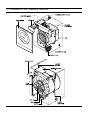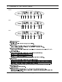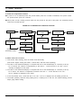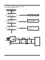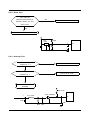
1
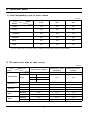
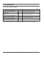
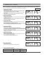
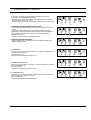
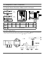
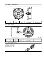
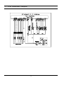
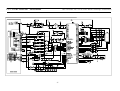
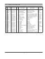
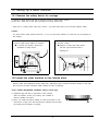
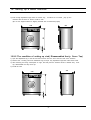
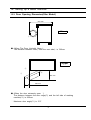
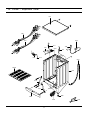
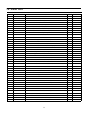
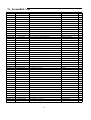
WASHING MACHINE
R1031GWS/YLR
R831GWS/YLR
SERVICE
Manual
CONTENTS
WASHING MACHINE
Caution for the safety during servicing
1. SPECIFICATIONS
2. SAFETY DEVICES
3. OVERVIEW OF THE WASHING MACHINE
4. OVERVIEW OF THE CONTROL PANEL
5. MAIN FUNCTION
6. TECHNICAL POINT
7. GENERAL ERROR FUNCTION
8. TROUBLE DIAGNOSIS
9. TEST MODE
10. DESIGNATION OF MAIN COMPONENTS
11. PCB SCHEMATIC DIAGRAM
11-1. PCB CIRCUIT DIAGRAM
12. SETTING UP A WASH MACHINE
13. ASSEMBLE AND DISASSEMBLE
14. TOOLS FOR DISASSEMBLY AND ASSEMBLY
15. EXPLODED VIEW AND PARTS LIST
Caution for the safety during servicing
1. Do not allow the customer to repair the product.
☞ The person may be injured or the product life may be shortened.
2. Execute A/S after unplugging the power supply unit.
☞ Be care of the electric shock.
3. Do not plug several plugs in the same outlet.
☞ It may cause the fire due to overheat.
4. Check the damage, pressing or burning of the power plug or outlet.
☞ Replace it promptly if it has problem.(may cause the electric shock or fire)
5. Do not clean the main body with the water.
☞ It may cause the electric shock and fire and shorten the product life.
6. The wiring of the harness shall be free from the moisture and tightened during serving.
☞ It shall not be deviated by certain impact.
7. Remove any dust or filth on the housing section,wiring section,connection section during servicing.
☞ Protect the cause of the fire such as the tracking,and etc.
8. Check any mark of the moisture on the electrical parts, harness section and etc.
☞ Replace the parts or remove the moisture.
9. Check the assembly status of the parts after servicing.
☞ Maintain the status before servicing.
10. Pull out the power cord with holding the plug.
☞ Be care of the electric shock and fire when the cord is damaged.
11. Unplug the power plug from the outlet when the wash machine is not used.
☞ Be care of the electric shock and fire due to the strike of the lightening.
12. Do not use or store the spray or flammable materials(including gasoline,alcohol and etc.)
around the wash machine.
☞ Be care of the explosion or fire due to the electric spark.
13. Do not put the bowl of water or wet laundry on the wash machine.
☞ If the water is penetrated to the wash machine, this may cause the electric shock or fire.
14. Do not install the wash machine in the place where the snow or rain falls.
☞ It may cause the electric shock and fire and shorten the product life.
15. Do not push the control buttons with the awl,pin, or sharp materials.
☞ It may the electric shock and trouble.
16. Check the wash machine is leveled horizontally and installed properly on the floor.
☞ The vibration may shorten the product life.
17. Joint the wire by the connector correctly.
☞ When the wire is jointed by the tape, this may cause the fire due to the tracking.
18. When the wash machine is to be laid for the service, put the pad on the floor and lay the product at
side slowly.
☞ If the wash machine is laid front, the relay may be damaged by the tub.
19. When the wash-heater is replaced, check it is inserted in the bracket-heater and screw the nut.
☞ If the wash--is not inserted in the bracket-heater properly, this may cause the noise and
leakage since it is contacted to the drum.
1
1. Specifications
FRONT LOADING TYPE
WASH TYPE
DIMENSION
GROSS
W 661mm X D 576mm X H 850mm
NET
W 598mm X D 450mm X H 844mm
50 kPa ~ 800 kPa
WATER PRESSURE
WEIGHT
GROSS
69 kg
NET
66 kg
5.2 kg (DRY LAUNDRY)
WASH and SPIN CAPACITY
POWER CONSUMPTION
220 V
180 W
240 V
180 W
220 V
1800 W
240 V
2100 W
WASHING
WASHING and
HEATING
MODEL
R1031
R831
R631
500W
430W
380W
SPIN
230V
PUMPING
34 W
49ℓ(STANDARD COURSE)
WATER CONSUMPTION
SPIN REVOLUTION
MODEL
rpm
2
R1031
R831
R631
1000
800
600
2. Safety Devices
※ We adapt 5 safety devices for users to use this wash machine safely.
1) Balancing device (ASSY-Main PCB)
→ When the laundry is out of balance, to prevent the noises and vibrations, the unbalance
detecting sensor helps the laundry laid even and continue the dehydating process.
2) Anti-over water supply device
→ Because water supply value is broken, once water is supplied to the 2/3 level of the door, the
water supplied is drained automatically,
Over -flow error is displayed on the panel
3) Temperature-regulating device(thermistor)
→ To prevent over-heating over the temperature setted up, THERMISTOR senses the temperature of
the machine continuously and helps the wash machine to work at the temperature given by users.
4 Overheating- controlling system
→ Under the circumstances of THERMISTOR inferiority or abnormal condition, if wash-heater is
overheated, automatically, assy -thermal fuse cuts off the power supply to protect the machine to
keep it safe.
5) Delicate clothing safeguard function(ASSY-Main PCB)
→ To protect the clothings which is weak to high temperature, the wash machine senses the
temperature inside the washing tub. if the temperature rises over 50℃ wool washing course and
Delicate washing course display abnormal water temperature on the panel , after draining the
water.
3
3. Overview of the Washing Machine
4
4. Overview of the control panel
R1031
R1031/R1032
①
②
③
④
⑤
⑥
⑦
⑧
R831
R831/R832
①
②
③
④
⑤
⑥
⑦
⑧
R631
R631/R632
①
②
③
④
⑤
⑥
5
⑦
⑧
5. Main function
1) Auto power S/W off function
● After power on, the auto power S/W off function automatically switches power off for you if you do not press
selection button for 10 minutes
● After selecting the function, the auto power S/W off function automatically switches power off for you if you do
not press start/pause button for 10 minutes
● After finishing the last function, the auto power S/W off function automatically switches
power off for you if you do not re-select the course button or manual button
2) Door open function
● If door is open during the operating, all operating is halted, and door error message will be displayed and error
melody will coming out
● Door open error can be cleared by colosing the door. the operating keeps going on
3) No spin function
● If no spin function selected, the operating is finished after last rinse
6
5. Main function
4) Power-out compensation function
● If power is out on selected process, the process before power out is stored to EEPROM, once power is back
the process before power out continues.
● When power is back, washing process starts from the process at the point of the power out, rinse/drain process
starts from the initial process.
POWER-OUT COMPENSATION FUNCTION PROCESS
START
WASHING
RINSE/DRAIN
RINSE/DRAIN
START
PROCESS
POWER OUT
SAVE DATA
POWER OUT
to EEPROM
SAVE DATA
to EEPROM
FINISH
POWER BACK
POWER BACK
MICOM RESTORE
MICOM RESTORE
READ DATA
(PROCESS+TIME)
RESTART
PROCESS
5) Water heater Error function
① This function starts working, when the heater works abnormally.
(this function begins sensing the heater 1 minutes later, after the heater operating)
② The value of the initial thermistor(A1) is compared with that of the thermistor(A2) in 2 minutes (Y=A2-A1)
- For 10 minutes, the variance of temperature(Y) is less than 2℃ "course led 8ea on 40℃/60℃ led on"
message is displayed on the panel.
③ The value of the initial thermistor(A1) is compared with that of the thermistor(A2) in 2 minutes (Y=A2-A1)
- For 2 minute the variance of temperature increases more than 7℃ "course led 8ea on 30℃/60℃
led on" message is displayed on the panel.
④ At this time heater, Error "course led 8ea on 30℃/60℃ led on" is displayed and all working process off
⑤ The heater operating continues during heating hours, if washing hour is left over, the residual washing process
keeps going without heating.
7
5. Main function
6) Fuzzy washing function ( weight-sensing)
☞ After finishing initial water supply,
when the fall of the water level needs supplementary water supply,
Sensing function perceives the weght with the supplementary water supply numbers and starts to work.
Under the course of Cotton, if the supplementary water supply numbers become 3 - 4 times the
function is going at default condition ( high water level ), if 1-2 below that is going at middle level, if 0 below
low water level, heating hours and rinse hours depend on the above data.
Washing hours
Rinse water level
Cotton
High
Default
Default
Middle
Default-12 min
23.30KHZ
Low
Default-25 min
23.70KHZ
※After sensing weight, above hours is decreased from above default hours
7) Bubble -detecting function
At the each condition of washing&dehydrating , rinse&dehydrating , hydrating,
bubble -detecting function works,
this function works 5times normally, if the function detects bubbles at 6 times , the bubble-detecting function
stops and go on to the next process.
● The bubble-detecting function during washing & dehydrating to rinse & dehydrating
after 2 times instant dehydrating and before main dehydrating, if the water level is under 25.45KHZ, Bubble
→ Detecting function thinks there are bubbles and add the bubbles-removing rinse, needing hours are above
hours and 6 min 40 sec.
→ The bubble-detecting function during single hydrating process
after 2 times instant dehydrating and before main dehydrating , if the water level is 25.45KHZ below or
during main dehydrating, water level data is 23.80KHZ below Bubble-detecting function thinks there are
bubbles and add the bubbles-removing rinse 1 times, needing hours are above hours and 5 min 50 sec.
Bubble-detecting function operating process
210rpm
210rpm
20 sec
laundry scattering
draining &reverse
1 min 20sec
unbalance
detecting range
20sec
5sec
15sec
5sec
bubble detection
(default water level 25.45KHZ below)
8
15sec
5. Main function
8) Unbalance detecting & laundry balance positioning system
① Just before the hydrating process and just after reversal rotation for balancing laundry position, this function is
carried out
② The initial 6 sec is the period of reversal rotation for balancing laundry position , Drum rotates 50rpm for
initial 6 sec
③ Next 10 sec, the rotation increases the speed from 50 rpm to 90 rpm slowly
④ During the next 18 sec, drum rotates at the speed of 90 rpm,
the sensor decides the degree of laundry
unbalance with TACHO data which is attached to motor
⑤ If the degree of unbalanced laundry is over 6 times to default value, laundry balancing system carryies out
feed back process 6 times
9
6. Technical point
1) Final dehydrating r.p.m at each course
unit:rpm
Model
R1031
R831
R631
Cotton
1000
800
600
Colour
1000
800
600
Synthetics
800
800
600
Delicates
600
600
600
Wool
600
600
600
Quick
800
800
600
Course
※ You can change the r.p.m to the above a table by use spin button under no spin situation.
2) The water level data at each course
unit:Khz
Water level
Course
Default water level(khz)
23.60
Washing
Cotton/Colour
Rinse
large
23.00
middle
23.30
small
23.70
Supplemetary water
Supplemetary water
START(Khz)
end(khz)
24.20
23.85
24.20
23.90
Washing
23.60
24.20
23.90
Rinse
23.10
24.20
23.90
Washing
23.25
24.00
23.70
Rinse
23.00
24.20
23.90
Washing
23.00
24.00
23.70
Rinse
22.80
23.80
23.50
Washing
23.50
24.00
23.70
Rinse
22.45
24.00
23.50
Synthetics
Delicates
Wool
Quick
10
6. Technical point
3) The other water level data
unit:Khz
The water data unter each conditon
1st water supply (only preparation)
24.60
1st water supply level to washing tub
Overflow error
20.50
The water supplied reach 2/3 of door
25.45
Bubble -detecting water level
Bubble detecting rinse water level
22.60
The water level which can detect bubbles
Water level which can open door
24.10 over
It is possible to open the door
Water level which can drive heater
24.50(3.5ℓ)
Safety water level of wash heater
Water level which can reset the drain
24.50
The water level can be detected after 1st draining
Bubble
detectingatwashing/rinse/dehydrating
※ If water level is 15KHZ below or 30 KHZ above , sensor-pressur is out of order so needs changing.
11
7. General Error Function
When an error occurs, this function starts to keep generating error melody sounds and displays error indicators as
shown in the followings per corresponding error by blinking in 0.5sec interval until the error status is completely cleared out.
In this case, all the driving devices are turned off until the error is cleared out.
1. WATER SUPPLY ERROR
- Display shows such as fig. 1
- Water Supply Error occurs when water level frequency does not show
changes more than 100Hz or water is not supplied
up to the water level presetting for 20 min or more at the time of initial
water supply.
-The error status can be cleared by turning POWER S/W OFF and
resuming the POWER ON initial status.
○ : Light on
● : Light off
fig. 1
2. WATER DRAIN ERROR
- Display shows such as fig.2
- In case the water level frequency is 24.5KHz or less in the initial phase
of UNB-detecting cycle.
- Water Drain error can be cleared by turning POWER S/W OFF and
resuming the POWER ON initial status.
fig. 2
3. OVER-FLOW ERROR
- Display shows such as fig.3
- Over-Flow error occurs when the water level is in abnormal operation.
It can be cleared by turning POWER S/W OFF.
Water is drained prior to POWER S/W OFF and it is forced to be drained
for 2 min if a frequency of more than 24.5 KHz is detected.
fig. 3
4. UNBALANCE ERROR
- Display shows such as fig4.
- Laundry load is unbalanced; loosen any tangled laundry.
- If only one item of clothing needs washing, such as a bathrobe or jeans,
the final spin result might be unsatisfactory and an error message will be
shown in the display panel such as fig 4..
- Unbalance error is cleared by POWER S/W OFF and by resuming the
POWER ON initial status.
5. WATER HEATER ERROR
- Display shows such as fig.5 or fig.6
- In case the water temperature rises by 7∞C or more in 1 min. or by 2∞C
less in 10 min after heating is started.
- It can be cleared by turning POWER S/W OFF.
fig. 4
fig. 5
fig. 6
6 DOOR OPEN ERROR
- Display shows such as fig.7
- Door Open error can be cleared by closing the door.
fig. 7
7. ASSí Y PRESSURE S/W ERROR
* Generated Frequency Signal of WATER LEVEL(W/L) S/W (KHz)
Level
Low Level
High Level
Abnormal W/L Frequency
30.00 KHz
15.00 KHz
12
7. General Error Function
- If the same signal as the above table is detected for more than
5 seconds, it is a PRESSURE S/W Error.
- When the error occurs, water drain pump will operate for 3 min. and
then turn off the water drain pump.
Then the display shows fig. 8 indicating a pressure s/w error indicator.
fig. 8
8. ABNORMAL WATER TEMPERATURE ERROR
- In case the water temperature is 50∞C or more in Delicate and Wool
course.
- At the time of initial water supply, if the water temperature is not
appropriate, water starts to be drained and it is forced to be drained
for 2 min when the abnormal frequency of 24.5KHz is detected.
- Display shows fig. 9
- This error can be cleared by POWER S/W OFF.
fig. 9
9. WATER LEAKAGE ERROR (E9)
- Water Leakage error occures when water is drained naturally after
washing program starts.
fig. 10
10. Tacho Error
- This error occurs in case motor thaco is out of order or tacho siganals
inputted are fewer than 2
- Display shows fig. 11
- This error can be cleared by power s/w off
11. Motor Triac short Error
- This error occurs in case over 300 per 1 sec tacho signals are inputted
power S/w should be off.
-fig. 12 is diplayed.
- This error can be cleared by power s/w off
12. Thermistor error
- This error occurs, when Thermistor circuit is abnormal or the detected
electrical volt is 0.2v below or 4.5v over
- fig. 13 is displayed
- This error can be cleared by power s/w off
13
fig. 11
fig. 12
fig. 13
8. Trouble Diagnosis
- As the micom wash machine is configured of the complicate structure, there might be the service call.
Below information is prepared for exact trouble diagnosis and suitable repair guide.
Caution for the Repair and Replacement
Please follow below instruction for the trouble diagnosis and parts replacement.
1) As some electronic components are damaged by the charged static electricity from the resin part of wash
machine or the human body, prepare the human body earth or remove the potential difference of the
human body and wash machine by contacting the power supply plug when the work contacting to PCB is
executed.
POWER SUPPLY PLUG
2) Since AC220~240V is applied to the triac T1 and T2 on P.C.B, the electric shock may occur by touching
and be careful that the strong and weak electricity are mixed.
3) As the P.C.B assembly is designed for no trouble, do not replace the P.C.B assembly by the wrong
diagnosis and follow the procedure of the trouble diagnosis when the micom is not operated normally.
14
8-1. Trouble Diagnosis
No
Item
Cause and treatment
The power is not supplied
- Is the PCB connector connected well?
- Is the voltage normal?
- Is the power supply plug connected well?
- Is the noise filter connected well?
- Is the secondary output of the power supply transformation normal?
- Is the fuse disconnected? (option)
ï If above points are not found, the PCB assembly is out of order.
Replace it.
The water is not supplied.
- Is the knob open?
- Did you push START/PAUSE button after selecting the course?
- Is the water supply valve connected well?
- Is the winding of the water supply valve continuous?
- Is the connection and operation of the pressure switch normal?
ï If above points are not found, the PCB assembly is out of order.
Replace it.
The wash does not start though
the water supply is stopped.
- Is the connection and operation of the pressure switch normal?
- Is the pressure switch hose damaged so that the air is leaked?
- Is the pressure switch hose bent?
- Check the operation of the water level switch.
ï If above points are not found, the PCB assembly is out of order.
Replace it.
4
The drum does not rotate during
washing.
- Is the belt connected well?
- Is the winding of the motor continuous?
(Rotor winding, stator winding, generator)
- Is the motor protector normal?
ï If above points are not found, the PCB assembly is out of order.
Replace it.
5
The drum rotates by one direction
during washing. (The drum rotates
to one direction for SPIN.)
- The PCB assembly is out of order. Replace it.
(Inversion relay open trouble)
6
Drainage problem.
- Is the drainage hose bent?
- Is the winding of the drainage pump continuous?
- Is the drain filter clogged by the waste?
ï If above points are not found, the PCB assembly is out of order.
Replace it.
7
Dehydration problem.
- The unbalance is detected.
- Put in the laundry uniformly and start again.
Abnormal noise during SPIN.
- Is the pulley nut loosen?
- Is the transport safety device removed?
- Is the product installed on the level and stable place?
(Little noise may be generated during the high-speed SPIN.)
1
2
3
8
9
Leak breaker or current/leak
breaker is down during washing.
<When the leak breaker and current breaker is installed separately>
- When the leak breaker is down, check and make the earth of the outlet.
- When the current is down, the current is leaked.
<Is the breaker down when the leak/current breaker is combined?>
- Check the rated capacity of the current and leak breaker.
The current breaker may be down due to the lack of the current when the
wash machine and other apparatus are used.
In this case, execute the cold water wash to check whether the current capacity is lack.
10
The heating is not executed.
- Is the wash heater terminal unplugged?
- Is the wash heater normal?
- If above points are not found, the PCB assembly is out of order.
Replace it.
15
8-2 . Problem Checkking And Method Of Pcb
8-2-1 The Part Of Power Source
NO Power On
YES
The Voltage Of
NO
Betweenⓐand ⓑIs
Check The Trans
As Big As 12V?
YES
The Voltage Of
Check The Diode(D6,7,8,9,11)
NO
Betweenⓒand ⓓ Is
And Condenser(CE3)
As Big As 12V?
YES
The Voltage Of
Exchange IC2(7805) And
NO
Betweenⓔand ⓓ Is
Check The
As Big As 5V?
Condenser(CE5)
YES
D6,7,8,9
ⓐ
D11
TRANS
IC2
7805
CE5
ⓔ
16
47
2200UF
ⓑ
R14
33K
ⓒ
470UF
R15
33K
17
48
CE3
ⓓ
16
20
8-2-2. Reset Part
The Value Of
Measurement Result Of
NO
Check The Power Source
Between Micom 23 And
Gnd Is 5V?
YES
Check IC3
IC3
7033
R36
23
CE6 1UF
8-2-3. Interrupt Part
Check The Curve
Check D6 - D9
Output Of ⓐ ?
Check The Micom
Check TR13, R46
Number 31 ?
Check The Part Of
Oscillator
R46 4.7K
ⓐ
TR13 KN3904
R17 2.2K
31
C36
C32
R49 C34
17
8-2-4. Checking The Part Of An Oscillator
When The Micom 18,19
Check, The Value Is
NO
Check Resonator
8Mhz?
YES
Exchange Micom And Check R28
R28 1M
XTL1
8MHz
18
18
19
8-2-5. Driving Part Checking
◆ Confirm The Output Of DC5V, When The Every Part Of Micom Number Check,
According To The Some Problem Condition
ex) When The Drain Is Not Operating But Pump Motor Is Operating, Check
The 5Voltage Of Micom
Micom Number, 9 Is
NO
Micom Bad
5Voltage?
YES
The Part Of ⓐ Is
NO
Check The IC 65003
0 Voltage?
YES
Check R38, TRIAC2
MICOM
+12V
IC65003
ⓐ
POWER
R26
ⓐ
DOOR
TRIAC4
R43
ⓐ
COLD
TRIAC5
R47
TRIAC3
R30
TRIAC2
PRE
ⓐ
PUMP
※ Check The Micom 12th In The Above Method When The Cold Water Is Bad
19
1
7
12
2
9
8-2-6. Confirm The Driving Part Of Motor
YES
Motor Is Not Spinning
Check BD1, TRIAC1
NO
Motor Is Not Turnning
YES
Check RELAY3
Right And Left
NO
Check The Tacho Part
12V
MICOM
BD1
CM11
CM2
R5
IC 65003
R45
R11
COIL1
5
TRIAC1
1W 300
3
RELAY3
D12
20
8-2-7. Checking The Tacho Part
Have The Motor Turn In Hand
Is The Rectangular
Check The Surroundings
NO
Curve In The Micom
Circuit And TR11
21,10th ?
YES
Exchange The Motor
+5V
MICOM
R27 4.7K
R23
TR11
21
R22 1K
KN3904
C14
C17
21
C24
9. Test Mode
1
2
3
4
1. Driving Compartment Test Mode
A. Hold down ì 1î and ì 2î keys simultaneously and then press POWER S/W ì 4î on.
B. The driving compartment can be tested when you press ì 3î key right after entering
into the initial stage of the TEST MODE.
ï Driving Compartment Test
COLD VALVE ON(0.3sec) → OFF(0.3sec) → RRE VALVE ON(0.3sec) → OFF(0.3sec) →
Pump MOTOR ON(0.3sec) → OFF(0.3sec) → MOTOR Left (0.5sec) → OFF(0.5 sec) →
MOTOR Right (0.5sec) → OFF(0.3sec) → HEATER RELAY ON(0.3sec) → OFF(0.3sec) → DOOR OPEN
(Function continues when door is closed)
22
10. Designation of Main Components
10-1 Normal / Reverse Revolution of Motor and R. P. M. Control
8
Rotor
9
CW
5
Stator coil
-
ROTOR
10
PROTECTOR
(150 C)
Stator coil
MIDDLE-SPEED
5
1 2 3 4 5 6 7 8 9 10
+
STATOR
9
TACHO
Rotor
HIGH-SPEED
8
+
CCW
STATOR
10
5
H
WASHING MOTOR
<Figure1>
(± 7%)
Resistance
value
<Figure2>
STATOR(51) ROTOR(8.9) TACHO(3.4) PROTECTOR(6.7) "H"(mm)
2.08Ω
1.99Ω
Rated
value
38.8Ω
0
39
Code-No.
Remark
DC31-00002E
R1031
R831
R631
220~240V/50Hz
10-2 Door safety Device
When Door is closed, door stay closed. if "set" is operated,
the door closed, and electronical power flows between
and
23
power supplied to
make it operate.
,
wires have bymetal keep
10-3 Heater
1) Capacity : AC 230V/1900W
2) Location : Bottom of TUB
3) Function : Raise the water temperature
supplied at the wash process.
4) Resistance value : 23~29
5) Thermal Fuse : 169∞C
Thermistor
10-4 Detergent tub and water supply value
A Detergent tub is composed of housing and 3 drawers . supplied water flows into the 3 drawer-detergent tub by
way of classifier at each washing process.
three open drainage way whith detergent and supplied water by way of connector located under the housing flows
into washing tub.
the water supply valve is composed of a hot water valve(1 way) and a cold water valve(3way) and water flow per
min in the valve is below.
Hot water valve(1 way)
10L
water flow(L/min)
resistance value
4.3㏀
power consumption
AC 220v ~ 240V 50/60㎐
usable water pressure
0.5 ~ 8 ㎏/㎤
10-5 Shock absorber and buffer spring
This wash machine is equipped with 2 Shock absorbers with same
capacity and with 2 buffer springs. 2 Shock absorber are placed
under the tub and outside case , 4 buffer springs are placed on the
right and left of the upper side of outside case.
Shock absorber function: during wash, dehydration absorb the shock.
buffer spring: buffering the vibration
device
capacity of Shock absorber
Shock absorber
8±2kg
24
10-6 ASSY-TUB BACK
INNER-BEARING
OUT-BEARING
B
A
C
OIL-SEAL
(unit : mm)
TYPE
INNER-BEARING(A)
OUT-BEARING(B)
OIL-SEAL(C)
Assy-Housing Bearing(D)
Assy-Tub Back
I
ø30
ø25
ø34
DC97-05168A
DC97-00214R
10-7 ASSY- DRUM
A
B
C
(unit : mm)
TYPE
(A)
(B)
(C)
CODE-NO.
REMARK
I
ø30
ø23
ø35
DC97-01463H
Lifter type
R1031/R831/R631
10-8 ASSY-PUMP DRAIN
1) Capacity : AC 230V 34W
2) Location : Front bottom(R)
3) Resistance : 150Ω ~ 180Ω
25
11. PCB Schematic Diagram
26
11-1. PCB CIRCUIT DIAGRAM
This Document can not be used without Samsung's authorization.
27
11-1. ASSY-PCB Part List
NO. Part Code
Code NO
Q'ty
Description
Spercificatio
Remark
1
WB002
1401-001007
1
THYRISTOR-TRIAC
10A,SM10LZ47(TOSHIBA)
TRIAC4
2
WB002
1401-001024
5
THYRISTOR-TRIAC
2A,SM2LZ47(TOSHIBA)
TRIAC2
3
WB003
0402-001023
1
DIODE-BRIDGE
RBV1506,600V,15A,SIP-4
BD1
4
WB004
3501-001180
1
RELAY-MINIATURE
12VDC,RTE24012
RELAY3
5
WB004
3501-001156
2
RELAY-POWER
12VDC,0.53W16000MA,1FORMC
RELAY5
6
WB004
3501-001157
3
RELAY-POWER
12VDC,0.53W16000MA,1FORMC
RELAY1,2
7
WB004
3501-001007
1
RELAY
12Vdc,200mW,5A,(TAKAMISAYA)
RELAY6
8
WB010
DC26-00005B
1
TRANS-FORMER
450MA,220~240VAC,11VDC
TRANS
9
WB003
0402-000137
6
DIODE-RECTIFIER
1N4007,1000V,1A
D15~D19
10 WB006
0504-000130
2
TR-DIGITAL
KSR1105
TR3,TR4
11 WB006
DE13-20016A
1
IC-VOLTREGU
KA7805A
TR7
12 WB006
0504-000159
2
TR-DIGITAL
KSR2105
TR1,TR2
13 WB006
0504-001080
2
TR-DIGITAL
KRC246S
TR3,TR4
14 WB006
0501-000465
1
TR-SMALL
MMBT390X
TR11-13
15 WB007
1202-000141
1
IC-DRIVE
7033,SOT-89
IC4
16 WB008
2802-001058
1
RESONATOR-CERAMIC
8MHz,02%,TP,10×5×8mm
RESO
17 WB007
DE13-20017A
3
IC-DRIVE
KID65003AP,DIP,STICK
IC3,IC5,IC6
18 WB007
1103-001160
1
IC-EEPROM
4C010,128×8BIT,DIP,8P
IC2
19 WB009
DE30-20016A
1
BUZZER
CBE2220BA,STICK
BZ
20 WB010
SW1~7
3404-001022
7
SWITCH-TACT
15V,20mA,130°±40gf,6×6×5mm
21 WB011
DE07-20040A
*
LED LAMP
SLH-34VC70F,RED,T,P15
22 WB012
0703-001056
1
LED DISPLAY
Y-GRN,4dig,7seg,46×19×24.6mm
28
12. Setting up a wash machine.
12-1 Remove the safety device for carriage
1) Remove 3 safety device volts with a enclosed wrench for safety device remove
2) Plug the 3 holes with 3 caps after removing the 3 safety device volts.
* Take care of 3 safety device volts and a wrench , you need these when you move wash machine safely.
Caution
You must remove safety device before use , if not, you have much vibration or much load can br impacted on
the machine.
1. Remove safety device behind of machine
2. Plug the 3 holes
● To protect the machine, remove the
● Plug the 3 holes after safety device
assembled 3 safety device
with the caps enclosed inside of
washing tub
①
②
③
12-2 Install the wash machine on the leveled place.
With the water level adjustment device, adjust the 4 adjustment legs to install the machine leveled on the right,
left, front and rear side. machine's install condition and size is following.
12-2-1 Initial assembled condition (ass'y cover top)
1) Adjustment legs are stick to the bottom of the machine,
when the machine comes out of factory. this condition is
ideal for vibration and noise.
2) When you install the machine initially or move the machine in use,
unscrew the 4 legs to the left and place the machine level and spin
the locking nuts and tighten it strongly.
29
12. Setting up a wash machine.
3) Even though adjustment legs came out all the way,
if machine is not levled , prop up the
machine with the wood or brick to make it even.
(Do not use fragile material or slippery material such as laminated paper)
450
340
17
844
598
12-2-2 The condition of setting up sink( Disassembled Ass'y- Cover Top)
1) Spin the adjustment leg to the left and remove them from the front and rear side of the machine.
2) Remove the 4 locking nuts from adustment legs, and put only adjustment legs back whert those were.
3) After removing the fixing screws(each on right, left side) from the machine whichi is behind ass'y- cover
top, disassemble the assy-cover top.
4) Install the sink.
450
340
17
844
598
30
12. Setting up a wash machine.
12-3. Door Opening Dimension(Slim Model)
840 mm
②
Side
①
● (When The Door Vertically Open )
The distance between door① and the rear side② is 760mm
Upper
②
③
①
225 mm
255 mm
● (When the door extremely open ※)
The distance between the door edge(①) and the left side of washing
machine(②) is 255mm
※ Maximum door angle(③) is 170°
31
13. Assemble and Disassemble
1. ASSí Y-COVER TOP
1) Remove two screws fixing the top-cover on back side.
2) Push the top-cover back about 15mm and pull it up.
3) Ití s possible to exchange and service Assy-Panel
(PCB), the pressure-sensor, the noise-filter,
the water valve and trans(option).
2. FRAME FRONT
1) Remove the top-cover and the assí y drawer.
2) Remove two screws fixing the control-panel on
front side and the screw on right side.
3) Remove the cover-front(L) by using the (-)driver.
4) Pull the lever and open the assí y-door.
5) Part the diaphragm and the wire diaphragm
away from the frame-front.
6) Remove the eight screws fixing the frame-front.
7) Ití s possible to exchange and service the heater,
the pump, the shock-absorber and the door lock
s/w.
32
m
15m
SCREW
13. Assemble and Disassemble
2
3. BELT
1) Remove the top-cover.
2) Disassemble and assemble the belt.
3) Check the belt is located at center of the motor-pulley.
<When assemble the belt>
Hook the belt on the motor pulley 1) and place it
around the pulley 2).
PULLEY
BELT
1
MOTOR
4. MOTOR
1) Lay down the washer on left side.
2) Remove the wire housing from the motor.
3) Remove the bolt fixing the motor with the box
drive on back side.
4) Remove the motor.
Motor Assemble Hole
33
14. Tools for Disassembly and Assembly
NO.
TOOL
¿
Box driver
¡
Double-ended
spanner
¬
Heater (1)
Motor (1), Balance (5)
1 Pulley hole
10, 13,19mm
Replaceable for the box driver.
Vice pliers
Tool to protect the idle and abrasion of the bolt for the box driver.
Other(Driver, Nipper, Long nose) General tools for the after service.
ƒ
JIG for the Tub
1 (Disassemble and Assemble)
¿
√
¬
10
19
13
8
12
√
10
mm
¡
13
mm
19
mm
ƒ
17
√
10mm
13mm
19mm
34
15. TOP(FRONT) - Exploded View
J014
C008
P003
C010
Y001
J006
C021
G007
V002
V010
C036
P002
V001
V009
V003
F004
V016
V024
35
15. TUB - Exploded View
R025
R008
R014
R020
T031
R015
R018
R007
R016
R026
R003
V007
R013
R021
R005
R024
R028
R010
R023
R006
36
15. CASE - Exploded View
J001
C007
G008
T024
J012
J010
C023
C009
J008
J012
R017
G003
G018
P001
R012
R012
B006
G020
G009
37
G025
15. Parts List
NO.
CODE NO.
DESCRIPTION;SPECIFICATION
Q'TY
B006
DC97-02079D
ASSY-LEG;SBP2,SD455,SD405,FLANG TYPE/25M
4
C007
DC96-00625A
ASSY-M.WIRE HARNESS;SD405,ROLD-DOOR
1
C008
DC64-00647A
PANEL-CONTROL;SBP-2,HIPS,-,-,-,-,WHT,40c
1
C009
DC62-00024F
VALVE-WATER;B1215J,NYLON66/250TRMN,-,-,N
1
C010
DC61-10316B
CAP-RINSE;SEW-740DR,PP(TB-52),-,-,-,WHT,
1
C013
DC63-00455A
COVER-TOP;SD455-PJT,ABS,-,-,-,-,-,SNOW/W
1
C021
DC64-00739A
INLAY-PANEL;R1031GWS/YLR,PC,T0.5,-,-,SIL
1
R1031
C021
DC64-00739B
INLAY-PANEL;R831GWS/YLG,PC,T=0.5,-,-,SIL,ICON/SEBO/SEKO
1
R831
C023
DC32-30006P
SENSOR PRESSURE;DN-S14(P1291),TERMINAL-T
1
C036
DC63-00450A
COVER-FRONT;S821,PP,T1.8,-,-,-,-,WHT,ROL
1
F004
DC64-00646A
HANDLE-DOOR;SD455-PJT,POM,-,-,-,-,WHT,RO
1
G003
DC97-00139K
ASSY-HOSE DRAIN(O);SLIM/L1735MM,PP(BP110
1
G007
DC97-04628V
ASSY-PANEL FRONT;R1031GWS/YLR,SBP/WHT/SI
1
R1031
G007
DC97-04628W
ASSY-PANEL FRONT;R831GWS/YLR,SBP/WHT/SILVER-INLAY
1
R831
G008
DC96-00146A
ASSY-POWER CORD;P1291~P6091,250V/16A(PV)
1
G009
DC96-00149A
ASSY-PUMP DRAIN;P8091/P6091,220~240V/50H
1
G018
DC64-00693A
SHUTTER;SD455,PP,4,-,-,WHT,45CM SLIM
1
G020
DC61-10672A
COVER-FRONT(L);SWF-P12,PP(BJ-730),-,-,-,
1
G025
DC62-10289B
HOSE-WATER(C);WIP4013SRW,PVC+NYLON,ID10.
1
J006
DC61-00366A
BODY-DRAWER;SL-600,TB-53,-,-,-,-,-,-
1
J008
DC29-00006A
FILTER-EMI;DFC-2712R,P/PV/SLIM,250V,12A,
J010
DC67-00051B
HOSE-DRAWER;Q1636GW/XEU,EPDM,ID9.5,OD13.
J012
DC61-00708A
SPRING-HANGER;F-PJT,HSWR,CD2.8,-,-,L170,
2
J012
DC61-00708B
SPRING-HANGER;F-PJT,HSWR,CD2.8,-,-,L181,
2
J014
DC97-04748L
ASSY-HOUSING DRAWER;SD455,5.2KG/COLD/2-W
1
1
0.42
J014
DC97-02132C
ASSY-HOUSING DRAWER;S1093~S6093/2-WAY,SL
1
P001
DC99-00415A
ASSY-PAINT;SD455/WHT,COLD
1
P002
DC97-00702A
ASSY-FRAME FRONT;P6091,ROUND-TYPE
1
P003
DC97-00417A
ASSY-FRAME PLATE(U);SWF-P12,FRAME-PLATE(
1
R003
DC91-12077A
ASSY-CLAMP DIAPHGRAM;SWF-P12,TUB
1
R005
DC97-01463H
ASSY-DRUM;SD405/SD455/LEFTER,5.2KG/NEW-D
1
R006
DC47-00006B
HEATER;KAWAI,P-SLIM MODEL,SUS316L,-,-,23
1
R007
DC97-00214R
ASSY-TUB BACK;SD405/SD455,5.2KG/1200rpm
1
R008
6602-001072
BELT-TIMING GEAR;POLYURETHAN,L1270,J5,ME
1
R010
DC61-00856A
BRACKET-HEATER;SB-PJT,STS430,-,-,-,-,-
1
R012
DC66-00320A
DAMPER-SHOCK;SB-PJT,ABS,-,-,-,-,WHT,AKS-
2
R013
DC61-20219E
DOOR-DIAPHRAGM;SEW-HW107,EPDM,-,-,-,-,GR
1
R014
DC62-10303A
HOSE-AIR;-,EPDM,ID24,-,-,L130,BLK,SWF-P1
1
R015
DC62-10305A
HOSE-DRAWER TUB;-,EPDM,ID35,-,-,L158,BLK
1
R016
DC62-00121A
HOSE-FILTER TUB;S1005J,EPDM,ID65,-,-,-,-
1
R017
DC67-00107A
HOSE-PRESSURE;S821,PE-BLOW,ID13.2,OD6.2,
1
38
REMARK
15. Parts List
NO.
CODE NO.
R018
DC31-00002E
MOTOR-DRUM;HXGN2I.02,SFW-P8,-,50Hz,-,-,L
DESCRIPTION;SPECIFICATION
1
R020
DC66-10176F
PULLEY;SD405/SD455,ALDC,-,-,-,D297,-,DRU
1
R021
DC62-00160A
SEAL-OIL;TS0-PJT,NBR(SD35),BLK,-,-,-,JIN
1
R023
DC61-00365B
TUB-FRONT;SL-600,FRPP(GR15%)SAMBAK,-,-,-
1
R024
DC62-20311A
VANE-CHECK;SWF-P12,EPDM,-,-,BLK,-,
1
R025
DC67-00042B
WEIGHT-BALANCER;F1215,GC-150(CHINA),-,-,
1
R026
DC67-00050B
WEIGHT-BALANCER;F-1215,GC-150,-,-,-,-,F-
1
R028
DC62-40183A
PACKING-TUB;SWF-P12,EPDM,-,-,-,-,-,BLK,-
1
T024
DC96-00626A
ASSY-WIRE HARNESS;SD405,SUB(HIGH)
1
T031
DC61-00041A
CUSHION-MOTOR;SWF-6V,BUTYL,-,-,-,ID16/OD
1
V001
DC63-00353A
COVER-DOOR;SB-PJT,ABS,-,-,-,-,-,-,ROUND
1
V002
DC97-00100C
ASSY-HINGE;S1005J,OPEN ANGLE 180DEG
1
V003
DC97-04750A
ASSY-HOLDER GLASS;SB-PJT,HOLDER+HINGE
1
V007
DC91-12078A
ASSY-WIRE DIAPHRAGM;SWF-P12,FRAME-FRONT
1
V009
DC61-00013A
DOOR-GLASS;GLASS,NTR,SWF-P12
1
V010
DC64-00653A
DOOR-LOCK S/W;DA,PA6-G,-,H82,W50,-,BLK,2
1
V016
DC66-00355A
LEVER-DOOR;SD455-PJT,POM,-,-,-,-,WHT,EMZ
1
V024
DC61-01065A
SPRING-HANDLE;SEW-HR805,STS304,CD1.0,-,O
1
Y001
MFS-R1031-00
ASSY PCB PARTS;MF-R1031-00
1
R1031
Y001
MFS-R831-00
ASSY PCB PARTS;MF-R831-00
1
R831
39
Q'TY
REMARK
15. Screw/Bolt List
CODE NO.
DESCRIPTION
DC97-02412A
ASSY-BOLT
SWF-P12,MOTOR, M8*L62
MOTOR
1
DC97-02412A
ASSY-BOLT
SWF-P12,MOTOR, M8*L62
WEIGHT BALANCE(R)
1
DC97-02412A
ASSY-BOLT
SWF-P12,MOTOR, M8*L62
WEIGHT-BALANCER(L)
1
DC97-06080A
ASSY-BOLT
SEW-3HR107,BOLT+WASHER
PULLEY+SHAFT
1
6011-001421
BOLT-FLANGE
M7,L61(29.4),ZPC(YEL),SWRCH18A
WEIGHT(L)
1
6011-001492
BOLT-FLANGE
M8,L25,PASS,STS304,NYLOCK,P1.25
-
3
6011-001421
BOLT-FLANGE
M7,L61(29.4),ZPC(YEL),SWRCH18A
-
1
6011-001447
BOLT-HEX
M8,L123(25),ZPC(YEL),SWRCH18A,WP,NYLOCK
WEIGHT(U)
1
6011-001448
BOLT-HEX
M8,L170(25),ZPC(YEL),SWRCH18A,WP,NYLOCK
WEIGHT(U)
1
6011-001499
BOLT-HEX
M8,L104.5(50),ZPC(YEL),SWCH10AK,2BODY,DAMPER
TUB+DAMPER
2
DC60-40005A
BOLT-HEX
M4,L60,ZPC2(YEL),SS41C,-,-,-,-
DC60-40144A
BOLT-HEX
M10,L41,ZPC2(YEL),SM10C/DAMPER
DAMPER+FRAME
2
DC61-00201A
BRACKET-NUT
SBHG-R,P1291,T3,-,-,-,NO-PAINT/MOTOR
MOTOR
1
DC61-40348B
BRACKET-NUT
SBHG-R,P1291,T3,-,-,-,NO-PAINT
-
2
DC61-00201A
BRACKET-NUT
SBHG-R,P1291,T3,-,-,-,NO-PAINT/MOTOR
-
1
DC61-40348B
BRACKET-NUT
SBHG-R,P1291,T3,-,-,-,NO-PAINT
-
2
DC60-50010A
NUT-DIAPHRAGM
EGI,M4,-,-,2.5TX20X8
-
1
DC60-50010B
NUT-DIAPHRAGM
EGI,M4.2,-,-,2.5TX20X8
-
1
DD60-50018A
NUT-FLANGE
SPECIFICATION
-,M5XP0.8,FZY,MSWR10,-
Design LOC
-
Q'TY
1
HINGE
2
6006-001170
SCREW-ASSY TAPP WS,TH,+,M4,L10,ZPC(YEL)
B/K-PRESSURE+FRAME
1
6006-001170
SCREW-ASSY TAPP WS,TH,+,M4,L10,ZPC(YEL)
P/CORD(E/W)
1
6006-001170
SCREW-ASSY TAPP WS,TH,+,M4,L10,ZPC(YEL)
E/W(SUB)+FRAME(F)
1
6006-001172
SCREW-ASSY TAPP WE,TH,+,M4,L12,ZPC(YEL)
FRAME-FRAME FRONT
7
6006-001172
SCREW-ASSY TAPP WE,TH,+,M4,L12,ZPC(YEL)
FRAME-PLATE-UPPER
4
6001-001773
SCREW-MACHINE
TH,+,M5,L12,
HINGE+FRAME
2
6001-001773
SCREW-MACHINE
TH,+,M5,L12,
HINGE+HOLDER
2
6009-001342
SCREW-SPECIAL
TH,+,,M5,L11,ZPC(YEL)
FRAME(TOP)
2
6009-001343
SCREW-SPECIAL
PH,TORX,,M4,L10,PASS
P/CORD
1
6002-000471
SCREW-TAPPING
TH,+,1,M4,L12,PASS,STS304,-
COVER-DOOR
4
6002-001310
SCREW-TAPPING
TH,+,2S,M3.5,L20,PASS
S/W-DOOR+FRAME
2
6002-000445
SCREW-TAPPING
TH,+,2S,M4,L18,NTR,STS304
PANEL+FRM+HOUSING-D
3
6002-001327
SCREW-TAPPING
PWH,+,1,M4,L12,NI PLT
C/TOP+FRAME
2
6002-000630
SCREW-TAPPING
PH,+,2S,M3,L8,ZPC(YEL),SWRCH18
B/K+PRE-S/W
2
6002-000213
SCREW-TAPPING
TH,+,1,M4,L12,ZPC(YEL),SWRCH18
TUB-FRONT+PRESSURE
1
6002-000444
SCREW-TAPPING
TH,+,2S,M4,L14,NTR,STS304
B/K-HEATER
2
6002-000471
SCREW-TAPPING
TH,+,1,M4,L12,PASS,STS304,-
VANE-CHECK
1
6002-000213
SCREW-TAPPING
TH,+,1,M4,L12,ZPC(YEL),SWRCH18
C-PANEL+PCB
3
6002-000525
SCREW-TAPPING
FH,+,1,M4,L12,PASS,STS304
C-PANEL+FRAME
1
6002-001006
SCREW-TAPPING
TH,+,2S,M4,L12,-,STS410
PUMP+FRAME
2
6002-000630
SCREW-TAPPING
PH,+,2S,M3,L8,ZPC(YEL),SWRCH18
6003-000226
SCREW-TAPTITE
TH,+,S,M4,L8,ZPC(YEL),SWRCH18A
W/V+FRAME
2
6003-000226
SCREW-TAPTITE
TH,+,S,M4,L8,ZPC(YEL),SWRCH18A
EARTH
1
DC60-60040A
WASHER-NYLON
-,ID10.5,OD32,T2,-,PBSP-1/2H
FIXER
1
DC60-60044A
WASHER-PLAIN
-,ID10.5,OD30,T3,-,STS304
DAMPER+TUB
2
DC60-60044B
WASHER-PLAIN
SBC,ID8.4,OD30,T3,-,-,-
FIXER
1
40
-
2
ELECTRONICS
This Service Manual is a property of Samsung Electronics Co.,Ltd. ©Samsung Electronics Co., Ltd. August 2003
Any unauthorized use of Manual can be punished under applicable Printed in Korea
International and/or domestic law.
Code No. : DC68-01956A