1
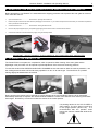
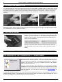
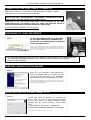
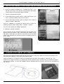
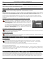
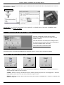
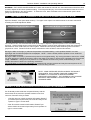
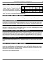
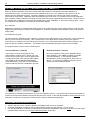
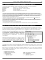
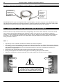
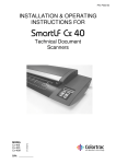
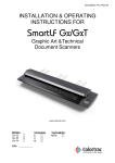
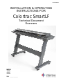
P/N:P002038
INSTALLATION & OPERATING
INSTRUCTIONS FOR
Colortrac SmartLF
Technical Document
Scanners
MODEL
4080E
4080C
4080M
S/N: ___________
2
Colortrac SmartLF Installation and Operating Manual
1. SAFETY PRECAUTIONS
To prevent fire or shock hazard do not expose the scanner to rain or moisture.
Do not cover the scanner with paper or drawings which might obstruct the unit’s vents for long periods while the unit is
being operated as this may lead to overheating and constitute a possible fire hazard.
Do not modify the desk mounted scanner by removing the rubber feet as this may impair the air circulation around the
unit and lead to overheating.
Avoid leaning heavily on the scanner when it is mounted on the stand as the unit could be damaged or become
unstable and result in personal injury.
This symbol is intended to alert the user to the presence of uninsulated
“dangerous voltage” within the product’s enclosure that may be of sufficient
magnitude to constitute a risk of electric shock to persons.
This symbol is intended to alert the user to the presence of important
operating and maintenance instructions in the literature accompanying the
product.
This symbol is intended to alert the user to the presence of important
operating and maintenance instructions. The equipment being used
constitutes a potential finger trap and could cause personal injury.
SAFETY INSTRUCTIONS
DO NOT expose the scanner to extreme temperature conditions
(below 15ºC or above 30ºC)
DO NOT expose the scanner to extreme humidity conditions (less
than 15% or more than 85% Relative Humidity).
DO NOT expose the scanner to direct sunlight, rain or storm.
PAS144
P/N: P002038 Colortrac Ltd © 2004
Colortrac SmartLF Installation and Operating Manual
3
2. CONTENTS
1.
2.
3.
4.
5.
6.
7.
8.
9.
10.
11.
12.
13.
14.
15.
16.
17.
18.
19.
20.
21.
22.
Safety precautions........................................................................................................................................... 2
Safety instructions ........................................................................................................................................... 2
Contents ......................................................................................................................................................... 3
Unpacking SmartLF from its box...................................................................................................................... 4
Parts List......................................................................................................................................................... 4
Lifting the Scanner from its carton ................................................................................................................... 4
Removing the shipping protection and setting up SmartLF............................................................................... 5
Opening the SmartLF lid.................................................................................................................................. 5
Closing the SmartLF Lid .................................................................................................................................. 6
Getting started ................................................................................................................................................ 6
The Windows XP .NET FRAMEWORK V1.1 environment................................................................................ 6
Connecting the USB2 cable to SmartLF .......................................................................................................... 7
Preparing to load the driver ............................................................................................................................. 7
Windows asking for the driver.......................................................................................................................... 7
Inserting the Colortrac SmartLF CD................................................................................................................. 7
Checking for the SmartLF driver ...................................................................................................................... 8
Installing SmartLF s/w from the software installation CD .................................................................................. 9
Loading a document into SmartLF................................................................................................................... 9
SmartLF document handling.......................................................................................................................... 10
. . During the loading process ........................................................................................................................ 10
. . While SmartLF is under program control.................................................................................................... 10
Windows XP and WIA scanner panel control ................................................................................................. 10
Your first scan with SmartLF.......................................................................................................................... 11
SmartLF SCAN-TO- functions ...................................................................................................................... 11
SmartLF has three COLOUR modes ............................................................................................................. 12
Opening and closing the cover ...................................................................................................................... 12
The SmartLF Variable Paper Hold Down (VPHD) system .............................................................................. 13
SmartLF has intelligent file overwrite/ renaming............................................................................................. 13
SmartLF document sizes............................................................................................................................... 14
The SmartLF Preview window ....................................................................................................................... 14
Cropping in SmartLF ..................................................................................................................................... 14
Copying from SmartLF .................................................................................................................................. 14
Document sizes marked on the scanner ........................................................................................................ 15
transparent and opaque originals................................................................................................................... 15
Double-sided originals ................................................................................................................................... 15
Thickness of media compatible with SmartLF ................................................................................................ 15
Stiffness of media compatible with SmartLF .................................................................................................. 15
Scanner maintenance ................................................................................................................................... 15
Glass contamination and scratching .............................................................................................................. 15
Automatic & Manual calibration of SmartLF ................................................................................................... 16
Field upgrade of SmartLF to a higher model .................................................................................................. 17
Warranty information ..................................................................................................................................... 18
Main Features of SmartLF............................................................................................................................. 18
Appendix 1. – Computer requirements for SmartLF ....................................................................................... 19
How to check that the computer has a USB2 interface................................................................................... 19
The USB2 Interface / Computer connection................................................................................................... 20
Appendix 2. - Using the thick media adjustment............................................................................................ 20
Appendix 3 - Windows .NET Framework environment ................................................................................... 21
SmartLF model 4080 Technical Specification ................................................................................................ 22
DECLARATION OF CONFORMITY .............................................................................................................. 23
(The serial number of this unit will be required when seeking support or maintenance for SmartLF. Record it on the
front page of the manual for easy reference).
PAS144
P/N: P002038 Colortrac Ltd © 2004
4
Colortrac SmartLF Installation and Operating Manual
3. UNPACKING SMARTLF FROM ITS BOX
SmartLF ships in a single double-skinned box (35kgs). It is advisable to prepare a strong desk surface or similar area
capable of taking the weight of the scanner (26.5kg). You will need an assistant to lift the scanner from its carton.
PARTS LIST
Quick start guide A3 sheet .................................................................1
Power cable (specified for country) ....................................................1
USB2 scanner data cable (2m) ..........................................................1
Software installation CD (includes this manual in pdf format)..............1
Document Support Tray ....................................................................3
LIFTING THE SCANNER FROM ITS CARTON
1. Make sure the scanner box is resting on the floor the correct way up (look at the name on the side).
2. With the help of an assistant remove the lid from the larger box and then take out the three foam spacers that
protect the inner box. The inner box contains the scanner.
3. Remove the lid from the smaller box and pull back the plastic wrapping to expose the top of the scanner.
WARNING: DO NOT TRY TO REMOVE THE SCANNER WHILE STILL INSIDE ITS PLASTIC WRAPPING AS
THIS WILL MAKE IT MORE DANGEROUS TO HANDLE.
4. With two people, lift an end of the scanner each and begin to remove it from its packing carton. Observing correct
lifting technique (i.e. bend knees and straight back) lift the scanner and position it carefully onto the working area
or the optional floor stand. The choice of position for SmartLF should allow proper air circulation around the device
in accordance with normal office equipment practice.
5. The electricity supply should be taken from a switched output and be located within easy reach of the scanner
operator.
6. The computer used with SmartLF should be located so as not to strain the USB cable or present a cable tripping
hazard to the operator or others.
PAS144
P/N: P002038 Colortrac Ltd © 2004
Colortrac SmartLF Installation and Operating Manual
5
4. REMOVING THE SHIPPING PROTECTION AND SETTING UP SMARTLF
Before attempting to use SmartLF it is essential that the shipping protection which protects the scan glass is removed
from inside the scanner:
•
Open the SmartLF lid ......................see section 5. Opening the SmartLF lid
•
Remove the piece of foam and retain with the packaging for the scanner. If you need to transport the scanner later you will need to replace this
item to protect the scanner optics.
•
Close the SmartLF lid .....................see section 6. Closing the SmartLF lid
•
Fit the three paper support trays by compressing (springing) them into the slots on the back of the scanner
•
Connect the scanner to the local electricity supply using the cable provided
IMPORTANT – DO NOT CONNECT THE SCANNER TO THE COMPUTER UNTIL INSTRUCTED
5. OPENING THE SMARTLF LID
The SmartLF lid is in two parts, the complete lid, which is opened to allow cleaning of the scan glass and the
lightweight cover part which can be opened to permit adjustment of the document scanning pressure.
To raise the whole lid first PRESS IN AND PUSH UPWARDS the two side catches. With the catches pressed in, use
the forefingers and thumbs to lift the lid slowly upwards in an arc on its rear hinges. The lid will lock in a position
leaning slightly backwards from the vertical.
During opening the catches can be ‘latched’ to prevent damage to the end mouldings when the lid is closed later.
Alternatively remember to squeeze the catches inwards towards the centre of the scanner when lowering the lid back
down again. DO NOT try to lower the lid with the catches in the locked position.
Lid showing latches in the LID CLOSED or
OUT position. The lid is heavy but will lock
in the upright position (about 110º). It is
recommended that the operator avoid
leaving the scanner unattended while the lid
is open.
PAS144
P/N: P002038 Colortrac Ltd © 2004
6
Colortrac SmartLF Installation and Operating Manual
6. CLOSING THE SMARTLF LID
To close the SmartLF lid, first check that the latches are in the LID OPEN or retracted position and then lower it slowly
to the horizontal position. Engage the latches at the lowest lid position by pushing gently on the lid while at the same
time pushing down and outwards on the catch levers to release them into the lock position. Allow the lid to spring
upward until the mechanism locks into position. Repeat on the opposite side. The lid is now closed and ready for
scanning.
STEP 1
STEP 2
STEP 3
Attempting to lift the lid of the scanner without using the side catches may open the top cover that provides access to
the variable paper hold down adjustment sliders.
7. GETTING STARTED
SmartLF can now be switched on. The liquid crystal text display (LCD)
will light up and after a few seconds will display the model number and
firmware level of SmartLF. After loading a document the display will
change to the word READY.
Start up the Windows 2000 or Windows XP Professional / XP Home
computer that will be used with SmartLF. Wait for Windows to finish
loading.
FOR MORE DETAIL ON MINIMUM SPECIFICATIONS FOR BEST SMARTLF PERFORMANCE SEE APPENDIX 1.
THE WINDOWS XP .NET FRAMEWORK V1.1 ENVIRONMENT
SmartLF software requires the Windows.NET V1.1 Framework environment to
be installed on the scanner computer. It is recommended to install .NET even
if you purchased the ScanWorks or CopySmart software options. SmartLF is
simple to use and can be run on any computer connected to the SmartLF
scanner without a license key.
We have included Windows .NET Framework V1.1 on the SmartLF Software
Installation CD which ships with this scanner but recommend that you check
the Internet in case a more recent version has been released by the time you
read this document. Go to the Windows update pages at www.microsoft.com for
more information.
In time .NET will become part of XP via the Service Pack upgrade and it will not be necessary to add it to the
installed operating system. See Appendix 3 in this document for more information on .NET Framework and how to
check if it is installed on the computer you intend to use for SmartLF.
PAS144
P/N: P002038 Colortrac Ltd © 2004
Colortrac SmartLF Installation and Operating Manual
7
CONNECTING THE USB2 CABLE TO SMARTLF
With SmartLF switched on, locate the included USB2 cable and plug the smaller
square end into the back of the scanner (see picture).
SMARTLF MUST BE USED WITH A USB2 COMPUTER INTERFACE. ATTEMPTING TO
USE SLOWER USB1.1 INTERFACES WILL CAUSE SMARTLF TO SCAN VERY SLOWLY
AND POSSIBLE CALIBRATION MALFUNCTION MAY RESULT
IMPORTANT: IF YOU ARE USING OTHER USB1.1 KEYS (DONGLES) ON THE SAME
COMPUTER ENSURE THAT SMARTLF DOES NOT SHARE THE SAME USB CIRCUITRY
INSIDE THE COMPUTER OR SCANNING SPEEDS WILL BE REDUCED.
DO NOT CONNECT SMARTLF TO THE PC YET!
PREPARING TO LOAD THE DRIVER
STEP 1
PLUG THE REMAINING END (FLAT SECTION)
OF THE USB2 CABLE INTO A SPARE USB2
INTERFACE - THE DRIVER INSTALLATION WILL
START AUTOMATICALLY.
NOTE: At this point Windows XP will detect the new hardware and display the
following message in the System Tray area (normally the lower right-hand side of
the screen). Please note that the scanner at this point may be referred to as P20
Scanner – this is completely normal.
AT THIS POINT WINDOWS SHOULD DETECT SMARTLF AND AUTOMATICALLY BEGIN RUNNING
THE WINDOWS HARDWARE WIZARD. HAVE THE COLORTRAC SMARTLF SOFTWARE
INSTALLATION CD READY.
WINDOWS ASKING FOR THE DRIVER
STEP 2
WAIT for a few moments to allow Windows to
start the Hardware Wizard. The wizard will take
you through the next steps of the installation.
The wizard will respond by displaying this screen.
NOTE: If the CD is not detected in the next step you will need to tell the Wizard to
search for the drivers automatically by clicking the first button or direct the search
manually by clicking the second button.
INSERTING THE COLORTRAC SMARTLF CD
STEP 3
At this point insert the SmartLF CD containing the
driver. After one or two seconds Windows will detect
the CD and replace the wizard Welcome screen
(STEP2) with the ‘wizard searching’ screen shown
here.
IF THE SMARTLF CD STARTS - PRESS EXIT.
ALLOW THE HARDWARE WIZARD TO CONTINUE
NOTE: SmartLF may be referred to as ‘P20’. This is normal.
PAS144
P/N: P002038 Colortrac Ltd © 2004
8
Colortrac SmartLF Installation and Operating Manual
STEP 4
Windows will search through the CD contents
until it locates the driver and then transfer it to the
computer file system. You should see a screen
similar to this.
STEP 5
During copying Windows will interrupt the
process with a ‘Continue Anyway / STOP
installation - Windows Logo testing failure’
message.
This is completely normal.
Click the button labelled ‘Continue Anyway’
STEP 6
The Hardware Wizard will finish by
showing this screen. Click the Finish
button to complete the installation of the
SmartLF driver.
The SmartLF USB driver is now transferred. Whenever the scanner is plugged into the computer, Windows will
identify the USB (Universal Serial Bus) device as SmartLF and automatically load this driver. The scanner can be
plugged and disconnected freely like any regular USB device without needing to re-boot the computer.
CHECKING FOR THE SMARTLF DRIVER
The Windows system will allow the operator to check for
correct installation of the driver. Should the driver ever
be accidentally removed or require updating or in the
unlikely event of the user experiencing problems with
SmartLF this check can be useful.
Using the Windows Control Panel click on the System
Properties icon. From here click the Hardware tab and
look for the Imaging devices entry.
Right clicking on the SmartLF Scanner entry will bring up
the Properties for the device where the status of the
scanner is displayed. The status should be ‘ This device
is working properly’
NOTE: When SmartLF is not connected or not poweredup there will be no SmartLF Scanner entry visible under
the Imaging devices heading in the hardware listing of
the computer.
PAS144
P/N: P002038 Colortrac Ltd © 2004
Colortrac SmartLF Installation and Operating Manual
9
8. INSTALLING SMARTLF S/W FROM THE SOFTWARE INSTALLATION CD
1. Insert the software installation CD. It should Auto-Play. If the
CD fails to launch go to the CD drive using Explorer and doubleclick the launch file to start the installer manually.
2. Click the ‘Install Products’ button.
3. At the install products screen click the ‘.NET install’ button if you
have not already installed .NET from the Internet.
4. At the install products screen click the ‘SmartLF Scan’ button to
install the SmartLF application.
Once the installation is complete you will be able to locate the
SmartLF program under Program Files > Colortrac > SmartLF.
You have now installed the SmartLF application.
5. Testing the software installation
Go to Programs from the Windows Start button and navigate to the
SmartLF entry and release. After a small delay the SmartLF screen
will display. Note that if the scanner is not powered up or the USB2
cable is not connected the software interface will appear greyed as
shown below.
9. LOADING A DOCUMENT INTO SMARTLF
Documents are loaded right-side justified and face-down with the edge of the paper in line with the first mark of the
document ruler markings. Look for the yellow paper symbol.
Colortrac SmartLF is not limited to scanning recognised document sizes, for example A1, A2 and E size. The
maximum scan width for SmartLF is 1016mm (40”) but the maximum length is limited only by the attached computer
and scanning software. As soon as the READY status is displayed (after 10 seconds), documents can be loaded into
the scanner.
PAS144
P/N: P002038 Colortrac Ltd © 2004
10
10.
Colortrac SmartLF Installation and Operating Manual
SMARTLF DOCUMENT HANDLING
There are two areas where a clearer knowledge of the SmartLF system is important. Refer to Sections 12 & 13 for
details on setting the Variable Paper Hold Down (VPHD).
. . DURING THE LOADING PROCESS
AUTO
SmartLF document loading is fully automatic – no buttons need to be pressed.
With two hands, place the document on the scanner with the longest edge (if possible) towards the scanner opening.
The document is now pushed against the stationary rollers, ‘squared up’ and held in this position. The display will
change to ‘LOAD’ as SmartLF detects the media. After one second SmartLF will start to load the document.
Once a document is loaded, SmartLF software icons or the scanner panel itself can be used to start the scanning
process. The panel display will show the word ‘Scanning’ just before and during movement of the document through
the scanner.
REMOVING A LOADED DOCUMENT/ CORRECTING A SKEWED DOCUMENT
Pressing the red button on the SmartLF panel less than two seconds after
loading will ABORT THE LOAD and rewind the document. This is useful
when a document skews slightly, loads awkwardly or needs to be rotated to a
better or longer side.
If the display has returned to READY the document must be advanced to the
rear of the scanner or physically removed by releasing the SmartLF lid using
the catches. (The paper transport has been optimised and no rewind from
the panel or software is possible).
ADVANCING (FORWARD FEEDING) THE DOCUMENT
After a document is loaded pressing this button will advance the document. SmartLF will move the document
for as long as the button is held down.
EJECTING THE DOCUMENT
After a scan has completed and where the software is instructed to hold the document, pressing this button will
eject the document from the rear of the scanner.
. . WHILE SMARTLF IS UNDER PROGRAM CONTROL
STOPPING SmartLF
During scanning, pressing this button will abort the scan process and eject the document. The SmartLF
software will remain running (hourglass icon) ready for the next document to be loaded. To stop SmartLF
software processing the batch press the function button again.
(For ScanWorks users when ‘Do nothing’ is set, the document will stop. When Eject is set the document will be ejected).
SmartLF software operates as follows:
Once started and a function is selected, SmartLF will continue scanning to file, copying to printer or emailing as each
new document is fed into the scanner. Pressing the running function button again (hourglass showing) will cancel any
operation and return the system to standby.
WINDOWS XP AND WIA SCANNER PANEL CONTROL
The XP Windows Image Acquisition Device Driver Interface (WIADDI) supports custom scanner interfaces allowing
SmartLF hardware to start key program operations. The SmartLF user control panel has three blue buttons marked
COPY, FILE and EMAIL. When set up in Windows XP these buttons allow the operator to control the operation of the
SmartLF software from the scanner itself. They will only operate with the standard SmartLF software and only with
PAS144
P/N: P002038 Colortrac Ltd © 2004
Colortrac SmartLF Installation and Operating Manual
11
Windows XP. To set up the panel buttons go to the Windows XP Control Panel and set the properties for ‘Scanners
and Cameras’ as below.
CONTROL PANEL
IMPORTANT: TO ACTIVATE THE SMARTLF S/W REMOTELY PLEASE PRESS THE BLUE SCANNER PANEL
BUTTONS FOR AT LEAST 0.5 SECS
11.
YOUR FIRST SCAN WITH SMARTLF
SmartLF is designed to make scanning-to-file,
scanning-to-copy and scanning-to-email extremely
simple to achieve.
Note that Colortrac recommend the emailing function
be used for black and white TIFG4 technical drawings
or small, low detail colour scans only.
Load a document into SmartLF NOW
(Until a document is scanned and displayed in the preview window, no zoom and crop tools are visible)
SMARTLF SCAN-TO- FUNCTIONS
FILES
- SmartLF scanning to file is started by pressing the diskette icon in the File button. Use the Browse button to
select the storage location for the new file first.
COPIES - SmartLF scanning to the Windows printer is started by pressing the printer icon in the Copy button. Select the
target Windows printer where the copy will be printed first using the I-button.
EMAILS - SmartLF scanning to Email is started by pressing the envelope in the Email button. Requires a configured email
client to be set up first.
PAS144
P/N: P002038 Colortrac Ltd © 2004
12
Colortrac SmartLF Installation and Operating Manual
NOTE: For fragile originals SmartLF can be slowed down using the Quality slider accessed from the i-box in the
top left corner of the SmartLF interface.
As soon as the required function is selected SmartLF begins to scan the document
loaded in the scanner or waits for the document to be loaded. SmartLF will display
the animated icon showing a document being loaded into the scanner.
PRESSING THE RUNNING FUNCTION HOURGLASS ICON STOPS SMARTLF
SmartLF can also be controlled from the scanner’s control panel by pressing the
corresponding BLUE panel buttons. These will only operate the SmartLF software
if they have been correctly configured through the Windows XP Cameras and
Cameras icon that is located in the Windows XP Control Panel. Refer to Sect. 10.
COPY
EMAIL
FILE
SMARTLF HAS THREE COLOUR MODES
COLOR
The color mode allows control
of the number of colours and
the brightness of the file, copy
or emailed document image
12.
GRAYSCALE
BLACK AND WHITE
The grayscale mode allows
control of the brightness of the
file, copy or emailed document
image
The black and white mode
allows control of the type and
degree of thresholding of the
file, copy or emailed document
image
OPENING AND CLOSING THE COVER
The SmartLF Cover provides access to the document pressure adjustment mechanism. Open the cover by lifting it
firmly from the front and centre with two hands so that it swings open and backward slightly beyond the vertical
position.
SmartLF Cover in the open position
showing the two pressure adjustment
sliders
PAS144
P/N: P002038 Colortrac Ltd © 2004
Colortrac SmartLF Installation and Operating Manual
13
WARNING - THE UPPER COVER DOES NOT LOCK and should be held with one hand at all times while a free hand
is used to adjust the document pressure setting. To avoid personal injury it is not recommended to leave the cover of
SmartLF unattended in the open position. To close the cover, lower it forward to the horizontal then push it down
gently with two hands until it stops.
13.
THE SMARTLF VARIABLE PAPER HOLD DOWN (VPHD) SYSTEM
Open the SmartLF cover (see earlier section). The upper cover opens in a similar manner to the main scanner lid
revealing the VPHD adjustment sliders.
POSITION FOR LOW STIFFNESS MEDIA
POSITION FOR HEAVILY FOLDED MEDIA
The VPHD has two connected tabs that slide left and right to adjust the pressure placed on the document during
scanning. Contact image sensor scanner devices like SmartLF achieve higher performance when the document is
maintained in close contact with the scanner glass. Folded documents may cause shadowing when scanned in
greyscale or colour. SmartLF VPHD is used to minimise the effect of folds in scanned documents.
Moving the slider to the right (>) reduces the pressure to its lowest setting. In this position SmartLF can scan
lightweight and low stiffness papers like newspapers. NOTE – Use the lowest pressure position to scan small size
shiny surfaced documents.
Moving the slider to the left (<) increases the pressure to its highest setting. By moving the slider to the left, the VPHD
can apply pressure to folded documents to reduce the depth of the folds or remove them completely from the scanned
image. WARNING – Using too much pressure on a low stiffness document may cause media buckling or cause
smaller documents to skew in the scanning mechanism.
The VPHD slider is continuously adjustable (<>) between high and low pressure and may be used anywhere in the
range to suit the stiffness and fold density of the document being scanned.
PAPER HOLD DOWN ADJUSTMENT
NOTE - VPHD PRESUURE IS EVEN ACROSS THE WHOLE
SCAN WIDTH. BOTH SLIDER TABS ARE CONNECTED
INTERNALLY TO PROVIDE A SINGLE DOCUMENT
PRESSURE ADJUSTMENT. THE LEVERS DO NOT PROVIDE
SEPARATE ADJUSTMENT FOR EACH SIDE OF THE
SCANNING AREA
SMARTLF HAS INTELLIGENT FILE OVERWRITE/ RENAMING
If a file already exists inside the computer directory with the
same name as the name the operator is about to use for a
new scan, SmartLF will try to assist.
-
-
If the file does not contain numerical information SmartLF
pre-selects (blocks) the name part of the file ready for the
operator to type in a new name.
If the file contains numerical information SmartLF preselects ONLY the numerical part ready for the operator to
type in a new number.
PAS144
P/N: P002038 Colortrac Ltd © 2004
14
Colortrac SmartLF Installation and Operating Manual
SMARTLF DOCUMENT SIZES
SmartLF has AutoSize, ISO, ANSI and ARCH paper sizes which can be selected
from the Paper size scroll box.
NOTE: The effectiveness of Auto Size can be affected by the type of media loaded
in SmartLF. For example transparent or non-square media may fail to auto size
correctly.
Although SmartLF does not allow custom paper size scanning the product does
permit any document appearing in the preview window to be cropped before being
processed further. This is especially useful for extracting parts of larger drawings
for emailing to colleagues, other offices or saving to disk.
THE SMARTLF PREVIEW WINDOW
DISCARD
ZOOM IN
ZOOM OUT
FILE IMAGE
CROP IMAGE
CROPPING IN SMARTLF
Use SmartLF CROP IMAGE to select an area of the image for scanning to
file, to the Windows printer or email.
Pressing the CROP IMAGE icon on the Preview toolbar places a green crop
square onto the currently displayed image. Use the grips at the corners to
resize the crop boundaries. Clicking and holding the mouse button down on
the centre of the square will move it across the image.
COPYING FROM SMARTLF
SmartLF uses any standard Windows printer driver for copying. The number
of copies can be controlled from the COPY button by clicking on the + and –
icons.
The print quality of the copy is controlled from the Windows driver Properties
dialogue in the normal way.
SmartLF will copy all images at 1:1 i.e. no scaling will take place unless
configured at the windows driver itself.
PAS144
P/N: P002038 Colortrac Ltd © 2004
Colortrac SmartLF Installation and Operating Manual
15
DOCUMENT SIZES MARKED ON THE SCANNER
To scan a non-standard size of document select a
document size that is larger than the document you
need to scan. The SmartLF software will allow
‘cropping’ (removal of unwanted square edges
from) of the image before saving it to computer. If
the document is rectangular the auto-sizing option
will detect the width of the document and determine
the length of the document automatically.
SIZE
A0
SIZE
E
34in x 44 in
SIZE
ARCH E
ARCH
841mm x 1189mm
ISO/DIN
A1
841mm x 594mm
D
34in x 22 in
ARCH D
36in x 24in
A2
594mm x 420mm
C
22in x 17 in
ARCH C
24in x 18in
A3
A4
297mm x 420mm
B
A
17in x 11in
ARCH B
ARCH A
18in x 12in
11in x 8.5in
297mm x 210mm
ANSI
36inx 48in
12in x 9in
NOTE: Auto-sizing is not 100% effective for all types of document.
TRANSPARENT AND OPAQUE ORIGINALS
SmartLF will set-size scan and auto-size scan, clear and opaque media. Clear acetate drawings will often produce
betters results when used with a white backing sheet. A scanning wallet with an integral white backing sheet can be
effective.
DOUBLE-SIDED ORIGINALS
Originals that have information on both sides can sometimes benefit from being scanned with a black backing sheet
placed behind the image to be captured. Wallets with a black backing surface and clear acetate front can be useful.
THICKNESS OF MEDIA COMPATIBLE WITH SMARTLF
SmartLF is compatible with many types of media including synthetic, polyesters, Mylar and general office tracing and
inkjet papers. The accuracy of SmartLF is valid for media up to 0.8mm thick and may vary depending on the operating
environment. The document thickness limit for SmartLF is 2mm.
STIFFNESS OF MEDIA COMPATIBLE WITH SMARTLF
SmartLF will handle all regular media of 60g/m2 and above. Paper below this weight can have very low stiffness (for
example some newspapers) and these may become creased in the scanner unless protected inside a suitable scan
wallet. Wallets can be readily obtained from stationery suppliers or improvised by folding some clear acetate and
placing the document into the fold. Best results are obtained by loading the wallet fold-first into the scanner. Set the
VPHD for minimum pressure to reduce the chance of starting a ‘concertina fold’ when scanning low-stiffness papers.
14.
SCANNER MAINTENANCE
SmartLF will need some occasional glass and colour calibration maintenance. For best results follow the instructions
below.
GLASS CONTAMINATION AND SCRATCHING
The SmartLF scanner glass is chemically treated and should resist scratching from paper clips, abrasive dust and
staples but Colortrac recommend that the operator take all reasonable steps to ensure that scan documents are clean
and free from metallic appendages. The scan glass should be cleaned with a low-smear, high quality glass cleaning
product and a clean lint-free cloth. In the event of the scan glass becoming badly scratched and affecting the scans,
replacements can be ordered from your Colortrac supplier.
(More serious maintenance issues such as electronic or internal mechanical failure should be referred to your
approved service agent for diagnosis and repair).
PAS144
P/N: P002038 Colortrac Ltd © 2004
16
Colortrac SmartLF Installation and Operating Manual
AUTOMATIC & MANUAL CALIBRATION OF SMARTLF
When the SmartLF Windows driver first communicates with SmartLF it activates the automatic calibration or
normalisation process. The period between these calibrations is set for 1 hour (default) by the driver but can be
altered using the Calibration program. Automatic calibration is internal to the scanner and needs no operator
intervention or white target. Calibration starts automatically when more than 1 hour elapses since the last calibration.
When SmartLF needs to calibrate it will delay the next requested scan by approximately 25 seconds. SmartLF informs
the operator that a calibration is taking place by displaying the word ‘Calibrating’ on the scanner display panel. There
is no indication that calibration is occurring at the computer display.
Why calibrate?
Calibration for SmartLF is needed mostly because the colour produced by the Contact Image Sensors (CIS) can alter
slightly with small changes in ambient room temperature. Automatic calibration keeps SmartLF working with optimum
image quality.
The Calibration Program
The period between calibrations can be altered, or where the room temperature is very stable (as in an air-conditioned
office) it can be turned off completely. This is useful where a short delay before scanning every hour might be
inconvenient, for example in a batch-scanning environment. Go to the program Start bar and select Programs, then
Colortrac and then SmartLF Calibration. The SmartLF User Normalisation program interface will now display.
The program allows control over the is dual function:
User Normalisation (external)
Auto Normalisation (internal)
Insert a piece of clean white paper or card
approximately 1016mm (40”) x 410mm (16”) into
the scanner long edge first. Feed the paper until it
is visible at the back of the scanner AND CHECK
THE VPHD IS IN ITS HIGHEST PRESSURE
POSITION (LEFT). Press the User Normalisation
button to start the scanner normalisation process.
Run this program to install a new calibration period
within SmartLF or turn it OFF completely (to enable
User Normalisation). In this example SmartLF
Normalisation is being changed from ‘Every Hour’ to
‘Never’. To change the calibration frequency scroll
the list and select a different period.
It is important to understand that SmartLF only has one calibration memory. This means that if a User Normalisation is
carried out the Auto Normalisation Period must then be set for ‘Never’ or the User Normalisation will be replaced by the
Automatic one when the set period is reached and the scanner calibrates automatically.
ESSENTIAL CALIBRATION INFORMATION
•
•
•
SmartLF will carry out an overdue calibration immediately after a scan is requested.
Automatic Calibration will delay a scan by approximately twenty-five (25) seconds. This is normal.
If a User Normalisation is carried out, always set the Automatic Normalisation Period to Never and move the VPHD
(Variable Paper Hold Down) to its highest pressure position (to the left)
PAS144
P/N: P002038 Colortrac Ltd © 2004
Colortrac SmartLF Installation and Operating Manual
15.
17
FIELD UPGRADE OF SMARTLF TO A HIGHER MODEL
If your scanner is a model 4080m (mono only) or 4080c (low speed colour) SmartLF it can be upgraded by purchasing
one the three SmartLF Field Upgrade products available. The upgrades are ordered by Product Code.
The process for model upgrading is as follows:
STEP 1 – GENERATE THE UPGRADE FILE USING THE SMARTLF SERIAL PROGRAM
1. Confirm that SmartLF is connected and working
2. From the SmartLF distribution CD (V1.1 or later) locate the SmartLF serial.exe program which is inside the
Scanner upgrade folder (itself inside the Utilities folder). You may need to alter your Explorer viewing options to
see the full .EXE extension of this file.
3. Double-clicking “SmartLF serial” will retrieve the
Scanner model number from the attached SmartLF
scanner (in this case a 4080m).
4. In the Serial Number box type in the 8-digit number
printed on the label attached to the back of the
scanner.
5. Now select the model you wish your unit to be
upgraded to using the Desired Model scroll bar
6. Press the ‘Record Serial Number’ button to create
the upgrade file.
STEP 2 - SEND THE UPGRADE FILE WITH YOUR ORDER AND THE PRODUCT CODE YOU REQUIRE TO
YOUR SMARTLF SUPPLIER TO OBTAIN YOUR UPGRADE PROGRAM
Product Code
Upgrade from
Upgrade to
P0002004
4080m
4080c
P0002005
4080m
4080e
P0002006
4080c
4080e
STEP 3 – UNPACK THE UPGRADE PROGRAM
7. The supplier will send you a file that has the serial
number of the scanner to be upgraded as part of its
name. Unpack this file to a temporary directory and
run the program named “SmartLFModelUpdate.exe”.
Click the button labelled ‘Update Model’. This will
then upgrade the connected SmartLF scanner and
display the words, ‘Scanner firmware updated OK’
on the scanner display.
8. Exit the program and then turn SmartLF OFF and
ON again. Check the scanner display and verify that
SmartLF is displaying the model type consistent with
the upgrade process just carried out i.e. that the
upgrade has been successful.
PAS144
P/N: P002038 Colortrac Ltd © 2004
18
Colortrac SmartLF Installation and Operating Manual
16.
WARRANTY INFORMATION
SmartLF is warranted for a period of twenty-four (24) months from the original date of supply against defective
materials and workmanship or the warranty which is offered in the local country where SmartLF has been supplied. In
the event that warranty service is required you should return the product to the dealer from whom it was purchased
and follow the warranty claims process.
However, Colortrac Ltd and its authorised distributors will comply with the warranty on the terms issued to purchasers
in the country concerned by the dealers in those countries where the terms have been agreed with Colortrac Ltd.
In case of difficulty and to find where your nearest service agent or distributor is located please contact:
Colortrac Ltd
Kings Hall
St. Ives Business Park
St. Ives
Huntingdon
Cambridgeshire
PE27 4WY
United Kingdom
Tel: +44 (0) 1480 464618
Fax: +44 (0) 1480 464620
WARRANTY CONDITIONS
1.
2.
3.
4.
5.
6.
7.
The warranty will not be honoured in a situation where the ownership is in doubt or where there is no direct proof of purchase.
The obligations of Colortrac are limited to the repair, or at its discretion, replacement of the product or the defective part.
Warranty repairs must be carried out by an Authorised Colortrac Service Agent who has undergone service training by Colortrac (or their
appointed distributor). No reimbursement will be made for repairs carried out by non-Colortrac agents and any such repair work and damage to
the product caused by such repair work will not be covered by the warranty.
The product shall not be adapted or the warranty will be voided
This warranty covers none of the following:
a) periodic maintenance and check-ups to replace or repair normal wear and tear items
b) costs incurred in moving or transporting the scanner
c) Misuse of the product or incorrect installation of the scanner.
d) Damage caused by lightening, water, fire, or other natural causes, poor ventilation, incorrect electricity supply or any other causes beyond
the control of Colortrac Ltd
This warranty is valid for anyone who legally acquired possession of the product inside the warranty period.
Colortrac or its distributors shall not be liable for indirect or consequential loss or damage to equipment or property as a result of using the
device.
COLORTRAC LTD.
17.
•
•
•
•
•
•
•
•
•
•
•
•
•
•
•
•
MAIN FEATURES OF SMARTLF
High-speed 400 dpi optical resolution large format 1016mm (40”) scanning engine
State-of-art Colortrac electronic design and signal processing technology
Contact Image Sensor imaging technology requiring no stitching alignment and virtually no calibration
Chemically hardened, impact resistant scan glass to minimise scratching and damage during scanning
Exceptionally low maintenance
Media transport optimised for handling lower weight and lower stiffness papers
RGB, limited colour, greyscale and black and white scanning modes
Lightweight portable desktop design with optional floor stand
Unique maintenance features developed specially for this scanner
Simple to use and install USB2 computer interface (hot pluggable)
On-scanner controls and display for main functions and status reporting
Standard File, Copy and Email software included with scanner
High-specification software available as options
Low power consumption
Long product lifetime
Good portability
PAS144
P/N: P002038 Colortrac Ltd © 2004
Colortrac SmartLF Installation and Operating Manual
18.
19
APPENDIX 1. – COMPUTER REQUIREMENTS FOR SMARTLF
The minimum computer specification needed to achieve the stated SmartLF performance is as follows:
Operating system:
Processor:
Memory:
Data port:
Windows XP or Windows 2000 (see note 4)
At least 2.8GHz, HT (Hyper Threading) processor
At least 512MB RAM
A USB2 compatible interface (see note 5)
Notes:
1. The scan rate is proportional across the full range of resolutions supported by the scanner. Actual scan times will depend on the host system performance. Speeds quoted
are for documents less than 24 in width (60.96 cm); wider documents scan half this speed. The quoted scan accuracy is valid for media up to 0.8mm thick and may vary
depending on the operating environment and the type & thickness of media. SmartLF scanners are tested using a Mylar target at 200C +/- 30C, 60% +/- 10% RH with the media
feed set to standard. Some advanced features may not be available in Windows 2000. Contact your supplier for advice on the optimum system configuration for your
application. Colortrac Ltd reserves the right to change or amend specifications without notice. Colortrac and Smart LF are trademarks of Colortrac Ltd. All other trademarks are
the property of their respective owners. Copyright © 2004 Colortrac Ltd.
2. Windows XP is a mandatory requirement to make available operation of the scanner from the control panel. For Windows 2000 users there may be limitations on the
operational control available through the SmartLF control panel. This may change without notice.
3. The Microsoft .NET environment is a Windows XP Service Pack Update. .NET is necessary for operation of the SmartLF standard SmartLF graphical user interface and MUST be
loaded as part of the operating system. Microsoft fully supports the distribution of this enhanced environment and has committed to embodying this into the standard
Windows XP operating system– date unknown at this time.
4. Windows 98,ME,NT4 and Windows 2000 Server are not compatible with SmartLF.
5. A USB2 computer interface is a mandatory requirement for SmartLF. Slower USB1.1 interfaces will cause slow scan speeds and possible SmartLF malfunction
HOW TO CHECK THAT THE COMPUTER HAS A USB2 INTERFACE
Go to the Control Panel and open up Device Manager. Expand the Universal Serial Bus Controller device. If one of
the USB sub-branches contains the word ‘enhanced’ then the PC is likely to have a USB 2 driver loaded on one of its
USB ports. Unfortunately this does not guarantee that the scanner is plugged into the port using the USB 2 driver.
Computers often have multiple USB ports and some more than
one USB controller. If SmartLF has been successfully installed
on a computer but the scanner connection is changed to a
different USB port (for example on the rear of the computer) this
will cause the driver to be installed again. This is effectively a
new installation.
Please be warned that this check will fail to detect if a USB 1.1
hub or extension cable is installed between the USB2 port and the
scanner or if another USB1.1 device is plugged into the same
controller. Either of these will effectively make the connection to
the scanner USB1.1 only.
The Imaging devices listing for SmartLF can appear with a #number after the words SmartLF Scanner – this is normal.
Below shows SmartLF when first installed and again when it is connected to a different USB port (#4) on the rear of the
computer.
NOTE: Every port can potentially have a different version of the SmartLF driver so if you have recently upgraded the
driver for SmartLF and changed the USB port you regularly connect through you should check the driver level using
the Properties for that particular port.
PAS144
P/N: P002038 Colortrac Ltd © 2004
20
Colortrac SmartLF Installation and Operating Manual
THE USB2 INTERFACE / COMPUTER CONNECTION
Connect the
square end of
USB cable to
the SmartLF
scanner
WHEN
INSTRUCTED
connect the
rectangular
profile end of the
USB cable into
the computer
USB2 socket
IMPORTANT NOTE: If you are using other USB1.1 keys (dongles) on the same computer, ensure that SmartLF does
not share the same USB circuitry inside the computer or scanning speeds may be reduced. Use a high quality USB2
cable and do not extend the connection between the computer and SmartLF beyond 3m maximum.
19.
APPENDIX 2. - USING THE THICK MEDIA ADJUSTMENT
SmartLF is able to accept thick documents if they are lightweight and have a uniform thickness. Documents should
have a surface that provides adequate friction against the rollers or the scanner may not be able to transport it
properly. A uniform speed is very important during scanning and any slippage or skewing of the media will affect the
scan result. It is recommended that scanner is slowed down using the speed control in ScanWorks or the quality
setting in SmartLF software.
PART 1.
•
•
•
•
•
Open the top cover of SmartLF and lean it backward to its vertical rest position.
Pull inwards on one of the handles that form part of the SmartLF lid mechanism. This will disengage the front and
rear locking pins for that side allowing the lid to float in the vertical direction. WARNING - It is not recommended to
pull inwards on both handles as this is the recognised procedure to remove the complete lid mechanism for
maintenance or replacement.
While raising the unlocked side insert an edge of the thick media into the scanner.
Moving to the opposite side retract the locking pins on that side by pulling the handle inwards
Raise the unlocked side, insert the remainder of the media, square it up and then lower the lid again.
IT MAY BE USEFUL TO HAVE AN ASSISTANT
AVAILABLE TO HOLD LARGE MEDIA WHEN
ADJUSTING THE SCANNER HEIGHT SETTINGS
PAS144
P/N: P002038 Colortrac Ltd © 2004
Colortrac SmartLF Installation and Operating Manual
21
PART 2.
•
•
•
•
•
•
Retract one side and push down lightly to find the next ‘tightest’ position for
the lid locking pins to engage in while gripping the media. Note this height
and set the lid to the same height on the opposite side of the scanner.
Close the cover
Press the red button momentarily to test the movement of the document
If the document slips, increase the pressure
If the motor stalls, decrease the pressure
Eject the media and reload UNTIL THE THICK MEDIA IS GRIPPED BY THE REAR ROLLERS
DUE TO THE VARYING SURFACE FRICTION OBTAINABLE AND
EXCESSIVE WEIGHT OF SOME THICK MEDIA IT MAY NOT BE POSSIBLE
TO FIND A SETTING WHICH ALLOWS THE MOTOR TO RUN AND MOVES
THE DOCUMENT IN A MANNER SATISFACTORY FOR SUCCESSFUL
SCANNING.
20.
APPENDIX 3 - WINDOWS .NET FRAMEWORK ENVIRONMENT
The Microsoft .NET Framework 1.1 allows users to run applications built using the .NET Framework 1.1 like the
Colortrac SmartLF application. If the .NET Framework is not installed on the scanner computer the SmartLF program
may load and display onscreen OK but will not be able to communicate with the scanner.
CHECKING FOR AN EXISTING INSTALL OF MICROSOFT .NET FRAMEWORK 1.1
Go to the Control Panel and look for the .NET entry in the programs listing.
If you are using Windows Server 2003 the .NET Framework 1.1 is installed by default
PAS144
P/N: P002038 Colortrac Ltd © 2004
22
21.
Colortrac SmartLF Installation and Operating Manual
SMARTLF MODEL 4080 TECHNICAL SPECIFICATION
Colortrm0m
4080c 4080e
Scan Speeds1 in/s (cm/s)
~ full colour
~ greyscale & bi-level
~ full colour
~ greyscale & bi-level
Scan Modes
Colour Space
Colour Image Processing
Resolution (all models)
Scan Accuracy2
Maximum Image Width
Maximum Media Width
Media Feed System
Digital Imaging Technology
Digital Image Processing
User Status & Control
User Maintenance
Software (included)
Software Options
MONOCHROME
COLOUR
ENHANCED COLOUR
@200 dpi
n/a
10.10 (25.6)
@400 dpi
n/a
5.04 (12.8)
@200 dpi
0.84 (2.13)
10.10 (25.6)
@400 dpi
0.42 (1.07)
5.04 (12.8)
@200 dpi
3.36 (8.53)
10.10 (25.6)
@400 dpi
1.68 (4.26)
5.04 (12.8)
n/a
16.7 Million Colour RGB (Best 24-bits of 36-bits captured)
256 Level Greyscale (8-bit)
256 Level Greyscale (8-bit)
Bi-level (1-bit, B&W)
Bi-level (1-bit, B&W)
n/a
Normalised / Linearised Raw RGB
n/a
Gamma, Brightness, Black & White Point adjustment
2400 dpi maximum / 400 dpi optical / variable in 1 dpi steps from 100 to 2400 dpi
All models +/- 0.1% +/- 1 pixel
40 in (101.6 cm)
Image Length
not limited by the scanner
44 in (111.8 cm)
Media Thickness 0.08 in (0.2 cm)
Reliable, front loading & straight through media path for user friendly jam-free operation
Chemically hardened, scratch resistant scan glass with easy-clean access via hinged grip-roller
cover
Side justified, one-way document transport with adjustable pressure plate (paper hold down)
continuously variable over a range of 0.08 in (0.2 cm) with 0.06 in (0.15 cm) pre-compression
Precision power rollers with 20 offset, dual independently suspended high grip contour rollers
transport documents gently & accurately through the scanner
Accurate, zero maintenance optical media sensors & automatic media size detection
Contact Image Sensor (CIS) technology - requires no stitching or maintenance adjustment
5 x close-spaced ‘deep focus’ CIS (17,000 pixels)
Integral LED illumination for instant scanning from power-on & practically unlimited life span
36-bit digital colour image capture
Panchromatic Black & White
Factory set, permanent Smart colour calibration
2D Intelligent Adaptive Thresholding (IAT) (1-bit mode)
Fixed Threshold Black & White (1-bit mode)
LCD screen displaying scanner status, mode & settings
One touch, push button operation for scan_to_file, scan_to_copy, scan_to_email
Customer installable plug ‘n’ play scanner
Simple cleaning
Colortrac SmartLF ready-to-run software for scan_to_file, scan_to_copy, scan_to_email
Windows Image Acquisition (WIA) / TIFF, JPEG, PDF file formats supported
ScanWorks, CopySmart, Preditor, ISIS
ScanWorks Features Extensive 24-bit RGB file formats - JPEG2000, PNG, PCX, WMF, PICT, CALS
256 & 16 Colour Feature Extraction / Indexing (8-bit & 4-bit)
256 & 16 Colour Optimised RGB (8-bit & 4-bit), Dithered Black & White (1-bit)
Virtual Black & White post scan 2D intelligent adaptive thresholding
2D Image Sharpening / Soften / Blur / 3x3, 5x5 Noise removal filters
CopySmart Features Connects the scanner & PC to a printer to create a scan_to_print digital copy system
All commonly available wide format inkjet printers supported
Simple, user process for colour profiling of printer, ink and media combinations
Copy count / Preview / Zoom / Crop / Enlarge / Reduce / Image enhancement
Selectable presets for suitable original types - maps, AEC / CAD drawings, lineart, text
Scanner Interface kit (incl.)
480 Mbits/sec USB 2 (on scanner) / 2m USB 2 cable / local power cable / rear media supports
Scanner Options
On-site upgrade from mono to colour and colour to enhanced colour
Scanner Accessory Options
Floor stand (scanner may be used on a desktop or table without the stand)
Equipment
~ scanner
~ scanner on stand
~ scanner packed
~ stand packed
~ operating environment
~ power requirements
Compliances
Recommended PC System3
Height
Width
Depth
Weight
6.69 in (17 cm)
54.72 in (139 cm)
13.00 in (33 cm)
60 Lbs (26.5 Kgs)
37.40 in (95 cm)
54.72 in (139 cm)
21.65 in (55 cm)
81 Lbs (35.8 Kgs)
13.00 in (33 cm)
60.63 in (154 cm)
19.69 in (50 cm)
78 Lbs (35.0 Kgs)
3.54 in ( 9 cm)
60.63 in (154 cm)
19.69 in (50 cm)
27 Lbs (12.0 Kgs)
15 ~ 300C, 15 ~ 85 % RH, non-condensing
90 ~ 250 VAC autosensing, 47 ~ 63 Hz, 24 VA (scanning) 15 VA (standby)
CB, CE, FCC, UL
P4 2.8 GHz Processor with hyper threading / 512 MB RAM / USB 2 / Windows™ XP & 2000
1
The scan rate is proportional across the full range of resolutions supported by the scanner. Actual scan times will depend on the host system performance. Speeds quoted are
for documents less than 24 in width (60.96 cm); wider documents scan half this speed. 2The quoted scan accuracy is valid for media up to 0.8mm thick and may vary depending
on the operating environment and the type & thickness of media. SmartLF scanners are tested using a Mylar target at 200C +/- 30C, 60% +/- 10% RH with the media feed set to
standard. 3Some advanced features may not be available in Windows 2000. Contact your supplier for advice on the optimum system configuration for your application.
Colortrac Ltd reserves the right to change or amend specifications without notice. Colortrac and Smart LF are trademarks of Colortrac Ltd. All other trademarks are the property
of their respective owners. Copyright © 2004 Colortrac Ltd.
PAS144
P/N: P002038 Colortrac Ltd © 2004
Colortrac SmartLF Installation and Operating Manual
22.
23
DECLARATION OF CONFORMITY
Manufacturer:
Colortac Ltd.
Kings Hall
St Ives Business Park
St Ives
Cambridgeshire, PE17 4WY
United Kingdom
Details Of Electrical Equipment
Model Number:
Smartlf 4080
Description:
Large Format Colour Document Scanner
Directives this equipment complies with: LVD 73/23/EEC
EMC 89/336/EEC
CE Marking 92/31/EEC
Harmonised standards applied in order to verify compliance with Directive:
BS EN60950:1992
EN55024-1:1998
EN61000-3-2:2001,-3-3:-4-2 to –4-6:-4-8:-4-11
EN55022:1998 Class A & +A1 & A2: 2003:
This is a class A product. In a domestic environment this product may cause radio interference in which case the user may be required to take adequate measures (note 1)
Other Standards Applied
CFR47:2002 Class A
Test Report Issue by : dB Technology
Year in which CE mark was affixed:
Issued:
2004
17 August 2004
signed
Graham Tinn
Managing Director
Colortrac Ltd.
..........................................
note 1:- The “domestic environment” is an environment where the use of broadcast radio and television receivers may be expected within a distance of 10 meters of the apparatus concerned.
Note: The entire risk of the use or the result of the use of this hardware or documentation remains with the user. No
part of this documentation may be reproduced or transmitted in any means, electronic or mechanical, for any purpose,
except with the express prior written permission of Colortrac Ltd.
Colortrac Ltd makes no warranty claims with respect to this documentation and disclaims any implied warranties of
merchantability or fitness for a particular purpose. The information contained in this document is subject to change
without notice. Colortrac Ltd assumes no responsibility for errors or omissions that may appear in this documentation.
Revision 1.0
© Colortrac 2004
This document should not be copied without prior permission from:
Colortrac Ltd
Kings Hall
St. Ives Business Park
St. Ives
Huntingdon
Cambridgeshire
PE27 4WY
United Kingdom
Tel: +44 (0) 1480 464618
Fax: +44 (0) 1480 464620
web: www.colortrac.com email: [email protected]
PAS144
P/N: P002038 Colortrac Ltd © 2004
24
PAS144
Colortrac SmartLF Installation and Operating Manual
P/N: P002038 Colortrac Ltd © 2004