1
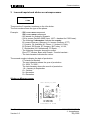
Communications
Repair Manual
Gigaset C350, C355
up to level 2.5
Confidential
Version 1.0
1
COM MD CC GRM T
J. Junggebauer
July 2005
Communications
1 Table of contents
1
TABLE OF CONTENTS .............................................................................................................................2
2
PROCEDURES.............................................................................................................................................3
2.1
2.2
SERVICE PROCEDURES FOR THE HANDSET ..............................................................................................3
SERVICE PROCEDURES FOR GIGASET C 350 AND 355.............................................................................4
3
LASERED IMPRINT AND STICKER ON MICROPROCESSOR........................................................6
4
TEST AND IDENTIFICATION OF FAULTY COMPONENT ..............................................................7
4.1
4.2
4.3
4.4
4.5
5
BLOCK DIAGRAMS ................................................................................................................................10
5.1
5.2
5.3
6
BLOCK DIAGRAM HANDSET .................................................................................................................10
BLOCK DIAGRAM C350 BASE STATION ................................................................................................11
BLOCK DIAGRAM C355 BASE STATION ................................................................................................12
REPAIR OF HANDSET ............................................................................................................................13
6.1
6.2
6.3
6.4
6.5
6.6
6.7
6.8
6.9
6.10
6.11
7
CHECK OF COMPLETE SYSTEM WITH FAULT DESCRIPTION OF CUSTOMER ...............................................8
CHECK OF COMPLETE SYSTEM WITHOUT FAULT DESCRIPTION OF CUSTOMER ........................................8
CHECK OF COMPONENT WITH FAULT DESCRIPTION OF CUSTOMER .........................................................8
CHECK OF COMPONENT WITHOUT FAULT DESCRIPTION OF CUSTOMER ...................................................8
FUNCTIONAL TEST .................................................................................................................................9
SPECIAL EQUIPMENT AND TOOLS .........................................................................................................13
DISASSEMBLING OF HANDSET ..............................................................................................................14
ASSEMBLING OF HANDSET ...................................................................................................................17
EXPLODED VIEW OF HANDSET..............................................................................................................17
BOARD LAYOUT OF HANDSET ..............................................................................................................18
HUMIDITY OR LIQUID DAMAGE ............................................................................................................19
EARPHONE CAPSULE/ RECEIVER FAULTY .............................................................................................20
LOUDSPEAKER FAULTY........................................................................................................................21
DISPLAY COVER BROKEN OR SCRATCHED ............................................................................................22
DISPLAY MODULE FAULTY ...................................................................................................................23
MICROPHONE FAULTY .........................................................................................................................28
REPAIR OF BASESTATION...................................................................................................................29
7.1
7.2
7.3
7.4
7.5
7.6
7.7
7.8
7.9
7.10
7.11
DISASSEMBLING OF BASE STATION C350.............................................................................................29
DISASSEMBLING C355 .........................................................................................................................31
ASSEMBLING C350 AND C355 .............................................................................................................31
EXPLODED VIEW C350/ C340 ..............................................................................................................32
EXPLODED VIEW C355/ C345 ..............................................................................................................33
BOARD LAYOUT C350 .........................................................................................................................34
BOARD LAYOUT C355 .........................................................................................................................35
LIGHTNING STROKE DAMAGE...............................................................................................................36
LOUDSPEAKER FAULTY........................................................................................................................37
CHARGING PROBLEMS .........................................................................................................................38
LINE SEIZURE PROBLEMS .....................................................................................................................39
Confidential
Version 1.0
2
COM MD CC GRM T
J. Junggebauer
July 2005
Communications
2 Procedures
Since the C350/ 355 is a C340/ C345 in a PTT design housing, all procedures
are identical.
Hidden service procedures for the handset and base stations.
Note: The service procedures are confidential.
2.1
Service procedures for the handset
Read out IPUI of the handset (for identification purposes): menu-key, *, #, 0, 6, #
Press 1, 4 and 7 simultaneously and keep keys pressed
Switch on and keep key pressed until "SERVICE" is visible, then release
all keys
Press 4685463 (HOTLINE)
This code performs a fundamental reset on
the handset. All settings are reset to factory
defaults. Handset is still registered to base.
Press 76200
Service-menu is displayed with following items:
SW-version, QS-data, Speechpath test, Battery
mode, DSP-parameters, Metering mode,
Measure time, Working time, Contrast, SAR.
Red items are only for Development Department
or Quality Assurance and not explained here!
SW-version: Read out SW-version and IPUI (international portable user identity) of
handset. IPUI is a unique number (like IMEI) that could be used for identification.
Speechpath-test: Switches a direct loop between microphone and loudspeaker.
This enables a check of the speechpath by blowing in the microphone.
Metering mode: Press o.k. to activate an information line during normal operation
mode and leave the service menu afterwards.
Example:
100 - 0 - 02 - 016 - 100
RX-level - Frequency - Time slot - Base code - Bit error rate (100 = 100% o.k.)
Measure time: Changes the measure time of the metering mode (change is not
necessary).
Working time: Read out the time for which the handset has been switched on.
Example: 15d, 10h means handset has been switched on for 15 days and 10 hours.
The counter's max. value is 65535 hours or 2730 days. It can only be reset at WSC.
Contrast: Changes the contrast of the display.
Confidential
Version 1.0
3
COM MD CC GRM T
J. Junggebauer
July 2005
Communications
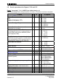
2.2
Service procedures for Gigaset C 350 and 355
Press: "menu-key", 5, 4, 9, ABCD (see table below), o.k.
Pos. acknowledge tone (rising sequence of notes) = Procedure has been accepted.
Feature
Read out RFPI number of base station
Pause after access code
and
length of dial pause ("P")
A
1
1
B
-
Pause after signal-key
1
-
Automatic attenuation correction
(dependant on country)
Time for end of call identification
(to distinguish between 2 ringing pulses of
one call with long pauses between pulses
and 2 separate calls)
1
-
1
-
Hook-flash-prevention (cradle switch
identification) (short press on cradle switchkey is extended by SW to prevent that it is
interpreted as a press on the flash-key)
Pause after line seizure
1
-
1
-
Music on hold
Read customer settings
1
1
-
Suppress first call if SMS is activated
System PIN reset
Programming data on an address
Read out SW-version
(decimal figures)
1
3
4
4
76200
76200
76200
Range of ringing frequency recognition
4
76200
Dial pulsing:
pulse pause ratio (make break ratio)
CLIP list activation
Off-hook CLIP activation
Approval test
Working time
4
76200
4
4
6
7
76200
76200
76200
-
Confidential
Version 1.0
4
C
D (Option)
0
1 1 = 1 sec.
2 = 2 sec.
3 = 3 sec.
4 = 6 sec.
2 1 = 800 ms
2 = 1600 ms
3 = 3200 ms
3 0 = off
1 = on
4 0 = 4 sec.
1 = 5.5 sec.
2 = 7 sec.
3 = 11 sec.
4 = 2.5 sec.
5 0 = 800 ms
1 = 2000 ms
6 1 = 1 sec.
2 = 3 sec.
3 = 7 sec.
7 0 = off 1 = on
8
- (see
description below) *
9 0 = no 1 = yes
1 Specific code needed
2 Example: 0100200 …
01 = SW-variant
002 = SW-version
00 = Revision
3 0 = 20- 60 Hz
1 = 15- 75 Hz
2 = other settings
4 0 = 1.5 : 1
1= 2 :1
5 0 = on 1 = off
6 0 = off 1 = on
5
1
- see **
COM MD CC GRM T
J. Junggebauer
July 2005
Communications
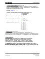
*
Read customer settings (menu, 54918):
Menu for Hotline purposes that enables to check some customer settings in 1
procedure. Instead of asking the customer which flash time…he has said he just
needs to tell the Hotline this special code.
Example: 110000 - 1 - 1 - 3
The first 6 characters show the registered handsets from 1 to 6:
0 = not subscribed
1 = subscribed
The 1 indicates the repeater mode: 0 = off
1 = on
The 1 stands for the dial mode:
1 = DTMF
2 = Dial pulsing
3 = DTMF + Earth
The 3 stands for the flash time:
0 = 80 ms
1 = 100 ms
2 = 120 ms
3 = 180 ms
4 = 250 ms
5 = 300 ms
6 = 600 ms
7 = 800 ms
** Working time (menu, 54971):
Read out the time for which the base station has been switched on.
Example: 15d, 10h means handset has been switched on for 15 days and 10 hours.
The counter's max. value is 65535 hours or 2730 days. It can only be reset at WSC.
Fundamental reset:
Disconnect mains. Press paging key on base station and hold down.
Plug in AC- adapter. Hold key pressed for more than 3 seconds.
Release paging key. The base station is now set to factory defaults.
The system-PIN is reset to 0000 and all mobile units are deregistered.
If a handset was registered only to this base station before the reset, it can be
registered automatically after a location update with the base station (after appr.
30 seconds or after picking up the handset (off hook key).
Confidential
Version 1.0
5
COM MD CC GRM T
J. Junggebauer
July 2005
Communications
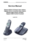
3 Lasered imprint and sticker on microprocessor
S30852-S1607-N161
...............
CT/S5
These are the 2 important numbers on the info sticker.
The first number shows the type of the phone.
Example:
- S30 means new component
S36 means swap component
- 852 stands for analogue Gigasets
- S16xx means Portfolio 2004 (here: 1607 = handset for C350 base).
- The following 2 characters indicate the country.
B1 means Germany (Siemens); A1 means Germany (PTT)
C1 Austria, C4 Australia, N1 France, V1 Ireland, K1 Italy,
S2 Poland, S3 Russia, S7 Hungary, B4 Turkey, L1 UK,
F1 Switzerland, M1 Netherlands, D1 Spain, .....
- The following character shows the variant.
Euro-PTT-Version, Base with Classic-/ Comfort handset...
- The last character indicates the colour.
The second number indicates the date of production.
CT stands for Bocholt.
The next character shows the year of production.
S = 2004, T= 2005 …
The last character shows the month of production.
1-9 = January to September
O = October
N = November
D = December
Sticker on Microprocessor:
Date: March,11,2004
S311
T
I
M
E
L
I
N
E
S
T
A
T
E
Partnumber of board
Confidential
Version 1.0
6
COM MD CC GRM T
J. Junggebauer
July 2005
Communications
4 Test and identification of faulty component
Not all incoming components or systems have to be faulty.
The customer could have problems with the operation of the phone or
could have placed it close to a device (PC...) that affects it.
It could also happen, that there is a loose connection in the phone
(due to a dry joint or something else).
So the fault might not appear during test.
There are different possibilities to test a phone depending on the information
attached.
Confidential
Version 1.0
7
COM MD CC GRM T
J. Junggebauer
July 2005
Communications
4.1
Check of complete system with fault description of customer
Try to reconstruct the fault using the description of the customer.
Check the batteries and the AC-adapter.
Find out whether the customer has programmed something wrong
by checking the procedures concerned.
If that was not successful do an incoming test.
If there is a fault try to find out which component is faulty by registering on a
golden device and testing again (deregister it from the golden device after testing).
Register a swap component to the customer component.
4.2
Check of complete system without fault description of customer
Check the batteries and the AC-adapter if existing.
Perform an incoming test.
If there is a fault try to find out which component is faulty by registering at a
golden device and testing again (deregister it from the golden device after testing).
Register a swap component to the customer component.
4.3
Check of component with fault description of customer
Register component to golden device.
Try to reconstruct the fault using the description of the customer.
Check the batteries (handset) or the AC-adapter (base station).
Find out whether the customer has programmed something wrong
by checking the procedures concerned.
If that was not successful make an incoming test.
Deregister customer device from golden device after testing.
4.4
Check of component without fault description of customer
Register component to golden device.
Check the batteries (handset) or the AC-adapter (base station).
Make an incoming test.
Deregister customer device from golden device after testing.
Confidential
Version 1.0
8
COM MD CC GRM T
J. Junggebauer
July 2005
Communications
4.5
Functional Test
There is an incoming and an outgoing test.
The difference between them is that in the outgoing test you do a reset
on the component after testing in case of swap (to deregister, reset PIN and set to
factory defaults). For personalized repair outgoing test is the same as incoming test.
Outgoing test (system):
1)
Displaytest:
Mobile unit is switched off.
Press 1, 4 and 7 simultaneous and hold down while switching on.
Press any key to alter pattern.
2)
Charging-test:
Mobile unit is switched off.
Put mobile unit into charging cradle/ base station.
One segment of the battery display has to start blinking automatically
when putting in.
3)
There are 2 possibilities of testing the fundamental functions of the telephone:
1) Test with PBX (private branch exchange):
a) Ringer test handset and base station
b) Dialling test
c) Audio test in transmit and receive direction (speech)
with the help of a second phone (corded) connected to the PBX.
2) Test with telephone tester, if existing (e.g. WPG 1000):
- Ringer test (not for Comfort base stations)
- DC resistance and isolation resistance (only for base station test)
- Testing the dial information (only for base station test)
- Testing the flash hookswitch (signal key) (only for base station test)
- Audio test of telephone in transmit direction (SLR)
- Audio test of telephone in receive direction (RLR)
4)
Do a fundamental reset on the base station you want to test in case of swap:
Disconnect mains.
Press paging key and hold down.
Plug in AC- adapter.
Hold key pressed for appr. 3 seconds. Release paging key.
The base station is now set to factory defaults.
The system code is set to 0000 and all mobile units are deregistered.
5)
Reset handset to factory defaults in case of swap:
Switch off the handset, press 1, 4 and 7 simultaneously and keep pressed while
switching on. Press 4685463 (HOTLINE).
This resets the handset completely. It is still registered to the base station.
Incoming test:
Confidential
Version 1.0
only step 1 to 3
9
COM MD CC GRM T
J. Junggebauer
July 2005
Communications
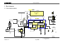
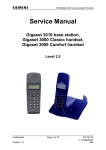
5 Block diagrams
5.1
Block diagram handset
HF-Amp
integ. SC14430
Antenna
VBAT (3.6V max)
RF- module
NSC
3.3V
HSG
VDD 1.8V
VDCDC
SC 14430
Adaptationunit
HF
Charging-contact
DC/ DC
converter
3.3V
Chargingswitch
Amp
LDO 1.8V
LDO 2.5V
EMCfilter
UP (CR 16B)
PowerControl
416 KByte
Temp.
Sensor
Akk
u
Keypad
on/offkey
Analog
Front
End
DSP +
Hands Free Ctrl.
BMC
2x
AAA
11.5KByte
Grafik
LCD-module
64 x 101 Dots
EE PROM
8 KByte
SEND
SP LED
MWI
IAkku
Confidential
Version 1.0
10
COM MD CC GRM T
J. Junggebauer
July 2005
RD CP 1
04 06 03 /
Communications
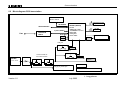
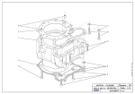
5.2
Block diagram C350 base station
serial EEPROM
8K x8 or 16k x 8
Paging Switch also usable
for registration of mobiles
I2C-Interface
SC14438 (National)
- µP DIP
- 5MBit Flash / ROM
- 10,5kB RAM+11,5 shared
- DECT-DSP
- Analog Part
- 64 Pin TQFP
V24 Test-Interface
Crystal10,368MHz
Universal-LIF
ICTR 37
Line
RESQ
1,8V
LIU o. MWI
Not implemented
HF-Modul (National)
2,5V
2,5V
LDO_2.5
2,5V IO/RF
LDO_1.8
Infinineon TLE4308 und
IFX1117GSV succession
1,8V BB
AC-NAG
3,3V PA +Synth.
max 3,6V
9,5V AC 300 mA
Charging for portable parts
ca. 150 mA DC
reduced current of 6mA if RF-Connection established
Confidential
Version 1.0
11
COM MD CC GRM T
J. Junggebauer
July 2005
Communications
10,368MHz
2
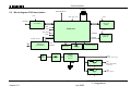
5.3
Testschnittstelle I C
Block diagram C355 base station
+3V3
+1V8, +2V5, +3V3
+3V3
Amt (a/b)
Step 9 –HF
(Philips)
Line Interface
VBAT
VEGA Bluebird
VR1_CTRL
+8V0
VR2_CTRL
SPEAKER
JTAG
SPKENQ
LH-Verstärker
MC34119
CHARGE
CHARGE_DETECT
Lade-schaltung
150mA/1mA
(nicht Andalucia)
NAG
-C373
+8V0
Keypad
(8/28Tasten)
Graifik-Display
(nur Andalucia-AM)
1 / 5+4 LED
Infineon
TLE 4308 +
IFX1117
+3V3
(VDDIO, HF-Teil, LineInt.)
+8V0
+2V5
(VDDA, VDDINT, VDDO
mit Sense-Pin)
VR1_CTRL
+1V8
(VDDC, VDDPLL)
VR2_CTRL
Confidential
Version 1.0
12
COM MD CC GRM T
J. Junggebauer
July 2005
Communications
6 Repair of handset
ESD regulations have to be followed in the complete repair process!
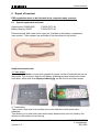
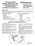
6.1
Special equipment and tools
Opening-tool G2000/4000
Battery-dummy G5000
F30032-P175-A1
F30032-P270-A1
Recommended: Self-made tool to open the 2 latches in the battery compartment
(see picture). Take a paper clip and folder it like described on the picture.
Helpful self-made tools:
1. Foam shape:
Take a piece of foam, cut and stick together the parts, so that it looks like the tool on
the picture. This is a good help for the display soldering process, because the lower
case shell, which acts as a display soldering jig can be fixed in this foam shape.
2. Testhousing:
Take a lower case shell of a handset and cut the latches on both sides with a
sidecutter.
That allows you to open both case shells easily because they are only fixed by the
latches on the bottom and on the top.
Confidential
Version 1.0
13
COM MD CC GRM T
J. Junggebauer
July 2005
Communications
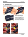
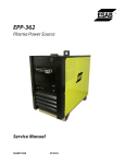
6.2
Disassembling of handset
1. alternative (recommended): Insert the self-made paper clip tool between the 2
latches in the battery compartment like (see picture below) and turn it a little.
The open latches should look like
shown on the picture.
The opening procedure with this paper
clip tool is the easiest way to do the
first step in opening the housing.
Alternatively it is also possible with the
opening tool G2000/ 4000 but not as
easy as that and it could scratch the
case shell. Nevertheless it is also
described on the 4 pictures below.
2. alternative (not recommended):
Confidential
Version 1.0
14
COM MD CC GRM T
J. Junggebauer
July 2005
Communications
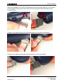
Insert the opening tool G2000/ 4000 between both case shells and turn it in direction
to the keypad. Do the same at the latch on the microphone like described on the
pictures below.
Continue with opening doing the same procedure on the other side latches.
Continue with opening doing the same procedure on the top latches.
Confidential
Version 1.0
15
COM MD CC GRM T
J. Junggebauer
July 2005
Communications
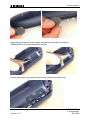
Open the last 2 latches in the battery compartment with the opening tool
G2000/40000 or the self-made paper clip tool.
Now all latches are open and the upper case shell can be picked up.
Confidential
Version 1.0
16
COM MD CC GRM T
J. Junggebauer
July 2005
Communications
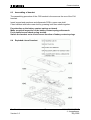
6.3
Assembling of handset
The assembling procedure of the C35 handset is the same as the one of the C34
handset.
Insert keypad and earphone and afterwards PCB in upper case shell.
Close handset with lower case shell by pressing both case shells together.
Pay attention on the battery contact springs on board.
Make an optical inspection of the battery contact springs afterwards.
Put in batteries and check spring tension.
Switch the handset on to check correct function of battery contact springs.
6.4
Exploded view of handset
Confidential
Version 1.0
17
COM MD CC GRM T
J. Junggebauer
July 2005
Communications
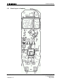
6.5
Board Layout of handset
Confidential
Version 1.0
18
COM MD CC GRM T
J. Junggebauer
July 2005
Communications
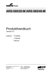
6.6
Humidity or liquid damage
Diagnosis code IRIS:
-
61000 (DEVICE / MOISTURE DAMAGE)
Boards with oxidation on the keypad side do not have to be scrapped if the vias
are not affected by green oxidation layer. Æ Clean board
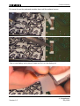
Boards with humidity damages on the component side have to be scrapped.
Look at all electronic components on the back side. Do not open the RF-Part.
Remaining flux on the component side could look similar to a humidity damage (white
deposits) but it will disappear when heating it up with a hot air blower.
no scrap:
Scrap:
Check also area under display!
Via
Confidential
Version 1.0
19
COM MD CC GRM T
J. Junggebauer
July 2005
Communications
6.7
Earphone capsule/ receiver faulty
Affected unit:
Handset
Diagnosis code IRIS:
72100 (ACOUSTICS / RECEIVING / EARCAP)
Repair level:
Level 1
Components:
Earphone capsule/ receiver
Needed equipment:
Multimeter
Working material:
None
Diagnosis:
The diaphragm of the earphone could be affected by deposits with increasing age.
There will be a higher attenuation when measuring RLR (receiving loudness rating).
In most cases the earphone capsule is defective.
If there is no noise audible on the earphone when making a sidetone check it’s also
possible that the wire of the coil is broken.
Check the resistance of the coil with a multimeter.
The typical resistance is appr. 120 ohms. In other cases replace it.
Repair:
Replace earphone capsule.
Test:
Put the repaired board in a testhousing.
Make a sidetone check by blowing into the microphone and checking the volume
of the noise on the earphone.
If there is a telephone tester with acoustic testhead make a RLR-test and check
whether the attenuation is o.k..
Confidential
Version 1.0
20
COM MD CC GRM T
J. Junggebauer
July 2005
Communications
6.8
Loudspeaker faulty
Affected unit:
Handset
Diagnosis code IRIS:
72200 (ACOUSTICS / RECEIVING / LOUDSPEAKER)
Repair level:
Level 1
Components:
Loudspeaker
Needed equipment:
Multimeter
Working material:
None
Diagnosis:
The diaphragm of the loudspeaker could be affected by dust or humidity or the
loudspeaker could be electrically faulty.
Make a sidetone check (service-menu) in order to check the sound of the speaker.
If there is no sound, check the resistance of the coil with a multimeter.
The typical resistance is appr. 15-16 ohms. In other cases replace it.
Repair:
Replace loudspeaker.
Test:
Put the repaired board in a testhousing.
Make a sidetone check by blowing into the microphone and checking the volume
of the noise on the loudspeaker.
Confidential
Version 1.0
21
COM MD CC GRM T
J. Junggebauer
July 2005
Communications
6.9
Display cover broken or scratched
Affected unit:
Handset
Diagnosis code IRIS:
23100 (DISPLAY / MECHANICAL DEFECT / SCRATCHES)
Repair level:
Level 1
Components:
Display cover
Needed equipment:
Screwdriver
Working material:
None
Diagnosis:
Display cover broken or scratched.
Repair:
Replace display cover.
Open the 2 latches on the bottom with a screwdriver(1).
Then lift the display carefully until the 2 latches on the top open (2).
To reassemble the display you just need to press the new cover gently on its place.
(2)
(1)
Test:
Do a display test after replacement.
Confidential
Version 1.0
22
COM MD CC GRM T
J. Junggebauer
July 2005
Communications
6.10 Display module faulty
Affected unit:
Handset
Diagnosis code IRIS:
21100 (DISPLAY / PERFORMANCE / NO LETTERS)
21200 (DISPLAY / PERFORMANCE / LINE-/COLUMN ERROR)
23200 (DISPLAY / MECHANICAL DEFECT / DISPLAY BROKEN)
Repair level:
Level 2.5
Components:
Display module
Needed equipment:
50 watts soldering station Weller WTCP 50 or WS (D) 50,
Soldering tip FP7, small soldering tip
Working material:
Flux Kester 952 S, scotch tape
Diagnosis:
Missing lines, columns, display does not work at all or display (LCD) broken.
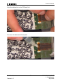
Repair:
Adjust the soldering station to 370°C (only for WS(D) 50).
Insert board in testhousing case shell (see chapter 6.1).
Fix case shell in foam shape.
Get off faulty display by soldering the soldered joints and pulling the display foil as
described on the picture below.
Pictures are taken from G5000.
Confidential
Version 1.0
23
COM MD CC GRM T
J. Junggebauer
July 2005
Communications
Put some flux on the pads and resolder them until the surface is even.
Take a new display and a piece of tape and fix it on the display foil.
Confidential
Version 1.0
24
COM MD CC GRM T
J. Junggebauer
July 2005
Communications
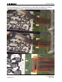
Align the display foil on the PCB and fix it.
Put some flux between foil and pads.
Confidential
Version 1.0
25
COM MD CC GRM T
J. Junggebauer
July 2005
Communications
Put the soldering tip FP7 on the soldering iron and solder the display in 2 steps as
described in the picture below. The result should look like the last picture.
Confidential
Version 1.0
26
COM MD CC GRM T
J. Junggebauer
July 2005
Communications
Fix the display foil with a finger and gently remove the tape.
Test the soldered connection by gently pulling the display foil.
Test:
Do a display test. Press 1,4 and 7 simultaneously and keep pressed while switching
on the handset. Release all keys.
Press a key. You must test patterns on the display. Press another key in order to
change test patterns. Do this a few times until the first test pattern is visible.
Confidential
Version 1.0
27
COM MD CC GRM T
J. Junggebauer
July 2005
Communications
6.11 Microphone faulty
Affected unit:
Handset
Diagnosis code IRIS:
73110 (ACOUSTICS / TRANSMITTING / MICROPHONE / NO FUNCTION)
73170 (ACOUSTICS / TRANSMITTING / MICROPHONE / LOW VOICE LEVEL)
Repair level:
Level 2.5
Components:
Microphone
Needed equipment:
Soldering iron
Working material:
Desolder wick, solder
Diagnosis:
The diaphragm of the microphone is affected by humidity or nicotine with increasing
age or the microphone could be electrically faulty. There will be a higher attenuation
when measuring SLR (sending loudness rating). In most cases the microphone is
defective.
Repair:
Remove the microphone by desoldering the 2 solder joints.
You can also heat up both pins simultaneously with a broad soldering iron tip and
turn the board upside down, letting the microphone fall out.
Clean pads with desoldering wick and replace it by a new component afterwards.
Attention: Avoid excessive heat (2 seconds maximum)!
Test:
Put the repaired board in a testhousing.
Make a sidetone check by blowing into the microphone and checking the volume
of the noise on the earphone.
If there is a telephone tester with acoustic testhead make a SLR-test and check
whether the attenuation is o.k..
Confidential
Version 1.0
28
COM MD CC GRM T
J. Junggebauer
July 2005
Communications
7 Repair of basestation
The procedures are absolutely the same as for G340/ G345.
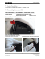
7.1
Disassembling of base station C350
ESD regulations have to be followed in the complete repair process!
Needed material:
Suitable screw driver with cross recess,
Opening-tool G2000/4000
F30032-P175-A1
Unscrew the 3 screws of the lower case shell.
Insert the opening tool G2000/4000
Between both case shells and turn it
until the latch opens (click noise).
Confidential
Version 1.0
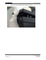
Afterwards do the same on the other side.
29
COM MD CC GRM T
J. Junggebauer
July 2005
Communications
Open the housing as described on the picture below.
Confidential
Version 1.0
30
COM MD CC GRM T
J. Junggebauer
July 2005
Communications
7.2
Disassembling C355
Needed material: suitable screw driver with cross recess
Unscrew the 6 screws on the lower case shell and lift it.
7.3
Assembling C350 and C355
Needed material: suitable screw driver with cross recess
Put charger contact springs in upper case shell.
Insert keypad.
Put board in upper case shell.
Insert loudspeaker (only C355).
C355:
Attach the other case shell and close the device by screwing the 6 screws in the
lower case shell.
C350:
Attach the other case shell and close the device by closing the latches and screwing
the 3 screws in the lower case shell.
Make sure that the charging contact springs are fixed correctly.
Confidential
Version 1.0
31
COM MD CC GRM T
J. Junggebauer
July 2005
Communications
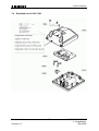
7.4
Exploded view C350/ C340
Confidential
Version 1.0
32
COM MD CC GRM T
J. Junggebauer
July 2005
Communications
7.5
Exploded view C355/ C345
Confidential
Version 1.0
33
COM MD CC GRM T
J. Junggebauer
July 2005
Communications
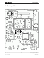
7.6
Board Layout C350
Confidential
Version 1.0
34
COM MD CC GRM T
J. Junggebauer
July 2005
Communications
7.7
Board Layout C355
Confidential
Version 1.0
35
COM MD CC GRM T
J. Junggebauer
July 2005
Communications
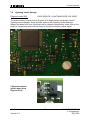
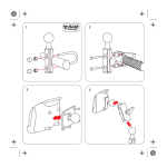
7.8
Lightning stroke damage
Diagnosis code IRIS:
62000 (DEVICE / LIGHTNING/OVER VOLTAGE)
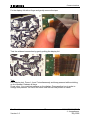
The picture below is taken from a Gigaset 4010 base station and shows a small
lightning stroke damage. Scrap all base stations with lightning stroke damage.
Inspect the board with your eyes and look for chipped components, black soot on the
board or components that look like those on the picture below (yellow signs).
Chipped transistor
(photo taken from
Gigaset 2010)
Confidential
Version 1.0
36
COM MD CC GRM T
J. Junggebauer
July 2005
Communications
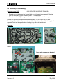
7.9
Loudspeaker faulty
Affected unit:
Gigaset C355
Diagnosis code IRIS:
72200 (ACOUSTICS / RECEIVING / LOUDSPEAKER)
Repair level:
Level 1
Components:
Loudspeaker
Needed equipment:
Screwdriver or similar tool, multimeter
Working material:
none
Diagnosis:
The diaphragm of the loudspeaker could be affected by dust or humidity or the
loudspeaker could be electrically faulty. Check the sound of the speaker.
If there is no sound, measure the resistance of the coil with a multimeter.
The resistance should be appr. 18 ohms. In other cases replace it.
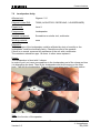
Repair:
The loudspeaker is fixed with 2 clamps.
In order to get it out insert a screwdriver in the loudspeaker part of the clamp and turn
it to disengage the hook. Then lift the loudspeaker and do the same on the other
hook. Take out the loudspeaker. Pictures below are taken from C150 base station.
Test:
Check the function of the speaker.
Confidential
Version 1.0
37
COM MD CC GRM T
J. Junggebauer
July 2005
Communications
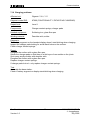
7.10 Charging problems
Affected unit:
Gigaset C350, C355
Diagnosis code IRIS:
97000 (FUNCTIONALITY / DEVICE NO CHARGING)
Repair level:
Level 1
Components:
Charger contact springs, charger pads
Needed equipment:
Soldering iron, glass fibre pen
Working material:
Desolder wick, solder
Diagnosis:
The battery segment on the handset display doesn’t start blinking when charging.
Inspect the charger pads looking for small black holes on the surface.
Check charger contact springs.
Repair:
Roughen the surface with a glass fibre pen.
Solder the charger pads so that there is a thin layer of new solder on the joints.
Suck away surplus solder with desolder wick.
Roughen the surface with a glass fibre pen.
Replace charger contact springs.
If charger pads look o.k. only replace charger contact springs.
Test:
Assemble the base station.
Check if battery segment on display starts blinking when charging.
Confidential
Version 1.0
38
COM MD CC GRM T
J. Junggebauer
July 2005
Communications
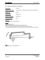
7.11 Line seizure problems
Affected unit:
Gigaset C350, C355
Diagnosis code IRIS:
93000 (FUNCTIONALITY / CALLING PROBLEMS)
Repair level:
Level 2.5
Components:
Philips IC PHC2300 or alternative component
Needed equipment:
Hot air blower, soldering iron, multimeter
Working material:
Flux, solder
Diagnosis:
Line seizure is not possible or connection can not be released. The IC PHC2300 (or
alternative component) consists of 2 transistors and is responsible for line seizure.
Measure the 2 transistors with a multimeter.
Confidential
Version 1.0
39
COM MD CC GRM T
J. Junggebauer
July 2005
Communications
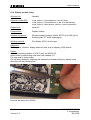
Repair:
Desolder the IC and solder a new component with a hot air blower.
Put some flux on the joints and resolder them with a soldering iron.
If necessary put additional solder on the joints.
Test:
Assemble the base station and connect it to a PBX or PSTN line.
Pick up the handset and dial the extension of another phone connected to the PBX or
PSTN. Establish a connection, test the speech path and release it afterwards.
Pick up the other phone and dial the extension of the repaired phone.
Accept the call on the repaired phone.
If the line seizure in both ways works the base station is o.k.
Confidential
Version 1.0
40
COM MD CC GRM T
J. Junggebauer
July 2005