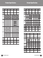
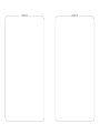
1
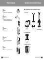
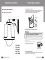
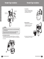
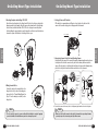
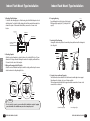
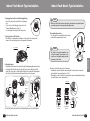
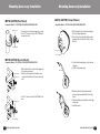
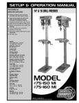
Before attempting to operate this product,
please read the instructions carefully.
SPD-3750T/3750/3700T/3700/3350/3310/2510
Speed Dome Camera Accessories
Installation Manual
STH-380PO/STH-370PO/STH-360PO
STH-370PI/STH-370PE
STB-370PC/STH-270PWV/STB-496PPV
STB-25PF/STB-30PF/STB-350PPM
STB-330PPM/STB-340PCM/STB-270B
Cautions and Warnings for Use
Samsung Techwin cares for the environment at all product manufacturing stages
to preserve the environment, and is taking a number of steps to provide
customers with more environment-friendly products. The Eco mark represents
Samsung Techwin's will to create environment-friendly products, and indicates
that the product satisfies the EU RoHS Directive.
Thank you for purchasing our products.
This product is to be used for the installation of the Samsung Speed Dome
Camera series: SPD-3750T, 3700T, 3750, 3700, 3350, 3310, and 2510.
Before installation, please read the user’s manual carefully.
- Note that you need to carefully read all contents related to safety and application
methods before installation.
- When using the product, the cautions/warnings, usage directions, operating methods,
and instructions must all be observed.
- The power and cable connections should be made by a product installation specialist.
- Do not connect and use these accessories to products other than the Samsung Speed
Dome Camera Series.
- The locations for installing the accessory housing should be strong enough to fully
secure the accessories. All installations need to be carried out by experienced engineers.
- Do not use it for purposes other than the installation mentioned above.
- For product inquiries, please contact the retail shop where you bought the camera. The
use of equipment such as an aerial ladder while providing after-sales service shall be at
your expense.
2
SPEED DOME CAMERA ACCESSORIES
Table of Contents
1. Product Category …………………………………………………………………… 4
1.1. Housing Accessories… ………………………………………………………… 4
1.2. Interface Mounting Accessories………………………………………………… 5
1.3. Mounting Bracket Accessories… ……………………………………………… 5
2. Speed Dome Camera Installation Category… ……………………………………… 7
3. Pendant Type Installation…………………………………………………………… 8
3.1 Wall Mount Type Installation… ………………………………………………… 8
* Camera Wiring Diagram … ………………………………………………… 12
3.2 Ceiling Mount Type Installation… …………………………………………… 15
3.3 Indoor Flange Mount Type Installation … …………………………………… 17
4. On-Ceiling Mount Type Installation… …………………………………………… 21
5. Indoor Flush Mount Type Installation… ………………………………………… 25
6. Mounting Accessory Installation… ……………………………………………… 30
Product External Dimensions… …………………………………………………… 34
Product Specification… …………………………………………………………… 36
Contents By Product Model
STH-380PO… ………………………………………………………………………… 8
STH-370PO… ………………………………………………………………………… 8
STH-370PI… ………………………………………………………………………… 8
STH-370PE… ……………………………………………………………………… 25
STH-360PO… ………………………………………………………………………… 8
STH-270PWV… ……………………………………………………………………… 8
STB-496PPV………………………………………………………………………… 15
STB-370PC… ……………………………………………………………………… 17
STB-350PPM… …………………………………………………………………… 30
STB-340PCM… …………………………………………………………………… 30
STB-330PPM… …………………………………………………………………… 30
STB-30PF…………………………………………………………………………… 15
STB-270B…………………………………………………………………………… 30
STB-25PF…………………………………………………………………………… 17
SPEED DOME CAMERA ACCESSORIES
3
Product Category
■ 1. Product Category
■ 1.1. Housing Accessories
STH-380PO/STH-370PO/STH-360PO
: "Outdoor housing” with a built-in install base for the
Samsung Speed Dome Camera.
STH-380PO :
Ultra Low-Temperature Heavyweight(-40℃~50℃)
STH-370PO :
Low-Temperature Heavyweight(-20℃~50℃)
STH-360PO :
Low-Temperature Lightweight(-20℃~50℃)
Product Category
■ 1.2. Interface Mounting Accessories
STB-370PC
:“On-Ceiling Install Base Mount” for the Samsung
Speed Dome Camera.
■ 1.3. Mounting Bracket Accessories
STH-270PWV
: This “Wall Type Mount” is used for the installation of
STH-380PO,STH-370PO,STH-360PO,STH-370PI and
STB-25PF of the Samsung Speed Dome Camera.
STH-370PI
: "Indoor Housing” with a built-in install base for the
Samsung Speed Dome Camera.
STB-496PPV
: This “Ceiling Type Mount” is used for the installation
of STH-380PO,STH-370PO,STH-360PO,STH-370PI and
STB-25PF of the Samsung Speed Dome Camera.
STH-370PE
: “Indoor Flush Mount" with a built-in install base for the
Samsung Speed Dome Camera.
STB-25PF
: This “Indoor Flange” for the Samsung Speed Dome
Camera is useful to install the camera without a
housing.
4
SPEED DOME CAMERA ACCESSORIES
SPEED DOME CAMERA ACCESSORIES
5
Product Category
STB-30PF
: “Ceiling Type Flange” for the Samsung Speed Dome
Camera.
Speed Dome Camera Installation Category
■ 2. Speed Dome Camera Installation Category
Pendant Type
STB-350PPM
: Parapet Mount” for the installation of indoor or
outdoor housing of Samsung Speed Dome Camera
STB-330PPM
Wall Type Mount
Ceiling Type Mount
Indoor Flange Type Mount
: “Pole Mount” for the Samsung Speed Dome Camera.
On-Ceiling Mount Type
STB-340PCM
: “Corner Mount” for the Samsung Speed Dome
Camera.
Indoor Flush Mount Type
STB-270B
: "Setup Box" for the Samsung Speed Dome Camera.
6
SPEED DOME CAMERA ACCESSORIES
SPEED DOME CAMERA ACCESSORIES
7
Pendant Type Installation
STH-380PO/370PO/370PI/360PO
STH-380PO/370PO/370PI/360PO
■ 3. Pendant Type Installation
Pendant Type Installation
1. Securing Wall Bracket and Wiring
As shown in the picture, secure the wall bracket to the wall, and then pull the wires out
of the bracket. Please note that the STH-380PO housing requires an additional
installation of the fan heater adapter enclosed with the product.
■ 3.1 Wall Mount Type Installation
Fan Heater Adaptor
(STH-380PO Only)
Camera Adaptor
✽ To store the adaptor, the STB-270B Setup Box (Page 31) can be used.
Notes
• Do not connect the camera to a power outlet until the installation is complete. Supplying
power in the middle of the installation may cause fire or damage the product.
• STH-370PO requires an additional installation of the fan heater adapter enclosed with the
product. Connecting the fan heater to a power outlet used for the camera can cause fire or
accidents.
2. Preparing Housing
Open the hinged door at the bottom of the housing.
Hold the knob on the hinged door to open.
STH-380PO
STH-370PO
STH-360PO
STH-370PI
STH-270PWV
8
SPEED DOME CAMERA ACCESSORIES
Knob
3. Connecting Housing and Bracket
To prevent the housing from falling down during the installation process, hook the safety
cable on the bracket loop as shown in the picture.
SPEED DOME CAMERA ACCESSORIES
9
Pendant Type Installation
Fan Heater Connector
(Model: STH-370PO)
STH-380PO/370PO/370PI/360PO
STH-380PO/370PO/370PI/360PO
Fan Heater Adaptor
(STH-380PO Only)
Pendant Type Installation
5. Securing Housing
Check if the housing is properly attached
to the bracket, secure the housing to the
bracket with the enclosed screws.
Camera Adaptor
6. Wiring Terminal Cables
Connect the cables to the terminal block
on the hinged door. Once the wiring is
successful, close the hinged door.
Notes
• The STH-380 housing’s fan heater connector must be connected to its dedicated adapter
enclosed with the product.
• Make sure to hook the safety cable on the bracket loop before connecting the housing.
• Neglecting this caution may expose you to injury caused by a fallen housing.
4. Assembling Housing and Bracket
After hooking the safety cable, fit the housing into the fixture grooves on the bracket as
shown in the picture. When attaching, locate the "Samsung" logo on the housing facing
the center front.
✽ For the location of the wiring pins, please refer to the
“Camera Wiring Diagram” on the next page.
Logo
10
SPEED DOME CAMERA ACCESSORIES
SPEED DOME CAMERA ACCESSORIES
11
Pendant Type Installation
Pendant Type Installation
Video Output
Alarm
STH-380PO/370PO/370PI/360PO
STH-380PO/370PO/370PI/360PO
✽ Camera Wiring Diagram
This wiring diagram indicates the connection between the interface board and external
equipment. For wiring Samsung Techwin’s Speed Dome Camera and the accessories,
please refer to the Speed Dome Camera user’s manual.
7. Preparing Camera
Once the camera wiring is successful, prepare the
camera. Every housing-typed camera except the
flush model is provided with a dome cover first
detach the dome cover from the camera.
8. Setting Up Camera DIP Switches
DIP switches for communication and ID protocols are located on the bottom of the
camera. For the switch settings, refer to the appendix of this manual.
Alarm Output
Protocol(SW2)
ID(SW1)
Fan Heater
Connector
Alarm Input
Communications
and AUX
Power Supply
9. Connecting Camera Safety Cable and Attaching Camera
Carefully attach the camera to the mount following the alignment guide marks as shown in
the picture. First hook the camera's safety cable on the mount, and then attach the camera.
The safety cable is coiled inside the install base. As shown in the leftward picture, pull out
the safety cable from the install base and then hook it to the mount.
AC24V 2.5A
Power Input
Ground
Refer to the below Control
Signal Connection diagram
Safety
Cable
Alignment
Direction
Guides
AUX Output
Alignment
Directions
Control Signal Connection
· RS485 Communications
Camera
D+
D-
· RS422 Communications
Camera
D+
DTX+
TX-
12
Controller
or DVR
TXD+
TXDController
or DVR
TXD+
TXDRXD+
RXD-
SPEED DOME CAMERA ACCESSORIES
Alignment
Direction
Guides
Notes
• The maximum capacity of the alarm and
AUX output terminals is DC30V 2A.
• Connecting the power connector and GND
incorrectly to the NC/NO and COM ports
can cause a short circuit which may lead
to fire and damage the camera.
✽ To attach the camera to the mount, refer to the alignment guide marks as shown in the picture.
Notes
• Make sure to first hook the camera's safety cable to the mount before proceeding. Otherwise
you may be exposed to serious injury caused by a fallen camera.
SPEED DOME CAMERA ACCESSORIES
13
Pendant Type Installation
STH-380PO/370PO/370PI/360PO
STH-380PO/370PO/370PI/360PO
✽ To attach or detach the camera, refer to the picture.
* Attaching the camera: Hold up the camera and push it to the mount as shown in the
picture. Push the camera until you hear a “click”.
* Detaching the camera: To detach the camera, pull the camera downward while pushing
the unlock buttons on the camera upward.
Pendant Type Installation
■ 3.2 Ceiling Mount Type Installation
This guideline is based on the installation of the ceiling flange STB-30PF.
Unlock Button
UNLOCK
To attach the
camera
To detach the
camera
10. Assembling Dome Cover
Once the camera is successfully attached, secure
the mount with the transparent dome cover. Next,
turn on the power.
11. Dome Cover Setting
Once the installation is complete, please optimize
the camera focus settings. On the camera’s OSD
Menu, set the Dome Cover setting to Outdoor.
(Directory: Main Menu/Camera Setting/Others)
Others
14
Sync
Stabilizer
③ Image Adj
Freeze
Dome Cover INTERNAL
OFF
OFF
Outer
SPEED DOME CAMERA ACCESSORIES
STH-380PO
STH-370PO
STH-360PO
STH-370PI
STB-496PPV
STB-30PF
SPEED DOME CAMERA ACCESSORIES
15
Pendant Type Installation
Pendant Type Installation
STH-380PO/370PO/370PI/360PO
STH-380PO/370PO/370PI/360PO
■ 3.3 Indoor Flange Mount Type Installation
Camera Adaptor
Fan Heater Adaptor
(STH-380PO Only)
This guideline is based on the installation of the indoor flange STB-25PF and the
ceiling exposed mount STB-370PC.
Sealing Tape
SPSS32A/SCH40 Size Pipe
STB-30PF
PF 1 1/4"
1. Preparing Pipe and Ceiling Bracket
STB-30PF requires a SPSS32A/SCH40-sized pipe as shown in the picture. Assemble the
screw taps, and then wind a sealing tape around the screw barrel to prevent water leakage.
Please note that the STH-380PO housing requires an additional installation of the fan
heater adapter enclosed with the product.
Notes
• Using unsealed screw taps can cause the product to fall down or allow water leakage that
may lead to fire or damage the product. Sealing tape is not enclosed with the product, and
needs to be purchased at your expense.
2. Assembling STB-30PF and Pipe
After sealing the screw taps, assemble the STP-30PF flange securely to the pipe.
Notes
• Do not connect the camera to a power outlet until the installation is complete. Supplying
power in the middle of the installation may cause fire or damage the product.
✽ For the next installation procedures, refer to the “Wall Type Housing” installation from step 2.
16
SPEED DOME CAMERA ACCESSORIES
STB-370PC
STB-30PF
STB-25PF
STB-496PPV
STB-30PF
SPEED DOME CAMERA ACCESSORIES
17
Pendant Type Installation
STH-380PO/370PO/370PI/360PO
STH-380PO/370PO/370PI/360PO
1. Assembling Flange and Ceiling Exposed Mount (STB-370PC)
Wind sealing tape around the barrel of the screw taps, and then secure the STP-25PF flange
securely to the mount with the enclosed screws.
Pendant Type Installation
Notes
• Do not connect the camera to a power outlet until the installation is complete. Supplying
power in the middle of the installation may cause fire or damage the product.
4. Wiring Terminal Cables
Connect the cables to the terminal block on the hinged door. Once the wiring is successful,
close the hinged door.
Alignment Directions
Knob
2. Opening Hinged Door
Open the hinged door at the bottom of the housing.
Hold the knob on the hinged door to open.
3. Assembling Mount and Flange
First hook the safety cable on the mount, and then fit the housing into the fixture groove on
the bracket as shown in the picture. Once the housing is safely attached to the bracket,
secure the housing with the enclosed screws.
✽ For the location of the wiring pins, please refer to the “Camera Wiring Diagram” on Page 12.
5. Setting Up Camera DIP Switches
DIP switches for communication and ID protocols are located on the bottom of the camera.
For the switch settings, refer to the appendix of this manual.
ID(SW1)
Protocol(SW2)
CLOSE
18
SPEED DOME CAMERA ACCESSORIES
SPEED DOME CAMERA ACCESSORIES
19
Pendant Type Installation
STH-380PO/370PO/370PI/360PO
6. Attaching Camera
Carefully attach the camera to the mount following the alignment guide marks as shown in
the picture. First hook the camera's safety cable on the mount, and then attach the camera.
The safety cable is coiled inside the install base. As shown in the leftward picture, pull out
the safety cable from the install base and then hook it to the mount.
On-Ceiling Mount Type Installation
■ 4. On-Ceiling Mount Type Installation
This guideline is based on the installation of the indoor flange STB-370PC.
Alignment
Direction
Guides
Safety
Cable
Alignment
Direction
Guides
STB-370PC
Alignment
Directions
✽ To attach the camera to the mount, refer to the alignment guide marks as shown in the picture.
Notes
• Make sure to first hook the camera's safety cable to the mount before proceeding. Otherwise
you may be exposed to serious injury caused by a fallen camera.
✽ To attach or detach the camera, refer to the picture.
* Attaching the camera: Hold up the camera and push it to the mount as shown in the
picture. Push the camera until you hear a “click”.
* Detaching the camera: To detach the camera, pull the camera downward while pushing
the unlock buttons on the camera upward.
Unlock Button
UNLOCK
To attach the camera
20
SPEED DOME CAMERA ACCESSORIES
To detach the camera
STB-370PC
SPEED DOME CAMERA ACCESSORIES
21
On-Ceiling Mount Type Installation
1. Attaching Template and Installing STB-370PC
Attach the enclosed template to the ceiling, then drill a hole in the ceiling according to the
diameter marked on the template. Drop the camera cables down from the ceiling through
the hole. Next, install the Install Base STB-370PC to the ceiling as shown in the picture.
Before installing the exposed bracket, open the hinged door at the bottom of the bracket as
shown in the picture. Hold the knob on the hinged door to open.
Knob
3. Setting Up Camera DIP Switches
DIP switches for communication and ID protocols are located on the bottom of the
camera. For the switch settings, refer to the appendix of this manual.
ID(SW1)
Protocol(SW2)
STB-370PC
STB-370PC
Template
On-Ceiling Mount Type Installation
5. Connecting Camera Safety Cable and Attaching Camera
Carefully attach the camera to the mount following the alignment guide marks as shown
in the picture. First hook the camera's safety cable on the mount, and then attach the
camera. The safety cable is coiled inside the install base. As shown in the leftward picture,
pull out the safety cable from the install base and then hook it to the mount.
Safety
Cable
Alignment
Direction
Guides
Alignment
Direction
Guides
2. Wiring Terminal Cables
Connect the cables to the terminal block on the
hinged door. For the location of the wiring pins,
please refer to the “Camera Wiring Diagram” on
Page 12. Once the wiring is successful, close the
hinged door.
Alignment
Directions
✽ To attach the camera to the mount, refer to the alignment guide marks as shown in the picture.
Notes
• Do not connect the camera to a power outlet until the installation is complete. Supplying
power in the middle of the installation may cause fire or damage the product.
22
SPEED DOME CAMERA ACCESSORIES
Notes
• Make sure to first hook the camera's safety cable to the mount before proceeding. Otherwise
you may be exposed to serious injury caused by a fallen camera.
SPEED DOME CAMERA ACCESSORIES
23
On-Ceiling Mount Type Installation
✽ To attach or detach the camera, refer to the picture.
* Attaching the camera: Hold up the camera and push it to the mount as shown in the
picture. Push the camera until you hear a “click”.
* Detaching the camera: To detach the camera, pull the camera downward while pushing
the unlock buttons on the camera upward.
Indoor Flush Mount Type Installation
■ 5. Indoor Flush Mount Type Installation
This guideline is based on the installation of the flush mount STH-370PE.
Unlock Button
STB-370PC
UNLOCK
To detach the
camera
STH-370PE
To attach the
camera
STH-370PE
24
SPEED DOME CAMERA ACCESSORIES
SPEED DOME CAMERA ACCESSORIES
25
Indoor Flush Mount Type Installation
1. Attaching Flexible Adaptor
To feed the cables through a pipe to a flush housing, attach the flexible adaptor enclosed
with the product. To attach the flexible adaptor, the install base must be disassembled as
shown in the picture. To disassemble the install base, unscrew the 3 screws on the
bottom.
Silicon Cap
Indoor Flush Mount Type Installation
4. Preparing Housing
Open the hinged door at the bottom of the housing.
While pressing the spring lock (1), hold up the lid to
open (2).
Knob
Adaptor Nut
Flexible Adaptor
5. Inserting the flush housing
Arrange the cables and eyebolts as shown in the picture, and then insert the housing into
the ceiling hole.
Install Base(STB-370PC)
disassembly
Hanger Bolt
Fixing Nut
Eyebolt
Elbo bracket
Eyebolt
STH-370PE
STH-370PE
2. Attaching Template
Attach the enclosed template to a desired location on the ceiling. Drill 3 holes of 50 mm
diameter in 120-degree intervals following the marks on the template, and then drill one
200 mm hole in the center of the template.
3. Wiring and Arranging Anti-fall Eyebolts
Attach the enclosed turnbuckle and eyebolts inside the ceiling, and then drop the camera
cables down from the ceiling through the hole.
Turnbuckle
6. Securing Screws or Internal Supports
Two fixture methods are available for the flush mount: screw through or inner support.
Depending on the situation, select one of the two methods.
The inner support method unfolds the supports inside the mount when 3 screws on the
mount surface are fastened.
Eyebolt
Template
Φ200 mm
Ceiling
Template
Notes
• Do not connect the camera to a power outlet until the installation is complete. Supplying
power in the middle of the installation may cause fire or damage the product.
26
SPEED DOME CAMERA ACCESSORIES
Screw Through Type
Inner Support Type
SPEED DOME CAMERA ACCESSORIES
27
Indoor Flush Mount Type Installation
7. Arranging Camera Cables and Closing Hinged Door
Connect the cables to the terminal block on the hinged
door.
For the location of the wiring pins, please refer to the
“Camera Wiring Diagram” on Page 12.
Once the wiring is successful, close the hinged door.
Indoor Flush Mount Type Installation
Notes
• Make sure to first hook the camera's safety cable to the mount before proceeding. Otherwise
you may be exposed to serious injury caused by a fallen camera.
8. Setting Up Camera DIP Switches
DIP switches for communication and ID protocols are located on the bottom of the
camera. For the switch settings, refer to the appendix of this manual.
10. Assembling Dome Cover
Once the camera is successfully attached, secure the
mount with the transparent dome cover.
ID(SW1)
Protocol(SW2)
Notes
9. Attaching Camera
Carefully attach the camera to the mount following the alignment guide marks as shown
in the picture. First hook the camera's safety cable on the mount, and then attach the
camera. The safety cable is coiled inside the install base. As shown in the leftward picture,
pull out the safety cable from the install base and then hook it to the mount.
Safety
Cable
CLOSE
OPEN
STH-370PE
STH-370PE
• Be careful to not scratch the transparent cover
during the assembly. Scratched dome covers
may decrease the graphics quality and overall
performance of the camera.
✽ To attach or detach the camera, refer to the picture.
* Attaching the camera: Hold up the camera and push it to the mount as shown in the
picture. Push the camera until you hear a “click”.
*D
etaching the camera: To detach the camera, pull the camera downward while pushing
the unlock buttons on the camera upward.
Alignment
Direction
Guides
Unlock Button
Alignment
Direction
Guides
UNLOCK
Alignment
Directions
✽ To attach the camera to the mount, refer to the alignment guide marks as shown in the picture.
28
SPEED DOME CAMERA ACCESSORIES
To attach the
camera
To detach the
camera
SPEED DOME CAMERA ACCESSORIES
29
Mounting Accessory Installation
■ 6. Mounting Accessory Installation
Mounting Accessory Installation
■ STB-270B(Setup Box)
This guideline is to be used for the installation of mounting accessories for the
Samsung Speed Dome Camera series.
1. U
sing self drilling screws, secure the install
bracket.
2. F ill unwanted wire holes with mount caps.
Secure the mount cap with the mount cap
fastener.
MOUNT CAP
MOUNT CAP
FASTENER
3. P lace the setup box on the install bracket
as shown in the picture.
STH-370PE
STB-350PPM
STB-330PPM
4. U
sing hexagon bolts, fasten the setup box
to the bracket. Next feed the camera
cables into the setup box through the hole
in the cover.
STB-340PCM
30
SPEED DOME CAMERA ACCESSORIES
STB-270B
5. F eed the camera cables through the wall
bracket and secure the bracket using 4
screws.
6. L astly, fasten the screws using a hexagon
wrench to secure the bracket to the setup
box.
SPEED DOME CAMERA ACCESSORIES
31
Mounting Accessory Installation
Mounting Accessory Installation
■ STB-330PPM (Paul Mount)
■ STB-350PPM (Parapet Mount)
Compatible Models : STB-270PWV+STH-380PO/370PO/360PO/370PI
Compatible Models : STB-30PF+STH-380PO/370PO/360PO/370PI
Wall type mount
1. Secure the pole to the mount using a wire or cable.
2. U
se 4 1/4" screws to secure the STH-270PWV pole
mount to the wall.
1. D
rill 8 anchor bolt holes on the wall according to
the holes in the parapet mount.
2. U
sing a tool, insert anchor bolts and then set the
parapet mount on the bolts. Use 8 nuts to fasten
the bolts.
1/4" SCREW : 4EA
Parapet mount
Anchor bolt 8EA
■ STB-340PCM (Corner Mount)
3. F eed the cable through the pipe to the other end
of the pipe.
4. Set PPE on the parapet mount.
Compatible Models : STB-270PWV+STH-380PO/370PO/360PO/370PI
Anchor bolt 8EA
Corner mount
1. D
rill 8 anchor bolt holes on the wall according to the
holes in the corner mount.
2. U
sing a tool, insert anchor bolts and then set the
corner mount on the bolts. Use 8 nuts to fasten the
bolts.
3. Use 1/4" screws to secure the STH-270PWV to the
corner.
Wall type mount
PIPE
5. Wind the cable to the direction shown in the
picture, and then assemble the PPE cover using
screws.
6. Adjust the pipe direction, and then secure the pipe
using screws.
7. Install the camera.
1/4" SCREW : 4EA
32
SPEED DOME CAMERA ACCESSORIES
SPEED DOME CAMERA ACCESSORIES
33
Product External Dimensions
■ Wall Mounting
Product External Dimensions
Unit : mm
■ Ceiling Mounting
■ Ceiling Exposed Mounting
34
SPEED DOME CAMERA ACCESSORIES
Unit : mm
■ Indoor Flush Mounting
SPEED DOME CAMERA ACCESSORIES
35
Product Specifications
Product Specifications
Model
Item
Operating
Temperature
Range
STH-380PO
STH-370PO
STH-370PI
STH-370PE
STH-360PO
-40℃~50℃
-20℃~50℃
-10℃~50℃
-10℃~50℃
-20℃~50℃
0 to 90%RH
1 to 90%RH
0 to 90%RH
(non-condensing)
(non-condensing)
Housing
Housing
Housing
Embedded
Housing
ALDC 12
ALDC 12
ALDC 12
E.G.I (1.2t)
AL
Outdoor
Outdoor
Outdoor
Housing
Outdoor
Ring
Ring
Ring
Ring
Ring
Materials
ALDC 12
ALDC 12
ALDC 12
ABS
ALDC 12
Decoration
Decoration
Decoration
Decoration
Decoration
Dome
Poly
Dome
Poly
Dome
Poly
Dome
Poly
Cover
Carbonate
Cover
Carbonate
Cover
Carbonate
Cover
Carbonate
SAFETY
SUS
WIRE
(Φ1.2x
(1EA)
2000)
Turn
Eye Bolt
Components
Buckle1EA
2EA
(mm)
WIRE
JOINT(4EA)
Silicon
cap(1EA)
DC12V
DC12V
DC12V
0.06A
0.06A
0.06A
Operating
Operating
Operating
Temp
Temp
Temp
Fan(2EA)
Fan(2EA)
Fan(1EA)
More than
More than
More than
45℃
45℃
45℃
Less than
Less than
Less than
Miscellaneous
10℃
10℃
10℃
AC 24V
AC 24V
AC 24V
46W
33W
33W
Operating
Operating
Operating
Heater
Heater
Heater
Temp
Temp
Temp
less than
less than
less than
10℃
10℃
10℃
Antivibration/
Waterp
IP 67
IP 67
IP 67
IP 66
roof
Weight (Net)
3.2kg
3.2kg
3.2kg
740g
2.1kg
Weight
4.2kg
4.2kg
4.1kg
1.2kg
3.2kg
(Gross)
Dimensions
Φ242x284.5
Φ242x284.5
Φ242x284.5
Φ190x188.5
Φ242x284.5
(mm)
Humidity
0 to 90%RH
0 to 90%RH
Model
Item
Operating
Temperature
Range
STB-25PF
STB-270B
-40℃~50℃
-40℃~50℃
-10℃~50℃
-10℃~50℃
-40℃~50℃
0 to 90%RH
(non-condensing)
Housing E.G.I 2.0t
Flange
Adaptor
AL
Housing
1 to 90%RH
(non-condensing)
DOOR
ALDC 12
FRONT
BASE
ALDC 12
HOUSING
INSTALL
BRACKET C.R.2.0t
JOINT
1EA
MOUNT
ALDC 12
Ceiling
Bracket
E.G.I. 2.0t
Miscellaneous
Screw
(4EA)
Screw
(3EA)
Antivibration/
Waterproof
Weight (Net)
Weight (Gross)
Dimensions
(mm)
Operating
Temperature
Range
Model
Item
Operating
Temperature
Range
Humidity
Materials
Components
(mm)
Antivibration/
Waterproof
Weight (Net)
Weight (Gross)
Dimensions (mm)
Operating
Temperature
Range
SPEED DOME CAMERA ACCESSORIES
STB-370PC
Wall Type
Mount
Miscellaneous
36
STB-496PPV
0 to 90%RH
(non-condensing)
Humidity
Materials
Components
(mm)
STH-270PWV
Self Drilling
Screw
#8xL38
(FZY)
PH MS
M4xL14
0 to 90%RH
0 to 90%RH
(non-condensing)
(non-condensing)
Ceiling
On-Ceiling ALDC12
ALDC 12 Installation
Flange
Ceiling
SPPS32A
COVER
PC+ABS
Pipe
/SCH 40
Ceiling
Bracket E.G.I. 2.0t
COVER
PC+ABS
Ceiling
SPCC
Plate
Self Drilling
Screw
Screw
Screw
BH MS
(4EA)
#8xL38
(3EA)
M3xL6
(FZY)
Screw
PH MS
(3EA)
M4xL14
Ceiling
Support
SUS
Screw
(3EA)
PH MS
M4x8
SUS
MOUNT
CAP
5EA
Hexagon
Bolt
Screw
(6EA)
#8x38
(FZY)
4EA
1.3kg
1.8kg
935g
420g
3kg
1.3kg
2kg
1.4kg
490g
3.3kg
270x175x140
150x496
Φ183x48.5
183x37
218x182x92.5
STB-30PF
STB-340PCM
STB-330PPM
STB-350PPM
-40℃~50℃
-40℃~50℃
-40℃~50℃
-40℃~50℃
0 to 90%RH
(non-condensing)
Ceiling
ALDC 12
Flange
Ceiling
E.G.I. 2.0t
Bracket
0 to 90%RH
(non-condensing)
0 to 90%RH
(non-condensing)
0 to 90%RH
(non-condensing)
Corner
Bracket
SPCC
Pole Bracket
SPCC
Parapet Pipe
PF 1 1/4
(32A)
380g
1.3kg
580g
Parapet Plate
SUS
Pipe Cover
SUS
Set Anchor-6
1/4"
(8EA)
Screw
M16x20(SUS)
(2EA)
Screw
PH MS
(2EA)
M13x10(SUS)
8kg
126x66
306x194x185
185x155x48
680x930x63
Screw
(3EA)
PH MS
M4xL14
Screw
(4EA)
Set Anchor-6
(8EA)
1/4"
Screw
(4EA)
1/4"
1/4"
SPEED DOME CAMERA ACCESSORIES
37
MEMO
MEMO
SALES NETWORK
•
AMSUNG TECHWIN CO.,LTD.
S
145-3, Sangdaewon-dong, Jungwon-gu, Seongnam-si, Gyeonggi-do, 462-120, Korea
TEL : +82-31-740-8151~8 FAX : +82-31-740-8145
•
AMSUNG TECHWIN AMERICA,LTD.
S
1480 Charles Willard St. Carson, CA 90746, UNITED STATES
TEL : +1-310-632-1234 FAX : +1-310-632-2195
•
AMSUNG OPTO-ELECTRONICS UK,LTD.
S
Samsung House, 1000 Hillswood Drive, Hillswood Business Park
Chertsey Surrey KT16 OPS
TEL : +44-1932-45-5308 FAX : +44-1932-45-5325
www.samsungtechwin.com
www.samsungcctv.com
VAN 08. 12